JP7441182B2 - Breast compression paddle using foam - Google Patents
Breast compression paddle using foamDownload PDFInfo
- Publication number
- JP7441182B2 JP7441182B2JP2020563964AJP2020563964AJP7441182B2JP 7441182 B2JP7441182 B2JP 7441182B2JP 2020563964 AJP2020563964 AJP 2020563964AJP 2020563964 AJP2020563964 AJP 2020563964AJP 7441182 B2JP7441182 B2JP 7441182B2
- Authority
- JP
- Japan
- Prior art keywords
- breast
- foam
- compression
- paddle
- compression paddle
- Prior art date
- Legal status (The legal status is an assumption and is not a legal conclusion. Google has not performed a legal analysis and makes no representation as to the accuracy of the status listed.)
- Active
Links
Images


Classifications
- A—HUMAN NECESSITIES
- A61—MEDICAL OR VETERINARY SCIENCE; HYGIENE
- A61B—DIAGNOSIS; SURGERY; IDENTIFICATION
- A61B6/00—Apparatus or devices for radiation diagnosis; Apparatus or devices for radiation diagnosis combined with radiation therapy equipment
- A61B6/04—Positioning of patients; Tiltable beds or the like
- A61B6/0407—Supports, e.g. tables or beds, for the body or parts of the body
- A61B6/0414—Supports, e.g. tables or beds, for the body or parts of the body with compression means
- A—HUMAN NECESSITIES
- A61—MEDICAL OR VETERINARY SCIENCE; HYGIENE
- A61B—DIAGNOSIS; SURGERY; IDENTIFICATION
- A61B6/00—Apparatus or devices for radiation diagnosis; Apparatus or devices for radiation diagnosis combined with radiation therapy equipment
- A61B6/02—Arrangements for diagnosis sequentially in different planes; Stereoscopic radiation diagnosis
- A61B6/025—Tomosynthesis
- A—HUMAN NECESSITIES
- A61—MEDICAL OR VETERINARY SCIENCE; HYGIENE
- A61B—DIAGNOSIS; SURGERY; IDENTIFICATION
- A61B6/00—Apparatus or devices for radiation diagnosis; Apparatus or devices for radiation diagnosis combined with radiation therapy equipment
- A61B6/04—Positioning of patients; Tiltable beds or the like
- A61B6/0407—Supports, e.g. tables or beds, for the body or parts of the body
- A61B6/0435—Supports, e.g. tables or beds, for the body or parts of the body with means for imaging suspended breasts
- A—HUMAN NECESSITIES
- A61—MEDICAL OR VETERINARY SCIENCE; HYGIENE
- A61B—DIAGNOSIS; SURGERY; IDENTIFICATION
- A61B6/00—Apparatus or devices for radiation diagnosis; Apparatus or devices for radiation diagnosis combined with radiation therapy equipment
- A61B6/48—Diagnostic techniques
- A61B6/488—Diagnostic techniques involving pre-scan acquisition
- A—HUMAN NECESSITIES
- A61—MEDICAL OR VETERINARY SCIENCE; HYGIENE
- A61B—DIAGNOSIS; SURGERY; IDENTIFICATION
- A61B6/00—Apparatus or devices for radiation diagnosis; Apparatus or devices for radiation diagnosis combined with radiation therapy equipment
- A61B6/50—Apparatus or devices for radiation diagnosis; Apparatus or devices for radiation diagnosis combined with radiation therapy equipment specially adapted for specific body parts; specially adapted for specific clinical applications
- A61B6/502—Apparatus or devices for radiation diagnosis; Apparatus or devices for radiation diagnosis combined with radiation therapy equipment specially adapted for specific body parts; specially adapted for specific clinical applications for diagnosis of breast, i.e. mammography
- A—HUMAN NECESSITIES
- A61—MEDICAL OR VETERINARY SCIENCE; HYGIENE
- A61B—DIAGNOSIS; SURGERY; IDENTIFICATION
- A61B6/00—Apparatus or devices for radiation diagnosis; Apparatus or devices for radiation diagnosis combined with radiation therapy equipment
- A61B6/52—Devices using data or image processing specially adapted for radiation diagnosis
- A61B6/5258—Devices using data or image processing specially adapted for radiation diagnosis involving detection or reduction of artifacts or noise
- A—HUMAN NECESSITIES
- A61—MEDICAL OR VETERINARY SCIENCE; HYGIENE
- A61B—DIAGNOSIS; SURGERY; IDENTIFICATION
- A61B6/00—Apparatus or devices for radiation diagnosis; Apparatus or devices for radiation diagnosis combined with radiation therapy equipment
- A61B6/54—Control of apparatus or devices for radiation diagnosis
- A61B6/542—Control of apparatus or devices for radiation diagnosis involving control of exposure
- A61B6/544—Control of apparatus or devices for radiation diagnosis involving control of exposure dependent on patient size
- A—HUMAN NECESSITIES
- A61—MEDICAL OR VETERINARY SCIENCE; HYGIENE
- A61B—DIAGNOSIS; SURGERY; IDENTIFICATION
- A61B6/00—Apparatus or devices for radiation diagnosis; Apparatus or devices for radiation diagnosis combined with radiation therapy equipment
- A61B6/02—Arrangements for diagnosis sequentially in different planes; Stereoscopic radiation diagnosis
- A61B6/03—Computed tomography [CT]
- A61B6/032—Transmission computed tomography [CT]
Landscapes
- Health & Medical Sciences (AREA)
- Life Sciences & Earth Sciences (AREA)
- Engineering & Computer Science (AREA)
- Medical Informatics (AREA)
- Radiology & Medical Imaging (AREA)
- Molecular Biology (AREA)
- Biophysics (AREA)
- Nuclear Medicine, Radiotherapy & Molecular Imaging (AREA)
- Optics & Photonics (AREA)
- Pathology (AREA)
- Physics & Mathematics (AREA)
- Biomedical Technology (AREA)
- Heart & Thoracic Surgery (AREA)
- High Energy & Nuclear Physics (AREA)
- Surgery (AREA)
- Animal Behavior & Ethology (AREA)
- General Health & Medical Sciences (AREA)
- Public Health (AREA)
- Veterinary Medicine (AREA)
- Dentistry (AREA)
- Oral & Maxillofacial Surgery (AREA)
- Computer Vision & Pattern Recognition (AREA)
- Apparatus For Radiation Diagnosis (AREA)
Description
Translated fromJapanese (関連出願の相互参照)
本願は、PCT国際特許出願として2019年5月24日に出願されており、本願は、2018年5月25日に出願された米国仮出願第62/676,609号、2018年9月18日に出願された米国仮出願第62/732,771号、および2019年3月5日に出願された米国仮出願第62/814,041号の優先権の利益を主張し、それらの出願は、それらの全体が参照することによって本明細書に組み込まれる。 (Cross reference to related applications)
This application was filed as a PCT international patent application on May 24, 2019, and the present application was filed on September 18, 2018 in U.S. Provisional Application No. 62/676,609, filed on May 25, 2018. Claims priority benefit from U.S. Provisional Application No. 62/732,771, filed on March 5, 2019, and U.S. Provisional Application No. 62/814,041, filed on March 5, 2019, which applications Incorporated herein by reference in their entirety.
(背景)
マンモグラフィおよびトモシンセシス撮像中の圧縮は、いくつかの目的を果たす。例えば、それは、(1)乳房をX線束の方向により薄くし、それによって、圧縮されていない乳房のより厚い部分を撮像するために要求されるレベルから患者放射線暴露を低減させる;(2)乳房の厚さをX線束の方向により均一にし、それによって、乳房画像全体にわたって像面におけるより均一な暴露を促進する;(3)X線暴露中、乳房を固定し、それによって、画像ぼけを低減させる;(4)乳房組織を胸壁から撮像暴露野の中にもたらし、したがって、より多くの組織撮像を可能にする。乳房が圧縮されているとき、典型的に、技術者は、乳房を操作し、それを適切に位置付け、乳房組織を胸壁に向かって画像野から外に押す圧縮が有する傾向に対抗する。 (background)
Compression during mammography and tomosynthesis imaging serves several purposes. For example, it (1) makes the breast thinner in the direction of the x-ray beam, thereby reducing patient radiation exposure from the level required to image thicker parts of the uncompacted breast; (2) the breast (3) stabilize the breast during X-ray exposure, thereby reducing image blur; (4) bring breast tissue from the chest wall into the imaging exposure field, thus allowing more tissue imaging; When a breast is being compressed, the technician typically manipulates the breast to position it properly and counter the tendency that compression has to push breast tissue out of the image field toward the chest wall.
マンモグラフィおよびトモシンセシスのための標準的圧縮方法は、移動可能な剛体の放射線透過性圧縮パドルを使用する。乳房が、典型的に平坦である乳房支持プラットフォーム上に設置され、パドルが、次いで、通常、技術者または他の医療専門家が乳房を定位置に保持する間、乳房を圧縮する。技術者は、乳房も操作し、受像機の視野内の適切な組織被写域を確実にし得る。 Standard compression methods for mammography and tomosynthesis use movable, rigid, radiolucent compression paddles. A breast is placed on a breast support platform, which is typically flat, and paddles then compress the breast, usually while a technician or other medical professional holds the breast in place. The technician may also manipulate the breast to ensure proper tissue coverage within the field of view of the receiver.
マンモグラフィおよび乳房トモシンセシスにおける1つの公知の課題は、乳房が圧縮されているときに患者が感じ得る不快感であり、それは、X線撮像のために、乳房を固定し、乳房組織を拡散させるように十分な力で行われなければならない。不快感は、潜在的に、患者を移動させ得、それは、画像品質に悪影響を及ぼす。さらに、不快感は、患者が乳癌のためのスクリーニングを受けることを潜在的に思いとどまらせ得る。別の公知の課題は、撮像野が所望の量の乳房組織を含むことを確実にすることである。 One known challenge in mammography and breast tomosynthesis is the discomfort that a patient may feel when the breast is compressed, which causes the breast to be immobilized and the breast tissue to spread out for X-ray imaging. Must be done with sufficient force. Discomfort can potentially cause the patient to move, which negatively impacts image quality. Additionally, discomfort can potentially deter patients from undergoing screening for breast cancer. Another known challenge is ensuring that the imaging field contains the desired amount of breast tissue.
(要約)
一側面において、技術は、トモシンセシス撮像手技のために患者の乳房を圧縮する方法に関し、方法は、剛体基板および剛体基板に固定された発泡体を有する第1の圧縮要素を提供することであって、発泡体は、内側側方縁表面、外側側方縁表面、内側側方縁表面と外側側方縁表面との間に配置された中央平面、前縁表面、圧縮表面、および前縁表面と圧縮表面を接続する境界面を含む、ことと、乳房を圧縮表面に面して配置された第2の圧縮要素に近接して配置することであって、患者の胸壁は、前縁表面と実質的に整列させられ、乳房の内側側面は、内側側方縁表面に近接して配置され、乳房の外側側面は、外側側方縁表面に近接して配置される、ことと、第1の圧縮要素と第2の圧縮要素との間の乳房を撮像条件まで圧縮することであって、撮像条件下において、中央平面と整列させられた前縁表面の一部は、不完全に圧縮された条件まで圧縮される、ことと、トモシンセシス撮像手技を実施することとを含む。ある例において、撮像条件下にあるとき、境界面は、中央平面の外側側面に隣接する第1の曲線と、中央平面の内側側面に隣接する第2の曲線とを画定する。別の例において、撮像条件下にあるとき、境界面の直線部分は、第2の圧縮要素と実質的に平行である。さらに別の例において、方法は、乳房を第2の圧縮要素上に配置することに先立って、発泡体の除去可能部分を除去することをさらに含む。なおも別の例において、方法は、乳房を圧縮することに先立って、発泡体の除去可能部分を挿入することをさらに含む。 (summary)
In one aspect, the technique relates to a method of compressing a patient's breast for a tomosynthesis imaging procedure, the method comprising: providing a first compression element having a rigid substrate and a foam secured to the rigid substrate; , the foam has an inner lateral edge surface, an outer lateral edge surface, a central plane disposed between the inner lateral edge surface and the outer lateral edge surface, a leading edge surface, a compression surface, and a leading edge surface. an interface connecting the compression surfaces; and positioning the breast proximate a second compression element disposed facing the compression surface, wherein the patient's chest wall is in contact with the anterior surface. the medial side of the breast is positioned proximate the medial lateral edge surface, and the lateral aspect of the breast is positioned proximate the outer lateral edge surface; and a first compression. compressing the breast between the element and the second compression element to an imaging condition, wherein under the imaging condition a portion of the leading edge surface aligned with the midplane is in an incompletely compressed condition; and performing a tomosynthesis imaging procedure. In certain examples, when under imaging conditions, the interface defines a first curved line adjacent to an outer side of the midplane and a second curved line adjacent to an inner side of the midplane. In another example, the straight portion of the interface is substantially parallel to the second compression element when under imaging conditions. In yet another example, the method further includes removing the removable portion of the foam prior to placing the breast on the second compression element. In yet another example, the method further includes inserting a removable portion of foam prior to compressing the breast.
上記の側面の別の例において、除去可能部分は、複数の除去可能部分を含む。ある例において、方法は、除去可能部分によって形成されるアーチファクトの可視性を調節するように、撮像手技からの出力を処理することをさらに含む。別の例において、内側側方縁表面および外側側方縁表面のうちの少なくとも1つは、湾曲される。さらに別の例において、第1の圧縮要素は、乳房プラットフォームであり、第2の圧縮要素は、圧縮パドルである。 In another example of the above aspect, the removable portion includes a plurality of removable portions. In certain examples, the method further includes processing output from the imaging procedure to adjust the visibility of artifacts formed by the removable portion. In another example, at least one of the inner lateral edge surface and the outer lateral edge surface is curved. In yet another example, the first compression element is a breast platform and the second compression element is a compression paddle.
別の側面において、技術は、乳房圧縮パドルに関し、乳房圧縮パドルは、乳房圧縮パドルを撮像システムに除去可能に固定するためのブラケットと、ブラケットに固定された剛体基板と、剛体基板に固定された発泡体と、(a)剛体基板に対して移動するように構成された測定デバイス、および、(b)発泡体の除去可能部分のうちの少なくとも1つを有する付属品とを有する。ある例において、付属品は、測定デバイスを含み、測定デバイスは、発泡体に近接して固定された少なくとも1つの剛体ピンを有し、発泡体の垂直圧縮は、剛体ピンを移動させる。別の例において、剛体ピンは、発泡体が非圧縮状態にあるとき、実質的に発泡体内に配置されている。さらに別の例において、剛体ピンの底部表面は、発泡体の圧縮表面と実質的に同じ高さである。なおも別の例において、剛体ピンの一部は、電子読み取り可能な媒体を含む。 In another aspect, the technology relates to a breast compression paddle, the breast compression paddle including a bracket for removably securing the breast compression paddle to an imaging system, a rigid substrate secured to the bracket, and a rigid substrate secured to the rigid substrate. a foam; (a) a measurement device configured to move relative to a rigid substrate; and (b) an accessory having at least one of a removable portion of the foam. In certain examples, the accessory includes a measurement device having at least one rigid pin fixed proximate to the foam, and vertical compression of the foam moves the rigid pin. In another example, the rigid pin is disposed substantially within the foam when the foam is in an uncompressed state. In yet another example, the bottom surface of the rigid pin is substantially flush with the compression surface of the foam. In yet another example, a portion of the rigid pin includes an electronically readable medium.
上記の側面の別の例において、付属品は、発泡体の除去可能部分を含む。ある例において、除去可能部分は、複数の除去可能部分を有する。別の例において、除去可能部分は、発泡体の幅および長さの両方を横断して延びている。さらに別の例において、除去可能部分は、発泡体の非除去可能部分によって部分的にのみ包囲される。なおも別の例において、除去可能部分は、発泡体の非除去可能部分によって包囲される。 In another example of the above aspect, the accessory includes a removable portion of foam. In some examples, the removable portion has multiple removable portions. In another example, the removable portion extends across both the width and length of the foam. In yet another example, the removable portion is only partially surrounded by the non-removable portion of the foam. In yet another example, the removable portion is surrounded by a non-removable portion of the foam.
別の側面において、技術は、撮像手技のために乳房を圧縮する方法に関し、方法は、主要剛体基板、主要剛体基板に固定された主要発泡体、および主要発泡体に対して移動可能に固定された補助的発泡体を有する圧縮パドルを提供することと、補助的発泡体を非接触位置に移動させることと、乳房を支持プラットフォーム上に位置付けることと、補助的発泡体が非接触位置にあるままで、乳房の一部を主要発泡体と接触させることと、主要発泡体に対して、接触位置に補助的発泡体を移動させることと、乳房を主要発泡体および補助的発泡体の両方で圧縮することとを含む。ある例において、方法は、補助的発泡体が非接触位置にあるままで、少なくとも部分的に乳房の一部を主要発泡体で圧縮することをさらに含む。別の例において、補助的発泡体を接触位置に移動させることは、補助的発泡体を主要剛体基板に近接して位置付けることを含む。さらに別の例において、補助的発泡体を接触位置に移動させることは、補助的発泡体を主要発泡体に隣接して位置付けることを含む。なおも別の例において、補助的発泡体を接触位置に移動させることは、補助的発泡体を移動に対して固定することを含む。 In another aspect, the technology relates to a method of compressing a breast for an imaging procedure, the method including a primary rigid substrate, a primary foam secured to the primary rigid substrate, and a primary foam movably secured to the primary foam. providing a compression paddle having an auxiliary foam in the non-contact position; moving the auxiliary foam to a non-contact position; positioning the breast on a support platform; , bringing a portion of the breast into contact with the primary foam, moving the secondary foam into the contact position relative to the primary foam, and compressing the breast with both the primary and secondary foam. including doing. In certain examples, the method further includes at least partially compressing the portion of the breast with the primary foam while the secondary foam remains in a non-contacting position. In another example, moving the secondary foam to the contact position includes positioning the secondary foam proximate the primary rigid substrate. In yet another example, moving the secondary foam to the contact position includes positioning the secondary foam adjacent the primary foam. In yet another example, moving the auxiliary foam to the contact position includes securing the auxiliary foam against movement.
別の側面において、技術は、圧縮され乳房の厚さを計算する方法に関し、方法は、少なくとも部分的に乳房を支持プラットフォームと圧縮パドルとの間で圧縮することであって、圧縮パドルは、乳房と接触する圧縮発泡体材料を含む、ことと、圧縮パドルの表面と支持プラットフォームの表面との間の分離距離を決定することと、圧縮パドルからの乳房のオフセット距離を決定することであって、オフセット距離は、圧縮発泡体材料の圧縮された厚さに対応する、ことと、少なくとも部分的に分離距離およびオフセット距離に基づいて、乳房の厚さを計算することとを含む。ある例において、オフセット距離は、圧縮検出器を自動的に読み取ることによって決定される。別の例において、方法は、少なくとも部分的に乳房の厚さに基づいて、X線暴露技法を計算することをさらに含む。 In another aspect, the technique relates to a method of calculating the thickness of a compressed breast, the method comprising at least partially compressing the breast between a support platform and a compression paddle, the compression paddle a compressed foam material in contact with the compressed foam material; determining a separation distance between a surface of the compressed paddle and a surface of the support platform; and determining an offset distance of the breast from the compressed paddle; The offset distance corresponds to a compressed thickness of the compressed foam material, and calculating a breast thickness based at least in part on the separation distance and the offset distance. In one example, the offset distance is determined by automatically reading a compression detector. In another example, the method further includes calculating an x-ray exposure technique based at least in part on breast thickness.
別の側面において、技術は、圧縮された乳房のための放射線量を決定する方法に関し、方法は、少なくとも部分的に乳房を支持プラットフォームと圧縮パドルとの間で圧縮することであって、圧縮パドルは、乳房と接触する圧縮発泡体材料を有する、ことと、圧縮された乳房のトモシンセシス画像の組を入手することと、少なくとも部分的にトモシンセシス画像に基づいて、圧縮された乳房の厚さを決定することと、少なくとも部分的にトモシンセシス画像に基づいて、圧縮された乳房の密度を決定することと、少なくとも部分的に決定された厚さと密度とに基づいて、乳房線量を計算することとを含む。 In another aspect, the technique relates to a method of determining a radiation dose for a compressed breast, the method comprising at least partially compressing the breast between a support platform and a compression paddle, the compression paddle having a compressed foam material in contact with the breast; obtaining a set of tomosynthesis images of the compressed breast; and determining a thickness of the compressed breast based at least in part on the tomosynthesis images. determining a compressed breast density based at least in part on the tomosynthesis image; and calculating a breast dose based at least in part on the determined thickness and density. .
別の側面において、技術は、乳房圧縮パドルに関し、乳房圧縮パドルは、乳房圧縮パドルを撮像システムに除去可能に固定するためのブラケットと、ブラケットに対して固定された発泡体パッドであって、第1の密度の第1の発泡体および第2の密度の第2の発泡体を含む、発泡体パッドとを有する。ある例において、発泡体パッドは、圧縮中、乳房に接触するように構成された圧縮表面を含み、圧縮表面は、剛体基板と実質的に平行であり、第1の発泡体は、接触部において、第2の発泡体に接触し、接触部は、圧縮表面に対してある角度で配置される。別の例において、第1の発泡体は、圧縮表面の少なくとも一部を形成する。さらに別の例において、第1の発泡体および第2の発泡体は、圧縮表面の少なくとも一部を形成する。なおも別の例において、第1の発泡体および第2の発泡体は、発泡体パッド内で別々の体積を画定する。 In another aspect, the technology relates to a breast compression paddle, the breast compression paddle comprising: a bracket for removably securing the breast compression paddle to an imaging system; and a foam pad secured to the bracket. a foam pad comprising a first foam of one density and a second foam of a second density. In certain examples, the foam pad includes a compression surface configured to contact the breast during compression, the compression surface is substantially parallel to the rigid substrate, and the first foam is in contact with the breast at the contact portion. , contacts the second foam, the contact portion being positioned at an angle to the compressed surface. In another example, the first foam forms at least a portion of the compression surface. In yet another example, the first foam and the second foam form at least a portion of the compression surface. In yet another example, the first foam and the second foam define separate volumes within the foam pad.
上記の側面の別の例において、第1の発泡体は、第2の発泡体の密度より大きい密度を有する。ある例において、乳房圧縮パドルは、ブラケットを発泡体パッドに固定する基板をさらに含む。ある例において、発泡体パッドは、圧縮中、乳房に接触するように構成された圧縮表面を有し、圧縮表面は、剛体基板と実質的に平行であり、第1の発泡体は、接触部において、第2の発泡体に接触し、接触部は、圧縮表面と実質的に平行に配置される。 In another example of the above aspect, the first foam has a density that is greater than the density of the second foam. In some examples, the breast compression paddle further includes a substrate that secures the bracket to the foam pad. In certain examples, the foam pad has a compression surface configured to contact the breast during compression, the compression surface is substantially parallel to the rigid substrate, and the first foam is at the contact portion. In contacting the second foam, the contact portion is disposed substantially parallel to the compression surface.
別の側面において、技術は、撮像システムにおける使用のための乳房圧縮パドルに関し、乳房圧縮パドルは、一対の剛体側壁と、対の剛体側壁をつないでいる剛体基部と、剛体基部および対の側壁の各々に接続された剛体正面壁と、対の側壁のうちの少なくとも1つから延びている張力要素と、少なくとも部分的に圧縮パドルの周りに配置された薄い可撓性材料であって、張力要素は、圧縮パドルの周りに薄い可撓性材料の張力を維持するように構成されている、薄い可撓性材料と、剛体基部に固定された発泡体外形であって、剛体基部と薄い可撓性材料との間に配置される、発泡体外形とを有する。ある例において、発泡体外形は、少なくとも部分的に円筒形である。別の例において、発泡体外形は、複数の発泡体外形を含む。さらに別の例において、発泡体外形の一部は、湾曲している。なおも別の例において、複数の発泡体外形の第1の発泡体外形は、対の剛体側壁のうちの第1のものに近接して配置され、複数の発泡体外形の第2の発泡体外形は、対の剛体側壁のうちの第2のものに近接して配置される。 In another aspect, the technology relates to a breast compression paddle for use in an imaging system, the breast compression paddle including a pair of rigid sidewalls, a rigid base connecting the pair of rigid sidewalls, and a rigid base connecting the rigid base and the pair of sidewalls. a rigid front wall connected to each, a tension element extending from at least one of the paired side walls, and a thin flexible material disposed at least partially around the compression paddle, the tension element is a thin flexible material and a foam profile secured to a rigid base configured to maintain tension in the thin flexible material around a compression paddle, the rigid base and the thin flexible and a foam profile disposed between the foam material and the foam material. In certain examples, the foam profile is at least partially cylindrical. In another example, the foam profile includes multiple foam profiles. In yet another example, a portion of the foam profile is curved. In yet another example, a first foam profile of the plurality of foam profiles is disposed proximate a first of the pair of rigid sidewalls, and a second foam profile of the plurality of foam profiles is disposed proximate a first of the pair of rigid sidewalls. The contour is disposed proximate a second of the pair of rigid sidewalls.
上記の側面の別の例において、張力要素は、対の剛体側壁のうちの少なくとも1つと一体型である。ある例において、薄い可撓性材料は、バッグのように成形される。別の例において、薄い可撓性材料は、対の剛体側壁および剛体正面壁に接触する。 In another example of the above aspect, the tensioning element is integral with at least one of the pair of rigid sidewalls. In some instances, the thin flexible material is shaped like a bag. In another example, a thin flexible material contacts a pair of rigid side walls and a rigid front wall.
別の側面において、技術は、撮像システムにおける使用のための乳房圧縮パドルに関し、乳房圧縮パドルは、各々が弾力的な延長部を有する一対の側壁と、対の側壁を接続している剛体基部と、剛体基部に固定され、対の側壁の各々に近接して配置された一対の発泡体外形と、少なくとも部分的に対の側壁および対の発泡体外形の周りに配置された薄い可撓性材料とを有する。ある例において、対の発泡体外形は、接着剤で剛体基部に接続される。別の例において、薄い可撓性材料への加力は、少なくとも部分的に薄い可撓性材料を撓ませ、少なくとも部分的に対の発泡体外形を圧縮する。さらに別の例において、薄い可撓性材料への加力は、少なくとも部分的に弾力的な延長部を撓ませる。なおも別の例において、剛体基部の最も上の圧縮表面は、対の発泡体外形の各々の最も上の程度より上に配置される。 In another aspect, the technology relates to a breast compression paddle for use in an imaging system, the breast compression paddle having a pair of side walls each having a resilient extension, a rigid base connecting the pair of side walls. , a pair of foam profiles secured to the rigid base and disposed proximate each of the pair of sidewalls, and a thin flexible material disposed at least partially around the pair of sidewalls and the pair of foam profiles. and has. In some examples, the paired foam contours are connected to the rigid base with an adhesive. In another example, applying a force to the thin flexible material at least partially deflects the thin flexible material and at least partially compresses the foam contour of the pair. In yet another example, applying a force to the thin flexible material causes the at least partially resilient extension to deflect. In yet another example, the uppermost compression surface of the rigid base is disposed above the uppermost extent of each of the paired foam profiles.
上記の側面の別の例において、対の発泡体外形の各々は、半円筒形のように成形される。ある例において、薄い可撓性材料は、バッグのような構造を有する。別の例において、乳房圧縮パドルは、剛体基部に接続された正面壁をさらに含む。さらに別の例において、正面壁は、複数の間隙によって、対の側壁から分離される。なおも別の例において、乳房圧縮パドルは、剛体基部に接続されたブラケットをさらに含み、ブラケットは、乳房圧縮パドルを撮像システムに接続するように構成される。ある例において、ブラケットは、複数の間隙によって、対の側壁から分離される。 In another example of the above aspect, each of the pair of foam contours is shaped like a semi-cylindrical shape. In some examples, the thin flexible material has a bag-like structure. In another example, the breast compression paddle further includes a front wall connected to the rigid base. In yet another example, the front wall is separated from the opposing side walls by a plurality of gaps. In yet another example, the breast compression paddle further includes a bracket connected to the rigid base, the bracket configured to connect the breast compression paddle to an imaging system. In some examples, the bracket is separated from the mating sidewalls by a plurality of gaps.
別の側面において、技術は、乳房圧縮パドルを有する乳房撮像システムに関する。
本明細書は、例えば、以下の項目も提供する。
(項目1)
トモシンセシス撮像手技のために患者の乳房を圧縮する方法であって、前記方法は、
剛体基板と前記剛体基板に固定された発泡体とを備えている第1の圧縮要素を提供することであって、前記発泡体は、内側側方縁表面、外側側方縁表面、前記内側側方縁表面と前記外側側方縁表面との間に配置された中央平面、前縁表面、圧縮表面、および前記前縁表面と前記圧縮表面を接続する境界面を備えている、ことと、
前記乳房を前記圧縮表面に面して配置された第2の圧縮要素に近接して配置することであって、前記患者の胸壁は、前記前縁表面と実質的に整列させられ、前記乳房の内側側面は、前記内側側方縁表面に近接して配置され、前記乳房の外側側面は、前記外側側方縁表面に近接して配置される、ことと、
前記第1の圧縮要素と前記第2の圧縮要素との間の前記乳房を撮像条件まで圧縮することであって、前記撮像条件下において、前記中央平面と整列させられた前記前縁表面の一部は、不完全に圧縮された条件まで圧縮される、ことと、
前記トモシンセシス撮像手技を実施することと
を含む、方法。
(項目2)
前記撮像条件下にあるとき、前記境界面は、前記中央平面の外側側面に隣接する第1の曲線と、前記中央平面の内側側面に隣接する第2の曲線とを画定する、項目1に記載の方法。
(項目3)
前記撮像条件下にあるとき、前記境界面の直線部分は、前記第2の圧縮要素と実質的に平行である、項目1または2のいずれかに記載の方法。
(項目4)
前記乳房を前記第2の圧縮要素上に配置することに先立って、前記発泡体の除去可能部分を除去することをさらに含む、項目1-3のいずれかに記載の方法。
(項目5)
前記乳房を圧縮することに先立って、前記発泡体の前記除去可能部分を挿入することをさらに含む、項目4に記載の方法。
(項目6)
前記除去可能部分は、複数の除去可能部分を備えている、項目4-5のいずれかに記載の方法。
(項目7)
前記撮像手技からの出力を処理し、前記除去可能部分によって形成されるアーチファクトの可視性を調節することをさらに含む、項目4-6のいずれかに記載の方法。
(項目8)
前記内側側方縁表面および前記外側側方縁表面のうちの少なくとも1つは、湾曲している、項目1-7のいずれかに記載の方法。
(項目9)
前記第1の圧縮要素は、乳房プラットフォームであり、前記第2の圧縮要素は、圧縮パドルである、項目1-8のいずれかに記載の方法。
(項目10)
乳房圧縮パドルであって、前記乳房圧縮パドルは、
前記乳房圧縮パドルを撮像システムに除去可能に固定するためのブラケットと、
前記ブラケットに固定された剛体基板と、
前記剛体基板に固定された発泡体と、
付属品と
を備え、
前記付属品は、(a)前記剛体基板に対して移動するように構成された測定デバイス、および、(b)前記発泡体の除去可能部分のうちの少なくとも1つを備えている、乳房圧縮パドル。
(項目11)
前記付属品は、前記測定デバイスを備え、前記測定デバイスは、前記発泡体に近接して固定された少なくとも1つの剛体ピンを備え、前記発泡体の垂直圧縮は、前記剛体ピンを移動させる、項目10に記載の乳房圧縮パドル。
(項目12)
前記剛体ピンは、前記発泡体が非圧縮状態にあるとき、実質的に前記発泡体内に配置されている、項目11に記載の乳房圧縮パドル。
(項目13)
前記剛体ピンの底部表面は、前記発泡体の圧縮表面と実質的に同じ高さである、項目11または12のいずれかに記載の乳房圧縮パドル。
(項目14)
前記剛体ピンの一部は、電子読み取り可能な媒体を備えている、項目11-13のいずれかに記載の乳房圧縮パドル。
(項目15)
前記付属品は、前記発泡体の除去可能部分を備えている、項目10-14のいずれかに記載の乳房圧縮パドル。
(項目16)
前記除去可能部分は、複数の除去可能部分を備えている、項目15に記載の乳房圧縮パドル。
(項目17)
前記除去可能部分は、前記発泡体の幅および長さの両方を横断して延びている、項目15または16のいずれかに記載の乳房圧縮パドル。
(項目18)
前記除去可能部分は、前記発泡体の非除去可能部分によって部分的にのみ包囲されている、項目15-17のいずれかに記載の乳房圧縮パドル。
(項目19)
前記除去可能部分は、前記発泡体の非除去可能部分によって包囲されている、項目15-18のいずれかに記載の乳房圧縮パドル。
(項目20)
撮像手技のために乳房を圧縮する方法であって、前記方法は、
主要剛体基板、前記主要剛体基板に固定された主要発泡体、および前記主要発泡体に対して移動可能に固定された補助的発泡体を有する圧縮パドルを提供することと、
前記補助的発泡体を非接触位置に移動させることと、
前記乳房を支持プラットフォーム上に位置付けることと、
前記補助的発泡体が前記非接触位置にあるままで、前記乳房の一部を前記主要発泡体と接触させることと、
前記主要発泡体に対して、接触位置に前記補助的発泡体を移動させることと、
前記乳房を前記主要発泡体および前記補助的発泡体の両方で圧縮することと
を含む、方法。
(項目21)
前記補助的発泡体が前記非接触位置にあるままで、少なくとも部分的に前記乳房の一部を前記主要発泡体で圧縮することをさらに含む、項目20に記載の方法。
(項目22)
前記補助的発泡体を前記接触位置に移動させることは、前記補助的発泡体を前記主要剛体基板に近接して位置付けることを含む、項目20-21のいずれかに記載の方法。
(項目23)
前記補助的発泡体を前記接触位置に移動させることは、前記補助的発泡体を前記主要発泡体に隣接して位置付けることを含む、項目22に記載の方法。
(項目24)
前記補助的発泡体を前記接触位置に移動させることは、前記補助的発泡体を移動に対して固定することを含む、項目20-23のいずれかに記載の方法。
(項目25)
圧縮された乳房の厚さを計算する方法であって、前記方法は、
少なくとも部分的に乳房を支持プラットフォームと圧縮パドルとの間で圧縮することであって、前記圧縮パドルは、前記乳房と接触する圧縮発泡体材料を備えている、ことと、
前記圧縮パドルの表面と前記支持プラットフォームの表面との間の分離距離を決定することと、
前記圧縮パドルからの前記乳房のオフセット距離を決定することであって、前記オフセット距離は、前記圧縮発泡体材料の圧縮された厚さに対応する、ことと、
少なくとも部分的に前記分離距離と前記オフセット距離とに基づいて、乳房の厚さを計算することと
を含む、方法。
(項目26)
前記オフセット距離は、圧縮検出器を自動的に読み取ることによって決定される、項目25に記載の方法。
(項目27)
少なくとも部分的に前記乳房の厚さに基づいて、X線暴露技法を計算することをさらに含む、項目25または26のいずれかに記載の方法。
(項目28)
圧縮された乳房のための放射線量を決定する方法であって、前記方法は、
少なくとも部分的に乳房を支持プラットフォームと圧縮パドルとの間で圧縮することであって、前記圧縮パドルは、前記乳房と接触する圧縮発泡体材料を備えている、ことと、
前記圧縮された乳房のトモシンセシス画像の組を入手することと、
少なくとも部分的に前記トモシンセシス画像に基づいて、前記圧縮された乳房の厚さを決定することと、
少なくとも部分的に前記トモシンセシス画像に基づいて、前記圧縮された乳房の密度を決定することと、
少なくとも部分的に前記決定された厚さと密度とに基づいて、乳房線量を計算することと
を含む、方法。
(項目29)
乳房圧縮パドルであって、前記乳房圧縮パドルは、
前記乳房圧縮パドルを撮像システムに除去可能に固定するためのブラケットと、
前記ブラケットに対して固定された発泡体パッドと
を備え、
前記発泡体パッドは、第1の密度の第1の発泡体と第2の密度の第2の発泡体とを備えている、乳房圧縮パドル。
(項目30)
前記発泡体パッドは、圧縮中、乳房に接触するように構成された圧縮表面を備え、前記圧縮表面は、前記剛体基板と実質的に平行であり、前記第1の発泡体は、接触部において、前記第2の発泡体に接触し、前記接触部は、前記圧縮表面に対してある角度で配置されている、項目29に記載の乳房圧縮パドル。
(項目31)
前記第1の発泡体は、前記圧縮表面の少なくとも一部を形成している、項目29または30のいずれかに記載の乳房圧縮パドル。
(項目32)
前記第1の発泡体および前記第2の発泡体は、前記圧縮表面の少なくとも一部を形成している、項目29-31のいずれかに記載の乳房圧縮パドル。
(項目33)
前記第1の発泡体および前記第2の発泡体は、前記発泡体パッド内で別々の体積を画定する、項目29-32のいずれかに記載の乳房圧縮パドル。
(項目34)
前記第1の発泡体は、前記第2の発泡体の密度より大きい密度を備えている、項目29-33のいずれかに記載の乳房圧縮パドル。
(項目35)
前記ブラケットを前記発泡体パッドに固定する基板をさらに備えている、項目29-34のいずれかに記載の乳房圧縮パドル。
(項目36)
前記発泡体パッドは、圧縮中、乳房に接触するように構成された圧縮表面を備え、前記圧縮表面は、前記剛体基板と実質的に平行であり、前記第1の発泡体は、接触部において前記第2の発泡体に接触し、前記接触部は、前記圧縮表面と実質的に平行に配置されている、項目29-35のいずれかに記載の乳房圧縮パドル。
(項目37)
撮像システムにおける使用のための乳房圧縮パドルであって、前記乳房圧縮パドルは、
一対の剛体側壁と、
前記対の剛体側壁をつないでいる剛体基部と、
前記剛体基部および前記対の側壁の各々に接続された剛体正面壁と、
前記対の側壁のうちの少なくとも1つから延びている張力要素と、
少なくとも部分的に前記圧縮パドルの周りに配置された薄い可撓性材料であって、前記張力要素は、前記圧縮パドルの周りの前記薄い可撓性材料の張力を維持するように構成されている、薄い可撓性材料と、
前記剛体基部に固定された発泡体外形と
を備え、
前記発泡体外形は、前記剛体基部と前記薄い可撓性材料との間に配置されている、乳房圧縮パドル。
(項目38)
前記発泡体外形は、少なくとも部分的に円筒形である、項目37に記載の乳房圧縮パドル。
(項目39)
前記発泡体外形は、複数の発泡体外形を備えている、項目37-38のいずれかに記載の乳房圧縮パドル。
(項目40)
前記発泡体外形の一部は、湾曲している、項目37-39のいずれかに記載の乳房圧縮パドル。
(項目41)
前記複数の発泡体外形の第1の発泡体外形は、前記対の剛体側壁のうちの第1のものに近接して配置され、前記複数の発泡体外形の第2の発泡体外形は、前記対の剛体側壁のうちの第2のものに近接して配置されている、項目39-40のいずれかに記載の乳房圧縮パドル。
(項目42)
前記張力要素は、前記対の剛体側壁のうちの少なくとも1つと一体型である、項目37-41のいずれかに記載の乳房圧縮パドル。
(項目43)
前記薄い可撓性材料は、バッグのように成形されている、項目37-42のいずれかに記載の乳房圧縮パドル。
(項目44)
前記薄い可撓性材料は、前記対の剛体側壁および前記剛体正面壁に接触している、項目37-43のいずれかに記載の乳房圧縮パドル。
(項目45)
撮像システムにおける使用のための乳房圧縮パドルであって、前記乳房圧縮パドルは、
各々が弾力的な延長部を備えている一対の側壁と、
前記対の側壁を接続している剛体基部と、
前記剛体基部に固定され、前記対の側壁の各々に近接して配置された一対の発泡体外形と、
少なくとも部分的に前記対の側壁および前記対の発泡体外形の周りに配置された薄い可撓性材料と
を備えている、乳房圧縮パドル。
(項目46)
前記対の発泡体外形は、接着剤で前記剛体基部に接続されている、項目45に記載の乳房圧縮パドル。
(項目47)
前記薄い可撓性材料への加力は、少なくとも部分的に前記薄い可撓性材料を撓ませ、少なくとも部分的に前記対の発泡体外形を圧縮する、項目45-46のいずれかに記載の乳房圧縮パドル。
(項目48)
前記薄い可撓性材料への加力は、少なくとも部分的に前記弾力的な延長部を撓ませる、項目45-47のいずれかに記載の乳房圧縮パドル。
(項目49)
前記剛体基部の最も上の圧縮表面は、前記対の発泡体外形の各々の最も上の程度より上に配置されている、項目45-48のいずれかに記載の乳房圧縮パドル。
(項目50)
前記対の発泡体外形の各々は、半円筒形のように成形されている、項目46-48のいずれかに記載の乳房圧縮パドル。
(項目51)
前記薄い可撓性材料は、バッグのような構造を備えている、項目45-50のいずれかに記載の乳房圧縮パドル。
(項目52)
前記剛体基部に接続された正面壁をさらに備えている、項目45-51のいずれかに記載の乳房圧縮パドル。
(項目53)
前記正面壁は、複数の間隙によって、前記対の側壁から分離されている、項目52に記載の乳房圧縮パドル。
(項目54)
前記剛体基部に接続されたブラケットをさらに備え、前記ブラケットは、前記乳房圧縮パドルを撮像システムに接続するように構成されている、項目45-53のいずれかに記載の乳房圧縮パドル。
(項目55)
前記ブラケットは、複数の間隙によって前記対の側壁から分離されている、項目54に記載の乳房圧縮パドル。
(項目56)
項目45-55のいずれかに記載の乳房圧縮パドルを備えている乳房撮像システム。 In another aspect, the technology relates to a breast imaging system having a breast compression paddle.
This specification also provides, for example, the following items.
(Item 1)
A method of compressing a patient's breast for a tomosynthesis imaging procedure, the method comprising:
providing a first compression element comprising a rigid substrate and a foam secured to the rigid substrate, the foam comprising: an inner lateral edge surface; an outer lateral edge surface; a central plane disposed between the lateral edge surface and the outer lateral edge surface, a leading edge surface, a compression surface, and an interface connecting the leading edge surface and the compression surface;
placing the breast proximate a second compression element disposed facing the compression surface, wherein the patient's chest wall is substantially aligned with the leading edge surface and the patient's chest wall is substantially aligned with the leading edge surface; a medial lateral surface is disposed proximate the medial lateral edge surface, and an lateral lateral surface of the breast is disposed proximate the lateral lateral edge surface;
compressing the breast between the first compression element and the second compression element to an imaging condition, wherein under the imaging condition one of the leading edge surfaces aligned with the midplane; the portion is compressed to an incompletely compressed condition;
performing the tomosynthesis imaging procedure; and
including methods.
(Item 2)
Item 1, wherein, under the imaging conditions, the interface defines a first curve adjacent to an outer side of the central plane and a second curve adjacent to an inner side of the central plane. the method of.
(Item 3)
3. The method of any of
(Item 4)
4. The method of any of items 1-3, further comprising removing a removable portion of the foam prior to placing the breast on the second compression element.
(Item 5)
5. The method of item 4, further comprising inserting the removable portion of the foam prior to compressing the breast.
(Item 6)
6. A method according to any of items 4-5, wherein the removable portion comprises a plurality of removable portions.
(Item 7)
7. The method of any of items 4-6, further comprising processing output from the imaging procedure and adjusting visibility of artifacts formed by the removable portion.
(Item 8)
8. A method according to any of items 1-7, wherein at least one of the inner lateral edge surface and the outer lateral edge surface is curved.
(Item 9)
9. A method according to any of items 1-8, wherein the first compression element is a breast platform and the second compression element is a compression paddle.
(Item 10)
A breast compression paddle, the breast compression paddle comprising:
a bracket for removably securing the breast compression paddle to an imaging system;
a rigid substrate fixed to the bracket;
a foam fixed to the rigid substrate;
accessories and
Equipped with
The accessory comprises at least one of: (a) a measurement device configured to move relative to the rigid substrate; and (b) a breast compression paddle comprising a removable portion of the foam. .
(Item 11)
The accessory comprises the measuring device, the measuring device comprising at least one rigid pin fixed proximate to the foam, and vertical compression of the foam causes the rigid pin to move. 10. The breast compression paddle according to item 10.
(Item 12)
12. The breast compression paddle of item 11, wherein the rigid pin is disposed substantially within the foam when the foam is in an uncompressed state.
(Item 13)
13. A breast compression paddle according to any of items 11 or 12, wherein the bottom surface of the rigid pin is substantially flush with the compression surface of the foam.
(Item 14)
A breast compression paddle according to any of items 11-13, wherein a portion of the rigid pin comprises an electronically readable medium.
(Item 15)
A breast compression paddle according to any of items 10-14, wherein the attachment comprises a removable portion of the foam.
(Item 16)
16. The breast compression paddle of item 15, wherein the removable portion comprises a plurality of removable portions.
(Item 17)
17. A breast compression paddle according to any of items 15 or 16, wherein the removable portion extends across both the width and length of the foam.
(Item 18)
A breast compression paddle according to any of items 15-17, wherein the removable portion is only partially surrounded by a non-removable portion of the foam.
(Item 19)
A breast compression paddle according to any of items 15-18, wherein the removable portion is surrounded by a non-removable portion of the foam.
(Item 20)
A method of compressing a breast for an imaging procedure, the method comprising:
providing a compression paddle having a primary rigid substrate, a primary foam secured to the primary rigid substrate, and a secondary foam movably secured to the primary foam;
moving the auxiliary foam to a non-contact position;
positioning the breast on a support platform;
contacting a portion of the breast with the primary foam while the secondary foam remains in the non-contact position;
moving the secondary foam into a contact position with respect to the primary foam;
compressing the breast with both the primary foam and the secondary foam;
including methods.
(Item 21)
21. The method of item 20, further comprising at least partially compressing a portion of the breast with the primary foam while the secondary foam remains in the non-contact position.
(Item 22)
22. The method of any of items 20-21, wherein moving the secondary foam to the contacting position includes positioning the secondary foam proximate to the primary rigid substrate.
(Item 23)
23. The method of item 22, wherein moving the secondary foam to the contacting position includes positioning the secondary foam adjacent to the primary foam.
(Item 24)
24. The method of any of items 20-23, wherein moving the auxiliary foam to the contacting position includes securing the auxiliary foam against movement.
(Item 25)
A method of calculating compressed breast thickness, the method comprising:
compressing the breast at least partially between a support platform and a compression paddle, the compression paddle comprising a compressed foam material in contact with the breast;
determining a separation distance between a surface of the compression paddle and a surface of the support platform;
determining an offset distance of the breast from the compression paddle, the offset distance corresponding to a compressed thickness of the compressed foam material;
calculating a breast thickness based at least in part on the separation distance and the offset distance;
including methods.
(Item 26)
26. The method of item 25, wherein the offset distance is determined by automatically reading a compression detector.
(Item 27)
27. The method of any of items 25 or 26, further comprising calculating an x-ray exposure technique based at least in part on the breast thickness.
(Item 28)
A method of determining radiation dose for a compressed breast, the method comprising:
compressing the breast at least partially between a support platform and a compression paddle, the compression paddle comprising a compressed foam material in contact with the breast;
obtaining a set of tomosynthesis images of the compressed breast;
determining a thickness of the compressed breast based at least in part on the tomosynthesis image;
determining a density of the compressed breast based at least in part on the tomosynthesis image;
calculating a breast dose based at least in part on the determined thickness and density;
including methods.
(Item 29)
A breast compression paddle, the breast compression paddle comprising:
a bracket for removably securing the breast compression paddle to an imaging system;
a foam pad secured to said bracket;
Equipped with
A breast compression paddle, wherein the foam pad comprises a first foam of a first density and a second foam of a second density.
(Item 30)
The foam pad includes a compression surface configured to contact the breast during compression, the compression surface being substantially parallel to the rigid substrate, and the first foam at the contact portion. 30. The breast compression paddle of item 29, in contact with the second foam, the contact portion being disposed at an angle to the compression surface.
(Item 31)
31. A breast compression paddle according to any of items 29 or 30, wherein the first foam forms at least a portion of the compression surface.
(Item 32)
32. A breast compression paddle according to any of items 29-31, wherein the first foam and the second foam form at least a portion of the compression surface.
(Item 33)
33. A breast compression paddle according to any of items 29-32, wherein the first foam and the second foam define separate volumes within the foam pad.
(Item 34)
A breast compression paddle according to any of items 29-33, wherein the first foam has a density that is greater than the density of the second foam.
(Item 35)
35. The breast compression paddle of any of items 29-34, further comprising a substrate securing the bracket to the foam pad.
(Item 36)
The foam pad includes a compression surface configured to contact the breast during compression, the compression surface being substantially parallel to the rigid substrate, and the first foam at the contact portion. 36. A breast compression paddle according to any of items 29-35, in contact with the second foam, the contact portion being disposed substantially parallel to the compression surface.
(Item 37)
A breast compression paddle for use in an imaging system, the breast compression paddle comprising:
a pair of rigid side walls;
a rigid base connecting the pair of rigid side walls;
a rigid front wall connected to the rigid base and each of the pair of side walls;
a tension element extending from at least one of the pair of sidewalls;
a thin flexible material disposed at least partially around the compression paddle, the tension element configured to maintain tension in the thin flexible material about the compression paddle; , a thin flexible material,
a foam profile fixed to said rigid base;
Equipped with
A breast compression paddle, wherein the foam profile is disposed between the rigid base and the thin flexible material.
(Item 38)
38. The breast compression paddle of item 37, wherein the foam profile is at least partially cylindrical.
(Item 39)
39. A breast compression paddle according to any of items 37-38, wherein the foam profile comprises a plurality of foam profiles.
(Item 40)
A breast compression paddle according to any of items 37-39, wherein a portion of the foam profile is curved.
(Item 41)
A first foam profile of the plurality of foam profiles is disposed proximate a first of the pair of rigid sidewalls, and a second foam profile of the plurality of foam profiles is disposed proximate a first of the pair of rigid sidewalls, and a second foam profile of the plurality of foam profiles A breast compression paddle according to any of items 39-40, wherein the breast compression paddle is disposed proximate a second of the pair of rigid side walls.
(Item 42)
A breast compression paddle according to any of items 37-41, wherein the tensioning element is integral with at least one of the pair of rigid sidewalls.
(Item 43)
A breast compression paddle according to any of items 37-42, wherein the thin flexible material is shaped like a bag.
(Item 44)
44. A breast compression paddle according to any of items 37-43, wherein the thin flexible material is in contact with the pair of rigid side walls and the rigid front wall.
(Item 45)
A breast compression paddle for use in an imaging system, the breast compression paddle comprising:
a pair of side walls each having a resilient extension;
a rigid base connecting the pair of side walls;
a pair of foam contours secured to the rigid base and disposed proximate each of the pair of sidewalls;
a thin flexible material disposed at least partially around said pair of sidewalls and said pair of foam contours;
Equipped with a breast compression paddle.
(Item 46)
46. The breast compression paddle of item 45, wherein the paired foam contours are connected to the rigid base with an adhesive.
(Item 47)
47. The method according to any of items 45-46, wherein applying a force to the thin flexible material at least partially deflects the thin flexible material and at least partially compresses the paired foam contours. Breast compression paddle.
(Item 48)
48. A breast compression paddle according to any of items 45-47, wherein the application of force to the thin flexible material at least partially deflects the resilient extension.
(Item 49)
49. A breast compression paddle according to any of items 45-48, wherein the uppermost compression surface of the rigid base is disposed above the uppermost extent of each of the pair of foam contours.
(Item 50)
49. A breast compression paddle according to any of items 46-48, wherein each of the pair of foam contours is shaped like a semi-cylindrical shape.
(Item 51)
51. A breast compression paddle according to any of items 45-50, wherein the thin flexible material comprises a bag-like structure.
(Item 52)
52. The breast compression paddle according to any of items 45-51, further comprising a front wall connected to the rigid base.
(Item 53)
53. The breast compression paddle of item 52, wherein the front wall is separated from the paired side walls by a plurality of gaps.
(Item 54)
54. The breast compression paddle of any of items 45-53, further comprising a bracket connected to the rigid base, the bracket configured to connect the breast compression paddle to an imaging system.
(Item 55)
55. The breast compression paddle of item 54, wherein the bracket is separated from the paired sidewalls by a plurality of gaps.
(Item 56)
A breast imaging system comprising a breast compression paddle according to any of items 45-55.
(詳細な説明)
図1Aは、例示的撮像システム100の概略図である。図1Bは、撮像システム100の斜視図である。図1Aおよび1Bを並行して参照すると、撮像システム100は、X線撮像(マンモグラフィおよびトモシンセシスの一方または両方)のために、乳房圧縮イモビライザユニット104を介して患者の乳房102を固定し、乳房圧縮イモビライザユニット104は、静止乳房支持プラットフォーム106と移動可能圧縮パドル108とを含む。乳房支持プラットフォーム106および圧縮パドル108の各々は、それぞれ、圧縮表面110および112を有し、互いに向かって移動し、乳房102を圧縮および固定する。公知のシステムにおいて、圧縮表面110、112は、直接、乳房102に接触するように露出されている。プラットフォーム106は、受像機116と、随意に、傾斜機構118と、随意に、散乱防止グリッドとも格納する。イモビライザユニット104は、X線源122から発出する撮像ビーム120の経路内にあり、それによって、ビーム120が、受像機116上に衝突する。 (detailed explanation)
FIG. 1A is a schematic diagram of an example imaging system 100. FIG. 1B is a perspective view of the imaging system 100. With parallel reference to FIGS. 1A and 1B, the imaging system 100 immobilizes a patient's breast 102 via a breast compression immobilizer unit 104 for X-ray imaging (mammography and/or tomosynthesis) and performs breast compression. Immobilizer unit 104 includes a stationary
イモビライザユニット104は、第1の支持アーム124上に支持され、X線源122は、第2の支持アーム126上に支持される。マンモグラフィに関して、支持アーム124および126は、CCおよびMLO等の異なる撮像向き間で軸128の周りに単一体として回転することができ、それによって、システム100は、各向きにおいてマンモグラム投影画像を撮影し得る。動作時、受像機116は、画像が撮影される間、プラットフォーム106に対して定位置に留まる。イモビライザユニット104は、異なる撮像向きへのアーム124、126の移動のために、乳房102を解放する。トモシンセシスに関して、支持アーム124は、定位置で止まり、乳房102が、固定され、定位置に留まっているが、少なくとも第2の支持アーム126は、イモビライザユニット104および圧縮された乳房102に対して軸128の周りにX線源122を回転させる。システム100は、乳房102に対するビーム120のそれぞれの角度において、乳房102の複数のトモシンセシス投影画像を撮影する。 The immobilizer unit 104 is supported on a
並行して、かつ随意に、受像機116は、乳房支持プラットフォーム106に対して、かつ第2の支持アーム126の回転と同期して傾けられ得る。傾斜は、X線源122の回転と同じ角度であり得るが、ビーム120が複数の画像の各々に関して受像機116上の同じ位置に実質的に留まるように選択された異なる角度でもあり得る。傾斜は、軸130周りであり得るが、軸130は、受像機116の像面内にある必要はない。受像機116に結合される傾斜機構118は、傾斜運動において受像機116を駆動することができる。トモシンセシス撮像および/またはCT撮像に関して、乳房支持プラットフォーム106は、水平であることができるか、または、それは、水平に対してある角度にあることができ、例えば、マンモグラフィにおける従来のMLO撮像のためのそれと同様の向きにあることができる。システム100は、マンモグラフィ専用システム、CT専用システム、またはトモシンセシス専用システム、または複数の形態の撮像を実施し得る「コンボ」システムであることができる。そのようなコンボシステムの例は、商標名「Selenia Dimensions」として本明細書の譲受人によって販促されている。 In parallel and optionally, the receiver 116 may be tilted relative to the
システムが、動作させられると、受像機116は、撮像ビーム120による照明に応答して撮像情報を生成し、乳房X線画像を処理し発生させるために画像プロセッサ132にそれを供給する。ソフトウェアを含むシステム制御およびワークステーションユニット138は、システムの動作を制御し、オペレータと相互作用し、コマンドを受信し、処理された光線画像を含む情報を配信する。 When the system is operated, image receiver 116 generates imaging information in response to illumination by imaging beam 120 and provides it to image processor 132 for processing and generating mammograms. A system control and workstation unit 138 containing software controls the operation of the system, interacts with the operator, receives commands, and distributes information including processed ray images.
撮像システム100に関する1つの課題は、所望または要求される撮像のために、乳房102を固定および圧縮する方法である。医療専門家(典型的に、X線技術者)は、概して、実践可能な限り多くの乳房組織が圧縮表面110、112間にある状態で、組織を撮像エリアに向かって引き、圧縮パドル108を乳房支持プラットフォーム106に向かって移動させ、乳房102を固定し、それを定位置に保ちながら、イモビライザユニット104内で乳房102を調節する。 One challenge with imaging system 100 is how to fixate and compress breast 102 for desired or required imaging. A medical professional (typically an x-ray technician) generally pulls the tissue toward the imaging area and applies
本技術は、乳房撮像システムにおける使用のための発泡体圧縮要素および/または下で説明されるような他の構成要素を有する乳房圧縮システムに関する。乳房の撮像中、多くの場合、圧縮を通して乳房を固定することが望ましい。例えば、乳房を圧縮することによって、乳房は、より薄くされ、したがって、より低い放射線の線量を要求することができる。さらに、乳房を固定することによって、撮像中の乳房の移動からの画像ぼけは、低減させられる。他の利点も、乳房を圧縮することによって実現され得る。 The present technology relates to breast compression systems having foam compression elements and/or other components as described below for use in breast imaging systems. During breast imaging, it is often desirable to immobilize the breast through compression. For example, by compressing the breast, the breast can be made thinner and therefore require a lower dose of radiation. Furthermore, by fixating the breast, image blur from movement of the breast during imaging is reduced. Other benefits may also be realized by compressing the breast.
パドルは、その乳房が圧縮されている患者への不快感ももたらし得る。患者が感じ得る不快感の1つの理由は、圧縮力が乳房全体を通して非均一に分散されているためである。これは、多くの場合、乳房の最厚部分(通常、胸壁の近傍)、または、圧縮パドルの下側正面縁および乳房プラットフォームの上側正面角の近傍に集中される。乳首の近傍等の乳房の前部分は、より少ない圧縮力を受けるか、または、圧縮力を受けない。パドルは、乳房のこの部分に接触さえしないこともある。(用語「正面」、「下側」、および「上側」は、患者が撮像システムの正面に面した状態での頭尾(CC)撮像向きの使用に関するが、内外斜位(MLO)を含む他の撮像向きも、同じ機器と共に使用されることを理解されたい。) Paddles can also cause discomfort to patients whose breasts are being compressed. One reason for the discomfort a patient may experience is because the compressive force is distributed non-uniformly throughout the breast. This is often concentrated in the thickest part of the breast (usually near the chest wall) or near the lower front edge of the compression paddle and the upper front corner of the breast platform. The anterior portion of the breast, such as near the nipple, experiences less or no compressive force. The paddle may not even touch this area of the breast. (The terms "frontal," "inferior," and "superior" refer to the use of craniocaudal (CC) imaging orientations with the patient facing the front of the imaging system, but others including mediolateral oblique (MLO) It should be understood that the imaging orientation of the camera is also used with the same equipment.)
これらの問題を改善するために、本明細書に説明される圧縮システムは、圧縮中、圧縮表面の上に位置付けられ、乳房に接触する発泡体圧縮要素を含む。概して、圧縮パドル上に配置される発泡体に関連して説明されるが、発泡体は、加えて、または代替として、乳房支持プラットフォーム上に配置され得る。発泡体は、圧力が増加するにつれて収縮し、概して、硬質プラスチックパドルより快適である。他の特徴も、圧縮手技中、乳房の技術者可視性を改善し、かつ発泡体圧縮の量を決定するために利用され得る。適切な発泡体材料は、有利な性能特性を示す難燃性内装用発泡体等の超軟質ウレタン発泡体を含む。そのような材料は、ASTMD3574の要件を満たすように製造され得る。下記の表1に表示される性能特性を有する発泡体は、有利な性質を示しているが、異なる性能特性を有する他の発泡体も、利用され得る。
加えて、発泡体圧縮要素は、乳房の圧縮を変化させるように、異なる性質(例えば、密度)を有する2つ以上の発泡体から製造され得る。 Additionally, the foam compression element can be made from two or more foams with different properties (eg, density) to vary the compression of the breast.
さらなる試験が、厚い発泡体圧縮要素として利用され得る望ましい発泡体を識別するために実施されている。例えば、ノイズパワースペクトル研究が、実施されている。研究において、2インチの発泡体片が、本明細書の譲受人から利用可能なSelenia Dimensionsシステム上で種々の厚さまで圧縮された。検出器信号が全て、研究において合致され、雑音変化が全て発泡体圧縮要素の利用に起因したことが決定された。さらに、さらなる雑音低減があまり有意ではなくなった2cm厚を下回って圧縮されるときを除き、収縮が発泡体によって発生させられる雑音を低減させるのに役立つことが決定された。規模が増加させられるにつれて、スペクトル形状変化も、観察された。さらに、発泡体からの雑音は、高および低周波数の両方であったが、低周波数雑音は、発泡体画像内でより増強された。さらなる結果は、下記の表2および3に描写される。
表3:圧縮研究 Table 3: Compression studies
発泡体は、放射線透過性接着剤で、硬質プラスチック圧縮パドル基板に固定され得るか、または、例えば、フック、ストラップ、または他の固定構造で、それに機械的に固定され得る。発泡体は、パドルが降下されるにつれて、少なくとも部分的に形状において乳房に形状適合し、発泡体は、圧縮し、したがって、乳房撮像システムにおける典型的な圧縮圧力を要求せずに撮像のために乳房を安定させる。発泡体は、乳房の真下にも設置されることができる(例えば、乳房支持プラットフォームに固定される)。加えて、発泡体は、胸壁に面する圧縮パドルおよび乳房プラットフォームの部分上に設置され得る。圧縮パドルが、降下されるにつれて、発泡体は、収縮し、乳房の形状に近似する湾曲形状をとる。しかしながら、硬質プラスチック圧縮パドルと異なり、圧縮力は、乳房を完全に平らにするほど高くある必要がない。むしろ、本明細書に説明される発泡体は、乳房を安定させるために利用され、必ずしも、通常、平坦剛体圧縮パドルによって(またはその上に配置される発泡体の非常に薄い層を有する乳房圧縮要素によって)実施される完全圧縮をもたらさない。従来のマンモグラムシステムにおいて、乳房は、平坦でないので、乳房の外観は、異なるであろうが(特定の着目体積の圧縮のレベルに応じて)、この外観は、画像処理アルゴリズムによって補正され得る。しかしながら、トモシンセシス等の撮像システムに関して、発泡体は、乳房の境界の外側のスライスにおいてのみ現れるであろう。乳房の内側のスライスに関して、構造は、ぼやけ、見えない。したがって、本明細書に説明される発泡体を利用するパドルは、マンモグラフィおよびトモシンセシス撮像の両方のために使用され得るが、いくつかの撮像後処理が、その全ての利点を実現させるために要求され得る。 The foam may be secured to the hard plastic compression paddle substrate with a radiolucent adhesive or mechanically secured thereto, for example, with hooks, straps, or other securing structures. The foam conforms, at least partially in shape, to the breast as the paddle is lowered, and the foam compresses and thus for imaging without requiring the typical compression pressures in breast imaging systems. Stabilize the breast. The foam can also be placed directly beneath the breast (eg, secured to a breast support platform). Additionally, foam may be placed on the compression paddle and the portion of the breast platform that faces the chest wall. As the compression paddle is lowered, the foam contracts and assumes a curved shape that approximates the shape of the breast. However, unlike hard plastic compression paddles, the compression force does not need to be high enough to completely flatten the breast. Rather, the foams described herein are utilized to stabilize the breast and are not necessarily required for breast compression, typically by means of a flat rigid compression paddle (or having a very thin layer of foam placed over it). element) does not result in full compression. In traditional mammogram systems, the breast is not flat, so the appearance of the breast will be different (depending on the level of compression of the particular volume of interest), but this appearance can be corrected by image processing algorithms. However, with imaging systems such as tomosynthesis, the foam will only appear in slices outside the boundaries of the breast. For the inner slices of the breast, structures are blurred and not visible. Therefore, while the foam-based paddles described herein can be used for both mammography and tomosynthesis imaging, some post-imaging processing is required to realize its full benefits. obtain.
提案される技術は、いくつかの特徴を想定する。例えば、発泡体は、長方形形状であり、受像機サイズに合致するようにサイズを決定された外側寸法を有し得る。製造の容易性のために、発泡体は、均一に成形され得る(長方柱等)。他の代替例は、乳房接触部分におけるより厚い厚さまたは縁におけるより厚い厚さ等、非均一形状を含み得る。乳房の縁に近接する発泡体のエリアにおけるより厚い厚さは、発泡体がさらに乳房に形状適合し、安定させることに役立ち得る。例において、発泡体は、その側方縁表面間の幅と、前縁表面と後縁表面との間の長さとを含み得る。一例において、発泡体の寸法は、約30cm幅×24cm長さであり得る。例において、発泡体は、約3インチ厚、約2インチ厚、または約1インチ厚であり得る。所望の厚さは、乳房サイズ、乳房密度、圧縮パドルサイズ等を含むいくつかの要因に依存し得る。本明細書のいずれかの場所に記載されるように、発泡体は、圧縮パドルまたは乳房プラットフォームへの接続のための搭載機構を含み得る。例において、搭載機構は、代わりに、恒久的または半恒久的接着剤であり得る。 The proposed technique assumes several features. For example, the foam may be rectangular in shape and have outer dimensions sized to match the receiver size. For ease of manufacture, the foam can be uniformly shaped (such as rectangular columns). Other alternatives may include non-uniform shapes, such as thicker thickness at the breast contacting portion or thicker thickness at the edges. Greater thickness in areas of the foam proximate the edges of the breast may help the foam further conform to and stabilize the breast. In an example, the foam can include a width between its lateral edge surfaces and a length between its leading and trailing edges. In one example, the dimensions of the foam can be approximately 30 cm wide by 24 cm long. In examples, the foam can be about 3 inches thick, about 2 inches thick, or about 1 inch thick. The desired thickness may depend on several factors including breast size, breast density, compression paddle size, etc. The foam may include a compression paddle or mounting mechanism for connection to a breast platform, as described elsewhere herein. In examples, the mounting mechanism may alternatively be a permanent or semi-permanent adhesive.
カバーが、乳房に接触する発泡体の表面上に配置され得る。カバーは、発泡体が汗または他の体液(それらは、発泡体への損傷または非衛生的条件を生じさせ得る)を吸収することを防止する。カバーは、抗菌性、清浄可能、および流体耐性であり得る。カバーは、圧縮中の発泡体の変形に悪影響を及ぼさないように十分にしなやかであることも望ましい。カバーは、患者間でカバーを消毒するために利用され得る清浄用化学物質にも耐性があるべきである。使い捨てカバーも、検討される。そのようなカバーは、使用がより容易であり得る。技術者は、単に、患者間でカバーを除去および廃棄し得る。新しい手技に先立って、カバーを適用することによって、技術者は、患者に、衛生的設備内にいるというさらなる印象を与え得る。使い捨てカバーは、手技室内のディスペンサの中または撮像機器上に保管され得る。別の例において、カバーは、圧縮パドル上に(例えば、そのブラケットに近接して)搭載された適切な材料の連続ロールから形成され得るが、撮像エリアから除去される。各新しい患者のために、カバーの新しい清浄部分が展開され、発泡体と接触するように設置され得る。 A cover may be placed on the surface of the foam that contacts the breast. The cover prevents the foam from absorbing sweat or other body fluids, which can cause damage to the foam or unhygienic conditions. The cover can be antimicrobial, cleanable, and fluid resistant. It is also desirable that the cover be sufficiently pliable so as not to adversely affect the deformation of the foam during compression. The cover should also be resistant to cleaning chemicals that may be utilized to disinfect the cover between patients. Disposable covers are also considered. Such a cover may be easier to use. The technician may simply remove and discard the cover between patients. By applying the covering prior to a new procedure, the technician may give the patient an additional impression of being within a sanitary facility. The disposable cover may be stored in a dispenser within the procedure room or on the imaging equipment. In another example, the cover may be formed from a continuous roll of suitable material mounted on the compression paddle (eg, in close proximity to its bracket), but removed from the imaging area. For each new patient, a new clean section of the cover can be rolled out and placed in contact with the foam.
厚い発泡体圧縮要素は、圧縮に先立って、乳房を適切に位置付けることの困難を増加させ得るので、本明細書に説明される技術は、乳房の可視性およびそれへのアクセスを増加させることに役立つさらなる特徴を組み込む。これらは、発泡体の除去可能部分を利用して、圧縮パドルの厚い発泡体圧縮要素または別々の部分を配置すること、および/または、乳房へのより容易なアクセスを可能にするパドルの場所上に厚い発泡体圧縮要素を配置することを含む。 Because thick foam compression elements can increase the difficulty of properly positioning the breast prior to compression, the techniques described herein may increase visibility of and access to the breast. Incorporate additional features that are helpful. These utilize removable portions of the foam to place thicker foam compression elements or separate portions of the compression paddle and/or on locations of the paddle that allow easier access to the breast. including placing thick foam compression elements in the.
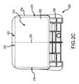
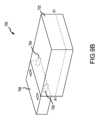
図2A-2Cは、剛体基板204に固定された発泡体圧縮要素202を有する乳房圧縮パドル200の種々の図である。図2A-2Cは、並行して説明される。パドル200は、パドルを撮像システムの圧縮アームに接続するために、概して基板204と一体型であるブラケット部分206を含む。パドル200は、ブラケット部分206と反対側の前縁面208も含み、前縁面208は、圧縮および撮像手技中、患者の胸壁に近接して配置される。例において、基板は、剛体であり得る。本明細書で使用されるように、用語「剛体」は、基板204が乳房の圧縮中に曲がらないのではなく、基板204が基板204の底部に固定された発泡体圧縮要素202より曲がりまたは変形に対して抵抗を示すことを含意する。隆起壁204aが、追加の剛性を提供する。 2A-2C are various views of a
発泡体圧縮要素202は、化学接着剤で、基板204の底部表面に固定され得る。他の例において、圧縮要素の上側表面は、硬質プラスチックまたは他の材料であり得、発泡体圧縮要素202は、それに固定される。複数のボルト、フック、または他の機械的留め具(図示せず)が、この硬質プラスチックをパドル200の剛体基板204に接続するために使用され得る。そのような機械的留め具が使用される場合、乳房を圧縮することが予期される発泡体圧縮材料202のエリアから離れて留め具を配置することによって、圧力点およびそれに関連付けられた結果として生じる不快感を回避し、かつアーチファクトが任意の結果として生じるX線画像内に現れることを防止することが望ましくあり得る。
発泡体圧縮要素202は、いくつかの縁表面を含む。前縁表面210は、圧縮および撮像手技中、患者の胸壁に近接して配置されるように、基板204の前縁面208に近接して配置される。後縁表面212は、ブラケット部分206に近接して、前縁表面210と反対側に配置される。側方縁表面214、216も、描写されている。一般に、これらの側方縁表面214、216は、乳房の内側および外側側面を説明するために典型的に使用される、専門用語と一貫して、内側または外側側方縁表面として描写され得る。当然ながら、当業者は、同じ圧縮パドル200が、乳房のいずれかを一度に1つずつ圧縮するために使用され得、それが、発泡体圧縮材料202の側方縁表面に対して、用語「内側」および「外側」の適用を事実上変化させるであろうことを認識するであろう。さらに、中央平面220が、それらのほぼ中点において側方縁表面214、216間に配置される。中央平面220は、発泡体圧縮材料202の下面上に配置される圧縮表面218に実質的に直交して配置される。圧縮表面218の一部は、圧縮中、乳房に接触するであろう。別の例において、発泡体圧縮材料202は、生体適合性カバーで被覆され得、それは、発泡体圧縮材料202が体液を吸収することから保護し得る。例において、それは、使い捨てまたは清浄可能であり得る。患者経験を改善するために、カバーは、それが患者に接触する場所において、軟質材料から製造され得る。流体が発泡体圧縮材料202の中に浸透することを防止するために、反対のプラスチック側が、発泡体圧縮材料202に接触し得る。境界面222は、圧縮表面218が前縁表面210に出合う場所に位置する。圧縮中、境界面222の形状は、発泡体圧縮材料202を画定することおよびその機能に役立つ。
図2Dは、撮像システムのための圧縮システム250の正面図である。圧縮システム250は、圧縮パドル200の形態における第1の圧縮要素を含み、圧縮パドル200は、剛体基板204と、それに固定される発泡体圧縮要素202とを有する。この場合、乳房支持プラットフォーム252である第2の圧縮要素も、描写される。乳房支持プラットフォーム252の上側表面256上に置かれた乳房254も、描写される。使用中、乳房254は、圧縮パドル200による力Fの適用によって圧縮される。発泡体圧縮材料202は、圧縮が増加するにつれて、変形し、乳房254の輪郭に形状適合する。したがって、力Fが増加させられるにつれて、乳房254および発泡体圧縮材料202の両方の圧縮が、生じる。この圧縮は、乳房254が中央平面220に沿って実質的に中心を置かれると、前縁表面210において中央平面220に近接する発泡体圧縮材料202の圧縮のパーセンテージによって画定され得る。他の例において、境界面222の輪郭が、発泡体圧縮材料202の圧縮を画定し得る。 FIG. 2D is a front view of a
上で説明されるように、発泡体圧縮材料202は、正面縁表面210の非圧縮高さHを有する。例において、非圧縮高さHは、約1インチ~約2インチであり得る。別の例において、非圧縮高さHは、約2インチ~約3インチであり得る。別の例において、非圧縮高さHは、約3インチ超であり得る。試験を通して、約3インチの非圧縮高さHが、小から大のかなりの数の乳房サイズの圧縮のために十分であることが決定されている。トモシンセシス撮像手技に先立って、乳房254は、ある撮像条件まで圧縮され得、その撮像条件は、一例において、乳房を十分に安定させ、乳房を幾分圧縮するという条件である。硬質圧縮パドルを用いた圧縮が乳房のかなりの平坦化をもたらす以前のシステムと異なり、乳房が圧縮されるべき撮像条件は、結果として生じるトモシンセシス画像が管理可能な数である厚さまでであることのみ必要である。そのような管理可能な数は、診断上のかなりの数であり得、結果として生じる乳房画像スライスがスライス間の十分な区別を提供し得るが、臨床医によるかなりより長い精査時間を余儀なくさせるであろうような多数の画像を有しないような数である。 As explained above, the foam compressed
例において、乳房254のこの撮像条件は、正面縁表面210における発泡体圧縮材料202の完全な圧縮に先立って到達される。図2Dは、乳房254が撮像条件下にあるために要求される最大量までの発泡体圧縮材料の圧縮を描写する。例証目的のために、図2Dは、発泡体圧縮材料202の中央平面220上に中心を置かれた乳房254を描写する。したがって、この位置における発泡体圧縮要素202の一部は、完全に圧縮されず、図2Dにおいて、不完全に圧縮された高さH’として描写される。この不完全に圧縮された高さH’は、前縁表面210において測定される発泡体圧縮材料202の部分である一方、発泡体圧縮材料202の最も圧縮された部分は、依然として、さらなる力が乳房254に加えられた場合、さらに圧縮され得る。例において、乳房の撮像条件は、発泡体圧縮材料202の一部のみが完全に圧縮された高さH’に到達するときに到達され得る。 In the example, this imaging condition of
境界面222の形状は、発泡体圧縮材料202の圧縮を画定し得る。圧縮表面と前縁表面との間の境界面が乳房の全長に沿って略平坦に押される、従来技術の薄い発泡体パッドと異なり、技術の発泡体圧縮材料202は、乳房254全体の大部分に沿って湾曲形状を維持する。境界面222は、例えば、乳房254の内側側面に近接する第1の接触点258から乳房254の外側側面に近接する第2の接触点260まで、略平滑曲率256を画定する。しかしながら、従来技術の薄い発泡体パッドは、第1の接触点から第2の接触点までほぼ平坦である。 The shape of the
薄いクッションである従来技術の発泡体パッドと異なり、本明細書に説明される発泡体圧縮材料202は、乳房と支持剛体基板との間の材料のかなりの部分が、乳房が撮像条件に到達することに先立って完全に圧縮される必要がない厚さである。この文脈において使用されるような「完全に圧縮された」とは、その上に乳房が安定にされ、それを用いて撮像される撮像システムを用いた発泡体のさらなる圧縮が可能ではないように、発泡体圧縮材料の一部が圧縮されている条件を想定する。実際、薄い発泡体の完全な圧縮が達成される条件下において、さらなる加力は、発泡体材料が任意の顕著なレベルのクッション性をもはや提供しないほど完全に圧縮されているので、多くの場合、かなりの不快感を患者にもたらす。実際、発泡体が、完全に圧縮されると、圧縮感覚は、発泡体を全く利用しない剛体パドルのそれにより類似する。乳房のサイズおよび密度等の要因に応じて、完全に圧縮する厚い発泡体の部分は、乳房と接触するエリアに実質的に沿って完全に圧縮された条件に到達し得るより薄い発泡体材料と比較して、限定される。本技術の例において、完全な発泡体圧縮は、薄い発泡体用途に一般的である圧縮された乳房のエリア全体に実質的に沿ってとは対照的に、胸壁に近接して、かつ胸壁から所定の距離だけ離れてのみ生じ得る。 Unlike prior art foam pads that are thin cushions, the foam compressed
図3Aは、ある例による、発泡体圧縮材料302の除去可能部分302aを有する圧縮パドル300の上面図である。発泡体圧縮材料302は、上記および本明細書のいずれかの場所に説明されるような特定の利点を有するが、その使用は、発泡体圧縮材料302が透明ではないので、乳房の位置付けを技術者のために幾分困難にし得る。その点に関して、提案される技術は、1つ以上の補助的除去可能部分302aを有する発泡体圧縮材料302を検討する。これらの補助的部分302aは、乳房のかなりの圧縮に先立って、除去され得る(点線354によって描写される)。剛体基板304は、透明プラスチックから製造されるので、乳房354は、さらなる圧縮に先立って、依然として、それを通して視認され、適正に位置付けられ得る。さらに、視認可能な乳房354の一部を有することによって、自動暴露制御(AEC)手技も、実施され得る。AECは、完全に自動であり得、システムは、最適暴露を決定するために、最も高密度の領域に関して、事前パルス暴露に続いて乳房またはその一部を探す。複数のAECマーカが、圧縮パドル300上に描写される。これらのマーカは、自動AECアルゴリズムの代わりに使用されることができ、選択される場合、アルゴリズムに代わり暴露が基づくべき乳房の領域を識別する。いくつかのAECマーカは、発泡体圧縮材料302の除去可能部分302aに近接して存在する。したがって、圧縮に先立って、適切なAECマーカが、適切な線量測定および記録のために、乳房の位置、発泡体の存在、または他の要因に基づいて選択され得る。 FIG. 3A is a top view of a
使用中、技術者は、発泡体圧縮材料302の除去可能部分302aのうちの1つ以上のものを最初に除去し得る。その場合、定位置に留まる発泡体圧縮材料302の一部は、本明細書のいずれかの場所に説明されるように、例えば、接着剤によって、剛体基板304に固定されるであろう。乳房354が、その初期位置に設置されると、概して、その位置を安定させるように、前縁表面310に近接する発泡体圧縮材料302によって、最小限で圧縮され得る。初期圧縮が、実施されると、技術者は、発泡体圧縮材料の除去された部分302aを発泡体圧縮材料302に隣接してそれらの元々の位置に再挿入し得る。これは、手によって、除去された部分302aを操作または圧縮し、それらを適切な位置に収めることによって実施され得る。そのように位置付けられると、圧縮は、上で説明される撮像条件に到達するまで、継続し得る。撮像条件までの圧縮は、補助的部分302aの再挿入を伴わずに取得され得るが、その再挿入は、乳房354にわたって均一な加力を確実にし、結果として生じる画像に有害な影響を及ぼし得る膨隆、組織襞等の潜在性を排除することに役立つ。しかしながら、補助的部分302aに近接する発泡体圧縮材料302の縁は、補助的部分302aが撮像のための定位置にあるときでも、画像アーチファクトを形成し得ることが発見されている。これらのアーチファクトは、撮像後処理中に除去され得る。 During use, a technician may first remove one or more of the
図3Bは、別の例による、発泡体圧縮要素302の複数の除去可能部分を有する圧縮パドル300の上面図である。図3Aに関して上で説明されるように、圧縮パドル300は、補助的部分302aを含み、それらは、乳房354のかなりの圧縮に先立って除去され得、したがって、乳房354は、視認可能なままであり、その位置付けを容易にし得る。乳房354が、その初期位置に設置されると、概して、その位置を安定させるように、前縁表面310に近接する発泡体圧縮材料302によって、最小限で圧縮され得る。初期圧縮が、実施されると、技術者は、この場合、発泡体圧縮材料302によって包囲される発泡体圧縮材料の補助的部分302aをその元々の位置に再挿入し得る。他の除去可能部分は、異なり得るように成形される。例えば、三角形、卵形、または他の形状のカットアウトが、特定の用途のための要求または所望に応じて、圧縮パドル300上の任意の場所で利用され、位置付けられ得る。 FIG. 3B is a top view of a
図4は、別の例による、発泡体圧縮要素402を有する圧縮パドル400の斜視図である。パドル400は、パドル400を撮像システムの圧縮アームに接続するための基板404と概して一体型であるブラケット部分406を含む。パドル400は、ブラケット部分406と反対側の前縁面408を含み、それは、圧縮および撮像手技中、患者の胸壁に近接して配置される。前縁面408に近接する基板404の突出部分484は、乳房(図示せず)に向かって下向きに延びている。本明細書のいずれかの場所に説明されるような発泡体圧縮材料402は、突出部分484の底部(随意に、側面)に固定される。隆起壁404aは、追加の剛性を提供する。 FIG. 4 is a perspective view of a
図4に描写されるパドル400は、MLO視マンモグラムおよびMLO位置におけるトモシンセシス手技において特に有用である。そのような位置において、腋窩が可視化されることが可能であることが望ましく、したがって、生物学的に有意義な量の発泡体402が、胸壁から延びなければならない。利用される発泡体の実際の厚さは、乳房のサイズに基づいて変動させられ得る。例えば、約2インチの発泡体402が、最大乳房のために望ましいであろうことが決定されている。より小さい乳房は、そのような厚さの発泡体402を要求しないこともある。発泡体402を生物学的に有意義なエリアのみに制限することは、その下に配置される発泡体を有していない基板404の部分を通して乳房の残部を可視化することが可能となる技術者による乳房の可視性を最大化する。加えて、図4に描写されるように、突出部分484および発泡体402を位置付けることは、乳房壁および胸筋筋肉の安定化を可能にする。したがって、乳房は、容易に安定にされ、不快感が、低減させられる。 The
さらに、パドルの一部のみ(例えば、発泡体402)が、乳房に触れるように意図される。発泡体材料402を突出部分484の下方に配置することによって、小容積486が、形成される。したがって、乳房の自然な弾性変形が、技術者のための乳房へのアクセスの容易性を最大化しながら、皮膚襞が現れる機会を最小化するであろう。間隙486は、一例において、アクセスの容易性のために、約19mmの高さ(例えば、平均的手の厚さに類似する)であり得る。別の例において、間隙486は、約5mmの高さであり、最大乳房厚変動の最大量を1cmを下回るように制限し得る。さらに、構成は、潜在的垂れ下がりを限定または防止する。さらに、トモシンセシス中に使用されるとき、改善された可視化のための別個の組織への完全な圧縮の必要性が、低減させられ、したがって、図4に描写される構成をより高い快適性のために実行可能なものにする。標準的マンモグラム撮像において、乳房の厚さにおける最大変動性も、描写されるパドル400を用いて最小化される。 Additionally, only a portion of the paddle (eg, foam 402) is intended to touch the breast. By placing
図5は、多材料乳房圧縮パドル500の分解斜視図を描写する。このパドル500は、硬質プラスチック部分または本体502と、1つ以上の厚い発泡体外形504と、硬質プラスチック本体502および発泡体外形504を実質的に包囲する薄い可撓性材料506bとを含む。発泡体外形504は、例えば、それらがパドル500の側壁512に近接して概して位置するので、乳房の可視性を改善するように位置付けられる。剛体本体502の詳細は、下で説明される。薄い材料506に関して、それは、圧縮パドル500を実質的に包囲し得るシースまたはバッグの形態において製造され得る。この構成において、基部502と、発泡体外形504とを含む圧縮パドル500全体は、薄い材料506によって被覆される。これは、汗または血液等の体液(生検手技中に生成され得る)による本体502および発泡体外形504の汚染を防止することに役立つ。描写される薄い材料506は、上で説明されるように、収縮包装材料であり得る。収縮包装材料506への熱の印加後(パドル500を覆って配置されると)、収縮包装材料506は、恒久的損傷または変形(例えば、切断、スライス、または引き裂き)を伴わずに圧縮パドル500から除去することが困難である。発泡体外形504は、収縮包装材料506によって加えられる対応する力を上回る変形に対する抵抗を提供することが、望ましくあり得る。これは、乳房圧縮に起因した発泡体外形504のさらなる変形に先立つ薄い材料506の収縮に起因した発泡体外形504のかなりの変形を防止することに役立つであろう。 FIG. 5 depicts an exploded perspective view of a multi-material
薄い材料506が収縮包装材料または他の類似緊密適合材料である例において、薄い材料506は、乳房撮像手技を行うことに先立って、圧縮要素500に適用され得る。熱が、次いで、圧縮要素500および薄い材料506に印加され、薄い材料506に収縮させ、発泡体外形504に及ぶ可撓性材料506の部分の張力を増加させる(但し、外形504を実質的に圧縮するような張力を加えずに)。いくつかの例において、加熱プロセスは、乳房圧縮要素500を加温し、乳房が圧縮されるにつれて、患者快適性を増加させるために、乳房撮像手技の直前に一度生じ得る。加えて、薄い材料506は、有利なこととして、使い捨てである。したがって、第1の患者での使用後、薄い材料506は、除去され得、新しい薄い材料506が、後続患者のために適用され得る。これは、患者間で乳房圧縮要素500の表面を清浄または別様に処理する必要性を排除し得る。 In examples where
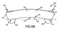
図6A-6Cは、それぞれ、図5の乳房圧縮パドル500の例の部分的斜視、正面、および側面図を描写する。薄い材料は、明確にするために描写されない。薄い材料を定位置に伴う圧縮パドル500の性能は、図7Aおよび7Bに関して下で説明される。上で説明されるように、圧縮パドル500は、本体502と、発泡体外形504とを含む。本体502は、単一の硬質プラスチック片から概して形成される。圧縮パドル500の底部壁または基部508は、略凹面表面510を含み、それは、概して、形状において乳房および/または圧縮された乳房に対応し得る。略凹面表面510は、概して、圧縮パドル500の側壁512間に延びている。略凹面表面510は、乳房に加えられる力をより等しく分散させ、乳房の形状により密接に対応することに役立つ。そのような構成は、乳房が圧縮されるとき、より快適性を患者に提供することに役立ち得る。加えて、略凹面表面510は、下でさらに詳細に説明されるように、乳房の圧縮中、その中で薄い材料が変形し得る容積を提供する。略凹面表面510は、基準平面Pを画定する2つの外側縁部分514を含む。中心部分516は、中心部分516が、基準平面Pに対して持ち上げられ、またはその上方に配置されるように、外側縁部分514と非同一平面上にある。中心部分516は、水平(例えば、基準平面Pまたはパドル500の軸Aと平行)であり得るか、または、パドル500の正面壁518から背面壁520まで下向きに傾けられ得る。これは、パドル500を乳房の形状にさらに形状適合させることに役立ち得る。 6A-6C depict partial perspective, front, and side views, respectively, of the example
パドル500の隣接する壁(例えば、側壁512、正面壁518、および背面壁520)は、各壁の上側縁から基部508に近接する場所まで延びている間隙またはスロット522によって互いに分離され得る。これらの間隙またはスロット522は、種々の壁(例えば、下で説明される理由から、側壁512)のより大きい撓みを可能にする。正面壁518の撓みも、圧縮手技中、その特徴が胸壁に接触するので、患者快適性を改善し得る。側壁512の各々は、それから上向きに延びている構造または壁延長部524を含み得、それは、乳房圧縮中、薄い可撓性材料への張力を維持するように、薄い可撓性材料のための張力要素としての機能を果たす。構造524は、側壁512と一体型であるか、または、それとは別であり得る。構造524の形状は、用途に応じて変動し得るが、図に描写される巻き上げられた構造は、薄い材料への損傷を防止するために有利であり得る。さらに、構造524は、圧縮パドル500の最も高い構成要素(この場合、正面壁518)の高さまたはそのすぐ上の高さまで延び得る。これは、構造524が、構造524が撓んだ場合でも、薄い材料への張力を維持することを可能にする。 Adjacent walls of paddle 500 (eg,
薄い材料は、体液による汚染を防止するように、カバーを1つ以上の発泡体外形504に提供するためにも使用され、したがって、発泡体外形504は、一部の患者で再利用され得る。2つの発泡体外形504が、概してパドル500の側壁512の近傍の圧縮パドル500の基部508に固定される実質的に半円筒形の要素として、図5に描写される。発泡体外形504を側壁512(略凹面表面510の最低部分)の近傍に位置決めすることによって、パドル500の持ち上げられた中心部分516は、発泡体外形504の最上部分の上方に留まる。発泡体外形504は、接着剤で基部508に固定され得る。発泡体外形504は、下で説明される性能を可能にするように、薄い材料と圧縮パドル500の基部508との間の分離を増加させる。発泡体外形504の湾曲底部表面は、その張力を維持するように、薄い材料がその周囲にスムースに巻かれることを可能にする。 The thin material is also used to provide a cover to the one or
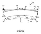
図7Aおよび7Bは、それぞれ、第1および第2の条件における図5の乳房圧縮パドル500の正面図を描写する。図7Aの第1の条件は、乳房圧縮パドル500が中立条件にあるとき(例えば、パドル500が乳房を圧縮していないとき)である。この条件において、薄い材料506は、パドル500の周囲で比較的に緊張して留まる。パドル500構成に応じて、薄い材料506は、ここでのように、側壁512の一部に接触し得る。さらに、薄い材料506は、薄い材料506がバッグ形状の構成にある場合、正面壁518と接触し得る。さらに、薄い材料506は、発泡体外形504を包み込み、力がそれに加えられると、この中立位置であっても、若干、それらの外形504を圧縮し得る。薄い材料506への張力は、概して、各側壁512上の構造524によって維持される。 7A and 7B depict front views of the
図7Bの第2の条件において、力Fが、薄い材料506の下面506bに加えられる。これは、パドル500が乳房に押し付けられるときに生じ、例えば、撮像手技のために、乳房を圧縮または別様に安定させ得る。加えられる力Fが、下面506aを上向きに撓ませるにつれて、発泡体外形504は、撓むDように構成される。撓みDの量は、少なくとも部分的に発泡体外形504材料の密度、加えられる力Fの量、薄い材料506の弾性、張力構造524の弾力性、および他の要因に基づき得る。さらに、力Fが増加するにつれて、張力構造524は、薄い材料506の上部側506aへの張力Tが増加するように、曲線Cまたは他の方向に下向きに撓み得る。これは、材料が力Fに起因して崩れないように、薄い材料506への張力を維持することに役立つ。したがって、圧縮パドル500が、乳房を圧縮するために使用されるとき、発泡体外形504および薄い材料506は、圧縮が開始するにつれて、乳房を安定させるように作用する。しかしながら、圧縮は、発泡体外形504が完全に変形し、力が、基部508を介して、乳房に直接加えられる(薄い材料506がそれらの間に位置する)まで、継続し得る。発泡体外形504の構成は、図7Aおよび7Bに描写されるように、特に、MLO位置において実施される圧縮のために有利である。発泡体外形504は、特に、それらが2つの外形504の上側が腋下に近接する腋窩組織に接触するように配置されるので、増加させられた快適性を患者に提供する。したがって、その場所の圧縮は、発泡体外形504によって衝撃緩和される。 In the second condition of FIG. 7B, a force F is applied to the
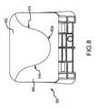
図8は、別の例による、発泡体圧縮要素602を有する圧縮パドル600の上面図である。発泡体圧縮材料602は、本明細書のいずれかの場所に説明されるように、剛体基板604に固定される。この例において、発泡体圧縮材料602は、乳房の形状を模倣する湾曲外側輪郭602aを含む。この湾曲外側輪郭602aは、その全長に沿って一貫した曲線である必要がない。それにもかかわらず、この湾曲外側輪郭602aは、外側および内側側方縁表面614、616を画定し得る。そのような湾曲外側輪郭602aに関連付けられた少なくとも1つの利点は、位置付けのための乳房の増加させられた可視性を含む。加えて、乳房撮像システムは、患者に視覚的に威圧的であり得る(かつ不快感に関連付けられる)ので、湾曲外側輪郭602aは、より心地よい経験の印象を与え得る。 FIG. 8 is a top view of a
図9Aは、別の例による、発泡体圧縮要素702を有する圧縮パドル700の斜視図である。上記のパドルと同様、パドル700は、パドル700を撮像システムの圧縮アームに接続するために、概して基板704と一体型であるブラケット部分706を含む。パドル700は、ブラケット部分706と反対側の前縁面708も含み、それは、圧縮および撮像手技中、患者の胸壁に近接して配置される。隆起壁704aは、追加の剛性を提供する。発泡体圧縮要素702は、基板704の底部表面と実質的に平行であり、圧縮中、乳房に接触するように構成される(但し、生体適合性カバーが、上で説明されるように、発泡体圧縮要素702と乳房との間に配置され得る)圧縮表面788を含む。 FIG. 9A is a perspective view of a
図9Aにおける圧縮要素702は、各々が異なる密度を有する複数の発泡体片を利用する。2つの発泡体片の構成および向きは、発泡体圧縮要素702の異なる領域が、圧縮に異なって抵抗することを可能にし、それは、より高い快適性、より均一な圧縮、および他の利点につながる。いくつかの異なる構成が、種々の破線とともに、図9Aに描写される。一般に、第1の密度を有する第1の発泡体は、線の片側に描写される一方、第2の密度を有する第2の発泡体は、線の他側に描写される。種々の線は、隣接する発泡体片間の別々の接触部を表し、接触部において、典型的に、接着剤が、発泡体片を一緒に固定するために位置し得る。別の例において、発泡体の第1の部分が、形成され、次いで、金型内に設置され得、そこで、発泡体の第2の部分が、その上に形成され得、したがって、接着剤の必要性を排除する。典型的に、1つのみの接触部が、圧縮要素702内で利用される(例えば、2つの異なる密度の2つの別々の発泡体部分を接合する)。しかしながら、他の例において、複数の接触部が、3つ以上の別々の発泡体部分を互いに接合するために利用され得る。そのような場合において、隣接する発泡体部分は、異なる密度を有し得るが、隣接しない発泡体部分は、同じ密度を有し得る。他の例において、発泡体圧縮要素702は、全体を通して変動する密度を有する単一構造片であり得る。
接触部A1は、前縁表面790および圧縮表面788に対して垂直でない角度で配置され、それらの2つの表面788、790間の接合部と交差する。圧縮表面788に対する接触部A1の角度は、特定の用途のための要求または所望に応じて、変動し得る。この例において、接触部A1の場所は、圧縮表面788を形成するために、単一の発泡体部分のうちの1つ(ここにおいて、接触部A1の左の部分)しかもたらさない。接触部A2は、前縁表面790および圧縮表面788と非垂直に配置されるが、直接、圧縮表面788のみと交差する。したがって、接触部A2の両側に配置される両発泡体部分が、圧縮表面788を形成する。接触部A1またはA2と一貫して構成される圧縮要素702を有するパドル700は、各それぞれの接触部の右に配置されるより高い密度の発泡体部分を含み得る。これらのより高い密度発泡体は、接触部の左に配置されるより低い密度発泡体ほど圧縮せず、それは、撮像のために乳房組織を胸壁から離れるように引く一方、患者のための不快感を低減させることに役立ち得る。 Contact A1 is disposed at a non-perpendicular angle to leading
接触部A3は、前縁表面790および圧縮表面788の両方に対して垂直または実質的に垂直な角度に配置されるが、前縁表面790のみと交差する。この例において、接触部A3の場所は、圧縮表面788を形成するために、単一の発泡体部分のうちの1つのみ(ここにおいて、接触部A3の左下の部分)をもたらす。より高い密度の発泡体が、接触部A3の右上の圧縮要素702の部分において使用される場合、圧縮要素702のこの構成は、乳房組織を胸壁から離れるように引くことに役立ち得る。 Contact portion A3 is disposed at an angle perpendicular or substantially perpendicular to both leading
接触部A4は、前縁表面790と実質的に垂直かつ圧縮表面788と実質的に平行に配置される。したがって、接触部A4の下方の発泡体部分のみが、圧縮表面788を形成する。より低い密度の発泡体が、接触部A4の下方に配置される場合、圧縮要素702のその部分は、より低い圧縮力で乳房のためのより高いクッション性を提供するであろう。圧縮力が増加するにつれて、より高い圧縮が、接触部A4の上方の発泡体部分の場所に起因して生じるであろう。 Contact portion A4 is disposed substantially perpendicular to leading
図9Aに描写され、上で説明される接触部A1-A4は、例証目的のためのものにすぎない。他の構成の接触部を有する圧縮要素702も、想定される。そのような他の構成は、3つ以上の発泡体部分が単一圧縮要素内で利用され得るように、複数の接触部を含み得る。さらに、非平面接触部が、要求または所望に応じて、利用され得る。波状、湾曲、および凹面または凸面接触部が、検討される。本明細書に説明される接触部は、本質的に、圧縮要素702を複数の別々の圧縮力の量に分離し、したがって、各圧縮要素702の機能性を大幅にカスタマイズし、撮像、快適性、またはさらなる圧縮を改善するために有利な方法において、乳房を圧縮する。他の利点も、当業者に明白であろう。 The contacts A1-A4 depicted in FIG. 9A and described above are for illustrative purposes only.
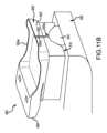
図9Bは、別の例による、発泡体圧縮要素702を有する圧縮パドル700の斜視図である。上記のパドルと同様、パドル700は、ブラケット部分706を含む。発泡体圧縮要素702は、ブラケット706に直接固定され得るか、または、基礎になる構造または骨組704の周囲に形成または別様に固定され得、構造は、上で説明されるように、完全な基板である必要はなく、ある程度の構造剛性を提供し得る。この例において、単一接触部A1が、異なる密度を有する2つの発泡体間に描写される(例えば、より高い密度の発泡体が、接触部A1の上方にあり、より低い密度の発泡体が、下方にある)。上で説明されるような接触部の他の向きも、想定される。 FIG. 9B is a perspective view of a
図10は、その支持プラットフォーム804上に配置される厚い発泡体圧縮要素802を含む撮像システム800の部分的斜視図である。乳房Bが、発泡体圧縮要素802と圧縮パドル806との間で圧縮される。発泡体圧縮要素802を乳房Bの下方に配置することによって、いくつかの利点(改善された快適性の一般的側面に加え)が、達成される。例えば、快適性は、発泡体圧縮要素802が典型的に低温の支持プラットフォーム804からの断熱効果を提供するので、さらに改善される。乳房Bと発泡体圧縮要素802との間の摩擦は、特に、MLO撮像位置において、乳房Bの設置に役立つ。乳房Bは、発泡体圧縮要素が乳房の上方に位置付けられる構成と異なり、技術者により視認可能なままである。さらに、約2インチ厚を有する発泡体圧縮要素を乳房の下方に配置することは、自動暴露制御を介して測定されるとき、乳房の厚さにおいてわずか4%の線量増加をもたらす。 FIG. 10 is a partial perspective view of an
図11Aおよび11Bは、それぞれ、第1の位置および第2の位置における発泡体圧縮要素902および圧縮検出器990を有する圧縮パドル900の正面図である。本明細書のいずれかの場所に説明されるように、圧縮パドル900は、隆起壁904aを有する剛体基板904と、ブラケット906とを含む。乳房支持プラットフォーム992も、描写される。圧縮検出器990が、前縁表面910に近接して配置され、それは、大部分の圧縮が典型的に生じる前縁表面910に近接する発泡体圧縮材料902の圧縮の量を決定するために使用される。例において、圧縮検出器990は、光ファイバピン等の堅い放射線透過性材料であり、それは、剛体基板904の前縁面908に固定され得る。圧縮検出器990は、それに対してピン990がスライドし得るブラケット(図示せず)を用いて固定され得る。別の例において、圧縮検出器990は、発泡体圧縮材料902内に埋め込まれ得る。構成にかかわらず、ピン990の底部990aは、圧縮表面918と概して同じ面上にある。したがって、乳房954が、発泡体圧縮材料902と乳房プラットフォーム992との間で圧縮されるにつれて、発泡体圧縮材料902は、圧縮し、ピン990は、概して発泡体圧縮材料902の圧縮の量に対応する距離だけ、上向きに移動する。ピン990上の段階的マーク990bは、技術者によって手動で、またはパドル900および/または撮像システムに関連付けられた光学または他の読み取り機(図示せず)によって自動的に、読み取られ得る。段階的マークを読み取ることによって、発泡体圧縮材料902の圧縮の総量が、加えられる力、乳房954の計算される高さ等に関して、決定および分析され得る。これは、特に、AEC暴露技法のために有用であり得る。発泡体圧縮材料902の厚さを表す段階的マーク990bは、乳房954の厚さに近いように、オフセットとして使用され得る。段階的マーク990bは、センサによって自動的に読み取られるか、または、技術者によって可視化され、関連付けられたAECプログラムの中に打ち込まれ得る。厚さは、乳房954の厚さを決定するように、支持プラットフォーム992の上方の圧縮パドル900の距離に対応する測定値から自動的に減算され得る。この厚さは、次いで、適切なAEC暴露制御技法を決定するために使用され得る。 11A and 11B are front views of a
図12は、撮像システムにおいて乳房を圧縮する方法1000を描写する。方法1000は、第1の圧縮要素を提供する動作1002から開始する。第1の圧縮要素は、本明細書に説明されるように、剛体基板と、剛体基板に固定された発泡体とを含む圧縮パドルであり得る。発泡体は、内側側方縁表面と、外側側方縁表面と、内側側方縁表面と外側側方縁表面との間に配置された中央平面と、前縁表面と、圧縮表面と、前縁表面と圧縮表面を接続する接合部とを含み得る。随意の動作1004は、発泡体の1つ以上の除去可能部分を除去することを含む。発泡体の除去可能部分を有する圧縮要素が、本明細書に説明される。この動作は、乳房を第2の圧縮要素上に配置することを含む動作1006に先立って、またはその後に実施され得る。第2の圧縮要素は、圧縮表面に面して配置される乳房支持プラットフォームであり得る。乳房の設置中、患者の胸壁は、前縁表面と実質的に整列させられ、乳房の内側側面は、内側側方縁表面に近接して配置され、乳房の外側側面は、外側側方縁表面に近接して配置される。随意の動作1004が、実施された場合、乳房を圧縮することに先立って、発泡体の除去可能部分を挿入する動作1008も、実施され得る。 FIG. 12 depicts a method 1000 of compressing a breast in an imaging system. Method 1000 begins with act 1002 of providing a first compression element. The first compression element can be a compression paddle including a rigid substrate and a foam secured to the rigid substrate, as described herein. The foam has an inner lateral edge surface, an outer lateral edge surface, a central plane disposed between the inner lateral edge surface and the outer lateral edge surface, a leading edge surface, a compression surface, and a leading edge surface. A joint connecting the edge surface and the compression surface may be included. Optional act 1004 includes removing one or more removable portions of the foam. Compression elements having removable portions of foam are described herein. This operation may be performed prior to or after operation 1006, which includes placing the breast on the second compression element. The second compression element may be a breast support platform placed facing the compression surface. During breast placement, the patient's chest wall is substantially aligned with the anterior border surface, the medial aspect of the breast is placed proximate to the medial lateral border surface, and the lateral aspect of the breast is placed in close proximity to the medial lateral border surface. located close to. If optional act 1004 is performed, act 1008 of inserting a removable portion of foam prior to compressing the breast may also be performed.
動作1010において、第1の圧縮要素と第2の圧縮要素との間で乳房を圧縮することが、実施される。乳房は、撮像条件まで圧縮され、撮像条件下において、中央平面と整列させられた前縁表面の一部は、不完全に圧縮された条件まで圧縮される。撮像条件下にあるとき、境界面は、中央平面の外側側面に隣接する第1の曲線と、中央平面の内側側面に隣接する第2の曲線とを画定し得る一方、境界面の直線部分は、第2の圧縮要素と実質的に平行である。トモシンセシス撮像手技等の撮像手技が、動作1012において実施される。それに続いて、随意の動作1014が、実施され得、それは、除去可能部分によって形成されるアーチファクトの可視性を調節するように、撮像手技からの出力を処理することを含む。処理は、トモシンセシススライス画像の組を取得するために、当技術分野において公知のような画像の処理を含み得る。処理はまた、画像内に現れるアーチファクトを除去することを含み得る。 In operation 1010, compressing the breast between a first compression element and a second compression element is performed. The breast is compressed to an imaging condition, and under the imaging conditions, a portion of the leading surface aligned with the midplane is compressed to a partially compressed condition. When under imaging conditions, the interface may define a first curved line adjacent to the outer side of the midplane and a second curved line adjacent to the inner side of the midplane, while the straight portion of the interface , substantially parallel to the second compression element. An imaging procedure, such as a tomosynthesis imaging procedure, is performed at operation 1012. Subsequently, an optional act 1014 may be performed, which includes processing the output from the imaging procedure to adjust the visibility of artifacts formed by the removable portion. Processing may include processing the images as known in the art to obtain a set of tomosynthesis slice images. Processing may also include removing artifacts that appear within the image.
上記の図11Aおよび11Bは、発泡体の厚さ、したがって、乳房の厚さを決定するために、圧縮検出器590の使用を説明する。他の例において、自動暴露制御(AEC)ソフトウェアが、本明細書に説明される発泡体圧縮システムとともに、圧縮検出器590を要求せずに、乳房の厚さを決定するために利用され得る。AECシステムの一部は、発泡体の厚さに起因して、支持プラットフォームの上方の圧縮パドル高さと異なるであろう圧縮された乳房の厚さを識別する。乳房形状を識別および補正し、マンモグラム状画像を提供する画像処理ソフトウェアも、発泡体圧縮要素を採用する撮像システムにおいて利用され得る。発泡体によって圧縮された乳房の形状は、剛体平坦パドルを使用して圧縮された乳房の平坦形状と異なるであろうから、この画像補正は、有益であることが証明され得る。乳房の厚さは、入手されたトモシンセシス画像からも決定され得る。この情報は、乳房密度等の画像から取得される情報とともに、記憶され得、配信される乳房線量を計算するために使用され得る。AECは、要求される線量を検出器に配信するように、暴露を制御するために利用される。この暴露に続いて、AECは、乳房の厚さとkVおよびmAs等の暴露情報とに基づいて、実際の配信される乳房線量を計算する。この情報は、後のアクセスおよび使用のために保存され得る。 11A and 11B above illustrate the use of a compression detector 590 to determine the thickness of the foam and, therefore, the thickness of the breast. In other examples, automatic exposure control (AEC) software may be utilized with the foam compression system described herein to determine breast thickness without requiring a compression detector 590. Some AEC systems identify the thickness of the compressed breast, which will be different from the compression paddle height above the support platform due to the thickness of the foam. Image processing software that identifies and corrects breast shape and provides mammogram-like images may also be utilized in imaging systems employing foam compression elements. This image correction may prove beneficial since the shape of a breast compressed by foam will be different from the flat shape of a breast compressed using a rigid flat paddle. Breast thickness can also be determined from the obtained tomosynthesis images. This information, along with information obtained from the images such as breast density, may be stored and used to calculate the delivered breast dose. AEC is utilized to control exposure to deliver the required dose to the detector. Following this exposure, the AEC calculates the actual delivered breast dose based on breast thickness and exposure information such as kV and mAs. This information may be saved for later access and use.
図13は、圧縮された乳房の厚さを計算する1つの方法1100を描写する。方法は、少なくとも部分的に乳房を支持プラットフォームと圧縮パドルとの間で圧縮する動作1102から開始する。圧縮パドルは、本明細書に描写される例等の乳房と接触する圧縮発泡体材料を含み得る。動作1104において、圧縮パドルと支持プラットフォームとの間の分離距離が、決定される。例において、分離は、線形または他のエンコーダ、近接度センサ、または他の位置センサを使用することによって、乳房撮像デバイスの圧縮システムに関連付けられたエンコーダを利用して決定され得る。動作1106において、圧縮パドルからの乳房のオフセット距離が、決定される。このオフセット距離は、圧縮発泡体材料の圧縮された厚さに対応する。例において、オフセットを決定することは、図11Aおよび11Bに関連して説明される圧縮検出器等の圧縮検出器を自動的に読み取る動作1108を含む。動作1110において、少なくとも部分的に分離距離とオフセット距離とに基づいて、乳房の厚さが、決定される。この情報は、乳房のさらなる撮像を実施するために利用され得る(例えば、少なくとも部分的に乳房の厚さに基づいてX線暴露技法を計算するために、動作1112)。マンモグラフィ画像品質および患者放射線量は、アノード材料、X線エネルギー(kVp)、およびX線フィルタ材料の選択肢等のX線暴露技法に依存する。正確または合理的に計算または推定された乳房の厚さは、適切なX線暴露技法が圧縮下の乳房のために使用されることを確実にすることに役立つ。 FIG. 13 depicts one method 1100 of calculating compressed breast thickness. The method begins with an operation 1102 of at least partially compressing the breast between a support platform and a compression paddle. The compression paddle may include a compressed foam material in contact with the breast, such as the examples depicted herein. At operation 1104, a separation distance between the compression paddle and the support platform is determined. In examples, separation may be determined utilizing an encoder associated with the compression system of the breast imaging device, by using a linear or other encoder, proximity sensor, or other position sensor. In operation 1106, the offset distance of the breast from the compression paddle is determined. This offset distance corresponds to the compressed thickness of the compressed foam material. In the example, determining the offset includes an act 1108 of automatically reading a compression detector, such as the compression detector described in connection with FIGS. 11A and 11B. In operation 1110, a breast thickness is determined based at least in part on the separation distance and the offset distance. This information may be utilized to perform further imaging of the breast (eg, operation 1112 to calculate an x-ray exposure technique based at least in part on breast thickness). Mammography image quality and patient radiation dose depend on the x-ray exposure technique, such as the anode material, x-ray energy (kVp), and x-ray filter material selection. Accurate or reasonably calculated or estimated breast thickness helps ensure that appropriate X-ray exposure techniques are used for breasts under compression.
図14は、圧縮された乳房のための放射線量を決定する方法1200を描写する。方法は、少なくとも部分的に乳房を支持プラットフォームと圧縮パドルとの間で圧縮する動作1202から開始する。圧縮パドルは、本明細書に描写される例等の乳房と接触する圧縮発泡体材料を含み得る。動作1204は、圧縮された乳房のトモシンセシス画像の組を入手することを含む。これらのトモシンセシス画像から、乳房のいくつかの特性が、決定され得る。例えば、動作1206は、少なくとも部分的にトモシンセシス画像に基づいて、圧縮された乳房の厚さを決定することを想定する。動作1208は、少なくとも部分的にトモシンセシス画像に基づいて、圧縮された乳房の密度を決定することを想定する。この情報から、X線撮像のための乳房線量が、少なくとも部分的に決定された厚さと密度とに基づいて、計算され得る。発泡体材料を伴う圧縮パドル下で実際の乳房の厚さを機械的に測定するときに存在する不確実性に起因して、この撮像ベースの方法は、より正確な乳房の厚さおよび密度データを提供し、試験から乳房放射線量のより正確な推定をもたらし得る。 FIG. 14 depicts a method 1200 of determining radiation dose for a compressed breast. The method begins with an operation 1202 of at least partially compressing the breast between a support platform and a compression paddle. The compression paddle may include a compressed foam material in contact with the breast, such as the examples depicted herein. Act 1204 includes obtaining a set of compressed breast tomosynthesis images. From these tomosynthesis images, several characteristics of the breast can be determined. For example, assume that operation 1206 determines the thickness of the compressed breast based at least in part on the tomosynthesis image. Act 1208 contemplates determining the density of the compressed breast based at least in part on the tomosynthesis image. From this information, a breast dose for X-ray imaging can be calculated based at least in part on the determined thickness and density. Due to the uncertainties that exist when mechanically measuring actual breast thickness under compression paddles involving foam materials, this imaging-based method provides more accurate breast thickness and density data. and may result in more accurate estimates of breast radiation dose from the test.
図15は、本例のうちの1つ以上のものが実装され得る好適な動作環境1300の一例を図示する。この動作環境は、本明細書に開示される撮像システムの中に直接組み込まれ得るか、または、本明細書に説明される撮像および圧縮システムから別であるが、それらを制御するために使用されるコンピュータシステムの中に組み込まれ得る。これは、好適な動作環境の一例にすぎず、使用または機能性の範囲に関する任意の限定を示唆することを意図するものではない。使用のために好適であり得る他の周知のコンピューティングシステム、環境、および/または構成は、限定ではないが、撮像システム、パーソナルコンピュータ、サーバコンピュータ、ハンドヘルドまたはラップトップデバイス、マルチプロセッサシステム、マイクロプロセッサベースのシステム、プログラマブル消費者電子機器、例えば、スマートフォン、ネットワークPC、ミニコンピュータ、メインフレームコンピュータ、タブレット、上記のシステムまたはデバイスのいずれかを含む分散型コンピューティング環境等を含む。 FIG. 15 illustrates an example of a suitable operating environment 1300 in which one or more of the examples may be implemented. This operating environment may be integrated directly into the imaging systems disclosed herein or may be separate from, but used to control, the imaging and compression systems described herein. can be incorporated into a computer system. This is only one example of a suitable operating environment and is not intended to suggest any limitation as to scope of use or functionality. Other well-known computing systems, environments, and/or configurations that may be suitable for use include, but are not limited to, imaging systems, personal computers, server computers, handheld or laptop devices, multiprocessor systems, microprocessors, etc. based systems, programmable consumer electronics such as smart phones, network PCs, minicomputers, mainframe computers, tablets, distributed computing environments including any of the systems or devices described above, and the like.
その最も基礎的な構成において、動作環境1300は、少なくとも1つの処理ユニット1302と、メモリ1304とを典型的に含む。コンピューティングデバイスの正確な構成およびタイプに応じて、メモリ1304(とりわけ、乳房の厚さを計算、X線放射線量を決定、または本明細書に開示される他の方法を実施するための命令を記憶する)は、揮発性(RAM等)、不揮発性(ROM、フラッシュメモリ等)、または2つのある組み合わせであることができる。この最も基礎的な構成は、破線1306によって、図11に図示される。さらに、環境1300は、限定ではないが、磁気または光ディスクまたはテープを含む記憶デバイス(リムーバブル1308および/または非リムーバブル1310)も含むことができる。同様に、環境1300は、タッチスクリーン、キーボード、マウス、ペン、音声入力等の入力デバイス1314、および/またはディスプレイ、スピーカ、プリンタ等の出力デバイス1316も有することができる。LAN、WAN、ポイントツーポイント、Bluetooth(登録商標)、RF等の1つ以上の通信接続1312も、環境内に含まれることができる。 In its most basic configuration, operating environment 1300 typically includes at least one processing unit 1302 and memory 1304. Depending on the exact configuration and type of computing device, memory 1304 may contain, among other things, instructions for calculating breast thickness, determining x-ray radiation dose, or performing other methods disclosed herein. storage) can be volatile (such as RAM), non-volatile (such as ROM, flash memory, etc.), or some combination of the two. This most basic configuration is illustrated in FIG. 11 by dashed line 1306. Additionally, environment 1300 may also include storage devices (removable 1308 and/or non-removable 1310) including, but not limited to, magnetic or optical disks or tape. Similarly, environment 1300 may also have input devices 1314, such as a touch screen, keyboard, mouse, pen, voice input, and/or output devices 1316, such as a display, speakers, printer, etc. One or more communication connections 1312, such as LAN, WAN, point-to-point, Bluetooth, RF, etc., may also be included in the environment.
動作環境1300は、少なくともある形態のコンピュータ読み取り可能な媒体を典型的に含む。コンピュータ読み取り可能な媒体は、処理ユニット1302または動作環境を有する他のデバイスによってアクセスされ得る任意の利用可能な媒体であることができる。一例として、限定ではなく、コンピュータ読み取り可能な媒体は、コンピュータ記憶媒体および通信媒体を含むことができる。コンピュータ記憶媒体は、コンピュータ読み取り可能な命令、データ構造、プログラムモジュール、または他のデータ等の情報の記憶のための任意の方法または技術内に実装される揮発性および不揮発性のリムーバブルおよび非リムーバブル媒体を含む。コンピュータ記憶媒体は、RAM、ROM、EEPROM、フラッシュメモリまたは他のメモリ技術、CD-ROM、デジタル多用途ディスク(DVD)または他の光学記憶装置、磁気カセット、磁気テープ、磁気ディスク記憶装置または他の磁気記憶デバイス、ソリッドステート記憶装置、または所望の情報を記憶するために使用され得る任意の他の有形媒体を含む。通信媒体は、搬送波または他の移送機構等の変調されたデータ信号において、コンピュータ読み取り可能な命令、データ構造、プログラムモジュール、または他のデータを具現化し、任意の情報配信媒体を含む。用語「変調されたデータ信号」は、その特性組のうちの1つ以上のものを有する信号、または情報を信号においてエンコードするような様式で変化した信号を意味する。一例として、限定ではなく、通信媒体は、有線ネットワークまたは直接有線接続等の有線媒体、および音響、RF、赤外線等の無線媒体、および他の無線媒体を含む。上記のいずれかの組み合わせも、コンピュータ読み取り可能な媒体の範囲内に含まれるべきである。コンピュータ読み取り可能なデバイスは、コンピュータ記憶媒体を組み込むハードウェアデバイスである。 Operating environment 1300 typically includes at least some form of computer readable media. Computer readable media can be any available media that can be accessed by processing unit 1302 or other device having an operating environment. By way of example and not limitation, computer-readable media can include computer storage media and communication media. Computer storage media includes volatile and nonvolatile, removable and non-removable media implemented in any method or technology for storage of information such as computer-readable instructions, data structures, program modules, or other data. including. Computer storage media may include RAM, ROM, EEPROM, flash memory or other memory technology, CD-ROM, digital versatile disk (DVD) or other optical storage, magnetic cassette, magnetic tape, magnetic disk storage or other Includes magnetic storage devices, solid state storage, or any other tangible medium that can be used to store desired information. Communication media embodies computer-readable instructions, data structures, program modules, or other data in a modulated data signal such as a carrier wave or other transport mechanism and includes any information delivery media. The term "modulated data signal" means a signal that has one or more of its characteristics set or changed in such a manner as to encode information in the signal. By way of example, and not limitation, communication media includes wired media, such as a wired network or direct wired connection, and wireless media, such as acoustic, RF, infrared, and other wireless media. Combinations of any of the above should also be included within the scope of computer-readable media. A computer-readable device is a hardware device that incorporates computer storage media.
動作環境1300は、1つ以上の遠隔コンピュータへの論理接続を使用してネットワーク化された環境内で動作する単一コンピュータであることができる。遠隔コンピュータは、パーソナルコンピュータ、サーバ、ルータ、ネットワークPC、ピアデバイス、または他の一般的ネットワークノードであることができ、上で説明される要素の多くまたは全てならびに述べられていないその他を典型的に含む。論理接続は、利用可能な通信媒体によってサポートされる任意の方法を含むことができる。そのようなネットワーキング環境は、オフィス、企業全体のコンピュータネットワーク、イントラネット、およびインターネットにおいて一般的である。 Operating environment 1300 can be a single computer operating in a networked environment using logical connections to one or more remote computers. A remote computer can be a personal computer, server, router, network PC, peer device, or other general network node, and typically includes many or all of the elements described above as well as others not mentioned. include. Logical connections can include any method supported by available communication media. Such networking environments are common in offices, enterprise-wide computer networks, intranets, and the Internet.
いくつかの実施形態において、本明細書に説明される構成要素は、コンピュータ記憶媒体および他の有形媒体上に記憶され、通信媒体内で伝送され得るコンピュータシステム1300によって実行可能なそのようなモジュールまたは命令を含む。コンピュータ記憶媒体は、コンピュータ読み取り可能な命令、データ構造、プログラムモジュール、または他のデータ等の情報の記憶のために、任意の方法または技術内に実装される揮発性および不揮発性のリムーバブルおよび非リムーバブル媒体を含む。上記のいずれかの組み合わせも、読み取り可能な媒体の範囲内に含まれるべきである。いくつかの実施形態において、コンピュータシステム1300は、コンピュータシステム1300による使用のための遠隔記憶媒体内にデータを記憶する、ネットワークの一部である。 In some embodiments, the components described herein are stored on computer storage media and other tangible media and are implemented in such modules or modules executable by computer system 1300 that may be transmitted within a communication medium. Contains instructions. Computer storage media includes volatile and non-volatile, removable and non-removable media implemented in any method or technology for storage of information such as computer-readable instructions, data structures, program modules, or other data. Contains media. Combinations of any of the above should also be included within the scope of readable media. In some embodiments, computer system 1300 is part of a network that stores data in a remote storage medium for use by computer system 1300.
図16は、本明細書に開示される種々のシステムおよび方法が動作し得るネットワーク1400の実施形態である。実施形態において、クライアントデバイス1402等のクライアントデバイスが、ネットワーク1408を介して、サーバ1404および1406等の1つ以上のサーバと通信し得る。実施形態において、クライアントデバイスは、本明細書に説明される全ての機能性を含む独立型撮像システム(例えば、図1Aに描写される撮像システム120)であり得る。クライアントデバイスは、ラップトップ、パーソナルコンピュータ、スマートフォン、PDA、ネットブック、または図15におけるコンピューティングデバイス等の任意の他のタイプのコンピューティングデバイスを含み得るか、または組み込み得る。例において、そのようなクライアントデバイスは、撮像システムに接続され得る。実施形態において、サーバ1404および1406も、図15に図示されるコンピューティングデバイス等の任意のタイプのコンピューティングデバイスであり得る。ネットワーク1408は、クライアントデバイスと1つ以上のサーバ1404および1406との間の通信を促進することが可能な任意のタイプのネットワークであり得る。例えば、表面画像データおよび内部画像データは、撮像システムを介してローカルで入手され、画像入手ワークステーションまたはクラウドベースのサービス等、さらなる処理のために、別のコンピューティングデバイスに通信され得る。そのようなネットワークの例は、限定ではないが、LAN、WAN、セルラーネットワーク、および/またはインターネットを含む。 FIG. 16 is an embodiment of a
実施形態において、本明細書に開示される種々のシステムおよび方法は、1つ以上のサーバデバイスによって実施され得る。例えば、一実施形態において、サーバ1404等の単一サーバが、本明細書で議論される撮像のための方法等の本明細書に開示されるシステムおよび方法を実施するために採用され得る。クライアントデバイス1402は、ネットワーク1408を介して、サーバ1404と相互作用し得る。さらなる実施形態において、クライアントデバイス1402は、走査および画像処理等の本明細書に開示される機能性も実施し得、それは、次いで、サーバ1404および/または1406に提供されることができる。 In embodiments, the various systems and methods disclosed herein may be implemented by one or more server devices. For example, in one embodiment, a single server, such as
本開示は、可能な例のうちのいくつかのみが示されている付随の図面を参照して技術のいくつかの例を説明した。しかしながら、他の側面も、多くの異なる形態において具現化されることができ、本明細書に記載される例の限定として解釈されるべきではない。むしろ、これらの例は、本開示が徹底的かつ完全であり、可能性な例の範囲を当業者に完全に伝えるように提供された。 This disclosure has described several examples of techniques with reference to the accompanying drawings, in which only some of the possible examples are shown. However, other aspects may be embodied in many different forms and should not be construed as a limitation of the examples set forth herein. Rather, these examples are provided so that this disclosure will be thorough and complete, and will fully convey the scope of possible examples to those skilled in the art.
具体的例が、本明細書に説明されたが、技術の範囲は、それらの具体的例に限定されない。当業者は、技術の範囲内の他の例または改善を認識するであろう。したがって、具体的構造、作用、または媒体は、例証的例のみとして開示される。技術による例も、別様に本明細書に述べられない限り、全般的に開示されるが、組み合わせて明示的に例示されていないものの要素または構成要素を組み合わせ得る。技術の範囲は、以下の請求項およびその任意の均等物によって定義される。 Although specific examples have been described herein, the scope of the technology is not limited to those specific examples. Those skilled in the art will recognize other examples or improvements within the skill. Accordingly, specific structures, acts, or media are disclosed by way of example only. Technical examples may also combine elements or components that are generally disclosed but not explicitly illustrated in combination, unless otherwise stated herein. The scope of the technology is defined by the following claims and any equivalents thereof.
Claims (17)
Translated fromJapanese剛体基板と前記剛体基板に固定された発泡体とを備えている第1の圧縮要素を提供することであって、前記発泡体は、内側側方縁表面、外側側方縁表面、前記内側側方縁表面と前記外側側方縁表面との間に配置された中央平面、前縁表面、圧縮表面、および前記前縁表面と前記圧縮表面を接続する境界面を備えている、ことと、
前記乳房を前記圧縮表面に面して配置された第2の圧縮要素に近接して配置することであって、前記患者の胸壁は、前記前縁表面と実質的に整列させられ、前記乳房の内側側面は、前記内側側方縁表面に近接して配置され、前記乳房の外側側面は、前記外側側方縁表面に近接して配置される、ことと、
前記第1の圧縮要素と前記第2の圧縮要素との間の前記乳房を撮像条件まで圧縮することであって、前記撮像条件下において、前記中央平面と整列させられた前記前縁表面の一部は、不完全に圧縮された条件まで圧縮される、ことと、
前記トモシンセシス撮像手技を実施することと、
前記乳房を前記第2の圧縮要素上に配置することに先立って、前記発泡体の除去可能部分を除去することと
を含む、方法。 A method of compressing a patient's breast for a tomosynthesis imaging procedure, the method comprising:
providing a first compression element comprising a rigid substrate and a foam secured to the rigid substrate, the foam comprising: an inner lateral edge surface; an outer lateral edge surface; a central plane disposed between the lateral edge surface and the outer lateral edge surface, a leading edge surface, a compression surface, and an interface connecting the leading edge surface and the compression surface;
placing the breast proximate a second compression element disposed facing the compression surface, wherein the patient's chest wall is substantially aligned with the leading edge surface and the patient's chest wall is substantially aligned with the leading edge surface; a medial lateral surface is disposed proximate the medial lateral edge surface, and an lateral lateral surface of the breast is disposed proximate the lateral lateral edge surface;
compressing the breast between the first compression element and the second compression element to an imaging condition, wherein under the imaging condition one of the leading edge surfaces aligned with the midplane; the portion is compressed to an incompletely compressed condition;
performing the tomosynthesis imaging procedure;
removing a removable portion of the foam prior to placing the breast on the second compression element.
前記乳房圧縮パドルを撮像システムに除去可能に固定するためのブラケットと、
前記ブラケットに固定された剛体基板と、
前記剛体基板に固定された発泡体と、
付属品と
を備え、
前記付属品は、発泡体の除去可能部分を備えている、乳房圧縮パドル。 A breast compression paddle, the breast compression paddle comprising:
a bracket for removably securing the breast compression paddle to an imaging system;
a rigid substrate fixed to the bracket;
a foam fixed to the rigid substrate;
Equipped with accessories and
A breast compression paddle, the accessory comprising a removableportion of foam.
Applications Claiming Priority (7)
| Application Number | Priority Date | Filing Date | Title |
|---|---|---|---|
| US201862676609P | 2018-05-25 | 2018-05-25 | |
| US62/676,609 | 2018-05-25 | ||
| US201862732771P | 2018-09-18 | 2018-09-18 | |
| US62/732,771 | 2018-09-18 | ||
| US201962814041P | 2019-03-05 | 2019-03-05 | |
| US62/814,041 | 2019-03-05 | ||
| PCT/US2019/033998WO2019227042A1 (en) | 2018-05-25 | 2019-05-24 | Breast compression paddle utilizing foam |
Publications (2)
| Publication Number | Publication Date |
|---|---|
| JP2021523781A JP2021523781A (en) | 2021-09-09 |
| JP7441182B2true JP7441182B2 (en) | 2024-02-29 |
Family
ID=66821514
Family Applications (1)
| Application Number | Title | Priority Date | Filing Date |
|---|---|---|---|
| JP2020563964AActiveJP7441182B2 (en) | 2018-05-25 | 2019-05-24 | Breast compression paddle using foam |
Country Status (7)
| Country | Link |
|---|---|
| US (7) | US11596368B2 (en) |
| EP (3) | EP3801269B1 (en) |
| JP (1) | JP7441182B2 (en) |
| KR (1) | KR102686644B1 (en) |
| CN (1) | CN112004473A (en) |
| AU (1) | AU2019272947B2 (en) |
| WO (3) | WO2019227051A2 (en) |
Families Citing this family (17)
| Publication number | Priority date | Publication date | Assignee | Title |
|---|---|---|---|---|
| US11259759B2 (en) | 2011-11-18 | 2022-03-01 | Hologic Inc. | X-ray mammography and/or breast tomosynthesis using a compression paddle |
| CN117838159A (en)* | 2016-11-08 | 2024-04-09 | 豪洛捷公司 | Imaging using curved compression elements |
| US11672493B2 (en) | 2017-08-11 | 2023-06-13 | Hologic, Inc. | Breast compression paddle with access corners |
| EP4129188A1 (en) | 2017-08-16 | 2023-02-08 | Hologic, Inc. | Techniques for breast imaging patient motion artifact compensation |
| US11596368B2 (en) | 2018-05-25 | 2023-03-07 | Hologic, Inc. | Breast compression paddles utilizing pivoting foam elements |
| JP7169430B2 (en)* | 2019-03-27 | 2022-11-10 | 富士フイルム株式会社 | Imaging control device, method and program |
| US11883206B2 (en) | 2019-07-29 | 2024-01-30 | Hologic, Inc. | Personalized breast imaging system |
| EP4439580A3 (en) | 2019-09-27 | 2024-12-25 | Hologic, Inc. | Ai system for predicting reading time and reading complexity for reviewing 2d/3d breast images |
| JP7742349B2 (en)* | 2020-01-24 | 2025-09-19 | ホロジック, インコーポレイテッド | Horizontally displaceable foam breast compression paddles |
| US11481038B2 (en) | 2020-03-27 | 2022-10-25 | Hologic, Inc. | Gesture recognition in controlling medical hardware or software |
| KR20220158719A (en) | 2020-03-27 | 2022-12-01 | 홀로직, 인크. | Systems and methods for measuring deflection of a foam breast compression paddle |
| WO2022060553A1 (en)* | 2020-09-15 | 2022-03-24 | Hologic, Inc. | Systems and methods for determining performance of a breast compression paddle |
| WO2022232137A1 (en)* | 2021-04-26 | 2022-11-03 | Hologic, Inc. | Systems and methods for measuring thickness of foam compressive elements |
| KR102611174B1 (en)* | 2021-06-29 | 2023-12-07 | 주식회사 디알텍 | Radiographic apparatus and radiographic method |
| US12082628B2 (en) | 2022-10-14 | 2024-09-10 | GE Precision Healthcare LLC | Brassiere for use in mammography imaging procedures |
| US12357236B2 (en)* | 2022-12-15 | 2025-07-15 | Wisconsin Alumni Research Foundation | Breast biopsy immobilization device for magnetic resonance imaging |
| US12426842B2 (en) | 2023-03-17 | 2025-09-30 | GE Precision Healthcare LLC | Methods and systems for flexible paddle for use with a mammography system |
Citations (8)
| Publication number | Priority date | Publication date | Assignee | Title |
|---|---|---|---|---|
| JP2003525681A (en) | 2000-03-06 | 2003-09-02 | バイオルーセント・インコーポレイテッド | Device to cushion pressure surface |
| US20040101095A1 (en) | 2002-11-27 | 2004-05-27 | Hologic Inc. | Full field mammography with tissue exposure control, tomosynthesis, and dynamic field of view processing |
| WO2007095330A2 (en) | 2006-02-15 | 2007-08-23 | Hologic Inc | Breast biopsy and needle localization using tomosynthesis systems |
| US20070280412A1 (en) | 2006-03-27 | 2007-12-06 | Kenneth Defreitas | Breast compression for digital mammography, tomosynthesis and other modalities |
| JP2012231888A (en) | 2011-04-28 | 2012-11-29 | Fujifilm Corp | Radiographic imaging apparatus |
| JP2014073294A (en) | 2012-10-05 | 2014-04-24 | Toshiba Corp | Rf coil device, and magnetic resonance imaging device |
| WO2014176445A2 (en) | 2013-04-26 | 2014-10-30 | Stango Timothy R | X-ray mammography and/or breast tomosynthesis using a compression paddle |
| JP2017176509A (en) | 2016-03-30 | 2017-10-05 | 富士フイルム株式会社 | Hardness deriving device, medical imaging system, hardness deriving method, and hardness deriving program |
Family Cites Families (33)
| Publication number | Priority date | Publication date | Assignee | Title |
|---|---|---|---|---|
| DE3339775A1 (en) | 1983-11-03 | 1985-05-15 | Siemens AG, 1000 Berlin und 8000 München | X-RAY DIAGNOSTIC DEVICE WITH RADIATION FILTERS |
| US5474072A (en)* | 1993-10-29 | 1995-12-12 | Neovision Corporation | Methods and apparatus for performing sonomammography |
| US5506877A (en) | 1994-11-23 | 1996-04-09 | The General Hospital Corporation | Mammography breast compression device and method |
| US6765984B2 (en)* | 2000-03-06 | 2004-07-20 | Biolucent, Inc. | Device for cushioning of compression surfaces |
| US6975701B2 (en)* | 2001-11-23 | 2005-12-13 | Galkin Benjamin M | Devices for patient comfort in mammography and methods of use |
| US6850590B2 (en)* | 2001-11-23 | 2005-02-01 | Benjamin M. Galkin | Mammography cassette holder for patient comfort and methods of use |
| US6999553B2 (en) | 2003-03-04 | 2006-02-14 | Livingston Products, Inc. | Method and apparatus for x-ray mammography imaging |
| US20040218727A1 (en) | 2003-05-01 | 2004-11-04 | S&S X-Ray Products, Inc. | Mammography compression cushion system |
| US8768026B2 (en)* | 2003-11-26 | 2014-07-01 | Hologic, Inc. | X-ray imaging with x-ray markers that provide adjunct information but preserve image quality |
| US7142631B2 (en)* | 2003-12-30 | 2006-11-28 | Galkin Benjamin M | Mammography cushioning devices and methods |
| US7505555B2 (en) | 2004-11-02 | 2009-03-17 | Biolucent, Llc | Pads for mammography and methods for making and using them |
| US8544471B2 (en)* | 2005-12-22 | 2013-10-01 | Design Md Llc. | Apparatus and method for radiolucent anatomic positioning |
| JP5448831B2 (en)* | 2006-11-21 | 2014-03-19 | ローマ リンダ ユニヴァーシティ メディカル センター | Apparatus and method for securing a patient for breast radiation therapy |
| JP5171289B2 (en) | 2008-01-29 | 2013-03-27 | 富士フイルム株式会社 | X-ray imaging apparatus and method of using X-ray imaging apparatus |
| US8401145B1 (en) | 2008-10-23 | 2013-03-19 | Beekley Corporation | Imaging sheet and related method |
| JP2011206436A (en) | 2010-03-30 | 2011-10-20 | Fujifilm Corp | Compression plate and X-ray imaging apparatus |
| JP5583450B2 (en) | 2010-03-30 | 2014-09-03 | 富士フイルム株式会社 | Radiography apparatus and compression plate |
| US9532752B2 (en)* | 2011-09-07 | 2017-01-03 | Koninklijke Philips N.V. | Image-based determination of compression element deflection |
| US9782135B2 (en) | 2011-11-18 | 2017-10-10 | Hologic, Inc. | X-ray mammography and/or breast tomosynthesis using a compression paddle |
| JP6157491B2 (en) | 2011-11-18 | 2017-07-05 | ホロジック, インコーポレイテッドHologic, Inc. | X-ray mammography and / or breast tomosynthesis using a compression paddle with an inflatable jacket to improve contrast and patient comfort |
| US11259759B2 (en)* | 2011-11-18 | 2022-03-01 | Hologic Inc. | X-ray mammography and/or breast tomosynthesis using a compression paddle |
| JP5583746B2 (en) | 2012-12-26 | 2014-09-03 | 富士フイルム株式会社 | Compression plate and radiographic imaging device |
| CN105228526B (en)* | 2013-03-29 | 2018-06-08 | 通用电气公司 | Mammography apparatus |
| GB201313994D0 (en)* | 2013-08-05 | 2013-09-18 | Cirdan Imaging Ltd | A Mammographic Device |
| JP6027687B2 (en)* | 2013-09-30 | 2016-11-16 | 富士フイルム株式会社 | Breast thickness measuring apparatus and breast thickness measuring method |
| US9247915B2 (en)* | 2014-03-05 | 2016-02-02 | Brady Worldwide, Inc. | Microfiber radiography comfort device |
| US9326739B2 (en)* | 2014-04-28 | 2016-05-03 | Cheryl A. Galambos McLaughlin | Mammogram table |
| AU2015343319B2 (en) | 2014-11-07 | 2020-07-23 | Hologic, Inc. | Pivoting paddle apparatus for mammography/tomosynthesis x-ray system |
| US10568694B2 (en)* | 2015-04-22 | 2020-02-25 | General Electric Company | Method and system for performing a guided biopsy using digital tomosynthesis |
| US9943280B2 (en)* | 2016-03-07 | 2018-04-17 | General Electric Company | Breast tomosynthesis with flexible compression paddle |
| DE102016217599B4 (en)* | 2016-09-15 | 2019-01-17 | Siemens Healthcare Gmbh | Mammography and tomosynthesis system |
| US11596368B2 (en) | 2018-05-25 | 2023-03-07 | Hologic, Inc. | Breast compression paddles utilizing pivoting foam elements |
| KR20220158719A (en) | 2020-03-27 | 2022-12-01 | 홀로직, 인크. | Systems and methods for measuring deflection of a foam breast compression paddle |
- 2019
- 2019-05-24USUS16/981,943patent/US11596368B2/enactiveActive
- 2019-05-24WOPCT/US2019/034010patent/WO2019227051A2/ennot_activeCeased
- 2019-05-24WOPCT/US2019/034001patent/WO2019227044A1/ennot_activeCeased
- 2019-05-24EPEP19730090.8Apatent/EP3801269B1/enactiveActive
- 2019-05-24AUAU2019272947Apatent/AU2019272947B2/enactiveActive
- 2019-05-24EPEP19730091.6Apatent/EP3801270B1/enactiveActive
- 2019-05-24USUS16/981,934patent/US11426132B2/enactiveActive
- 2019-05-24EPEP19730089.0Apatent/EP3801268A1/enactivePending
- 2019-05-24KRKR1020207033477Apatent/KR102686644B1/enactiveActive
- 2019-05-24USUS16/981,950patent/US11364000B2/enactiveActive
- 2019-05-24CNCN201980027441.1Apatent/CN112004473A/enactivePending
- 2019-05-24WOPCT/US2019/033998patent/WO2019227042A1/ennot_activeCeased
- 2019-05-24JPJP2020563964Apatent/JP7441182B2/enactiveActive
- 2022
- 2022-05-09USUS17/739,279patent/US11832783B2/enactiveActive
- 2022-07-22USUS17/814,369patent/US11751824B2/enactiveActive
- 2023
- 2023-07-31USUS18/362,434patent/US12059279B2/enactiveActive
- 2024
- 2024-07-08USUS18/765,511patent/US20250000465A1/enactivePending
Patent Citations (11)
| Publication number | Priority date | Publication date | Assignee | Title |
|---|---|---|---|---|
| JP2003525681A (en) | 2000-03-06 | 2003-09-02 | バイオルーセント・インコーポレイテッド | Device to cushion pressure surface |
| US20040101095A1 (en) | 2002-11-27 | 2004-05-27 | Hologic Inc. | Full field mammography with tissue exposure control, tomosynthesis, and dynamic field of view processing |
| JP2006519625A (en) | 2002-11-27 | 2006-08-31 | ホロジック, インコーポレイテッド | Full-field mammography with tissue exposure control, tomosynthesis and dynamic field of view processing |
| WO2007095330A2 (en) | 2006-02-15 | 2007-08-23 | Hologic Inc | Breast biopsy and needle localization using tomosynthesis systems |
| JP2009526618A (en) | 2006-02-15 | 2009-07-23 | ホロジック, インコーポレイテッド | Breast biopsy and needle localization using tomosynthesis system |
| US20070280412A1 (en) | 2006-03-27 | 2007-12-06 | Kenneth Defreitas | Breast compression for digital mammography, tomosynthesis and other modalities |
| JP2012231888A (en) | 2011-04-28 | 2012-11-29 | Fujifilm Corp | Radiographic imaging apparatus |
| JP2014073294A (en) | 2012-10-05 | 2014-04-24 | Toshiba Corp | Rf coil device, and magnetic resonance imaging device |
| WO2014176445A2 (en) | 2013-04-26 | 2014-10-30 | Stango Timothy R | X-ray mammography and/or breast tomosynthesis using a compression paddle |
| JP2016517740A (en) | 2013-04-26 | 2016-06-20 | ティモシー アール. スタンゴ, | X-ray mammography and / or chest tomosynthesis using a compression paddle |
| JP2017176509A (en) | 2016-03-30 | 2017-10-05 | 富士フイルム株式会社 | Hardness deriving device, medical imaging system, hardness deriving method, and hardness deriving program |
Also Published As
| Publication number | Publication date |
|---|---|
| EP3801269A1 (en) | 2021-04-14 |
| US11364000B2 (en) | 2022-06-21 |
| WO2019227042A1 (en) | 2019-11-28 |
| AU2019272947B2 (en) | 2025-01-16 |
| US20230022003A1 (en) | 2023-01-26 |
| EP3801270A2 (en) | 2021-04-14 |
| CN112004473A (en) | 2020-11-27 |
| US20250000465A1 (en) | 2025-01-02 |
| KR102686644B1 (en) | 2024-07-22 |
| US20210030375A1 (en) | 2021-02-04 |
| EP3801270B1 (en) | 2025-09-10 |
| WO2019227051A3 (en) | 2020-01-30 |
| US11832783B2 (en) | 2023-12-05 |
| JP2021523781A (en) | 2021-09-09 |
| US20220361828A1 (en) | 2022-11-17 |
| US11751824B2 (en) | 2023-09-12 |
| EP3801268A1 (en) | 2021-04-14 |
| US20210015435A1 (en) | 2021-01-21 |
| US11596368B2 (en) | 2023-03-07 |
| US12059279B2 (en) | 2024-08-13 |
| US20210361246A1 (en) | 2021-11-25 |
| US11426132B2 (en) | 2022-08-30 |
| KR20210011931A (en) | 2021-02-02 |
| EP3801269B1 (en) | 2025-09-17 |
| WO2019227044A1 (en) | 2019-11-28 |
| US20240065649A1 (en) | 2024-02-29 |
| WO2019227051A2 (en) | 2019-11-28 |
| AU2019272947A1 (en) | 2020-10-08 |
Similar Documents
| Publication | Publication Date | Title |
|---|---|---|
| JP7441182B2 (en) | Breast compression paddle using foam | |
| JP5583450B2 (en) | Radiography apparatus and compression plate | |
| US12295760B2 (en) | Breast compression paddle with access corners | |
| CN113768529A (en) | X-ray breast imaging system and compression paddle for X-ray breast imaging system | |
| US12310766B2 (en) | X-ray mammography and/or breast tomosynthesis using a compression paddle | |
| US9782135B2 (en) | X-ray mammography and/or breast tomosynthesis using a compression paddle | |
| JP2003525681A (en) | Device to cushion pressure surface | |
| KR20220158719A (en) | Systems and methods for measuring deflection of a foam breast compression paddle | |
| US20240350092A1 (en) | Breast securement devices | |
| JP2024514268A (en) | System and method for measuring the thickness of foam compression elements | |
| CN118252519A (en) | Apparatus and method for securely retaining a breast on a mammography imaging system | |
| US20190239840A1 (en) | Wide area single or dual guided breast tissue tomography and tomosynthesis imaging systems and methods | |
| JP2019013702A (en) | Imaging assist implement, imaging assist apparatus, and radiography method |
Legal Events
| Date | Code | Title | Description |
|---|---|---|---|
| A621 | Written request for application examination | Free format text:JAPANESE INTERMEDIATE CODE: A621 Effective date:20220510 | |
| A131 | Notification of reasons for refusal | Free format text:JAPANESE INTERMEDIATE CODE: A131 Effective date:20230213 | |
| A977 | Report on retrieval | Free format text:JAPANESE INTERMEDIATE CODE: A971007 Effective date:20230217 | |
| A521 | Request for written amendment filed | Free format text:JAPANESE INTERMEDIATE CODE: A523 Effective date:20230512 | |
| A131 | Notification of reasons for refusal | Free format text:JAPANESE INTERMEDIATE CODE: A131 Effective date:20230802 | |
| A521 | Request for written amendment filed | Free format text:JAPANESE INTERMEDIATE CODE: A523 Effective date:20231031 | |
| TRDD | Decision of grant or rejection written | ||
| A01 | Written decision to grant a patent or to grant a registration (utility model) | Free format text:JAPANESE INTERMEDIATE CODE: A01 Effective date:20240112 | |
| A601 | Written request for extension of time | Free format text:JAPANESE INTERMEDIATE CODE: A601 Effective date:20240213 | |
| A61 | First payment of annual fees (during grant procedure) | Free format text:JAPANESE INTERMEDIATE CODE: A61 Effective date:20240216 | |
| R150 | Certificate of patent or registration of utility model | Ref document number:7441182 Country of ref document:JP Free format text:JAPANESE INTERMEDIATE CODE: R150 |