JP7440522B2 - terminal - Google Patents
terminalDownload PDFInfo
- Publication number
- JP7440522B2 JP7440522B2JP2021539781AJP2021539781AJP7440522B2JP 7440522 B2JP7440522 B2JP 7440522B2JP 2021539781 AJP2021539781 AJP 2021539781AJP 2021539781 AJP2021539781 AJP 2021539781AJP 7440522 B2JP7440522 B2JP 7440522B2
- Authority
- JP
- Japan
- Prior art keywords
- terminal
- candidate cell
- target
- gnb
- information
- Prior art date
- Legal status (The legal status is an assumption and is not a legal conclusion. Google has not performed a legal analysis and makes no representation as to the accuracy of the status listed.)
- Active
Links
Images


Classifications
- H—ELECTRICITY
- H04—ELECTRIC COMMUNICATION TECHNIQUE
- H04W—WIRELESS COMMUNICATION NETWORKS
- H04W36/00—Hand-off or reselection arrangements
- H04W36/0005—Control or signalling for completing the hand-off
- H04W36/0055—Transmission or use of information for re-establishing the radio link
- H04W36/0061—Transmission or use of information for re-establishing the radio link of neighbour cell information
- H—ELECTRICITY
- H04—ELECTRIC COMMUNICATION TECHNIQUE
- H04W—WIRELESS COMMUNICATION NETWORKS
- H04W36/00—Hand-off or reselection arrangements
- H04W36/0005—Control or signalling for completing the hand-off
- H04W36/0055—Transmission or use of information for re-establishing the radio link
- H04W36/0072—Transmission or use of information for re-establishing the radio link of resource information of target access point
- H—ELECTRICITY
- H04—ELECTRIC COMMUNICATION TECHNIQUE
- H04W—WIRELESS COMMUNICATION NETWORKS
- H04W36/00—Hand-off or reselection arrangements
- H04W36/0005—Control or signalling for completing the hand-off
- H04W36/0083—Determination of parameters used for hand-off, e.g. generation or modification of neighbour cell lists
- H04W36/00837—Determination of triggering parameters for hand-off
- H—ELECTRICITY
- H04—ELECTRIC COMMUNICATION TECHNIQUE
- H04W—WIRELESS COMMUNICATION NETWORKS
- H04W36/00—Hand-off or reselection arrangements
- H04W36/08—Reselecting an access point
- H04W36/087—Reselecting an access point between radio units of access points
- H—ELECTRICITY
- H04—ELECTRIC COMMUNICATION TECHNIQUE
- H04W—WIRELESS COMMUNICATION NETWORKS
- H04W36/00—Hand-off or reselection arrangements
- H04W36/34—Reselection control
- H04W36/36—Reselection control by user or terminal equipment
- H04W36/362—Conditional handover
- H—ELECTRICITY
- H04—ELECTRIC COMMUNICATION TECHNIQUE
- H04W—WIRELESS COMMUNICATION NETWORKS
- H04W56/00—Synchronisation arrangements
- H04W56/001—Synchronization between nodes
Landscapes
- Engineering & Computer Science (AREA)
- Computer Networks & Wireless Communication (AREA)
- Signal Processing (AREA)
- Mobile Radio Communication Systems (AREA)
Description
Translated fromJapanese本発明は、ハンドオーバコマンドを受信せずに、ターゲット無線基地局に遷移する端末に関する。 The present invention relates to a terminal that transitions to a target radio base station without receiving a handover command.
3rd Generation Partnership Project(3GPP)は、Long Term Evolution(LTE)を仕様化し、LTEのさらなる高速化を目的としてLTE-Advanced(以下、LTE-Advancedを含めてLTEという)を仕様化している。また、3GPPでは、さらに、5G又はNew Radio(NR)などと呼ばれるLTEの後継システムの仕様が検討されている。 The 3rd Generation Partnership Project (3GPP) has specified Long Term Evolution (LTE) and LTE-Advanced (hereinafter referred to as LTE including LTE-Advanced) with the aim of further increasing the speed of LTE. In addition, 3GPP is also considering specifications for a successor system to LTE called 5G or New Radio (NR).
従来のハンドオーバ(HO)手順では、ネットワークが、端末から送信された測定報告などの品質情報に基づいて、ターゲット無線基地局(ターゲットセルとも呼ばれる)を決定し、ハンドオーバの準備後に、ハンドオーバコマンドが端末に送信される。 In the traditional handover (HO) procedure, the network determines a target radio base station (also called target cell) based on quality information such as measurement reports sent by the terminal, and after handover preparation, a handover command is sent to the terminal. sent to.
しかしながら、端末が、ネットワーク側でのハンドオーバの準備中に、適切なハンドオーバのポイントを通過してしまうと、ソース無線基地局(ソースセルとも呼ばれる)からハンドオーバコマンドを受信せずに、ターゲット無線基地局に遷移するため、無線リンクの瞬断が発生し得る問題がある。 However, if the terminal passes through the appropriate handover point while preparing for handover on the network side, it will not receive a handover command from the source radio base station (also known as the source cell) and will move to the target radio base station. Therefore, there is a problem that momentary interruption of the wireless link may occur.
そこで、このような問題を解決するため、Conditional HOと呼ばれる手順が検討されている(非特許文献1)。 Therefore, in order to solve such problems, a procedure called Conditional HO is being considered (Non-Patent Document 1).
Conditional HOでは、ソース無線基地局が、無線リソース制御(RRC)再設定メッセージ(RRC Reconfiguration)を用いて、端末に対して、予めターゲット候補セルと、ターゲット候補セルへの遷移条件とを含むターゲット候補セルの設定情報を通知する。 In Conditional HO, the source radio base station uses a radio resource control (RRC) reconfiguration message (RRC Reconfiguration) to inform the terminal in advance of a target candidate cell including a target candidate cell and transition conditions to the target candidate cell. Notify cell setting information.
ターゲット候補セルへの遷移条件が満たされると、端末は、ハンドオーバコマンドを待たずに、当該ターゲット候補セルを管理するターゲット無線基地局とランダムアクセス手順を実行して、当該ターゲット無線基地局に遷移する。これにより、無線リンクの瞬断を回避し得る。 When the conditions for transition to the target candidate cell are met, the terminal executes a random access procedure with the target wireless base station that manages the target candidate cell and transitions to the target wireless base station without waiting for a handover command. . Thereby, instantaneous interruption of the wireless link can be avoided.
端末は、ランダムアクセス手順に成功すると、ターゲット無線基地局に対して、RRC再設定完了メッセージ(RRC Reconfiguration Complete)を送信する。 When the terminal succeeds in the random access procedure, it transmits an RRC reconfiguration complete message (RRC Reconfiguration Complete) to the target radio base station.
しかしながら、Conditional HOでは、端末は、ターゲット無線基地局に対して、RRC Reconfiguration Completeを送信するため、次のような問題がある。 However, in Conditional HO, since the terminal transmits RRC Reconfiguration Complete to the target radio base station, there are the following problems.
ソース無線基地局は、ターゲット候補セルの設定情報を変更する場合、RRC Reconfiguration Completeを受信した後に、新規のRRC Reconfigurationを用いて、当該変更を端末に通知する必要がある。 When changing the configuration information of the target candidate cell, the source radio base station needs to notify the terminal of the change using a new RRC Reconfiguration after receiving RRC Reconfiguration Complete.
しかしながら、Conditional HOでは、RRC Reconfiguration Completeは、ターゲット無線基地局に送信されるため、ソース無線基地局は、端末に対して、変更されたターゲット候補セルの設定情報を通知することができない。 However, in Conditional HO, RRC Reconfiguration Complete is transmitted to the target radio base station, so the source radio base station cannot notify the terminal of the changed configuration information of the target candidate cell.
そこで、本発明は、このような状況に鑑みてなされたものであり、ハンドオーバコマンドを受信せずに、端末とターゲット無線基地局との間においてランダムアクセス手順を行って、ターゲット無線基地局に遷移する場合でも、ソース無線基地局が、端末に対して、変更されたターゲット候補セルの設定情報を通知し得る端末を提供することを目的とする。 Therefore, the present invention was made in view of this situation, and it performs a random access procedure between a terminal and a target wireless base station without receiving a handover command, and transfers to the target wireless base station. An object of the present invention is to provide a terminal in which a source radio base station can notify the terminal of changed configuration information of a target candidate cell.
本発明の一態様に係る端末(200)は、ソース無線基地局(100A)から、ターゲット無線基地局(100B)配下のセルの設定情報を含む第1の設定メッセージを受信する受信部(220)と、前記セルの設定情報に基づいて、ハンドオーバコマンドを受信せずに、前記端末(200)と前記ターゲット無線基地局(100B)との間においてランダムアクセス手順を行って、前記ターゲット無線基地局(100B)に遷移する制御部(240)と、前記ランダムアクセス手順の開始前に、前記第1の設定メッセージに対する完了メッセージを前記ソース無線基地局(100A)に送信する送信部(210)と、
を備える端末。 A terminal (200) according to one aspect of the present invention includes a receiving unit (220) that receives a first configuration message including configuration information of a cell under a target wireless base station (100B) from a source wireless base station (100A). Then, based on the configuration information of the cell, a random access procedure is performed between the terminal (200) and the target radio base station (100B) without receiving a handover command, and the target radio base station (100B) is connected to the target radio base station (100B). 100B); and a transmitter (210) that transmits a completion message for the first configuration message to the source wireless base station (100A) before starting the random access procedure;
A terminal equipped with
以下、実施形態を図面に基づいて説明する。なお、同一の機能や構成には、同一又は類似の符号を付して、その説明を適宜省略する。 Hereinafter, embodiments will be described based on the drawings. Note that the same functions and configurations are given the same or similar symbols, and the description thereof will be omitted as appropriate.
(1)無線通信システムの全体概略構成
図1は、本実施形態に係る無線通信システム10の全体概略構成図である。無線通信システム10は、New Radio(NR)に従った無線通信システムであり、Next Generation-Radio Access Network(NG-RAN、不図示)及び端末200を含む。 (1) Overall schematic configuration of wireless communication system FIG. 1 is an overall schematic configuration diagram of a
NG-RANは、無線基地局100A, 100B, 100C(以下、gNB100A, 100B, 100C)を含む。なお、gNB及びUEの数を含む無線通信システム10の具体的な構成は、図1に示した例に限定されない。 NG-RAN includes
NG-RANは、実際には複数のNG-RAN Node、具体的には、gNB(またはng-eNB)を含み、NRに従ったコアネットワーク(5GC、不図示)と接続される。なお、NG-RAN及び5GCは、単にネットワークと表現されてもよい。 NG-RAN actually includes multiple NG-RAN Nodes, specifically gNBs (or ng-eNBs), and is connected to a core network (5GC, not shown) according to NR. Note that NG-RAN and 5GC may also be simply expressed as networks.
gNB100A, 100B, 100Cの各々は、NRに従った無線基地局であり、端末200とNRに従った無線通信を実行する。gNB100A, 100B, 100Cの各々及び端末200は、複数のアンテナ素子から送信される無線信号を制御することによって、より指向性の高いビームを生成するMassive MIMO、複数のコンポーネントキャリア(CC)を束ねて用いるキャリアアグリゲーション(CA)、及び複数のNG-RAN Nodeと端末との間において同時に通信を行うデュアルコネクティビティ(DC)などに対応することができる。なお、CCはキャリアとも呼称される。 Each of
gNB100A, 100B, 100Cの各々は、1つ以上のセルを形成し、当該セルを管理する。端末200は、gNB100A, 100B, 100Cが形成するセル間を遷移することができる。なお、「gNB100A, 100B, 100Cが形成するセル間を遷移する」は、「gNB100A, 100B, 100C間を遷移する」又は「無線基地局100A, 100B, 100C間を遷移する」と表現することもできる。また、「gNB100A, 100B, 100C配下のセル」は、「gNB100A, 100B, 100Cによって形成されるセル」を意味する。 Each of gNB100A, 100B, and 100C forms one or more cells and manages the cells. Terminal 200 can transition between cells formed by
「遷移」とは、典型的には、セル間のハンドオーバ、又はgNB間のハンドオーバを意味するが、セル再選択など、接続先のセル又は接続先のgNBが変更されるような端末200の挙動(behavior)を含み得る。 "Transition" typically means handover between cells or handover between gNBs, but behavior of the terminal 200 such as cell reselection that changes the connected cell or connected gNB. (behavior).
「ターゲットセル」とは、典型的には、端末200が遷移する遷移先のセルを意味するが、端末200が遷移可能なセル(潜在的なターゲットセル)も含み得る。また、「ターゲットgNB」とは、典型的には、端末200が遷移する遷移先のgNBを意味するが、端末200が遷移可能なgNB(潜在的なターゲットgNB)も含み得る。本実施形態では、gNB100B, 100CがターゲットgNBである。なお、端末が遷移可能なセルは、候補セルと呼ばれもよい。また、端末が遷移可能なgNBは、候補gNBと呼ばれてもよい。 "Target cell" typically means a cell to which terminal 200 transitions, but may also include a cell to which terminal 200 can transition (potential target cell). Further, the "target gNB" typically means a gNB to which the terminal 200 transitions, but may also include a gNB to which the terminal 200 can transition (potential target gNB). In this embodiment,
一方、「ソースセル」とは、遷移元のセルを意味する。「ソースgNB」とは、遷移元のgNBを意味する。本実施形態では、gNB100AがソースgNBである。 On the other hand, "source cell" means a transition source cell. "Source gNB" means a transition source gNB. In this embodiment,
無線通信システム10では、端末200は、条件付きハンドオーバ(以下、Conditional HO)手順を実行する。なお、Conditional HO手順は、CHO手順と略されることがある。 In the
Conditional HO手順では、後述するように、ソースgNB100Aが、端末200が遷移する遷移先のセルの候補(以下、ターゲット候補セル)を、予め端末200に通知する。ターゲット候補セルへの遷移条件が満たされると、端末200は、ソースgNBからハンドオーバコマンドを受信せずに、当該ターゲット候補セルを管理するターゲットgNB100B(又はターゲットgNB100C)とランダムアクセス(RA)手順を実行して、ターゲットgNB100B(又はターゲットgNB100C)に遷移する。 In the Conditional HO procedure, as described later, the
なお、無線通信システム10は、NG-RANの代わりに、Evolved Universal Terrestrial Radio Access Network(E-UTRAN)を含んでもよい。この場合、E-UTRANは、複数のE-UTRAN Node、具体的には、eNB(又はen-gNB)を含み、LTEに従ったコアネットワーク(EPC)と接続される。 Note that the
(2)無線通信システムの機能ブロック構成
次に、無線通信システム10の機能ブロック構成について説明する。具体的には、gNB100A, 100B, 100C及び端末200の機能ブロック構成について説明する。以下、本実施形態における特徴に関連する部分についてのみ説明する。したがって、gNB100A, 100B, 100C及び端末200は、本実施形態における特徴に直接関係しない他の機能ブロックを備えることは勿論である。 (2) Functional block configuration of wireless communication system Next, the functional block configuration of the
図2は、gNB100A, 100B, 100Cの機能ブロック構成図である。なお、gNB100A, 100B, 100Cは同じ構成を有するため、gNB100B, 100Cの説明は省略する。図2に示すように、gNB100Aは、送信部110、受信部120、保持部130及び制御部140を備える。 FIG. 2 is a functional block configuration diagram of gNB100A, 100B, and 100C. Note that since gNB100A, 100B, and 100C have the same configuration, description of gNB100B and 100C will be omitted. As shown in FIG. 2, the
送信部110は、NRに従った下りリンク信号(DL信号)を送信する。受信部120は、NRに従った上りリンク信号(UL信号)を受信する。具体的には、送信部110及び受信部120は、制御チャネルまたはデータチャネルを介して、端末200と無線通信を実行する。 Transmitting
送信部110は、NRに従った信号を他のgNBに送信する。受信部120は、NRに従った信号を他のgNBから受信する。 Transmitting
送信部110は、後述するRRC ReconfigurationなどのRRCメッセージを端末200に送信する。 Transmitting
送信部110は、gNB100AがソースgNBである場合、後述するCHO requestをターゲットgNBに送信する。送信部110は、gNB100AがターゲットgNBである場合、後述するCHO request ACK, HO cancellation及びHO modificationをソースgNBに送信する。CHO request ACKは、ターゲットgNB配下のターゲット候補セルの設定情報を含む。 When the
受信部120は、後述するRRC Reconfiguration Complete, RRC Reconfiguration Complete1, RRC Reconfiguration Complete2, RRC SetupComplete, RRC Reestablishment CompleteなどのRRCメッセージを端末200から受信する。 The receiving
受信部120は、gNB100AがソースgNBである場合、後述するCHO request ACK, HO cancellation及びHO modificationをターゲットgNBから受信する。受信部120は、gNB100AがターゲットgNBである場合、後述するCHO requestをソースgNBから受信する。 When the
保持部130は、gNB100AがソースgNBである場合、ターゲットgNB配下のターゲット候補セルの設定情報を保持する。 The holding
制御部140は、gNB100Aを構成する各機能ブロックを制御する。
制御部140は、gNB100AがターゲットgNBである場合、gNB100A配下のターゲット候補セルの状態に応じて、当該ターゲット候補セルの設定情報の削除を決定する。 When the
制御部140は、gNB100AがターゲットgNBである場合、ソースgNBに向けて、gNB100A配下のターゲット候補セルの設定情報の削除を指示するHO cancellationを送信部110に送信させる。 When the
制御部140は、gNB100AがターゲットgNBである場合、端末200がgNB100A配下のターゲット候補セルの設定情報に基づいて、規定された時間内に遷移しないと、ソースgNBに向けて、HO cancellationを送信部110に送信させる。 When the
制御部140は、gNB100AがターゲットgNBである場合、gNB100A配下のターゲット候補セルの状態に応じて、当該ターゲット候補セルの設定情報の変更を決定する。 When
制御部140は、gNB100AがターゲットgNBである場合、ソースgNBに向けて、gNB100A配下のターゲット候補セルの設定情報の変更を指示するHO modificationを送信部110に送信させる。 When the
制御部140は、gNB100AがソースgNBである場合、ターゲットgNB配下のターゲット候補セルの設定情報を複数含むリストを、RRC Reconfigurationに含める。 When the
図3は、端末200の機能ブロック構成図である。図3に示すように、端末200は、送信部210、受信部220、保持部230及び制御部240を備える。 FIG. 3 is a functional block configuration diagram of the terminal 200. As shown in FIG. 3, the terminal 200 includes a
送信部210は、NRに従った上りリンク信号(UL信号)を送信する。受信部220は、NRに従った下りリンク信号(DL信号)を受信する。具体的には、送信部210及び受信部220は、制御チャネルまたはデータチャネルを介して、gNB100A~100Cの各々と無線通信を実行する。
送信部210は、後述するRRC Reconfiguration Complete, RRC Reconfiguration Complete1, RRC Reconfiguration Complete2, RRC SetupComplete, RRC Reestablishment CompleteなどのRRCメッセージを送信する。 The
受信部220は、後述するRRC ReconfigurationなどのRRCメッセージを受信する。 The receiving
保持部230は、ターゲットgNB配下のターゲット候補セルの設定情報を保持する。ターゲット候補セルの設定情報は、RRC Reconfigurationに含まれる。 The holding
制御部240は、端末200を構成する各機能ブロックを制御する。
制御部240は、RLFに伴って、再確立手順(RRC Reestablishment手順)を行わずに、端末200とターゲットgNBとの間においてRA手順を行って、ターゲットgNBに遷移する。 According to the RLF, the
制御部240は、RLFに伴って、RRC Reestablishment手順を行わずに、ターゲットgNB配下のターゲット候補セルの設定情報に基づいて、ターゲットgNBに遷移する。 According to the RLF, the
制御部240は、ターゲットgNB配下のターゲット候補セルの設定情報に基づいて、ハンドオーバコマンドを受信せずに、端末200とターゲットgNBとの間においてRA手順を行って、ターゲットgNBに遷移する。 The
制御部240は、HOFに伴って、RRC Reestablishment手順を行わずに、ターゲットgNBに遷移する。 Along with the HOF, the
制御部240は、上述したRRC Reconfiguration Complete, RRC Reconfiguration Complete2, RRC SetupComplete, RRC Reestablishment CompleteなどのRRCメッセージに、RLFの発生を通知するRLF情報、RLFを検出したセルの情報、RLFを検出した端末200の位置情報などを含むRLF検出情報などを含める。 The
制御部240は、受信部220が、ターゲット候補セルの設定情報を含むRRC Reconfigurationを受信した場合に、RA手順の開始前に、RRC Reconfiguration Complete1を送信部210に送信させる。なお、受信部220は、RRC Reconfiguration Complete1の送信後に、変更されたターゲット候補セルの設定情報を含むRRC Reconfigurationを受信する。 When the receiving
制御部240は、受信部220が、ソースgNBによってトランザクションIDが付与されたRRC Reconfigurationを用いて、ターゲットgNB配下のターゲット候補セルの設定情報を受信した場合に、当該トランザクションIDをRRC Reconfiguration Complete1に含める。制御部240は、ソースgNBに向けて、当該RRC Reconfiguration Complete1を送信部210に送信させる。 When the receiving
制御部240は、受信部220が、ターゲットgNBによってトランザクションIDが付与されたターゲットgNB配下のターゲット候補セルの設定情報を受信した場合に、当該トランザクションIDをRRC Reconfiguration Complete2に含める。制御部240は、RA手順の成功後に、ターゲットgNBに向けて、当該RRC Reconfiguration Complete2を送信部210に送信させる。 When the receiving
制御部240は、HOF時に、端末200とターゲットgNBとの間において共有するターゲットgNB配下のターゲット候補セルの設定情報の全て又は一部を維持し、RRC Reconfiguration Complete2に含める。維持される設定情報は、セキュリティ情報、端末200の識別情報などを含む。制御部240は、RA手順の成功後に、ターゲットgNBに向けて、当該RRC Reconfiguration Complete2を送信部210に送信させる。 At the time of HOF, the
制御部240は、ターゲットgNBに遷移する手順を行う場合に、端末200とターゲットgNBとの間において停止された無線ベラを再開する。 When performing the procedure for transitioning to the target gNB, the
制御部240は、ターゲットgNBに遷移する手順において、RA手順を行う場合に、端末200とターゲットgNBとの間において停止された無線ベアラを再開する。 When performing the RA procedure in the procedure for transitioning to the target gNB, the
制御部240は、ターゲットgNBに遷移する手順において、受信部220が、無線ベアラの再開を指示するメッセージを受信する場合に、端末200とターゲットgNBとの間において停止された無線ベアラを再開する。 In the procedure for transitioning to the target gNB, the
(3)無線通信システムの動作
次に、無線通信システム10の動作について説明する。具体的には、Conditional HO手順を説明した上で、次の動作について、順に説明する。 (3) Operation of wireless communication system Next, the operation of the
・Conditional HO手順における無線リンク障害(RLF)からの復帰
・Conditional HO手順におけるRRC Reconfiguration Complete送信タイミング
・Conditional HO手順におけるハンドオーバ(HO)中止、
・Conditional HO手順におけるハンドオーバ(HO)変更、
・Conditional HO手順におけるRRC Reconfigurationの構成
・Conditional HO手順におけるトランザクション識別子(ID)付与
・Conditional HO手順におけるハンドオーバ失敗(HOF)からの復帰
・Conditional HO手順における無線リンク障害(RLF)後の無線ベアラの再開 ・Recovery from radio link failure (RLF) in Conditional HO procedure ・RRC Reconfiguration Complete transmission timing in Conditional HO procedure ・Handover (HO) cancellation in Conditional HO procedure,
・Handover (HO) change in Conditional HO procedure,
・Configuration of RRC Reconfiguration in Conditional HO procedure ・Transaction identifier (ID) assignment in Conditional HO procedure ・Recovery from handover failure (HOF) in Conditional HO procedure ・Restart of radio bearer after radio link failure (RLF) in Conditional HO procedure
(3.1)Conditional HO手順
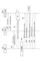
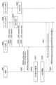
図4は、Conditional HO手順のシーケンスを示す図である。図4に示すように、ソースgNB100Aは、端末200から受信した測定報告に基づいて、ターゲットgNB100B, 100Cを見出すと、ターゲットgNB100B, 100Cに対して、Conditional HO要求(CHO request)を送信する(S11)。 (3.1) Conditional HO procedure FIG. 4 is a diagram showing the sequence of the Conditional HO procedure. As shown in FIG. 4, when the
ターゲットgNB100Bは、ソースgNB100AからCHO requestを受信すると、ターゲットgNB100B配下のセル(ターゲット候補セルという)の設定情報を含むCHO request応答(CHO request ACK)を、ソースgNB100Aに送信する(S13)。ターゲット候補セルの設定情報は、ターゲット候補セルの情報と、ターゲット候補セルへの遷移条件と含む。 When the
同様に、ターゲットgNB100Cは、ソースgNB100AからCHO requestを受信すると、ターゲットgNB100C配下のセル(ターゲット候補セルという)の設定情報を含むCHO request応答(CHO request ACK)を、ソースgNB100Aに送信する(S13)。ターゲット候補セルの設定情報は、ターゲット候補セルの情報と、ターゲット候補セルへの遷移条件と含む。 Similarly, when the target gNB100C receives a CHO request from the source gNB100A, it transmits a CHO request response (CHO request ACK) containing configuration information of a cell under the target gNB100C (referred to as a target candidate cell) to the source gNB100A (S13). . The target candidate cell setting information includes target candidate cell information and transition conditions to the target candidate cell.
ソースgNB100Aは、ターゲットgNB100B, 100CからCHO request ACKを受信すると、Conditional HO構成(CHO configuration)を含む無線リソース制御(RRC)再構成メッセージ(RRC Reconfiguration)を、端末200に送信する(S15)。CHO configurationは、ターゲットgNB100B, 100Cの各々から送信されたターゲット候補セルの設定情報を含む。 When the
端末200は、ソースgNB100AからCHO configurationを受信すると、Conditional HO条件(CHO条件)を監視する(S17)。具体的には、端末200は、各ターゲット候補セルの設定情報に含まれるターゲット候補セルへの遷移条件が満たされるか否かを判定する。 Upon receiving the CHO configuration from the
端末200は、端末200の移動などにより、ターゲット候補セルへの遷移条件が満たされると判定すると、ソースgNB100Aからハンドオーバコマンドを受信せずに、当該ターゲット候補セルへのハンドオーバ(HO)の開始を決定する(S19)。本実施形態では、端末200は、ターゲットgNB100B配下のターゲット候補セルへのHOの開始を決定する。遷移条件が満たされる遷移先のターゲット候補セルは、CHOセルとも呼称される。 When the terminal 200 determines that the transition conditions to the target candidate cell are satisfied due to movement of the terminal 200, etc., the terminal 200 decides to start handover (HO) to the target candidate cell without receiving a handover command from the
なお、ソースgNB100Aは、S13にて、ターゲットgNB100B, 100Cから、ターゲット候補セルの情報のみを受信してもよい。この場合、ソースgNB100Aは、S15にて、ターゲット候補セルの情報と、端末200がハンドオーバ(HO)をトリガする条件とを含むCHO configurationを、端末200に送信する。 Note that the
この場合、端末200は、S17にて、HOをトリガする条件が満たされるか否かを判定する。端末200は、端末200の移動などにより、HOをトリガする条件が満たされると判定すると、S19にて、遷移先のターゲット候補セルを決定し、当該ターゲット候補セルへのハンドオーバを開始する。端末200は、例えば、ソースgNB100Aによって付与された各ターゲット候補セルの優先度、各ターゲット候補セルの情報に含まれるセルの状態などに基づいて、遷移先のターゲット候補セルを決定する。 In this case, the terminal 200 determines in S17 whether the conditions for triggering HO are satisfied. When the terminal 200 determines that the conditions for triggering HO are satisfied due to movement of the terminal 200 or the like, in S19, the terminal 200 determines a target candidate cell to which to transition, and starts handover to the target candidate cell.
端末200は、ターゲットgNB100B配下のターゲット候補セルへのHOの開始を決定すると、ターゲットgNB100Bと端末200との間でランダムアクセス(RA)手順を実行して、ターゲットgNB100Bと端末200との間で同期を確立する(S21)。これにより、端末200は、ターゲットgNB100Bに接続する。 When the terminal 200 decides to start HO to the target candidate cell under the
端末200は、ターゲットgNB100Bに接続すると、RRC再構成完了メッセージ(RRC Reconfiguration Complete)をターゲットgNB100Bに送信する(S23)。 After connecting to the
(3.2)Conditional HO手順におけるRLFからの復帰
次に、Conditional HO手順におけるRLFからの復帰について説明する。最初に、従来のHO手順におけるRLFからの復帰について説明する。 (3.2) Return from RLF in Conditional HO procedure Next, return from RLF in Conditional HO procedure will be explained. First, the return from RLF in the conventional HO procedure will be explained.
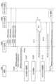
図5は、従来のHO手順におけるRLFからの復帰シーケンスを示す図である。図5に示すように、ソースgNB100Aは、端末200から受信した測定報告に基づいて、ターゲットgNB100Bを見出すと、ターゲットgNB100Bに対して、HO要求(HO request)を送信する(S51)。 FIG. 5 is a diagram showing a return sequence from RLF in a conventional HO procedure. As shown in FIG. 5, when the
ターゲットgNB100Bは、ソースgNB100AからHO requestを受信すると、ターゲットgNB100B配下のセル(ターゲットセルという)の情報を含むHO request応答(HO request ACK)を、ソースgNB100Aに送信する(S53)。 When the
ソースgNB100Aは、ターゲットgNB100BからHO request ACKを受信すると、ハンドオーバコマンド(HO command)を含むRRC再構成メッセージ(RRC Reconfiguration)を、端末200に送信する(S55)。HO commandは、ターゲットgNB100Bから送信されたターゲットセルの情報を含む。 When the
端末200は、ソースgNB100AからHO commandを受信すると、ターゲットgNB100Bと端末200との間でランダムアクセス(RA)手順を実行して、ターゲットgNB100Bと端末200との間で同期の確立を試みる。(S57)。 Upon receiving the HO command from the
端末200は、S57にて、RA手順の実行中に、RLFが発生して、RA手順に失敗すると、セル再選択を実行する(S59)。端末200は、ターゲットgNB100B配下のセルに再接続することを決定すると、ターゲットgNB100Bと端末200との間でRRC再確立(RRC Reestablishment)手順を行う。 If RLF occurs and the RA procedure fails in S57, the terminal 200 executes cell reselection (S59). When the terminal 200 decides to reconnect to the cell under the
具体的には、端末200は、RRC再確立要求メッセージ(RRC Reestablishment request)を、ターゲットgNB100Bに送信する(S61)。ターゲットgNB100Bは、端末200からRRC Reestablishment requestを受信すると、RRC再確立メッセージ(RRC Reestablishment)を端末200に送信する(S63)。RRC Reestablishmentは、ターゲットgNB100Bと端末200との間でRRCコネクションを再確立するために用いられる設定情報を含む。 Specifically, the terminal 200 transmits an RRC reestablishment request message (RRC Reestablishment request) to the
端末200は、ターゲットgNB100BからRRC Reestablishmentを受信すると、ターゲットgNB100Bと端末200との間でRRCコネクションを再確立し、RRC再確立完了メッセージ(RRC Reestablishment Complete)を送信する(S65)。 Upon receiving the RRC Reestablishment from the
S65にて、端末200は、RRC Reestablishment CompleteにRLF情報を含めて、RLF通知を行う。RLF情報は、端末200とターゲットgNB100Bとの間でRLFが発生したことを、ネットワーク側に通知するために、RRC Reestablishment Completeに含められる。 In S65, the terminal 200 includes RLF information in RRC Reestablishment Complete and sends an RLF notification. RLF information is included in RRC Reestablishment Complete in order to notify the network side that RLF has occurred between
ターゲットgNB100Bは、端末200からRRC Reestablishment Completeを受信すると、RRC Reconfigurationを端末200に送信する(S67)。端末200は、ターゲットgNB100BからRRC Reconfigurationを受信すると、RRCコネクションの再構成を実行し、RRC Reconfiguration CompleteをターゲットgNB100Bに送信する(S69)。 Upon receiving RRC Reestablishment Complete from
(3.2.1)動作例1
次に、Conditional HO手順におけるRLFからの復帰の動作例1について説明する。本動作例では、Conditional HO手順において、RLFが発生してRA手順が失敗した場合に、端末200は、遷移先のターゲット候補セル(CHOセル)を再選択し、RA手順を実行した後に、RRC再構成完了メッセージ(RRC Reconfiguration Complete)を用いて、RLFの発生をネットワーク側に通知する。 (3.2.1) Operation example 1
Next, operation example 1 of returning from RLF in the Conditional HO procedure will be described. In this operation example, in the Conditional HO procedure, if RLF occurs and the RA procedure fails, the terminal 200 reselects a transition destination target candidate cell (CHO cell), executes the RA procedure, and then performs RRC. The occurrence of RLF is notified to the network side using a reconfiguration complete message (RRC Reconfiguration Complete).
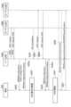
図6は、Conditional HO手順におけるRLFからの復帰シーケンス(動作例1)を示す図である。図6のS101~S109は、図4のS11~S19と同じ処理であるため、説明を省略する。 FIG. 6 is a diagram illustrating a return sequence from RLF (operation example 1) in the Conditional HO procedure. S101 to S109 in FIG. 6 are the same processes as S11 to S19 in FIG. 4, so the explanation will be omitted.
端末200は、ソースgNB100Aからハンドオーバコマンドを受信せずに、ターゲットgNB100B配下のターゲット候補セルへのHOの開始を決定すると、ターゲットgNB100Bと端末200との間でランダムアクセス(RA)手順を実行して、ターゲットgNB100Bと端末200との間で同期の確立を試みる(S111)。 When the terminal 200 decides to start HO to the target candidate cell under the
端末200は、S111にて、RA手順の実行中に、RLFが発生して、RA手順に失敗すると、遷移条件を満たす遷移先のターゲット候補セル(CHOセル)を再選択する(S113)。本実施形態では、端末200は、ターゲットgNB100B配下のターゲット候補セルを再選択する。 If an RLF occurs and the RA procedure fails in S111, the terminal 200 reselects a transition destination target candidate cell (CHO cell) that satisfies the transition conditions (S113). In this embodiment, the terminal 200 reselects a target candidate cell under the
端末200は、ターゲットgNB100B配下のターゲット候補セルを再選択すると、ターゲットgNB100Bと端末200との間でランダムアクセス(RA)手順を実行して、ターゲットgNB100Bと端末200との間で同期を確立する(S115)。これにより、端末200は、ターゲットgNB100Bに接続する。 When the terminal 200 reselects a target candidate cell under the
端末200は、ターゲットgNB100Bに接続すると、RRC再構成完了メッセージ(RRC Reconfiguration Complete)をターゲットgNB100Bに送信する(S117)。 After connecting to the
S117にて、端末200は、RRC Reconfiguration CompleteにRLF情報を含めて、RLF通知を行う。RLF情報は、端末200とターゲットgNB100Bとの間でRLFが発生したことを、ネットワーク側に通知するために、RRC Reconfiguration Completeに含められる。例えば、RLF情報は、1ビットで表される。この場合、例えば、RLFが発生した場合には、RLF情報として「1」が設定され、RLFが発生しない場合には、RLF情報として「0」が設定される。 In S117, the terminal 200 includes RLF information in RRC Reconfiguration Complete and sends an RLF notification. RLF information is included in RRC Reconfiguration Complete in order to notify the network side that RLF has occurred between
このように、RLF情報は、Conditional HO手順が完了したこと、すなわち、端末200がターゲット候補セルの設定情報を適用したことを示すメッセージに含まれる。 In this way, the RLF information is included in a message indicating that the Conditional HO procedure has been completed, that is, that the terminal 200 has applied the configuration information of the target candidate cell.
S117にて、端末200は、RRC Reconfiguration Completeに、RLF情報とRLF検出情報とを含めてもよい。RLF検出情報は、例えば、RLFが検出されたセル(本実施形態では、ターゲットgNB100B配下のセル)の識別子などのセル情報、RLFを検出した端末200の位置情報(グローバル・ナビゲーション・サテライト・システム(GNSS)情報など)、RLFが検出された無線アクセス技術(RAT)情報、RLFが検出された際に使用されていた周波数情報、RLFが検出された際に使用されていた帯域幅部分(BWP)情報、及びRLFが検出された位置(グローバル・ポジショニング・システム(GPS)情報など)のうち、少なくとも1つを含む。 In S117, terminal 200 may include RLF information and RLF detection information in RRC Reconfiguration Complete. The RLF detection information includes, for example, cell information such as the identifier of the cell where the RLF was detected (in this embodiment, the cell under the
なお、ソースgNB100Aは、S13と同様に、S103にて、ターゲットgNB100B, 100Cから、ターゲット候補セルの情報のみを受信してもよい。この場合、端末200は、S113にて、ソースgNB100Aによって付与された各ターゲット候補セルの優先度、各ターゲット候補セルの情報に含まれるセルの状態などに基づいて、遷移先のターゲット候補セル(CHOセル)を再選択する。 Note that, similar to S13, the
上述したように、CHOセルの再選択を用いてRLFから復帰する場合、端末200は、RRC Reestablishment手順を行うことなく、ターゲットgNBに遷移し、RLFから早期に復帰することができる。 As described above, when returning from RLF using CHO cell reselection, terminal 200 can transition to the target gNB and return from RLF early without performing the RRC Reestablishment procedure.
(3.2.2)動作例2
次に、Conditional HO手順におけるRLFからの復帰の動作例2について説明する。本動作例では、動作例1にて、端末200が、S105にて、ソースgNB100AからRRC Reconfigurationを受信すると、直ちに、RRC再構成完了メッセージ1(RRC Reconfiguration Complete 1)を送信する。 (3.2.2) Operation example 2
Next, a second operation example of returning from RLF in the Conditional HO procedure will be described. In this operation example, in operation example 1, when the terminal 200 receives RRC Reconfiguration from the
図7は、Conditional HO手順におけるRLFからの復帰シーケンス(動作例2)を示す図である。図7のS101~S115は、図6のS101~S115と同じ処理であるため、説明を省略する。 FIG. 7 is a diagram showing a return sequence from RLF (operation example 2) in the Conditional HO procedure. S101 to S115 in FIG. 7 are the same processes as S101 to S115 in FIG. 6, so the explanation will be omitted.
図7に示すように、端末200は、ソースgNB100AからRRC Reconfigurationを受信すると、直ちに、RRC Reconfiguration Complete1を送信する(S105a)。 As shown in FIG. 7, upon receiving RRC Reconfiguration from the
端末200は、S115のRA手順によりターゲットgNB100Bに接続すると、RRC再構成完了メッセージ2(RRC Reconfiguration Complete 2)又はRRCセットアップ完了メッセージ(RRC Setup Complete)をターゲットgNB100Bに送信する(S117a)。 When the terminal 200 connects to the
なお、RRC Reconfiguration Complete1及びRRC Reconfiguration Complete2は、RRC Reconfiguration Completeと同様の構成を有する。 Note that RRC Reconfiguration Complete1 and RRC Reconfiguration Complete2 have the same configuration as RRC Reconfiguration Complete.
S117aにて、端末200は、RRC Reconfiguration Complete 2又はRRC Setup CompleteにRLF情報を含めて、RLF通知を行う。また、S117aにて、端末200は、RRC Reconfiguration Complete 2又はRRC Setup Completeに、RLF情報とRLF検出情報とを含めてもよい。 In S117a, the terminal 200 includes the RLF information in
(3.2.3)動作例3
次に、Conditional HO手順におけるRLFからの復帰の動作例3について説明する。本動作例では、動作例1にて、Conditional HO手順において、RLFが発生してRA手順が失敗した場合に、端末200は、ターゲット候補セル以外の遷移先のセル(CHOセル以外の遷移先のセル)を再選択し、RRC Reestablishment手順を行う。 (3.2.3) Operation example 3
Next, a third operation example of returning from RLF in the Conditional HO procedure will be described. In this operation example, in operation example 1, when RLF occurs and the RA procedure fails in the Conditional HO procedure, the terminal 200 selects a transition destination cell other than the target candidate cell (a transition destination cell other than the CHO cell). cell) and perform the RRC Reestablishment procedure.
図8は、Conditional HO手順におけるRLFからの復帰シーケンス(動作例3)を示す図である。図8のS101~S111は、図6のS101~S111と同じ処理であるため、説明を省略する。 FIG. 8 is a diagram showing a return sequence from RLF in the Conditional HO procedure (operation example 3). S101 to S111 in FIG. 8 are the same processes as S101 to S111 in FIG. 6, so the explanation will be omitted.
なお、本動作例では、ソースgNB100Aは、端末200から受信した測定報告に基づいて、ターゲットgNB100Bのみを見出す。このため、ソースgNB100Aは、ターゲットgNB100Bに対して、CHO requestを送信し(S101)、ターゲットgNB100Bから、ターゲット候補セルの設定情報を含むCHO request ACKを受信する(S103)。 Note that in this operational example, the
端末200は、S111にて、RA手順の実行中に、RLFが発生して、RA手順に失敗すると、遷移条件を満たす遷移先のターゲット候補セル(CHOセル)を再選択する。しかしながら、端末200が、遷移条件を満たす遷移先のターゲット候補セルが存在しない場合、ターゲット候補セル以外の遷移先のセル(CHOセル以外の遷移先セル)を再選択する(S131)。本実施形態では、端末200は、ターゲットgNB100C配下のセルを再選択する。 In S111, if an RLF occurs during execution of the RA procedure and the RA procedure fails, the terminal 200 reselects a transition destination target candidate cell (CHO cell) that satisfies the transition conditions. However, if there is no transition destination target candidate cell that satisfies the transition conditions, the terminal 200 reselects a transition destination cell other than the target candidate cell (transition destination cell other than the CHO cell) (S131). In this embodiment, the terminal 200 reselects a cell under the
端末200は、ターゲットgNB100C配下のセルに再接続することを決定すると、ターゲットgNB100Cと端末200との間でRRC Reestablishment手順を行う。 When the terminal 200 decides to reconnect to the cell under the
具体的には、端末200は、RRC Reestablishment requestを、ターゲットgNB100Cに送信する(S133)。ターゲットgNB100Cは、端末200からRRC Reestablishment requestを受信すると、RRC Reestablishmentを端末200に送信する(S135)。RRC Reestablishmentは、ターゲットgNB100Cと端末200との間でRRCコネクションを再確立するために用いられる設定情報を含む。 Specifically, the terminal 200 transmits an RRC Reestablishment request to the
端末200は、ターゲットgNB100CからRRC Reestablishmentを受信すると、ターゲットgNB100Cと端末200との間でRRCコネクションを再確立し、RRC Reestablishment Completeを送信する(S137)。 Upon receiving RRC Reestablishment from
S137にて、端末200は、RRC Reestablishment CompleteにRLF情報を含めて、RLF通知を行う。また、S137にて、端末200は、RRC Reestablishment Completeに、RLF情報とRLF検出情報とを含めてもよい。 In S137, the terminal 200 includes RLF information in RRC Reestablishment Complete and sends an RLF notification. Furthermore, in S137, terminal 200 may include RLF information and RLF detection information in RRC Reestablishment Complete.
(3.2.4)情報要素(IE)
次に、上述したRLF通知に用いられる各メッセージのIEについて説明する。 (3.2.4) Information element (IE)
Next, the IE of each message used for the above-mentioned RLF notification will be explained.
図9は、VarRLF-Report内のIEを説明する図である。図9に示すように、端末200は、RLF情報をVarRLF-Report内のrlf-Report-r16に含める。なお、端末200は、RLF情報及びRLF検出情報をVarRLF-Report内のrlf-Report-r16に含めてもよい。 FIG. 9 is a diagram explaining the IE in VarRLF-Report. As shown in FIG. 9, the terminal 200 includes RLF information in rlf-Report-r16 within VarRLF-Report. Note that the terminal 200 may include RLF information and RLF detection information in rlf-Report-r16 within VarRLF-Report.
図10は、RRC Reconfiguration Complete内のIEを説明する図である。図10に示すように、端末200は、RLF情報がVarRLF-Reportに含まれている場合、図6のS117にてRLF情報をRRC Reconfiguration Complete内のrlf-InfoAvailable-r16に含める。なお、端末200は、RLF情報及びRLF検出情報をRRC Reconfiguration Complete内のrlf-InfoAvailable-r16に含めてもよい。 FIG. 10 is a diagram explaining the IE in RRC Reconfiguration Complete. As shown in FIG. 10, if the RLF information is included in VarRLF-Report, the terminal 200 includes the RLF information in rlf-InfoAvailable-r16 in RRC Reconfiguration Complete in S117 of FIG. Note that the terminal 200 may include RLF information and RLF detection information in rlf-InfoAvailable-r16 in RRC Reconfiguration Complete.
なお、上述したように、RRC Reconfiguration Complete2は、RRC Reconfiguration Completeと同様の構成を有する。従って、端末200は、RLF情報がVarRLF-Reportに含まれている場合、図7のS117aにてRLF情報をRRC Reconfiguration Complete2内のrlf-InfoAvailable-r16に含める。なお、端末200は、RLF情報及びRLF検出情報をRRC Reconfiguration Complete2内のrlf-InfoAvailable-r16に含めてもよい。 Note that, as described above, RRC Reconfiguration Complete2 has the same configuration as RRC Reconfiguration Complete. Therefore, if the RLF information is included in VarRLF-Report, the terminal 200 includes the RLF information in rlf-InfoAvailable-r16 in RRC Reconfiguration Complete2 in S117a of FIG. Note that the terminal 200 may include the RLF information and RLF detection information in rlf-InfoAvailable-r16 in RRC Reconfiguration Complete2.
図11A及び図11Bは、RRC Setup Complete内のIEを説明する図である。図11Aに示すように、端末200は、RLF情報がVarRLF-Reportに含まれている場合、図7のS117aにてRLF情報をRRC Setup Complete内のrlf-InfoAvailable-r16に含める。なお、端末200は、RLF情報及びRLF検出情報をRRC Setup Complete内のrlf-InfoAvailable-r16に含めてもよい。 FIG. 11A and FIG. 11B are diagrams explaining the IE in RRC Setup Complete. As shown in FIG. 11A, if the RLF information is included in VarRLF-Report, the terminal 200 includes the RLF information in rlf-InfoAvailable-r16 in RRC Setup Complete in S117a of FIG. Note that the terminal 200 may include the RLF information and RLF detection information in rlf-InfoAvailable-r16 in RRC Setup Complete.
図12は、RRC Reestablishment Complete内のIEを説明する図である。図12に示すように、端末200は、RLF情報がVarRLF-Reportに含まれている場合、図8のS137にてRLF情報をRRC Reestablishment Complete内のrlf-InfoAvailable-r16に含める。なお、端末200は、RLF情報及びRLF検出情報をRRC Reestablishment Complete内のrlf-InfoAvailable-r16に含めてもよい。 FIG. 12 is a diagram illustrating the IE in RRC Reestablishment Complete. As shown in FIG. 12, if the RLF information is included in VarRLF-Report, the terminal 200 includes the RLF information in rlf-InfoAvailable-r16 in RRC Reestablishment Complete in S137 of FIG. Note that the terminal 200 may include RLF information and RLF detection information in rlf-InfoAvailable-r16 in RRC Reestablishment Complete.
図13は、RRC Resume Complete内のIEを説明する図である。RRC Resume Completeは、後述の「(3.9)Conditional HO手順におけるRLF後の無線ベアラの再開」で説明するように、端末200が、無線ベアラの再開を指示するRRCメッセージの受信に基づいて、無線ベアラの再開を完了したことを、ネットワークに通知するのに用いられる。 FIG. 13 is a diagram illustrating the IE in RRC Resume Complete. RRC Resume Complete is based on the terminal 200 receiving an RRC message instructing to resume the radio bearer, as described in "(3.9) Resume of radio bearer after RLF in Conditional HO procedure" below. Used to notify the network that radio bearer resumption has been completed.
図13に示すように、端末200は、RLF情報がVarRLF-Reportに含まれている場合、RLFからの復帰後に無線ベアラの再開を完了したことを通知するRRC Resume Complete内のrlf-InfoAvailable-r16に、RLF情報を含めてもよい。なお、端末200は、RLF情報及びRLF検出情報をRRC Resume Complete内のrlf-InfoAvailable-r16に含めてもよい。 As shown in FIG. 13, if RLF information is included in VarRLF-Report, the terminal 200 receives rlf-InfoAvailable-r16 in RRC Resume Complete that notifies that the radio bearer has been resumed after returning from RLF. may include RLF information. Note that the terminal 200 may include the RLF information and RLF detection information in rlf-InfoAvailable-r16 in RRC Resume Complete.
図14は、UE Information Request内の情報要素(IE)を説明する図である。端末200は、ネットワークからの要求に基づいて、当該ネットワークに対して、RLFの発生を通知することができる。図14に示すように、ネットワークは、UE Information Request内のrlf-ReportReq-r16を用いて、RLF通知を端末200に要求する。 FIG. 14 is a diagram illustrating information elements (IE) within the UE Information Request. Based on a request from the network, the terminal 200 can notify the network of the occurrence of RLF. As shown in FIG. 14, the network requests RLF notification from the terminal 200 using rlf-ReportReq-r16 in the UE Information Request.
図15A~図15Cは、UE Information Response内のIEを説明する図である。端末200は、ネットワークから、UE Information Requestを用いて、RLF通知を要求されると、図15Aに示すように、RLF情報をUE Information Response内のrlf-Cause-r16に含める。なお、端末200は、RLF情報及びRLF検出情報をUE Information Response内のrlf-Cause-r16に含めてもよい。 FIGS. 15A to 15C are diagrams illustrating IEs within the UE Information Response. When the terminal 200 is requested to send an RLF notification from the network using the UE Information Request, the terminal 200 includes the RLF information in rlf-Cause-r16 in the UE Information Response, as shown in FIG. 15A. Note that the terminal 200 may include the RLF information and RLF detection information in rlf-Cause-r16 in the UE Information Response.
(3.2.5)その他
動作例1,2では、RLF情報を含むメッセージは、Conditional HO手順が完了したこと、すなわち、ターゲット候補セルの設定情報を適用したことを示すメッセージ(例えば、RRC Reconfiguration Complete, RRC Reconfiguration Complete 2, RRC Setup Complete)であったが、これに限定されない。 (3.2.5) Others In operation examples 1 and 2, the message containing RLF information is a message indicating that the Conditional HO procedure has been completed, that is, that the configuration information of the target candidate cell has been applied (for example, RRC Reconfiguration Complete,
例えば、RLF情報を含むメッセージは、遷移先のターゲットgNBに送信される最初のRRCメッセージでもよい。また、RLF情報を含むメッセージは、特定の識別子を有するメッセージでもよい。当該識別子として、トランザクション識別子、パケット・データ・コンバージェンス・プロトコル(PDCP)シーケンス番号(SN)、PDCPカウント値、無線リンク制御(RLC)シーケンス番号(SN)、又はハイブリッド・オートマチック・リピート・リクエスト処理(HARQ process)識別子が挙げられる。 For example, the message including RLF information may be the first RRC message sent to the transition destination target gNB. Furthermore, the message including RLF information may be a message having a specific identifier. The identifier may be a transaction identifier, a Packet Data Convergence Protocol (PDCP) sequence number (SN), a PDCP count value, a Radio Link Control (RLC) sequence number (SN), or a Hybrid Automatic Repeat Request Processing (HARQ). process) identifier.
また、端末200は、Conditional HO手順以外のタイミングで、RLF情報をネットワーク側に通知してもよい。 Further, the terminal 200 may notify the RLF information to the network side at a timing other than the Conditional HO procedure.
動作例1~3では、端末200は、RLF情報及びRLF検出情報を、同一のメッセージに含めたが、これに限定されず、これらの情報を異なるメッセージに含めてもよい。また、端末200は、ネットワークから指示がある場合に、RLF情報をメッセージに含めてもよい。同様に、端末200は、ネットワークから指示がある場合に、RLF検出情報をメッセージに含めてもよい。 In operation examples 1 to 3, the terminal 200 includes RLF information and RLF detection information in the same message, but the present invention is not limited to this, and these pieces of information may be included in different messages. Furthermore, the terminal 200 may include RLF information in the message when instructed to do so by the network. Similarly, the terminal 200 may include RLF detection information in a message when instructed to do so by the network.
複数のRLFが発生した場合、端末200は、複数のRLF検出情報を同一のメッセージに含めて、遷移先のターゲットgNBに送信してもよい。また、端末200は、所定数のRLF検出情報(例えば、1つのRLF検出情報)のみを同一のメッセージに含めて、遷移先のターゲットgNBに送信してもよい。 When multiple RLFs occur, the terminal 200 may include multiple pieces of RLF detection information in the same message and transmit it to the transition destination target gNB. Furthermore, the terminal 200 may include only a predetermined number of RLF detection information (for example, one RLF detection information) in the same message and transmit it to the transition destination target gNB.
複数のRLFが発生した場合、端末200は、複数のRLF検出情報に優先度を付与してもよい。例えば、端末200は、遷移先のターゲットgNB配下のセルで使用されている周波数と同じ周波数でRLFを検出した場合には、当該周波数の情報を含むRLF検出情報には高優先度を付与する。また、端末200は、ネットワークから指定された優先度で、複数のRLF検出情報を、遷移先のターゲットgNBに送信してもよい。 When multiple RLFs occur, the terminal 200 may give priority to the multiple RLF detection information. For example, when the terminal 200 detects an RLF on the same frequency as the frequency used in a cell under the target gNB of the transition destination, a high priority is given to the RLF detection information including information on the frequency. Furthermore, the terminal 200 may transmit a plurality of pieces of RLF detection information to the transition destination target gNB with a priority specified by the network.
また、複数のRLF検出情報を同一のメッセージに含めると、当該メッセージが許容する最大サイズを超える場合には、端末200は、当該メッセージから、一部のRLF検出情報を削除してもよい。この場合、端末200は、一部のRLF検出情報を削除したことを、遷移先のターゲットgNBに通知してもよい。 Further, if including multiple pieces of RLF detection information in the same message exceeds the maximum allowable size of the message, the terminal 200 may delete some of the RLF detection information from the message. In this case, the terminal 200 may notify the transition destination target gNB that some RLF detection information has been deleted.
さらに、端末200は、複数のRLF検出情報を含むメッセージを作成した後に、再度RLFを検出する場合には、当該メッセージを作成し直してもよい。 Furthermore, if the terminal 200 detects RLF again after creating a message including a plurality of pieces of RLF detection information, it may create the message again.
(3.3)Conditional HO手順におけるRRC Reconfiguration Complete送信タイミング
次に、Conditional HO手順におけるRRC Reconfiguration Complete送信タイミングについて説明する。図4に示したConditional HO手順では、端末200は、RA手順に成功した場合に、RRC Reconfiguration Completeの送信を実行する。これに対して、本動作では、端末200は、RRC Reconfigurationを受信すると、直ちにRRC Reconfiguration Completeの送信を実行する。すなわち、端末200は、RA手順の開始前に、RRC Reconfiguration Completeの送信を実行する。 (3.3) RRC Reconfiguration Complete transmission timing in Conditional HO procedure Next, the RRC Reconfiguration Complete transmission timing in the Conditional HO procedure will be described. In the Conditional HO procedure shown in FIG. 4, the terminal 200 transmits RRC Reconfiguration Complete when the RA procedure is successful. In contrast, in this operation, upon receiving RRC Reconfiguration, terminal 200 immediately executes transmission of RRC Reconfiguration Complete. That is, the terminal 200 transmits RRC Reconfiguration Complete before starting the RA procedure.
図16は、Conditional HO手順におけるRRC Reconfiguration Complete送信シーケンスを示す図である。図16のS151~S155は、図4のS11~S15と同じ処理であるため、説明を省略する。 FIG. 16 is a diagram showing an RRC Reconfiguration Complete transmission sequence in the Conditional HO procedure. S151 to S155 in FIG. 16 are the same processes as S11 to S15 in FIG. 4, so the explanation will be omitted.
端末200は、ソースgNB100Aから、CHO configurationを含むRRC Reconfigurationを受信すると、直ちに、ターゲット候補セルの設定情報を取得して、RRC Reconfiguration Complete1をソースgNB100Aに送信する(S155a)。 Upon receiving the RRC Reconfiguration including the CHO configuration from the
端末200は、RRC Reconfiguration Complete1をソースgNB100Aに送信すると、CHO条件を監視する(S157)。具体的には、端末200は、各ターゲット候補セルの設定情報に含まれるターゲット候補セルへの遷移条件が満たされるか否かを判定する。 After transmitting RRC Reconfiguration Complete1 to the
RRC処理を並行して実行すると無線基地局側の処理が複雑になるため、端末200は、ターゲット候補セルの設定情報を変更する場合、RRCコネクションの再構成が完了したことを通知するRRC Reconfiguration Completeを受信した後に、RRC Reconfigurationを用いて、当該変更を通知する必要がある。 If RRC processing is executed in parallel, the processing on the radio base station side becomes complicated, so when changing the configuration information of the target candidate cell, the terminal 200 sends an RRC Reconfiguration Complete notification to notify that the reconfiguration of the RRC connection is completed. After receiving the change, it is necessary to notify the change using RRC Reconfiguration.
このため、ソースgNB100Aは、ターゲット候補セルの設定情報を変更する場合、S155aにて、端末200からRRC Reconfiguration Complete1を受信した後に、RRC Reconfigurationを用いて、ターゲット候補セルの設定情報の変更を、端末200に通知する(S159)。 Therefore, when changing the configuration information of the target candidate cell, the
S159にて、ソースgNB100Aは、変更されたターゲット候補セルの設定情報を、RRC Reconfigurationに含める。なお、ソースgNB100Aは、変更されたターゲット候補セルの設定情報と、S155にて送信したターゲット候補セルの設定情報との差分を、新規のRRC Reconfigurationに含めてもよい。 In S159, the
S155で送信されるRRC Reconfigurationは、第1の設定メッセージとも呼称される。S155aで送信されるRRC Reconfiguration Complete1は、第1の設定メッセージに対する完了メッセージとも呼称される。S159で送信されるRRC Reconfigurationは、第2の設定メッセージとも呼称される。 The RRC Reconfiguration sent in S155 is also called a first configuration message. RRC Reconfiguration Complete1 transmitted in S155a is also called a completion message for the first configuration message. The RRC Reconfiguration sent in S159 is also called a second configuration message.
端末200は、ソースgNB100Aから、RRC Reconfigurationを受信すると、直ちに、変更されたターゲット候補セルの設定情報を取得して、RRC Reconfiguration Complete1をソースgNB100Aに送信する(S159a)。端末200は、変更されたターゲット候補セルの設定情報に基づいて、S155にて取得したターゲット候補セルの設定情報を更新する。 Upon receiving RRC Reconfiguration from
端末200は、端末200の移動などにより、ターゲット候補セルへの遷移条件が満たされると判定すると、ソースgNB100Aからハンドオーバコマンドを受信せずに、当該ターゲット候補セルへのハンドオーバ(HO)の開始を決定する(S161)。本実施形態では、端末200は、ターゲットgNB100B配下のターゲット候補セルへのHOの開始を決定する。 When the terminal 200 determines that the transition conditions to the target candidate cell are satisfied due to movement of the terminal 200, etc., the terminal 200 decides to start handover (HO) to the target candidate cell without receiving a handover command from the
端末200は、ターゲットgNB100B配下のターゲット候補セルへのHOの開始を決定すると、ターゲットgNB100Bと端末200との間でランダムアクセス(RA)手順を実行して、ターゲットgNB100Bと端末200との間で同期を確立する(S163)。これにより、端末200は、ターゲットgNB100Bに接続する。 When the terminal 200 decides to start HO to the target candidate cell under the
端末200は、ターゲットgNB100Bに接続するとRRC Reconfiguration Complete2又はRRC Setup CompleteをターゲットgNB100Bに送信する(S165)。 When the terminal 200 connects to the
なお、S159にて、ソースgNB100Aは、ターゲット候補セルの設定情報を変更するために、RRC Reconfigurationを端末200に送信しているが、これに限定されない。例えば、ソースgNB100Aは、ターゲット候補セルの設定情報の他に、端末200の構成(UE configuration)を変更するために、RRC Reconfigurationを端末200に送信してもよい。 Note that in S159, the
この場合、ソースgNB100Aは、変更されたUE configurationを、RRC Reconfigurationに含める。なお、ソースgNB100Aは、変更されたUE configurationと、先に送信したUE configurationとの差分を、RRC Reconfigurationに含めてもよい。 In this case, the
(3.4)Conditional HO手順におけるHO中止
次に、Conditional HO手順におけるHO中止について説明する。本動作では、ターゲットgNBが、ターゲット候補セルの設定情報をソースgNBに送信した後に、当該ターゲット候補セルの設定情報の削除を、ソースgNBに指示する。本実施形態では、ターゲットgNB100Bが、ターゲット候補セルの設定情報の削除を、ソースgNB100Aに指示する。 (3.4) HO cancellation in Conditional HO procedure Next, HO cancellation in Conditional HO procedure will be explained. In this operation, the target gNB transmits the configuration information of the target candidate cell to the source gNB, and then instructs the source gNB to delete the configuration information of the target candidate cell. In this embodiment, the
(3.4.1)動作例1
最初に、Conditional HO手順におけるHO中止の動作例1について説明する。図17は、Conditional HO手順におけるHO中止シーケンス(動作例1)を示す図である。図17に示すS201~S207は、図16に示すS151~S157と同じ処理であるため、説明を省略する。 (3.4.1) Operation example 1
First, operation example 1 of HO cancellation in the Conditional HO procedure will be described. FIG. 17 is a diagram showing an HO abort sequence (operation example 1) in the Conditional HO procedure. S201 to S207 shown in FIG. 17 are the same processes as S151 to S157 shown in FIG. 16, so the explanation will be omitted.
なお、S203で送信されるCHO request ACKは、第1のメッセージとも呼称される。S209で送信されるHO cancellationは、第2のメッセージとも呼称される。 Note that the CHO request ACK transmitted in S203 is also called a first message. The HO cancellation sent in S209 is also called a second message.
ターゲットgNB100Bは、配下のターゲット候補セルが、端末200が遷移するのに相応しくない状態にあることを識別すると、HO削除メッセージ(HO cancellation)をソースgNB100Aに送信する(S209)。 When the
具体的には、ターゲットgNB100Bは、配下のターゲット候補セルで負荷が増大し、当該ターゲット候補セルが、端末200が遷移するのに相応しくない状態にあることを決定すると、S209にてHO cancellationを送信してもよい。 Specifically, when the
この場合、多数の端末が、ターゲットgNB100B配下のターゲット候補セルに遷移して、接続端末の数が、当該ターゲット候補セルが許容する接続端末の最大数を超えると、ターゲットgNB100Bは、当該ターゲット候補セルが、端末200が遷移するのに相応しくない状態にあることを決定してもよい。 In this case, if a large number of terminals transition to a target candidate cell under the
例えば、呼受付制御(CAC)において、ターゲットgNB100B配下のターゲット候補セルにおいて、接続端末の数が、UEコンテキストの最大数を超えると、ターゲットgNB100Bは、当該ターゲット候補セルが、端末200が遷移するのに相応しくない状態にあることを決定する。 For example, in call admission control (CAC), if the number of connected terminals exceeds the maximum number of UE contexts in a target candidate cell under the
また、端末200が、ターゲットgNB100B配下のターゲット候補セルの設定情報に基づいて、規定された時間内に、当該ターゲット候補セルに遷移しない場合(例えば、端末200が、規定された時間を超えても、インアクティブ状態にある場合)、ターゲットgNB100Bは、S209にてHO cancellationを送信してもよい。 Additionally, if the terminal 200 does not transition to the target candidate cell within a specified time based on the configuration information of the target candidate cell under the
さらに、ターゲットgNB100Bが、ソースgNB以外のgNB又はng-eNBから、UEコンテキスト解放(UE context release)を受信した場合、ターゲットgNB100Bは、S209にてHO cancellationを送信してもよい。 Furthermore, when the
なお、S209にて、ターゲットgNB100Bは、ソースgNB100Aに対して、直接HO cancellationを送信してもよい。この場合、HO cancellationの送信には、例えば、Xnシグナリングが用いられる。代わりに、ターゲットgNB100Bは、ソースgNB100Aに対して、コアネットワークを介して、HO cancellationを送信してもよい。この場合、HO cancellationの送信には、例えば、NGシグナリングが用いられる。 Note that in S209, the
ソースgNB100Aは、ターゲットgNB100BからHO cancellationを受信すると、S205aにて、端末200からRRC Reconfiguration Complete1を受信した後に、RRC Reconfigurationを用いて、ターゲット候補セルの設定情報の変更を、端末200に通知する(S211)。 When the
具体的には、ソースgNB100Aは、ターゲットgNB100B配下のターゲット候補セルの設定情報を削除することを指示する情報を、RRC Reconfigurationに含める。なお、ソースgNB100Aは、ターゲットgNB100B配下のターゲット候補セルの設定情報を削除したCHO configurationを、RRC Reconfigurationに含めてもよい。 Specifically, the
端末200は、ソースgNB100Aから、RRC Reconfigurationを受信すると、直ちに、RRC Reconfiguration Complete1をソースgNB100Aに送信する(S211a)。端末200は、RRC Reconfigurationの受信に基づいて、ターゲットgNB100B配下のターゲット候補セルの設定情報を削除する。 Upon receiving RRC Reconfiguration from
端末200は、端末200の移動などにより、ターゲット候補セルへの遷移条件が満たされると判定すると、ソースgNB100Aからハンドオーバコマンドを受信せずに、当該ターゲット候補セルへのハンドオーバ(HO)の開始を決定する(S213)。本実施形態では、端末200は、ターゲットgNB100C配下のターゲット候補セルへのHOの開始を決定する。 When the terminal 200 determines that the transition conditions to the target candidate cell are satisfied due to movement of the terminal 200, etc., the terminal 200 decides to start handover (HO) to the target candidate cell without receiving a handover command from the
端末200は、ターゲットgNB100C配下のターゲット候補セルへのHOの開始を決定すると、ターゲットgNB100Cと端末200との間でランダムアクセス(RA)手順を実行して、ターゲットgNB100Cと端末200との間で同期を確立する(S215)。これにより、端末200は、ターゲットgNB100Cに接続する。 When the terminal 200 decides to start HO to the target candidate cell under the target gNB100C, it executes a random access (RA) procedure between the target gNB100C and the terminal 200, and synchronizes the target gNB100C and the terminal 200. Establish (S215). Thereby, the terminal 200 connects to the
端末200は、ターゲットgNB100Cに接続するとRRC Reconfiguration Complete2又はRRC Setup CompleteをターゲットgNB100Cに送信する(S217)。 When the terminal 200 connects to the
(3.4.2)動作例2
次に、Conditional HO手順におけるHO中止の動作例2について説明する。図18は、Conditional HO手順におけるHO中止シーケンス(動作例2)を示す図である。図18に示すS231~S239は、図17に示すS201~S209と同じ処理であるため、説明を省略する。 (3.4.2) Operation example 2
Next, a second operation example of HO cancellation in the Conditional HO procedure will be described. FIG. 18 is a diagram showing an HO abort sequence (operation example 2) in the Conditional HO procedure. S231 to S239 shown in FIG. 18 are the same processes as S201 to S209 shown in FIG. 17, so the explanation will be omitted.
なお、本動作例では、ソースgNB100Aは、端末200から受信した測定報告に基づいて、ターゲットgNB100Bのみを見出す。このため、ソースgNB100Aは、ターゲットgNB100Bに対して、CHO requestを送信し(S231)、ターゲットgNB100Bから、ターゲット候補セルの設定情報を含むCHO request ACKを受信する(S233)。 Note that in this operational example, the
ソースgNB100Aは、ターゲットgNB100BからHO cancellationを受信した後、ソースgNB100Aの周囲に存在するターゲットgNB100Cを見出すと、ターゲットgNB100Cに対して、CHO requestを送信する(S241)。 After receiving the HO cancellation from the
ターゲットgNB100Cは、ソースgNB100AからCHO requestを受信すると、ターゲットgNB100C配下のターゲット候補セルの設定情報を含むCHO request ACKを、ソースgNB100Aに送信する(S243)。 When the
ソースgNB100Aは、ターゲットgNB100BからHO cancellationを受信し、かつ、ターゲットgNB100CからCHO request ACKを受信すると、S235aにて、端末200からRRC Reconfiguration Complete1を受信した後に、RRC Reconfigurationを用いて、ターゲット候補セルの設定情報の変更を、端末200に通知する(S245)。 When the
具体的には、ソースgNB100Aは、ターゲットgNB100B配下のターゲット候補セルの設定情報を削除し、かつ、ターゲットgNB100C配下のターゲット候補セルの設定情報を含むCHO configurationを、RRC Reconfigurationに含める。 Specifically, the
端末200は、ソースgNB100Aから、RRC Reconfigurationを受信すると、直ちに、RRC Reconfiguration Complete1をソースgNB100Aに送信する(S245a)。端末200は、RRC Reconfigurationの受信に基づいて、ターゲットgNB100C配下のターゲット候補セルの設定情報を含むCHO configurationを適用する。 Upon receiving RRC Reconfiguration from
端末200は、端末200の移動などにより、ターゲット候補セルへの遷移条件が満たされると判定すると、ソースgNB100Aからハンドオーバコマンドを受信せずに、当該ターゲット候補セルへのハンドオーバ(HO)の開始を決定する(S247)。本実施形態では、端末200は、ターゲットgNB100C配下のターゲット候補セルへのHOの開始を決定する。 When the terminal 200 determines that the transition conditions to the target candidate cell are satisfied due to movement of the terminal 200, etc., the terminal 200 decides to start handover (HO) to the target candidate cell without receiving a handover command from the
端末200は、ターゲットgNB100C配下のターゲット候補セルへのHOの開始を決定すると、ターゲットgNB100Cと端末200との間でランダムアクセス(RA)手順を実行して、ターゲットgNB100Cと端末200との間で同期を確立する(S249)。これにより、端末200は、ターゲットgNB100Cに接続する。 When the terminal 200 decides to start HO to the target candidate cell under the target gNB100C, it executes a random access (RA) procedure between the target gNB100C and the terminal 200, and synchronizes the target gNB100C and the terminal 200. Establish (S249). Thereby, the terminal 200 connects to the
端末200は、ターゲットgNB100Cに接続するとRRC Reconfiguration Complete2又はRRC Setup CompleteをターゲットgNB100Cに送信する(S251)。 When the terminal 200 connects to the
(3.5)Conditional HO手順におけるHO変更
次に、Conditional HO手順におけるHO変更について説明する。本動作では、ターゲットgNBが、ターゲット候補セルの設定情報をソースgNBに送信した後に、当該ターゲット候補セルの設定情報の変更を、ソースgNBに指示する。本実施形態では、ターゲットgNB100Bが、ターゲット候補セルの設定情報の変更を、ソースgNB100Aに指示する。 (3.5) HO change in Conditional HO procedure Next, HO change in Conditional HO procedure will be explained. In this operation, the target gNB transmits the configuration information of the target candidate cell to the source gNB, and then instructs the source gNB to change the configuration information of the target candidate cell. In this embodiment, the
(3.5.1)動作例1
最初に、Conditional HO手順におけるHO変更の動作例1について説明する。図19は、Conditional HO手順におけるHO変更シーケンス(動作例1)を示す図である。図19に示すS301, S303, S309~S315は、図4に示すS11, S13, S17~S23と同じ処理であるため、説明を省略する。 (3.5.1) Operation example 1
First, operation example 1 of changing HO in the Conditional HO procedure will be described. FIG. 19 is a diagram showing an HO change sequence (operation example 1) in the Conditional HO procedure. S301, S303, S309 to S315 shown in FIG. 19 are the same processes as S11, S13, and S17 to S23 shown in FIG. 4, so the explanation will be omitted.
なお、S303で送信されるCHO request ACKは、第1のメッセージとも呼称される。S305で送信されるHO modificationは、第2のメッセージとも呼称される。 Note that the CHO request ACK transmitted in S303 is also called a first message. The HO modification sent in S305 is also called a second message.
図19に示すように、ターゲットgNB100Bは、S303にて、CHO request ACKを用いて、配下のターゲット候補セルの設定情報を、ソースgNB100Aに送信した後、当該ターゲット候補セルの状態が変化したことを識別すると、HO変更メッセージ(HO modification)をソースgNB100Aに送信する(S305)。 As shown in FIG. 19, in S303, the
具体的には、ターゲットgNB100Bは、配下のターゲット候補セルで負荷状態が変化し、当該ターゲット候補セルへの遷移条件を変更する必要があると決定すると、S305にてHO modificationを送信してもよい。 Specifically, when the
なお、S305にて、ターゲットgNB100Bは、ソースgNB100Aに対して、直接HO modificationを送信してもよい。この場合、HO modificationの送信には、例えば、Xnシグナリングが用いられる。代わりに、ターゲットgNB100Bは、ソースgNB100Aに対して、コアネットワークを介して、HO modificationを送信してもよい。この場合、HO modificationの送信には、例えば、NGシグナリングが用いられる。 Note that in S305, the
ソースgNB100Aは、ターゲットgNB100BからHO modificationを受信すると、ターゲットgNB100B配下のターゲット候補セルの設定情報を変更した上で、CHO configurationを含むRRC Reconfigurationを、端末200に送信する(S307)。 When the
(3.5.2)動作例2
次に、Conditional HO手順におけるHO変更の動作例2について説明する。図20は、Conditional HO手順におけるHO変更シーケンス(動作例2)を示す図である。図20に示すS301~S313は、図19に示すS301~S313と同じ処理であるため、説明を省略する。 (3.5.2) Operation example 2
Next, a second operation example of changing HO in the Conditional HO procedure will be described. FIG. 20 is a diagram showing an HO change sequence (operation example 2) in the Conditional HO procedure. S301 to S313 shown in FIG. 20 are the same processes as S301 to S313 shown in FIG. 19, so the explanation will be omitted.
図20に示すように、端末200は、ソースgNB100AからRRC Reconfigurationを受信すると、直ちに、RRC Reconfiguration Complete1を送信する(S307a)。 As shown in FIG. 20, upon receiving RRC Reconfiguration from
端末200は、S313のRA手順によりターゲットgNB100Bに接続すると、RRC Reconfiguration Complete 2又はRRC Setup CompleteをターゲットgNB100Bに送信する(S315a)。 When the terminal 200 connects to the
(3.5.3)動作例3
次に、Conditional HO手順におけるHO変更の動作例3について説明する。図21は、Conditional HO手順におけるHO変更シーケンス(動作例3)を示す図である。図21に示すS301, S303, S307, S307a, S309は、図20に示すS301, S303, S307, S307a, S309と同じ処理であるため、説明を省略する。 (3.5.3) Operation example 3
Next, a third operation example of changing HO in the Conditional HO procedure will be described. FIG. 21 is a diagram showing an HO change sequence (operation example 3) in the Conditional HO procedure. S301, S303, S307, S307a, and S309 shown in FIG. 21 are the same processes as S301, S303, S307, S307a, and S309 shown in FIG. 20, and therefore the description thereof will be omitted.
図21に示すように、ターゲットgNB100Bは、配下のターゲット候補セルの状態が変化したことを識別すると、HO modificationをソースgNB100Aに送信する(S331)。 As shown in FIG. 21, when the
ソースgNB100Aは、ターゲットgNB100BからHO modificationを受信すると、S307aにて、端末200からRRC Reconfiguration Complete1を受信した後に、RRC Reconfigurationを用いて、ターゲット候補セルの設定情報の変更を、端末200に通知する(S333)。 When the
具体的には、ソースgNB100Aは、ターゲットgNB100B配下のターゲット候補セルの設定情報を変更したCHO configurationを、RRC Reconfigurationに含める。 Specifically, the
端末200は、ソースgNB100Aから、RRC Reconfigurationを受信すると、直ちに、RRC Reconfiguration Complete1をソースgNB100Aに送信する(S333a)。端末200は、RRC Reconfigurationの受信に基づいて、ターゲットgNB100B配下のターゲット候補セルの設定情報を変更する。 Upon receiving RRC Reconfiguration from
端末200は、端末200の移動などにより、ターゲット候補セルへの遷移条件が満たされると判定すると、ソースgNB100Aからハンドオーバコマンドを受信せずに、当該ターゲット候補セルへのハンドオーバ(HO)の開始を決定する(S335)。本実施形態では、端末200は、ターゲットgNB100B配下のターゲット候補セルへのHOの開始を決定する。 When the terminal 200 determines that the transition conditions to the target candidate cell are satisfied due to movement of the terminal 200, etc., the terminal 200 decides to start handover (HO) to the target candidate cell without receiving a handover command from the
端末200は、ターゲットgNB100B配下のターゲット候補セルへのHOの開始を決定すると、ターゲットgNB100Bと端末200との間でランダムアクセス(RA)手順を実行して、ターゲットgNB100Bと端末200との間で同期を確立する(S337)。これにより、端末200は、ターゲットgNB100Bに接続する。 When the terminal 200 decides to start HO to the target candidate cell under the
端末200は、ターゲットgNB100Bに接続するとRRC Reconfiguration Complete2又はRRC Setup CompleteをターゲットgNB100Bに送信する(S339)。 When the terminal 200 connects to the
(3.6)Conditional HO手順におけるRRC Reconfigurationの構成
次に、Conditional HO手順におけるRRC Reconfigurationの構成について説明する。本構成では、RRC Reconfigurationは、ターゲットgNB100B配下のターゲット候補セルの設定情報、及びターゲットgNB100C配下のターゲット候補セルの設定情報を格納する。なお、「複数のターゲット候補セルの設定情報をRRC Reconfigurationに格納する」ことは、「複数のターゲット候補セルの設定情報をRRC Reconfigurationにカプセル化する」とも表現される。 (3.6) Configuration of RRC Reconfiguration in Conditional HO procedure Next, the configuration of RRC Reconfiguration in Conditional HO procedure will be described. In this configuration, RRC Reconfiguration stores configuration information of target candidate cells under
最初に、ターゲット候補セルの設定情報をカプセル化する動作フローを説明する。図22は、ターゲット候補セルの設定情報をカプセル化する動作フローを示す図である。図22に示すように、ソースgNB100Aは、CHO requestをターゲットgNB100B, 100Cに送信する(S350)。 First, an operation flow for encapsulating configuration information of a target candidate cell will be described. FIG. 22 is a diagram showing an operation flow for encapsulating configuration information of a target candidate cell. As shown in FIG. 22, the
ソースgNB100Aは、ターゲットgNB100B, 100Cの各々から、ターゲット候補セルの設定情報を受信する(S353)と、当該ターゲット候補セルの設定情報を、RRC Reconfigurationにカプセル化する(S355)。 When the
ソースgNB100Aは、複数のターゲット候補セルの設定情報を、RRC Reconfigurationにカプセル化すると、当該RRC Reconfigurationを端末200に送信する(S357)。 When the
(3.6.1)構成例1
次に、ターゲット候補セルの設定情報のカプセル化について詳細に説明する。図23は、Conditional HO手順におけるRRC Reconfigurationの構成(構成例1)を説明する図である。 (3.6.1) Configuration example 1
Next, encapsulation of configuration information of a target candidate cell will be described in detail. FIG. 23 is a diagram illustrating the configuration (configuration example 1) of RRC Reconfiguration in the Conditional HO procedure.
図23に示すように、下りリンク専用制御チャネル(DL-DCCH)用メッセージ群には、RRC Reconfiguration, RRC再開メッセージ(RRC Resume), RRC解放メッセージ(RRC Release), RRC Reestablishment, セキュリティ・モード・コマンド(Security Mode Command)などが含まれる。 As shown in Figure 23, the message group for the downlink dedicated control channel (DL-DCCH) includes RRC Reconfiguration, RRC Resume message (RRC Resume), RRC Release message (RRC Release), RRC Reestablishment, and Security Mode Command. (Security Mode Command), etc.
DL-DCCHは、RRCコネクションを確立した端末200に使用される下りリンク専用制御チャネルである。端末200は、DL-DCCHを介して、上述したRRCメッセージなどを受信する。 DL-DCCH is a downlink dedicated control channel used by terminal 200 that has established an RRC connection.
本構成例では、従来のRRC Reconfiguration内に、新規の情報要素(IE)を設定して、ターゲットgNB100B配下のターゲット候補セルの設定情報、及びターゲットgNB100C配下のターゲット候補セルの設定情報を、当該IEに含める。 In this configuration example, a new information element (IE) is set in the conventional RRC Reconfiguration, and the configuration information of the target candidate cell under the target gNB100B and the configuration information of the target candidate cell under the target gNB100C are set in the IE. Include in
具体的には、従来のRRC Reconfiguration内に、新規IEとして、RRC再構成リスト(RRCReconfigurationList)が設定され、かつ、RRCReconfigurationList内に、configuration for cell1及びconfiguration for cell2が設定される。なお、configuration for cellの数は、2つには限定されない。 Specifically, an RRC reconfiguration list (RRCReconfigurationList) is set as a new IE in the conventional RRC Reconfiguration, and configuration for cell1 and configuration for cell2 are set in RRCReconfigurationList. Note that the number of configurations for cells is not limited to two.
このような構成において、ソースgNB100Aは、ターゲットgNB100Bから、ターゲットgNB100B配下のターゲット候補セルの設定情報を受信すると、当該ターゲット候補セルの設定情報をRRCReconfigurationList内のconfiguration for cell1に含める。同様に、ソースgNB100Aは、ターゲットgNB100Cから、ターゲットgNB100C配下のターゲット候補セルの設定情報を受信すると、当該ターゲット候補セルの設定情報をRRCReconfigurationList内のconfiguration for cell2に含める。 In such a configuration, when the
なお、RRCReconfigurationListは、CHO configurationとも呼称される。端末200は、ソースgNB100AからRRC Reconfigurationを受信すると、RRC Reconfiguration内のconfiguration for cell1及びconfiguration for cell2から、ターゲットgNB100B配下のターゲット候補セルの設定情報及びターゲットgNB100C配下のターゲット候補セルの設定情報を取得する。 Note that RRCReconfigurationList is also called CHO configuration. When the terminal 200 receives RRC Reconfiguration from the
ターゲット候補セルの設定情報として、ターゲット候補セルの情報、及びターゲット候補セルへの遷移条件の他に、次の情報のうち、少なくとも1つを含んでもよい。 The target candidate cell setting information may include at least one of the following information in addition to the target candidate cell information and the transition conditions to the target candidate cell.
測定条件
ターゲット候補セルの構成
セキュリティ情報(例えば、セキュリティ鍵の更新情報)
トランザクション識別子 Measurement conditions Target candidate cell configuration Security information (e.g. security key update information)
transaction identifier
(3.6.2)構成例2
図24は、Conditional HO手順におけるRRC Reconfigurationの構成(構成例2)を説明する図である。図24に示すように、DL-DCCH用メッセージには、RRC Reconfiguration, RRC Resume, RRC Release, RRC Reestablishment, Security Mode Command, RRC Reconfiguration1などが含まれる。 (3.6.2) Configuration example 2
FIG. 24 is a diagram illustrating the configuration of RRC Reconfiguration (configuration example 2) in the Conditional HO procedure. As shown in FIG. 24, the DL-DCCH messages include RRC Reconfiguration, RRC Resume, RRC Release, RRC Reestablishment, Security Mode Command, RRC Reconfiguration1, and the like.
RRC Reconfiguration1は、従来のRRC Reconfigurationとは異なる新規のメッセージであり、Conditional HO手順で用いられるRRC再構成メッセージである。なお、当該新規メッセージの呼称は、RRC Reconfiguration1には限定されない。本構成例では、RRC Reconfiguration1内に設定された情報要素(IE)に、ターゲットgNB100B配下のターゲット候補セルの設定情報、及びターゲットgNB100C配下のターゲット候補セルの設定情報を含める。
具体的には、新規のRRC Reconfiguration1内にRRC再構成リスト(RRCReconfigurationList)が設定され、かつ、RRCReconfigurationList内に、configuration for cell1及びconfiguration for cell2が設定される。なお、configuration for cellの数は、2つには限定されない。 Specifically, an RRC reconfiguration list (RRCReconfigurationList) is set in the new RRC Reconfiguration1, and configuration for cell1 and configuration for cell2 are set in RRCReconfigurationList. Note that the number of configurations for cells is not limited to two.
このような構成において、ソースgNB100Aは、ターゲットgNB100Bから、ターゲットgNB100B配下のターゲット候補セルの設定情報を受信すると、当該ターゲット候補セルの設定情報をRRCReconfigurationList内のconfiguration for cell1に含める。同様に、ソースgNB100Aは、ターゲットgNB100Cから、ターゲットgNB100C配下のターゲット候補セルの設定情報を受信すると、当該ターゲット候補セルの設定情報をRRCReconfigurationList内のconfiguration for cell2に含める。 In such a configuration, when the
端末200は、ソースgNB100AからRRC Reconfiguration1を受信すると、RRC Reconfiguration1内のconfiguration for cell1及びconfiguration for cell2から、ターゲットgNB100B配下のターゲット候補セルの設定情報及びターゲットgNB100C配下のターゲット候補セルの設定情報を取得する。 When the terminal 200 receives RRC Reconfiguration1 from the source gNB100A, it acquires the configuration information of the target candidate cell under the target gNB100B and the configuration information of the target candidate cell under the target gNB100C from configuration for cell1 and configuration for cell2 in RRC Reconfiguration1. .
(3.7)Conditional HO手順におけるトランザクションID付与
次に、Conditional HO手順におけるトランザクションID付与について説明する。本動作では、ソースgNB又はターゲットgNBが、Conditional HO手順で利用されるトランザクションIDの付与を実行する。 (3.7) Transaction ID assignment in Conditional HO procedure Next, transaction ID assignment in the Conditional HO procedure will be explained. In this operation, the source gNB or target gNB assigns a transaction ID to be used in the Conditional HO procedure.
(3.7.1)動作例1
最初に、Conditional HO手順におけるID付与の動作例1について説明する。本動作例では、ソースgNBが、Conditional HO手順で利用されるトランザクションIDの付与を実行する。 (3.7.1) Operation example 1
First, operation example 1 of ID assignment in the Conditional HO procedure will be described. In this operation example, the source gNB executes assignment of a transaction ID used in the Conditional HO procedure.
図25は、Conditional HO手順におけるID付与シーケンス(動作例1)を示す図である。図25に示すS401, S403, S409~S413は、図4に示すS11, S13, S17~S21と同じ処理であるため、説明を省略する。 FIG. 25 is a diagram showing an ID assignment sequence (operation example 1) in the Conditional HO procedure. S401, S403, S409 to S413 shown in FIG. 25 are the same processes as S11, S13, and S17 to S21 shown in FIG. 4, so the explanation will be omitted.
図25に示すように、ソースgNB100Aは、ターゲットgNB100B, 100CからCHO request ACKを受信すると、RRC ReconfigurationにCHO configurationを含めるとともに、RRC ReconfigurationにトランザクションIDを付与する(S405)。 As shown in FIG. 25, when the
具体的には、ソースgNB100Aは、RRC Reconfiguration内のRRCReconfigurationListに、ターゲットgNB100B配下のターゲット候補セルの識別情報及びターゲットgNB100C配下のターゲット候補セルの識別情報を含めるとともに、RRC Reconfiguration内の所定の情報要素(IE)にトランザクションIDを設定する(図23参照)。なお、RRCReconfigurationListは、CHO configurationとも呼称される。 Specifically, the
なお、ソースgNB100Aは、Conditional HOで用いられるRRC再構成メッセージであるRRC Reconfiguration1内のRRCReconfigurationListに、ターゲットgNB100B配下のターゲット候補セルの識別情報及びターゲットgNB100C配下のターゲット候補セルの識別情報を含めるとともに、RRC Reconfiguration1内の所定の情報要素(IE)にトランザクションIDを設定してもよい(図24参照)。 Note that the
トランザクションIDは、0~3のうちの1つの値でもよいし、固定値0でもよい。本実施形態では、トランザクションIDは、0~3のうちの1つの値をとる。 The transaction ID may be one value from 0 to 3, or may be a fixed value of 0. In this embodiment, the transaction ID takes one value from 0 to 3.
ソースgNB100Aは、RRC ReconfigurationにトランザクションIDを付与する代わりに、RRCReconfigurationに含まれるRRCReconfigurationList、すなわち、カプセル化されたターゲット候補セルの設定情報のグループにトランザクションIDを付与してもよい。 Instead of assigning a transaction ID to RRC Reconfiguration, the
ソースgNB100Aは、RRC Reconfigurationを設定すると、当該RRC Reconfigurationを、端末200に送信する(S407)。 After setting the RRC Reconfiguration, the
端末200は、ソースgNB100Aから、RRC Reconfigurationを受信すると、直ちに、ターゲット候補セルの設定情報を取得して、RRC Reconfiguration Complete1をソースgNB100Aに送信する(S407a)。 Upon receiving RRC Reconfiguration from
S407aにて、端末200は、ソースgNB100Aから受信したRRC Reconfigurationに付与されたトランザクションIDをRRC Reconfiguration Complete1に含める。 In S407a, the terminal 200 includes the transaction ID given to the RRC Reconfiguration received from the
端末200は、CHO条件の監視(S409)、ターゲットgNB100BへのHOの開始(S411)、及びターゲットgNB100Bと端末200との間でRA手順(S413)を実行し、ターゲットgNB100Bに接続するとRRC Reconfiguration Complete2をターゲットgNB100Bに送信する(S415)。 The terminal 200 monitors the CHO condition (S409), starts HO to the target gNB100B (S411), and executes the RA procedure (S413) between the target gNB100B and the terminal 200, and when connected to the target gNB100B, RRC Reconfiguration Complete2 is sent to the target gNB100B (S415).
(3.7.2)動作例2
次に、Conditional HO手順におけるID付与の動作例2について説明する。本動作例では、ターゲットgNBが、Conditional HO手順で利用されるトランザクションIDの付与を実行する。 (3.7.2) Operation example 2
Next, a second operation example of ID assignment in the Conditional HO procedure will be described. In this operation example, the target gNB executes assignment of a transaction ID used in the Conditional HO procedure.
図26は、Conditional HO手順におけるID付与シーケンス(動作例2)を示す図である。図26に示すS401, S437~S441は、図4に示すS11, S17~S21と同じ処理であるため、説明を省略する。 FIG. 26 is a diagram showing an ID assignment sequence (operation example 2) in the Conditional HO procedure. S401 and S437 to S441 shown in FIG. 26 are the same processes as S11 and S17 to S21 shown in FIG. 4, so the explanation will be omitted.
図26に示すように、ターゲットgNB100Bは、ソースgNB100AからCHO requestを受信すると、CHO request ACKに、ターゲットgNB100B配下のターゲット候補セルの設定情報を含めるとともに、当該ターゲット候補セルの設定情報にトランザクションIDを付与する(S431)。具体的には、ターゲットgNB100Bは、ターゲット候補セルの設定情報に、当該トランザクションIDを含める。 As shown in FIG. 26, when the
同様に、ターゲットgNB100Cは、ソースgNB100AからCHO requestを受信すると、CHO request ACKに、ターゲットgNB100C配下のターゲット候補セルの設定情報を含めるとともに、当該ターゲット候補セルの設定情報にトランザクションIDを付与する(S431)。具体的には、ターゲットgNB100Bは、ターゲット候補セルの設定情報に、当該トランザクションIDを含める。 Similarly, when the
トランザクションIDは、0~3のうちの1つの値でもよいし、固定値0でもよい。本実施形態では、トランザクションIDは、0~3のうちの1つの値をとる。 The transaction ID may be one value from 0 to 3, or may be a fixed value of 0. In this embodiment, the transaction ID takes one value from 0 to 3.
ソースgNB100Aは、ターゲットgNB100B, 100CからCHO request ACKを受信すると、RRC ReconfigurationにCHO configurationを含める。具体的には、ソースgNB100Aは、RRC Reconfiguration内のRRCReconfigurationListに、トランザクションIDが付与されたターゲットgNB100B配下のターゲット候補セルの識別情報、及びトランザクションIDが付与されたターゲットgNB100C配下のターゲット候補セルの識別情報を含める(図23参照)。なお、RRCReconfigurationListは、CHO configurationとも呼称される。 When the
なお、ソースgNB100Aは、Conditional HOで用いられるRRC再構成メッセージであるRRC Reconfiguration1内のRRCReconfigurationListに、ターゲットgNB100B配下のターゲット候補セルの識別情報及びターゲットgNB100C配下のターゲット候補セルの識別情報を含めてもよい(図24参照)。 Note that the
ソースgNB100Aは、RRC Reconfigurationを設定すると、当該RRC Reconfigurationを、端末200に送信する(S435)。 After setting the RRC Reconfiguration, the
端末200は、ソースgNB100Aから、RRC Reconfigurationを受信すると、直ちに、ターゲット候補セルの設定情報を取得して、RRC Reconfiguration Complete1をソースgNB100Aに送信する(S435a)。 Upon receiving RRC Reconfiguration from
端末200は、CHO条件の監視(S437)、ターゲットgNB100BへのHOの開始(S439)、及びターゲットgNB100Bと端末200との間でRA手順(S441)を実行し、ターゲットgNB100Bに接続するとRRC Reconfiguration Complete2をターゲットgNB100Bに送信する(S443)。 The terminal 200 monitors the CHO condition (S437), starts HO to the target gNB100B (S439), and executes the RA procedure (S441) between the target gNB100B and the terminal 200, and when connected to the target gNB100B, RRC Reconfiguration Complete2 is sent to the target gNB100B (S443).
S443にて、端末200は、ターゲットgNB100B配下のターゲット候補セルの設定情報に含まれるトランザクションIDを、RRC Reconfiguration Complete2に含める。 In S443, the terminal 200 includes the transaction ID included in the configuration information of the target candidate cell under the
(3.8)Conditional HO手順におけるHOFからの復帰
次に、Conditional HO手順におけるにHOFからの復帰ついて説明する。本動作では、端末200が、CHO条件の監視中に、ソースgNBからHO commandを受信して、CHOを中断し、優先的にターゲットgNBに遷移する際に、HOFが発生する場合を対象とする。この場合、端末200は、当該ターゲットgNB配下のターゲット候補セルの設定情報の全て又は一部を維持する。 (3.8) Return from HOF in Conditional HO procedure Next, return from HOF in Conditional HO procedure will be explained. This operation targets the case where HOF occurs when the terminal 200 receives the HO command from the source gNB while monitoring the CHO conditions, interrupts the CHO, and transits to the target gNB preferentially. . In this case, the terminal 200 maintains all or part of the configuration information of the target candidate cell under the target gNB.
図27は、Conditional HO手順におけるHOFからの復帰シーケンスを示す図である。図27のS501~S507は、図4のS11~S17と同じ処理であるので、説明を省略する。 FIG. 27 is a diagram showing a return sequence from HOF in the Conditional HO procedure. S501 to S507 in FIG. 27 are the same processes as S11 to S17 in FIG. 4, so the explanation will be omitted.
ソースgNB100Aは、ターゲットgBN100B配下のターゲット候補セルに、端末200を優先的に遷移させることを決定する場合、HO requestをターゲットgNB100Bに送信する(S509)。ターゲットgNB100Bは、ソースgNB100AからHO requestを受信すると、HO request ACKをソースgNB100Aに送信する(S511)。 When the
ソースgNB100Aは、ターゲットgNB100BからHO request ACKを受信すると、HO commandを端末200に送信する(S513)。端末200は、CHO条件の監視中に、ソースgNB100AからHO commandを受信すると、ターゲットgNB100Bと端末200との間でハンドオーバ手順を試みる(S515)。 When the
端末200は、S515にて、ハンドオーバ手順の実行中にHOFが発生して、ハンドオーバ手順に失敗すると、遷移条件を満たす遷移先のターゲット候補セル(CHOセル)を再選択する(S517)。本実施形態では、端末200は、ターゲットgNB100B配下のターゲット候補セルを再選択する。 If the HOF occurs during execution of the handover procedure and the handover procedure fails in S515, the terminal 200 reselects a transition destination target candidate cell (CHO cell) that satisfies the transition conditions (S517). In this embodiment, the terminal 200 reselects a target candidate cell under the
S517にて、端末200は、ターゲットgNB100B配下のターゲット候補セルの設定情報の全部又は一部を維持する。なお、「ターゲット候補セルの設定情報の全部又は一部を維持する」ことは、「ターゲット候補セルの設定情報の全部又は一部を適用可能であると見なす」又は「ターゲット候補セルの設定情報の全部又は一部を有効であると見なす」とも表現することができる。 In S517, the terminal 200 maintains all or part of the configuration information of the target candidate cell under the
S517にて、ターゲット候補セルの設定情報において、端末200により維持される情報は、例えば、セキュリティ情報である。なお、ターゲットgNB100Bが、予め端末200の識別情報を取得している場合には、端末200により維持される情報は、端末200の識別情報であってもよい。 In S517, the information maintained by the terminal 200 in the configuration information of the target candidate cell is, for example, security information. Note that if the
端末200の識別情報として、例えば、次の情報が挙げられる。 Examples of the identification information of the terminal 200 include the following information.
ショート・メディア・アクセス・コントロール識別子(short MAC-ID)
セル・無線ネットワーク・一時識別子(C-RNTI)
暗示的・無線ネットワーク・一時識別子(I-RNTI)
端末200は、ターゲットgNB100B配下のターゲット候補セルを再選択すると、ターゲットgNB100Bと端末200との間でランダムアクセス(RA)手順を実行して、ターゲットgNB100Bと端末200との間で同期の確立する(S519)。これにより、端末200は、ターゲットgNB100Bに接続する。 Short Media Access Control Identifier (short MAC-ID)
Cell Radio Network Temporary Identifier (C-RNTI)
Implicit Radio Network Temporary Identifier (I-RNTI)
When the terminal 200 reselects a target candidate cell under the
端末200は、ターゲットgNB100Bに接続すると、RRC再構成完了メッセージ(RRC Reconfiguration Complete)をターゲットgNB100Bに送信する(S521)。 When the terminal 200 connects to the
S521にて、端末200は、S517で維持されるターゲット候補セルの設定情報の全て又は一部をRRC Reconfiguration Completeに含めて、シグナリング無線ベアラ1(SRB1)を用いて、ターゲットgNB100Bに送信してもよい。SRB1の代わりに、端末200は、S517で維持されるターゲット候補セルの設定情報の全て又は一部を、RRC Reestablishment requestに含めて、シグナリング無線ベアラ0(SRB0)を用いて、ターゲットgNB100Bに送信してもよい。 In S521, the terminal 200 includes all or part of the configuration information of the target candidate cell maintained in S517 in RRC Reconfiguration Complete, and transmits it to the
なお、SRB0は、共通制御チャネル(CCCH)用の無線ベアラである。SRB1は、個別制御チャネル(DCCH)用の無線ベアラである。 Note that SRB0 is a radio bearer for common control channel (CCCH). SRB1 is a radio bearer for dedicated control channel (DCCH).
また、S521にて、端末200は、ターゲット候補セルの設定情報の全て又は一部を維持していることを示す情報を、RRC Reconfiguration Completeに含めて、ターゲットgNB100Bに送信してもよい。 Further, in S521, the terminal 200 may include information indicating that all or part of the configuration information of the target candidate cell is maintained in the RRC Reconfiguration Complete, and transmit the RRC Reconfiguration Complete to the
さらに、S521にて、端末200は、S517で維持されるターゲット候補セルの設定情報と1対1に変換可能な情報を、RRC Reconfiguration Completeに含めて、ターゲットgNB100Bに送信してもよい。 Further, in S521, the terminal 200 may include information that can be converted one-to-one with the configuration information of the target candidate cell maintained in S517 in the RRC Reconfiguration Complete, and transmit the RRC Reconfiguration Complete to the
これにより、端末200とターゲットgNB100Bとの間において、例えば、セキュリティ情報、又は端末200の識別情報が共有される。このため、ターゲットgNB100Bは、端末200がターゲットgNB100Bへの遷移が許可された端末であるか否かを判別することができる。 Thereby, for example, security information or identification information of the terminal 200 is shared between the terminal 200 and the
なお、本動作の適用は、端末200が、CHO条件の監視中に、ソースgNBからHO commandを受信して、CHOを中断し、優先的にターゲットgNBに遷移する際に、HOFが発生する場合に限定されない。例えば、端末200が、CHO条件を監視し、ターゲットgNB配下のターゲット候補セルへの遷移条件が満たされ、ソースgNBからHO commandを受信せずに、当該ターゲット候補セルへのHOを行う際に、HOFが発生する場合にも、本動作は適用可能である。 Note that this operation is applied when HOF occurs when the terminal 200 receives an HO command from the source gNB while monitoring CHO conditions, interrupts CHO, and transits to the target gNB preferentially. but not limited to. For example, when the terminal 200 monitors the CHO conditions and performs HO to the target candidate cell without receiving an HO command from the source gNB when the transition condition to the target candidate cell under the target gNB is satisfied, This operation is also applicable when HOF occurs.
(3.9)Conditional HO手順におけるRLF後の無線ベアラの再開
次に、Conditional HO手順におけるにRLF後の無線ベアラの再開について説明する。本動作では、Condition HO手順において、端末200が、ターゲットgNBに再接続する場合、特定の条件に基づいて、RLFの発生に伴って停止される無線ベアラを再開(resume)する。 (3.9) Resume of radio bearer after RLF in Conditional HO procedure Next, restart of radio bearer after RLF in Conditional HO procedure will be explained. In this operation, when the terminal 200 reconnects to the target gNB in the Condition HO procedure, it resumes the radio bearer that was stopped due to the occurrence of RLF based on specific conditions.
なお、無線ベアラには、シグナリング無線ベアラ(SRB)及びデータ無線ベアラ(DRB)が含まれる。SRBは、制御プレーンデータ用であり、DRBは、ユーザプレーンデータ用である。また、SRBには、用途に応じてSRB0, 1, 2, 3が設定され得る。 Note that the radio bearer includes a signaling radio bearer (SRB) and a data radio bearer (DRB). SRB is for control plane data, and DRB is for user plane data. Furthermore, SRB0, 1, 2, and 3 can be set as SRBs depending on the purpose.
SRB0は、CCCH用の無線ベアラである。SRB1~SRB3は、DCCH用の無線ベアラである。DRBは、ユーザデータ用の無線ベアラである。 SRB0 is a radio bearer for CCCH. SRB1 to SRB3 are radio bearers for DCCH. DRB is a radio bearer for user data.
SRB1は、SRB2の確立前のRRCメッセージ及びNASメッセージの送受信に用いられる。 SRB1 is used for sending and receiving RRC messages and NAS messages before establishing SRB2.
SRB2は、NASメッセージの送受信に用いられ、SRB1よりも優先順位が低く、ASセキュリティのアクティブ化後にネットワークによって設定される。 SRB2 is used to send and receive NAS messages, has lower priority than SRB1, and is configured by the network after AS security activation.
SRB3は、E-UTRA-NR Dual Connectivity(EN-DC)における、特定のRRCメッセージの送受信に用いられる。 SRB3 is used for sending and receiving specific RRC messages in E-UTRA-NR Dual Connectivity (EN-DC).
本実施形態では、端末200は、ターゲットgNB100B配下のターゲット候補セルの設定情報を用いて、ターゲットgNB100Bに遷移する場合にRLFを検出すると、ターゲットgNB100Bと端末200との間において、SRB0を除く全ての無線ベアラを停止(suspend)し、当該ターゲットgNB100Bに再接続する。 In this embodiment, when the terminal 200 detects an RLF when transitioning to the
図28は、Conditional HO手順におけるRLF後に無線ベアラを再開する端末200の動作フローを示す図である。図29は、Conditional HO手順におけるRLF後に無線ベアラを再開する条件を説明する図である。 FIG. 28 is a diagram illustrating an operation flow of the terminal 200 restarting the radio bearer after RLF in the Conditional HO procedure. FIG. 29 is a diagram illustrating conditions for restarting a radio bearer after RLF in the Conditional HO procedure.
図28に示すように、端末200は、Conditional HO手順において、CHOセルの再選択を行う(S601)。具体的には、端末200は、遷移条件を満たす遷移先のターゲットターゲット候補セル(CHOセル)を再選択する。本実施形態では、端末200は、ターゲットgNB100B配下のターゲット候補セルを再選択する。 As shown in FIG. 28, the terminal 200 reselects a CHO cell in the Conditional HO procedure (S601). Specifically, terminal 200 reselects a transition destination target candidate cell (CHO cell) that satisfies the transition conditions. In this embodiment, the terminal 200 reselects a target candidate cell under the
端末200は、ターゲットgNB100B配下のターゲット候補セルを再選択すると、当該ターゲット候補セルの設定情報に基づいて、ターゲットgNB100Bへの遷移を開始する(S603)。この場合、ターゲットgNB100Bと端末200との間で停止された全ての無線ベアラを再開してもよい(図29の条件A)。 When the terminal 200 reselects a target candidate cell under the
端末200は、ターゲットgNB100Bへの遷移に伴って、ターゲットgNB100Bと端末200との間でランダムアクセス(RA)手順を開始する(S605)。この場合、ターゲットgNB100Bと端末200との間で停止された全ての無線ベアラを再開してもよい(図29の条件B)。 Upon transition to the
端末200は、ターゲットgNB100Bと端末200との間でRA手順を完了する(S607)と、ターゲットgNB100Bと端末200との間で同期を確立する。これにより、端末200は、ターゲットgNB100Bに接続する。この場合、ターゲットgNB100Bと端末200との間で停止された全ての無線ベアラを再開してもよい(図29の条件C)。 When the terminal 200 completes the RA procedure between the
なお、端末200は、S601~S607の間において、ネットワークから、無線ベアラの再開を指示するRRCメッセージを受信した場合、ターゲットgNB100Bと端末200との間で停止された全ての無線ベアラを再開してもよい(図29の条件D)。 Note that if the terminal 200 receives an RRC message instructing to restart radio bearers from the network between S601 and S607, it restarts all radio bearers that were stopped between the
この場合、端末200は、RRC再開完了メッセージ(RRC Resume Complete)を用いて、無線ベアラの再開が完了したことを、ネットワークに通知してもよい。 In this case, the terminal 200 may notify the network that the radio bearer has been resumed using an RRC Resume Complete message (RRC Resume Complete).
端末200は、ターゲットgNB100Bに接続すると、RRC Reconfiguration CompleteをターゲットgNB100Bに送信する(S609)。 After connecting to the
(4)作用・効果
上述した実施形態によれば、端末200は、ソースgNB100Aから、ターゲットgNB100B配下のターゲット候補セルの設定情報を含む第1の設定メッセージ(RRC Reconfiguration)を受信する。端末200は、当該ターゲット候補セルの設定情報に基づいて、ハンドオーバコマンドを受信せずに、端末200とターゲットgNB100Bとの間においてランダムアクセス手順(RA手順)を行って、ターゲットgNB100Bに遷移する。端末200は、ランダムアクセス手順(RA手順)の開始前に、第1の設定メッセージ(RRC Reconfiguration)に対する完了メッセージ(RRC Reconfiguration Complete1)をソースgNB100Aに送信する。 (4) Effects and Effects According to the embodiment described above, the terminal 200 receives from the
このような構成により、ソースgNB100Aは、端末200からRRC Reconfigurationを受信し得る。このため、ソースgNB100Aは、端末200に対して、変更されたターゲット候補セルの設定情報を通知することができる。 With such a configuration, the
上述した実施形態によれば、端末200は、完了メッセージ(RRC Reconfiguration Complete1)の送信後に、ソースgNB100Aから、変更されたターゲット候補セルの設定情報を含む第2の設定メッセージ(RRC Reconfiguration)を受信する。 According to the embodiment described above, after transmitting the completion message (RRC Reconfiguration Complete1), the terminal 200 receives the second configuration message (RRC Reconfiguration) including the changed target candidate cell configuration information from the
このような構成により、端末200は、変更されたターゲット候補セルの設定情報に基づいて、ターゲットgNB100Bに遷移し得る。このため、端末200が遷移するのに相応しくない状態にあるターゲットgNBに、端末200が遷移することを回避することができる。 With such a configuration, the terminal 200 can transition to the
(5)その他の実施形態
以上、実施形態に沿って本発明の内容を説明したが、本発明はこれらの記載に限定されるものではなく、種々の変形及び改良が可能であることは、当業者には自明である。 (5) Other Embodiments Although the content of the present invention has been explained above in accordance with the embodiments, it is understood that the present invention is not limited to these descriptions and that various modifications and improvements are possible. It is self-evident to business operators.
例えば、上述した実施形態では、NRを例として説明したが、Conditional HOは、LTEにも適用可能であり、LTEにおいても同様の動作が実行されてもよい。 For example, in the embodiment described above, NR was described as an example, but Conditional HO is also applicable to LTE, and similar operations may be performed in LTE as well.
上述した実施形態の説明に用いたブロック構成図(図2及び図3)は、機能単位のブロックを示している。これらの機能ブロック(構成部)は、ハードウェア及びソフトウェアの少なくとも一方の任意の組み合わせによって実現される。また、各機能ブロックの実現方法は特に限定されない。すなわち、各機能ブロックは、物理的または論理的に結合した1つの装置を用いて実現されてもよいし、物理的または論理的に分離した2つ以上の装置を直接的または間接的に(例えば、有線、無線などを用いて)接続し、これら複数の装置を用いて実現されてもよい。機能ブロックは、上記1つの装置または上記複数の装置にソフトウェアを組み合わせて実現されてもよい。 The block configuration diagrams (FIGS. 2 and 3) used to explain the embodiments described above show blocks in functional units. These functional blocks (components) are realized by any combination of at least one of hardware and software. Furthermore, the method for realizing each functional block is not particularly limited. That is, each functional block may be realized using one physically or logically coupled device, or may be realized using two or more physically or logically separated devices directly or indirectly (e.g. , wired, wireless, etc.) and may be realized using a plurality of these devices. The functional block may be realized by combining software with the one device or the plurality of devices.
機能には、判断、決定、判定、計算、算出、処理、導出、調査、探索、確認、受信、送信、出力、アクセス、解決、選択、選定、確立、比較、想定、期待、みなし、報知(broadcasting)、通知(notifying)、通信(communicating)、転送(forwarding)、構成(configuring)、再構成(reconfiguring)、割り当て(allocating、mapping)、割り振り(assigning)などがあるが、これらに限られない。例えば、送信を機能させる機能ブロック(構成部)は、送信部(transmitting unit)や送信機(transmitter)と呼称される。何れも、上述したとおり、実現方法は特に限定されない。 Functions include judgment, decision, judgment, calculation, calculation, processing, derivation, investigation, exploration, confirmation, reception, transmission, output, access, resolution, selection, selection, establishment, comparison, assumption, expectation, consideration, notification ( Examples include, but are not limited to, broadcasting, notifying, communicating, forwarding, configuring, reconfiguring, allocating, mapping, and assigning. . For example, a functional block (configuration unit) that performs transmission is called a transmitting unit or a transmitter. In either case, as described above, the implementation method is not particularly limited.
さらに、上述したgNB100A, 100B, 100C及び端末200は、本開示の無線通信方法の処理を行うコンピュータとして機能してもよい。図30は、当該装置のハードウェア構成の一例を示す図である。図30に示すように、当該装置は、プロセッサ1001、メモリ1002、ストレージ1003、通信装置1004、入力装置1005、出力装置1006及びバス1007などを含むコンピュータ装置として構成されてもよい。 Furthermore, the
なお、以下の説明では、「装置」という文言は、回路、デバイス、ユニットなどに読み替えることができる。当該装置のハードウェア構成は、図に示した各装置を1つまたは複数含むように構成されてもよいし、一部の装置を含まずに構成されてもよい。 In addition, in the following description, the word "apparatus" can be read as a circuit, a device, a unit, etc. The hardware configuration of the device may include one or more of the devices shown in the figure, or may not include some of the devices.
当該装置の各機能ブロックは、当該コンピュータ装置の何れかのハードウェア要素、または当該ハードウェア要素の組み合わせによって実現される。 Each functional block of the device is realized by any hardware element of the computer device or a combination of hardware elements.
また、当該装置における各機能は、プロセッサ1001、メモリ1002などのハードウェア上に所定のソフトウェア(プログラム)を読み込ませることによって、プロセッサ1001が演算を行い、通信装置1004による通信を制御したり、メモリ1002及びストレージ1003におけるデータの読み出し及び書き込みの少なくとも一方を制御したりすることによって実現される。 In addition, each function in the device is performed by loading predetermined software (programs) onto hardware such as the
プロセッサ1001は、例えば、オペレーティングシステムを動作させてコンピュータ全体を制御する。プロセッサ1001は、周辺装置とのインターフェース、制御装置、演算装置、レジスタなどを含む中央処理装置(CPU)によって構成されてもよい。 The
また、プロセッサ1001は、プログラム(プログラムコード)、ソフトウェアモジュール、データなどを、ストレージ1003及び通信装置1004の少なくとも一方からメモリ1002に読み出し、これらに従って各種の処理を実行する。プログラムとしては、上述の実施の形態において説明した動作の少なくとも一部をコンピュータに実行させるプログラムが用いられる。さらに、上述の各種処理は、1つのプロセッサ1001によって実行されてもよいし、2つ以上のプロセッサ1001により同時または逐次に実行されてもよい。プロセッサ1001は、1以上のチップによって実装されてもよい。なお、プログラムは、電気通信回線を介してネットワークから送信されてもよい。 Furthermore, the
メモリ1002は、コンピュータ読み取り可能な記録媒体であり、例えば、Read Only Memory(ROM)、Erasable Programmable ROM(EPROM)、Electrically Erasable Programmable ROM(EEPROM)、Random Access Memory(RAM)などの少なくとも1つによって構成されてもよい。メモリ1002は、レジスタ、キャッシュ、メインメモリ(主記憶装置)などと呼ばれてもよい。メモリ1002は、本開示の一実施形態に係る方法を実行可能なプログラム(プログラムコード)、ソフトウェアモジュールなどを保存することができる。 The
ストレージ1003は、コンピュータ読み取り可能な記録媒体であり、例えば、Compact Disc ROM(CD-ROM)などの光ディスク、ハードディスクドライブ、フレキシブルディスク、光磁気ディスク(例えば、コンパクトディスク、デジタル多用途ディスク、Blu-ray(登録商標)ディスク)、スマートカード、フラッシュメモリ(例えば、カード、スティック、キードライブ)、フロッピー(登録商標)ディスク、磁気ストリップなどの少なくとも1つによって構成されてもよい。ストレージ1003は、補助記憶装置と呼ばれてもよい。上述の記録媒体は、例えば、メモリ1002及びストレージ1003の少なくとも一方を含むデータベース、サーバその他の適切な媒体であってもよい。 The
通信装置1004は、有線ネットワーク及び無線ネットワークの少なくとも一方を介してコンピュータ間の通信を行うためのハードウェア(送受信デバイス)であり、例えばネットワークデバイス、ネットワークコントローラ、ネットワークカード、通信モジュールなどともいう。 The
通信装置1004は、例えば周波数分割複信(Frequency Division Duplex:FDD)及び時分割複信(Time Division Duplex:TDD)の少なくとも一方を実現するために、高周波スイッチ、デュプレクサ、フィルタ、周波数シンセサイザなどを含んで構成されてもよい。 The
入力装置1005は、外部からの入力を受け付ける入力デバイス(例えば、キーボード、マウス、マイクロフォン、スイッチ、ボタン、センサなど)である。出力装置1006は、外部への出力を実施する出力デバイス(例えば、ディスプレイ、スピーカー、LEDランプなど)である。なお、入力装置1005及び出力装置1006は、一体となった構成(例えば、タッチパネル)であってもよい。 The
また、プロセッサ1001及びメモリ1002などの各装置は、情報を通信するためのバス1007で接続される。バス1007は、単一のバスを用いて構成されてもよいし、装置間毎に異なるバスを用いて構成されてもよい。 Further, each device such as the
さらに、当該装置は、マイクロプロセッサ、デジタル信号プロセッサ(Digital Signal Processor: DSP)、Application Specific Integrated Circuit(ASIC)、Programmable Logic Device(PLD)、Field Programmable Gate Array(FPGA)などのハードウェアを含んで構成されてもよく、当該ハードウェアにより、各機能ブロックの一部または全てが実現されてもよい。例えば、プロセッサ1001は、これらのハードウェアの少なくとも1つを用いて実装されてもよい。 Furthermore, the device may include hardware such as a microprocessor, digital signal processor (DSP), application specific integrated circuit (ASIC), programmable logic device (PLD), and field programmable gate array (FPGA). A part or all of each functional block may be realized by the hardware. For example,
また、情報の通知は、本開示において説明した態様/実施形態に限られず、他の方法を用いて行われてもよい。例えば、情報の通知は、物理レイヤシグナリング(例えば、Downlink Control Information(DCI)、Uplink Control Information(UCI)、上位レイヤシグナリング(例えば、RRCシグナリング、Medium Access Control(MAC)シグナリング、報知情報(Master Information Block(MIB)、System Information Block(SIB))、その他の信号またはこれらの組み合わせによって実施されてもよい。また、RRCシグナリングは、RRCメッセージと呼ばれてもよく、例えば、RRC接続セットアップ(RRC Connection Setup)メッセージ、RRC接続再構成(RRC Connection Reconfiguration)メッセージなどであってもよい。 Furthermore, the notification of information is not limited to the aspects/embodiments described in this disclosure, and may be performed using other methods. For example, notification of information may be performed using physical layer signaling (e.g., Downlink Control Information (DCI), Uplink Control Information (UCI)), upper layer signaling (e.g., RRC signaling, Medium Access Control (MAC) signaling, broadcast information (Master Information Block), etc. (MIB), System Information Block (SIB)), other signals, or a combination thereof. RRC signaling may also be referred to as RRC messages, such as RRC Connection Setup (RRC Connection Setup). ) message, RRC Connection Reconfiguration message, etc.
本開示において説明した各態様/実施形態は、Long Term Evolution(LTE)、LTE-Advanced(LTE-A)、SUPER 3G、IMT-Advanced、4th generation mobile communication system(4G)、5th generation mobile communication system(5G)、Future Radio Access(FRA)、New Radio(NR)、W-CDMA(登録商標)、GSM(登録商標)、CDMA2000、Ultra Mobile Broadband(UMB)、IEEE 802.11(Wi-Fi(登録商標))、IEEE 802.16(WiMAX(登録商標))、IEEE 802.20、Ultra-WideBand(UWB)、Bluetooth(登録商標)、その他の適切なシステムを利用するシステム及びこれらに基づいて拡張された次世代システムの少なくとも一つに適用されてもよい。また、複数のシステムが組み合わされて(例えば、LTE及びLTE-Aの少なくとも一方と5Gとの組み合わせなど)適用されてもよい。 Each aspect/embodiment described in this disclosure is applicable to Long Term Evolution (LTE), LTE-Advanced (LTE-A), SUPER 3G, IMT-Advanced, 4th generation mobile communication system (4G), 5th generation mobile communication system ( 5G), Future Radio Access (FRA), New Radio (NR), W-CDMA (registered trademark), GSM (registered trademark), CDMA2000, Ultra Mobile Broadband (UMB), IEEE 802.11 (Wi-Fi (registered trademark)) , IEEE 802.16 (WiMAX (registered trademark)), IEEE 802.20, Ultra-WideBand (UWB), Bluetooth (registered trademark), and other suitable systems and next-generation systems extended based thereon. may be applied to. Furthermore, a combination of multiple systems (for example, a combination of at least one of LTE and LTE-A with 5G) may be applied.
本開示において説明した各態様/実施形態の処理手順、シーケンス、フローチャートなどは、矛盾の無い限り、順序を入れ替えてもよい。例えば、本開示において説明した方法については、例示的な順序を用いて様々なステップの要素を提示しており、提示した特定の順序に限定されない。 The order of the processing procedures, sequences, flowcharts, etc. of each aspect/embodiment described in this disclosure may be changed as long as there is no contradiction. For example, the methods described in this disclosure use an example order to present elements of the various steps and are not limited to the particular order presented.
本開示において基地局によって行われるとした特定動作は、場合によってはその上位ノード(upper node)によって行われることもある。基地局を有する1つまたは複数のネットワークノード(network nodes)からなるネットワークにおいて、端末との通信のために行われる様々な動作は、基地局及び基地局以外の他のネットワークノード(例えば、MMEまたはS-GWなどが考えられるが、これらに限られない)の少なくとも1つによって行われ得ることは明らかである。上記において基地局以外の他のネットワークノードが1つである場合を例示したが、複数の他のネットワークノードの組み合わせ(例えば、MME及びS-GW)であってもよい。 The specific operations performed by the base station in this disclosure may be performed by its upper node in some cases. In a network consisting of one or more network nodes including a base station, various operations performed for communication with a terminal are performed by the base station and other network nodes other than the base station (e.g., MME or It is clear that this can be done by at least one of the following: (conceivable, but not limited to) S-GW, etc.). Although the case where there is one network node other than the base station is illustrated above, it may be a combination of multiple other network nodes (for example, MME and S-GW).
情報、信号(情報等)は、上位レイヤ(または下位レイヤ)から下位レイヤ(または上位レイヤ)へ出力され得る。複数のネットワークノードを介して入出力されてもよい。 Information, signals (information, etc.) may be output from an upper layer (or lower layer) to a lower layer (or upper layer). It may be input/output via multiple network nodes.
入出力された情報は、特定の場所(例えば、メモリ)に保存されてもよいし、管理テーブルを用いて管理してもよい。入出力される情報は、上書き、更新、または追記され得る。出力された情報は削除されてもよい。入力された情報は他の装置へ送信されてもよい。 The input/output information may be stored in a specific location (for example, memory) or may be managed using a management table. Information that is input and output may be overwritten, updated, or additionally written. The output information may be deleted. The input information may be sent to other devices.
判定は、1ビットで表される値(0か1か)によって行われてもよいし、真偽値(Boolean:trueまたはfalse)によって行われてもよいし、数値の比較(例えば、所定の値との比較)によって行われてもよい。 Judgment may be made using a value expressed by 1 bit (0 or 1), a truth value (Boolean: true or false), or a comparison of numerical values (for example, a predetermined value). (comparison with a value).
本開示において説明した各態様/実施形態は単独で用いてもよいし、組み合わせて用いてもよいし、実行に伴って切り替えて用いてもよい。また、所定の情報の通知(例えば、「Xであること」の通知)は、明示的に行うものに限られず、暗黙的(例えば、当該所定の情報の通知を行わない)ことによって行われてもよい。 Each aspect/embodiment described in this disclosure may be used alone, may be used in combination, or may be switched and used in accordance with execution. In addition, notification of prescribed information (for example, notification of "X") is not limited to being done explicitly, but may also be done implicitly (for example, not notifying the prescribed information). Good too.
ソフトウェアは、ソフトウェア、ファームウェア、ミドルウェア、マイクロコード、ハードウェア記述言語と呼ばれるか、他の名称で呼ばれるかを問わず、命令、命令セット、コード、コードセグメント、プログラムコード、プログラム、サブプログラム、ソフトウェアモジュール、アプリケーション、ソフトウェアアプリケーション、ソフトウェアパッケージ、ルーチン、サブルーチン、オブジェクト、実行可能ファイル、実行スレッド、手順、機能などを意味するよう広く解釈されるべきである。 Software includes instructions, instruction sets, code, code segments, program code, programs, subprograms, software modules, whether referred to as software, firmware, middleware, microcode, hardware description language, or by any other name. , should be broadly construed to mean an application, software application, software package, routine, subroutine, object, executable, thread of execution, procedure, function, etc.
また、ソフトウェア、命令、情報などは、伝送媒体を介して送受信されてもよい。例えば、ソフトウェアが、有線技術(同軸ケーブル、光ファイバケーブル、ツイストペア、デジタル加入者回線(Digital Subscriber Line:DSL)など)及び無線技術(赤外線、マイクロ波など)の少なくとも一方を使用してウェブサイト、サーバ、または他のリモートソースから送信される場合、これらの有線技術及び無線技術の少なくとも一方は、伝送媒体の定義内に含まれる。 Additionally, software, instructions, information, etc. may be sent and received via a transmission medium. For example, if the software uses wired technology (coaxial cable, fiber optic cable, twisted pair, Digital Subscriber Line (DSL), etc.) and/or wireless technology (infrared, microwave, etc.) to When transmitted from a server or other remote source, these wired and/or wireless technologies are included within the definition of transmission medium.
本開示において説明した情報、信号などは、様々な異なる技術の何れかを使用して表されてもよい。例えば、上記の説明全体に渡って言及され得るデータ、命令、コマンド、情報、信号、ビット、シンボル、チップなどは、電圧、電流、電磁波、磁界若しくは磁性粒子、光場若しくは光子、またはこれらの任意の組み合わせによって表されてもよい。 The information, signals, etc. described in this disclosure may be represented using any of a variety of different technologies. For example, data, instructions, commands, information, signals, bits, symbols, chips, etc. that may be referred to throughout the above description may refer to voltages, currents, electromagnetic waves, magnetic fields or magnetic particles, light fields or photons, or any of the foregoing. It may also be represented by a combination of
なお、本開示において説明した用語及び本開示の理解に必要な用語については、同一のまたは類似する意味を有する用語と置き換えてもよい。例えば、チャネル及びシンボルの少なくとも一方は信号(シグナリング)であってもよい。また、信号はメッセージであってもよい。また、コンポーネントキャリア(Component Carrier:CC)は、キャリア周波数、セル、周波数キャリアなどと呼ばれてもよい。 Note that terms explained in this disclosure and terms necessary for understanding this disclosure may be replaced with terms having the same or similar meanings. For example, at least one of the channel and the symbol may be a signal. Also, the signal may be a message. Furthermore, a component carrier (CC) may also be called a carrier frequency, cell, frequency carrier, or the like.
本開示において使用する「システム」及び「ネットワーク」という用語は、互換的に使用される。 As used in this disclosure, the terms "system" and "network" are used interchangeably.
また、本開示において説明した情報、パラメータなどは、絶対値を用いて表されてもよいし、所定の値からの相対値を用いて表されてもよいし、対応する別の情報を用いて表されてもよい。例えば、無線リソースはインデックスによって指示されるものであってもよい。 In addition, the information, parameters, etc. described in this disclosure may be expressed using absolute values, relative values from a predetermined value, or using other corresponding information. may be expressed. For example, radio resources may be indicated by an index.
上述したパラメータに使用する名称はいかなる点においても限定的な名称ではない。さらに、これらのパラメータを使用する数式等は、本開示で明示的に開示したものと異なる場合もある。様々なチャネル(例えば、PUCCH、PDCCHなど)及び情報要素は、あらゆる好適な名称によって識別できるため、これらの様々なチャネル及び情報要素に割り当てている様々な名称は、いかなる点においても限定的な名称ではない。 The names used for the parameters described above are not restrictive in any respect. Furthermore, the mathematical formulas etc. using these parameters may differ from those explicitly disclosed in this disclosure. Since the various channels (e.g. PUCCH, PDCCH, etc.) and information elements can be identified by any suitable designation, the various names assigned to these various channels and information elements are in no way exclusive designations. isn't it.
本開示においては、「基地局(Base Station:BS)」、「無線基地局」、「固定局(fixed station)」、「NodeB」、「eNodeB(eNB)」、「gNodeB(gNB)」、「アクセスポイント(access point)」、「送信ポイント(transmission point)」、「受信ポイント(reception point)、「送受信ポイント(transmission/reception point)」、「セル」、「セクタ」、「セルグループ」、「キャリア」、「コンポーネントキャリア」などの用語は、互換的に使用され得る。基地局は、マクロセル、スモールセル、フェムトセル、ピコセルなどの用語で呼ばれる場合もある。 In this disclosure, "Base Station (BS)," "wireless base station," "fixed station," "NodeB," "eNodeB (eNB)," "gNodeB (gNB)," " "access point", "transmission point", "reception point", "transmission/reception point", "cell", "sector", "cell group", " The terms "carrier", "component carrier", etc. may be used interchangeably. A base station is sometimes referred to by terms such as macrocell, small cell, femtocell, and picocell.
基地局は、1つまたは複数(例えば、3つ)のセル(セクタとも呼ばれる)を収容することができる。基地局が複数のセルを収容する場合、基地局のカバレッジエリア全体は複数のより小さいエリアに区分でき、各々のより小さいエリアは、基地局サブシステム(例えば、屋内用の小型基地局(Remote Radio Head:RRH)によって通信サービスを提供することもできる。 A base station can accommodate one or more (eg, three) cells (also called sectors). If a base station accommodates multiple cells, the overall coverage area of the base station can be partitioned into multiple smaller areas, and each smaller area is divided into base station subsystems (e.g., small indoor base stations (Remote Radio Communication services can also be provided by Head: RRH).
「セル」または「セクタ」という用語は、このカバレッジにおいて通信サービスを行う基地局、及び基地局サブシステムの少なくとも一方のカバレッジエリアの一部または全体を指す。 The term "cell" or "sector" refers to part or all of the coverage area of base stations and/or base station subsystems that provide communication services in this coverage.
本開示においては、「移動局(Mobile Station:MS)」、「ユーザ端末(user terminal)」、「ユーザ装置(User Equipment:UE)」、「端末」などの用語は、互換的に使用され得る。 In this disclosure, terms such as "Mobile Station (MS)," "user terminal," "User Equipment (UE)," and "terminal" may be used interchangeably. .
移動局は、当業者によって、加入者局、モバイルユニット、加入者ユニット、ワイヤレスユニット、リモートユニット、モバイルデバイス、ワイヤレスデバイス、ワイヤレス通信デバイス、リモートデバイス、モバイル加入者局、アクセス端末、モバイル端末、ワイヤレス端末、リモート端末、ハンドセット、ユーザエージェント、モバイルクライアント、クライアント、またはいくつかの他の適切な用語で呼ばれる場合もある。 A mobile station is defined by a person skilled in the art as a subscriber station, mobile unit, subscriber unit, wireless unit, remote unit, mobile device, wireless device, wireless communication device, remote device, mobile subscriber station, access terminal, mobile terminal, wireless It may also be referred to as a terminal, remote terminal, handset, user agent, mobile client, client, or some other suitable terminology.
基地局及び移動局の少なくとも一方は、送信装置、受信装置、通信装置などと呼ばれてもよい。なお、基地局及び移動局の少なくとも一方は、移動体に搭載されたデバイス、移動体自体などであってもよい。当該移動体は、乗り物(例えば、車、飛行機など)であってもよいし、無人で動く移動体(例えば、ドローン、自動運転車など)であってもよいし、ロボット(有人型または無人型)であってもよい。なお、基地局及び移動局の少なくとも一方は、必ずしも通信動作時に移動しない装置も含む。例えば、基地局及び移動局の少なくとも一方は、センサなどのInternet of Things(IoT)機器であってもよい。 At least one of a base station and a mobile station may be called a transmitting device, a receiving device, a communication device, or the like. Note that at least one of the base station and the mobile station may be a device mounted on a mobile body, the mobile body itself, or the like. The moving object may be a vehicle (for example, a car, an airplane, etc.), an unmanned moving object (for example, a drone, a self-driving car, etc.), or a robot (manned or unmanned). ). Note that at least one of the base station and the mobile station includes devices that do not necessarily move during communication operations. For example, at least one of the base station and the mobile station may be an Internet of Things (IoT) device such as a sensor.
また、本開示における基地局は、移動局(ユーザ端末、以下同)として読み替えてもよい。例えば、基地局及び移動局間の通信を、複数の移動局間の通信(例えば、Device-to-Device(D2D)、Vehicle-to-Everything(V2X)などと呼ばれてもよい)に置き換えた構成について、本開示の各態様/実施形態を適用してもよい。この場合、基地局が有する機能を移動局が有する構成としてもよい。また、「上り」及び「下り」などの文言は、端末間通信に対応する文言(例えば、「サイド(side)」)で読み替えられてもよい。例えば、上りチャネル、下りチャネルなどは、サイドチャネルで読み替えられてもよい。 Furthermore, the base station in the present disclosure may be read as a mobile station (user terminal, hereinafter the same). For example, communication between a base station and a mobile station is replaced with communication between multiple mobile stations (for example, it may be called Device-to-Device (D2D), Vehicle-to-Everything (V2X), etc.). Regarding the configuration, each aspect/embodiment of the present disclosure may be applied. In this case, the mobile station may have the functions that the base station has. Further, words such as "up" and "down" may be replaced with words corresponding to inter-terminal communication (for example, "side"). For example, uplink channels, downlink channels, etc. may be replaced with side channels.
同様に、本開示における移動局は、基地局として読み替えてもよい。この場合、移動局が有する機能を基地局が有する構成としてもよい。 Similarly, the mobile station in the present disclosure may be read as a base station. In this case, the base station may have the functions that the mobile station has.
無線フレームは時間領域において1つまたは複数のフレームによって構成されてもよい。時間領域において1つまたは複数の各フレームはサブフレームと呼ばれてもよい。 A radio frame may be composed of one or more frames in the time domain. Each frame or frames in the time domain may be called a subframe.
サブフレームはさらに時間領域において1つまたは複数のスロットによって構成されてもよい。サブフレームは、ニューメロロジー(numerology)に依存しない固定の時間長(例えば、1ms)であってもよい。 A subframe may further be composed of one or more slots in the time domain. A subframe may have a fixed time length (eg, 1 ms) that does not depend on numerology.
ニューメロロジーは、ある信号またはチャネルの送信及び受信の少なくとも一方に適用される通信パラメータであってもよい。ニューメロロジーは、例えば、サブキャリア間隔(SubCarrier Spacing:SCS)、帯域幅、シンボル長、サイクリックプレフィックス長、送信時間間隔(Transmission Time Interval:TTI)、TTIあたりのシンボル数、無線フレーム構成、送受信機が周波数領域において行う特定のフィルタリング処理、送受信機が時間領域において行う特定のウィンドウイング処理などの少なくとも1つを示してもよい。 Numerology may be a communication parameter applied to the transmission and/or reception of a signal or channel. Numerology includes, for example, subcarrier spacing (SCS), bandwidth, symbol length, cyclic prefix length, transmission time interval (TTI), number of symbols per TTI, radio frame configuration, transmission and reception. It may also indicate at least one of a specific filtering process performed by the device in the frequency domain, a specific windowing process performed by the transceiver in the time domain, etc.
スロットは、時間領域において1つまたは複数のシンボル(Orthogonal Frequency Division Multiplexing(OFDM))シンボル、Single Carrier Frequency Division Multiple Access(SC-FDMA)シンボルなど)で構成されてもよい。スロットは、ニューメロロジーに基づく時間単位であってもよい。 A slot may be composed of one or more symbols (Orthogonal Frequency Division Multiplexing (OFDM) symbols, Single Carrier Frequency Division Multiple Access (SC-FDMA) symbols, etc.) in the time domain. A slot may be a unit of time based on numerology.
スロットは、複数のミニスロットを含んでもよい。各ミニスロットは、時間領域において1つまたは複数のシンボルによって構成されてもよい。また、ミニスロットは、サブスロットと呼ばれてもよい。ミニスロットは、スロットよりも少ない数のシンボルによって構成されてもよい。ミニスロットより大きい時間単位で送信されるPDSCH(またはPUSCH)は、PDSCH(またはPUSCH)マッピングタイプAと呼ばれてもよい。ミニスロットを用いて送信されるPDSCH(またはPUSCH)は、PDSCH(またはPUSCH)マッピングタイプBと呼ばれてもよい。 A slot may include multiple minislots. Each minislot may be made up of one or more symbols in the time domain. Furthermore, a mini-slot may also be called a sub-slot. A minislot may be made up of fewer symbols than a slot. PDSCH (or PUSCH) transmitted in time units larger than minislots may be referred to as PDSCH (or PUSCH) mapping type A. PDSCH (or PUSCH) transmitted using minislots may be referred to as PDSCH (or PUSCH) mapping type B.
無線フレーム、サブフレーム、スロット、ミニスロット及びシンボルは、何れも信号を伝送する際の時間単位を表す。無線フレーム、サブフレーム、スロット、ミニスロット及びシンボルは、それぞれに対応する別の呼称が用いられてもよい。 Radio frames, subframes, slots, minislots, and symbols all represent time units for transmitting signals. Other names may be used for the radio frame, subframe, slot, minislot, and symbol.
例えば、1サブフレームは送信時間間隔(TTI)と呼ばれてもよいし、複数の連続したサブフレームがTTIと呼ばれてよいし、1スロットまたは1ミニスロットがTTIと呼ばれてもよい。つまり、サブフレーム及びTTIの少なくとも一方は、既存のLTEにおけるサブフレーム(1ms)であってもよいし、1msより短い期間(例えば、1-13シンボル)であってもよいし、1msより長い期間であってもよい。なお、TTIを表す単位は、サブフレームではなくスロット、ミニスロットなどと呼ばれてもよい。 For example, one subframe may be referred to as a transmission time interval (TTI), multiple consecutive subframes may be referred to as a TTI, or one slot or minislot may be referred to as a TTI. In other words, at least one of the subframe and TTI may be a subframe (1ms) in existing LTE, a period shorter than 1ms (for example, 1-13 symbols), or a period longer than 1ms. It may be. Note that the unit representing TTI may be called a slot, minislot, etc. instead of a subframe.
ここで、TTIは、例えば、無線通信におけるスケジューリングの最小時間単位のことをいう。例えば、LTEシステムでは、基地局が各ユーザ端末に対して、無線リソース(各ユーザ端末において使用することが可能な周波数帯域幅、送信電力など)を、TTI単位で割り当てるスケジューリングを行う。なお、TTIの定義はこれに限られない。 Here, TTI refers to, for example, the minimum time unit for scheduling in wireless communication. For example, in an LTE system, a base station performs scheduling to allocate radio resources (frequency bandwidth, transmission power, etc. that can be used by each user terminal) to each user terminal on a TTI basis. Note that the definition of TTI is not limited to this.
TTIは、チャネル符号化されたデータパケット(トランスポートブロック)、コードブロック、コードワードなどの送信時間単位であってもよいし、スケジューリング、リンクアダプテーションなどの処理単位となってもよい。なお、TTIが与えられたとき、実際にトランスポートブロック、コードブロック、コードワードなどがマッピングされる時間区間(例えば、シンボル数)は、当該TTIよりも短くてもよい。 The TTI may be a transmission time unit of a channel-coded data packet (transport block), a code block, a codeword, etc., or may be a processing unit of scheduling, link adaptation, etc. Note that when a TTI is given, the time interval (for example, the number of symbols) to which transport blocks, code blocks, code words, etc. are actually mapped may be shorter than the TTI.
なお、1スロットまたは1ミニスロットがTTIと呼ばれる場合、1以上のTTI(すなわち、1以上のスロットまたは1以上のミニスロット)が、スケジューリングの最小時間単位となってもよい。また、当該スケジューリングの最小時間単位を構成するスロット数(ミニスロット数)は制御されてもよい。 Note that when one slot or one minislot is called a TTI, one or more TTIs (that is, one or more slots or one or more minislots) may be the minimum time unit for scheduling. Further, the number of slots (minislot number) that constitutes the minimum time unit of the scheduling may be controlled.
1msの時間長を有するTTIは、通常TTI(LTE Rel.8-12におけるTTI)、ノーマルTTI、ロングTTI、通常サブフレーム、ノーマルサブフレーム、ロングサブフレーム、スロットなどと呼ばれてもよい。通常TTIより短いTTIは、短縮TTI、ショートTTI、部分TTI(partialまたはfractional TTI)、短縮サブフレーム、ショートサブフレーム、ミニスロット、サブスロット、スロットなどと呼ばれてもよい。 A TTI having a time length of 1 ms may be called a normal TTI (TTI in LTE Rel. 8-12), normal TTI, long TTI, normal subframe, normal subframe, long subframe, slot, etc. A TTI that is shorter than the normal TTI may be referred to as a shortened TTI, short TTI, partial or fractional TTI, shortened subframe, short subframe, minislot, subslot, slot, etc.
なお、ロングTTI(例えば、通常TTI、サブフレームなど)は、1msを超える時間長を有するTTIで読み替えてもよいし、ショートTTI(例えば、短縮TTIなど)は、ロングTTIのTTI長未満かつ1ms以上のTTI長を有するTTIで読み替えてもよい。 Note that long TTI (e.g., normal TTI, subframe, etc.) may be read as TTI with a time length exceeding 1ms, and short TTI (e.g., shortened TTI, etc.) may be interpreted as TTI with a time length of less than the long TTI and 1ms. It may also be read as a TTI having a TTI length of the above length.
リソースブロック(RB)は、時間領域及び周波数領域のリソース割当単位であり、周波数領域において、1つまたは複数個の連続した副搬送波(subcarrier)を含んでもよい。RBに含まれるサブキャリアの数は、ニューメロロジーに関わらず同じであってもよく、例えば12であってもよい。RBに含まれるサブキャリアの数は、ニューメロロジーに基づいて決定されてもよい。 A resource block (RB) is a resource allocation unit in the time domain and frequency domain, and may include one or more continuous subcarriers in the frequency domain. The number of subcarriers included in an RB may be the same regardless of the new merology, and may be 12, for example. The number of subcarriers included in an RB may be determined based on newerology.
また、RBの時間領域は、1つまたは複数個のシンボルを含んでもよく、1スロット、1ミニスロット、1サブフレーム、または1TTIの長さであってもよい。1TTI、1サブフレームなどは、それぞれ1つまたは複数のリソースブロックで構成されてもよい。 Additionally, the time domain of an RB may include one or more symbols and may be one slot, one minislot, one subframe, or one TTI long. One TTI, one subframe, etc. may each be composed of one or more resource blocks.
なお、1つまたは複数のRBは、物理リソースブロック(Physical RB:PRB)、サブキャリアグループ(Sub-Carrier Group:SCG)、リソースエレメントグループ(Resource Element Group:REG)、PRBペア、RBペアなどと呼ばれてもよい。 Note that one or more RBs are classified into physical resource blocks (Physical RBs: PRBs), sub-carrier groups (SCGs), resource element groups (REGs), PRB pairs, RB pairs, etc. May be called.
また、リソースブロックは、1つまたは複数のリソースエレメント(Resource Element:RE)によって構成されてもよい。例えば、1REは、1サブキャリア及び1シンボルの無線リソース領域であってもよい。 Further, a resource block may be configured by one or more resource elements (RE). For example, 1 RE may be a radio resource region of 1 subcarrier and 1 symbol.
帯域幅部分(Bandwidth Part:BWP)(部分帯域幅などと呼ばれてもよい)は、あるキャリアにおいて、あるニューメロロジー用の連続する共通RB(common resource blocks)のサブセットのことを表してもよい。ここで、共通RBは、当該キャリアの共通参照ポイントを基準としたRBのインデックスによって特定されてもよい。PRBは、あるBWPで定義され、当該BWP内で番号付けされてもよい。 Bandwidth Part (BWP) (also called partial bandwidth, etc.) refers to a subset of contiguous common resource blocks (RBs) for a certain numerology in a certain carrier. good. Here, the common RB may be specified by an RB index based on a common reference point of the carrier. PRBs may be defined in a BWP and numbered within that BWP.
BWPには、UL用のBWP(UL BWP)と、DL用のBWP(DL BWP)とが含まれてもよい。UEに対して、1キャリア内に1つまたは複数のBWPが設定されてもよい。 The BWP may include a BWP for UL (UL BWP) and a BWP for DL (DL BWP). One or more BWPs may be configured within one carrier for the UE.
設定されたBWPの少なくとも1つがアクティブであってもよく、UEは、アクティブなBWPの外で所定の信号/チャネルを送受信することを想定しなくてもよい。なお、本開示における「セル」、「キャリア」などは、「BWP」で読み替えられてもよい。 At least one of the configured BWPs may be active and the UE may not assume to transmit or receive a given signal/channel outside of the active BWP. Note that "cell", "carrier", etc. in the present disclosure may be replaced with "BWP".
上述した無線フレーム、サブフレーム、スロット、ミニスロット及びシンボルなどの構造は例示に過ぎない。例えば、無線フレームに含まれるサブフレームの数、サブフレームまたは無線フレームあたりのスロットの数、スロット内に含まれるミニスロットの数、スロットまたはミニスロットに含まれるシンボル及びRBの数、RBに含まれるサブキャリアの数、並びにTTI内のシンボル数、シンボル長、サイクリックプレフィックス(Cyclic Prefix:CP)長などの構成は、様々に変更することができる。 The structures of radio frames, subframes, slots, minislots, symbols, etc. described above are merely examples. For example, the number of subframes included in a radio frame, the number of slots per subframe or radio frame, the number of minislots included in a slot, the number of symbols and RBs included in a slot or minislot, the number of symbols included in an RB, The number of subcarriers, the number of symbols within a TTI, the symbol length, the cyclic prefix (CP) length, and other configurations can be changed in various ways.
「接続された(connected)」、「結合された(coupled)」という用語、またはこれらのあらゆる変形は、2またはそれ以上の要素間の直接的または間接的なあらゆる接続または結合を意味し、互いに「接続」または「結合」された2つの要素間に1またはそれ以上の中間要素が存在することを含むことができる。要素間の結合または接続は、物理的なものであっても、論理的なものであっても、或いはこれらの組み合わせであってもよい。例えば、「接続」は「アクセス」で読み替えられてもよい。本開示で使用する場合、2つの要素は、1またはそれ以上の電線、ケーブル及びプリント電気接続の少なくとも一つを用いて、並びにいくつかの非限定的かつ非包括的な例として、無線周波数領域、マイクロ波領域及び光(可視及び不可視の両方)領域の波長を有する電磁エネルギーなどを用いて、互いに「接続」または「結合」されると考えることができる。 The terms "connected", "coupled", or any variations thereof, refer to any connection or coupling, direct or indirect, between two or more elements and to each other. It can include the presence of one or more intermediate elements between two elements that are "connected" or "coupled." The bonds or connections between elements may be physical, logical, or a combination thereof. For example, "connection" may be replaced with "access." As used in this disclosure, two elements may include one or more electrical wires, cables, and/or printed electrical connections, as well as in the radio frequency domain, as some non-limiting and non-inclusive examples. , electromagnetic energy having wavelengths in the microwave and optical (both visible and non-visible) ranges, and the like.
参照信号は、Reference Signal(RS)と略称することもでき、適用される標準によってパイロット(Pilot)と呼ばれてもよい。 The reference signal may also be abbreviated as Reference Signal (RS), and may be called a pilot depending on the applicable standard.
本開示において使用する「に基づいて」という記載は、別段に明記されていない限り、「のみに基づいて」を意味しない。言い換えれば、「に基づいて」という記載は、「のみに基づいて」と「に少なくとも基づいて」の両方を意味する。 As used in this disclosure, the phrase "based on" does not mean "based solely on" unless explicitly stated otherwise. In other words, the phrase "based on" means both "based only on" and "based at least on."
本開示において使用する「第1」、「第2」などの呼称を使用した要素へのいかなる参照も、それらの要素の量または順序を全般的に限定しない。これらの呼称は、2つ以上の要素間を区別する便利な方法として本開示において使用され得る。したがって、第1及び第2の要素への参照は、2つの要素のみがそこで採用され得ること、または何らかの形で第1の要素が第2の要素に先行しなければならないことを意味しない。 As used in this disclosure, any reference to elements using the designations "first," "second," etc. does not generally limit the amount or order of those elements. These designations may be used in this disclosure as a convenient way to distinguish between two or more elements. Thus, reference to a first and second element does not imply that only two elements may be employed therein or that the first element must precede the second element in any way.
本開示において、「含む(include)」、「含んでいる(including)」及びそれらの変形が使用されている場合、これらの用語は、用語「備える(comprising)」と同様に、包括的であることが意図される。さらに、本開示において使用されている用語「または(or)」は、排他的論理和ではないことが意図される。 Where "include", "including" and variations thereof are used in this disclosure, these terms, like the term "comprising," are inclusive. It is intended that Furthermore, the term "or" as used in this disclosure is not intended to be exclusive or.
本開示において、例えば、英語でのa, an及びtheのように、翻訳により冠詞が追加された場合、本開示は、これらの冠詞の後に続く名詞が複数形であることを含んでもよい。 In this disclosure, when articles are added by translation, such as a, an, and the in English, the disclosure may include that the nouns following these articles are plural.
本開示で使用する「判断(determining)」、「決定(determining)」という用語は、多種多様な動作を包含する場合がある。「判断」、「決定」は、例えば、判定(judging)、計算(calculating)、算出(computing)、処理(processing)、導出(deriving)、調査(investigating)、探索(looking up、search、inquiry)(例えば、テーブル、データベース又は別のデータ構造での探索)、確認(ascertaining)した事を「判断」「決定」したとみなす事などを含み得る。また、「判断」、「決定」は、受信(receiving)(例えば、情報を受信すること)、送信(transmitting)(例えば、情報を送信すること)、入力(input)、出力(output)、アクセス(accessing)(例えば、メモリ中のデータにアクセスすること)した事を「判断」「決定」したとみなす事などを含み得る。また、「判断」、「決定」は、解決(resolving)、選択(selecting)、選定(choosing)、確立(establishing)、比較(comparing)などした事を「判断」「決定」したとみなす事を含み得る。つまり、「判断」「決定」は、何らかの動作を「判断」「決定」したとみなす事を含み得る。また、「判断(決定)」は、「想定する(assuming)」、「期待する(expecting)」、「みなす(considering)」などで読み替えられてもよい。 As used in this disclosure, the terms "determining" and "determining" may encompass a wide variety of operations. "Judgment" and "decision" include, for example, judging, calculating, computing, processing, deriving, investigating, looking up, search, and inquiry. (e.g., searching in a table, database, or other data structure), and regarding an ascertaining as a "judgment" or "decision." In addition, "judgment" and "decision" refer to receiving (e.g., receiving information), transmitting (e.g., sending information), input, output, and access. (accessing) (e.g., accessing data in memory) may include considering something as a "judgment" or "decision." In addition, "judgment" and "decision" refer to resolving, selecting, choosing, establishing, comparing, etc. as "judgment" and "decision". may be included. In other words, "judgment" and "decision" may include regarding some action as having been "judged" or "determined." Further, "judgment (decision)" may be read as "assuming", "expecting", "considering", etc.
本開示において、「AとBが異なる」という用語は、「AとBが互いに異なる」ことを意味してもよい。なお、当該用語は、「AとBがそれぞれCと異なる」ことを意味してもよい。「離れる」、「結合される」などの用語も、「異なる」と同様に解釈されてもよい。 In this disclosure, the term "A and B are different" may mean "A and B are different from each other." Note that the term may also mean that "A and B are each different from C". Terms such as "separate" and "coupled" may also be interpreted similarly to "different."
以上、本開示について詳細に説明したが、当業者にとっては、本開示が本開示中に説明した実施形態に限定されるものではないということは明らかである。本開示は、請求の範囲の記載により定まる本開示の趣旨及び範囲を逸脱することなく修正及び変更態様として実施することができる。したがって、本開示の記載は、例示説明を目的とするものであり、本開示に対して何ら制限的な意味を有するものではない。 Although the present disclosure has been described in detail above, it is clear to those skilled in the art that the present disclosure is not limited to the embodiments described in the present disclosure. The present disclosure can be implemented as modifications and variations without departing from the spirit and scope of the present disclosure as determined by the claims. Therefore, the description of the present disclosure is for the purpose of illustrative explanation and is not intended to have any limiting meaning on the present disclosure.
上述した端末によれば、ハンドオーバコマンドを受信せずに、端末とターゲット無線基地局との間においてランダムアクセス手順を行って、ターゲット無線基地局に遷移する場合でも、ソース無線基地局が、端末に対して、変更されたターゲット候補セルの設定情報を通知し得るため、有用である。 According to the above-mentioned terminal, even if a random access procedure is performed between the terminal and the target radio base station without receiving a handover command to transition to the target radio base station, the source radio base station may This is useful because it can notify the user of the changed setting information of the target candidate cell.
10 無線通信システム
100A, 100B, 100C gNB
110 送信部
120 受信部
130 保持部
140 制御部
200 端末
210 送信部
220 受信部
230 保持部
240 制御部
1001 プロセッサ
1002 メモリ
1003 ストレージ
1004 通信装置
1005 入力装置
1006 出力装置
1007 バス10 Wireless communication system
100A, 100B, 100C gNB
110 Transmitter
120 Receiver
130 Holding part
140 Control section
200 terminals
210 Transmitter
220 Receiver
230 Holding part
240 Control section
1001 processor
1002 memory
1003 Storage
1004 Communication equipment
1005 Input device
1006 Output device
1007 bus
Claims (7)
Translated fromJapanese前記第1の設定メッセージに対する完了メッセージを、前記ソース無線基地局に送信する送信部と、
前記完了メッセージの送信後に、前記ソース無線基地局から受信した第2の設定メッセージに基づいて、前記候補セルの情報及び前記遷移条件の変更を行う制御部と、
を備え、
前記制御部は、前記遷移条件が満たされると、ハンドオーバコマンドを受信せずに、前記候補セルと同期を行って、前記候補セルの情報を設定したターゲット無線基地局への遷移を行い、
前記候補セルにおいて、前記候補セルに接続する端末の数がUEコンテキストの最大数を超える場合、前記制御部は、前記完了メッセージの送信後に、前記ソース無線基地局から受信した第3の設定メッセージに基づいて、前記候補セルの情報及び前記遷移条件の削除を行う端末。 a receiving unit that receives a first configuration message including candidate cell information and transition conditions from a source wireless base station;
a transmitter that transmits a completion message for the first configuration message to the source wireless base station;
a control unit that changes the candidate cell information and the transition condition based on a second configuration message received from the source wireless base station after transmitting the completion message;
Equipped with
When the transition condition is satisfied, the control unit performs synchronization with the candidate cell without receiving a handover command, andperforms a transition to a target radio base station in which information of the candidate cell is set,
In the candidate cell, if the number of terminals connecting to the candidate cell exceeds the maximum number of UE contexts, the control unit configures a third configuration message received from the source radio base station after transmitting the completion message. a terminalthat deletes information on the candidate cell and the transition condition based on the information on the candidate cell ;
前記制御部は、前記第2の設定メッセージに基づいて、前記候補セルの情報及び前記遷移条件のうち、前記一方の変更を行う請求項1に記載の端末。 If one of the candidate cell information and the transition condition is changed and the other is not changed, the second configuration message includes only the one that has been changed,
The terminal according to claim 1, wherein the control unit changes one of the candidate cell information and the transition condition based on the second configuration message.
前記第1の設定メッセージに対する完了メッセージを、前記端末から受信する受信部と、
を備え、
前記送信部は、前記完了メッセージの受信後に、変更された前記候補セルの情報及び前記遷移条件を含む第2の設定メッセージを、前記端末に送信し、
前記候補セルにおいて、前記候補セルに接続する端末の数がUEコンテキストの最大数を超える場合、前記送信部は、前記完了メッセージの受信後に、前記候補セルの情報及び前記遷移条件の削除を指示する第3の設定メッセージを、前記端末に送信する無線基地局。 a transmitter that transmits a first configuration message including candidate cell information and transition conditions to the terminal;
a receiving unit that receives a completion message for the first configuration message from the terminal;
Equipped with
After receiving the completion message, the transmitting unittransmits a second configuration message including the changed candidate cell information and the transition condition to the terminal,
In the candidate cell, if the number of terminals connected to the candidate cell exceeds the maximum number of UE contexts, the transmitting unit instructs deletion of the candidate cell information and the transition condition after receiving the completion message. A radio base stationthat transmits a third configuration message to the terminal .
前記端末は、
前記ソース無線基地局から、候補セルの情報及び遷移条件を含む第1の設定メッセージを受信する受信部と、
前記第1の設定メッセージに対する完了メッセージを、前記ソース無線基地局に送信する送信部と、
前記完了メッセージの送信後に、前記ソース無線基地局から受信した第2の設定メッセージに基づいて、前記候補セルの情報及び前記遷移条件の変更を行う制御部と、
を備え、
前記ソース無線基地局は、
前記第1の設定メッセージを、前記端末に送信する送信部と、
前記完了メッセージを、前記端末から受信する受信部と、
を備え、
前記ソース無線基地局の送信部は、前記完了メッセージの受信後に、変更された前記候補セルの情報及び前記遷移条件を含む前記第2の設定メッセージを、前記端末に送信し、
前記端末の制御部は、前記遷移条件が満たされると、ハンドオーバコマンドを受信せずに、前記候補セルと同期を行って、前記候補セルの情報を設定したターゲット無線基地局への遷移を行い、
前記候補セルにおいて、前記候補セルに接続する端末の数がUEコンテキストの最大数を超える場合、
前記ソース無線基地局の送信部は、前記完了メッセージの受信後に、前記候補セルの情報及び前記遷移条件の削除を指示する第3の設定メッセージを、前記端末に送信し、
前記端末の制御部は、前記ソース無線基地局から受信した前記第3の設定メッセージに基づいて、前記候補セルの情報及び前記遷移条件の削除を行う無線通信システム。 comprising a terminal and a source wireless base station,
The terminal is
a receiving unit that receives a first configuration message including candidate cell information and transition conditions from the source wireless base station;
a transmitter that transmits a completion message for the first configuration message to the source wireless base station;
a control unit that changes the candidate cell information and the transition condition based on a second configuration message received from the source wireless base station after transmitting the completion message;
Equipped with
The source wireless base station is
a transmitter that transmits the first configuration message to the terminal;
a receiving unit that receives the completion message from the terminal;
Equipped with
After receiving the completion message, the transmitting unit of the source radio base station transmits the second configuration message including the changed candidate cell information and the transition condition to the terminal,
When the transition condition is satisfied, the control unit of the terminal performs synchronization with the candidate cell without receiving a handover command, andperforms transition to the target radio base station in which information of the candidate cell has been set.,
In the candidate cell, if the number of terminals connecting to the candidate cell exceeds the maximum number of UE contexts,
After receiving the completion message, the transmitting unit of the source radio base station transmits to the terminal a third configuration message instructing deletion of the candidate cell information and the transition condition,
In the wireless communication system, the control unit of the terminal deletes the candidate cell information and the transition condition based on the third configuration message received from the source wireless base station .
前記端末が、前記第1の設定メッセージを受信するステップと、
前記端末が、前記第1の設定メッセージに対する完了メッセージを、前記ソース無線基地局に送信するステップと、
前記ソース無線基地局が、前記完了メッセージを受信するステップと、
前記ソース無線基地局が、前記完了メッセージの受信後に、変更された前記候補セルの情報及び前記遷移条件を含む第2の設定メッセージを、前記端末に送信するステップと、
前記端末が、前記完了メッセージの送信後に、前記ソース無線基地局から受信した前記第2の設定メッセージに基づいて、前記候補セルの情報及び前記遷移条件の変更を行うステップと、
前記候補セルにおいて、前記候補セルに接続する端末の数がUEコンテキストの最大数を超える場合、前記ソース無線基地局が、前記完了メッセージの受信後に、前記候補セルの情報及び前記遷移条件の削除を指示する第3の設定メッセージを、前記端末に送信するステップと、
前記端末が、前記ソース無線基地局から受信した前記第3の設定メッセージに基づいて、前記候補セルの情報及び前記遷移条件の削除を行うステップと、
前記端末が、前記遷移条件が満たされると、ハンドオーバコマンドを受信せずに、前記候補セルと同期を行って、前記候補セルの情報を設定したターゲット無線基地局への遷移を行うステップと、
を備える無線通信方法。 the source radio base station transmitting a first configuration message including candidate cell information and transition conditions to the terminal;
the terminal receiving the first configuration message;
the terminal transmitting a completion message for the first configuration message to the source radio base station;
the source radio base station receiving the completion message;
the source radio base station, after receiving the completion message, transmitting a second configuration message including the changed candidate cell information and the transition condition to the terminal;
the terminal changing the candidate cell information and the transition condition based on the second configuration message received from the source radio base station after transmitting the completion message;
In the candidate cell, if the number of terminals connecting to the candidate cell exceeds the maximum number of UE contexts, the source radio base station deletes the information on the candidate cell and the transition condition after receiving the completion message. sending a third configuration message to the terminal instructing;
the terminal deleting the candidate cell information and the transition condition based on the third configuration message received from the source wireless base station;
When the transition condition is satisfied, the terminal performs synchronization with the candidate cell without receiving a handover command, and transitions to a target radio base station in which information of the candidate cell has been set;
A wireless communication method comprising:
Applications Claiming Priority (1)
| Application Number | Priority Date | Filing Date | Title |
|---|---|---|---|
| PCT/JP2019/031993WO2021029055A1 (en) | 2019-08-14 | 2019-08-14 | Terminal |
Publications (3)
| Publication Number | Publication Date |
|---|---|
| JPWO2021029055A1 JPWO2021029055A1 (en) | 2021-02-18 |
| JPWO2021029055A5 JPWO2021029055A5 (en) | 2022-05-10 |
| JP7440522B2true JP7440522B2 (en) | 2024-02-28 |
Family
ID=74569635
Family Applications (1)
| Application Number | Title | Priority Date | Filing Date |
|---|---|---|---|
| JP2021539781AActiveJP7440522B2 (en) | 2019-08-14 | 2019-08-14 | terminal |
Country Status (5)
| Country | Link |
|---|---|
| US (1) | US20220279406A1 (en) |
| EP (1) | EP4017112A4 (en) |
| JP (1) | JP7440522B2 (en) |
| CN (1) | CN114287146A (en) |
| WO (1) | WO2021029055A1 (en) |
Families Citing this family (2)
| Publication number | Priority date | Publication date | Assignee | Title |
|---|---|---|---|---|
| JP7141378B2 (en)* | 2019-10-03 | 2022-09-22 | Kddi株式会社 | Terminal device, base station device, control method, and program for executing conditional handover |
| US20230067377A1 (en)* | 2020-02-16 | 2023-03-02 | Google Llc | Managing a non-conditional procedure during a conditional procedure |
Family Cites Families (11)
| Publication number | Priority date | Publication date | Assignee | Title |
|---|---|---|---|---|
| KR101948348B1 (en)* | 2011-04-01 | 2019-02-14 | 인터디지탈 패튼 홀딩스, 인크 | Method and apparatus for controlling connectivity to a network |
| US9693306B2 (en)* | 2012-07-11 | 2017-06-27 | Blackberry Limited | Mechanisms to support UE power preference signaling |
| WO2015065053A1 (en)* | 2013-10-31 | 2015-05-07 | Lg Electronics Inc. | Method of receiving mbms service in wireless communication system and apparatus thereof |
| US10506482B2 (en)* | 2017-05-12 | 2019-12-10 | Huawei Technologies Co., Ltd. | Method and apparatus for provisioning physical signals and channels for mobile user equipment in a wireless network |
| US10667282B2 (en)* | 2017-07-11 | 2020-05-26 | Qualcomm Incorporated | Uplink hopping pattern modes for hybrid automatic repeat request (HARQ) transmissions |
| CN109309968B (en)* | 2017-07-28 | 2022-03-08 | 华硕电脑股份有限公司 | Method and apparatus for recovering radio resource control connection in wireless communication system |
| US11723063B2 (en)* | 2017-08-11 | 2023-08-08 | Qualcomm Incorporated | Different configurations for message content and transmission in a random access procedure |
| WO2019096396A1 (en)* | 2017-11-16 | 2019-05-23 | Nokia Technologies Oy | Method, apparatus, computer program product and computer program for conditional handover |
| CN111567093B (en)* | 2018-01-12 | 2022-05-17 | 鸿颖创新有限公司 | Method and apparatus for conditional handoff procedures |
| WO2020045896A1 (en)* | 2018-08-27 | 2020-03-05 | Lg Electronics Inc. | Method and apparatus for enhancing handover procedure for supporting conditional handover in wireless communication system |
| EP3681202B1 (en)* | 2019-01-11 | 2024-07-31 | LG Electronics Inc. | Method and apparatus for mobility management in wireless communication system |
- 2019
- 2019-08-14JPJP2021539781Apatent/JP7440522B2/enactiveActive
- 2019-08-14EPEP19941546.4Apatent/EP4017112A4/enactivePending
- 2019-08-14CNCN201980099236.6Apatent/CN114287146A/enactivePending
- 2019-08-14WOPCT/JP2019/031993patent/WO2021029055A1/ennot_activeCeased
- 2019-08-14USUS17/634,870patent/US20220279406A1/ennot_activeAbandoned
Non-Patent Citations (4)
| Title |
|---|
| Ericsson,Stage-2 aspects of Conditional Handover in NR[online],3GPP TSG RAN WG2 #106 R2-1906209,Internet<URL:https://www.3gpp.org/ftp/tsg_ran/WG2_RL2/TSGR2_106/Docs/R2-1906209.zip>,2019年05月02日 |
| Huawei, HiSilicon,Discussion on CHO configuration[online],3GPP TSG RAN WG2 Meeting #106 R2-1907437,Internet<URL:https://www.3gpp.org/ftp/tsg_ran/WG2_RL2/TSGR2_106/Docs/R2-1907437.zip>,2019年05月03日 |
| Qualcomm Incorporated,Conditional HO to improve mobility robustness[online],3GPP TSG-RAN WG2 Meeting #106 R2-1905788,Internet<URL:https://www.3gpp.org/ftp/tsg_ran/WG2_RL2/TSGR2_106/Docs/R2-1905788.zip>,2019年05月03日 |
| Qualcomm Incorporated,LTE Conditional HO design considerations[online],3GPP TSG-RAN WG2 Meeting #106 R2-1906375,Internet<URL:https://www.3gpp.org/ftp/tsg_ran/WG2_RL2/TSGR2_106/Docs/R2-1906375.zip>,2019年05月03日 |
Also Published As
| Publication number | Publication date |
|---|---|
| EP4017112A4 (en) | 2023-04-26 |
| CN114287146A (en) | 2022-04-05 |
| US20220279406A1 (en) | 2022-09-01 |
| EP4017112A1 (en) | 2022-06-22 |
| WO2021029055A1 (en) | 2021-02-18 |
| JPWO2021029055A1 (en) | 2021-02-18 |
Similar Documents
| Publication | Publication Date | Title |
|---|---|---|
| JP7454579B2 (en) | terminal | |
| CN114223281B (en) | Primary and Secondary Nodes | |
| JP7445673B2 (en) | terminal | |
| JP7440522B2 (en) | terminal | |
| JP7300510B2 (en) | wireless base station | |
| JP7402874B2 (en) | terminal | |
| JP2024088747A (en) | Terminal | |
| JP7288061B2 (en) | terminal | |
| WO2021028992A1 (en) | Terminal | |
| EP4017111A1 (en) | Terminal | |
| JP7438232B2 (en) | terminal | |
| WO2021029057A1 (en) | Wireless base station | |
| RU2799077C1 (en) | Terminal | |
| WO2021029059A1 (en) | Terminal | |
| RU2820769C1 (en) | Terminal | |
| US20230014196A1 (en) | Base station and radio communication method | |
| WO2020261460A1 (en) | Terminal |
Legal Events
| Date | Code | Title | Description |
|---|---|---|---|
| A521 | Request for written amendment filed | Free format text:JAPANESE INTERMEDIATE CODE: A523 Effective date:20220329 | |
| A621 | Written request for application examination | Free format text:JAPANESE INTERMEDIATE CODE: A621 Effective date:20220329 | |
| A131 | Notification of reasons for refusal | Free format text:JAPANESE INTERMEDIATE CODE: A131 Effective date:20230606 | |
| A521 | Request for written amendment filed | Free format text:JAPANESE INTERMEDIATE CODE: A523 Effective date:20230804 | |
| A131 | Notification of reasons for refusal | Free format text:JAPANESE INTERMEDIATE CODE: A131 Effective date:20231031 | |
| A521 | Request for written amendment filed | Free format text:JAPANESE INTERMEDIATE CODE: A523 Effective date:20231227 | |
| TRDD | Decision of grant or rejection written | ||
| A01 | Written decision to grant a patent or to grant a registration (utility model) | Free format text:JAPANESE INTERMEDIATE CODE: A01 Effective date:20240130 | |
| A61 | First payment of annual fees (during grant procedure) | Free format text:JAPANESE INTERMEDIATE CODE: A61 Effective date:20240215 | |
| R150 | Certificate of patent or registration of utility model | Ref document number:7440522 Country of ref document:JP Free format text:JAPANESE INTERMEDIATE CODE: R150 |