JP7438986B2 - Fluid control devices and their usage - Google Patents
Fluid control devices and their usageDownload PDFInfo
- Publication number
- JP7438986B2 JP7438986B2JP2020566232AJP2020566232AJP7438986B2JP 7438986 B2JP7438986 B2JP 7438986B2JP 2020566232 AJP2020566232 AJP 2020566232AJP 2020566232 AJP2020566232 AJP 2020566232AJP 7438986 B2JP7438986 B2JP 7438986B2
- Authority
- JP
- Japan
- Prior art keywords
- fluid
- flow
- state
- outlet
- body fluid
- Prior art date
- Legal status (The legal status is an assumption and is not a legal conclusion. Google has not performed a legal analysis and makes no representation as to the accuracy of the status listed.)
- Active
Links
Images


Classifications
- A—HUMAN NECESSITIES
- A61—MEDICAL OR VETERINARY SCIENCE; HYGIENE
- A61B—DIAGNOSIS; SURGERY; IDENTIFICATION
- A61B5/00—Measuring for diagnostic purposes; Identification of persons
- A61B5/15—Devices for taking samples of blood
- A61B5/150007—Details
- A61B5/150206—Construction or design features not otherwise provided for; manufacturing or production; packages; sterilisation of piercing element, piercing device or sampling device
- A61B5/150251—Collection chamber divided into at least two compartments, e.g. for division of samples
- A—HUMAN NECESSITIES
- A61—MEDICAL OR VETERINARY SCIENCE; HYGIENE
- A61B—DIAGNOSIS; SURGERY; IDENTIFICATION
- A61B5/00—Measuring for diagnostic purposes; Identification of persons
- A61B5/15—Devices for taking samples of blood
- A61B5/150007—Details
- A61B5/150015—Source of blood
- A61B5/15003—Source of blood for venous or arterial blood
- A—HUMAN NECESSITIES
- A61—MEDICAL OR VETERINARY SCIENCE; HYGIENE
- A61B—DIAGNOSIS; SURGERY; IDENTIFICATION
- A61B10/00—Instruments for taking body samples for diagnostic purposes; Other methods or instruments for diagnosis, e.g. for vaccination diagnosis, sex determination or ovulation-period determination; Throat striking implements
- A61B10/0045—Devices for taking samples of body liquids
- A—HUMAN NECESSITIES
- A61—MEDICAL OR VETERINARY SCIENCE; HYGIENE
- A61B—DIAGNOSIS; SURGERY; IDENTIFICATION
- A61B5/00—Measuring for diagnostic purposes; Identification of persons
- A61B5/15—Devices for taking samples of blood
- A61B5/150007—Details
- A61B5/150053—Details for enhanced collection of blood or interstitial fluid at the sample site, e.g. by applying compression, heat, vibration, ultrasound, suction or vacuum to tissue; for reduction of pain or discomfort; Skin piercing elements, e.g. blades, needles, lancets or canulas, with adjustable piercing speed
- A61B5/150061—Means for enhancing collection
- A61B5/150099—Means for enhancing collection by negative pressure, other than vacuum extraction into a syringe by pulling on the piston rod or into pre-evacuated tubes
- A—HUMAN NECESSITIES
- A61—MEDICAL OR VETERINARY SCIENCE; HYGIENE
- A61B—DIAGNOSIS; SURGERY; IDENTIFICATION
- A61B5/00—Measuring for diagnostic purposes; Identification of persons
- A61B5/15—Devices for taking samples of blood
- A61B5/150007—Details
- A61B5/150206—Construction or design features not otherwise provided for; manufacturing or production; packages; sterilisation of piercing element, piercing device or sampling device
- A61B5/150213—Venting means
- A—HUMAN NECESSITIES
- A61—MEDICAL OR VETERINARY SCIENCE; HYGIENE
- A61B—DIAGNOSIS; SURGERY; IDENTIFICATION
- A61B5/00—Measuring for diagnostic purposes; Identification of persons
- A61B5/15—Devices for taking samples of blood
- A61B5/150007—Details
- A61B5/150206—Construction or design features not otherwise provided for; manufacturing or production; packages; sterilisation of piercing element, piercing device or sampling device
- A61B5/150221—Valves
- A—HUMAN NECESSITIES
- A61—MEDICAL OR VETERINARY SCIENCE; HYGIENE
- A61B—DIAGNOSIS; SURGERY; IDENTIFICATION
- A61B5/00—Measuring for diagnostic purposes; Identification of persons
- A61B5/15—Devices for taking samples of blood
- A61B5/153—Devices specially adapted for taking samples of venous or arterial blood, e.g. with syringes
- A61B5/154—Devices using pre-evacuated means
Landscapes
- Health & Medical Sciences (AREA)
- Life Sciences & Earth Sciences (AREA)
- Engineering & Computer Science (AREA)
- Molecular Biology (AREA)
- Animal Behavior & Ethology (AREA)
- Pathology (AREA)
- Veterinary Medicine (AREA)
- Biomedical Technology (AREA)
- Heart & Thoracic Surgery (AREA)
- Medical Informatics (AREA)
- Hematology (AREA)
- Surgery (AREA)
- Public Health (AREA)
- General Health & Medical Sciences (AREA)
- Biophysics (AREA)
- Physics & Mathematics (AREA)
- Manufacturing & Machinery (AREA)
- Dermatology (AREA)
- Pain & Pain Management (AREA)
- Sampling And Sample Adjustment (AREA)
- Measurement Of The Respiration, Hearing Ability, Form, And Blood Characteristics Of Living Organisms (AREA)
- External Artificial Organs (AREA)
Description
Translated fromJapanese関連出願の相互参照
本出願は、2018年5月31日に出願された「Fluid Control Devices and Methods of Using the Same」と題する米国仮特許出願第62/678,637号の優先権と利益を主張し、その開示は、その全体が参照により本明細書に組み込まれる。CROSS-REFERENCE TO RELATED APPLICATIONS This application claims priority to and benefits from U.S. Provisional Patent Application No. 62/678,637, filed May 31, 2018, entitled "Fluid Control Devices and Methods of Using the Same." , the disclosure of which is incorporated herein by reference in its entirety.
本発明は、概して、体液試料の調達に関し、より具体的には、流体分流、隔離、および/または単離デバイス、および皮膚に存在する微生物、および/または体液源の外部の他の汚染物質などの、汚染物質が低減された体液試料を調達するためのデバイスおよび方法に関する。 The present invention relates generally to the procurement of body fluid samples, and more specifically to fluid diversion, isolation, and/or isolation devices such as microorganisms present on the skin and/or other contaminants external to the source of body fluids. The present invention relates to devices and methods for procuring body fluid samples with reduced contaminants.
ヘルスケア開業医は、非経口的に得られた体液を使用して、様々な種類の微生物やその他の広範な診断検査を患者に対して日常的に行っている。高度な診断技術が進化し改善するにつれて、速度、精度(感度および特異度の両方)、臨床医に提供できる情報の価値は、向上し続けている。採取中および/または採取後に、体液試料の完全性を維持することはまた、分析診断結果が患者の生体内状態を表現することが保証される。高品質、非汚染、および/または混じりけのない体液試料に依存する診断技術の例としては、微生物検出、分子診断、遺伝子配列決定(例えば、デオキシリボ核酸(DNA)、リボ核酸(RNA)、次世代シーケンシング(NGS)など)、バイオマーカー同定、および/またはそのようなものが挙げられるが、これらに限定されるものではない。 Healthcare practitioners routinely perform a wide variety of microbial and other diagnostic tests on patients using parenterally obtained body fluids. As advanced diagnostic techniques evolve and improve, the speed, accuracy (both sensitivity and specificity), and value of information that can be provided to the clinician continue to increase. Maintaining the integrity of the body fluid sample during and/or after collection also ensures that the analytical diagnostic results are representative of the in-vivo state of the patient. Examples of diagnostic techniques that rely on high quality, uncontaminated, and/or pure body fluid samples include microbial detection, molecular diagnostics, genetic sequencing (e.g., deoxyribonucleic acid (DNA), ribonucleic acid (RNA), next generation sequencing (NGS, etc.), biomarker identification, and/or the like.
そのような試験からの不正確な結果は、意図された試料源の外部の細胞および/または分析されている体液試料に不用意に含まれる他の外部汚染物質を含む生物学的物質の存在に起因する可能性がある。要するに、体液試料の純度が標本調達プロセス中に損なわれた場合、結果として得られる分析検査結果は、不正確であるか、歪んでいるか、不純物が混入しているか、偽陽性であるか、偽陰性であるか、および/またはそうでなければ患者の実際の状態を表していない可能性がある。ひいては、これらの結果が、誤った、不正確な、混乱した、確信のない、信頼度の低い、および/またはそうでなければ望ましくない臨床的意思決定につながる可能性がある。 Inaccurate results from such tests may be due to the presence of biological materials, including cells outside the intended sample source and/or other external contaminants that are inadvertently included in the body fluid sample being analyzed. This may be caused by In short, if the purity of a body fluid sample is compromised during the specimen procurement process, the resulting analytical test results may be inaccurate, distorted, contaminated, false positive, or false. It may be negative and/or otherwise not representative of the patient's actual condition. These results, in turn, can lead to erroneous, inaccurate, confusing, uncertain, unreliable, and/or otherwise undesirable clinical decisions.
いくつかの例では、デバイスおよび/またはシステムは、検査のための体液試料の汚染、不純物混入、および/またはそのようなものの可能性を低減するために使用され得る。例えば、いくつかの既知のデバイスは、皮膚に存在する微生物などの汚染物質を含む可能性が高い初期体積の体液を収集、分流、分離、および/または隔離(例えば、単離)するように構成することができる。ただし、そのようなデバイスの中には、扱いにくく、直感的でなく、使用が困難であると認識されるか、対象の患者集団にとって不適切であるか、または使用できなかったりするものがある。さらに、そのようなデバイスの中には、トレーニング、ユーザ観察、複数のユーザによる介入を必要とし、および/またはそうでなければ、有効性を制限する可能性のある課題を提示し得るものがある。いくつかの例では、これらおよび/または他の課題は、非汚染、無菌、混じりけがないなど、一貫して高品質な試料の収集を複雑にし、ひいては検査結果の妥当性に影響を及ぼす可能性がある。 In some examples, the device and/or system may be used to reduce the likelihood of contamination, adulteration, and/or the like of body fluid samples for testing. For example, some known devices are configured to collect, divert, separate, and/or isolate (e.g., isolate) an initial volume of body fluid that is likely to contain contaminants, such as microorganisms present on the skin. can do. However, some such devices may be perceived as cumbersome, unintuitive, difficult to use, inappropriate for the intended patient population, or cannot be used. . Additionally, some such devices may require training, user observation, intervention by multiple users, and/or otherwise present challenges that may limit effectiveness. . In some instances, these and/or other challenges can complicate the collection of consistently high-quality samples, such as uncontaminated, sterile, and pure, and thus potentially impact the validity of test results. There is.
このように、(例えば、一般的な患者集団および/または困難な患者集団からの)一貫した体液収集をもたらす、皮膚に存在する微生物および/または体液源の外部に存在する他の汚染物質のような汚染物質が低減された体液試料を調達するための、体液制御および/または分流デバイスおよび方法が必要とされている。さらに、外部エネルギーおよび/または負圧の様々な源を用いて、例えば体液収集を含み得るデバイスおよび方法に対するニーズが存在する。 Thus, such as microorganisms present on the skin and/or other contaminants present external to the body fluid source, resulting in consistent body fluid collection (e.g. from common patient populations and/or difficult patient populations). What is needed are body fluid control and/or flow diversion devices and methods for procuring body fluid samples with reduced contaminants. Additionally, a need exists for devices and methods that can include, for example, body fluid collection using various sources of external energy and/or negative pressure.
皮膚に存在する微生物および/または体液源の外部の他の汚染物質などの汚染物質が低減された、体液試料を調達するためのデバイスおよび方法が、本明細書に記載される。いくつかの実施形態では、流体制御デバイスは、入口および出口を含む。入口は、体液源と流体連通して配置されるように構成されており、出口は、流体収集デバイスと流体連通して配置されるように構成されている。出口を流体収集デバイスに結合すると、出口と入口との間の流体制御デバイス内で負圧差が生じる可能性がある。流体制御デバイスは、入口と流体連通する隔離部分と、出口と流体連通するサンプリング部分と、を有する。隔離部分は、負圧差が第1の大きさを有するときに、隔離部分が出口から隔離される第1の状態から、隔離部分が出口と流体連通する第2の状態に移行するように構成されている第1の流れコントローラを含む。サンプリング部分は、負圧差が第1の大きさを超える第2の大きさを有するときに、サンプリング部分が入口から隔離される第1の状態から、サンプリング部分が入口と流体連通する第2の状態に移行するように構成されている第2の流れコントローラを含む。 Described herein are devices and methods for procuring body fluid samples that have reduced contaminants, such as microorganisms present on the skin and/or other contaminants external to the body fluid source. In some embodiments, the fluid control device includes an inlet and an outlet. The inlet is configured to be placed in fluid communication with a source of body fluid, and the outlet is configured to be placed in fluid communication with the fluid collection device. Coupling the outlet to the fluid collection device can create a negative pressure difference within the fluid control device between the outlet and the inlet. The fluid control device has an isolation portion in fluid communication with the inlet and a sampling portion in fluid communication with the outlet. The isolation portion is configured to transition from a first state in which the isolation portion is isolated from the outlet to a second state in which the isolation portion is in fluid communication with the outlet when the negative pressure difference has a first magnitude. a first flow controller having a first flow controller; The sampling portion moves from a first state in which the sampling portion is isolated from the inlet to a second state in which the sampling portion is in fluid communication with the inlet when the negative pressure difference has a second magnitude that exceeds the first magnitude. a second flow controller configured to transition to a second flow controller;
初期体積の体液を収集、分流、隔離、単離するなどして、その後に調達される体液試料中の汚染を低減するためのデバイスおよび方法が、本明細書に記載される。本明細書に記載されている流体制御デバイスのいずれも、体液の流れ、ボーラス、体積などを受容し、調達し、および/または移送するように構成され得る。第1のリザーバ、チャネル、流路、チャンバ、および/またはデバイスの一部分は、初期量の体液の流れを受容することができ、次いで、その中で実質的にまたは完全に隔離することができる(例えば、収容されている、または保持されている、迂回されている、単離されている、分別されている、蒸気ロックされている、分離されている、および/または同様のもの)。いくつかの例では、皮膚に存在する微生物などの汚染物質は、初期量の体液に含まれ、および/または混入され、同様に、第1のリザーバ、流路、またはデバイス一部分に、またはそれによって隔離される。初期量が隔離されると、いずれかの後続量の体液の流れは、デバイスの第2の部分および/またはそれらのいずれかの追加の流路(複数可)へ、またはそれらを介して、分流、偏流、誘導、および/または別の方法で流れることを許可され得る。隔離される初期量に少なくとも部分的に基づいて、後続量(複数可)の体液は、そうでなければ、いくつかの診断および/または検査において不正確で、歪曲した、不純化された、および/または偽の結果を生じさせる可能性のある汚染物質を実質的に含まない可能性がある。いくつかの例では、初期量の体液も、例えば、汚染物質の存在による影響が少ないものなどの他の検査で使用でき、廃棄物量として廃棄でき、患者に注入して戻すことができ、および/または、他の適切な臨床応用に使用できる。 Devices and methods are described herein for collecting, diverting, isolating, isolating, etc. an initial volume of body fluid to reduce contamination in a subsequently procured body fluid sample. Any of the fluid control devices described herein may be configured to receive, procure, and/or transfer a flow, bolus, volume, etc. of body fluid. The first reservoir, channel, flow path, chamber, and/or portion of the device can receive an initial amount of body fluid flow and then be substantially or completely isolated therein ( (e.g., contained or retained, diverted, isolated, segregated, steam-locked, separated, and/or the like). In some examples, contaminants, such as microorganisms present on the skin, are contained and/or mixed into the initial amount of body fluid, and are likewise contained in or by the first reservoir, flow path, or portion of the device. be isolated. Once the initial volume is isolated, the flow of any subsequent volume of body fluid may be diverted to or through additional flow path(s) in the second portion of the device and/or any of them. , deflected, directed, and/or otherwise allowed to flow. Based at least in part on the initial volume that is sequestered, subsequent volume(s) of body fluids may otherwise be inaccurate, skewed, impure, and and/or may be substantially free of contaminants that may produce spurious results. In some examples, the initial volume of body fluid can also be used in other tests, e.g., those less affected by the presence of contaminants, can be disposed of as a waste volume, can be injected back into the patient, and/or Alternatively, it can be used for other appropriate clinical applications.
いくつかの実施形態では、本明細書に記載される流体制御デバイスおよび/または方法の特徴は、外部負圧源(例えば、流体収集デバイスまたはいずれかの他の適切な手段によって提供される)を使用することであり、(1)制御デバイスの隔離チャンバまたは隔離部分を完全に係合させるために、および/または流体収集デバイスへの流体の流れを移行させるために、十分な圧力差を制限および/または防止することができる物理的な患者の課題を克服することができ、(2)臨床的に検証されたおよび/または望ましい体積の体液で隔離チャンバを適切に充填することをもたらし、(3)効率的でタイムリーな、および/またはユーザに受け入れられた体液収集プロセスとの一貫性をもたらすことができ、および/または(4)流体の流れを移行させる手段を提供して(例えば、自動的に、またはシステムのいずれかの数の物理的構成要素を移動させるための操作によって、または変更、切り替え、係合、および/または別の方法で所望の流体の流動力学を提供することによって)、初期量(例えば、プレ試料)の隔離および/または分離、および後続の試料の収集を可能にするための流体の流れを移行させる手段を提供することができる。 In some embodiments, features of the fluid control devices and/or methods described herein include an external negative pressure source (e.g., provided by a fluid collection device or any other suitable means). (1) limit and create a sufficient pressure differential to fully engage the isolation chamber or isolation portion of the control device and/or to transition fluid flow to the fluid collection device; (2) result in proper filling of the isolation chamber with a clinically validated and/or desired volume of body fluid; and (3) ) be efficient, timely, and/or consistent with user-accepted body fluid collection processes, and/or (4) provide a means to transfer fluid flow (e.g., automatically or by manipulation to move any number of physical components of the system, or by altering, switching, engaging, and/or otherwise providing desired fluid flow dynamics) , isolation and/or separation of an initial volume (eg, pre-sample) and collection of subsequent samples.
いくつかの実施形態では、流体制御デバイスは、入口および出口を含む。入口は、体液源と流体連通して配置されるように構成されており、出口は、流体収集デバイスと流体連通して配置されるように構成されている。出口を流体収集デバイスに結合すると、出口と入口との間の流体制御デバイス内で負圧差が生じる可能性がある。流体制御デバイスは、入口と流体連通する隔離部分と、出口と流体連通するサンプリング部分と、を有する。隔離部分は、負圧差が第1の大きさを有するときに、隔離部分が出口から隔離される第1の状態から、隔離部分が出口と流体連通する第2の状態に移行するように構成されている第1の流れコントローラを含む。サンプリング部分は、負圧差が第1の大きさを超える第2の大きさを有するときに、サンプリング部分が入口から隔離される第1の状態から、サンプリング部分が入口と流体連通する第2の状態に移行するように構成されている第2の流れコントローラを含む。 In some embodiments, the fluid control device includes an inlet and an outlet. The inlet is configured to be placed in fluid communication with a source of body fluid, and the outlet is configured to be placed in fluid communication with the fluid collection device. Coupling the outlet to the fluid collection device can create a negative pressure differential within the fluid control device between the outlet and the inlet. The fluid control device has an isolation portion in fluid communication with the inlet and a sampling portion in fluid communication with the outlet. The isolation portion is configured to transition from a first state in which the isolation portion is isolated from the outlet to a second state in which the isolation portion is in fluid communication with the outlet when the negative pressure differential has a first magnitude. a first flow controller having a first flow controller; The sampling portion moves from a first state in which the sampling portion is isolated from the inlet to a second state in which the sampling portion is in fluid communication with the inlet when the negative pressure difference has a second magnitude that exceeds the first magnitude. a second flow controller configured to transition to a second flow controller;
いくつかの実施形態では、流体制御デバイスは、ハウジング、第1の流れコントローラ、および第2の流れコントローラを含む。ハウジングは、体液源との流体連通を確立するように構成されている入口と、流体収集デバイスに結合されるように構成されている出口と、を有する。ハウジングは、入口と流体連通している隔離流路と、出口と流体連通しているサンプリング流路と、を画定する。第1の流れコントローラは、隔離流路が出口と流体連通している流動状態と、隔離流路が出口から隔離されている非流動状態と、を有する。第2の流れコントローラは、サンプリング流路が入口と流体連通している流動状態と、サンプリング流路が入口から隔離されている非流動状態と、を有する。第1の流れコントローラは、出口を流体収集デバイスに結合することによって生成される負圧差が、初期体積の体液が隔離流路を通って第1の流れコントローラに向かって流れるような第1の大きさを有するとき、流動状態にあるように構成されている。第1の流れコントローラは、初期体積の体液が隔離流路に受容されたときに、(1)隔離流路が出口から隔離され、(2)負圧差が、第2の流れコントローラを非流動状態から流動状態に移行させるように動作可能な第2の大きさに増加されるような非流動状態に移行するように構成されている。 In some embodiments, a fluid control device includes a housing, a first flow controller, and a second flow controller. The housing has an inlet configured to establish fluid communication with a source of body fluid and an outlet configured to be coupled to a fluid collection device. The housing defines an isolation channel in fluid communication with the inlet and a sampling channel in fluid communication with the outlet. The first flow controller has a flow state in which the isolation channel is in fluid communication with the outlet and a non-flow state in which the isolation channel is isolated from the outlet. The second flow controller has a flow state in which the sampling channel is in fluid communication with the inlet and a non-flow state in which the sampling channel is isolated from the inlet. The first flow controller has a first magnitude such that the negative pressure difference created by coupling the outlet to the fluid collection device is such that an initial volume of body fluid flows through the isolation channel toward the first flow controller. It is configured to be in a fluid state when it has a certain amount of water. The first flow controller is configured such that when an initial volume of body fluid is received in the isolation channel, (1) the isolation channel is isolated from the outlet, and (2) a negative pressure differential causes the second flow controller to enter a non-flow state. and is configured to transition from a non-flowing state to a second magnitude operable to transition from a flowing state to a non-flowing state.
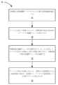
いくつかの実施形態では、流体制御デバイスを使用して、汚染が低減された体液試料を取得する方法は、流体収集デバイスを流体制御デバイスの出口に結合することを含む。流体収集デバイスの出口への結合は、流体制御デバイスの少なくとも一部分内に負圧差を生じさせるように構成されている。第1の流れコントローラは、負圧差が第1の大きさを有するときに、第1の状態から第2の状態に移行される。第1の流れコントローラは、第1の状態にあるときに、流体制御デバイスの隔離部分を出口から隔離し、第2の状態にあるときに隔離部分と出口との間に流体連通を確立するように構成されている。第1の流れコントローラが第2の状態にあるとき、初期体積の体液が、負圧差に応答して、流体制御デバイスの入口から隔離部へ受容される。第1の流れコントローラは、隔離部分が初期体積の体液を受容することに応答して、第2の状態から第3の状態に移行するように構成されている。第1の流れコントローラが第3の状態にあるとき、第1の流れコントローラは、出口から隔離部分を隔離し、負圧差は、第1の大きさから第2の大きさに増加する。第2の流れコントローラは、負圧差が第2の大きさを有するときに、第1の状態から第2の状態に移行される。第2の流れコントローラは、第1の状態にあるときに、流体制御デバイスのサンプリング部分を入口から隔離し、第2の状態にあるときに、サンプリング部分と入口との間に流体連通を確立するように構成されている。後続体積の体液は、サンプリング部分および出口を介して、入口から流体収集デバイスに移送される。 In some embodiments, a method of obtaining a reduced contamination body fluid sample using a fluid control device includes coupling a fluid collection device to an outlet of the fluid control device. The coupling to the outlet of the fluid collection device is configured to create a negative pressure differential within at least a portion of the fluid control device. The first flow controller is transitioned from the first state to the second state when the negative pressure difference has a first magnitude. The first flow controller is configured to isolate the isolation portion of the fluid control device from the outlet when in the first state and establish fluid communication between the isolation portion and the outlet when in the second state. It is composed of When the first flow controller is in the second state, an initial volume of body fluid is received from the inlet of the fluid control device into the isolation portion in response to the negative pressure differential. The first flow controller is configured to transition from the second state to the third state in response to the isolation portion receiving an initial volume of body fluid. When the first flow controller is in the third state, the first flow controller isolates the isolation portion from the outlet and the negative pressure differential increases from the first magnitude to the second magnitude. The second flow controller is transitioned from the first state to the second state when the negative pressure difference has a second magnitude. The second flow controller isolates the sampling portion of the fluid control device from the inlet when in the first state and establishes fluid communication between the sampling portion and the inlet when in the second state. It is configured as follows. A subsequent volume of body fluid is transferred from the inlet to the fluid collection device via the sampling portion and the outlet.
いくつかの実施形態では、流体制御デバイスは、入口および出口を含む。入口は、体液源または中間体液移送デバイスと流体連通して配置されるように構成されている。出口は、例えば、試料リザーバ(ボトル、容器、皿、バイアルなど)、培養ボトル、および真空コンテナ、液体収集デバイス、シリンジ、管腔含有デバイス、および/またはいずれかの他の適切な体液収集および/または移送デバイスなどの流体収集デバイスと流体連通して配置されるように構成されている。流体制御デバイスは、外部源(例えば、試料リザーバ、シリンジ、容器、および/またはいずれかの適切中間流体リザーバ)から生成された負圧差を流体制御デバイスに適用して、体液体液源から入口を通って、流体制御デバイスの隔離および/または分流部分(流体制御デバイスによって、またはその内部に形成され得る、またはそれに結合され得る)に、初期体積の体液を引き込む第1の状態を有する。流体制御デバイスは、(1)隔離および/または分流部分が初期体積を隔離し、(2)負圧差が体液源から、流体制御デバイスを通って、流体収集デバイス内に、実質的に汚染物質を含まない後続体積の体液を引き込む第2の状態を有する。 In some embodiments, the fluid control device includes an inlet and an outlet. The inlet is configured to be placed in fluid communication with a source of body fluid or an intermediate body fluid transfer device. Outlets can be connected to, for example, sample reservoirs (bottles, containers, dishes, vials, etc.), culture bottles, and vacuum containers, liquid collection devices, syringes, lumen-containing devices, and/or any other suitable body fluid collection and/or or configured to be placed in fluid communication with a fluid collection device, such as a transfer device. The fluid control device is configured to apply a negative pressure differential generated from an external source (e.g., a sample reservoir, a syringe, a container, and/or any suitable intermediate fluid reservoir) to the fluid control device to direct fluid flow from the source of body fluid through the inlet. has a first state of drawing an initial volume of body fluid into the isolation and/or diversion portion of the fluid control device (which may be formed by or within the fluid control device or coupled thereto). The fluid control device includes: (1) an isolation and/or diversion portion that isolates the initial volume; and (2) a negative pressure differential that substantially removes contaminants from the body fluid source, through the fluid control device, and into the fluid collection device. and a second state that draws in a subsequent volume of body fluid that does not contain the body fluid.
本明細書に記載の実施形態および/または方法のいずれも、例えば、血液試料などの、清潔なまたは実質的に混じりけのない体液試料の調達に使用することができる。いくつかの例では、体液試料(例えば、血液試料)は、細菌(例えば、グラム陽性細菌および/またはグラム陰性細菌)、真菌、酵母(例えば、カンジダ)、および/または他の望ましくない微生物のような、1つ以上の潜在的に望ましくない微生物の存在について検査することができる。診断検査中に、微生物、ならびに他の種類の生体物質、特定の種類の細胞、バイオマーカー、タンパク質、抗原、酵素、血液成分、および/または同様のものの存在を検出することを支援するために、様々な技術を採用することができる。例としては、分子ポリメラーゼ連鎖反応(PCR)、磁気共鳴および他の磁気分析プラットフォーム、自動顕微鏡、空間クローン単離、フローサイトメトリー、全血(「無培養」)検体分析(例えば、NGS)および関連技術、形態運動学的細胞分析、および/または患者検体を特徴付けるため、および/または特定の生物、抗生物質感受性、および/または同様のものを検出、識別、タイプ分け、分類、および/または特徴付けるために、他の一般的または発展的かつ高度な技術が含まれるが、これらに限定されるものではない。 Any of the embodiments and/or methods described herein can be used to procure a clean or substantially pure body fluid sample, such as, for example, a blood sample. In some instances, the body fluid sample (e.g., blood sample) contains bacteria such as bacteria (e.g., Gram-positive and/or Gram-negative bacteria), fungi, yeast (e.g., Candida), and/or other undesirable microorganisms. can be tested for the presence of one or more potentially undesirable microorganisms. To assist in detecting the presence of microorganisms, as well as other types of biological material, specific types of cells, biomarkers, proteins, antigens, enzymes, blood components, and/or the like during diagnostic tests; Various techniques can be employed. Examples include molecular polymerase chain reaction (PCR), magnetic resonance and other magnetic analysis platforms, automated microscopy, spatial clonal isolation, flow cytometry, whole blood (“culture-free”) specimen analysis (e.g., NGS) and related techniques, morphokinetic cell analysis, and/or to characterize patient specimens and/or to detect, identify, type, classify, and/or characterize specific organisms, antibiotic susceptibilities, and/or the like. including, but not limited to, other common or advanced advanced technologies.
例えば、いくつかの例では、微生物検査および/または検出は、培地(例えば、増殖を促進するための栄養豊富な培地および/または環境的に制御された培地、および/またはいずれかの数の他の培地)、一般的な添加物、および/または微生物増殖を助長する他の種類の溶液を含み得る、1つ以上の容器内で血液試料を培養することを含むことができる。血液試料中に存在する微生物および/または有機体のいずれかが、培地中で時間をかけて繁栄し、および/または増殖する(例えば、1時間未満から数日以上までの可変時間-これは、採用される診断技術に応じて、より長くまたはより短くなる可能性がある)。微生物および/または有機体の存在は、自動化された、連続的なモニタリング、および/または検出、識別、および/または同様のものに使用される分析プラットフォームおよび/または技術に特有の他の方法(例えば、二酸化炭素レベルの観察および/またはいずれかの他の適切な検出方法によって)によって検出することができる。 For example, in some instances, microbial testing and/or detection may be performed using a culture medium (e.g., a nutrient-rich medium to promote growth and/or an environmentally controlled medium, and/or any number of other culture medium), common additives, and/or other types of solutions that promote microbial growth. Any of the microorganisms and/or organisms present in the blood sample thrive and/or multiply in the culture medium over time (e.g., for a variable period of time from less than an hour to several days or more - this is (could be longer or shorter depending on the diagnostic technique employed). The presence of microorganisms and/or organisms can be determined by automated, continuous monitoring, and/or other methods specific to the analytical platform and/or technology used for detection, identification, and/or the like, e.g. , by observation of carbon dioxide levels and/or any other suitable detection method).
培地中の微生物および/または有機物の存在は、血液試料中の同じ微生物および/または有機物の存在を示唆しており、ひいては、試料が得られた患者の体液中の同じ微生物および/または有機物の存在を示唆している。他の例では、体液試料は、微生物および/または有機物の存在について指示されて(すなわち、培養されていない)分析され得る。従って、微生物および/または有機物が血液試料中に存在すると判定されると、患者は、診断され、患者から望ましくない微生物および/または有機物を治療するか、またはそうでなければ除去するために特別に考案された1つ以上の抗生物質または他の治療を処方されてもよい。 The presence of microorganisms and/or organisms in the culture medium suggests the presence of the same microorganisms and/or organisms in the blood sample, which in turn indicates the presence of the same microorganisms and/or organics in the body fluids of the patient from which the sample was obtained. It suggests. In other examples, body fluid samples may be analyzed directed (ie, uncultured) for the presence of microorganisms and/or organic matter. Accordingly, once microorganisms and/or organisms are determined to be present in a blood sample, the patient is diagnosed and given specific instructions to treat or otherwise remove the unwanted microorganisms and/or organisms from the patient. One or more antibiotics or other treatments may be prescribed.
しかしながら、患者試料は、調達中に汚染される、および/または偽陰性の結果を受ける可能性がある。例えば、検体調達プロセス中に(例えば、組織片、毛包、汗腺、および他の皮膚付属器構造物を介して直接または間接的に)取り除かれる体表からの微生物(例えば、皮膚に存在する微生物)は、その後、培養液、試験バイアル、または他の適切な検体収集または移送容器に患者検体と共に移送され得、および/またはそうでなければ分析されるべき検体に含まれ得る。可能性のある別の汚染源は、患者試料を引き出す人(例えば、医師、瀉血専門医、看護師、技術者など)および/または患者試料を引き出すために使用される機器からである。例えば、患者試料調達プロセス中に使用される機器、供給物、および/またはデバイスは、それぞれが潜在的な汚染ポイントを導入し得る複数の流体界面(例えば、患者から針、針から移送アダプタ、移送アダプタから試料容器、カテーテルハブからシリンジ、シリンジから移送アダプタ、針/管から試料容器、および/またはいずれかの他の流体界面、またはそれらのいずれかの組み合わせ)を含むことが多い。いくつかの例では、そのような汚染物質は、培地中で増殖する可能性があり、および/またはそうでなければ識別される可能性があり、それにより、患者内(すなわち、生体内)におけるそのような微生物の存在または欠如を不正確に反映する可能性のある、偽の、損なわれた、および/または誤った微生物検査結果のリスクまたは可能性が高くなる。 However, patient samples can become contaminated during procurement and/or receive false negative results. For example, microorganisms from body surfaces (e.g., microorganisms present on the skin) that are removed during the specimen procurement process (e.g., directly or indirectly via tissue debris, hair follicles, sweat glands, and other skin appendage structures). ) may then be transferred with the patient specimen to a culture medium, test vial, or other suitable specimen collection or transfer container, and/or otherwise included in the specimen to be analyzed. Another possible source of contamination is from the person drawing the patient sample (eg, doctor, phlebotomist, nurse, technician, etc.) and/or the equipment used to draw the patient sample. For example, equipment, supplies, and/or devices used during the patient sample procurement process may have multiple fluidic interfaces (e.g., patient-to-needle, needle-to-transfer adapter, transfer adapter to sample container, catheter hub to syringe, syringe to transfer adapter, needle/tubing to sample container, and/or any other fluid interface, or any combination thereof). In some instances, such contaminants may be able to grow in the culture medium and/or otherwise be identified, thereby preventing in-patient (i.e., in-vivo) There is an increased risk or likelihood of false, compromised, and/or erroneous microbial test results that may inaccurately reflect the presence or absence of such microorganisms.
汚染および/または他の不純物混入源によるこのような不正確な結果は、広範囲の疑わしい病気、疾患、感染症、患者の状態、および/または他の疾病を診断または治療しようとするときに懸念事項となる。例えば、微生物検査からの誤った結果は、患者の病気の誤診および/または治療の遅延をもたらす可能性がある(これは、患者への害および/または死亡をもたらす可能性があり、または一方で、患者が不必要に1つ以上の抗菌療法を受けることになり、これは、例えば、死亡を含む、患者への深刻な副作用および/または患者への結果を引き起こす可能性がある。このように、誤った結果は、患者の滞在期間の延長および/または誤った治療に関連するその他の合併症のために、医療システムに不必要な負担と費用を生じさせる。このような誤った結果に行きつく画像診断装置を使用することは、様々な画像診断法(例えば、CTスキャン)に関連する集中放射線への不必要な曝露が長期的な患者の健康に多くの既知の悪影響を及ぼすため、コストの観点と患者の安全性の観点の両方からも懸念される。 Such inaccurate results due to contamination and/or other sources of adulteration are a concern when attempting to diagnose or treat a wide range of suspected illnesses, illnesses, infections, patient conditions, and/or other illnesses. becomes. For example, an incorrect result from a microbiological test may result in a misdiagnosis of a patient's disease and/or a delay in treatment (which may result in harm and/or death to the patient, or , the patient will be unnecessarily subjected to one or more antimicrobial therapies, which may cause serious side effects and/or consequences for the patient, including, for example, death. , erroneous results create unnecessary burdens and costs on the healthcare system due to increased patient length of stay and/or other complications associated with incorrect treatment. The use of diagnostic imaging equipment is costly because unnecessary exposure to concentrated radiation associated with various imaging modalities (e.g., CT scans) has many known negative effects on long-term patient health. It is also of concern from both a clinical and patient safety perspective.
本明細書および/または本明細書に含まれる請求項のいずれかで使用されるように、単数形「a(一つの)」、「an(一つの)」および「the(その)」は、文脈が明らかにそうでないことを指示しない限り、複数の指示対象を含む。したがって、例えば、「部材」という用語は、単一の部材または部材の組み合わせを意味することを意図し、「材料」は、1つ以上の材料またはそれらの組み合わせを意味することを意図している。 As used in this specification and/or in any of the claims contained herein, the singular forms "a," "an," and "the" refer to Including multiple referents unless the context clearly dictates otherwise. Thus, for example, the term "member" is intended to mean a single member or a combination of members, and the term "material" is intended to mean one or more materials or a combination thereof. .
本明細書で使用されるように、記載された値および/または幾何学的構成または関係に関連して使用される場合、「約」、「およそ」、および/または「実質的に」という用語は、そのように定義された値または特性が、名目的に記載された値および/または記載された特性であることを伝えることを意図している。いくつかの例では、「約」、「およそ」、および/または「実質的に」という用語は、一般的に、望ましい許容範囲(例えば、記載された値または特性のプラスまたはマイナス10%)内で記載された値または特性を意味し、および/または想定することができる。例えば、約0.01の値は、0.009および0.011を含み得、約0.5の値は、0.45および0.55を含み得、約10の値は、9~11を含み得、約1000の値は、900~1100を含み得る。記載された値、構造、および/または関係は望ましいこともあり得るが、例えば、製造公差または他の実際的な考慮事項(例えば、デバイスの一部、導管、管腔などを介して印加される圧力または力など)の結果として、いくらかの変動が起こり得ることを理解されたい。したがって、「約」、「およそ」、および/または「実質的に」という用語は、本明細書では、そのような許容差および/または考慮事項を説明するために使用されることができる。 As used herein, the terms "about," "approximately," and/or "substantially" when used in connection with a stated value and/or geometric configuration or relationship. is intended to convey that the value or property so defined is a nominally stated value and/or property. In some instances, the terms "about," "approximately," and/or "substantially" generally mean within a desired tolerance (e.g., plus or minus 10% of the stated value or property). can mean and/or assume the values or characteristics described in . For example, a value of about 0.01 can include 0.009 and 0.011, a value of about 0.5 can include 0.45 and 0.55, and a value of about 10 can include 9-11. and values of about 1000 may include 900-1100. While the values, structures, and/or relationships described may be desirable, they may be subject to, e.g., manufacturing tolerances or other practical considerations (e.g., applied via part of the device, conduit, lumen, etc.). It is understood that some fluctuations may occur as a result of pressure or force, etc.). Accordingly, the terms "about," "approximately," and/or "substantially" may be used herein to describe such tolerances and/or considerations.
本明細書で使用されるように、「体液」は、患者の身体から直接的または間接的に取得された任意の流体を含むことができる。例えば、「体液」は、限定はされないが、血液、脳脊髄液、尿、胆汁、リンパ液、唾液、滑液、漿液、胸膜液、羊水、粘液、痰、硝子体液、空気など、またはそれらのいずれかの組み合わせを含む。 As used herein, "body fluid" can include any fluid obtained directly or indirectly from a patient's body. For example, "body fluid" may include, but is not limited to, blood, cerebrospinal fluid, urine, bile, lymph, saliva, synovial fluid, serous fluid, pleural fluid, amniotic fluid, mucus, sputum, vitreous humor, air, and/or the like. including combinations of the above.
本明細書で使用されるように、「近位」および「遠位」という用語は、デバイスを患者と接触させる位置に置くユーザに、それぞれ、近づく方向および遠ざかる方向を指す。したがって、例えば、患者の身体に最初に触れるデバイスの端は遠位端であり、デバイスの反対側の端(例えば、ユーザによって操作されているデバイスの端)は、デバイスの近位端である。 As used herein, the terms "proximal" and "distal" refer to directions toward and away from, respectively, a user who positions the device in contact with a patient. Thus, for example, the end of the device that first touches the patient's body is the distal end, and the opposite end of the device (eg, the end of the device being operated by the user) is the proximal end of the device.
本明細書で使用されるように、「プレ試料」、「第1の」、および/または「初期」という用語は、「試料」体積を調達する前に収集および/または隔離される体液の量、部分、または体積を記述するために互換的に使用することができる。「プレ試料」、「第1の」、および/または「初期」体積は、所定の、画定された、所望の、および/または所与の体液の体積を指すことができる。例えば、体液の所定および/または所望のプレ試料体積は、一滴の体液、数滴の体液、および/または約0.1ミリリットル(mL)、約0.2mL、約0.3mL、約0.4mL、約0.5mL、約1.0mL、約2.0mL、約3.0mL、約4.0mL、約5.0mL、約10.0mL、約20.0mL、約50.0mLに等しい体液の体積、および/またはそれらの間のいずれかの体積または端数に等しい体液の体積であり得る。あるいは、プレ試料体積は、50.0mLを超えても、または0.1mL未満であってもよい。いくつかの特定の実施形態では、所定のおよび/または所望のプレ試料体積は、約0.1mL~約5.0mLであることができる。他の実施形態では、プレ試料体積は、例えば、いずれかの数の管腔(例えば、体液源から初期収集チャンバ、部分、リザーバなどへの流路の少なくとも一部分を形成する管腔)の合計体積であり得る。 As used herein, the terms "pre-sample," "first," and/or "initial" refer to the amount of body fluid that is collected and/or isolated prior to procuring the "sample" volume. , part, or volume can be used interchangeably. A "pre-sample," "first," and/or "initial" volume can refer to a predetermined, defined, desired, and/or given volume of body fluid. For example, a given and/or desired pre-sample volume of body fluid may include a drop of body fluid, several drops of body fluid, and/or about 0.1 milliliter (mL), about 0.2 mL, about 0.3 mL, about 0.4 mL. , about 0.5 mL, about 1.0 mL, about 2.0 mL, about 3.0 mL, about 4.0 mL, about 5.0 mL, about 10.0 mL, about 20.0 mL, about 50.0 mL. , and/or any volume or fraction therebetween. Alternatively, the pre-sample volume may be greater than 50.0 mL or less than 0.1 mL. In some specific embodiments, the predetermined and/or desired pre-sample volume can be about 0.1 mL to about 5.0 mL. In other embodiments, the pre-sample volume is, for example, the total volume of any number of lumens (e.g., lumens forming at least a portion of the flow path from the body fluid source to the initial collection chamber, portion, reservoir, etc.) It can be.
本明細書で使用されるように、「試料」、「第2の」、および/または「後続」という用語は、例えば、1つ以上の試料または診断テストで使用される体液の体積、部分、または量を説明するために互換的に使用することができる。「試料」体積は、体液のプレ試料体積を収集、隔離、および/または単離した後に収集された体液のランダムな体積、あるいは所定または所望の体積であってもよい。体液の所望の試料体積は、例えば、約10.0mL~約60.0mLの間であり得る。あるいは、体液の所望の試料体積は、10.0mL未満または60.0mL超であってもよい。いくつかの実施形態では、例えば、試料体積は、少なくとも部分的に、試料体積に対して実行される1つ以上の検査、評価、分析、および/またはプロセスに基づくことができる。 As used herein, the terms "sample," "second," and/or "subsequent" refer to, for example, one or more samples or volumes, portions, or portions of body fluid used in a diagnostic test. or can be used interchangeably to describe a quantity. A "sample" volume may be a random volume of body fluid collected after collecting, isolating, and/or isolating a pre-sample volume of body fluid, or a predetermined or desired volume. The desired sample volume of body fluid can be, for example, between about 10.0 mL and about 60.0 mL. Alternatively, the desired sample volume of body fluid may be less than 10.0 mL or greater than 60.0 mL. In some embodiments, for example, the sample volume can be based, at least in part, on one or more tests, evaluations, analyzes and/or processes performed on the sample volume.
本明細書に記載の実施形態は、汚染が低減された、および/または実質的に汚染されていない体液を、1つ以上の流体収集デバイス(複数可)に移送するように構成することができる。いくつかの実施形態では、流体収集デバイスは、いずれかの適切な容器、コンテナ、リザーバ、ボトル、アダプタ、皿、バイアル、シリンジ、デバイス、診断および/または検査機械、および/または同様のものを含むことができるが、これらに限定されない。いくつかの実施形態では、流体収集デバイスは、例えば、Vacutainer(登録商標)(Becton Dickinson and Company(BD)製)、BacT/ALERT(登録商標)SNまたはBacT/ALERT(登録商標)FA(Biomerieux,Inc.製)、および/またはいずれかの適切なリザーバ、バイアル、マイクロバイアル、マイクロリットルバイアル、ナノリットルバイアル、コンテナ、マイクロコンテナ、ナノコンテナ、および/または同様のものなどの既知の試料コンテナと実質的に同様であるか、または同じであり得る。いくつかの実施形態では、流体収集デバイスは、2007年12月13日に出願された「Systems and Methods for Parenterally Procuring Bodily-Fluid Samples with Reduced Contamination」と題する米国特許第8,197,420号(「’420特許」)に記載されているもののうちのいずれかと同様であるか、および/または実質的に同じであってもよく、その開示は参照によりその全体が本明細書に組み込まれる。 Embodiments described herein can be configured to transfer reduced and/or substantially uncontaminated body fluids to one or more fluid collection device(s). . In some embodiments, the fluid collection device includes any suitable vessel, container, reservoir, bottle, adapter, dish, vial, syringe, device, diagnostic and/or testing machine, and/or the like. However, it is not limited to these. In some embodiments, the fluid collection device is, for example, Vacutainer® (Becton Dickinson and Company (BD)), BacT/ALERT® SN or BacT/ALERT® FA (Biomerieux, Inc.), and/or any suitable reservoir, vial, microvial, microliter vial, nanoliter vial, container, microcontainer, nanocontainer, and/or the like. may be similar or the same. In some embodiments, the fluid collection device is disclosed in a patent application entitled "Systems and Methods for Parenterally Procuring Bodily-Fluid Samples with Reduced Contamination," filed on December 13, 2007. No. 8,197,420 (`` may be similar and/or substantially the same as any of those described in the '420 Patent,'' the disclosure of which is incorporated herein by reference in its entirety.
いくつかの実施形態では、体液収集デバイスは、体液の試料体積を受容する前に、内容物を有していなくてもよい。例えば、いくつかの実施形態では、流体収集デバイスまたはリザーバは、例えば、真空ベースの収集管(例えば、Vacutaner(登録商標))、シリンジ、および/または同様のものなどの真空または吸引を画定または生成するように構成することができる。いくつかの実施形態では、試料リザーバは、例えば、いずれかの適切な添加剤、物質、酵素、油、流体、化合物、化学物質など(例えば、ヘパリン、クエン酸塩、酸性クエン酸塩デキストロース(ACD)、エチレンジアミン四酢酸(EDTA)、シュウ酸塩、ポリアネトールスルホン酸ナトリウム(SPS)、および/または同様のもの)を含むことができる。他の実施形態では、試料リザーバは、、例えば、好気性培地または嫌気性培地を含むことができる。試料リザーバ(例えば、培養ボトル)は、体液試料を受容することができ、これは、次いで、例えば、グラム陽性細菌、グラム陰性細菌、酵母、真菌、および/またはいずれかの他の有機体の存在について、(例えば、体外診断(IVD)検査および/またはいずれかの他の適切な検査を用いて培養した後に)検査され得る。培地の検査で陽性の結果が得られた場合、培地はその後、例えばPCRベースのシステムを使用して特定の有機物を識別するために検査することができる。 In some embodiments, the body fluid collection device may be empty of contents prior to receiving the sample volume of body fluid. For example, in some embodiments, the fluid collection device or reservoir defines or generates a vacuum or suction, such as, for example, a vacuum-based collection tube (e.g., Vacutaner®), syringe, and/or the like. It can be configured to: In some embodiments, the sample reservoir includes, for example, any suitable additives, substances, enzymes, oils, fluids, compounds, chemicals, etc. (e.g., heparin, citrate, acid citrate dextrose (ACD), etc.). ), ethylenediaminetetraacetic acid (EDTA), oxalate salts, sodium polyanetholesulfonate (SPS), and/or the like). In other embodiments, the sample reservoir can include, for example, an aerobic medium or an anaerobic medium. A sample reservoir (e.g., a culture bottle) can receive a body fluid sample, which in turn determines the presence of, e.g., Gram-positive bacteria, Gram-negative bacteria, yeast, fungi, and/or any other organisms. (eg, after culturing using an in vitro diagnostic (IVD) test and/or any other suitable test). If testing the medium yields a positive result, the medium can then be tested to identify specific organic matter using, for example, a PCR-based system.
「培地」という用語は、体液中の有機物(例えば、細菌などの微生物)と反応するように構成されている物質を説明するために使用されることができ、「添加物」という用語は、体液の一部分(例えば、血液の構成細胞、血清、滑液など)と反応するように構成されている物質を説明するために使用されることができ、試料リザーバは、いずれかの適切な物質、液体、固体、粉末、凍結乾燥化合物、気体などを含むことができることを理解すべきである。さらに、試料リザーバ内の「添加物」に言及する場合、添加物は、培地、添加物、および/またはいずれかの他の適切な物質、および/またはそれらのいずれかの組み合わせであり得ることが理解されるべきである。すなわち、本明細書に記載された実施形態は、いずれかの適切な物質を含むいずれかの適切な流体収集デバイス、リザーバ、および/または同様のものとともに使用され得る。 The term "medium" can be used to describe a substance that is configured to react with organic matter (e.g., microorganisms such as bacteria) in body fluids, and the term "additive" can be used to describe substances that are configured to react with organic matter (e.g., microorganisms such as bacteria) in body fluids. Can be used to describe a substance that is configured to react with a portion of blood (e.g., constituent cells of blood, serum, synovial fluid, etc.); sample reservoir is any suitable substance, liquid It should be understood that this can include solids, powders, lyophilized compounds, gases, and the like. Additionally, when referring to "additives" within the sample reservoir, the additives may be media, additives, and/or any other suitable substances, and/or any combination thereof. should be understood. That is, the embodiments described herein may be used with any suitable fluid collection device, reservoir, and/or the like containing any suitable material.
実施形態のいくつかは、1つ以上の培養試料検査のために体液を調達するために使用されるものとして本明細書で説明されているが、実施形態はそのような使用に限定されないことを理解されたい。本明細書に記載の実施形態および/または方法のいずれかは、体液の流れが、それと流体連通して配置された、任意の適切なデバイスに移送するように、使用されることができる。したがって、特定の実例が本明細書に記載されているが、デバイス、方法、および/または概念は、そのような特定の実例に限定されることを意図していない。 Although some of the embodiments are described herein as being used to procure bodily fluids for one or more culture sample tests, it is understood that the embodiments are not limited to such use. I want to be understood. Any of the embodiments and/or methods described herein can be used to transfer a flow of body fluid to any suitable device placed in fluid communication therewith. Thus, although particular examples are described herein, the devices, methods, and/or concepts are not intended to be limited to such particular examples.
本明細書に記載の実施形態および/またはその一部は、1つ以上の生体適合性材料で形成または構築されることができる。いくつかの実施形態では、生体適合性材料は、例えば、剛性、靭性、デュロメータ、生体反応性などの、構成材料の1つ以上の特性に基づいて選択されることができる。好適な生体適合性材料の例には、金属、ガラス、セラミック、またはポリマーが含まれる。好適な金属の実例は、医薬品グレードのステンレス鋼、金、チタン、ニッケル、鉄、プラチナ、スズ、クロム、銅、および/またはそれらの合金を含む。ポリマー材料は、生分解性または非生分解性であり得る。好適な生分解性ポリマーの実例は、ポリラクチド、ポリグリコリド、ポリラクチド-コ-グリコリド(PLGA)、ポリ無水物、ポリオルトエステル、ポリエーテルエステル、ポリカプロラクトン、ポリエステルアミド、ポリ(酪酸)、ポリ(吉草酸)、ポリウレタン、ならびに/またはそれらのブレンドおよびコポリマーを含む。非生分解性ポリマーの例には、ナイロン、ポリエステル、ポリカーボネート、ポリアクリレート、ポリシロキサン(シリコーン)、エチレンビニルアセテートおよび他のアシル置換セルロースアセテートのポリマー、非分解性ポリウレタン、ポリスチレン、ポリ塩化ビニル、ポリフッ化ビニル、ポリ(ビニルイミダゾール)、クロロスルホン酸ポリオレフィン、ポリエチレンオキサイド、および/またはそれらの混合および共重合体が含まれる。 Embodiments described herein and/or portions thereof can be formed or constructed of one or more biocompatible materials. In some embodiments, biocompatible materials can be selected based on one or more properties of the constituent materials, such as, for example, stiffness, toughness, durometer, bioreactivity, and the like. Examples of suitable biocompatible materials include metals, glasses, ceramics, or polymers. Examples of suitable metals include pharmaceutical grade stainless steel, gold, titanium, nickel, iron, platinum, tin, chromium, copper, and/or alloys thereof. Polymeric materials can be biodegradable or non-biodegradable. Examples of suitable biodegradable polymers are polylactide, polyglycolide, polylactide-co-glycolide (PLGA), polyanhydrides, polyorthoesters, polyetheresters, polycaprolactone, polyesteramides, poly(butyric acid), poly(butyric acid), grass acids), polyurethanes, and/or blends and copolymers thereof. Examples of non-biodegradable polymers include nylon, polyester, polycarbonate, polyacrylate, polysiloxane (silicone), polymers of ethylene vinyl acetate and other acyl-substituted cellulose acetates, non-degradable polyurethane, polystyrene, polyvinyl chloride, polyfluoride. vinyl chloride, poly(vinylimidazole), chlorosulfonic acid polyolefin, polyethylene oxide, and/or mixtures and copolymers thereof.
本明細書に記載された実施形態および/またはその部分は、1つ以上の部品、特徴、構造などから形成された構成要素を含むことができる。このような構成要素を参照する場合、構成要素は、いずれかの数のセクション、領域、部分、および/または特徴を有する単一部分によって形成され得るか、または複数の部分または特徴によって形成され得ることが理解されるべきである。例えば、壁またはチャンバなどの構造を指すときに、その構造は、複数の部分、または構造を形成するために結合された複数の別個の下部構造または同様のものを有する単一の構造と見なすことができる。したがって、モノリシックに構築された構造は、例えば、下部構造のセットを含むことができる。そのような下部構造のセットは、互いに連続的または不連続的のいずれかである、複数の部分を含み得る。一組の下部構造は、別々に製造され、後で(例えば、溶接、接着剤、スナップ、および/またはいずれかの適切な方法を介して)結合された、複数のアイテムまたは構成要素から作製されることもできる。 The embodiments described herein and/or portions thereof may include components formed from one or more parts, features, structures, etc. When referring to such a component, it is understood that the component may be formed by a single part having any number of sections, regions, portions, and/or features, or may be formed by multiple parts or features. should be understood. For example, when referring to a structure such as a wall or a chamber, the structure is considered to be a single structure having multiple parts, or multiple separate substructures or the like, combined to form the structure. I can do it. Thus, a monolithically constructed structure can include, for example, a set of substructures. Such a set of substructures may include multiple portions that are either continuous or discontinuous with each other. A set of substructures is made from multiple items or components that are manufactured separately and later joined (e.g., via welding, adhesives, snaps, and/or any suitable method). You can also
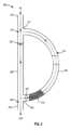
ここで図面を参照すると、図1は、実施形態による流体制御デバイス100の概略図である。概して、流体制御デバイス100(本明細書では「制御デバイス」または「デバイス」とも呼ばれる)は、患者から体液を引き出すように構成される。引き出された体液の第1の部分または量(例えば、初期量)は、引き出された体液の第2の部分または量(例えば、後続量)から隔離され、これは、その後、追加の検査のために使用され、廃棄され、および/または患者に再注入され得る。このようにして、汚染物質または同様のものは、第1の部分または量内で隔離されることができ、汚染物質を実質的に含まない第2の部分または量を残すことができる。次いで、体液の第2の部分または量は、本明細書でより詳細に記載されるように、医療診断および/または治療(例えば、血液培養検査または同様のもの)を目的とした1つ以上の検査で生体試料として使用されることができる。体液の第1の部分または量は、廃棄物として廃棄されるか、またはそこに含まれる潜在的な汚染物質の結果として、誤った、不正確な、歪んだ、一貫性のない、信頼できない結果を生成する可能性が低い任意の適切な検査で使用されることができる。状況によっては、例えば、血液などの体液の供給が制限されている患者では、体液の第1の部分または量を、いずれかの適切な方法を介して患者に再注入することができる。 Referring now to the drawings, FIG. 1 is a schematic illustration of a
制御デバイス100は、いずれかの適切な形状、サイズ、および/または構成であってもよい。例えば、いくつかの実施形態では、制御デバイス100は、例えば、制御デバイス100の隔離、分流、単離、および/または保存部分に少なくとも一時的に保存される体液の体積に少なくとも部分的に基づくサイズを有することができる。ここでさらに詳細に説明するように、制御デバイス100は、(1)体液の第1の部分または量が選択的に流体制御デバイスの少なくとも第1の部分を通って流れ、その後そこで隔離され、(2)体液の第2の部分または量が選択的に流体制御デバイスの少なくとも第2の部分を通って流れ、流体収集デバイスなどに流れ込むような動作モードの間で移行するように構成され得る。いくつかの実施形態では、制御デバイス100は、自動的に(例えば、圧力差、時間、電子信号または命令、膜または部材の飽和、吸収剤および/またはバリア材料などに基づいて)、または介入(例えば、ユーザ介入、機械的介入など)を介して、および/または応答して、動作モード間で移行するように構成され得る。
制御デバイス100は、入口112、少なくとも1つの出口116、および隔離チャンバ114を含む。さらに、制御デバイス100は、入口112と少なくとも隔離チャンバ114との間の1つ以上の流体流路113、および/または入口112と出口116との間の1つ以上の流体流路154を画定する。
制御デバイス100の入口112は、例えば、患者の脈管構造などの体液源と流体連通して配置されるように構成されている。いくつかの実施形態では、入口112は、例えば、静脈内(IV)カテーテル、針、末梢挿入中心静脈カテーテル(PICC)、シリンジ、1つ以上の滅菌管、および/またはいずれかの他の適切な管腔含有デバイスおよび/または中間移行デバイスのような入口デバイスに結合され、および/または含むことができる。いくつかの実施形態では、入口112は、ポート、バルブ、および/または、例えば、Luer Lok(登録商標)またはいずれかの他の適切なカプラーなどであり得る。そのような実施形態では、入口112(例えば、ポートまたはカプラー)は、患者(例えば、配置または留置されたIVカテーテルまたは針)と流体連通するアクセスまたは入口デバイスに結合するように構成され得る。いくつかの実施形態では、入口112は、ロック、カプラー、ポートなどを用いて、アクセスまたは入口デバイスに物理的および流体的に結合することができる。他の実施形態では、入口112は、例えば、滅菌管などのような中間管腔含有デバイスを介して、アクセスまたは入口デバイスと流体連通することができる。さらに他の実施形態では、制御デバイス100の入口112は、アクセスまたは入口デバイスを形成することができ、および/またはそれと一体的またはモノリシックに形成され得る。
隔離チャンバ114は、流体流路113を介して入口112と流体連通して少なくとも一時的に配置される。本明細書でさらに詳細に説明するように、隔離チャンバ114は、(1)入口112から体液の流れおよび/または体積を受容し、(2)その中で体液の流れおよび/または体積を隔離(例えば、分離、分別、封じ込め、保持、単離など)するように構成されている。
図1には示されていないが、いくつかの実施形態では、流体制御デバイス100は、そこを通って引き込まれる体液の流れを選択的に調節する1つ以上の流れ調節機能(例えば、流れリストリクタ、流体流れ抑制器など)を含む1つ以上の流路113(複数可)を有することができる。いくつかの実施形態では、流量調節機能は、構造的であり、流体制御デバイス100に組み込まれ得る。他の実施形態では、流れ調節機能は、別個に形成することができ、または本明細書でさらに詳細に説明するように、流体制御デバイス100内、例えば隔離チャンバ114内に導入することができる材料であり得る。 Although not shown in FIG. 1, in some embodiments,
制御チャンバ114は、いずれかの適切な形状、サイズ、および/または構成であってもよい。例えば、いくつかの実施形態では、隔離チャンバ114は、制御デバイス100(図1には図示せず)の本体部分によって少なくとも部分的に形成され得る。他の実施形態では、隔離チャンバ114は、制御デバイス100の一部分内に配置および/または配列されたリザーバであり得る。他の実施形態では、隔離チャンバ114は、流体流路113の一部分によって形成および/または画定され得る。すなわち、制御デバイス100は、1つ以上の管腔を画定することができ、および/または入口112から体液の流れを受容するように構成されている1つ以上の管腔画定デバイス(複数可)を含むことができ、それにより流体流路113が画定される。そのような実施形態では、管腔の少なくとも一部分、および/または管腔画定デバイス(複数可)の一部分は、隔離チャンバ114を形成、および/または画定することができる。
隔離チャンバ114は、いずれかの適切な体積および/または流体容量を有することができる。例えば、いくつかの実施形態では、隔離チャンバ114は、約0.25mL~約5.0mLの体積、および/または流体容量を有することができる。いくつかの実施形態では、隔離チャンバ114は、体液のマイクロリットル以下の体積(例えば、体液20滴、体液10滴、体液5滴、体液1滴、またはそれらの間のいずれかの適切な体積)で測定された体積を有することができる。他の実施形態では、隔離チャンバ114は、例えば、約5.0mL、10.0mL、15.0mL、20.0mL、30.0mL、40.0mL、50.0mL、またはそれ以上までの容積を有することができる。いくつかの実施形態では、隔離チャンバ114は、制御デバイス100に結合された、および/またはそれに含まれる入口デバイスの管腔、入口112の管腔、および入口112と隔離チャンバ114との間に画定された流体流路113の一部分、および/またはそれらのいずれかの組み合わせに等しい、および/またはそれに少なくとも部分的に基づく体積を有することができる。他の実施形態では、隔離チャンバ114は、入口デバイスの一部分、制御デバイス100の入口112、および入口112と隔離チャンバ114との間に画定された流体流路113の一部分の個々の、および/または組み合わせた体積に等しい、および/または少なくとも部分的に基づいた体積を有することができる。
図1には示されていないが、いくつかの実施形態では、流体制御デバイス100および/または隔離チャンバ114は、隔離チャンバ114内に移送された体液の一部分と相互作用するように構成された1つ以上の特徴または材料を含むことができ、および/またはこれらから形成することができる。例えば、いくつかの実施形態では、流体制御デバイス100および/または隔離チャンバ114は、バルブ、膜、ダイヤフラム、リストリクタ、ベント、選択的透過性部材(例えば、少なくとも選択的に空気またはガスの通過を可能にする流体不透過性のバリアまたはシール)、ポート、接合部、アクチュエータ、および/またはそのようなもの、またはそれらのいずれかの適切な組み合わせ(本明細書では「流れコントローラ」と総称される)を含むことができ、および/またはこれらを画定することができる。そのような流れコントローラは、隔離チャンバ114および/または流体制御デバイス100のいずれかの他の適切な部分に出入りする流体の流れを選択的に(少なくとも部分的に)制御するように構成することができる。これに関連して、流体の流れは、例えば、水、油、湿し流体、体液、および/またはいずれかの他の適切な液体のような液体であり得、および/または空気、酸素、二酸化炭素、ヘリウム、窒素、酸化エチレン、および/またはいずれかの他の適当な気体のような気体であり得る。 Although not shown in FIG. 1, in some embodiments, the
いくつかの実施形態では、1つ以上の開口部および/または1つ以上の流れコントローラは、隔離チャンバ114に出入りする空気の変位を容易にするように構成することができる。いくつかの実施形態では、初期部分の体液が隔離チャンバ114内に移送される際の隔離チャンバ114からの空気の変位は、隔離チャンバ114内の、および/または隔離チャンバ114と、例えば、流体源および/または隔離チャンバ114の外側の流体流路の一部との間の圧力、または隔離チャンバ114が通気される周囲環境の圧力の再配分を可能にする。いくつかの実施形態では、圧力の再分配は、制御デバイス100を介して体液がどのように流れるか、および/または隔離チャンバ114内に移行される体液の量または体積を判定および/または画定するための要因となり得る。 In some embodiments, one or more openings and/or one or more flow controllers can be configured to facilitate displacement of air into and out of
他の実施形態では、隔離チャンバ114および/または制御デバイス100は、いずれかの適切な方法で、流体流路113を通る体液の流れを選択的に制御するように動作可能な流れコントローラを含むことができる。例えば、いくつかの実施形態では、制御デバイス100は、制御デバイス100の2つ以上の部分の間の圧力差に少なくとも部分的に基づいて、ある体積の体液を隔離チャンバ114に、または出口116に選択的に移送するように構成することができる。いくつかの実施形態では、圧力差は、出口116を真空にした流体収集デバイス160(例えば、試料リザーバ、シリンジ、圧力チャージキャニスタ、および/または真空または圧力差を生成するための他のソースまたはポテンシャルエネルギー)に流体的に結合することから生じ得る。他の実施形態では、圧力差は、体積および/または温度の変化から生じ得る。さらに他の実施形態では、圧力差は、制御デバイス100の少なくとも一部分、および/または流路113および/または154の他の部分が真空になるおよび/または充填されること(例えば、隔離チャンバ114および/またはいずれかの他の適切な部分)から生じ得る。いくつかの実施形態では、圧力差は、自動的に、または直接または間接的な介入および/または操作(例えば、ユーザによる)を介して確立することができる。さらに、圧力差から生じる流体(例えば、気体および/または液体)の流れは、例えば、1つ以上の動作条件間で移行して流体の流れを制御することができる1つ以上の流れコントローラを介して、選択的に制御することができる。本明細書に記載の実施形態に含まれる流れコントローラは、限定ではなく例として提示されていることを理解されたい。したがって、特定の流れコントローラが本明細書で説明されているが、流体の流れは、いずれかの適切な手段によって制御デバイス100を通して制御できることを理解されたい。 In other embodiments,
いくつかの実施形態では、流体制御デバイス100の壁または構造は、隔離チャンバ114と流体連通している開口部、開口、ポート、オリフィスなどを画定することができる。いくつかの実施形態では、制御デバイス100は、開口部を通る流体(例えば、血液などの体液)の流れを制限または実質的に防止しながら、開口部を通る空気または気体の流れを選択的に許容するために、流体流路113での開口部内またはその周辺、または他の場所に配置された疎水性または親水性の膜のような半透性部材、膜、または材料を含むことができる。 In some embodiments, a wall or structure of
いくつかの実施形態では、例えば、制御デバイス100は、隔離チャンバ114内に配置された吸収性および/または親水性材料を含むことができる。したがって、体液が隔離チャンバ114内に移送されるとき、吸収性および/または親水性材料は、本明細書でさらに詳細に説明するように、体液の少なくとも一部分を吸収し、誘引し、保持し、膨張させ、および/または別の方法で体液の少なくとも一部分部と相互作用することができ、ひいては隔離チャンバ114内の体液の少なくとも初期部分を隔離し、および/または保持することができる。 In some embodiments, for example,
いくつかの実施形態では、流体制御デバイス100は、空気または空気圧(例えば、真空)の流れを許容するが、流体(例えば、液体)の流れを許容しない1つ以上の自己シール通気材料を含むことができる。例えば、濡れたとき、または流体と接触したときの自己シール材料は、吸収するか、さもなければ飽和し、自己シール材料が空気または液体を通過させないようにシール構成に移行することができる。自己シール材料(例えば、通気口)の移行は、流体制御デバイス100が第1の状態(例えば、体液の初期部分が隔離チャンバ114内に移送されている状態)から第2の状態(例えば、体液の初期部分が隔離チャンバ114内に移送された後)に移動することに関連していてもよい。 In some embodiments,
いくつかの実施形態では、隔離チャンバ114または流体制御デバイス100のいずれかの他の部分は、第1の状態(例えば、体液の初期部分が隔離チャンバ114に移送されている間)から第2の状態(例えば、体液の初期部分が隔離チャンバ114に移送された後)に移行するように構成されている膨張性または折り畳み式の材料を含むことができ、および/またはこれにより形成することができる。例えば、折り畳み式材料は、最初は、それが存在する流路113を遮断し、流体(例えば、気体または液体)の流れを許容しない溶解性物質の形態であり得る。しかしながら、所定量の流体と接触すると、材料は、材料は溶解するか、そうでなければ溶解構成に移行して、材料が配置されている流体流路113の閉塞を除去することができる。いくつかの実施形態では、そのような材料の膨張、折り畳み、溶解などに起因する構成の変化は、本明細書でさらに詳細に記載されるように、制御デバイス100および/または制御デバイス100のいずれかの適切な部分を、第1の状態、モード、位置、構成などから第2の状態、モード、位置、構成などに移行させるように動作可能であり得る。 In some embodiments,
いくつかの実施形態では、制御デバイス100および/または隔離チャンバ114は、例えば、ダックビルバルブ、バタフライバルブ、一方向逆止弁などのようなバルブを含むことができ、必要に応じて流体の流れを方向付けるために使用するいずれかの適切なクラッキング圧力(例えば、バルブを開くのに十分な圧力または力の量)を有するいずれかの適切な材料から作ることができる。例えば、流体制御デバイス100は、圧力の増加と共に順次開くように、クラッキング圧力が変化する2つ以上のバルブを含むことができる。このような構成は、例えば、流体の流れを方向付けるための適切な負圧源および適切な流れコントローラと組み合わせて使用することができる。 In some embodiments,
出口(複数可)116は、流体流路113および/または154と流体連通している、および/または流体連通して配置されるように構成されている。出口116は、いずれかの適切な出口、開口部、ポート、活栓、ロック、シール、カプラー、バルブ(例えば、一方向逆止弁、ダックビルバルブ、アンブレラバルブ、および/または同様のもの)などであり得、流体収集デバイス160に流体的に結合されるように構成されている。いくつかの実施形態では、出口116は、流体収集デバイス160、シリンジ、および/または他の中間体液移送デバイスとモノリシックに形成され得る。他の実施形態では、出口116は、接着剤、抵抗嵌合、機械的ファスナ、ねじ結合、穿孔または穿刺配置、いずれかの数の嵌め合い凹部、および/または他の適切な結合またはそれらの組み合わせを介して、収集デバイス160に少なくとも一時的に結合され得る。同様に述べると、出口116は、収集デバイス160によって画定された内部体積が、出口116と流体連通するように、収集デバイス160に物理的(例えば、機械的)および/または流体的に結合され得る。さらに他の実施形態では、出口116は、可撓性滅菌管などの、介在構造(図1には図示せず)を介して収集デバイス160に動作可能に結合され得る。さらに他の実施形態では、出口116は、流体の流れを収集デバイス160に適切に方向付ける下流の負圧源に、流体的に結合することができる。 Outlet(s) 116 are configured and/or arranged in fluid communication with
いくつかの実施形態では、出口116の配置は、収集デバイス160に結合する前に、出口116が物理的および/または流体的に密封されるようなものであり得る。いくつかの実施形態では、出口116は、収集デバイス160に結合されることに応答して、および/または出口116および/または制御デバイス100内の環境と、収集デバイス160内の環境との間の負圧差に応答して、密封構成から非密封構成に移行することができる。 In some embodiments, the arrangement of
流体収集デバイス160は、例えば、上記のものなどの体液を少なくとも一時的に含むためのいずれかの適切な装置であり得る。例えば、いくつかの実施形態では、流体収集デバイス160は、単回使用の使い捨て収集管、シリンジ、真空ベースの収集管、中間体液移送デバイス、および/または同様のものであり得る。いくつかの実施形態では、流体収集デバイス160は、例えば、Vacutainer(登録商標)、BacT/ALERT(登録商標)SNまたはBacT/ALERT(登録商標)FA、および/またはいずれかの他の適切なリザーバ、バイアル、マイクロバイアル、マイクロリットルバイアル、ナノリットルバイアル、コンテナ、マイクロコンテナ、ナノコンテナ、および/または同様のものなどの既知の試料コンテナと実質的に同様であるか、または同じであり得る。いくつかの実施形態では、収集デバイス160は、本明細書でさらに詳細に記載されているように、試料リザーバ内で負圧状態(真空状態)を維持する真空シールを含む試料リザーバであってもよく、ひいては、真空または吸引力を用いて、流体制御デバイス100を通して、患者から体液を試料リザーバ内に引き出すことを容易にすることができる。流体収集デバイス160が真空コンテナなどである実施形態では、ユーザは、収集デバイス160を出口116に結合させて、患者からの体液の流れを開始することができ、それによって、体液の第1または初期部分が隔離チャンバ114内に移送され、それにより隔離され、体液のいずれかの後続部分または体積が隔離チャンバ114を迂回し、および/またはそうでなければ隔離チャンバ114から分流して、流体収集デバイス160に流入する。
制御デバイス100の出口116は、流体収集デバイス160(例えば、試料リザーバ、シリンジなど)と流体的に結合され、かつ/またはそうでなければ流体連通して配置されるものとして上述したが、他の実施形態では、制御デバイス100は、いずれかの適切な体液収集デバイス、システム、および/または同様のものと組み合わせて使用することができる。例えば、いくつかの実施形態では、流体制御デバイス100は、2015年6月2日に出願された「Sterile Bodily-Fluid Collection Device and Methods」と題する米国特許公開第2015/0342510号(本明細書では「’510公報」と称する)に記載されているような、いずれかの適切な流体移送デバイスで使用することができ、その開示は、参照によりその全体が本明細書に組み込まれる。より具体的には、制御デバイス100は、「一体型」または事前に組み立てられたデバイス(例えば、´510公報に記載されているものなど)は、体液の最初の量を受け入れ、隔離して、その後の体液の量の汚染物質を低減および/または排除するように、使用されることができる。他の実施形態では、出口116は、アダプタ、出口針、および/または同様のものを含み得、および/またはそれらに結合され得る。例えば、いくつかの実施形態では、出口116は、例えば、2015年3月3日に出願された「 Apparatus and Methods for Disinfection of a Specimen Container」と題する米国特許公開第2015/0246352号(以下、「’352公報」と称する)に記載されている移送アダプタなど、移送アダプタおよび/または同様のものに結合され、および/またはそれらを含むことができ、その開示は、その全体が参照により本明細書に組み込まれる。 Although the
上述のように、デバイス100は、例えば、皮膚に存在する微生物、および/または同様のもののような、微生物からの汚染が低減された体液試料を調達するように、使用されることができる。例えば、いくつかの例では、医師、内科医、看護師、瀉血医、技術者などのユーザは、デバイス100を操作して、入口112と体液源(例えば、患者の静脈、脊髄腔からの脳脊髄液(CSF)、採尿、および/または同様のもの)との間に流体連通を確立することができる。特定の例として、いくつかの例では、入口112は、患者の皮膚を穿刺し、患者の静脈内に針の少なくとも一部分を挿入するように操作可能な針などに結合され、および/または含むことができ、それによって入口112を体液源(例えば、静脈、IVカテーテル、PICCなど)と流体連通して配置することができる。 As mentioned above,
いくつかの実施形態では、入口112が体液源(例えば、患者の一部分)と流体連通するように配置されると、出口116を、収集デバイス160に流体的に結合することができる。上記のように、収集デバイス160は、ある体積の体液を受容するように構成されているいずれかの適切なリザーバ、コンテナ、および/または収集システムであり得る。より具体的には、収集デバイス160は、例えば、負圧を画定する真空リザーバまたはコンテナであり得、および/または負圧を生成するように操作され得るシリンジであり得る。いくつかの例では、出口116を収集デバイス160に結合することにより、流体流路113および/または154の少なくとも一部分が選択的に負圧にさらされ、それにより、体液源(例えば、患者)から入口112を通って、流体制御デバイス100に体液を引き込む際に動作可能な負圧差が生じる。 In some embodiments,
いくつかの実施形態では、制御デバイス100の配置により、ある体積の体液が入口112におよび/またはそれを通って移送されるときに、体液の体積の初期部分(本明細書では「初期体積」または「第1の体積」とも呼ばれる)が入口112から、流体流路113の少なくとも一部分を通って、隔離チャンバ114に流入する。すなわち、いくつかの実施形態では、制御デバイス100は、体液の初期部分または体積が、流体流路113の少なくとも一部に、またはそれを通って、隔離部分114内へ流入することができるように第1または初期状態に置くことができる。例えば、いくつかの実施形態では、制御デバイス100の初期状態は、1つ以上の流れコントローラ(例えば、バルブ、膜、ダイヤフラム、リストリクタ、通気口、空気透過性および流体不透過性バリア、ポート、および/または同様のもの)が、流体流路113が隔離チャンバ114を介して負圧差にさらされる第1の状態にある状態であり得る。言い換えれば、試料リザーバ160内の負圧(またはシリンジまたは他の負圧源によって生成された)は、1つ以上の流れコントローラが第1のまたは初期状態にあるときに、体液の初期の流れを隔離チャンバ114内に引き込む際に動作可能な隔離チャンバ114の少なくとも一部分内に負圧(または負圧差)をもたらすことができる。 In some embodiments, the arrangement of
例えば、いくつかの実施形態では、制御デバイス100は、流体収集デバイス160と隔離チャンバ114との間の流路に少なくとも一時的に流体的に結合される、上記のような1つ以上の流れコントローラ(複数可)を含むことができる。いくつかの実施形態では、流れコントローラは、流体収集デバイス160と入口112との間の流路に少なくとも一時的に流体的に結合することができる。いくつかの実施形態では、上記の流れコントローラの例は、例えば、流体および空気の流れを制御するために医療デバイスで使用される既知の市販の構成要素であり得るが、他の実施形態では、流れコントローラは、デバイス100に統合されたカスタム、独自、および/または特別に調整されたコンポーネントであり得る。流れコントローラが第1のまたは初期状態にあるとき、流れコントローラは、収集デバイス160の負圧に応答して、流体の流れがそれを通過することを許容することができる。いくつかの実施形態では、流れコントローラは、空気または気体の流れのみが流れコントローラを通ることを許容するように構成され、流れコントローラを通る液体(例えば、体液)の流れを制限および/または実質的に阻止するように構成されている。このように、収集デバイス160は、流れコントローラが第1のまたは初期状態にあるときに、体液の初期部分が流体流路154に流入し、および/または隔離チャンバ114から流出することを許容することなく、体液の初期部分および/または量を隔離チャンバ114内に引き込むように動作可能な負圧差を生成することができる。 For example, in some embodiments,
図1には示されていないが、いくつかの実施形態では、制御デバイス100は、隔離チャンバ114がさらされる、負圧の大きさを調節するように構成されている部材、デバイス、機構、特徴などを含むことができる。例えば、いくつかの実施形態では、制御装置100は、バルブ、膜、多孔質材料、リストリクタ、および/または圧力を調節するように構成されたいずれかの他の適切な部材および/またはデバイスを含むことができる。いくつかの実施形態では、隔離チャンバ114がさらされ得る圧力の大きさを調整および/または制御することで、ひいては体液に、および/または患者の静脈内に与えられる圧力の大きさを調節することができる。いくつかの例では、そのような圧力調整は、例えば、血液試料の溶血および/または静脈をつぶす可能性を低減することができる(例えば、これは、制御デバイス100の使用に関連する微生物および/または他の診断検査を必要とする脆弱な患者において特に重要である)。加えて、負圧の調整により、例えば、制御デバイス100が第1の構成または状態と第2の構成または状態との間で移行する速度を、少なくとも部分的に制御することができる。いくつかの実施形態では、負圧を調整することは、タイマーのように機能することができる。例えば、負圧差の導入と、第1の状態から第2の状態へのダイバータの移行との間の時間は、既知であってもよく、予め定められていてもよく、計算されていてもよく、および/または制御されてもよい。このように、いくつかの例では、負圧を調節することで、少なくとも部分的に、隔離チャンバ114内に移送される体液の量または体積を制御することができる(例えば、体液の初期量の体積を制御することができる)。 Although not shown in FIG. 1, in some embodiments,
体液の初期部分および/または量は、上述のように、体液の任意の適切な体積であることができる。例えば、いくつかの例では、制御デバイス100は、体液の所定のおよび/または所望の体積(例えば、初期体積)が隔離チャンバ134に移送されるまで、第1の状態に留まることができる。いくつかの実施形態では、初期体積は、隔離チャンバ114の体積に関連付けられ、および/または少なくとも部分的にそれに基づくことができる。初期量は、制御デバイス100の1つ以上の部分が第1の動作状態またはモードから第2の動作状態またはそれ以上に移行する前に、デバイス内に移送され得る体液の量または体積に関連付けられ、および/または少なくとも部分的に基づくことができる(例えば吸収性、膨張性、親水性、および/または浸潤性材料によって吸収され得る体液の量、通気材料または半透水性部材または膜を完全に湿らせるかまたは飽和させるのに十分な体液の量、制御デバイス100内の1つ以上の圧力差を等しくするのに十分な量、バルブまたはアクチュエータを移行させるのに十分な量、および/または同様のもの)。 The initial portion and/or amount of body fluid can be any suitable volume of body fluid, as described above. For example, in some examples,
初期体積の体液が隔離チャンバ114に移送および/または分流された後、初期体積は、隔離チャンバ114内で隔離、分別、保持、収容、単離などされる。例えば、いくつかの実施形態では、1つ以上の流れコントローラの第1の状態から第2の状態への移行は、隔離チャンバ114内で体液の初期部分を隔離および/または保持するように動作可能であり得る。本明細書でさらに詳細に記載されるように、いくつかの例では、例えば、静脈穿刺イベント中に除去された皮膚に存在する微生物などの汚染物質、他の外部汚染源、試料を収集するために使用されるカテーテルおよびPICCラインのコロニー形成、および/または同様のものなどの汚染物質は、初期体積の体液に混入および/または含まれ、したがって、初期体積が隔離チャンバ114内で隔離されるときに、そこで隔離される。 After the initial volume of body fluid is transferred and/or diverted to the
初期体積が隔離チャンバ114に移送および/または分流されると、デバイス100は、後続体積(複数可)の体液が流体流路113および/または154を通って、入口112から出口116へ流れることができる、第2の状態に移行することができる。いくつかの実施形態では、制御デバイス100は、体液の初期体積が隔離チャンバ114に隔離されると、受動的および/または自動的に(例えば、ユーザ介入なしで)第1の状態から第2の状態に移行することができる。例えば、いくつかの実施形態では、隔離チャンバ114を容量まで充填し、および/または完全に飽和させ、湿潤させ、および/または隔離チャンバ114と試料リザーバ160との間に配置された吸収剤または同様の材料を含浸させることにより、隔離チャンバ114への体液のさらなる移動が、負圧の除去または転換のために制限され、および/または実質的に防止されることが可能になる。他の実施形態では、制御デバイス100は、手動で移行、またはユーザによる少なくとも間接的な相互作用に応答して移行することができる。例えば、いくつかの実施形態では、ユーザは、開口部および/または通気口を少なくとも部分的に閉塞することができる。他の実施形態では、ユーザは、アクチュエータなど(図1には図示せず)を作動させて、制御デバイス100を第1の状態から第2の状態に移行させることができる。さらに他の実施形態では、初期体積の体液の少なくとも一部分は、制御デバイス100を第1の状態から第2の状態に移行させることができる。例えば、制御デバイス100は、体液活性化スイッチ、バルブ、ポート、および/または同様のものを含むことができる。他の実施形態では、ある体積の体液は、例えば、ポート、流路、および/または出口を開くことができる1つ以上のアクチュエータなどを移動および/または変位させることができる。さらに他の実施形態では、ユーザは、そのようなスイッチ、バルブ、ポート、アクチュエータなどを操作して、制御デバイス100を第1の状態から第2の状態に移行させることができる。 Once the initial volume is transferred and/or diverted to
収集デバイス160が出口116に流体的に結合され、制御デバイス100が第2の状態にある場合(例えば、初期体積の体液が隔離チャンバ134内にまたは隔離チャンバ134によって隔離される)、いずれかの後続体積(複数可)の体液は、入口112から、流体流路113および/または154の少なくとも1つを通って、出口116を通って、収集デバイス160に流入することができる。したがって、上述のように、1つ以上の試料体積の体液を収集または調達する前に、隔離チャンバ114内で初期体積の体液を隔離することにより、1つ以上の試料体積中の汚染物質の量が減少および/または実質的に排除される。さらに、いくつかの実施形態では、制御デバイス100の配置により、隔離チャンバ114内で初期体積を収集および隔離する前に、制御デバイス100は第2の状態に移行することができない。 When
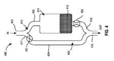
図2は、一実施形態による流体制御デバイス200の断面側面図を示している。流体制御デバイス200は、少なくとも形態および/または機能において、図1を参照して上記で説明した流体制御デバイス100と同様であり得る。したがって、流体制御デバイス100の部分と同様であり得る流体制御デバイス200の部分は、本明細書ではさらに詳述されることはない。 FIG. 2 shows a cross-sectional side view of a
図2に示されるように、流体制御デバイス200(本明細書では「制御デバイス」または「デバイス」とも呼ばれる)は、入口212、出口216、および隔離チャンバ210を含む。制御デバイス100を参照して上述したように、入口212は、そこからの体液の流れを受容するために(例えば、針、IVカテーテル、PICCラインなどの管腔含有デバイスを介して)、体液源と流体連通して配置されるように構成されている。出口216は、例えば、’510公報に記載されているものと同様の移送デバイスなど、流体収集デバイス、シリンジ、および/または他の中間体液移送デバイスまたは容器(図2には図示せず)に流体的に結合されるように構成されている。 As shown in FIG. 2, fluid control device 200 (also referred to herein as a “control device” or “device”) includes an
流体制御デバイス100を参照して上述したように、制御デバイス200は、入口212と隔離チャンバ212との間の1つ以上の流体流路213、および/または入口212と出口216との間の1つ以上の流体流路254を含む。制御デバイス200は、いずれかの適切な形状、サイズ、および/または構成を有し得る。例えば、いくつかの実施形態では、デバイス200は、少なくとも形状および/または機能において、図1を参照して上記で説明したデバイス100と実質的に同様であり得る。いくつかの実施形態では、デバイス200は、第1の部分224および第2の部分225を含むことができる。図2に示されるように、いくつかの実施形態では、第2の部分225は、例えば、第1の部分224と物理的に結合され、かつ選択的に流体連通するバイパスおよび/または分流部分であり得る。さらに、デバイス200は、第2の部分225の第1の端部(例えば、入口端)が第1の部分224に結合される位置において第1の接合部217を含み、および/または形成し、第2の部分225の第2の端部(例えば、出口端)が第1の部分224に結合される位置において第2の接合部218を含み、および/または形成する。すなわち、デバイス200は、例えば、第2の接合部218で再結合される第1の接合部217において分岐部(例えば、第2の部分225)を有する、および/または形成するように構成することができる。いくつかの実施形態では、第2の部分225は、D字形の構成および/または配置を形成、および/または有することができる。他の実施形態では、第1の部分224および/または第2の部分225は、いずれかの適切な構成および/または配置(例えば、蛇行構成、ループ構成、らせん構成、いずれかの適切な幾何学的構成、および/または同様のもの)を形成、および/または有することができる。いくつかの実施形態では、デバイス200の第1の部分224および/または第2の部分225は、いずれかの適切な形状および/またはサイズを有し、いずれかの適切な構成および/または配置に置かれるように再構成可能または移動可能である可撓性チューブなどを含むことができ、および/またはこれによって形成することができる。 As described above with reference to
いくつかの実施形態では、デバイス200の隔離チャンバ214は、デバイス200の第2の部分225によって形成され、および/またはそれに含まれ得る。(例えば、第1の接合部217における)第2の部分225の第1の部分224への結合により、流体流路213および第1の接合部217を介して、隔離チャンバ214を入口212と流体連通して選択的に配置することができる。同様に、(例えば、第2の接合部218における)第2の部分225の第1の部分224への結合により、流体流路254および第2の接合部218を介して、隔離チャンバ214を、出口216、および/または流体流路254および第2の接合部218を介して出口216に結合された流体収集デバイスと流体連通して選択的に配置することができる。 In some embodiments,
本明細書でさらに詳細に説明するように、隔離チャンバ214は、(1)入口212から体液の流れおよび/または体積を選択的に受容し、(2)その中で体液の流れおよび/または体積を隔離(例えば、分離、分別、封じ込め、保持、単離など)するように構成されている。隔離チャンバ214は、いずれかの適切な形状、サイズ、および/または構成であってもよい。例えば、いくつかの実施形態では、隔離チャンバ214は、例えば、隔離チャンバ114に関して上記で説明されたものなど、いずれかの適切なサイズ、体積、および/または流体容量を有することができる。いくつかの実施形態では、流体流路213の少なくとも一部分は、デバイス200の一部分および/または第1の接合部217を通って延在して、隔離チャンバ214の少なくとも一部分を形成および/または画定することができる。他の実施形態では、第1の接合部217および/または隔離チャンバ214は、流体流路213を隔離チャンバ214から少なくとも一時的に分離することができる流れ制御機構および/または同様のものを含むことができる。いくつかの実施形態では、デバイス200は、流れコントローラ221、222、および/または215などの1つ以上の流れコントローラを含み、形成し、および/または画定することができる。流れコントローラ221、222、および/または215は、例えば、1つ以上の所望の位置に配置され、隔離チャンバ214および/またはデバイス200の他の適切な部分への流体の流入/流出を選択的に(少なくとも部分的に)制御するように構成されているバルブ、膜、ダイヤフラム、リストリクタ、通気口、選択的透過性部材(例えば、Porex(登録商標)のような血液関門、および/または同様のものなど、気体または空気を少なくとも選択的に通過させる流体不透過性バリアまたはシール)、ポートなど(本明細書では総称して「流れコントローラ」と呼ばれる)であってもよい。 As described in further detail herein, isolation chamber 214 (1) selectively receives a flow and/or volume of body fluid from
より具体的には、図2に示される実施形態では、流れコントローラ221および222はそれぞれ、特定の、所望の、および/または所定のクラッキング圧力などを有するように構成されたバルブであり得る。バルブ221および/または222は、例えば、パイプまたはチューブシステムに沿ったいずれかの位置に好適に配置されるように構成され得る、インラインまたはライニングパイプインサート(LP)バルブであり得る。いくつかの実施形態では、バルブ221および/または222は、クラッキング圧力を超える特定の量の圧力がバルブ221および/または222に印加されて、バルブ221および/または222をそれぞれ閉状態から開状態に移行させるまで、空気または液体の流れを制限または実質的に防止して、閉状態に留まるように構成することができる。 More specifically, in the embodiment shown in FIG. 2, flow
いくつかの実施形態では、バルブ221および/または222および他の追加のバルブ(図示せず)はそれぞれ、可変のクラッキング圧力を有し、デバイス200内および/またはそれに沿っていずれかの適切な位置に配置されるように構成することができる。例えば、いくつかの実施形態では、図2に示されるように、バルブ221は、デバイス200の第1の部分224内、および第1の接合部217の下流に配置され得、バルブ222は、デバイス200の第2の部分225内、および第2の接合218の上流および/またはその前に配置され得る。いくつかの実施形態では、デバイス200は、バルブ221がバルブ222よりも大きなクラッキング圧力を有するように構成することができ、それによって、適用された真空源を使用してバルブ221および222を連続的に開くことができる。例えば、各バルブ221、222のクラッキング圧力、および負圧源によって与えられる圧力は、隔離チャンバ214に向かっての、かつ/またはその中への体液の連続的および/またはそうでなければ所望の第1の流れを達成し、次いで出口216および流体収集デバイスに向かっての体液の所望の第2の流れを達成するように集合的に構成することができる。 In some embodiments,
具体例によって、いくつかの実施形態では、負圧源(例えば、流体収集デバイスおよび/または同様のもの)は、およそ8ポンド/平方インチ(psi)の大きさを有する真空を画定することができる。したがって、負圧源が出口216に結合されると、圧力はバルブ221および222の両方に伝達される。いくつかの実施形態では、バルブ221は、例えば、3.4psiのクラッキング圧力を有し得、バルブ222は、例えば、0.017psiのクラッキング圧力を有し得る。このように、負圧源を出口216に結合した結果として生じる負圧差は、ひいては、(より高いクラッキング圧力を有する)バルブ221を実質的に閉じた構成または状態から実質的に開いた構成または状態に移行させる前に、(より低いクラッキング圧力を有する)バルブ222を実質的に閉じた構成または状態から実質的に開いた構成または状態に移行させることができる。いくつかの例では、バルブのこの連続的な開放(すなわち、バルブ221の前のバルブ222)は、以下にさらに記載されるように、流体の流れ(例えば、第1の流れ)を隔離チャンバ214に方向付け、次いで、流体の流れ(例えば、第2の流れ)を、流体収集デバイスおよび/または出口216に結合された負圧源に方向付けるように動作可能であり得る。 By way of example, in some embodiments, the negative pressure source (e.g., fluid collection device and/or the like) can define a vacuum having a magnitude of approximately 8 pounds per square inch (psi). . Thus, when a negative pressure source is coupled to
デバイス200は、いくつかの実施形態では、空気に対して選択的に透過性であるが、流体(例えば、液体)に対して不透過性または少なくとも選択的に透過性である材料の形態の1つ以上の流れコントローラを含むことができる。例えば、デバイス200は、空気の流れを可能にするか、または負圧源からの真空を伝達するが、体液(例えば、疎水性)の流れを可能または伝達しない材料で作られた1つ以上の膜を含むことができる。いくつかの実施形態では、デバイス200は、体液またはいずれかの他の適切な作動形態と相互作用する前に、第1のまたは初期状態または構成にあり得、次いで、体液またはいずれかの他の適切な作動形態と相互作用する際に第2の状態または構成に移行し、および/または移行されることが可能な流れコントローラを含むことができる。例えば、いくつかの実施形態では、そのような流れコントローラは、それを通る体液の流れを実質的に制限および/または防止しながら、それを通る空気の流れを選択的に可能に初期または第1の状態にあり得る。体液(またはいずれかの他の適切な流体)と相互作用すると、流れコントローラは、第2の状態に移行することができ、この状態で、流れコントローラは、それを通る空気の流れおよび体液の流れに対して実質的に不浸透性であり得る。
図2に示される実施形態に示されるように、デバイス200は、膜、多孔質材料、吸収性材料などの形態の流れコントローラ215を含むことができる。流れコントローラ215は、任意の適切な形状、サイズ、および/または構成であってよい。いくつかの実施形態では、流れコントローラ215は、例えば、それを通る液体の流れを制限および/または実質的に防止しながら、それを通る空気の流れを可能にするいずれかの適切な孔径を有する多孔質材料から形成することができる。例えば、いくつかの実施形態では、流れコントローラ215は、直径が約17mmであり、孔径が約0.45マイクロメートル(μm)である膜などであり得る。他の実施形態では、流れコントローラ215は、いずれかの適切な直径(例えば、1mm、2mm、3mm、4mm、5mm、10mm、15mm、20mm、30mm、またはそれ以上、および/またはそれらの間のいずれかの直径)を有する膜および/または同様のものであり得る。同様に、他の実施形態では、流れコントローラ215は、いずれかの適切な孔径を有する膜および/または同様のものであり得る。いくつかの実施形態では、流れコントローラ、膜、および/または同様のものの孔径は、例えば、引き出され、収集され、および/または隔離される流体の種類(例えば、体液)、流体の流れ(例えば、体液の流れおよび/または空気の流れ)において予想される粒子状物質の量または種類、使用される真空源、および/または予想される負圧差の大きさ、および/またはいずれかの他の適切な要因または考慮事項に基づくことができる。 As shown in the embodiment shown in FIG. 2,
図示されるように、流れコントローラ215は、デバイス200内に配置されて、接合部218を介した、第2の部分225および/または隔離チャンバ214と出口216との間で、流体連通を選択的に確立する。したがって、流れコントローラ215が半透過性部材として構成されていることにより、本明細書でさらに詳細に記載されるように、流れコントローラ215は、デバイス200の第2の部分225および/または隔離チャンバ214から、流れコントローラ215および接合部218を通って、流体流路254に気体または空気が移送されることを少なくとも一時的に許容するように構成することができ、(例えば、接合部218を介して)、第2の部分225および/または隔離チャンバと流体流路254との間の液体(例えば、体液)の流れを制限および/または実質的に防止するように構成され得る。図示されていないが、いくつかの実施形態では、デバイス200は、流れコントローラ215の状態を制御および/または移行するように構成されている1つ以上のアクチュエータなどを含むことができる。デバイス200の出口216は、流体流路213および/または254と流体連通している、および/または流体連通して配置されるように構成されている。出口216は、いずれかの適切な出口、開口部、ポート、ロック、シール、カプラーなどであり得、試料リザーバ、シリンジ、コンテナ、および/または他の試料容器などの流体収集デバイスに流体的に結合されるように構成されている。いくつかの実施形態では、出口216は、流体収集デバイスとモノリシックに形成することができ、またはデバイス100の出口116を参照して上述したように、流体収集デバイスに少なくとも一時的に結合されることができる。流体収集デバイスは、例えば、収集デバイス160に関して上記で詳細に説明されたもののいずれかなど、体液を収容するためのいずれかの適切な収集システムであり得る。より具体的には、いくつかの実施形態では、出口216は、真空の試料リザーバに結合するように構成することができる。いくつかの他の実施形態では、出口216は、流体収集デバイスにも結合されている一方で、出口216の下流の負圧源に結合するように構成することができる。このように、ユーザは、流体収集デバイスを出口216に結合させて、患者からの体液の流れを開始することができ、それによって、体液の第1のまたは初期部分が隔離チャンバ214内に移送され、それにより隔離され、体液のいずれかの後続部分または体積が隔離チャンバ214を迂回し、および/またはそうでなければ隔離チャンバ214から分流して、流体収集デバイスに流入する。 As shown, a
上述のように、デバイス200は、例えば、皮膚に存在する微生物、および/または同様のもののような、微生物からの汚染が低減された体液試料を調達するように、使用されることができる。例えば、いくつかの例では、医師、内科医、看護師、瀉血医、技術者などのユーザは、デバイス200を操作して、入口212と体液源(例えば、患者の静脈)との間に流体連通を確立することができる。入口212が体液源(例えば、患者の一部分)と流体連通するように配置されると、出口216を、流体収集デバイスに流体的に結合することができる。上記のように、図2に示される実施形態では、流体収集デバイスは、負圧源であり得、および/または負圧差を生成するように構成され得る。例えば、流体収集デバイスは、負圧を画定する真空リザーバまたはコンテナ、シリンジ、ポンプ、および/またはいずれかの他の負圧源であり得る。他の実施形態では、流体収集デバイスは、別個の負圧源に結合されるように構成されているコンテナ、リザーバ、またはデバイスであり得る。 As mentioned above,
出口216を流体収集デバイスおよび/または負圧源に結合することにより、流体流路254の少なくとも一部分が、流体収集デバイス内またはそれを通過する負圧に選択的にさらされる。上記のように、流れコントローラ215および/またはバルブ221および222は、デバイス200を通る流体の流れを選択的に制御するように構成することができる。より具体的には、出口216を流体収集デバイスおよび/または負圧源に結合すると、流体流路254内に負圧差をもたらし、ひいては、バルブ221および222が負圧にさらされる。上記のように、いくつかの実施形態では、バルブ221は、バルブ222のクラッキング圧力(例えば、0.017psi)と比較して、より大きなクラッキング圧力(例えば、3.4psi)を有することができる。さらに、バルブ222の上流の流れコントローラ215は、初期または第1の状態の膜であり得、流れコントローラ215は、空気または気体の流れに対して透過性である。いくつかの例では、そのような配置により、バルブ222が閉状態から開状態に移行をもたらし、それによって、負圧がバルブ222および流れコントローラ215を通って隔離チャンバ214に伝達される。 By
したがって、体液源(例えば、患者)から、入口212を通って、流体流路213に体液を引き込む際に動作可能な負圧差が生成される。さらに、バルブ222が開状態にあり、バルブ221が閉状態にある場合、体液は、流体流路213を通って、隔離チャンバ214に(例えば、接合部217を介して)流入することができる。制御デバイス100を参照して上述したように、制御デバイス200の配置により、ある体積の体液が入口212におよび/またはそれを通って移送されるときに、体液の体積の初期部分(本明細書では「初期体積」または「第1の体積」とも呼ばれる)が入口212から、流体流路213の少なくとも一部分および/または接合部217を通って、隔離チャンバ214に流入する。すなわち、いくつかの実施形態では、制御デバイス200は、体液の初期部分または体積が、流体流路213の少なくとも一部および/または接合部217に、またはそれを通って、隔離部分214内へ流入することができるように、第1または初期状態に置くことができる。デバイス200が第1の状態または初期状態にあるとき、バルブ221は閉状態にあり、したがって、体液は、バルブ221を通過せず、流体流路254にも実質的に入らない。 Thus, a negative pressure differential is created that is operable in drawing body fluid from a body fluid source (eg, a patient) through
上記のように、制御デバイス200は、流れコントローラ222(バルブ)が開状態にあるときに初期状態にあり得、ひいては負圧差によって、初期量の体液を隔離チャンバ214に引き込むことが許容される。いくつかの例では、体液は、流れが流れコントローラ215(例えば、上記のように、選択的透過性膜または部材)に到達するまで、第2の部分225(例えば、隔離チャンバ214)を通って流れることができる。膜215は、その初期状態または第1の状態にあり得、したがって、空気に対して透過性であるが、液体に対しては不透過性であり得る。このように、膜215は、流体流路213と隔離チャンバ214との間の直接的な液体連通を単離、分離、分別、隔離、および/またはそうでなければ防止する。さらに、入口212は、隔離チャンバ214を介して負圧差にさらされる。言い換えれば、流体収集デバイス内の負圧は、制御デバイス200が第1のまたは初期状態にあるときに、入口212から、流体流路213の少なくとも一部および/または接合部217を通って、隔離チャンバ214内に体液の初期流れを引き込む際に動作可能なデバイス200の少なくとも第2の部分225(例えば、隔離チャンバ214)内に負圧(または負圧差)を生じさせることができる。 As mentioned above, the
流れコントローラ215が第1のまたは初期状態にあるとき、流れコントローラ215は、デバイス100を参照して上述したように、試料リザーバ(またはシリンジまたは負圧を生成するために使用される他のポテンシャルエネルギー源)の負圧に応答して、流体(例えば、気体または空気)の流れを通過させることができる。流れコントローラ215(例えば、選択的透過性膜または部材)は、隔離チャンバ214への初期量の体液の流れに応答して、空気に対して透過性であり液体に対して不透過性である第1の状態から、空気に対して不透過性であり液体に対して不透過性である第2の状態に移行するように構成することができる。例えば、隔離チャンバ214を最大に充填することは、体液を飽和させ、湿潤させ、および/または流れコントローラ215(例えば、膜材料)を含浸させることに対応し、および/またはそうでなければそれらをもたらすことができ、流れコントローラ215を第1の状態から第2の状態に移行させることができる。第2の状態では、流れコントローラ215は、空気および液体に対して不浸透性であり、それにより、隔離チャンバ214と負圧源(例えば、流体収集デバイス)との間の流体連通を制限および/または実質的に防止する。言い換えれば、隔離チャンバ214は、隔離チャンバ214を満たす初期体積の体液に応答して、負圧源から隔離することができる。 When the
体液の初期部分および/または量は、制御デバイス100を参照して詳述したように、体液のいずれかの適切な体積であり得る。例えば、いくつかの例では、初期体積は、流れコントローラ215(例えば、選択的透過性膜または部材)を完全に湿潤または飽和させるのに十分な体液の量または体積に関連付けられ、および/または少なくとも部分的に基づくことができる。言い換えれば、いくつかの実施形態では、体液の初期体積は、流れコントローラ215を第2の状態(例えば、飽和または完全湿潤状態)に移行させるのに十分な体積であり得る。いくつかの実施形態では、流れコントローラ215は、第2の状態に移行するときに密封構成に配置される。すなわち、流れコントローラ215(例えば、半透性材料)を飽和および/または完全に湿潤させることにより、流れコントローラ215は、流れコントローラ215がそれを通る液体および気体の流れを実質的に防止する密封構成に配置される。 The initial portion and/or amount of body fluid may be any suitable volume of body fluid, as detailed with reference to control
初期体積の体液が隔離チャンバ214に移送および/または分流された後、制御デバイス200は、その第2の状態または動作モードに移行して、隔離チャンバ214内で初期体積を隔離、分別、保持、封じ込め、単離などすることができる。例えば、上記のように、流れコントローラ215は、密封構成に配置され、これは、隔離チャンバ214を流体流路254から流体的に隔離する。さらに、流れコントローラ215の移行は、隔離チャンバ214を満たす初期量の体液に応答することができる。したがって、隔離チャンバ214内の初期量の体液は、さらなる量の体液が隔離チャンバ214に移送されることを制限および/または実質的に防止することができる。したがって、体液の初期量および/または一部分は、隔離チャンバ214内に隔離および/または保持される。上記のように、いくつかの例では、例えば、静脈穿刺イベント中に除去された皮膚に存在する微生物などの汚染物質は、初期体積の体液に混入および/または含まれ、したがって、初期体積の体液が隔離チャンバ214内で隔離されるときに、そこで隔離される。 After the initial volume of body fluid has been transferred and/or diverted to the
流れコントローラ215が第2の状態(例えば、不浸透性または密封状態)にある場合、本来なら隔離チャンバ214上に、または隔離チャンバ214を介して与えられる負圧は、流体流路254上に、または流体流路254を介して与えられるようになり、したがって、流れコントローラ221に与えられる。いくつかの例では、負圧の大きさは、負圧が流れコントローラ221をその第1の状態からその第2の状態に移行させるのに十分になるまで、流体流路254内で構築および/または増大することができる。より具体的には、流れコントローラ221がバルブである場合、バルブ221のクラッキング圧力に打ち勝つのに十分になるまで負圧を増大させることができる。このように、バルブがその開状態にあるとき(および/または流れコントローラ221がそうでなければ第2の状態にあるとき)、入口212は、流体流路213を介して負圧差にさらされる。流体収集デバイスが出口216に流体的に結合され、制御デバイス200が第2の状態にある場合(例えば、初期体積の体液が隔離チャンバ214内にまたはそれによって隔離される)、いずれかの後続体積(複数可)の体液は、入口212から、流体流路213および254を通って、流れコントローラ221(例えば、バルブ)を通って、出口216を通って、流体収集デバイスに流入することができる。したがって、上述のように、1つ以上の試料体積の体液を収集または調達する前に、隔離チャンバ214内で初期体積の体液を隔離することにより、1つ以上の試料体積中の汚染物質の量が減少および/または実質的に排除される。さらに、いくつかの実施形態では、制御デバイス200の配置により、隔離チャンバ214内で初期体積を収集および隔離する前に、制御デバイス200は第2の状態に移行することができない。 When the
図2には示されていないが、いくつかの実施形態では、制御デバイス200は、第1の状態と第2の状態との間で(例えば、ユーザによって印加される力を介して)移動するように構成されているアクチュエータおよび/または同様のものを含むことができる。他の実施形態では、制御デバイスは、2つ以上の流体流路(例えば、流体流路213および254)間で流体連通を選択的に確立するように構成されているいずれかの適切な部材、デバイス、機構などを含むことができる。 Although not shown in FIG. 2, in some embodiments,
いくつかの例では、隔離チャンバ214がさらされる負圧差の大きさを調整および/または制御することが望ましい場合がある。図2には示されていないが、デバイス200は、負圧差の大きさを低減および/または制御するための1つ以上の手段を含むことができる。例えば、いくつかの実施形態では、デバイス200は、流体流路213および/または254よりも小さい直径を有する制限流路経路(複数可)または流路の一部分を含むことができる。例えば、いくつかの実施形態では、1つ以上の制限流路は、約1.0マイクロメートル(μm)、約10.0μm、約100.0μm、約1000.0μm、約10,000.0μm、約100,000.0μm、および/またはそれらの間でいずれかの適切な直径を有することができる。他の実施形態では、制限流路は、1.0μm未満か、または100,000.0μm超の直径を有することができる。そのような実施形態では、制限流路がより小さな直径を有することにより、制限流路がより大きな直径を有する場合の負圧の大きさよりも、隔離チャンバ214を介して印加される負圧の大きさが小さくなることがある。さらに、いくつかのそのような実施形態では、1つ以上の制限流路は、例えば、液体(例えば、体液)の流れではなく、気体または空気の流れを受容するように構成されている気体流路であり得る。いくつかの実施形態では、制限流路の直径は、それを通る液体の流れを制限および/または防止するのに十分に小さくすることができる。 In some examples, it may be desirable to adjust and/or control the amount of negative pressure differential to which
いくつかの実施形態では、制限流路は、例えば、接合部218と流れコントローラ215との間に配置され得、それによって、体液および/または他の液体の流れは、流れコントローラ215(例えば、選択的透過性バリアまたはシール)によって実質的に防止される。より具体的には、いくつかの実施形態では、制限流路は、例えば、流れコントローラ222(例えば、バルブ)と流れコントローラ215(例えば、選択的透過性膜または部材)との間に配置することができる。したがって、流れコントローラ222は、流れコントローラ215がさらされる負圧を超える大きさの負圧にさらされる可能性がある。そのような実施形態では、より大きな負圧により、流れコントローラ222のその第1の状態からその第2の状態への移行が容易になり得る。例えば、いくつかの実施形態では、流れコントローラ222がバルブである場合、この配置は、バルブのクラッキング圧力に打ち勝つのに十分な負圧差にバルブをさらすことを許容できる。 In some embodiments, a restricted flow path may be disposed, e.g., between
圧力変調は、制限流路の直径に基づくものとして上で説明されているが、これは、限定ではなく例としてのみ提示されていることを理解されたい。例えば、いくつかの実施形態では、制御デバイスは、いずれかの適切な数の制限流路を含むことができ、そのそれぞれは、実質的に同じ直径を有することができ、または異なる直径を有することができる。例えば、いくつかの実施形態では、制御デバイスは、最大100以上の制限流路を含むことができる。そのような実施形態では、制限流路のそれぞれは、約1.0μm~約100.0μmの間、約1.0μm~約10.0μmの間、または約1.0μm~約5.0μmの間の直径を有することができる。いくつかの実施形態では、複数の制限流路は、(1)隔離チャンバ214を負圧差にさらす出口216と隔離チャンバ214との間の流路を選択的に提供し、(2)液体(例えば、体液)の通過を実質的に防止しながら、気体および/または空気の通過を選択的に許容するように構成されている流れコントローラとして機能するように構成され得る。隔離チャンバがさらされる負圧の大きさを調節する他の手段は、例えば、多孔質材料、バルブ、膜、ダイヤフラム、特定の制限、通気口、変形可能な部材または流路、および/またはいずれかの他の適切な手段を含むことができる。いくつかの実施形態では、流れコントローラ215は、所望の量の負圧調節を提供するために、所定のおよび/または所望の多孔性を有する選択的透過性膜または部材であり得る。 Although pressure modulation is described above as being based on the diameter of the restriction channel, it should be understood that this is offered by way of example only and not limitation. For example, in some embodiments, the control device can include any suitable number of restriction channels, each of which can have substantially the same diameter or can have different diameters. I can do it. For example, in some embodiments, the control device can include up to 100 or more restricted flow paths. In such embodiments, each of the restriction channels is between about 1.0 μm and about 100.0 μm, between about 1.0 μm and about 10.0 μm, or between about 1.0 μm and about 5.0 μm. can have a diameter of In some embodiments, the plurality of restricted flow paths (1) selectively provide a flow path between the
いくつかの実施形態では、隔離チャンバ214がさらされ得る圧力の大きさを調整および/または制御することで、ひいては体液に、および/または患者の静脈内に与えられる圧力の大きさを調節することができる。いくつかの例では、そのような圧力調整は、例えば、血液試料の溶血および/または静脈が崩壊する可能性を減少させることができる。いくつかの例では、負圧の量または大きさを調節および/または制御する能力により、制御デバイス200を、生理学的課題を有し得る広範囲の患者にわたって使用することを可能にし得、それにより、例えば血液などの体液の収集を容易にするために負圧がしばしば必要とされる(例えば、大気圧と患者の血管圧との間の圧力差は、一貫した十分に強力な流れを促進にするのに十分ではない可能性がある)が、急激な力が平坦化し、急減し、落ち込み、および/またはそうでなければ血液を収集するための開存性および能力を阻害するほどの圧力ではない。 In some embodiments, adjusting and/or controlling the amount of pressure to which the
図3は、別の実施形態による流体制御デバイス300を示している。流体制御デバイス300(本明細書では「制御デバイス」または「デバイス」とも呼ばれる)は、いずれかの適切な形状、サイズ、および/または構成であり得る。例えば、いくつかの実施形態では、流体制御デバイス300は、図1を参照して上述した流体制御デバイス100および/または図2を参照して上述した流体制御デバイス200と、少なくとも形態および/または機能において同様であり得る。したがって、流体制御デバイス100および/または200の部分と同様であり得る流体制御デバイス300の部分は、本明細書ではさらに詳述されることはない。 FIG. 3 shows a
図2に示される流体制御デバイス200を参照して上述したように、図3に示される流体制御デバイス300は、入口312、出口316、および隔離チャンバ314を含む。入口312は、そこからの体液の流れを受容するために(例えば、針、IVカテーテル、PICCラインなどの管腔含有デバイスを介して)、体液源と流体連通して配置されるように構成されている。出口316は、例えば、’510公報に記載されているものと同様の移送デバイスなど、流体収集デバイス、シリンジ、真空コンテナ、および/または他の中間体液移送デバイスまたは容器(図3には図示せず)に流体的に結合されるように構成されている。さらに、制御デバイス300は、入口312と隔離チャンバ314との間の1つ以上の流体流路313、および/または入口312と出口316との間の1つ以上の流体流路354を含み、および/または画定する。 As described above with reference to
いくつかの実施形態では、デバイス300は、第1の部分324および第2の部分325を含むことができる。図3に示されるように、いくつかの実施形態では、第2の部分325は、例えば、第1の部分324と物理的に結合され、かつ選択的に流体連通するバイパスおよび/または分流部分であり得る。さらに、デバイス300は、第2の部分325の第1の端部(例えば、入口端)が第1の部分324に結合される位置において第1の接合部317を含み、および/または形成し、第2の部分325の第2の端部(例えば、出口端)が第1の部分324に結合される位置において第2の接合部318を含み、および/または形成する。すなわち、デバイス300は、例えば、第2の接合部318で再結合される第1の接合部317において分岐部(例えば、第2の部分325)を有する、および/または形成するように構成することができる。いくつかの実施形態では、デバイス300の第1の部分324および/または第2の部分325は、いずれかの適切な形状および/またはサイズを有し、いずれかの適切な構成および/または配置に置かれるように再構成可能または移動可能である可撓性チューブなどを含むことができ、および/または形成することができる。 In some embodiments,
本明細書でさらに詳細に説明するように、隔離チャンバ314は、(1)入口312から体液の流れおよび/または体積を受容し、(2)その中で体液の流れおよび/または体積を隔離(例えば、分離、分別、封じ込め、保持、単離など)するように構成されている。隔離チャンバ314は、いずれかの適切な形状、サイズ、および/または構成を有し得る。例えば、いくつかの実施形態では、隔離チャンバ314は、例えば、隔離チャンバ114および/または214に関して上記で説明されたものなど、いずれかの適切なサイズ、体積、および/または流体容量を有することができる。いくつかの実施形態では、流体流路313の少なくとも一部分は、デバイス300の一部分を通って延在して、隔離チャンバ314の少なくとも一部分を形成および/または画定することができる。いくつかの実施形態では、デバイス300の隔離チャンバ314は、形態および/または機能において、1つ以上の隔離チャンバ114および/または214と実質的に同様であってもよい。したがって、隔離チャンバ314の一部分は、本明細書ではさらに詳述されない場合がある。 As described in further detail herein, the isolation chamber 314 (1) receives a flow and/or volume of body fluid from the
図3に示されるように、隔離チャンバ314は、デバイス300の第2の部分325によって形成および/またはそれに含まれ得、(1)流体流路313および第1の接合部317を介した入口312と、(2)流体流路354および第2の接合部318を介した出口316と、流体連通して選択的に配置され得る。このように、隔離チャンバ314は、(1)入口312から体液の流れおよび/または体積を選択的に受容し、(2)その中で体液の流れおよび/または体積を隔離(例えば、分離、分別、封じ込め、保持、単離など)するように構成されている。 As shown in FIG. 3,
いくつかの実施形態では、流体制御デバイス300は、1つ以上の流れコントローラを含み、および/または画定することができる。流れコントローラは、例えば、適切に配置され、隔離チャンバ314および/またはデバイス300のいずれかの他の適切な部分への流体の流入/流出を選択的に(少なくとも部分的に)制御するように構成されているバルブ、膜、ダイヤフラム、リストリクタ、通気口、選択的透過性部材(例えば、Porex(登録商標)のような血液関門、および/または同様のものなど、気体または空気を少なくとも選択的に通過させる流体不透過性バリアまたはシール)、ポートなど(本明細書では総称して「流れコントローラ」と呼ばれる)を含むことができる。デバイス300のいくつかの実施形態では、図3に示すように、選択的透過性部材315、逆止弁322、および溶解性の部材323のような流れコントローラを含むことができ、これらは、機能の特定の状態の下および/または特定の条件の下で、1つ以上の特定の方向への流体の流れを可能にし、方向付け、制御し、および/または妨げるように配置されている。 In some embodiments,
図3に示されるように、デバイス300の第2の部分325は、逆止弁322および選択的透過性部材315を含むことができる。例えば、いくつかの実施形態では、逆止弁322および/または選択的透過性部材315は、隔離チャンバ314の近位または第2の端部の上に、そこに、またはその近くに配置することができる。言い換えれば、逆止弁322および選択的透過性部材315は、出口または隔離チャンバ314の出口部分において、その上に、またはその近くに配置することができる。別の言い方をすれば、逆止弁322および/または選択的透過性部材は、第1の接合部317よりも第2の接合部318に近い隔離チャンバ314の端部において、その上に、またはその近くに配置することができる。いくつかの実施形態では、逆止弁322および/または選択的透過性部材315は、第2の接合部318の少なくとも一部分に統合することができる。いくつかの実施形態では、逆止弁322は、デバイス200を参照して上記で説明したバルブ222と実質的に同様であり得る。例えば、いくつかの実施形態では、逆止弁322は、バルブ222を参照して上記で説明したような所望のクラッキング圧力を有するように構成することができる。したがって、逆止弁322は、デバイス200を参照して上述したように、例えば、流体流路354と隔離チャンバ314との間の流体の流れを選択的に制御するように構成することができる。このように、逆止弁322は、本明細書ではさらに詳細に説明されていない。さらに、いくつかの実施形態では、デバイス300は、逆止弁および/またはいずれかの他の適切なバルブを含む必要はない。 As shown in FIG. 3, the
選択的透過性部材は、いずれかの適切な形状、サイズ、および/または構成であってもよい。例えば、いくつかの実施形態では、選択的透過性部材315は、例えば、膜、多孔質材料、吸収性材料、親水性または疎水性材料、選択的透過性バリアなどであり得る。いくつかの実施形態では、選択的透過性部材315は、流れコントローラ215(例えば、選択的透過性部材および/または膜)と実質的に同様であってもよく、したがって、選択的透過性部材315の態様は、本明細書においてさらに詳細に説明されることはない。選択的透過性部材315は、デバイス300の第2の部分325および/または隔離チャンバ314から、選択的透過性部材315および接合部318を通って、流体流路354に気体または空気が移送されることを少なくとも一時的に可能にするように構成することができ、(例えば、接合部318を介して)、第2の部分325および/または隔離チャンバと流体流路354との間の液体(例えば、体液)の流れを制限および/または実質的に防止するように構成され得る。いくつかの実施形態では、選択的透過性部材315は、第1のまたは初期状態にあり得、デバイス300がその第1の状態および/または構成にあるとき、選択的透過性部材315は、空気または気体の流れがそれを通って移送されることを可能にする。本明細書にさらに詳細に記載されているように、選択的透過性部材315は、デバイス300がその第2の状態および/または構成にあるときに、選択的透過性部材315がすべての流体(気体および/または液体)に対して実質的に不透過性である第2の状態または構成に移行することができ、および/またはそうでなければ、その第2の状態または構成にあることができる。 The selectively permeable member may be of any suitable shape, size, and/or configuration. For example, in some embodiments, selectively
いくつかの実施形態では、溶解性部材323は、デバイス300の第1の部分内の適切な位置に配置することができる。例えば、いくつかの実施形態では、溶解性部材323は、図3に示されるように、第1の接合部317に、および/またはその近くに配置することができる。いくつかの実施形態では、溶解性部材323は、接合部317および/または接合部317の少なくとも一部分に統合することができる。このように、溶解性部材323は、例えば、選択的透過性部材315の上流にあり得る。 In some embodiments,
本明細書でさらに詳細に説明するように、溶解性部材323は、例えば体液などの流体との接触に応答して、第1のまたは初期状態から第2の状態に移行するように構成することができる。いくつかの実施形態では、例えば、溶解性部材323は、第1の接合部317内および/またはその近くに配置して、デバイス300が第1のまたは初期状態にあるときに、入口312を流体流路354から分離することができる。初期体積の体液を隔離チャンバ314に移送することに応答して、および/またはその後、デバイス300は、第1のまたは初期状態から第2の状態に移行することができる。いくつかの実施形態では、デバイス300が第2の状態にあるとき、溶解性部材323は実質的に溶解することができ、ひいては入口312と流体流路354との間に流体連通を確立することができる。いくつかの例では、例えば、初期体積の体液が隔離チャンバ314に流入するときに、体液の一部分は溶解性部材323に接触することができる。本明細書でさらに詳細に説明されるように、体液との接触により、ひいては溶解性部材323の溶解が開始され得、それにより、デバイス300がその第2の状態および/または構成にされると、溶解性部材323が少なくとも実質的に溶解し、それによって入口312は流体流路354と流体連通して配置される。 As described in further detail herein,
上述のように、デバイス300は、例えば、皮膚に存在する微生物、および/または同様のもののような、微生物からの汚染が低減された体液試料を調達するように、使用されることができる。例えば、いくつかの例では、医師、内科医、看護師、瀉血医、技術者などのユーザは、デバイス300を操作して、入口312と体液源(例えば、患者の静脈)との間に流体連通を確立することができる。入口312が体液源(例えば、患者の一部分)と流体連通するように配置されると、出口316を、流体収集デバイスに流体的に結合することができる。上記のように、図3に示される実施形態では、流体収集デバイスは、例えば、真空リザーバ、シリンジ、および/または負圧を画定するいずれかのコンテナであるか、または負圧の下流源に結合され得る。 As mentioned above,
出口316を流体収集デバイスに結合することにより、流体流路354の少なくとも一部分が、流体収集デバイス内の負圧に選択的にさらされる。その第1のまたは初期状態にあるときのデバイス300の配置は、その第1の状態または構成にある1つ以上の流れコントローラを含む。例えば、選択的透過性部材315、逆止弁322、および溶解性部材323は、それぞれ、出口316が流体収集デバイスに結合されているとき、その第1の状態および/または構成にあり得る。負圧に応答して、逆止弁322は、実質的閉状態(例えば、その第1の構成または状態)から実質的開状態(例えば、その第2の構成および/または状態)に移行するように構成することができる。例えば、いくつかの例では、出口316と流体収集デバイスとの間に流体連通を確立することにより、逆止弁322を、例えば、逆止弁322のクラッキング圧力を超える負圧差にさらすことができる。したがって、逆止弁322は、その第2の状態および/または構成に置くことができる。他の実施形態では、デバイス300は、逆止弁および/または他の適切なバルブを含む必要はない。そのような実施形態では、逆止弁322を移行させるように本来ならば動作可能な負圧差は、代わりに、選択的透過性部材315に与えられ、これは、逆止弁322が第2の状態または開状態にある場合と実質的に同様である。 By
上記のように、選択的透過性部材315および溶解性部材323は、出口316が流体収集デバイスに結合されるとき、それぞれ、その第1の状態または構成にある。このように、選択的透過性部材315は、流れコントローラ215を参照して上述したように、それを通る液体の流れを遮断および/または防止しながら、空気、気体、および/または負圧の流れを可能にするように構成することができる。さらに、溶解性部材323がその第1の状態または構成にある場合、溶解性部材323は、例えば、入口312と流体流路354との間の流体連通を遮断、分離、および/または妨害するように構成することができ、それによって、そこを通る流体(空気または液体または負圧)の流れを可能にすることはない。したがって、出口316を流体収集デバイスに結合することにより、隔離チャンバ314が流体収集デバイスの負圧にさらされ、それにより、体液源(例えば、患者)から入口312を通って、隔離チャンバ314に体液を引き出す際に動作可能な負圧差が生じる。 As described above, selectively
制御デバイス100および200を参照して上述したように、制御デバイス300の配置により、ある体積の体液が入口312におよび/またはそれを通って移送されるときに、体液の体積の初期部分(本明細書では「初期体積」または「第1の体積」とも呼ばれる)が入口312から、および隔離チャンバ314に流入する。すなわち、いくつかの実施形態では、デバイス300は、体液の初期部分または体積が、流体収集デバイスに関連する負圧差に応答して、入口312から隔離チャンバ314に流入することができる、その第1または初期状態にある。言い換えれば、流体収集デバイス内の負圧は、制御デバイス300が第1のまたは初期状態にあるときに、入口312から、隔離チャンバ314内に体液の初期流れを引き込む際に動作可能な隔離チャンバ314の少なくとも一部分内に、負圧(または負圧差)を生じさせることができる。上で詳細に説明したように、いくつかの例では、本明細書で説明したようないずれかの適切な手段によって、負圧差の大きさを調整および/または制御することが望ましい場合がある。 As described above with reference to control
体液の初期部分および/または量は、制御デバイス100および/または200を参照して詳述したように、体液のいずれかの適切な体積であり得る。例えば、いくつかの例では、初期体積は、膜315を完全に湿潤または飽和させるのに十分な体液の量または体積に関連付けられ、および/または少なくとも部分的に基づくことができる。言い換えれば、いくつかの実施形態では、体液の初期体積は、選択的透過性部材315を第2の状態(例えば、飽和または完全湿潤状態)に移行させるのに十分な体積であり得る。流れコントローラ215を参照して上述したように、選択的透過性部材315は、第2の状態に移行されると、密封構成に置かれる。したがって、選択的透過性部材315を第2の状態に移行させることにより、選択的透過性部材315を通る流れは、隔離、遮断、単離、分離、分別離、および/またはさもなければ防止される。 The initial portion and/or amount of body fluid may be any suitable volume of body fluid, as detailed with reference to control
初期体積の体液が隔離チャンバ314に移送および/または分流された後、制御デバイス300は、その第2の状態または動作モードに移行して、隔離チャンバ314内で初期体積を隔離、分別、保持、封じ込め、単離などすることができる。上記のように、選択的透過性部材315は、密封構成に配置され、したがって、それを通る流体の流れを実質的に防止する。この実施形態では、制御デバイス300の配置により、選択的透過性部材315が密封構成に配置されたときに、選択的透過性部材315を介して本来与えられる負圧の少なくとも一部分が、代わりに流体流路354上および/またはその中に与えられる。しかしながら、負圧は、溶解性部材323がその第1の状態および/または構成からその第2の状態および/または構成に移行するまで(例えば、少なくとも部分的に溶解するまで)、流体流路354内で隔離され得る。 After the initial volume of body fluid has been transferred and/or diverted to the
選択的透過性部材315がその第2の状態で密封され、隔離チャンバ314が引き出された初期体積の体液によって容量まで充填されると、接合部317でおよび/またはその近くに少なくとも一時的に保持される体液の量により、溶解性部材323をその第1の状態からその第2の状態に移行させるのに十分な量の体液を溶解性部材323と接触させることができる。言い換えれば、隔離チャンバ314をファイリングすることにより、十分な体積または量の体液を溶解性部材323と接触させて、溶解性部材323を実質的に溶解させ、それによって、それをその第2の状態または構成に移行させることができる。溶解可能な部材323の移行は、ひいては流体制御デバイス300をその第1の状態からその第2の状態に移行させるのに十分である。 Once the selectively
溶解性部材323がその第2の状態および/または構成(例えば、少なくとも部分的に溶解している)にある場合、流体流路354内の負圧は、流体流路313および/または入口312に与えることができる。いくつかの実施形態では、溶解性部材323の配置により、溶解性部材323が溶解されるにつれて、入口312がより多くの量および/または大きさの負圧にさらされる。言い換えれば、溶解性部材323は、所定のおよび/または所望の期間の溶解を行うように構成することができ、ひいては、入口312がさらされる負圧の量を変調し、および/または制御することができる。いくつかの実施形態では、溶解性部材323は、溶解性部材323がその第2の状態(例えば、溶解)に移行する速度を調整(例えば、増加または減少)するように構成された、整調、調整、および/または同様のものが可能な1つ以上の特性を含むことができる。溶解性部材323がその第2の状態および/または構成に移行するとき、流体流路354内の負圧は、入口312および第1の接合部317から、流体流路354および出口316を介して、流体収集デバイスへ体液の流れを促し、引き込み、および/または誘導する。さらに、選択的透過性部材315の密封状態および逆止弁322(または他の適切な流れコントローラ)の存在は、流体流路354から第2の接合部318を通って、隔離チャンバ314に向かう体液の流れを制限および/または実質的に防止することができる。いくつかの実施形態では、選択的透過性部材315および溶解性部材323のそれぞれの第1の状態からそれぞれの第2の状態への移行は、隔離チャンバ314内の体液の初期部分を隔離および/または保持するように動作可能である。さらに詳細に上述したように、いくつかの例では、例えば、静脈穿刺イベント中に除去された皮膚に存在する微生物などの汚染物質は、初期体積の体液に混入および/または含まれ、したがって、初期体積が隔離チャンバ314内で隔離されるときに、そこで隔離される。 When
流体収集デバイスが出口316に流体的に結合され、制御デバイス300が第2の状態にある場合(例えば、初期体積の体液が隔離チャンバ314内にまたはそれによって隔離される)、いずれかの後続体積(複数可)の体液は、入口312から、流体流路313および354を通って、出口316を通って、流体収集デバイスに流入することができる。したがって、上述のように、1つ以上の試料体積の体液を収集または調達する前に、隔離チャンバ314内で初期体積の体液を隔離することにより、1つ以上の試料体積中の汚染物質の量が減少および/または実質的に排除される。さらに、いくつかの実施形態では、制御デバイス300の配置により、隔離チャンバ314内で初期体積を収集および隔離する前に、制御デバイス300が第2の状態に移行することができない。 When a fluid collection device is fluidly coupled to
図4は、一実施形態による流体制御デバイス400を示している。流体制御デバイス400は、いずれかの適切な形状、サイズ、および/または構成であってもよい。例えば、いくつかの実施形態では、流体制御デバイス400は、少なくとも形態および/または機能において、図1、図2、および図3をそれぞれ参照して上記で説明したデバイス100、200、および/または300と実質的に同様であり得る。したがって、流体制御デバイス100、200および/または300の部分と同様であり得る流体制御デバイス400の部分は、本明細書ではさら詳述されることはない。 FIG. 4 illustrates a
図4に示されるように、流体制御デバイス400(本明細書では「制御デバイス」または「デバイス」とも呼ばれる)は、入口412、出口416、および隔離チャンバ414を含む。制御デバイス100、200、および/または300を参照して上述したように、入口412は、そこからの体液の流れを受容するために(例えば、針、IVカテーテル、PICCライン、および/または同様のものなどの管腔含有デバイスを介して)、体液源と流体連通して配置されるように構成されている。出口416は、流体収集デバイス、シリンジ、移送アダプタ、および/または同様のもの(図4には示されていない)に流体的に結合されるように構成される。さらに、制御デバイス400は、入口412と少なくとも隔離チャンバ414との間の1つ以上の流体流路413、および/または入口412と出口416との間の1つ以上の流体流路454を含み、および/または画定する。 As shown in FIG. 4, fluid control device 400 (also referred to herein as a "control device" or "device") includes an
いくつかの実施形態では、デバイス400は、第1の部分424および第2の部分425を含むことができる。図4に示されるように、いくつかの実施形態では、第2の部分425は、例えば、第1の部分424と物理的に結合され、かつ選択的に流体連通するバイパスおよび/または分流部分であり得る。さらに、デバイス400は、第2の部分425の第1の端部(例えば、入口端)が第1の部分424に結合される位置において第1の接合部417を含み、および/または形成し、第2の部分425の第2の端部(例えば、出口端)が第1の部分424に結合される位置において第2の接合部418を含み、および/または形成する。すなわち、デバイス400は、例えば、第2の接合部418で再結合される第1の接合部417において分岐部(例えば、第2の部分425)を有する、および/または形成するように構成することができる。いくつかの実施形態では、デバイス400の第1の部分424および/または第2の部分425は、いずれかの適切な形状および/またはサイズを有し、いずれかの適切な構成および/または配置に置かれるように再構成可能または移動可能である可撓性チューブなどを含むことができ、および/または形成することができる。 In some embodiments,
隔離チャンバ414は、いずれかの適切な形状、サイズ、および/または構成を有し得る。例えば、いくつかの実施形態では、隔離チャンバ414は、例えば、隔離チャンバ114に関して上記で説明されたものなど、いずれかの適切なサイズ、体積、および/または流体容量を有することができる。いくつかの実施形態では、デバイス400の隔離チャンバ414は、形態および/または機能において、1つ以上の隔離チャンバ114、214および/または314と実質的に同様であってもよい。したがって、隔離チャンバ414の部分は、本明細書ではさらに詳述されない場合がある。
図4に示されるように、隔離チャンバ414は、デバイス400の第2の部分425によって形成および/またはそれに含まれ得、(1)流体流路413および第1の接合部417を介した入口412と、(2)流体流路454および第2の接合部418を介した出口416と、流体連通して選択的に配置され得る。このように、隔離チャンバ414は、(1)入口412から体液の流れおよび/または体積を選択的に受容し、(2)その中で体液の流れおよび/または体積を隔離(例えば、分離、分別、封じ込め、保持、単離など)するように構成されている。 As shown in FIG. 4,
デバイス400の第2の部分425および/または隔離チャンバ414は、具体的には、隔離チャンバ414の近位端または第2の端部上に、それにおいて、またはその近くに配置された流れコントローラ415を含み、形成し、および/または画定することができる。言い換えれば、流れコントローラ415は、出口または隔離チャンバ414の出口部分において、その上に、またはその近くに配置することができる。別の言い方をすれば、流れコントローラは、第1の接合部417よりも第2の接合部418に近い隔離チャンバ414の端部において、その上に、またはその近くに配置することができる。いくつかの実施形態では、流れコントローラ415は、例えば、膜、多孔質材料、吸収性材料、親水性または疎水性材料、選択的透過性バリアなどであり得る。流れコントローラ415は、いずれかの適切な形状、サイズ、および/または構成であってよい。いくつかの実施形態では、流れコントローラ415は、流れコントローラ215および/または流れコントローラ315と実質的に同様であり得、したがって、本明細書ではさらに詳述されることはない。 The
詳しく上述したように、流れコントローラ415は、デバイスの第2の部分425内に配置されて、接合部418を介した、第2の部分425および/または隔離チャンバ414と出口416との間で、流体連通を選択的に確立する。したがって、流れコントローラ415がそこを通る流体の流れを選択的に制御するように構成されていることにより(例えば、半透過性部材として構成されている)、本明細書でさらに詳細に記載されるように、流れコントローラ415は、デバイス400の第2の部分425および/または隔離チャンバ414から、流れコントローラ415および接合部418を通って、流体流路454に気体または空気が移送されることを少なくとも一時的に許容するように構成することができ、(例えば、接合部418を介して)、第2の部分425および/または隔離チャンバと流体流路454との間の液体(例えば、体液)の流れを制限および/または実質的に防止するように構成され得る。 As described in detail above, the
デバイス100、200、および/または300を参照して上述したように、デバイス400は、デバイス400を介して、気体または液体(例えば、それぞれ空気または体液)の流れを選択的に制御するように構成されている1つ以上の流れコントローラを含むことができる。例えば、図4に示される実施形態では、デバイス400は、第1の流れリストリクタ431および第2の流れリストリクタ432を含む。流れリストリクタ431および432(および/または図4には図示されていないが、含まれてもよいずれかの他の適切な流れコントローラ)は、空気、液体(例えば、体液)、および/または負圧の流れを制御、操作、分流、および/または方向付けるために、デバイス400の第1の部分424および/または第2の部分425に沿った所定のおよび/または所望の位置において含まれてもよい。流れリストリクタ431および432は、様々な流れを可能にする、または流れを妨げる特性と共に構成することができる。例えば、いくつかの実施形態では、流れリストリクタ431および/または流れリストリクタ432は、本明細書でさらに詳述するように、流体がそこを通って流れることを選択的に許容するために、いずれかの適切な内部断面形状、サイズ、および/または構成を有することができ、および/または画定することができる。 As described above with reference to
図4に示される実施形態では、流れリストリクタ431および432はそれぞれ、1つ以上の特定の、所望の、および/または所定の特性を有する、それを通る流路を画定するように構成されている流れリストリクタであり得る。さらに、いくつかの実施形態では、第2の流れリストリクタ432(例えば、第2の接合部418と隔離チャンバ414との間に配置された流れリストリクタ)は、第1の流れリストリクタ431(例えば、出口416と第1の接合部417との間に配置された流れリストリクタ)の流路よりも制限が少ない流路を有することができる。言い換えれば、流体(例えば、気体または液体)が第2の流れリストリクタ432を通過することを許容するのに十分な圧力差は、流体(例えば、気体または液体)が第1の流れリストリクタ431を通過することを許容するのに十分な圧力差よりも小さくなり得る。したがって、第1の流れリストリクタ431および第2の流れリストリクタ431は、図2を参照して上記で説明した第1のバルブ221および第2のバルブ222と同様であり得る。 In the embodiment shown in FIG. 4,
本明細書でさらに詳細に説明するように、流れリストリクタ431および432の配置により、負圧源(例えば、流体収集デバイスおよび/または同様のもの)が出口416に結合されるとき、負圧差が、第1の流れリストリクタ431を通る流れに先立って、第2の流れリストリクタ432を通る流れをもたらすことができる。いくつかの例では、流れリストリクタのこの連続的な開放(例えば、流れリストリクタ431の前の流れリストリクタ432)は、流体の流れ(例えば、第1の流れ)を隔離チャンバ414に方向付け、次いで、流体の流れ(例えば、第2の流れ)を、流体収集デバイスおよび/または出口416に結合された負圧源に方向付けるように動作可能であり得る。別の言い方をすると、いくつかの実施形態では、デバイス400は、(1)入口412がデバイス400の第2の部分425(例えば隔離チャンバ414)と流体連通して配置され、(2)第2の流れリストリクタ432が隔離チャンバ414と出口416との間で選択的な流体連通を確立する第1の状態と、(1)第2の流れリストリクタ432が隔離チャンバ414を出口416から分離し、(2)第1の流れリストリクタ431が入口412とデバイス400の第1の部分424および/または出口416との間で選択的な流体連通を確立する第2の状態との間で移行するように構成することができる。 As described in further detail herein, the arrangement of
上記のように、デバイス100、200、および300に対して、デバイス400を使用して、汚染が低減された体液試料を調達することができる。いくつかの例では、医師、内科医、看護師、瀉血医、技術者などのユーザは、デバイス400を操作して、入口412と体液源(例えば、患者の静脈)との間に流体連通を確立することができる。例えば、いくつかの実施形態では、ユーザは、入口412を、入口デバイス、針、留置カテーテルまたはIV、および/またはいずれかの他の適切な管腔含有デバイスに結合することができる。入口412が体液源(例えば、患者の一部分)と流体連通するように配置されると、出口416を、流体収集デバイスに流体的に結合することができる。本明細書に記載されるように、流体収集デバイスは、負圧を画定および/または生成するように構成されているいずれかの適切なリザーバ、シリンジ、ポンプ、および/またはデバイスであり得る。他の実施形態では、出口416は、流体収集デバイスに結合することができ、これは、ひいては下流の負圧源に結合される。 As described above, for
制御デバイス400は、出口416を流体収集デバイスに結合する前に、第1のまたは初期状態にあってもよい。出口416を流体収集デバイスに結合することにより、流体流路454の少なくとも一部分が、流体収集デバイス内の負圧に選択的にさらされる。例えば、デバイス400がその初期または第1の状態にある場合、流れコントローラ415はその第1の状態または構成にあり得、それによって、流れコントローラ415は空気または気体の流れに対して透過性であるが、液体(例えば、体液)の流れに対しては不透過性である。さらに、流れリストリクタ431および432の配置により、第1の流れリストリクタ431は、第2の流れリストリクタ432よりも、それを通る液体または空気の流れに対してより制限的となる。
流体収集デバイスによって画定および/または生成される負圧差は、流体流路454からの流体(例えば、空気または気体)の吸引または引き込みをもたらす。言い換えれば、流体収集デバイス内の、および/またはそれによって生成される負圧は、流体流路454内で負圧差をもたらす。流れリストリクタ431および432、ならびに流れコントローラ415の配置により、流体流路454内の負圧差は、出口416、第2の接合部418、第2の流れリストリクタ432、流れコントローラ415、および隔離チャンバ414を通って、および/またはこれらを越えて、負の圧力差をもたらすことができる。さらに、第1の流れリストリクタ431は、第2の流れリストリクタ432よりも制限的であるように構成され、第2の流れリストリクタ432を通る流れは、第1の流れリストリクタ431を通る流体の流れを誘導するために、本来は動作可能な負圧の閾値の大きさ未満の流体流路454内の負圧の大きさを少なくとも部分的に維持することができる。すなわち、デバイス400が第1の状態にあるとき、流体流路454内の負圧は、第2の流れリストリクタ432を通る流れをもたらすのに十分であるが、第1の流れリストリクタ431を通る流れをもたらすには不十分である。したがって、(出口416に結合された)流体収集デバイス内の、および/またはそれによって生成された負圧は、空気および/または気体を、流れコントローラ415および第2の流れリストリクタ432を通って、流体流路454に引き込むことができる。図4には示されていないが、いくつかの実施形態では、デバイス400は、隔離チャンバ414から引き出された空気または気体を大気に排出することを許容するように構成されている通気または一方向弁を含むことができる。他の実施形態では、空気および/または気体は、流体収集デバイスに移送することができ、ひいては、直接または間接的に、空気または気体を排出すること許容できる。したがって、流体収集デバイス内の、および/またはそれによって生成される負圧は、隔離チャンバ414の少なくとも一部内に負圧(または負圧差)をもたらすことができる。 The negative pressure differential defined and/or generated by the fluid collection device results in suction or withdrawal of fluid (eg, air or gas) from the
隔離チャンバ414内の負圧は、制御デバイス400が第1のまたは初期状態にあるときに、入口412から、流体流路413および第1の接合部417を通って、隔離チャンバ414内に体液の初期流れを引き込むように動作可能であり得る。いくつかの例では、流れリストリクタ431および/または432および/または流れコントローラ415の許容性および/または透過性を操作することを含む、本明細書に記載されるようないずれかの適切な手段によって、負圧差の大きさを調節および/または制御することが望ましい場合がある。いくつかの実施形態では、流れリストリクタ431および/または432は、(例えば、流れリストリクタ431および/または432の内径を変更または調整することによって)流れリストリクタ431および/または432を通る流れの量を制御するように構成されている1つ以上の外部アクチュエータ、コントローラ、および/またはアジャスタを有するように構成することができる。いくつかの他の実施形態では、流れリストリクタ431および/または432は、時間、1つ以上の流体との相互作用、および/またはいずれかの他の適切なパラメータに基づいて、それを通る流体の流れを可能にするそれらの特性を調整および/または変更するように構成することができる。いくつかの実施形態では、流れリストリクタ431および/または432の構造を操作して(例えば、圧迫、圧搾、挟み込み、圧縮など)、負圧の程度を調節することができる。 Negative pressure within
いくつかの実施形態では、隔離チャンバ414がさらされ得る圧力の大きさを調整および/または制御することで、ひいては体液に、および/または患者の静脈内に与えられる圧力(すなわち、負圧)の大きさを調節することができる。いくつかの例では、そのような圧力調整は、例えば、血液試料の溶血および/または静脈が崩壊する可能性を減少させることができる。いくつかの例では、負圧の量または大きさを調節および/または制御する能力により、制御デバイス400を、生理学的課題を有し得る広範囲の患者にわたって使用することを許容でき、それにより、例えば血液などの体液の収集を容易にするために負圧がしばしば必要とされるが、上述したように、急激な力が平坦化し、急減し、落ち込み、および/またはそうでなければ血液を収集するための開存性および能力を阻害するほどの圧力ではない。 In some embodiments, adjusting and/or controlling the amount of pressure to which
体液の初期部分および/または量は、制御デバイス100、200および/または300を参照して詳述したように、体液のいずれかの適切な体積であり得る。例えば、いくつかの例では、初期体積は、流れコントローラ415を完全に湿潤または飽和させるのに十分な体液の量または体積に関連付けられ、および/または少なくとも部分的に基づくことができる。言い換えれば、いくつかの実施形態では、体液の初期体積は、流れコントローラ415を、流れコントローラ415が密封状態および/または構成に置かれる、第2の状態(例えば、飽和状態または完全に湿潤状態または密封状態)に移行させるのに十分な体積であり得る。いくつかの実施形態では、流れコントローラ415を第2の状態に移行することにより、流れコントローラ415を通る空気、気体、および/または液体(例えば、体液)の流れは隔離、遮断、単離、分離、分別、および/またはそうでなければ防止される。 The initial portion and/or amount of body fluid may be any suitable volume of body fluid, as detailed with reference to control
初期体積の体液が隔離チャンバ414に移送および/または分流された後、制御デバイス400は、その第2の状態または動作モードにいるか、および/または置かれることが可能であり、隔離チャンバ414内で初期体積を隔離、分別、保持、封じ込め、単離などすることができる。上記のように、第2の状態または密封状態の流れコントローラ415は、それを通る(例えば、第2の流れリストリクタ432および/または流体流路454への)空気および液体を含む流体の流れを実質的に防止する。したがって、隔離チャンバ414は、流体収集デバイスおよび/または負圧源から流体的に隔離され、ひいては隔離チャンバ414と、例えば、入口412との間の圧力差が等しくなることを許容でき、それによって、隔離チャンバ414への体液の流れは制限され、および/または実質的に停止する。 After the initial volume of body fluid has been transferred and/or diverted to the
前述のように、第1の流れリストリクタ431を通る流体の流れを誘発および/または許容するのに十分な負圧の量は、第2の流れリストリクタ432を通る流体の流れを誘発および/または許容するのに十分な負圧の量よりも大きくなり得る。この実施形態では、制御デバイス400の配置により、流れコントローラ415が第2の構成または密閉構成に配置されたときに、流れコントローラ415を通って本来与えられる負圧の少なくとも一部分が、第1の流れリストリクタ431を通る流体の流れを誘導および/または許容するのに十分な程度に、流体流路454内で増大および/または増加する。したがって、デバイス400がその第2の状態にある場合、流体収集デバイスおよび/または負圧源によって与えられる負圧は、体液が入口412から、第1の流れリストリクタ431、流体流路454、および出口416を通って、流体収集デバイスに流入するのを許容するのに十分な、流体流路454内の負圧をもたらすことができる。上述したように、いくつかの例では、例えば、静脈穿刺イベント中に除去された皮膚に存在する微生物などの汚染物質は、初期体積の体液に混入および/または含まれ、したがって、隔離チャンバ414内で隔離される。さらに、デバイス100、200、300について説明したように、いくつかの実施形態では、制御デバイス400の配置により、隔離チャンバ414内で初期体積を収集および隔離する前に、そのデバイスは第2の状態に移行することができない。 As previously discussed, an amount of negative pressure sufficient to induce and/or allow fluid flow through
流れリストリクタ431および432は、特に図4を参照して上述したが、他の実施形態では、流体制御デバイスは、装置400に関連して記載されたものに加えて、および/またはその代わりに、他の形態の流れコントローラおよび/またはリストリクタを含むことができる。いくつかの実施形態では、流体制御デバイスは、それを通る流体の流れを制御するためのいずれかの他の適切な手段、または手段の組み合わせを含むことができる。例えば、図5~7は、それぞれ異なる実施形態による、流れコントローラおよび/または流れリストリクタの3つの異なる実施形態を示している。図5は、空気および/または流体の通過のためのオリフィスまたはチャネルを画定する流れリストリクタ433を示している。この実施形態では、流れリストリクタ433は、比較的大きな内径および比較的長い長さを有することができる。他方、図6は、比較的小さい内径(例えば、流れリストリクタ433の内径よりも小さい)および比較的短い長さ(例えば、流れリストリクタ433の長さよりも短い)を有するオリフィスまたはチャネルを画定する流れリストリクタ434を示す。 Although
理解されるように、流れリストリクタのオリフィスまたはチャネルの長さおよび/または直径を調整することにより、オリフィスまたはチャネルを通る流体(例えば、体液)の流れを誘発および/またはもたらすのに十分な圧力差の大きさの調整を許容することができる。例えば、いくつかの実施形態では、流れ制限および/または制限流路は、約1.0マイクロメートル(μm)、約10.0μm、約100.0μm、約1000.0μm、約10,000.0μm、約100,000.0μm、および/またはそれらの間でいずれかの適切な直径を有することができる。他の実施形態では、制限流路は、1.0μm未満か、または100,000.0μm超の直径を有することができる。そのような実施形態では、より小さい直径を有する制限流路は、制限流路を通る流体の流れを誘導するかまたは引き込むのに十分な圧力(例えば、負圧)の大きさが、より大きい直径を有する制限流路を通る流体の流れを誘導するかまたは引き込むのに十分な圧力の大きさよりも大きくなるように設計されていてもよい。同様に、より長い制限流路は、制限流路を通る流体の流れを誘導するかまたは引き込むのに十分な圧力(例えば、負圧)の大きさが、より短い長さを有する制限流路を通る流体の流れを誘導するかまたは引き込むのに十分な圧力の大きさよりも大きくなるように設計されていてもよい。 As will be appreciated, by adjusting the length and/or diameter of the orifice or channel of the flow restrictor, pressure sufficient to induce and/or effect flow of fluid (e.g., body fluid) through the orifice or channel. Adjustment of the magnitude of the difference may be allowed. For example, in some embodiments, the flow restriction and/or restrictive flow path is about 1.0 micrometer (μm), about 10.0 μm, about 100.0 μm, about 1000.0 μm, about 10,000.0 μm. , about 100,000.0 μm, and/or any suitable diameter therebetween. In other embodiments, the restrictive channel can have a diameter of less than 1.0 μm or greater than 100,000.0 μm. In such embodiments, a restricted flow path having a smaller diameter may have a larger diameter, such that an amount of pressure (e.g., negative pressure) sufficient to induce or draw fluid flow through the restricted flow path is greater than the restricted flow path. The pressure may be designed to be greater than the magnitude of pressure sufficient to induce or draw fluid flow through a restricted flow path having a Similarly, a longer restricted flow path may have a greater magnitude of pressure (e.g., negative pressure) sufficient to induce or draw fluid flow through the restricted flow path than a restricted flow path with a shorter length. It may be designed to have a greater than sufficient pressure magnitude to induce or draw fluid flow therethrough.
図7は、流れコントローラ435内に配置された多孔質材料436を含む流れコントローラ435を示している。そのような実施形態では、多孔質材料436の多孔性および/または透過性を調整して、オリフィスまたはチャネルを通る流体(例えば、体液)の流れを誘発および/またはもたらすのに十分な圧力差の大きさを調整することができる。流れリストリクタおよび/または流れコントローラの他の例としては、制限された、または制限的な領域が、流体の流れを可能にする断面の直径が変化する領域を含むか、または必要に応じて流体の流れまたは空気の流れを選択的に許容または抑止するように設計された構造物(例えば、多孔質材料)を含む、流れコントローラが挙げられるが、これらに限定されない。他の実施形態は、例えば、バルブ、アクチュエータ、選択的透過性の膜および/または材料などを含むことができる。 FIG. 7 shows a
図8~10は、一実施形態による流体制御デバイス500を示している。図8は、例えば、デバイス500の上面図を示し、図9および図10は、それぞれ、第1の状態および第2の状態のデバイス500の断面図を示す。流体制御デバイス500は、少なくとも形態および/または機能において、流体制御デバイス100、200、300、および/または400のいずれかと同様であり得る。したがって、流体制御デバイス100、200、300、および/または400の部分と同様であり得る流体制御デバイス500の部分は、本明細書ではさらに詳述されることはない。 8-10 illustrate a
図8~10に示すように、流体制御デバイス500(本明細書では「制御デバイス」または「デバイス」とも呼ばれる)は、入口512および出口516、ならびに隔離チャンバ514を含む。制御デバイス100、200、300および/または400を参照して上述したように、入口512は、そこからの体液の流れを受容するために(例えば、針などの管腔含有デバイスを介して)、体液源と流体連通して配置されるように構成されている。出口516は、流体収集デバイス(図示せず)に流体的に結合されるように構成されている。入口512、出口516、および流体収集デバイスは、上記のものと実質的に同様であり得、したがって、本明細書ではさらに詳述されることはない。 As shown in FIGS. 8-10, fluid control device 500 (also referred to herein as a “control device” or “device”) includes an
上記のように、制御デバイス500は、(1)入口512を介して体液の初期の流れおよび/または体積を受容し、(2)隔離チャンバ514内で体液の流れおよび/または体積を隔離(例えば、分離、分別、封じ込め、保持、単離など)するように構成されている。制御デバイス500は、いずれかの適切な形状、サイズ、および/または構成であってもよい。例えば、いくつかの実施形態では、デバイス500は、例えば、隔離チャンバ514内に少なくとも一時的に保存される体液の体積に少なくとも部分的に基づくサイズを有することができる。例えば、図8~10に示される実施形態では、デバイス500は、デバイス500の部分が少なくとも部分的に整列している実質的に「インライン」な構成に配置され得、および/またはそれを有することができる。 As described above, control device 500 (1) receives an initial flow and/or volume of body fluid through
デバイス500は、入口512と少なくとも隔離チャンバ514との間の1つ以上の流体流路513、および/または入口512と出口516との間の1つ以上の流体流路554を含み、および/または画定する。いくつかの実施形態では、デバイス500は、第1の部分524および第2の部分525を含むことができる。図9および10に示されるように、いくつかの実施形態では、第2の部分525は、例えば、第1の部分524と物理的に結合され、かつ選択的に流体連通するバイパスおよび/または分流部分であり得る。さらに、デバイス500は、第1の部分524の第1の端部(例えば、入口端)および第2の部分525の第1の端部(例えば、入口端)のそれぞれが、入口512に結合される位置において接合部517を含み、および/または形成する。いくつかの実施形態では、第1の部分524および第2の部分525は、集合的にハウジング内に配置することができ、そうでなければ、共通の構造によって少なくとも部分的に囲まれ得る。他の実施形態では、デバイス500の第1の部分524および/または第2の部分525は、いずれかの適切な形状および/またはサイズを有し、いずれかの適切な構成および/または配置に置かれるように再構成可能または移動可能である可撓性チューブなどを含むことができ、および/またはこれによって形成することができる。
隔離チャンバ514は、いずれかの適切な形状、サイズ、および/または構成を有し得る。例えば、いくつかの実施形態では、隔離チャンバ514は、例えば、隔離チャンバ114に関して上記で説明されたものなど、いずれかの適切なサイズ、体積、および/または流体容量を有することができる。隔離チャンバ514は、デバイス500の第2の部分525によって形成および/またはそれに含まれ得、(1)流体流路513および第1の接合部517を介した入口512と、(2)流体流路554および流れコントローラ515を介した出口516と、流体連通して選択的に配置され得る(本明細書においてさらに詳述される)。いくつかの実施形態では、デバイス500の隔離チャンバ514は、形態および/または機能において、1つ以上の隔離チャンバ114、214、314および/または414と実質的に同様であってもよい。したがって、隔離チャンバ514の部分は、本明細書ではさらに詳述されない場合がある。
図9および10に示すように、デバイス500の第2の部分525および/または隔離チャンバ514は、具体的には、隔離チャンバ514の近位端または第2の端部上に、それにおいて、またはその近くに配置された流れコントローラ515を含み、形成し、および/または画定することができる。言い換えれば、流れコントローラ515は、出口、または隔離チャンバ514の出口部分において、その上に、またはその近くに配置されて、隔離チャンバ514と流体流路554との間で選択的な流体連通を確立することができる。流れコントローラ515は、いずれかの適切な形状、サイズ、および/または構成であってもよい。いくつかの実施形態では、流れコントローラ515は、例えば、膜、多孔質材料、吸収性材料、親水性または疎水性材料、選択的透過性バリアなどであり得る。いくつかの実施形態では、流れコントローラ515は、少なくとも一時的に、気体または空気が、デバイス500の第2の部分525および/または隔離チャンバ514から、流れコントローラ515を通って、流体流路554に移送されることを許容するように構成することができ、第2の部分525および/または隔離チャンバ514と流体流路554との間で液体(例えば、体液)の流れを制限および/または実質的に防止するように構成することができる。いくつかの実施形態では、流れコントローラ515は、流れコントローラ215、315、および/または415と少なくとも形態および/または機能において実質的に同様であってもよく、したがって、流れコントローラ515の態様は、本明細書でさらに詳述されることはない。 As shown in FIGS. 9 and 10, the
いくつかの実施形態では、デバイス500は、流路513および/または554の少なくとも一部分を通る流体の流れを選択的に制御、方向付け、分流、および/または操作するように構成された流れコントローラ515に加えて、1つ以上の流れコントローラを含むことができる。いくつかの実施形態では、そのような流れコントローラは、例えば、外力または作動(例えば、ユーザによる手動介入)に応答して、または自動的に(例えば、一定期間後および/または所定の力、圧力、流量、流体の体積、飽和レベルなどに応答して)デバイス500を通る流体の流れを選択的に制御するように構成することができる。例えば、この実施形態では、デバイス500は、デバイス500の本体内で移動可能に配置され、少なくとも部分的に隔離チャンバ514を画定するように構成されているダイヤフラム576を含む。いくつかの実施形態では、ダイヤフラム576は、デバイス500の少なくとも一部分内および/またはその全体の負圧差(例えば、流体収集デバイスの出口516への結合に関連した、および/またはその結果として生じる負の圧力差)に応答して、第1の構成または状態(図9)から第2の構成または状態(図10)に移行、反転、移動、切り替え、変形などを行うように構成することができる。 In some embodiments,
いくつかの実施形態では、ダイヤフラム576は、貫通部材578に結合され得、ダイヤフラム576の動きに応答してデバイス500の少なくとも一部分を通って動くように構成することができる。図9および10に示すように、デバイス500は、流体流路513(例えば、入口流体流路)を、流体流路554(例えば、出口流体流路)から少なくとも一時的に単離、分離、および/または隔離するように構成されているフィルム、バリア、および/または脆弱部材574(本明細書では「バリア」と称する)を含む。いくつかの実施形態では、ダイヤフラム576および/またはピアス部材578の配置は、ダイヤフラム576がその第1の状態、構成、および/または位置からその第2の状態、構成、および/または位置に移行する際に、ピアス部材578がデバイス500の一部分を介して移行および/または移動して、バリア574を貫通、穿刺、破裂、破断、および/またはそうでなければ再構成するようなものであってもよい。 In some embodiments,
より具体的には、図9に示すように、ダイヤフラム576は、例えば、その第1の状態または初期状態にあるときに、バリア574に対して凹んだ形状を有することができ、ダイヤフラム576に結合された貫通部材578は、バリア574と切り離され、および/またはそれからから分離される。このように、バリア574は、バリア574が密封され、破断されておらず、穿刺されておらず、および/またはそうでなければ流体流路513を流体流路554から流体的に隔離するように作用する第1の状態または初期状態にあり得る。図10に示すように、ダイヤフラム576は、例えば、第2のまたはそれ以降の状態にあるときに、バリア574に対して凸状の形状を有することができ、ダイヤフラム576に結合された貫通部材578は、バリア574と係合し、接触し、および/またはそうでなければそれを再構成するので、バリア574を貫通し、および/またはそれを通る開口部を画定することができる。言い換えれば、図9および10にそれぞれ図示されているように、デバイス500および/またはダイヤフラム576は、流体の流れ(例えば、体液)が、入口512から、流体流路513の少なくとも一部を通って、隔離チャンバ514に流入することができるように、流体流路513が流体流路554から流体的に隔離および/または隔離されている第1の状態または初期状態と、流体(例えば、体液)の流れが入口512から、バリア574および流体流路554を通って、出口516に流入することができるように、流体流路513が流体流路554と流体連通している第2のまたはそれ以降の状態と、の間で移動するように構成されている。いくつかの実施形態では、デバイス500および/またはダイヤフラム576の第1の状態から第2の状態への移行により、ダイヤフラム576、流れコントローラ515、および隔離チャンバ514の1つ以上の壁の間に画定されるデバイス500の体積が増加してもよく(すなわち、隔離チャンバ514の体積が増加する)、ひいては、以下にさらに説明するように、初期体積の体液の少なくとも一部分を、入口512を通って隔離チャンバ514内に引き込む際に動作可能な負圧がその中にもたらされる。 More specifically, as shown in FIG. 9,
上記のように、デバイス100、200、300および/または400に対して、デバイス500を使用して、汚染が低減された体液試料を調達することができる。例えば、いくつかの例では、制御デバイス500は、第1のまたは初期状態にあり得、ユーザは、入口512と体液源(例えば、患者の静脈)との間で流体連通を確立し、出口516と流体収集デバイス(例えば、試料容器、シリンジ、リザーバなど)との間で流体連通を確立するようにデバイス500を操作することができる。デバイス500がその初期または第1の状態にある状態で、出口516を流体収集デバイスに結合することにより、流体流路554の少なくとも一部分が流体収集デバイス内の負圧に選択的にさらされる。さらに、デバイス500がその初期または第1の状態にある場合、流れコントローラ515はその第1の状態または構成にあり得、それによって、流れコントローラ515は空気または気体の流れに対して透過性であるが、液体(例えば、体液)の流れに対しては不透過性である。バリア574もまた、バリア574が流体流路513を流体流路554から流体的に単離するようなその第1のまたは初期状態にある。このように、流体収集デバイスによって画定および/または生成される負圧差は、流体流路554内に吸引力をもたらし、これは、ひいては、流れコントローラ515上に、またはそれを通って加えられる。したがって、出口516を流体収集デバイスに結合すると、隔離チャンバ514が、流体収集デバイスによって画定および/または生成された負圧にさらされ、それにより、初期体積および/または量の体液を、体液源(例えば、患者の血管系)から、入口512、流体流路513の少なくとも一部、および接合部517を通って、隔離チャンバ514に引き出す際に動作可能な負圧差がもたらされる。図8~10には示されていないが、いくつかの実施形態では、デバイス500は、上記で詳細に説明したように、隔離チャンバ514がさらされる負圧を変調するように構成されているいずれかの適切なデバイスおよび/または機構を含むことができる。 As described above, for
体液の初期部分および/または量は、制御デバイス100、200、300および/または400を参照して詳述したように、体液のいずれかの適切な体積であり得る。例えば、いくつかの例では、初期体積は、流れコントローラ515を完全に湿潤または飽和させ(例えば、流れコントローラ515をその第1のまたは選択的開状態から第2のまたは密閉状態に移行させる)のに十分な体液の量または量に関連付けられ、および/または少なくとも部分的に基づくことができる。流れコントローラ515がその第2のまたは密閉状態にある場合、流れコントローラ515は、空気および液体を含む流体の流れを実質的に防止し、それによって隔離チャンバ514を流体流路554から隔離および/または流体的に単離する。結果として、いくつかの例では、例えば、隔離チャンバ514と入口512との間の圧力差は、隔離チャンバ514への体液の流れが制限される、および/または実質的に停止するように等しくすることができる。 The initial portion and/or amount of body fluid may be any suitable volume of body fluid, as detailed with reference to control
この実施形態では、制御デバイス500の配置により、流れコントローラ515が第2のまたは密閉された構成に配置されたときに、流れコントローラ515を通って本来与えられ負圧の少なくとも一部分が、ダイヤフラム576をその第1の状態または構成(図9)からその第2の状態または構成(図10)に移行させるのに十分な程度に、流体流路554内で増大および/または増加する。いくつかの実施形態では、例えば、ダイヤフラム576は、反転することができ、および/またはバリア574に対して凹状の構成からバリア574に対して凸状の構成に移動することができる。さらに、上述したように、ダイヤフラム576の移行は、ひいては、貫通部材578がバリア574と係合し、貫通し、穿刺し、開き、破断し、および/またはそうでなければそれを再構成するように貫通部材578を移動させ、それによって流体流路513を流体流路554と流体連通して配置させる。したがって、デバイス500がその第2の状態にある場合、流体収集デバイスおよび/または負圧源によって与えられる負圧は、体液が入口512から、流体流路513、バリア574、流体流路554、および出口516を通って、流体収集デバイスに流入するのを許容するのに十分な、流体流路554内の負圧をもたらすことができる。 In this embodiment, the arrangement of
上述したように、いくつかの例では、例えば、静脈穿刺イベント中に除去された皮膚に存在する微生物などの汚染物質は、初期体積の体液に混入および/または含まれ、したがって、隔離チャンバ514内で隔離される。さらに、デバイス100、200、300、および/または400について説明したように、いくつかの実施形態では、制御デバイス500の配置により、隔離チャンバ514内で初期体積を収集および隔離する前に、そのデバイスは第2の状態に移行することができない。 As mentioned above, in some examples, contaminants, such as, for example, microorganisms present on the skin removed during a venipuncture event, are contaminated and/or contained in the initial volume of body fluid and are therefore contained within
流れコントローラ515は、その間に配置された負圧の量を調節するための特徴、デバイス、機構、および/または手段なしに、流体流路554と流体連通しているものとして図8~10に示されているが、他の実施形態では、流体制御デバイスは、負圧の量または大きさを調節するように構成されているいずれかの適切な特徴、デバイス、機構、および/または手段を含むことができる。例えば、図11および12は、別の実施形態による、それぞれ、第1の状態および第2の状態にある流体制御デバイス600の概略図である。流体制御デバイス600(本明細書では「制御デバイス」または「デバイス」とも呼ばれる)は、いずれかの適切な形状、サイズ、および/または構成であり得る。例えば、いくつかの実施形態では、デバイス600は、少なくとも形態および/または機能において、本明細書に記載のデバイス100、200、300、400、および/または500のいずれかと実質的に同様であり得る。より具体的には、デバイス600は、少なくとも形態および/または機能において、図8~10を参照して上述したデバイス500と実質的に同様であり得る。したがって、流体制御デバイス600の部分および/または態様は、本明細書ではさらに詳細されることはない。
図11および12に示されるように、デバイス600は、入口612、出口616、および隔離チャンバ614を含む。さらに、デバイス600は、入口612と少なくとも隔離チャンバ614との間の1つ以上の流体流路613、および/または入口612と出口616との間の1つ以上の流体流路654を含み、および/または画定する。入口612は、そこから体液の流体を受容するために、体液源と流体連通して配置されるように構成されている。出口616は、上記のものと実質的に同様の流体収集デバイスに流体的に結合されるように構成されている。隔離チャンバ614は、デバイス600の一部分に含まれ、および/またはそれによって形成され得、(1)流体流路613を介した入口612、および(2)流体流路654および流れコントローラ615を介した出口616と流体連通して選択的に配置され得る。流れコントローラ615は、いずれかの適切な形状、サイズ、および/または構成であり得、それを通る流体の流れを選択的に制御し、可能にし、許容し、および/または移送するように構成することができる。例えば、上記のように、流れコントローラ615は、気体(例えば、空気)に対して選択的に透過性であり、液体(例えば、体液)に対して実質的に不透過性であるように構成されている選択的透過性部材であり得る。いくつかの実施形態では、図8~10に示されるデバイス500を参照して上述したように、入口612、出口616、隔離チャンバ614、および流れコントローラ615はそれぞれ、入口512、出口516、隔離チャンバ514、および流れコントローラ515と実質的に同様であり得る。したがって、入口612、出口616、隔離チャンバ614、および/または流れコントローラ615の部分および/または態様は、本明細書ではさらに詳述されることはない。 As shown in FIGS. 11 and 12,
いくつかの実施形態では、デバイス600は、第1の部分624および第2の部分625を含むことができる。図11および12に示されるように、いくつかの実施形態では、第2の部分625は、例えば、(1)第1の部分624に物理的に結合され、かつ選択的に流体連通し、(2)隔離チャンバ614を含み、および/または形成するバイパスおよび/または分流部分であり得る。さらに、デバイス600は、第1の部分624の第1の端部(例えば、入口端)および第2の部分625の第1の端部(例えば、入口端)のそれぞれが、入口612に結合される位置において接合部617を含み、および/または形成する。いくつかの実施形態では、第1の部分624および第2の部分625は、集合的にハウジング内に配置することができ、そうでなければ、共通の構造によって少なくとも部分的に囲まれることができる。他の実施形態では、デバイス600の第1の部分624および/または第2の部分625は、いずれかの適切な形状および/またはサイズを有し、いずれかの適切な構成および/または配置に置かれるように再構成可能または移動可能である可撓性チューブなどを含むことができ、および/またはこれによって形成することができる。 In some embodiments,
デバイス500を参照して上述したように、デバイス600は、デバイス600の少なくとも一部分内に移動可能に配置されたダイヤフラム676と、ダイヤフラム676に結合された貫通部材678と、を含む。いくつかの実施形態では、ダイヤフラム676は、隔離チャンバ614の少なくとも一部分を画定することができる。いくつかの実施形態では、ダイヤフラム676および貫通部材678は、少なくとも形態および/または機能において、それぞれ、デバイス500のダイヤフラム576および貫通部材578と実質的に同様であり得る。例えば、デバイス500のダイヤフラム576を参照して上述したように、ダイヤフラム676は、本明細書でさらに詳細に記載されているように、流体流路613が流体流路654から流体的に単離されている第1の状態と、流体流路613が流体流路654と流体連通している第2の状態との間で移行するように構成されている。 As described above with reference to
デバイス500は、流体流路513と554との間の流体連通を選択的に単離および/またはそうでなければ選択的に防止するように構成されている単一のバリア574を含むものとして示され、上述されているが、図11および12に示される実施形態では、デバイス600は、デバイス600を通る流体の流れを選択的に防止または選択的に許容するように構成されている一組のバリアを含む。例えば、いくつかの実施形態では、デバイス600は、2つのバリア674および675を含むことができる。バリア674および675のそれぞれは、図9および10を参照して上述したデバイス500のバリア574と少なくとも形態および/または機能において、実質的に同様であり得る。したがって、デバイス600の配置により、ダイヤフラム676がその第1の状態にあるとき、貫通部材678は、バリア674および675から切り離され、および/または分離され得、ひいては、密封され、閉鎖され、および/または実質的に変形していない状態のままでいることが可能である(図11)。しかしながら、ダイヤフラム676がその状態に移行すると、貫通部材678は、貫通部材678がバリア674および675の各々と係合し、接触し、貫通し、穿刺し、および/またはそうでなければそれを再構成するように、デバイス600内で移動することができ、それにより、障壁674および675は、本明細書でさらに詳細に記載されているように、密封しておらず、開いており、貫通し、および/または変形した状態(図12参照)に移行する。
上記のように、デバイス600は、デバイス600の1つ以上の部分を通して与えられる負圧を調節する1つ以上の特徴、メカニズム、デバイス、および/または手段を含むことができる。例えば、図11および12に示すように、デバイス600は、例えば、流れコントローラ615と流体流路654との間で流体連通を確立するように構成されている制限流路631(本明細書では「流れリストリクタ」とも呼ばれる)を含み、および/または画定する。図4に示されるデバイス400の流れリストリクタ431および432を参照して上述したように、流れリストリクタ631は、1つ以上の特定の、所望の、および/または所定の特性を有する、そこを通る制限されたおよび/または限定された流路を画定するように構成することができる。本明細書でさらに詳述するように、流れリストリクタ631の配置により、負圧源(例えば、流体収集デバイスおよび/または同様のもの)が出口616に結合されるとき、負圧差は、流れリストリクタ631を通る制限されたおよび/または調節された流れまたは吸引力をもたらすことができ、ひいては、制限されたおよび/または調節された負圧が流れコントローラ615に与えられる結果となる。したがって、流れリストリクタ631は、少なくとも形態および/または機能において、図4を参照して上述した流れリストリクタ432と実質的に同様であり得る。 As discussed above,
デバイス100、200、300、400、および/または500に対して上述したように、デバイス600は、汚染が低減された体液サンプルを調達するために使用することができる。例えば、いくつかの例では、制御デバイス600は、第1のまたは初期状態にあり得(例えば、図11を参照)、ユーザは、入口612と体液源(例えば、患者の静脈)との間で流体連通を確立し、出口616と流体収集デバイス(例えば、試料容器、シリンジ、リザーバなど)との間で流体連通を確立するようにデバイス600を操作することができる。デバイス600がその第1のまたは初期状態にある状態で、出口616を流体収集デバイスに結合することにより、流体流路654の少なくとも一部分が流体収集デバイス内の負圧に選択的にさらされる。制御デバイス600が第1の状態にあるとき、ダイヤフラム676、流れコントローラ615、およびバリア674および675は各々、それぞれの第1の状態にあり得る。したがって、ダイヤフラム676は、貫通部材678がバリア674および675から分離および/または切り離されるような位置および/または状態に配置することができる。このように、図11に示すように、バリア674および675は、バリア674(例えば、第1のバリア)が、流れリストリクタ631(例えば制限流路)から流体流路613を流体的に単離および/または隔離させるような、かつバリア675(例えば、第2のバリア)が、流体流路613(例えば、入口流路)を流体流路654(例えば、出口流路)から流体的に単離および/または隔離するような、第1のまたは密閉状態にある。 As described above for
流体収集デバイスが出口616に結合されている場合、流体収集デバイス内の負圧は、流体流路654の少なくとも一部内に負圧(または負圧差)をもたらす可能性がある。しかしながら、図11に示されるように、バリア675は、流体流路654の少なくとも一部分をデバイス600の他の部分から流体的に単離し、したがって、流体流路654内の負圧は、流れリストリクタ631を通って移送および/または加えられる。したがって、(出口616に結合された)流体収集デバイス内の、および/またはそれによって生成される負圧の調節されたおよび/または所望の部分は、流れリストリクタ631を通って移送され、ひいては、流れコントローラ615に与えられる。さらに、流れコントローラ615がその第1の状態(例えば選択的透過性状態)では、流体収集デバイス内の、および/またはそれによって生成される負圧の調節されたおよび/または所望の部分は、例えば、デバイス100、200、300、400、および/または500を参照して上述したように、入口612から、流体流路613の少なくとも一部分を通って、隔離チャンバ614内に体液の初期流れを引き込む際に動作可能な、隔離チャンバ614の少なくとも一部分内に負圧(または負圧差)をもたらすことが可能である。 When a fluid collection device is coupled to
体液の初期部分および/または量は、制御デバイス100、200、300、400および/または500を参照して詳述したように、体液のいずれかの適切な体積であり得る。例えば、いくつかの例では、初期体積は、流れコントローラ615を完全に湿潤または飽和させ(例えば、流れコントローラ615をその第1のまたは選択的開状態から第2のまたは密封状態に移行させる)のに十分な体液の量または量に関連付けられ、および/または少なくとも部分的に基づくことができる。流れコントローラ615がその第2のまたは密封状態にある場合、流れコントローラ615は、流れコントローラ615を通る流体(例えば、気体および液体)の流れを実質的に隔離し、遮断し、単離し、分離し、分別し、および/またはそうでなければ防止し、それにより、隔離チャンバ614を流体流路654から流体的に単離する。結果として、いくつかの例では、例えば、隔離チャンバ614と入口612との間の圧力差は、隔離チャンバ614への体液の流れが制限される、および/または実質的に停止するように等しくすることができる。 The initial portion and/or amount of body fluid may be any suitable volume of body fluid, as detailed with reference to control
デバイス500に対して上述したように、制御デバイス600の配置により、流れコントローラ615がその第2のまたは密閉状態に置かれたときに、本来は流れコントローラ615を通って加えられる負圧の少なくとも一部分が、代わりに、ダイヤフラム676の凹面または表面に加えられる。ダイヤフラム676の凹面および/または表面上の増加した負圧は、ダイヤフラム676をその第1の状態(例えば、バリア674に対して凹状の状態)からその第2の状態(例えば、バリア674に対して凸状の状態)に反転、切り替え、および/または移行させるように動作可能であり得る。いくつかの実施形態では、流れリストリクタ631は、流れコントローラ615に、またはそれを通って与えられる負圧の調節および/または調整と実質的に同じ方法で、ダイヤフラム676に与えられる負圧の大きさまたは大きさの変化を調節および/または調整するように構成することができる。いくつかの例では、ダイヤフラム676に与えられる負圧を調節することにより、ひいては、ダイヤフラム676がその第1の状態からその第2の状態に移行する速度を、調節し、低減し、および/または制御することができる。 As described above with respect to
上述したように、ダイヤフラム676の移行は、ひいては、それに結合された貫通部材678を移動させて、それにより、貫通部材678は、各バリア674および675が開状態に置かれ、および/またはそうでなければ流体が流れ得る開口部を画定するように、バリア674および675の各々を、係合し、貫通し、穿刺し、開放し、破断し、および/またはそうでなければ再構成する。他の実施形態では、バリア674は、貫通部材678がそこを貫通するときに、貫通部材678の外面と実質的に流体密なシールを形成するように構成することができる。さらに、デバイス500を参照して上述したように、バリア675の開口部は、流体流路613を流体流路654と流体連通して配置する。このように、デバイス600がその第2の状態にあり得る、および/または置かれ得、流体収集デバイスおよび/または負圧源によって与えられる負圧は、体液が入口612から、流体流路613、バリア675、流体流路654、および出口616を通って、流体収集デバイスに流入するのを許容するのに十分な、流体流路654内の負圧をもたらすことができる(図示せず)。上述したように、いくつかの例では、例えば、静脈穿刺イベント中に除去された皮膚に存在する微生物などの汚染物質は、初期体積の体液に混入および/または含まれ、したがって、隔離チャンバ614内で隔離される。さらに、デバイス100、200、300、400、および/または500について説明したように、いくつかの実施形態では、流体制御デバイス600の配置により、隔離チャンバ614内で初期体積を収集および隔離する前に、デバイスは第2の状態に移行することができない。 As discussed above, the transition of
デバイス600は、バリア675を貫通してデバイス600を第2の状態に置く貫通部材678を含むものとして上述されているが、他の実施形態では、デバイスは、いずれかの適切なバリアを移行するように構成されているいずれかの適切な部材を含むことができる。例えば、図13および図14は、一実施形態によるデバイス700を示している。デバイス700は、デバイス600と実質的に同様であり得、したがって、同様の部分は、本明細書でさらに詳述されることはない。しかしながら、デバイス700(図13および14)は、ロッド、プッシャ、プランジャ、アクチュエータ、および/または同様のもの(簡素にするために、本明細書では「アクチュエータ」と呼ばれる)を含む、および/またはこれらに結合されているダイヤフラム776を含むことにより、デバイス600(図11および12)とは異なり得る。さらに、デバイス600を参照して上述したように)、貫通するように構成されているバリア674および675を含むのではなく、デバイス700は、いずれかの適切な形状、サイズ、および/または構成を有することができ、いくつかの例では、いずれかの適切な方法で移行することができるバリア774および775を含む。例えば、バリア774は、デバイス700の1つ以上の内面およびアクチュエータ778の1つ以上の外面と、実質的に流体密なシールを形成するように構成および/または配置することができる。このようにして、バリア774は、(例えば、バリア674を参照して上述したのと同様の方法で)体液が流体流路754からデバイス700の他の部分に望ましくない形で流入するのを制限および/または実質的に防止することができる。 Although the
図13に示されるように、デバイス700が第1の状態にあるとき、ダイヤフラム776は、第1の状態(例えば、反転されていない、作動されていない、および/または初期状態)にあり得る。同様に、ダイヤフラム776およびバリア775に結合されたアクチュエータ778は、第1のまたは初期状態であり得る。デバイス600を参照して上で詳細に説明したように、バリア775が第1の状態にあるとき、デバイス700の流路713(例えば、入口流路など)を流路754(例えば、出口流路など)から隔離することができる。言い換えれば、バリア775(例えば、流れコントローラ)は、流路713を流路754から隔離するように構成することができる。したがって、(例えば、流体収集デバイスをデバイス700の出口に結合することに応答して)デバイス700の一部分内で負圧が生成されると、デバイス600を参照して上記で詳細に説明したように、初期体積の体液が、デバイス700の隔離チャンバ(例えば、デバイス700の隔離部分、隔離流路、隔離リザーバまたはコンテナなど)に流入することができる。 As shown in FIG. 13, when
初期体積の体液量が隔離チャンバに受容された後、デバイス700の配置により、ダイヤフラム776が反転し、作動し、移動し、および/またはそうでなければ第1の状態(図13)から第2の状態(図14)に移行することができる。上で詳述したように、ダイヤフラムの動きにより、アクチュエータ778の同様の動きがもたらされ、それによって、アクチュエータ778は、デバイス700内でバリア775と接触して配置され、移動し、および/また移行することができる。例えば、図14に示すように、アクチュエータ778は、第1の位置から第2の位置まで実質的に直線的な動きでバリア775を移動させることができ、これは、ひいては、バリア775が流路713を流路754からもはや隔離しない位置であり得る。したがって、汚染物質を実質的に含まない後続体積の体液は、デバイス700を通って、それに結合された流体収集デバイスに流入することができる。このようにして、デバイス700は、少なくとも形態および/または機能においてデバイス600と実質的に同様であり得、したがって、本明細書ではさらに詳述されることはない。 After an initial volume of body fluid is received in the isolation chamber, the arrangement of
図15を参照すると、本明細書に記載されているような流体制御デバイスを使用して、初期体積の体液を分流させて、汚染が低減された体液試料を調達する方法10を、実施形態にしたがって例示するフローチャートが示されている。流体制御デバイス(欲明細書では「制御デバイス」とも呼ばれる)は、本明細書に記載された制御デバイス100、200、300、400、500、600、および/または700のいずれかと同様、および/または実質的に同一であってもよい。 Referring to FIG. 15, a
方法10は、11において、体液源と流体制御デバイスの入口との間で流体連通を確立することを含む。いくつかの例では、例えば、体液源は、患者の体内の流体源であることができる。より具体的には、いくつかの例では、体液源は、患者の体内の静脈、および/または血管構造であることができる。上記のように、制御デバイスは、例えば、静脈内カテーテル、翼状針、および/または同様のものなどのような入口デバイスに結合および/またはそれを含むように構成することができる。他の実施形態では、入口デバイスは、体液源に流体的に結合するように構成されている任意の適切なカプラー、ポートなどであることができる。このように、上記で詳細に説明したように、入口デバイスを操作して、体液源と流体制御デバイスとの間の流体連通を確立することができる。
体液源との流体連通が確立されると、12において、初期体積の体液を体液源から、制御デバイスが第1の状態にあるときに、制御デバイスに含まれるおよび/または制御装置によって画定される隔離チャンバに移送する。いくつかの実施形態では、制御デバイスまたはその一部分(例えば、隔離チャンバ、接合部、アクチュエータ、流れコントローラなど)は、使用前に第1の状態および/または構成にある。このように、体液源との流体連通を確立すると、隔離チャンバとの流体連通が自動的に確立される。より具体的には、いくつかの実施形態では、例えば、バルブ、流れリストリクタ、選択的透過性部材、および/または同様のもののような流れ制御デバイスは、少なくとも気体の流れが通過でき、および/またはそこを搬送されることができるような第1の状態および/または構成にすることができる。 Once fluid communication is established with the source of body fluid, at 12 an initial volume of body fluid is drawn from the source of body fluid as defined by and/or included in the control device when the control device is in the first state. Transfer to isolation chamber. In some embodiments, the control device or portion thereof (eg, isolation chamber, junction, actuator, flow controller, etc.) is in a first state and/or configuration prior to use. In this manner, establishing fluid communication with the body fluid source automatically establishes fluid communication with the isolation chamber. More specifically, in some embodiments, the flow control device, such as, for example, a valve, flow restrictor, selectively permeable member, and/or the like, allows at least a flow of gas to pass therethrough, and/or the like. or can be in a first state and/or configuration such that it can be transported thereto.
本明細書で詳細に記載されるように、初期体積は、体液の任意の適切な体積とすることができる。例えば、いくつかの例では、初期体積は、体液の1滴(または体液の比較的少数滴)と同じくらい小さくあることができる。他の実例では、初期体積は、例えば、最大約30mL、40mL、50mL、またはそれ以上であることができる。さらに、特定の実施形態を参照して上記で詳述されたように、初期体積は、少なくとも部分的に、隔離チャンバ内に含まれ得る、および/または隔離され得る体液の量に基づくことができ、および/または関連付けることができる。いくつかの例では、初期量は、流体制御デバイスの出口に結合された負圧源によって画定されたおよび/または生成された負圧差を用いて、制御デバイスを初期態または第1の状態から後続または第2の状態に移行させるのに十分な所望の流体量に少なくとも部分的に基づくことができ、および/または関連付けることができる。いくつかの例では、初期量は、流体制御デバイスに含まれる1つ以上の流れコントローラを、それ/それらの第1の状態から、それ/それらの第2の状態に移行させるのに十分な所望の流体量に少なくとも部分的に基づくことができ、および/または関連付けることができる。例えば、いくつかの例では、本明細書に記載されているように、圧力差、所定および/または所望の流体体積、流体接触、所定および/または所望の時間の経過、および/または同様のものによって、1つ以上の流れコントローラを駆動および/または移行させることができる。いくつかの例では、初期体積は、体液供給源と入口デバイスとの間の流体連通が確立されたときに、除去などされ得る、望ましくない微生物を実質的にすべて同伴および/または収容するのに十分である、体積であることができる。 As described in detail herein, the initial volume can be any suitable volume of body fluid. For example, in some instances, the initial volume can be as small as one drop of body fluid (or a relatively small number of drops of body fluid). In other instances, the initial volume can be, for example, up to about 30 mL, 40 mL, 50 mL, or more. Additionally, as detailed above with reference to certain embodiments, the initial volume can be based, at least in part, on the amount of body fluid that can be contained and/or isolated within the isolation chamber. , and/or may be associated. In some examples, the initial amount is a negative pressure differential defined and/or generated by a negative pressure source coupled to an outlet of the fluid control device to subsequently move the control device from an initial or first state. or can be based at least in part on and/or related to a desired amount of fluid sufficient to transition to the second state. In some examples, the initial amount is sufficient to cause one or more flow controllers included in the fluid control device to transition from its/their first state to its/their second state. can be based at least in part on and/or related to the fluid volume of the fluid. For example, in some instances, pressure differentials, predetermined and/or desired fluid volumes, fluid contact, predetermined and/or desired passages of time, and/or the like, as described herein. may drive and/or transition one or more flow controllers. In some examples, the initial volume is large enough to entrain and/or contain substantially all undesirable microorganisms that may be removed, etc., when fluid communication between the body fluid source and the inlet device is established. Enough, can be volume.
13において、初期体積の体液が隔離チャンバ内に配置されることに応答して、制御デバイスは、隔離チャンバ内の初期体積の体液を隔離するために(例えば、自動的に、受動的に、または作動に応答して)第1の状態から第2の状態に移行される。いくつかの実施形態では、例えば、初期体積の体液は、隔離チャンバを満たすことができ、それによって、いずれかの追加体積の体液が隔離チャンバ内に入り、および/またはそれに含まれることが実質的に防止される。そのような実施形態では、充填された隔離チャンバは、例えば、追加の量の体液が隔離チャンバに入ることを実質的に防止し、および/または体液が隔離チャンバから出ることを実質的に防止する流体ロックなどを形成することができる。いくつかの実施形態では、隔離チャンバは、体液と相互作用する膜または材料(例えば、制御デバイス100、200、300、400、500、600、および/または700を参照して上述したような半透過性膜など)を含むことができる。いくつかの実施形態では、隔離チャンバおよび/またはデバイスは、体液を引き出し、分流させ、および/または隔離するためにいずれかの適切な機構を使用して作動させることができる1つ以上の流れコントローラ(例えば、制御デバイス500、600、および/または700、および/またはいずれかの他の適切な流れコントローラを参照して説明されるダイヤフラム)を含むことができる。例えば、そのような流れコントローラは、制御デバイス500、600、および/または700を参照して記載されているように、圧力差(例えば、流路の一部分が体液と相互作用しないように密封している、および/または閉じられているときに発生し得る圧力差)の変化を使用することができ、または、ユーザが作動させるか、または時間、重力などのような他の変数に基づいて作動させることができる。 At 13, in response to the initial volume of body fluid being placed in the isolation chamber, the control device is configured to isolate (e.g., automatically, passively, or (in response to actuation) from the first state to the second state. In some embodiments, for example, an initial volume of bodily fluid can fill the isolation chamber such that any additional volume of bodily fluid enters and/or is contained within the isolation chamber. is prevented. In such embodiments, the filled isolation chamber, for example, substantially prevents additional amounts of body fluid from entering the isolation chamber and/or substantially prevents body fluid from exiting the isolation chamber. Fluid locks etc. can be formed. In some embodiments, the isolation chamber includes a membrane or material that interacts with body fluids (e.g., a semi-permeable material such as those described above with reference to control
いくつかの例では、これらのメカニズムの2つ以上を組み合わせて使用することができる。例えば、いくつかの実施形態では、体液の分流および/または隔離は、(例えば、1つ以上の圧力差、および/または隔離チャンバの充填に基づく)受動機構を使用して実行することができる。他の実施形態では、分流および隔離または流体はまた、例えば、ユーザの介入の有無にかかわらず動作する1つ以上のアクチュエータなど、1つ以上の能動的な方法から生じ得る生じることができる。いくつかの実施形態では、1つ以上のユーザ媒介機構、アクチュエータ、コントローラなどを含めて、例えば、制御デバイスの使用に関する要員の訓練中など、特定の設定で使用され得る、例えば、監督または安全オーバーライド機能などの追加の制御機能を提供することができる。他の実施形態では、隔離チャンバは、本明細書に記載されたもの、および/またはそれらのいずれかの適切な組み合わせのような任意の適切な方法で、初期体積の体液を保持および/または隔離することができる。 In some examples, two or more of these mechanisms can be used in combination. For example, in some embodiments, diversion and/or isolation of body fluids can be performed using passive mechanisms (e.g., based on one or more pressure differentials and/or filling of an isolation chamber). In other embodiments, flow diversion and isolation or fluid flow may also result from one or more active methods, such as, for example, one or more actuators that operate with or without user intervention. Some embodiments include one or more user-mediated mechanisms, actuators, controllers, etc., for example, supervision or safety overrides that may be used in certain settings, such as during training of personnel in the use of control devices. Additional control functions may be provided, such as functions. In other embodiments, the isolation chamber retains and/or isolates the initial volume of body fluid in any suitable manner, such as those described herein, and/or any suitable combination thereof. can do.
制御デバイスが第2の状態に移行すると(例えば、受動的にまたはユーザの介入を通じて)、14において、後続体積の体液が、制御デバイスと流体連通して、体液源から流体収集デバイス(例えば、本明細書に記載されるもののうちのいずれか)に移送される。上で詳述したように、隔離チャンバ内の初期量の体液の隔離は、隔離チャンバ内の初期体積の体液に含まれる汚染物質を隔離するように動作可能であり得る。したがって、流体収集デバイスに移送された体液の後続量は、実質的に汚染物質がない。 Once the control device transitions to the second state (e.g., passively or through user intervention), at 14, a subsequent volume of body fluid is placed in fluid communication with the control device to transfer the volume of body fluid from the body fluid source to the fluid collection device (e.g., main body fluid). (any of those listed in the specification). As detailed above, the isolation of the initial volume of body fluid within the isolation chamber may be operable to isolate contaminants contained in the initial volume of body fluid within the isolation chamber. Therefore, the subsequent volume of body fluid transferred to the fluid collection device is substantially free of contaminants.
図16を参照すると、本明細書に記載されているような流体制御デバイスを使用して、初期体積の体液を分流させて、汚染が低減された体液試料を調達する方法20を、実施形態にしたがって例示するフローチャートが示されている。流体制御デバイス(欲明細書では「制御デバイス」とも呼ばれる)は、本明細書に記載された制御デバイス100、200、300、400、500、600、および/または700のいずれかと同様、および/または実質的に同等であってもよい。いくつかの実施形態では、例えば、流体制御デバイスは、体液源と流体連通して配置されるように構成されている入口と、流体収集デバイスに結合されるように構成されている出口と、を含むことができる。さらに、流体制御デバイスは、入口と流体連通している隔離部分と、出口と流体連通しているサンプリング部分と、を含むことができる。 Referring to FIG. 16, a
方法20は、21においで、流体収集デバイスを流体制御デバイスの出口に結合することを含む。流体収集デバイスは、本明細書に記載されているもののうちのいずれかであり得る。例えば、いくつかの実施形態では、流体収集デバイスは、真空コンテナ、試料ボトル、シリンジ、および/または同様のものであり得る。さらに、流体収集デバイスの出口への結合により、上で詳述したように、負の圧力差が流体制御デバイスの少なくとも一部分内で生じ、および/または生成され得る。
22において、流体制御デバイスの第1の流れコントローラは、流体制御デバイス内の負圧差が第1の大きさを有するときに、第1の状態から第2の状態に移行する。上述したように、第1の流れコントローラは、第1の状態にあるときに、流体制御デバイスの隔離部分を出口から隔離し、上で詳述したように、第2の状態にあるときに、隔離部分と出口との間の流体連通を確立するように構成されているバルブ、選択的透過性材料、制限流路、および/または同様のものであってよい。 At 22, the first flow controller of the fluid control device transitions from a first state to a second state when the negative pressure differential within the fluid control device has a first magnitude. As discussed above, the first flow controller isolates the isolation portion of the fluid control device from the outlet when in the first state and, as detailed above, when in the second state. There may be valves, selectively permeable materials, restricted flow passages, and/or the like configured to establish fluid communication between the isolation portion and the outlet.
23において、第1の流れコントローラが第2の状態にあるとき、初期体積の体液が、負圧差に応答して、流体制御デバイスの入口から隔離部分へ受容される。いくつかの例では、例えば、入口は、患者の体内の体液源(例えば、患者の体内の静脈および/または血管構造)などの体液源と流体連通することができる。いくつかの実施形態では、例えば、入口は、例えば、静脈内カテーテル、翼状針、および/または同様のものなどの入口デバイスに結合することができ、これは、ひいては患者の一部分に挿入される。したがって、体液は、体液源から、流体制御デバイスの入口を通って、隔離部分に流入することができる。 At 23, when the first flow controller is in a second state, an initial volume of body fluid is received from the inlet of the fluid control device into the isolation portion in response to the negative pressure differential. In some examples, for example, the inlet can be in fluid communication with a source of bodily fluid, such as a source of bodily fluid within the patient's body (eg, a venous and/or vascular structure within the patient's body). In some embodiments, for example, the inlet can be coupled to an inlet device, such as, for example, an intravenous catheter, a winged needle, and/or the like, which in turn is inserted into a portion of the patient. Thus, body fluid can flow from the source of body fluid through the inlet of the fluid control device and into the isolation portion.
24において、第1の流れコントローラは、隔離部分が初期体積の体液を受容することに応答して、第2の状態から第3の状態に移行される。本明細書に詳細に記載されているように、初期体積は、例えば、体液の1滴(または体液の比較的少ない数の滴)のような小さな体積から、例えば、50.0mL以上の体積までのようないずれかの適切な体積であり得る。いくつかの例では、初期体積は、第1の流れコントローラを、第2の状態から第3の状態に移行させるのに十分な所望の流体量に少なくとも部分的に基づくことができ、および/または関連付けることができる。いくつかの例では、初期体積は、(例えば、第1の流れコントローラと入口との間の)負圧差が実質的に平衡状態などになるまで、隔離部分に移送される体液の体積であり得る。そのような例では、第1の流れコントローラは、初期体積の体液を引き出すように動作可能な負圧差が実質的に平衡状態にあるときに、第2の状態から第3の状態に自動的に移行することができる。いくつかの実施形態では、第1の流れコントローラは、例えば、上記で詳述したように、第1の流れコントローラを第2の状態から第3の状態に移行させるために、初期体積の体液の少なくとも一部分を飽和させることができる選択的透過性材料を含むことができる。このように、第1の流れコントローラは、第3の状態にあるとき、出口から隔離部分を隔離することができる。 At 24, the first flow controller is transitioned from a second state to a third state in response to the isolation portion receiving an initial volume of body fluid. As described in detail herein, the initial volume can range from a small volume, such as, for example, one drop of body fluid (or a relatively small number of drops of body fluid), to a volume of, for example, 50.0 mL or more. may be any suitable volume, such as. In some examples, the initial volume can be based at least in part on a desired amount of fluid sufficient to transition the first flow controller from the second state to the third state, and/or can be associated. In some examples, the initial volume can be the volume of body fluid transferred to the isolation portion until the negative pressure difference (e.g., between the first flow controller and the inlet) is substantially at equilibrium, etc. . In such an example, the first flow controller automatically moves from the second state to the third state when the negative pressure differential operable to draw an initial volume of body fluid is substantially at equilibrium. can be migrated. In some embodiments, the first flow controller is configured to transfer an initial volume of body fluid to transition the first flow controller from the second state to the third state, e.g., as detailed above. It can include a selectively permeable material that can be at least partially saturated. In this way, the first flow controller can isolate the isolation portion from the outlet when in the third state.
第1の流れコントローラが第3の状態にある場合、流体制御デバイスの一部分内の負圧差は、第1の大きさから第2の大きさまで増加する可能性がある。25において、負圧差が第2の大きさを有するとき、第2の流れコントローラは、第1の状態から第2の状態に移行する。第2の流れコントローラは、例えば、第1の状態にあるときに、流体制御デバイスのサンプリング部分を入口から隔離するように構成することができ、第2の状態にあるときに、サンプリング部分と入口との間に流体連通を確立するように構成されている。特定の実施形態を参照して上述したように、第2の流れコントローラは、例えば、バルブ、選択的透過性材料、制限流路、溶解性材料、脆弱バリア、可動バリア、および/または同様のものなどのいずれかの適切な制御デバイスまたは機構であり得る。 When the first flow controller is in the third state, the negative pressure differential within the portion of the fluid control device may increase from the first magnitude to the second magnitude. At 25, the second flow controller transitions from the first state to the second state when the negative pressure difference has a second magnitude. The second flow controller can be configured, for example, to isolate the sampling portion of the fluid control device from the inlet when in the first state, and to isolate the sampling portion and the inlet when in the second state. configured to establish fluid communication between the As described above with reference to certain embodiments, the second flow controller may include, for example, a valve, a selectively permeable material, a restricted flow path, a dissolvable material, a frangible barrier, a movable barrier, and/or the like. or any suitable control device or mechanism.
上記のように、第2の流れコントローラを第1の状態(例えば、非流動状態)から第2の状態(例えば、流動状態)に移行させるのに十分な圧力差は、第1の流れコントローラを第1の状態(例えば、非流動状態)から第2の状態(例えば、流動状態)へ移行させるのに十分な圧力差よりも大きい。このように、第2の流れコントローラは、第1の流れコントローラがその第1の状態、第2の状態、および第3の状態の間で移行した後に、第2の状態に移行するように構成することができる。したがって、26において、後続体積の体液は、サンプリング部分および出口を介して、入口から流体収集デバイスに移送される。上で詳述したように、隔離部分内で初期体積の体液を受容し、出口から隔離部分を隔離することは、流体制御デバイスの隔離部分内で初期体積の体液に含まれるいずれかの汚染物質を隔離するように動作可能であり得る。したがって、流体収集デバイスに移送された後続体積の体液は、汚染物質が減少しており、および/または実質的に汚染物質がない。 As described above, a pressure difference sufficient to cause the second flow controller to transition from a first state (e.g., a non-flow state) to a second state (e.g., a flow state) causes the first flow controller to greater than a sufficient pressure difference to transition from a first state (eg, a non-flowing state) to a second state (eg, a flowing state). The second flow controller is thus configured to transition to the second state after the first flow controller transitions between its first, second, and third states. can do. Accordingly, at 26, a subsequent volume of body fluid is transferred from the inlet to the fluid collection device via the sampling portion and the outlet. As detailed above, receiving an initial volume of body fluid within the isolation portion and isolating the isolation portion from the outlet prevents any contaminants contained in the initial volume of body fluid within the isolation portion of the fluid control device. may be operable to isolate the Accordingly, the subsequent volume of body fluid transferred to the fluid collection device is reduced in contaminants and/or substantially free of contaminants.
様々な実施形態を上述したが、それらは、限定的なものではなく、例としてのみ提示されていることを理解されたい。上述の概略図および/または実施形態が特定の配向または位置に配置された特定の構成要素を示す場合、構成要素の配置は、変更され得る。実施形態が特に示され記載されてきたが、形態および詳細の様々な変更が行われ得ることが理解されるであろう。例えば、制御デバイス100、200、300、400、500、600、および/または700は、流体収集デバイス内の負圧の結果として、体液をデバイス内に移送すると説明されているが、他の実施形態では、本明細書に記載のデバイスは、圧力差(例えば、負圧差)を確立するように構成されているいずれかの適切なデバイスと共に使用することができる。たとえば、いくつかの実施形態では、制御デバイスの出口は、シリンジまたはポンプに結合することができる。他の実施形態では、制御デバイスは、事前に充填された隔離チャンバ、通気された隔離チャンバ、通気された隔離室、負圧を生成するように構成されている手動作動デバイス、エネルギー源、および/または制御デバイスの一部分内で圧力差を画定および/または形成するいずれかの他の適切な手段を含むことができる。 Although various embodiments have been described above, it is to be understood that they are presented by way of example only and not limitation. Where the above-described schematic diagrams and/or embodiments show particular components arranged in particular orientations or positions, the arrangement of the components may be modified. Although embodiments have been particularly shown and described, it will be understood that various changes in form and detail may be made. For example, although the
いくつかの他の実施形態では、負圧源は、流体収集デバイスに関連付けることができるが、無関係であってもよい。例えば、シリンジ、ポンプ、重力支援または構造支援コンテナのような受動的な源などの負圧源を、付与された負圧が流体収集デバイスと出口に伝達されるように、流体制御デバイスの出口の下流側に配置することができる。例えば、負圧源は、流体収集デバイスを介して、出口と流体連通してもよい。他の実施形態では、いくつかの状況下で、負圧源は、圧力差を付与するために出口と流体連通して配置されてもよく、次いで、出口は、本明細書でさらに詳細に説明されているように、収集デバイスと流体連通して配置され、付与された圧力差によって引き出された流体を収集してもよい。 In some other embodiments, the negative pressure source can be associated with the fluid collection device, but may be unrelated. For example, a source of negative pressure, such as a syringe, a pump, a passive source such as a gravity-supported or structurally-supported container, is connected to the outlet of the fluid control device such that the applied negative pressure is transferred to the fluid collection device and the outlet. Can be placed downstream. For example, a source of negative pressure may be in fluid communication with the outlet via a fluid collection device. In other embodiments, under some circumstances, a source of negative pressure may be placed in fluid communication with the outlet to provide a pressure differential, which is then described in further detail herein. may be placed in fluid communication with a collection device to collect fluid drawn by the applied pressure differential, as described above.
いくつかの実施形態では、本明細書に記載された任意の流体制御デバイスは、製造され、滅菌され、および個別の部品または構成要素としてパッケージ化されることができる、任意の適切な構成要素から形成されることができる。そのような実施形態では、ユーザは、例えば、1つ以上の構成要素を含む1つ以上のパッケージを開けることができ、流体制御デバイスを形成するように構成要素を組み立てることができ、上述された流体制御デバイスを使用することができる。他の実施形態では、本明細書に記載された任意の流体制御デバイスは、アセンブリまたは統合デバイスとして、製造、滅菌、組み立て、およびパッケージ化されることができる、任意の適切な構成要素から形成されることができる。そのような実施形態では、ユーザは、例えば、そのようなアセンブリまたは統合デバイスを含むパッケージを開け、構成要素をさらにアセンブリすることなく、上述のデバイスを使用することができる。いくつかの実施形態では、任意の制御デバイスは、全体的に、または少なくとも部分的にモノリシックに形成されることができる。 In some embodiments, any fluid control device described herein can be manufactured, sterilized, and packaged as separate parts or components from any suitable components. can be formed. In such embodiments, a user can, for example, open one or more packages containing one or more components, and assemble the components to form a fluid control device, as described above. Fluid control devices can be used. In other embodiments, any fluid control device described herein is formed from any suitable components that can be manufactured, sterilized, assembled, and packaged as an assembly or integrated device. can be done. In such embodiments, a user can, for example, open a package containing such an assembly or integrated device and use the device described above without further assembly of the components. In some embodiments, any control device may be formed entirely or at least partially monolithically.
いくつかの実施形態では、制御デバイスのいずれかは、上記で詳細に記載されたように、使用前または使用中にユーザによって、収集デバイス(例えば、試料リザーバ、シリンジ、血液培養瓶、収集バイアル、流体移送コンテナ、および/または任意のその他の適切なリザーバ、収集デバイス、および/または移送デバイス)に物理的および/または流体的に結合されることができる。他の実施形態では、任意の制御デバイスは、製造プロセス中に流体収集デバイスに物理的に結合、取り付け、形成、および/または他の方法で、接合されることができる。これは、滅菌の前に行うことができるため、収集経路(複数可)と接続界面(複数可)(例えば、制御デバイスが流体収集デバイスに結合する場合)は、外部源からのタッチポイント汚染の影響を受けない、無菌環境内で閉システム、機械的分流デバイスを維持する。 In some embodiments, any of the control devices control the collection device (e.g., sample reservoir, syringe, blood culture bottle, collection vial, etc.) by the user before or during use, as described in detail above. (a fluid transfer container, and/or any other suitable reservoir, collection device, and/or transfer device). In other embodiments, any control device may be physically coupled, attached, formed, and/or otherwise joined to the fluid collection device during the manufacturing process. This can be done prior to sterilization so that the collection path(s) and connecting interface(s) (e.g. where a control device couples to a fluid collection device) are free from touch point contamination from external sources. Maintain a closed system, mechanical diversion device in an undisturbed, sterile environment.
いくつかの実施形態では、制御デバイスと収集デバイスの事前組み立ては、使用者が、事前組み立てされた流体収集デバイスに試料体積を移送する前に、初期体液体積または流れの少なくとも一部を隔離、分離、および/または孤立することを最初に強制されるように、なることができる。例えば、制御デバイスは、出口を制御デバイスの他の部分から孤立するように構成されている、アクチュエータを含むことができ、それにより、収集デバイスを制御デバイスのそのような部分から孤立する。さらに、体液の初期体積を移送した後、アクチュエータの作動は、体液の初期体積の隔離、および制御デバイスの追加部分(例えば、入口)への出口の流体結合という結果をもたらすことができる。いくつかの実施形態では、制御デバイスおよび収集デバイスを事前に組み立てること(例えば、製造中に)は、例えば、試料量の体液を収集する前に、初期量の体液の隔離を要求する、試料調達プロトコルへのコンプライアンスを強制することができる。 In some embodiments, pre-assembly of the control device and collection device allows the user to isolate, separate, at least a portion of the initial body fluid volume or flow prior to transferring the sample volume to the pre-assembled fluid collection device. , and/or be forced to become isolated in the first place. For example, the control device may include an actuator configured to isolate the outlet from other portions of the control device, thereby isolating the collection device from such portions of the control device. Further, after transferring the initial volume of body fluid, actuation of the actuator can result in isolation of the initial volume of body fluid and fluid coupling of the outlet to an additional portion (eg, an inlet) of the control device. In some embodiments, pre-assembling the control device and collection device (e.g., during manufacturing) is useful for sample procurement, e.g., requiring isolation of an initial amount of body fluid prior to collecting the sample volume of body fluid. Compliance with protocols can be enforced.
いくつかの実施形態では、流体収集デバイスへの流体制御デバイスの結合、嵌合、および/または取り付け(例えば、製造中)は、流体収集デバイスへのアクセスを可能にするように、制御デバイスが使用後に除去される(物理的にデカップリングされ、特定の「キー」で削除され、および/または制御デバイスを流体収集デバイスから分離するために使用されたその他のアプローチ)ことができるように、実行されることができる。デカップリング後、収集デバイスは、インキュベーターおよび/または他の任意のタイプの分析機械に配置され、分析のためにアクセスされ、および/または他の方法でさらに処理されることができる。いくつかの実施形態では、そのようなデカップリングは、使用前にブロック、制限、および/または実質的に防止され、使用後にブロック解除または可能にされ得る。他の実施形態では、流体制御デバイスおよび流体収集デバイスは、そのようなデカップリングを防止するように、(少なくとも部分的に)恒久的に結合、および/またはモノリシックに形成されることができる。 In some embodiments, coupling, mating, and/or attaching (e.g., during manufacturing) the fluid control device to the fluid collection device is such that the control device is used to allow access to the fluid collection device. performed so that it can later be removed (physically decoupled, removed with a specific "key", and/or any other approach used to separate the control device from the fluid collection device). can be done. After decoupling, the collection device can be placed in an incubator and/or any other type of analysis machine, accessed for analysis, and/or otherwise further processed. In some embodiments, such decoupling may be blocked, restricted, and/or substantially prevented prior to use and unblocked or enabled after use. In other embodiments, the fluid control device and fluid collection device may be (at least partially) permanently coupled and/or monolithically formed to prevent such decoupling.
本明細書に記載された実施形態のうちのいずれかは、例えば、’420特許に記載された流体リザーバ、’510公報に記載された移送デバイス、および/または’352公報に記載された移送アダプタのような、いずれかの適切な流体移送、流体収集、および/または流体保存デバイスと組み合わせて使用することができる。いくつかの実施形態では、本明細書に記載された実施形態のうちのいずれかは、例えば、2012年10月12日に出願された「Fluid Diversion Mechanism for Bodily-Fluid Sampling」と題された米国特許第8,535,241号、2013年5月29日に出願された「Fluid Diversion Mechanism for Bodily-Fluid Sampling」と題された米国特許第9,060,724号、2013年12月2日に出願された「Syringe-Based Fluid Diversion Mechanism for Bodily-Fluid Sampling」と題された米国特許第9,155,495号、2016年6月13日に出願された「Devices and Methods for Syringe-Based Fluid Transfer for Bodily-Fluid Sampling」と題された米国特許公開第2016/0361006号、2017年11月20日に出願された「Systems and Methods for Sample Collection with Reduced Hemolysis」と題された米国特許公開第2018/0140240号、および/または2016年9月6日に出願された「Apparatus and Methods for Maintaining Sterility of a Specimen Container」と題された米国特許公開第2017/0065733号に記載されたデバイスのような流体移送、流体収集、および/または流体保存デバイスと組み合わせて使用することができ、それぞれの開示は、その全体が参照により本明細書に組み込まれる。 Any of the embodiments described herein may be used, for example, with the fluid reservoir described in the '420 patent, the transfer device described in the '510 publication, and/or the transfer adapter described in the '352 publication. It can be used in combination with any suitable fluid transfer, fluid collection, and/or fluid storage device, such as. In some embodiments, any of the embodiments described herein are disclosed in, for example, the U.S. Pat. No. 8,535,241, filed May 29, 2013, U.S. Patent No. 9,060,724 entitled "Fluid Diversion Mechanism for Bodily-Fluid Sampling," filed December 2, 2013. U.S. Patent No. 9,155,495 entitled “Syringe-Based Fluid Diversion Mechanism for Bodily-Fluid Sampling,” filed on June 13, 2016, “Devices and Methods f. or Syringe-Based Fluid Transfer U.S. Patent Publication No. 2016/0361006 entitled “For Bodily-Fluid Sampling”, “Systems and Methods for Sample Collection with Reduced Hemol” filed on November 20, 2017 US Patent Publication No. 2018/ No. 0140240 and/or the devices described in U.S. Patent Publication No. 2017/0065733, entitled “Apparatus and Methods for Maintaining Sterility of a Specimen Container,” filed on September 6, 2016. fluid transfer like , fluid collection, and/or fluid storage devices, the disclosures of each of which are incorporated herein by reference in their entirety.
上述した実施形態のうちのいくつかは、他の実施形態では、隔離チャンバと流体収集デバイス(または他の負圧源)との間で流体連通を選択的に確立する流れコントローラを含むが、制御デバイスは、デバイスのいずれかの適切な部分(複数可)から生じる負圧差に応答して、体液の流れを移送するように配置することができる。例えば、制御デバイス200は、膜215が密閉状態または閉状態に移行するまで(例えば、膜215が十分に湿潤するまで)、隔離チャンバ214を流体収集デバイス(例えば、試料リザーバまたはシリンジ)との選択的に流体連通して配置する流れコントローラ(例えば、膜215、および/または同様のもの)を含むものとして上述したが、他の実施形態では、制御デバイスは、事前に密封され、真空化され、および/または事前に充填されたチャンバである隔離チャンバを含むことができ、それにより、入口と隔離チャンバとの間で流体連通を確立することで、初期体積の体液を隔離チャンバ内に引き込むのに十分な負圧差をもたらすことができる。そのような実施形態では、制御デバイスは、圧力差が十分に減少するまで、および/またはそうでなければ圧力が実質的に均一になるまで、体液を隔離チャンバに移送するように構成することができる。さらに、いくつかのそのような実施形態では、隔離チャンバおよび/または入口は、カプラー、アクチュエータ、針、セプタム、ポート、および/またはその間で流体連通を確立することができる(例えば、隔離チャンバを密閉構成から非密封構成に移行させることができる)いずれかの他の適切な部材を含むことができる。 Some of the embodiments described above include a flow controller that selectively establishes fluid communication between the isolation chamber and the fluid collection device (or other source of negative pressure); The device may be arranged to transfer a flow of body fluid in response to a negative pressure differential arising from any suitable portion(s) of the device. For example,
実施形態は、デバイス(複数可)の少なくとも一部分に、またはそれを通して印加される負圧の大きさを調節および/または制御するための特定の手段を含むものとして上述したが、他の実施形態では、制御デバイスは、制御デバイスの少なくとも一部分を通して1つ以上の圧力差を調節、作成、および/またはそうでなければ制御するように構成されているいずれかの好適な機能、機構、および/またはデバイスを含むことができる。例えば、いくつかの実施形態では、ユーザは、制御デバイスの一部分内の流体流路または流体流れインターフェースの一つ以上の部分のサイズを変更(例えば、縮小または増大)させるためにアクチュエータを移行および/または移動させて、制御デバイスの一つ以上の部分内の負圧の量または大きさを手動で調節し、および/またはそうでなければ制御することができる。 Although embodiments are described above as including certain means for adjusting and/or controlling the amount of negative pressure applied to or through at least a portion of the device(s), other embodiments may include , the control device includes any suitable features, mechanisms, and/or devices configured to adjust, create, and/or otherwise control one or more pressure differentials across at least a portion of the control device. can include. For example, in some embodiments, a user can move and/or move an actuator to resize (e.g., reduce or increase) one or more portions of a fluid flow path or fluid flow interface within a portion of a control device. or may be moved to manually adjust and/or otherwise control the amount or magnitude of negative pressure within one or more portions of the control device.
別の例として、本明細書に記載の実施形態のうちのいずれかは、デバイスの少なくとも一部分を通る流体の流れを選択的に制御するように構成されているいずれかの適切なアクチュエータおよび/または流れコントローラを含むことができる。具体的には、流れコントローラなどは、選択的透過性材料または膜、バルブ、ダイヤフラム、および/またはいずれかの他の適切な流れコントローラのうちの1つ以上であり得る。実施形態のうちのいくつかは、第1の構成または位置から第2の構成または位置に移行するように構成されているアクチュエータロッドを含むものとして説明されてきたが、他の実施形態では、本明細書に記載の任意のアクチュエータは、少なくとも一時的にデバイスの出口をデバイスの1つ以上の他の部分から隔離するために、第1の位置と第2の位置との間で移行するように構成されているアクチュエータロッドを含むことができる。いくつかの実施形態では、そのようなアクチュエータは、例えばシリンジなどの所与のおよび/または所定の収集デバイスと共に使用するように構成することができる。他の実施形態では、そのようなアクチュエータは、いずれかの適切な収集デバイスと共に使用することができる。 As another example, any of the embodiments described herein may include any suitable actuator and/or configured to selectively control fluid flow through at least a portion of the device. A flow controller may be included. Specifically, the flow controller and the like may be one or more of a selectively permeable material or membrane, a valve, a diaphragm, and/or any other suitable flow controller. While some of the embodiments have been described as including an actuator rod configured to transition from a first configuration or position to a second configuration or position, other embodiments include the actuator rod configured to transition from a first configuration or position to a second configuration or position; Any actuator described herein is adapted to transition between a first position and a second position to at least temporarily isolate an outlet of the device from one or more other parts of the device. The actuator rod may include an actuator rod configured. In some embodiments, such actuators can be configured for use with a given and/or predetermined collection device, such as a syringe, for example. In other embodiments, such actuators can be used with any suitable collection device.
実施形態は、患者の皮膚を穿刺して針の管腔を患者の静脈と流体連通して配置するように構成されている針などの入口デバイスを含むか、またはそれに結合するように上述したが、他の実施形態では、流体制御デバイスは、いずれかの適切な入口デバイスを含むことができ、および/またはそれに結合することができる。例えば、いくつかの実施形態では、入口デバイスは、トロカールなど、およびカテーテルを含むことができる。トロカールは、患者の皮膚を穿刺するように構成され、次いで、患者から引き出されるように構成され、入口デバイスのカテーテルを患者内に配置したままにする。他の実施形態では、入口デバイスは、患者の皮膚を穿刺する必要はない。例えば、いくつかの実施形態では、入口デバイスは、皿、ウェル、試料体積、コンテナ、リザーバなどに配置することができる針またはカテーテルを含むことができる。さらに他の実施形態では、入口デバイスは、留置針または静脈内カテーテルに結合するように構成されているカプラーまたはポートであるか、および/またはこれを含むことができる。他の実施形態では、そのようなカプラーまたはポートは、例えば、シリンジ、リザーバ、コンテナのような任意の適切な体液源(またはそのポート)に結合するように構成されることができる。 Embodiments include or are coupled to an entry device, such as a needle configured to puncture the skin of a patient and place the lumen of the needle in fluid communication with a vein of the patient, as described above. , in other embodiments, the fluid control device may include and/or be coupled to any suitable inlet device. For example, in some embodiments, entry devices can include trocars, etc., and catheters. The trocar is configured to puncture the patient's skin and then configured to be withdrawn from the patient, leaving the entry device catheter positioned within the patient. In other embodiments, the entry device does not require puncturing the patient's skin. For example, in some embodiments, the entry device can include a needle or catheter that can be placed in a dish, well, sample volume, container, reservoir, etc. In yet other embodiments, the entry device may be and/or include a coupler or port configured to couple to an indwelling needle or intravenous catheter. In other embodiments, such a coupler or port can be configured to couple to any suitable body fluid source (or port thereof), such as, for example, a syringe, reservoir, container.
従って、実施形態は、例えば、皮膚に存在する微生物などの汚染物質を隔離するために、初期体積の体液を引き出して隔離するように記載されているが、他の実施形態では、入口デバイスは、いずれかの適切な体液源に結合することができ、制御デバイスは、体液を含む源および/または容器またはリザーバのいずれかの界面内に存在し得る汚染物質を隔離するために、その体液源から引き出した初期体積の体液を隔離するように構成することができる。例えば、いくつかの実施形態では、入口デバイスの針は、コンテナまたはデバイスの内部体積と流体連通して針を配置するように、リザーバのポートまたは表面を穿刺するように構成されることができる。そのような実施形態では、本明細書に記載のデバイスは、体液源から体液の初期体積を隔離するように、使用されることができ、次に、穿刺された界面、ポート、または表面に存在し得る、汚染物質または同様のものを隔離することができる。したがって、本明細書に記載のデバイスおよび方法は、使用して、任意の適切な体液源からの汚染が低減された体液試料を調達するように、使用されることができる。さらに、いくつかのそのような汚染物質は、本明細書では、皮膚に存在する微生物であると記載されているが、汚染物質は、例えば、体液源の外部に存在する、および/またはそうでなければ、体液に対して異物であるいずれかの構成成分(例えば、微生物、ウイルス、分子、粒子、元素など)である、または含むいずれかの汚染物質であり得ることが理解されるべきである。 Thus, while embodiments have been described for withdrawing and isolating an initial volume of body fluid, e.g., to isolate contaminants such as microorganisms present on the skin, in other embodiments the inlet device The control device can be coupled to any suitable body fluid source, and the control device is configured to isolate contaminants that may be present within the interface of either the body fluid-containing source and/or the container or reservoir from the body fluid source. It can be configured to isolate the initial volume of body fluid that is withdrawn. For example, in some embodiments, the needle of the inlet device can be configured to pierce a port or surface of the reservoir to place the needle in fluid communication with the interior volume of the container or device. In such embodiments, the devices described herein can be used to isolate an initial volume of body fluid from a source of body fluid, and then to isolate an initial volume of body fluid present at the punctured interface, port, or surface. possible, contaminants or the like can be isolated. Accordingly, the devices and methods described herein can be used to procure body fluid samples with reduced contamination from any suitable body fluid source. Additionally, while some such contaminants are described herein as being microorganisms present on the skin, contaminants may be present and/or external to the body fluid source, for example. If not, it should be understood that any contaminant may be or contain any component (e.g., microorganism, virus, molecule, particle, element, etc.) that is foreign to the body fluid. .
様々な実施形態が、特定の特徴、概念、および/または構成要素の組み合わせを有するものとして説明されてきたが、他の実施形態は、本明細書に記載された実施形態のいずれかからの、いずれかの特徴、概念、および/または構成要素のいずれかの組み合わせまたは部分的組み合わせを有することが可能である。例えば、上述したように、デバイス700は、デバイス600の概念、特徴、および/または要素を含み、デバイス600は、デバイス500の概念、特徴、および/または要素を含み、デバイス400は、デバイス200および300の概念、特徴、および/または要素を含む。様々な構成要素の特定の構成も、変更することができる。例えば、様々な構成要素のサイズおよび特定の形状は、本明細書に記載される機能を依然として提供しながら、示される実施形態とは異なり得る。より具体的には、様々な構成要素のサイズおよび形状は、流体リザーバへの体液の流れの所望の速度および/または体積に対して具体的に選択されることができる。同様に、様々な構成要素のサイズおよび/または形状は、所望の、または意図された使用のために特に選択されることができる。したがって、実施形態および/またはその構成要素のサイズ、形状、および/または配置は、文脈が他の場合を明確に述べていない限り、所与の用途に適合できることを理解されたい。 Although various embodiments have been described as having particular features, concepts, and/or combinations of components, other embodiments may include: from any of the embodiments described herein. It is possible to have any combination or subcombination of any features, concepts, and/or components. For example, as described above,
いくつかの実施形態では、様々な構成要素の特定の構成も、変更することができる。例えば、様々な構成要素のサイズおよび特定の形状は、本明細書に記載される機能を依然として提供しながら、示される実施形態とは異なり得る。より具体的には、様々な構成要素のサイズおよび形状は、流体リザーバへの体液の流れの所望の速度および/または体積に対して具体的に選択されることができる。同様に、様々な構成要素のサイズおよび/または形状は、所望の、または意図された使用のために特に選択されることができる。例えば、いくつかの実施形態では、本明細書に記載されているようなデバイスは、一見健康な成人患者と共に、またはそれらの患者上で使用するように構成され得る。そのような実施形態では、デバイスは、第1の体積(例えば、約0.5ml~約5.0ml)を有する、隔離チャンバを含むことができる。他の実施形態では、本明細書に記載されているようなデバイスは、例えば、非常に病気の患者および/または小児患者とともに、またはそれらの患者で使用するために構成されることができる。そのような実施形態では、デバイスは、第1の体積よりも少ない(例えば、約0.5ml未満の)、第2の体積を有する隔離チャンバを含むことができる。したがって、実施形態および/またはその構成要素のサイズ、形状、および/または配置は、文脈が他の場合を明確に述べていない限り、所与の用途に適合できることを理解されたい。 In some embodiments, the specific configuration of the various components may also vary. For example, the sizes and specific shapes of the various components may differ from the embodiments shown while still providing the functionality described herein. More specifically, the size and shape of the various components can be specifically selected for the desired rate and/or volume of body fluid flow into the fluid reservoir. Similarly, the size and/or shape of the various components can be selected specifically for desired or intended uses. For example, in some embodiments, devices as described herein may be configured for use with or on apparently healthy adult patients. In such embodiments, the device can include an isolation chamber having a first volume (eg, about 0.5 ml to about 5.0 ml). In other embodiments, devices as described herein can be configured for use with or with very sick and/or pediatric patients, for example. In such embodiments, the device can include an isolation chamber having a second volume that is less than the first volume (eg, less than about 0.5 ml). It is therefore to be understood that the size, shape, and/or arrangement of the embodiments and/or their components can be adapted to a given application, unless the context clearly states otherwise.
図示されていないが、本明細書に記載されたデバイスのいずれも、隔離チャンバとの流体連通において、開口部、ポート、カプラー、セプタム、ルアーロック、ガスケット、バルブ、ねじ付きコネクタ、標準的な流体インターフェースなど(簡素にするために「ポート」と呼ばれる)を含むことができる。いくつかのそのような実施形態では、ポートは、任意の適切なデバイス、リザーバ、圧力源などに結合するように構成されることができる。例えば、いくつかの実施形態では、ポートは、リザーバに結合するように構成することができ、次に、より大量の体液を分流および/または隔離チャンバに移送されることを可能にすることができる。他の実施形態では、ポートは、隔離チャンバ、チャネル、リザーバなどにおいて体液の一部分または全体積を収集し、その体積の体液(例えば、プレ試料体積)を追加の臨床および/または体外診断検査の目的で使用するために、真空コンテナ、ポンプ、シリンジ、および/または同様のもののような負圧源に結合することができる。他の実施形態では、ポートは、隔離チャンバ内に隔離された体液の初期体積を患者および/または体液源(例えば、小児患者、非常に病気の患者、血液量が少ない患者、および/または同様のものの場合)に注入して戻すように構成されている任意の適切な圧力源または注入デバイスに結合されることができる。 Although not shown, any of the devices described herein may include openings, ports, couplers, septa, luer locks, gaskets, valves, threaded connectors, standard fluids, etc. in fluid communication with the isolation chamber. (referred to as "ports" for simplicity), such as interfaces. In some such embodiments, the port can be configured to couple to any suitable device, reservoir, pressure source, etc. For example, in some embodiments, a port can be configured to couple to a reservoir, which can then allow a larger volume of body fluid to be transferred to a diversion and/or isolation chamber. . In other embodiments, the port collects a portion or the entire volume of body fluid in an isolation chamber, channel, reservoir, etc., and transfers that volume of body fluid (e.g., a pre-sample volume) for additional clinical and/or in vitro diagnostic test purposes. for use in a vacuum container, pump, syringe, and/or the like. In other embodiments, the port connects the initial volume of body fluid isolated within the isolation chamber to the patient and/or body fluid source (e.g., pediatric patients, very sick patients, hypovolemic patients, and/or similar (in the case of a device) and can be coupled to any suitable pressure source or injection device configured to inject back into the device.
いくつかの実施形態では、ポートは、初期体積が隔離チャンバに配置または隔離されている間に、初期体積に対して1つ以上の検査(例えば、潜在的な汚染に敏感ではない検査)を実行するために使用されることができる、プローブ、サンプリングツール、検査デバイス、および/または同様のものを受け入れるように構成されることができる。他の実施形態では、隔離チャネル、チャンバ、および/またはリザーバは、初期体液がその検査に使用されるように、チャンバに組み込まれた他の診断検査構成要素(例えば、紙の検査)を追加して構成されることができる。さらに他の実施形態では、隔離チャンバ、チャネル、および/またはリザーバは、取り外し可能であり、検査デバイスと互換性があり、および/または疑わしい状態の患者で一般的に行われる他のタイプの体液検査のために特別に利用可能であるように、設計され、サイズ設定され、構成され得る。例として、敗血症が疑われる患者は、通常、乳酸検査、プロカルシトニン検査、および血液培養検査のために血液試料を採取されている。本明細書に記載された流体制御デバイスはすべて、隔離チャンバ、チャネル、リザーバなどが除去されることができるように、構成されることができ(例えば、体液の初期体積を受容した後)、その中に含有された体液は、微生物検査のために次の隔離試料が収集される前または後に、これらの追加の検査目的のために使用されることができる。 In some embodiments, the port performs one or more tests on the initial volume (e.g., tests that are not sensitive to potential contamination) while the initial volume is placed or isolated in the isolation chamber. The device may be configured to receive probes, sampling tools, testing devices, and/or the like that may be used to perform the following tasks. In other embodiments, the isolation channels, chambers, and/or reservoirs have the addition of other diagnostic test components (e.g., paper tests) incorporated into the chamber such that the initial body fluid is used for that test. can be configured. In yet other embodiments, the isolation chambers, channels, and/or reservoirs are removable and compatible with testing devices and/or other types of body fluid testing commonly performed on patients with suspected conditions. may be designed, sized, and configured to be specifically available for use. As an example, patients with suspected sepsis typically have blood samples taken for lactate testing, procalcitonin testing, and blood culture testing. All fluid control devices described herein can be configured such that isolation chambers, channels, reservoirs, etc. can be removed (e.g., after receiving an initial volume of body fluid) and their The body fluids contained therein can be used for these additional testing purposes before or after the next isolated sample is collected for microbial testing.
図示されていないが、いくつかの実施形態では、流体制御デバイスは、体液の「迂回」流れを選択的に許容にするように構成された1つ以上の管腔、チャネル、流路などを含むことができ、初期量または体積の体液は、入口から、管腔、カネル、流路などを通って、隔離チャンバを迂回して、収集デバイスに流入することができる。いくつかの実施形態では、流体制御デバイスは、例えば、少なくとも3つの状態を有するアクチュエータを含むことができる。第1に、体液が入口から隔離チャンバに流れることができ、第2に、初期体積が隔離チャンバで隔離された後、体液が入口から出口に流れることができ、そして第3に、体液が入口から、バイパス流路を通って、出口に流れることができる。他の実施形態では、制御デバイスは、特定の実施形態を参照して上記で詳細に説明したように、デバイスを第1と第2の状態との間で移行するように構成された第1のアクチュエータを含むことができ、デバイスをバイパス構成、または同様のものに移行するように構成された第2のアクチュエータを含むことができる。さらに他の実施形態では、制御デバイスは、流体制御デバイスをバイパス構成、または状態に選択的に配置するように構成されている任意の適切なデバイス、特徴、構成要素、機構、アクチュエータ、コントローラなどを含むことができる。 Although not shown, in some embodiments, the fluid control device includes one or more lumens, channels, flow paths, etc. configured to selectively allow "bypass" flow of body fluids. An initial amount or volume of body fluid can flow from the inlet, through a lumen, canal, channel, etc., bypassing the isolation chamber and into the collection device. In some embodiments, a fluid control device can include an actuator that has at least three states, for example. Firstly, body fluids can flow from the inlet to the isolation chamber, secondly, after the initial volume is isolated in the isolation chamber, body fluids can flow from the inlet to the outlet, and thirdly, body fluids can flow from the inlet to the isolation chamber. From there, it can flow through a bypass flow path to an outlet. In other embodiments, the control device includes a first control device configured to transition the device between the first and second states, as described in detail above with reference to certain embodiments. An actuator may be included, and a second actuator may be included configured to transition the device to a bypass configuration, or the like. In still other embodiments, the control device includes any suitable device, feature, component, mechanism, actuator, controller, etc. configured to selectively place the fluid control device in a bypass configuration or condition. can be included.
いくつかの実施形態では、外部負圧源を使用する流体制御デバイスを使用する方法は、体液源(例えば、患者の静脈または同様のもの)と流体制御デバイスの入口との間に流体連通を確立する順序付けられたステップを含むことができる。次いで、流体制御デバイスの出口は、負圧源と流体連通するように配置され、および/またはさもなければ係合される。このような負圧源は、試料リザーバ、シリンジ、真空コンテナ、中間移送デバイス、および/または同様のものであることができる。流体制御デバイスは、負圧差が、体液の初期体積を流体制御デバイスの隔離チャンバに引き込むように動作可能であることができる、流体制御デバイスの少なくとも一部を通して適用されるように、出口が負圧源に結合されているときに、第1の状態または動作モードであることができる。体液の初期体積が隔離チャンバに配置されると、流体制御デバイスは、自動的に、またはユーザの介入によって、(1)初期体積が隔離チャンバで隔離され、(2)入口と出口との間に流体連通が確立されるように、第1の状態または動作モードから第2の状態または動作モードに移行される。初期体積の隔離は、初期体積の流れに混入された汚染物質が、同様に隔離チャンバ内に隔離されたようなものであることができる。隔離チャンバに隔離された体液の初期体積で、および入口と出口との間に確立された流体連通で、実質的に汚染されていない、体液の後続体積は、1つ以上の試料リザーバに収集されることができる。 In some embodiments, a method of using a fluid control device using an external negative pressure source establishes fluid communication between a source of body fluid (e.g., a patient's vein or the like) and an inlet of the fluid control device. The process may include ordered steps. The outlet of the fluid control device is then placed in fluid communication with and/or otherwise engaged with a source of negative pressure. Such a negative pressure source can be a sample reservoir, a syringe, a vacuum container, an intermediate transfer device, and/or the like. The fluid control device is configured such that the outlet has a negative pressure applied through at least a portion of the fluid control device, the negative pressure being operable to draw an initial volume of body fluid into an isolation chamber of the fluid control device. When coupled to a source, the first state or mode of operation can be. Once the initial volume of body fluid is placed in the isolation chamber, the fluid control device automatically or by user intervention determines whether (1) the initial volume is isolated in the isolation chamber, and (2) between the inlet and the outlet. The first state or mode of operation is transitioned to a second state or mode of operation such that fluid communication is established. The isolation of the initial volume can be such that contaminants introduced into the initial volume stream are also isolated within the isolation chamber. With the initial volume of body fluid isolated in the isolation chamber and with fluid communication established between the inlet and the outlet, a subsequent volume of body fluid, substantially uncontaminated, is collected into one or more sample reservoirs. can be done.
流体制御デバイスを使用する方法は、列挙された順序付けられたステップを含むものとして明示的に説明されているが、他の実施形態では、本明細書に記載された方法またはプロセスのいずれかにおける特定のイベントおよび/または手順の順序付けは変更されてもよく、そのような変更は、本発明の変形例に従う。さらに、特定のイベントおよび/または手順は、可能な場合は並行プロセスで同時に実行され得、上述のように順次実行され得る。特定のステップは、部分的に完了するか、または後続のステップに進む前に省略され得る。 Although methods of using fluid control devices are explicitly described as including enumerated, ordered steps, in other embodiments, the specific steps in any of the methods or processes described herein are The ordering of events and/or procedures of may be modified, and such modifications are subject to variations of the invention. Additionally, certain events and/or procedures may be performed simultaneously in parallel processes where possible, or sequentially as described above. Certain steps may be partially completed or omitted before proceeding to subsequent steps.
例えば、デバイスは、離散動作または同様のもので第1の状態から第2の状態に移行するものとして、本明細書に記載されているが、本明細書に記載されたデバイスが、第1の状態から第2の状態に自動的に、および/または受動的に移行するように構成されることができ、そのような移行が、ある期間にわたって発生し得ることを理解されたい。言い換えれば、第1の状態から第2の状態への移行は、いくつかの例では、初期体積の体液の最後の部分が隔離チャンバ内に移送されているときに、ハウジングが第1の状態から第2の状態に移行し始めるような比較的緩やかなものであってもよい。いくつかの例では、第1の状態から第2の状態に移行するときの変化率は、移行に関連する1つ以上の所望の特性を達成するように、選択的に制御されることができる。さらに、いくつかのそのような実例では、初期体積の最後の部分の流入は、隔離チャンバに既に配置された体液がそこから逃げることを制限、および/または実質的に防止することができる。したがって、第1の状態から第2の状態への移行は、所与の時間にわたって発生し得るが、隔離チャンバは、それにもかかわらず、その中に配置された体液の体積を隔離することができる。
For example, although the devices described herein are described as transitioning from a first state to a second state in discrete operations or the like, the devices described herein are It should be appreciated that the state may be configured to automatically and/or passively transition from one state to a second state, and such transition may occur over a period of time. In other words, the transition from the first state to the second state is such that, in some instances, the housing leaves the first state when the last of the initial volume of body fluid is being transferred into the isolation chamber. It may be relatively gradual, such as starting to transition to the second state. In some examples, the rate of change when transitioning from a first state to a second state can be selectively controlled to achieve one or more desired properties associated with the transition. . Furthermore, in some such instances, the inflow of the last portion of the initial volume may limit and/or substantially prevent bodily fluids already disposed in the isolation chamber from escaping therefrom. Thus, although the transition from the first state to the second state may occur over a given period of time, the isolation chamber may nevertheless isolate the volume of body fluid placed therein. .
Claims (17)
Translated fromJapanese体液源と流体連通して配置されるように構成されている入口と、
流体収集デバイスと流体連通して配置されるように構成されている出口であって、前記出口が前記流体収集デバイスと流体連通して配置されていることにより当該流体制御デバイスの少なくとも一部内に負圧差が生じる、出口と、
前記入口と流体連通している隔離部分であって、前記隔離部分は、当該隔離部分から前記出口に体液が流れるのを阻止するように構成された第1の流れコントローラを含み、前記第1の流れコントローラは、前記隔離部分が前記出口から隔離されている非流動状態から、体液ではなく気体が前記隔離部分から前記出口へと流れることを許容するように前記隔離部分が前記出口と流体連通する流動状態に移行するように構成され、前記第1の流れコントローラは、前記負圧差が第1の大きさを有することに応答して、前記非流動状態から前記流動状態に移行するように構成された、隔離部分と、
前記出口と流体連通しているサンプリング部分と、を含み、
前記サンプリング部分は、前記サンプリング部分が前記入口から隔離されている非流動状態から、体液が前記入口から前記出口に流れることを許容するように前記サンプリング部分が前記入口と流体連通する流動状態に自動的に移行するように構成されている第2の流れコントローラを含み、
前記第2の流れコントローラは、体液の体積が前記隔離部分に受容されたことの結果として、前記第2の流れコントローラを横切る前記負圧差が前記第1の大きさを超える第2の大きさになったことに応答して、前記非流動状態から前記流動状態へと移行するように構成されている、流体制御デバイス。 A fluid control device, comprising:
an inlet configured to be placed in fluid communication with a source of body fluid;
an outlet configured to be disposed in fluid communication with a fluid collection device, the outlet being disposed in fluid communication with the fluid collection device thereby creating a negative atmosphere within at least a portion of the fluid control device; an outlet where a pressure difference occurs;
an isolation section in fluid communication with the inlet, the isolation section including a first flow controller configured to prevent the flow of body fluid from the isolation section to the outlet; A flow controller is configured such that the isolation portion is in fluid communication with the outlet to permit gas, rather than body fluids, to flow from the isolationportion to the outlet from a non-flow state in which the isolation portion is isolated from the outlet. The first flow controller is configured to transition to a flowing state, and the first flow controller is configured to transition from the non-flowing state to the flowing state in response to the negative pressure difference having a first magnitude. The isolated part and
a sampling portion in fluid communication with the outlet;
The sampling portion automatically transitions from a non-flow state in which the sampling portion is isolated from the inlet to a flow state in which the sampling portion is in fluid communication with the inlet to allow body fluid to flow from the inlet to the outlet. a second flow controller configured to transition to
The secondflow controller is configured such that the negative pressure difference across the secondflow controller is at a second magnitude that exceeds the first magnitude as a result of a volume of body fluid being received in the isolation portion. The fluid control device is configured to transition from the non-flow state to the flow state in response to a change in the flow state.
前記試料ボトルが、少なくとも部分的に真空化されており、それにより、前記出口を前記試料ボトルに結合することによって前記流体制御デバイスにおいて前記負圧差が生じる、請求項1に記載のシステム。 the fluid collection device is a sample bottle;
2. The system of claim 1, wherein the sample bottle is at least partially evacuated, thereby creating the negative pressure differential at the fluid control device by coupling the outlet to the sample bottle.
前記シリンジが、前記出口が前記シリンジに結合された後に、前記流体制御デバイスにおいて前記負圧差を生成するために操作されるように構成されている、請求項1に記載のシステム。 the fluid collection device is a syringe;
2. The system of claim 1, wherein the syringe is configured to be manipulated to create the negative pressure differential at the fluid control device after the outlet is coupled to the syringe.
前記選択的透過性材料が、(1)流動状態にあるときに、前記選択的透過性材料を通る気体の流れを許容し、かつ前記体液の流れを阻止し、(2)非流動状態にあるときに、前記選択的透過性材料を通る気体および体液の流れを阻止するように構成されている、請求項6に記載のシステム。 the first flow controller includes a selectively permeable material;
The selectively permeable material (1) allows the flow of gas through the selectively permeable material and inhibits the flow of body fluids when in a flow state, and (2) is in a non-flow state. 7. The system of claim 6, wherein the system is configured to prevent the flow of gas and body fluids through the selectively permeable material.
体液の流れを阻止するように構成された第1の流れコントローラであって、前記隔離流路から前記出口への気体の流れを許容するように前記隔離流路と前記出口との間に流体連通が確立される流動状態と、前記隔離流路が前記出口から隔離される非流動状態と、を有する、第1の流れコントローラと、
前記サンプリング流路と前記入口との間に流体連通が確立される流動状態と、前記サンプリング流路が前記入口から隔離される非流動状態と、を有する、第2の流れコントローラと、を含み、
前記第1の流れコントローラが、前記出口を前記流体収集デバイスに結合することによって生成される前記第1の流れコントローラを横切る前記負圧差が第1の大きさを有することに応答して、気体が前記第1の流れコントローラを通って前記出口に流れるにつれて、体液の体積が前記第1の流れコントローラに向かって前記隔離流路内を流れるような前記流動状態にあるように構成されており、
前記第1の流れコントローラが、前記体液の体積が前記隔離流路に受容されたときに、(1)前記隔離流路が前記出口から隔離され、(2)前記第2の流れコントローラを横切る前記負圧差が、前記第2の流れコントローラを前記非流動状態から前記流動状態に自動的に移行させるように動作可能な第2の大きさに増加されるような前記非流動状態に移行するように構成されている、流体制御デバイス。 a housing having an inlet configured to establish fluid communication with a source of body fluid and an outlet configured to be coupled to a fluid collection device, the housing having an inlet configured to establish fluid communication with a source of body fluid; a housing, wherein the coupling provides a negative pressure differential within at least a portion of the housing, the housing defining an isolation channel in fluid communication with the inlet and a sampling channel in fluid communication with the outlet; ,
a first flow controller configured to prevent the flow of bodily fluids, the fluid communication being between the isolation channel and the outlet to permit the flow of gas from the isolation channel to the outlet; a first flow controller having a flow state in which a flow is established, and a non-flow state in which the isolation flow path is isolated from the outlet;
a second flow controller having a flow state in which fluid communication is established between the sampling flow path and the inlet; and a non-flow state in which the sampling flow path is isolated from the inlet;
The first flow controller is responsive to the negative pressure differential across the firstflow controller created by coupling the outlet to the fluid collection device having a first magnitude, the gas being configured to be in the flow state such that a volume of body fluid flows within the isolation channel towards the first flow controller as it flows through the first flow controller and to the outlet;
The first flow controller is configured to cause the volume of bodily fluid to flow across the secondflow controller when (1) the isolation channel is isolated from the outlet; transitioning to the non-flow state such that a negative pressure differential is increased to a second magnitude operable to automatically transition the second flow controller from the non-flow state to the flow state; A fluid control device consisting of:
前記試料ボトルが、少なくとも部分的に真空化され、それにより、前記出口を前記試料ボトルに結合することによって前記負圧差が生じる、請求項10に記載のシステム。 the fluid collection device is a sample bottle;
11. The system of claim 10, wherein the sample bottle is at least partially evacuated, thereby creating the negative pressure differential by coupling the outlet to the sample bottle.
前記シリンジが、前記出口が前記シリンジに結合された後に、前記負圧差を生成するために操作されるように構成されている、請求項10に記載のシステム。 the fluid collection device is a syringe;
11. The system of claim 10, wherein the syringe is configured to be manipulated to create the negative pressure differential after the outlet is coupled to the syringe.
前記選択的透過性材料が、(1)流動状態にあるときに、前記選択的透過性材料を通る気体の流れを許容し、かつ前記体液の流れを阻止し、(2)非流動状態にあるときに、前記選択的透過性材料を通る気体および体液の流れを阻止するように構成されている、請求項10に記載のシステム。 the first flow controller includes a selectively permeable material;
The selectively permeable material (1) allows the flow of gas through the selectively permeable material and inhibits the flow of body fluids when in a flow state, and (2) is in a non-flow state. 11. The system of claim 10, wherein the system is configured to block the flow of gas and body fluids through the selectively permeable material.
前記選択的透過性材料の前記非流動状態が、飽和状態である、請求項16に記載のシステム。 the flow state of the selectively permeable material is an unsaturated state;
17. The system of claim 16, wherein the non-flowing state of the selectively permeable material is a saturated state.
Priority Applications (1)
| Application Number | Priority Date | Filing Date | Title |
|---|---|---|---|
| JP2024020482AJP7742904B2 (en) | 2018-05-31 | 2024-02-14 | Fluid control device and method of use thereof |
Applications Claiming Priority (3)
| Application Number | Priority Date | Filing Date | Title |
|---|---|---|---|
| US201862678637P | 2018-05-31 | 2018-05-31 | |
| US62/678,637 | 2018-05-31 | ||
| PCT/US2019/034626WO2019232196A1 (en) | 2018-05-31 | 2019-05-30 | Fluid control devices and methods of using the same |
Related Child Applications (1)
| Application Number | Title | Priority Date | Filing Date |
|---|---|---|---|
| JP2024020482ADivisionJP7742904B2 (en) | 2018-05-31 | 2024-02-14 | Fluid control device and method of use thereof |
Publications (2)
| Publication Number | Publication Date |
|---|---|
| JP2021525862A JP2021525862A (en) | 2021-09-27 |
| JP7438986B2true JP7438986B2 (en) | 2024-02-27 |
Family
ID=66913024
Family Applications (2)
| Application Number | Title | Priority Date | Filing Date |
|---|---|---|---|
| JP2020566232AActiveJP7438986B2 (en) | 2018-05-31 | 2019-05-30 | Fluid control devices and their usage |
| JP2024020482AActiveJP7742904B2 (en) | 2018-05-31 | 2024-02-14 | Fluid control device and method of use thereof |
Family Applications After (1)
| Application Number | Title | Priority Date | Filing Date |
|---|---|---|---|
| JP2024020482AActiveJP7742904B2 (en) | 2018-05-31 | 2024-02-14 | Fluid control device and method of use thereof |
Country Status (5)
| Country | Link |
|---|---|
| US (4) | US20190365303A1 (en) |
| EP (3) | EP4101380B1 (en) |
| JP (2) | JP7438986B2 (en) |
| CA (1) | CA3101972A1 (en) |
| WO (1) | WO2019232196A1 (en) |
Families Citing this family (26)
| Publication number | Priority date | Publication date | Assignee | Title |
|---|---|---|---|---|
| US9060724B2 (en) | 2012-05-30 | 2015-06-23 | Magnolia Medical Technologies, Inc. | Fluid diversion mechanism for bodily-fluid sampling |
| US9022950B2 (en) | 2012-05-30 | 2015-05-05 | Magnolia Medical Technologies, Inc. | Fluid diversion mechanism for bodily-fluid sampling |
| EP2906269B1 (en) | 2012-10-11 | 2018-01-03 | Magnolia Medical Technologies, Inc. | System for delivering a fluid to a patient with reduced contamination |
| US10772548B2 (en) | 2012-12-04 | 2020-09-15 | Magnolia Medical Technologies, Inc. | Sterile bodily-fluid collection device and methods |
| US10010282B2 (en) | 2015-07-24 | 2018-07-03 | Kurin, Inc. | Blood sample optimization system and blood contaminant sequestration device and method |
| EP4249119A3 (en) | 2015-09-03 | 2023-11-29 | Magnolia Medical Technologies, Inc. | System for maintaining sterility of a specimen container |
| EP3777684B1 (en) | 2016-12-27 | 2022-06-29 | Kurin, Inc. | Blood contaminat sequestration device |
| US10827964B2 (en) | 2017-02-10 | 2020-11-10 | Kurin, Inc. | Blood contaminant sequestration device with one-way air valve and air-permeable blood barrier with closure mechanism |
| EP4555929A3 (en) | 2017-09-12 | 2025-06-25 | Magnolia Medical Technologies, Inc. | Fluid control device |
| WO2020163744A1 (en) | 2019-02-08 | 2020-08-13 | Magnolia Medical Technologies, Inc. | Devices and methods for bodily fluid collection and distribution |
| CN113784793B (en) | 2019-03-11 | 2023-09-19 | 木兰医药技术股份有限公司 | Fluid control device and method of using the same |
| IL286812B1 (en) | 2019-04-01 | 2025-08-01 | Kurin Inc | Device and system for optimizing sampling of non-aerated liquids |
| WO2020256865A1 (en) | 2019-06-21 | 2020-12-24 | Purewick Corporation | Fluid collection devices including a base securement area, and related systems and methods |
| US20220287689A1 (en)* | 2019-08-06 | 2022-09-15 | Purewick Corporation | Fluid collection assemblies including a sample port |
| MX2022001587A (en)* | 2019-08-07 | 2022-03-11 | Becton Dickinson Co | Blood collection device that sequesters an initial collected portion. |
| JP7664926B2 (en) | 2019-12-11 | 2025-04-18 | マグノリア メディカル テクノロジーズ,インコーポレイテッド | Fluid transfer device with integrated flow-based assay and method of using same - Patents.com |
| US20210186394A1 (en)* | 2019-12-20 | 2021-06-24 | Becton, Dickinson And Company | Catheter extension set and related methods |
| WO2021178910A1 (en) | 2020-03-06 | 2021-09-10 | Magnolia Medical Technologies, Inc. | Universal transfer adapters and methods of using the same |
| JP2023528372A (en)* | 2020-06-01 | 2023-07-04 | クリン インコーポレイテッド | FLUID OPTIMIZATION APPARATUS USING Movable Stoppers, Contaminant Containment Apparatus and Method |
| US20220039712A1 (en)* | 2020-08-10 | 2022-02-10 | Mmi, Llc | Catheter and retractable needle with purging system |
| US20220304600A1 (en)* | 2021-03-26 | 2022-09-29 | Jeremy Hammer | Apparatus and method for bodily fluid sample collection |
| US20220304664A1 (en)* | 2021-03-26 | 2022-09-29 | Jeremy Hammer | Apparatus and methods for bodily fluid sample collection |
| CN113804508A (en)* | 2021-07-27 | 2021-12-17 | 湖南新九方科技有限公司 | A groundwater undisturbed automatic stratified sampling device and method thereof |
| EP4436465A1 (en)* | 2021-12-01 | 2024-10-02 | Bard Access Systems, Inc. | Pressure based vessel locating system |
| US20230191033A1 (en) | 2021-12-17 | 2023-06-22 | Kurin, Inc. | Syringes configured to inhibit forward plunger movement |
| JP2025520084A (en) | 2022-05-24 | 2025-07-01 | マグノリア メディカル テクノロジーズ,インコーポレイテッド | Fluid transfer device with integrated flow-based assay and method of use thereof for identifying sepsis - Patents.com |
Citations (3)
| Publication number | Priority date | Publication date | Assignee | Title |
|---|---|---|---|---|
| JP2015014552A (en) | 2013-07-08 | 2015-01-22 | 株式会社呼気生化学栄養代謝研究所 | Terminal breathing collection device |
| WO2017019552A1 (en) | 2015-07-24 | 2017-02-02 | Kurin, Inc. | Blood sample optimization system and blood contaminant sequestration device and method |
| WO2018125929A1 (en) | 2016-12-27 | 2018-07-05 | Kurin, Inc. | Blood sample optimization system and blood contaminant sequestration device and method |
Family Cites Families (16)
| Publication number | Priority date | Publication date | Assignee | Title |
|---|---|---|---|---|
| US3848579A (en)* | 1973-02-23 | 1974-11-19 | Real A Villa | Automatic elasto-valvular hypodermic sampling needle |
| US8197420B2 (en) | 2006-12-18 | 2012-06-12 | Magnolia Medical Technologies, Inc. | Systems and methods for parenterally procuring bodily-fluid samples with reduced contamination |
| WO2011100509A2 (en)* | 2010-02-12 | 2011-08-18 | Dan Angelescu | Passive micro-vessel and sensor |
| US8535241B2 (en) | 2011-10-13 | 2013-09-17 | Magnolia Medical Technologies, Inc. | Fluid diversion mechanism for bodily-fluid sampling |
| DE102012202197B3 (en)* | 2012-02-14 | 2013-04-18 | Siemens Aktiengesellschaft | Blood collection tube with integrated sensor device |
| US9022950B2 (en)* | 2012-05-30 | 2015-05-05 | Magnolia Medical Technologies, Inc. | Fluid diversion mechanism for bodily-fluid sampling |
| US9060724B2 (en) | 2012-05-30 | 2015-06-23 | Magnolia Medical Technologies, Inc. | Fluid diversion mechanism for bodily-fluid sampling |
| CN109171766A (en)* | 2012-11-30 | 2019-01-11 | 木兰医药技术股份有限公司 | Body fluid barrier means and the method for completely cutting off body fluid using body fluid barrier means |
| US10772548B2 (en) | 2012-12-04 | 2020-09-15 | Magnolia Medical Technologies, Inc. | Sterile bodily-fluid collection device and methods |
| EP3721854B1 (en) | 2014-03-03 | 2023-04-05 | Magnolia Medical Technologies, Inc. | Apparatus and methods for disinfection of a specimen container |
| WO2016201406A1 (en) | 2015-06-12 | 2016-12-15 | Bullington Gregory J | Devices and methods for syringe-based fluid transfer for bodily-fluid sampling |
| EP4249119A3 (en) | 2015-09-03 | 2023-11-29 | Magnolia Medical Technologies, Inc. | System for maintaining sterility of a specimen container |
| DK3400437T3 (en)* | 2016-01-06 | 2023-09-04 | Reapplix Aps | BLOOD COLLECTION CONTAINER FOR ACCELERATED COAGULATION |
| EP4218574A3 (en) | 2016-11-18 | 2023-09-06 | Magnolia Medical Technologies, Inc. | Systems and methods for sample collection with reduced hemolysis |
| WO2018170368A1 (en)* | 2017-03-16 | 2018-09-20 | Ignacio Juarez | Micro inverter and controller |
| EP4555929A3 (en)* | 2017-09-12 | 2025-06-25 | Magnolia Medical Technologies, Inc. | Fluid control device |
- 2019
- 2019-05-30WOPCT/US2019/034626patent/WO2019232196A1/ennot_activeCeased
- 2019-05-30EPEP22172183.0Apatent/EP4101380B1/enactiveActive
- 2019-05-30USUS16/426,380patent/US20190365303A1/ennot_activeAbandoned
- 2019-05-30JPJP2020566232Apatent/JP7438986B2/enactiveActive
- 2019-05-30EPEP23218666.8Apatent/EP4344634A3/enactivePending
- 2019-05-30EPEP19731491.7Apatent/EP3801258B1/enactiveActive
- 2019-05-30CACA3101972Apatent/CA3101972A1/enactivePending
- 2021
- 2021-11-02USUS17/516,887patent/US20220304601A1/enactivePending
- 2022
- 2022-02-02USUS17/591,239patent/US20220151527A1/enactivePending
- 2022-02-02USUS17/591,237patent/US20220151526A1/enactivePending
- 2024
- 2024-02-14JPJP2024020482Apatent/JP7742904B2/enactiveActive
Patent Citations (3)
| Publication number | Priority date | Publication date | Assignee | Title |
|---|---|---|---|---|
| JP2015014552A (en) | 2013-07-08 | 2015-01-22 | 株式会社呼気生化学栄養代謝研究所 | Terminal breathing collection device |
| WO2017019552A1 (en) | 2015-07-24 | 2017-02-02 | Kurin, Inc. | Blood sample optimization system and blood contaminant sequestration device and method |
| WO2018125929A1 (en) | 2016-12-27 | 2018-07-05 | Kurin, Inc. | Blood sample optimization system and blood contaminant sequestration device and method |
Also Published As
| Publication number | Publication date |
|---|---|
| EP4101380B1 (en) | 2023-12-27 |
| US20220151526A1 (en) | 2022-05-19 |
| CA3101972A1 (en) | 2019-12-05 |
| EP4101380A1 (en) | 2022-12-14 |
| WO2019232196A1 (en) | 2019-12-05 |
| US20190365303A1 (en) | 2019-12-05 |
| JP2024052773A (en) | 2024-04-12 |
| US20220304601A1 (en) | 2022-09-29 |
| US20220151527A1 (en) | 2022-05-19 |
| EP4344634A3 (en) | 2024-05-22 |
| EP4344634A2 (en) | 2024-04-03 |
| EP3801258B1 (en) | 2022-05-11 |
| JP2021525862A (en) | 2021-09-27 |
| EP3801258A1 (en) | 2021-04-14 |
| JP7742904B2 (en) | 2025-09-22 |
Similar Documents
| Publication | Publication Date | Title |
|---|---|---|
| JP7438986B2 (en) | Fluid control devices and their usage | |
| JP7440678B2 (en) | Fluid control devices and their usage | |
| JP7579321B2 (en) | Blood Control Devices |
Legal Events
| Date | Code | Title | Description |
|---|---|---|---|
| A621 | Written request for application examination | Free format text:JAPANESE INTERMEDIATE CODE: A621 Effective date:20220518 | |
| A977 | Report on retrieval | Free format text:JAPANESE INTERMEDIATE CODE: A971007 Effective date:20230331 | |
| A131 | Notification of reasons for refusal | Free format text:JAPANESE INTERMEDIATE CODE: A131 Effective date:20230412 | |
| A601 | Written request for extension of time | Free format text:JAPANESE INTERMEDIATE CODE: A601 Effective date:20230711 | |
| A521 | Request for written amendment filed | Free format text:JAPANESE INTERMEDIATE CODE: A523 Effective date:20230905 | |
| A131 | Notification of reasons for refusal | Free format text:JAPANESE INTERMEDIATE CODE: A131 Effective date:20230926 | |
| A521 | Request for written amendment filed | Free format text:JAPANESE INTERMEDIATE CODE: A523 Effective date:20231220 | |
| TRDD | Decision of grant or rejection written | ||
| A01 | Written decision to grant a patent or to grant a registration (utility model) | Free format text:JAPANESE INTERMEDIATE CODE: A01 Effective date:20240119 | |
| A61 | First payment of annual fees (during grant procedure) | Free format text:JAPANESE INTERMEDIATE CODE: A61 Effective date:20240214 | |
| R150 | Certificate of patent or registration of utility model | Ref document number:7438986 Country of ref document:JP Free format text:JAPANESE INTERMEDIATE CODE: R150 |