JP7438896B2 - Welding method and welding equipment - Google Patents
Welding method and welding equipmentDownload PDFInfo
- Publication number
- JP7438896B2 JP7438896B2JP2020141909AJP2020141909AJP7438896B2JP 7438896 B2JP7438896 B2JP 7438896B2JP 2020141909 AJP2020141909 AJP 2020141909AJP 2020141909 AJP2020141909 AJP 2020141909AJP 7438896 B2JP7438896 B2JP 7438896B2
- Authority
- JP
- Japan
- Prior art keywords
- welding
- end effector
- link
- sensor
- groove
- Prior art date
- Legal status (The legal status is an assumption and is not a legal conclusion. Google has not performed a legal analysis and makes no representation as to the accuracy of the status listed.)
- Active
Links
Images


Landscapes
- Butt Welding And Welding Of Specific Article (AREA)
Description
Translated fromJapanese本発明は溶接方法及び溶接装置に関するものである。 The present invention relates to a welding method and a welding device.
従来、特許文献1には、自動溶接ロボットを用いた溶接方法が記載されている。この溶接方法において、自動溶接ロボットは、屈折自在なアームと、アームの先端部に設けられた溶接トーチと、を有する。この溶接方法では、突き合わされた鋼管同士を互いに溶接する際、当該鋼管同士を複数のエレクションピース及び建方治具を用いて固定した状態で、隣り合う建方治具の間を自動溶接ロボットが溶接する。 Conventionally,
ところで、特許文献1に記載されたような自動溶接ロボットにおいて、溶接部位の状態を確認しながら溶接を行うために、上記溶接トーチ等の溶接用エンドエフェクタに、溶接部位の情報を取得するセンサが固定される場合がある。この場合、溶接用エンドエフェクタ及びセンサが溶接線に正対する姿勢にて移動することで、溶接線に沿った溶接が行われることが考えられる。一方で、例えば、上記建方治具の近傍において当該建方治具を回避して溶接する場合等、溶接用エンドエフェクタが、溶接線に対して傾斜した姿勢にて移動することも考えられる。しかしながら、センサが固定された溶接用エンドエフェクタを傾けることにより、上記溶接対象物や建方治具等とセンサとが干渉してしまうおそれがある。本発明は、溶接ロボットと溶接対象物等との干渉を抑制可能な溶接方法及び溶接装置を提供することを目的とする。 By the way, in an automatic welding robot such as that described in
本発明の溶接方法は、溶接ロボットにより溶接用のエンドエフェクタを溶接ライン上で移動させて溶接対象物の溶接を行う溶接方法であって、溶接ロボットのアームの最先端のリンクは、架台側のリンクに対して所定の回転軸線周りに回転可能に接続され、エンドエフェクタと、エンドエフェクタの延在方向に直交する方向にエンドエフェクタから離れて位置し溶接中の溶接対象物の情報を取得するためのセンサと、を搭載しており、最先端のリンクを、エンドエフェクタとセンサとが溶接ラインを含む平面内に並ぶような姿勢にして溶接を行う第1溶接工程と、最先端のリンクを、エンドエフェクタとセンサとが溶接ラインを含む平面に交差する方向に並ぶような姿勢にして溶接を行う第2溶接工程と、を備える。 The welding method of the present invention is a welding method in which a welding robot moves a welding end effector on a welding line to weld an object to be welded, and the most advanced link of the welding robot's arm is connected to the frame side. A device that is rotatably connected to the link around a predetermined rotational axis and that obtains information about the end effector and the welding object that is being welded and is located away from the end effector in a direction perpendicular to the direction in which the end effector extends. The first welding process involves welding the most advanced link in a position where the end effector and sensor are lined up in a plane that includes the welding line, and the most advanced link, and a second welding step in which the end effector and the sensor are aligned in a direction intersecting a plane including the welding line, and welding is performed.
最先端のリンクでは、エンドエフェクタが回転軸線からずれた位置で回転軸線と平行に配置されており、回転軸線に平行な視線で見て、エンドエフェクタを起点とするセンサの方向と、エンドエフェクタを起点とする回転軸線の方向と、が鋭角をなして交差している、こととしてもよい。 In state-of-the-art links, the end effector is placed parallel to the rotation axis at a position offset from the rotation axis, and when viewed from a line of sight parallel to the rotation axis, the direction of the sensor starting from the end effector and the end effector are The direction of the axis of rotation as the starting point may intersect with the direction of the axis of rotation at an acute angle.
本発明の溶接装置は、溶接ロボットにより溶接用のエンドエフェクタを溶接ライン上で移動させて溶接対象物の溶接を行う溶接装置であって、溶接ロボットのアームの最先端のリンクは、架台側のリンクに対して所定の回転軸線周りに回転可能に接続され、エンドエフェクタと、エンドエフェクタの延在方向に直交する方向にエンドエフェクタから離れて位置し溶接中の溶接対象物の情報を取得するためのセンサと、を搭載しており、最先端のリンクでは、エンドエフェクタが回転軸線からずれた位置で回転軸線と平行に配置されており、回転軸線に平行な視線で見て、エンドエフェクタを起点とするセンサの方向と、エンドエフェクタを起点とする回転軸線の方向と、が鋭角をなして交差している。 The welding apparatus of the present invention is a welding apparatus in which a welding robot moves a welding end effector on a welding line to weld an object to be welded, and the most advanced link of the arm of the welding robot is located on the pedestal side. A device that is rotatably connected to the link around a predetermined rotational axis and that obtains information about the end effector and the welding object that is being welded and is located away from the end effector in a direction perpendicular to the direction in which the end effector extends. In the most advanced links, the end effector is placed parallel to the rotation axis at a position offset from the rotation axis, and when viewed from a line of sight parallel to the rotation axis, the end effector is the starting point. The direction of the sensor and the direction of the axis of rotation starting from the end effector intersect at an acute angle.
本発明によれば、溶接ロボットと溶接対象物との干渉を抑制可能な溶接方法及び溶接装置を提供することができる。 According to the present invention, it is possible to provide a welding method and a welding apparatus that can suppress interference between a welding robot and an object to be welded.
以下、図面を参照しながら溶接装置及び溶接方法の実施形態について説明する。以下の説明においては、同一要素又は同一機能を有する要素には同一の符号を付し、重複する説明を省略する場合がある。 Hereinafter, embodiments of a welding device and a welding method will be described with reference to the drawings. In the following description, the same elements or elements having the same function are denoted by the same reference numerals, and redundant description may be omitted.
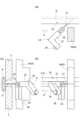
図1に示される溶接装置1は、建物の施工現場において、柱部品3同士の溶接を行うための現場溶接装置である。柱部品3は例えば角形の鋼管であり、複数の柱部品3が鉛直方向に重ねられ互いに溶接されることで角形の鋼管柱が構築される。溶接される柱部品3,3同士は、互いの材軸を一致させ、柱部品3,3の水平な端部同士が全周に亘って近接し対向するように配置される。この端部同士が対向する箇所に開先Wが形成され、開先Wは、柱部品3の全周に亘って水平面内に延在している。 A
開先Wの近傍において、柱部品3,3の4つの外壁面の各中央部には、それぞれエレクションピース4が予め溶接されている。上の柱部品3に設けられたエレクションピース4と、下の柱部品3に設けられたエレクションピース4とが鉛直方向に並び、開先Wを跨ぐ建方治具5によって互いに接続されている。このようなエレクションピース4及び建方治具5により、溶接前の柱部品3,3同士が仮接続されている。 In the vicinity of the groove W, an
溶接装置1は、レール11と、レール11上を移動可能な溶接ロボット13と、溶接ロボット13を制御する制御部15と、を備えている。レール11は、柱部品3,3の全周を囲む円環状をなしており、所定の固定具11aを介して下側の柱部品3に支持されている。レール11には溶接ロボット13を搭載するとともにレール11上を走行するキャリッジ17が取り付けられている。溶接ロボット13のアーム先端には、溶接用エンドエフェクタとしての溶接トーチ21と、溶接中において溶接トーチ21の直前の開先形状をセンシングする開先センサ23と、が搭載されている。制御部15は、レール11上における溶接ロボット13の移動(キャリッジ17の走行)、溶接ロボット13のアーム13aの駆動、溶接トーチ21の溶接動作、開先センサ23のセンシング動作等を統合的に制御するコンピュータシステムである。 The
図2は溶接ロボット13の側面図である。溶接ロボット13は6軸垂直多関節ロボットであり、溶接ロボット13のアーム13aは、キャリッジ17に固定されるベースL0(架台)と、ベースL0に対して第1軸線J1周りに旋回可能な第1リンクL1と、第1リンクL1に対して第2軸線J2周りに回転可能な第2リンクL2と、第2リンクL2に対して第3軸線J3周りに回転可能な第3リンクL3と、第3リンクL3に対して第4軸線J4周りに回転可能な第4リンクL4と、第4リンクL4に対して第5軸線J5周りに回転可能な第5リンクL5と、第5リンクL5に対して第6軸線J6周りに回転可能な最先端リンクL6と、を備えている。なお、上記の軸線J1,J4,J6は図2の紙面に平行な軸線であり、軸線J2,J3,J5は図2の紙面に直交する軸線である。 FIG. 2 is a side view of the
溶接ロボット13は、各リンクL1~L6をそれぞれ回転させるモータ等の駆動源(図示せず)を備えており、当該駆動源は制御部15の制御信号に従って動作する。最先端リンクL6には、前述の溶接トーチ21及び開先センサ23が搭載されており。制御部15が各リンクL1~L6の回転を制御することにより、溶接トーチ21及び開先センサ23の位置及び姿勢が制御される。 The
溶接装置1で実行される柱部品3,3の溶接の概要は次のとおりである。柱部品3,3同士の間には、柱部品3,3の内壁面に設置された裏当金物6と、2つの柱部品3の端面とで囲まれた開先Wが予め形成されている(図4(c)参照)。キャリッジ17がレール11上の所定の位置に配置され固定された状態において、制御部15の制御下で溶接ロボット13のアーム13aが駆動され溶接トーチ21が移動される。制御部15は、溶接トーチ21の先端を開先W内で当該開先Wの延在方向に水平に移動させながら、溶接トーチ21先端の移動軌跡上に溶接ビードを形成していく。上記のような溶接トーチ21先端の移動軌跡は、事前に計測された開先Wの形状に基づいて予め設定されている。この開先Wの事前の計測は、溶接ロボット13及び開先センサ23を利用して実行されてもよい。 The outline of the welding of the
また、上記の溶接中において、開先センサ23は、溶接トーチ21の進行方向の直前の開先Wの形状をセンシングし、センシング情報を制御部15に送出する。制御部15は、前述のように開先Wの延在方向に溶接トーチ21を移動させながら、上記センシング情報に基づき、溶接直前の開先Wの断面形状に応じて、溶接トーチ21の先端の位置(狙い位置)を開先Wの断面内で微調整する。このような微調整により開先W内の適切な位置に溶接ビードが形成される。上記のような溶接トーチ21の移動が複数回繰り返されて開先W内が複数の溶接ビードで充填されることにより開先Wの溶接が完成する。 Further, during the above-described welding, the
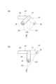
図2及び図3を参照し、溶接ロボット13の最先端リンクL6について説明する。図3(b)は溶接ロボット13の最先端リンクL6を図2の矢印A方向から回転軸線J6に平行な視線で見た正面図である。図3(a)はその最先端リンクL6の平面図、図3(c)はその最先端リンクL6の側面図である。最先端リンクL6は、リンク本体部27と、前述の溶接トーチ21及び開先センサ23と、を備えている。リンク本体部27は、第5リンクL5(架台側のリンク)に対して回転軸線J6周りに回転可能に接続されている。 The most advanced link L6 of the
溶接トーチ21は棒状をなしリンク本体部27に固定されている。開先センサ23は、直方体状のセンサ筐体29内に収納され当該センサ筐体29内で固定されている。センサ筐体29はブラケット24を介して溶接トーチ21に固定されている。溶接トーチ21及び開先センサ23は、リンク本体部27に対して移動(並進移動及び回転移動)できないように固定されており、溶接トーチ21、開先センサ23、リンク本体部27及びセンサ筐体29は、溶接ロボット13のアーム13aの駆動中において互いの位置関係を変えない。 The
最先端リンクL6における溶接トーチ21、開先センサ23及びリンク本体部27の位置関係について説明する。溶接トーチ21は回転軸線J6に平行な姿勢でリンク本体部27に取り付けられ回転軸線J6に対しオフセットされて配置されている。すなわち、溶接トーチ21は、回転軸線J6と平行に延在するとともに、回転軸線J6からずれた位置に配置されている。このように溶接トーチ21が回転軸線J6からオフセットされていることにより、溶接トーチ21のケーブル類(例えば、溶接トーチ21に溶接材を供給する供給管)を、溶接トーチ21の後方に引き出し易い。 The positional relationship between the
開先センサ23は、溶接トーチ21から当該溶接トーチ21の延在方向に直交する方向(溶接トーチ21の径方向)に離れて位置している。例えば、図3(b)の視線で見れば、溶接トーチ21が回転軸線J6から上方にオフセットされており、開先センサ23は、溶接トーチ21から左斜め下方にずれた位置に位置している。換言すれば、図3(b)に示されるように回転軸線J6に平行な視線で見て、溶接トーチ21を起点とする開先センサ23の方向(矢印B1で示す)と、溶接トーチ21を起点とする回転軸線J6の方向(矢印B2で示す)と、が角度αをなして交差しており、角度αは鋭角である(0°<α<90°)。本実施形態では、角度αは45°に設定されている。溶接トーチ21と開先センサ23との上記のような位置関係により、開先センサ23を収納するセンサ筐体29は溶接トーチ21から矢印B1方向に張出している。開先センサ23に対する溶接の熱の悪影響を回避するために、開先センサ23及びセンサ筐体29は溶接トーチ21の先端から比較的離れて位置しており、溶接トーチ21は、センサ筐体29の位置から更に所定の長さで延び出している。 The
開先センサ23は、例えば、開先W側に向けて当該開先Wを上下に横切るようにレーザ光を走査するレーザ光走査部と、上記レーザ光の反射光を撮像する反射光撮像部と、を備えるものであり、この反射光の画像に基づいて開先Wの断面形状を示す情報が前述のセンシング情報として取得される。このタイプの開先センサ23では、レーザ光走査部と反射光撮像部とが開先Wの延在方向に並んで配置される必要がある。従って、開先センサ23の開先W延在方向のサイズはある程度大きくならざるを得ず、その結果、開先センサ23を収納するセンサ筐体29の矢印B1方向への張出し量もある程度大きくならざるを得ない。 The
続いて、上述の溶接装置1により実行される本実施形態の溶接方法について説明する。この溶接方法では、図1に示されるように、開先Wのうち2つの隣接する建方治具5同士の間の区間T(以下「溶接区間T」)が溶接される。このような溶接方法が建方治具5の数と同じ回数(例えば4回)繰り返して実行されることで、柱部品3,3の溶接が完成する。以下では、この溶接方法において、上記溶接区間Tの開先W内に1本の溶接ビードを形成する溶接作業について説明する。また、溶接区間Tの両端に位置する2つの建方治具5を区別する場合には、図1に示されるように、溶接区間Tの右端に位置するものを建方治具5a、左端に位置するものを建方治具5bと呼ぶ。 Next, the welding method of this embodiment executed by the above-mentioned
溶接作業は、溶接区間Tの右端から左端まで左向きに進行する。図1に示されるように溶接区間Tを3つの区間T1,T2,T3に分けて考えると、溶接作業は、最初に右側の建方治具5a近傍の区間T1で開先Wを溶接する第1段階と、第1段階の後に建方治具5の影響がない区間T2で開先Wを溶接する第2段階と、第2段階の後に左側の建方治具5b近傍の区間T3で開先Wを溶接する第3段階と、を含んでいる。以下で説明する溶接作業中の最先端リンクL6の動き(並進移動、回転、姿勢の変更等)は、制御部15において所定の溶接制御プログラムが実行され、前述したように制御部15の制御下で溶接ロボット13がアーム13aを駆動することにより実現される。 The welding operation progresses leftward from the right end of the welding section T to the left end. If the welding section T is divided into three sections T1, T2, and T3 as shown in FIG. 1 stage, a 2nd stage in which the groove W is welded in a section T2 where there is no influence of the
(第2段階)
まず、図4を参照し、建方治具5の影響がない区間T2で実行される第2段階について説明する。図4(b)は、第2段階の溶接中の最先端リンクL6及び開先Wを、溶接に係る柱部品3,3の外壁面に直交する視線で見た正面図である。また、図4(a)はその平面図、図4(c)はその左側面図である。図4においては、溶接ロボット13の他のリンクL1~L5の図示は省略されている。(Second stage)
First, with reference to FIG. 4, the second stage executed in the section T2 where there is no influence of the
ここでは、溶接中の溶接トーチ21を水平姿勢とする例を示しているが、溶接中の溶接トーチ21を水平面に対して上向き又は下向きに傾斜させてもよい。またここでは、溶接中の溶接トーチ21を進行方向に対して直交する姿勢としているが、溶接トーチ21を進行方向の前方又は後方に傾斜させてもよい。図4に示されるように、溶接中に溶接ビードが形成される予定の仮想的なラインを「溶接ラインD」とし、当該溶接ラインDと溶接中の溶接トーチ21の中心軸線とを含む仮想的な平面を「仮想平面S」とする。 Here, an example is shown in which the
第2段階では、図4に示されるように、最先端リンクL6は、開先センサ23が溶接トーチ21の進行方向前方に位置する状態を維持しながら、溶接トーチ21の先端が溶接ラインD上を通過するように矢印H方向に移動する。すなわち、溶接トーチ21と開先センサ23とが仮想平面S内に並ぶような最先端リンクL6の姿勢を維持しながら、最先端リンクL6が溶接ラインDに平行に並進移動する。ここでは、溶接トーチ21から進行方向前方に向けてセンサ筐体29が張出し、その張出方向は溶接ラインDに平行である。最先端リンクL6がこのような姿勢で移動することにより、開先センサ23は、溶接トーチ21の進行方向の直前の(例えば数cm前方の)開先Wの形状をセンシングしてセンシング情報を取得することが可能である。そして、前述したように、当該センシング情報に基づいて、溶接トーチ21の狙い位置が溶接中に微調整される。 In the second stage, as shown in FIG. 4, the tip of the
(第1段階)
続いて、図5を参照し第1段階について説明する。図4と同様に、図5(b)は、第1段階の溶接中の最先端リンクL6及び開先Wの正面図であり、図5(a)はその平面図、図5(c)はその左側面図である。溶接区間Tの右端に建方治具5aが存在するので、第1段階では、図に示されるように、溶接トーチ21を進行方向後方に傾け、建方治具5aの奥側の開先Wに溶接トーチ21が斜めに挿入される。このとき仮に、第2段階と同様に開先センサ23が仮想平面S内に存在すれば、柱部品3の側壁面又は開先Wの内側面にセンサ筐体29が干渉する虞がある。(1st stage)
Next, the first stage will be explained with reference to FIG. Similar to FIG. 4, FIG. 5(b) is a front view of the leading edge link L6 and groove W during welding in the first stage, FIG. 5(a) is a plan view thereof, and FIG. 5(c) is It is a left side view. Since the
そこで、この干渉を回避するため、図5に示されるように、最先端リンクL6の姿勢を、溶接トーチ21と開先センサ23とが仮想平面Sに交差する方向に並ぶような姿勢とする。すなわち、第1段階の溶接中における開先センサ23は仮想平面S上から面外方向にずれた位置に配置される。具体的には、図5に示される例では、溶接トーチ21と開先センサ23との並び方向(図3の矢印B1方向)が仮想平面Sに直交し、センサ筐体29は溶接トーチ21から鉛直下方に延びる状態になる。そして、この姿勢の最先端リンクL6が左方に移動しながら建方治具5aの奥側の開先Wの溶接が行われる。その後、建方治具5aの影響がない位置まで最先端リンクL6が移動したところで、溶接トーチ21を中心軸として最先端リンクL6が回転され、溶接トーチ21と溶接ラインDとがなす角度が変更されて、前述の第2段階に移行される。 Therefore, in order to avoid this interference, as shown in FIG. 5, the posture of the leading edge link L6 is set so that the
(第3段階)
続いて、図6を参照し第3段階について説明する。図4と同様に、図6(b)は、第3段階の溶接中の最先端リンクL6及び開先Wの正面図であり、図6(a)はその平面図、図6(c)はその右側面図である。第2段階の溶接中に、溶接区間Tの左端の建方治具5bが近づいたところで第3段階に移行される。第3段階では、図に示されるように、溶接トーチ21を進行方向前方に傾け、建方治具5bの奥側の開先Wに溶接トーチ21が斜めに挿入される。このとき仮に、第2段階と同様に開先センサ23が仮想平面S内に存在すれば、建方治具5bにセンサ筐体29が干渉する虞がある。(Third stage)
Next, the third stage will be explained with reference to FIG. Similar to FIG. 4, FIG. 6(b) is a front view of the leading edge link L6 and groove W during welding in the third stage, FIG. 6(a) is a plan view thereof, and FIG. 6(c) is FIG. During the second stage of welding, when the
そこで、この干渉を回避するため、第1段階と同様にして、図6に示されるように、最先端リンクL6の姿勢を、溶接トーチ21と開先センサ23とが仮想平面Sに交差する方向に並ぶような姿勢とする。すなわち、第3段階の溶接中における開先センサ23は仮想平面S上から面外方向にずれた位置に配置される。具体的には、図6に示される例では、溶接トーチ21と開先センサ23との並び方向(図3の矢印B1方向)が、仮想平面Sに直交し、センサ筐体29は、溶接トーチ21から鉛直下方に延びる状態になる。そして、この姿勢の最先端リンクL6が左方に移動しながら建方治具5bの奥側の開先Wの溶接が行われる。 Therefore, in order to avoid this interference, in the same way as in the first step, the posture of the leading edge link L6 is changed in the direction in which the
なお、上述のような第1段階及び第3段階においては、開先センサ23が開先Wに対面していない。従って当然ながら、開先センサ23が前述したようなセンシング情報を取得することは不可能であり、溶接トーチ21の狙い位置の微調整は行われない。 Note that in the first and third stages as described above, the
上述した本実施形態の溶接装置1及び溶接方法による作用効果について説明する。この溶接方法では、建方治具5の奥側の開先Wを溶接すべく、建方治具5の近傍では、溶接トーチ21の先端を建方治具5の奥側に挿入する必要がある。このとき、仮想平面Sに投影して見た場合、溶接トーチ21は進行方向Hの前方又は後方に傾く必要がある。そして、この傾きに起因して、溶接トーチ21と一緒に最先端リンクL6に固定されたセンサ筐体29が、柱部品3,3、開先W、又は建方治具5に干渉する虞がある。 The effects of the
これに対し、本実施形態の溶接方法では、建方治具5の近傍の溶接を行う第1段階及び第3段階において、最先端リンクL6の姿勢は、溶接トーチ21と開先センサ23とが仮想平面Sに交差(例えば直交)する方向に並ぶような姿勢とされる(第2溶接工程)。この姿勢によれば、仮想平面Sに投影して見た場合に、溶接トーチ21からのセンサ筐体29の張出し量は、第2段階と比較して小さくなる。その結果、溶接トーチ21を上記のように仮想平面S内で傾けた場合に、この傾きに伴ってセンサ筐体29が干渉する範囲は狭くなり、その結果、上記傾きに起因してセンサ筐体29が柱部品3,3等に干渉する可能性が低減される。 On the other hand, in the welding method of this embodiment, in the first and third stages of welding near the
特に、図5及び図6に例示されているように、第1段階及び第3段階において、溶接トーチ21と開先センサ23との並び方向が仮想平面Sに直交する場合に上記の作用効果が顕著であるので、第1段階及び第3段階においては、溶接トーチ21と開先センサ23との並び方向が仮想平面Sに略直交するようにすることが好ましい。 In particular, as illustrated in FIGS. 5 and 6, the above effects are achieved when the alignment direction of the
その一方で、建方治具5の影響がない第2段階では、溶接トーチ21と開先センサ23とが仮想平面S上に並び(第1溶接工程)、開先センサ23が溶接トーチ21の進行方向前方に位置するので、開先センサ23を機能させることができ、前述したような溶接トーチ21の狙い位置の微調整を実行することができる。 On the other hand, in the second stage where there is no influence from the
溶接装置1では、回転軸線J6からの溶接トーチ21のオフセット方向と、溶接トーチ21からのセンサ筐体29(開先センサ23)の張出し方向と、が、図3(b)に示すような関係にあり、図中の角度αが鋭角(例えば45°)である。ここで比較のために、図7(b)に示されるように、仮に、角度αが90°である場合を考える。図7(b)は最先端リンクL6を回転軸線J6に平行な視線で見た状態を示し、図中の実線は第2段階、図中の二点鎖線は第1及び第3段階を示す。また、最先端リンクL6の下方に位置する図中の点Cは、溶接ロボット13のロボット原点を示す。 In the
図7(b)の形態では、第2段階と第1及び第3段階との間で、ロボット原点Cと回転軸線J6との距離の変動(E3-E2)は比較的大きい。そうすると、第1及び第3段階においては、回転軸線J6がロボット原点Cから大きく離れ、溶接トーチ21の到達距離が不足する可能性もある。これに対し、本実施形態では、図7(a)に示されるように角度αが45°であるので、幾何学的に理解されるように、第2段階と第1及び第3段階との間で、ロボット原点Cと回転軸線J6との距離の変動(E3-E2)は比較的小さい。その結果、ロボット原点Cからの溶接トーチ21の到達距離が不足する可能性が低減される。このような効果を効率的に得るために、角度αが30~60°であることが好ましく、角度αが略45°であれば更に好ましい。 In the form of FIG. 7(b), the variation (E3-E2) in the distance between the robot origin C and the rotation axis J6 is relatively large between the second stage and the first and third stages. Then, in the first and third stages, the rotational axis J6 will be far away from the robot origin C, and there is a possibility that the reachable distance of the
本発明は、上述した実施形態を始めとして、当業者の知識に基づいて種々の変更、改良を施した様々な形態で実施することができる。また、上述した実施形態に記載されている技術的事項を利用して、実施例の変形例を構成することも可能である。各実施形態の構成を適宜組み合わせて使用してもよい。 The present invention can be implemented in various forms including the embodiments described above, with various changes and improvements based on the knowledge of those skilled in the art. Further, it is also possible to configure a modified example of the embodiment by using the technical matters described in the embodiment described above. The configurations of each embodiment may be used in combination as appropriate.
溶接トーチ21から径方向に離れて位置するセンサとしては、開先センサ23に代えて、溶接中の溶接対象物の情報を取得するための他種のセンサが設けられてもよい。他種のセンサとしては、溶接中の溶融池の状態をセンシングする溶融池センサや、溶接中における柱部品3,3の外壁面の温度をセンシングする温度センサ等が挙げられる。上記他種のセンサは、溶接中における溶接トーチ21の進行方向後方に位置してもよい。また、開先センサ23と他種のセンサとの両方が最先端リンクL6に搭載されてもよく、この場合、溶接トーチ21の進行方向前方に開先センサ23が位置するとともに、溶接トーチ21の進行方向後方に他種のセンサが位置するようにしてもよい。 As the sensor located radially apart from the
上述の実施形態では、鋼管柱の突き合わせ溶接に本発明の溶接方法及び溶接装置が適用されているが、本発明の溶接方法及び溶接装置は、鋼管柱以外の部材の溶接に適用することもでき、また、突き合わせ溶接以外の形態の溶接(例えば隅肉溶接)を行う場合に適用することもできる。また、本発明の溶接方法及び溶接装置は、上述の実施形態に示したように溶接トーチ21をエンドエフェクタとする自動アーク溶接に限らず、レーザノズルをエンドエフェクタとするレーザ溶接にも適用することができる。 In the embodiments described above, the welding method and welding device of the present invention are applied to butt welding of steel pipe columns, but the welding method and welding device of the present invention can also be applied to welding members other than steel pipe columns. Moreover, it can also be applied to cases where welding in a form other than butt welding (for example, fillet welding) is performed. Further, the welding method and welding apparatus of the present invention can be applied not only to automatic arc welding using the
なお、溶接トーチ21に代えて開先Wを清掃するための開先清掃ツールがロボット13のエンドエフェクタとして装着され、開先Wの自動清掃が行われる場合がある。この自動清掃では、ロボット13が開先清掃ツールを開先Wに沿って移動させ、建方治具5の近傍においては、建方治具5の奥側の開先Wに開先清掃ツールが斜めに挿入される。このような自動清掃においても、ロボット13の最先端リンクL6に前述の第1~第3段階と同様の動きをさせてもよい。 Note that instead of the
1…溶接装置、3…柱部品(溶接対象物)、13…溶接ロボット、13a…アーム、21…溶接トーチ(エンドエフェクタ)、23…開先センサ(センサ)、D…溶接ライン、L5…第5リンク(架台側のリンク)、L6…最先端リンク、J6…回転軸線、S…仮想平面。 DESCRIPTION OF
Claims (3)
Translated fromJapanese前記溶接ロボットのアームの最先端のリンクは、架台側のリンクに対して所定の回転軸線周りに回転可能に接続され、前記エンドエフェクタと、前記エンドエフェクタの延在方向に直交する方向に前記エンドエフェクタから離れて位置し溶接中の前記溶接対象物の情報を取得するためのセンサと、を搭載しており、
前記最先端のリンクを、前記エンドエフェクタと前記センサとが前記溶接ラインを含む平面内に並ぶような姿勢にして溶接を行う第1溶接工程と、
前記最先端のリンクを、前記エンドエフェクタと前記センサとが前記溶接ラインを含む平面に交差する方向に並ぶような姿勢にして溶接を行う第2溶接工程と、を備える、溶接方法。 A welding method in which a welding robot moves a welding end effector on a welding line to weld a welding target, the welding method comprising:
The most advanced link of the arm of the welding robot is rotatably connected to the link on the pedestal side around a predetermined rotational axis, and is connected to the end effector in a direction perpendicular to the extending direction of the end effector. Equipped with a sensor located away from the effector for acquiring information on the welding target during welding,
a first welding step in which the most advanced link is welded in a position such that the end effector and the sensor are aligned in a plane that includes the welding line;
A welding method comprising: a second welding step in which the most advanced link is welded in a posture such that the end effector and the sensor are lined up in a direction intersecting a plane including the welding line.
前記エンドエフェクタが前記回転軸線からずれた位置で前記回転軸線と平行に配置されており、
前記回転軸線に平行な視線で見て、前記エンドエフェクタを起点とする前記センサの方向と、前記エンドエフェクタを起点とする前記回転軸線の方向と、が鋭角をなして交差している、請求項1に記載の溶接方法。 In the cutting edge link,
the end effector is arranged parallel to the rotation axis at a position offset from the rotation axis;
When viewed from a line of sight parallel to the rotational axis, the direction of the sensor starting from the end effector and the direction of the rotational axis starting from the end effector intersect at an acute angle. 1. The welding method described in 1.
前記溶接ロボットのアームの最先端のリンクは、架台側のリンクに対して所定の回転軸線周りに回転可能に接続され、前記エンドエフェクタと、前記エンドエフェクタの延在方向に直交する方向に延在するとともに前記エンドエフェクタから離れて位置し溶接中の前記溶接対象物の情報を取得するためのセンサと、を搭載しており、
前記最先端のリンクでは、
前記エンドエフェクタが前記回転軸線からずれた位置で前記回転軸線と平行に配置されており、
前記回転軸線に平行な視線で見て、前記エンドエフェクタを起点とする前記センサの方向と、前記エンドエフェクタを起点とする前記回転軸線の方向と、が鋭角をなして交差している、溶接装置。 A welding devicecapable of welding objects to be welded by moving a welding end effector on a welding line by a welding robot, and in this welding, the end effector can be tilted forward or backward in the direction of movement. And,
The most advanced link of the arm of the welding robot is rotatably connected to the link on the pedestal side about a predetermined rotation axis, andextends in a direction perpendicular to the end effector and the direction in which the end effector extends.and a sensor located away from the end effector for acquiring information on the welding object being welded,
In the cutting edge link,
the end effector is arranged parallel to the rotation axis at a position offset from the rotation axis;
A welding device in which the direction of the sensor starting from the end effector and the direction of the rotation axis starting from the end effector intersect at an acute angle when viewed from a line of sight parallel to the rotation axis. .
Priority Applications (1)
| Application Number | Priority Date | Filing Date | Title |
|---|---|---|---|
| JP2020141909AJP7438896B2 (en) | 2020-08-25 | 2020-08-25 | Welding method and welding equipment |
Applications Claiming Priority (1)
| Application Number | Priority Date | Filing Date | Title |
|---|---|---|---|
| JP2020141909AJP7438896B2 (en) | 2020-08-25 | 2020-08-25 | Welding method and welding equipment |
Publications (2)
| Publication Number | Publication Date |
|---|---|
| JP2022037665A JP2022037665A (en) | 2022-03-09 |
| JP7438896B2true JP7438896B2 (en) | 2024-02-27 |
Family
ID=80494728
Family Applications (1)
| Application Number | Title | Priority Date | Filing Date |
|---|---|---|---|
| JP2020141909AActiveJP7438896B2 (en) | 2020-08-25 | 2020-08-25 | Welding method and welding equipment |
Country Status (1)
| Country | Link |
|---|---|
| JP (1) | JP7438896B2 (en) |
Families Citing this family (2)
| Publication number | Priority date | Publication date | Assignee | Title |
|---|---|---|---|---|
| JP7607606B2 (en)* | 2022-03-15 | 2024-12-27 | 日鉄エンジニアリング株式会社 | Welding Systems |
| CN116967680A (en)* | 2023-02-13 | 2023-10-31 | 中铁十八局集团有限公司 | Rectangular cross-section steel component welding robot |
Citations (5)
| Publication number | Priority date | Publication date | Assignee | Title |
|---|---|---|---|---|
| JP2012016806A (en) | 2010-07-09 | 2012-01-26 | Kobe Steel Ltd | Welding robot |
| JP2013027966A (en) | 2011-07-29 | 2013-02-07 | Daihen Corp | Method and device for detecting welding position |
| JP2013525117A (en) | 2010-04-30 | 2013-06-20 | ソンギュ オ, | TIG welding equipment |
| WO2015146180A1 (en) | 2014-03-27 | 2015-10-01 | パナソニックIpマネジメント株式会社 | Robot control method |
| JP2020062675A (en) | 2018-10-19 | 2020-04-23 | 鹿島建設株式会社 | Filed welding method and filed welding device |
Family Cites Families (2)
| Publication number | Priority date | Publication date | Assignee | Title |
|---|---|---|---|---|
| JPH04250991A (en)* | 1990-12-29 | 1992-09-07 | Kawasaki Heavy Ind Ltd | Industrial robots and work methods using them |
| JPH08150476A (en)* | 1994-11-24 | 1996-06-11 | Fanuc Ltd | Method for confirming weld bead shape in welding robot using real time tracking sensor |
- 2020
- 2020-08-25JPJP2020141909Apatent/JP7438896B2/enactiveActive
Patent Citations (5)
| Publication number | Priority date | Publication date | Assignee | Title |
|---|---|---|---|---|
| JP2013525117A (en) | 2010-04-30 | 2013-06-20 | ソンギュ オ, | TIG welding equipment |
| JP2012016806A (en) | 2010-07-09 | 2012-01-26 | Kobe Steel Ltd | Welding robot |
| JP2013027966A (en) | 2011-07-29 | 2013-02-07 | Daihen Corp | Method and device for detecting welding position |
| WO2015146180A1 (en) | 2014-03-27 | 2015-10-01 | パナソニックIpマネジメント株式会社 | Robot control method |
| JP2020062675A (en) | 2018-10-19 | 2020-04-23 | 鹿島建設株式会社 | Filed welding method and filed welding device |
Also Published As
| Publication number | Publication date |
|---|---|
| JP2022037665A (en) | 2022-03-09 |
Similar Documents
| Publication | Publication Date | Title |
|---|---|---|
| US10835981B2 (en) | Method for circumferential welding and a robotic welding system for circumferential welding | |
| EP2177301B1 (en) | Welding equipment and welding method | |
| JP5864557B2 (en) | Method and apparatus for laser joining thin metal plate parts | |
| KR20190022755A (en) | Welding device | |
| JP7438896B2 (en) | Welding method and welding equipment | |
| JP6771288B2 (en) | Welding equipment and control method of welding equipment | |
| JPS6037273A (en) | Manipulator type welding apparatus | |
| JP6978350B2 (en) | Work posture adjustment method, model manufacturing method and manufacturing equipment | |
| WO2021024540A1 (en) | Welding control method and welding control device for portable welding robot, portable welding robot, and welding system | |
| JP2000317666A (en) | Laser welding equipment | |
| JP3726774B2 (en) | Laser welding equipment | |
| JP2010240664A (en) | Welding robot and method for controlling weaving operation in welding | |
| JP2019093423A (en) | Work-piece processing device | |
| JPS6333187A (en) | Laser welding equipment | |
| JP3224739B2 (en) | Automatic pipe welding equipment | |
| JP3073341B2 (en) | Robot positioning method and device | |
| JPH08132264A (en) | Laser processing machine | |
| JP7170806B1 (en) | Portable welding robot system | |
| JP7679032B2 (en) | Robot system for welding steel pipe columns | |
| JP7498141B2 (en) | WELDING SYSTEM, WELDING METHOD, WELDING ROBOT AND PROGRAM | |
| JPH115164A (en) | First layer welding method | |
| JP2021151661A (en) | Circumferential welding method | |
| JPH11320092A (en) | Nozzle automatic welding method | |
| JPH07185815A (en) | Kura type welding equipment | |
| JP7227332B1 (en) | Welding equipment and welding method |
Legal Events
| Date | Code | Title | Description |
|---|---|---|---|
| A521 | Request for written amendment filed | Free format text:JAPANESE INTERMEDIATE CODE: A523 Effective date:20200831 | |
| A621 | Written request for application examination | Free format text:JAPANESE INTERMEDIATE CODE: A621 Effective date:20230202 | |
| A131 | Notification of reasons for refusal | Free format text:JAPANESE INTERMEDIATE CODE: A131 Effective date:20231205 | |
| A977 | Report on retrieval | Free format text:JAPANESE INTERMEDIATE CODE: A971007 Effective date:20231207 | |
| A521 | Request for written amendment filed | Free format text:JAPANESE INTERMEDIATE CODE: A523 Effective date:20240119 | |
| TRDD | Decision of grant or rejection written | ||
| A01 | Written decision to grant a patent or to grant a registration (utility model) | Free format text:JAPANESE INTERMEDIATE CODE: A01 Effective date:20240206 | |
| A61 | First payment of annual fees (during grant procedure) | Free format text:JAPANESE INTERMEDIATE CODE: A61 Effective date:20240214 | |
| R150 | Certificate of patent or registration of utility model | Ref document number:7438896 Country of ref document:JP Free format text:JAPANESE INTERMEDIATE CODE: R150 |