JP7435614B2 - syringe pump - Google Patents
syringe pumpDownload PDFInfo
- Publication number
- JP7435614B2 JP7435614B2JP2021548921AJP2021548921AJP7435614B2JP 7435614 B2JP7435614 B2JP 7435614B2JP 2021548921 AJP2021548921 AJP 2021548921AJP 2021548921 AJP2021548921 AJP 2021548921AJP 7435614 B2JP7435614 B2JP 7435614B2
- Authority
- JP
- Japan
- Prior art keywords
- clamp
- tube
- accommodating
- barrel
- holding
- Prior art date
- Legal status (The legal status is an assumption and is not a legal conclusion. Google has not performed a legal analysis and makes no representation as to the accuracy of the status listed.)
- Active
Links
- 230000000694effectsEffects0.000description3
- 230000037431insertionEffects0.000description3
- 238000003780insertionMethods0.000description3
- 239000008155medical solutionSubstances0.000description3
- 238000010586diagramMethods0.000description2
- 238000004806packaging method and processMethods0.000description2
- 239000003814drugSubstances0.000description1
- 239000007788liquidSubstances0.000description1
Images


Classifications
- A—HUMAN NECESSITIES
- A61—MEDICAL OR VETERINARY SCIENCE; HYGIENE
- A61M—DEVICES FOR INTRODUCING MEDIA INTO, OR ONTO, THE BODY; DEVICES FOR TRANSDUCING BODY MEDIA OR FOR TAKING MEDIA FROM THE BODY; DEVICES FOR PRODUCING OR ENDING SLEEP OR STUPOR
- A61M39/00—Tubes, tube connectors, tube couplings, valves, access sites or the like, specially adapted for medical use
- A61M39/22—Valves or arrangement of valves
- A61M39/28—Clamping means for squeezing flexible tubes, e.g. roller clamps
- A—HUMAN NECESSITIES
- A61—MEDICAL OR VETERINARY SCIENCE; HYGIENE
- A61M—DEVICES FOR INTRODUCING MEDIA INTO, OR ONTO, THE BODY; DEVICES FOR TRANSDUCING BODY MEDIA OR FOR TAKING MEDIA FROM THE BODY; DEVICES FOR PRODUCING OR ENDING SLEEP OR STUPOR
- A61M5/00—Devices for bringing media into the body in a subcutaneous, intra-vascular or intramuscular way; Accessories therefor, e.g. filling or cleaning devices, arm-rests
- A61M5/14—Infusion devices, e.g. infusing by gravity; Blood infusion; Accessories therefor
- A61M5/142—Pressure infusion, e.g. using pumps
- A61M5/145—Pressure infusion, e.g. using pumps using pressurised reservoirs, e.g. pressurised by means of pistons
Landscapes
- Health & Medical Sciences (AREA)
- Heart & Thoracic Surgery (AREA)
- Hematology (AREA)
- Anesthesiology (AREA)
- Biomedical Technology (AREA)
- Engineering & Computer Science (AREA)
- Life Sciences & Earth Sciences (AREA)
- Animal Behavior & Ethology (AREA)
- General Health & Medical Sciences (AREA)
- Public Health (AREA)
- Veterinary Medicine (AREA)
- Vascular Medicine (AREA)
- Pulmonology (AREA)
- Infusion, Injection, And Reservoir Apparatuses (AREA)
Description
Translated fromJapaneseこの発明は、シリンジポンプに関する。 This invention relates to a syringe pump.
例えば、特開2019-10502号公報(以下、「特許文献1」という。)には、シリンジを駆動する駆動部を有するポンプ本体と、シリンジに接続されたチューブの流路の開閉を切り替える開閉ユニットと、を備えるシリンジポンプが開示されている。開閉ユニットは、チューブクリップと、ベースと、カバーと、を有している。 For example, Japanese Patent Application Publication No. 2019-10502 (hereinafter referred to as "Patent Document 1") discloses a pump body having a drive unit that drives a syringe, and an opening/closing unit that switches the opening and closing of a flow path of a tube connected to the syringe. A syringe pump is disclosed. The opening/closing unit includes a tube clip, a base, and a cover.
チューブクリップは、主としてサイフォニングを防止するための部材である。チューブクリップは、当該チューブクリップにチューブを挿通させた状態でチューブを保持することが可能である。チューブクリップは、チューブの流路を閉塞する姿勢と開放する姿勢とに切り替え可能である。ベースは、ポンプ本体に接続されている。ベースは、チューブが配置される溝部と、チューブクリップが配置される凹部と、チューブクリップの脱落防止用の壁部と、を有している。カバーは、ベースに対して回動可能に設けられている。カバーは、閉じた状態において、ベースとともにチューブクリップを収容している。カバーが閉じた状態において、ベースとカバーとの間には、チューブが位置する空間が確保されている。 The tube clip is a member mainly for preventing siphoning. The tube clip can hold the tube in a state where the tube is inserted through the tube clip. The tube clip can be switched between a position in which the flow path of the tube is closed and a position in which it is opened. The base is connected to the pump body. The base has a groove in which the tube is placed, a recess in which the tube clip is placed, and a wall for preventing the tube clip from falling off. The cover is rotatably provided with respect to the base. The cover accommodates the tube clip together with the base in the closed position. When the cover is closed, a space is provided between the base and the cover in which the tube is located.
一般に、チューブ及びクランプは、チューブの流路がクランプによって閉塞された状態が継続することに起因するチューブの塑性変形を防止するため、チューブの流路を開放する姿勢に保持されたクランプにチューブが挿通された状態で包装されることが多い。 In general, tubes and clamps are used to prevent plastic deformation of the tube caused by the tube's flow path remaining blocked by the clamp. It is often packaged with it inserted.
このため、特許文献1に記載されるシリンジポンプでは、医療従事者が、チューブ及びチューブクリップを包装容器から取り出した状態(チューブクリップによってチューブの流路が閉塞されていない状態)でチューブ及びチューブクリップをベースの凹部に装着した場合、サイフォニングが生じる懸念がある。 For this reason, in the syringe pump described in Patent Document 1, a medical worker removes the tube and tube clip from the packaging container (in a state in which the flow path of the tube is not blocked by the tube clip), and then removes the tube and tube clip from the packaging container. There is a concern that siphoning may occur if the base is installed in the recessed part of the base.
本発明の目的は、クランプを収容するクランプ収容部に対し、チューブの流路が開放された状態でチューブ及びクランプが組み付けられるのを抑制可能なシリンジポンプを提供することである。 SUMMARY OF THE INVENTION An object of the present invention is to provide a syringe pump that can prevent a tube and a clamp from being assembled into a clamp accommodating portion that accommodates a clamp in a state where the flow path of the tube is open.
この発明の一局面に従ったシリンジポンプは、シリンジを駆動する駆動部を有するポンプ本体と、前記シリンジに接続されたチューブ内の流路の開閉を切り替えるクランプであって、前記チューブを保持するベースと、前記ベースに接続されており、前記チューブ内の前記流路が閉塞されるように前記ベースとともに前記チューブを挟持する挟持姿勢と前記流路を開放させる開放姿勢との間で変位可能な挟持片と、を有する前記クランプを保持するクランプ保持部と、を備え、前記クランプ保持部は、前記クランプを収容可能で、かつ、前記ベースに保持された前記チューブの延びる方向と直交する直交方向の一方側に開口する形状を有するクランプ収容部と、前記クランプに保持された前記チューブを収容可能で、かつ、前記クランプ収容部の開口を通じて前記クランプを前記クランプ収容部へ組み付ける組付方向に沿って前記クランプに保持された前記チューブが通過するのを許容するように前記クランプ収容部と同じ側に開口する形状を有するチューブ収容部と、前記組付方向に前記クランプ収容部の一部と重なる重なり部と、を有し、前記重なり部は、前記挟持片が前記挟持姿勢であるときに、前記組付方向に沿った前記クランプ収容部への前記クランプの通過を許容し、かつ、前記挟持片が前記開放姿勢であるときに、前記組付方向に前記クランプの一部と重なることで前記クランプの前記クランプ収容部への組み付けを規制する。 A syringe pump according to one aspect of the present invention includes a pump body having a drive unit that drives a syringe, a clamp that switches opening and closing of a flow path in a tube connected to the syringe, and a base that holds the tube. and a clamp connected to the base and movable between a clamping position in which the tube is clamped together with the base so as to close the flow passage in the tube, and an open position in which the flow passage is opened. a clamp holding part for holding the clamp, the clamp holding part being capable of accommodating the clamp and extending in an orthogonal direction perpendicular to the extending direction of the tube held on the base. a clamp accommodating part having a shape that is open on one side; and a clamp accommodating part capable of accommodating the tube held by the clamp, and along an assembly direction in which the clamp is assembled to the clamp accommodating part through the opening of the clamp accommodating part. A tube accommodating part having a shape that opens on the same side as the clamp accommodating part so as to allow the tube held by the clamp to pass through, and an overlap that overlaps with a part of the clamp accommodating part in the assembly direction. , the overlapping portion allows passage of the clamp to the clamp accommodating portion along the assembly direction when the clamping piece is in the clamping posture, and When in the open position, the clamp overlaps a part of the clamp in the assembly direction, thereby restricting assembly of the clamp to the clamp accommodating portion.
この発明によれば、クランプを保持するクランプ保持部に対し、チューブの流路が開放された状態でチューブ及びクランプが組み付けられるのを抑制可能なシリンジポンプを提供することができる。 According to the present invention, it is possible to provide a syringe pump that can prevent a tube and a clamp from being assembled to a clamp holding part that holds the clamp in a state where the flow path of the tube is open.
この発明の実施の形態について、図面を参照して説明する。なお、以下で参照する図面では、同一またはそれに相当する部材には、同じ番号が付されている。 Embodiments of the invention will be described with reference to the drawings. In addition, in the drawings referred to below, the same numbers are attached to the same or corresponding members.
(第1実施形態)
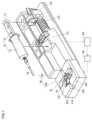
図1は、本発明の第1実施形態のシリンジポンプの全体構成とシリンジポンプに装着されるシリンジとを概略的に示す斜視図である。 (First embodiment)
FIG. 1 is a perspective view schematically showing the overall configuration of a syringe pump according to a first embodiment of the present invention and a syringe attached to the syringe pump.
シリンジ10は、薬液を収容可能なバレル12と、バレル12内から薬液を押し出すことが可能なプランジャ14と、を有している。バレル12の先端部には、チューブ20が接続されている。プランジャ14の後端部には、被押圧部15が形成されている。 The
図1に示されるように、本実施形態のシリンジポンプ40は、ポンプ本体100と、クランプ保持部200と、を有している。 As shown in FIG. 1, the
ポンプ本体100は、シリンジ10からチューブ20に少量の薬液を正確に投与可能な機器である。ポンプ本体100は、バレル受け部110と、プランジャ受け部120と、駆動部130と、切り替え機構140と、制御部150と、を有している。 The
バレル受け部110は、バレル12を受ける部位である。バレル受け部110は、バレル12を検出可能に構成されている。例えば、バレル受け部110は、バレル12によって押圧されたことを検出するセンサによってバレル12を検出していてもよい。 The
プランジャ受け部120は、プランジャ14を受ける部位である。プランジャ受け部120は、プランジャ14を検出可能に構成されている。例えば、プランジャ受け部120は、プランジャ14の被押圧部15によって押圧されたことを検出するセンサによってプランジャ14を検出していてもよい。
駆動部130は、シリンジ10を駆動する。駆動部130は、バレル12がバレル受け部110に受けられ、プランジャ14がプランジャ受け部120に受けられた状態において、バレル12に対してプランジャ14を押し込む。 The
制御部150は、切り替え機構140を制御する。切り替え機構140及び制御部150については、後述する。
クランプ保持部200は、クランプ30を保持する部位である。まず、図2及び図3を参照しながら、クランプ30について説明する。 The
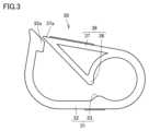
クランプ30は、チューブ20内の流路の開閉を切り替える部材である。クランプ30は、ベース31と、挟持片36と、を有している。 The
ベース31は、チューブ20を保持する部位である。ベース31は、第1基部32と、第1挟持突起33と、を有している。 The
第1基部32は、板状に形成されており、湾曲する形状を有している。第1基部32には、チューブ20を挿通させる挿通孔32hが形成されている。第1基部32は、挿通孔32hにチューブ20を挿通させた状態でチューブ20を保持する。第1基部32の先端部は、係止部32aを構成している。 The
第1挟持突起33は、チューブ20を挟持する部位である。第1挟持突起33は、第1基部32の内側面に接続されている。 The
挟持片36は、ベース31に接続されている。挟持片36は、チューブ20内の流路が閉塞されるようにベース31とともにチューブ20を挟持する挟持姿勢と、チューブ20内の流路を開放させる開放姿勢(図2に示される姿勢)と、の間で変位可能である。挟持片36は、第2基部37と、第2挟持突起38と、を有している。 The holding
第2基部37は、第1基部32の一端部(係止部32aと反対側の端部)に接続されている。第2基部37の先端部は、係止部32aに係合する被係止部37aを構成している。 The
第2挟持突起38は、第2基部37の内側面に接続されている。第2挟持突起38は、第1挟持突起33とともにチューブ20を挟持する部位である。具体的に、被係止部37aが係止部32aに係合することにより、挟持片36は、挟持姿勢となる。これにより、第1挟持突起33及び第2挟持突起38は、チューブ20内の流路を閉塞させる。一方、被係止部37aが係止部32aから離脱することにより、挟持片36は、開放姿勢となる。これにより、第1挟持突起33及び第2挟持突起38は、チューブ20内の流路を開放させる。 The
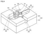
次に、図4~図7を参照しながら、クランプ保持部200について説明する。クランプ保持部200は、ポンプ本体100に接続されている。クランプ保持部200は、挟持片36が挟持姿勢である状態のクランプ30の当該クランプ保持部200への組み付けを許容する一方、挟持片36が開放姿勢である状態のクランプ30の当該クランプ保持部200への組み付けを規制する。クランプ保持部200は、クランプ収容部202と、チューブ収容部204と、重なり部221と、指回避部206と、を有している。 Next, the
クランプ収容部202は、クランプ30を収容する部位である。クランプ収容部202は、ベース31に保持されたチューブ20の延びる方向と直交する直交方向(図4における上下方向)の一方側(図4における上側)に開口する形状を有している。 The
チューブ収容部204は、クランプ30に保持されたチューブ20を収容する部位である。チューブ収容部204は、クランプ収容部202の開口を通じてクランプ30をクランプ収容部202へ組み付ける組付方向(図4における下向き)に沿ってクランプ30に保持されたチューブ20が通過するのを許容するようにクランプ収容部202と同じ側に開口する形状を有している。チューブ収容部204は、クランプ収容部202につながっている。チューブ収容部204は、クランプ収容部202に収容されたクランプ30に保持されたチューブ20の延びる方向(以下、第1方向と表記する。)におけるクランプ収容部202の両側に設けられている。 The tube
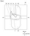
重なり部221は、組付方向(図6における紙面奥行き方向)にクランプ収容部202の一部と重なっている。図6に示されるように、重なり部221は、挟持片36が開放姿勢であるときに、組付方向にクランプ30の一部(挟持片36)と重なることでクランプ30のクランプ収容部202への組み付けを規制する。一方、図7に示されるように、重なり部221は、挟持片36が挟持姿勢であるときに、組付方向に沿ったクランプ収容部202へのクランプ30の通過を許容する。図6に示されるように、重なり部221は、第1方向に沿ってチューブ収容部204を延長した経路上から、組付方向及び第1方向の双方に直交する第2方向(図6における上下方向)に退避している。 The overlapping
指回避部206は、挟持姿勢であるクランプ30を医療従事者が組付方向に沿ってクランプ収容部202に組み付ける際に医療従事者の指を回避する部位である。指回避部206は、第2方向にクランプ収容部202を挟む位置に設けられている。第2方向におけるクランプ収容部202の一方側(図6における上側)に設けられた指回避部206は、第1方向に重なり部221に隣接している。 The
本実施形態では、クランプ保持部200は、ケース210と、カバー220と、を有している。 In this embodiment, the
図4及び図5に示されるように、ケース210は、前記クランプ収容部202と、受け溝214と、指逃げ部216と、を有している。 As shown in FIGS. 4 and 5, the
受け溝214は、クランプ収容部202に収容されたクランプ30に保持されたチューブ20を受ける部位である。 The receiving
指逃げ部216は、医療従事者の指を受け入れる形状を有している。指逃げ部216は、第2方向にクランプ収容部202を挟む位置に設けられている。 The
カバー220は、ケース210に対して着脱可能である。カバー220は、前記重なり部221と、スリット224と、指逃げ部226と、を有している。 Cover 220 is removable from
スリット224は、組付方向に沿ってチューブ20が通過するのを許容する。スリット224は、組付方向に受け溝214と重なる位置に設けられている。スリット224は、受け溝214とともに前記チューブ収容部204を構成している。カバー220は、スリット224により、重なり部221を含む部材と重なり部221を含まない部材とに分割されている。 The
指逃げ部226は、組付方向に指逃げ部216と重なる位置に設けられており、医療従事者の指を受け入れる形状を有している。指逃げ部226は、指逃げ部216とともに前記指回避部206を構成している。 The
カバー220のうち重なり部221を含む部材には、組付方向への係止部32aの通過を許容する切り欠き228が設けられている。切り欠き228は、第1方向において重なり部221を基準として指逃げ部226が設けられた側とは反対側に設けられている。 A
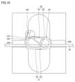
ここで、図8~図10を参照しながら、切り替え機構140及び制御部150について説明する。 Here, the
切り替え機構140は、クランプ30を挟持姿勢と開放姿勢とに切り替え可能である。切り替え機構140は、カム142と、モータ144(図1及び図5を参照)と、を有している。カム142及びモータ144の構成は、特開2019-10502号公報に記載される構成と同様であるため、これらの説明を簡略化する。すなわち、カム142は、図8に示される状態から組付方向(図8における紙面奥行き方向)と平行な軸まわりに回転することにより、図9に示されるように、被係止部37aが係止部32aに係合するように挟持片36を押圧する。カム142は、図9に示される状態からさらに前記軸まわりに回転することにより、被係止部37aが係止部32aから離脱するように係止部32aを押圧する。モータ144は、カム142が前記軸まわりに回転するようにカム142を駆動する。 The
制御部150は、バレル受け部110によるバレル12の検出及びプランジャ受け部120によるプランジャ14の検出がなされているときに、クランプ30が開放姿勢となるように切り替え機構140を駆動する。具体的に、制御部150は、バレル12が設置されていることを示す信号をバレル受け部110から受信し、かつ、プランジャ14が設置されていることを示す信号をプランジャ受け部120から受信すると、カム142によって係止部32aが押されるようにモータ144を駆動する。これにより、クランプ30は、図8に示されるように開放姿勢となる。 The
以上に説明したように、本実施形態のシリンジポンプ40では、クランプ30が挟持姿勢であるときには、クランプ30のクランプ収容部202への組み付けが許容される一方、クランプ30が開放姿勢であるときには、クランプ30の一部が重なり部221に干渉することによって当該クランプ30のクランプ収容部202への組み付けが規制される。このため、チューブ20の流路が開放された状態(クランプ30が開放姿勢である状態)でチューブ20及びクランプ30がクランプ保持部200に組み付けられることが抑制される。よって、サイフォニングの発生がより確実に抑制される。 As described above, in the
また、クランプ保持部200は、指回避部206を有しているため、医療従事者が容易にクランプ収容部202にクランプ30を組付けることが可能となる。 Moreover, since the
また、シリンジポンプ40は、切り替え機構140及び制御部150を有しているため、バレル12及びプランジャ14がポンプ本体100に装着されたことが検出されたときに、クランプ30が自動的に開放姿勢に切り替えられる。 Furthermore, since the
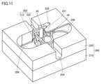
(第2実施形態)
次に、図10及び図11を参照しながら、本発明の第2実施形態のクランプ保持部200について説明する。なお、第2実施形態では、第1実施形態と異なる部分についてのみ説明を行い、第1実施形態と同じ構造、作用及び効果の説明は繰り返さない。 (Second embodiment)
Next, a
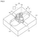
本実施形態では、ケース210は、クランプ30を受けるクランプ受け部212を有している。 In this embodiment, the
カバー220は、前記重なり部221と、前記チューブ収容部204と、前記指回避部206と、保持壁222と、を有する。保持壁222は、クランプ受け部212に受けられたクランプ30の位置を保持する部位である。保持壁222は、クランプ30の周囲に設けられている。保持壁222は、クランプ受け部212とともに前記クランプ収容部202を構成している。 The
この実施形態のカバー220は、重なり部221を有する部位と重なり部221を有しない部位とが連結されている。このため、カバー220の取り扱いが容易になる。 In the
上記各実施形態において、クランプ保持部200は、ポンプ本体100に接続されておらず、ポンプ本体100から独立していてもよい。 In each of the embodiments described above, the
ここで、上記実施形態について概説する。 Here, the above embodiment will be outlined.
上記実施形態のシリンジポンプは、シリンジを駆動する駆動部を有するポンプ本体と、前記シリンジに接続されたチューブ内の流路の開閉を切り替えるクランプであって、前記チューブを保持するベースと、前記ベースに接続されており、前記チューブ内の前記流路が閉塞されるように前記ベースとともに前記チューブを挟持する挟持姿勢と前記流路を開放させる開放姿勢との間で変位可能な挟持片と、を有する前記クランプを保持するクランプ保持部と、を備え、前記クランプ保持部は、前記クランプを収容可能で、かつ、前記ベースに保持された前記チューブの延びる方向と直交する直交方向の一方側に開口する形状を有するクランプ収容部と、前記クランプに保持された前記チューブを収容可能で、かつ、前記クランプ収容部の開口を通じて前記クランプを前記クランプ収容部へ組み付ける組付方向に沿って前記クランプに保持された前記チューブが通過するのを許容するように前記クランプ収容部と同じ側に開口する形状を有するチューブ収容部と、前記組付方向に前記クランプ収容部の一部と重なる重なり部と、を有し、前記重なり部は、前記挟持片が前記挟持姿勢であるときに、前記組付方向に沿った前記クランプ収容部への前記クランプの通過を許容し、かつ、前記挟持片が前記開放姿勢であるときに、前記組付方向に前記クランプの一部と重なることで前記クランプの前記クランプ収容部への組み付けを規制する。 The syringe pump of the above embodiment includes a pump main body having a drive unit that drives a syringe, a clamp that switches opening and closing of a flow path in a tube connected to the syringe, a base that holds the tube, and a base that holds the tube. a clamping piece connected to the tube and movable between a clamping position in which the tube is clamped together with the base so as to close the flow passage in the tube and an open position in which the flow passage is opened; a clamp holding part that holds the clamp, and the clamp holding part is capable of accommodating the clamp and is open on one side in a direction orthogonal to a direction in which the tube held on the base extends. a clamp accommodating part having a shape that is capable of accommodating the tube held by the clamp, and which is held in the clamp along an assembly direction in which the clamp is assembled to the clamp accommodating part through an opening of the clamp accommodating part; a tube accommodating part having a shape that opens on the same side as the clamp accommodating part so as to allow the tube to pass therethrough; and an overlapping part that overlaps a part of the clamp accommodating part in the assembly direction. and the overlapping portion allows passage of the clamp to the clamp accommodating portion along the assembly direction when the clamping piece is in the clamping position, and the overlapped part is configured to allow the clamp to pass through the clamp accommodating part along the assembly direction when the clamping piece is in the open position. When this is the case, the clamp overlaps with a portion of the clamp in the assembly direction, thereby restricting assembly of the clamp to the clamp accommodating portion.
このシリンジポンプでは、クランプが挟持姿勢であるときには、クランプのクランプ収容部への組み付けが許容される一方、クランプが開放姿勢であるときには、クランプの一部が重なり部に干渉することによって当該クランプのクランプ収容部への組み付けが規制されるため、チューブの流路が開放された状態(クランプが開放姿勢である状態)でチューブ及びクランプがクランプ保持部に組み付けられることが抑制される。 In this syringe pump, when the clamp is in the clamping position, the clamp can be assembled into the clamp accommodating part, but when the clamp is in the open position, a part of the clamp interferes with the overlapping part, causing the clamp to Since the assembly to the clamp accommodating part is restricted, the tube and the clamp are prevented from being assembled to the clamp holding part in a state where the flow path of the tube is open (a state in which the clamp is in an open position).
また、前記クランプ保持部は、前記クランプ収容部を有するケースと、前記重なり部を含み、前記ケースに対して着脱可能なカバーと、を有し、前記ケースは、前記クランプ収容部に収容された前記クランプに保持された前記チューブを受ける受け溝を有し、前記カバーは、前記組付方向に沿って前記チューブが通過するのを許容するとともに、前記受け溝とともに前記チューブ収容部を構成するスリットを有していてもよい。 Further, the clamp holding section includes a case having the clamp accommodating section, and a cover that includes the overlapping section and is removable from the case, and the case is accommodated in the clamp accommodating section. The cover has a receiving groove for receiving the tube held by the clamp, and the cover has a slit that allows the tube to pass along the assembly direction and forms the tube accommodating portion together with the receiving groove. It may have.
この態様では、上記の効果が有効に得られる。 In this aspect, the above effects can be effectively obtained.
あるいは、前記クランプ保持部は、前記クランプを受けるクランプ受け部を有するケースと、前記重なり部と前記チューブ収容部とを含み、前記ケースに対して着脱可能なカバーと、を有し、前記カバーは、前記クランプ受け部に受けられた前記クランプの位置を保持する保持壁であって、前記クランプ受け部とともに前記クランプ収容部を構成する前記保持壁を有していてもよい。 Alternatively, the clamp holding section includes a case having a clamp receiving section that receives the clamp, and a cover that includes the overlapping section and the tube accommodating section and is removable from the case, and the cover is , the holding wall may be a holding wall that holds the position of the clamp received in the clamp receiving part, and the holding wall may constitute the clamp accommodating part together with the clamp receiving part.
この態様においても、上記の効果が有効に得られる。 Also in this embodiment, the above effects can be effectively obtained.
また、前記クランプ保持部は、前記挟持姿勢である前記クランプを医療従事者が前記組付方向に沿って前記クランプ収容部に組み付ける際に前記医療従事者の指を回避する指回避部をさらに有することが好ましい。 Further, the clamp holding section further includes a finger avoidance section that avoids the fingers of the medical worker when the medical worker assembles the clamp in the clamping posture to the clamp accommodating section along the assembling direction. It is preferable.
このようにすれば、医療従事者が容易にクランプ収容部にクランプを組付けることが可能となる。 In this way, a medical worker can easily assemble the clamp into the clamp accommodating portion.
また、前記シリンジは、フランジを有するバレルと、前記バレル内から薬液を押し出すことが可能なプランジャと、を有し、前記ポンプ本体は、前記バレルを受けるバレル受け部と、前記プランジャを受けるプランジャ受け部と、前記クランプを前記挟持姿勢と前記開放姿勢とに切り替え可能な切り替え機構と、制御部と、をさらに有し、前記バレル受け部は、前記バレルを検出可能に構成されており、前記プランジャ受け部は、前記プランジャを検出可能に構成されており、前記制御部は、前記バレル受け部による前記バレルの検出及び前記プランジャ受け部による前記プランジャの検出がなされているときに、前記クランプが前記開放姿勢となるように切り替え機構を駆動することが好ましい。 Further, the syringe includes a barrel having a flange and a plunger capable of pushing out a medical solution from inside the barrel, and the pump body includes a barrel receiving portion that receives the barrel and a plunger receiving portion that receives the plunger. , a switching mechanism capable of switching the clamp between the clamping position and the open position, and a control part, the barrel receiving part being configured to be able to detect the barrel, and the barrel receiving part being configured to be able to detect the barrel; The receiving section is configured to be able to detect the plunger, and the control section is configured such that when the barrel receiving section detects the barrel and the plunger receiving section detects the plunger, the clamp detects the plunger. It is preferable to drive the switching mechanism to take the open position.
このようにすれば、バレル及びプランジャがポンプ本体に装着されたことが検出されたときに、クランプが自動的に開放姿勢に切り替えられる。 In this way, when it is detected that the barrel and plunger are attached to the pump body, the clamp is automatically switched to the open position.
なお、今回開示された実施形態はすべての点で例示であって、制限的なものではないと考えられるべきである。本発明の範囲は、上記した実施形態の説明ではなく請求の範囲によって示され、さらに請求の範囲と均等の意味および範囲内でのすべての変更が含まれる。 Note that the embodiments disclosed herein are illustrative in all respects and should not be considered restrictive. The scope of the present invention is indicated by the claims rather than the description of the embodiments described above, and further includes all changes within the meaning and range equivalent to the claims.
10 シリンジ、12 バレル、14 プランジャ、20 チューブ、30 クランプ、31 ベース、32 第1基部、32a 係止部、32h 挿通孔、33 第1挟持突起、36 挟持片、37 第2基部、37a 被係止部、38 第2挟持突起、40 シリンジポンプ、100 ポンプ本体、110 バレル受け部、120 プランジャ受け部、130 駆動部、140 切り替え機構、142 カム、144 モータ、150 制御部、200 クランプ保持部、202 クランプ収容部、204 チューブ収容部、206 指回避部、210 ケース、212 クランプ受け部、214 受け溝、216 指逃げ部、220 カバー、221 重なり部、222 保持壁、224 スリット、226 指逃げ部、228 切り欠き。
Claims (5)
Translated fromJapanese前記シリンジに接続されたチューブ内の流路の開閉を切り替えるクランプであって、前記チューブを保持するベースと、前記ベースに接続されており、前記チューブ内の前記流路が閉塞されるように前記ベースとともに前記チューブを挟持する挟持姿勢と前記流路を開放させる開放姿勢との間で変位可能な挟持片と、を有する前記クランプを保持するクランプ保持部と、を備え、
前記クランプ保持部は、
前記クランプを収容可能で、かつ、前記ベースに保持された前記チューブの延びる方向と直交する直交方向の一方側に開口する形状を有するクランプ収容部と、
前記クランプに保持された前記チューブを収容可能で、かつ、前記クランプ収容部の開口を通じて前記クランプを前記クランプ収容部へ組み付ける組付方向に沿って前記クランプに保持された前記チューブが通過するのを許容するように前記クランプ収容部と同じ側に開口する形状を有するチューブ収容部と、
前記組付方向に前記クランプ収容部の一部と重なる重なり部と、を有し、
前記重なり部は、前記挟持片が前記挟持姿勢であるときに、前記組付方向に沿った前記クランプ収容部への前記クランプの通過を許容し、かつ、前記挟持片が前記開放姿勢であるときに、前記組付方向に前記クランプの一部と重なることで前記クランプの前記クランプ収容部への組み付けを規制する、シリンジポンプ。 a pump body having a drive unit that drives the syringe;
The clamp switches opening and closing of a flow path in a tube connected to the syringe, and includes a base that holds the tube, and a clamp that is connected to the base and configured to close the flow path in the tube. a clamp holding part that holds the clamp and has a holding piece that is movable between a holding position in which the tube is held together with a base and an open position in which the flow path is opened;
The clamp holding part is
a clamp accommodating portion capable of accommodating the clamp and having a shape that opens on one side in a direction perpendicular to an extending direction of the tube held by the base;
The tube held by the clamp can be accommodated, and the tube held by the clamp passes through the opening of the clamp accommodating part along an assembly direction in which the clamp is assembled to the clamp accommodating part. a tube accommodating portion having a shape that opens on the same side as the clamp accommodating portion so as to allow the tube accommodating portion to
an overlapping part that overlaps a part of the clamp accommodating part in the assembly direction,
The overlapping portion allows passage of the clamp to the clamp accommodating portion along the assembly direction when the clamping piece is in the clamping position, and when the clamping piece is in the open position. The syringe pump overlaps a portion of the clamp in the assembly direction to restrict assembly of the clamp to the clamp accommodating portion.
前記クランプ収容部を有するケースと、
前記重なり部を含み、前記ケースに対して着脱可能なカバーと、を有し、
前記ケースは、前記クランプ収容部に収容された前記クランプに保持された前記チューブを受ける受け溝を有し、
前記カバーは、前記組付方向に沿って前記チューブが通過するのを許容するとともに、前記受け溝とともに前記チューブ収容部を構成するスリットを有する、請求項1に記載のシリンジポンプ。 The clamp holding part is
a case having the clamp accommodating part;
a cover that includes the overlapping portion and is removable from the case;
The case has a receiving groove for receiving the tube held by the clamp housed in the clamp housing part,
The syringe pump according to claim 1, wherein the cover has a slit that allows the tube to pass along the assembly direction and forms the tube accommodating portion together with the receiving groove.
前記クランプを受けるクランプ受け部を有するケースと、
前記重なり部と前記チューブ収容部とを含み、前記ケースに対して着脱可能なカバーと、を有し、
前記カバーは、前記クランプ受け部に受けられた前記クランプの位置を保持する保持壁であって、前記クランプ受け部とともに前記クランプ収容部を構成する前記保持壁を有する、請求項1に記載のシリンジポンプ。 The clamp holding part is
a case having a clamp receiving part that receives the clamp;
a cover that includes the overlapping part and the tube accommodating part and is removable from the case;
The syringe according to claim 1, wherein the cover is a holding wall that holds the position of the clamp received in the clamp receiving part, and the holding wall configures the clamp accommodating part together with the clamp receiving part. pump.
薬液を収容可能なバレルと、
前記バレル内から前記薬液を押し出すことが可能なプランジャと、を有し、
前記ポンプ本体は、
前記バレルを受けるバレル受け部と、
前記プランジャを受けるプランジャ受け部と、
前記クランプを前記挟持姿勢と前記開放姿勢とに切り替え可能な切り替え機構と、
制御部と、をさらに有し、
前記バレル受け部は、前記バレルを検出可能に構成されており、
前記プランジャ受け部は、前記プランジャを検出可能に構成されており、
前記制御部は、前記バレル受け部による前記バレルの検出及び前記プランジャ受け部による前記プランジャの検出がなされているときに、前記クランプが前記開放姿勢となるように切り替え機構を駆動する、請求項1から4のいずれかに記載のシリンジポンプ。 The syringe is
A barrel that can contain a chemical solution,
a plunger capable of pushing out the chemical solution from inside the barrel;
The pump body is
a barrel receiving part that receives the barrel;
a plunger receiving portion that receives the plunger;
a switching mechanism capable of switching the clamp between the clamping position and the open position;
further comprising a control unit;
The barrel receiver is configured to be able to detect the barrel,
The plunger receiving portion is configured to be able to detect the plunger,
1 . The control unit drives a switching mechanism so that the clamp assumes the open position when the barrel receiving unit detects the barrel and the plunger receiving unit detects the plunger. The syringe pump according to any one of 4 to 4.
Applications Claiming Priority (3)
| Application Number | Priority Date | Filing Date | Title |
|---|---|---|---|
| JP2019176984 | 2019-09-27 | ||
| JP2019176984 | 2019-09-27 | ||
| PCT/JP2020/035741WO2021060258A1 (en) | 2019-09-27 | 2020-09-23 | Syringe pump |
Publications (2)
| Publication Number | Publication Date |
|---|---|
| JPWO2021060258A1 JPWO2021060258A1 (en) | 2021-04-01 |
| JP7435614B2true JP7435614B2 (en) | 2024-02-21 |
Family
ID=75165815
Family Applications (1)
| Application Number | Title | Priority Date | Filing Date |
|---|---|---|---|
| JP2021548921AActiveJP7435614B2 (en) | 2019-09-27 | 2020-09-23 | syringe pump |
Country Status (2)
| Country | Link |
|---|---|
| JP (1) | JP7435614B2 (en) |
| WO (1) | WO2021060258A1 (en) |
Citations (5)
| Publication number | Priority date | Publication date | Assignee | Title |
|---|---|---|---|---|
| US20050020978A1 (en) | 2001-11-15 | 2005-01-27 | Marc Vollenweider | Safety device for an infusion pump |
| US20140234144A1 (en) | 2011-11-16 | 2014-08-21 | Fresenius Kabi Deutschland Gmbh | Tube pump, tube clamp, perfusion set and system comprising a tube pump and a tube clamp |
| WO2018181810A1 (en) | 2017-03-29 | 2018-10-04 | テルモ株式会社 | Syringe pump |
| JP2019010502A (en) | 2017-06-29 | 2019-01-24 | ニプロ株式会社 | Syringe pump |
| JP2019022609A (en) | 2017-07-24 | 2019-02-14 | テルモ株式会社 | Clamp |
Family Cites Families (1)
| Publication number | Priority date | Publication date | Assignee | Title |
|---|---|---|---|---|
| JP4754917B2 (en)* | 2004-10-19 | 2011-08-24 | テルモ株式会社 | Infusion device |
- 2020
- 2020-09-23WOPCT/JP2020/035741patent/WO2021060258A1/ennot_activeCeased
- 2020-09-23JPJP2021548921Apatent/JP7435614B2/enactiveActive
Patent Citations (5)
| Publication number | Priority date | Publication date | Assignee | Title |
|---|---|---|---|---|
| US20050020978A1 (en) | 2001-11-15 | 2005-01-27 | Marc Vollenweider | Safety device for an infusion pump |
| US20140234144A1 (en) | 2011-11-16 | 2014-08-21 | Fresenius Kabi Deutschland Gmbh | Tube pump, tube clamp, perfusion set and system comprising a tube pump and a tube clamp |
| WO2018181810A1 (en) | 2017-03-29 | 2018-10-04 | テルモ株式会社 | Syringe pump |
| JP2019010502A (en) | 2017-06-29 | 2019-01-24 | ニプロ株式会社 | Syringe pump |
| JP2019022609A (en) | 2017-07-24 | 2019-02-14 | テルモ株式会社 | Clamp |
Also Published As
| Publication number | Publication date |
|---|---|
| JPWO2021060258A1 (en) | 2021-04-01 |
| WO2021060258A1 (en) | 2021-04-01 |
Similar Documents
| Publication | Publication Date | Title |
|---|---|---|
| US11504467B2 (en) | Liquid injection device and assembly including same | |
| EP3448460B1 (en) | Container holder assembly | |
| JP4921779B2 (en) | Indwelling needle | |
| JP6063469B2 (en) | Infusion tube clamp for infusion pump and method of using infusion tube clamp | |
| KR20190057100A (en) | Drug delivery device with cap assembly | |
| JP7435614B2 (en) | syringe pump | |
| JP4767655B2 (en) | Protector and needle set | |
| TWI654006B (en) | Drug container assembly for drug delivery device | |
| CN111683704B (en) | Medicine package assembly | |
| JP5444332B2 (en) | Needle disposal container | |
| CN111699012B (en) | Drug delivery device | |
| JP7089019B2 (en) | Intracutaneous needle and its package and injection device | |
| JP2007089909A (en) | Protector and needle set | |
| JP6644582B2 (en) | Medical pump | |
| US20210244886A1 (en) | Medicament delivery devices | |
| US20090168175A1 (en) | Closing mechanism for lens shutter | |
| JP5200498B2 (en) | Clamp | |
| EP4197573A1 (en) | Winged needle assembly, packaging material for winged needle assembly, cap for winged needle assembly, and winged needle assembly set | |
| JP5200499B2 (en) | Infusion device | |
| JP2007037964A (en) | Syringe pump |
Legal Events
| Date | Code | Title | Description |
|---|---|---|---|
| A621 | Written request for application examination | Free format text:JAPANESE INTERMEDIATE CODE: A621 Effective date:20230623 | |
| TRDD | Decision of grant or rejection written | ||
| A01 | Written decision to grant a patent or to grant a registration (utility model) | Free format text:JAPANESE INTERMEDIATE CODE: A01 Effective date:20240109 | |
| A61 | First payment of annual fees (during grant procedure) | Free format text:JAPANESE INTERMEDIATE CODE: A61 Effective date:20240122 | |
| R150 | Certificate of patent or registration of utility model | Ref document number:7435614 Country of ref document:JP Free format text:JAPANESE INTERMEDIATE CODE: R150 |