JP7435502B2 - module storage housing - Google Patents
module storage housingDownload PDFInfo
- Publication number
- JP7435502B2 JP7435502B2JP2021026185AJP2021026185AJP7435502B2JP 7435502 B2JP7435502 B2JP 7435502B2JP 2021026185 AJP2021026185 AJP 2021026185AJP 2021026185 AJP2021026185 AJP 2021026185AJP 7435502 B2JP7435502 B2JP 7435502B2
- Authority
- JP
- Japan
- Prior art keywords
- module storage
- storage unit
- case
- module
- engagement
- Prior art date
- Legal status (The legal status is an assumption and is not a legal conclusion. Google has not performed a legal analysis and makes no representation as to the accuracy of the status listed.)
- Active
Links
Images


Classifications
- H—ELECTRICITY
- H05—ELECTRIC TECHNIQUES NOT OTHERWISE PROVIDED FOR
- H05K—PRINTED CIRCUITS; CASINGS OR CONSTRUCTIONAL DETAILS OF ELECTRIC APPARATUS; MANUFACTURE OF ASSEMBLAGES OF ELECTRICAL COMPONENTS
- H05K7/00—Constructional details common to different types of electric apparatus
- H05K7/14—Mounting supporting structure in casing or on frame or rack
- H05K7/1401—Mounting supporting structure in casing or on frame or rack comprising clamping or extracting means
- H05K7/1411—Mounting supporting structure in casing or on frame or rack comprising clamping or extracting means for securing or extracting box-type drawers
- H—ELECTRICITY
- H05—ELECTRIC TECHNIQUES NOT OTHERWISE PROVIDED FOR
- H05K—PRINTED CIRCUITS; CASINGS OR CONSTRUCTIONAL DETAILS OF ELECTRIC APPARATUS; MANUFACTURE OF ASSEMBLAGES OF ELECTRICAL COMPONENTS
- H05K5/00—Casings, cabinets or drawers for electric apparatus
- H05K5/02—Details
- H05K5/0256—Details of interchangeable modules or receptacles therefor, e.g. cartridge mechanisms
- H05K5/0286—Receptacles therefor, e.g. card slots, module sockets, card groundings
- H—ELECTRICITY
- H05—ELECTRIC TECHNIQUES NOT OTHERWISE PROVIDED FOR
- H05K—PRINTED CIRCUITS; CASINGS OR CONSTRUCTIONAL DETAILS OF ELECTRIC APPARATUS; MANUFACTURE OF ASSEMBLAGES OF ELECTRICAL COMPONENTS
- H05K7/00—Constructional details common to different types of electric apparatus
- H05K7/14—Mounting supporting structure in casing or on frame or rack
- H05K7/1422—Printed circuit boards receptacles, e.g. stacked structures, electronic circuit modules or box like frames
- H05K7/1427—Housings
- H05K7/1428—Housings for small modular apparatus with terminal block
- Y—GENERAL TAGGING OF NEW TECHNOLOGICAL DEVELOPMENTS; GENERAL TAGGING OF CROSS-SECTIONAL TECHNOLOGIES SPANNING OVER SEVERAL SECTIONS OF THE IPC; TECHNICAL SUBJECTS COVERED BY FORMER USPC CROSS-REFERENCE ART COLLECTIONS [XRACs] AND DIGESTS
- Y02—TECHNOLOGIES OR APPLICATIONS FOR MITIGATION OR ADAPTATION AGAINST CLIMATE CHANGE
- Y02E—REDUCTION OF GREENHOUSE GAS [GHG] EMISSIONS, RELATED TO ENERGY GENERATION, TRANSMISSION OR DISTRIBUTION
- Y02E60/00—Enabling technologies; Technologies with a potential or indirect contribution to GHG emissions mitigation
- Y02E60/10—Energy storage using batteries
Landscapes
- Engineering & Computer Science (AREA)
- Microelectronics & Electronic Packaging (AREA)
- Casings For Electric Apparatus (AREA)
Description
Translated fromJapanese本開示は、モジュールを実装する回路基板を収納したモジュール収納ユニットが挿入された筐体であるモジュール収納筐体に関するものである。 The present disclosure relates to a module storage case, which is a case into which a module storage unit containing a circuit board on which a module is mounted is inserted.
例えばメモリーカード又はSDカードといった通信モジュールを実装する回路基板は、モジュール収納ユニットに収納される。モジュール収納ユニットは、筐体に挿入されて固定される。このとき、モジュール収納ユニットが有するスナップフィット構造である係合爪が、筐体に配置されている溝と係合することで固定されるものが一般的である。 For example, a circuit board on which a communication module such as a memory card or an SD card is mounted is stored in a module storage unit. The module storage unit is inserted into the housing and fixed. At this time, the module storage unit is generally fixed by engaging claws having a snap-fit structure with grooves arranged in the housing.
例えば、従来では、モジュール収納ユニットに相当する電池ホルダに設けられた係合爪と、筐体が有する溝とが係合することで、電池ホルダは固定されていた。そして、モジュール収納ユニットの取り外しには、筐体の側面に設けられた取り外し孔に棒状部材を挿通することで係合を解除していた(例えば、特許文献1参照)。 For example, conventionally, the battery holder was fixed by engagement between an engaging claw provided on the battery holder corresponding to the module storage unit and a groove provided in the housing. To remove the module storage unit, the engagement is released by inserting a rod-shaped member into a removal hole provided on the side surface of the housing (for example, see Patent Document 1).
しかしながら、このような従来のスナップフィット構造を有するモジュール収納ユニットでは、筐体からモジュール収納ユニットを取り外す際に、棒状部材が別途必要であるため、新たに部品点数が増加するという問題点があった。 However, with such a conventional module storage unit having a snap-fit structure, a rod-shaped member is required separately when removing the module storage unit from the housing, which has the problem of increasing the number of new parts. .
本開示は、上記のような問題点を解決するためになされたものであり、部品点数を削減したモジュール収納筐体を得ることを目的としている。 The present disclosure has been made to solve the above-mentioned problems, and aims to provide a module storage case with a reduced number of parts.
本開示に係るモジュール収納筐体は、弾性を有する係合爪が設けられたキャップと係合爪と係合する係合穴が設けられたケースとの間に、モジュールを収納して構成されるモジュール収納ユニットと、カバーおよびカバーが被せられたベースで構成され、ベースにはモジュール収納ユニットを挿入する開口部が設けられている筐体と、を備え、係合穴と係合した係合爪は、係合穴からベースに向かって突出しており、突出した係合爪は、ベースに設けられた係合溝に係合している。 A module storage casing according to the present disclosure is configured by storing a module between a cap provided with an elastic engagement claw and a case provided with an engagement hole that engages with the engagement claw. A housing comprising a module storage unit, a cover and a base covered with the cover, the base having an opening into which the module storage unit is inserted, and an engagement claw that engages with the engagement hole. protrudes from the engagement hole toward the base, and the protruding engagement claw engages with an engagement groove provided in the base.
本開示に係るモジュール収納筐体は、係合穴と係合した係合爪は、係合穴からベースに向かって突出しており、突出した係合爪は、ベースに設けられた係合溝に係合していことで、新たな部品が必要なくモジュール収納ユニットを筐体から挿抜することができ、部品点数を削減することができる。 In the module storage casing according to the present disclosure, the engaging claw that is engaged with the engaging hole projects toward the base from the engaging hole, and the protruding engaging claw is inserted into the engaging groove provided in the base. By being engaged, the module storage unit can be inserted and removed from the housing without the need for new parts, and the number of parts can be reduced.
実施の形態1.
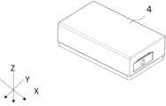
図1は、本実施の形態に係るモジュール収納筐体4の斜視図の例である。モジュール収納筐体4の構造について、順に説明する。
FIG. 1 is an example of a perspective view of a
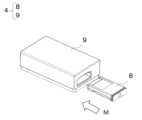
図2は、モジュール収納筐体4からモジュール収納ユニット8を引き出した状態の筐体9とモジュール収納ユニット8を示す斜視図である。つまり、モジュール収納筐体4は、筐体9にモジュール収納ユニット8が挿入され、収容された状態である。図2の矢印Mは、モジュール収納ユニット8を筐体9へ挿入する向きを示している。モジュール収納ユニット8は、図2で示す矢印Mの方向で筐体9に挿入し、図1に示す状態となる。FIG. 2 is a perspective view showing the
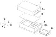
図3は、モジュール収納筐体4の分解斜視図である。図3で示すように、モジュール収納筐体4は、カバー1とベース3の間にプリント配線基板2を挟み込み構成されている。カバー1およびベース3は、例えばガラス繊維強化型のエンジニアリングプラスチック等で形成されている。カバー1は、ベース3を覆うように被せられている。また、カバー1は、モジュール収納ユニット8を挿入するための開口部1aを有している。同様に、ベース3も、モジュール収納ユニット8を挿入するための開口部3aを有している。開口部1a及び開口部3aは、カバー1がベース3を覆った際に互いに重なる位置にある。 FIG. 3 is an exploded perspective view of the
図4は、図3に示す斜視図のベース3をZ方向から見た図である。図4で示すように、ベース3には、係合溝31が設けられている。係合溝31の設け方については、詳しくは後述する。 FIG. 4 is a diagram of the
図5は、モジュール収納ユニット8の斜視図の例である。モジュール収納ユニット8の構造について順に説明する。FIG. 5 is an example of a perspective view of the
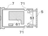
図6は、図5に示すモジュール収納ユニット8の分解斜視図である。図6で示すように、モジュール収納ユニット8は、キャップ5とケース7との間に、モジュール61を実装した回路基板6を収納することで構成されている。キャップ5およびケース7は、ガラス繊維を含有しないPBT(Poly Butylenetereph talate,ポリブチレンテレフタ-ト)又はナイロンといった弾性率の小さい材料で形成されている。また、ケース7とキャップ5が回路基板6を収納した状態において、ケース7は、キャップ5と対向する側に挿抜部72が設けられている。ケース7に設けられた挿抜部72は、取り外し溝73が設けられている。取り外し溝73の設け方については、詳しくは後述する。FIG. 6 is an exploded perspective view of the
図7は、モジュール収納ユニット8を構成しているキャップ5を示す斜視図である。キャップ5には、係合爪51が設けられている。また、各々の係合爪51から延びるように脚部52が設けられている。また、係合爪51は、スナップフィット構造であるため弾性を有しており、先端は角を丸めたR形状である。FIG. 7 is a perspective view showing the
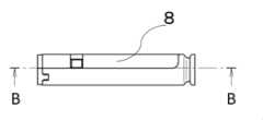
図8は、図1に示す斜視図のZ方向からみたモジュール収納筐体4の断面図である。ベース3内に収納されたモジュール収納ユニット8は、キャップ5の係合爪51が係合溝31に係合して固定されている。係合されている様子については、詳細は後述する。 FIG. 8 is a sectional view of the
図9は、モジュール収納筐体4からモジュール収納ユニット8を挿抜する途中の様子を示しており、図1に示す斜視図のZ方向からみたモジュール収納筐体4の断面図である。モジュール収納ユニット8は、ベース3が有する係合溝31にキャップ5が近くなる向きで、挿抜される。 FIG. 9 shows the
図10は、モジュール収納ユニット8の側面図である。図11は、ケース7とキャップ5が取り付けられた状態のモジュール収納ユニット8の図10の矢印B-B断面図である。図12は、ケース7へキャップ5が取り付けられている途中の状態を示す図10の矢印B―B断面図である。 FIG. 10 is a side view of the
図10~図12で示すように、キャップ5の係合爪51は、ケース7の側壁によって、モジュール61がある内側へ押し込まれた弾性変形した状態となる。 As shown in FIGS. 10 to 12, the engaging
回路基板6は、キャップ5の係合爪51がケース7の係合穴71に係合することでモジュール収納ユニット8内に収納される。キャップ5とケース7が係合された係合爪51は、係合穴71を通ってケース7の側壁より突出した状態となる。 The
続いて、キャップ5が有する係合爪51および係合穴71と、筐体9が有する係合溝31との係合している様子について説明する。 Next, a description will be given of how the engaging
図13は、図8で示すAの部分の拡大図である。図13を用いて、係合爪51が係合穴71と係合した状態の係合爪51の各部の説明をする。 FIG. 13 is an enlarged view of part A shown in FIG. 8. Each part of the
図13に示すように、モジュール収納ユニット8が筐体9に収納されると、係合爪51は、ケース7が有する係合穴71と係合する。さらに、係合穴71と係合した係合爪51は、係合穴71を通ってベース3側に突出し、ベース3が有する係合溝31と係合する。 As shown in FIG. 13, when the
図13に示すように、係合爪51は、固定面51aおよび傾斜面51bで構成されている。固定面51aは、脚部52に続いて設けられている。固定面51aは、係合穴71の側面に面している。固定面51aとモジュール収納ユニット8を筐体9に挿入する向きとがなす角度は、90度以下である。傾斜面51bは、固定面51aに続いて開口部に向かって設けられている。傾斜面51bとモジュール収納ユニット8を筐体9に挿入する向きとがなす角度は、90度未満である。As shown in FIG. 13, the engaging
係合爪51が、係合穴71および係合溝31と係合している状態では、モジュール収納ユニット8は筐体9から外れない。図9に示すように、作業者がモジュール収納ユニット8をある一定の負荷で筐体9から引き出した際に、係合爪51は弾性変形し、係合溝31との係合が外れるため、筐体9からモジュール収納ユニット8を取り出すことが可能となる。 In a state where the
図14は、ケース7の斜視図である。挿抜部72は、モジュール収納ユニット8を筐体9内に収容した状態で、ベース3の開口部3aおよびカバー1の開口部1aの位置に合わせたケース7上に設けられている。また、挿抜部72の全周には、開口部3aおよび開口部1aに沿うように取り外し溝73が設けられている。作業者は、取り外し溝73を掴んで、筐体9からモジュール収納ユニット8を取り外す。 FIG. 14 is a perspective view of the
モジュール収納筐体4を備えた遮断器等の機器の部品が、モジュール収納筐体4に隣接して配置されている場合、取り外し溝73が一部のみにしか設けられていなければ、作業者が取り外し溝73を掴むことが困難となり、筐体9からモジュール収納ユニット8を取り外すことが難しい可能性がある。したがって、モジュール収納筐体4を共用化する際に、モジュール収納ユニット8の挿抜方向が限定され、機器の設計自由度が低下する恐れがある。 When a component of a device such as a circuit breaker equipped with the
しかし、取り外し溝73が挿抜部72の全周にあることで、モジュール収納筐体4を共用化する際、モジュール収納ユニット8の収納方向は限定されないため、機器の設計の自由度を向上させることができる。However, since the
本実施の形態によれば、追加部品なく筐体9からモジュール収納ユニット8を取り外すことが可能となり、部品点数が削減される。また、部品点数の削減に伴い、コストを抑制することができる。また、モジュール収納ユニット8を取り外す際に新たに部品が必要ないため、筐体9内に取り外す際に用いる部品を入れるためのスペースを削減することができる。 According to this embodiment, the
また、キャップ5の係合爪51は弾性を有しているため、作業者は、モジュール収納ユニット8の筐体9への取り付け時にクリック感が得られる。クリック感により、作業者は取り付けが完了したことを容易に判断することができる。 Moreover, since the engaging
また、ケース7の挿抜部72の全周に取り外し溝73を設けることで、モジュール収納ユニット8の取り付け方向が限定されず、モジュール収納筐体4の共用化が容易となり、機器の設計の自由度を向上できる。 Furthermore, by providing the
1 カバー
2 プリント配線基板
3 ベース
31 係合溝
4 モジュール収納筐体
5 キャップ
51 係合爪
51a 固定面
51b 傾斜面
52 脚部
6 回路基板
61 モジュール
7 ケース
71 係合穴
72 挿抜部
73 取り外し溝
8 モジュール収納ユニット
9 筐体 1
Claims (3)
Translated fromJapaneseカバーおよび前記カバーが被せられたベースで構成され、前記ベースには前記モジュール収納ユニットを挿入する開口部が設けられている筐体と、
を備え、
前記係合穴と係合した前記係合爪は、前記係合穴から前記ベースに向かって突出しており、突出した前記係合爪は、前記ベースに設けられた係合溝に係合している
モジュール収納筐体。 A module storage unit configured to store a module between a cap provided with an elastic engagement claw and a case provided with an engagement hole that engages with the engagement claw;
a casing comprising a cover and a base covered with the cover, the base having an opening into which the module storage unit is inserted;
Equipped with
The engaging claw that engaged with the engaging hole projects from the engaging hole toward the base, and the protruding engaging claw engages with an engaging groove provided in the base. Module storage case.
前記係合穴と係合した前記係合爪は、前記脚部に続いて設けられた固定面および前記固定面に続いて前記開口部に向かって設けられた傾斜面で構成されており、前記固定面と前記モジュール収納ユニットを前記筐体に挿入する向きとがなす角度は90度以下であり、前記傾斜面と前記挿入する向きとがなす角度は90度未満である
請求項1に記載のモジュール収納筐体。 The cap is provided with legs extending from the engagement claw,
The engagement claw engaged with the engagement hole includes a fixing surface provided following the leg portion and an inclined surface provided following the fixing surface toward the opening, and The angle between the fixing surface and the direction in which the module storage unit is inserted into the housing is 90 degrees or less, and the angle between the inclined surface and the direction in which the module is inserted is less than 90 degrees. Module storage case.
前記開口部の位置に合わせて設けられた挿抜部および前記開口部に沿うように前記挿抜部の全周に取り外し溝が設けられている
請求項1又は2に記載のモジュール収納筐体。 In the above case,
The module storage case according to claim 1 or 2, further comprising an insertion/extraction part provided in accordance with the position of the opening, and a removal groove provided around the entire circumference of the insertion/extraction part along the opening.
Priority Applications (2)
| Application Number | Priority Date | Filing Date | Title |
|---|---|---|---|
| JP2021026185AJP7435502B2 (en) | 2021-02-22 | 2021-02-22 | module storage housing |
| CN202210145183.0ACN114980635A (en) | 2021-02-22 | 2022-02-17 | Module housing frame |
Applications Claiming Priority (1)
| Application Number | Priority Date | Filing Date | Title |
|---|---|---|---|
| JP2021026185AJP7435502B2 (en) | 2021-02-22 | 2021-02-22 | module storage housing |
Publications (2)
| Publication Number | Publication Date |
|---|---|
| JP2022127936A JP2022127936A (en) | 2022-09-01 |
| JP7435502B2true JP7435502B2 (en) | 2024-02-21 |
Family
ID=82976139
Family Applications (1)
| Application Number | Title | Priority Date | Filing Date |
|---|---|---|---|
| JP2021026185AActiveJP7435502B2 (en) | 2021-02-22 | 2021-02-22 | module storage housing |
Country Status (2)
| Country | Link |
|---|---|
| JP (1) | JP7435502B2 (en) |
| CN (1) | CN114980635A (en) |
Citations (3)
| Publication number | Priority date | Publication date | Assignee | Title |
|---|---|---|---|---|
| US20080165508A1 (en) | 2007-01-05 | 2008-07-10 | Apple Inc. | Ejectable component assemblies in electronic devices |
| JP2008305869A (en) | 2007-06-05 | 2008-12-18 | Fujitsu Ten Ltd | Accommodation case |
| JP2014182920A (en) | 2013-03-19 | 2014-09-29 | Yamaichi Electronics Co Ltd | Tray type card connector |
Family Cites Families (3)
| Publication number | Priority date | Publication date | Assignee | Title |
|---|---|---|---|---|
| JPH0442048U (en)* | 1990-08-07 | 1992-04-09 | ||
| JPH0743948Y2 (en)* | 1992-07-23 | 1995-10-09 | 任天堂株式会社 | Battery mounting structure |
| JPH1031307A (en)* | 1996-07-12 | 1998-02-03 | Konica Corp | Photosensitive composition, photosensitive lithographic printing plate and method for developing the same |
- 2021
- 2021-02-22JPJP2021026185Apatent/JP7435502B2/enactiveActive
- 2022
- 2022-02-17CNCN202210145183.0Apatent/CN114980635A/enactivePending
Patent Citations (3)
| Publication number | Priority date | Publication date | Assignee | Title |
|---|---|---|---|---|
| US20080165508A1 (en) | 2007-01-05 | 2008-07-10 | Apple Inc. | Ejectable component assemblies in electronic devices |
| JP2008305869A (en) | 2007-06-05 | 2008-12-18 | Fujitsu Ten Ltd | Accommodation case |
| JP2014182920A (en) | 2013-03-19 | 2014-09-29 | Yamaichi Electronics Co Ltd | Tray type card connector |
Also Published As
| Publication number | Publication date |
|---|---|
| CN114980635A (en) | 2022-08-30 |
| JP2022127936A (en) | 2022-09-01 |
Similar Documents
| Publication | Publication Date | Title |
|---|---|---|
| JP4391488B2 (en) | Game machine | |
| US20070047359A1 (en) | Flash memory device | |
| US8047859B2 (en) | USB plug protective cover | |
| JP5634361B2 (en) | Electrical equipment | |
| JP2007063921A (en) | Portable machine and mechanical key | |
| JP7435502B2 (en) | module storage housing | |
| CN106463931A (en) | Receiving section and electrical junction box with same | |
| JP5821470B2 (en) | Game machine | |
| EP2282487A1 (en) | Assembly for housing a memory card in an electronic device | |
| JP6035722B2 (en) | Game machine | |
| JP3678697B2 (en) | Mobile terminal device | |
| JP2007191917A (en) | Door handle device | |
| JP5346530B2 (en) | Holding frame for connector module | |
| JP4312042B2 (en) | Cable tie fixing structure | |
| JPH01169416A (en) | optical transmission module | |
| JP5971696B2 (en) | Electronic device casing and electronic device decorative panel | |
| US20030027445A1 (en) | Portective cove for pin interconnect | |
| JP4918410B2 (en) | Connector with protector | |
| JP4084259B2 (en) | Electrical junction box | |
| JP3239328B2 (en) | Waterproof connector | |
| JP2008123794A (en) | Connector push-in protector | |
| KR102701540B1 (en) | IC card reader module for card terminals with a cassette type or cartridge type structure | |
| CN222184420U (en) | Key storage components, manual-automatic switching modules and fire protection products | |
| JP4298618B2 (en) | Electronic device housing structure | |
| JP3125532U (en) | Memory card adapter with terminal protection slide cover |
Legal Events
| Date | Code | Title | Description |
|---|---|---|---|
| RD01 | Notification of change of attorney | Free format text:JAPANESE INTERMEDIATE CODE: A7421 Effective date:20220427 | |
| A621 | Written request for application examination | Free format text:JAPANESE INTERMEDIATE CODE: A621 Effective date:20230413 | |
| TRDD | Decision of grant or rejection written | ||
| A977 | Report on retrieval | Free format text:JAPANESE INTERMEDIATE CODE: A971007 Effective date:20231227 | |
| A01 | Written decision to grant a patent or to grant a registration (utility model) | Free format text:JAPANESE INTERMEDIATE CODE: A01 Effective date:20240109 | |
| A61 | First payment of annual fees (during grant procedure) | Free format text:JAPANESE INTERMEDIATE CODE: A61 Effective date:20240122 | |
| R151 | Written notification of patent or utility model registration | Ref document number:7435502 Country of ref document:JP Free format text:JAPANESE INTERMEDIATE CODE: R151 |