JP7434730B2 - Vehicle information display device and vehicle control device - Google Patents
Vehicle information display device and vehicle control deviceDownload PDFInfo
- Publication number
- JP7434730B2 JP7434730B2JP2019111102AJP2019111102AJP7434730B2JP 7434730 B2JP7434730 B2JP 7434730B2JP 2019111102 AJP2019111102 AJP 2019111102AJP 2019111102 AJP2019111102 AJP 2019111102AJP 7434730 B2JP7434730 B2JP 7434730B2
- Authority
- JP
- Japan
- Prior art keywords
- vehicle
- output
- unit
- display device
- image
- Prior art date
- Legal status (The legal status is an assumption and is not a legal conclusion. Google has not performed a legal analysis and makes no representation as to the accuracy of the status listed.)
- Active
Links
Images


Classifications
- G—PHYSICS
- G06—COMPUTING OR CALCULATING; COUNTING
- G06V—IMAGE OR VIDEO RECOGNITION OR UNDERSTANDING
- G06V10/00—Arrangements for image or video recognition or understanding
- G06V10/96—Management of image or video recognition tasks
- B—PERFORMING OPERATIONS; TRANSPORTING
- B60—VEHICLES IN GENERAL
- B60R—VEHICLES, VEHICLE FITTINGS, OR VEHICLE PARTS, NOT OTHERWISE PROVIDED FOR
- B60R1/00—Optical viewing arrangements; Real-time viewing arrangements for drivers or passengers using optical image capturing systems, e.g. cameras or video systems specially adapted for use in or on vehicles
- B60R1/20—Real-time viewing arrangements for drivers or passengers using optical image capturing systems, e.g. cameras or video systems specially adapted for use in or on vehicles
- B60R1/22—Real-time viewing arrangements for drivers or passengers using optical image capturing systems, e.g. cameras or video systems specially adapted for use in or on vehicles for viewing an area outside the vehicle, e.g. the exterior of the vehicle
- B60R1/28—Real-time viewing arrangements for drivers or passengers using optical image capturing systems, e.g. cameras or video systems specially adapted for use in or on vehicles for viewing an area outside the vehicle, e.g. the exterior of the vehicle with an adjustable field of view
- G—PHYSICS
- G06—COMPUTING OR CALCULATING; COUNTING
- G06V—IMAGE OR VIDEO RECOGNITION OR UNDERSTANDING
- G06V20/00—Scenes; Scene-specific elements
- G06V20/50—Context or environment of the image
- G06V20/56—Context or environment of the image exterior to a vehicle by using sensors mounted on the vehicle
- G06V20/58—Recognition of moving objects or obstacles, e.g. vehicles or pedestrians; Recognition of traffic objects, e.g. traffic signs, traffic lights or roads
- G—PHYSICS
- G08—SIGNALLING
- G08G—TRAFFIC CONTROL SYSTEMS
- G08G1/00—Traffic control systems for road vehicles
- G08G1/16—Anti-collision systems
- G08G1/168—Driving aids for parking, e.g. acoustic or visual feedback on parking space
- H—ELECTRICITY
- H04—ELECTRIC COMMUNICATION TECHNIQUE
- H04N—PICTORIAL COMMUNICATION, e.g. TELEVISION
- H04N5/00—Details of television systems
- H04N5/222—Studio circuitry; Studio devices; Studio equipment
- H04N5/262—Studio circuits, e.g. for mixing, switching-over, change of character of image, other special effects ; Cameras specially adapted for the electronic generation of special effects
- H04N5/268—Signal distribution or switching
- H—ELECTRICITY
- H04—ELECTRIC COMMUNICATION TECHNIQUE
- H04N—PICTORIAL COMMUNICATION, e.g. TELEVISION
- H04N7/00—Television systems
- H04N7/18—Closed-circuit television [CCTV] systems, i.e. systems in which the video signal is not broadcast
- H04N7/183—Closed-circuit television [CCTV] systems, i.e. systems in which the video signal is not broadcast for receiving images from a single remote source
- H—ELECTRICITY
- H04—ELECTRIC COMMUNICATION TECHNIQUE
- H04N—PICTORIAL COMMUNICATION, e.g. TELEVISION
- H04N7/00—Television systems
- H04N7/18—Closed-circuit television [CCTV] systems, i.e. systems in which the video signal is not broadcast
- H04N7/188—Capturing isolated or intermittent images triggered by the occurrence of a predetermined event, e.g. an object reaching a predetermined position
- B—PERFORMING OPERATIONS; TRANSPORTING
- B60—VEHICLES IN GENERAL
- B60R—VEHICLES, VEHICLE FITTINGS, OR VEHICLE PARTS, NOT OTHERWISE PROVIDED FOR
- B60R2300/00—Details of viewing arrangements using cameras and displays, specially adapted for use in a vehicle
- B60R2300/10—Details of viewing arrangements using cameras and displays, specially adapted for use in a vehicle characterised by the type of camera system used
- B60R2300/105—Details of viewing arrangements using cameras and displays, specially adapted for use in a vehicle characterised by the type of camera system used using multiple cameras
- B—PERFORMING OPERATIONS; TRANSPORTING
- B60—VEHICLES IN GENERAL
- B60R—VEHICLES, VEHICLE FITTINGS, OR VEHICLE PARTS, NOT OTHERWISE PROVIDED FOR
- B60R2300/00—Details of viewing arrangements using cameras and displays, specially adapted for use in a vehicle
- B60R2300/20—Details of viewing arrangements using cameras and displays, specially adapted for use in a vehicle characterised by the type of display used
- B—PERFORMING OPERATIONS; TRANSPORTING
- B60—VEHICLES IN GENERAL
- B60R—VEHICLES, VEHICLE FITTINGS, OR VEHICLE PARTS, NOT OTHERWISE PROVIDED FOR
- B60R2300/00—Details of viewing arrangements using cameras and displays, specially adapted for use in a vehicle
- B60R2300/30—Details of viewing arrangements using cameras and displays, specially adapted for use in a vehicle characterised by the type of image processing
- B—PERFORMING OPERATIONS; TRANSPORTING
- B60—VEHICLES IN GENERAL
- B60R—VEHICLES, VEHICLE FITTINGS, OR VEHICLE PARTS, NOT OTHERWISE PROVIDED FOR
- B60R2300/00—Details of viewing arrangements using cameras and displays, specially adapted for use in a vehicle
- B60R2300/70—Details of viewing arrangements using cameras and displays, specially adapted for use in a vehicle characterised by an event-triggered choice to display a specific image among a selection of captured images
- B—PERFORMING OPERATIONS; TRANSPORTING
- B60—VEHICLES IN GENERAL
- B60R—VEHICLES, VEHICLE FITTINGS, OR VEHICLE PARTS, NOT OTHERWISE PROVIDED FOR
- B60R2300/00—Details of viewing arrangements using cameras and displays, specially adapted for use in a vehicle
- B60R2300/80—Details of viewing arrangements using cameras and displays, specially adapted for use in a vehicle characterised by the intended use of the viewing arrangement
- B60R2300/806—Details of viewing arrangements using cameras and displays, specially adapted for use in a vehicle characterised by the intended use of the viewing arrangement for aiding parking
- G—PHYSICS
- G06—COMPUTING OR CALCULATING; COUNTING
- G06V—IMAGE OR VIDEO RECOGNITION OR UNDERSTANDING
- G06V20/00—Scenes; Scene-specific elements
- G06V20/50—Context or environment of the image
- G06V20/59—Context or environment of the image inside of a vehicle, e.g. relating to seat occupancy, driver state or inner lighting conditions
- G06V20/597—Recognising the driver's state or behaviour, e.g. attention or drowsiness
- H—ELECTRICITY
- H04—ELECTRIC COMMUNICATION TECHNIQUE
- H04N—PICTORIAL COMMUNICATION, e.g. TELEVISION
- H04N23/00—Cameras or camera modules comprising electronic image sensors; Control thereof
- H04N23/90—Arrangement of cameras or camera modules, e.g. multiple cameras in TV studios or sports stadiums
Landscapes
- Engineering & Computer Science (AREA)
- Multimedia (AREA)
- Signal Processing (AREA)
- Physics & Mathematics (AREA)
- General Physics & Mathematics (AREA)
- Mechanical Engineering (AREA)
- Theoretical Computer Science (AREA)
- Closed-Circuit Television Systems (AREA)
- Traffic Control Systems (AREA)
Description
Translated fromJapaneseここに開示された技術は、車両に用いられる情報表示装置、制御装置に関する技術分野に属する。 The technology disclosed herein belongs to the technical field related to information display devices and control devices used in vehicles.
近年、車両には、多数の運転支援機器が搭載されており、暗電流が増大している。この暗電流を抑制するために、車両の各機器の電源を不使用時に遮断するのが望ましい。一方で、各機器の起動時間は、極力短縮することが望まれる。 In recent years, vehicles have been equipped with a large number of driving support devices, resulting in an increase in dark current. In order to suppress this dark current, it is desirable to shut off the power to each device in the vehicle when not in use. On the other hand, it is desirable to shorten the startup time of each device as much as possible.
特許文献1には、車両が駐車したときに、出発時に車載表示装置の起動時間を短縮する技術が開示されている。具体的に、特許文献1の技術では、出発時に後退発進する必要があるときに、ユーザーの電源オフ操作時に揮発性メモリバックアップ手段によるバックアップを実行する。
特許文献1の技術は、車両が駐車して出発する際の起動時間に関する技術であるが、車両の出発時以外にも起動時間の短縮が望まれている機能がある。例えば、駐車場に入って後退発進させる前に、リアビューカメラを起動させる構成を有する車両があるが、このリアビューカメラの起動時間を所定時間以内に短縮する要求があり、専用のソフトウェアやハードウェアを用いて起動時間の短縮がされている。しかしながら、専用のソフトウェアやハードウェアを使用すると、設計に手間がかかり、コストが増加する。 The technology of
ここに開示された技術は、斯かる点に鑑みてなされたものであり、運転中の車両が後方発進する場合にカメラの撮像画像を早期に表示させることにある。 The technology disclosed herein has been developed in view of this point, and its purpose is to display an image captured by a camera at an early stage when a vehicle being driven starts backwards.
前記課題を解決するために、ここに開示された技術の一態様では、表示画面に車外環境を撮像するカメラの撮像画像を表示できるように構成された車両用情報表示装置を対象として、車両内部または車両外部の少なくとも一方の環境情報を取得する環境情報取得部からの出力を基に、後退発進の発生を予測する環境判定部と、前記カメラからの撮像信号を受信して前記表示画面に表示する画像を生成する画像処理部とを備え、前記環境判定部で後退発進の発生が予測された場合、あらかじめ前記後退発進のための前記画像処理部での処理を開始し、ユーザーが後退発進操作をしたときに、前記表示画面に前記画像処理部の出力画像を表示させる、という構成とした。 In order to solve the above problems, one aspect of the technology disclosed herein targets a vehicle information display device that is configured to display an image captured by a camera that captures an environment outside the vehicle on a display screen. or an environment determination unit that predicts the occurrence of a backward start based on an output from an environment information acquisition unit that acquires environmental information of at least one of the outside of the vehicle; and an environment determination unit that receives an image signal from the camera and displays it on the display screen. and an image processing unit that generates an image for reversing, and when the environment determining unit predicts the occurrence of a reverse start, the image processing unit starts processing for the reverse start in advance, and the user performs a reverse start operation. The display screen is configured to display an output image of the image processing unit on the display screen when
この構成によると、後退発進の発生が予測された場合に、あらかじめ後退発進のための画像処理部の処理を開始するので、ユーザーが後退発進操作をしたときに、表示画面に画像処理部の出力画像を早期に表示させることができる。また、処理の高速化をするために機能を特化したハードウェアやソフトウェアを使用する必要がないので、コストの増加を防ぐことができる。 According to this configuration, when the occurrence of a reverse start is predicted, the image processing unit starts processing for the reverse start in advance, so when the user performs a reverse start operation, the image processing unit outputs the output on the display screen. Images can be displayed early. Furthermore, since there is no need to use hardware or software with specialized functions to speed up processing, an increase in costs can be prevented.
前記外部環境認識装置において、前記環境情報取得部は、前記カメラを含み、走行シーンに対応した前記環境情報取得部の設定パラメータを記憶する記憶部を有し、前記環境情報取得部からの出力及びユーザーの後退発進操作を基に、前記設定パラメータを後退発進用のパラメータに切り替える、という構成でもよい。 In the external environment recognition device, the environment information acquisition unit includes the camera and has a storage unit that stores setting parameters of the environment information acquisition unit corresponding to a driving scene, and the environment information acquisition unit includes an output from the environment information acquisition unit and a storage unit that stores setting parameters of the environment information acquisition unit corresponding to a driving scene. The configuration may be such that the setting parameters are switched to parameters for starting in reverse based on the user's operation to start in reverse.
この構成によると、設定パラメータを後退発進用のパラメータに変更することができるので、検出精度を向上させることができる。ここで、設定パラメータには、ダイナミックレンジ、カメラの輝度、カメラの分解能等のパラメータが含まれる。 According to this configuration, the setting parameters can be changed to parameters for starting in reverse, so detection accuracy can be improved. Here, the setting parameters include parameters such as dynamic range, camera brightness, and camera resolution.
ここに開示された技術の他の一態様では、車両用制御装置を対象として、車両内部または車両外部の少なくとも一方の環境情報を取得する環境情報取得部からの出力を基に、車両の特定の動作の発生を予測する環境判定部を備え、前記環境判定部で前記特定の動作の発生が予測された場合に、前記特定の動作に対応して動作させるデバイスの設定パラメータをあらかじめ準備し、ユーザーが特定の動作を指示する操作を行ったときに、前記デバイスに設定パラメータを反映させる制御部とを備えている、という構成でもよい。 In another aspect of the technology disclosed herein, a vehicle control device is used to acquire specific information about a vehicle based on an output from an environmental information acquisition unit that acquires environmental information of at least one of the interior of the vehicle and the exterior of the vehicle. an environment determining unit that predicts the occurrence of an action; when the environment determining unit predicts the occurrence of the specific action, setting parameters for a device to be operated in accordance with the specific action are prepared in advance; The configuration may also include a control unit that causes setting parameters to be reflected in the device when the device performs an operation that instructs a specific operation.
ここで、本明細書中でいう「デバイス」とは、自動車が走行する際に制御されるアクチュエータやセンサ等の装置類を含む。 Here, the term "device" as used herein includes devices such as actuators and sensors that are controlled when the vehicle is running.
この構成によると、特定の動作に対応して動作させるデバイスの設定パラメータをあらかじめ準備しているので、ユーザーが特定の動作を指示する操作を行ったときに、早期に設定パラメータを反映させてデバイスを動作させることができる。 According to this configuration, the setting parameters of the device to be operated in response to a specific action are prepared in advance, so when the user performs an operation to instruct a specific action, the setting parameters are reflected at an early stage and the device is activated. can be operated.
以上説明したように、ここに開示された技術によると、後退発進の発生が予測された場合に、あらかじめ後退発進のための画像処理部の処理を開始するので、ユーザーが後退発進操作をしたときに、表示画面に画像処理部の出力画像を早期に表示させることができる。 As explained above, according to the technology disclosed herein, when the occurrence of a reverse start is predicted, the image processing unit starts processing for a reverse start in advance, so when the user performs a reverse start operation In addition, the output image of the image processing section can be displayed on the display screen at an early stage.
以下、例示的な実施形態について、図面を参照しながら詳細に説明する。 Hereinafter, exemplary embodiments will be described in detail with reference to the drawings.
<第1実施形態>
図1は、本実施形態に係る車両用情報表示装置の構成を概略的に示すブロック図である。なお、図1では、本実施形態の情報表示装置としての機能を発揮するための構成を示しており、車両の情報表示に関わるすべての機能を示しているわけではない。 <First embodiment>
FIG. 1 is a block diagram schematically showing the configuration of a vehicle information display device according to this embodiment. Note that FIG. 1 shows the configuration for performing the function of the information display device of this embodiment, and does not show all the functions related to information display of the vehicle.
車両1は、車両1の動作を制御する演算装置を備えている。演算装置は、1つ又は複数のチップで構成されたマイクロプロセッサであって、CPUやメモリ等を有している。例えば、演算装置は、以下で説明する車両用情報表示装置100の機能を実現するための構成を含む。 The
車両用情報表示装置100は、車内に設けられた画像表示装置40の表示画面41に、カーナビゲーションシステムの経路案内情報や道路交通情報、後退発進時のリアビューカメラの画像情報等を表示させるインフォテイメントシステム120を備える。以下の説明では、説明の便宜上、画像表示装置40の表示画面41に表示させる情報を総称して、単に「表示情報」という。 The vehicle
インフォテイメントシステム120は、カメラ21の撮像画像のうちリアモニタ用の画像処理をする画像処理部121と、車外通信部30に受信した外部情報の表示処理をする機能を有するIVI(In-vehicle infotainment)処理部122と、画像処理部121またはIVI処理部122のうちの一方の出力を選択して画像表示装置40に出力するセレクタ123とを備えている。 The
センサデバイス20は、(1)車両1のボディ等に設けられかつ車外環境を撮影する複数のカメラ21と、(2)車両1のボディ等に設けられかつ車外の物標等を検知する複数のレーダ22と、(3)全地球測位システム(Global Positioning System:GPS)を利用して、車両1の位置(車両位置情報)を検出する位置センサ23と、(4)車速センサ、加速度センサ、ヨーレートセンサ等の車両の挙動を検出するセンサ類の出力から構成され車両1の状態を取得する車両状態センサ24と、(5)車内カメラ等により構成され、車両1の乗員の状態を取得する乗員状態センサ25と、(6)運転者の運転操作を検出するための運転操作情報取得部26とを含む。運転操作情報取得部26は、アクセル開度センサ、シフトレバーの位置を検出するシフトセンサ、ブレーキセンサ及び操舵角センサを含む。運転操作情報取得部26は、シフトセンサの出力を基に、出力切替信号SC2を出力する。出力切替信号SC2の信号形式は特に限定されない。本実施形態では、運転操作情報取得部26は、運転者がシフトレバーを「Rレンジ」に入れた場合に「High」を出力し、運転者がシフトレバーを「Rレンジ」以外に入れた場合に「Low」を出力するものとして説明する。 The
カメラ21は、車両外前方を撮像するフロントビューカメラ21a、車両外側方を撮像するサイドビューカメラ21b及び駐車時に車両外後方を撮像する駐車用のリアビューカメラ21cを含む。駐車用のリアビューカメラ21cは、駐車時に使用するカメラであり、本実施形態では、一般道や高速道路を走行している場合のような、いわゆる、通常運転中には、消費電力を抑制するために、起動していない状態であるとする。なお、カメラ21が、駐車用のリアビューカメラ21c以外に、通常運転時に動作し、後方を監視するためのリアビューカメラを備えていてもよい。 The
車外通信部30は、車外のネットワークと接続されている。車外通信部30には、自車両の周囲に位置する他車両からの通信情報やナビゲーションシステムからの交通情報が入力される。以下において、説明の便宜上、車外通信部30を介して外部ネットワークから受けた情報を総称して「外部情報」という。センサデバイス20及び車外通信部30は、環境情報取得部の一例である。 The
画像処理部121は、一般道や高速道路を走行している場合のようなとき、いわゆる、通常運転時には、消費電力を抑制するために、起動していない状態である。例えば、画像処理部121は、環境判定部115から車両1の後退発進の発生が予測されることを示す予測信号SC1を受信した場合に起動される。画像処理部121は、駐車用のリアビューカメラ21cの撮像信号を受信し、画像表示装置40の表示画面41に表示するための画像を生成し、出力する。 The
環境判定部115は、車外環境を認識する車外環境認識部111からの車外環境情報、車両挙動推定部113からの車両挙動推定情報、及び、乗員挙動推定部114からの乗員挙動推定情報を受信し、車両の走行シーンや外部環境、車内環境、乗員の状態等を含む車両が置かれている状況(以下、車両状況という)を判定する。特に、本実施形態では、環境判定部115は、車両状況として、車両1に後退発進が発生することを予測する。例えば、環境判定部115は、少しの時間が経過した後に、すなわち、近い将来に車両1が後退発進する可能性がある状況になったことを判定する。後退発進の予測判定方法は、特に限定されないが、例えば、環境判定部115は、車外環境情報を基に、車両1が駐車場に進入した場合に、後退発進の可能性があると判定する。また、例えば、環境判定部115は、車外環境情報、車両挙動推定情報及び乗員挙動推定情報を基に、車両1がスピードを落としながら路肩に近づき、一旦停車後に、乗員が後ろを見たことを検知した場合に、後退発進の可能性があると判定する。 The
IVI処理部122は、車内のカーナビゲーション装置から地図情報を受信したり、車外通信部30を介して外部のネットワークから外部情報として経路案内情報や道路交通情報、地上波放送等のエンターテイメント情報を受信したりする。そして、乗員の設定情報やリモコン等の操作情報に基づいて、乗員の希望に合致するコンテンツを表示させるためのコンテンツ情報を出力する。なお、ここでは、IVI処理部122のうち、本実施形態に係る機能を発揮するための構成や機能を例示しており、IVI処理部122が有する全ての構成や機能を示しているわけではない。 The
セレクタ123は、画像処理部121で生成されたリアビューカメラ21cの撮像画像と、IVI処理部122から出力されたコンテンツ情報とを受信する。そして、セレクタ123は、運転操作情報取得部26からの出力切替信号SC2に基づいて、リアビューカメラ21cの撮像画像と、IVI処理部122から出力されたコンテンツ情報のいずれか一方を出力する。具体的に、運転者がシフトレバーを「Rレンジ」に入れていない場合にはIVI処理部122の出力を選択し、運転者がシフトレバーをRレンジに入れた場合には画像処理部121の出力を選択して、画像表示装置40に出力する。画像表示装置40の表示画面41には、セレクタ123で選択された情報が表示される。 The
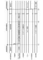
図2は、図1の車両用情報表示装置の動作を示すタイミングチャートである。図2において、車両1は、一般道を通常走行した後に、時刻t10において駐車場に入り、時間t30において運転者がシフトレバーを「Rレンジ」に移動させ、その後、車両1を後退発進させたものとする。なお、予測信号SC1は、ハイアクティブであるものとする。 FIG. 2 is a timing chart showing the operation of the vehicle information display device shown in FIG. In FIG. 2, after driving normally on a general road,
図2の時刻t10より前の時間は、車両1は、通常走行をしており、画像表示装置40には、カーナビゲーションの画像のように、IVI処理部122から出力されたコンテンツ情報が表示されている。 During the time before time t10 in FIG. 2, the
図2の時刻t10において、車両1が駐車場に入ると、車外環境認識部111において車両1が駐車場に入ったことが認識され、認識結果が環境判定部115に送信される。 When the
車両1が駐車場に入ったことが認識されると、環境判定部115は、車外環境認識部111の認識結果を基に、予測信号SC1を「High」にする。そうすると、リアビューカメラ21c及び画像処理部121が起動される。そうすると、リアビューカメラ21cにおいて、起動処理及び画像処理部121が実行される。 When it is recognized that the
例えば、リアビューカメラ21cが起動された後、マイコン等の各種部品にリセット処理が行われて撮像が開始される。その後、リアビューカメラ21cにおいて、歪み除去・輝度調整等を行い、リアビューカメラ21cから撮像信号が出力される。画像処理部121では、リアビューカメラ21cと同様に、ソフトウェア及びハードウェアのリセット処理が行われる(図2の時刻t10~t20参照)。そして、画像処理の準備が整った状態で、リアビューカメラ21cから撮像信号が出力されると、リアビューカメラ21cの撮像画像が順次セレクタ123に出力される(図2の時刻t20参照)。時刻t10~t20の間の時間は、演算装置10の処理速度や、リアビューカメラ21cの起動時間等によって異なるが、専用回路を使用せずに、汎用の電子部品で起動回路等を構成した場合、概ね数秒程度の時間を要する。ここで、時刻t20が経過した後も、車両が駐車スペースを探している場合、すなわち、シフトレバーが「Dレンジ」に入っている間は、IVI処理部122から出力されたコンテンツ情報が継続して表示される。 For example, after the rear view camera 21c is activated, reset processing is performed on various components such as a microcomputer, and imaging is started. Thereafter, distortion removal, brightness adjustment, etc. are performed in the rear view camera 21c, and an imaging signal is output from the rear view camera 21c. In the
時刻t30において、運転者が駐車する場所を決定し、シフトレバーを「Rレンジ」に入れると、運転操作情報取得部26の出力切替信号SC2が「Low」から「High」に切り替わる。そうすると、セレクタ123の出力信号が、IVI処理部122の出力信号から、リアビューカメラ21cの撮像画像に切り替えられる。 At time t30, when the driver decides where to park and puts the shift lever into the "R range", the output switching signal SC2 of the driving operation
以上をまとめると、本実施形態の車両用情報表示装置100は、車両1の内部または車両1の外部の少なくとも一方の環境情報を取得するセンサデバイス20からの出力を基に、後退発進の発生を予測する環境判定部115と、カメラ21からの撮像信号を受信して画像表示装置40の表示画面41に表示する画像を生成する画像処理部121とを備える。そして、環境判定部115で後退発進の発生が予測された場合、あらかじめ後退発進のためのカメラの起動や画像処理部121の処理を開始し、ユーザーが後退発進操作をしたときに、表示画面に画像処理部121の出力画像を表示させるようにしている。 To summarize the above, the vehicle
このように、環境判定部115で後退発進の発生が予測された場合に、あらかじめカメラの起動や画像処理部121の処理を開始している。換言すると、表示画面に画像処理部121の出力画像を表示させるための準備をあらかじめ行っている。これにより、ユーザーが後退発進操作をしたときに、出力画像を早期に表示させることができる。これにより、ユーザーが後退発進操作をしてからカメラの起動や画像処理部121の処理を開始する場合と比較して、表示画面41に画像を表示させるまでの時間を大幅に短縮させることができる。また、カメラの起動や画像処理部121の処理を開始するまでの十分な時間を確保することができるので、カメラの早期立ち上げに特化したハードウエア/ソフトウェアの使用が不要となり、コストが増加することを防ぐことができる。 In this manner, when the
なお、上記の実施形態では、リアビューカメラ21cは起動していない状態であるとしたが、これに限定されない。例えば、駐車用のリアビューカメラ21cを走行時の後方監視用のカメラと兼用しているような場合には、リアビューカメラ21cは通常走行時も起動状態となっている。この場合においても、本開示の技術は適用することができる。具体的には、後方監視用のカメラとしての設定と、駐車用のリアビューカメラとしての設定は、画角の広さや、精度を高める撮像距離等の設定が異なる場合がある。その場合に、上記実施形態のように、環境判定部115で後退発進の発生が予測された場合に、後方監視用のカメラとしての設定から、駐車用のリアビューカメラとしての設定に変更するようにするとよい。環境判定部115で後退発進の発生が予測される場合には、車両のスピードも遅くなっていることが想定される。したがって、あらかじめカメラの設定変更を行っても、その影響は軽微なものであり、例えば、他のセンサ(例えば、レーダ)の結果を用いたりすることで、カメラの設定変更の影響を受けないようにすることも可能である。 Note that in the above embodiment, the rear view camera 21c is not activated, but the present invention is not limited to this. For example, if the rear view camera 21c for parking is also used as a rear view camera while driving, the rear view camera 21c is activated even during normal driving. Even in this case, the technology of the present disclosure can be applied. Specifically, the setting as a rear monitoring camera and the setting as a parking rear view camera may have different settings such as the width of the angle of view and the imaging distance to improve accuracy. In this case, as in the above embodiment, when the
なお、仮に、後退発進の発生が予測された後に、後退発進が行われずに、車両1が通常走行状態に戻った場合、リアビューカメラ21cが通常走行時の状態に戻されるようにしてもよい。具体的には、例えば、リアビューカメラ21cは、起動されていない状態に戻される。 Note that, if the
<第2実施形態>
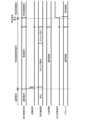
図3は、本実施形態に係る車両用制御装置130の構成を概略的に示すブロック図である。なお、図3において、図1と共通の構成要素には、共通の符号を付してその説明を省略する場合がある。図3において、センサデバイス20及び車外通信部30の構成、並びに、車外環境認識部111、車両挙動推定部113、乗員挙動推定部114及び環境判定部115の構成は、図1と同様であり、ここではその詳細説明を省略する。 <Second embodiment>
FIG. 3 is a block diagram schematically showing the configuration of the
図3では、車両用制御装置130は、車外環境認識部111、車両挙動推定部113及び乗員挙動推定部114の出力を受信し、コントロールユニット50のパラメータを設定するパラメータ設定部132と、コントロールユニット50のパラメータを変更するための変更パラメータを設定する変更パラメータ設定部131とを備えている。さらに、車両用制御装置130は、パラメータ設定部132及びパラメータ設定部131の出力を受けて、いずれか一方を選択して出力する2つのセレクタ133,134を備えている。セレクタ133は、環境判定部115から出力される出力切替信号に基づいて、前述のパラメータまたは変更パラメータの一方を選択してセンサデバイス20に出力する。同様に、セレクタ134は、環境判定部115から出力される出力切替信号に基づいて、前述のパラメータまたは変更パラメータの一方を選択してコントロールユニット50に出力する。ここで、コントロールユニット50とは、自動車が走行する際に制御されるアクチュエータやセンサ等の装置類を制御するためのユニットであり、特に、車両1の駆動、制動、操舵に関わるアクチュエータを制御する機能を有する。すなわち、セレクタ134は、アクチュエータやセンサ等の装置類を制御するためのパラメータを出力する。なお、上記の出力切替信号が、センサデバイス20及び車外通信部30の少なくとも一方から出力されるようにしてもよい。 In FIG. 3, the
ここで、変更パラメータ設定部131は、第1の実施形態の画像処理部121の場合と同様に、環境判定部115からの出力に基づいて、センサデバイス20やコントロールユニット50の設定を変更するための変更パラメータを準備する。 Here, the change
例えば、環境判定部115において、車両状態センサ24の出力結果から、車両が十分に低速で走行していることが判定された場合に、変更パラメータ設定部131では、データベースDB等にあらかじめ保存された設定情報等に基づいて、あらかじめ変更パラメータを準備する。例えば、アクセル感度を通常速度で走行している状態よりも下げるような変更パラメータを準備する。アクセル感度を通常速度で走行している状態よりも下げることで、運転者がアクセル操作の微調整ができるようになる。そして、運転者が特定の動作や操作をした場合に、センサデバイス20から出力切替信号が出力され、変更パラメータが反映される。また、例えば、上記のアクセル感度を調整する場合に、運転者が「特定の動作」の前提となる所定の予備的な動作をした場合に、環境判定部が、「特定の動作」の発生が予測されると判断し、変更パラメータを準備する。そして、実際に、運転者が実際に「特定の動作」をした場合に、セレクタ133,134が切り替えられて、デバイスに設定パラメータが反映されるとしてもよい。 For example, when the
以上をまとめると、本実施形態の車両用制御装置130は、車両内部または車両外部の少なくとも一方の環境情報を取得するセンサデバイス20からの出力を基に、車両の特定の動作の発生を予測する環境判定部115を備え、環境判定部115で特定の動作の発生が予測された場合に、特定の動作に対応して動作させるデバイスの設定パラメータをあらかじめ準備し、ユーザーが特定の動作を指示する操作を行ったときに、コントロールユニット50に設定パラメータを反映させるようにした。 To summarize the above, the
このように、特定の動作に対応して動作させるデバイスの設定パラメータをあらかじめ準備しているので、ユーザーが特定の動作を指示する操作を行ったときに、早期にコントロールユニット50に設定パラメータを反映させることができる。 In this way, since the setting parameters of the device to be operated in response to a specific action are prepared in advance, when the user performs an operation to instruct a specific action, the setting parameters are reflected in the
なお、上記設定パラメータとして、例えば、走行シーンに依存してエンジンの動かす気筒数を変更するようにしてもよい。また、設定パラメータは、デバイスの設定パラメータに限定されず、例えば、走行シーンを踏まえた上で、自動運転システムで作成する車外環境マップの大きさや分解能といった演算処理等のためのパラメータを変更するようにしてもよい。 Note that, as the setting parameter, for example, the number of cylinders operated by the engine may be changed depending on the driving scene. In addition, the setting parameters are not limited to device setting parameters, but may include, for example, changing parameters for calculation processing such as the size and resolution of the external environment map created by the automatic driving system based on the driving scene. You may also do so.
また、車両用制御装置130が、車両内部または車両外部の少なくとも一方の環境情報を取得するセンサデバイス20からの出力を基に、車両の特定の動作の発生を予測する環境判定部115を備え、環境判定部115での判定結果を使って、ユーザーが特定の動作を指示する操作を前提とせずに、その環境に適したパラメータを設定するようにしてもよい。 In addition, the
ここに開示された技術は、自律移動体の外部環境を認識する外部環境認識装置として有用である。 The technology disclosed herein is useful as an external environment recognition device that recognizes the external environment of an autonomous mobile body.
100 車両用情報表示装置
115 環境判定部
121 画像処理部
130 車両用制御装置100 Vehicle
Claims (3)
Translated fromJapanese前記リアビューカメラで撮像された画像データを受信し、当該画像データに所定の画像処理をする画像処理部と、
シフトレバーの位置を検出する運転操作情報部の出力に応じて車内に設けられたモニタ画面の表示を切り替える表示切替部と、
車両外前方を撮像するフロントビューカメラの出力、車速センサの出力、及び、運転者を撮像する車内カメラの出力に基づいて、車両の後退発進を予測する環境判定部とを備え、
前記運転操作情報部でシフトレバーがリバース位置以外にあることが検出されている場合において、前記環境判定部において車両の後退発進が予測された場合、前記リアビューカメラを停止状態から起動状態にし、かつ、前記画像処理部が、当該起動状態になった前記リアビューカメラから受信された画像データの前記所定の画像処理を開始して、前記画像処理部から前記表示切替部に前記リアビューカメラの撮像画像が出力される状態にしておき、
前記表示切替部は、前記運転操作情報部からシフトレバーのリバース位置への移動を示す移動信号を受信したときに、車内に設けられたモニタ画面の表示を、前記画像処理部の出力画像に切り替える
車両用情報表示装置。 A vehicle information display device that displays an image captured by a rear view camera that captures an image of the rear outside the vehicle on a display screen of an image display device inside the vehicle,
an image processing unit that receives image data captured by the rear view camera and performs predetermined image processing on the image data;
a display switching unit that switches a display on a monitor screen provided in the vehicle according to an output from a driving operation information unit that detects the position of the shift lever;
an environment determination unit that predicts a backward start of the vehicle based on the output of a front view camera that images the outside of the vehicle in front, the output of the vehicle speed sensor, and the output of the in-vehicle camera that images the driver;
When the driving operation information unit detects that the shift lever is in a position other than the reverse position, and the environment determination unit predicts that the vehicle will start in reverse, the rear view camera is changed from a stopped state to an activated state, and , the image processing section starts the predetermined image processing of the image data received from the rear view camera in the activated state, and the captured image of the rear view camera is transmitted from the image processing section to the display switching section. Leave it in a state where it will be output,
The display switching unit switches the display on a monitor screen provided in the vehicle to the output image of the image processing unit when receiving a movement signal indicating movement of the shift lever to the reverse position from the driving operation information unit. Vehicle information display device.
前記環境判定部は、前記フロントビューカメラを含む車外環境を認識する車外環境認識部の出力に基づいて、車両の駐車場への進入が認識されることをもって車両の後退発進が予測されるとする、
ことを特徴とする車両用情報表示装置。 The vehicle information display device according to claim 1,
The environment determination unit assumes that the vehicle is predicted to start in reverse when the vehicle enters the parking lot, based on the output of the vehicle exterior environment recognition unit that recognizes the vehicle exterior environment including the front view camera. ,
A vehicle information display device characterized by:
前記環境判定部は、前記車速センサの出力に基づいて車両の一時停車を認識し、かつ、当該車両の一時停車の後に、前記車内カメラで運転者の後方視認動作が認識されることをもって車両の後退発進が予測されるとする、
ことを特徴とする車両用情報表示装置。
The vehicle information display device according to claim 1 or 2,
The environment determination unit recognizes a temporary stop of the vehicle based on the output of the vehicle speed sensor, and determines whether the vehicle is in a state where the driver's rearward visual movement is recognized by the in-vehicle camera after the vehicle has stopped temporarily. Assuming that a backward start is predicted,
A vehicle information display device characterized by:
Priority Applications (5)
| Application Number | Priority Date | Filing Date | Title |
|---|---|---|---|
| JP2019111102AJP7434730B2 (en) | 2019-06-14 | 2019-06-14 | Vehicle information display device and vehicle control device |
| PCT/JP2020/011406WO2020250525A1 (en) | 2019-06-14 | 2020-03-16 | On-vehicle information display device |
| US17/610,698US11794655B2 (en) | 2019-06-14 | 2020-03-16 | On-vehicle information display device |
| CN202080031692.XACN113727884A (en) | 2019-06-14 | 2020-03-16 | Vehicle information display device |
| EP20823360.1AEP3939835B1 (en) | 2019-06-14 | 2020-03-16 | On-vehicle information display device |
Applications Claiming Priority (1)
| Application Number | Priority Date | Filing Date | Title |
|---|---|---|---|
| JP2019111102AJP7434730B2 (en) | 2019-06-14 | 2019-06-14 | Vehicle information display device and vehicle control device |
Publications (2)
| Publication Number | Publication Date |
|---|---|
| JP2020203524A JP2020203524A (en) | 2020-12-24 |
| JP7434730B2true JP7434730B2 (en) | 2024-02-21 |
Family
ID=73781768
Family Applications (1)
| Application Number | Title | Priority Date | Filing Date |
|---|---|---|---|
| JP2019111102AActiveJP7434730B2 (en) | 2019-06-14 | 2019-06-14 | Vehicle information display device and vehicle control device |
Country Status (5)
| Country | Link |
|---|---|
| US (1) | US11794655B2 (en) |
| EP (1) | EP3939835B1 (en) |
| JP (1) | JP7434730B2 (en) |
| CN (1) | CN113727884A (en) |
| WO (1) | WO2020250525A1 (en) |
Families Citing this family (6)
| Publication number | Priority date | Publication date | Assignee | Title |
|---|---|---|---|---|
| JP7556289B2 (en)* | 2020-12-25 | 2024-09-26 | トヨタ自動車株式会社 | Information processing device, information processing method, program, and information processing system |
| US11952080B2 (en)* | 2022-06-16 | 2024-04-09 | Tien Hsin Industries Co., Ltd. | Bicycle derailleur system |
| JP2024031523A (en)* | 2022-08-26 | 2024-03-07 | トヨタ自動車株式会社 | Vehicle surroundings monitoring system, vehicle, image processing device, and vehicle surroundings monitoring method |
| US20240239265A1 (en)* | 2023-01-17 | 2024-07-18 | Rivian Ip Holdings, Llc | Rear display enhancements |
| CN116198476A (en)* | 2023-04-28 | 2023-06-02 | 盛瑞传动股份有限公司 | Fault prompting method and device, electronic equipment, storage medium and vehicle |
| KR20250100316A (en)* | 2023-12-26 | 2025-07-03 | (주)현보 | An apparatus and method for controlling switching of front camera and rear camera mounted on a vehicle |
Citations (10)
| Publication number | Priority date | Publication date | Assignee | Title |
|---|---|---|---|---|
| JP2000207696A (en) | 1999-01-18 | 2000-07-28 | Sharp Corp | In-vehicle camera device |
| JP2007249103A (en) | 2006-03-20 | 2007-09-27 | Zenrin Co Ltd | Road image creation system, road image creation method, and road image composition apparatus |
| JP2008024230A (en) | 2006-07-24 | 2008-02-07 | Toyota Motor Corp | Vehicle control device |
| JP2009078746A (en) | 2007-09-27 | 2009-04-16 | Sanyo Electric Co Ltd | On-vehicle camera system |
| JP2009206354A (en) | 2008-02-28 | 2009-09-10 | Fuji Mach Mfg Co Ltd | Image recognition apparatus and image recognition method of electronic component mounting machine |
| JP2009205191A (en) | 2008-02-26 | 2009-09-10 | Hitachi Ltd | Parking space recognition system |
| JP2010059820A (en) | 2008-09-02 | 2010-03-18 | Toyota Motor Corp | Drive force controller |
| JP2011025895A (en) | 2009-07-29 | 2011-02-10 | Hitachi Automotive Systems Ltd | Parking support device |
| JP2011182254A (en) | 2010-03-02 | 2011-09-15 | Suzuki Motor Corp | Driving support device for vehicle |
| JP2018155079A (en) | 2017-03-21 | 2018-10-04 | 日立建機株式会社 | Work machine |
Family Cites Families (13)
| Publication number | Priority date | Publication date | Assignee | Title |
|---|---|---|---|---|
| JPH10244891A (en)* | 1997-03-07 | 1998-09-14 | Nissan Motor Co Ltd | Parking assistance device |
| JP2005184395A (en)* | 2003-12-18 | 2005-07-07 | Sumitomo Electric Ind Ltd | Image processing method, image processing system, image processing apparatus, and photographing apparatus |
| US8130269B2 (en)* | 2005-03-23 | 2012-03-06 | Aisin Aw Co., Ltd. | Visual recognition apparatus, methods, and programs for vehicles |
| JP2010195168A (en) | 2009-02-25 | 2010-09-09 | Alpine Electronics Inc | Rear camera photographed image display control device |
| JP4927904B2 (en)* | 2009-05-07 | 2012-05-09 | 富士通テン株式会社 | Vehicle driving support device |
| KR20120060108A (en)* | 2010-12-01 | 2012-06-11 | 현대자동차주식회사 | ISG System and Control Method thereof |
| JP5277272B2 (en)* | 2011-03-04 | 2013-08-28 | 株式会社ホンダアクセス | Vehicle rear monitoring device |
| JP5803627B2 (en) | 2011-12-05 | 2015-11-04 | 株式会社デンソー | In-vehicle display device |
| JP2016164010A (en)* | 2015-03-06 | 2016-09-08 | 株式会社富士通ゼネラル | In-vehicle camera system |
| EP3176035A1 (en) | 2015-12-03 | 2017-06-07 | Fico Mirrors S.A. | A rear vision system for a motor vehicle |
| US20170246991A1 (en)* | 2016-02-25 | 2017-08-31 | M.I.S. Electronics Inc. | Multi-function automotive camera |
| EP3876516B1 (en)* | 2018-10-31 | 2025-01-22 | Sony Group Corporation | Photographing device, image processing method, and program |
| JP7215228B2 (en)* | 2019-03-01 | 2023-01-31 | トヨタ自動車株式会社 | Control device, control method, control program |
- 2019
- 2019-06-14JPJP2019111102Apatent/JP7434730B2/enactiveActive
- 2020
- 2020-03-16CNCN202080031692.XApatent/CN113727884A/enactivePending
- 2020-03-16EPEP20823360.1Apatent/EP3939835B1/enactiveActive
- 2020-03-16USUS17/610,698patent/US11794655B2/enactiveActive
- 2020-03-16WOPCT/JP2020/011406patent/WO2020250525A1/ennot_activeCeased
Patent Citations (10)
| Publication number | Priority date | Publication date | Assignee | Title |
|---|---|---|---|---|
| JP2000207696A (en) | 1999-01-18 | 2000-07-28 | Sharp Corp | In-vehicle camera device |
| JP2007249103A (en) | 2006-03-20 | 2007-09-27 | Zenrin Co Ltd | Road image creation system, road image creation method, and road image composition apparatus |
| JP2008024230A (en) | 2006-07-24 | 2008-02-07 | Toyota Motor Corp | Vehicle control device |
| JP2009078746A (en) | 2007-09-27 | 2009-04-16 | Sanyo Electric Co Ltd | On-vehicle camera system |
| JP2009205191A (en) | 2008-02-26 | 2009-09-10 | Hitachi Ltd | Parking space recognition system |
| JP2009206354A (en) | 2008-02-28 | 2009-09-10 | Fuji Mach Mfg Co Ltd | Image recognition apparatus and image recognition method of electronic component mounting machine |
| JP2010059820A (en) | 2008-09-02 | 2010-03-18 | Toyota Motor Corp | Drive force controller |
| JP2011025895A (en) | 2009-07-29 | 2011-02-10 | Hitachi Automotive Systems Ltd | Parking support device |
| JP2011182254A (en) | 2010-03-02 | 2011-09-15 | Suzuki Motor Corp | Driving support device for vehicle |
| JP2018155079A (en) | 2017-03-21 | 2018-10-04 | 日立建機株式会社 | Work machine |
Also Published As
| Publication number | Publication date |
|---|---|
| WO2020250525A1 (en) | 2020-12-17 |
| CN113727884A (en) | 2021-11-30 |
| JP2020203524A (en) | 2020-12-24 |
| EP3939835B1 (en) | 2023-12-13 |
| EP3939835A1 (en) | 2022-01-19 |
| US11794655B2 (en) | 2023-10-24 |
| EP3939835A4 (en) | 2022-07-13 |
| US20220242316A1 (en) | 2022-08-04 |
Similar Documents
| Publication | Publication Date | Title |
|---|---|---|
| JP7434730B2 (en) | Vehicle information display device and vehicle control device | |
| EP3745361B1 (en) | Vehicle recording control device, vehicle recording device, vehicle recording control method, and program | |
| US11731637B2 (en) | Driver assistance system | |
| JP4978558B2 (en) | Vehicle display device | |
| US12115975B2 (en) | Parking support system and control method thereof | |
| EP3742724B1 (en) | Vehicle recording control device, vehicle recording device, vehicle recording control method, and program | |
| JP2024026539A (en) | Control device, method and program | |
| KR20190046579A (en) | Multiple camera control system and method for controlling output of multiple camera image | |
| JP2013109505A (en) | Periphery monitoring device | |
| JP2003312415A (en) | Pre-presentation device for vehicles | |
| JP2024169579A (en) | Vehicle display control device, method, program, and vehicle display system | |
| US20180148045A1 (en) | Driver assistance system having controller and controlling method thereof | |
| US11052822B2 (en) | Vehicle control apparatus, control method, and storage medium for storing program | |
| JP2006168509A (en) | Automatic traveling controller | |
| JP2016164010A (en) | In-vehicle camera system | |
| JP7116670B2 (en) | TRIP CONTROL DEVICE, CONTROL METHOD AND PROGRAM | |
| JP7501146B2 (en) | Vehicle recording device and recording control method | |
| US20160335891A1 (en) | Vehicle speed limit display device | |
| JP4535264B2 (en) | Nose view monitor device | |
| JP2010000843A (en) | Periphery display device | |
| JP7746912B2 (en) | Image display control system | |
| JP2009214800A (en) | Running control device for vehicle | |
| JPH09159468A (en) | Travel position display device | |
| JP2022154051A (en) | Anomaly detection device for in-vehicle camera sensor | |
| JP2023119850A (en) | Storage system and storage control device |
Legal Events
| Date | Code | Title | Description |
|---|---|---|---|
| A621 | Written request for application examination | Free format text:JAPANESE INTERMEDIATE CODE: A621 Effective date:20220517 | |
| A131 | Notification of reasons for refusal | Free format text:JAPANESE INTERMEDIATE CODE: A131 Effective date:20230509 | |
| A521 | Request for written amendment filed | Free format text:JAPANESE INTERMEDIATE CODE: A523 Effective date:20230707 | |
| A131 | Notification of reasons for refusal | Free format text:JAPANESE INTERMEDIATE CODE: A131 Effective date:20230912 | |
| A521 | Request for written amendment filed | Free format text:JAPANESE INTERMEDIATE CODE: A523 Effective date:20231106 | |
| TRDD | Decision of grant or rejection written | ||
| A01 | Written decision to grant a patent or to grant a registration (utility model) | Free format text:JAPANESE INTERMEDIATE CODE: A01 Effective date:20240109 | |
| A61 | First payment of annual fees (during grant procedure) | Free format text:JAPANESE INTERMEDIATE CODE: A61 Effective date:20240122 | |
| R150 | Certificate of patent or registration of utility model | Ref document number:7434730 Country of ref document:JP Free format text:JAPANESE INTERMEDIATE CODE: R150 |