JP7434392B2 - Delivery system for radially deflating the stent graft - Google Patents
Delivery system for radially deflating the stent graftDownload PDFInfo
- Publication number
- JP7434392B2 JP7434392B2JP2022039207AJP2022039207AJP7434392B2JP 7434392 B2JP7434392 B2JP 7434392B2JP 2022039207 AJP2022039207 AJP 2022039207AJP 2022039207 AJP2022039207 AJP 2022039207AJP 7434392 B2JP7434392 B2JP 7434392B2
- Authority
- JP
- Japan
- Prior art keywords
- stent
- graft
- wire
- delivery system
- stent graft
- Prior art date
- Legal status (The legal status is an assumption and is not a legal conclusion. Google has not performed a legal analysis and makes no representation as to the accuracy of the status listed.)
- Active
Links
Images


Classifications
- A—HUMAN NECESSITIES
- A61—MEDICAL OR VETERINARY SCIENCE; HYGIENE
- A61F—FILTERS IMPLANTABLE INTO BLOOD VESSELS; PROSTHESES; DEVICES PROVIDING PATENCY TO, OR PREVENTING COLLAPSING OF, TUBULAR STRUCTURES OF THE BODY, e.g. STENTS; ORTHOPAEDIC, NURSING OR CONTRACEPTIVE DEVICES; FOMENTATION; TREATMENT OR PROTECTION OF EYES OR EARS; BANDAGES, DRESSINGS OR ABSORBENT PADS; FIRST-AID KITS
- A61F2/00—Filters implantable into blood vessels; Prostheses, i.e. artificial substitutes or replacements for parts of the body; Appliances for connecting them with the body; Devices providing patency to, or preventing collapsing of, tubular structures of the body, e.g. stents
- A61F2/95—Instruments specially adapted for placement or removal of stents or stent-grafts
- A61F2/962—Instruments specially adapted for placement or removal of stents or stent-grafts having an outer sleeve
- A61F2/966—Instruments specially adapted for placement or removal of stents or stent-grafts having an outer sleeve with relative longitudinal movement between outer sleeve and prosthesis, e.g. using a push rod
- A61F2/9662—Instruments specially adapted for placement or removal of stents or stent-grafts having an outer sleeve with relative longitudinal movement between outer sleeve and prosthesis, e.g. using a push rod the middle portion of the stent or stent-graft is released first
- A—HUMAN NECESSITIES
- A61—MEDICAL OR VETERINARY SCIENCE; HYGIENE
- A61F—FILTERS IMPLANTABLE INTO BLOOD VESSELS; PROSTHESES; DEVICES PROVIDING PATENCY TO, OR PREVENTING COLLAPSING OF, TUBULAR STRUCTURES OF THE BODY, e.g. STENTS; ORTHOPAEDIC, NURSING OR CONTRACEPTIVE DEVICES; FOMENTATION; TREATMENT OR PROTECTION OF EYES OR EARS; BANDAGES, DRESSINGS OR ABSORBENT PADS; FIRST-AID KITS
- A61F2/00—Filters implantable into blood vessels; Prostheses, i.e. artificial substitutes or replacements for parts of the body; Appliances for connecting them with the body; Devices providing patency to, or preventing collapsing of, tubular structures of the body, e.g. stents
- A61F2/02—Prostheses implantable into the body
- A61F2/04—Hollow or tubular parts of organs, e.g. bladders, tracheae, bronchi or bile ducts
- A61F2/06—Blood vessels
- A61F2/07—Stent-grafts
- A—HUMAN NECESSITIES
- A61—MEDICAL OR VETERINARY SCIENCE; HYGIENE
- A61F—FILTERS IMPLANTABLE INTO BLOOD VESSELS; PROSTHESES; DEVICES PROVIDING PATENCY TO, OR PREVENTING COLLAPSING OF, TUBULAR STRUCTURES OF THE BODY, e.g. STENTS; ORTHOPAEDIC, NURSING OR CONTRACEPTIVE DEVICES; FOMENTATION; TREATMENT OR PROTECTION OF EYES OR EARS; BANDAGES, DRESSINGS OR ABSORBENT PADS; FIRST-AID KITS
- A61F2/00—Filters implantable into blood vessels; Prostheses, i.e. artificial substitutes or replacements for parts of the body; Appliances for connecting them with the body; Devices providing patency to, or preventing collapsing of, tubular structures of the body, e.g. stents
- A61F2/95—Instruments specially adapted for placement or removal of stents or stent-grafts
- A61F2/954—Instruments specially adapted for placement or removal of stents or stent-grafts for placing stents or stent-grafts in a bifurcation
- A—HUMAN NECESSITIES
- A61—MEDICAL OR VETERINARY SCIENCE; HYGIENE
- A61F—FILTERS IMPLANTABLE INTO BLOOD VESSELS; PROSTHESES; DEVICES PROVIDING PATENCY TO, OR PREVENTING COLLAPSING OF, TUBULAR STRUCTURES OF THE BODY, e.g. STENTS; ORTHOPAEDIC, NURSING OR CONTRACEPTIVE DEVICES; FOMENTATION; TREATMENT OR PROTECTION OF EYES OR EARS; BANDAGES, DRESSINGS OR ABSORBENT PADS; FIRST-AID KITS
- A61F2/00—Filters implantable into blood vessels; Prostheses, i.e. artificial substitutes or replacements for parts of the body; Appliances for connecting them with the body; Devices providing patency to, or preventing collapsing of, tubular structures of the body, e.g. stents
- A61F2/95—Instruments specially adapted for placement or removal of stents or stent-grafts
- A61F2/9517—Instruments specially adapted for placement or removal of stents or stent-grafts handle assemblies therefor
- A—HUMAN NECESSITIES
- A61—MEDICAL OR VETERINARY SCIENCE; HYGIENE
- A61F—FILTERS IMPLANTABLE INTO BLOOD VESSELS; PROSTHESES; DEVICES PROVIDING PATENCY TO, OR PREVENTING COLLAPSING OF, TUBULAR STRUCTURES OF THE BODY, e.g. STENTS; ORTHOPAEDIC, NURSING OR CONTRACEPTIVE DEVICES; FOMENTATION; TREATMENT OR PROTECTION OF EYES OR EARS; BANDAGES, DRESSINGS OR ABSORBENT PADS; FIRST-AID KITS
- A61F2/00—Filters implantable into blood vessels; Prostheses, i.e. artificial substitutes or replacements for parts of the body; Appliances for connecting them with the body; Devices providing patency to, or preventing collapsing of, tubular structures of the body, e.g. stents
- A61F2/95—Instruments specially adapted for placement or removal of stents or stent-grafts
- A61F2002/9505—Instruments specially adapted for placement or removal of stents or stent-grafts having retaining means other than an outer sleeve, e.g. male-female connector between stent and instrument
- A61F2002/9511—Instruments specially adapted for placement or removal of stents or stent-grafts having retaining means other than an outer sleeve, e.g. male-female connector between stent and instrument the retaining means being filaments or wires
- A—HUMAN NECESSITIES
- A61—MEDICAL OR VETERINARY SCIENCE; HYGIENE
- A61F—FILTERS IMPLANTABLE INTO BLOOD VESSELS; PROSTHESES; DEVICES PROVIDING PATENCY TO, OR PREVENTING COLLAPSING OF, TUBULAR STRUCTURES OF THE BODY, e.g. STENTS; ORTHOPAEDIC, NURSING OR CONTRACEPTIVE DEVICES; FOMENTATION; TREATMENT OR PROTECTION OF EYES OR EARS; BANDAGES, DRESSINGS OR ABSORBENT PADS; FIRST-AID KITS
- A61F2/00—Filters implantable into blood vessels; Prostheses, i.e. artificial substitutes or replacements for parts of the body; Appliances for connecting them with the body; Devices providing patency to, or preventing collapsing of, tubular structures of the body, e.g. stents
- A61F2/95—Instruments specially adapted for placement or removal of stents or stent-grafts
- A61F2/962—Instruments specially adapted for placement or removal of stents or stent-grafts having an outer sleeve
- A61F2/966—Instruments specially adapted for placement or removal of stents or stent-grafts having an outer sleeve with relative longitudinal movement between outer sleeve and prosthesis, e.g. using a push rod
- A61F2002/9665—Instruments specially adapted for placement or removal of stents or stent-grafts having an outer sleeve with relative longitudinal movement between outer sleeve and prosthesis, e.g. using a push rod with additional retaining means
- A—HUMAN NECESSITIES
- A61—MEDICAL OR VETERINARY SCIENCE; HYGIENE
- A61F—FILTERS IMPLANTABLE INTO BLOOD VESSELS; PROSTHESES; DEVICES PROVIDING PATENCY TO, OR PREVENTING COLLAPSING OF, TUBULAR STRUCTURES OF THE BODY, e.g. STENTS; ORTHOPAEDIC, NURSING OR CONTRACEPTIVE DEVICES; FOMENTATION; TREATMENT OR PROTECTION OF EYES OR EARS; BANDAGES, DRESSINGS OR ABSORBENT PADS; FIRST-AID KITS
- A61F2220/00—Fixations or connections for prostheses classified in groups A61F2/00 - A61F2/26 or A61F2/82 or A61F9/00 or A61F11/00 or subgroups thereof
- A61F2220/0025—Connections or couplings between prosthetic parts, e.g. between modular parts; Connecting elements
- A61F2220/0075—Connections or couplings between prosthetic parts, e.g. between modular parts; Connecting elements sutured, ligatured or stitched, retained or tied with a rope, string, thread, wire or cable
Landscapes
- Health & Medical Sciences (AREA)
- Engineering & Computer Science (AREA)
- Biomedical Technology (AREA)
- Cardiology (AREA)
- Oral & Maxillofacial Surgery (AREA)
- Transplantation (AREA)
- Heart & Thoracic Surgery (AREA)
- Vascular Medicine (AREA)
- Life Sciences & Earth Sciences (AREA)
- Animal Behavior & Ethology (AREA)
- General Health & Medical Sciences (AREA)
- Public Health (AREA)
- Veterinary Medicine (AREA)
- Gastroenterology & Hepatology (AREA)
- Pulmonology (AREA)
- Prostheses (AREA)
- Media Introduction/Drainage Providing Device (AREA)
Description
Translated fromJapanese関連出願
本願は、2017年2月24日に出願された米国仮特許出願第62/463,018号の利益を主張する。前記出願の全教示は、参照により本明細書に援用される。RELATED APPLICATIONS This application claims the benefit of U.S. Provisional Patent Application No. 62/463,018, filed February 24, 2017. The entire teachings of said application are incorporated herein by reference.
本発明は、ステントグラフトを半径方向に収縮するための送達システムおよび使用方法に関する。 The present invention relates to delivery systems and methods of use for radially collapsing stent grafts.
背景
大動脈病状、例えば大動脈瘤は、開放外科的再構成、または代替的に開放外科的修復の最小侵襲性代替である血管内修復により治療され得る。しかしながら、血管内修復の首尾よい結果を最適化することは、患者の解剖学的構造、および大動脈瘤の場合は、動脈瘤嚢の完全な排除、大動脈内のステントグラフトの固定および最小な内部の漏れ(endoleak)を確実にするための動脈瘤の近位端および遠位端にわたる適切なステントグラフトの評価を必要とする。また、内部の漏れおよび手術後の動脈瘤部位の広がりは、動脈瘤嚢の任意の拡張を閉じるためのさらなる修復を必要とし得、かつ一般的に手術部位からの周囲の内臓および関連のある構造への血流を有意に傷つけることなくなされなければならない。BACKGROUND Aortic pathologies, such as aortic aneurysms, can be treated by open surgical reconstruction, or alternatively endovascular repair, which is a minimally invasive alternative to open surgical repair. However, optimizing the successful outcome of endovascular repair depends on patient anatomy and, in the case of aortic aneurysms, complete elimination of the aneurysm sac, fixation of the stent-graft within the aorta and minimal internal leakage. (endoleak) requires evaluation of an adequate stent-graft across the proximal and distal ends of the aneurysm. Additionally, internal leakage and spread of the aneurysm site after surgery may require further repair to close any expansion of the aneurysm sac, and surrounding viscera and related structures are generally isolated from the surgical site. must be done without significantly impairing blood flow to the body.
そのため、大動脈病状、特に大動脈瘤を治療するための新規の向上された血管内修復デバイスおよび方法のための必要性が存在する。 Therefore, a need exists for new and improved endovascular repair devices and methods for treating aortic pathologies, particularly aortic aneurysms.
概要
本発明は、大動脈血管損傷、例えば生体臓器および組織に血液を供給する動脈分枝を有する大動脈の領域における大動脈瘤、例えば胸部大動脈瘤、腹部大動脈瘤、胸腹大動脈瘤、腎臓近傍(juxtarenal)大動脈瘤およびショートネック(short-neck)腹部大動脈瘤を含む大動脈瘤に関連する血管損傷の治療および修復における使用のためのステントグラフト送達システムに関する。SUMMARY The invention relates to aortic vascular injuries, such as aortic aneurysms in regions of the aorta with arterial branches that supply blood to vital organs and tissues, such as thoracic aortic aneurysms, abdominal aortic aneurysms, thoracoabdominal aortic aneurysms, juxtarenal The present invention relates to a stent-graft delivery system for use in the treatment and repair of vascular injuries associated with aortic aneurysms, including aortic aneurysms and short-neck abdominal aortic aneurysms.
一態様において、該ステントグラフト送達システムは、ハンドル、ガイドワイヤカテーテル、少なくとも1つの管および少なくとも1つのワイヤを含む。該ガイドワイヤカテーテルは、ハンドルから遠位に伸長し、遠位端を含む。該管は、近位端および遠位端を含む。該少なくとも1つの管は、ガイドワイヤカテーテルと並行してハンドルから遠位に伸長する。少なくとも1つのワイヤは、管を通って伸長し、管の遠位端でループとして形成される。該ワイヤは、ハンドルで少なくとも1つの近位端を含む。 In one embodiment, the stent graft delivery system includes a handle, a guidewire catheter, at least one tube and at least one wire. The guidewire catheter extends distally from the handle and includes a distal end. The tube includes a proximal end and a distal end. The at least one tube extends distally from the handle parallel to the guidewire catheter. At least one wire extends through the tube and is formed as a loop at the distal end of the tube. The wire includes at least one proximal end with a handle.
別の態様において、本発明は、ステントグラフトを被験体の動脈瘤に方向づける工程を含む、被験体の動脈瘤においてステントグラフトを埋め込む方法であり、ここで該ステントグラフトの少なくとも1つのステントは、少なくとも1つの管を通って伸長し、かつ送達システム中のステントグラフトに少なくとも部分的に固定されるループとして形成される少なくとも1つのワイヤにより、半径方向に(radially)収縮した位置に保持されている。該ワイヤの近位端は、近位または遠位方向に可変的に移動し、ステントグラフトの少なくとも1つのステントの半径方向の収縮を可変的に減少または増加して、動脈瘤部位でのステントグラフトの軸方向および長手方向の整列を補助し、それによりステントグラフトを動脈瘤部位に埋め込む。 In another aspect, the invention is a method of implanting a stent graft in an aneurysm of a subject, comprising directing a stent graft to the aneurysm of the subject, wherein at least one stent of the stent graft is directed to the aneurysm of the subject. and is held in a radially contracted position by at least one wire formed as a loop extending through and at least partially secured to the stent graft in the delivery system. The proximal end of the wire variably moves in a proximal or distal direction to variably decrease or increase radial contraction of at least one stent of the stent graft to adjust the axis of the stent graft at the aneurysm site. Assist with directional and longitudinal alignment, thereby implanting the stent-graft at the aneurysm site.
本発明は多くの利点を有する。例えば、医師は、部分的に展開されたステントグラフトの半径方向の寸法を選択的に収縮して、それにより医師が、ステントグラフトが部分的に展開された後に、ステントグラフトに固定されるループとして形成される少なくとも1つのワイヤに対する張力を減少または増加することなどにより、ステントグラフトを回転させるかまたはそうでなければ再配置することを可能にし、それにより、展開の前にステントグラフトの配向に対してより大きな制御を提供し得る。結果的に、ステントグラフトは、動脈瘤に埋め込まれる際に、より高い正確性で、被験体の血管構造を傷害するリスクがより低く、かつステントグラフトの意図される形状をゆがめる大きなリスクなく、動脈瘤で展開され得る。 The invention has many advantages. For example, a physician may selectively contract the radial dimension of a partially deployed stent-graft so that the physician can selectively contract the radial dimension of a partially deployed stent-graft so that the stent-graft is formed as a loop that is secured to the stent-graft after the stent-graft is partially deployed. Allows the stent-graft to be rotated or otherwise repositioned, such as by decreasing or increasing the tension on at least one wire, thereby providing greater control over the orientation of the stent-graft prior to deployment. can be provided. As a result, the stent-graft can be implanted into the aneurysm with greater precision, with less risk of injury to the subject's vascular structures, and without significant risk of distorting the intended shape of the stent-graft. can be expanded.
即ち、本発明の要旨は、以下のものに関する。
〔1〕a) ハンドル(12);
b) 該ハンドルから遠位に伸長し、かつ遠位端(18)および長手軸を有するガイドワイヤカテーテル(14)、ここで該ガイドワイヤカテーテルは、その遠位端でアーチ状である;
c) 近位端(24)および遠位端(26)を有する少なくとも1つの管(22)、ここで該管は、ハンドルから遠位に伸長し、かつガイドワイヤカテーテルと平行に整列される;
d) 少なくとも1つの管を通って伸長する少なくとも1つのワイヤ(28)、ここでそれぞれのワイヤは、管の遠位端でループ(30)として形成され、かつハンドルで少なくとも1つの近位端(24)を有する;ならびに
e) ステントグラフト(32)、ここで該ステントグラフト(32)は、
i) 近位開口端(34)および遠位開口端(36)、
ii) 長手軸、
iii) グラフト管腔(44)を画定する内部表面(42)を有する管腔グラフト構
成要素(38)、
iv) 複数のステント(31、48)、ここで該複数のステント(31、48)は、そ
れぞれ、管腔グラフト構成要素の周囲に伸長し、かつ管腔グラフト
構成要素の長手軸の周囲に分布され、該ステントの少なくとも一部
が、近位頂部(52)および遠位頂部(54)を画定するように連結される
支柱(50)を含む、および
v) ステントの支柱(50)の間で入れ子状になっている複数の縫合糸ルー
プ(56)、ここで該少なくとも1つのワイヤ(28)は、縫合糸ループ
(56)を通って伸長し、それによりステントグラフト(32)が固定され
る、
を有する、
を含む、ステントグラフト送達システム(10)であって、該ステントグラフト(32)が、ガイドワイヤカテーテル(14)の周囲に伸長し、該ワイヤ(28)のループ(30)が、ステントグラフトを少なくとも部分的に固定し、該ワイヤの該ループの長さが減少するように該送達デバイスの近位端で該ワイヤを引くことにより縫合糸ループ(30)を通って伸長するワイヤ(28)を引き込むことが、それぞれの縫合糸ループ(56)の半径方向の収縮、ならびに結果的に縫合糸ループ(56)での該ステントおよび該ステントグラフト(32)の半径方向の収縮を引き起こす、ステントグラフト送達システム(10)。
〔2〕少なくとも1つの管が、平行に整列される管(102、104)の第1の組であり、該ワイヤが、2つの管を通って伸長し、ループが、それぞれの各管内に伸長するワイヤの一部を連結する、〔1〕記載のステントグラフト送達システム。
〔3〕該ステントグラフトが、近位端にベアステント(236)を含み、該ベアステントが、ガイドワイヤカテーテルの遠位端で固定される、〔2〕記載のステントグラフト送達システム。
〔4〕2つのワイヤをさらに含むステントグラフト送達システムであって、それぞれのワイヤのループが、互いに対してガイドワイヤカテーテルの長手軸に沿って長手方向に整列される、〔3〕記載のステントグラフト送達システム。
〔5〕該ワイヤの少なくとも一部のそれぞれが、ステントグラフトにおいて、複数の縫合糸ループを通って伸長する、〔1〕記載のステントグラフト送達システム。
〔6〕複数の縫合糸ループが、それぞれのステントのそれぞれの近位頂部に対して遠位に入れ子状になる、〔5〕記載のステントグラフト送達システム。
〔7〕少なくとも2つのワイヤが、ステントグラフトにおいて、縫合糸ループを通って伸長する、〔1〕記載のステントグラフト送達システム。
〔8〕ワイヤのそれぞれが、ステントグラフトのそれぞれのステントを半径方向に収縮する、〔7〕記載のステントグラフト送達システム。
〔9〕ワイヤのそれぞれが、少なくとも2つの縫合糸を通って伸長し、該縫合糸のそれぞれが、それぞれのステントの近位頂部に対して遠位に入れ子状になる、〔8〕記載のステントグラフト送達システム。
〔10〕該ワイヤが独立して操作可能である、〔8〕記載のステントグラフト送達システム。
〔11〕少なくとも1つのワイヤのそれぞれの近位端の1つでワイヤハンドルをさらに含むステントグラフト送達システムであって、それぞれのワイヤが、それぞれのハンドルの近位の引き込みまたは前進により操作可能である、〔8〕記載のステントグラフト送達システム。
〔12〕複数のワイヤが、近位端でワイヤハンドルに集合的に固定され、ステントグラフトに沿って長手方向にワイヤハンドルを遠位または近位に移動させることで、ワイヤが、ステントグラフトの半径方向の収縮を集合的に増加または減少させる、〔11〕記載のステントグラフト送達システム。
〔13〕該ワイヤの少なくとも一部がそれぞれ独立して、それらの近位端のそれぞれで別個のワイヤハンドルに固定され、ステントグラフトに沿って長手方向にそれぞれのワイヤハンドルを遠位および近位に移動させることで、該ワイヤが、少なくとも1つの他のワイヤおよびそれぞれのワイヤハンドルと独立して作動して、それぞれの縫合糸ループでステントグラフトの対応する部分の半径方向の収縮を独立して増加または減少させ、それぞれの各ワイヤループが該縫合糸ループを通り抜ける、〔11〕記載のステントグラフト送達システム。
〔14〕該少なくとも1つのワイヤが形状記憶材料で形成される、〔1〕記載のステントグラフト送達システム。
〔15〕該形状記憶材料がニチノールを含む、〔14〕記載のステントグラフト送達システム。
〔16〕該ワイヤが独立して、該ステントグラフト送達システムの残りから解放可能であり、該ワイヤが、該ステントグラフトにおいて縫合糸ループから取り除かれ得、それにより該ステントグラフトが該ワイヤから解放される、〔1〕記載のステントグラフト送達システム。
〔17〕該管腔グラフト構成要素(38)は、開窓(46)を画定する、〔1〕記載のステントグラフト送達システム。
〔18〕該少なくとも1つの管が、平行に整列される管(22、72)の第1の対であり、該少なくとも1つのワイヤが、それぞれ該管のそれぞれを通って伸長するワイヤ(28、74)の対であり、それぞれのワイヤのループが、それぞれの各管内を伸長する、〔1〕記載のステントグラフト送達システム。
〔19〕該ステントは、該ステントグラフトの外部表面(40)に沿って分布される、〔1〕記載のステントグラフト送達システム。
〔20〕該少なくとも1つの管の遠位端が、該ステントグラフト内にある、〔1〕記載のステントグラフト送達システム。
〔21〕該少なくとも1つの管は、該管腔グラフト構成要素の外部表面に沿って伸長する、〔1〕記載のステントグラフト送達システム。 That is, the gist of the present invention relates to the following.
[1]a) Handle (12);
b) a guidewire catheter (14) extending distally from the handle and having a distal end (18) and a longitudinal axis, where the guidewire catheter is arched at its distal end;
c) at least one tube (22) having a proximal end (24) and a distal end (26), where the tube extends distally from the handle and is aligned parallel to the guidewire catheter;
d) at least one wire (28) extending through the at least one tube, where each wire is formed as a loop (30) at the distal end of the tube and at least one proximal end (30) at the handle; 24); and
e) a stent graft (32), where the stent graft (32) is
i) a proximal open end (34) and a distal open end (36);
ii) longitudinal axis;
iii) a lumen graft structure having an interior surface (42) defining a graft lumen (44);
component (38),
iv) a plurality of stents (31, 48), where the plurality of stents (31, 48)
each extending around the luminal graft component and
distributed about the longitudinal axis of the component, at least a portion of the stent;
are connected to define a proximal apex (52) and a distal apex (54).
including a post (50), and
v) multiple suture loops nested between stent struts (50);
(56), wherein the at least one wire (28) is connected to a suture loop.
(56), thereby securing the stent-graft (32).
Ru,
has,
a stent-graft delivery system (10) comprising: a stent-graft (32) extending around a guidewire catheter (14), a loop (30) of the wire (28) at least partially extending through the stent-graft; retracting the wire (28) extending through the suture loop (30) by securing and pulling the wire at the proximal end of the delivery device such that the length of the loop of the wire is decreased; A stent-graft delivery system (10) that causes radial contraction of each suture loop (56) and consequent radial contraction of the stent and stent-graft (32) at the suture loop (56).
[2] at least one tube is a first set of tubes (102, 104) arranged in parallel, the wire extending through the two tubes and a loop extending into each respective tube; The stent graft delivery system according to [1], wherein the stent graft delivery system connects a portion of the wire.
[3] The stent graft delivery system of [2], wherein the stent graft includes a bare stent (236) at the proximal end, and the bare stent is secured at the distal end of the guidewire catheter.
[4] The stent graft delivery system of [3], further comprising two wires, the loops of each wire being longitudinally aligned with respect to each other along the longitudinal axis of the guidewire catheter. .
[5] The stent graft delivery system of [1], wherein each of the at least a portion of the wire extends through a plurality of suture loops in the stent graft.
[6] The stent-graft delivery system of [5], wherein the plurality of suture loops are nested distally to a respective proximal apex of a respective stent.
[7] The stent graft delivery system of [1], wherein at least two wires extend through the suture loops in the stent graft.
[8] The stent graft delivery system of [7], wherein each of the wires radially constricts a respective stent of the stent graft.
[9] The stent graft of [8], wherein each of the wires extends through at least two sutures, each of the sutures being nested distally to the proximal apex of the respective stent. delivery system.
[10] The stent graft delivery system according to [8], wherein the wire is independently operable.
[11] A stent graft delivery system further comprising a wire handle at one of the proximal ends of each of the at least one wire, each wire being operable by proximal retraction or advancement of the respective handle; [8] The stent graft delivery system described in [8].
[12] A plurality of wires are collectively secured to a wire handle at the proximal end, and moving the wire handle distally or proximally along the stent graft causes the wires to move in the radial direction of the stent graft. The stent graft delivery system of [11], which collectively increases or decreases contraction.
[13] at least a portion of the wires are each independently secured to a separate wire handle at each of their proximal ends, and moving each wire handle distally and proximally longitudinally along the stent graft; causing the wire to operate independently of at least one other wire and each wire handle to independently increase or decrease radial contraction of a corresponding portion of the stent graft at each suture loop. The stent graft delivery system of [11], wherein each wire loop passes through the suture loop.
[14] The stent graft delivery system of [1], wherein the at least one wire is formed of a shape memory material.
[15] The stent graft delivery system according to [14], wherein the shape memory material comprises nitinol.
[16] the wire is independently releasable from the remainder of the stent-graft delivery system; the wire can be removed from the suture loop at the stent-graft, thereby freeing the stent-graft from the wire; 1] The stent-graft delivery system described in [1].
[17] The stent graft delivery system of [1], wherein the luminal graft component (38) defines a fenestration (46).
[18] the at least one tube is a first pair of parallel-aligned tubes (22, 72), and the at least one wire extends through each of the tubes; 74), wherein each loop of wire extends within each respective canal.
[19] The stent-graft delivery system of [1], wherein the stent is distributed along an external surface (40) of the stent-graft.
[20] The stent graft delivery system of [1], wherein a distal end of the at least one tube is within the stent graft.
[21] The stent graft delivery system of [1], wherein the at least one tube extends along an external surface of the luminal graft component.
本発明により、ステントグラフトを半径方向に収縮するための送達システムおよび使用方法が提供され得る。 The present invention may provide a delivery system and method of use for radially collapsing a stent-graft.
前述のものは、添付の図面に図示されるような例示態様の以下のより具体的な記載から明らかであり、図面において、同様の参照符号は、異なる図を通じて同じ部分を言及する。図面は必ずしも一定の割合で作られておらず、その代わりに、態様の例示に重きが置かれる。異なる図面における同じ番号は同じ項目を示す。
詳細な説明
例示態様の説明を以下にする。DETAILED DESCRIPTION A description of example embodiments follows.
本発明は一般的に、少なくとも1つの管、および管を通って伸長するループとして形成される少なくとも1つのワイヤを含むステントグラフト送達システム、ならびに胸部大動脈瘤、腹部大動脈瘤、胸腹大動脈瘤、腎臓近位大動脈瘤およびショートネック腹部大動脈瘤などの生体臓器および組織に血液を供給する動脈分枝を有する大動脈の領域を含む大動脈瘤に関連する血管損傷などの大動脈血管損傷の治療および修復における該送達システムの使用方法に関する。 The present invention generally relates to stent-graft delivery systems that include at least one tube and at least one wire formed as a loop extending through the tube, as well as thoracic aortic aneurysms, abdominal aortic aneurysms, thoracoabdominal aortic aneurysms, near-renal The delivery system in the treatment and repair of aortic vascular injuries, such as vascular injuries associated with aortic aneurysms involving regions of the aorta with arterial branches that supply blood to vital organs and tissues, such as short-neck abdominal aortic aneurysms and short-neck abdominal aortic aneurysms. Concerning how to use.
本明細書において患者に送達または埋め込まれる「ステントグラフト」、「ステントグラフトプロテーゼ」または「血管プロテーゼ」とも称されるプロテーゼを本明細書において参照する場合、単語「近位」は、患者の心臓に相対的に近いプロテーゼの部分またはプロテーゼの構成要素を意味し、「遠位」は、患者の心臓から相対的に離れるプロテーゼの部分またはプロテーゼの構成要素を意味する。 When referring herein to a prosthesis, also referred to herein as a "stent-graft," "stent-graft prosthesis," or "vascular prosthesis," that is delivered or implanted into a patient, the word "proximal" means relative to the patient's heart. "Distal" refers to the portion of the prosthesis or component of the prosthesis that is proximal to the patient's heart, and "distal" refers to the portion of the prosthesis or component of the prosthesis that is relatively distant from the patient's heart.
しかしながら、プロテーゼを送達または埋め込むために使用される送達システムまたは送達システムの構成要素を参照する場合、本明細書で使用されるように、単語「近位」は、送達システムを使用する臨床医に対してより近いことを意味する。送達システムまたは送達システムの構成要素を参照する場合、本明細書で使用されるように、「遠位」は、該送達システムを使用する臨床医からさらに遠くに離れていることを意味する。 However, when referring to the delivery system or components of a delivery system used to deliver or implant a prosthesis, the word "proximal," as used herein, refers to the clinician using the delivery system. It means closer to. As used herein, "distal" when referring to a delivery system or components of a delivery system means further away from the clinician using the delivery system.
明確化のために、単語「最近位(proximate)」は、プロテーゼまたは送達システムのいずれかに関して上述されるような「近位」または「遠位」に属する意味とは全く違う、「近い(close)こと」を意味する。 For clarity, the word "proximate" means "close" which is quite different from the meanings belonging to "proximal" or "distal" as described above with respect to either a prosthesis or a delivery system. ) means "that".
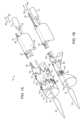
図1Aは、本発明のステントグラフト送達システムおよび本発明のステントグラフト送達システムにより送達されるステントグラフトの一態様の斜視図である。ここで示されるように、ステントグラフト送達システム10は、ハンドル12、およびハンドル12から遠位に伸長するガイドワイヤカテーテル14を含む。ガイドワイヤカテーテル14は、ハンドル12での近位端16および遠位端18を有する。ノーズコーン20は、ガイドワイヤカテーテル14の遠位端18に固定される。管22は、ハンドル12から遠位に伸長し、ガイドワイヤカテーテル14に実質的に並行である。管22は、ハンドル12での近位端24および遠位端26を含む。ワイヤ28は、管22を通って伸長し、管22の遠位端26でループ30として形成される。 FIG. 1A is a perspective view of one embodiment of a stent graft delivery system of the present invention and a stent graft delivered by the stent graft delivery system of the present invention. As shown here, stent
ステントグラフト32はガイドワイヤカテーテル14の周囲に伸長する。ステントグラフト32は、近位開口端34および遠位開口端36を含む。ステントグラフト32の管腔グラフト構成要素38は、外部表面40および内部表面42を有する。内部表面42は、グラフト管腔44を画定する。一態様において、適切な場合、管腔グラフト構成要素38は、輪郭で示されるような開窓46を画定する。管腔グラフト構成要素38は、当業者に公知のような適切な材料、例えば発泡(expanded)ポリテトラフルオロエチレン(ePTFE)およびポリエチレンテレフタレート(PET)、例えば織られたポリエステル(woven polyester)等で作製される。
ステント31、48は、管腔グラフト構成要素38の外部表面40に沿って分布される。示されるように、ステント31、48は、近位頂部52および遠位頂部54を画定するようにそれぞれの末端で連結される支柱50を含む。縫合糸56は、管22の遠位端26でステント48の支柱50の間に分布され、本明細書において「入れ子状(nested)」とも称される。ワイヤ28のループ30は、縫合糸56を通って伸長し、それによりステント48の支柱50を結ぶ。図1Aに示されるように、ワイヤ28は、弛緩された位置にあり、それによりループ30は、ステントグラフト32のステント48を半径方向に収縮しない。
図1Bに示されるように、矢印58により示される方向の管22を通るワイヤ28の近位の引き込みは、ループ30の半径方向の収縮を引き起こし、結果的に縫合糸56を通って伸長するループ30により結ばれるステント48の半径方向の収縮が起こる。一態様において、ステント48は、半径方向に自己拡張して、ワイヤ28の解放および近位の引き込みは、ステント48の選択的な収縮および半径方向の拡張を可能にし、それにより図1Aおよび図1Bに示される配置の間で、近位方向58または遠位方向60のいずれかにおける交替が可能になる。一態様において、ステント31、48は、半径方向の拘束からの解放の際にステントを半径方向に自己拡張させる材料で作製される。半径方向自己拡張ステントの適切な材料の例としては、形状記憶合金、例えばニチノールが挙げられる。形状記憶合金で形成されないステント31、48の例としては、ステンレス鋼で作製されるものが挙げられる。形状記憶合金を使用しないかまたはそうでなければ自己拡張しない本発明の態様において、当該技術分野で公知なように、半径方向の収縮から解放されたステントを半径方向に拡張させるために、例えばバルーンカテーテルが使用され得る。代替的に、ワイヤ28は、管22を通って伸長するワイヤ28の一部を矢印60で示される遠位方向に方向づけることによりステント48を半径方向に拡張させるのに十分な剛性を有し得る。 As shown in FIG. 1B, proximal retraction of
別の態様において、図2Aに示されるステントグラフト送達システム70は、図1Aに示されるものと類似するが、ガイドワイヤカテーテル14および管22と並行に整列されるさらなる管72およびワイヤ74をさらに含む。管72は、管72の遠位端78でループ76として形成されるワイヤ74を含む。ループ76は、縫合糸80に通され、それにより構成要素支柱84でステント82を結ぶ。図2Aに示されるように、両方のワイヤ28、74および関連のあるステント48、82は弛緩される(半径方向に自己拡張する場合)かまたはそうでなければ拡張される位置で示される。 In another embodiment, the stent
ステント、ワイヤ、ループ、管および縫合糸などのステントグラフト送達システムの構成要素はまた、当該技術分野で公知なように、硫酸バリウム、ビスマス、タングステン、白金-イリジウムおよびタンタル-タングステンからなる群より選択される少なくとも1つの放射線造影剤(radiopacifier)などの放射線不透過性構成要素を含み得る。 Components of the stent-graft delivery system, such as stents, wires, loops, tubes and sutures, may also be selected from the group consisting of barium sulfate, bismuth, tungsten, platinum-iridium and tantalum-tungsten, as known in the art. may include a radiopaque component, such as at least one radiopacifier.
図2Bは、図1Aのステントグラフト送達システムの表示であり、ここでワイヤ28、74は、矢印86に示される近位方向に引き込まれ、それによりステント48、82の両方が半径方向に収縮される。ステント48、82が半径方向に自己拡張する事象において、ワイヤ28、74のいずれかまたは両方の解放は、ワイヤを、矢印88により示される遠位方向に移動させる。ワイヤ28、74は互いに独立して制御され得て、ステント48、82のいずれかは、関連のあるワイヤ28、74のそれぞれにより半径方向に収縮され得、一方で他方のステントは弛緩されるかまたは拡張される位置にあることが理解される。さらにワイヤ28、74のそれぞれは、独立して制御され得るので、ワイヤ28、74のいずれかは、それぞれ独立して、関連のあるステントを、十分に半径方向に拡張される位置にする、十分に半径方向の収縮される位置にする、または十分に半径方向に拡張される位置と十分に半径方向に収縮される位置の間の任意の位置にする位置に維持され得る。 FIG. 2B is a representation of the stent graft delivery system of FIG. 1A in which
図3Aは、本発明のステントグラフト送達システムの代替的な態様の斜視図である。該図に示されるように、ステントグラフト送達システム100は、並行に整列された2つの管102、104を含む。ワイヤ106は、管102、104を通って伸長する部分を有し、ハンドル112において末端108、110を含む。ワイヤ106は、各管102、104のそれぞれを通って伸長するワイヤ106の部分116、118を連結するループ114を含む。管102、104それぞれのいずれかまたは両方を通って伸長するワイヤ106の部分116、118のいずれかまたは両方の引き込、支柱122の間に配置される縫合糸124を通って伸長するワイヤ106により結ばれる支柱122の収縮により、ステント120の半径方向の収縮を引き起こす。 FIG. 3A is a perspective view of an alternative embodiment of the stent graft delivery system of the present invention. As shown in the figure, stent
図3Bは、管102、104を通って伸長するワイヤ106の一方もしくは他方または両方の部分の矢印126に示される方向の近位引き込み後の図3Aのステントグラフト送達システムの表示であり、該引き込みにより、ステント120の半径方向の収縮が生じる。先に示される態様と同様に、ステント120は、適切な材料で作製され得、ステントは半径方向の自己拡張を示し、それにより管102、104のいずれかまたは両方を通るワイヤの選択的な解放および引き込み、ならびに図3Aおよび3Bに示されるステント120の半径方向の拡張と半径方向の収縮の間またはそれらの間の位置での、近位方向126または遠位方向128のいずれかにおける結果的な交替が可能になる。 FIG. 3B is a representation of the stent-graft delivery system of FIG. 3A after proximal retraction in the direction indicated by
図4Aに示される本発明のステントグラフト送達システム130は図3Aのものに類似するが、さらなる管132、134を含む。さらなるワイヤ142は管132、134を通って伸長し、ハンドル140において末端136、138を含む。ワイヤ142は、ステント120に対して遠位にあるループ146でステント144を結ぶ。ステント144の半径方向収縮は、ワイヤ142の近位および遠位の移動により制御可能である。ループ146の連結は支柱150の間の縫合糸148を通り、それによりワイヤ142がステント144の支柱150を結ぶ。 The stent
図2Aおよび2Bに示される態様と同様に、ワイヤ106、142は、ステント120、144を半径方向に収縮または拡張するように独立して制御され得る。図4Bに示されるように、両方のステント120、144は、図4Aのものに対して半径方向に収縮された位置に示される。ステント120、144は、それぞれ独立して、半径方向に拡張されるかもしくは半径方向に収縮される配置、またはそれらの間の任意の部分的に半径方向に収縮される位置に保持または維持され得る。より具体的に、図4Aおよび4Bそれぞれにおけるステントの示される位置は、近位矢印126および遠位矢印152のそれぞれにより示される近位および遠位の方向のワイヤ106、142の選択的な制御により変更され得る。 Similar to the embodiment shown in FIGS. 2A and 2B,
本発明のさらなる態様において、さらなるワイヤおよび連結ループが含まれ得、それらの全ては、ステントグラフトの管腔グラフト構成要素に沿って伸長する対応するステントを可変的に半径方向に収縮または半径方向に拡張するように独立して調節され得ることが理解される。また、図5Aおよび5Bに見られ得るように、本発明の別の送達システム160において、ワイヤ164がそれを通って伸長する管162は、外部表面170に沿った管腔グラフト構成要素168においてステントグラフト166に沿って整列され得る。管腔グラフト構成要素の外部表面170に沿って整列される場合、連結ループ172は、管腔グラフト構成要素168の外部表面170、および支柱176におけるステント174の周囲に伸長する。縫合糸178は支柱176の間に配置され、ワイヤ164はループ172で縫合糸178を通る。ワイヤ164は、方向165で近位に引き込まれ得るか、または自己拡張ステント174の場合、遠位方向167に移動して、ステント174をそれぞれ半径方向に収縮または半径方向に拡張し得る。 In further aspects of the invention, additional wires and connecting loops may be included, all of which variably radially contract or radially expand a corresponding stent extending along the luminal graft component of the stent graft. It is understood that it can be independently adjusted to do so. Also, as can be seen in FIGS. 5A and 5B, in another
図6Aは、本発明のステントグラフト送達システムの別の態様の遠位部分の断面であり、ステントグラフト送達システムからの解放前にステントグラフトを半径方向に収縮し得る。図6Aに見られるように、ステントグラフト送達システム190は、遠位端194および遠位端194で固定されるノーズコーン196を含むガイドワイヤカテーテル192を有する。頂部捕捉アセンブリ198は、ガイドワイヤカテーテル192の遠位端194に固定される遠位頂部捕捉部分200を含む。近位頂部捕捉部分202は歯(tine)204を含み、頂部解放カテーテル206は、近位頂部捕捉部分202が固定される遠位端208を含む。管210、212は、頂部解放カテーテル206に沿って、頂部解放カテーテル206およびガイドワイヤカテーテル192の両方と並行して伸長する。ワイヤ214は、連結ループ216で、縫合222により管腔グラフト構成要素220においてステントグラフト218を固定する。縫合糸222は、支柱226の間のステント224において間隔を開けられ、それにより縫合糸222を通るループ216がステント224の支柱226を結ぶ。図6Aの詳細である図6Bにおいてより明確に見られ得るように、ワイヤ214は管210、212を通って伸長し、それぞれの管210、212を通って伸長するワイヤ214の部分は、管210、212の遠位端228、230のそれぞれで連結ループ216により繋がれる。外部管232は管210、212、頂部解放カテーテル206およびガイドワイヤカテーテル192の周囲に伸長し、それにより管210、212、頂部解放カテーテル206およびガイドワイヤカテーテル192の間で互いに対する空間的な関係を固定する。外部管232の遠位端234は、ガイドワイヤカテーテル192に沿った、管210、212の遠位端228、230のものと同じ点の周囲に配置される。 FIG. 6A is a cross-section of a distal portion of another embodiment of the stent-graft delivery system of the present invention, which allows the stent-graft to be radially deflated prior to release from the stent-graft delivery system. As seen in FIG. 6A, stent
図6Aに戻り、ステントグラフト218は、管210、212および頂部解放カテーテル206を含む外部管232の周囲に伸長する。ステントグラフト218は、管腔グラフト構成要素220、管腔グラフト構成要素220に沿って伸長するステント224、および管腔グラフト構成要素220の近位端238におけるベアステント236を含む。ベアステント236は、ベアステント236の近位頂部240を画定する支柱225の間で伸長する歯204により、頂部捕捉アセンブリ198の近位頂部捕捉部分202において固定される近位頂部240を含む。ベアステント236の遠位頂部240は、管腔グラフト構成要素220の近位端238に固定される。ベアステント236の近位頂部240は、頂部解放カテーテル206の引き込みにより解放され、結果的に近位頂部捕捉部分202は、遠位捕捉部分200から離れ、それによりベアステント236の支柱225の間から歯204が引き込まれ、ニチノールなどの形状記憶合金で形成されたベアステント236は、歯204による拘束からの近位頂部240の解放の際に拡張される。図6Cは、図6Aに示される態様の断面図である。頂部捕捉アセンブリ198の作動により、ベアステント236はステントグラフト送達システム190から解放される。 Returning to FIG. 6A,
導入シース242は、管腔グラフト構成要素220の遠位端244でステントグラフト218の遠位端244を半径方向に収縮させ、図7および8A~8Eを参照して下記されるように、ステントグラフト218からの矢印243で示される方向の導入シース242の部分的な遠位の引き込みの後にステントグラフト218を部分的に半径方向に収縮させる。 The
図7は、本発明のステントグラフト送達システムの別の態様の構成要素の分解組立図である。該図に示されるように、ステントグラフト送達システム250は、近位端254および遠位端256を含むガイドワイヤカテーテル252を有する。近位ハンドル258は、ガイドワイヤカテーテル252の近位端254に固定され、ノーズコーン260は、ガイドワイヤカテーテル252の遠位端256に固定される。導入シース262は近位端264および遠位端266を含む。遠位ハンドル268は、導入シース262の近位端264に固定される。ワイヤ274、275は、ステントグラフト218から近位ハンドル258に伸長するのに十分な長さを有し、各管284、286のそれぞれに収容される。ループ285、287は管284、286から遠位に伸長する。 FIG. 7 is an exploded view of the components of another embodiment of the stent-graft delivery system of the present invention. As shown in the figure, stent
図8Aは、組み立てられた形態の図7に示される構成要素部分の表示である。集合される場合、管284、286は、近位ハンドル258およびワイヤ274、275のそれぞれの一方の端のそれぞれに固定される。ワイヤ274、275のそれぞれの他方の端は、ハンドル258を通って伸長し、近位に引き込み可能であり、それによりワイヤループ285、287がその中を通るステント277を結ぶ縫合糸で、ステントグラフト272を半径方向に収縮する。導入シース262は、ガイドワイヤカテーテル252の遠位端256の周囲に伸長する。示されないが、ステントグラフト272は導入シース262に含まれる。本発明の方法の一態様において、ステントグラフト送達デバイス250は、導入シース262および導入シース262に含まれるステントグラフト272などの血管プロテーゼが患者の動脈瘤270に位置するまで、患者の動脈内を進む。遠位ハンドル268および結果的に導入シース262は、近位ハンドル258に向かって引き込まれ、それにより図8Aから図8Bへの移り変わりにおいて示されるように、ステントグラフト272が少なくとも部分的に暴露される。代替的な態様において、ステントグラフト送達システム250は、導入シース262およびそれに含まれるステントグラフト272が患者の動脈瘤270の遠位に配置されるまで、患者の動脈内を進み得ることが理解される。この態様において、近位ハンドル258、およびステントグラフト272が直接または間接的に固定されるガイドワイヤカテーテル252は、遠位ハンドル268に向かって遠位に進み、ステントグラフト272は少なくとも部分的に、導入シース262から動脈瘤270まで進み、図8Bに示される表示が生じる。 FIG. 8A is a representation of the component parts shown in FIG. 7 in assembled form. When assembled,
いずれかの態様において、本発明のステントグラフト送達システムのワイヤ274、275は、ステント276、277のそれぞれで、ステントグラフト272を収縮する。図8Bおよび8Cに示されるように、ワイヤ274、275はステントグラフト272の遠位端278でステント276、277を半径方向に収縮する。一態様において、ステントグラフト272は開窓273を含む。ステント276、277は、図8Bから図8Cへの移り変わりにおいて示されるようなワイヤ274、275の近位および遠位の移動により選択的に制御され得、該図の移り変わりはステント277の遠位にあるステント276が、ステント276の周囲に伸長するループを有するワイヤ274の張力の緩和によるなどの矢印289の方向のワイヤ274の遠位の移動の結果として半径方向の拡張を示し、ステント276の半径方向の拡張を引き起こすことを示す。図8Cに示されるように、ステント277のみが半径方向に収縮されたままでいる。ステント276、277のそれぞれが半径方向に自己拡張している、例えばステントがニチノールなどの適切な形状記憶合金で作製される例において、ワイヤ274、275の張力の緩和により、ステント276、277のそれぞれの半径方向の拡張が生じる。代替的に、ステント276、277が半径方向に自己拡張しない場合は、ステント276、277は、ステント276、277の半径方向の拡張を生じるのに十分に堅いワイヤ274、275を使用すること、または当該技術分野で公知のものなどのバルーンカテーテル(示さず)を使用することにより、半径方向に拡張され得る。 In either embodiment,
ステント276、277のそれぞれを半径方向に収縮させるワイヤ274、275を逆の順序で解放させて、それにより関連のあるワイヤ274によりステント276を収縮させたままにし、ステント277が半径方向の拡張を示し得ることも理解される。さらに、ステント276、277のいずれかまたは両方は、それぞれの各ワイヤを矢印291に示される近位の方向に移動させることにより半径方向に収縮され得る。また、ワイヤ274、275は互いに独立して制御され得、それぞれのワイヤの張力を独立してかつ可変的に制御して、動脈瘤部位におけるステントグラフトの適切な回転方向および長手方向の調節の際に、関連のあるステントの半径方向の拡張を調節する。さらに別の態様において、本発明のステントグラフト送達システムは、上述のように1つのみのワイヤを含み得、それにより1つのみのステントの収縮を生じ得る。 The
ステントグラフト272のそれぞれの各ステント276、277を半径方向に収縮する両方のワイヤ274、275の解放または遠位の移動の際に、ステント276、277の両方は、被験体の動脈瘤270を占めるような半径方向の拡張を示す。ステントグラフト272がステントグラフト272の近位端282でベアステント280を含む態様において、ベアステント280は、図8Dに示されるように、頂部捕捉アセンブリ293で固定されたままであり得る。この態様において、頂部捕捉アセンブリ293の作動によるベアステント280の近位頂部286の解放は、ベアステント280を、動脈瘤270のちょうど頭方にある動脈の一部に接地させる。図8Eに示されるように、ワイヤ274、275は、例えばそれぞれのワイヤ274、275の一方の末端を引いて、ステントグラフト送達システム250の残りからワイヤを引き込むことにより、またはワイヤ274、275の連結を近位ハンドル258から切断することにより、ステント276、277を半径方向に拡張させるようにワイヤ274、275の張力を解放させた後の任意の時点で取り除かれ得る。その後、ステントグラフト送達システム250の残りは、ステントグラフト272内および患者から引き込まれ、それにより図8Eにも示されるように、ステントグラフト272の埋め込みおよび動脈瘤270の治療が完了し得る。一態様において、ステントグラフト272は、開窓273を通る動脈分枝281への分枝プロテーゼ287のその後の設置のために、開窓273が、動脈分枝281と適切に整列されるように配置される。その後、ステントグラフト272は動脈瘤270内に完全に埋めこまれ、ステントグラフト送達システム250の残りは、図8Eに示されるように、ステントグラフト272および患者から引き込まれ、それにより本発明の方法による患者の動脈瘤270の治療が完了する。 Upon release or distal movement of both
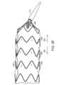
図9Aは、ステントグラフトプロテーゼ290内のそれぞれのワイヤ(示さず)による、3つのステント294、296、298の半径方向の収縮を示す本発明のステントグラフト送達システム292のステントグラフトプロテーゼ290の一部の部分的な側面図である。プロテーゼ290の近位端302においてベアステント300は、頂部捕捉アセンブリ306によりベアステント300の近位頂部204で固定される。図9Aにも見られ得るように、ガイドワイヤカテーテル(示さず)はアーチ状であり、それによりステントグラフトプロテーゼ290は遠位端310でアーチ状になる。ノーズコーン311はガイドワイヤカテーテルの遠位端310にある。また、ステントグラフトプロテーゼ290は、収縮されたステント294、296、298の間で少なくとも1つの開窓またはスカラップ(scallop)(示さず)を画定し得、この場合において該ステントは半径方向に自己拡張し、ステントの半径方向の収縮は、上述のように、ステント294、296、298の支柱の間の縫合糸を通るループの張力により決定されることが理解される。ガイドワイヤカテーテル308をその遠位端310でアーチとして形成することは、大動脈弓などのアーチ状の動脈血管に開窓(示さず)が配置される態様において有益である。それぞれのステント294、296、298のそれぞれにおいてループ(示さず)を制御するワイヤ上の張力の独立した変化または該ワイヤの遠位の移動により、ステントグラフトプロテーゼ290の整列および埋め込みの際の外科医による制御が向上される。ワイヤの遠位の移動は矢印303で示される。ワイヤの近位の移動は矢印305で示される。ステントグラフトプロテーゼ290の整列はまた、ステントグラフトプロテーゼ290の動脈瘤部位への進行の際に、ステントグラフトプロテーゼ290の回転方向の配向を容易にして、それにより大動脈弓における動脈分枝などの、開窓における動脈分枝と任意の開窓との整列を向上する、ガイドワイヤカテーテル308のアーチにより向上される。 FIG. 9A shows a partial portion of a stent-
図9Bは、図9Aに示されるステントグラフトプロテーゼ290およびステントグラフト送達システム292の部分的な側面図であり、ここでそれぞれのステント294、296、298を収縮する3つのワイヤの2つは、解放されているかまたは遠位に移動されて、それによりステントグラフト送達システムのそれぞれの束縛ワイヤにより収縮された形状のままである第3のステント294に対して近位にある2つのステント294、296の半径方向の拡張が可能になる。図9Cは、図9Bに示される態様の末端図であり、ここでステント298を以前に収縮した最遠位のワイヤ318は緩和されるかまたは遠位に移動されるが、ステントグラフト290において縫合糸320を通ったままである。図9Dは、図9Aに示されるステントグラフト送達システム292のステントグラフトプロテーゼ290の部分的な側面図であり、ここでステント294、296を以前に収縮したワイヤ314、316上のステント298に対する張力は、緩和されるかまたは遠位に移動され、それによりステント298が半径方向に収縮された位置にあるままで、ステント294、296の半径方向の拡張が可能になる。 FIG. 9B is a partial side view of the stent-
図9Eは、図9Dに示される配置におけるステントグラフト290および送達システム292の末端図であり、ここで最近位のステント298を収縮するワイヤ318は、依然として収縮された位置にある。図9Fは、図9A~9Eに示されるステントグラフトプロテーゼ292の側面図であり、ここでステント294、296、298を以前に収縮した全てのワイヤ314、316、318上の張力は緩和されている。図9Gは、図9Fに示されるステントグラフトプロテーゼの配置の末端図であり、ここでステント294、296で縫合糸320を通って伸長する2つの最遠位のワイヤ316、318は、緩和されるかまたは遠位に移動されるが、ステント294、296、298の支柱の間でステントグラフト290において縫合糸320を通ったままである。内部管330は、管322、324および頂部解放カテーテル334の周囲に伸長する。外部管332は、内部管330および管326、328の周囲に伸長する。図9Hは、管322、324から伸長するワイヤ316、318および内部管330から伸長する管326、328の詳細である。 FIG. 9E is an end view of the
本発明のステントグラフトシステムおよび方法により埋めこまれる血管プロテーゼは、例えば経大腿(transfemoral)アクセスにより埋めこまれ得る。本発明の血管プロテーゼに方向づけられるさらなる分枝プロテーゼは、例えば大動脈上(supraaortic)血管アクセス(例えば上腕動脈を通る)、または経大腿アクセスもしくは末梢血管を含む主要血管のいくつかの他の分枝からのアクセスにより埋めこまれ得る。 Vascular prostheses implanted by the stent-graft systems and methods of the present invention may be implanted, for example, via transfemoral access. Further branch prostheses directed to the vascular prosthesis of the invention may be obtained, for example, from supraaortic vascular access (e.g. through the brachial artery), or from some other branch of the main vessel, including transfemoral access or peripheral vessels. can be embedded by access.
本明細書に引用される全ての特許、公開出願および参照文献の教示は、それらの全体において、参照により援用される。本明細書に引用される全ての特許、公開出願および参照文献の関連のある教示は、それらの全体において、参照により援用される。米国特許第8,292,943号、第7,763,063号、第8,308,790号、第8,070,790号、第8,740,963号、第8,007,605号、第9,320,631号、第8,062,349号、第9,198,786号、第8,062,345号、第9,561,124号、第9,173,755号、第8,449,595号、第8,636,788号、第9,333,104号、第9,408,734号、第9,408,735号、第8,500,792号、第9,220,617号、第9,364,314号、第9,101,506号、第8,998,970号、第9,554,929号、第9,439,751号、第9,592,112号、第9,655,712号、第9,827,123号、第9,877,857号、第9,907,686号、米国特許出願第14/575,673号、第15/166,818号、第15/167,055号、第14/272,818号、第14/861,479号、第15/478,424号、第15/478,737号、第15/587,664号、第15/604,032号、第15/672,404号、第15/816,772号、第15/839,272号、第15/417,467号、PCT/US2017/025844、PCT/US2017/025849、PCT/US2017/025912、PCT/US2017/034223およびPCT/US2017/046062の関連のある教示も、それらの全体において参照により援用される。 The teachings of all patents, published applications, and references cited herein are incorporated by reference in their entirety. The relevant teachings of all patents, published applications, and references cited herein are incorporated by reference in their entirety. U.S. Pat. , No. 561,124, No. 9,173,755, No. 8,449,595, No. 8,636,788, No. 9,333,104, No. 9,408,734, No. 9,408,735, No. 8,500,792, No. 9,220,617, No. 9,364,314, No. 9,101,506, No. 8,998,970, No. 9,5 No. 54,929, No. 9,439,751, No. 9,592,112 No. 9,655,712, No. 9,827,123, No. 9,877,857, No. 9,907,686; , No. 15/478,424, No. 15/478,737, No. 15/587,664, No. 15/604,032, No. 15/672,404, No. 15/816,772, No. 15/839,272, No. 15/417,467, PCT The relevant teachings of /US2017/025844, PCT/US2017/025849, PCT/US2017/025912, PCT/US2017/034223 and PCT/US2017/046062 are also incorporated by reference in their entirety.
2018年2月23日に出願されたSamuel Arbefeuilleによる「System and Method to Radially Constrict Stent Graft」、Attorney Docket No.: 4221.1044-001;2018年2月23日に出願されたTimothy Lostetterによる「Delivery System and Method to Radially Constrict a Stent Graft」、Attorney Docket No.: 4221.1046-001;2018年2月23日に出願されたSamuel Arbefeuilleによる「Vascular Prosthesis with Moveable Fenestration and Method of Use」、Attorney Docket No.: 4221.1047-001;2018年2月23日に出願されたTimothy Lostetterによる「Stent Graft Delivery System with Constricted Sheath and Method of Use」、Attorney Docket No.: 4221.1048-001;2018年2月23日に出願されたTimothy Lostetterによる「Stent Graft with Fenestration Lock and Methods of Use」、Attorney Docket No.: 4221.1049-001;2018年2月23日に出願されたSamuel Arbefeuille and Nico Baharによる「Stent Graft, Delivery System and Methods of Use」、Attorney Docket No.: 4221.1050-001;2018年2月23日に出願されたSamuel Arbefeuilleによる「Vascular Prosthesis with Crimped Adapter and Methods of Use」、Attorney Docket No.: 4221.1052-001;2018年2月23日に出願されたSamuel Arbefeuille, Eduardo Alejandro Garcia and Scott L. Rushによる「Radially Adjustable Stent Graft Delivery System and Method of Use」、Attorney Docket No.: 4221.1053-001;2018年2月23日に出願されたTimothy Lostetterによる「Vascular Prosthesis with Fenestration Ring and Methods of Use」、Attorney Docket No.: 4221.1054-001;2018年2月23日に出願されたSamuel Arbefeuilleによる「Distal Torque Component, Delivery System and Method of Using Same」、Attorney Docket No.: 4221.1055-001の関連のある教示も、それらの全体において参照により援用される。 "System and Method to Radically Constrict Stent Graft" by Samuel Arbefeuille, filed on February 23, 2018, Attorney Docket No.: 4221.1044-001; "Delivery System and Method to Radically Constrict Stent Graft" by Timothy Lostetter, filed on February 23, 2018; "Vascular Prosthesis with Moveable Fenestration and Method of Use" by Samuel Arbefeuille, filed on February 23, 2018, Attorney Docket No.: 4221.1046-001; Attorney Docket No.: 4221.1047- 001; “Stent Graft Delivery System with Constricted Sheath and Method of Use” by Timothy Lostetter, filed on February 23, 2018, Attorney Docket No.: 4221.1048-001; Timothy Lostetter, filed on February 23, 2018 "Stent Graft with Fenestration Lock and Methods of Use" by Samuel Arbefeuille and Nico Bahar, Attorney Docket No.: 4221.1049-001; "Stent Graft, Delivery System and Methods of Use" by Samuel Arbefeuille and Nico Bahar, filed on February 23, 2018; Attorney Docket No.: 4221.1050-001; “Vascular Prosthesis with Crimped Adapter and Methods of Use” by Samuel Arbefeuille, filed on February 23, 2018; Attorney Docket No.: 4221.1052-001; filed on February 23, 2018; "Radially Adjustable Stent Graft Delivery System and Method of Use" filed by Samuel Arbefeuille, Eduardo Alejandro Garcia and Scott L. Rush, Attorney Docket No.: 4221.1053-001; filed February 23, 2018 by Timothy Lostetter “Vascular Prosthesis with Fenestration Ring and Methods of Use”, Attorney Docket No.: 4221.1054-001; “Distal Torque Component, Delivery System and Method of Using Same” by Samuel Arbefeuille, filed February 23, 2018, Attorney Docket The relevant teachings of No.: 4221.1055-001 are also incorporated by reference in their entirety.
例示態様が具体的に示され、記載されているが、形態および詳細における種々の変更が、添付の特許請求の範囲に包含される態様の範囲から逸脱することなく、本発明においてなされ得ることが、当業者には理解されよう。 While illustrative embodiments have been particularly shown and described, it is understood that various changes in form and detail may be made in the invention without departing from the scope of the embodiments within the scope of the appended claims. , as will be understood by those skilled in the art.
本発明の態様として以下のものが挙げられる。
[1]a) ハンドル;
b) 該ハンドルから遠位に伸長し、かつ遠位端を有するガイドワイヤカテーテル;
c) 近位端および遠位端を有する少なくとも1つの管、ここで該管は、ハンドルから遠位に伸長し、かつガイドワイヤカテーテルと並行して整列される;および
d) 少なくとも1つの管を通って伸長する少なくとも1つのワイヤ、ここでそれぞれのワイヤは、管の遠位端でループとして形成され、かつハンドルで少なくとも1つの近位端を有する、
を含む、ステントグラフト送達システム。
[2]少なくとも1つの管が、並行して整列される管の第1の組であり、該ワイヤが、2つの管を通って伸長し、ループが、それぞれの各管内に伸長するワイヤの一部を連結する、[1]記載のステントグラフト送達システム。
[3]近位端および遠位端を有しかつ管腔を画定するステントグラフトをさらに含むステントグラフト送達システムであって、該ステントグラフトがガイドワイヤカテーテルおよび少なくとも2つの管の周囲に伸長し、該管の遠位端が管腔内にあり、該ワイヤのループがステントグラフトを少なくとも部分的に固定し、送達デバイスの近位端でワイヤを引くことにより、ループの長さの減少および結果的にループでのステントグラフトの半径方向の収縮が生じる、[2]記載のステントグラフト送達システム。
[4]該ステントグラフトが、複数のステントおよび管腔グラフト構成要素を含み、該ステントがそれぞれ、管腔グラフト構成要素の周囲に伸長し、かつ管腔グラフト構成要素の長手軸に沿って分布され、該ステントの少なくとも一部が、近位頂部および遠位頂部を画定するように連結される支柱を含む、[3]記載のステントグラフト送達システム。
[5]該ステントグラフトがさらに、複数の縫合糸ループを含み、該ワイヤが縫合糸ループを通って伸長し、それによりステントグラフトが固定される、[3]記載のステントグラフト送達システム。
[6]該ステントグラフトが、近位端にベアステントを含み、該ベアステントが、ガイドワイヤ管腔の遠位端で固定される、[5]記載のステントグラフト送達システム。
[7]2つのワイヤをさらに含むステントグラフト送達システムであって、それぞれのワイヤのループが、互いに対してガイドワイヤ管腔の長手軸に沿って長手方向に整列される、[6]記載のステントグラフト送達システム。
[8]該縫合糸が、ステントの支柱の間で入れ子状になり、該縫合糸を通って伸長するワイヤの引き込みが、それぞれのループの半径方向の収縮、および結果的にステントの半径方向の収縮を引き起こす、[5]記載のステントグラフト送達システム。
[9]該ワイヤの少なくとも一部のそれぞれが、ステントグラフトにおいて、複数の縫合糸を通って伸長する、[8]記載のステントグラフト送達システム。
[10]複数の縫合糸が、それぞれのステントのそれぞれの近位頂部に対して遠位に入れ子状になる、[9]記載のステントグラフト送達システム。
[11]少なくとも2つのワイヤが、ステントグラフトにおいて、縫合糸を通って伸長する、[8]記載のステントグラフト送達システム。
[12]ワイヤのそれぞれが、ステントグラフトのそれぞれのステントを半径方向に収縮する、[11]記載のステントグラフト送達システム。
[13]ワイヤのそれぞれが、少なくとも2つの縫合糸を通って伸長し、該縫合糸のそれぞれが、それぞれのステントの近位頂部に対して遠位に入れ子状になる、[12]記載のステントグラフト送達システム。
[14]該ワイヤが独立して操作可能である、[12]記載のステントグラフト送達システム。
[15]少なくとも1つのワイヤのそれぞれの近位端の1つでワイヤハンドルをさらに含むステントグラフト送達システムであって、それぞれのワイヤが、それぞれのハンドルの近位の引き込みまたは前進により操作可能である、[12]記載のステントグラフト送達システム。
[16]複数のワイヤが、近位端でワイヤハンドルに集合的に固定され、ステントグラフトに沿って長手方向にワイヤハンドルを遠位または近位に移動させることで、ワイヤが、ステントグラフトの半径方向の収縮を集合的に増加または減少させる、[15]記載のステントグラフト送達システム。
[17]該ワイヤの少なくとも一部がそれぞれ独立して、それらの近位端のそれぞれで別個のワイヤハンドルに固定され、ステントグラフトに沿って長手方向にそれぞれのワイヤハンドルを遠位および近位に移動させることで、ワイヤが、少なくとも1つの他のワイヤおよびそれぞれのワイヤハンドルと独立して作動して、それぞれの縫合糸ループでステントグラフトの対応する部分の半径方向の収縮を独立して増加または減少させ、それぞれの各ワイヤループが該縫合糸ループを通り抜ける、[15]記載のステントグラフト送達システム。
[18]少なくとも1つのワイヤが形状記憶材料で形成される、[1]記載のステントグラフト送達システム。
[19]該形状記憶材料がニチノールを含む、[18]記載のステントグラフト送達システム。
[20]該ワイヤが独立して、ステントグラフト送達システムの残りから解放可能であり、該ワイヤが、ステントグラフトにおいて縫合糸から取り除かれ得、それによりステントグラフトがワイヤから解放される、[1]記載のステントグラフト送達システム。
[21]a) ステントグラフトを、被験体の動脈瘤部位に方向づける工程、ここで該ステントグラフトの近位端は、少なくとも1つの管を通って伸長し、かつ送達システムにおいてステントグラフトに少なくとも部分的に固定されるループとして形成される少なくとも1つのワイヤにより半径方向に収縮された位置に保持されている;ならびに
b) 遠位または近位の方向にハンドルにおいてワイヤの少なくとも1つの近位端を可変的に移動させ、動脈瘤でのステントグラフトの軸方向および長手方向の整列を補助するようにステントグラフトの半径方向の収縮を可変的に増加および減少させ、それにより被験体の動脈瘤にステントグラフトを埋め込む工程
を含む、被験体の動脈瘤部位にステントグラフトを埋め込む方法。
[22]該少なくとも1つの管が、並行して整列される管の第1の組であり、該ワイヤが、2つの管を通って伸長し、該ループが、それぞれの各管内を伸長するワイヤの一部を連結する、[21]記載の方法。
[23]近位端および遠位端を有するステントグラフト、ガイドワイヤカテーテルの周囲に伸長するステントグラフトおよび少なくとも2つの管をさらに含む、方法であって、該ステントグラフトの近位端がガイドワイヤカテーテルの遠位端にあり、該ワイヤのループがステントグラフトを少なくとも部分的に固定し、送達デバイスの近位端でワイヤを近位方向に引くことで、ループの長さの低減および結果的にループでのステントグラフトの半径方向の収縮が生じる、[22]記載の方法。
[24]該ステントグラフトが、複数のステントおよび管腔グラフト構成要素を含み、該ステントが、それぞれ管腔グラフト構成要素の周囲に伸長し、かつ管腔グラフト構成要素の長手軸に沿って分布され、該ステントの少なくとも一部が、近位頂部および遠位頂部を画定するように連結される支柱を含む、[23]記載の方法。
[25]該ステントグラフトが複数の縫合糸ループをさらに含み、該ワイヤが縫合糸ループを通って伸長し、それによりステントグラフトを固定する、[23]記載の方法。
[26]該ステントグラフトが近位端でベアステントを含み、該ベアステントがガイドワイヤ管腔の遠位端で固定される、[25]記載の方法。
[27]2つのワイヤをさらに含む方法であって、それぞれのワイヤのループが、互いに対して、ガイドワイヤ管腔の長手軸に沿って長手方向に整列される、[26]記載の方法。
[28]該縫合糸がステントの支柱の間で入れ子状になり、縫合糸を通って伸長するワイヤの引き込みにより、それぞれのループの半径方向の収縮および結果的にステントの半径方向の収縮が生じる、[25]記載の方法。
[29]該ワイヤの少なくとも一部のそれぞれが、ステントグラフトにおいて、複数の縫合糸を通って伸長する、[28]記載の方法。
[30]複数の縫合糸が、それぞれのステントのそれぞれの近位頂部に対して遠位に入れ子状になる、[29]記載の方法。
[31]少なくとも2つのワイヤが、ステントグラフトにおいて、縫合糸を通って伸長する、[28]記載の方法。
[32]該ワイヤのそれぞれが、ステントグラフトのそれぞれのステントを半径方向に収縮させる、[21]記載の方法。
[33]ワイヤのそれぞれが少なくとも2つの縫合糸を通って伸長し、該縫合糸のそれぞれが、それぞれのステントの近位頂部に対して遠位に入れ子状になる、[32]記載の方法。
[34]少なくとも1つのワイヤのそれぞれの近位端の1つでワイヤハンドルをさらに含む方法であって、それぞれのワイヤが、それぞれのハンドルの近位の収縮または遠位の前進により操作可能である、[32]記載の方法。
[35]複数のワイヤが近位端でワイヤハンドルに集合的に固定され、ステントグラフトに沿って長手方向にワイヤハンドルを遠位または近位に移動させることで、ワイヤが、ステントグラフトの半径方向の収縮を集合的に増加または減少する、[34]記載の方法。
[36]該ワイヤが独立して操作可能である、[32]記載の方法。
[37]該ワイヤの少なくとも一部がそれぞれ独立して、それらのそれぞれの近位端で別個のワイヤハンドルに固定され、ステントグラフトに沿って長手方向にそれぞれのワイヤハンドルを遠位および近位に移動させることで、ワイヤが、少なくとも1つの他のワイヤおよびそれぞれのワイヤハンドルとは独立して作動して、それぞれの縫合糸ループでステントグラフトの対応する部分の半径方向の収縮を独立して増加または減少させ、それぞれの各ワイヤが該縫合糸ループを通り抜ける、[36]記載の方法。
[38]少なくとも1つのワイヤが形状記憶材料で形成される、[21]記載の方法。
[39]該形状記憶材料がニチノールを含む、[38]記載の方法。
[40]該ワイヤが、ステントグラフト送達システムの残りから独立して解放可能であり、該ワイヤがステントグラフトにおいて縫合糸から取り除かれ得、それによりステントグラフトが該ワイヤから解放される、[21]記載の方法。 Aspects of the present invention include the following.
[1] a) Handle;
b) a guidewire catheter extending distally from the handle and having a distal end;
c) at least one tube having a proximal end and a distal end, where the tube extends distally from the handle and is aligned parallel to the guidewire catheter; and
d) at least one wire extending through the at least one tube, where each wire is formed as a loop at the distal end of the tube and has at least one proximal end at the handle;
A stent-graft delivery system, including:
[2] The at least one tube is a first set of tubes arranged in parallel, the wire extending through the two tubes, and the loop being a set of wires extending into each respective tube. The stent graft delivery system according to [1], wherein the stent graft delivery system connects the parts.
[3] A stent-graft delivery system further comprising a stent-graft having a proximal end and a distal end and defining a lumen, the stent-graft extending around a guidewire catheter and at least two tubes, the stent-graft extending around a guidewire catheter and at least two tubes; With the distal end within the lumen and the loop of wire at least partially securing the stent graft, pulling the wire at the proximal end of the delivery device reduces the length of the loop and results in The stent graft delivery system according to [2], wherein radial contraction of the stent graft occurs.
[4] the stent graft includes a plurality of stents and lumen graft components, each of the stents extending about and distributed along a longitudinal axis of the lumen graft component; The stent-graft delivery system of [3], wherein at least a portion of the stent includes struts connected to define a proximal apex and a distal apex.
[5] The stent graft delivery system of [3], wherein the stent graft further includes a plurality of suture loops, and the wire extends through the suture loops, thereby securing the stent graft.
[6] The stent graft delivery system of [5], wherein the stent graft includes a bare stent at the proximal end, and the bare stent is secured at the distal end of the guidewire lumen.
[7] The stent graft delivery system of [6], further comprising two wires, the loops of each wire being longitudinally aligned along the longitudinal axis of the guidewire lumen with respect to each other. system.
[8] The suture is nested between the struts of the stent, and retraction of the wire extending through the suture causes radial contraction of each loop and consequent radial contraction of the stent. The stent graft delivery system according to [5], which causes contraction.
[9] The stent graft delivery system of [8], wherein each of the at least a portion of the wires extends through a plurality of sutures in the stent graft.
[10] The stent-graft delivery system of [9], wherein the plurality of sutures are nested distally to a respective proximal apex of a respective stent.
[11] The stent graft delivery system of [8], wherein at least two wires extend through the suture in the stent graft.
[12] The stent graft delivery system of [11], wherein each of the wires radially constricts a respective stent of the stent graft.
[13] The stent graft of [12], wherein each of the wires extends through at least two sutures, each of the sutures being nested distally to the proximal apex of the respective stent. delivery system.
[14] The stent graft delivery system according to [12], wherein the wires are independently manipulable.
[15] A stent graft delivery system further comprising a wire handle at one of the proximal ends of each of the at least one wire, each wire being operable by proximal retraction or advancement of the respective handle; [12] The stent graft delivery system described in [12].
[16] A plurality of wires are collectively secured to a wire handle at the proximal end, and moving the wire handle distally or proximally along the stent graft causes the wires to move in the radial direction of the stent graft. The stent-graft delivery system of [15], which collectively increases or decreases contraction.
[17] at least a portion of the wires are each independently secured to a separate wire handle at each of their proximal ends and moving each wire handle distally and proximally longitudinally along the stent graft; causing the wires to operate independently of the at least one other wire and each wire handle to independently increase or decrease radial contraction of a corresponding portion of the stent graft at each suture loop; , each wire loop passing through the suture loop.
[18] The stent graft delivery system according to [1], wherein at least one wire is formed of a shape memory material.
[19] The stent graft delivery system according to [18], wherein the shape memory material comprises nitinol.
[20] The stent graft of [1], wherein the wire is independently releasable from the rest of the stent graft delivery system, and the wire can be removed from the suture at the stent graft, thereby releasing the stent graft from the wire. delivery system.
[21] a) directing a stent graft to an aneurysm site in a subject, wherein the proximal end of the stent graft extends through at least one vessel and is at least partially secured to the stent graft in a delivery system; held in a radially contracted position by at least one wire formed as a loop; and
b) variably moving at least one proximal end of the wire in the handle in a distal or proximal direction, radially aligning the stent graft to aid in axial and longitudinal alignment of the stent graft at the aneurysm; A method of implanting a stent graft at an aneurysm site in a subject, the method comprising variably increasing and decreasing constriction thereby implanting the stent graft into the aneurysm of the subject.
[22] the at least one tube is a first set of tubes aligned in parallel, the wire extending through the two tubes, and the loop extending within each respective tube; [21] The method according to [21], wherein a part of the .
[23] A method further comprising a stent graft having a proximal end and a distal end, the stent graft extending about a guidewire catheter, and at least two tubes, the proximal end of the stent graft extending about a guidewire catheter, the proximal end of the stent graft extending about a guidewire catheter. at the end, the loop of the wire at least partially secures the stent-graft, and pulling the wire proximally at the proximal end of the delivery device reduces the length of the loop and results in the stent-graft at the loop. The method according to [22], wherein radial contraction occurs.
[24] The stent graft includes a plurality of stents and lumen graft components, each of the stents extending around the lumen graft component and distributed along the longitudinal axis of the lumen graft component; The method of [23], wherein at least a portion of the stent includes struts connected to define a proximal apex and a distal apex.
[25] The method of [23], wherein the stent graft further includes a plurality of suture loops, and the wire extends through the suture loops, thereby securing the stent graft.
[26] The method of [25], wherein the stent graft includes a bare stent at a proximal end, and the bare stent is secured at a distal end of the guidewire lumen.
[27] The method of [26], further comprising two wires, the loops of each wire being longitudinally aligned with respect to each other along the longitudinal axis of the guidewire lumen.
[28] The suture is nested between the struts of the stent, and retraction of the wire extending through the suture causes radial contraction of each loop and resultant radial contraction of the stent. , [25].
[29] The method of [28], wherein each of the at least a portion of the wire extends through a plurality of sutures in the stent graft.
[30] The method of [29], wherein the plurality of sutures are nested distally to a respective proximal apex of a respective stent.
[31] The method of [28], wherein at least two wires extend through the suture in the stent graft.
[32] The method of [21], wherein each of the wires radially constricts a respective stent of the stent graft.
[33] The method of [32], wherein each of the wires extends through at least two sutures, each of the sutures being nested distally to the proximal apex of the respective stent.
[34] The method further comprising a wire handle at one of the proximal ends of each of the at least one wire, wherein each wire is operable by proximal retraction or distal advancement of the respective handle. , [32].
[35] A plurality of wires are collectively secured to a wire handle at the proximal end, and moving the wire handle distally or proximally along the stent graft causes the wires to cause radial contraction of the stent graft. The method according to [34], wherein the method collectively increases or decreases.
[36] The method according to [32], wherein the wire is independently operable.
[37] at least a portion of the wires are each independently secured to separate wire handles at their respective proximal ends, and moving the respective wire handles distally and proximally longitudinally along the stent graft; causing the wire to operate independently of at least one other wire and the respective wire handle to independently increase or decrease radial contraction of a corresponding portion of the stent graft at each suture loop. The method of [36], wherein each wire is passed through the suture loop.
[38] The method according to [21], wherein at least one wire is formed of a shape memory material.
[39] The method according to [38], wherein the shape memory material contains nitinol.
[40] The method of [21], wherein the wire is releasable independently from the rest of the stent graft delivery system, and the wire can be removed from the suture at the stent graft, thereby releasing the stent graft from the wire. .
Claims (20)
Translated fromJapaneseb) 該ハンドルから遠位に伸長し、かつ遠位端(18)および長手軸を有するガイドワイヤカテーテル(14)、ここで該ガイドワイヤカテーテルは、その遠位端でアーチ状である;
c) 近位端(24)および遠位端(26)を有する少なくとも1つの管(22)、ここで該管は、ハンドルから遠位に伸長し、かつガイドワイヤカテーテルと平行に整列される;
d) 少なくとも1つの管を通って伸長する少なくとも1つのワイヤ(28)、ここでそれぞれのワイヤは、管の遠位端でループ(30)として形成され、かつハンドルで少なくとも1つの近位端(24)を有し、該少なくとも1つのワイヤが形状記憶材料で形成される;ならびに
e) ステントグラフト(32)、ここで該ステントグラフト(32)は、
i) 近位開口端(34)および遠位開口端(36)、
ii) 長手軸、
iii) グラフト管腔(44)を画定する内部表面(42)を有する管腔グラフト構
成要素(38)、
iv) 複数のステント(31、48)、ここで該複数のステント(31、48)は、そ
れぞれ、管腔グラフト構成要素の周囲に伸長し、かつ管腔グラフト
構成要素の長手軸の周囲に分布され、該ステントの少なくとも一部
が、近位頂部(52)および遠位頂部(54)を画定するように連結される
支柱(50)を含む、および
v) ステントの支柱(50)の間で入れ子状になっている複数の縫合糸(56)、
ここで該少なくとも1つのワイヤ(28)は、縫合糸(56)を通って伸長し、
それによりステントグラフト(32)が固定される、
を有する、
を含む、ステントグラフト送達システム(10)であって、該ステントグラフト(32)が、ガイドワイヤカテーテル(14)の周囲に伸長し、該ワイヤ(28)のループ(30)が、ステントグラフトを少なくとも部分的に固定し、該少なくとも1つのワイヤ(28)のループ(30)の長さが減少するように該送達デバイスの近位端で該ワイヤ(28)を引くことにより縫合糸(56)を通って伸長するワイヤ(28)を引き込むことが、ループ(30)の半径方向の収縮、ならびに結果的にループ(30)での該ステント(31、48)および該ステントグラフト(32)の半径方向の収縮を引き起こす、ステントグラフト送達システム(10)。 a) Handle (12);
b) a guidewire catheter (14) extending distally from the handle and having a distal end (18) and a longitudinal axis, where the guidewire catheter is arched at its distal end;
c) at least one tube (22) having a proximal end (24) and a distal end (26), where the tube extends distally from the handle and is aligned parallel to the guidewire catheter;
d) at least one wire (28) extending through the at least one tube, where each wire is formed as a loop (30) at the distal end of the tube and at least one proximal end (30) at the handle; 24), wherein the at least one wire is formed of a shape memory material ; and
e) a stent graft (32), where the stent graft (32) is
i) a proximal open end (34) and a distal open end (36);
ii) longitudinal axis;
iii) a lumen graft structure having an interior surface (42) defining a graft lumen (44);
component (38),
iv) a plurality of stents (31, 48), where the plurality of stents (31, 48)
each extending around the luminal graft component and
distributed about the longitudinal axis of the component, at least a portion of the stent;
are connected to define a proximal apex (52) and a distal apex (54).
including a post (50), and
v) a plurality of sutures (56) nested between stent struts (50);
wherein the at least one wire (28) extends through the suture (56);
thereby securing the stent graft (32);
has,
a stent-graft delivery system (10) comprising: a stent-graft (32) extending around a guidewire catheter (14), a loop (30) of the wire (28) at least partially extending through the stent-graft; securing and extending the at least one wire (28) through the suture (56) by pulling the wire (28) at the proximal end of the delivery device such that the length of the loop (30) is decreased; retracting the wire (28) causes radial contraction of the loop (30) and, consequently, the stent (31, 48) and the stent graft (32) in the loop (30). , stent-graft delivery system (10).
Applications Claiming Priority (4)
| Application Number | Priority Date | Filing Date | Title |
|---|---|---|---|
| US201762463018P | 2017-02-24 | 2017-02-24 | |
| US62/463,018 | 2017-02-24 | ||
| JP2019519973AJP7042259B2 (en) | 2017-02-24 | 2018-02-23 | Delivery system for radial contraction of stent graft |
| PCT/US2018/019355WO2018156853A1 (en) | 2017-02-24 | 2018-02-23 | Delivery system for radially constricting a stent graft and method of use |
Related Parent Applications (1)
| Application Number | Title | Priority Date | Filing Date |
|---|---|---|---|
| JP2019519973ADivisionJP7042259B2 (en) | 2017-02-24 | 2018-02-23 | Delivery system for radial contraction of stent graft |
Publications (2)
| Publication Number | Publication Date |
|---|---|
| JP2022071214A JP2022071214A (en) | 2022-05-13 |
| JP7434392B2true JP7434392B2 (en) | 2024-02-20 |
Family
ID=61599630
Family Applications (2)
| Application Number | Title | Priority Date | Filing Date |
|---|---|---|---|
| JP2019519973AActiveJP7042259B2 (en) | 2017-02-24 | 2018-02-23 | Delivery system for radial contraction of stent graft |
| JP2022039207AActiveJP7434392B2 (en) | 2017-02-24 | 2022-03-14 | Delivery system for radially deflating the stent graft |
Family Applications Before (1)
| Application Number | Title | Priority Date | Filing Date |
|---|---|---|---|
| JP2019519973AActiveJP7042259B2 (en) | 2017-02-24 | 2018-02-23 | Delivery system for radial contraction of stent graft |
Country Status (6)
| Country | Link |
|---|---|
| US (3) | US11291572B2 (en) |
| EP (2) | EP3932373B1 (en) |
| JP (2) | JP7042259B2 (en) |
| CN (1) | CN109843226B (en) |
| ES (2) | ES2927219T3 (en) |
| WO (1) | WO2018156853A1 (en) |
Families Citing this family (22)
| Publication number | Priority date | Publication date | Assignee | Title |
|---|---|---|---|---|
| US7763063B2 (en) | 2003-09-03 | 2010-07-27 | Bolton Medical, Inc. | Self-aligning stent graft delivery system, kit, and method |
| JP6227542B2 (en) | 2011-11-11 | 2017-11-08 | ボルトン メディカル インコーポレイテッド | Universal endovascular graft |
| US9439751B2 (en) | 2013-03-15 | 2016-09-13 | Bolton Medical, Inc. | Hemostasis valve and delivery systems |
| EP3903732B1 (en) | 2016-06-13 | 2025-07-30 | Bolton Medical, Inc. | Devices for reinforcing fenestrations in prosthetic implants |
| AU2017306141A1 (en) | 2016-08-02 | 2019-03-07 | Aortica Corporation | Systems, devices, and methods for coupling a prosthetic implant to a fenestrated body |
| ES2863978T3 (en) | 2017-02-24 | 2021-10-13 | Bolton Medical Inc | System for radially constricting a stent graft |
| WO2018156847A1 (en) | 2017-02-24 | 2018-08-30 | Bolton Medical, Inc. | Delivery system and method to radially constrict a stent graft |
| EP3932373B1 (en) | 2017-02-24 | 2022-12-21 | Bolton Medical, Inc. | Delivery system for radially constricting a stent graft |
| WO2018156850A1 (en) | 2017-02-24 | 2018-08-30 | Bolton Medical, Inc. | Stent graft with fenestration lock |
| WO2018156851A1 (en) | 2017-02-24 | 2018-08-30 | Bolton Medical, Inc. | Vascular prosthesis with moveable fenestration |
| WO2018156848A1 (en) | 2017-02-24 | 2018-08-30 | Bolton Medical, Inc. | Vascular prosthesis with crimped adapter and methods of use |
| ES2954897T3 (en) | 2017-02-24 | 2023-11-27 | Bolton Medical Inc | Constrained Wrap Stent Graft Delivery System |
| EP3534837A1 (en) | 2017-02-24 | 2019-09-11 | Bolton Medical, Inc. | Constrainable stent graft, delivery system and methods of use |
| WO2018157243A1 (en) | 2017-03-01 | 2018-09-07 | Power Adam | Looped wire for advanced stent grafts and methods of using same |
| JP7271510B2 (en) | 2017-09-25 | 2023-05-11 | ボルトン メディカル インコーポレイテッド | Systems, devices and methods for coupling prosthetic implants to fenestrated bodies |
| EP3917461B1 (en) | 2019-02-01 | 2025-07-16 | Bolton Medical, Inc. | Expandable luminal stents |
| GB2605559B (en) | 2021-01-07 | 2023-04-05 | Cook Medical Technologies Llc | Stent graft |
| US20220287831A1 (en)* | 2021-03-12 | 2022-09-15 | Troy Thornton | Device and method for variable blood flow occlusion |
| JPWO2022191209A1 (en)* | 2021-03-12 | 2022-09-15 | ||
| CN115770131A (en)* | 2021-09-07 | 2023-03-10 | 上海蓝脉医疗科技有限公司 | Conveying system |
| CN114522005A (en)* | 2022-03-01 | 2022-05-24 | 杭州唯强医疗科技有限公司 | Conveying device |
| CN119302785A (en)* | 2023-07-06 | 2025-01-14 | 深圳市英耐特医疗科技有限公司 | Conveying device and conveying system |
Citations (1)
| Publication number | Priority date | Publication date | Assignee | Title |
|---|---|---|---|---|
| JP2012139500A (en) | 2010-12-31 | 2012-07-26 | Cook Medical Technologies Llc | System for inserting shape-adaptive prosthesis, and method for arranging the system |
Family Cites Families (160)
| Publication number | Priority date | Publication date | Assignee | Title |
|---|---|---|---|---|
| US5123917A (en) | 1990-04-27 | 1992-06-23 | Lee Peter Y | Expandable intraluminal vascular graft |
| US5242452A (en) | 1991-10-11 | 1993-09-07 | Kanji Inoue | Device for collapsing an appliance collapsible for insertion into human organs |
| FR2688401B1 (en) | 1992-03-12 | 1998-02-27 | Thierry Richard | EXPANDABLE STENT FOR HUMAN OR ANIMAL TUBULAR MEMBER, AND IMPLEMENTATION TOOL. |
| US5507769A (en) | 1994-10-18 | 1996-04-16 | Stentco, Inc. | Method and apparatus for forming an endoluminal bifurcated graft |
| US6113623A (en) | 1994-04-20 | 2000-09-05 | Cabinet Beau De Lomenie | Prosthetic device and method for eventration repair |
| US6015429A (en) | 1994-09-08 | 2000-01-18 | Gore Enterprise Holdings, Inc. | Procedures for introducing stents and stent-grafts |
| WO1996036297A1 (en) | 1995-05-19 | 1996-11-21 | Kanji Inoue | Transplantation instrument, method of bending same and method of transplanting same |
| US5713948A (en) | 1995-07-19 | 1998-02-03 | Uflacker; Renan | Adjustable and retrievable graft and graft delivery system for stent-graft system |
| ES2154829T3 (en) | 1995-07-21 | 2001-04-16 | Alza Corp | SYSTEM FOR ORAL ADMINISTRATION OF DISCRETE UNITS. |
| US6878161B2 (en) | 1996-01-05 | 2005-04-12 | Medtronic Vascular, Inc. | Stent graft loading and deployment device and method |
| ATE290832T1 (en) | 1996-01-05 | 2005-04-15 | Medtronic Inc | EXPANDABLE ENDOLUMINAL PROSTHESES |
| EP1595513A3 (en)* | 1996-06-20 | 2010-09-15 | Vascutek Limited | Prosthetic repair of body passages |
| AUPO700897A0 (en) | 1997-05-26 | 1997-06-19 | William A Cook Australia Pty Ltd | A method and means of deploying a graft |
| US5910144A (en) | 1998-01-09 | 1999-06-08 | Endovascular Technologies, Inc. | Prosthesis gripping system and method |
| US6395018B1 (en) | 1998-02-09 | 2002-05-28 | Wilfrido R. Castaneda | Endovascular graft and process for bridging a defect in a main vessel near one of more branch vessels |
| US6776791B1 (en) | 1998-04-01 | 2004-08-17 | Endovascular Technologies, Inc. | Stent and method and device for packing of same |
| US6171334B1 (en) | 1998-06-17 | 2001-01-09 | Advanced Cardiovascular Systems, Inc. | Expandable stent and method of use |
| GB2365356A (en) | 1999-05-07 | 2002-02-20 | Salviac Ltd | An embolic protection device |
| US6610087B1 (en) | 1999-11-16 | 2003-08-26 | Scimed Life Systems, Inc. | Endoluminal stent having a matched stiffness region and/or a stiffness gradient and methods for providing stent kink resistance |
| AU3826601A (en)* | 2000-02-15 | 2001-08-27 | Eva Corp | Temporary stent assembly for use in a surgical procedure |
| US6733521B2 (en) | 2001-04-11 | 2004-05-11 | Trivascular, Inc. | Delivery system and method for endovascular graft |
| US6761733B2 (en) | 2001-04-11 | 2004-07-13 | Trivascular, Inc. | Delivery system and method for bifurcated endovascular graft |
| US6821291B2 (en) | 2001-06-01 | 2004-11-23 | Ams Research Corporation | Retrievable stent and method of use thereof |
| US20020193872A1 (en) | 2001-06-18 | 2002-12-19 | Trout Hugh H. | Prosthetic graft assembly and method of use |
| DE60302459T2 (en) | 2002-05-29 | 2006-08-03 | Cook Inc., Bloomington | TRIGGER WIRE SYSTEM FOR A PROSTHESIS PLASMA DEVICE |
| AU2003258337A1 (en) | 2002-08-23 | 2004-03-11 | Cook Incorporated | Asymmetric stent graft attachment |
| JP4566988B2 (en) | 2003-04-02 | 2010-10-20 | ボストン サイエンティフィック リミテッド | Separable and recoverable stent assembly |
| US20080264102A1 (en) | 2004-02-23 | 2008-10-30 | Bolton Medical, Inc. | Sheath Capture Device for Stent Graft Delivery System and Method for Operating Same |
| US8292943B2 (en) | 2003-09-03 | 2012-10-23 | Bolton Medical, Inc. | Stent graft with longitudinal support member |
| US9198786B2 (en) | 2003-09-03 | 2015-12-01 | Bolton Medical, Inc. | Lumen repair device with capture structure |
| US8500792B2 (en) | 2003-09-03 | 2013-08-06 | Bolton Medical, Inc. | Dual capture device for stent graft delivery system and method for capturing a stent graft |
| US7763063B2 (en) | 2003-09-03 | 2010-07-27 | Bolton Medical, Inc. | Self-aligning stent graft delivery system, kit, and method |
| US7425219B2 (en)* | 2003-10-10 | 2008-09-16 | Arshad Quadri | System and method for endoluminal grafting of bifurcated and branched vessels |
| DE602004018169D1 (en) | 2003-10-10 | 2009-01-15 | Cook William Europ | STENT WINDOW |
| US8808351B2 (en) | 2003-10-10 | 2014-08-19 | Cook Medical Technologies Llc | Stretchable prosthesis fenestration |
| ATE392865T1 (en) | 2003-10-10 | 2008-05-15 | Cook William A Australia | STENT IMPLANTS WITH WINDOWS |
| WO2005034807A1 (en) | 2003-10-10 | 2005-04-21 | William A. Cook Australia Pty. Ltd | Composite stent graft |
| US20050096725A1 (en) | 2003-10-29 | 2005-05-05 | Pomeranz Mark L. | Expandable stent having removable slat members |
| FR2863160B1 (en)* | 2003-12-09 | 2006-03-03 | Perouse Laboratoires | DEVICE FOR TREATING A BLOOD VESSEL AND METHOD FOR PREPARING THE SAME |
| EP1738793A4 (en) | 2004-04-16 | 2011-09-07 | Kawasumi Lab Inc | STENT DEVICE AND FIXED CHIP |
| AU2005262541B2 (en) | 2004-06-16 | 2011-04-21 | Cook Incorporated | Thoracic deployment device and stent graft |
| US8308789B2 (en) | 2004-07-16 | 2012-11-13 | W. L. Gore & Associates, Inc. | Deployment system for intraluminal devices |
| US7758626B2 (en) | 2004-07-20 | 2010-07-20 | Medtronic Vascular, Inc. | Device and method for delivering an endovascular stent-graft having a longitudinally unsupported portion |
| DE602005024585D1 (en) | 2004-09-28 | 2010-12-16 | Cook William Europ | DEVICE FOR TREATING AORTIAL DISEASE |
| US7306623B2 (en) | 2005-01-13 | 2007-12-11 | Medtronic Vascular, Inc. | Branch vessel graft design and deployment method |
| US7918880B2 (en) | 2005-02-16 | 2011-04-05 | Boston Scientific Scimed, Inc. | Self-expanding stent and delivery system |
| EP1922029B1 (en) | 2005-08-18 | 2014-11-19 | Cook Medical Technologies LLC | Assembly of stent grafts |
| US8911491B2 (en) | 2005-09-02 | 2014-12-16 | Medtronic Vascular, Inc. | Methods and apparatus for treatment of aneurysms adjacent branch arteries including branch artery flow lumen alignment |
| US8864808B2 (en)* | 2005-09-21 | 2014-10-21 | The Cleveland Clinic Foundation | Endoluminal delivery assembly |
| US8435284B2 (en) | 2005-12-14 | 2013-05-07 | Boston Scientific Scimed, Inc. | Telescoping bifurcated stent |
| US9155641B2 (en) | 2006-03-09 | 2015-10-13 | Cook Medical Technologies Llc | Expandable stent grafts |
| US9757260B2 (en) | 2006-03-30 | 2017-09-12 | Medtronic Vascular, Inc. | Prosthesis with guide lumen |
| FR2899096B1 (en) | 2006-04-04 | 2008-12-05 | Perouse Soc Par Actions Simpli | DEVICE FOR TREATING A CIRCULATION CIRCULATION OF THE BLOOD AND METHOD OF PREPARING SAID DEVICE |
| US7678141B2 (en) | 2006-04-18 | 2010-03-16 | Medtronic Vascular, Inc. | Stent graft having a flexible, articulable, and axially compressible branch graft |
| US20070244547A1 (en) | 2006-04-18 | 2007-10-18 | Medtronic Vascular, Inc., A Delaware Corporation | Device and Method for Controlling the Positioning of a Stent Graft Fenestration |
| AU2007258592B2 (en) | 2006-06-06 | 2012-10-25 | Cook Incorporated | Stent with a crush-resistant zone |
| ES2382364T3 (en) | 2006-09-28 | 2012-06-07 | St George Medical Inc | Thoracic aortic aneurysm repair device. |
| US20080132988A1 (en) | 2006-12-01 | 2008-06-05 | Scimed Life Systems, Inc. | Balloon geometry for delivery and deployment of shape memory polymer stent with flares |
| US9358142B2 (en) | 2007-04-24 | 2016-06-07 | W. L. Gore & Associates, Inc. | Catheter having guidewire channel |
| AU2008251804B2 (en) | 2007-05-11 | 2013-01-10 | Cook Incorporated | Stent grafts for the thoracic aorta |
| US7637940B2 (en) | 2007-07-06 | 2009-12-29 | Boston Scientific Scimed, Inc. | Stent with bioabsorbable membrane |
| EP2231214A2 (en) | 2007-12-21 | 2010-09-29 | Boston Scientific Scimed, Inc. | Flexible stent-graft device having patterned polymeric coverings |
| GB2475494B (en) | 2009-11-18 | 2011-11-23 | Cook William Europ | Stent graft and introducer assembly |
| US8974518B2 (en) | 2008-03-25 | 2015-03-10 | Medtronic Vascular, Inc. | Eversible branch stent-graft and deployment method |
| US8236040B2 (en) | 2008-04-11 | 2012-08-07 | Endologix, Inc. | Bifurcated graft deployment systems and methods |
| CA2727000C (en) | 2008-06-04 | 2014-01-07 | Gore Enterprise Holdings, Inc. | Controlled deployable medical device and method of making the same |
| WO2009148607A1 (en) | 2008-06-04 | 2009-12-10 | Gore Enterprise Holdings, Inc. | Controlled deployable medical device and method of making the same |
| FR2932979B1 (en) | 2008-06-25 | 2012-04-06 | Perouse Lab | INTRODUCING DEVICE EXTENDING BETWEEN A PROXIMAL POINT AND A DISTAL POINT AND NECESSARY FOR TREATMENT THEREOF. |
| CN102076281B (en) | 2008-06-30 | 2014-11-05 | 波顿医疗公司 | Systems and methods for abdominal aortic aneurysm |
| EP2520320B1 (en) | 2008-07-01 | 2016-11-02 | Endologix, Inc. | Catheter system |
| US8353943B2 (en) | 2008-08-29 | 2013-01-15 | Cook Medical Technologies Llc | Variable weave graft with metal strand reinforcement for in situ fenestration |
| WO2010030370A1 (en) | 2008-09-12 | 2010-03-18 | William A. Cook Australia Pty. Ltd. | Radiopaque reinforcing member |
| GB2464978B (en) | 2008-10-31 | 2010-10-20 | Cook William Europ | Introducer for deploying a stent graft in a curved lumen |
| EP3284447B1 (en) | 2009-03-13 | 2020-05-20 | Bolton Medical Inc. | System for deploying an endoluminal prosthesis at a surgical site |
| US8506622B2 (en)* | 2009-04-17 | 2013-08-13 | Medtronic Vascular, Inc. | Mobile external coupling for branch vessel connection |
| US20110054587A1 (en) | 2009-04-28 | 2011-03-03 | Endologix, Inc. | Apparatus and method of placement of a graft or graft system |
| JP2013500792A (en) | 2009-07-30 | 2013-01-10 | ストライカー コーポレイション | Stent delivery system |
| US8926693B2 (en) | 2010-02-17 | 2015-01-06 | Medtronic, Inc. | Heart valve delivery catheter with safety button |
| US8764811B2 (en) | 2010-04-20 | 2014-07-01 | Medtronic Vascular, Inc. | Controlled tip release stent graft delivery system and method |
| US9101455B2 (en) | 2010-08-13 | 2015-08-11 | Cook Medical Technologies Llc | Preloaded wire for endoluminal device |
| US8870939B2 (en) | 2010-08-21 | 2014-10-28 | Cook Medical Technologies Llc | Prosthesis having pivoting fenestration |
| US8702786B2 (en) | 2010-08-21 | 2014-04-22 | Cook Medical Technologies Llc | Prosthesis having pivoting fenestration |
| WO2012047308A1 (en) | 2010-10-08 | 2012-04-12 | Nitinol Devices And Components, Inc. | Alternating circumferential bridge stent design and methods for use thereof |
| US9095466B2 (en) | 2010-11-16 | 2015-08-04 | W. L. Gore & Associates, Inc. | Apposition fiber for use in endoluminal deployment of expandable devices in tortuous anatomies |
| SG191921A1 (en) | 2011-01-14 | 2013-08-30 | Idev Technologies Inc | Stent delivery system with pusher assembly |
| US8641752B1 (en) | 2011-01-20 | 2014-02-04 | W. L. Gore & Associates, Inc. | Integrated sheath and deployment |
| US9155619B2 (en) | 2011-02-25 | 2015-10-13 | Edwards Lifesciences Corporation | Prosthetic heart valve delivery apparatus |
| US9839542B2 (en) | 2011-04-19 | 2017-12-12 | Medtronic Ardian Luxembourg S.A.R.L. | Mobile external coupling for branch vessel connection |
| US8840659B2 (en) | 2011-04-28 | 2014-09-23 | Cook Medical Technologies Llc | Stent and stent-graft designs |
| KR101945066B1 (en) | 2011-04-29 | 2019-02-08 | 이베이스크 뉴로베스쿨러 엔터프라이즈 유엘씨 | Endovascular prosthesis and delivery device |
| EP2535025A1 (en) | 2011-06-17 | 2012-12-19 | Cook Medical Technologies LLC | Trigger wire release mechanism |
| US9827093B2 (en)* | 2011-10-21 | 2017-11-28 | Edwards Lifesciences Cardiaq Llc | Actively controllable stent, stent graft, heart valve and method of controlling same |
| US8728148B2 (en) | 2011-11-09 | 2014-05-20 | Cook Medical Technologies Llc | Diameter reducing tie arrangement for endoluminal prosthesis |
| US9387097B2 (en) | 2011-11-16 | 2016-07-12 | W. L. Gore & Associates, Inc. | Implant assembly with tactile indicator |
| CN106420107B (en) | 2011-11-16 | 2019-02-05 | 波顿医疗公司 | The device and method of reparation for aortic branch blood vessel |
| EP2604232B1 (en) | 2011-12-14 | 2021-02-24 | Cook Medical Technologies LLC | Circumferential trigger wire for deploying an endoluminal prosthesis |
| US11623438B2 (en) | 2012-01-16 | 2023-04-11 | Merit Medical Systems, Inc. | Rotational spun material covered medical appliances and methods of manufacture |
| DE102012101103B3 (en) | 2012-02-10 | 2013-07-04 | Jotec Gmbh | Stentgraft with fixation elements and insertion system |
| US9375308B2 (en) | 2012-03-13 | 2016-06-28 | W. L. Gore & Associates, Inc. | External steerable fiber for use in endoluminal deployment of expandable devices |
| EP2846743B1 (en) | 2012-04-12 | 2016-12-14 | Bolton Medical Inc. | Vascular prosthetic delivery device |
| US9095421B2 (en) | 2012-04-18 | 2015-08-04 | Medtronic Vascular, Inc. | Multi-leaflet coupling for branch vessel connection |
| US8968384B2 (en) | 2012-04-27 | 2015-03-03 | Medtronic Vascular, Inc. | Circumferentially constraining sutures for a stent-graft |
| WO2014020609A1 (en) | 2012-08-01 | 2014-02-06 | Endospan Ltd. | Stent-grafts configured for post-implantation expansion |
| CA2881535A1 (en) | 2012-08-10 | 2014-02-13 | Altura Medical, Inc. | Stent delivery systems and associated methods |
| AU2012258395B1 (en)* | 2012-11-27 | 2013-03-28 | Cook Medical Technologies Llc | Assembly of stent grafts with diameter reducing ties |
| AU2012258394B1 (en) | 2012-11-27 | 2013-03-07 | Cook Medical Technologies Llc | Stent graft having a closeable fenestration |
| EP2745813A1 (en) | 2012-12-18 | 2014-06-25 | Cook Medical Technologies LLC | Preloaded wire for endoluminal device |
| US9498361B2 (en)* | 2012-12-19 | 2016-11-22 | Cook Medical Technologies Llc | Repositionable diameter constraints |
| US10350096B2 (en) | 2012-12-26 | 2019-07-16 | Cook Medical Technologies Llc | Expandable stent-graft system having diameter reducing connectors |
| CN103908356A (en) | 2012-12-28 | 2014-07-09 | 库克医学技术有限责任公司 | Prosthesis having pivoting fenestration |
| CN104717942A (en) | 2013-01-08 | 2015-06-17 | 泰尔茂株式会社 | Stent delivery device |
| CN104027187B (en) | 2013-03-04 | 2016-05-25 | 微创心脉医疗科技(上海)有限公司 | Branched membrane-covered support, the induction system that comprises it and manufacture method thereof |
| US9439751B2 (en) | 2013-03-15 | 2016-09-13 | Bolton Medical, Inc. | Hemostasis valve and delivery systems |
| EP3146993B1 (en) | 2013-03-15 | 2018-06-06 | Bolton Medical, Inc. | Hemostasis valve and delivery systems |
| WO2014162306A2 (en) | 2013-04-02 | 2014-10-09 | Tendyne Holdings, Inc. | Improved devices and methods for transcatheter prosthetic heart valves |
| EP2803335B1 (en) | 2013-05-14 | 2017-09-27 | Venus MedTech (HangZhou), Inc. | Apparatus for folding or unfolding a medical implant, and implant |
| EP3666227A1 (en) | 2013-06-14 | 2020-06-17 | Avantec Vascular Corporation | Inferior vena cava filter and retrieval systems |
| DE102013106463A1 (en) | 2013-06-20 | 2014-12-24 | Jotec Gmbh | stent graft |
| CN105517508B (en) | 2013-07-22 | 2018-05-22 | 阿特利姆医疗公司 | Implants having expandable regions and methods of making and using same |
| WO2015057838A1 (en) | 2013-10-15 | 2015-04-23 | Boston Scientific Scimed, Inc. | Methods and systems for loading and delivering a stent |
| DE102013111593A1 (en) | 2013-10-21 | 2015-04-23 | Jotec Gmbh | Vascular implant with areas of different radial force |
| CN104622600B (en) | 2013-11-15 | 2017-12-19 | 微创心脉医疗科技(上海)有限公司 | A kind of art medium-height trestle system |
| WO2015075708A1 (en) | 2013-11-19 | 2015-05-28 | Endospan Ltd. | Stent system with radial-expansion locking |
| AU2014200124B1 (en) | 2014-01-08 | 2014-10-02 | Cook Medical Technologies Llc | A stent graft and delivery device having a low profile |
| US9877854B2 (en) | 2014-05-21 | 2018-01-30 | Boston Scientific Scimed, Inc. | Stent delivery system |
| US9974671B2 (en)* | 2014-11-03 | 2018-05-22 | Medtronic Vascular, Inc. | Devices and methods for treating aneurysms and other vascular conditions |
| US10292850B2 (en) | 2014-11-04 | 2019-05-21 | Cook Medical Technologies Llc | Deployment handle for a prosthesis delivery device |
| CN106029005B (en) | 2014-12-18 | 2018-01-19 | 恩都思潘有限公司 | The Endovascular stent-graft of horizontal conduit with tired resistance |
| US10092428B2 (en) | 2014-12-30 | 2018-10-09 | Cook Medical Technologies Llc | Low profile prosthesis delivery device |
| US20160184078A1 (en) | 2014-12-31 | 2016-06-30 | Cordis Corporation | Sectional Inserts for Trunk Section in Endoprosthesis for Aortic Aneurysm |
| AU2016207060B2 (en) | 2015-01-14 | 2018-10-18 | Cook Medical Technologies Llc | Suture and wire stent deployment system |
| EP3250157B1 (en) | 2015-01-28 | 2024-08-28 | Aortic Innovations, LLC | Modular endo-aortic device |
| US10405965B2 (en) | 2015-03-25 | 2019-09-10 | Sanford Health | Pararenal and thoracic arch stent graft and methods for use |
| EP3078349B1 (en) | 2015-04-10 | 2019-06-19 | Cook Medical Technologies LLC | Prosthesis with fenestration |
| FR3042702B1 (en) | 2015-10-26 | 2021-12-24 | Id Nest Medical | ELASTIC CROWN AND ASSOCIATED TREATMENT DEVICE FOR IMPLEMENTATION IN A BODY FLUID CIRCULATION DUCT |
| CN108472136B (en) | 2015-12-14 | 2020-11-24 | 美敦力瓦斯科尔勒公司 | Devices and methods for transcatheter valve loading and implantation |
| CN105943213B (en) | 2015-12-23 | 2019-01-04 | 微创心脉医疗科技(上海)有限公司 | Stent delivery system and its application method |
| US10188538B2 (en) | 2015-12-30 | 2019-01-29 | Cook Medical Technologies Llc | Hybrid trigger wire for endografts |
| CN109069282A (en) | 2016-04-05 | 2018-12-21 | 波顿医疗公司 | Delivery system and application method with guide and distal sheath |
| WO2017193331A1 (en)* | 2016-05-12 | 2017-11-16 | Qualcomm Incorporated | Hybrid class b fd-mimo |
| CN105832447A (en) | 2016-05-27 | 2016-08-10 | 杨威 | Covered stent for aortic dissection surgery, delivery device and use method thereof |
| EP3903732B1 (en) | 2016-06-13 | 2025-07-30 | Bolton Medical, Inc. | Devices for reinforcing fenestrations in prosthetic implants |
| US10433991B2 (en) | 2016-07-18 | 2019-10-08 | Cook Medical Technologies Llc | Controlled expansion stent graft delivery system |
| AU2017306141A1 (en) | 2016-08-02 | 2019-03-07 | Aortica Corporation | Systems, devices, and methods for coupling a prosthetic implant to a fenestrated body |
| EP3320881B1 (en) | 2016-11-10 | 2019-09-04 | Cook Medical Technologies LLC | Diameter reduction constraint arrangement for a stent graft in combination with a stent graft |
| AU2016256777B1 (en) | 2016-11-10 | 2017-04-20 | Cook Medical Technologies Llc | Temporary diameter reduction constraint arrangement for a stent graft in combination with a stent graft |
| WO2018156854A1 (en) | 2017-02-24 | 2018-08-30 | Bolton Medical, Inc. | Radially adjustable stent graft delivery system |
| EP3932373B1 (en) | 2017-02-24 | 2022-12-21 | Bolton Medical, Inc. | Delivery system for radially constricting a stent graft |
| ES2954897T3 (en) | 2017-02-24 | 2023-11-27 | Bolton Medical Inc | Constrained Wrap Stent Graft Delivery System |
| WO2018156847A1 (en) | 2017-02-24 | 2018-08-30 | Bolton Medical, Inc. | Delivery system and method to radially constrict a stent graft |
| EP3534837A1 (en) | 2017-02-24 | 2019-09-11 | Bolton Medical, Inc. | Constrainable stent graft, delivery system and methods of use |
| ES2863978T3 (en) | 2017-02-24 | 2021-10-13 | Bolton Medical Inc | System for radially constricting a stent graft |
| EP3600157A1 (en) | 2017-03-28 | 2020-02-05 | Medtronic Inc. | Tension member routing designs to achieve transcatheter stented prosthesis compression |
| EP3381416B1 (en) | 2017-03-29 | 2020-07-22 | Cook Medical Technologies LLC | Prosthesis with flexible stent |
| US10709541B2 (en) | 2017-04-28 | 2020-07-14 | Cook Medical Technologies Llc | Systems and methods for adjusting the diameter of an endoluminal prosthesis and an endoluminal prosthesis configured for the same |
| US10722351B2 (en) | 2017-08-24 | 2020-07-28 | Medtronic Vascular, Inc. | Transcatheter prosthesis with sealing component, and systems and methods for delivering and deployment thereof |
| JP7271510B2 (en) | 2017-09-25 | 2023-05-11 | ボルトン メディカル インコーポレイテッド | Systems, devices and methods for coupling prosthetic implants to fenestrated bodies |
| CN110121319B (en) | 2017-10-31 | 2023-05-09 | 波顿医疗公司 | Distal torque component, delivery system, and method of use thereof |
| CN109984862B (en) | 2017-12-29 | 2025-10-03 | 杭州唯强医疗科技有限公司 | Aortic stent graft capable of step-by-step release |
| EP4595931A2 (en) | 2020-11-09 | 2025-08-06 | Bolton Medical, Inc. | Aortic prosthesis delivery system |
- 2018
- 2018-02-23EPEP21187803.8Apatent/EP3932373B1/ennot_activeRevoked
- 2018-02-23JPJP2019519973Apatent/JP7042259B2/enactiveActive
- 2018-02-23EPEP18709882.7Apatent/EP3585320B2/enactiveActive
- 2018-02-23WOPCT/US2018/019355patent/WO2018156853A1/ennot_activeCeased
- 2018-02-23ESES18709882Tpatent/ES2927219T3/enactiveActive
- 2018-02-23ESES21187803Tpatent/ES2935516T3/enactiveActive
- 2018-02-23CNCN201880003918.8Apatent/CN109843226B/enactiveActive
- 2019
- 2019-04-09USUS16/379,423patent/US11291572B2/enactiveActive
- 2022
- 2022-03-09USUS17/690,775patent/US11744722B2/enactiveActive
- 2022-03-14JPJP2022039207Apatent/JP7434392B2/enactiveActive
- 2023
- 2023-07-26USUS18/226,477patent/US12336922B2/enactiveActive
Patent Citations (1)
| Publication number | Priority date | Publication date | Assignee | Title |
|---|---|---|---|---|
| JP2012139500A (en) | 2010-12-31 | 2012-07-26 | Cook Medical Technologies Llc | System for inserting shape-adaptive prosthesis, and method for arranging the system |
Also Published As
| Publication number | Publication date |
|---|---|
| ES2935516T3 (en) | 2023-03-07 |
| JP2020508085A (en) | 2020-03-19 |
| US20240197503A1 (en) | 2024-06-20 |
| US20220192851A1 (en) | 2022-06-23 |
| EP3585320A1 (en) | 2020-01-01 |
| EP3585320B2 (en) | 2025-07-09 |
| WO2018156853A1 (en) | 2018-08-30 |
| CN109843226B (en) | 2022-05-17 |
| ES2927219T3 (en) | 2022-11-03 |
| EP3585320B1 (en) | 2022-07-27 |
| US11744722B2 (en) | 2023-09-05 |
| US11291572B2 (en) | 2022-04-05 |
| EP3932373A1 (en) | 2022-01-05 |
| JP2022071214A (en) | 2022-05-13 |
| US12336922B2 (en) | 2025-06-24 |
| JP7042259B2 (en) | 2022-03-25 |
| US20190231568A1 (en) | 2019-08-01 |
| CN109843226A (en) | 2019-06-04 |
| EP3932373B1 (en) | 2022-12-21 |
Similar Documents
| Publication | Publication Date | Title |
|---|---|---|
| JP7434392B2 (en) | Delivery system for radially deflating the stent graft | |
| JP7516587B2 (en) | Tetherable stent graft and delivery system | |
| US12171651B2 (en) | System and method to radially constrict a stent graft | |
| JP7498246B2 (en) | Distal torque components, delivery systems and methods of use thereof - Patents.com | |
| US12083030B2 (en) | Stent graft delivery system with constricted sheath and method of use | |
| JP7065091B2 (en) | Radially adjustable stent graft delivery system |
Legal Events
| Date | Code | Title | Description |
|---|---|---|---|
| A621 | Written request for application examination | Free format text:JAPANESE INTERMEDIATE CODE: A621 Effective date:20220317 | |
| A977 | Report on retrieval | Free format text:JAPANESE INTERMEDIATE CODE: A971007 Effective date:20230125 | |
| A131 | Notification of reasons for refusal | Free format text:JAPANESE INTERMEDIATE CODE: A131 Effective date:20230203 | |
| A521 | Request for written amendment filed | Free format text:JAPANESE INTERMEDIATE CODE: A523 Effective date:20230320 | |
| A131 | Notification of reasons for refusal | Free format text:JAPANESE INTERMEDIATE CODE: A131 Effective date:20230614 | |
| A601 | Written request for extension of time | Free format text:JAPANESE INTERMEDIATE CODE: A601 Effective date:20230913 | |
| A521 | Request for written amendment filed | Free format text:JAPANESE INTERMEDIATE CODE: A523 Effective date:20231113 | |
| TRDD | Decision of grant or rejection written | ||
| A01 | Written decision to grant a patent or to grant a registration (utility model) | Free format text:JAPANESE INTERMEDIATE CODE: A01 Effective date:20240201 | |
| A61 | First payment of annual fees (during grant procedure) | Free format text:JAPANESE INTERMEDIATE CODE: A61 Effective date:20240207 | |
| R150 | Certificate of patent or registration of utility model | Ref document number:7434392 Country of ref document:JP Free format text:JAPANESE INTERMEDIATE CODE: R150 |