JP7434292B2 - flexible hand switch circuit - Google Patents
flexible hand switch circuitDownload PDFInfo
- Publication number
- JP7434292B2 JP7434292B2JP2021512737AJP2021512737AJP7434292B2JP 7434292 B2JP7434292 B2JP 7434292B2JP 2021512737 AJP2021512737 AJP 2021512737AJP 2021512737 AJP2021512737 AJP 2021512737AJP 7434292 B2JP7434292 B2JP 7434292B2
- Authority
- JP
- Japan
- Prior art keywords
- module
- surgical
- energy
- modular
- hub
- Prior art date
- Legal status (The legal status is an assumption and is not a legal conclusion. Google has not performed a legal analysis and makes no representation as to the accuracy of the status listed.)
- Active
Links
- 230000006854communicationEffects0.000claimsdescription297
- 238000004891communicationMethods0.000claimsdescription297
- 230000002457bidirectional effectEffects0.000claimsdescription64
- 230000009977dual effectEffects0.000claimsdescription17
- 238000001356surgical procedureMethods0.000description84
- 238000000034methodMethods0.000description79
- 238000006073displacement reactionMethods0.000description73
- 239000012636effectorSubstances0.000description73
- 230000015654memoryEffects0.000description67
- 238000010586diagramMethods0.000description62
- 238000002604ultrasonographyMethods0.000description59
- 230000004044responseEffects0.000description55
- 230000006870functionEffects0.000description48
- 238000010304firingMethods0.000description46
- 238000004422calculation algorithmMethods0.000description39
- 238000003384imaging methodMethods0.000description33
- 238000012800visualizationMethods0.000description33
- 238000012545processingMethods0.000description32
- 238000003032molecular dockingMethods0.000description28
- 239000012530fluidSubstances0.000description25
- 230000008569processEffects0.000description25
- 239000000779smokeSubstances0.000description25
- 238000003860storageMethods0.000description25
- 239000004020conductorSubstances0.000description24
- 230000033001locomotionEffects0.000description24
- 230000007246mechanismEffects0.000description24
- 238000005516engineering processMethods0.000description22
- 108020003175receptorsProteins0.000description21
- 230000001360synchronised effectEffects0.000description21
- 238000005520cutting processMethods0.000description19
- 230000003287optical effectEffects0.000description19
- 230000002452interceptive effectEffects0.000description18
- 230000005540biological transmissionEffects0.000description17
- 239000004065semiconductorSubstances0.000description17
- 230000002262irrigationEffects0.000description16
- 238000003973irrigationMethods0.000description16
- 230000000670limiting effectEffects0.000description16
- 230000003044adaptive effectEffects0.000description15
- 238000001514detection methodMethods0.000description15
- 238000002955isolationMethods0.000description15
- 230000001939inductive effectEffects0.000description14
- 230000008901benefitEffects0.000description13
- 238000005259measurementMethods0.000description13
- 230000005355Hall effectEffects0.000description12
- 230000006835compressionEffects0.000description11
- 238000007906compressionMethods0.000description11
- 230000007935neutral effectEffects0.000description11
- 230000008859changeEffects0.000description10
- 238000007726management methodMethods0.000description10
- 238000013519translationMethods0.000description10
- 230000014616translationEffects0.000description10
- 238000012986modificationMethods0.000description9
- 230000004048modificationEffects0.000description9
- 238000001228spectrumMethods0.000description9
- 238000012546transferMethods0.000description9
- 230000004913activationEffects0.000description8
- 230000006399behaviorEffects0.000description8
- 230000002093peripheral effectEffects0.000description8
- 238000011282treatmentMethods0.000description8
- 238000012544monitoring processMethods0.000description7
- 230000002441reversible effectEffects0.000description7
- 239000007787solidSubstances0.000description7
- 238000011144upstream manufacturingMethods0.000description7
- 238000002059diagnostic imagingMethods0.000description6
- 230000005672electromagnetic fieldEffects0.000description6
- 238000005070samplingMethods0.000description6
- 230000007704transitionEffects0.000description6
- 230000009471actionEffects0.000description5
- 230000000903blocking effectEffects0.000description5
- 230000015271coagulationEffects0.000description5
- 238000005345coagulationMethods0.000description5
- 229910052751metalInorganic materials0.000description5
- 239000002184metalSubstances0.000description5
- SYHGEUNFJIGTRX-UHFFFAOYSA-NmethylenedioxypyrovaleroneChemical compoundC=1C=C2OCOC2=CC=1C(=O)C(CCC)N1CCCC1SYHGEUNFJIGTRX-UHFFFAOYSA-N0.000description5
- 239000000047productSubstances0.000description5
- 101000798707Homo sapiens Transmembrane protease serine 13Proteins0.000description4
- 102100032467Transmembrane protease serine 13Human genes0.000description4
- 230000036772blood pressureEffects0.000description4
- 238000004364calculation methodMethods0.000description4
- 238000010276constructionMethods0.000description4
- 230000008878couplingEffects0.000description4
- 238000010168coupling processMethods0.000description4
- 238000005859coupling reactionMethods0.000description4
- 238000002592echocardiographyMethods0.000description4
- 230000000694effectsEffects0.000description4
- 230000014509gene expressionEffects0.000description4
- 230000001976improved effectEffects0.000description4
- 230000003993interactionEffects0.000description4
- 239000000463materialSubstances0.000description4
- 238000012806monitoring deviceMethods0.000description4
- 230000009467reductionEffects0.000description4
- 230000002829reductive effectEffects0.000description4
- 238000007789sealingMethods0.000description4
- 230000001954sterilising effectEffects0.000description4
- 238000004659sterilization and disinfectionMethods0.000description4
- 230000000007visual effectEffects0.000description4
- 102000008186CollagenHuman genes0.000description3
- 108010035532CollagenProteins0.000description3
- 230000000712assemblyEffects0.000description3
- 238000000429assemblyMethods0.000description3
- 239000003795chemical substances by applicationSubstances0.000description3
- 229920001436collagenPolymers0.000description3
- 238000004040coloringMethods0.000description3
- 238000004590computer programMethods0.000description3
- 238000013461designMethods0.000description3
- 238000009826distributionMethods0.000description3
- 230000005670electromagnetic radiationEffects0.000description3
- 238000004520electroporationMethods0.000description3
- 238000005286illuminationMethods0.000description3
- 230000010354integrationEffects0.000description3
- 230000002427irreversible effectEffects0.000description3
- 210000004072lungAnatomy0.000description3
- 230000013011matingEffects0.000description3
- 230000000116mitigating effectEffects0.000description3
- 239000000523sampleSubstances0.000description3
- 230000008093supporting effectEffects0.000description3
- 238000012360testing methodMethods0.000description3
- 210000000115thoracic cavityAnatomy0.000description3
- 238000001429visible spectrumMethods0.000description3
- 238000004804windingMethods0.000description3
- 102000016942ElastinHuman genes0.000description2
- 108010014258ElastinProteins0.000description2
- HBBGRARXTFLTSG-UHFFFAOYSA-NLithium ionChemical compound[Li+]HBBGRARXTFLTSG-UHFFFAOYSA-N0.000description2
- 238000012084abdominal surgeryMethods0.000description2
- 238000004458analytical methodMethods0.000description2
- 238000013459approachMethods0.000description2
- 230000009286beneficial effectEffects0.000description2
- 239000003990capacitorSubstances0.000description2
- 238000000701chemical imagingMethods0.000description2
- 239000003638chemical reducing agentSubstances0.000description2
- 238000012790confirmationMethods0.000description2
- 229920002549elastinPolymers0.000description2
- 230000005669field effectEffects0.000description2
- 230000023597hemostasisEffects0.000description2
- 230000036039immunityEffects0.000description2
- 230000001965increasing effectEffects0.000description2
- 238000012830laparoscopic surgical procedureMethods0.000description2
- 229910001416lithium ionInorganic materials0.000description2
- 230000007774longtermEffects0.000description2
- 238000010801machine learningMethods0.000description2
- 229910044991metal oxideInorganic materials0.000description2
- 150000004706metal oxidesChemical class0.000description2
- 239000000203mixtureSubstances0.000description2
- 238000002355open surgical procedureMethods0.000description2
- 230000003071parasitic effectEffects0.000description2
- 230000036961partial effectEffects0.000description2
- 230000000630rising effectEffects0.000description2
- 230000011664signalingEffects0.000description2
- 210000002784stomachAnatomy0.000description2
- 238000012935AveragingMethods0.000description1
- 201000004569BlindnessDiseases0.000description1
- 241000238366CephalopodaSpecies0.000description1
- RYGMFSIKBFXOCR-UHFFFAOYSA-NCopperChemical compound[Cu]RYGMFSIKBFXOCR-UHFFFAOYSA-N0.000description1
- 101000741965Homo sapiens Inactive tyrosine-protein kinase PRAG1Proteins0.000description1
- 101000640246Homo sapiens SCAN domain-containing protein 1Proteins0.000description1
- 101000868465Homo sapiens Sorting nexin-9Proteins0.000description1
- 102100038659Inactive tyrosine-protein kinase PRAG1Human genes0.000description1
- 241000699670Mus sp.Species0.000description1
- 102100032854Sorting nexin-9Human genes0.000description1
- 230000003187abdominal effectEffects0.000description1
- 230000005856abnormalityEffects0.000description1
- 230000003213activating effectEffects0.000description1
- 230000003321amplificationEffects0.000description1
- 210000003484anatomyAnatomy0.000description1
- 238000003491arrayMethods0.000description1
- 238000013528artificial neural networkMethods0.000description1
- 230000007175bidirectional communicationEffects0.000description1
- 229910002056binary alloyInorganic materials0.000description1
- 230000033228biological regulationEffects0.000description1
- 230000000740bleeding effectEffects0.000description1
- 238000006243chemical reactionMethods0.000description1
- 239000003086colorantSubstances0.000description1
- 230000000295complement effectEffects0.000description1
- 239000002131composite materialSubstances0.000description1
- 230000001143conditioned effectEffects0.000description1
- 230000003750conditioning effectEffects0.000description1
- 238000007405data analysisMethods0.000description1
- 238000013479data entryMethods0.000description1
- 238000013500data storageMethods0.000description1
- 230000000994depressogenic effectEffects0.000description1
- 201000010099diseaseDiseases0.000description1
- 208000037265diseases, disorders, signs and symptomsDiseases0.000description1
- 238000000295emission spectrumMethods0.000description1
- 238000010336energy treatmentMethods0.000description1
- 238000011156evaluationMethods0.000description1
- 238000000605extractionMethods0.000description1
- 238000005562fadingMethods0.000description1
- 239000000835fiberSubstances0.000description1
- 238000001914filtrationMethods0.000description1
- 230000004907fluxEffects0.000description1
- 230000002496gastric effectEffects0.000description1
- 230000006872improvementEffects0.000description1
- 230000036512infertilityEffects0.000description1
- 238000003780insertionMethods0.000description1
- 230000037431insertionEffects0.000description1
- 239000004973liquid crystal related substanceSubstances0.000description1
- 230000004807localizationEffects0.000description1
- 208000018769loss of visionDiseases0.000description1
- 231100000864loss of visionToxicity0.000description1
- 230000005055memory storageEffects0.000description1
- RXQCGGRTAILOIN-UHFFFAOYSA-NmephentermineChemical compoundCNC(C)(C)CC1=CC=CC=C1RXQCGGRTAILOIN-UHFFFAOYSA-N0.000description1
- 229960002342mephentermineDrugs0.000description1
- 244000005700microbiomeSpecies0.000description1
- 238000002324minimally invasive surgeryMethods0.000description1
- 238000012978minimally invasive surgical procedureMethods0.000description1
- 239000003607modifierSubstances0.000description1
- 230000005404monopoleEffects0.000description1
- 230000006855networkingEffects0.000description1
- 238000003199nucleic acid amplification methodMethods0.000description1
- 239000013307optical fiberSubstances0.000description1
- 230000007170pathologyEffects0.000description1
- 238000003909pattern recognitionMethods0.000description1
- 230000010412perfusionEffects0.000description1
- 238000003825pressingMethods0.000description1
- 230000001902propagating effectEffects0.000description1
- 238000005086pumpingMethods0.000description1
- 230000005855radiationEffects0.000description1
- 230000002787reinforcementEffects0.000description1
- 238000000926separation methodMethods0.000description1
- 239000007921spraySubstances0.000description1
- 230000000638stimulationEffects0.000description1
- 238000006467substitution reactionMethods0.000description1
- 239000000758substrateSubstances0.000description1
- 239000013589supplementSubstances0.000description1
- 230000001225therapeutic effectEffects0.000description1
- 210000003813thumbAnatomy0.000description1
- 230000000699topical effectEffects0.000description1
- 238000012876topographyMethods0.000description1
- 238000012549trainingMethods0.000description1
- 230000004393visual impairmentEffects0.000description1
- JLYXXMFPNIAWKQ-UHFFFAOYSA-Nγ Benzene hexachlorideChemical compoundClC1C(Cl)C(Cl)C(Cl)C(Cl)C1ClJLYXXMFPNIAWKQ-UHFFFAOYSA-N0.000description1
Images


Classifications
- A—HUMAN NECESSITIES
- A61—MEDICAL OR VETERINARY SCIENCE; HYGIENE
- A61B—DIAGNOSIS; SURGERY; IDENTIFICATION
- A61B18/00—Surgical instruments, devices or methods for transferring non-mechanical forms of energy to or from the body
- A61B18/04—Surgical instruments, devices or methods for transferring non-mechanical forms of energy to or from the body by heating
- A61B18/12—Surgical instruments, devices or methods for transferring non-mechanical forms of energy to or from the body by heating by passing a current through the tissue to be heated, e.g. high-frequency current
- A61B18/1206—Generators therefor
- H—ELECTRICITY
- H01—ELECTRIC ELEMENTS
- H01R—ELECTRICALLY-CONDUCTIVE CONNECTIONS; STRUCTURAL ASSOCIATIONS OF A PLURALITY OF MUTUALLY-INSULATED ELECTRICAL CONNECTING ELEMENTS; COUPLING DEVICES; CURRENT COLLECTORS
- H01R13/00—Details of coupling devices of the kinds covered by groups H01R12/70 or H01R24/00 - H01R33/00
- H01R13/66—Structural association with built-in electrical component
- H01R13/70—Structural association with built-in electrical component with built-in switch
- H01R13/703—Structural association with built-in electrical component with built-in switch operated by engagement or disengagement of coupling parts, e.g. dual-continuity coupling part
- H—ELECTRICITY
- H04—ELECTRIC COMMUNICATION TECHNIQUE
- H04L—TRANSMISSION OF DIGITAL INFORMATION, e.g. TELEGRAPHIC COMMUNICATION
- H04L12/00—Data switching networks
- H04L12/28—Data switching networks characterised by path configuration, e.g. LAN [Local Area Networks] or WAN [Wide Area Networks]
- H04L12/40—Bus networks
- H04L12/40006—Architecture of a communication node
- A—HUMAN NECESSITIES
- A61—MEDICAL OR VETERINARY SCIENCE; HYGIENE
- A61B—DIAGNOSIS; SURGERY; IDENTIFICATION
- A61B17/00—Surgical instruments, devices or methods
- A61B2017/00017—Electrical control of surgical instruments
- A—HUMAN NECESSITIES
- A61—MEDICAL OR VETERINARY SCIENCE; HYGIENE
- A61B—DIAGNOSIS; SURGERY; IDENTIFICATION
- A61B17/00—Surgical instruments, devices or methods
- A61B2017/00017—Electrical control of surgical instruments
- A61B2017/00115—Electrical control of surgical instruments with audible or visual output
- A—HUMAN NECESSITIES
- A61—MEDICAL OR VETERINARY SCIENCE; HYGIENE
- A61B—DIAGNOSIS; SURGERY; IDENTIFICATION
- A61B17/00—Surgical instruments, devices or methods
- A61B2017/00367—Details of actuation of instruments, e.g. relations between pushing buttons, or the like, and activation of the tool, working tip, or the like
- A—HUMAN NECESSITIES
- A61—MEDICAL OR VETERINARY SCIENCE; HYGIENE
- A61B—DIAGNOSIS; SURGERY; IDENTIFICATION
- A61B17/00—Surgical instruments, devices or methods
- A61B2017/00477—Coupling
- A—HUMAN NECESSITIES
- A61—MEDICAL OR VETERINARY SCIENCE; HYGIENE
- A61B—DIAGNOSIS; SURGERY; IDENTIFICATION
- A61B18/00—Surgical instruments, devices or methods for transferring non-mechanical forms of energy to or from the body
- A61B2018/00053—Mechanical features of the instrument of device
- A61B2018/00172—Connectors and adapters therefor
- A61B2018/00178—Electrical connectors
- A—HUMAN NECESSITIES
- A61—MEDICAL OR VETERINARY SCIENCE; HYGIENE
- A61B—DIAGNOSIS; SURGERY; IDENTIFICATION
- A61B18/00—Surgical instruments, devices or methods for transferring non-mechanical forms of energy to or from the body
- A61B2018/00053—Mechanical features of the instrument of device
- A61B2018/00297—Means for providing haptic feedback
- A—HUMAN NECESSITIES
- A61—MEDICAL OR VETERINARY SCIENCE; HYGIENE
- A61B—DIAGNOSIS; SURGERY; IDENTIFICATION
- A61B18/00—Surgical instruments, devices or methods for transferring non-mechanical forms of energy to or from the body
- A61B2018/0091—Handpieces of the surgical instrument or device
- A61B2018/00916—Handpieces of the surgical instrument or device with means for switching or controlling the main function of the instrument or device
- A61B2018/00922—Handpieces of the surgical instrument or device with means for switching or controlling the main function of the instrument or device by switching or controlling the treatment energy directly within the hand-piece
- A—HUMAN NECESSITIES
- A61—MEDICAL OR VETERINARY SCIENCE; HYGIENE
- A61B—DIAGNOSIS; SURGERY; IDENTIFICATION
- A61B18/00—Surgical instruments, devices or methods for transferring non-mechanical forms of energy to or from the body
- A61B2018/0091—Handpieces of the surgical instrument or device
- A61B2018/00916—Handpieces of the surgical instrument or device with means for switching or controlling the main function of the instrument or device
- A61B2018/00928—Handpieces of the surgical instrument or device with means for switching or controlling the main function of the instrument or device by sending a signal to an external energy source
- A—HUMAN NECESSITIES
- A61—MEDICAL OR VETERINARY SCIENCE; HYGIENE
- A61B—DIAGNOSIS; SURGERY; IDENTIFICATION
- A61B18/00—Surgical instruments, devices or methods for transferring non-mechanical forms of energy to or from the body
- A61B2018/0091—Handpieces of the surgical instrument or device
- A61B2018/00916—Handpieces of the surgical instrument or device with means for switching or controlling the main function of the instrument or device
- A61B2018/0094—Types of switches or controllers
- A—HUMAN NECESSITIES
- A61—MEDICAL OR VETERINARY SCIENCE; HYGIENE
- A61B—DIAGNOSIS; SURGERY; IDENTIFICATION
- A61B18/00—Surgical instruments, devices or methods for transferring non-mechanical forms of energy to or from the body
- A61B2018/00988—Means for storing information, e.g. calibration constants, or for preventing excessive use, e.g. usage, service life counter
- A—HUMAN NECESSITIES
- A61—MEDICAL OR VETERINARY SCIENCE; HYGIENE
- A61B—DIAGNOSIS; SURGERY; IDENTIFICATION
- A61B90/00—Instruments, implements or accessories specially adapted for surgery or diagnosis and not covered by any of the groups A61B1/00 - A61B50/00, e.g. for luxation treatment or for protecting wound edges
- A61B90/08—Accessories or related features not otherwise provided for
- A61B2090/0803—Counting the number of times an instrument is used
- A—HUMAN NECESSITIES
- A61—MEDICAL OR VETERINARY SCIENCE; HYGIENE
- A61B—DIAGNOSIS; SURGERY; IDENTIFICATION
- A61B2560/00—Constructional details of operational features of apparatus; Accessories for medical measuring apparatus
- A61B2560/04—Constructional details of apparatus
- A61B2560/0443—Modular apparatus
- A—HUMAN NECESSITIES
- A61—MEDICAL OR VETERINARY SCIENCE; HYGIENE
- A61B—DIAGNOSIS; SURGERY; IDENTIFICATION
- A61B34/00—Computer-aided surgery; Manipulators or robots specially adapted for use in surgery
- A61B34/30—Surgical robots
- A—HUMAN NECESSITIES
- A61—MEDICAL OR VETERINARY SCIENCE; HYGIENE
- A61B—DIAGNOSIS; SURGERY; IDENTIFICATION
- A61B90/00—Instruments, implements or accessories specially adapted for surgery or diagnosis and not covered by any of the groups A61B1/00 - A61B50/00, e.g. for luxation treatment or for protecting wound edges
- A61B90/90—Identification means for patients or instruments, e.g. tags
- A61B90/98—Identification means for patients or instruments, e.g. tags using electromagnetic means, e.g. transponders
Landscapes
- Health & Medical Sciences (AREA)
- Engineering & Computer Science (AREA)
- Life Sciences & Earth Sciences (AREA)
- Surgery (AREA)
- Plasma & Fusion (AREA)
- Animal Behavior & Ethology (AREA)
- Nuclear Medicine, Radiotherapy & Molecular Imaging (AREA)
- Otolaryngology (AREA)
- Veterinary Medicine (AREA)
- Public Health (AREA)
- Biomedical Technology (AREA)
- Heart & Thoracic Surgery (AREA)
- Medical Informatics (AREA)
- Molecular Biology (AREA)
- Physics & Mathematics (AREA)
- General Health & Medical Sciences (AREA)
- Computer Networks & Wireless Communication (AREA)
- Signal Processing (AREA)
- Surgical Instruments (AREA)
Description
Translated fromJapanese (関連出願の相互参照)
本願は、その開示全体が参照により本明細書に組み込まれる、2019年9月5日に出願された「フレキシブルハンドスイッチ回路(FLEXIBLE HAND-SWITCH CIRCUIT」なる題名の米国特許非仮出願第16/562,137号に対する優先権の利益を主張する。 (Cross reference to related applications)
This application is filed in U.S. Nonprovisional Application No. 16/562 entitled "FLEXIBLE HAND-SWITCH CIRCUIT," filed September 5, 2019, the entire disclosure of which is incorporated herein by reference. , No. 137.
本出願はまた、その開示全体が参照により本明細書に組み込まれる、2019年3月29日に出願された「MODULAR SURGICAL PLATFORM ELECTRICAL ARCHITECTURE」と題する米国仮特許出願第62/826,584号の利益も主張する。 This application also claims the benefit of U.S. Provisional Patent Application No. 62/826,584, filed March 29, 2019, the entire disclosure of which is incorporated herein by reference. also claims.
本出願はまた、その開示全体が参照により本明細書に組み込まれる、2019年3月29日に出願された「MODULAR ENERGY SYSTEM CONNECTIVITY」と題する米国仮特許出願第62/826,587号の利益も主張する。 This application also benefits from U.S. Provisional Patent Application No. 62/826,587, filed March 29, 2019, entitled "MODULAR ENERGY SYSTEM CONNECTIVITY," the entire disclosure of which is incorporated herein by reference. claim.
本出願はまた、その開示全体が参照により本明細書に組み込まれる、2019年3月29日に出願された「MODULAR ENERGY SYSTEM INSTRUMENT COMMUNICATION TECHNIQUES」と題する米国仮特許出願第62/826,588号の利益も主張する。 This application also relates to U.S. Provisional Patent Application No. 62/826,588, filed March 29, 2019, the entire disclosure of which is incorporated herein by reference. They also claim profits.
本出願はまた、その開示全体が参照により本明細書に組み込まれる、2019年3月29日に出願された「MODULAR ENERGY DELIVERY SYSTEM」と題する米国仮特許出願第62/826,592号の利益も主張する。 This application also benefits from U.S. Provisional Patent Application No. 62/826,592, filed March 29, 2019, entitled "MODULAR ENERGY DELIVERY SYSTEM," the entire disclosure of which is incorporated herein by reference. claim.
本出願はまた、その開示全体が参照により本明細書に組み込まれる、2018年9月7日に出願された「MODULAR ENERGY SYSTEM AND USER INTERFACE」と題する米国仮特許出願第62/728,480号の利益も主張する。 This application also relates to U.S. Provisional Patent Application No. 62/728,480, filed September 7, 2018, entitled "MODULAR ENERGY SYSTEM AND USER INTERFACE," the entire disclosure of which is incorporated herein by reference. They also claim profits.
本開示は、モジュール式電気外科及び/又は超音波外科システムを含む、様々な外科システムに関する。手術室(operating room、OR)は、各外科処置を完了するために必要とされる異なる装置の数に起因する、コード、装置、及び人の絡み合った網であるため、ORは合理化された資本解決策を必要としている。これは、世界中のあらゆる市場の全てのORの現実である。資本設備は、大抵の資本設備が1つのタスク又はジョブを実施し、資本設備の各タイプが、使用するための固有の技術又は方法を必要とし、固有のユーザインターフェースを有するので、OR内に混乱を生み出す主な原因となっている。 The present disclosure relates to various surgical systems, including modular electrosurgical and/or ultrasonic surgical systems. Because the operating room (OR) is a tangled web of code, equipment, and people due to the number of different pieces of equipment needed to complete each surgical procedure, the OR has a streamlined capital We need a solution. This is the reality for all ORs in all markets around the world. Capital equipment creates confusion within the OR because most capital equipment performs one task or job and each type of capital equipment requires unique techniques or methods to use and has a unique user interface. It is the main cause of.
したがって、OR内の設備の設置面積を減少させ、設備のインターフェースを合理化し、外科スタッフが操作する必要のある装置の数を減少させることによって、外科処置中の外科スタッフの効率を改善するために、資本設備及び他の外科技術を統合するという、満たされていない消費者のニーズが存在する。 Therefore, to improve the efficiency of surgical staff during surgical procedures by reducing the equipment footprint within the OR, streamlining equipment interfaces, and reducing the number of devices that surgical staff need to operate. There is an unmet consumer need to integrate , capital equipment and other surgical technologies.
ハンドスイッチ回路と、ハンドスイッチ回路に連結された外科用器具インターフェースと、外科用器具インターフェース及びハンドスイッチ回路に連結された制御回路であって、ハンドスイッチ回路を制御して、単一のワイヤ上で複数の通信プロトコルを用いて、ハンドスイッチ回路に連結された外科用器具と通信させるように構成されている、制御回路と、を備える、エネルギーモジュール。 a handswitch circuit, a surgical instrument interface coupled to the handswitch circuit, and a control circuit coupled to the surgical instrument interface and the handswitch circuit, the control circuitry controlling the handswitch circuitry and controlling the handswitch circuitry over a single wire. and a control circuit configured to communicate with a surgical instrument coupled to the handswitch circuit using a plurality of communication protocols.
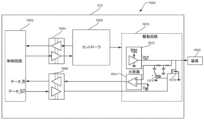
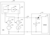
調整可能な入力電流及び電圧設定点、及び、電流を供給又はシンクするよう構成される出力を有する双方向電流源と、双方向電流源の出力を接地端子に短絡させるように構成される第一のスイッチと、双方向電流源の出力を電圧供給端子に短絡させるように構成される第二のスイッチと、電流源の出力に連結されたマルチプレクサであって、電流源と送受信機の差分データ線との間で切り替わるように構成されるマルチプレクサと、を備える、ハンドスイッチ回路。 a bidirectional current source having adjustable input current and voltage set points and an output configured to source or sink current; and a first configured to short the output of the bidirectional current source to a ground terminal. a second switch configured to short the output of the bidirectional current source to the voltage supply terminal, and a multiplexer coupled to the output of the current source, the differential data line between the current source and the transceiver. a multiplexer configured to switch between.
調整可能な入力電流及び電圧設定点、及び、電流を供給又はシンクするよう構成される出力を有する双方向電流源と、双方向電流源の出力を接地端子に短絡させるように構成される第一の半導体スイッチと、双方向電流源の出力を電圧供給端子に短絡させるように構成される第二の半導体スイッチと、電流源の出力に連結されたマルチプレクサであって、電流源と送受信機の差分データ線との間で切り替わるように構成されるマルチプレクサと、ハンドスイッチ回路に連結された制御回路と、ハンドスイッチ回路に連結された器具と、を備えるエネルギーモジュールであって、ハンドスイッチ回路が、単一のワイヤ上で複数の通信プロトコルを用いて外科用器具と通信するように構成されているエネルギーモジュール。 a bidirectional current source having adjustable input current and voltage set points and an output configured to source or sink current; and a first configured to short the output of the bidirectional current source to a ground terminal. a second semiconductor switch configured to short the output of the bidirectional current source to the voltage supply terminal, and a multiplexer coupled to the output of the current source, the multiplexer configured to short the output of the bidirectional current source to the voltage supply terminal; An energy module comprising a multiplexer configured to switch to and from a data line, a control circuit coupled to the handswitch circuit, and an appliance coupled to the handswitch circuit, the handswitch circuit comprising: An energy module configured to communicate with a surgical instrument using multiple communication protocols over a single wire.
構成及び操作方法の両方に関して本明細書で説明する様々な態様は、それらの他の目的及び利点とともに、以下の説明を以下の添付図面と併せて参照することで最良に理解され得る。
本出願の出願人は、各開示の全体が参照により本明細書に組み込まれる、同時に出願された以下の米国特許出願を所有する。
・「METHOD FOR CONSTRUCTING AND USING A MODULAR SURGICAL ENERGY SYSTEM WITH MULTIPLE DEVICES」と題する米国特許出願整理番号第END9067USNP1/180679-1M号、
・「METHOD FOR ENERGY DISTRIBUTION IN A SURGICAL MODULAR ENERGY SYSTEM」と題する米国特許出願整理番号第END9069USNP1/180681-1M号、
・「SURGICAL MODULAR ENERGY SYSTEM WITH A SEGMENTED BACKPLANE」と題する米国特許出願整理番号第END9069USNP2/180681-2号、
・「SURGICAL MODULAR ENERGY SYSTEM WITH FOOTER MODULE」と題する米国特許出願整理番号第END9069USNP3/180681-3号、
・「POWER AND COMMUNICATION MITIGATION ARRANGEMENT FOR MODULAR SURGICAL ENERGY SYSTEM」と題する米国特許出願整理番号END9069USNP4/180681-4号、
・「MODULAR SURGICAL ENERGY SYSTEM WITH MODULE POSITIONAL AWARENESS SENSING WITH VOLTAGE DETECTION」と題する米国特許出願整理番号第END9069USNP5/180681-5号、
・「MODULAR SURGICAL ENERGY SYSTEM WITH MODULE POSITIONAL AWARENESS SENSING WITH TIME COUNTER」と題する米国特許出願整理番号第END9069USNP6/180681-6号、
・「MODULAR SURGICAL ENERGY SYSTEM WITH MODULE POSITIONAL AWARENESS WITH DIGITAL LOGIC」と題する米国特許出願整理番号第END9069USNP7/180681-7号、
・「METHOD FOR CONTROLLING AN ENERGY MODULE OUTPUT」と題する米国特許出願整理番号第END9068USNP1/180680-1M号、
・「ENERGY MODULE FOR DRIVING MULTIPLE ENERGY MODALITIES」と題する米国特許出願整理番号第END9068USNP2/180680-2号、
・「GROUNDING ARRANGEMENT OF ENERGY MODULES」と題する米国特許出願整理番号第END9068USNP3/180680-3号、
・「BACKPLANE CONNECTOR DESIGN TO CONNECT STACKED ENERGY MODULES」と題する米国特許出願整理番号第END9068USNP4/180680-4号、
・「ENERGY MODULE FOR DRIVING MULTIPLE ENERGY MODALITIES THROUGH A PORT」と題する米国特許出願整理番号第END9068USNP5/180680-5号、
・「SURGICAL INSTRUMENT UTILIZING DRIVE SIGNAL TO POWER SECONDARY FUNCTION」と題する米国特許出願整理番号第END9068USNP6/180680-6号、
・「METHOD FOR CONTROLLING A MODULAR ENERGY SYSTEM USER INTERFACE」と題する米国特許出願整理番号第END9038USNP1/180529-1M号、
・「PASSIVE HEADER MODULE FOR A MODULAR ENERGY SYSTEM」と題する米国特許出願整理番号第END9038USNP2/180529-2号、
・「CONSOLIDATED USER INTERFACE FOR MODULAR ENERGY SYSTEM」と題する米国特許出願整理番号第END9038USNP3/180529-3号、
・「AUDIO TONE CONSTRUCTION FOR AN ENERGY MODULE OF A MODULAR ENERGY SYSTEM」と題する米国特許出願整理番号第END9038USNP4/180529-4号、
・「ADAPTABLY CONNECTABLE AND REASSIGNABLE SYSTEM ACCESSORIES FOR MODULAR ENERGY SYSTEM」と題する米国特許出願整理番号第END9038USNP5/180529-5号、
・「METHOD FOR COMMUNICATING BETWEEN MODULES AND DEVICES IN A MODULAR SURGICAL SYSTEM」と題する米国特許出願整理番号第END9070USNP1/180682-1M号、
・「FLEXIBLE HAND-SWITCH CIRCUIT」と題する米国特許出願整理番号第END9070USNP2/180682-2号、
・「FIRST AND SECOND COMMUNICATION PROTOCOL ARRANGEMENT FOR DRIVING PRIMARY AND SECONDARY DEVICES THROUGH A SINGLE PORT」と題する米国特許出願整理番号第END9070USNP3/180682-3号、
・「FLEXIBLE NEUTRAL ELECTRODE」と題する米国特許出願整理番号第END9070USNP4/180682-4号、
・「SMART RETURN PAD SENSING THROUGH MODULATION OF NEAR FIELD COMMUNICATION AND CONTACT QUALITY MONITORING SIGNALS」と題する米国特許出願整理番号第END9070USNP5/180682-5号、
・「AUTOMATIC ULTRASONIC ENERGY ACTIVATION CIRCUIT DESIGN FOR MODULAR SURGICAL SYSTEMS」と題する米国特許出願整理番号第END9070USNP6/180682-6号、
・「COORDINATED ENERGY OUTPUTS OF SEPARATE BUT CONNECTED MODULES」と題する米国特許出願整理番号第END9070USNP7/180682-7号、
・「MANAGING SIMULTANEOUS MONOPOLAR OUTPUTS USING DUTY CYCLE AND SYNCHRONIZATION」と題する米国特許出願整理番号第END9070USNP8/180682-8号、
・「PORT PRESENCE DETECTION SYSTEM FOR MODULAR ENERGY SYSTEM」と題する米国特許出願整理番号第END9070USNP9/180682-9号、
・「INSTRUMENT TRACKING ARRANGEMENT BASED ON REAL TIME CLOCK INFORMATION」と題する米国特許出願整理番号第END9070USNP10/180682-10号、
・「REGIONAL LOCATION TRACKING OF COMPONENTS OF A MODULAR ENERGY SYSTEM」と題する米国特許出願整理番号第END9070USNP11/180682-11号、
・「ENERGY MODULE」と題する米国特許出願整理番号第END9212USDP1/190370D号、
・「ENERGY MODULE MONOPOLAR PORT WITH FOURTH SOCKET AMONG THREE OTHER SOCKETS」と題する米国特許出願整理番号第END9213USDP1/190371D号、
・「BACKPLANE CONNECTOR FOR ENERGY MODULE」と題する米国特許出願整理番号第END9214USDP1/190372D号、及び
・「ALERT SCREEN FOR ENERGY MODULE」と題する米国特許出願整理番号第END9215USDP1/190373D号。 The applicant of this application owns the following concurrently filed US patent applications, each of which is incorporated herein by reference in its entirety.
- U.S. Patent Application Docket No. END9067USNP1/180679-1M entitled “METHOD FOR CONSTRUCTING AND USING A MODULAR SURGICAL ENERGY SYSTEM WITH MULTIPLE DEVICES” ,
- United States Patent Application Docket No. END9069USNP1/180681-1M entitled "METHOD FOR ENERGY DISTRIBUTION IN A SURGICAL MODULAR ENERGY SYSTEM";
- United States Patent Application Docket No. END9069USNP2/180681-2 entitled "SURGICAL MODULAR ENERGY SYSTEM WITH A SEGMENTED BACKPLANE";
- United States Patent Application Docket No. END9069USNP3/180681-3 entitled "SURGICAL MODULAR ENERGY SYSTEM WITH FOOTER MODULE";
- United States Patent Application Docket No. END9069USNP4/180681-4 entitled "POWER AND COMMUNICATION MITIGATION ARRANGEMENT FOR MODULAR SURGICAL ENERGY SYSTEM";
・U.S. Patent Application Docket No. END9069USNP5/1806 entitled “MODULAR SURGICAL ENERGY SYSTEM WITH MODULE POSITIONAL AWARENESS SENSING WITH VOLTAGE DETECTION” No. 81-5,
・U.S. Patent Application Docket No. END9069USNP6/180681-6 entitled “MODULAR SURGICAL ENERGY SYSTEM WITH MODULE POSITIONAL AWARENESS SENSING WITH TIME COUNTER” ,
- United States Patent Application Docket No. END9069USNP7/180681-7 entitled "MODULAR SURGICAL ENERGY SYSTEM WITH MODULE POSITIONAL AWARENESS WITH DIGITAL LOGIC";
- United States Patent Application Docket No. END9068USNP1/180680-1M entitled "METHOD FOR CONTROLLING AN ENERGY MODULE OUTPUT";
- United States Patent Application Docket No. END9068USNP2/180680-2 entitled "ENERGY MODULE FOR DRIVING MULTIPLE ENERGY MODALITIES";
- United States Patent Application Docket No. END9068USNP3/180680-3 entitled "GROUNDING ARRANGEMENT OF ENERGY MODULES";
- United States Patent Application Docket No. END9068USNP4/180680-4 entitled "BACKPLANE CONNECTOR DESIGN TO CONNECT STACKED ENERGY MODULES";
- United States Patent Application Docket No. END9068USNP5/180680-5 entitled "ENERGY MODULE FOR DRIVING MULTIPLE ENERGY MODALITIES THROUGH A PORT";
- United States Patent Application Docket No. END9068USNP6/180680-6 entitled "SURGICAL INSTRUMENT UTILIZING DRIVE SIGNAL TO POWER SECONDARY FUNCTION";
- United States Patent Application Docket No. END9038USNP1/180529-1M entitled "METHOD FOR CONTROLLING A MODULAR ENERGY SYSTEM USER INTERFACE";
- United States Patent Application Docket No. END9038USNP2/180529-2 entitled "PASSIVE HEADER MODULE FOR A MODULAR ENERGY SYSTEM";
- United States Patent Application Docket No. END9038USNP3/180529-3 entitled "CONSOLIDATED USER INTERFACE FOR MODULAR ENERGY SYSTEM";
- United States Patent Application Docket No. END9038USNP4/180529-4 entitled "AUDIO TONE CONSTRUCTION FOR AN ENERGY MODULE OF A MODULAR ENERGY SYSTEM";
- United States Patent Application Docket No. END9038USNP5/180529-5 entitled "ADAPTABLE CONNECTABLE AND REASSIGNABLE SYSTEM ACCESSORIES FOR MODULAR ENERGY SYSTEM";
- United States Patent Application Docket No. END9070USNP1/180682-1M entitled "METHOD FOR COMMUNICATION BETWEEN MODULES AND DEVICES IN A MODULAR SURGICAL SYSTEM";
- United States Patent Application Docket No. END9070USNP2/180682-2 entitled "FLEXIBLE HAND-SWITCH CIRCUIT";
・U.S. Patent entitled "FIRST AND SECOND COMMUNICATION PROTOCOL ARRANGMENT FOR DRIVING PRIMARY AND SECONDARY DEVICES THROUGH A SINGLE PORT" Application reference number END9070USNP3/180682-3,
- United States Patent Application Docket No. END9070USNP4/180682-4 entitled "FLEXIBLE NEUTRAL ELECTRODE";
- U.S. Patent Application Docket No. E entitled "SMART RETURN PAD SENSING THROUGH MODULATION OF NEAR FIELD COMMUNICATION AND CONTACT QUALITY MONITORING SIGNALS" ND9070USNP5/180682-5,
- United States Patent Application Docket No. END9070USNP6/180682-6 entitled "AUTOMATIC ULTRASONIC ENERGY ACTIVATION CIRCUIT DESIGN FOR MODULAR SURGICAL SYSTEMS";
- United States Patent Application Docket No. END9070USNP7/180682-7 entitled "COORDINATED ENERGY OUTPUTS OF SEPARATE BUT CONNECTED MODULES";
- United States Patent Application Docket No. END9070USNP8/180682-8 entitled "MANAGING SIMULTANEOUS MONOPOLAR OUTPUTS USING DUTY CYCLE AND SYNCHRONIZATION";
- United States Patent Application Docket No. END9070USNP9/180682-9 entitled "PORT PRESENCE DETECTION SYSTEM FOR MODULAR ENERGY SYSTEM";
- United States Patent Application Docket No. END9070USNP10/180682-10 entitled "INSTRUMENT TRACKING ARRANGEMENT BASED ON REAL TIME CLOCK INFORMATION";
- United States Patent Application Docket No. END9070USNP11/180682-11 entitled "REGIONAL LOCATION TRACKING OF COMPONENTS OF A MODULAR ENERGY SYSTEM";
- United States Patent Application Docket No. END9212USDP1/190370D entitled "ENERGY MODULE";
- United States Patent Application Docket No. END9213USDP1/190371D entitled "ENERGY MODULE MONOPOLAR PORT WITH FOURTH SOCKET AMONG THREE OTHER SOCKETS";
- U.S. Patent Application Docket No. END9214USDP1/190372D entitled "BACKPLANE CONNECTOR FOR ENERGY MODULE," and - U.S. Patent Application Docket No. END9215U entitled "ALERT SCREEN FOR ENERGY MODULE." SDP1/190373D.
外科用装置及び発生器の様々な態様を詳細に説明する前に、例示の実施例は、適用又は用途において、添付の図面及び説明で示される部品の構造及び配置の詳細に限定されないことに注意を喚起しておく。例示の実施例は、他の態様、変形形態、及び修正形態で実装されるか、又はそれらに組み込まれてもよく、様々な方法で実施又は実行されてもよい。更に、特に明記しない限り、本明細書で用いられる用語及び表現は、読者の便宜のために例示の実施例を説明する目的で選択されたものであり、それらを限定するためのものではない。更に、以下に記述される態様、態様の表現、及び/又は実施例のうち1つ又は2つ以上を、以下に記述される他の態様、態様の表現、及び/又は実施例のうち任意の1つ又は2つ以上と組み合わせることができるものと理解されたい。 Before describing various aspects of the surgical device and generator in detail, it is noted that the illustrative embodiments are not limited in application or use to the details of construction and arrangement of parts shown in the accompanying drawings and description. Arouse. The example embodiments may be implemented or incorporated into other aspects, variations, and modifications and may be practiced or carried out in various ways. Furthermore, unless otherwise stated, the terms and expressions used herein have been chosen for the convenience of the reader to describe the illustrative embodiments and are not intended to be limiting. Additionally, one or more of the aspects, expressions of aspects, and/or examples described below may be combined with any other aspects, expressions of aspects, and/or examples described below. It is to be understood that one or more may be combined.
様々な態様が、改善された超音波外科用装置、電気外科用装置、及びこれとともに使用するための発生器を対象とする。超音波外科用装置の態様は、例えば、外科処置中に組織を横切開及び/又は凝固するように構成され得る。電気外科用装置の態様は、例えば、外科処置中に、組織を横切開、凝固、スケーリング、溶接及び/又は乾燥させるように構成され得る。 Various aspects are directed to improved ultrasonic surgical devices, electrosurgical devices, and generators for use therewith. Aspects of the ultrasonic surgical device may be configured, for example, to transect and/or coagulate tissue during a surgical procedure. Aspects of the electrosurgical device may be configured, for example, to transect, coagulate, scale, weld, and/or dry tissue during a surgical procedure.
外科システムのハードウェア
図1を参照すると、コンピュータ実装インタラクティブ外科システム100は、1つ又は2つ以上の外科システム102と、クラウドベースのシステム(例えば、ストレージ装置105に連結されたリモートサーバ113を含むことができるクラウド104)と、を含む。各外科システム102は、リモートサーバ113を含み得るクラウド104と通信する、少なくとも1つの外科用ハブ106を含む。一実施例では、図1に示すように、外科システム102は、互いに、及び/又はハブ106と通信するように構成された、可視化システム108と、ロボットシステム110と、ハンドヘルド式インテリジェント外科用器具112と、を含む。いくつかの態様では、外科システム102は、M個のハブ106と、N個の可視化システム108と、O個のロボットシステム110と、P個のハンドヘルド式インテリジェント外科用器具112と、を含んでもよく、ここでM、N、O及びPは1以上の整数である。 Surgical System Hardware Referring to FIG. 1, a computer-implemented interactive
図2は、外科手術室116内の手術台114上に横たわる患者に対して外科処置を実施するために使用される外科システム102の一例を示す。ロボットシステム110は、外科処置において外科システム102の一部として使用される。ロボットシステム110は、外科医のコンソール118と、患者側カート120(外科用ロボット)と、外科用ロボットハブ122と、を含む。外科医が外科医のコンソール118を介して手術部位を見る間、患者側カート120は、患者の身体の低侵襲切開部を介して、少なくとも1つの取り外し可能に連結された外科用ツール117を操作することができる。手術部位の画像は医療用撮像装置124によって得ることができ、医療用撮像装置124は、患者側カート120によって操作され、撮像装置124を向けさせ得る。ロボットハブ122は、手術部位の画像を処理し、その後処理した画像を外科医のコンソール118を介して外科医に対して表示させるために使用することができる。 FIG. 2 illustrates an example of a
他のタイプのロボットシステムを、外科システム102とともに使用するために容易に適合させることができる。本開示とともに使用するのに好適なロボットシステム及び外科用ツールの様々な例は、その開示全体が参照により本明細書に組み込まれる、2017年12月28日出願の「ROBOT ASSISTED SURGICAL PLATFORM」と題する米国仮特許出願第62/611,339号に記載されている。 Other types of robotic systems can be easily adapted for use with
クラウド104によって実施され、本開示とともに使用するのに好適なクラウドベース分析法の様々な例は、その開示全体が参照により本明細書に組み込まれる、2017年12月28日出願の「CLOUD-BASED MEDICAL ANALYTICS」と題する米国仮特許出願第62/611,340号に記載されている。 Various examples of cloud-based analysis methods implemented by
様々な態様では、撮像装置124は、少なくとも1つの画像センサと、1つ若しくは2つ以上の光学構成要素と、を含む。好適な画像センサとしては、電荷結合素子(Charge-Coupled Device、CCD)センサ及び相補型金属酸化膜半導体(Complementary Metal-Oxide Semiconductor、CMOS)センサが挙げられるが、これらに限定されない。 In various aspects, imaging device 124 includes at least one image sensor and one or more optical components. Suitable image sensors include, but are not limited to, charge-coupled device (CCD) sensors and complementary metal-oxide semiconductor (CMOS) sensors.
撮像装置124の光学構成要素は、1つ若しくは2つ以上の照明光源及び/又は1つ若しくは2つ以上のレンズを含んでもよい。1つ若しくは2つ以上の照明光源は、手術野の一部を照明するように方向付けられてもよい。1つ若しくは2つ以上の画像センサは、組織及び/又は外科用器具から反射又は屈折された光を含む、手術野から反射又は屈折された光を受光することができる。 Optical components of imager 124 may include one or more illumination sources and/or one or more lenses. One or more illumination sources may be directed to illuminate a portion of the surgical field. The one or more image sensors can receive light reflected or refracted from the surgical field, including light reflected or refracted from tissue and/or surgical instruments.
1つ若しくは2つ以上の照明光源は、可視スペクトル及び不可視スペクトル内の電磁エネルギーを放射するように構成され得る。光学スペクトル又は発光スペクトルと称されることもある可視スペクトルは、人間の目に可視の(すなわち、人間の目で検出可能な)電磁スペクトルの一部分であり、可視光、又は単に光と称されることがある。典型的な人間の目は、空気中の約380nm~約750nmの波長に反応する。 The one or more illumination sources may be configured to emit electromagnetic energy within the visible and invisible spectrum. The visible spectrum, sometimes referred to as the optical spectrum or the emission spectrum, is the portion of the electromagnetic spectrum that is visible to the human eye (i.e., detectable by the human eye) and is referred to as visible light, or simply light. Sometimes. The typical human eye is sensitive to wavelengths from about 380 nm to about 750 nm in air.
不可視スペクトル(すなわち、非発光スペクトル)は、可視スペクトルの下方及び上方に位置する(すなわち、約380nm未満及び約750nm超の波長の)電磁スペクトルの一部分である。不可視スペクトルは、人間の目で検出可能ではない。約750nmを超える波長は、赤色可視スペクトルよりも長く、これらは不可視赤外線(IR)、マイクロ波及び無線電磁放射線になる。約380nm未満の波長は、紫色スペクトルよりも短く、これらは不可視紫外線、X線及びガンマ線電磁放射線になる。 The invisible spectrum (ie, the non-emissive spectrum) is the portion of the electromagnetic spectrum that lies below and above the visible spectrum (ie, at wavelengths less than about 380 nm and greater than about 750 nm). Invisible spectrum is not detectable by the human eye. Wavelengths above about 750 nm are longer than the red visible spectrum, and these become invisible infrared (IR), microwave and wireless electromagnetic radiation. Wavelengths below about 380 nm are shorter than the violet spectrum, and these constitute invisible ultraviolet, X-ray, and gamma electromagnetic radiation.
様々な態様では、撮像装置124は、低侵襲性手術で使用するように構成されている。本開示とともに使用するのに好適な撮像装置の例としては、関節鏡、血管鏡、気管支鏡、胆道鏡、結腸鏡、膀胱鏡、十二指腸鏡、腸鏡、食道胃十二指腸鏡(胃鏡)、内視鏡、喉頭鏡、鼻咽喉-腎盂鏡(nasopharyngo-neproscope)、S状結腸鏡、胸腔鏡、及び尿管鏡が挙げられるが、これらに限定されない。 In various aspects, imaging device 124 is configured for use in minimally invasive surgery. Examples of imaging devices suitable for use with the present disclosure include arthroscopes, angioscopes, bronchoscopes, choloscopes, colonoscopes, cystoscopes, duodenoscopes, enteroscopes, esophagogastroduodenoscopes (gastroscopes), endoscopes, etc. Speculums include, but are not limited to, laryngoscopes, nasopharyngo-neproscopes, sigmoidoscopes, thoracoscopes, and ureteroscopes.
一態様では、撮像装置は、トポグラフィーと下層構造とを区別するためにマルチスペクトルモニタリングを用いる。マルチスペクトル画像は、電磁スペクトル全体から特定の波長範囲内の画像データを取り込むものである。波長は、フィルタによって、又は可視光範囲を超える周波数、例えば、IR及び紫外光を含む特定の波長の光を感知できる器具を使用することによって分離することができる。スペクトル撮像法は、人間の目がその赤色、緑色及び青色の受容体で捕捉することのできない追加情報の抽出を可能にすることができる。マルチスペクトル撮像法の使用は、その開示全体が参照により本明細書に組み込まれる2017年12月28日出願の「INTERACTIVE SURGICAL PLATFORM」と題する米国仮特許出願第62/611,341号の「Advanced Imaging Acquisition Module」の項で詳細に説明されている。マルチスペクトルモニタリングは、治療される組織上で上述の試験の1つ又は2つ以上を実施するため、外科的タスクが完了した後に手術野を再配置するのに有用なツールであり得る。 In one aspect, the imaging device uses multispectral monitoring to distinguish between topography and underlying structure. Multispectral images capture image data within specific wavelength ranges from across the electromagnetic spectrum. Wavelengths can be separated by filters or by using instruments that are sensitive to specific wavelengths of light, including frequencies beyond the visible light range, such as IR and ultraviolet light. Spectral imaging can enable the extraction of additional information that the human eye cannot capture with its red, green, and blue receptors. The use of multispectral imaging techniques is described in "Advanced Imaging" in U.S. Provisional Patent Application No. 62/611,341, entitled "INTERACTIVE SURGICAL PLATFORM," filed December 28, 2017, the entire disclosure of which is incorporated herein by reference. Acquisition Module” section. Multispectral monitoring can be a useful tool for repositioning the surgical field after a surgical task is completed to perform one or more of the above-mentioned tests on the tissue being treated.
いかなる外科手術においても手術室及び外科用設備の厳格な滅菌が必要であることは自明である。「外科施術の行われる現場(surgical theater)」、すなわち手術室(operating room)又は処置室(treatment room)に必要とされる厳格な衛生及び滅菌条件は、全ての医療装置及び設備の最大級の滅菌性を必要とする。上記の滅菌プロセスの一部としては、患者と接触する、又は滅菌野に侵入するあらゆるもの(撮像装置124並びにその付属品及び構成要素を含む)を滅菌する必要が挙げられる。滅菌野は、トレイ内若しくは滅菌タオル上などの微生物を含まないと見なされる特定の領域と見なされ得ること、又は滅菌野は、外科処置のために準備された患者のすぐ周囲の領域と見なされ得ることは理解されよう。滅菌野は、適切な衣類を着用した洗浄済みのチーム構成員、並びにその領域内の全ての備品及び固定具を含み得る。 It is self-evident that any surgical procedure requires rigorous sterilization of the operating room and surgical equipment. The strict hygiene and sterilization conditions required in the "surgical theater", i.e. the operating room or treatment room, are the highest standards for all medical equipment and equipment. Requires sterility. Part of the sterilization process described above includes the need to sterilize anything that comes into contact with the patient or enters the sterilization field, including the imaging device 124 and its accessories and components. A sterile field may be considered a specific area that is considered free of microorganisms, such as in a tray or on a sterile towel, or a sterile field may be considered the area immediately surrounding a patient prepared for a surgical procedure. You will understand what you get. A sterile field may include cleaned team members wearing appropriate clothing and all equipment and fixtures within the area.
様々な態様では、可視化システム108は、図2に示されるように、滅菌野に対して戦略的に配置される1つ又は2つ以上の撮像センサと、1つ又は2つ以上の画像処理ユニットと、1つ又は2つ以上のストレージアレイと、1つ又は2つ以上のディスプレイと、を含む。一態様では、可視化システム108は、HL7、PACS及びEMRのインターフェースを含む。可視化システム108の様々な構成要素については、その開示全体が参照により本明細書に組み込まれる2017年12月28日出願の「INTERACTIVE SURGICAL PLATFORM」と題する米国仮特許出願第62/611,341号の「Advanced Imaging Acquisition Module」の項で説明されている。 In various aspects,
図2に示すように、一次ディスプレイ119は、手術台114に位置するオペレータに可視であるように滅菌野内に位置付けされる。加えて、可視化タワー111が、滅菌野の外に位置付けされる。可視化タワー111は、互いに離れる方に面する第1の非滅菌ディスプレイ107及び第2の非滅菌ディスプレイ109を含む。ハブ106によって誘導される可視化システム108は、ディスプレイ107、109及び119を利用して、滅菌野の内側及び外側のオペレータに対する情報フローを調整するように構成されている。例えば、ハブ106は、可視化システム108に一次ディスプレイ119上の手術部位のライブ映像を維持させながら、撮像装置124によって記録される手術部位のスナップショットを非滅菌ディスプレイ107又は109上に表示させることができる。非滅菌ディスプレイ107又は109上のスナップショットは、例えば、非滅菌オペレータにより、外科処置に関連する診断ステップを実施可能とすることができる。 As shown in FIG. 2,
一態様では、ハブ106は、滅菌野内で、可視化タワー111にある非滅菌オペレータによって入力された診断入力又はフィードバックを滅菌領域内の一次ディスプレイ119に送り、これを手術台に位置する滅菌オペレータが見ることができるようにも構成されている。一実施例では、入力は、ハブ106によって一次ディスプレイ119に送ることのできる、非滅菌ディスプレイ107又は109上に表示されるスナップショットに対する修正の形態であってもよい。 In one aspect, the
図2を参照すると、外科用器具112は、外科処置において外科システム102の一部として使用されている。ハブ106はまた、外科用器具112のディスプレイへの情報フローを調整するようにも構成されている。例えば、その開示全体が参照により本明細書に組み込まれる、「INTERACTIVE SURGICAL PLATFORM」と題する2017年12月28日出願の米国仮特許出願第62/611,341号における。可視化タワー111にある非滅菌オペレータによって入力される診断入力又はフィードバックは、ハブ106によって滅菌野内の外科用器具ディスプレイ115に送られ得、ここで診断入力又はフィードバックを、外科用器具112のオペレータが見ることができる。外科システム102とともに使用するのに好適な例示的な外科用器具については、例えば、「外科用器具のハードウェア(SURGICAL INSTRUMENT HARDWARE)」の項で、及びその開示全体が参照により本明細書に組み込まれる「INTERACTIVE SURGICAL PLATFORM」と題する2017年12月28日出願の米国特許仮出願第62/611,341号で説明されている。 Referring to FIG. 2,
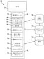
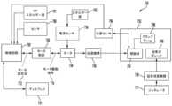
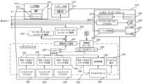
ここで図3を参照すると、可視化システム108、ロボットシステム110及びハンドヘルド式インテリジェント外科用器具112と通信するハブ106が示されている。ハブ106は、ハブディスプレイ135、撮像モジュール138、発生器モジュール140、通信モジュール130、プロセッサモジュール132、及びストレージアレイ134を含む。特定の態様では、図3に示すように、ハブ106は、排煙モジュール126及び/又は吸引/灌注モジュール128を更に含む。 Referring now to FIG. 3, a
外科処置中、封止及び/又は切断のために、組織へのエネルギー印加することには、一般に、排煙、過剰な流体の吸引、及び/又は組織の灌注と関連付けられる。異なる供給源からの流体ライン、電力ライン及び/又はデータラインは、外科処置中に絡まり合うことが多い。外科処置中にこの問題に対処することで貴重な時間が失われる場合がある。ラインの絡まりをほどくには、それらの対応するモジュールからラインを抜くことが必要となる場合があり、そのためにはモジュールをリセットすることが必要となる場合がある。ハブのモジュール式エンクロージャ136は、電力ライン、データライン、及び流体ラインを管理するための統一環境を提供し、このようなライン間の絡まりの頻度を低減させる。 During surgical procedures, applying energy to tissue for sealing and/or cutting is commonly associated with evacuation of smoke, aspiration of excess fluid, and/or irrigation of the tissue. Fluid lines, power lines and/or data lines from different sources often become intertwined during surgical procedures. Valuable time may be lost addressing this problem during the surgical procedure. Disentangling the lines may require removing the lines from their corresponding modules, which may require resetting the modules. The hub's
本開示の態様は、手術部位における組織へのエネルギー印加を伴う外科処置において使用するための外科用ハブを提示する。外科用ハブは、ハブエンクロージャと、ハブエンクロージャのドッキングステーション内に摺動可能に受容可能な組み合わせ発生器モジュールと、を含む。ドッキングステーションはデータ接点及び電力接点を含む。組み合わせ発生器モジュールは、単一ユニット内に収容された、超音波エネルギー発生器構成要素、双極RFエネルギー発生器構成要素、及び単極RFエネルギー発生器構成要素のうちの2つ又は3つ以上を含む。一態様では、組み合わせ発生器モジュールはまた、排煙構成要素と、組み合わせ発生器モジュールを外科用器具に接続するための少なくとも1つのエネルギー供給ケーブルと、組織への治療エネルギーの印加によって発生した煙、流体及び/又は微粒子を排出するように構成された少なくとも1つの排煙構成要素と、遠隔手術部位から排煙構成要素まで延在する流体ラインと、を含む。 Aspects of the present disclosure present a surgical hub for use in surgical procedures involving the application of energy to tissue at a surgical site. The surgical hub includes a hub enclosure and a combination generator module slidably receivable within a docking station of the hub enclosure. The docking station includes data contacts and power contacts. A combination generator module includes two or more of the following: an ultrasonic energy generator component, a bipolar RF energy generator component, and a monopolar RF energy generator component housed within a single unit. include. In one aspect, the combination generator module also includes a smoke evacuation component, at least one energy delivery cable for connecting the combination generator module to a surgical instrument, and smoke generated by application of therapeutic energy to tissue. at least one smoke evacuation component configured to expel fluid and/or particulates; and a fluid line extending from the remote surgical site to the smoke evacuation component.
一態様では、上記の流体ラインは第1の流体ラインであり、第2の流体ラインは、遠隔手術部位から、ハブエンクロージャ内に摺動可能に受容される吸引及び灌注モジュールまで延在している。一態様では、ハブエンクロージャは、流体インターフェースを備える。 In one aspect, the fluid line is a first fluid line and the second fluid line extends from the remote surgical site to an aspiration and irrigation module slidably received within the hub enclosure. . In one aspect, the hub enclosure includes a fluidic interface.
特定の外科処置は、2つ以上のエネルギータイプを組織に印加することを必要とする場合がある。1つのエネルギータイプは、組織を切断するのにより有益であり得るが、別の異なるエネルギータイプは、組織を封止するのにより有益であり得る。例えば、双極発生器は組織を封止するために使用することができ、一方で、超音波発生器は封止された組織を切断するために使用することができる。本開示の態様は、ハブのモジュール式エンクロージャ136が様々な発生器を収容して、これらの間のインタラクティブ通信を促進するように構成されているという解決法を提示する。ハブのモジュール式エンクロージャ136の利点の1つは、様々なモジュールの迅速な取り外し及び/又は交換を可能にすることである。 Certain surgical procedures may require the application of more than one type of energy to tissue. One energy type may be more beneficial for cutting tissue, while another different energy type may be more beneficial for sealing tissue. For example, a bipolar generator can be used to seal tissue, while an ultrasound generator can be used to cut the sealed tissue. Aspects of the present disclosure present a solution in which the hub's
本開示の態様は、組織へのエネルギー印加を伴う外科処置で使用するためのモジュール式外科用エンクロージャを提示する。モジュール式外科用エンクロージャは、組織に印加するための第1のエネルギーを発生させるように構成された第1のエネルギー発生器モジュールと、第1のデータ及び電力接点を含む第1のドッキングポートを備える第1のドッキングステーションと、を含み、第1のエネルギー発生器モジュールは、電力及びデータ接点と電気係合するように摺動可能に移動可能であり、また第1のエネルギー発生器モジュールは、第1の電力及びデータ接点との電気係合から外れるように摺動可能に移動可能である。 Aspects of the present disclosure present a modular surgical enclosure for use in surgical procedures involving the application of energy to tissue. The modular surgical enclosure includes a first energy generator module configured to generate a first energy for application to tissue and a first docking port including first data and power contacts. a first docking station, the first energy generator module being slidably movable into electrical engagement with the power and data contacts, and the first energy generator module being slidably movable into electrical engagement with the power and data contacts; 1 and is slidably movable out of electrical engagement with one power and data contact.
上記に加えて、モジュール式外科用エンクロージャはまた、第1のエネルギーとは異なる、組織に印加するための第2のエネルギーを発生させるように構成された第2のエネルギー発生器モジュールと、第2のデータ及び電力接点を含む第2のドッキングポートを備える第2のドッキングステーションと、を含み、第2のエネルギー発生器モジュールは、電力及びデータ接点と電気係合するように摺動可能に移動可能であり、また第2のエネルギー発生器モジュールは、第2の電力及びデータ接点との電気係合から外れるように摺動可能に移動可能である。 In addition to the above, the modular surgical enclosure also includes a second energy generator module configured to generate a second energy for applying to tissue that is different than the first energy; a second docking station with a second docking port including data and power contacts, the second energy generator module being slidably movable into electrical engagement with the power and data contacts. and the second energy generator module is slidably moveable out of electrical engagement with the second power and data contacts.
加えて、モジュール式外科用エンクロージャはまた、第1のエネルギー発生器モジュールと第2のエネルギー発生器モジュールとの間の通信を容易にするように構成された、第1のドッキングポートと第2のドッキングポートとの間の通信バスを含む。 Additionally, the modular surgical enclosure also includes a first docking port and a second energy generator module configured to facilitate communication between the first energy generator module and the second energy generator module. Contains a communication bus to and from the docking port.
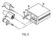
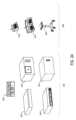
図3~図7を参照すると、発生器モジュール140と、排煙モジュール126と、吸引/灌注モジュール128との、モジュール式統合を可能にするハブのモジュール式エンクロージャ136に関する本開示の態様が提示される。ハブのモジュール式エンクロージャ136は、モジュール140とモジュール126とモジュール128と間のインタラクティブ通信を更に促進する。図5に示すように、発生器モジュール140は、ハブのモジュール式エンクロージャ136に摺動可能に挿入可能な単一のハウジングユニット139内に支持される、一体化された単極構成要素、双極構成要素及び超音波構成要素を備える発生器モジュールであってもよい。図5に示すように、発生器モジュール140は、単極装置146、双極装置147、及び超音波装置148に接続するように構成することができる。代替的に、発生器モジュール140は、ハブのモジュール式エンクロージャ136を介して相互作用する一連の単極、双極発生器モジュール及び/又は超音波発生器モジュールを備えてもよい。ハブのモジュール式エンクロージャ136は、複数の発生器が単一の発生器として機能するように、複数の発生器の挿入と、ハブのモジュール式エンクロージャ136にドッキングされた発生器間のインタラクティブ通信と、を促進するように構成されてもよい。 3-7, aspects of the present disclosure are presented relating to a hub
一態様では、ハブのモジュール式エンクロージャ136は、モジュール140、126、128の取り外し可能な取り付け及びそれらの間のインタラクティブ通信を可能にするために、外部及び無線通信ヘッダを備えるモジュール式電力及び通信バックプレーン149を備える。 In one aspect, the hub
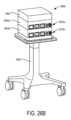
一態様では、ハブのモジュール式エンクロージャ136は、モジュール140、126、128を摺動可能に受容するように構成された、本明細書ではドロアーとも称されるドッキングステーション又はドロアー151を含む。図4は、外科用ハブエンクロージャ136、及び外科用ハブエンクロージャ136のドッキングステーション151に摺動可能に受容可能な組み合わせ発生器モジュール145の部分斜視図を示す。組み合わせ発生器モジュール145の後側には、電力及びデータ接点を有するドッキングポート152があり、そのドッキングポート152は、組み合わせ発生器モジュール145がハブのモジュール式エンクロージャ136の対応するドッキングステーション151内の所定の位置へと摺動されると、ハブのモジュール式エンクロージャ136の対応するドッキングステーション151の、電力及びデータ接点を有する対応するドッキングポート150と係合するように構成されている。一態様では、組み合わせ発生器モジュール145は、図5に示すように、単一のハウジングユニット139内に一緒に統合された、双極、超音波及び単極モジュールと、排煙モジュールと、を含む。 In one aspect, the hub
様々な態様では、排煙モジュール126は、捕捉/回収された煙及び/又は流体を手術部位から遠ざけ、例えば、排煙モジュール126へと搬送する、流体ライン154を含む。排煙モジュール126から発生する真空吸引は、煙を手術部位のユーティリティ導管の開口部に引き込むことができる。流体ラインに連結されたユーティリティ導管は、排煙モジュール126で終端する可撓管の形態であってもよい。ユーティリティ導管及び流体ラインは、ハブエンクロージャ136内に受容される排煙モジュール126に向かって延在する流体経路を画定する。 In various aspects, the
様々な態様では、吸引/灌注モジュール128は、吸い込み流体ライン及び吸引流体ラインを含む外科用ツールに連結されている。一実施例では、吸い込み及び吸引流体ラインは、手術部位から吸引/灌注モジュール128に向かって延在する可撓管の形態である。1つ又は2つ以上の駆動システムは、手術部位への、及び手術部位に対する流体の灌注及び吸い込みを引き起こすように構成され得る。 In various aspects, the suction/
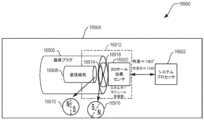
一態様では、外科用ツールは、その遠位端にエンドエフェクタを有しかつエンドエフェクタに関連付けられた少なくとも1つのエネルギー処置部を有するシャフトと、吸い込み管と、灌注管と、を含む。吸い込み管は、その遠位端に入口ポートを有することができ、吸い込み管はシャフトを通って延在する。同様に、灌注管はシャフトを通って延在することができ、かつエネルギー送達器具に近接した入口ポートを有することができる。エネルギー送達器具は、超音波エネルギー及び/又はRFエネルギーを手術部位に送達するように構成されており、最初にシャフトを通って延在するケーブルによって発生器モジュール140に連結されている。 In one aspect, a surgical tool includes a shaft having an end effector at a distal end thereof and at least one energy treatment portion associated with the end effector, a suction tube, and an irrigation tube. The suction tube can have an inlet port at its distal end, and the suction tube extends through the shaft. Similarly, an irrigation tube can extend through the shaft and have an entry port proximate to the energy delivery device. The energy delivery instrument is configured to deliver ultrasound and/or RF energy to the surgical site and is initially coupled to the
灌注管は流体源と流体連通することができ、吸い込み管は真空源と流体連通することができる。流体源及び/又は真空源は、吸引/灌注モジュール128内に収容され得る。一実施例では、流体源及び/又は真空源は、吸引/灌注モジュール128とは別に、ハブエンクロージャ136内に収容され得る。このような例では、流体インターフェースが、吸引/灌注モジュール128を流体源及び/又は真空源に接続するように構成され得る。 The irrigation tube can be in fluid communication with a fluid source and the suction tube can be in fluid communication with a vacuum source. A fluid source and/or a vacuum source may be housed within the aspiration/
一態様では、モジュール140、126、128、及び/又はハブのモジュール式エンクロージャ136上のそれらの対応するドッキングステーションは、モジュールのドッキングポートを位置合わせして、ハブのモジュール式エンクロージャ136のドッキングステーション内のこれらの対応部品と係合させるように構成された位置合わせ機構を含み得る。例えば、図4に示すように、組み合わせ発生器モジュール145は、側部ブラケット155を含み、その側部ブラケット155は、ハブのモジュール式エンクロージャ136の対応するドッキングステーション151の対応するブラケット156と摺動可能に係合するように構成されている。上記の複数のブラケットは協働して、組み合わせ発生器モジュール145のドッキングポート接点をハブのモジュール式エンクロージャ136のドッキングポート接点と電気的に係合させるように誘導する。 In one aspect, the
いくつかの態様では、ハブのモジュール式エンクロージャ136のドロアー151は、サイズが同じ又は実質的に同じであり、モジュールはドロアー151内に受容されるサイズに調整される。例えば、側部ブラケット155及び/又は156は、モジュールのサイズに応じてより大きくなっても小さくなってもよい。他の態様では、ドロアー151どうしは互いにサイズが異なり、各々特定のモジュールを収容するように設計される。 In some aspects, the
更に、適合しない接点を備えるドロアーにモジュールを挿入することを避けるため、特定のモジュールの接点を特定のドロアーの接点と係合するように、キー構造を設けてもよい。 Additionally, keying structures may be provided to engage the contacts of a particular module with the contacts of a particular drawer to avoid inserting a module into a drawer with incompatible contacts.
図4に示すように、1つのドロアー151のドッキングポート150は、通信リンク157を介して別のドロアー151のドッキングポート150に連結されて、ハブのモジュール式エンクロージャ136内に収容されたモジュール間のインタラクティブ通信を容易にすることができる。代替的又は追加的に、ハブのモジュール式エンクロージャ136のドッキングポート150は、ハブのモジュール式エンクロージャ136内に収容されたモジュール間の無線インタラクティブ通信を容易にしてもよい。例えば、Air Titan-Bluetoothなどの任意の好適な無線通信を用いてもよい。 As shown in FIG. 4, the
図6は、外科用ハブ206の複数のモジュールを受容するように構成された横方向モジュール式ハウジング160の複数の横方向ドッキングポートの個々の電力バスアタッチメントを示す。横方向モジュール式ハウジング160は、モジュール161を横方向に受容して相互接続するように構成されている。モジュール161は、モジュール161を相互接続するためのバックプレーンを含む横方向モジュール式ハウジング160のドッキングステーション162内に摺動可能に挿入されている。図6に示すように、モジュール161は、横方向モジュール式ハウジング160内で横方向に配置されている。代替的に、モジュール161は、横方向モジュール式ハウジング内で垂直方向に配置されてもよい。 FIG. 6 illustrates individual power bus attachments of a plurality of lateral docking ports of a lateral
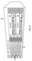
図7は、外科用ハブ106の複数のモジュール165を受容するように構成された垂直モジュール式ハウジング164を示す。モジュール165は、モジュール165を相互接続するためのバックプレーンを含む垂直モジュール式ハウジング164のドッキングステーション又はドロアー167内に摺動可能に挿入されている。垂直モジュール式ハウジング164のドロアー167は垂直方向に配置されているが、特定の場合では、垂直モジュール式ハウジング164は、横方向に配置されたドロアーを含んでもよい。更に、モジュール165は、垂直モジュール式ハウジング164のドッキングポートを介して互いに相互作用し得る。図7の実施例では、モジュール165の動作に関連するデータを表示するためのディスプレイ177が提供される。加えて、垂直モジュール式ハウジング164は、マスタモジュール178を含み、マスタモジュール178は、マスタモジュール178内に摺動可能に受容される複数のサブモジュールを収容する。 FIG. 7 shows a vertical
様々な態様では、撮像モジュール138は、内蔵型のビデオプロセッサ及びモジュール式光源を備え、様々な撮像装置とともに使用するように適合されている。一態様では、撮像装置は、光源モジュール及びカメラモジュールとともに組み立てることが可能なモジュール式ハウジングで構成されている。ハウジングは、使い捨て式ハウジングであってもよい。少なくとも1つの例では、使い捨て式ハウジングは、再利用可能なコントローラ、光源モジュール、及びカメラモジュールと取り外し可能に連結されている。光源モジュール及び/又はカメラモジュールは、外科処置のタイプに応じて選択的に選択することができる。一態様では、カメラモジュールはCCDセンサを含む。別の態様では、カメラモジュールはCMOSセンサを含む。別の態様では、カメラモジュールはビーム走査式撮像用に構成されている。同様に、光源モジュールは、外科処置に応じて白色光又は異なる光を送達するように構成することができる。 In various aspects, the
外科処置中に、手術野から外科用装置を除去して異なるカメラ又は異なる光源を含む別の外科用装置と交換することは非効率的であり得る。手術野の視野を一時的に喪失することは、望ましくない結果をもたらし得る。本開示のモジュール式撮像装置は、手術野から撮像装置を除去する必要なく、外科処置中に光源モジュール又はカメラモジュール中間体(midstream)の交換を可能にするように構成されている。 During a surgical procedure, it can be inefficient to remove a surgical device from the surgical field and replace it with another surgical device that includes a different camera or a different light source. Temporary loss of vision of the surgical field can have undesirable consequences. The modular imaging device of the present disclosure is configured to allow replacement of the light source module or camera module midstream during a surgical procedure without the need to remove the imaging device from the surgical field.
一態様では、撮像装置は、複数のチャネルを含む管状ハウジングを備える。第1のチャネルは、第1のチャネルとスナップ嵌め係合するように構成され得るカメラモジュールを摺動可能に受容するように構成されている。第2のチャネルは、第2のチャネルとスナップ嵌め係合するように構成され得る光源モジュールを摺動可能に受容するように構成されている。別の例では、カメラモジュール及び/又は光源モジュールは、これらの対応するチャネル内の最終位置へと回転させることができる。スナップ嵌め係合の代わりにねじ係合が用いられてもよい。 In one aspect, an imaging device includes a tubular housing that includes a plurality of channels. The first channel is configured to slidably receive a camera module that can be configured for snap-fit engagement with the first channel. The second channel is configured to slidably receive a light source module that can be configured to snap-fit into engagement with the second channel. In another example, the camera module and/or light source module can be rotated to a final position within their corresponding channels. A threaded engagement may be used instead of a snap-fit engagement.
様々な実施例では、複数の撮像装置が、複数の視野を提供するために手術野内の様々な位置に配置される。撮像モジュール138は、最適な視野を提供するために撮像装置間を切り替えるように構成することができる。様々な態様では、撮像モジュール138は、異なる撮像装置からの画像を統合するように構成することができる。 In various embodiments, multiple imaging devices are placed at various locations within the surgical field to provide multiple views.
本開示とともに使用するのに好適な様々な画像プロセッサ及び撮像装置は、その全体が参照により本明細書に組み込まれる「COMBINED SBI AND CONVENTIONAL IMAGE PROCESSOR」と題する2011年8月9日発行の米国特許第7,995,045号に記載されている。加えて、その全体が参照により本明細書に組み込まれる「SBI MOTION ARTIFACT REMOVAL APPARATUS AND METHOD」と題する2011年7月19日発行の米国特許第7,982,776号は、画像データからモーションアーチファクトを除去するための様々なシステムについて記載している。こうしたシステムは、撮像モジュール138と一体化され得る。更に、「CONTROLLABLE MAGNETIC SOURCE TO FIXTURE INTRACORPOREAL APPARATUS」と題する2011年12月15日公開の米国特許出願公開第2011/0306840号、及び「SYSTEM FOR PERFORMING A MINIMALLY INVASIVE SURGICAL PROCEDURE」と題する2014年8月28日公開の米国特許出願公開第2014/0243597号は、各々その全体が参照により本明細書に組み込まれる。 Various image processors and imaging devices suitable for use with the present disclosure are described in U.S. Pat. No. 7,995,045. Additionally, U.S. Pat. Various systems for removal are described. Such a system may be integrated with
図8は、医療施設の1つ又は2つ以上の手術室、又は外科手術のための専門設備を備えた医療施設内の任意の部屋に位置するモジュール式装置をクラウドベースのシステム(例えばストレージ装置205に連結されたリモートサーバ213を含み得るクラウド204)に接続するように構成されたモジュール式通信ハブ203を備える外科用データネットワーク201を示す。一態様では、モジュール式通信ハブ203は、ネットワークルータと通信するネットワークハブ207及び/又はネットワークスイッチ209を備える。モジュール式通信ハブ203はまた、ローカルコンピュータシステム210に連結することができ、ローカルコンピュータ処理及びデータ操作を提供することができる。外科用データネットワーク201は、受動的、インテリジェント又は切り替え式として構成されてもよい。受動的外科用データネットワークはデータの導管として機能し、データが1つの装置(又はセグメント)から別の装置(又はセグメント)に、及びクラウドコンピューティングリソースに行くことを可能にする。インテリジェント外科用データネットワークは、トラフィックが監視対象の外科用データネットワークを通過することを可能にし、ネットワークハブ207又はネットワークスイッチ209内の各ポートを構成する追加の機構を含む。インテリジェント外科用データネットワークは、管理可能なハブ又はスイッチと称され得る。スイッチングハブは、各パケットの宛先アドレスを読み取り、次いでパケットを正しいポートに転送する。 FIG. 8 shows a cloud-based system (e.g., storage device 205 shows a
手術室に位置するモジュール式装置1a~1nは、モジュール式通信ハブ203に連結されてもよい。ネットワークハブ207及び/又はネットワークスイッチ209は、ネットワークルータ211に連結されて、装置1a~1nをクラウド204又はローカルコンピュータシステム210に接続することができる。装置1a~1nに関連付けられたデータは、遠隔データ処理及び操作のためにルータを介してクラウドベースのコンピュータに転送されてもよい。装置1a~1nに関連付けられたデータはまた、ローカルでのデータ処理及び操作のためにローカルコンピュータシステム210に転送されてもよい。同じ手術室に位置するモジュール式装置2a~2mもまた、ネットワークスイッチ209に連結されてもよい。ネットワークスイッチ209は、ネットワークハブ207及び/又はネットワークルータ211に連結されて、装置2a~2mをクラウド204に接続することができる。装置2a~2nに関連付けられたデータは、データ処理及び操作のためにネットワークルータ211を介してクラウド204に転送されてもよい。装置2a~2mに関連付けられたデータはまた、ローカルでのデータ処理及び操作のためにローカルコンピュータシステム210に転送されてもよい。 Modular devices 1a-1n located in the operating room may be coupled to a
複数のネットワークハブ207及び/又は複数のネットワークスイッチ209を複数のネットワークルータ211と相互接続することによって、外科用データネットワーク201が拡張され得ることが理解されるであろう。モジュール式通信ハブ203は、複数の装置1a~1n/2a~2mを受容するように構成されたモジュール式制御タワー内に収容され得る。ローカルコンピュータシステム210もまた、モジュール式制御タワーに収容されてもよい。モジュール式通信ハブ203は、ディスプレイ212に接続されて、例えば外科処置中に、装置1a~1n/2a~2mのうちのいくつかによって取得された画像を表示する。様々な態様では、装置1a~1n/2a~2mとしては、外科用データネットワーク201のモジュール式通信ハブ203に接続され得るモジュール式装置の中でもとりわけ、例えば、内視鏡に連結された撮像モジュール138、エネルギーベースの外科用装置に連結された発生器モジュール140、排煙モジュール126、吸引/灌注モジュール128、通信モジュール130、プロセッサモジュール132、ストレージアレイ134、ディスプレイに連結された外科用装置、及び/又は非接触センサモジュールなどの様々なモジュールが挙げられ得る。 It will be appreciated that
一態様では、外科用データネットワーク201は、装置1a~1n/2a~2mをクラウドに接続する、ネットワークハブ(複数可)、ネットワークスイッチ(複数可)及びネットワークルータ(複数可)との組み合わせを含んでもよい。ネットワークハブ又はネットワークスイッチに連結された装置1a~1n/2a~2mのいずれか1つ又は全ては、リアルタイムでデータを収集し、データ処理及び操作のためにデータをクラウドコンピュータに転送することができる。クラウドコンピューティングは、ソフトウェアアプリケーションを取り扱うために、ローカルサーバ又はパーソナル装置を有するのではなく、コンピューティングリソースを共有することに依存することは理解されるであろう。「クラウド」という語は、「インターネット」の隠喩として使用され得るが、この用語はそのように限定はされない。したがって、「クラウドコンピューティング」という用語は、本明細書では「インターネットベースのコンピューティングの一種」を指すために使用することができ、この場合、サーバ、ストレージ及びアプリケーションなどの様々なサービスは、インターネットを介して、手術室(例えば、固定式、移動式、一時的又は現場の手術室又は空間)に位置するモジュール式通信ハブ203及び/又はコンピュータシステム210に、かつモジュール式通信ハブ203及び/又はコンピュータシステム210に接続された装置に送達される。クラウドインフラストラクチャは、クラウドサービスプロバイダによって維持され得る。この文脈において、クラウドサービスプロバイダは、1つ又は2つ以上の手術室内に位置する装置1a~1n/2a~2mの使用及び制御を調整する事業体であり得る。クラウドコンピューティングサービスは、スマート外科用器具、ロボット及び手術室内に位置する他のコンピュータ化装置によって収集されたデータに基づいて多数の計算を実施することができる。ハブハードウェアは、複数の装置又は接続部がクラウドコンピューティングリソース及びストレージと通信するコンピュータに接続することを可能にする。 In one aspect,
装置1a~1n/2a~2mによって収集されたデータにクラウドコンピュータデータ処理技術を適用することで、外科用データネットワークは、外科的結果の改善、コスト低減及び患者満足度の改善を提供する。組織の封止及び切断処置後に、組織の状態を観察して封止された組織の漏出又は灌流を評価するために、装置1a~1n/2a~2mのうちの少なくともいくつかを用いることができる。クラウドベースのコンピューティングを使用して、身体組織の試料の画像を含むデータを診断目的で検査して疾患の影響などの病理を識別するために、装置1a~1n/2a~2mのうちの少なくともいくつかを用いることができる。そのようなデータには、組織の位置特定及びマージン確認並びに表現型が含まれる。撮像装置と一体化された様々なセンサを使用し、かつ複数の撮像装置によって捕捉された画像をオーバーレイするなどの技術を使用して、身体の解剖学的構造を識別するために、装置1a~1n/2a~2mのうちの少なくともいくつかを用いることができる。画像データを含む、装置1a~1n/2a~2mによって収集されたデータは、画像処理及び操作を含むデータ処理及び操作のために、クラウド204若しくはローカルコンピュータシステム210又はその両方に転送されてもよい。データは、組織特異的部位及び状態に対する内視鏡的介入、新興技術、標的化放射線、標的化介入及び精密ロボットの適用などの更なる治療を遂行できるかを判定することによって、外科処置の結果を改善するために分析されてもよい。こうしたデータ分析は、予後分析処理を更に用いてもよく、標準化された手法を使用することは、外科的治療及び外科医の挙動を確認するか、又は外科的治療及び外科医の挙動に対する修正を提案するかのいずれかのために有益なフィードバックを提供することができる。 By applying cloud computer data processing techniques to the data collected by the devices 1a-1n/2a-2m, the surgical data network provides improved surgical outcomes, reduced costs, and improved patient satisfaction. After the tissue sealing and cutting procedure, at least some of the devices 1a-1n/2a-2m can be used to observe the state of the tissue and assess leakage or perfusion of the sealed tissue. . at least of the devices 1a-1n/2a-2m for examining data including images of samples of body tissues for diagnostic purposes to identify pathologies such as disease effects using cloud-based computing; Several can be used. Such data includes tissue localization and margin confirmation and phenotyping. Apparatus 1a to 1a for identifying body anatomy using various sensors integrated with the imaging device and using techniques such as overlaying images captured by multiple imaging devices. At least some of 1n/2a to 2m can be used. Data collected by devices 1a-1n/2a-2m, including image data, may be transferred to cloud 204 or
一実装形態では、手術室装置1a~1nは、ネットワークハブに対する装置1a~1nの構成に応じて有線チャネル又は無線チャネルを介して、モジュール式通信ハブ203に接続されてもよい。ネットワークハブ207は、一態様では、開放型システム間相互接続(Open System Interconnection、OSI)モデルの物理層上で機能するローカルネットワークブロードキャスト装置として実装されてもよい。ネットワークハブは、同じ手術室ネットワーク内に位置する装置1a~1nに接続性を提供する。ネットワークハブ207は、パケット形態のデータを収集し、それらを半二重モードでルータに送信する。ネットワークハブ207は、いかなる装置データを転送するための媒体アクセス制御/インターネットプロトコル(media access control、MAC/Internet Protocol、IP)も記憶しない。装置1a~1nのうちの1つのみが、ネットワークハブ207を介して一度にデータを送信することができる。ネットワークハブ207は、情報の送信先に関するルーティングテーブル又はインテリジェンスを有さず、全てのネットワークデータを各コネクション全体及びクラウド204上のリモートサーバ213(図9)にブロードキャストする。ネットワークハブ207は、コリジョンなどの基本的なネットワークエラーを検出することができるが、全ての情報を複数のポートにブロードキャストすることは、セキュリティリスクとなりボトルネックを引き起こすおそれがある。 In one implementation, the operating room devices 1a-1n may be connected to the
別の実装形態では、手術室装置2a~2mは、有線チャネル又は無線チャネルを介してネットワークスイッチ209に接続されてもよい。ネットワークスイッチ209は、OSIモデルのデータリンク層内で機能する。ネットワークスイッチ209は、同じ手術室内に位置する装置2a~2mをネットワークに接続するためのマルチキャスト装置である。ネットワークスイッチ209は、フレームの形態のデータをネットワークルータ211に送信し、全二重モードで機能する。複数の装置2a~2mは、ネットワークスイッチ209を介して同時にデータを送信することができる。ネットワークスイッチ209は、データを転送するために装置2a~2mのMACアドレスを記憶かつ使用する。 In another implementation, operating room devices 2a-2m may be connected to
ネットワークハブ207及び/又はネットワークスイッチ209は、クラウド204に接続するためにネットワークルータ211に連結されている。ネットワークルータ211は、OSIモデルのネットワーク層内で機能する。ネットワークルータ211は、装置1a~1n/2a~2mのいずれか1つ又は全てによって収集されたデータを更に処理及び操作するために、ネットワークハブ207及び/又はネットワークスイッチ211から受信したデータパケットをクラウドベースのコンピュータリソースに送信するための経路を作成する。ネットワークルータ211は、例えば、同じ医療施設の異なる手術室又は異なる医療施設の異なる手術室に位置する異なるネットワークなどの、異なる位置に位置する2つ以上の異なるネットワークを接続するために用いられてもよい。ネットワークルータ211は、パケット形態のデータをクラウド204に送信し、全二重モードで機能する。複数の装置が同時にデータを送信することができる。ネットワークルータ211は、データを転送するためにIPアドレスを使用する。
一実施例では、ネットワークハブ207は、複数のUSB装置をホストコンピュータに接続することを可能にするUSBハブとして実装されてもよい。USBハブは、装置をホストシステムコンピュータに接続するために利用可能なポートが多くなるように、単一のUSBポートをいくつかの階層に拡張することができる。ネットワークハブ207は、有線チャネル又は無線チャネルを介して情報を受信するための有線機能又は無線機能を含むことができる。一態様では、無線USB短距離高帯域無線通信プロトコルが、手術室内に位置する装置1a~1nと装置2a~2mとの間の通信のために用いられてもよい。 In one embodiment,
他の実施例では、手術室装置1a~1n/2a~2mは、固定及びモバイル装置から短距離にわたってデータを交換し(2.4~2.485GHzのISM帯域における短波長UHF電波を使用して)、かつパーソナルエリアネットワーク(PAN)を構築するために、Bluetooth無線技術規格を介してモジュール式通信ハブ203と通信することができる。他の態様では、手術室装置1a~1n/2a~2mは、数多くの無線又は有線通信規格又はプロトコルを介してモジュール式通信ハブ203と通信することができ、そのような規格又はプロトコルとしては、Wi-Fi(IEEE802.11ファミリー)、WiMAX(IEEE802.16ファミリー)、IEEE802.20、ロング・ターム・エボリューション(LTE)並びにEv-DO、HSPA+、HSDPA+、HSUPA+、EDGE、GSM、GPRS、CDMA、TDMA、DECT及びこれらのイーサネット派生物のみならず3G、4G、5G及びそれ以降と指定される任意の他の無線及び有線プロトコルが挙げられるがこれらに限定されない。コンピューティングモジュールは、複数の通信モジュールを含んでもよい。例えば、第1の通信モジュールは、Wi-Fi及びBluetoothなどのより短距離の無線通信専用であってもよく、第2の通信モジュールは、GPS、EDGE、GPRS、CDMA、WiMAX、LTE、Ev-DOなどのより長距離の無線通信専用であってもよい。 In other embodiments, the operating room devices 1a-1n/2a-2m exchange data over short distances from fixed and mobile devices (using short wavelength UHF radio waves in the ISM band of 2.4-2.485 GHz). ), and can communicate with the
モジュール式通信ハブ203は、手術室装置1a~1n/2a~2mの1つ又は全ての中央接続部として機能することができ、フレームとして知られるデータ型を取り扱う。フレームは、装置1a~1n/2a~2mによって生成されたデータを搬送する。フレームがモジュール式通信ハブ203によって受信されると、フレームは増幅されてネットワークルータ211へ送信され、ネットワークルータ211は本明細書に記載されるように、数多くの無線又は有線通信規格又はプロトコルを使用することによって、このデータをクラウドコンピューティングリソースに転送する。 The
モジュール式通信ハブ203は、スタンドアロンの装置として使用されてもよいか、又はより大きなネットワークを形成するために互換性のあるネットワークハブ及びネットワークスイッチに接続されてもよい。モジュール式通信ハブ203は、一般に据え付け、構成、及び維持が容易であるため、モジュール式通信ハブ203は手術室装置1a~1n/2a~2mをネットワーク接続するための良好な選択肢となる。
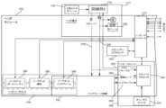
図9は、コンピュータ実装インタラクティブ外科システム200を示す。コンピュータ実装インタラクティブ外科システム200は、多くの点で、コンピュータ実装インタラクティブ外科システム100と類似している。例えば、コンピュータ実装インタラクティブ外科システム200は、多くの点で外科システム102と類似する1つ又は2つ以上の外科システム202を含む。各外科システム202は、リモートサーバ213を含み得るクラウド204と通信する少なくとも1つの外科用ハブ206を含む。一態様では、コンピュータ実装インタラクティブ外科システム200は、例えば、インテリジェント外科用器具、ロボット及び手術室内に位置する他のコンピュータ化装置などの複数の手術室装置に接続されたモジュール式制御タワー236を備える。図10に示すように、モジュール式制御タワー236は、コンピュータシステム210に連結されたモジュール式通信ハブ203を備える。図9の実施例に示すように、モジュール式制御タワー236は、内視鏡239に連結された撮像モジュール238、エネルギー装置241に連結された発生器モジュール240、排煙器モジュール226、吸引/灌注モジュール228、通信モジュール230、プロセッサモジュール232、ストレージアレイ234、任意選択的にディスプレイ237に連結されたスマート装置/器具235及び非接触センサモジュール242に連結されている。手術室装置は、モジュール式制御タワー236を介してクラウドコンピューティングリソース及びデータストレージに連結されている。ロボットハブ222もまた、モジュール式制御タワー236及びクラウドコンピューティングリソースに接続されてもよい。とりわけ、装置/器具235、可視化システム208が、本明細書に記載されるように、有線又は無線通信規格又はプロトコルを介して、モジュール式制御タワー236に連結されてもよい。モジュール式制御タワー236は、撮像モジュール、装置/器具ディスプレイ及び/又は他の可視化システム208から受信した画像を表示及びオーバーレイするためにハブディスプレイ215(例えば、モニタ、スクリーン)に連結されてもよい。ハブディスプレイはまた、モジュール式制御タワーに接続された装置から受信したデータを、画像及びオーバーレイ画像とともに表示してもよい。 FIG. 9 shows a computer-implemented interactive
図10は、モジュール式制御タワー236に連結された複数のモジュールを備える外科用ハブ206を示す。モジュール式制御タワー236は、例えばネットワーク接続装置などのモジュール式通信ハブ203と、例えばローカルでの処理、可視化及び撮像を行うためのコンピュータシステム210と、を備える。図10に示すように、モジュール式通信ハブ203は、モジュール式通信ハブ203に接続できるモジュール(例えば、装置)の数を拡張するために階層化構成で接続されて、モジュールに関連付けられたデータをコンピュータシステム210、クラウドコンピューティングリソース、又はその両方に転送することができる。図10に示すように、モジュール式通信ハブ203内のネットワークハブ/スイッチの各々は、3つの下流ポート及び1つの上流ポートを含む。上流のネットワークハブ/スイッチは、クラウドコンピューティングリソース及びローカルディスプレイ217への通信接続を提供するためにプロセッサに接続されている。クラウド204への通信は、有線通信チャネル又は無線通信チャネルのいずれかを介して行うことができる。 FIG. 10 shows
外科用ハブ206は、非接触センサモジュール242を使用して、手術室の寸法を測定し、また超音波非接触測定装置又はレーザ型非接触測定装置のいずれかを使用して手術室のマップを生成する。その全体が参照により本明細書に組み込まれる「INTERACTIVE SURGICAL PLATFORM」と題する2017年12月28日出願の米国仮特許出願第62/611,341号では、センサモジュールが、手術室のサイズを判定し、かつBluetoothペアリングの距離限界を調整するように構成されているが、同文献中の「Surgical Hub Spatial Awareness Within an Operating Room」の項で説明されるように、超音波ベースの非接触センサモジュールは、超音波のバーストを送信し、超音波のバーストが手術室の外壁に反射したときのエコーを受信することによって手術室を走査する。レーザベースの非接触センサモジュールは、例えば、レーザ光パルスを送信することによって手術室を走査し、手術室の外壁に反射するレーザ光パルスを受信し、送信されたパルスの位相を受信したパルスと比較して手術室のサイズを判定し、Bluetoothペアリング距離限界を調整する。 The
コンピュータシステム210は、プロセッサ244と、ネットワークインターフェース245と、を備える。プロセッサ244は、システムバスを介して、通信モジュール247、ストレージ248、メモリ249、不揮発性メモリ250及び入力/出力インターフェース251に連結されている。システムバスは、任意の様々な利用可能なバスアーキテクチャを使用する、メモリバス若しくはメモリコントローラ、ペリフェラルバス若しくは外部バス、及び/又はローカルバスを含むいくつかのタイプのバス構造(複数可)のうちのいずれかであってもよく、それらのアーキテクチャの例としては、9ビットバス、業界標準アーキテクチャ(ISA)、マイクロチャネルアーキテクチャ(MSA)、拡張ISA(EISA)、インテリジェントドライブエレクトロニクス(IDE)、VESAローカルバス(VLB)、周辺装置相互接続(PCI)、USB、アドバンスドグラフィックスポート(AGP)、パーソナルコンピュータメモリカード国際協会バス(PCMCIA)、小型計算機システムインターフェース(SCSI)又は任意の他の独自バス(proprietary bus)が挙げられるが、これらに限定されない。
プロセッサ244は、Texas Instruments製のARM Cortexの商品名で知られているものなど、任意のシングルコア又はマルチコアプロセッサであってもよい。一態様では、プロセッサは、例えば、Texas Instrumentsから入手可能なLM4F230H5QR ARM Cortex-M4Fプロセッサコアであってもよい。このプロセッサコアは、最大40MHzの256KBのシングルサイクルフラッシュメモリ若しくは他の不揮発性メモリのオンチップメモリ、性能を40MHz超に改善するためのプリフェッチバッファ、32KBのシングルサイクルシリアルランダムアクセスメモリ(SRAM)、StellarisWare(登録商標)ソフトウェアを搭載した内部読み出し専用メモリ(ROM)、2KBの電気的消去可能プログラマブル読み出し専用メモリ(EEPROM)及び/又は、1つ又は2つ以上のパルス幅変調(PWM)モジュール、1つ又は2つ以上の直交エンコーダ入力(QEI)アナログ、12個のアナログ入力チャネルを備える1つ又は2つ以上の12ビットアナログ-デジタル変換器(ADC)を含む。なお、その詳細は、製品データシートで入手可能である。
一態様では、プロセッサ244は、同じくTexas Instruments製のHercules ARM Cortex R4の商品名で知られるTMS570及びRM4xなどの2つのコントローラ系ファミリーを含む安全コントローラを含んでもよい。安全コントローラは、拡張性のある性能、接続性及びメモリの選択肢を提供しながら、高度な集積型安全機構を提供するために、とりわけ、IEC61508及びISO26262の安全限界用途専用に構成されてもよい。 In one aspect, the
システムメモリとしては、揮発性メモリ及び不揮発性メモリが挙げられる。起動中などにコンピュータシステム内の要素間で情報を転送するための基本ルーチンを含む基本入出力システム(BIOS)は、不揮発性メモリに記憶される。例えば、不揮発性メモリとしては、ROM、プログラマブルROM(PROM)、電気的プログラマブルROM(EPROM)、EEPROM又はフラッシュメモリが挙げられ得る。揮発性メモリとしては、外部キャッシュメモリとして機能するランダムアクセスメモリ(RAM)が挙げられる。更に、RAMは、SRAM、ダイナミックRAM(DRAM)、シンクロナスDRAM(SDRAM)、ダブルデータレートSDRAM(DDR SDRAM)、エンハンスドSDRAM(ESDRAM)、シンクリンクDRAM(SLDRAM)及びダイレクトランバスRAM(DRRAM)などの多くの形態で利用可能である。 System memory includes volatile memory and non-volatile memory. The basic input/output system (BIOS), containing the basic routines for transferring information between elements within a computer system, such as during startup, is stored in non-volatile memory. For example, non-volatile memory may include ROM, programmable ROM (PROM), electrically programmable ROM (EPROM), EEPROM, or flash memory. Volatile memory includes random access memory (RAM), which functions as external cache memory. Furthermore, RAM can be classified into SRAM, dynamic RAM (DRAM), synchronous DRAM (SDRAM), double data rate SDRAM (DDR SDRAM), enhanced SDRAM (ESDRAM), sink link DRAM (SLDRAM), and direct run bus RAM (DRRAM). Available in many forms.
コンピュータシステム210はまた、取り外し可能/取り外し不可能な揮発性/不揮発性のコンピュータストレージ媒体、例えばディスクストレージなどを含む。ディスクストレージとしては、磁気ディスクドライブ、フロッピーディスクドライブ、テープドライブ、Jazドライブ、Zipドライブ、LS-60ドライブ、フラッシュメモリカード又はメモリスティックのような装置が挙げられるが、これらに限定されない。加えて、ディスクストレージは、上記のストレージ媒体を、独立して、又は他のストレージ媒体との組み合わせで含むことができる。他のストレージ媒体としては、コンパクトディスクROM装置(CD-ROM)、コンパクトディスク記録可能ドライブ(CD-Rドライブ)、コンパクトディスク書き換え可能ドライブ(CD-RWドライブ)若しくはデジタル多用途ディスクROMドライブ(DVD-ROM)などの光ディスクドライブが挙げられるがこれらに限定されない。ディスクストレージ装置のシステムバスへの接続を容易にするために、取り外し可能な又は取り外し不可能なインターフェースが用いられてもよい。
コンピュータシステム210は、好適な動作環境で説明されるユーザと基本コンピュータリソースとの間で媒介として機能するソフトウェアを含むことを理解されたい。このようなソフトウェアとしてはオペレーティングシステムが挙げられる。ディスクストレージ上に記憶され得るオペレーティングシステムは、コンピュータシステムのリソースを制御及び割り当てするように機能する。システムアプリケーションは、システムメモリ内又はディスクストレージ上のいずれかに記憶されたプログラムモジュール及びプログラムデータを介して、オペレーティングシステムによるリソース管理を活用する。本明細書に記載される様々な構成要素は、様々なオペレーティングシステム又はオペレーティングシステムの組み合わせで実装することができることを理解されたい。 It should be appreciated that
ユーザは、I/Oインターフェース251に連結された入力装置(複数可)を介してコンピュータシステム210にコマンド又は情報を入力する。入力装置としては、マウス、トラックボール、スタイラス、タッチパッドなどのポインティング装置、キーボード、マイクロフォン、ジョイスティック、ゲームパッド、衛星放送受信アンテナ、スキャナ、TVチューナカード、デジタルカメラ、デジタルビデオカメラ、ウェブカメラなどが挙げられるが、これらに限定されない。これら及び他の入力装置は、インターフェースポート(複数可)を介し、システムバスを通じてプロセッサに接続する。インターフェースポート(複数可)としては、例えば、シリアルポート、パラレルポート、ゲームポート及びUSBが挙げられる。出力装置(複数可)は、入力装置(複数可)と同じタイプのポートのうちのいくつかを使用する。したがって、例えば、USBポートを使用して、コンピュータシステムに入力を提供し、コンピュータシステムからの情報を出力装置に出力してもよい。出力アダプタは、特別なアダプタを必要とする出力装置の中でもとりわけ、モニタ、ディスプレイ、スピーカ及びプリンタなどのいくつかの出力装置が存在することを示すために提供される。出力アダプタとしては、出力装置とシステムバスとの間の接続手段を提供するビデオ及びサウンドカードが挙げられるが、これは例示としてのものであり、限定するものではない。リモートコンピュータ(複数可)などの他の装置及び/又は装置のシステムは、入力及び出力機能の両方を提供することに留意されたい。 A user enters commands or information into
コンピュータシステム210は、クラウドコンピュータ(複数可)などの1つ若しくは2つ以上のリモートコンピュータ又はローカルコンピュータへの論理接続を使用するネットワーク化環境で動作することができる。遠隔クラウドコンピュータ(複数可)は、パーソナルコンピュータ、サーバ、ルータ、ネットワークPC、ワークステーション、マイクロプロセッサベースの機器、ピア装置又は他の一般的なネットワークノードなどであり得るが、典型的には、コンピュータシステムに関して説明される要素の多く又は全てを含む。簡潔にするために、リモートコンピュータ(複数可)とともに、メモリストレージ装置のみが示される。リモートコンピュータ(複数可)は、ネットワークインターフェースを介してコンピュータシステムに論理的に接続され、続いて、通信接続部を介して物理的に接続される。ネットワークインターフェースは、ローカルエリアネットワーク(LAN)及びワイドエリアネットワーク(WAN)などの通信ネットワークを包含する。LAN技術としては、光ファイバ分散データインターフェース(FDDI)、銅線分散データインターフェース(CDDI)、Ethernet/IEEE802.3、Token Ring/IEEE802.5などが挙げられる。WAN技術としては、ポイントツーポイントリンク、統合サービスデジタルネットワーク(ISDN)及びその変形などの回路交換ネットワーク、パケット交換ネットワーク並びにデジタル加入者回線(DSL)が挙げられるが、これらに限定されない。
様々な態様では、図10のコンピュータシステム210、図9~図10の撮像モジュール238及び/又は可視化システム208及び/又はプロセッサモジュール232は、画像プロセッサ、画像処理エンジン、メディアプロセッサ又はデジタル画像の処理に使用される任意の専門的なデジタル信号プロセッサ(digital signal processor、DSP)を含んでもよい。画像プロセッサは、単一命令複数データ(SIMD)、又は複数命令複数データ(MIMD)技術を用いた並列コンピューティングを用いて速度及び効率を高めることができる。デジタル画像処理エンジンは、様々なタスクを実施することができる。画像プロセッサは、マルチコアプロセッサアーキテクチャを備えるチップ上のシステムであってもよい。 In various aspects, the
通信接続部(複数可)とは、ネットワークインターフェースをバスに接続するために用いられるハードウェア/ソフトウェアを指す。例示の明瞭さのため通信接続部はコンピュータシステム内部に示されているが、通信接続部はコンピュータシステム210の外部にあってもよい。例示のみを目的として、ネットワークインターフェースへの接続に必要なハードウェア/ソフトウェアとしては、通常の電話グレードモデム、ケーブルモデム及びDSLモデムを含むモデム、ISDNアダプタ並びにイーサネットカードなどの内部及び外部技術が挙げられる。 Communication connection(s) refers to the hardware/software used to connect the network interface to the bus. Although the communication connections are shown internal to the computer system for clarity of illustration, the communication connections may be external to the
図11は、本開示の少なくとも1つの態様による、USBネットワークハブ300装置の一態様の機能ブロック図を示す。示される態様では、USBネットワークハブ装置300は、Texas Instruments製のTUSB2036集積回路ハブを用いる。USBネットワークハブ300は、USB2.0規格に準拠する、上流USB送受信機ポート302と、最大3つの下流USB送受信機ポート304、306、308と、を提供するCMOS装置である。上流USB送受信機ポート302は、差動データプラス(DP0)入力とペアリングされた差動データマイナス(DM0)入力を含む差動ルートデータポートである。3つの下流USB送受信機ポート304、306、308は、各ポートが差動データマイナス(DM1~DM3)出力とペアリングした差動データプラス(DP1~DP3)出力を含む差動データポートである。 FIG. 11 illustrates a functional block diagram of one aspect of a
USBネットワークハブ300装置は、マイクロコントローラの代わりにデジタル状態マシンを備えて実装され、ファームウェアのプログラミングを必要としない。完全準拠したUSB送受信機が、上流USB送受信機ポート302及び全ての下流USB送受信機ポート304、306、308の回路に組み込まれている。下流USB送受信機ポート304、306、308は、ポートに取り付けられた装置の速度に応じて立ち上がり速度を自動的に設定することによって、最高速度及び低速の装置の両方を支持する。USBネットワークハブ300装置は、バスパワーモード又はセルフパワーモードのいずれかで構成されてもよく、電力を管理するためのハブパワー論理312を含む。 The
USBネットワークハブ300装置は、シリアルインターフェースエンジン310(SIE)を含む。SIE310は、USBネットワークハブ300ハードウェアのフロントエンドであり、USB仕様書の第8章に記載されているプロトコルの大部分を取り扱う。SIE310は、典型的には、トランザクションレベルまでのシグナリングを理解する。これが取り扱う機能としては、パケット認識、トランザクションの並べ替え、SOP、EOP、RESET及びRESUME信号の検出/生成、クロック/データ分離、非ゼロ復帰逆転(NRZI)データ符号化/復号及びビットスタッフィング、CRC生成及びチェック(トークン及びデータ)、パケットID(PID)の生成及びチェック/復号、並びに/又はシリアル-パラレル/パラレル-シリアル変換が挙げられ得る。310は、クロック入力314を受信し、ポート論理回路320、322、324を介して上流USB送受信機ポート302と下流USB送受信機ポート304、306、308との間の通信を制御するため、サスペンド/レジューム論理並びにフレームタイマ316回路及びハブリピータ回路318に連結されている。SIE310は、シリアルEEPROMインターフェース330を介してシリアルEEPROMからコマンドを制御するように、インターフェース論理を介してコマンドデコーダ326に連結される。 The
様々な態様では、USBネットワークハブ300は、最大6つの論理層(階層)内に構成された127個の機能を単一のコンピュータに接続することができる。更に、USBネットワークハブ300は、通信及び電力分配の両方を提供する標準化された4本のワイヤケーブルを使用して全ての周辺機器に接続することができる。電力構成は、バスパワーモード及びセルフパワーモードである。USBネットワークハブ300は、個々のポート電力管理又は連動ポート電力管理のいずれかを備えるバスパワーハブ及び個々のポート電力管理又は連動ポート電力管理のいずれかを備えるセルフパワーハブの、電力管理の4つのモードを支持するように構成されてもよい。一態様では、USBケーブル、USBネットワークハブ300を使用して、上流USB送受信機ポート302はUSBホストコントローラにプラグ接続され、下流USB送受信機ポート304、306、308はUSBに互換性のある装置を接続するために露出される、といった具合である。 In various aspects,
外科用器具のハードウェア
図12は、本開示の1つ又は2つ以上の態様による、外科用器具又はツールの制御システム470の論理図を示す。システム470は、制御回路を備える。制御回路は、プロセッサ462及びメモリ468を備えるマイクロコントローラ461を含む。例えば、センサ472、474、476のうちの1つ又は2つ以上が、プロセッサ462にリアルタイムなフィードバックを提供する。モータ駆動器492によって駆動されるモータ482は、長手方向に移動可能な変位部材を動作可能に連結して、クランプアーム閉鎖部材を駆動する。追跡システム480は、長手方向に移動可能な変位部材の位置を判定するように構成されている。位置情報は、長手方向に移動可能な駆動部材の位置及び閉鎖部材の位置を判定するようにプログラム又は構成可能なプロセッサ462に提供される。閉鎖管の移動、シャフトの回転、関節運動、若しくはクランプアームの閉鎖、又は上記の組み合わせを制御するために、ツールドライバインターフェースに追加のモータが提供されてもよい。ディスプレイ473は、器具の様々な動作条件を表示し、データ入力のためのタッチスクリーン機能を含んでもよい。ディスプレイ473上に表示された情報は、内視鏡撮像モジュールを介して取得された画像とオーバーレイさせることができる。 Surgical Instrument Hardware FIG. 12 depicts a logic diagram of a surgical instrument or
一態様では、マイクロコントローラ461は、Texas Instruments製のARM Cortexの商品名で知られているものなど、任意のシングルコア又はマルチコアプロセッサであってもよい。一態様では、主マイクロコントローラ461は、例えば、その詳細が製品データシートで入手可能である、最大40MHzの256KBのシングルサイクルフラッシュメモリ若しくは他の不揮発性メモリのオンチップメモリ、性能を40MHz超に改善するためのプリフェッチバッファ、32KBのシングルサイクルSRAM、StellarisWare(登録商標)ソフトウェアを搭載した内部ROM、2KBのEEPROM、1つ若しくは2つ以上のPWMモジュール、1つ若しくは2つ以上のQEIアナログ、及び/又は12個のアナログ入力チャネルを備える1つ若しくは2つ以上の12ビットADCを含む、Texas Instrumentsから入手可能なLM4F230H5QR ARM Cortex-M4Fプロセッサコアであってもよい。 In one aspect,
一態様では、マイクロコントローラ461は、同じくTexas Instruments製のHercules ARM Cortex R4の商品名で知られるTMS570及びRM4xなどの2つのコントローラ系ファミリーを含む安全コントローラを含んでもよい。安全コントローラは、拡張性のある性能、接続性及びメモリの選択肢を提供しながら、高度な集積型安全機構を提供するために、とりわけ、IEC61508及びISO26262の安全限界用途専用に構成されてもよい。 In one aspect, the
マイクロコントローラ461は、ナイフ、関節運動システム、クランプアーム、又は上記の組み合わせの速度及び位置の正確な制御などの様々な機能を実施するようにプログラムされてもよい。一態様では、マイクロコントローラ461は、プロセッサ462及びメモリ468を含む。電気モータ482は、ギアボックス、及び関節運動又はナイフシステムへの機械的連結部を備えたブラシ付き直流(DC)モータであってもよい。一態様では、モータドライバ492は、Allegro Microsystems,Incから入手可能なA3941であってもよい。他のモータドライバを、絶対位置付けシステムを備える追跡システム480で使用するために容易に代用することができる。絶対位置付けシステムの詳細な説明は、その全体が参照により本明細書に組み込まれる「SYSTEMS AND METHODS FOR CONTROLLING A SURGICAL STAPLING AND CUTTING INSTRUMENT」と題する2017年10月19日公開の米国特許出願公開第2017/0296213号に記載されている。
マイクロコントローラ461は、変位部材及び関節運動システムの速度及び位置に対する正確な制御を提供するようにプログラムされてもよい。マイクロコントローラ461は、マイクロコントローラ461のソフトウェア内で応答を計算するように構成されてもよい。計算された応答は、実際のシステムの測定された応答と比較されて「観測された」応答が得られ、これが実際のフィードバックの判定に使用される。観測された応答は、シミュレートされた応答の滑らかで連続的な性質と、測定された応答とのバランスをとる好適な調整された値であり、これはシステムに及ぼす外部の影響を検出することができる。
一態様では、モータ482は、モータドライバ492によって制御されてもよく、外科用器具又はツールの発射システムによって用いられ得る。様々な形態において、モータ482は、例えば、約25,000RPMの最大回転速度を有するブラシ付きDC駆動モータであってもよい。他の構成では、モータ482としては、ブラシレスモータ、コードレスモータ、同期モータ、ステッパモータ、又は任意の他の好適な電気モータが挙げられ得る。モータ駆動体492は、例えば、電界効果トランジスタ(FET)を含むHブリッジドライバを備えてもよい。モータ482は、外科用器具又はツールに制御電力を供給するために、ハンドル組立体又はツールハウジングに解除可能に装着された電源組立体によって給電され得る。電源組立体は、外科用器具又はツールに給電するための電源として使用され得る、直列に接続された多数の電池セルを含み得る電池を備えてもよい。特定の状況下では、電源組立体の電池セルは、交換可能及び/又は再充電可能な電池セルであってよい。少なくとも1つの例では、電池セルは、電源組立体に連結可能かつ電源組立体から分離可能であり得るリチウムイオン電池であり得る。 In one aspect,
モータドライバ492は、Allegro Microsystems,Incから入手可能なA3941であってもよい。A3941 492は、特にブラシ付きDCモータなどの誘導負荷を目的として設計された外部Nチャネルパワー金属酸化膜半導体電界効果トランジスタ(MOSFET)とともに使用するためのフルブリッジコントローラである。ドライバ492は、固有の電荷ポンプレギュレータを備え、これは、完全(>10V)ゲート駆動を7Vまでの電池電圧に提供し、A3941が5.5Vまでの低減ゲート駆動で動作することを可能にする。NチャネルMOSFETに必要な上記の電池供給電圧を与えるために、ブートストラップコンデンサが用いられてもよい。ハイサイド駆動用の内部電荷ポンプにより、DC(100%デューティサイクル)動作が可能となる。フルブリッジは、ダイオード又は同期整流を使用して高速又は低速減衰モードで駆動され得る。低速減衰モードでは、電流の再循環は、ハイサイドのFETによっても、ローサイドのFETによっても可能である。電力FETは、抵抗器で調節可能なデッドタイムによって、シュートスルーから保護される。統合診断は、低電圧、温度過昇、及びパワーブリッジの異常を指示するものであり、ほとんどの短絡状態下でパワーMOSFETを保護するように構成され得る。他のモータドライバを、絶対位置付けシステムを備えた追跡システム480で使用するために容易に代用することができる。
追跡システム480は、本開示の一態様による位置センサ472を備える制御されたモータ駆動回路配置を備える。絶対位置付けシステム用の位置センサ472は、変位部材の位置に対応する固有の位置信号を提供する。一態様では、変位部材は、ギア減速機組立体の対応する駆動ギアと噛合係合するための駆動歯のラックを備える長手方向に移動可能な駆動部材を表す。他の態様では、変位部材は、駆動歯のラックを含むように適合され、構成され得る発射部材を表す。更に別の態様では、変位部材は、クランプアームを開閉するための長手方向変位部材を表し、これは駆動歯のラックを含むように適合及び構成され得る。他の態様では、変位部材は、ステープラ、超音波、若しくは電気外科用装置のクランプアーム、又は上記の組み合わせを開閉するように構成されたクランプアーム閉鎖部材を表す。したがって、本明細書で使用されるとき、変位部材という用語は、一般的に、駆動部材、クランプアーム、又は変位され得る任意の要素など、外科用器具又はツールの任意の可動部材を指すために使用される。したがって、絶対位置付けシステムは、実際には、長手方向に移動可能な駆動部材の直線変位を追跡することによって、クランプアームの変位を追跡することができる。他の態様では、絶対位置付けシステムは、開閉プロセスにおけるクランプアームの位置を追跡するように構成され得る。様々な他の態様では、変位部材は、直線変位を測定するのに好適な任意の位置センサ472に連結されてもよい。したがって、長手方向に移動可能な駆動部材、若しくはクランプアーム、又はこれらの組み合わせは、任意の好適な直線変位センサに連結されてもよい。直線変位センサは、接触式変位センサ又は非接触式変位センサを含んでもよい。直線変位センサは、線形可変差動変圧器(LVDT)、差動可変磁気抵抗型変換器(DVRT)、スライドポテンショメータ、移動可能な磁石及び一連の直線状に配置されたホール効果センサを備える磁気感知システム、固定された磁石及び一連の移動可能な直線状に配置されたホール効果センサを備える磁気感知システム、移動可能な光源及び一連の直線状に配置された光ダイオード若しくは光検出器を備える光学検出システム、固定された光源及び一連の移動可能な直線状に配置された光ダイオード若しくは光検出器を備える光学検出システム、又はこれらの任意の組み合わせを含んでもよい。
電気モータ482は、変位部材上の駆動歯の組又はラックと噛合係合で装着されるギア組立体と動作可能にインターフェースする回転式シャフトを含んでもよい。センサ素子は、位置センサ472素子の1回転が、変位部材のいくつかの直線長手方向並進に対応するように、ギア組立体に動作可能に連結されてもよい。ギアリング及びセンサの構成は、ラックピニオン構成によって直線アクチュエータに、又はスパーギア若しくは他の接続によって回転アクチュエータに接続することができる。電源は、絶対位置付けシステムに電力を供給し、出力インジケータは、絶対位置付けシステムの出力を表示することができる。変位部材は、ギア減速機組立体の対応する駆動ギアと噛合係合するための、その上に形成された駆動歯のラックを備える長手方向に移動可能な駆動部材を表す。変位部材は、クランプアームを開閉する長手方向に移動可能な発射部材を表す。
位置センサ472に関連付けられるセンサ素子の1回転は、変位部材の長手方向直線変位d1に相当し、d1は、変位部材に連結したセンサ素子の1回転した後で、変位部材が点「a」から点「b」まで移動する長手方向の直線距離である。センサ機構は、位置センサ472が変位部材のフルストロークに対して1回以上の回転を完了する結果をもたらすギアの減速を介して連結されてもよい。位置センサ472は、変位部材のフルストロークに対して複数回の回転を完了することができる。 One rotation of the sensor element associated with the
位置センサ472の2回以上の回転に対する固有の位置信号を提供するために、一連のスイッチ(ここでnは1よりも大きい整数である)が、単独で、又はギアの減速との組み合わせで用いられてもよい。スイッチの状態はマイクロコントローラ461にフィードバックされ、マイクロコントローラ461は論理を適用して、変位部材の長手方向の直線変位d1+d2+...dnに対応する固有の位置信号を判定する。位置センサ472の出力はマイクロコントローラ461に提供される。センサ機構の位置センサ472は、位置信号又は値の固有の組み合わせを出力する、磁気センサ、電位差計などのアナログ回転センサ、又はアナログホール効果素子のアレイを備えてもよい。 A series of switches (where n is an integer greater than 1) may be used alone or in combination with a gear reduction to provide unique position signals for more than one revolution of the
位置センサ472は、例えば、全磁界又は磁界のベクトル成分を測定するかどうかに基づいて分類される磁気センサなどの、任意の数の磁気感知素子を備えてもよい。両タイプの磁気センサを生産するために使用される技術は、物理学及び電子工学の多数の側面を含んでいる。磁界の感知に使用される技術としては、とりわけ、探りコイル、フラックスゲート、光ポンピング、核摂動(nuclear precession)、SQUID、ホール効果、異方性磁気抵抗、巨大磁気抵抗、磁気トンネル接合、巨大磁気インピーダンス、磁歪/圧電複合材、磁気ダイオード、磁気トランジスタ、光ファイバ、磁気光学、及び微小電気機械システムベースの磁気センサが挙げられる。
一態様では、絶対位置付けシステムを備える追跡システム480の位置センサ472は、磁気回転絶対位置付けシステムを備える。位置センサ472は、Austria Microsystems,AGから入手可能なAS5055EQFTシングルチップ磁気回転位置センサとして実装されてもよい。位置センサ472は、マイクロコントローラ461とインターフェースされて絶対位置付けシステムを提供する。位置センサ472は、低電圧低電力の構成要素であり、磁石の上方に位置する位置センサ472のエリアに、4つのホール効果素子を含む。また、高解像度ADC及びスマート電力管理コントローラがチップ上に設けられている。加算、減算、ビットシフト、及びテーブル参照演算のみを必要とする、双曲線関数及び三角関数を計算する簡潔かつ効率的なアルゴリズムを実装するために、桁毎法及びボルダーアルゴリズムとしても知られる、座標回転デジタルコンピュータ(CORDIC)プロセッサが設けられる。角度位置、アラームビット、及び磁界情報は、シリアル周辺インターフェース(SPI)インターフェースなどの標準的なシリアル通信インターフェースを介してマイクロコントローラ461に伝送される。位置センサ472は、12ビット又は14ビットの解像度を提供する。位置センサ472は、小型のQFN16ピン4×4×0.85mmパッケージで提供されるAS5055チップであってもよい。 In one aspect,
絶対位置付けシステムを備える追跡システム480は、PID、状態フィードバック、及び適応コントローラなどのフィードバックコントローラを備えてもよく、かつ/又はこれを実装するようにプログラムされてもよい。電源は、フィードバックコントローラからの信号を、システムへの物理的入力、この場合は電圧へと変換する。他の例としては、電圧、電流、及び力のPWMが挙げられる。位置センサ472によって測定される位置に加えて、物理的システムの物理パラメータを測定するために、他のセンサ(複数可)が設けられてもよい。いくつかの態様では、他のセンサ(複数可)としては、その全体が参照により本明細書に組み込まれる、「STAPLE CARTRIDGE TISSUE THICKNESS SENSOR SYSTEM」と題する2016年5月24日発行の米国特許第9,345,481号、その全体が参照により本明細書に組み込まれる、「STAPLE CARTRIDGE TISSUE THICKNESS SENSOR SYSTEM」と題する2014年9月18日公開の米国特許出願公開第2014/0263552号、及びその全体が参照により本明細書に組み込まれる、「TECHNIQUES FOR ADAPTIVE CONTROL OF MOTOR VELOCITY OF A SURGICAL STAPLING AND CUTTING INSTRUMENT」と題する2017年6月20日出願の米国特許出願第15/628,175号に記載されているものなどのセンサ配置を挙げることができる。デジタル信号処理システムでは、絶対位置付けシステムはデジタルデータ取得システムに連結され、ここで絶対位置付けシステムの出力は有限の解像度及びサンプリング周波数を有する。絶対位置付けシステムは、計算された応答を測定された応答に向けて駆動する加重平均及び理論制御ループなどのアルゴリズムを使用して、計算された応答を測定された応答と組み合わせるために、比較及び組み合わせ回路を備え得る。入力を知ることによって物理的システムの状態及び出力がどうなるかを予測するために、物理的システムの計算された応答は、質量、慣性、粘性摩擦、誘導抵抗などの特性を考慮に入れる。
絶対位置付けシステムは、単にモータ482がとった前方又は後方へのステップの数を計数して装置アクチュエータ、駆動バー、ナイフなどの位置を推定する従来の回転エンコーダで必要となり得るような、変位部材をリセット(ゼロ又はホーム)位置へ後退又は前進させることなしに、器具の電源投入時に変位部材の絶対位置を提供する。 Absolute positioning systems employ a displacement member, such as may be required with conventional rotary encoders that simply count the number of forward or backward steps taken by
例えば歪みゲージ又は微小歪みゲージなどのセンサ474は、例えば、アンビルに適用される閉鎖力を示すことができる、クランプ動作中にアンビルに及ぼされる歪みの振幅などのエンドエフェクタの1つ又は2つ以上のパラメータを測定するように構成される。測定された歪みは、デジタル信号に変換されて、プロセッサ462に提供される。センサ474の代わりに、又はこれに加えて、例えば、負荷センサなどのセンサ476が、閉鎖駆動システムが超音波又は電気外科用器具内のステープラ又はクランプアーム内のアンビルに加える閉鎖力を測定することができる。例えば、負荷センサなどのセンサ476は、外科用器具若しくはツールのクランプアームに連結された閉鎖部材に加えられる発射力、又はクランプアームによって超音波若しくは電気外科用器具のジョー内に位置する組織に加えられる力を測定することができる。代替的に、モータ482により引き込まれる電流を測定するために、電流センサ478を用いることができる。変位部材はまた、クランプアームに係合してクランプアームを開閉するように構成されてもよい。力センサは、組織上のクランプ力を測定するように構成されてもよい。変位部材を前進させるのに必要な力は、例えば、モータ482によって引き込まれる電流に相当し得る。測定された力は、デジタル信号に変換されて、プロセッサ462に提供される。 A
一形態では、歪みゲージセンサ474を使用して、エンドエフェクタによって組織に加えられる力を測定することができる。治療されている組織に対するエンドエフェクタによる力を測定するために、歪みゲージをエンドエフェクタに連結することができる。エンドエフェクタによって把持された組織に加えられる力を測定するためのシステムは、例えば、エンドエフェクタの1つ又は2つ以上のパラメータを測定するように構成された微小歪みゲージなどの歪みゲージセンサ474を備える。一態様では、歪みゲージセンサ474は、組織圧縮を示し得る、クランプ動作中にエンドエフェクタのジョー部材に及ぼされる歪みの振幅又は規模を測定することができる。測定された歪みは、デジタル信号に変換されて、マイクロコントローラ461のプロセッサ462に提供される。負荷センサ476は、例えば、アンビルとステープルカートリッジとの間に捕捉された組織を切断するために、ナイフ要素を動作させるために使用される力を測定することができる。負荷センサ476は、例えば、クランプアームと超音波ブレードとの間に組織を捕捉するために、又はクランプアームと電気外科用器具のジョーとの間に組織を捕捉するために、クランプアーム要素を操作するのに使用される力を測定することができる。磁界センサは、捕捉された組織の厚さを測定するために用いることができる。磁界センサの測定値もデジタル信号に変換されて、プロセッサ462に提供され得る。 In one form,
センサ474、476によってそれぞれ測定される、組織圧縮、組織の厚さ、及び/又はエンドエフェクタを組織上で閉鎖するのに必要な力の測定値は、発射部材の選択された位置、及び/又は発射部材の速度の対応する値を特性決定するために、マイクロコントローラ461によって使用することができる。一例では、メモリ468は、評価の際にマイクロコントローラ461によって用いることができる技術、等式及び/又はルックアップテーブルを記憶することができる。 Measurements of tissue compression, tissue thickness, and/or the force required to close the end effector on the tissue, as measured by
外科用器具又はツールの制御システム470はまた、図8~図11に示されるようにモジュール式通信ハブと通信するための有線通信回路又は無線通信回路を備えてもよい。 The surgical instrument or
図13は、本開示の一態様による、外科用器具又はツールの態様を制御するように構成された制御回路500を示す。制御回路500は、本明細書に説明される様々なプロセスを実装するように構成することができる。制御回路500は、少なくとも1つのメモリ回路504に連結された1つ又は2つ以上のプロセッサ502(例えば、マイクロプロセッサ、マイクロコントローラ)を備えるマイクロコントローラを備えることができる。メモリ回路504は、プロセッサ502によって実行されると、本明細書に記載される様々なプロセスを実装するための機械命令をプロセッサ502に実行させる、機械実行可能命令を記憶する。プロセッサ502は、当該技術分野で既知の多数のシングルコア又はマルチコアプロセッサのうちの任意の1つであってもよい。メモリ回路504は、揮発性及び不揮発性の記憶媒体を備えることができる。プロセッサ502は、命令処理ユニット506及び演算ユニット508を含んでもよい。命令処理ユニットは、本開示のメモリ回路504から命令を受信するように構成されてもよい。 FIG. 13 illustrates a
図14は、本開示の一態様による、外科用器具又はツールの態様を制御するように構成された組み合わせ論理回路510を示す。組み合わせ論理回路510は、本明細書に説明される様々なプロセスを実装するように構成することができる。組み合わせ論理回路510は、入力514で外科用器具又はツールと関連付けられたデータを受信し、組み合わせ論理512によってデータを処理し、出力516を提供するように構成された組み合わせ論理512を備える有限状態マシンを備えてもよい。 FIG. 14 illustrates
図15は、本開示の一態様による、外科用器具又はツールの態様を制御するように構成された順序論理回路520を示す。順序論理回路520又は組み合わせ論理522は、本明細書に記載される様々なプロセスを実装するように構成することができる。順序論理回路520は有限状態マシンを含んでもよい。順序論理回路520は、例えば、組み合わせ論理522、少なくとも1つのメモリ回路524、及びクロック529を含んでもよい。少なくとも1つのメモリ回路524は、有限状態マシンの現在の状態を記憶することができる。特定の例では、順序論理回路520は、同期式又は非同期式であってもよい。組み合わせ論理522は、入力526から外科用器具又はツールと関連付けられたデータを受信し、組み合わせ論理522によってデータを処理し、出力528を提供するように構成される。他の態様では、回路は、プロセッサ(例えば、図13のプロセッサ502)と、本明細書の様々なプロセスを実装する有限状態マシンと、の組み合わせを含んでもよい。他の態様では、有限状態マシンは、組み合わせ論理回路(例えば図14の組み合わせ論理回路510)と順序論理回路520との組み合わせを含むことができる。 FIG. 15 illustrates a
図16は、様々な機能を実施するために起動され得る複数のモータを備える外科用器具又はツールを示す。特定の例では、第1のモータを起動させて第1の機能を実施することができ、第2のモータを起動させて第2の機能を実施することができ、第3のモータを起動させて第3の機能を実施することができ、第4のモータを起動させて第4の機能を実施することができる、といった具合である。特定の例では、ロボット外科用器具600の複数のモータは個々に起動されて、エンドエフェクタにおいて発射運動、閉鎖運動、及び/又は関節運動を生じさせることができる。発射運動、閉鎖運動、及び/又は関節運動は、例えばシャフト組立体を介してエンドエフェクタに伝達することができる。 FIG. 16 shows a surgical instrument or tool with multiple motors that can be activated to perform various functions. In particular examples, a first motor can be activated to perform a first function, a second motor can be activated to perform a second function, and a third motor can be activated to perform a second function. A fourth motor can be activated to perform a third function, a fourth motor can be activated to perform a fourth function, and so on. In certain examples, multiple motors of robotic
特定の例では、外科用器具システム又はツールは発射モータ602を含んでもよい。発射モータ602は、具体的にはクランプアーム閉鎖部材を変位させるために、モータ602によって生成された発射運動をエンドエフェクタに伝達するように構成することができる、発射モータ駆動組立体604に動作可能に連結されてもよい。閉鎖部材は、モータ602の方向を逆転させることによって後退させられて、それによって更にクランプアームを開放させてもよい。 In certain examples, a surgical instrument system or tool may include a firing
特定の例では、外科用器具又はツールは閉鎖モータ603を含んでもよい。閉鎖モータ603は、具体的には閉鎖管を変位させてアンビルを閉鎖し、アンビルとステープルカートリッジとの間で組織を圧縮するためにモータ603によって生成された閉鎖運動をエンドエフェクタに伝達するように構成され得る、閉鎖モータ駆動組立体605と動作可能に連結されてもよい。閉鎖モータ603は、具体的には閉鎖管を変位させてクランプアームを閉鎖し、クランプアームと、電気外科用装置の超音波ブレード又はジョー部材のいずれかと、の間で組織を圧縮するためにモータ603によって生成された閉鎖運動をエンドエフェクタに伝達するように構成され得る、閉鎖モータ駆動組立体605と動作可能に連結されてもよい。閉鎖運動によって、例えば、エンドエフェクタが開放構成から近似構成へと移行して組織を捕捉することができる。エンドエフェクタは、モータ603の方向を逆転させることによって開放位置に移行され得る。 In certain examples, the surgical instrument or tool may include a
特定の例では、外科用器具又はツールは、例えば、1つ又は2つ以上の関節運動モータ606a、606bを含んでもよい。モータ606a、606bは、モータ606a、606bによって生成された関節運動をエンドエフェクタに伝達するように構成され得る、対応する関節運動モータ駆動組立体608a、608bに動作可能に連結され得る。特定の例では、関節運動によって、例えば、エンドエフェクタがシャフトに対して関節運動することができる。 In certain examples, a surgical instrument or tool may include one or
上述したように、外科用器具又はツールは、様々な独立した機能を実施するように構成され得る複数のモータを含んでもよい。特定の例では、外科用器具又はツールの複数のモータは、他のモータが停止した状態を維持している間に、個別に又は別個に起動させて、1つ又は2つ以上の機能を実施することができる。例えば、関節運動モータ606a、606bを起動させて、発射モータ602が停止した状態を維持している間に、エンドエフェクタを関節運動させることができる。代替的に、発射モータ602を起動させて、関節運動モータ606が停止した状態を維持している間に、複数のステープルを発射させ、及び/又は切刃を前進させることができる。更に、閉鎖モータ603は、本明細書の以下でより詳細に説明されるとおり、閉鎖管又は閉鎖部材を遠位に前進させるために、発射モータ602と同時に起動させてもよい。 As mentioned above, a surgical instrument or tool may include multiple motors that may be configured to perform a variety of independent functions. In certain instances, multiple motors of a surgical instrument or tool may be activated individually or separately to perform one or more functions while other motors remain stopped. can do. For example,
特定の例では、外科用器具又はツールは、外科用器具又はツールの複数のモータとともに用いることができる、共通の制御モジュール610を含んでもよい。特定の例では、共通の制御モジュール610は、一度に複数のモータのうちの1つに対応することができる。例えば、共通の制御モジュール610は、ロボット外科用器具の複数のモータに対して個々に連結可能かつ分離可能であってもよい。特定の例では、外科用器具又はツールの複数のモータは、共通の制御モジュール610などの1つ又は2つ以上の共通の制御モジュールを共有してもよい。特定の例では、外科用器具又はツールの複数のモータは、共通の制御モジュール610に独立してかつ選択的に係合することができる。特定の例では、共通の制御モジュール610は、外科用器具又はツールの複数のモータのうちの一方とのインターフェース接続から、外科用器具又はツールの複数のモータのうちのもう一方とのインターフェース接続へと選択的に切り替えることができる。 In certain examples, a surgical instrument or tool may include a
少なくとも1つの例では、共通の制御モジュール610は、関節運動モータ606a、606bとの動作可能な係合と、発射モータ602又は閉鎖モータ603のいずれかとの動作可能な係合と、の間で選択的に切り替えることができる。少なくとも1つの実施例では、図16に示すように、スイッチ614は、複数の位置及び/又は状態間を移動又は移行させることができる。例えば、第1の位置616では、スイッチ614は、共通の制御モジュール610を発射モータ602と電気的に連結してもよく、第2の位置617では、スイッチ614は、共通の制御モジュール610を閉鎖モータ603と電気的に連結してもよく、第3の位置618aでは、例えば、スイッチ614は、共通の制御モジュール610を第1の関節運動モータ606aと電気的に連結してもよく、第4の位置618bでは、スイッチ614は、共通の制御モジュール610を第2の関節運動モータ606bと電気的に連結してもよい。特定の例では、同時に、別個の共通の制御モジュール610を、発射モータ602、閉鎖モータ603、及び関節運動モータ606a、606bと電気的に連結してもよい。特定の例では、スイッチ614は、機械的スイッチ、電気機械的スイッチ、固体スイッチ、又は任意の好適な切り替え機構であってもよい。 In at least one example,
モータ602、603、606a、606bの各々は、モータのシャフト上の出力トルクを測定するためのトルクセンサを備えてもよい。エンドエフェクタ上の力は、ジョーの外側の力センサによって、又はジョーを作動させるモータのトルクセンサなどによって、任意の従来の様式で感知されてもよい。 Each of the
様々な例では、図16に示されるように、共通の制御モジュール610は、1つ又は2つ以上のHブリッジFETを備え得るモータドライバ626を備えてもよい。モータドライバ626は、例えば、マイクロコントローラ620(「コントローラ」)からの入力に基づいて、電源628から共通の制御モジュール610に連結されたモータへと伝達された電力を変調してもよい。特定の例では、上述したように、例えば、モータが共通の制御モジュール610に連結されている間にマイクロコントローラ620を用いて、モータによって引き込まれる電流を判定することができる。 In various examples, as shown in FIG. 16, the
特定の例では、マイクロコントローラ620は、マイクロプロセッサ622(「プロセッサ」)と、1つ若しくは2つ以上の非一時的コンピュータ可読媒体又はメモリユニット624(「メモリ」)と、を含んでもよい。特定の例では、メモリ624は、様々なプログラム命令を記憶することができ、それが実行されると、プロセッサ622に、本明細書に記載される複数の機能及び/又は計算を実施させることができる。特定の例では、メモリユニット624のうちの1つ又は2つ以上が、例えば、プロセッサ622に連結されてもよい。様々な態様では、マイクロコントローラ620は、有線若しくは無線チャネル、又はこれらの組み合わせを介して通信してもよい。 In certain examples,
特定の例では、電源628を用いて、例えばマイクロコントローラ620に電力を供給してもよい。特定の例では、電源628は、例えばリチウムイオン電池などの電池(又は「電池パック」若しくは「電源パック」)を含んでもよい。特定の例では、電池パックは、外科用器具600に電力を供給するため、ハンドルに解除可能に装着されるように構成されてもよい。直列で接続された多数の電池セルを、電源628として使用してもよい。特定の例では、電源628は、例えば、交換可能及び/又は再充電可能であってもよい。 In certain examples,
様々な例では、プロセッサ622は、モータドライバ626を制御して、共通の制御モジュール610に連結されたモータの位置、回転方向、及び/又は速度を制御することができる。特定の例では、プロセッサ622は、モータドライバ626に信号伝達して、共通の制御モジュール610に連結されるモータを停止及び/又は無効化することができる。「プロセッサ」という用語は、本明細書で使用されるとき、任意の好適なマイクロプロセッサ、マイクロコントローラ、又は、コンピュータの中央処理装置(central processing unit、CPU)の機能を1つの集積回路又は最大で数個の集積回路上で統合した他の基本コンピューティング装置を含むと理解されるべきである。プロセッサ622は、デジタルデータを入力として受理し、メモリに記憶された命令に従ってそのデータを処理し、結果を出力として提供する、多目的のプログラム可能装置である。これは、内部メモリを有するので、逐次的デジタル論理の一例である。プロセッサは、二進数法で表される数字及び記号で動作する。 In various examples,
一例では、プロセッサ622は、Texas Instruments製のARM Cortexの商品名で知られているものなど、任意のシングルコア又はマルチコアプロセッサであってもよい。特定の例では、マイクロコントローラ620は、例えばTexas Instrumentsから入手可能なLM 4F230H5QRであってもよい。少なくとも1つの実施例では、Texas InstrumentsのLM4F230H5QRは、製品データシートで容易に利用可能な機能の中でもとりわけ、最大40MHzの256KBのシングルサイクルフラッシュメモリ若しくは他の不揮発性メモリのオンチップメモリ、性能を40MHz超に改善するためのプリフェッチバッファ、32KBのシングルサイクルSRAM、StellarisWare(登録商標)ソフトウェアを搭載した内部ROM、2KBのEEPROM、1つ又は2つ以上のPWMモジュール、1つ又は2つ以上のQEIアナログ、12個のアナログ入力チャネルを備える1つ又は2つ以上の12ビットADCを含むARM Cortex-M4Fプロセッサコアである。他のマイクロコントローラが、モジュール4410と共ともに使用するのに容易に代用されてもよい。したがって、本開示は、この文脈に限定されるべきではない。 In one example,
特定の例では、メモリ624は、共通の制御モジュール610に連結可能な外科用器具600のモータの各々を制御するためのプログラム命令を含んでもよい。例えば、メモリ624は、発射モータ602、閉鎖モータ603、及び関節運動モータ606a、606bを制御するためのプログラム命令を含んでもよい。このようなプログラム命令は、プロセッサ622に、外科用器具又はツールのアルゴリズム又は制御プログラムからの入力に従って、発射機能、閉鎖機能、及び関節運動機能を制御させることができる。 In certain examples,
特定の例では、例えば、センサ630などの1つ又は2つ以上の機構及び/又はセンサを用いて、特定の設定で使用すべきプログラム命令をプロセッサ622に警報することができる。例えば、センサ630は、エンドエフェクタの発射、閉鎖、及び関節運動に関連するプログラム命令を使用するようにプロセッサ622に警報することができる。特定の例では、センサ630は、例えば、スイッチ614の位置を感知するために用いることができる位置センサを備えてもよい。したがって、プロセッサ622は、例えば、センサ630を介してスイッチ614が第1の位置616にあることを検出すると、エンドエフェクタのクランプアームに連結された閉鎖部材の発射と関連付けられたプログラム命令を使用することができ、プロセッサ622は、例えば、センサ630を介してスイッチ614が第2の位置617にあることを検出すると、アンビルの閉鎖と関連付けられたプログラム命令を使用することができ、プロセッサ622は、例えば、センサ630を介してスイッチ614が第3の位置618a又は第4の位置618bにあることを検出すると、エンドエフェクタの関節運動と関連付けられたプログラム命令を使用することができる。 In certain examples, one or more mechanisms and/or sensors, such as
図17は、本開示の一態様による、本明細書に記載される外科用ツールを操作するように構成されたロボット外科用器具700の概略図である。ロボット外科用器具700は、単一又は複数の関節運動駆動連結部のいずれかを用いて、変位部材の遠位/近位並進、閉鎖管の遠位/近位変位、シャフトの回転及び関節運動を制御するようにプログラム又は構成されてもよい。一態様では、外科用器具700は、発射部材、閉鎖部材、シャフト部材若しくは1つ又は2つ以上の関節運動部材、又はこれらの組み合わせを個別に制御するようにプログラム又は構成されてもよい。外科用器具700は、モータ駆動式の発射部材、閉鎖部材、シャフト部材若しくは1つ又は2つ以上の関節運動部材、又はこれらの組み合わせを制御するように構成された制御回路710を備える。 FIG. 17 is a schematic illustration of a robotic
一態様では、ロボット外科用器具700は、複数のモータ704a~704eを介して、エンドエフェクタ702のクランプアーム716及び閉鎖部材714部分と、超音波発生器721によって励起される超音波変換器719に連結された超音波ブレード718と、シャフト740と、1つ又は2つ以上の関節運動部材742a、742bと、を制御するように構成された制御回路710を備える。位置センサ734は、閉鎖部材714の位置フィードバックを制御回路710に提供するように構成されてもよい。他のセンサ738は、制御回路710にフィードバックを提供するように構成されてもよい。タイマ/カウンタ731は、制御回路710にタイミング及びカウント情報を提供する。モータ704a~704eを動作させるためにエネルギー源712が設けられてもよく、電流センサ736はモータ電流フィードバックを制御回路710に提供する。モータ704a~704eは、開ループ又は閉ループフィードバック制御において制御回路710によって個別に操作することができる。 In one aspect, the robotic
一態様では、制御回路710は、1つ又は2つ以上のマイクロコントローラ、マイクロプロセッサ、又はプロセッサ(複数可)に、1つ又は2つ以上のタスクを実施させる命令を実行するための他の好適なプロセッサを備えてもよい。一態様では、タイマ/カウンタ731は、経過時間又はデジタルカウントなどの出力信号を制御回路710に提供して位置センサ734によって判定された閉鎖部材714の位置をタイマ/カウンタ731の出力と相関させ、その結果、制御回路710は、閉鎖部材714が開始位置に対して特定の位置にあるときの、開始位置又は時間(t)に対する特定の時間(t)における閉鎖部材714の位置を判定することができる。タイマ/カウンタ731は、経過時間を測定するか、外部イベントを計数するか、又は外部イベントの時間を測定するように構成されてもよい。 In one aspect,
一態様では、制御回路710は、1つ又は2つ以上の組織状態に基づいてエンドエフェクタ702の機能を制御するようにプログラムされてもよい。制御回路710は、本明細書に記載されるように、直接的又は間接的のいずれかで厚さなどの組織状態を感知するようにプログラムされてもよい。制御回路710は、組織状態に基づいて発射制御プログラム又は閉鎖制御プログラムを選択するようにプログラムされてもよい。発射制御プログラムは、変位部材の遠位運動を記述することができる。様々な組織状態をより良好に治療するために様々な発射制御プログラムを選択することができる。例えば、より厚い組織が存在する場合、制御回路710は、変位部材をより低速で、かつ/又はより低電力で並進させるようにプログラムされてもよい。より薄い組織が存在する場合、制御回路710は、変位部材をより高速で、かつ/又はより高電力で並進させるようにプログラムされてもよい。閉鎖制御プログラムは、クランプアーム716によって組織に加えられる閉鎖力を制御し得る。他の制御プログラムは、シャフト740及び関節運動部材742a、742bの回転を制御する。 In one aspect,
一態様では、制御回路710は、モータ設定点信号を生成することができる。モータ設定点信号は、様々なモータコントローラ708a~708eに提供されてもよい。モータコントローラ708a~708eは、本明細書で説明するように、モータ704a~704eにモータ駆動信号を提供してモータ704a~704eを駆動するように構成された1つ又は2つ以上の回路を備えてもよい。いくつかの例では、モータ704a~704eはブラシ付きDC電気モータであってもよい。例えば、モータ704a~704eの速度は、それぞれのモータ駆動信号に比例してもよい。いくつかの例では、モータ704a~704eはブラシレスDC電気モータであってもよく、それぞれのモータ駆動信号は、モータ704a~704eの1つ又は2つ以上の固定子巻線に提供されるPWM信号を含んでもよい。また、いくつかの例では、モータコントローラ708a~708eは省略されてもよく、制御回路710がモータ駆動信号を直接生成してもよい。 In one aspect,
一態様では、制御回路710は、最初に、モータ704a~704eの各々を、変位部材のストロークの第1の開ループ部分では開ループ構成で動作させてもよい。ストロークの開ループ部分の間のロボット外科用器具700の応答に基づいて、制御回路710は、閉ループ構成の発射制御プログラムを選択してもよい。器具の応答としては、開ループ部分の間の変位部材の並進距離、開ループ部分の間に経過する時間、開ループ部分の間にモータ704a~704eのうちの1つに提供されるエネルギー、モータ駆動信号のパルス幅の合計などが挙げられ得る。開ループ部分の後で、制御回路710は、変位部材ストロークの第2の部分に対して選択された発射制御プログラムを実装してもよい。例えば、ストロークの閉ループ部分の間、制御回路710は、変位部材の位置を記述する並進データに基づいてモータ704a~704eのうちの1つを閉ループ式に変調して、変位部材を一定速度で並進させてもよい。 In one aspect, the
一態様では、モータ704a~704eは、エネルギー源712から電力を受け取ることができる。エネルギー源712は、主交流電源、電池、スーパーキャパシタ又は任意の他の好適なエネルギー源によって駆動されるDC電源であってもよい。モータ704a~704eは、それぞれの伝達機構706a~706eを介して、閉鎖部材714、クランプアーム716、シャフト740、関節742a及び関節742bなどの個々の可動機械的要素に機械的に連結されてもよい。伝達機構706a~706eは、モータ704a~704eを可動機械的要素に連結するための1つ若しくは2つ以上のギア又は他の連結構成要素を含んでもよい。位置センサ734は、閉鎖部材714の位置を感知し得る。位置センサ734は、閉鎖部材714の位置を示す位置データを生成することができる任意のタイプのセンサであってもよいか、又はそれを含んでもよい。いくつかの例では、位置センサ734は、閉鎖部材714が遠位方向及び近位方向に並進すると、一連のパルスを制御回路710に提供するように構成されたエンコーダを含んでもよい。制御回路710は、パルスを追跡して閉鎖部材714の位置を判定してもよい。例えば近接センサを含む他の好適な位置センサが使用されてもよい。他のタイプの位置センサは、閉鎖部材714の動きを示す他の信号を提供することができる。また、いくつかの例では、位置センサ734は省略されてもよい。モータ704a~704eのいずれかがステッパモータである場合、制御回路710は、モータ704が実行するように指示されたステップの数及び方向を合計することによって、閉鎖部材714の位置を追跡することができる。位置センサ734は、エンドエフェクタ702内、又は器具の任意の他の部分に位置することができる。モータ704a~704eの各々の出力は、力を感知するためのトルクセンサ744a~744eを含み、駆動シャフトの回転を感知するエンコーダを有する。 In one aspect,
一態様では、制御回路710は、エンドエフェクタ702の閉鎖部材714部分などの発射部材を駆動するように構成されている。制御回路710はモータ制御部708aにモータ設定点を提供し、モータ制御部708aはモータ704aに駆動信号を提供する。モータ704aの出力シャフトは、トルクセンサ744aに連結されている。トルクセンサ744aは、閉鎖部材714に連結された伝達機構706aに連結されている。伝達機構706aは、エンドエフェクタ702の長手方向軸線に沿って遠位方向及び近位方向への閉鎖部材714の移動を制御するための回転要素及び発射部材などの可動機械的要素を備える。一態様では、モータ704aは、第1のナイフ駆動ギア及び第2のナイフ駆動ギアを含むナイフギア減速セットを含むナイフギア組立体に連結されていてもよい。トルクセンサ744aは、制御回路710に発射力フィードバック信号を提供する。発射力信号は、閉鎖部材714を発射又は変位させるのに必要な力を表す。位置センサ734は、発射ストロークに沿った閉鎖部材714の位置又は発射部材の位置を、フィードバック信号として制御回路710に提供するように構成されていてもよい。エンドエフェクタ702は、制御回路710にフィードバック信号を提供するように構成された追加のセンサ738を含んでもよい。使用準備が整うと、制御回路710は、モータ制御部708aに発射信号を提供することができる。発射信号に応答して、モータ704aは、発射部材をエンドエフェクタ702の長手方向軸に沿って近位のストローク開始位置からストローク開始位置の遠位側にあるストローク終了位置まで、遠位方向に駆動することができる。閉鎖部材714が遠位方向に並進すると、クランプアーム716は超音波ブレード718に向かって閉鎖する。 In one aspect,
一態様では、制御回路710は、エンドエフェクタ702のクランプアーム716部分などの閉鎖部材を駆動するように構成されている。制御回路710は、モータ704bに駆動信号を提供するモータ制御部708bにモータ設定値を提供する。モータ704bの出力シャフトは、トルクセンサ744bに連結される。トルクセンサ744bは、クランプアーム716に連結された伝達機構706bに連結されている。伝達機構706bは、開放位置及び閉鎖位置からのクランプアーム716の移動を制御するための回転要素及び閉鎖部材などの可動機械的要素を含む。一態様では、モータ704bは、閉鎖スパーギアと噛合係合して支持される閉鎖減速ギアセットを含む閉鎖ギア組立体に連結されている。トルクセンサ744bは、制御回路710に閉鎖力フィードバック信号を提供する。閉鎖力フィードバック信号は、クランプアーム716に加えられる閉鎖力を表す。位置センサ734は、閉鎖部材の位置をフィードバック信号として制御回路710に提供するように構成されてもよい。エンドエフェクタ702内の追加のセンサ738は、閉鎖力フィードバック信号を制御回路710に提供することができる。枢動可能なクランプアーム716は、超音波ブレード718の反対側に位置付けされている。使用準備が整うと、制御回路710は、モータ制御部708bに閉鎖信号を提供することができる。閉鎖信号に応答して、モータ704bは閉鎖部材を前進させて、クランプアーム716と超音波ブレード718との間に組織を把持する。 In one aspect,
一態様では、制御回路710は、エンドエフェクタ702を回転させるために、シャフト740などのシャフト部材を回転させるように構成されている。制御回路710は、モータ制御部708cにモータ設定点を提供し、モータ制御部708cは、モータ704cに駆動信号を提供する。モータ704cの出力シャフトは、トルクセンサ744cに連結される。トルクセンサ744cは、シャフト740に連結された伝達機構706cに連結されている。伝達機構706cは、シャフト740の時計回り又は反時計回りの回転を、360度まで及びそれを超えて制御するための回転要素などの可動機械的要素を含む。一態様では、モータ704cは、ツール装着プレート上に動作可能に支持された回転ギア組立体によって動作可能に係合されるように、近位閉鎖管の近位端上に形成された(又はこれに取り付けられた)管状ギアセグメントを含む回転伝達機構組立体に連結されている。トルクセンサ744cは、制御回路710に回転力フィードバック信号を提供する。回転力フィードバック信号は、シャフト740に加えられる回転力を表す。位置センサ734は、閉鎖部材の位置をフィードバック信号として制御回路710に提供するように構成されてもよい。シャフトエンコーダなどの追加のセンサ738が、シャフト740の回転位置を制御回路710に提供してもよい。 In one aspect,
一態様では、制御回路710は、エンドエフェクタ702を関節運動させるように構成されている。制御回路710は、モータ制御部708dにモータ設定点を提供し、モータ制御部708dは、モータ704dに駆動信号を提供する。モータ704dの出力シャフトは、トルクセンサ744dに連結される。トルクセンサ744dは、関節運動部材742aに連結された伝達機構706dに連結されている。伝達機構706dは、エンドエフェクタ702の±65°の関節運動を制御するための関節運動要素などの可動機械的要素を含む。一態様では、モータ704dは、関節運動ナットに連結され、関節運動ナットは、遠位スパイン部分の近位端部分上で回転可能に軸支され、遠位スパイン部分の近位端部分上で関節運動ギア組立体によって回転可能に駆動される。トルクセンサ744dは、制御回路710に関節運動力フィードバック信号を提供する。関節運動力フィードバック信号は、エンドエフェクタ702に加えられる関節運動力を表す。関節運動エンコーダなどのセンサ738は、エンドエフェクタ702の関節運動位置を制御回路710に提供してもよい。 In one aspect,
別の態様では、ロボット外科システム700の関節運動機能は、2つの関節運動部材又は連結部742a、742bを含んでもよい。これらの関節運動部材742a、742bは、2つのモータ708d、708eによって駆動されるロボットインターフェース(ラック)上の個別のディスクによって駆動される。個別の発射モータ704aが提供されると、ヘッドが運動していないときにヘッドに抵抗保持運動及び負荷を提供するために、かつヘッドが関節運動しているときに関節運動を提供するために、関節運動連結部742a、742bのそれぞれは、他の連結部に対して拮抗的に駆動され得る。関節運動部材742a、742bは、ヘッドが回転するときに規定の半径でヘッドに取り付けられる。したがって、ヘッドが回転するとプッシュプル連結部の機械的利益は変化する。この機械的利点の変化は、他の関節運動連結部の駆動システムでより顕著であり得る。 In another aspect, the articulation feature of the robotic
一態様では、1つ又は2つ以上のモータ704a~704eは、ギアボックスと、発射部材、閉鎖部材又は関節運動部材への機械的連結部を備えるブラシ付きDCモータと、を備えてもよい。別の例としては、変位部材、関節運動連結部、閉鎖管及びシャフトなどの可動機械的要素を動作させる電気モータ704a~704eが挙げられる。外部影響とは、組織、周囲体及び物理系上の摩擦などのものの、測定されていない予測不可能な影響である。こうした外部影響は、電気モータ704a~704eの1つに反して作用する障害(drag)と称されることがある。障害などの外部影響は、物理系の動作を物理系の所望の動作から逸脱させることがある。 In one aspect, the one or
一態様では、位置センサ734は、絶対位置付けシステムとして実装されてもよい。一態様では、位置センサ734は、Austria Microsystems,AGから入手可能なAS5055EQFTシングルチップ磁気回転位置センサとして実装される磁気回転絶対位置付けシステムを備えてもよい。位置センサ734は、制御回路710とインターフェース接続して絶対位置付けシステムを提供することができる。位置は、磁石の上方に位置し、加算、減算、ビットシフト及びテーブル参照演算のみを必要とする、双曲線関数及び三角関数を計算する簡潔かつ効率的なアルゴリズムを実装するために設けられ、桁毎法及びボルダーアルゴリズムとしても知られるCORDICプロセッサに連結された、複数のホール効果素子を含み得る。 In one aspect,
一態様では、制御回路710は、1つ又は2つ以上のセンサ738と通信してもよい。センサ738は、エンドエフェクタ702上に位置付けされ、ロボット外科用器具700とともに動作して、間隙距離対時間、組織圧縮対時間及びアンビル歪み対時間などの様々な導出パラメータを測定するように適合されてもよい。センサ738は、磁気センサ、磁界センサ、歪みゲージ、ロードセル、圧力センサ、力センサ、トルクセンサ、渦電流センサなどの誘導センサ、抵抗センサ、容量センサ、光センサ及び/又はエンドエフェクタ702の1つ又は2つ以上のパラメータを測定するための任意の他の好適なセンサを備えてもよい。センサ738は、1つ又は2つ以上のセンサを含むことができる。センサ738は、分割された電極を使用して組織の位置を判定するために、クランプアーム716上に位置してもよい。トルクセンサ744a~744eは、とりわけ、発射力、閉鎖力及び/又は関節運動力などの力を感知するように構成されてもよい。したがって、制御回路710は、(1)遠位閉鎖管によって経験される閉鎖負荷及びその位置、(2)ラックにある発射部材及びその位置、(3)超音波ブレード718のどの部分がその上に組織を有しているか、及び(4)両方の関節運動ロッド上の負荷及び位置を感知することができる。 In one aspect,
一態様では、1つ又は2つ以上のセンサ738は、クランプ状態の間のクランプアーム716における歪みの大きさを測定するように構成された、微小歪みゲージなどの歪みゲージを備えてもよい。歪みゲージは、歪みの規模に伴って振幅が変動する電気信号を提供する。センサ738は、クランプアーム716と超音波ブレード718との間に圧縮された組織の存在によって生成された圧力を検出するように構成された圧力センサを備えてもよい。センサ738は、クランプアーム716と超音波ブレード718との間に位置する組織部分のインピーダンスを検出するように構成されてもよく、このインピーダンスは、それらの間に位置する組織の厚さ及び/又は充満度を示す。 In one aspect, the one or
一態様では、センサ738は、とりわけ、1つ又は2つ以上のリミットスイッチ、電気機械装置、固体スイッチ、ホール効果装置、磁気抵抗(MR)装置、巨大磁気抵抗(GMR)装置、磁力計として実装されてもよい。他の実装形態では、センサ738は、とりわけ光センサ、IRセンサ、紫外線センサなどの光の影響下で動作する固体スイッチとして実装されてもよい。更に、スイッチは、トランジスタ(例えば、FET、接合FET、MOSFET、双極など)などの固体装置であってもよい。他の実装形態では、センサ738は、とりわけ、導電体非含有スイッチ、超音波スイッチ、加速度計及び慣性センサを含んでもよい。 In one aspect,
一態様では、センサ738は、閉鎖駆動システムによってクランプアーム716に及ぼされる力を測定するように構成され得る。例えば、1つ又は2つ以上のセンサ738は、閉鎖管によってクランプアーム716に加えられる閉鎖力を検出するために、閉鎖管とクランプアーム716との間の相互作用点に位置してもよい。クランプアーム716に対して及ぼされる力は、クランプアーム716と超音波ブレード718との間に捕捉された組織切片によって経験される組織圧縮を表すものであり得る。1つ又は2つ以上のセンサ738は、閉鎖駆動システムに沿った様々な相互作用点に位置付けされて、閉鎖駆動システムによってクランプアーム716に加えられる閉鎖力を検出することができる。1つ又は2つ以上のセンサ738は、クランプ動作中にリアルタイムで、制御回路710のプロセッサによってサンプリングされてもよい。制御回路710は、リアルタイムのサンプル測定値を受信して時間ベースの情報を提供及び分析し、クランプアーム716に加えられる閉鎖力をリアルタイムで評価する。 In one aspect,
一態様では、電流センサ736を用いて、モータ704a~704eの各々によって引き込まれる電流を測定することができる。閉鎖部材714などの可動機械的要素のいずれかを前進させるのに必要な力は、モータ704a~704eのうちの1つによって引き込まれる電流に対応する。力はデジタル信号に変換されて、制御回路710に提供される。制御回路710は、器具の実際のシステムの応答をコントローラのソフトウェアでシミュレートするように構成することができる。変位部材を作動させて、エンドエフェクタ702内の閉鎖部材714を目標速度又はその付近で移動させることができる。ロボット外科用器具700は、フィードバックコントローラを含むことができ、フィードバックコントローラは、例えば、PID、状態フィードバック、線形二次(LQR)及び/又は適応型コントローラが挙げられるがこれらに限定されない、任意のフィードバックコントローラのうちのいずれか1つであってもよい。ロボット外科用器具700は、フィードバックコントローラからの信号を、例えば、ケース電圧、PWM電圧、周波数変調電圧、電流、トルク及び/又は力などの物理的入力に変換するための電源を含むことができる。追加の詳細は、その全体が参照により本明細書に組み込まれる、2017年6月29日出願の「CLOSED LOOP VELOCITY CONTROL TECHNIQUES FOR ROBOTIC SURGICAL INSTRUMENT」と題する米国特許出願第15/636,829号に開示されている。 In one aspect,
図18は、本開示の一態様による、変位部材の遠位並進を制御するように構成された外科用器具750の概略図を示す。一態様では、外科用器具750は、閉鎖部材764などの変位部材の遠位並進を制御するようにプログラムされる。外科用器具750は、クランプアーム766と、閉鎖部材764と、超音波発生器771によって駆動される超音波変換器769に連結された超音波ブレード768と、を備え得るエンドエフェクタ752を備える。 FIG. 18 depicts a schematic diagram of a
閉鎖部材764などの直線変位部材の位置、移動、変位及び/又は並進は、絶対位置付けシステム、センサ機構及び位置センサ784によって測定することができる。閉鎖部材764が長手方向に移動可能な駆動部材に連結されているため、閉鎖部材764の位置は、位置センサ784を使用して、長手方向に移動可能な駆動部材の位置を測定することによって判定することができる。したがって、以下の説明では、閉鎖部材764の位置、変位及び/又は並進は、本明細書に記載される位置センサ784によって達成され得る。制御回路760は、閉鎖部材764などの変位部材の並進を制御するようにプログラムされてもよい。いくつかの例では、制御回路760は、プロセッサ(複数化)に、記載される方法で変位部材、例えば閉鎖部材764を制御させる命令を実行するため、1つ又は2つ以上のマイクロコントローラ、マイクロプロセッサ又は他の好適なプロセッサを備えてもよい。一態様では、タイマ/カウンタ781は、経過時間又はデジタルカウントなどの出力信号を制御回路760に提供して、位置センサ784によって判定された閉鎖部材764の位置をタイマ/カウンタ781の出力と相関させ、その結果、制御回路760は、開始位置に対する特定の時間(t)における閉鎖部材764の位置を判定することができる。タイマ/カウンタ781は、経過時間を測定するか、外部イベントを計数するか、又は外部イベントの時間を測定するように構成されてもよい。 The position, movement, displacement and/or translation of a linear displacement member such as
制御回路760は、モータ設定点信号772を生成してもよい。モータ設定点信号772は、モータコントローラ758に提供されてもよい。モータコントローラ758は、本明細書で説明するように、モータ754にモータ駆動信号774を提供してモータ754を駆動するように構成された1つ又は2つ以上の回路を備えてもよい。いくつかの例では、モータ754は、ブラシ付きDC電気モータであってもよい。例えば、モータ754の速度は、モータ駆動信号774に比例してもよい。いくつかの例では、モータ754はブラシレスDC電気モータであってもよく、モータ駆動信号774は、モータ754の1つ又は2つ以上の固定子巻線に提供されるPWM信号を含んでもよい。また、いくつかの例では、モータコントローラ758は省略されてもよく、制御回路760がモータ駆動信号774を直接生成してもよい。
モータ754は、エネルギー源762から電力を受信することができる。エネルギー源762は、電池、スーパーキャパシタ若しくは任意の他の好適なエネルギー源であってもよいか、又はそれを含んでもよい。モータ754は、伝達機構756を介して閉鎖部材764に機械的に連結され得る。伝達機構756は、モータ754を閉鎖部材764に連結するための1つ若しくは2つ以上のギア又は他の連結構成要素を含んでもよい。位置センサ784は、閉鎖部材764の位置を感知し得る。位置センサ784は、閉鎖部材764の位置を示す位置データを生成することができる任意のタイプのセンサであってもよいか、又はそれを含んでもよい。いくつかの例では、位置センサ784は、閉鎖部材764が遠位方向及び近位方向に並進すると、一連のパルスを制御回路760に提供するように構成されたエンコーダを含んでもよい。制御回路760は、パルスを追跡して閉鎖部材764の位置を判定してもよい。例えば近接センサを含む他の好適な位置センサが使用されてもよい。他のタイプの位置センサは、閉鎖部材764の動きを示す他の信号を提供することができる。また、いくつかの例では、位置センサ784は省略されてもよい。モータ754がステッパモータである場合、制御回路760は、モータ754が実行するように指示されたステップの数及び方向を合計することによって、閉鎖部材764の位置を追跡することができる。位置センサ784は、エンドエフェクタ752内、又は器具の任意の他の部分に位置することができる。
制御回路760は、1つ又は2つ以上のセンサ788と通信することができる。センサ788は、エンドエフェクタ752上に位置付けされ、外科用器具750とともに動作して、間隙距離対時間、組織圧縮対時間及びアンビル歪み対時間などの様々な導出パラメータを測定するように適合されてもよい。センサ788は、磁気センサ、磁界センサ、歪みゲージ、圧力センサ、力センサ、渦電流センサなどの誘導センサ、抵抗センサ、容量センサ、光センサ、及び/又はエンドエフェクタ752の1つ又は2つ以上のパラメータを測定するための任意の他の好適なセンサを備えてもよい。センサ788は、1つ又は2つ以上のセンサを含むことができる。
1つ又は2つ以上のセンサ788は、クランプ状態の間のクランプアーム766における歪みの大きさを測定するように構成された、微小歪みゲージなどの歪みゲージを備えてもよい。歪みゲージは、歪みの規模に伴って振幅が変動する電気信号を提供する。センサ788は、クランプアーム766と超音波ブレード768との間に圧縮された組織の存在によって生成された圧力を検出するように構成された圧力センサを備えてもよい。センサ788は、クランプアーム766と超音波ブレード768との間に位置する組織部分のインピーダンスを検出するように構成されてもよく、このインピーダンスは、それらの間に位置する組織の厚さ及び/又は充満度を示す。 The one or
センサ788は、閉鎖駆動システムによってクランプアーム766に及ぼされる力を測定するように構成され得る。例えば、1つ又は2つ以上のセンサ788は、閉鎖管によってクランプアーム766に加えられる閉鎖力を検出するために、閉鎖管とクランプアーム766との間の相互作用点に位置してもよい。クランプアーム766に対して及ぼされる力は、クランプアーム766と超音波ブレード768との間に捕捉された組織切片によって経験される組織圧縮を表すものであり得る。1つ又は2つ以上のセンサ788は、閉鎖駆動システムに沿った様々な相互作用点に位置付けられて、閉鎖駆動システムによってクランプアーム766に加えられる閉鎖力を検出することができる。1つ又は2つ以上のセンサ788は、クランプ動作中にリアルタイムで、制御回路760のプロセッサによってサンプリングされてもよい。制御回路760は、リアルタイムのサンプル測定値を受信して時間ベースの情報を提供及び分析し、クランプアーム766に加えられる閉鎖力をリアルタイムで評価する。
モータ754によって引き込まれる電流を測定するために、電流センサ786を用いることができる。閉鎖部材764を前進させるのに必要な力は、モータ754によって引き込まれる電流に相当する。力はデジタル信号に変換されて、制御回路760に提供される。 A
制御回路760は、器具の実際のシステムの応答をコントローラのソフトウェアでシミュレートするように構成することができる。変位部材を作動させて、エンドエフェクタ752内の閉鎖部材764を目標速度又はその付近で移動させることができる。外科用器具750は、フィードバックコントローラを含むことができ、フィードバックコントローラは、例えば、PID、状態フィードバック、LQR及び/又は適応コントローラが挙げられるがこれらに限定されない、任意のフィードバックコントローラのうちのいずれか1つであってもよい。外科用器具750は、フィードバックコントローラからの信号を、例えば、ケース電圧、PWM電圧、周波数変調電圧、電流、トルク及び/又は力などの物理的入力に変換するための電源を含むことができる。 The
外科用器具750の実際の駆動システムは、ギアボックス、並びに関節運動及び/又はナイフシステムへの機械的連結部を備えるブラシ付きDCモータによって、変位部材、切断部材又は閉鎖部材764を駆動するように構成されている。別の例は、交換式シャフト組立体の、例えば変位部材及び関節運動ドライバを動作させる電気モータ754である。外部影響とは、組織、周囲体及び物理系上の摩擦などのものの、測定されていない予測不可能な影響である。こうした外部影響は、電気モータ754に反して作用する障害と称されることがある。障害などの外部影響は、物理系の動作を物理系の所望の動作から逸脱させることがある。 The actual drive system of the
様々な例示的態様は、モータ駆動の外科用封止及び切断器具を有するエンドエフェクタ752を備える外科用器具750を対象とする。例えば、モータ754は、エンドエフェクタ752の長手方向軸に沿って遠位方向及び近位方向に変位部材を駆動してもよい。エンドエフェクタ752は、枢動可能なクランプアーム766と、使用のために構成されるときは、クランプアーム766の反対側に位置付けられた超音波ブレード768と、を備えてもよい。臨床医は、本明細書に記載されるように、クランプアーム766と超音波ブレード768との間に組織を把持してもよい。器具750を使用する準備が整うと、臨床医は、例えば、器具750のトリガを押すことによって発射信号を提供することができる。発射信号に応答して、モータ754は、変位部材をエンドエフェクタ752の長手方向軸に沿って、近位のストローク開始位置から、ストローク開始位置の遠位にあるストローク終了位置まで、遠位方向に駆動することができる。変位部材が遠位方向に並進すると、遠位端に位置付けられた切断要素を備える閉鎖部材764は、超音波ブレード768とクランプアーム766との間の組織を切断することができる。 Various example aspects are directed to a
様々な実施例では、外科用器具750は、1つ又は2つ以上の組織状態に基づいて、例えば、閉鎖部材764などの変位部材の遠位並進を制御するようにプログラムされた制御回路760を備えてもよい。制御回路760は、本明細書に記載されるように、直接的又は間接的のいずれかで厚さなどの組織状態を感知するようにプログラムされてもよい。制御回路760は、組織状態に基づいて制御プログラムを選択するようにプログラムされてもよい。制御プログラムは、変位部材の遠位運動を記述することができる。様々な組織状態をより良好に処理するために様々な制御プログラムを選択することができる。例えば、より厚い組織が存在する場合、制御回路760は、変位部材をより低速で、かつ/又はより低電力で並進させるようにプログラムされてもよい。より薄い組織が存在する場合、制御回路760は、変位部材をより高速で、かつ/又はより高電力で並進させるようにプログラムされてもよい。 In various embodiments,
いくつかの例では、制御回路760は、最初に、モータ754を、変位部材のストロークの第1の開ループ部分に対する開ループ構成で動作させてもよい。ストロークの開ループ部分の間の器具750の応答に基づいて、制御回路760は、発射制御プログラムを選択してもよい。器具の応答としては、開ループ部分の間の変位部材の並進距離、開ループ部分の間に経過する時間、開ループ部分の間にモータ754に提供されるエネルギー、モータ駆動信号のパルス幅の合計などを挙げることができる。開ループ部分の後、制御回路760は、変位部材ストロークの第2の部分に対して、選択された発射制御プログラムを実装してもよい。例えば、ストロークの閉ループ部分の間、制御回路760は、変位部材の位置を記述する並進データに基づいてモータ754を閉ループ式に変調して、変位部材を一定速度で並進させてもよい。追加の詳細は、その全体が参照により本明細書に組み込まれる、2017年9月29日出願の「SYSTEM AND METHODS FOR CONTROLLING A DISPLAY OF A SURGICAL INSTRUMENT」と題する米国特許出願第15/720,852号に開示されている。 In some examples,
図19は、本開示の一態様による、様々な機能を制御するように構成された外科用器具790の概略図である。一態様では、外科用器具790は、閉鎖部材764などの変位部材の遠位並進を制御するようにプログラムされる。外科用器具790は、クランプアーム766と、閉鎖部材764と、1つ若しくは2つ以上のRF電極796(破線で示される)と交換されるか、又はそれと連動して動作し得る超音波ブレード768と、を備え得るエンドエフェクタ792を備える。超音波ブレード768は、超音波発生器771によって駆動される超音波変換器769に連結されている。 FIG. 19 is a schematic illustration of a
一態様では、センサ788は、とりわけ、リミットスイッチ、電気機械装置、固体スイッチ、ホール効果装置、MR装置、GMR装置、磁力計として実装されてもよい。他の実装形態では、センサ638は、とりわけ光センサ、IRセンサ、紫外線センサなどの光の影響下で動作する固体スイッチであってもよい。更に、スイッチは、トランジスタ(例えば、FET、接合FET、MOSFET、双極など)などの固体装置であってもよい。他の実装形態では、センサ788は、とりわけ、導電体非含有スイッチ、超音波スイッチ、加速度計及び慣性センサを含んでもよい。 In one aspect,
一態様では、位置センサ784は、Austria Microsystems,AGから入手可能なAS5055EQFTシングルチップ磁気回転位置センサとして実装される磁気回転絶対位置付けシステムを備える絶対位置付けシステムとして実装されてもよい。位置センサ784は、制御回路760とインターフェース接続して絶対位置付けシステムを提供することができる。位置は、磁石の上方に位置し、加算、減算、ビットシフト及びテーブル参照演算のみを必要とする、双曲線関数及び三角関数を計算する簡潔かつ効率的なアルゴリズムを実装するために設けられ、桁毎法及びボルダーアルゴリズムとしても知られるCORDICプロセッサに連結された、複数のホール効果素子を含み得る。 In one aspect,
いくつかの例では、位置センサ784は省略されてもよい。モータ754がステッパモータである場合、制御回路760は、モータが実行するように指示されたステップの数及び方向を合計することによって、閉鎖部材764の位置を追跡することができる。位置センサ784は、エンドエフェクタ792内、又は器具の任意の他の部分に位置することができる。 In some examples,
制御回路760は、1つ又は2つ以上のセンサ788と通信することができる。センサ788は、エンドエフェクタ792上に位置付けられ、外科用器具790とともに動作して、間隙距離対時間、組織圧縮対時間及びアンビル歪み対時間などの様々な導出パラメータを測定するように適合されてもよい。センサ788は、磁気センサ、磁界センサ、歪みゲージ、圧力センサ、力センサ、渦電流センサなどの誘導センサ、抵抗センサ、容量センサ、光センサ及び/又はエンドエフェクタ792の1つ又は2つ以上のパラメータを測定するための任意の他の好適なセンサを備えてもよい。センサ788は、1つ又は2つ以上のセンサを含むことができる。
RFエネルギー源794は、エンドエフェクタ792に連結され、RF電極796が超音波ブレード768の代わりにエンドエフェクタ792内に提供されるとき、又は超音波ブレード768と連動して動作するように提供されるとき、RF電極796に印加される。例えば、超音波ブレードは、導電性金属で作製され、電気外科用RF電流のリターンパスとして使用されてもよい。制御回路760は、RF電極796へのRFエネルギーの送達を制御する。 An
追加の詳細は、その全体が参照により本明細書に組み込まれる、2017年6月28日出願の「SURGICAL SYSTEM COUPLABLE WITH STAPLE CARTRIDGE AND RADIO FREQUENCY CARTRIDGE,AND METHOD OF USING SAME」と題する米国特許出願第15/636,096号に開示されている。 Additional details may be found in SURGICAL SYSTEM COUPLABLE WITH STAPLE CARTRIDGE AND RADIO FREQUENCY CARTRIDGE, AND METHOD OF U, filed June 28, 2017, which is incorporated herein by reference in its entirety. US Patent Application No. 15 entitled “SING SAME” No./636,096.
発生器ハードウェア
様々な態様では、スマート超音波エネルギー装置は、超音波ブレードの動作を制御するための適応アルゴリズムを含んでもよい。一態様では、超音波ブレード適応制御アルゴリズムは、組織のタイプを識別し、装置パラメータを調整するように構成される。一態様では、超音波ブレード制御アルゴリズムは、組織のタイプをパラメータ化するように構成される。超音波ブレードの遠位先端の振幅を調整するために組織のコラーゲン/弾性比を検出するためのアルゴリズムが、本開示の以下の項で説明される。スマート超音波エネルギー装置の様々な態様が、例えば図12~図19に関連して本明細書で説明される。したがって、適応型超音波ブレード制御アルゴリズムの以下の説明は、図12~図19及びこれらに関連する説明と併せて読まれるべきである。 Generator Hardware In various aspects, the smart ultrasound energy device may include an adaptive algorithm to control the operation of the ultrasound blade. In one aspect, the ultrasound blade adaptive control algorithm is configured to identify tissue type and adjust device parameters. In one aspect, the ultrasound blade control algorithm is configured to parameterize tissue type. An algorithm for detecting tissue collagen/elasticity ratio to adjust the amplitude of the distal tip of the ultrasound blade is described in the following sections of this disclosure. Various aspects of smart ultrasound energy devices are described herein with respect to, for example, FIGS. 12-19. Accordingly, the following description of the adaptive ultrasonic blade control algorithm should be read in conjunction with FIGS. 12-19 and their associated descriptions.
特定の外科処置では、適応型超音波ブレード制御アルゴリズムを用いることが望ましい。一態様では、超音波ブレードと接触する組織のタイプに基づいて、超音波装置のパラメータを調節するために、適応型超音波ブレード制御アルゴリズムを用いてもよい。一態様では、超音波装置のパラメータは、超音波エンドエフェクタのジョー内の組織の位置、例えば、クランプアームと超音波ブレードとの間の組織の位置に基づいて調節されてもよい。超音波トランスデューサのインピーダンスは、組織の何パーセントがエンドエフェクタの遠位端又は近位端に位置するかを識別するために用いられてもよい。超音波装置の反応は、組織のタイプ又は組織の圧縮率に基づき得る。別の態様では、超音波装置のパラメータは、識別された組織のタイプ又はパラメータ化に基づいて調節されてもよい。例えば、超音波ブレードの遠位先端の機械的変位振幅は、組織識別処置中に検出されたエラスチン組織に対するコラーゲンの割り当て量(ration)に基づいて調整されてもよい。コラーゲンとエラスチン組織との比は、赤外線(IR)表面反射率及び放射率を含む様々な技術を使用して検出され得る。クランプアーム及び/又はクランプアームのストロークによって組織に加えられて間隙及び圧縮を生じさせる力。電極を備えたジョー全体の電気的導通を用いて、ジョーの何パーセントが組織で覆われているかを判定することができる。 For certain surgical procedures, it may be desirable to use an adaptive ultrasonic blade control algorithm. In one aspect, an adaptive ultrasound blade control algorithm may be used to adjust parameters of the ultrasound device based on the type of tissue in contact with the ultrasound blade. In one aspect, parameters of the ultrasound device may be adjusted based on the position of tissue within the jaws of the ultrasound end effector, e.g., between the clamp arm and the ultrasound blade. The impedance of the ultrasound transducer may be used to identify what percentage of tissue is located at the distal or proximal end of the end effector. The response of the ultrasound device may be based on tissue type or tissue compressibility. In another aspect, ultrasound device parameters may be adjusted based on the identified tissue type or parameterization. For example, the mechanical displacement amplitude of the distal tip of the ultrasound blade may be adjusted based on the ration of collagen to elastin tissue detected during a tissue identification procedure. The ratio of collagen to elastin tissue can be detected using a variety of techniques including infrared (IR) surface reflectance and emissivity. Forces applied to tissue by the clamp arm and/or the stroke of the clamp arm to create gaps and compression. Electrical continuity across the jaw with electrodes can be used to determine what percentage of the jaw is covered with tissue.
図20は、本開示の少なくとも1つの態様による、モジュール式通信ハブを備える外科用データネットワーク内で適応型超音波ブレード制御アルゴリズムを実行するように構成されたシステム800である。一態様では、発生器モジュール240は、適応型超音波ブレード制御アルゴリズム(複数可)802を実行するように構成される。別の態様では、装置/器具235は、適応型超音波ブレード制御アルゴリズム(複数可)804を実行するように構成される。別の態様では、発生器モジュール240及び装置/器具235の両方が、適応型超音波ブレード制御アルゴリズム802、804を実行するように構成される。 FIG. 20 is a
発生器モジュール240は、電力変圧器を介して非絶縁段階と通信する患者絶縁段階を備えてもよい。電力変圧器の二次巻線は、絶縁段階内に収容され、例えば、超音波外科用器具、RF電気外科用器具、並びに単独又は同時に送達可能な超音波及びRFエネルギーモードを含む多機能型外科用器具などの様々な外科用器具に駆動信号を送達するために駆動信号出力部を画定するためのタップ構成(例えば、センタタップ又は非センタタップ構成)を備え得る。具体的には、駆動信号出力部は、超音波駆動信号(例えば、420Vの二乗平均平方根(root-mean-square、RMS)駆動信号)を超音波外科用器具241に出力することができ、駆動信号出力部は、RF電気外科駆動信号(例えば、100VのRMS駆動信号)をRF電気外科用器具241に出力することができる。発生器モジュール240の態様は、図21~図22を参照して本明細書で説明される。
発生器モジュール240、若しくは装置/器具235、又はその両方は、例えば、図8~図11を参照して説明されている、例えば、インテリジェント外科用器具、ロボット、及び手術室内に位置する他のコンピュータ化装置などの複数の手術室装置に接続されたモジュール式制御タワー236に連結されている。
図21は、超音波器具と連結するように構成され、かつ、図20に示すモジュール式通信ハブを備える外科用データネットワーク内で適応型超音波ブレード制御アルゴリズムを実行するように更に構成された発生器の一形態である、発生器900の一実施例を示す。発生器900は、複数のエネルギーモダリティを外科用器具に送達するように構成されている。発生器900は、エネルギーを外科用器具に送達するためのRF信号及び超音波信号を単独で又は同時にのいずれかで提供する。RF信号及び超音波信号は、単独で又は組み合わせて提供されてもよく、また同時に提供されてもよい。上述したように、少なくとも1つの発生器出力部は、単一のポートを通して複数のエネルギーモダリティ(例えば、とりわけ超音波、双極若しくは単極RF、不可逆及び/若しくは可逆電気穿孔法並びに/又はマイクロ波エネルギー)を送達することができ、これらの信号は、組織を治療するために個別に又は同時にエンドエフェクタに送達することができる。発生器900は、波形発生器904に連結されたプロセッサ902を備える。プロセッサ902及び波形発生器904は、開示を明瞭にするために示されていない、プロセッサ902に連結されたメモリに記憶された情報に基づいて、様々な信号波形を発生するように構成されている。波形に関連するデジタル情報は、デジタル入力をアナログ出力に変換するために1つ又は2つ以上のDAC回路を含む波形発生器904に提供される。アナログ出力は、信号調節及び増幅のために、増幅器1106に供給される。増幅器906の、調節され増幅された出力は、電力変圧器908に連結されている。信号は、電力変圧器908を横断して患者絶縁側にある二次側に連結されている。第1のエネルギーモダリティの第1の信号は、外科用器具のENERGY1及びRETURNと標識された端子間に提供される。第2のエネルギーモダリティの第2の信号は、コンデンサ910を横断して連結され、外科用器具のENERGY2及びRETURNと標識された端子間に提供される。2つを超えるエネルギーモダリティが出力されてもよく、したがって添え字「n」は、最大n個のENERGYn端子が提供され得ることを示すために使用することができ、ここでnは、1超の正の整数であることが理解されよう。最大「n」個のリターンパス(RETURNn)が、本開示の範囲から逸脱することなく提供されてもよいことも理解されよう。 FIG. 21 shows an generator configured to couple with an ultrasound instrument and further configured to execute an adaptive ultrasound blade control algorithm within a surgical data network comprising the modular communication hub shown in FIG. 9 shows an example of a
第1の電圧感知回路912は、ENERGY1及びRETURNパスと標識された端子にわたって連結され、それらの間の出力電圧を測定する。第2の電圧感知回路924は、ENERGY2及びRETURNパスと標識された端子にわたって連結され、それらの間の出力電圧を測定する。電流感知回路914は、いずれかのエネルギーモダリティの出力電流を測定するために、示される電力変圧器908の二次側のRETURN区間と直列に配設される。異なるリターンパスが各エネルギーモダリティに対して提供される場合、別個の電流感知回路は各リターン区間で提供されねばならない。第1の電圧感知回路912及び第2の電圧感知回路924の出力が対応の絶縁変圧器916、922に提供され、電流感知回路914の出力は、別の絶縁変圧器918に提供される。電力変圧器908の一次側(非患者絶縁側)における絶縁変圧器916、928、922の出力は、1つ又は2つ以上のADC回路926に提供される。ADC回路926のデジタル化された出力は、更なる処理及び計算のためにプロセッサ902に提供される。出力電圧及び出力電流のフィードバック情報は、外科用器具に提供される出力電圧及び電流を調整するために、出力インピーダンスなどのパラメータを計算するために使用することができる。プロセッサ902と患者絶縁回路との間の入力/出力通信は、インターフェース回路920を介して提供される。センサもまた、インターフェース回路920を介してプロセッサ902と電気通信してもよい。 A first
一態様では、インピーダンスは、ENERGY1/RETURNと標識された端子にわたって連結された第1の電圧感知回路912又はENERGY2/RETURNと標識された端子にわたって連結された第2の電圧感知回路924のいずれかの出力を、電力変圧器908の二次側のRETURN区間と直列に配設された電流感知回路914の出力で除算することによって、プロセッサ902により判定され得る。第1の電圧感知回路912及び第2の電圧感知回路924の出力は、個別の絶縁変圧器916、922に提供され、電流感知回路914の出力は、別の絶縁変圧器916に提供される。ADC回路926からのデジタル化された電圧及び電流感知測定値は、インピーダンスを計算するためにプロセッサ902に提供される。一例として、第1のエネルギーモダリティENERGY1は超音波エネルギーであってもよく、第2のエネルギーモダリティENERGY2はRFエネルギーであってもよい。それでも、超音波エネルギーモダリティ及び双極又は単極RFエネルギーモダリティに加えて、他のエネルギーモダリティには、数ある中でも不可逆並びに/又は可逆電気穿孔法及び/若しくはマイクロ波エネルギーが挙げられる。また、図21に示された例は、単一のリターンパス(RETURN)が2つ又は3つ以上のエネルギーモダリティに提供され得ることを示しているが、他の態様では、複数のリターンパスRETURNnが、各エネルギーモダリティENERGYnに提供されてもよい。したがって、本明細書に記載されるように、超音波トランスデューサのインピーダンスは、第1の電圧感知回路912の出力を電流感知回路914で除算することによって測定されてもよく、組織のインピーダンスは、第2の電圧感知回路924の出力を電流感知回路914で除算することによって測定されてもよい。 In one aspect, the impedance is connected to either the first
図21に示すように、少なくとも1つの出力ポートを備える発生器900は、実施される組織の治療のタイプに応じて、電力を、例えば、とりわけ超音波、双極若しくは単極RF、不可逆及び/若しくは可逆電気穿孔法、並びに/又はマイクロ波エネルギーなどの1つ又は2つ以上のエネルギーモダリティの形態でエンドエフェクタに提供するために、単一の出力部を有し、かつ複数のタップを有する電力変圧器908を含むことができる。例えば、発生器900は、超音波トランスデューサを駆動するために高電圧かつ低電流のエネルギーを送達し、RF電極を駆動して組織を封止するために低電圧かつ高電流のエネルギーを送達し、又は単極又は双極RF電気外科用電極のいずれかを使用したスポット凝固のために凝固波形を有するエネルギーを送達することができる。発生器900からの出力波形は、周波数を外科用器具のエンドエフェクタに提供するために、誘導、切り替え又はフィルタリングされ得る。超音波トランスデューサの、発生器900の出力部への接続部は、好ましくは、図21に示すようにENERGY1と標識された出力部とRETURNとの間に位置するであろう。一例では、RF双極電極の、発生器900の出力部への接続部は、好ましくは、ENERGY2と標識された出力部とRETURNとの間に位置するであろう。単極出力の場合、ENERGY2出力部へ活性電極(例えば、ペンシル型又は他のプローブ)を接続し、RETURN出力部に好適なリターンパッドを接続することが好ましいであろう。 As shown in FIG. 21, the
追加の詳細は、その全体が参照により本明細書に組み込まれる、「TECHNIQUES FOR OPERATING GENERATOR FOR DIGITALLY GENERATING ELECTRICAL SIGNAL WAVEFORMS AND SURGICAL INSTRUMENTS」と題する2017年3月30日公開の米国特許出願公開第2017/0086914号に開示されている。 Additional details may be found in TECHNIQUES FOR OPERATING GENERATOR FOR DIGITALLY GENERATING ELECTRICAL SIGNAL WAVEFORMS AND SURGICAL INST, which is incorporated herein by reference in its entirety. U.S. Patent Application Publication No. 2017/0086914 published March 30, 2017 entitled “RUMENTS” Disclosed in the issue.
本説明全体で使用されるとき、「無線」という用語及びその派生語は、非固体媒体を介して変調電磁放射線の使用を通じてデータを通信し得る回路、装置、システム、方法、技術、通信チャネルなどを説明するために使用されてもよい。この用語は、関連する装置がいかなる有線も含まないことを意味するものではないが、いくつかの態様では、それらは存在しない可能性がある。通信モジュールは、Wi-Fi(IEEE802.11ファミリー)、WiMAX(IEEE802.16ファミリー)、IEEE802.20、ロング・ターム・エボリューション(LTE)、Ev-DO、HSPA+、HSDPA+、HSUPA+、EDGE、GSM、GPRS、CDMA、TDMA、DECT、Bluetooth、これらのイーサネット派生物のみならず、3G、4G、5G及びそれ以降と指定される任意の他の無線及び有線プロトコルが挙げられるがこれらに限定されない、多数の無線又は有線通信規格又はプロトコルのうちのいずれかを実装してもよい。コンピューティングモジュールは、複数の通信モジュールを含んでもよい。例えば、第1の通信モジュールは、Wi-Fi及びBluetoothなどの短距離無線通信専用であってもよく、第2の通信モジュールは、GPS、EDGE、GPRS、CDMA、WiMAX、LTE、Ev-DOなどの長距離無線通信専用であってもよい。 As used throughout this description, the term "wireless" and its derivatives refers to circuits, devices, systems, methods, techniques, communication channels, etc. that may communicate data through the use of modulated electromagnetic radiation over a non-solid-state medium. may be used to explain. This term does not imply that the associated equipment does not include any wires, although in some aspects they may not be present. Communication modules include Wi-Fi (IEEE802.11 family), WiMAX (IEEE802.16 family), IEEE802.20, Long Term Evolution (LTE), Ev-DO, HSPA+, HSDPA+, HSUPA+, EDGE, GSM, GPRS , CDMA, TDMA, DECT, Bluetooth, and their Ethernet derivatives, as well as any other wireless and wired protocols designated as 3G, 4G, 5G and beyond. or may implement any of the wired communication standards or protocols. A computing module may include multiple communication modules. For example, the first communication module may be dedicated to short-range wireless communications such as Wi-Fi and Bluetooth, and the second communication module may be dedicated to short-range wireless communications such as Wi-Fi and Bluetooth, and the second communication module may be dedicated to short-range wireless communications such as It may also be used exclusively for long-distance wireless communications.
本明細書で使用されるとき、プロセッサ又は処理ユニットは、いくつかの外部データソース(通常はメモリ)又は何らかの他のデータストリーム上で動作を実施する電子回路である。この用語は、本明細書では、多くの専門的な「プロセッサ」を組み合わせたシステム又はコンピュータシステム(特にシステムオンチップ(systems on a chip、SoC))内の中央プロセッサ(中央処理ユニット)を指すために使用される。 As used herein, a processor or processing unit is an electronic circuit that performs operations on some external data source (usually memory) or some other data stream. The term is used herein to refer to a central processor (central processing unit) within a system or computer system (particularly systems on a chip (SoC)) that combines many specialized "processors". used for.
本明細書で使用されるとき、システムオンチップ(SoC又はSOC)は、コンピュータ又は他の電子システムの全ての構成要素を統合する集積回路(「IC」又は「チップ」としても知られる)である。これは、デジタル、アナログ、混合信号、及び多くの場合は高周波数機能を、全て単一の基材上に含むことができる。SoCは、マイクロコントローラ(又はマイクロプロセッサ)を、グラフィックス処理ユニット(GPU)、Wi-Fiモジュール又はコプロセッサなどの最新の周辺装置と統合する。SoCは、内蔵メモリを含んでもよく、含まなくてもよい。 As used herein, a system on a chip (SoC or SOC) is an integrated circuit (also known as an "IC" or "chip") that integrates all the components of a computer or other electronic system. . This can include digital, analog, mixed signal, and often high frequency functionality, all on a single substrate. SoCs integrate microcontrollers (or microprocessors) with modern peripherals such as graphics processing units (GPUs), Wi-Fi modules or coprocessors. The SoC may or may not include built-in memory.
本明細書で使用されるとき、マイクロコントローラ又はコントローラは、マイクロプロセッサを周辺回路及びメモリと統合するシステムである。マイクロコントローラ(又はマイクロコントローラユニットのMCU)は、単一の集積回路上の小型コンピュータとして実装されてもよい。これはSoCと同様であってもよく、SoCは、その構成要素の1つとしてマイクロコントローラを含み得る。マイクロコントローラは、1つ又は2つ以上のコア処理ユニット(CPU)とともにメモリ及びプログラム可能な入力/出力周辺機器を収容することができる。強誘電性のRAM、NORフラッシュ又はOTP ROMの形態のプログラムメモリ及び少量のRAMもまた、チップ上にしばしば含まれる。マイクロコントローラは、パーソナルコンピュータ又は様々な個別のチップで構成された他の汎用用途で使用されるマイクロプロセッサとは対照的に、組み込み型用途用に用いられ得る。 As used herein, a microcontroller or controller is a system that integrates a microprocessor with peripheral circuitry and memory. A microcontroller (or microcontroller unit MCU) may be implemented as a miniature computer on a single integrated circuit. This may be similar to an SoC, which may include a microcontroller as one of its components. A microcontroller can house one or more core processing units (CPUs) as well as memory and programmable input/output peripherals. Program memory in the form of ferroelectric RAM, NOR flash or OTP ROM and small amounts of RAM are also often included on the chip. Microcontrollers may be used for embedded applications, as opposed to microprocessors used in personal computers or other general purpose applications made up of various individual chips.
本明細書で使用されるとき、コントローラ又はマイクロコントローラという用語は、周辺装置とインターフェース接続するスタンドアロンIC又はチップ装置であってもよい。これは、その装置の動作(及び当該装置との接続)を管理する外部装置上のコンピュータ又はコントローラの2つの部分間の連結部であってもよい。 As used herein, the term controller or microcontroller may be a standalone IC or chip device that interfaces with peripheral devices. This may be a link between the two parts of a computer or controller on an external device that manages the operation of (and the connection to) that device.
本明細書で説明されるプロセッサ又はマイクロコントローラはいずれも、Texas Instruments製のARM Cortexの商品名で知られているものなど、任意のシングルコア又はマルチコアプロセッサであってもよい。一態様では、プロセッサは、例えば、Texas Instrumentsから入手可能なLM4F230H5QR ARM Cortex-M4Fプロセッサコアであってもよい。このプロセッサコアは、最大40MHzの256KBのシングルサイクルフラッシュメモリ若しくは他の不揮発性メモリのオンチップメモリ、性能を40MHz超に改善するためのプリフェッチバッファ、32KBのシングルサイクルシリアルランダムアクセスメモリ(SRAM)、StellarisWare(登録商標)ソフトウェアを搭載した内部読み出し専用メモリ(ROM)、2KBの電気的消去可能プログラマブル読み出し専用メモリ(electrically erasable programmable read-only memory、EEPROM)、1つ又は2つ以上のパルス幅変調(pulse width modulation、PWM)モジュール、1つ又は2つ以上の直交エンコーダ入力(quadrature encoder input、QEI)アナログ、12個のアナログ入力チャネルを備える1つ又は2つ以上の12ビットアナログ-デジタル変換器(ADC)を含む。なお、その詳細は、製品データシートで入手可能である。 Any processor or microcontroller described herein may be any single-core or multi-core processor, such as that known under the trade name ARM Cortex from Texas Instruments. In one aspect, the processor may be, for example, an LM4F230H5QR ARM Cortex-M4F processor core available from Texas Instruments. The processor core includes on-chip memory of 256 KB of single-cycle flash memory or other non-volatile memory up to 40 MHz, a prefetch buffer to improve performance above 40 MHz, 32 KB of single-cycle serial random access memory (SRAM), and StellarisWare Internal read-only memory (ROM) with ® software, 2 KB electrically erasable programmable read-only memory (EEPROM), one or more pulse width modulation (pulse width modulation) width modulation (PWM) module, one or more quadrature encoder input (QEI) analog, one or more 12-bit analog-to-digital converter (ADC) with 12 analog input channels. )including. Further details are available in the product data sheet.
一態様では、プロセッサは、同じくTexas Instruments製のHercules ARM Cortex R4の商品名で知られるTMS570及びRM4xなどの2つのコントローラ系ファミリーを含む安全コントローラを含んでもよい。安全コントローラは、拡張性のある性能、接続性及びメモリの選択肢を提供しながら、高度な集積型安全機構を提供するために、とりわけ、IEC61508及びISO26262の安全限界用途専用に構成されてもよい。 In one aspect, the processor may include a safety controller that includes two controller family families, such as TMS570 and RM4x, also known by the Hercules ARM Cortex R4 trade names from Texas Instruments. The safety controller may be configured specifically for IEC 61508 and ISO 26262 safety margin applications, among others, to provide advanced integrated safety mechanisms while offering scalable performance, connectivity, and memory options.
モジュール式装置は、外科用ハブ内に受容可能な(例えば図3及び図9に関連して説明される)モジュールと、対応する外科用ハブと接続又はペアリングするために様々なモジュールに接続することができる外科用装置又は器具と、を含む。モジュール式装置としては、例えば、インテリジェント外科用器具、医療用撮像装置、吸引/灌注装置、排煙器、エネルギー発生器、ベンチレータ、吸入器、及びディスプレイが挙げられる。本明細書に記載されるモジュール式装置は、制御アルゴリズムによって制御することができる。制御アルゴリズムは、モジュール式装置自体上で、特定のモジュール式装置がペアリングされる外科用ハブ上で、又はモジュール式装置及び外科用ハブの両方の上で(例えば、分散コンピューティングアーキテクチャを介して)、実行され得る。いくつかの例示では、モジュール式装置の制御アルゴリズムは、モジュール式装置自体によって(すなわち、モジュール式装置内の、モジュール式装置上の、又はモジュール式装置に接続されたセンサによって)感知されたデータに基づいて装置を制御する。このデータは、手術中の患者に関連するもの(例えば、組織特性又は送気圧)であってもよく、又はモジュール式装置自体(例えば、前進するナイフの速度、モータ電流、又はエネルギーレベル)に関連するものであってもよい。例えば、外科用ステープル留め及び切断器具の制御アルゴリズムは、ナイフが前進する際にナイフにより生じた抵抗に基づき、器具のモータが組織を貫いてそのナイフを駆動させる速度を制御することができる。 The modular device connects to various modules for connection or pairing with the modules receivable within the surgical hub (e.g., as described in connection with FIGS. 3 and 9) and the corresponding surgical hub. and a surgical device or instrument that can be used. Modular devices include, for example, intelligent surgical instruments, medical imaging devices, suction/irrigation devices, smoke evacuators, energy generators, ventilators, inhalers, and displays. The modular devices described herein can be controlled by a control algorithm. Control algorithms may be implemented on the modular device itself, on the surgical hub to which a particular modular device is paired, or on both the modular device and the surgical hub (e.g., via a distributed computing architecture). ), can be executed. In some examples, a control algorithm for a modular device relies on data sensed by the modular device itself (i.e., by sensors within, on, or connected to the modular device). control the device based on This data may be related to the patient during surgery (e.g., tissue properties or air pressure) or related to the modular device itself (e.g., advancing knife speed, motor current, or energy level). It may be something that does. For example, a control algorithm for a surgical stapling and cutting instrument can control the speed at which the instrument's motor drives the knife through tissue based on the resistance created by the knife as it advances.
図22は、発生器1100と、これとともに使用可能な様々な外科用器具1104、1106、1108と、を備える外科システム1000の一形態を示し、外科用器具1104は超音波外科用器具であり、外科用器具1106はRF電気外科用器具であり、多機能型外科用器具1108は組み合わせ超音波/RF電気外科用器具である。発生器1100は、様々な外科用器具とともに使用するように構成可能である。様々な形態によれば、発生器1100は、例えば、超音波外科用器具1104、RF電気外科用器具1106、並びに発生器1100から同時に送達されるRFエネルギー及び超音波エネルギーを統合する多機能型外科用器具1108を含む異なるタイプの様々な外科用装置とともに使用するように構成可能であり得る。図22の形態では、発生器1100は、外科用器具1104、1106、1108とは別個に示されているが、一形態では、発生器1100は、外科用器具1104、1106、1108のうちのいずれかと一体的に形成されて、一体型外科システムを形成してもよい。発生器1100は、発生器1100のコンソールの前側パネル上に位置する入力装置1110を含む。入力装置1110は、発生器1100の動作をプログラムするのに好適な信号を生成する任意の好適な装置を含むことができる。発生器1100は、有線又は無線通信用に構成されてもよい。 FIG. 22 shows one form of a
発生器1100は、複数の外科用器具1104、1106、1108を駆動するように構成される。第1の外科用器具は超音波外科用器具1104であり、ハンドピース1105(handpiece、HP)、超音波トランスデューサ1120、シャフト1126、及びエンドエフェクタ1122を備える。エンドエフェクタ1122は、超音波トランスデューサ1120と音響的に連結された超音波ブレード1128及びクランプアーム1140を備える。ハンドピース1105は、クランプアーム1140を動作させるトリガ1143と、超音波ブレード1128又は他の機能にエネルギーを供給し、駆動するためのトグルボタン1134a、1134b、1134cの組み合わせと、を備える。トグルボタン1134a、1134b、1134cは、発生器1100を用いて超音波トランスデューサ1120にエネルギーを供給するように構成することができる。
発生器1100はまた、第2の外科用器具1106を駆動するようにも構成される。第2の外科用器具1106は、RF電気外科用器具であり、ハンドピース1107(HP)、シャフト1127、及びエンドエフェクタ1124を備える。エンドエフェクタ1124は、クランプアーム1142a、1142b内に電極を備え、シャフト1127の導電体部分を通って戻る。電極は、発生器1100内の双極エネルギー源に連結され、双極エネルギー源によってエネルギーを供給される。ハンドピース1107は、クランプアーム1142a、1142bを動作させるためのトリガ1145と、エンドエフェクタ1124内の電極にエネルギーを供給するためのエネルギースイッチを作動するためのエネルギーボタン1135と、を備える。
発生器1100はまた、多機能型外科用器具1108を駆動するようにも構成される。多機能型外科用器具1108は、ハンドピース1109(HP)、シャフト1129、及びエンドエフェクタ1125を備える。エンドエフェクタ1125は、超音波ブレード1149及びクランプアーム1146を備える。超音波ブレード1149は、超音波トランスデューサ1120と音響的に連結される。ハンドピース1109は、クランプアーム1146を動作させるトリガ1147と、超音波ブレード1149又は他の機能にエネルギーを供給し、駆動するためのトグルボタン1137a、1137b、1137cの組み合わせと、を備える。トグルボタン1137a、1137b、1137cは、発生器1100を用いて超音波トランスデューサ1120にエネルギーを供給し、かつ同様に発生器1100内に収容された双極エネルギー源を用いて超音波ブレード1149にエネルギーを供給するように構成することができる。
発生器1100は、様々な外科用器具とともに使用するように構成可能である。様々な形態によれば、発生器1100は、例えば、超音波外科用器具1104、RF電気外科用器具1106、並びに発生器1100から同時に送達されるRFエネルギー及び超音波エネルギーを統合する多機能型外科用器具1108を含む異なるタイプの異なる外科用装置とともに使用するように構成可能であり得る。図22の形態では、発生器1100は、外科用器具1104、1106、1108とは別個に示されているが、別の形態では、発生器1100は、外科用器具1104、1106、1108のうちのいずれか1つと一体的に形成されて、一体型外科システムを形成してもよい。上述したように、発生器1100は、発生器1100のコンソールの前側パネル上に位置する入力装置1110を含む。入力装置1110は、発生器1100の動作をプログラムするのに好適な信号を生成する任意の好適な装置を含むことができる。発生器1100はまた、1つ又は2つ以上の出力装置1112を含んでもよい。電気信号波形をデジタル的に発生させるための発生器、及び外科用器具の更なる態様は、その全体が参照により本明細書に組み込まれる米国特許出願公開第US-2017-0086914-A1号に記載されている。
状況認識
感知されたデータに応答する制御アルゴリズムを含む「インテリジェント」装置は、感知されたデータを考慮することなく動作する「データ処理能力のない(dumb)」装置に改善を加えたものであり得るが、いくつかの感知されたデータは、単独で考慮される場合、すなわち、実施される外科処置のタイプ又は手術されている組織のタイプのコンテキストなしには、不完全又は決定的ではない可能性がある。処置コンテキストを知る(例えば、手術される組織のタイプ又は実施されている処置のタイプを知る)ことがなければ、制御アルゴリズムは、特定のコンテキストを含まない感知データが与えられると、モジュール式装置を不正確に又は準最適に制御することがある。例えば、特定の感知されたパラメータに応答して外科用器具を制御するための制御アルゴリズムの最適な方法は、手術されている特定の組織のタイプによって変化する可能性がある。これは、異なる組織のタイプが異なる特性(例えば、引き裂きに対する抵抗)を有し、そのため、外科用器具によってとられた動作に対して異なって応答するという事実に起因する。したがって、特定のパラメータについて同じ測定値が感知された場合であっても、外科用器具が異なる動作をとることが望ましいことがある。1つの具体的な例として、外科用ステープル留め及び切断器具がそのエンドエフェクタを閉鎖するために予想外に高い力を感知することに応答してその器具を制御する最適な方法は、組織のタイプが引き裂きの影響を受けやすいか、又はこれに耐性があるかによって異なる。肺組織など、引き裂きの影響を受けやすい組織の場合、器具の制御アルゴリズムは、組織の引き裂きを回避するために、閉鎖するための予想外に高い力に応答してモータを最適にランプダウンさせる。胃組織など、引き裂きに耐性がある組織の場合、器具の制御アルゴリズムは、エンドエフェクタが組織に適切にクランプされることを確実にするために、閉鎖するための予想外に高い力に応答してモータを最適にランプアップさせる。肺組織がクランプされているのか、胃組織がクランプされているのかを知らなければ、制御アルゴリズムは、準最適な決定を行う可能性がある。 Situational Awareness “Intelligent” devices that include control algorithms that respond to sensed data can be an improvement over “dumb” devices that operate without consideration of sensed data. However, some sensed data may be incomplete or inconclusive if considered alone, i.e. without the context of the type of surgical procedure being performed or the type of tissue being operated on. There is. Without knowing the treatment context (e.g., knowing the type of tissue being operated on or the type of procedure being performed), the control algorithm will not be able to control the modular device given sensed data that does not include a specific context. may be imprecisely or suboptimally controlled. For example, the optimal method of a control algorithm to control a surgical instrument in response to a particular sensed parameter may vary depending on the particular tissue type being operated on. This is due to the fact that different tissue types have different properties (eg, resistance to tearing) and therefore respond differently to actions taken by surgical instruments. Therefore, it may be desirable for a surgical instrument to behave differently even when the same measurement is sensed for a particular parameter. As one specific example, the optimal way to control a surgical stapling and cutting instrument in response to sensing an unexpectedly high force to close its end effector is based on the tissue type. depending on whether it is susceptible to or resistant to tearing. For tissues that are susceptible to tearing, such as lung tissue, the instrument's control algorithm optimally ramps down the motor in response to unexpectedly high forces for closure to avoid tearing the tissue. For tissues that are resistant to tearing, such as gastric tissue, the instrument's control algorithm may respond to unexpectedly high forces for closure to ensure that the end effector is properly clamped to the tissue. Optimally ramp up the motor. Without knowing whether lung tissue or stomach tissue is being clamped, the control algorithm may make suboptimal decisions.
1つの解決策は、様々なデータソースから受信したデータに基づいて実施されている外科処置に関する情報を導出し、次いで、ペアリングされたモジュール式装置を適宜制御するように構成されたシステムを含む、外科用ハブを利用する。換言すれば、外科用ハブは、受信したデータから外科処置に関する情報を推測し、次いで、外科処置の推定されたコンテキストに基づいて、外科用ハブとペアリングされたモジュール式装置を制御するように構成されている。図23は、本開示の少なくとも1つの態様による、状況認識外科システム5100の図を示す。いくつかの例示では、データソース5126は、例えば、モジュール式装置5102(患者及び/又はモジュール式装置自体に関連付けられたパラメータを検出するように構成されたセンサを含み得る)、データベース5122(例えば、患者記録を含むEMRデータベース)、及び患者監視装置5124(例えば、血圧(BP)モニタ及び心電図(EKG)モニタ)を含む。外科用ハブ5104は、例えば、受信したデータの特定の組み合わせ又はデータソース5126からデータが受信される特定の順序に基づいて、データから外科処置に関するコンテキスト情報を導出するように構成され得る。受信したデータから推定されるコンテキスト情報は、例えば、実施される外科処置のタイプ、外科医が実施している外科処置の特定のステップ、手術されている組織のタイプ、又は処置の対象である体腔を含み得る。受信したデータから外科処置に関連する情報を導出又は推定するための外科用ハブ5104のいくつかの態様によるこの能力は、「状況認識」と称され得る。1つの例示では、外科用ハブ5104は、受信したデータから外科処置に関連するコンテキスト情報を導出する外科用ハブ5104に関連付けられたハードウェア及び/又はプログラミングである状況認識システムを組み込むことができる。 One solution includes a system configured to derive information regarding a surgical procedure being performed based on data received from various data sources and then control paired modular devices accordingly. , utilizing a surgical hub. In other words, the surgical hub infers information regarding the surgical procedure from the received data and then controls the modular device paired with the surgical hub based on the inferred context of the surgical procedure. It is configured. FIG. 23 shows a diagram of a situational aware
外科用ハブ5104の状況認識システムは、様々な異なる方法でデータソース5126から受信したデータからコンテキスト情報を導出するように構成され得る。1つの例示では、状況認識システムは、様々な入力(例えば、データベース5122、患者監視装置5124、及び/又はモジュール式装置5102からのデータ)を、外科処置に関する対応するコンテキスト情報と相関させるために、訓練データで訓練されたパターン認識システム、又は機械学習システム(例えば、人工ニューラルネットワーク)を含む。換言すれば、機械学習システムは、提供された入力から外科処置に関するコンテキスト情報を正確に導出するように訓練され得る。別の例示では、状況認識システムは、外科処置に関する事前に特徴付けされたコンテキスト情報を、コンテキスト情報に対応する1つ又は2つ以上の入力(又は入力の範囲)と対応させて記憶する、ルックアップテーブルを含み得る。1つ又は2つ以上の入力による問い合わせに応答して、ルックアップテーブルは、モジュール式装置5102を制御するために状況認識システムの対応するコンテキスト情報を返すことができる。1つの例示では、外科用ハブ5104の状況認識システムによって受信されたコンテキスト情報は、1つ又は2つ以上のモジュール式装置5102の特定の制御調整又は一連の制御調整に関連付けられる。別の例示では、状況認識システムは、コンテキスト情報を入力として提供されたときに1つ又は2つ以上のモジュール式装置5102の1つ又は2つ以上の制御調整を生成又は検索する、更なる機械学習システム、ルックアップテーブル、又は他のそのようなシステムを含む。 The situational awareness system of
状況認識システムを組み込む外科用ハブ5104は、外科システム5100に多くの利益を提供する。1つの利益は、感知及び収集されたデータの解釈を改善することを含み、これは、外科処置の過程中の処理精度及び/又はデータの使用を改善する。以前の例に戻るために、状況認識した外科用ハブ5104は、どのタイプの組織が手術されているかを判定することができ、したがって、外科用器具のエンドエフェクタを閉じるために予想外に高い力が検出されると、状況認識した外科用ハブ5104は、組織のタイプに合わせて外科用器具のモータを正しくランプアップ又はランプダウンさせることができる。
別の実施例として、手術されている組織のタイプは、特定の組織間隙測定のための外科用ステープル留め及び切断器具の圧縮速度及び負荷閾値になされる調整に影響を及ぼし得る。状況認識した外科用ハブ5104は、実施されている外科処置が胸部処置であるのか又は腹部処置であるのかを推定することができ、これにより外科用ハブ5104は、外科用ステープル留め及び切断器具のエンドエフェクタによってクランプされている組織が肺であるのか(胸部手術の場合)又は胃であるのか(腹部手術の場合)を判定することができる。次いで、外科用ハブ5104は、外科用ステープル留め及び切断器具の圧縮速度及び負荷閾値を、組織のタイプに合わせて適切に調整することができる。 As another example, the type of tissue being operated on may affect adjustments made to the compression rate and load threshold of a surgical stapling and cutting instrument for a particular tissue gap measurement. The context-aware
更に別の実施例として、送気処置中に手術されている体腔のタイプは、煙排出器の機能に影響を及ぼし得る。状況認識した手術ハブ5104は、手術部位が(外科処置が送気を利用していると判定することによって)圧力下にあるかどうかを判定し、処置タイプを判定することができる。処置タイプは概して特定の体腔内で実施されるため、外科用ハブ5104は、手術されている体腔に合わせて適切に煙排出器のモータ速度を制御することができる。したがって、状況認識した手術ハブ5104は、胸部手術及び腹部手術の両方のために一定量の煙排出を提供することができる。 As yet another example, the type of body cavity being operated on during an insufflation procedure can affect the function of the smoke evacuation device. The situation-aware
更に別の実施例として、実施されている処置のタイプは、超音波外科用器具又は高周波(RF)電気外科用器具が動作するのに最適なエネルギーレベルに影響を及ぼし得る。例えば、関節鏡処置は、超音波外科用器具又はRF電気外科用器具のエンドエフェクタが流体中に浸漬されるため、より高いエネルギーレベルを必要とする。状況認識した外科用ハブ5104は、外科処置が関節鏡処置であるかどうかを判定することができる。次いで、外科用ハブ5104は、流体充填環境を補償するために、発生器のRF電力レベル又は超音波振幅(すなわち、「エネルギーレベル」)を調整することができる。関連して、手術されている組織のタイプは、超音波外科用器具又はRF電気外科用器具が動作するのに最適なエネルギーレベルに影響を及ぼし得る。状況認識した外科用ハブ5104は、どのタイプの外科処置が実施されているかを判定し、次いで、外科処置に関する予想される組織プロファイルに従って超音波外科用器具又はRF電気外用器具のエネルギーレベルをそれぞれカスタマイズすることができる。更に、状況認識した外科用ハブ5104は、処置別のみではなく、外科処置の過程にわたって、超音波外科用器具又はRF電気外科用器具のエネルギーレベルを調整するように構成され得る。状況認識した外科用ハブ5104は、外科処置のどのステップが実施されているか、又はその後に実施されるかを判定し、次いで発生器及び/又は超音波外科用器具若しくはRF電気外科用器具の制御アルゴリズムを更新して、外科処置のステップに従って予想される組織タイプに適切な値にエネルギーレベルを設定することができる。 As yet another example, the type of procedure being performed may affect the optimal energy level at which an ultrasonic surgical instrument or radio frequency (RF) electrosurgical instrument operates. For example, arthroscopic procedures require higher energy levels because the end effector of an ultrasonic or RF electrosurgical instrument is immersed in fluid. The context-aware
更に別の例として、外科用ハブ5104が1つのデータソース5126から引き出す結論を改善するために、追加のデータソース5126からデータを引き出してもよい。状況認識した外科用ハブ5104は、モジュール式装置5102から受信したデータを、他のデータソース5126から外科処置に関して構築したコンテキスト情報で増強することができる。例えば、状況認識した外科用ハブ5104は、医療用撮像装置から受信したビデオ又は画像データに従って、止血が発生したかどうか(すなわち、手術部位での出血が止まったかどうか)を判定するように構成され得る。しかしながら、場合によっては、ビデオ又は画像データは、決定的ではない可能性がある。したがって、1つの例示では、外科用ハブ5104は、生理学的測定(例えば、外科用ハブ5104に通信可能に接続されたBPモニタによって感知された血圧)を、(例えば、外科用ハブ5104に通信可能に連結された医療用撮像装置124(図2)からの)止血の視覚データ又は画像データと比較して、ステープルライン又は組織溶着の完全性についての判定を行うように更に構成され得る。換言すれば、外科用ハブ5104の状況認識システムは、生理学的測定データを考慮して、可視化データを分析する際に追加のコンテキストを提供することができる。追加のコンテキストは、可視化データがそれ自体では決定的ではないか、又は不完全であり得る場合に有用であり得る。 As yet another example,
別の利益としては、外科処置の過程中に医療従事者が外科システム5100と相互作用するか又はこれを制御するために必要とされる回数を低減するために、実施されている外科処置の特定のステップに従って、ペアリングされたモジュール式装置5102を積極的かつ自動的に制御することが挙げられる。例えば、状況認識した外科用ハブ5104は、処置の後続のステップが器具の使用を必要とすると判定した場合に、RF電気外科用器具が接続されている発生器を積極的に起動させることができる。エネルギー源を積極的に起動することにより、処置の先行するステップが完了するとすぐに器具を使用準備完了にすることができる。 Another benefit is the identification of the surgical procedure being performed to reduce the number of times a medical professional is required to interact with or control the
別の実施例として、状況認識した外科用ハブ5104は、外科処置の現在又は後続のステップが、ディスプレイ上の異なる視界又は拡大の度合いを必要とするかどうかを、外科医が見る必要があると予想される手術部位における特徴(複数可)に従って判定することができる。次いで、外科用ハブ5104は、(例えば、可視化システム108のために医療用撮像装置によって供給される)表示された視界を適切に積極的に変更することができ、その結果、ディスプレイは外科処置にわたって自動的に調整するようになる。 As another example, the context-aware
更に別の例として、状況認識した手術ハブ5104は、外科処置のどのステップが実施されているか、又はその後に実施されるか、及び特定のデータ又はデータ間の比較が外科処置のそのステップに必要とされるかどうかを判定することができる。外科用ハブ5104は、外科医が特定の情報を尋ねるのを待つことなく、実施されている外科処置のステップに基づいて、自動的にデータスクリーンを呼び出すように構成され得る。 As yet another example, the context-aware
別の利益としては、外科処置のセットアップ中又は外科処置の過程中にエラーをチェックすることが挙げられる。例えば、状況認識した外科用ハブ5104は、手術現場が、実施される外科処置のために適切に又は最適にセットアップされているかどうかを判定することができる。外科用ハブ5104は、実施されている外科処置のタイプを判定し、(例えば、メモリから)対応するチェックリスト、製品位置、又はセットアップニーズを読み出し、次いで、現在の手術現場のレイアウトを、外科用ハブ5104が実施されていると判定した外科処置のタイプの標準レイアウトと比較するように構成され得る。1つの例示では、外科用ハブ5104は、(例えば、好適なスキャナによってスキャンされた)処置のための項目リスト、及び/又は外科用ハブ5104とペアリングされた装置のリストを、所与の外科処置のための項目及び/又は装置の推奨される又は予想されるマニフェストと比較するように構成され得る。リスト間に不連続性が存在する場合、外科用ハブ5104は、特定のモジュール式装置5102、患者監視装置5124、及び/又は他の外科用アイテムが欠落していることを示す警告を提供するように構成され得る。1つの例示では、外科用ハブ5104は、例えば、近接センサによってモジュール式装置5102及び患者監視装置5124の相対距離又は位置を判定するように構成され得る。外科用ハブ5104は、装置の相対位置を、特定の外科処置のための推奨される又は予想されるレイアウトと比較することができる。レイアウト間に不連続性が存在する場合、外科用ハブ5104は、外科処置の現在のレイアウトが推奨されるレイアウトから逸脱していることを示す警告を提供するように構成され得る。 Another benefit includes checking for errors during surgical setup or during the course of a surgical procedure. For example, the situation-aware
別の例として、状況認識した外科用ハブ5104は、外科医(又は他の医療従事者)が誤りを犯しているか、又は別の方法で外科処置の過程中に求められる一連の行動から逸脱しているかどうかを判定することができる。例えば、外科用ハブ5104は、実施されている外科処置のタイプを判定し、(例えば、メモリから)設備使用のステップ又は順序の対応するリストを読み出し、次いで、外科処置の過程中に実施されているステップ、又は使用されている設備を、外科用ハブ5104が実施されていると判定した外科処置のタイプの予想されたステップ又は設備と比較するように構成され得る。1つの例示では、外科用ハブ5104は、外科処理における特定のステップで、予期せぬ行為が実施されているか、又は予期せぬ装置が利用されていることを示す警告を提供するように構成され得る。 As another example, the situationally aware
全体的に、外科用ハブ5104のための状況認識システムは、各外科処置の特定のコンテキストのために外科用器具(及び他のモジュール式装置5102)を調整し(例えば、異なる組織のタイプに調整する)、手術処置中の行動を検証することによって、外科処置の結果を改善する。状況認識システムはまた、処置の特定のコンテキストに従って、次のステップを自動的に示唆すること、データを提供すること、及び手術現場内のディスプレイ及び他のモジュール式装置5102を調整することによって、外科処置を実施する際の外科医の効率を改善する。 Overall, the situational awareness system for the
モジュール式エネルギーシステム
外科処置を実施するために必要な設備の量に起因して、ORは世界中で、コード、装置、及び人の絡まった網になっている。大部分の外科用資本設備が単一の専門的なタスクを実施するため、外科用資本設備は、この問題の主な原因となる傾向がある。それらの専門的な性質に起因して、外科医は、単一の外科処置の過程で複数の異なるタイプの装置を利用する必要があるため、ORはエネルギー発生器などの外科用資本設備の2つ又は更にはより多くの部品を備蓄することを余儀なくされる場合がある。これらの外科用資本設備の各々は、電源に個別にプラグ接続されていなければならず、ORの職員の間で渡されている1つ又は2つ以上の他の装置に接続されて、誘導されなければならないコードの角度を作成することができる。現代のORで直面する別の問題は、これらの専門的な外科用資本設備の各々がその自身のユーザインターフェースを有し、またOR内の他の設備から独立して制御されなければならないことである。これにより、互いに接続して複数の異なる装置を適切に制御することが複雑になり、ユーザは異なるタイプのユーザインターフェースの訓練を受け、これらのユーザインターフェースを記憶しなければならなくなる(これらのユーザインターフェースは、資本設備の各々の間での変更に加え、実施されるタスク又は外科処置に基づいて更に変更されることがある)。この煩雑で複雑なプロセスは、更により多くの個人がOR内に存在する必要性を必要とする場合があり、複数の装置が互いに適切に制御されていない場合に危険を生じさせる可能性がある。したがって、OR内での外科用資本設備の設置面積を減少させるために、外科医のニーズに柔軟に対応できる単一のシステムに外科用資本設備技術を統合することは、ユーザ体験を単純化し、OR内の乱雑さを減少させ、複数の資本設備を同時に制御することに関連付けられた困難及び危険を防止することになる。更に、このようなシステムを拡張可能又はカスタマイズ可能にすることにより、新しい技術を既存の外科システムに便利に組み込むことが可能になり、外科システム全体を交換する必要性がなくなり、又はORの職員が各新技術で新しいユーザインターフェース若しくは設備制御を学習する必要がなくなる。 Modular Energy Systems Due to the amount of equipment required to perform surgical procedures, ORs around the world have become a tangled web of cords, equipment, and people. Surgical capital equipment tends to be the primary source of this problem because most surgical capital equipment performs a single specialized task. Due to their specialized nature, surgeons need to utilize multiple different types of equipment during the course of a single surgical procedure, so ORs are two types of surgical capital equipment such as energy generators. Or even be forced to stockpile more parts. Each of these surgical capital equipment must be individually plugged into a power source and connected to and guided by one or more other devices that are passed between OR personnel. You can create the code angle you need. Another problem faced in modern ORs is that each of these specialized surgical capital equipment has its own user interface and must be controlled independently from other equipment within the OR. be. This increases the complexity of connecting together and properly controlling multiple different devices, and requires users to be trained in and memorize different types of user interfaces. (in addition to changes between each piece of capital equipment, may further change based on the task or surgical procedure being performed). This cumbersome and complex process can also require the need for more individuals to be present within the OR, which can create a hazard if multiple devices are not properly controlled from each other. . Therefore, in order to reduce the footprint of surgical capital equipment within the OR, consolidating surgical capital equipment technology into a single system that can flexibly accommodate the needs of the surgeon simplifies the user experience and This would reduce clutter within the system and prevent the difficulties and risks associated with controlling multiple capital equipment simultaneously. Furthermore, by making such systems expandable or customizable, new technologies can be conveniently incorporated into existing surgical systems, eliminating the need to replace the entire surgical system or requiring OR staff to There is no need to learn new user interfaces or equipment controls with each new technology.
図1~図11で説明するように、外科用ハブ106は、様々なモジュールを互換的に受容するように構成することができ、このモジュールは、外科用装置(例えば、外科用器具又は排煙器)とインターフェース接続するか、又は様々な他の機能(例えば、通信)を提供することができる。一態様では、外科用ハブ106は、図24~図30に関連して示されるモジュール式エネルギーシステム2000として具現化することができる。モジュール式エネルギーシステム2000は、積み重ねられた構成で互いに接続可能な様々な異なるモジュール2001を含むことができる。一態様では、モジュール2001は、積み重ねられたとき、又は別の方法で一体に単一の組立体に接続されたとき、物理的かつ通信可能に連結され得る。更に、モジュール2001は、異なる組み合わせ又は配置で互いに互換的に接続可能であり得る。一態様では、モジュール2001の各々は、それらの上側表面及び下側表面に沿って配設されたコネクタの一貫した又は普遍的なアレイを含むことができ、それによって、任意のモジュール2001が任意の配置で別のモジュール2001に接続されることを可能にする(ただし、いくつかの態様では、ヘッダモジュール2002などの特定のモジュールタイプは、例えば、積み重ね体内の最上モジュールとして機能するように構成することができる)。別の態様では、モジュール式エネルギーシステム2000は、図3及び図4に示されるようにモジュール2001を受容及び保持するように構成されたハウジングを含むことができる。モジュール式エネルギーシステム2000はまた、モジュール2001にも接続可能であるか又は別の方法で関連付けることができる、様々な異なる構成要素又は付属品も含むことができる。別の態様では、モジュール式エネルギーシステム2000は、外科用ハブ106の発生器モジュール140、240として具現化することができる(図3及び図10)。更に別の態様では、モジュール式エネルギーシステム2000は、外科用ハブ106とは別個のシステムであり得る。このような態様では、モジュール式エネルギーシステム2000は、外科用ハブ206に、それらの間でデータを送信及び/又は受信するために通信可能に連結可能であり得る。 As illustrated in FIGS. 1-11, the
モジュール式エネルギーシステム2000は、様々な異なるモジュール2001から組み立てることができ、そのいくつかの例を図24に示す。異なるタイプのモジュール2001の各々は、異なる機能を提供することができ、それによって、各モジュール式エネルギーシステム2000に含まれるモジュール2001をカスタマイズすることによって、モジュールエネルギーシステム2000の機能(function)及び機能(capability)をカスタマイズするために、モジュール式エネルギーシステム2000を異なる構成に組み立てることができる。モジュール式エネルギーシステム2000のモジュール2001は、例えば、ヘッダモジュール2002(ディスプレイスクリーン2006を含み得る)と、エネルギーモジュール2004と、技術モジュール2040と、可視化モジュール2042と、を含むことができる。示される態様では、ヘッダモジュール2002は、モジュール式エネルギーシステム積み重ね体内の上部又は最上部モジュールとして機能するように構成され、したがって、その上面に沿ってコネクタを欠いてもよい。別の態様では、ヘッダモジュール2002は、モジュール式エネルギーシステム積み重ね体内の底部又は最下部モジュールに位置付けられるように構成することができ、したがって、その底部表面に沿ってコネクタを欠いてもよい。更に別の態様では、ヘッダモジュール2002は、モジュール式エネルギーシステム積み重ね体内の中間位置に位置付けられるように構成することができ、したがって、その底部表面及び頂部表面の両方に沿ってコネクタを含んでいてもよい。ヘッダモジュール2002は、各モジュール2001のシステムワイド設定及びその上の物理的制御部2011を通じて接続された構成要素、及び/又はディスプレイスクリーン2006上にレンダリングされたグラフィカルユーザインターフェース(GUI)2008を制御するように構成され得る。このような設定は、モジュール式エネルギーシステム2000の起動、警報の音量、フットスイッチ設定、設定アイコン、ユーザインターフェースの外観若しくは構成、モジュール式エネルギーシステム2000にログインした外科医プロファイル、及び/又は実施される外科処置のタイプを含むことができる。ヘッダモジュール2002はまた、ヘッダモジュール2002に接続されたモジュール2001の通信、処理、及び/又は電力を提供するように構成することもできる。発生器モジュール140、240(図3及び図10)とも称され得るエネルギーモジュール2004は、図21に示される発生器900に関連して上述したような、電気外科用及び/又は超音波外科用器具を駆動するための1つ又は複数のエネルギーモダリティを生成するように構成され得る。技術モジュール2040は、追加又は拡張制御アルゴリズム(例えば、エネルギーモジュール2004のエネルギー出力を制御するための電気外科用又は超音波制御アルゴリズム)を提供するように構成され得る。可視化モジュール2042は、可視化装置(すなわち、スコープ)とインターフェース接続するように構成することができ、したがって、増大した可視化機能を提供することができる。
モジュール式エネルギーシステム2000は、モジュール2001の機能を制御するためにモジュール2001に接続可能であるか、又はモジュール式エネルギーシステム2000と連携して機能するように構成されている、様々な付属品2029を更に含むことができる。付属品2029は、例えば、シングルペダルフットスイッチ2032、デュアルペダルフットスイッチ2034、及びモジュール式エネルギーシステム2000を上部で支持するためのカート2030を含むことができる。フットスイッチ2032、2034は、例えば、エネルギーモジュール2004によって出力される特定のエネルギーモダリティの起動又は機能を制御するように構成され得る。
モジュール式構成要素を利用することによって、示されたモジュール式エネルギーシステム2000は、技術の利用可能性とともに成長し、施設及び/又は外科医の必要性にカスタマイズ可能である外科用プラットフォームを提供する。更に、モジュール式エネルギーシステム2000は、組み合わせ装置(例えば、二重電気外科及び超音波エネルギー発生器)を支持し、カスタマイズされた組織効果のためのソフトウェア駆動アルゴリズムを支持する。なお更に、外科システムアーキテクチャは、手術にとって重要な複数の技術を単一のシステムに組み合わせることによって、主要設置面積を減少させる。 By utilizing modular components, the illustrated
モジュール式エネルギーシステム2000に関連して利用可能な様々なモジュール式構成要素は、単極エネルギー発生器、双極エネルギー発生器、デュアル電気外科用/超音波エネルギー発生器、ディスプレイスクリーン、並びに様々な他のモジュール及び/又は他の構成要素を含むことができ、これらのいくつかはまた、図1~図11にも関連して上述されている。 Various modular components available in connection with the
ここで図25Aを参照すると、ヘッダモジュール2002は、いくつかの態様では、ヘッダモジュール2002に接続されたモジュール2001に関する情報を中継するためのGUI 2008をレンダリングするディスプレイスクリーン2006を含むことができる。いくつかの態様では、ディスプレイスクリーン2006のGUI2008は、モジュール式エネルギーシステム2000の特定の構成を構成するモジュール2001の全ての統合された制御点を提供することができる。GUI2008の様々な態様は、図30に関連して以下でより詳細に説明する。代替の態様では、ヘッダモジュール2002は、ディスプレイスクリーン2006を欠いていてもよいか、又はディスプレイスクリーン2006は、ヘッダモジュール2002のハウジング2010に取り外し可能に接続されてもよい。このような態様では、ヘッダモジュール2002は、モジュール式エネルギーシステム2000のモジュール2001によって生成された情報を表示するように構成された外部システムに通信可能に連結可能であり得る。例えば、ロボット外科用途では、モジュール式エネルギーシステム2000は、ロボットカート又はロボット制御コンソールに通信可能に連結可能であり得、ロボット式カート又はロボット制御コンソールは、モジュール式エネルギーシステム2000によって生成された情報をロボット外科システムのオペレータに表示するように構成される。別の例として、モジュール式エネルギーシステム2000は、それによって見るために外科スタッフメンバーに搬送又は固定され得るモバイルディスプレイに通信可能に連結可能であり得る。更に別の例では、モジュール式エネルギーシステム2000は、図29に示されるように、外科用ハブ2100、又はディスプレイ2104を含むことができる別のコンピュータシステムに通信可能に連結可能であり得る。モジュール式エネルギーシステム2000とは別個であるか、又は別の方法で別個であるユーザインターフェースを利用する態様では、ユーザインターフェースは、ユーザインターフェースが接続されたモジュール2001からの情報を表示することができるように、モジュール式エネルギーシステム2000全体と、又はそのうちの1つ若しくは2つ以上のモジュール2001と無線接続可能であり得る。 Referring now to FIG. 25A,
更に図25Aを参照すると、エネルギーモジュール2004は、それに接続可能な対応する外科用器具に異なるエネルギーモダリティを送達するように構成された多数の異なるポートを含むポート組立体2012を含むことができる。図24~図30に示される特定の態様では、ポート組立体2012は、双極ポート2014と、第1の単極ポート2016aと、第2の単極ポート2018bと、中立電極ポート2018(単極リターンパッドが接続可能である)と、組み合わせエネルギーポート2020と、を含む。しかしながら、ポートのこの特定の組み合わせは、単に例示目的のために提供され、ポート及び/又はエネルギーモダリティの代替の組み合わせが、ポート組立体2012に対して可能であり得る。 Still referring to FIG. 25A,
上述したように、モジュール式エネルギーシステム2000は、異なる構成に組み立てることができる。更に、モジュール式エネルギーシステム2000の異なる構成はまた、異なる外科処置タイプ及び/又は異なるタスクに対して利用可能でもあり得る。例えば、図25A及び図25Bは、一緒に接続されたヘッダモジュール2002(ディスプレイスクリーン2006を含む)と、エネルギーモジュール2004と、を含むモジュール式エネルギーシステム2000の第1の例示的な構成を示す。このような構成は、例えば、腹腔鏡手術及び開腹手術処置に好適であり得る。 As mentioned above,
図26Aは、一緒に接続されたヘッダモジュール2002(ディスプレイスクリーン2006を含む)と、第1のエネルギーモジュール2004aと、第2のエネルギーモジュール2004bと、を含むモジュール式エネルギーシステム2000の第2の例示的な構成を示す。2つのエネルギーモジュール2004a、2004bを積み重ねることによって、モジュール式エネルギーシステム2000は、モジュール式エネルギーシステム2000によって第1の構成から送達可能なエネルギーモダリティのアレイを拡張するための一対のポート組立体2012a、2012bを提供することができる。したがって、モジュール式エネルギーシステム2000の第2の構成は、2つ以上の双極/単極電気外科用器具、3つ以上の双極/単極電気外科用器具などを収容することができる。このような構成は、特に複雑な腹腔鏡手術及び開腹手術処置に好適であり得る。図26Bは、ヘッダモジュール2002がディスプレイスクリーン2006を欠いていることを除いて、第2の構成と同様の第3の例示的な構成を示す。この構成は、上述のように、ロボット外科用途又はモバイルディスプレイ用途に好適であり得る。 FIG. 26A shows a second example of a
図27は、一緒に接続されたヘッダモジュール2002(ディスプレイスクリーン2006を含む)と、第1のエネルギーモジュール2004aと、第2のエネルギーモジュール2004bと、技術モジュール2040と、を含むモジュール式エネルギーシステム2000の第4の例示的な構成を示す。このような構成は、特に複雑な又は計算集約的な制御アルゴリズムが必要とされる外科用途に好適であり得る。代替的に、技術モジュール2040は、以前に公開されたモジュール(エネルギーモジュール2004など)の機能を補完するか又は拡張する、新たに公開されるモジュールであってもよい。 FIG. 27 shows a
図28は、一緒に接続されたヘッダモジュール2002(ディスプレイスクリーン2006を含む)と、第1のエネルギーモジュール2004aと、第2のエネルギーモジュール2004bと、技術モジュール2040と、可視化モジュール2042と、を含むモジュール式エネルギーシステム2000の第5の例示的な構成を示す。このような構成は、ビデオフィードを可視化モジュール2042に連結されたスコープから中継するための専用の外科用ディスプレイ2044を提供することによって、内視鏡処置に好適なものになり得る。図25A~図29に示され、上述された構成は、モジュール式エネルギーシステム2000の様々な概念を単に例示するために提供されており、モジュール式エネルギーシステム2000を特定の前述の構成に制限するように解釈されるべきではないことには留意すべきである。 FIG. 28 shows a module including a header module 2002 (including a display screen 2006), a
上述したように、モジュール式エネルギーシステム2000は、図29に示すように、外科用ハブ2100などの外部システムに通信可能に連結可能であり得る。このような外部システムは、内視鏡(又はカメラ若しくは別のそのような可視化装置)からの視覚的フィード及び/又はモジュール式エネルギーシステム2000からのデータを表示するためのディスプレイスクリーン2104を含むことができる。このような外部システムはまた、計算を実施するための、又は他の方法でモジュール式エネルギーシステム2000によって生成若しくは提供されたデータを分析するための、モジュール式エネルギーシステム2000の機能又はモードを制御するための、及び/又はクラウドコンピューティングシステム若しくは別のコンピュータシステムにデータを中継するためのコンピュータシステム2102を含むことができる。このような外部システムはまた、複数のモジュール式エネルギーシステム2000及び/又は他の外科システム(例えば、図1及び図2に関連して説明されるように、可視化システム108及び/又はロボットシステム110)間の動作を調整することもできる。 As mentioned above, the
ここで図30を参照すると、いくつかの態様では、ヘッダモジュール2002は、上述のようにGUI2008を表示するように構成されたディスプレイ2006を含むか、又はこれを支持することができる。ディスプレイスクリーン2006は、情報を表示することに加えて、ユーザから入力を受け取るためのタッチスクリーンを含むことができる。GUI2008上に表示された制御部は、ヘッダモジュール2002に接続されたモジュール(複数可)2001に対応することができる。いくつかの態様では、GUI2008の異なる部分又は領域は、特定のモジュール2001に対応することができる。例えば、GUI2008の第1の部分又は領域は、第1のモジュールに対応することができ、GUI2008の第2の部分又は領域は、第2のモジュールに対応することができる。異なる及び/又は追加のモジュール2001がモジュール式エネルギーシステム積み重ね体に接続されると、GUI2008は、新たに追加された各モジュール2001に対して異なる及び/又は追加の制御部に対応するか、又は取り外される各モジュール2001の制御部を取り外すように調節することができる。ヘッダモジュール2002に接続された特定のモジュールに対応するディスプレイの各部分は、そのモジュールに対応する制御部、データ、ユーザプロンプト、及び/又は他の情報を表示することができる。例えば、図30では、示されたGUI2008の第1の又は上側部分2052は、ヘッダモジュール2002に接続されたエネルギーモジュール2004に関連付けられた制御及びデータを表示する。具体的には、エネルギーモジュール2004のGUI2008の第1の部分2052は、双極ポート2014に対応する第1のウィジェット2056a、第1の単極ポート2016aに対応する第2のウィジェット2056b、第2の単極ポート2016bに対応する第3のウィジェット2056c、及び組み合わせエネルギーポート2020に対応する第4のウィジェット2056dを提供する。これらのウィジェット2056a~dの各々は、ポート組立体2012のウィジェットの対応するポートに関連するデータ、及びポート組立体2012のそれぞれのポートを通じてエネルギーモジュール2004によって送達されるエネルギーモダリティのモード及び他の特徴部を制御するための制御部を提供する。例えば、ウィジェット2056a~dは、それぞれのポートに接続された外科用器具の電力レベルの表示、及びそれぞれのポートに接続された外科用器具の動作モードの変更(例えば、外科用器具を第1の電力レベルから第2の電力レベルに変更し、及び/又は単極外科用器具を「スプレー」モードから「ブレンド」モードに変更すること)などを行うように構成されてもよい。 Referring now to FIG. 30, in some
一態様では、ヘッダモジュール2002は、GUI2008に加えて又はその代わりに、様々な物理的制御部2011を含み得る。このような物理的制御部2011は、例えば、モジュール式エネルギーシステム2000内のヘッダモジュール2002に接続される各モジュール2001の起動を制御する電源ボタンを含むことができる。代替的に、電源ボタンは、GUI2008の一部として表示されてもよい。したがって、ヘッダモジュール2002は、単一の接触点として機能することができ、モジュール式エネルギーシステム2000が構築される各個々のモジュール2001を個別に起動及び無効化する必要性をなくすことができる。 In one aspect,
一態様では、ヘッダモジュール2002は、モジュール式エネルギーシステム2000が構築される外科用モジュール2001、又はモジュール式エネルギーシステム2000に通信可能に連結される外科用装置と関連付けられた静止画像、ビデオ、動画、及び/又は情報を表示することができる。ヘッダモジュール2002によって表示される静止画像及び/又はビデオは、モジュール式エネルギーシステム2000に通信可能に連結された内視鏡又は別の可視化装置から受信することができる。GUI2008の動画及び/又は情報は、画像又はビデオフィード上に重ね合わせるか、又はそれに隣接して表示することができる。 In one aspect, the
一態様では、ヘッダモジュール2002以外のモジュール2001は、同様に情報をユーザに中継するように構成することができる。例えば、エネルギーモジュール2004は、ポート組立体2012のポートの各々の周囲に配設された光組立体2015を含み得る。光組立体2015は、それらの色又は状態(例えば、点滅)に従って、ポートに関する情報をユーザに中継するように構成することができる。例えば、光組立体2015は、プラグがそれぞれのポート内に完全に着座されたときに、第1の色から第2の色に変化することができる。一態様では、光組立体2015の色又は状態は、ヘッダモジュール2002によって制御されてもよい。例えば、ヘッダモジュール2002は、各ポートの光組立体2015に、GUI2008上のポートの色表示に対応する色を表示させることができる。 In one aspect,
図31は、本開示の少なくとも1つの態様によるモジュール式エネルギーシステム3000のスタンドアロンハブ構成のブロック図であり、図32は、本開示の少なくとも1つの態様による、外科用制御システム3010と統合されたモジュール式エネルギーシステム3000のハブ構成のブロック図である。図31及び図32に示すように、モジュール式エネルギーシステム3000は、スタンドアロンユニットとして利用されるか、又は1つ若しくは2つ以上の外科用ハブユニットからデータを制御及び/又は受信する外科用制御システム3010と統合され得る。図31及び図32に示される実施例では、モジュール式エネルギーシステム3000の統合ヘッダ/UIモジュール3002は、ヘッダモジュールと、単一モジュールとして一緒に統合されたUIモジュールと、を含む。他の態様では、ヘッダモジュール及びUIモジュールは、データバス3008を通じて通信可能に連結される別個の構成要素として提供され得る。 FIG. 31 is a block diagram of a standalone hub configuration of a
図31に示すように、スタンドアロンモジュール式エネルギーシステム3000の例は、エネルギーモジュール3004に連結された統合ヘッダモジュール/ユーザインターフェース(UI)モジュール3002を含む。電力及びデータは、統合ヘッダ/UIモジュール3002とエネルギーモジュール3004との間で電力インターフェース3006及びデータインターフェース3008を通じて送信される。例えば、統合ヘッダ/UIモジュール3002は、データインターフェース3008を通じてエネルギーモジュール3004に様々なコマンドを送信することができる。このようなコマンドは、UIからのユーザ入力に基づくことができる。更なる例として、電力は、電力インターフェース3006を通じてエネルギーモジュール3004に送信されてもよい。 As shown in FIG. 31, an example standalone
図32では、外科用ハブ構成は、制御システム3010と統合されたモジュール式エネルギーシステム3000と、モジュール式エネルギーシステム3000への及び/又はモジュール式エネルギーシステム3000からのデータ及び電力伝送を管理するためのインターフェースシステム3022と、を含む。図32に示されるモジュール式エネルギーシステムは、統合ヘッダモジュール/UIモジュール3002と、第1のエネルギーモジュール3004と、第2のエネルギーモジュール3012と、を含む。一実施例では、制御システム3010のシステム制御ユニット3024と、第2のエネルギーモジュール3012と(第1のエネルギーモジュール3004を通じて)、ヘッダ/UIモジュール3002と(データインターフェース3008を通じて)の間にデータ送信経路が確立される。加えて、電力経路は、統合ヘッダ/UIモジュール3002と第2のエネルギーモジュール3012との間に、電力インターフェース3006を通って第1のエネルギーモジュール3004を通って延在する。換言すれば、一態様では、第1のエネルギーモジュール3004は、第2のエネルギーモジュール3012と、統合ヘッダ/UIモジュール3002との間で、電力インターフェース3006及びデータインターフェース3008を通じて電力及びデータインターフェースとして機能するように構成される。この配置により、モジュール式エネルギーシステム3000は、統合ヘッダ/UIモジュール3002内の専用電力及びエネルギーインターフェースを必要とせずに、統合ヘッダ/UIモジュール3002に既に接続されているエネルギーモジュール3004、3012に、追加のエネルギーモジュールをシームレスに接続することによって拡張することができるようになる。 In FIG. 32, a surgical hub configuration includes a
本明細書で制御回路、制御論理、マイクロプロセッサ、マイクロコントローラ、論理、若しくはFPGA、又はこれらの様々な組み合わせと称され得るシステム制御ユニット3024は、エネルギーインターフェース3026及び器具通信インターフェース3028を介してシステムインターフェース3022に連結される。システムインターフェース3022は、第1のエネルギーインターフェース3014及び第1の器具通信インターフェース3016を介して第1のエネルギーモジュール3004に連結される。システムインターフェース3022は、第2のエネルギーインターフェース3018及び第2の器具通信インターフェース3020を介して第2のエネルギーモジュール3012に連結される。追加のエネルギーモジュールなどの追加のモジュールがモジュール式エネルギーシステム3000内に積み重ねられると、追加のエネルギー及び通信インターフェースがシステムインターフェース3022と追加モジュールとの間に提供される。
以下でより詳細に説明するように、エネルギーモジュール3004、3012は、ハブに接続可能であり、様々なエネルギー外科用器具のための電気外科エネルギー(例えば、双極若しくは単極)、超音波エネルギー、又はこれらの組み合わせ(本明細書では「高度エネルギー」モジュールと称される)を発生させるように構成することができる。一般に、エネルギーモジュール3004、3012は、ハードウェア/ソフトウェアインターフェースと、超音波コントローラと、高度エネルギーRFコントローラと、双極RFコントローラと、コントローラからの出力を受信し、それに応じて様々なエネルギーモジュール3004、3012の動作を制御するコントローラによって実行される制御アルゴリズムと、を含む。本開示の様々な態様では、本明細書に記載されるコントローラは、制御回路、制御論理、マイクロプロセッサ、マイクロコントローラ、論理、若しくはFPGA、又はこれらの様々な組み合わせとして実装されてもよい。 As described in more detail below, the
図33~図35は、本開示の少なくとも1つの態様による、ハブを形成するために一緒に接続された様々なモジュール式エネルギーシステムのブロック図である。図33~図35は、ハブモジュールの様々な図(例えば、回路又は制御図)を示す。モジュール式エネルギーシステム3000は、本開示の少なくとも1つの態様による、複数のエネルギーモジュール3004(図34)と、3012(図35)と、ヘッダモジュール3150(図35)と、UIモジュール3030(図33)と、通信モジュール3032(図33)と、を含む。UIモジュール3030は、モジュール式エネルギーシステム3000の1つ又は2つ以上のパラメータを制御するための様々な関連情報及び様々なユーザ制御を表示するタッチスクリーン3046を含む。UIモジュール3030は、頂部ヘッダモジュール3150に取り付けられているが、ヘッダモジュール3150とは独立して操作することができるように別々に収容される。例えば、UIモジュール3030は、ユーザによってピックアップされ、及び/又はヘッダモジュール3150に再取り付けされてもよい。追加的に、又は代替的に、UIモジュール3030は、ヘッダモジュール3150に対してわずかに移動して、その位置及び/又は配向を調節することができる。例えば、UIモジュール3030は、ヘッダモジュール3150に対して傾斜及び/又は回転させることができる。 33-35 are block diagrams of various modular energy systems connected together to form a hub, in accordance with at least one aspect of the present disclosure. 33-35 show various diagrams (eg, circuit or control diagrams) of the hub module.
いくつかの態様では、様々なハブモジュールは、器具状態を通信するための物理的ポートの周りの光配管を含むことができ、また、対応する器具にスクリーン上の素子を接続することもできる。光配管は、物理的ポートに取り付けられた/接続された外科用器具の状態をユーザに警報するために用いられ得る照明技術の一例である。一態様では、物理的ポートを特定の光で照明することにより、ユーザに外科用器具を物理的ポートに接続するように指示する。別の実施例では、物理的ポートを特定の光で照明することにより、ユーザは、外科用器具との既存の接続に関連するエラーを警報する。 In some aspects, various hub modules can include optical piping around physical ports for communicating instrument status and can also connect elements on the screen to corresponding instruments. Light tubing is one example of a lighting technology that may be used to alert a user to the status of a surgical instrument attached/connected to a physical port. In one aspect, illuminating the physical port with a particular light instructs a user to connect a surgical instrument to the physical port. In another example, by illuminating a physical port with a particular light, a user is alerted to an error associated with an existing connection with a surgical instrument.
図33を参照すると、本開示の少なくとも1つの態様による、パススルーハブコネクタ3034を介して通信モジュール3032に連結されたユーザインターフェース(UI)モジュール3030のブロック図が示されている。UIモジュール3030は、ヘッダモジュール3150(図35に示される)から別個の構成要素として提供され、例えば、通信モジュール3032を介してヘッダモジュール3150に通信可能に連結されてもよい。一態様では、UIモジュール3030は、他の接続されたモジュールから受信した宣言的な可視化及び挙動を表し、またシステム構成(例えば、言語選択、モジュール関連付けなど)などの他の集中的UI機能を実施するように構成されたUIプロセッサ3040を含むことができる。UIプロセッサ3040は、例えば、Qt、.NET WPF、又はウェブサーバなどのフレームワークを実行するプロセッサ又はシステムオンモジュール(SOM)であり得る。 Referring to FIG. 33, a block diagram of a user interface (UI)
示された例では、UIモジュール3030は、タッチスクリーン3046と、液晶ディスプレイ3048(liquid crystal display、LCD)と、オーディオ出力3052(例えば、スピーカー、ブザー)と、を含む。UIプロセッサ3040は、タッチスクリーン3046とUIプロセッサ3040との間に連結されたタッチコントローラ3044からのタッチスクリーン入力を受信するように構成される。UIプロセッサ3040は、LCDディスプレイ3048に視覚情報を出力し、オーディオ増幅器3050を介してオーディオ出力3052に音声情報を出力するように構成される。UIプロセッサ3040は、パススルーハブコネクタ3034に連結されたスイッチ3042を介して通信モジュール3032にインターフェース接続して、ソース装置から宛先装置へのデータを受信、処理、及び転送し、それらの間のデータ通信を制御するように構成される。DC電力は、DC/DC変換器モジュール3054を介してUIモジュール3030に供給される。DC電力は、パススルーハブコネクタ3034を通過して、電力バス3006を通じて通信モジュール3032に渡される。データは、パススルーハブコネクタ3034を通って、データバス3008を通じて通信モジュール3032に渡される。スイッチ3042、3056は、ソース装置から宛先装置へのデータを受信、処理、及び転送する。 In the example shown, the
図33を続けると、通信モジュール3032、並びに様々な外科用ハブ及び/又は外科システムは、異なるプロトコルを実行している2つの異なるネットワーク(例えば、内部ネットワーク及び/又は病院ネットワーク)間の選択トラフィック(すなわち、データ)をシャトルするように構成されたゲートウェイ3058を含むことができる。通信モジュール3032は、通信モジュール3032を他のモジュールに連結するための第1のパススルーハブコネクタ3036を含む。示された例では、通信モジュール3032は、UIモジュール3030に連結される。通信モジュール3032は、第2のパススルーハブコネクタ3038を介して他のモジュール(例えば、エネルギーモジュール)に連結されて、第1のパススルーハブコネクタ3036と第2のパススルーハブコネクタ3038との間に配設されたスイッチ3056を介して通信モジュール3032を他のモジュールに連結して、ソース装置から宛先装置へとデータを受信、処理、及び転送し、その間のデータ通信を制御するように構成される。スイッチ3056はまた、外部通信ポートとUIモジュール3030及び他の接続されたモジュールとの間で情報を通信するように、ゲートウェイ3058とも連結される。ゲートウェイ3058は、例えば、病院又は他のローカルネットワークと通信するためのイーサネットモジュール3060、ユニバーサルシリアルバス(USB)モジュール3062、WiFiモジュール3064、及びBluetoothモジュール3066などの様々な通信モジュールに連結されてもよい。通信モジュールは、通信モジュール3032内に位置している物理的基板であってもよく、又は遠隔通信ボードに連結するポートであってもよい。 Continuing with FIG. 33, the
いくつかの態様では、モジュール(すなわち、取り外し可能なハードウェア)の全ては、ヘッダモジュール上に、又はヘッダモジュールと一体に配設される単一のUIモジュール3030によって制御される。図35は、UIモジュール3030を取り付けることができるスタンドアロンヘッダモジュール3150を示す。図31、図32、及び図36は、統合ヘッダ/UIモジュール3002を示す。ここで図33に戻ると、様々な態様では、モジュールの全てを単一の応答性UIモジュール3002に統合することによって、システムは、一度に複数の設備を制御及び監視するためのより単純な方法を提供する。このアプローチは、手術室(OR)における設置面積及び複雑さを大幅に減少する。 In some aspects, all of the modules (ie, removable hardware) are controlled by a
図34を参照すると、本開示の少なくとも1つの態様による、エネルギーモジュール3004のブロック図が示される。通信モジュール3032(図33)は、通信モジュール3032の第2のパススルーハブコネクタ3038、及びエネルギーモジュール3004の第1のパススルーハブコネクタ3074を介して、エネルギーモジュール3004に連結される。エネルギーモジュール3004は、第2のパススルーハブコネクタ3078を介して図35に示される第2のエネルギーモジュール3012などの他のモジュールに連結されてもよい。図34に戻ると、第1のパススルーハブコネクタ3074と第2のパススルーハブコネクタ3078との間に配設されたスイッチ3076は、ソース装置から宛先装置へのデータを受信、処理、及び転送し、それらの間のデータ通信を制御する。データはデータバス3008を通じて受信及び送信される。エネルギーモジュール3032は、エネルギーモジュール3004の様々な通信及び処理機能を制御するためのコントローラ3082を含む。 Referring to FIG. 34, a block diagram of an
DC電力は、エネルギーモジュール3004によって電力バス3006を通じて受信及び送信される。電力バス3006は、DC/DC変換器モジュール3138に連結されて、調節可能なレギュレータ3084、3107及び絶縁DC/DC変換器ポート3096、3112、3132に電力を供給する。 DC power is received and transmitted by
一態様では、エネルギーモジュール3004は超音波広帯域増幅器3086を含むことができ、超音波広帯域増幅器3086は、一態様では、低全高調波歪み(THD)レベルで任意の波形を発生させることができる線形クラスH増幅器であり、高調波トランスデューサを駆動することができる。超音波広帯域増幅器3086は、効率を最大化するために降圧調節可能なレギュレータ3084によって供給され、例えば、直接デジタル合成装置(direct digital synthesizer、DDS)を介してデジタル信号プロセッサ(DSP)として実装され得るコントローラ3082によって制御される。DDSは、例えば、DSPに埋め込むか、又はフィールドプログラマブルゲートアレイ(field-programmable gate array、FPGA)内に実装することができる。コントローラ3082は、デジタル-アナログ変換器3106(digital-to-analog converter、DAC)を介して超音波広帯域増幅器3086を制御する。超音波広帯域増幅器3086の出力は、超音波電力変圧器3088に供給され、超音波電力変圧器3088は、高度エネルギー受容部3100の超音波エネルギー出力部分に連結される。超音波インピーダンスを計算するために使用され得る超音波電圧(V)及び電流(I)フィードバック(FB)信号は、超音波VI FB変圧器3092を介して、高度エネルギー受容部3100の入力部分を通じてコントローラ3082にフィードバックされる。超音波電圧及び電流フィードバック信号は、アナログ-デジタル変換器3102(A/D)を通じてコントローラ3082にルーティングされる。また、高度エネルギー受容部3100を通じてコントローラ3082に連結されているのは、電力バス3006からDC電力を受け取る絶縁DC/DC変換器ポート3096、及び中帯域幅データポート3098である。 In one aspect, the
一態様では、エネルギーモジュール3004は、広帯域RF電力増幅器3108を含むことができ、この広帯域RF電力増幅器3108は、一態様では、任意の波形を発生させることができる線形クラスH増幅器であり、RF負荷を出力周波数の範囲で駆動することができる。広帯域RF電力増幅器3108は、効率を最大化するために調節可能な降圧レギュレータ3107によって供給され、DDSを介してDSPとして実装され得るコントローラ3082によって制御される。DDSは、例えば、DSPに埋め込むか、又はFPGA内に実装することができる。コントローラ3082は、DAC 3122を介して広帯域RF増幅器3086を制御する。広帯域RF電力増幅器3108の出力は、RF選択リレー3124を通じて供給されてもよい。RF選択リレー3124は、広帯域RF電力増幅器3108の出力信号を受信し、エネルギーモジュール3004の様々な他の構成要素に選択的に送信するように構成される。一態様では、広帯域RF電力増幅器3108の出力信号は、RF選択リレー3124を通じて、双極RFエネルギー受容部3118のRF出力部分に連結されたRF電力変圧器3110に供給され得る。RFインピーダンスを計算するために用いられ得る双極RF電圧(V)及び電流(I)フィードバック(FB)信号は、RF VI FB変圧器3114を介して、双極RFエネルギー受容部3118の入力部分を通じてコントローラ3082にフィードバックされる。RF電圧及び電流フィードバック信号は、A/D 3120を通じてコントローラ3082に戻される。また、双極RFエネルギー受容部3118を通じてコントローラ3082に連結されるのは、電力バス3006からDC電力を受信する絶縁DC/DC変換器ポート3112、及び低帯域幅データポート3116である。 In one aspect, the
上述したように、一態様では、エネルギーモジュール3004は、作動のために定格コイル電流でコントローラ3082(例えば、FPGA)によって駆動されるRF選択リレー3124を含むことができ、定常状態の電力散逸を制限するためにパルス幅変調(PWM)を介して、より低い保持電流に設定することもできる。RF選択リレー3124の切り替えは、力誘導(安全)リレーによって達成され、接触状態の状態は、任意の単一の故障状態の緩和としてコントローラ3082によって感知される。一態様では、RF選択リレー3124は、第1の状態にあるように構成され、広帯域RF電力増幅器3108などのRF源から受信された出力RF信号が、双極エネルギー受容部3118のRF電力変圧器3110などのエネルギーモジュール3004の第1の構成要素に送信される。第2の態様では、RF選択リレー3124は、第2の状態にあるように構成され、広帯域RF電力増幅器3108などのRF源から受信された出力RF信号が、以下により詳細に記載される単極エネルギー受容部3136のRF電力変圧器3128などの第2の構成要素に送信される。一般的な態様では、RF選択リレー3124は、コントローラ3082によって駆動されて、第1の状態及び第2の状態などの複数の状態の間で切り替え、エネルギーモジュール3004の異なるエネルギー受容部間でRF電力増幅器3108から受信した出力RF信号を送信するように構成される。 As mentioned above, in one aspect, the
上述したように、広帯域RF電力増幅器3108の出力はまた、RF選択リレー3124を通じてRF単極受容部3136の広帯域RF電力変圧器3128に供給することもできる。RFインピーダンスを計算するために用いられ得る単極RF電圧(V)及び電流(I)フィードバック(FB)信号は、RF VI FB変圧器3130を介して、単極RFエネルギー受容部3136の入力部分を通じてコントローラ3082にフィードバックされる。RF電圧及び電流フィードバック信号は、A/D3126を介してコントローラ3082に戻される。また、単極RFエネルギー受容部3136を通じてコントローラ3082に連結されるのは、電力バス3006からDC電力を受信する絶縁DC/DC変換器ポート3132、及び低帯域幅データポート3134である。 As discussed above, the output of wideband
広帯域RF電力増幅器3108の出力はまた、RF選択リレー3124を通って、高度エネルギー受容部3100の広帯域RF電力変圧器3090に供給されてもよい。RFインピーダンスを計算するために用いられ得るRF電圧(V)及び電流(I)フィードバック(FB)信号は、RF VI FB変圧器3094を介して、高度エネルギー受容部3100の入力部分を通じてコントローラ3082にフィードバックされる。RF電圧及び電流フィードバック信号は、A/D3104を通じてコントローラ3082に戻される。 The output of the wideband
図35は、本開示の少なくとも1つの態様による、ヘッダモジュール3150に連結された第2のエネルギーモジュール3012のブロック図である。図34に示される第1のエネルギーモジュール3004は、第1のエネルギーモジュール3004の第2のパススルーハブコネクタ3078を第2のエネルギーモジュール3012の第1のパススルーハブコネクタ3074に連結することによって、図35に示す第2のエネルギーモジュール3012に連結される。一態様では、第2のエネルギーモジュール3012は、図35に示すように、第1のエネルギーモジュール3004と同様のエネルギーモジュールであってもよい。別の態様では、第2のエネルギーモジュール2012は、より詳細に説明される図37に示されるエネルギーモジュールなどの第1のエネルギーモジュールとは異なるエネルギーモジュールであってもよい。第2のエネルギーモジュール3012を第1のエネルギーモジュール3004に追加すると、モジュール式エネルギーシステム3000に機能性が追加される。 FIG. 35 is a block diagram of a
第2のエネルギーモジュール3012は、パススルーハブコネクタ3078をヘッダモジュール3150のパススルーハブコネクタ3152に接続することによって、ヘッダモジュール3150に連結される。一態様では、ヘッダモジュール3150は、電源ボタン機能3166、アップグレードUSBモジュール3162を通じたソフトウェアアップグレード、システム時間管理、及び異なるプロトコルを実行してもよいイーサネットモジュール3164を介した外部ネットワーク(すなわち、病院又はクラウド)へのゲートウェイを管理するように構成されたヘッダプロセッサ3158を含むことができる。データは、パススルーハブコネクタ3152を通じてヘッダモジュール3150によって受信される。ヘッダプロセッサ3158はまた、スイッチ3160に連結されて、ソース装置から宛先装置へのデータを受信、処理、及び転送し、それらの間のデータ通信を制御する。ヘッダプロセッサ3158はまた、本線からの電力入力モジュール3154に連結されたOTS電源3156に連結される。
図36は、本開示の少なくとも1つの態様による、図33に示されるヘッダモジュールなどのハブ用のヘッダ/ユーザインターフェース(UI)モジュール3002のブロック図である。ヘッダ/UIモジュール3002は、ヘッダ電力モジュール3172と、ヘッダ無線モジュール3174と、ヘッダUSBモジュール3176と、ヘッダオーディオ/スクリーンモジュール3178と、ヘッダネットワークモジュール3180(例えば、イーサネット)と、バックプレーンコネクタ3182と、ヘッダ待機プロセッサモジュール3184と、ヘッダフットスイッチモジュール3186と、を含む。これらの機能モジュールは、ヘッダ/UI3002機能を提供するように相互作用する。ヘッダ/UIコントローラ3170は、機能モジュールの各々及びそれらの間の通信を制御し、ヘッダ/UIコントローラ3170とヘッダフットスイッチモジュール3186に連結された絶縁通信モジュール3234との間に連結された安全限界制御ロジックモジュール3230、3232を含む。セキュリティコプロセッサ3188は、ヘッダ/UIコントローラ3170に連結される。 FIG. 36 is a block diagram of a header/user interface (UI)
ヘッダ電力モジュール3172は、OTS電源ユニット3192(PSU)に連結された本線からの電力エントリモジュール3190を含む。低電圧直流(例えば、5V)待機電力が、OTS PSU3192から低電圧電力バス3198を通じてヘッダ/UIモジュール3002及び他のモジュールに供給される。高電圧直流(例えば、60V)は、OTS PSU3192から高電圧バス3200を通じてヘッダ/UIモジュール3002に供給される。高電圧DCは、DC/DC変換器モジュール3196、並びに絶縁DC/DC変換器モジュール3236に供給する。ヘッダ/待機モジュール3184の待機プロセッサ3204は、PSU/イネーブル信号3202をOTS PSU3192に提供する。
ヘッダ無線モジュール3174は、WiFiモジュール3212及びBluetoothモジュール3214を含む。WiFiモジュール3212及びBluetoothモジュール3214の両方は、ヘッダ/UIコントローラ3170に連結される。Bluetoothモジュール3214は、ケーブルを使用せずに装置を接続するために使用され、WiFiモジュール3212は、インターネットなどのネットワークへの高速アクセスを提供し、手術室内に位置する他の装置の中で、複数の装置、例えば、複数のエネルギーモジュール又は他のモジュール及び外科用器具などをリンクすることができる無線ネットワークを作成するために用いることができる。Bluetoothは、30フィート未満などの短い距離でデータを交換するために使用される無線技術規格である。
ヘッダUSBモジュール3176は、ヘッダ/UIコントローラ3170に連結されたUSBポート3216を含む。USBモジュール3176は、近距離デジタルデータ通信を介してモジュール及び他の電子機器装置用の標準ケーブル接続インターフェースを提供する。USBモジュール3176は、USB装置を備えるモジュールが、USBケーブルを介して互いに接続されてデジタルデータを転送することを可能にする。
ヘッダオーディオ/スクリーンモジュール3178は、タッチコントローラ3218に連結されたタッチスクリーン3220を含む。タッチコントローラ3218は、ヘッダ/UIコントローラ3170に連結されて、タッチスクリーン3220からの入力を読み取る。ヘッダ/UIコントローラ3170は、ディスプレイ/ポートビデオ出力信号3222を介してLCDディスプレイ3224を駆動する。ヘッダ/UIコントローラ3170は、1つ又は2つ以上のスピーカ3228を駆動するためにオーディオ増幅器3226に連結される。 Header audio/
一態様では、ヘッダ/UIモジュール3002は、モジュール式エネルギーシステム3000内の1つの制御部又はヘッダモジュール3002に接続されたモジュールを制御するように構成されたタッチスクリーン3220ユーザインターフェースを提供する。タッチスクリーン3220は、モジュール式エネルギーシステム3000内に接続された全てのモジュールを調節するために、ユーザに対する単一のアクセスポイントを維持するために使用することができる。追加のハードウェアモジュール(例えば、排煙モジュール)は、ヘッダ/UIモジュール3002に接続されたときに、ユーザインターフェースLCDディスプレイ3224の底部に見られてもよく、ヘッダ/UIモジュール3002から切断されたときに、ユーザインターフェースLCDディスプレイ3224から消えてもよい。 In one aspect, the header/
更に、ユーザタッチスクリーン3220は、モジュール式エネルギーシステム3000に取り付けられたモジュールの設定へのアクセスを提供することができる。更に、ユーザインターフェースLCDディスプレイ3224の配置は、ヘッダ/UIモジュール3002に接続されているモジュールの数及びタイプに従って変化するように構成されてもよい。例えば、1つのエネルギーモジュール及び1つの排煙モジュールがヘッダ/UIモジュール3002に接続される第1の用途のために、第1のユーザインターフェースをLCDディスプレイ3224上に表示することができ、2つのエネルギーモジュールがヘッダ/UIモジュール3002に接続されている第2の用途のために、第2のユーザインターフェースをLCDディスプレイ3224上に表示することができる。更に、モジュールがモジュール式エネルギーシステム3000から接続及び切断されると、ユーザインターフェースはLCDディスプレイ3224上のその表示を変更することができる。 Further,
一態様では、ヘッダ/UIモジュール3002は、着色するLCDディスプレイ上に表示するように構成されたユーザインターフェースLCDディスプレイ3224を提供し、ポート照明に対応する。一態様では、器具パネル及びその対応するポートの周囲のLED光の着色は、同じであるか、又は別の方法で互いに対応する。各色は、例えば、独特の意味を伝えることができる。このようにして、ユーザは、指示がどの器具を参照しているか、及び指示の性質を迅速に評価することができる。更に、器具に関する指示は、その対応するポートの周りに並ぶLEDライトの色の変化、及びそのモジュールの着色によって表すことができる。更に、スクリーン上のメッセージ及びハードウェア/ソフトウェアポートの位置合わせはまた、インターフェース上ではなく、ハードウェア上でアクションをとらなければならないことを伝える役割を果たすことができる。様々な態様では、警報が他の器具上で発生している間、全ての他の器具を使用することができる。これにより、ユーザは、指示がどの器具を参照しているか、及び指示の性質を迅速に評価することができる。 In one aspect, header/
一態様では、ヘッダ/UIモジュール3002は、ユーザに処置オプションを提示するためにLCDディスプレイ3224上に表示するように構成されたユーザインターフェーススクリーンを提供する。一態様では、ユーザインターフェースは、ユーザに一連のオプション(例えば、大まかなものから詳細のものまで配置することができる)でユーザに提示するように構成されてもよい。各選択が行われた後、モジュール式エネルギーシステム3000は、全ての選択が完了するまで次のレベルを表す。これらの設定は、ローカルで管理され、二次手段(USBサムドライブなど)を介して転送されてもよい。代替的に、設定はポータルを介して管理され、病院内の全ての接続されたシステムに自動的に分散されてもよい。 In one aspect, header/
処置オプションとしては、例えば、専門家、処置、及び処置のタイプによって分類される工場出荷時に事前設定されたオプションのリストを含むことができる。ユーザ選択を完了すると、ヘッダモジュールは、任意の接続された器具を、その特定の処置のための事前設定された設定に設定するように構成することができる。処置オプションはまた、例えば、外科医のリスト、次いで、専門家、処置、及びタイプを含むことができる。ユーザが選択を完了すると、システムは、外科医の好ましい器具を提案し、外科医の選好(すなわち、外科医の選好を記憶する各外科医に関連付けられたプロファイル)に従って、それらの器具の設定を設定することができる。 Treatment options may include, for example, a list of factory preset options categorized by professional, procedure, and type of procedure. Upon completing the user selections, the header module can be configured to set any connected instruments to preset settings for that particular procedure. Treatment options may also include, for example, a list of surgeons, followed by specialist, procedure, and type. Once the user completes the selection, the system can suggest the surgeon's preferred instruments and set the settings for those instruments according to the surgeon's preferences (i.e., the profile associated with each surgeon that remembers the surgeon's preferences). can.
一態様では、ヘッダ/UIモジュール3002は、LCDディスプレイ3224上に重要な器具設定を表示するように構成されたユーザインターフェーススクリーンを提供する。一態様では、ユーザインターフェースのLCDディスプレイ3224上に表示された各器具パネルは、配置及び内容において、モジュール式エネルギーシステム3000に差し込まれた器具に対応する。ユーザがパネルをタップすると、その特定の器具及び画面の残りの部分のための追加の設定及びオプションを明らかにするために拡張することができ、スクリーンの残りの部分は、例えば、暗くするか、又は別の方法で強調されないようにすることができる。 In one aspect, header/
一態様では、ヘッダ/UIモジュール3002は、器具に固有の制御部を備える/表示するように構成されたユーザインターフェースの器具設定パネルを提供し、ユーザがその出力の強度を増大又は減少させ、特定の機能を切り替え、それをヘッダフットスイッチモジュール3186に接続されたフットスイッチのようなシステム付属品とペアリングし、高度な器具設定にアクセスし、器具に関する追加の情報を見つけることを可能にする。一態様では、ユーザは、「高度な設定」制御部をタップ/選択して、ユーザインターフェースLCDディスプレイ3224上に表示された高度な設定ドロアーを展開することができる。一態様では、ユーザは、次いで、器具設定パネルの右上の角部でアイコンをタップ/選択するか、又はパネルの外側の任意の場所をタップすることができ、パネルは、その元の状態へと縮小される。これらの態様では、ユーザインターフェースは、各器具パネルのレディー/ホームスクリーン上で、電力レベル及び電力モードなどの最も重要な器具設定のみをLCDディスプレイ3224に表示するように構成される。これは、遠隔からのシステムのサイズ及び可読性を最大化するためである。いくつかの態様では、パネル及びその中の設定は、可読性を更に改善するために、システムに接続された器具の数に比例してスケーリングすることができる。より多くの器具が接続されると、パネルは、より多くの量の情報を収容するようにスケーリングされる。 In one aspect, the header/
ヘッダネットワークモジュール3180は、ヘッダ/UIモジュール3002をモジュール式エネルギーシステム3000の他のモジュールにネットワーク接続するための複数のネットワークインターフェース3264、3266、3268(例えば、イーサネット)を含む。示された例では、1つのネットワークインターフェース3264はサードパーティネットワークインターフェースであってもよく、別のネットワークインターフェース3266は病院ネットワークインターフェースであってもよく、更に別のネットワークインターフェース3268は、バックプレーンネットワークインターフェースコネクタ3182上に位置していてもよい。
ヘッダ待機プロセッサモジュール3184は、オン/オフスイッチ3210に連結された待機プロセッサ3204を含む。待機プロセッサ3204は、電流が導通ループ3206内を流れるかどうかを確認することによって、電気的導通試験を行う。導通試験は、連続性ループ3206にわたって小さい電圧を配置することによって実施される。シリアルバス3208は、待機プロセッサ3204をバックプレーンコネクタ3182に連結する。 Header
ヘッダフットスイッチモジュール3186は、複数の対応する存在/ID及びスイッチ状態モジュール3242、3244、3246を通じて、複数のアナログフットスイッチポート3254、3256、3258に連結されたコントローラ3240をそれぞれ含む。コントローラ3240はまた、存在/ID及びスイッチ状態モジュール3248及び送受信機モジュール3250を介して補助ポート3260に連結される。補助ポート3260は、補助電力モジュール3252によって電力供給される。コントローラ3240は、絶縁通信モジュール3234、並びに第1の安全限界制御モジュール及び第2の安全限界制御モジュール3230、3232を介してヘッダ/UIコントローラ3170に連結される。ヘッダフットスイッチモジュール3186はまた、DC/DC変換器モジュール3238を含む。
一態様では、ヘッダ/UIモジュール3002は、アナログフットスイッチポート3254、3256、3258のうちのいずれか1つに接続されたフットスイッチを制御するために、LCDディスプレイ3224上に表示するように構成されたユーザインターフェーススクリーンを提供する。いくつかの態様では、ユーザが、手で起動しない器具内のアナログフットスイッチポート3254、3256、3258のうちのいずれか1つに差し込むと、器具パネルは、フットスイッチアイコンの隣の警告アイコンとともに出現する。器具は、フットスイッチを使用せずに起動することができないため、器具設定は、例えばグレーアウトされてもよい。 In one aspect, header/
ユーザがフットスイッチ内でアナログフットスイッチポート3254、3256、3258のうちのいずれか1つに差し込むと、フットスイッチがその器具に割り当てられていることを示すポップアップが出現する。フットスイッチアイコンは、フットスイッチが、器具に差し込まれ、割り当てられていることを示す。次いで、ユーザは、そのアイコン上でタップ/選択して、そのフットスイッチに関連付けられた設定を割り当て、再割り当て、割り当て解除、又は他の方法で変更することができる。これらの態様では、システムは、ロジックを使用して、フットスイッチを手で起動されない器具に自動的に割り当てるように構成されており、これにより、単一又は二重ペダルフットスイッチを適切な器具に更に割り当てることができる。ユーザがフットスイッチを割り当て/再割り当てすることを望む場合、利用することができる2つのフローがある。 When the user plugs into any one of the
一態様では、ヘッダ/UIモジュール3002は、グローバルフットスイッチボタンを提供する。ユーザがグローバルフットスイッチアイコン(ユーザインターフェースLCDディスプレイ3224の右上に位置する)をタップすると、フットスイッチ割り当てオーバーレイが出現し、器具モジュールの内容が薄暗くなる。各取り付けられたフットスイッチ(デュアル又はシングルペダル)の(例えば、写真のように現実的な)表現は、器具に割り当てられていない場合には底部に表示されるか、又は対応する器具パネル上に出現する。したがって、ユーザは、これらのイラストレーションを、フットスイッチ割り当てオーバーオーバーレイ内のボックス化されたアイコンとの間でドラッグアンドドロップし、フットスイッチをそれぞれの器具に割り当て、割り当て解除、及び再割り当てすることができる。 In one aspect, header/
一態様では、ヘッダ/UIモジュール3002は、本開示の少なくとも1つの態様による、フットスイッチ自動割り当てを示す、LCDディスプレイ3224上に表示されるユーザインターフェーススクリーンを提供する。上述したように、モジュール式エネルギーシステム3000は、手による起動を伴わない器具にフットスイッチを自動割り当てするように構成することができる。いくつかの態様では、ヘッダ/UIモジュール3002は、ユーザインターフェース要素を使用して物理的ポートを追跡する手段として、ユーザインターフェースLCDディスプレイ3224上に表示された色をモジュール自体の光に相関させるように構成することができる。 In one aspect, header/
一態様では、ヘッダ/UIモジュール3002は、モジュール式エネルギーシステム3000に接続された異なる数のモジュールを有するユーザインターフェースの様々な用途を示すように構成されてもよい。様々な態様では、LCDディスプレイ3224上に表示されるユーザインターフェース要素の全体的なレイアウト又は割合は、ヘッダ/UIモジュール3002に差し込まれた器具の数及びタイプに基づいていてもよい。これらのスケーリング可能なグラフィックは、より良好な可視化のために、スクリーンのより多くを利用する手段を提供することができる。 In one aspect, header/
一態様では、ヘッダ/UIモジュール3002は、モジュール式エネルギーシステム3000に接続されたモジュールのどのポートがアクティブであるかを示すために、LCDディスプレイ3224上のユーザインターフェーススクリーンを示すように構成されてもよい。いくつかの態様では、ヘッダ/UIモジュール3002は、アクティブポートを強調表示し、非アクティブポートを薄暗くすることによって、アクティブポート対非アクティブポートを示すように構成することができる。一態様では、ポートは、アクティブであるときに色で表現することができる(例えば、黄色で単極組織凝固、青色で双極組織切断、青色で双極組織切断、及び暖白色で高度エネルギー組織切断を表現するなど)。更に、表示された色は、ポートの周囲の光配管の色と一致する。着色は、器具がアクティブである間、ユーザが他の器具の設定を変更できないことを更に示すことができる。別の例として、ヘッダ/UIモジュール3002は、第1のエネルギーモジュールの双極、単極、及び超音波ポートをアクティブとして、第2のエネルギーモジュールの単極ポートを同様にアクティブとして示すように構成することができる。 In one aspect, header/
一態様では、ヘッダ/UIモジュール3002は、グローバル設定メニューを表示するためのLCDディスプレイ3224上のユーザインターフェーススクリーンを示すように構成されてもよい。一態様では、ヘッダ/UIモジュール3002は、モジュール式エネルギーシステム3000に接続された任意のモジュールにわたって全体的な設定を制御するために、LCDディスプレイ3224上にメニューを表示するように構成されてもよい。グローバル設定メニューは、例えば、常に一貫した位置に表示されてもよい(例えば、主スクリーンの右上の角部で常に利用可能である)。 In one aspect, header/
一態様では、ヘッダ/UIモジュール3002は、外科用器具が使用されている間に設定の変更を防止するように構成されたLCDディスプレイ3224上のユーザインターフェーススクリーンを示すように構成されてもよい。一実施例では、ヘッダ/UIモジュール3002は、接続された器具がアクティブであるときに、表示されたメニューを介して設定が変更されることを防止するように構成されてもよい。ユーザインターフェーススクリーンは、例えば、設定メニューが開いている間に器具の起動を示すために予約されるエリア(例えば、左上の角部)を含むことができる。一態様では、ユーザは、単極凝固がアクティブである間に双極設定を開いている。一態様では、次に、起動が完了すると、設定メニューを使用することができる。一態様では、ヘッダ/UIモジュール3002は、重要な情報の表示を維持するために、重要な器具情報を示すために、専用のエリアにわたっていかなるメニュー又は他の情報をもオーバーレイしないように構成され得る。 In one aspect, header/
一態様では、ヘッダ/UIモジュール3002は、器具エラーを表示するように構成されたLCDディスプレイ3224上のユーザインターフェーススクリーンを示すように構成されてもよい。一態様では、器具のエラー警告は、器具パネル自体に表示されてもよく、看護師がエラーのトラブルシューティングを行っている間に、ユーザが他の器具を使用し続けることを可能にする。これにより、ユーザは、手術を停止して器具をデバッグする必要なく手術を継続することができる。 In one aspect, header/
一態様では、ヘッダ/UIモジュール3002は、様々な器具に利用可能な異なるモード又は設定を表示するためのLCDディスプレイ3224上のユーザインターフェーススクリーンを示すように構成されてもよい。様々な態様では、ヘッダ/UIモジュール3002は、積み重ね体/ハブに接続された外科用器具(複数可)のタイプ又は用途に適切な設定メニューを表示するように構成されてもよい。各設定メニューは、特定の器具タイプに適切な異なる電力レベル、及びエネルギー送達プロファイルなどのオプションを提供することができる。一態様では、ヘッダ/UIモジュール3002は、双極切断、単極切断、及び単極凝固用途に利用可能な異なるモードを表示するように構成されてもよい。 In one aspect, header/
一態様では、ヘッダ/UIモジュール3002は、予め選択された設定を表示するためのLCDディスプレイ3224上のユーザインターフェーススクリーンを示すように構成されてもよい。一態様では、ヘッダ/UIモジュール3002は、患者が手術室に入る前にモジュール式エネルギーシステム3000が準備されるように、器具/装置設定の選択を受信するように構成されてもよい。一態様では、ユーザは、単にポートをクリックし、その後、そのポートの設定を変更することができる。図示された態様では選択されたポートは、設定が設定されていることを示すために消えかかったように出現するが、そのポートには器具は差し込まれていない。 In one aspect, header/
図37は、本開示の少なくとも1つの態様による、図31、図32、図34、及び図35に示されるエネルギーモジュールなどのハブのエネルギーモジュール3270のブロック図である。エネルギーモジュール3270は、第1のパススルーハブコネクタ及び第2のパススルーハブコネクタ3272、3276を介してヘッダモジュール、ヘッダ/UIモジュール、及び他のエネルギーモジュールに連結するように構成される。第1のパススルーハブコネクタ3272と第2のパススルーハブコネクタ3276との間に配設されたスイッチ3076は、ソース装置から宛先装置へのデータを受信、処理、及び転送し、それらの間のデータ通信を制御する。データはデータバス3008を通じて受信及び送信される。エネルギーモジュール3270は、エネルギーモジュール3270の様々な通信及び処理機能を制御するためのコントローラ3082を含む。 FIG. 37 is a block diagram of a
DC電力は、エネルギーモジュール3270によって電力バス3006を通じて受信及び送信される。電力バス3006は、DC/DC変換器モジュール3138に連結されて、調節可能なレギュレータ3084、3107及び絶縁DC/DC変換器ポート3096、3112、3132に電力を供給する。 DC power is received and transmitted by
一態様では、エネルギーモジュール3270は超音波広帯域増幅器3086を含むことができ、超音波広帯域増幅器3086は、一態様では、低全高調波歪み(THD)レベルで任意の波形を発生させることができる線形クラスH増幅器であり、高調波トランスデューサを駆動することができる。超音波広帯域増幅器3086は、効率を最大化するために降圧調節可能な調節器3084によって供給され、例えば、直接デジタル合成装置(DDS)を介してデジタル信号プロセッサ(DSP)として実装され得るコントローラ3082によって制御される。DDSは、例えば、トランスデューサDSPに埋め込むか、又はフィールドプログラマブルゲートアレイ(FPGA)内に実装することができる。コントローラ3082は、デジタル-アナログ変換器3106(DAC)を介して超音波広帯域増幅器3086を制御する。超音波広帯域増幅器3086の出力は、超音波電力変圧器3088に供給され、超音波電力変圧器3088は、高度エネルギー受容部3100の超音波エネルギー出力部分に連結される。超音波インピーダンスを計算するために使用され得る超音波電圧(V)及び電流(I)フィードバック(FB)信号は、超音波VI FB変圧器3092を介して、高度エネルギー受容部3100の入力部分を通じてコントローラ3082にフィードバックされる。超音波電圧及び電流フィードバック信号は、アナログマルチプレクサ3280及びデュアルアナログ(デジタル変換器3278(A/D)を通じてコントローラ3082にルーティングされる。一態様では、デュアルA/D 3278は、80 MSPSのサンプリングレートを有する。また、高度エネルギー受容部3100を通じてコントローラ3082に連結されているのは、電力バス3006からDC電力を受信する絶縁DC/DC変換器ポート3096、及び中帯域幅データポート3098である。 In one aspect, the
一態様では、エネルギーモジュール3270は、とりわけ、複数の広帯域RF電力増幅器3108、3286、3288を含むことができ、一態様では、広帯域RF電力増幅器3108、3286、3288の各々は、任意の波形を発生させることができる線形クラスH増幅器であり、RF負荷を出力周波数の範囲で駆動することができる。広帯域RF電力増幅器3108、3286、3288の各々は、効率を最大化するために調節可能な降圧レギュレータ3107によって供給され、DDSを介してDSPとして実装され得るコントローラ3082によって制御される。DDSは、例えば、DSPに埋め込むか、又はFPGA内に実装することができる。コントローラ3082は、DAC3122を介して第1の広帯域RF電力増幅器3108を制御する。 In one aspect, the
図34及び図35に示され、説明されるエネルギーモジュール3004、3012とは異なり、エネルギーモジュール3270は、調節可能な降圧レギュレータ3107からのRF出力信号を受信するように構成されたRF選択リレーを含まない。加えて、図34及び図35に図示及び説明されるエネルギーモジュール3004、3012とは異なり、エネルギーモジュール3270は、単一のRF電力増幅器の代わりに複数の広帯域RF電力増幅器3108、3286、3288を含む。一態様では、調節可能な降圧レギュレータ3107は、複数の状態の間で切り替わることができ、この状態では、調節可能な降圧レギュレータ3107は、それに接続された複数の広帯域RF電力増幅器3108、3286、3288のうちの1つに出力RF信号を出力する。コントローラ3082は、調節可能な降圧レギュレータ3107を複数の状態の間で切り替わるように構成される。第1の状態では、コントローラは、RFエネルギー信号を第1の広帯域RF電力増幅器3108に出力するように調節可能な降圧レギュレータ3107を駆動する。第2の状態では、コントローラは、RFエネルギー信号を第2の広帯域RF電力増幅器3286に出力するように調節可能な降圧レギュレータ3107を駆動する。第3の状態では、コントローラは、RFエネルギー信号を第3の広帯域RF電力増幅器3288に出力するように調節可能な降圧レギュレータ3107を駆動する。 Unlike the
第1の広帯域RF電力増幅器3108の出力は、高度エネルギー受容部3100のRF出力部分に連結されたRF電力変圧器3090に供給することができる。RFインピーダンスを計算するために用いられ得るRF電圧(V)及び電流(I)フィードバック(FB)信号は、RF VI FB変圧器3094を介して、高度エネルギー受容部3100の入力部分を通じてコントローラ3082にフィードバックされる。RF電圧及び電流フィードバック信号は、アナログマルチプレクサ3284及びコントローラ3082に連結されたデュアルA/D3282に連結された、RF VI FB変圧器3094を通じてコントローラ3082にルーティングされる。一態様では、デュアルA/D3282は、80MSPSのサンプリングレートを有する。 The output of the first wideband
第2のRF広帯域電力増幅器3286の出力は、RF単極受容部3136のRF電力変圧器3128を通じて供給される。RFインピーダンスを計算するために用いられ得る単極RF電圧(V)及び電流(I)フィードバック(FB)信号は、RF VI FB変圧器3130を介して、単極RFエネルギー受容部3136の入力部分を通じてコントローラ3082にフィードバックされる。RF電圧及び電流フィードバック信号は、アナログマルチプレクサ3284及びデュアルA/D3282を通じてコントローラ3082にルーティングされる。また、単極RFエネルギー受容部3136を通じてコントローラ3082に連結されるのは、電力バス3006からDC電力を受信する絶縁DC/DC変換器ポート3132、及び低帯域幅データポート3134である。 The output of the second RF
第3のRF広帯域電力増幅器3288の出力は、双極RF受容部3118のRF電力変圧器3110を通じて供給される。RFインピーダンスを計算するために使用され得る双極RF電圧(V)及び電流(I)フィードバック(FB)信号は、RF VI FB変圧器3114を介して、双極RFエネルギー受容部3118の入力部分を通じてコントローラ3082にフィードバックされる。RF電圧及び電流フィードバック信号は、アナログマルチプレクサ3280及びデュアルA/D 3278を通じてコントローラ3082にルーティングされる。また、双極RFエネルギー受容部3118を通じてコントローラ3082に連結されるのは、電力バス3006からDC電力を受信する絶縁DC/DC変換器ポート3112、及び低帯域幅データポート3116である。 The output of the third RF
接触モニタ3290は、NE受容部3292に連結される。電力は、単極受容部3136からNE受容部3292に供給される。 Contact
一態様では、図31~図37を参照すると、モジュール式エネルギーシステム3000は、受容部3100、3118、3136内の器具の存在を、フォトインタラプタ、磁気センサ、又は受容部3100、3118、3136に統合された他の非接触センサを介して検出するように構成することができる。このアプローチは、MTDコネクタ上の専用の存在ピンを単一の目的に割り当てる必要性を防止し、代わりに、器具の存在を継続的に監視しながらMTD信号ピン6~9の多目的機能を可能にする。 In one aspect, with reference to FIGS. 31-37, a
一態様では、図31~図37を参照すると、モジュール式エネルギーシステム3000のモジュールは、患者の絶縁境界を横切る高速通信(10~50Mb/秒)を可能にする光学リンクを含むことができる。このリンクは、装置通信、緩和信号(ウォッチドッグなど)、及び低帯域幅ランタイムデータを伝送する。いくつかの態様では、光学リンクは、非絶縁側で行うことができるリアルタイムサンプリングデータを含まない。 In one aspect, referring to FIGS. 31-37, the modules of the
一態様では、図31~図37を参照すると、モジュール式エネルギーシステム3000のモジュールは、(i)A/D及び電流源を介して存在抵抗値を読み取ることと、(ii)ハンドスイッチQプロトコルを介してレガシーの器具と通信することと、(iii)ローカルバス1-ワイヤプロトコルを介して器具と通信することと、(iv)CAN FD対応外科用器具と通信することと、を行うことができる多機能回路ブロックを含むことができる。外科用器具がエネルギー発生器モジュールによって適切に識別されると、関連するピン機能及び通信回路が有効化され、一方、他の未使用の機能は無効化され、高インピーダンス状態に設定される。 In one aspect, with reference to FIGS. 31-37, the modules of the modular energy system 3000 (i) read the present resistance value via an A/D and current source; and (ii) implement the hand switch Q protocol. (iii) communicate with instruments via a local bus 1-wire protocol; and (iv) communicate with CAN FD-enabled surgical instruments. It can include multifunctional circuit blocks. When a surgical instrument is properly identified by the energy generator module, associated pin functions and communication circuitry are enabled, while other unused functions are disabled and set to a high impedance state.
一態様では、図31~図37を参照すると、モジュール式エネルギーシステム3000のモジュールは、増幅器パルス/刺激/補助DC増幅器を含むことができる。これは、フルブリッジ出力に基づく柔軟に使用できる増幅器であり、機能的絶縁を組み込む。これにより、その差動出力は、印加された部分上の任意の出力接続を参照することができる(いくつかの態様では、単極活性電極を除く)。増幅器出力は、DCモータ、照明、FET駆動などのDC用途のための中程度の出力電力で、DAC又は方形波駆動によって提供される波形駆動を有する小さい信号線形(パルス/刺激)のいずれかであり得る。出力電圧及び電流は、機能的に絶縁された電圧及び電流フィードバックで感知されて、正確なインピーダンス及び電力測定値をFPGAに提供する。CAN FD対応の器具と対になって、この出力はモータ/運動制御駆動を提供することができ、一方、位置又は速度フィードバックは、閉ループ制御のためのCAN FDインターフェースによって提供される。 In one aspect, referring to FIGS. 31-37, the modules of the
一つ以上のジェネレータを備えるエネルギーモジュールを含む外科用プラットフォームモジュール式エネルギーシステムが開示される。エネルギーモジュールは、リアルタイムクロック、及び、リアルタイムクロックに連結された制御回路を含んでもよい。制御回路は、エネルギーモジュールに連結された外科用器具の存在を検出し、エネルギーモジュールによる外科用器具の通電を監視し、リアルタイムクロックに基づいてリアルタイムで外科用器具の使用を追跡し、リアルタイムクロックに基づいて所定の使用期間後に外科手術を停止するように構成される。 A surgical platform modular energy system is disclosed that includes an energy module with one or more generators. The energy module may include a real-time clock and control circuitry coupled to the real-time clock. The control circuit detects the presence of a surgical instrument coupled to the energy module, monitors energization of the surgical instrument by the energy module, tracks usage of the surgical instrument in real time based on the real-time clock, and monitors energization of the surgical instrument by the energy module, and tracks usage of the surgical instrument in real-time based on the real-time clock. the surgical procedure is configured to stop the surgical procedure after a predetermined period of use based on the predetermined period of use.
エネルギーモジュールは、制御回路に連結された二つのワイヤインターフェースを含んでもよい。二つのワイヤインターフェースは、エネルギーモジュールとモノポーラ中性電極との間の電源及び通信インターフェースとして構成される。 The energy module may include two wire interfaces coupled to control circuitry. Two wire interfaces are configured as power and communication interfaces between the energy module and the monopolar neutral electrode.
エネルギーモジュールは、ハンドスイッチ検出回路と、ハンドスイッチに連結された外科用器具インターフェースと、外科用器具インターフェース及びハンドスイッチ検出回路に連結された制御回路とを含み得る。制御回路は、外科用器具インターフェースを介してエネルギーモジュールに連結された外科用器具の特定の要件を決定するように構成される。 The energy module may include a handswitch detection circuit, a surgical instrument interface coupled to the handswitch, and a control circuit coupled to the surgical instrument interface and the handswitch detection circuit. The control circuit is configured to determine particular requirements of a surgical instrument coupled to the energy module via the surgical instrument interface.
エネルギーモジュールは、制御回路に連結された双方向電流源であって、調節可能な電流及び電圧設定点を含む双方向電流源と、制御回路によって制御される、電流源の出力を接地に短絡させるための第一の半導体スイッチと、半導体スイッチに連結され、電流源の出力の論理レベルを読み取るよう半導体スイッチに連結された比較器と、双方向電流源に連結されたアナログデジタル(ADC)であって、双方向電流源の出力のアナログ電圧出力の絶対値を読み取るように構成されるADCと、制御回路によって制御される、双方向電流源の電源を出力に短絡させるように構成される第二の半導体スイッチと、双方向電流源に連結されて、電流源の出力と送受信機の差分データ線との間で切り替えられるマルチプレクサ(MUX)と、を含み得る。 The energy module is a bidirectional current source coupled to a control circuit, the bidirectional current source including adjustable current and voltage set points, and shorting the output of the current source to ground, controlled by the control circuit. a comparator coupled to the semiconductor switch for reading the logic level of the output of the current source; and an analog-to-digital (ADC) coupled to the bidirectional current source. an ADC configured to read the absolute value of the analog voltage output of the output of the bidirectional current source; and a second ADC configured to short the power supply of the bidirectional current source to the output, controlled by the control circuit. and a multiplexer (MUX) coupled to the bidirectional current source to switch between the output of the current source and the differential data line of the transceiver.
エネルギーモジュールは、ポートと、ポート及び制御回路に連結されたセンサと、ポート、センサ、及び制御回路に連結されたインターフェース回路と、を含んでもよい。センサは、ポートに連結された外科用器具の存在を検出するように構成されている。 The energy module may include a port, a sensor coupled to the port and the control circuit, and an interface circuit coupled to the port, sensor, and control circuit. The sensor is configured to detect the presence of a surgical instrument coupled to the port.
可撓性中性電極回路
再利用可能なモノポーラ中性電極は、滅菌野内の電気外科用ジェネレータに半永久的なインターフェースを提供する。これにより、患者又は器具のデータを滅菌野から収集し、情報を電気外科用ジェネレータに戻す機会が提供される。また、電気外科用ジェネレータからステータスを制御又は取得するための固有のユーザインターフェース要素を組み込む手段も提供する。これらのタイプの中性電極強化は、電極パッドに電子回路が組み込まれることを必要とする。電子回路は、給電される必要があり、ジェネレータへの/ジェネレータからの通信インターフェースが提供されなければならない。 Flexible Neutral Electrode Circuit A reusable monopolar neutral electrode provides a semi-permanent interface to the electrosurgical generator within the sterile field. This provides the opportunity to collect patient or instrument data from the sterile field and return the information to the electrosurgical generator. It also provides a means to incorporate unique user interface elements to control or obtain status from the electrosurgical generator. These types of neutral electrode reinforcement require electronic circuitry to be incorporated into the electrode pad. The electronic circuitry must be powered and a communication interface to/from the generator must be provided.
したがって、様々な態様において、本開示は、例えば、図37に示すエネルギーモジュール3270の高度エネルギー受容部3100、RFモノポーラ受容部3136、NE受容部3292、又はRFバイポーラ受容部3118など、電気外科用ジェネレータの同じポートを通じて複数種類の中性パッドデバイスを収容する中性電極回路構成を提供する。一態様では、本開示は、制御回路と、制御回路に連結された2ワイヤインターフェースとを含むジェネレータを提供する。2ワイヤインターフェースは、以下に記載するように、ジェネレータとモノポーラ中性電極との間の電源及び通信インターフェースとして構成される。 Accordingly, in various aspects, the present disclosure provides an electrosurgical generator, such as, for example, the advanced energy receptor 3100, the
図38は、本開示の少なくとも一つの態様による、複数の通信プロトコルを実施するための構成可能な電流源回路16512回路を含む通信回路16500を示す。通信回路16500は、図37に示すエネルギーモジュール3270内に配置され、例えば、エネルギーモジュール3270の電気外科用ジェネレータ部分と外科用器具16520内のモノポーラ中性電極との間の電源及び通信インターフェースとして構成される可撓性の2ワイヤインターフェースを提供する。エネルギーモジュール3270は、制御回路16502を含み、絶縁回路16504(例えば、絶縁変圧器、光カプラなど)を介して制御回路16502と、コントローラ16508との間に制御プロトコルを実施する。制御プロトコルは、中でも、1-ワイヤ、I2C、LIN、個別のGPIO、AABを含む。コントローラ16508は、例えば256位置二重チャネルI2C対応型デジタル抵抗器(例えば、AD5248)又はDACなどのI2C対応型デジタル電位差計を含んでもよい。コントローラ16508はまた、I2Cバスインターフェース(例えば、PCAL6408A)を介して制御回路16502の遠隔I/O拡張を提供するI2C対GPIO8ビット汎用I/Oエキスパンダを含んでもよい。コントローラ16508は、統合インターフェースI/Oエキスパンダ1-ワイヤ8チャネルアドレス指定可能スイッチ(例えば、DS2408)を更に含んでもよい。 FIG. 38 illustrates a
コントローラ16508はまた、LIN対GIPOインターフェース(UJA1023)を含んでもよい。UJA1023は、LIN 2.0コントローラと、LIN 2.0/SAEJ2602準拠及びLIN 1.3対応型の統合LIN送受信機と、LINスレーブに必要な30 kΩ終端抵抗器と、LINバスを介して構成可能な8つのI/Oポートとを含む、独立型ローカル相互接続ネットワーク(LIN)I/Oスレーブである。自動ビットレート同期回路は、1kbit/sと20kbit/sとの間の任意の(マスター)ビットレートに適合する。このため、発振器が一体化される。LINプロトコルは自律的に取り扱われ、ノードアドレス(NAD)及びLINフレーム識別子(ID)プログラミングは、デイジーチェーン又はプラグコーディング機能と組み合わせてマスター要求及び任意のスレーブ応答メッセージによって行われる。8つの双方向性I/Oピンは、LINバスメッセージを介して構成可能である。
コントローラ16508は、また、CPLD(例えば、AlterA MaxV)とのユニバーサル非同期受信機/送信機(UART)通信インターフェースを含んでもよい。UARTは、パラレルデータ(8ビット)をシリアルデータに変換する。UARTは、ソースから1ビットずつ順次データのバイトを送信し、制御ビットで連続データをデコーディングすることによって、目的地でデータのバイトを受信する。プロセス全体がソースからのクロック入力を必要としないので、非同期通信と呼ばれる。
コントローラ16508は、以下で更に説明するように、VDD2、VThresh、IOut、及びSWFiltを構成するために、駆動回路16510に連結される。駆動回路16510は、本開示の少なくとも一つの態様による、複数の通信プロトコルを実施するように構成可能な電流源回路16512を含む。構成可能な電流源回路16512は、1-ワイヤプロトコル、LINプロトコル、並びにカスタムプロトコルを含むいくつかの標準的な通信プロトコルを実施するために使用され得る。技術分野において既知であるように、1-ワイヤプロトコルは、マスターとスレーブとの間で単一のデータ線と接地基準を使用するシリアル通信プロトコルに基づく。1-ワイヤプロトコルスレーブは、様々なフォームファクタで利用可能である。1-ワイヤプロトコルスレーブの最小関数は、64ビットID番号である。1-ワイヤデバイスは、低速(16.3kbps)データ、シグナリング、及び単一の導体を介した電力を提供する、ダラス半導体株式会社(Dallas Semiconductor Corp.)によって設計された通信バスシステムである。LIN(ローカル相互接続ネットワーク)は、車両内の構成要素間の通信に使用されるシリアルネットワークプロトコルである。
構成可能な電流源回路16512は、制御回路16502(例えば、FPGA、マイクロプロセッサ、マイクロコントローラ、個別の論理)によって制御される調整可能な電流及び電圧設定点を有する電流源である。構成可能な電流源回路16512の出力を接地に短絡させるために、他の好適な半導体スイッチであるnチャネルMOSFET16518が用いられる。これは、電極内の回路に論理が低いことをシグナリングするように機能する。比較器16514は、出力の論理状態を読み取るために提供される。比較器16514の出力は、絶縁回路16506(例えば、絶縁変圧器、光カプラなど)を介して制御回路16502に連結される。スイッチ16516は、駆動回路16510の内外にフィルタネットワークを切り替えるために提供される。 Configurable
図39は、本開示の少なくとも一つの態様による、複数の通信プロトコルを実施するために調節可能フィルタ16526を含む通信回路16520の概略図である。通信回路16520は、FPGA、マイクロプロセッサ、マイクロコントローラ、又は個別の論理、二重I2Cデジタル電位差計回路16524(例えば、AD5248)又はDAC、ADC16526、調整可能フィルタ16528、及び1-ワイヤ汎用入力/出力(GPIO)回路16532に連結されたEEPROM16530として実装され得る制御回路16522を含む。一態様では、通信回路16520は、例えば、図37に示すエネルギーモジュール3270の高度エネルギー受容部3100、RFモノポーラ受容部3136、NE受容部3292、又はRFバイポーラ受容部3118などのような電気外科用ジェネレータの単一ポート又は通信線16536を介して一次及び二次デバイスを駆動するための第一及び第二の通信プロトコル配置を提供する。通信回路16520は、第一及び第二の通信プロトコルを用いてエネルギーモジュール3270に接続されたデバイスと通信するように構成され、第一のプロトコルは、一次デバイスに通信するために使用され、第二のプロトコルは、第一のデバイスを介して少なくとも一つの二次デバイスに通信するために使用される。 FIG. 39 is a schematic diagram of a
制御回路16522は、R1及びR2の値及び第一及び第二の半導体スイッチSW1及びSW2の状態を設定することによって、二重I2Cデジタル電位差計回路16524を制御し、電流を調整可能フィルタ16528に設定する。一態様では、デジタル電位差計回路16524はDACとともに実装されてもよい。ADC16526は、アナログフィルタ電圧を変換し、対応するデジタル値を制御回路16522に供給する。一態様では、ADC16526は、最大10MSPSのサンプリングレートを有する。好適なADCは、例えば、1~100MSPSのサンプリングレートを有し得る。一態様では、調節可能フィルタ16528は、約500kHz~5MHzの帯域幅を有してもよい。好適な調整可能フィルタは、例えば、100kHz~500MHzの帯域幅を有してもよい。
1-ワイヤGPIO回路16532は、通信のための単一のデータ線及び接地基準を使用してシリアルプロトコルを提供する。1-ワイヤGPIO回路16532は、1本のデータ線と接地基準との2本のワイヤのみを採用する。1-ワイヤマスター回路は、1-ワイヤバス上で一つ以上の1-ワイヤスレーブデバイスとの通信を開始及び制御する。各1-ワイヤスレーブデバイスは、1-ワイヤバスのデバイスアドレスとして機能する、固有の、変更できない工場でプログラミングされた64ビットの識別番号(ID)を有し、これはEEPROM16530に記憶されてもよい。8ビットのファミリーコードや64ビットIDのサブセットは、デバイスのタイプ及び機能を識別する。 The 1-
一つの構成では、1-ワイヤGPIO回路16532は、半二重双方向通信のためにデータ及び接地といった2つの接点と機能する電圧ベースのデジタルシステムである。I2C又はSPIなどの他のシリアル通信システムと比較して、1-ワイヤGPIO回路16532デバイスは、瞬間接触環境で使用するように構成されてもよい。1-ワイヤプロトコルバスからの切断又は接触の損失のいずれかにより、1-ワイヤプロトコルは定義されたリセット状態に追従する。電圧が戻ると、スレーブは起こされ、その存在をシグナリングする。 In one configuration, the 1-
ポートを介して一次デバイス及び二次デバイスを駆動するための第一及び第二の通信プロトコル配置
様々な態様では、本開示は、例えば、図37に示すエネルギーモジュール3270の高度エネルギー受容部3100、RFモノポーラ受容部3136、NE受容部3292、又はRFバイポーラ受容部3118などのようなエネルギー源の単一のエネルギー出力ポートを介して一次及び二次デバイスを駆動するための第一及び第二の通信プロトコル配置を提供する。一態様では、本開示は、エネルギー源に接続されたデバイスのための通信配置を提供し、第一のプロトコルは、一次デバイスに通信するために使用され、第二のプロトコルは、第一のデバイスを介して少なくとも一つの二次デバイスに通信するために使用される。 First and Second Communication Protocol Arrangements for Driving Primary and Secondary Devices Through Ports In various aspects, the present disclosure provides advanced energy receptor 3100 of
図40は、本開示の少なくとも一つの態様による、一次デバイス16604と通信するために一次通信プロトコル、拡張二次デバイス16606、16608、16610と通信するために一次プロトコルと同期化された二次通信プロトコルを用いる通信システム16600の図16600である。例えば、図37に示すエネルギーモジュール3270などのエネルギーモジュール16602は、一次デバイス16604に連結され、第一の通信プロトコルで一次デバイス16604と通信する。一次デバイス16604は、一つ以上の二次デバイス16606、16608、16610に連結され、第二の通信プロトコルを用いて二次デバイス16606、16608、16610と通信する。したがって、エネルギーモジュール16602は、二次デバイス16606、16608、16610がエネルギーモジュール16602に直接プラグ接続されることなく、二次デバイス16606、16608、16610と有効的に通信することができる。これにより、エネルギーモジュール16602が、エネルギーモジュール16602上の通信ポートの数を増加させることなく、通信することができるデバイスの数を拡張するためのフレキシビリティが提供される。一次デバイス16604及び二次デバイス16606、16608、16610は、例えば、図22に示される外科用器具1104、1106、1108など、多種多様な電気外科用/超音波器具から選択されてもよく、外科用器具1104が超音波外科用器具である場合、外科用器具1106はRF電気外科用器具であり、多機能外科用器具1108は、超音波/RF電気外科用器具の組み合わせである。一次デバイス16604及び二次デバイス16606、16608、16610は、例えば、CAN、CAN-FD、LIN、1-ワイヤ、I2Cを含む標準通信プロトコル、並びにデバイス16604、16606、16608、16610に位置する専有の特定用途向け集積回路(ASIC)と通信し、それに電力供給するためのカスタムプロトコルなど、本明細書に記載される複数のプロトコルを用いて、互いとエネルギーモジュール16602との通信を可能にする回路及び論理を含む。 FIG. 40 illustrates a primary communication protocol for communicating with a
一次デバイス16604は、一次コントローラ16620、例えば、第一の制御回路を含み、第一の制御回路は、メッセージを局所的に処理16614するか、又はそれを二次コントローラ16616(例えば、第二の制御回路)に送信するかどうかを決定する通信論理回路16612を有する。通信論理回路16612は、第一の通信線16622に連結されて、エネルギーモジュール16602に及びそこからメッセージを送受信する。通信論理回路16612は、二次コントローラ16616に連結され、二次コントローラは第二の通信線16624上で二次デバイス16606、16608、16610に及びそこからメッセージを送受信するように構成される。通信論理回路16612はまた、ローカルプロセッサ16614に連結される。 The
したがって、エネルギーモジュール16602からのメッセージが通信論理回路16612によって認識される場合、メッセージはローカルプロセッサ16614によって局所的に処理される。エネルギーモジュール16602からのメッセージが通信論理回路16612によって認識されない場合、ジェネレータからのメッセージは二次コントローラ16616に供給され、二次コントローラ16616は第二の通信線16624上で二次プロトコルを使用して二次デバイス16606、16608、16610からもメッセージを受信する。 Therefore, when a message from
図39の通信回路16520は、マルチプレクサ16618を介し一次及び二次通信プロトコルを使用して、エネルギーモジュール16602(例えば、エネルギーモジュール3270)に接続された一次デバイス16604と通信するように構成されてもよい。第一のプロトコル、例えば、一次プロトコルは、一次デバイス16604に通信するために使用され、第二のプロトコル、例えば、二次プロトコルは、一次デバイス16604を介して二次デバイス16606、16608、16610のうちの少なくとも一つに通信するために使用される。
一次プロトコル16622と、一次プロトコル16622に同期化された二次プロトコル16624とを含む通信配置の一実施例の説明は、図48A~51を参照して以下に記載される。一次プロトコル16622及び二次プロトコル16624は、エネルギーモジュール16602の単一ポートを通して一次デバイス16604及び二次デバイス16606、16608、16610を駆動するために使用される。 A description of one embodiment of a communication arrangement including a
フレキシブルハンドスイッチ回路
電気外科用ジェネレータは、多種多様な外科用器具を支持することができる。各外科用器具内の電子回路は、単純な起動スイッチから、センサ、マイクロコントローラ、メモリデバイスなどを含む、より高度な回路までの範囲に及ぶ。通信速度、ワイヤの数、及び利用可能な電力に関して、ジェネレータと外科用器具との間のインターフェースを最適化することにより、より高度な外科用器具を支持するために必要とされる同じインフラストラクチャ内において簡単で低コストな外科用器具の使用を可能にする。 Flexible Handswitch Circuit Electrosurgical generators can support a wide variety of surgical instruments. The electronic circuitry within each surgical instrument ranges from simple activation switches to more sophisticated circuitry including sensors, microcontrollers, memory devices, and the like. Within the same infrastructure required to support more advanced surgical instruments by optimizing the interface between the generator and surgical instruments in terms of communication speed, number of wires, and available power. allows the use of simple and low-cost surgical instruments.
一態様では、本開示は、エネルギー源の出力ポートと互換性のある様々な異なるハンドスイッチの複数種類の通信プロトコルに適応するハンドスイッチ回路を提供する。別の態様では、本開示は、ハンドスイッチ検出回路と、ハンドスイッチ検出回路に連結された外科用器具インターフェースと、外科用器具インターフェース及びハンドスイッチ検出回路に連結された制御回路と、を備える、ジェネレータを提供する。制御回路は、外科用器具インターフェースを介してジェネレータに連結された外科用器具の特定の要件を決定するように構成される。別の態様では、ハンドスイッチ検出回路は、通信プロトコルと寄生電力供給のためのフレキシビリティとの間に複数のフレキシビリティを提供する。 In one aspect, the present disclosure provides a handswitch circuit that accommodates multiple types of communication protocols of a variety of different handswitches that are compatible with an output port of an energy source. In another aspect, the present disclosure provides a generator comprising a handswitch detection circuit, a surgical instrument interface coupled to the handswitch detection circuit, and a control circuit coupled to the surgical instrument interface and the handswitch detection circuit. I will provide a. The control circuit is configured to determine the particular requirements of a surgical instrument coupled to the generator via the surgical instrument interface. In another aspect, the handswitch detection circuit provides multiple flexibilities between communication protocols and flexibility for parasitic power supply.
したがって、様々な態様では、本開示は、ジェネレータと外科用器具との間のインターフェースが、所与の外科用器具の特定の要件を満たすように構成され得る、フレキシブルハンドスイッチ回路構成を提供する。様々な態様では、インターフェースは、単純なアナログスイッチ検出、コントローラエリアネットワーク(CAN)、フレキシブルデータレートを有するCAN(CAN-FD)、LIN、1-ワイヤ、及び、I2Cを含む標準通信プロトコル、並びに専有の特定用途向け集積回路(ASIC)と通信し、それに電力を供給するためのカスタムプロトコルをサポートする。 Accordingly, in various aspects, the present disclosure provides a flexible handswitch circuitry in which the interface between a generator and a surgical instrument can be configured to meet the particular requirements of a given surgical instrument. In various aspects, the interfaces include standard communication protocols, including simple analog switch detection, controller area network (CAN), CAN with flexible data rates (CAN-FD), LIN, 1-wire, andI2C ; It also supports custom protocols for communicating with and powering proprietary application specific integrated circuits (ASICs).
LIN放送シリアルネットワークは、一つのマスターノード、及び典型的には最大15個のスレーブノードを含む16個のノードを含む。全てのメッセージは、マスターによって開始され、最大で一つのスレーブが所与のメッセージ識別子に応答する。マスターノードはまた、それ自体のメッセージに応答することによってスレーブとして機能することができる。全ての通信がマスターによって開始されるため、衝突検出を実施する必要はない。マスター及びスレーブは、典型的にはマイクロコントローラであるが、コスト、場所、又は電力を節約するために、特殊なハードウェア又はASICに実装されてもよい。LINバスは、ローカルネットワーク内でリモートアプリケーションを有効的にサポートする安価なシリアル通信プロトコルである。一態様では、LINは、階層ネットワークにつながる既存のCANネットワークを補完するために用いられてもよい。データは、選択可能な長さの固定形態のメッセージでバス上を転送される。マスタータスクは、ブレーク信号からなるヘッダを送信し、続いて同期及び識別子フィールドを送信する。スレーブは、2、4、及び、8個のデータバイトと3個のバイトの制御情報とからなるデータフレームで応答する。 A LIN broadcast serial network includes one master node and typically 16 nodes, including up to 15 slave nodes. All messages are initiated by the master and at most one slave responds to a given message identifier. A master node can also act as a slave by responding to its own messages. Since all communications are initiated by the master, there is no need to perform collision detection. Masters and slaves are typically microcontrollers, but may be implemented in specialized hardware or ASICs to save cost, space, or power. The LIN bus is an inexpensive serial communication protocol that effectively supports remote applications within a local network. In one aspect, LIN may be used to supplement an existing CAN network that connects to a hierarchical network. Data is transferred over the bus in fixed format messages of selectable length. The master task sends a header consisting of a break signal, followed by synchronization and identifier fields. The slave responds with a data frame consisting of 2, 4, and 8 data bytes and 3 bytes of control information.
図41は、本開示の少なくとも一つの態様による、フレキシブルハンドスイッチ回路システム16820の概略図である。フレキシブルハンドスイッチ回路システム16820は、器具16824に連結されたフレキシブルハンドスイッチ回路16822と、制御回路16826と、アナログ対デジタル変換器16828(ADC)と、を備える。フレキシブルハンドスイッチ回路16822は、複数のプロトコルを介して外科用器具16824と通信することと、単一のワイヤ上で外科用器具16824内の回路に寄生電力を供給することとの間にフレキシビリティを提供する。フレキシブルハンドスイッチ回路16822は、例えば、図37に示されるエネルギーモジュール3270など、エネルギーモジュールのエネルギーポートと互換性がある様々な異なるハンドスイッチのための複数種類の通信プロトコルと適応する。ここで図41を参照するに、フレキシブルハンドスイッチ回路16822は、制御回路16826から制御入力を受信し、電流及び/又は論理信号を電流源16830の出力16832から比較器16834に駆動し、それにより、以下に説明するように、制御回路16826に出力16836が提供される。電流源16830の出力16832は、電流源16830に印加される電流設定点16838及び電圧設定点16840に基づいて電流I(+/ー)を供給ス又はシンクすることができる。一態様では、比較器16834は、アナログデバイスから利用可能な集積回路のAD790ファミリーから選択されてもよい。比較器16834は、単一の5V供給又は二重±15V供給のいずれかから動作し得る高速(45ns)で正確な電圧比較器である。単一供給モードでは、AD790の入力を接地と呼ぶことができる。二重供給モードでは、比較器16834は、大きな振幅及び動的信号に対するインターフェースを容易にするために、その入力端子にわたって大きな差動電圧を処理することができる。 FIG. 41 is a schematic diagram of a flexible
フレキシブルハンドスイッチ回路16822は、調節可能な電流設定点16838及び調節可能な電圧設定点16840を有する双方向可変電流源16830を備える。制御回路16826は、電流及び電圧設定点16838、16840を設定する。演算増幅器16842は、電圧設定点16840を受信し、出力16844を駆動する。演算増幅器16840の出力16844は、制御出力16848を介して制御回路16826によって制御されるスイッチ16846に連結されて、電流源16830の出力16832を供給電圧レールに対して接続又は切断する。一態様では、演算増幅器16842は、テキサスインスツルメンツ(Texas Instruments)から入手可能なFET入力演算増幅器のOPA×132シリーズから選択されてもよい。このような増幅器は、高スルーレートと広い帯域幅との組み合わせを用いて高速で優れたDC性能を提供して、高速整定時間を提供する。このような増幅器は、汎用、データ取得、及び通信用途、特に高ソースインピーダンスに遭遇する場合に選択され得る。 Flexible
制御回路16826は、電流源の出力16832を接地に接続又は切断するために、制御出力16827を介してスイッチ16825に連結される。制御回路16826が制御出力16827に信号を送ると、スイッチ16825は、電流源の出力16832を接地に短絡させる。電流源の出力16832を接地に短絡させることにより、器具16824内に位置する制御回路(例えば、FPGA、マイクロプロセッサ、マイクロコントローラ、個別論理、ASIC)に論理信号を供給する。制御回路16826は、他の回路の中でも、FPGA、マイクロプロセッサ、マイクロコントローラ、個別論理、ASICを含んでもよい。
比較器16834は、電流源16830の出力16832に連結され、電流源16830の出力16832上の論理信号を読み取るように構成されている。比較器16834の出力16836は、論理信号を制御回路16826に供給する。ADC16828は、電流源16830出力116832のアナログ電圧の絶対値を読み取り、制御回路16826に供給するように構成されている。電流源16830及び比較器16834の帯域幅は、LIN及び1-ワイヤプロトコルをサポートするのに十分な幅であり、パルス幅は約0.5 usに下げられる。制御回路16826及び抵抗器R1~R5によってそれぞれの制御線16833、16837、16839、16845によって制御されるスイッチ16831、16835、16839、16843は、比較器16834の入力で所望の電圧閾値16847を設定して、電流源16830の出力16832と比較する。
制御回路16826(例えば、FPGA、マイクロプロセッサ、マイクロコントローラ、個別論理、ASIC)は、制御線16848を介してスイッチ16846と連結されて、電流源16830の電源V(+/-)を電流源16830の出力16832に短絡させる。制御回路16826が制御線16848を介してスイッチ16846に信号を送信すると、スイッチ16846は、電流源16830の出力16832を電源V(+/-)に短絡させる。これにより、通信が非アクティブであるか又は通信フレーム内に散在する間に、器具16824内の制御回路に大量の電流を供給して、高電力LED又は触覚フィードバックモータなどのアプリケーションをサポートする技術が提供される。 Control circuitry 16826 (e.g., FPGA, microprocessor, microcontroller, discrete logic, ASIC) is coupled to switch 16846 via
一態様では、スイッチ16846、16825、16831、16835、16839、16843は半導体スイッチとして実装されてもよい。半導体スイッチはトランジスタを含んでもよく、様々な実施において、アナログ又はデジタルスイッチとして構成されるnチャネル及び/又はpチャネルMOSFETトランジスタを含んでもよい。 In one aspect, switches 16846, 16825, 16831, 16835, 16839, 16843 may be implemented as semiconductor switches. Semiconductor switches may include transistors, and in various implementations, may include n-channel and/or p-channel MOSFET transistors configured as analog or digital switches.
可撓性ジェネレータ-器具間通信
様々な態様では、本開示は、積み重ねられた構成で互いに接続可能である様々な異なるモジュール2001を備える、モジュール式エネルギーシステム2000(図24~30)を提供する。モジュール式エネルギーシステム2000のモジュール2001は、例えば、ヘッダモジュール2002(表示画面2006を含み得る)、エネルギーモジュール2004、技術モジュール2040、及び可視化モジュール2042を含むことができる。エネルギーモジュール3004(図34)、3012(図35)、及び3270(図37)は、より詳細にエネルギーモジュール2004を示す。したがって、開示の簡潔性及び明瞭性のために、本明細書におけるエネルギーモジュール2004への言及は、エネルギーモジュール3004(図34)、3012(図35)、及び3270(図37)のいずれか一つへの参照と理解されるべきである。通信プロトコルの一例は、その全体が参照により本明細書に組み込まれる共同所有の米国特許第9,226,766号に記載されている。 Flexible Generator-Instrument Communication In various aspects, the present disclosure provides a modular energy system 2000 (FIGS. 24-30) that includes a variety of
エネルギーモジュール2004は、例えば、図22に示す外科用器具1104、1106、1108など、多種多様な電気外科/超音波器具と電気的に識別及び通信する必要がある、様々な電気外科/超音波ジェネレータを含み得、外科用器具1104が超音波外科用器具であり、外科用器具1106がRF電気外科用器具であり、多機能外科用器具1108が超音波/RF電気外科用器具の組み合わせであることが理解されるであろう。エネルギーモジュール2004及び電気外科用/超音波器具1104、1106、1108は、データ帯域幅、レイテンシ、回路コスト、電力要件、サイバーセキュリティロバスト性、及びノイズ免疫などの点で、非常に異なる通信ニーズを有し得る。したがって、モジュール式エネルギーシステム2000、特にモジュール式エネルギーシステム2000のエネルギーモジュール2004が、複数の通信プロトコルをサポートするために必要となる。同時に、人間工学的及びコスト的な懸念は、電気外科用/超音波器具ケーブル内の導体の総数が最小に保たれることにある。 The
したがって、一態様では、本開示は、複数の異なる電気通信プロトコルを別々に又は組み合わせて支持するための最小数の導体を用いるための可撓性技術を提供する。一態様では、外科用器具1104、1106、1108内の2つのピンにわたるプレゼンス抵抗器の抵抗値は、エネルギーモジュール2004が現在プラグインされている特定の外科用器具1104、1106、1108タイプと通信するために様々な支持されたプロトコルのいずれを有効(同時又は時系列的に)にするか、及び、どの導体が有効とされた一つ以上のプロトコルの電気信号にマッピングされるかを確立するために、エネルギーモジュール2004によって最初に測定される。 Accordingly, in one aspect, the present disclosure provides a flexible technique for using a minimal number of conductors to support multiple different telecommunications protocols, either separately or in combination. In one aspect, the resistance value of the presence resistor across two pins within the
図42は、本開示の少なくとも一つの態様による、いくつかの異なる電気通信プロトコルを別々に又は組み合わせて支持するために最小数の導体を用いる相互接続図16800である。相互接続図16800では、複数のプロトコル信号源16802~16814が、エネルギーモジュール2004の制御回路によって制御された複数のスイッチSW1~SW7を通じて、3つの出力導体出力1、出力2、及び出力3に接続されている。存在抵抗感知回路16816は、出力3の導体に直接連結される。したがって、器具が取り付けられると、存在抵抗感知回路16816は、器具がエネルギーモジュール2004に接続されていることを感知する。LIN電圧源VLINは、スイッチSW8及びスイッチSW9を介して出力1の導体に接続され、スイッチSW9は全ての電圧源がスイッチを有する場合に任意選択的に提供される。VLIN未満の専有のプロトコル電圧源VPは、スイッチSW9を介して出力1の導体に接続される。ダイオード16818は、最低電圧源VP上のアクティブスイッチに置換されてもよい。 FIG. 42 is an interconnection diagram 16800 that uses a minimum number of conductors to support several different telecommunications protocols, either separately or in combination, in accordance with at least one aspect of the present disclosure. In interconnection diagram 16800, a plurality of protocol signal sources 16802-16814 are connected to three
図42に示すように、専有のプロトコル信号16802は、スイッチSW1を介して、エネルギーモジュール受容部の出力1の導体に多重化される。1-ワイヤプロトコル信号16804(ネットワーク1)は、スイッチSW2を介してエネルギーモジュール受容部の出力1の導体に多重化され、1-ワイヤプロトコル信号16810(ネットワーク2)は、スイッチSW5を介して、エネルギーモジュール受容部の出力2の導体に多重化される。専有プロトコル信号16802電圧源VPは、ダイオード16818及びスイッチSW9を介してエネルギー源2004の受容部の出力1の導体に接続される。LINプロトコル信号16806は、スイッチSW3を介して、エネルギーモジュール受容部の出力1の導体に多重化される。LINプロトコル信号16806電圧源VLINは、スイッチSW8及び任意選択的にSW9を介して、エネルギー源2004の受容部の出力1に導体に接続される。 As shown in FIG. 42, a
CANプロトコルは、例えば、CAN電力16814のような、別個の電力線で異なる対、例えば、CAN(+)信号16808及びCAN(-)信号16812を使用する3-ワイヤプロトコルである。図示のするように、CAN(+)信号16808は、SW4によってエネルギーモジュール受容部の出力1の導体に多重化され、CAN(-)信号16812は、スイッチSW6によってエネルギーモジュール受容部の出力2の導体に多重化され、CAN電力16814はスイッチSW7によってエネルギーモジュール受容部の出力3の導体に多重化される。 The CAN protocol is a three-wire protocol that uses different pairs of separate power lines, eg, CAN (+)
スイッチSW1~SW7並びにSW8~SW9は、使用されるべき特定の通信プロトコルに基づいて、例えば、エネルギーモジュール3004の制御回路3082(図34,図35)、エネルギーモジュール3270の制御回路3082(図37)などのエネルギーモジュール2004の制御回路を介して制御される。専有のプロトコル信号、1-ワイヤ信号、LIN信号、及びCAN(+)は、単一のワイヤを介して出力1に適用され得る。 Switches SW1 -SW7 and SW8 -SW9 can be configured to control circuitry 3082 (FIGS. 34, 35) of
一態様では、図42に示すように、エネルギーモジュール2004のジェネレータ内のプロトコル信号16802~16814の全ての電圧源VLIN、VP及び電流源は、取り付けられた器具(すなわち、存在抵抗感知回路16816のみ)における存在抵抗値を探し、測定するのに必要なものを除いて、器具受容部の出力1、出力2、出力3の導体から最初切断される(すなわち、図42に示される全てのスイッチは、器具が取り付けられていない場合、最初開いている)。エネルギーモジュール2004によって特定の存在抵抗値が識別されると、エネルギーモジュール2004におけるソフトウェア制御下で、図42の特定のスイッチSW1~SW9を閉じることによって、初期プロトコル(又は同時プロトコルのセット)が電気的に構成される。以下の表1は、図42と一致するプロトコルの特定の実施例セットのスイッチ構成の一例を提供するが、この概念は、この特定のセットのみに限定されない。 In one aspect, as shown in FIG. 42, all voltage sources VLIN , VP and current sources for protocol signals 16802-16814 within the generator of the

ここで、
O=開いている、
CL=閉じている、
DC=いずれでもない
NC=接続なし
V1=専有プロトコル電圧源、
V2=LINプロトコル電圧源、
V3=CAN電力、及び、
PR=器具内の存在抵抗(接地)。 here,
O = open,
CL = closed,
DC = None NC = No connection V1 = Proprietary protocol voltage source;
V2=LIN protocol voltage source,
V3=CAN power, and
PR=Present resistance (ground) within the instrument.
図42及び表1に示す例では、ネットワーク2上の1-ワイヤプロトコル信号16810は、CANプロトコル信号16808、16812を除いて、他のプロトコルのうちのいずれかと同時に有効にすることができる。器具との通信が初期プロトコルで一旦確立されると、エネルギーモジュール2004及び器具は、所望の通り、時系列的に他のプロトコルに相互に切り替えるように潜在的に協調することができ、器具がその端部で次のプロトコルに適応するように再構成することと同期してエネルギーモジュール2004がスイッチSW1~9を再構成する。 In the example shown in FIG. 42 and Table 1, 1-
上記の図42及び表1において「出力」とラベル付けされているが、この例では、3つの信号導体出力1、出力2、出力3のそれぞれは、双方向的に機能することができ、エネルギーモジュール2004側(図示せず)の入力監視回路は、選択的に切り替えられるか、又は連続的に取り付けられ得る。更に、フィルタリング回路(図示せず)は、切り替え可能又は連続的に取り付けられた3つの信号導体ライン出力1、出力2、出力3のうちの一つ以上に設けられ得る。 Although labeled "outputs" in Figure 42 and Table 1 above, in this example each of the three
本実施例におけるV1及びV2は、それ自体では別個の通信プロトコルではなく、むしろ、それぞれの通信プロトコルを介して同じ導体上で送信されるデータが散在された、器具に電力を伝送するための手段を提供する。追加的なこのような多重化された電源は、図42及び表1に示される実施例に示される2つを超えて追加され得る。V3は、CANプロトコル信号16808、16812と合わせて、又は、器具ケーブル内に追加のワイヤを必要とするが、実施例の他のプロトコルと任意選択的に、器具に電力を供給する。 V1 and V2 in this example are not separate communication protocols per se, but rather a means for transmitting power to the appliance, interspersed with data transmitted on the same conductor via the respective communication protocols. I will provide a. Additional such multiplexed power supplies may be added beyond the two shown in the example shown in FIG. 42 and Table 1. V3 optionally powers the instrument in conjunction with CAN protocol signals 16808, 16812 or other protocols of the embodiment, although it requires additional wires in the instrument cable.
V3が出力されている間、器具の存在を監視するエネルギーモジュール2004の能力を維持することを含み、図42及び表1に示される実施例に示されるように、単一の導体上にV3及び存在抵抗感知回路16816が共存するために、様々な方法が採用され得る。 V3 and V3 on a single conductor, as shown in the example shown in FIG. 42 and Table 1. Various methods may be employed for the presence
図43は、本開示の少なくとも一つの態様による、単一の信号ワイヤ16864上に存在識別(ID)抵抗RID16872感知及びCAN(又は他のDC)電力を多重化するためのマルチプレクサ回路16852を備えるエネルギーモジュール16850の概略図である。マルチプレクサ回路16852は、コントローラ16858に連結されたアナログデジタル変換器16856(ADC)を含む監視及び制御回路16854を備える。マルチプレクサ回路16852は、コントローラ16858によって制御された第一のスイッチ16860を介して信号ワイヤ16864に連結された電圧(V)源16862を更に備える。マルチプレクサ回路16852は、コントローラ16858によって制御された第二のスイッチ16866を介して信号ワイヤ16864に連結された電流源(I)源16868を更に備える。エネルギーモジュール16850は、単一の信号ワイヤ16864を介して器具16874に連結される。器具16874は、器具回路16876に連結された存在抵抗器RID16872と、ブロッキングダイオードDBlocking16870とを備える。 FIG. 43 shows a
ADC 16856及びコントローラ16858は、第一及び第二のスイッチ16860、16866の状態を制御することによって、単一の信号ワイヤ16864に印加される正電圧及び負電圧を管理する。電圧源16862は、CAN又は器具回路16876のために電力を提供する。電流源16868は、負電流を発生させ、単一の信号ワイヤ16864に負電圧を生成する。ID抵抗器RID16872は、器具16874を識別するためにコントローラ16858によって使用される。器具回路16876は、CAN又は電圧調節回路を含む他のデジタル回路を含む。
一態様では、エネルギーモジュール16850における逆(負)電流源16868は、CANプロトコル及び/又は他のデジタル回路16876を使用する器具16874のブロッキングダイオード16870と組み合わされて、レガシー器具及びレガシーID回路で構成される新世代の器具の識別及び接続をエネルギー源16850が監視することを可能にする。電流源16868はまた、エネルギーモジュール16850が、CAN及び/又はCANや器具16874との他の通信プロトコルを使用するデジタル回路16876を有する新世代の器具16874の識別及び接続を監視し、器具16874内のデジタル回路16876に電力を供給することを可能にする。 In one aspect, the reverse (negative)
したがって、エネルギーモジュール16850は、後方互換性、CANノイズ免疫及び高データレート、器具16874におけるASIC等のカスタム電子回路を必要とすることがない器具16874との通信を有するCAN-FD(フレキシブルデータレート)インターフェースを提供し、将来の器具に追加される更なる能力のための基礎を提供する。 Therefore, the
一態様では、コントローラ16858は器具16874を識別する。器具16874がレガシー器具又は新世代の器具(抵抗器のみ)である場合、コントローラ16858は、第一のスイッチ16860を開き、第二のスイッチ16866を閉じて、逆電流源16868が単一の信号ワイヤ16864上に負電圧を発生させることを可能にする。演算増幅器絶対値回路又は他の技術を使用して、単一の信号ワイヤ16864上の負電圧がADC 16856に供給される。コントローラ16858は、器具16874が切断される(プラグ接続されていない等)まで器具16874の接続を監視し続ける。コントローラ16858は、器具16874を識別した後、電流源16868を器具16874に維持する。器具16874がエネルギーモジュール16850に接続されている限り、ID抵抗器RID16872にわたって電圧が存在する。信号ワイヤ16864上の電圧が開回路電圧になると、コントローラ16858は、器具16874がプラグ接続されていないと判定する。 In one aspect,
器具16874が、CAN回路又は他のデジタル回路16876を有する新世代の器具である場合、逆電流源16868は負電圧を生成する。演算増幅器絶対値回路又は他の技術を使用して、単一の信号ワイヤ16864上の電圧がADC 16856に供給される。コントローラ16858は、器具16874が切断される(プラグ接続されていない等)ことを監視する。コントローラ16858は、器具16874を識別した後、第二のスイッチ16866を開き、第一のスイッチ16860を閉じて、電圧源16862を単一の信号ワイヤ16864に連結することによって、器具16874に正電圧を供給することに切り替える。器具16874がエネルギーモジュール16850に接続されている限り、ID抵抗器RID16872を通る電流が存在する。器具の回路16876によって消費される追加の電流が存在する。器具16874への電流がID抵抗器RID16872電流未満になると、コントローラ16858は、器具16874がプラグ接続されていないと判定する。エネルギーモジュール16850は、CAN上で器具16874と通信する、又は、器具16874の電圧レギュレータ又はエネルギーモジュール16850が器具の回路16876に5Vを供給できるように、5Vを超える電圧を印加することで器具の回路16876に電力を供給する。器具のケーブル、例えば、単一の信号ワイヤ16864における電圧降下、及び、ブロッキングダイオードDBlocking16870にわたる電圧降下も克服される必要があり、電圧レギュレータにヘッドルームを提供する必要がある。 If the appliance 16874 is a new generation appliance with a CAN circuit or other
図44A~44Bは、本開示の少なくとも一つの態様による、磁気装置存在識別システム16900を示す。図44Aは、プラグ接続されていない状態16902にある磁気装置存在識別システム16900を示し、図44Bは、プラグ接続された状態16904にある磁気装置存在識別システム16900を示す。図44Aに示すように、磁気装置存在識別システム16900は、第一の北/南(N/S)の磁界配向の端面16910を有する直径方向磁石16908を備える器具プラグ16906を含む。器具プラグ16906は、エネルギーモジュール受容部16912に挿入されるように構成されている。エネルギーモジュール受容部16912は、第二の北/南(N/S)磁界配向の端面16916を有する直径方向磁石16914を含む。直径方向磁石16914は、回転自在要素16918に取り付けられる。 44A-44B illustrate a magnetic device
3D磁気ホール効果センサ16920は、回転自在要素16918に取り付けられた直径方向磁石16914に作用する磁界の大きさ及び配向角度を感知するように構成されている。この情報は、例えば、外科用器具などのデバイスが、エネルギーモジュール受容部16912に現在接続されているかどうか、及び例えば、外科用器具の種類など、デバイスの識別情報を処理するために、システムプロセッサ16922又は制御回路に提供される。例えば、磁界の大きさは、器具がエネルギーモジュール受容部16912内にプラグ接続されているかどうかを決定し、器具プラグ16906上の直径方向磁石16908の端面16910に対する直径方向磁石16914の端面16916の回転角度は、器具IDを決定する。 3D magnetic
図44Aに示されるように、プラグ接続されていない状態16902では、ホール効果センサ16920によって感知された磁界の大きさが第一の閾値を下回る場合、システムプロセッサ16922は、エネルギーモジュール受容部16912にプラグ接続された器具が存在しないと判定する。更に、器具プラグ16906上の直径方向磁石16908によって生成された外部磁場の影響がない場合、回転自在要素16918に取り付けられた直径方向磁石16914の回転角度は、第一の所定の角度に付勢される。図44Aに示すように、大きさは0であり、回転角は135°である。第一の大きさ閾値及び第一の回転角度は、例えば、最大の0~50%の大きさ及び11°~169°又は191°~349°の回転角度などの値の範囲内で選択されてもよいことが理解されるであろう。 As shown in FIG. 44A, in the
図44Bに示すように、磁気装置存在識別システム16900は、プラグ接続された状態16904にある。したがって、器具プラグ16906上の直径方向磁石16908の端面16910からの磁界により、ホール効果センサ16920は100%の大きさを感知し、回転自在要素16918に取り付けられた直径方向磁石16914は器具プラグ16906上の直径方向磁石16908の端面16910に対して180°回転する。したがって、システムプロセッサ16922は、器具がエネルギーモジュール受容部16912に存在すると決定し、180°の回転角度に基づいて、システムプロセッサ16922は、器具の種類、例えば、図22に示す外科用器具1104、1106、1108のうちの一つを決定し、ここでは、外科用器具1104は超音波外科用器具であり、外科用器具1106はRF電気外科用器具であり、多機能外科用器具1108は超音波/RF電気外科用器具の組み合わせである。相対回転角度は、以下の範囲:11°~169°及び191°~349°を除いて、350°~10°及び170°~190°の範囲で選択され得ることが理解されるであろう。 As shown in FIG. 44B, the magnetic device
図45A~45Bは、本開示の少なくとも一つの態様による、押下可能スイッチ16934を備える機械的感知ポート受容部16930を示す。一態様では、文脈について図25Aを参照すると、エネルギーモジュール2004は、それに接続可能な対応する外科用器具に異なるエネルギーモダリティを送るように構成される多数の異なるポートを含むポートアセンブリ2012を含むことができる。図24~30に示される特定の態様では、ポートアセンブリ2012は、バイポーラポート2014と、第一のモノポーラポート2016Aと、第二のモノポーラポート2018bと、中性電極ポート2018(モノポーラリターンパッドが接続可能である)と、組み合わせエネルギーポート2020と、を含む。しかしながら、ポートのこの特定の組み合わせは、単に例示目的のために提供され、ポート及び/又はエネルギーモダリティの代替の組み合わせがポートアセンブリ2012に可能であり得る。ポートアセンブリ2012のポートのうちのいずれか一つのポートは、エネルギーモジュール2004にプラグ接続された外科用器具の存在を検出するように構成される機械的感知ポート受容部16930を含み得る。 45A-45B illustrate a mechanical
一態様では、機械的感知ポート受容部16930は、外科用器具のプラグ16936を受容する、摺動接触構成を含むソケットを形成するよう開口部16932を画定する。押下可能スイッチ16934は、開口部16932内に配置されている。機械的感知ポート受容部16930は、様々な異なる器具プラグ構成を収容し、かつエネルギーモジュール2004(図24~30)と外科用器具との間に電気的接続を確立するように配置された一つ以上の電気接点を更に含んでもよい。図45Aの機械的感知ポート受容部16930は、円筒形状を有するものとして示されているが、様々な形状及びサイズの器具プラグを収容するために他の構成が本開示によって企図される。図45Aの非限定的な態様によると、押圧スイッチ16934のアクチュエータ16935部分に力Fが加えられたときに押圧可能なスイッチ16934が作動されるように、押下可能スイッチ16934は、機械的感知ポート受容部16930によって画定される開口部16932の内側領域に埋め込まれる。押圧可能なスイッチ19024はまた、摺動プラグ16936によって力Fが加えられたときに、押下されない(図45A)開状態(非作動)から、押下された(図45B)閉状態に遷移するように構成される。機械的感知ポート受容部16930は、押圧可能なスイッチ16934が開状態又は閉状態にあるかどうかを示すように二値信号をエネルギーモジュール2004の制御回路に送信するよう、更に構成される。 In one aspect, mechanical
図45Aの非限定的な態様によると、押下可能スイッチ16934は、機械的感知ポート受容部16930の開口部16932内に器具プラグ16936の突起が挿入されないので、押下されていない非作動状態で示されている。したがって、図45Aの押圧可能なスイッチ16934は、開状態で示され、器具プラグ16936がエネルギーモジュール2004に挿入されるか又は接続されていないことを示すよう二値信号が制御回路に供給される(図24~30)。図45Bは、機械的感知ポート受容部16930の開口16932内に挿入された器具プラグ16936を示す。図45Bに示されるように、外科用器具のプラグ16936は、押圧可能スイッチ16934のアクチュエータ16935と機械的に係合し、アクチュエータ16935に力Fを加えて、押圧可能なスイッチ16934を閉状態に遷移させるようアクチュエータ16935を押し下げる。したがって、機械的感知ポート受容部16930は、器具プラグ16936がエネルギーモジュール2004に接続されていることを示すよう、二値信号をエネルギーモジュール2004の制御回路に供給する。 According to the non-limiting aspect of FIG. 45A, the
図46A~46Bは、本開示の別の態様による、押ボタンスイッチ16942を備える機械的感知ポート受容部16938を示す。図46Aの機械的感知ポート受容部16938は、押ボタン構成を含む。図45A~45Bの摺動接触構成と同様に、図24~30に示されるポートアセンブリ2012のうちのいずれか一つのポートは、エネルギーモジュール2004(図24~30)にプラグ接続された外科用器具の存在を検出するように構成されている図46A~46Bの機械的感知ポート受容部16938を含んでもよい。 46A-46B illustrate a mechanical
押下可能スイッチ16934の代わりに、押ボタンスイッチ構成は、アクチュエータ16944を含む押ボタンスイッチ16942を含む。機械的感知ポート受容部16938は、器具プラグ16936を受容するソケットを形成するための開口16932を画定する。図46A~46Bに示される機械的感知ポート受容部16938の非限定的な態様によると、押ボタンスイッチ16942のアクチュエータ16944が開口部16940の遠位端に近接するように、押ボタンスイッチ16942は機械的感知ポート受容部16938から離れて位置する。押ボタンスイッチ16942のアクチュエータ16944は、器具プラグ16936の遠位端がアクチュエータ16944に力Fを加え、それによりスイッチが押下されていない開状態(図46Aを参照)開状態から押下されている閉状態(図46B参照)へと遷移する場合に作動するよう構成される。機械的感知ポート受容部16938は、押ボタンスイッチ16942が開状態又は閉状態にあるかどうかを示すように二値信号をエネルギーモジュール2004(図24~30)の制御回路に送信するよう、更に構成される。 Instead of
図46Aの非限定的な態様によれば、器具プラグ16936が機械的感知ポート受容部16938の開口部16940内にまだ挿入されておらず、したがって、アクチュエータ16944に力Fが加えられないため、押ボタンスイッチ16942は押下されていない非作動状態で示されている。したがって、図46Aの押ボタンスイッチ16942は、開状態にあり、機械的感知ポート受容部16938は、器具プラグ16936がエネルギーモジュール2004に接続されていないことを示す二値信号を制御回路に供給する(図24~30)。あるいは、図46Bは、機械的感知ポート受容部16938の開口16940内に挿入された器具プラグ16936を示す。図46Bに示すように、器具プラグ16936は、押ボタンスイッチ16942のアクチュエータ16944に機械的に係合し、力Fを加えて、押ボタンスイッチ16942を押下して作動させ、それによって押ボタンスイッチ16942を閉状態に遷移させる。したがって、機械的感知ポート受容部16938は、器具プラグ16936がエネルギーモジュール2004に接続されていることを示す二値信号をエネルギーモジュール2004の制御回路に供給する。 According to the non-limiting aspect of FIG. 46A, the
図47A~47Bは、本開示の一態様による、非接触近接スイッチを備える電気的感知ポート受容部16946を示す。電気的感知ポート受容部16946は、例えば、器具プラグ16936などの導電性ターゲットを感知するための非接触ショートレンジ感知構成を提供するよう、例えば、誘導センサ16948を備える非接触近接スイッチ構成を含む。電気的感知ポート受容部16946は、器具プラグ16936を受容するソケットを形成するための開口部16950を画定する。図47A~47Bの誘導センサ16948は、例えば、器具プラグ16936などの金属物体の近接を感知するように構成されている。誘導センサ16948は、典型的なインダクタンス-デジタル変換器、コイル磁力計、及び/又は同様のものに見られる、誘導ループ又は検出器コイルを含む。検出器コイルに電力が印加されると、電磁場16952が生成される。金属器具プラグ16936が電磁場16952の近接に接近すると、金属器具プラグ16936は電磁場16952と相互作用し、誘導センサ16948は開状態から遷移し、このとき、器具プラグ16936は、電気的感知ポート受容部16946の開口部16950内に閉じた状態に挿入されず、器具プラグ16936は、電気的感知ポート受容部16946の開口部16950内に挿入される。電気的感知ポート受容部16946は、誘導センサ16948が開状態又は閉状態にあるかどうかを示すように二値信号をエネルギーモジュール2004(図24~30)の制御回路に送信するよう、更に構成される。 47A-47B illustrate an electrical
図47Aの非限定的な態様によれば、器具プラグ16936は、電気的感知ポート受容部16946の開口部16950内に挿入されず、したがって、電磁場16952と相互作用しない。したがって、図47Aの誘導センサ16948は開状態にあり、電気的感知ポート受容部16946は、器具プラグ16936がエネルギーモジュール2004に接続されていないことを示す二値信号をエネルギーモジュール2004(図24~30)の制御回路に供給する。あるいは、器具プラグ16936が電気的感知ポート受容部16946の開口部16950内に挿入されると、電磁場16952と相互作用し、それによって誘導センサ16948を閉状態に遷移させる。したがって、電気的感知ポート受容部16946は、器具プラグ16936がエネルギーモジュール2004に接続されていることを示すよう、二値信号をエネルギーモジュール源2004の制御回路に供給する。いくつかの非限定的な態様では、二値信号は、その後、起動に関連するノイズの影響を軽減するためにソフトウェアを介して処理されてもよい。更に他の非限定的な態様は、電磁場16952との電気ノイズ及び意図しない干渉の影響を軽減するよう、特定の無線周波数(RF)信号をフィルタリングするように構成されている。 According to the non-limiting aspect of FIG. 47A, the
一態様では、誘導センサ16948は、Texas Instrumentsより提供されるインダクタンス-デジタル変換器LDC1000であってもよい。インダクタンス-デジタル変換器は、導電性ターゲットの感知を可能にする非接触ショートレンジセンサである。感知素子としてコイルを使用して、インダクタンス-デジタル変換器は、リニア/角度位置、変位、運動、圧縮、振動、金属組成物、及び多くの他の用途の、の正確な測定を行う。 In one aspect,
図45A~47Bに示す上述の機械的/電気的感知ポート受容部16930、16938、16946の様々な組み合わせが、異なる種類の器具プラグを検出及び識別するために使用することができる。例えば、押下可能スイッチ、押ボタン、及び/又は誘導性近接スイッチを含む2つ以上の別個のスイッチは、器具がラップであるかハンドツールがポートに接続されているかを区別するために使用することができる。次いで、機械的/電気的感知ポート受容部16930、16938、16946は、エネルギーモジュール2004に接続された特定の種類の器具を示す信号をエネルギーモジュール2004(図24~30)の制御回路に供給し、制御回路はそれに応じて反応する。 Various combinations of the mechanical/electrical
様々な態様では、本明細書に開示される器具及びデバイスは、無線周波数識別(RFID)回路を含む。ユーザは、ペアリングモードオプションを選択することによって、RFID可能エネルギー源又は器具のユーザインターフェースの表示を介して検出シーケンスを開始することができる。ペアリングモードオプションを選択することにより、ユーザインターフェースを別のディスプレイに遷移させて、ユーザにデバイスをペアリングするように促す。一つの非限定的な態様では、RFID回路はRFID可能器具に添付され、RFIDスキャナはRFID可能エネルギー源に添付される。ペアリングモードが開始されると、ユーザは、RFID可能エネルギー源のRFIDスキャナに近接してRFID可能器具に添付されたRFID回路を位置決めする。追加的に又は代替的に、RFID回路は、器具に関連する在庫管理ペーパーワークに添付され得る。したがって、ユーザは、ペアリングモードを開始し、RFID可能エネルギー源のRFIDスキャナに近接して在庫管理ペーパーワークのRFID回路を位置決めすることができ、それによって、RFID可能エネルギー源にRFID可能器具をペアリングさせる。器具又はペーパーワークを電気外科用ジェネレータの読取機に走査すると、RFID可能エネルギー源のユーザインターフェースは、RFID可能器具がRFID可能エネルギー源によって成功裏に検出され、RFID可能エネルギー源とペアリングされたことの視覚的確認を提供する。RFID可能器具が検出されると、制御回路は、その後、RFID可能器具を識別し、任意の関連するメッセージをユーザに通信する。 In various aspects, the instruments and devices disclosed herein include radio frequency identification (RFID) circuitry. A user may initiate a detection sequence via a display on the RFID-enabled energy source or appliance's user interface by selecting a pairing mode option. Selecting the pairing mode option causes the user interface to transition to another display prompting the user to pair the device. In one non-limiting aspect, an RFID circuit is attached to an RFID-enabled appliance and an RFID scanner is attached to an RFID-enabled energy source. Once the pairing mode is initiated, the user positions the RFID circuit attached to the RFID-enabled appliance in proximity to the RFID scanner of the RFID-enabled energy source. Additionally or alternatively, the RFID circuit may be attached to inventory control paperwork associated with the appliance. Accordingly, the user may initiate pairing mode and position the RFID circuitry of the inventory control paperwork in close proximity to the RFID scanner of the RFID-enabled energy source, thereby pairing the RFID-enabled appliance to the RFID-enabled energy source. Let it ring. Upon scanning the instrument or paperwork into the electrosurgical generator's reader, the RFID-enabled energy source user interface indicates that the RFID-enabled instrument has been successfully detected by and paired with the RFID-enabled energy source. Provide visual confirmation of Once the RFID-enabled appliance is detected, the control circuitry then identifies the RFID-enabled appliance and communicates any related messages to the user.
いくつかの非限定的な態様では、RFID回路は、各特定のRFID可能器具と関連付けられたデータを記憶する。例えば、RFIDチップは、実施される回数、デバイスが使用された時間の量、及び/又は同様のものを含む、器具の使用に関連するデータを記憶してもよい。したがって、RFID可能エネルギー源は、所定の使用閾値を超えたRFID可能器具のペアリングを排除するようにプログラムされてもよい。更なる非限定的な態様としては、RFID回路が、器具の適合性に関連するデータを含む。したがって、RFID可能エネルギー源は、上述のポート構成を介して接続することができないか、又は接続するべきでないRFID可能器具のペアリングを排除する。RFID可能エネルギー源の更なる他の非限定的な態様は、エネルギー源自体のRFIDチップを含む。例えば、RFIDチップは、病院全体にわたってエネルギー源を追跡するために使用することができる。同様に、他の非限定的な態様は、在庫管理システムと相互作用するように更に構成されるRFID回路を含む。例えば、RFID回路は、各RFID可能器具及びエネルギー源の利用を追跡するために使用することができる。そのような非限定的な態様では、使用可能な器具の数が病院によって決定される最小閾値を下回る場合、在庫管理システムはより多くの器具を注文するように構成される。 In some non-limiting aspects, the RFID circuit stores data associated with each particular RFID-enabled appliance. For example, the RFID chip may store data related to the use of the instrument, including the number of times performed, the amount of time the device was used, and/or the like. Accordingly, the RFID-enabled energy source may be programmed to exclude pairing of RFID-enabled appliances beyond a predetermined usage threshold. In a further non-limiting aspect, the RFID circuit includes data related to device compatibility. Thus, the RFID-enabled energy source precludes the pairing of RFID-enabled appliances that cannot or should not be connected via the port configurations described above. Still other non-limiting aspects of RFID-enabled energy sources include an RFID chip on the energy source itself. For example, RFID chips can be used to track energy sources throughout a hospital. Similarly, other non-limiting aspects include an RFID circuit further configured to interact with an inventory management system. For example, RFID circuitry can be used to track the usage of each RFID-enabled appliance and energy source. In such non-limiting aspects, the inventory management system is configured to order more instruments if the number of instruments available is below a minimum threshold determined by the hospital.
図40を参照して前述したように、本開示は、一次デバイス16604と通信するための一次通信プロトコル16622と、拡張二次デバイス16606、16608、16610。と通信するための二次通信プロトコル16624とを使用する通信システム16600を提供する。ここで図40及び図48A~51を参照するに、本開示は、ここで、本開示の少なくとも一つの態様による、エネルギーモジュール16602の単一のポートを介して一次デバイス16604及び二次デバイス16606、16608、16610と通信し、それらを駆動する一次プロトコル16622と、一次プロトコル16622と同期された二次プロトコル16624を有する通信構成の一例の説明に移る。図48A~48Dは、本開示の少なくとも一つの態様による、一次プロトコル16622に対する二次プロトコル16624の関係を示す一次及び二次プロトコル16622、16624の信号タイミング図である。図48A~48Dに示すタイミング図は、一次プロトコル16622の全二重一次通信フレーム16651を介して生ずる。図48A~48Dに示すタイミング図のそれぞれは、二次プロトコル16624の異なる二次通信フレーム16653、16655、16657、16659を示す。図49は、リセットコマンドのタイミング図を示す。図50は、放送ステータス要求のタイミング図を示す。図51は、個々のステータス要求のタイミング図を示す。 As described above with reference to FIG. 40, this disclosure provides a
図48Aは、本開示の少なくとも一つの態様による、プリフェッチコマンド中の一次通信フレーム16651及び二次通信フレーム16653のタイミング図16650を示す。プリフェッチコマンド中、一次デバイス16604は、図48Bを参照して説明される読み出しコマンド中の時間における応答処理を可能にするよう、前もっていくつかのセットアップタスクを実施することができる。ここで図40~48Aを参照するに、一次プロトコル16622の一次通信フレーム16651は、ビット単位の双方向読み取り及び書き込みプロトコルである。図48Aに示す例では、一次通信フレーム16651は、ヘッダ16652、スタートシーケンス16654、4個のアドレスビット16656(アドレス(0:3)又は単純にA0:A3)、8個のデータビット16658(データ(0:7)又は単にD0:D7)及びストップビット16660を含む。二次通信フレーム16653は、一次通信フレーム16651に同期され、かつそれに対してスレーブとなる。本例では、二次通信フレーム16653は、一次通信フレーム16651の第4のアドレスビット16690(A3)に同期される。エネルギーモジュール16602から第4のアドレスビット16690(A3)を受信する間、一次デバイス16604は、可能なアドレス(A3=0,A3=1)の両方から最下位ビット(LSB)をプリフェッチし、このとき、A3=0は、二次デバイス16606、16608、16610のいずれか一つにマッピングされた一組のデータをアドレス指定し、A3=1は、二次デバイス16606、16608、16610のいずれか一つにマッピングされた別の組のデータセットをアドレス指定する。図48Bに示すように、第一のビット16692(Data(0))期間中に正しいLSBがエネルギーモジュール16602に送られる。 FIG. 48A illustrates a timing diagram 16650 of a
二次通信フレーム16653は、第4のアドレスビット16690の期間中に発生し、したがって、一次通信フレーム16651よりも高レートで動作する。第4のアドレスビット16690の期間内で、かつ二次通信フレーム16653の開始時には、必須のアイドル時間16666が設けられる。エネルギーモジュール16602からの第4のアドレスビット16690(A3)の受信中、一次デバイス16604は、一次デバイス16604に連結された二次デバイス16606、16608、16610に16662を送り、プレフェッチコマンド16668(Opコード=1)を送信し、続いて、最初の3つのアドレスビット16670(アドレス(0:2))を送信し、ペイロード16672(Opコード、アドレス(0:2))を繰り返し、応答ライン16676が高い状態に保持されている間に全ての発生に応答する前にデッドバンド16674を確立する。 Secondary communication frame 16653 occurs during the
二次デバイス16606、16608、16610からの応答16664は、応答ライン16676が低くなると、開始される。応答16664期間中、二次デバイス16606、16608、16610のいずれか一つのアドレス指定されたスペースからのデータは、応答クロック16684の制御下で一次デバイス16604に転送される。第一の応答クロック16684期間中、応答ライン16676は低くなる16678(Cmd Ok)。次の応答クロック16684のパルスの立ち上がりエッジの間、応答ライン16676は、LSB A3=0によってアドレス指定されたデータを送信するために、高く設定される16680。一次デバイス16604は、応答クロック16684のパルスの立ち下がりエッジの間、応答ライン16676をサンプリングする。次の応答クロック16684のパルスの立ち上がりエッジの間、応答ラインは、LSB A3=1によってアドレス指定されたデータを送信するために低く設定される16682。続いて、二次デバイス16606、16608、16610のうちの一つはペイロード16686をエコーし、データ16688(A3=0,1)を繰り返す。二次通信フレーム16653は、第4のLSBアドレスビット16690(アドレス(3))期間の終了前に終了する。応答ライン16676は、高に設定が戻され、必要に応じてゼロに戻され得る。したがって、プリフェッチコマンドの結果として、一次デバイス16604は、LSB A3=0及びA3=1に基づいて第一のデータビット16692(データ(0))に対する両方の可能性を受信する。 A
図48Bは、本開示の少なくとも一つの態様による、図48Aに示すプリフェッチコマンドに続く読み出しコマンド中の一次通信フレーム16651及び二次通信フレーム16655のタイミング図16700を示す。ここで図40~48Bを参照するに、二次通信フレーム16655は、アドレス(A0:A3)と関連付けられているデータワード16704データ(D0:D7)の残りをフェッチするためにエネルギーモジュール16602への/からのデータビット16692D0の交換中に発生する。本例では、二次通信フレーム16655は、一次通信フレーム16651の第一のデータビット16692(D0)に同期される。第一のデータビット16692(D0)の期間内、及び二次通信フレーム16655の開始時には、必須のアイドル時間16666が設けられる。 FIG. 48B illustrates a timing diagram 16700 of a
必須のアイドル時間16666の後、一次デバイス16604は、アドレス16696(A0:A3)によってマッピングされた全ての二次デバイス16606、16608、16610に、読み出しコマンド16694(Opコード=2)を送信16662し、ペイロード16698(Opコード、アドレス(0:3)を、デッドバンド16699の前に繰り返す。二次デバイス16606、16608、16610からの応答16664は、応答ライン16676が低くなると、開始される。第一の応答クロック16684期間中、応答ライン16676は低16702(Cmd Ok)になる。応答16664期間中、二次デバイス16606、16608、16610のいずれか一つのアドレス指定されたスペースからのデータワード16704(データ(0:7))の残りは、応答クロック16684の制御下で一次デバイス16604に転送される。その後、二次デバイス16606、16608、16610はペイロード16706をエコーし、データ16708(データ(0:7))を繰り返す。二次通信フレーム16655は、第一のビット16692(データ(0))期間の終了前に終了する。応答ライン16676は、高に設定が戻され、必要に応じてゼロに戻され得る。 After the required
図48Cは、本開示の少なくとも一つの態様による、図48Bに示す読み出しコマンドに続くプレ書き込みコマンド中の一次通信フレーム16651及び二次通信フレーム16657のタイミング図16710を示す。ここで図40~48Cを参照するに、二次通信フレーム16657は、第8の16712ビット転送時間中にエネルギーモジュール16602から受信した最初の7個のデータビット(D0:D6)を書き込む。これにより、ストップビット16660中の書き込み時間が短縮され、書き込みが失敗した場合に、エネルギーモジュール16602を未承認(Nack)にする時間が十分になる。本例では、二次通信フレーム16657は、一次通信フレーム16651の第8のデータビット16712(D7)に同期される。第8のデータビット16712(データ(7))の期間内、及び二次通信フレーム16657の開始時には、必須のアイドル時間16666が設けられる。 FIG. 48C illustrates a timing diagram 16710 of a
必須のアイドル時間16666の後、一次デバイス16604は、アドレス16716(アドレス(0:3))によってマッピングされた全ての二次デバイス16606、16608、16610に、プレ書き込みコマンド16714(Opコード=3)を送り16662、次いで、エネルギーモジュール16602から受信した最初の7個のデータビット16718(データ(0:6))を送り、ペイロード16720(Opコード、アドレス(0:3)、データ(0:6)をデッドバンド16722の前に繰り返す。応答ライン16676が低16724(Cmd Ok)になると、二次デバイス16606、16608、16610からの応答16664が開始される。次いで、二次通信フレーム16657は、第8のビット16712(データ(7))期間の終了前にペイロード16726をエコーする。 After the required
図48Dは、本開示の少なくとも一つの態様による、図48Cに示すプレ書き込みコマンドに続く書き込みコマンド中の一次通信フレーム16651及び二次通信フレーム16659のタイミング図16730を示す。ここで図40~48Dを参照するに、二次通信フレーム16659は、ストップビット16660期間中に最後のデータビット16734(データ(7))を送信する。一旦フルデータワード(データ(0:7))がエネルギーモジュール16602から一次デバイス16604によって受信されると、一次デバイス16604は、書き込みコマンド16732(Op Code=4)を送り16662最後のデータビット16734(データ(7))を送信し、デッドバンド16738までペイロード16736を繰り返す(Opコード、データ(7))。応答ライン16676が低16740(Cmd Ok)になり、ペイロード16742をエコーした後、一次デバイス16604は、5個の追加のクロックサイクル16744を出力することで書き込みを約束し、このとき、最初の4つのシンボルは’0’16748によって後続される応答デバイスID16746の繰り返しである。 FIG. 48D illustrates a timing diagram 16730 of a
図49は、本開示の少なくとも一つの態様による、リセットコマンド中の一次通信フレーム16651及び二次通信フレーム16661のタイミング図16750を示す。ここで図40~49を参照するに、一次デバイス16604は、リセットコマンド16752(Opコード=5)を送り16662、一つ又は全ての取り付けられた二次デバイス16759(Dev2~Dev14)をリセットする。本例では、二次通信フレーム16661は、最後のデータビット16712(データ(7))及びストップビット16660の期間中に送信される。デバイスID16754「0000」は、全ての取り付けられたデバイス16759(Dev2~Dev14)をリセットするために使用される。一次デバイス16604は次に、‘0’16756を送り、デッドバンド16758までペイロードコマンド16758(Opコード、ID、’0’)を繰り返す。各取り付けられたデバイス16759(Dev2~Dev14)は、その割り当てられたタイムスロット中に応答ライン16676を引き下げることによって応答する。ペイロードを1ビットずつ追加して他のOpコードと区別する。一次デバイス16604は、リセットコマンドを3回送信し16662、応答に賛成する。 FIG. 49 illustrates a timing diagram 16750 of a
図50は、本開示の少なくとも一つの態様による、放送ステータス要求コマンド中の一次通信フレーム16651及び二次通信フレーム16663のタイミング図16760を示す。ここで図40~50を参照するに、一次デバイス16604は、放送ステータス要求コマンド16764(Opコード=6)を送り16662、各取り付けられた二次デバイス16759(Dev2~Dev14)のステータスを要求する。本例では、二次通信フレーム16663は、第6のデータビット16762(データ(5))の期間中に送信される。放送ステータス要求コマンド16764を送信16662した後、一次デバイス16604は、デッドバンド16768までペイロード16766(Opコード)を繰り返す。各取り付けられたデバイス16759(Dev2~Dev14)は、その割り当てられたタイムスロット中に応答ライン16676を引き下げることによって応答する。 FIG. 50 illustrates a timing diagram 16760 of a
図51は、本開示の少なくとも一つの態様による、個別のステータス要求コマンド中の一次通信フレーム16651及び二次通信フレーム16665のタイミング図16770を示す。ここで図40~51を参照するに、一次デバイス16604は、個別ステータス要求コマンド16774(Opコード=7)を送り16662、単一のデバイスからステータスバイト16786を要求する。本例では、二次通信フレーム16665は、自動要求又は8個のデータビット16712(データ(7))について第7のデータビット16772(データ(6))の期間中に送信される。個別のステータス要求コマンド16774を送信16662した後、一次デバイス16604は、デバイスID「00」16788を送信16662し、デッドバンド16782までペイロード16778(Opコード、ID、「00」)を繰り返す。ペイロードを2ビットずつ追加して、他のOpコードと区別する。応答ライン16676が低16784(Cmd Ok)になると、アドレス指定されたデバイスは、要求されたバイト16786を送り、ペイロード16788をエコーし、情報のデータ16790(データ(0:7))を繰り返す。 FIG. 51 illustrates a timing diagram 16770 of a
上記の一次通信フレーム16651及び二次通信フレーム16653、16655、16657、16659、16661、16663、16665は、具体的な例として記載されているが、当業者は、他の実装が本開示の範囲内にあることを理解するであろう。例えば、図40及び図48A~51を参照して説明したように、エネルギーモジュール16602の単一のポートを介して一次デバイス16604及び二次デバイス16606、16608、16610を駆動するために一次プロトコル16622及び一次プロトコル16622と同期した二次プロトコル16624を有する通信配置の範囲を限定することなく、タイミングは変化してもよく、二次通信フレーム16653、16655、16657、16659、16661、16663、16665が一次通信フレーム16651に同期されるビットは変化してもよく、一次通信フレーム16651及び二次通信フレーム16653、16655、16657、16659、16661、16663、16665の間に交換される特定のデータ、データのフォーマット、及びデータのサイズは変化してもよい。 Although the
本明細書に記載される主題の様々な態様は、以下の番号付けされた実施例において説明される。
実施例1.エネルギーモジュールであって、ハンドスイッチ回路と、ハンドスイッチ回路に連結された外科用器具インターフェースと、外科用器具インターフェース及びハンドスイッチ回路に連結された制御回路であって、ハンドスイッチ回路を制御し、単一のワイヤ上で複数の通信プロトコルを用いて、ハンドスイッチ回路に連結された外科用器具と通信させるように構成されている、制御回路と、を備える、エネルギーモジュール。 Various aspects of the subject matter described herein are illustrated in the numbered examples below.
Example 1. an energy module, comprising: a handswitch circuit; a surgical instrument interface coupled to the handswitch circuit; and a control circuit coupled to the surgical instrument interface and the handswitch circuit; and a control circuit configured to communicate with a surgical instrument coupled to the handswitch circuit using multiple communication protocols over a single wire.
実施例2.ハンドスイッチ回路が、単一のワイヤ上で外科用器具の回路に電力を供給するように構成されている、実施例1に記載のエネルギーモジュール。 Example 2. The energy module of Example 1, wherein the handswitch circuit is configured to power the surgical instrument circuitry on a single wire.
実施例3.複数の通信プロトコルが、コントローラエリアネットワーク(CAN)、フレキシブルデータレートを有するCAN(CAN-FD)、ローカル相互接続ネットワーク(LIN)、1-ワイヤ、又は他の専有の単一ワイヤプロトコルを、実施例1又は2に記載のエネルギーモジュール。 Example 3. Multiple communication protocols may be implemented, such as Controller Area Network (CAN), CAN with Flexible Data Rates (CAN-FD), Local Interconnect Network (LIN), 1-wire, or other proprietary single-wire protocols. 2. The energy module according to 1 or 2.
実施例4.ハンドスイッチ回路が、調節可能な電圧及び電流設定点を有する双方向電流源を有する、実施例1から3のいずれか一つに記載のエネルギーモジュール。 Example 4. 4. The energy module according to any one of
実施例5.制御回路が、双方向電流源の出力を接地に短絡させて、外科用器具の回路に論理信号を供給するように構成されている、実施例4に記載のエネルギーモジュール。 Example 5. 5. The energy module of example 4, wherein the control circuit is configured to short the output of the bidirectional current source to ground to provide a logic signal to circuitry of the surgical instrument.
実施例6.制御回路が、双方向電流源の出力を正電圧供給に短絡させて、外科用器具の回路に電流を供給するように構成されている、実施例1から5のいずれか一つに記載のエネルギーモジュール。 Example 6. The energy according to any one of Examples 1 to 5, wherein the control circuit is configured to short the output of the bidirectional current source to a positive voltage supply to supply current to the circuit of the surgical instrument. module.
実施例7.ハンドスイッチ回路が、電流源の出力及び制御回路に連結されたマルチプレクサを備え、制御回路が、双方向電流源の出力と、単一ワイヤプロトコルと、差分データ線プロトコルとの間でマルチプレクサを切り替えるように構成されている、実施例1から6のいずれか一つに記載のエネルギーモジュール。 Example 7. A handswitch circuit includes a multiplexer coupled to the output of the current source and the control circuit, the control circuit switching the multiplexer between the output of the bidirectional current source, a single wire protocol, and a differential data line protocol. The energy module according to any one of Examples 1 to 6, configured to.
実施例8.差分データ線プロトコルが、CAN及びCAN FDプロトコルを含む、実施例7に記載のエネルギーモジュール。 Example 8. The energy module of Example 7, wherein the differential data line protocols include CAN and CAN FD protocols.
実施例9.ハンドスイッチ回路であって、調節可能な入力電流及び電圧設定点、及び、電流を供給又はシンクするように構成されている出力を有する双方向電流源と、双方向電流源の出力を接地端子に短絡させるように構成される第一のスイッチと、双方向電流源の出力を電圧供給端子に短絡させるように構成される第二のスイッチと、電流源の出力に連結されたマルチプレクサであって、電流源と送受信機の差分データ線との間で切り替わるように構成されている、マルチプレクサと、を備える、ハンドスイッチ回路。 Example 9. A handswitch circuit comprising: a bidirectional current source having adjustable input current and voltage set points and an output configured to source or sink current; and an output of the bidirectional current source connected to a ground terminal. a first switch configured to short-circuit, a second switch configured to short-circuit the output of the bidirectional current source to the voltage supply terminal, and a multiplexer coupled to the output of the current source; a multiplexer configured to switch between a current source and a differential data line of a transceiver.
実施例10.電圧設定点を受信する演算増幅器を更に備え、双方向電流源が電流設定点を受信する、実施例9に記載のハンドスイッチ回路。 Example 10. 10. The handswitch circuit of example 9, further comprising an operational amplifier receiving the voltage set point, and wherein the bidirectional current source receives the current set point.
実施例11.双方向電流源が、演算増幅器に印加された電圧設定点及び双方向電流源に印加された電流設定点に基づいて、電流を供給又はシンクするように構成されている、実施例10に記載のハンドスイッチ回路。 Example 11. Example 10, wherein the bidirectional current source is configured to source or sink current based on a voltage set point applied to the operational amplifier and a current set point applied to the bidirectional current source. hand switch circuit.
実施例12.電流源の出力に連結された比較器を更に備え、比較器が、電流源の出力の論理状態を読み取り、論理状態を器具インターフェースに送信するように構成されている、実施例9から11のいずれか一つに記載のハンドスイッチ回路。 Example 12. Any of embodiments 9 to 11, further comprising a comparator coupled to the output of the current source, the comparator configured to read a logic state of the output of the current source and send the logic state to the instrument interface. The hand switch circuit described in one of the above.
実施例13.第一のスイッチが、制御回路に接続された第一のトランジスタ、及び、第一のトランジスタに接続された第二のトランジスタを備え、第一のトランジスタが制御回路から信号を受信すると、第二のトランジスタが、第一の抵抗器を通じて電流源の出力を接地端子に短絡させるように構成されている、実施例9から12のいずれか一つに記載のハンドスイッチ回路。 Example 13. The first switch includes a first transistor connected to a control circuit, and a second transistor connected to the first transistor, and when the first transistor receives a signal from the control circuit, the second transistor 13. A handswitch circuit according to any one of embodiments 9 to 12, wherein the transistor is configured to short the output of the current source to a ground terminal through the first resistor.
実施例14.第二のスイッチが、制御回路に接続された第三のトランジスタ、及び、第三のトランジスタに接続された第四のトランジスタを備え、第三のトランジスタが制御回路から信号を受信すると、第四のトランジスタが、第二の抵抗器を通じて電流源の出力を電圧供給端子に短絡させるように構成されている、実施例9から13のいずれか一つに記載のハンドスイッチ回路。 Example 14. The second switch includes a third transistor connected to the control circuit, and a fourth transistor connected to the third transistor, and when the third transistor receives a signal from the control circuit, the fourth transistor 14. A handswitch circuit according to any one of embodiments 9 to 13, wherein the transistor is configured to short the output of the current source to the voltage supply terminal through the second resistor.
実施例15.エネルギーモジュールであって、ハンドスイッチ回路であって、調節可能な入力電流及び電圧設定点、及び、電流を供給又はシンクするように構成される出力を有する双方向電流源、双方向電流源の出力を接地端子に短絡させるように構成される第一の半導体スイッチと、双方向電流源の出力を電圧供給端子に短絡させるように構成される第二の半導体スイッチ、並びに、電流源の出力に連結されたマルチプレクサであって、電流源と送受信機の差分データ線との間で切り替わるように構成されている、マルチプレクサ、を含む、ハンドスイッチ回路と、ハンドスイッチ回路に連結された制御回路と、ハンドスイッチ回路に連結された器具と、を備え、ハンドスイッチ回路が、単一のワイヤ上で複数の通信プロトコルを用いて外科用器具と通信するように構成されている、エネルギーモジュール。 Example 15. an energy module, the handswitch circuit comprising a bidirectional current source having adjustable input current and voltage set points and an output configured to source or sink current, an output of the bidirectional current source; a first semiconductor switch configured to short the output of the bidirectional current source to a ground terminal, and a second semiconductor switch configured to short the output of the bidirectional current source to the voltage supply terminal, and coupled to the output of the current source. a hand switch circuit, a control circuit coupled to the handswitch circuit; an instrument coupled to the switch circuit, the handswitch circuit configured to communicate with the surgical instrument using multiple communication protocols over a single wire.
実施例16.ハンドスイッチ回路が、単一のワイヤ上で外科用器具の回路に電力を供給するように構成されている、実施例15に記載のエネルギーモジュール。 Example 16. 16. The energy module of Example 15, wherein the handswitch circuit is configured to power the surgical instrument circuitry on a single wire.
実施例17.双方向電流源が制御回路に連結され、双方向電流源が調節可能な電流及び電圧設定点を含む、実施例15又は16に記載のエネルギーモジュール。 Example 17. 17. The energy module of example 15 or 16, wherein the bidirectional current source is coupled to the control circuit, and the bidirectional current source includes adjustable current and voltage set points.
実施例18.ハンドスイッチ回路が、電流源の出力の論理レベルを読み取るために第一の半導体スイッチに連結された比較器を有する、実施例15から17のいずれか一つに記載のエネルギーモジュール。 Example 18. 18. The energy module according to any one of
実施例19.双方向電流源及び比較器が、少なくとも0.5usのパルス幅を有する、ローカル相互接続ネットワーク(LIN)及び1-ワイヤプロトコルをサポートする帯域幅によって特徴付けられる、実施例18に記載のエネルギーモジュール。 Example 19. 19. The energy module of example 18, wherein the bidirectional current source and comparator are characterized by a bandwidth supporting local interconnect network (LIN) and 1-wire protocols, with a pulse width of at least 0.5 us.
実施例20.双方向電流源に連結されたアナログデジタル変換器(ADC)を更に備え、ADCが、双方向電流源の出力のアナログ電圧出力の絶対値を読み取るように構成されている、実施例15から19のいずれか一つに記載のエネルギーモジュール。 Example 20. The method of
実施例21.ハンドスイッチ回路が、電流源の出力を切り替えるように構成されている、実施例15から20のいずれか一つに記載のエネルギーモジュール。 Example 21. 21. The energy module according to any one of Examples 15 to 20, wherein the handswitch circuit is configured to switch the output of the current source.
実施例22.第一の半導体スイッチが、ハンドスイッチ回路に連結された器具に論理信号を供給するように構成されている、実施例15から21のいずれか一つに記載のエネルギーモジュール。 Example 22. 22. The energy module as in any one of Examples 15-21, wherein the first semiconductor switch is configured to provide a logic signal to an appliance coupled to the handswitch circuit.
実施例23.双方向電流源が、ハンドスイッチ回路と器具との間の通信が、非アクティブであるか又は通信フレーム内で散在されている間に、ハンドスイッチ回路に連結された外科用器具に電流を供給するように構成されている、実施例15から22のいずれか一つに記載のエネルギーモジュール。 Example 23. A bidirectional current source provides current to a surgical instrument coupled to the handswitch circuit while communication between the handswitch circuit and the instrument is inactive or interspersed within the communication frame. The energy module according to any one of Examples 15 to 22, configured as follows.
実施例24.双方向電流源が、器具内の発光ダイオード(LED)、触覚フィードバックモータ、又はこれらの組み合わせを駆動するように構成されている、実施例15から23のいずれか一つに記載のエネルギーモジュール。 Example 24. 24. The energy module of any one of Examples 15-23, wherein the bidirectional current source is configured to drive a light emitting diode (LED), a haptic feedback motor, or a combination thereof within the instrument.
実施例25.送受信機が、コントローラエリアネットワーク(CAN)、フレキシブルデータレートを有するCAN(CAN-FD)、LIN、及び1-ワイヤ、並びに、器具内の専有の回路と通信し、かつ電力を供給するためのカスタムプロトコルを備える、実施例15から24のいずれか一つに記載のエネルギーモジュール。 Example 25. Customization for transceivers to communicate with and power controller area networks (CAN), CAN with flexible data rates (CAN-FD), LIN, and 1-wire, as well as proprietary circuitry within the instrument. 25. The energy module of any one of Examples 15-24, comprising a protocol.
いくつかの形態が示され説明されてきたが、添付の特許請求の範囲をそのような詳細に制限又は限定することは、本出願人が意図するところではない。多くの修正、変形、変更、置換、組み合わせ及びこれらの形態の等価物を実装することができ、本開示の範囲から逸脱することなく当業者により想到されるであろう。更に、記述する形態に関連した各要素の構造は、その要素によって実施される機能を提供するための手段として代替的に説明することができる。また、材料が特定の構成要素に関して開示されているが、他の材料が使用されてもよい。したがって、上記の説明文及び添付の特許請求の範囲は、全てのそのような修正、組み合わせ、及び変形を、開示される形態の範囲に含まれるものとして網羅することを意図としたものである点を理解されたい。添付の特許請求の範囲は、全てのそのような修正、変形、変更、置換、修正、及び等価物を網羅することを意図する。 While several forms have been shown and described, it is not the intention of the applicant to limit or limit the scope of the appended claims to such details. Many modifications, variations, changes, permutations, combinations and equivalents of these forms may be implemented and will occur to those skilled in the art without departing from the scope of this disclosure. Furthermore, the structure of each element associated with the described form may alternatively be described as a means for providing the functionality performed by that element. Also, although materials are disclosed for particular components, other materials may be used. It is therefore intended that the foregoing description and appended claims cover all such modifications, combinations, and variations as falling within the scope of the disclosed forms. I want you to understand. The appended claims are intended to cover all such modifications, variations, changes, substitutions, modifications, and equivalents.
上記の詳細な説明は、ブロック図、フローチャート及び/又は実施例を用いて、装置及び/又はプロセスの様々な形態について記載してきた。そのようなブロック図、フローチャート及び/又は実施例が1つ若しくは2つ以上の機能及び/又は動作を含む限り、当業者に理解されたいこととして、そのようなブロック図、フローチャート及び/又は実施例に含まれる各機能及び/又は動作は、多様なハードウェア、ソフトウェア、ファームウェア又はこれらの事実上の任意の組み合わせによって、個々にかつ/又は集合的に実装することができる。当業者には、本明細書で開示される形態のうちのいくつかの態様の全部又は一部が、1台若しくはフ2台以上のコンピュータ上で稼働する1つ若しくはフ2つ以上のコンピュータプログラムとして(例えば、1台若しくはフ2台以上のコンピュータシステム上で稼働する1つ若しくはフ2つ以上のプログラムとして)、1つ若しくはフ2つ以上のプロセッサ上で稼働する1つ若しくはフ2つ以上のプログラムとして(例えば、1つ若しくはフ2つ以上のマイクロプロセッサ上で稼働する1つ若しくは2つ以上のプログラムとして)、ファームウェアとして、又はこれらの実質的に任意の組み合わせとして集積回路上で等価に実装することができ、回路を設計すること、並びに/又はソフトウェア及び/若しくはファームウェアのコードを記述することは、本開示を鑑みれば当業者の技能の範囲内に含まれることが理解されよう。加えて、当業者には理解されることとして、本明細書に記載した主題の機構は、多様な形式で1つ又は2つ以上のプログラム製品として配布されることが可能であり、本明細書に記載した主題の具体的な形態は、配布を実際に実行するために使用される信号搬送媒体の特定のタイプにかかわらず適用される。 The detailed description above has described various forms of apparatus and/or processes using block diagrams, flowcharts, and/or example embodiments. To the extent such block diagrams, flowcharts and/or examples include one or more features and/or operations, those skilled in the art will appreciate that such block diagrams, flowcharts and/or examples include one or more features and/or operations. Each feature and/or operation included in may be implemented individually and/or collectively by a variety of hardware, software, firmware, or virtually any combination thereof. Those skilled in the art will appreciate that all or some of the aspects of the embodiments disclosed herein can be implemented by one or more computer programs running on one or more computers. (e.g., as one or more programs running on one or more computer systems); as one or more programs running on one or more processors; (e.g., as one or more programs running on one or more microprocessors), as firmware, or virtually any combination thereof on an integrated circuit. It will be understood that it is within the skill of those skilled in the art in view of this disclosure to implement, design circuits, and/or write software and/or firmware code. In addition, those skilled in the art will appreciate that the features of the subject matter described herein can be distributed as one or more program products in a variety of formats; The specific aspects of the subject matter described in 1. apply regardless of the particular type of signal-bearing medium used to actually effectuate the distribution.
様々な開示された態様を実施するように論理をプログラムするために使用される命令は、ダイナミックランダムアクセスメモリ(DRAM)、キャッシュ、フラッシュメモリ又は他のストレージなどのシステム内メモリに記憶され得る。更に、命令は、ネットワークを介して、又は他のコンピュータ可読媒体によって配布され得る。したがって、機械可読媒体としては、機械(例えば、コンピュータ)によって読み出し可能な形態で情報を記憶又は送信するための任意の機構が挙げられ得るが、フロッピーディスケット、光ディスク、コンパクトディスク、読み出し専用メモリ(CD-ROM)、並びに磁気光学ディスク、読み出し専用メモリ(ROM)、ランダムアクセスメモリ(RAM)、消去可能プログラマブル読み出し専用メモリ(EPROM)、電気的消去可能プログラマブル読み出し専用メモリ(EEPROM)、磁気若しくは光カード、フラッシュメモリ又は、電気的、光学的、音響的、若しくは他の形態の伝播信号(例えば、搬送波、赤外線信号、デジタル信号など)を介してインターネットを介した情報の送信に使用される有形機械可読ストレージに限定されない。したがって、非一時的コンピュータ可読媒体としては、機械(例えば、コンピュータ)によって読み出し可能な形態で電子命令又は情報を記憶又は送信するのに好適な任意のタイプの有形機械可読媒体が挙げられる。 The instructions used to program the logic to implement the various disclosed aspects may be stored in memory within the system, such as dynamic random access memory (DRAM), cache, flash memory, or other storage. Additionally, the instructions may be distributed over a network or by other computer-readable media. Thus, a machine-readable medium may include any mechanism for storing or transmitting information in a form readable by a machine (e.g., a computer), including floppy diskettes, optical disks, compact disks, read-only memory (CDs), etc. - ROM), as well as magneto-optical disks, read only memory (ROM), random access memory (RAM), erasable programmable read only memory (EPROM), electrically erasable programmable read only memory (EEPROM), magnetic or optical cards, Flash memory or other tangible machine-readable storage used to transmit information over the Internet via electrical, optical, acoustic, or other forms of propagating signals (e.g., carrier waves, infrared signals, digital signals, etc.) but not limited to. Thus, non-transitory computer-readable media includes any type of tangible machine-readable medium suitable for storing or transmitting electronic instructions or information in a form readable by a machine (eg, a computer).
本明細書の任意の態様で使用されるとき、「制御回路」という用語は、例えば、ハードワイヤード回路、プログラマブル回路(例えば、1つ又は2つ以上の個々の命令処理コアを含むコンピュータプロセッサ、処理ユニット、プロセッサ、マイクロコントローラ、マイクロコントローラユニット、コントローラ、デジタル信号プロセッサ(digital signal processor、DSP)、プログラマブル論理装置(programmable logic device、PLD)、プログラマブル論理アレイ(programmable logic array、PLA)、又はフィールドプログラマブルゲートアレイ(field programmable gate array、FPGA))、状態機械回路、プログラマブル回路によって実行される命令を記憶するファームウェア、及びこれらの任意の組み合わせを指すことができる。制御回路は、集合的に又は個別に、例えば、集積回路(IC)、特定用途向け集積回路(ASIC)、システムオンチップ(SoC)、デスクトップコンピュータ、ラップトップコンピュータ、タブレットコンピュータ、サーバ、スマートフォンなどの、より大きなシステムの一部を形成する回路として具現化され得る。したがって、本明細書で使用されるとき、「制御回路」は、少なくとも1つの個別の電気回路を有する電気回路、少なくとも1つの集積回路を有する電気回路、少なくとも1つの特定用途向け集積回路を有する電気回路、コンピュータプログラムによって構成された汎用コンピューティング装置(例えば、本明細書で説明したプロセス及び/若しくは装置を少なくとも部分的に実行するコンピュータプログラムによって構成された汎用コンピュータ、又は本明細書で説明したプロセス及び/若しくは装置を少なくとも部分的に実行するコンピュータプログラムによって構成されたマイクロプロセッサ)を形成する電気回路、メモリ装置(例えば、ランダムアクセスメモリの形態)を形成する電気回路及び/又は通信装置(例えばモデム、通信スイッチ、又は光-電気設備)を形成する電気回路を含むが、これらに限定されない。当業者は、本明細書で述べた主題が、アナログ形式若しくはデジタル形式、又はこれらのいくつかの組み合わせで実装されてもよいことを認識するであろう。 As used in any aspect herein, the term "control circuit" refers to, for example, hard-wired circuits, programmable circuits (e.g., computer processors containing one or more individual instruction processing cores, processing unit, processor, microcontroller, microcontroller unit, controller, digital signal processor (DSP), programmable logic device (PLD), programmable logic array (PLA), or field programmable gate A field programmable gate array (FPGA)), a state machine circuit, firmware that stores instructions to be executed by a programmable circuit, and any combination thereof. Control circuits may be used, collectively or individually, in, for example, integrated circuits (ICs), application specific integrated circuits (ASICs), systems on chips (SoCs), desktop computers, laptop computers, tablet computers, servers, smartphones, etc. , may be implemented as a circuit that forms part of a larger system. Accordingly, as used herein, "control circuit" refers to an electrical circuit having at least one individual electrical circuit, an electrical circuit having at least one integrated circuit, an electrical circuit having at least one application-specific integrated circuit. a circuit, a general-purpose computing device configured with a computer program (e.g., a general-purpose computer configured with a computer program that at least partially executes a process and/or device described herein, or a process described herein) and/or an electrical circuit forming a memory device (e.g. in the form of a random access memory) and/or a communication device (e.g. a modem). , communications switches, or optical-electrical equipment). Those skilled in the art will recognize that the subject matter described herein may be implemented in analog or digital form, or some combination thereof.
本明細書の任意の態様で使用されるとき、「論理」という用語は、前述の動作のいずれかを実施するように構成されたアプリケーション、ソフトウェア、ファームウェア、及び/又は回路を指し得る。ソフトウェアは、非一時的コンピュータ可読記憶媒体上に記録されたソフトウェアパッケージ、コード、命令、命令セット、及び/又はデータとして具現化されてもよい。ファームウェアは、メモリ装置内のコード、命令、若しくは命令セット、及び/又はハードコードされた(例えば、不揮発性の)データとして具現化されてもよい。 As used in any aspect herein, the term "logic" may refer to applications, software, firmware, and/or circuitry configured to perform any of the operations described above. Software may be embodied as a software package, code, instructions, instruction sets, and/or data recorded on a non-transitory computer-readable storage medium. Firmware may be embodied as code, instructions, or a set of instructions in a memory device, and/or hard-coded (eg, non-volatile) data.
本明細書の任意の態様で使用されるとき、「構成要素」、「システム」、「モジュール」などという用語は、ハードウェア、ハードウェアとソフトウェアとの組み合わせ、ソフトウェア、又は実行中のソフトウェアのいずれかであるコンピュータ関連エンティティを指すことができる。 As used in any aspect herein, the terms "component," "system," "module," etc. refer to any hardware, combination of hardware and software, software, or running software. can refer to any computer-related entity that is
本明細書の任意の態様で使用されるとき、「アルゴリズム」とは、所望の結果につながるステップの自己無撞着シーケンスを指し、「ステップ」とは、必ずしも必要ではないが、記憶、転送、組み合わせ、比較、及び別様に操作されることが可能な電気信号又は磁気信号の形態を採ることができる物理量及び/又は論理状態の操作を指す。これらの信号を、ビット、値、要素、記号、文字、用語、番号などとして言及することが一般的な扱い方である。これらの及び類似の用語は、適切な物理量と関連付けられてもよく、また単に、これらの量及び/又は状態に適用される便利な標識である。 As used in any aspect herein, an "algorithm" refers to a self-consistent sequence of steps leading to a desired result, where a "step" refers to, but does not require, storage, transfer, combination. Refers to the manipulation of physical quantities and/or logical states, which can take the form of electrical or magnetic signals, which can be compared, compared, and otherwise manipulated. It is common practice to refer to these signals as bits, values, elements, symbols, characters, terms, numbers, or the like. These and similar terms may be associated with the appropriate physical quantities or are simply convenient labels applied to these quantities and/or conditions.
ネットワークとしては、パケット交換ネットワークが挙げられ得る。通信装置は、選択されたパケット交換ネットワーク通信プロトコルを使用して、互いに通信することができる。1つの例示的な通信プロトコルとしては、伝送制御プロトコル/インターネットプロトコル(TCP/IP)を使用して通信を可能にすることができるイーサネット通信プロトコルを挙げることができる。イーサネットプロトコルは、Institute of Electrical and Electronics Engineers(IEEE)によって発行された2008年12月発行の表題「IEEE802.3Standard」、及び/又は本規格の後のバージョンのイーサネット規格に準拠するか、又は互換性があり得る。代替的に又は追加的に、通信装置は、X.25通信プロトコルを使用して互いに通信することができる。X.25通信プロトコルは、International Telecommunication Union-Telecommunication Standardization Sector(ITU-T)によって公布された規格に準拠するか、又は互換性があり得る。代替的に又は追加的に、通信装置は、フレームリレー通信プロトコルを使用して互いに通信することができる。フレームリレー通信プロトコルは、Consultative Committee for International Telegraph and Telephone(CCITT)及び/又はthe American National Standards Institute(ANSI)によって公布された規格に準拠するか、又は互換性があり得る。代替的に又は追加的に、送受信機は、非同期転送モード(ATM)通信プロトコルを使用して互いに通信することが可能であり得る。ATM通信プロトコルは、ATM Forumによって「ATM-MPLS Network Interworking2.0」という題で2001年8月に公開されたATM規格及び/又は本規格の後のバージョンに準拠するか、又は互換性があり得る。当然のことながら、異なる及び/又は後に開発されたコネクション型ネットワーク通信プロトコルは、本明細書で等しく企図される。 The network may include a packet switched network. The communication devices can communicate with each other using a selected packet-switched network communication protocol. One example communication protocol may include the Ethernet communication protocol, which may enable communication using Transmission Control Protocol/Internet Protocol (TCP/IP). The Ethernet protocol shall conform to or be compatible with the Ethernet standard published by the Institute of Electrical and Electronics Engineers (IEEE) under the title "IEEE 802.3 Standard" published December 2008, and/or any later version of this standard. is possible. Alternatively or additionally, the communication device is configured to support X. can communicate with each other using the X.25 communication protocol. X. The T.25 communication protocols may conform to or be compatible with standards promulgated by the International Telecommunication Union-Telecommunication Standardization Sector (ITU-T). Alternatively or additionally, the communication devices may communicate with each other using a frame relay communication protocol. The Frame Relay communication protocol is a protocol developed by the Consultative Committee for International Telegraph and Telephone (CCITT) and/or the American National Standards Institute (AN SI) or may be compatible with the standards promulgated by SI. Alternatively or additionally, the transceivers may be capable of communicating with each other using an asynchronous transfer mode (ATM) communication protocol. The ATM communication protocol may conform to or be compatible with the ATM standard published by the ATM Forum in August 2001 under the title "ATM-MPLS Network Interworking 2.0" and/or with later versions of this standard. . Of course, different and/or later developed connection-oriented network communication protocols are equally contemplated herein.
別段の明確な定めがない限り、前述の開示から明らかなように、前述の開示全体を通じて、「処理すること(processing)」、「計算すること(computing)」、「算出すること(calculating)」、「判定すること(determining)」、「表示すること(displaying)」などの用語を使用する議論は、コンピュータシステムのレジスタ及びメモリ内で物理(電子的)量として表現されるデータを、コンピュータシステムのメモリ若しくはレジスタ又は他のそのような情報記憶、伝送、若しくは表示装置内で物理量として同様に表現される他のデータへと操作し変換する、コンピュータシステム又は類似の電子計算装置のアクション及び処理を指していることが理解されよう。 Unless explicitly stated otherwise, as is clear from the foregoing disclosure, the terms "processing," "computing," and "calculating" are used throughout the foregoing disclosure. , "determining," "displaying," and other terms are used to refer to the use of terms such as actions and processing of a computer system or similar electronic computing device that manipulate and convert such information into other data similarly represented as physical quantities in memories or registers or other storage, transmission, or display devices. I hope you understand what I'm referring to.
1つ又は2つ以上の構成要素が、本明細書中で、「ように構成される(configured to)」、「ように構成可能である(configurable to)」、「動作可能である/ように動作する(operable/operative to)」、「適合される/適合可能である(adapted/adaptable)」、「ことが可能である(able to)」、「準拠可能である/準拠する(conformable/conformed to)」などと言及され得る。当業者は、「ように構成される」は、一般に、文脈上他の意味に解釈すべき場合を除き、アクティブ状態の構成要素及び/又は非アクティブ状態の構成要素及び/又はスタンドバイ状態の構成要素を包含し得ることを理解するであろう。 One or more components may be defined herein as "configured to," "configurable to," "operable/as." "operable/operative to", "adapted/adaptable", "able to", "conformable/conformed" may be referred to as "to)". Those skilled in the art will understand that "configured to" generally refers to components in an active state and/or components in an inactive state and/or configurations in a standby state, unless the context requires otherwise. It will be understood that elements can be included.
「近位」及び「遠位」という用語は、本明細書では、外科用器具のハンドル部分を操作する臨床医を基準として使用される。「近位」という用語は、臨床医に最も近い部分を指し、「遠位」という用語は、臨床医から離れた位置にある部分を指す。便宜上及び明確性のために、「垂直」、「水平」、「上」、及び「下」などの空間的用語が、本明細書において図面に対して使用され得ることが更に理解されよう。しかしながら、外科用器具は、多くの配向及び位置で使用されるものであり、これらの用語は限定的及び/又は絶対的であることを意図したものではない。 The terms "proximal" and "distal" are used herein with reference to the clinician manipulating the handle portion of the surgical instrument. The term "proximal" refers to the part closest to the clinician, and the term "distal" refers to the part located away from the clinician. It will be further understood that for convenience and clarity, spatial terms such as "vertical," "horizontal," "above," and "below" may be used herein with respect to the drawings. However, surgical instruments may be used in many orientations and positions, and these terms are not intended to be limiting and/or absolute.
当業者は、一般に、本明細書で使用され、かつ特に添付の特許請求の範囲(例えば、添付の特許請求の範囲の本文)で使用される用語は、概して「オープンな」用語として意図されるものである(例えば、「含む(including)」という用語は、「~を含むが、それらに限定されない(including but not limited to)」と解釈されるべきであり、「有する(having)」という用語は「~を少なくとも有する(having at least)」と解釈されるべきであり、「含む(includes)」という用語は「~を含むが、それらに限定されない(includes but is not limited to)」と解釈されるべきであるなど)ことを理解するであろう。更に、導入された請求項記載(introduced claim recitation)において特定の数が意図される場合、かかる意図は当該請求項中に明確に記載され、またかかる記載がない場合は、かかる意図は存在しないことが、当業者には理解されるであろう。例えば、理解を助けるものとして、後続の添付の特許請求の範囲は、「少なくとも1つの(at least one)」及び「1つ又は2つ以上の(one or more)」という導入句を、請求項記載を導入するために含むことがある。しかしながら、かかる句の使用は、「a」又は「an」という不定冠詞によって請求項記載を導入した場合に、たとえ同一の請求項内に「1つ又は2つ以上の」又は「少なくとも1つの」といった導入句及び「a」又は「an」という不定冠詞が含まれる場合であっても、かかる導入された請求項記載を含むいかなる特定の請求項も、かかる記載事項を1つのみ含む請求項に限定されると示唆されるものと解釈されるべきではない(例えば、「a」及び/又は「an」は通常、「少なくとも1つの」又は「1つ又は2つ以上の」を意味するものと解釈されるべきである)。定冠詞を使用して請求項記載を導入する場合にも、同様のことが当てはまる。 Those skilled in the art will generally understand that the terms used herein, and particularly in the appended claims (e.g., the text of the appended claims), are generally intended as "open" terms. (For example, the term "including" should be interpreted as "including but not limited to," and the term "having" should be interpreted as "including but not limited to.") should be interpreted as “having at least” and the term “includes” should be interpreted as “includes but is not limited to.” should be done, etc.). Further, if a specific number is intended in an introduced claim recitation, such intent will be clearly stated in the claim, and if no such statement is present, no such intent exists. will be understood by those skilled in the art. For example, as an aid to understanding, the following appended claims contain the introductory phrases "at least one" and "one or more" in the claims. May be included to introduce the description. However, the use of such a phrase does not apply when a claim is introduced by the indefinite article "a" or "an," even if "one or more" or "at least one" are included in the same claim. Even if the introductory phrase and the indefinite article "a" or "an" are included, any particular claim containing such an introduced claim statement will be treated as a claim containing only one such statement. shall not be construed as suggesting limitation (e.g., "a" and/or "an" generally mean "at least one" or "one or more"). should be interpreted). The same applies when introducing claim statements using definite articles.
加えて、導入された請求項記載において特定の数が明示されている場合であっても、かかる記載は、典型的には、少なくとも記載された数を意味するものと解釈されるべきであることが、当業者には認識されるであろう(例えば、他に修飾語のない、単なる「2つの記載事項」という記載がある場合、一般的に、少なくとも2つの記載事項、又は2つ又は3つ以上の記載事項を意味する)。更に、「A、B及びCなどのうちの少なくとも1つ」に類する表記が使用される場合、一般に、かかる構文は、当業者がその表記を理解するであろう意味で意図されている(例えば、「A、B及びCのうちの少なくとも1つを有するシステム」は、限定するものではないが、Aのみ、Bのみ、Cのみ、AとBの両方、AとCの両方、BとCの両方及び/又はAとBとCの全てなどを有するシステムを含む)。「A、B又はCなどのうちの少なくとも1つ」に類する表記が用いられる場合、一般に、かかる構文は、当業者がその表記を理解するであろう意味で意図されている(例えば、「A、B、又はCのうちの少なくとも1つを有するシステム」は、限定するものではないが、Aのみ、Bのみ、Cのみ、AとBの両方、AとCの両方、BとCの両方及び/又はAとBとCの全てなどを有するシステムを含む)。更に、典型的には、2つ以上の選択的な用語を表すあらゆる選言的な語及び/又は句は、文脈上他の意味に解釈すべき場合を除いて、明細書内であろうと、請求の範囲内であろうと、あるいは図面内であろうと、それら用語のうちの1つ、それらの用語のうちのいずれか、又はそれらの用語の両方を含む可能性を意図すると理解されるべきであることが、当業者には理解されよう。例えば、「A又はB」という句は、典型的には、「A」又は「B」又は「A及びB」の可能性を含むものと理解されよう。 Additionally, even if a particular number is specified in an introduced claim statement, such statement is typically to be construed to mean at least the recited number. will be recognized by those skilled in the art (e.g., a mere statement of "two entries" with no other modifiers generally means at least two entries, or two or three entries). (means more than one item). Further, when a notation similar to "at least one of A, B, and C, etc." is used, such construction is generally intended in the sense that one of ordinary skill in the art would understand the notation (e.g. , "a system having at least one of A, B, and C" includes, but is not limited to, A only, B only, C only, both A and B, both A and C, B and C. and/or all of A, B, and C, etc.). When a notation similar to "at least one of A, B, or C, etc." is used, such construction is generally intended in the sense that a person skilled in the art would understand the notation (e.g., "A , B, or C includes, but is not limited to, only A, only B, only C, both A and B, both A and C, both B and C. and/or systems having all of A, B, C, etc.). Further, typically any disjunctive words and/or phrases representing two or more alternative terms, whether within the specification, unless the context otherwise requires; It should be understood that the possibility of including one, either, or both of these terms is intended, whether in the claims or in the drawings. Those skilled in the art will understand that. For example, the phrase "A or B" will typically be understood to include the possibilities "A" or "B" or "A and B."
添付の特許請求の範囲に関して、当業者は、本明細書における引用した動作は一般に、任意の順序で実施され得ることを理解するであろう。また、様々な動作のフロー図がシーケンス(複数可)で示されているが、様々な動作は、示されたもの以外の順序で実施されてもよく、又は同時に実施されてもよいことが理解されるべきである。かかる代替の順序付けの例は、文脈上他の意味に解釈すべき場合を除いて、重複、交互配置、割り込み、再順序付け、増加的、予備的、追加的、同時、逆又は他の異なる順序付けを含んでもよい。更に、「~に応答する」、「~に関連する」といった用語、又は他の過去時制の形容詞は、一般に、文脈上他の意味に解釈すべき場合を除き、かかる変化形を除外することが意図されるものではない。 With reference to the appended claims, those skilled in the art will appreciate that the acts recited herein may generally be performed in any order. Additionally, while flow diagrams of various operations are shown in sequence(s), it is understood that the various operations may be performed in an order other than that shown, or may be performed simultaneously. It should be. Examples of such alternative orderings include overlapping, interleaving, interleaving, reordering, incremental, preliminary, additional, simultaneous, reverse or other different orderings, unless the context requires otherwise. May include. Additionally, terms such as "responsive to," "relating to," or other past tense adjectives generally exclude such variations unless the context requires otherwise. It's not intended.
「一態様」、「態様」、「例示」、「一例示」などへの任意の参照は、その態様に関連して記載される特定の機構、構造又は特性が少なくとも1つの態様に含まれると意味することは特記に値する。したがって、本明細書の全体を通じて様々な場所に見られる語句「一態様では」、「態様では」、「例示では」及び「一例示では」は、必ずしも全てが同じ態様を指すものではない。更に、特定の特徴、構造、又は特性は、1つ又は2つ以上の態様において任意の好適な様態で組み合わせることができる。 Any reference to “an aspect,” “an aspect,” “an example,” “an example,” or the like indicates that a particular feature, structure, or characteristic described in connection with that aspect is included in at least one aspect. The meaning is worth mentioning. Thus, the phrases "in one aspect," "in an aspect," "in an example," and "in one example" appearing in various places throughout this specification do not necessarily all refer to the same aspect. Furthermore, the particular features, structures, or characteristics may be combined in any suitable manner in one or more aspects.
本明細書で参照され、かつ/又は任意の出願データシートに列挙される任意の特許出願、特許、非特許刊行物、又は他の開示資料は、組み込まれる資料が本明細書と矛盾しない範囲で、参照により本明細書に組み込まれる。それ自体、また必要な範囲で、本明細書に明瞭に記載される開示内容は、参照により本明細書に組み込まれるあらゆる矛盾する記載に優先するものとする。参照により本明細書に組み込まれると言及されているが、現行の定義、見解、又は本明細書に記載される他の開示内容と矛盾する任意の内容、又はそれらの部分は、組み込まれた内容と現行の開示内容との間に矛盾が生じない範囲においてのみ、組み込まれるものとする。
要約すると、本明細書に記載した構想を用いる結果として得られる多くの利益が記載されてきた。1つ又は2つ以上の形態の上述の記載は、例示及び説明を目的として提示されているものである。包括的であることも、開示された厳密な形態に限定することも意図されていない。上記の教示を鑑みて、修正又は変形が可能である。1つ又は2つ以上の形態は、原理及び実際の応用について例示し、それによって、様々な形態を様々な修正例とともに、想到される特定の用途に適するものとして当業者が利用することを可能にするようにするために、選択及び記載されたものである。本明細書とともに提示される特許請求の範囲が全体的な範囲を定義することが意図される。 Any patent application, patent, non-patent publication, or other disclosure material referenced herein and/or listed in any application data sheet is incorporated by reference herein to the extent that the incorporated material is not inconsistent with this specification. , incorporated herein by reference. As such, and to the extent necessary, disclosure expressly set forth herein shall supersede any conflicting statements incorporated herein by reference. Any content, or portions thereof, that is cited as being incorporated herein by reference but is inconsistent with current definitions, views, or other disclosures set forth herein shall not be incorporated by reference. and are incorporated only to the extent that there is no conflict between them and the current disclosure.
In summary, many benefits have been described that result from using the concepts described herein. The above description of one or more forms has been presented for purposes of illustration and description. It is not intended to be exhaustive or limited to the precise form disclosed. Modifications or variations are possible in light of the above teachings. The form or forms are illustrative of the principles and practical application, thereby enabling those skilled in the art to utilize the various forms, with various modifications, as appropriate for the particular application contemplated. It has been selected and written in order to make it possible. It is intended that the claims presented herewith define the overall scope.
〔実施の態様〕
(1) エネルギーモジュールであって、
ハンドスイッチ回路と、
前記ハンドスイッチ回路に連結された外科用器具インターフェースと、
前記外科用器具インターフェース及び前記ハンドスイッチ回路に連結された制御回路であって、前記ハンドスイッチ回路を制御し、単一のワイヤ上で複数の通信プロトコルを用いて、前記ハンドスイッチ回路に連結された外科用器具と通信させるように構成されている、制御回路と、を備える、エネルギーモジュール。
(2) 前記ハンドスイッチ回路が、前記単一のワイヤ上で前記外科用器具の回路に電力を供給するように構成されている、実施態様1に記載のエネルギーモジュール。
(3) 前記複数の通信プロトコルが、コントローラエリアネットワーク(CAN)、フレキシブルデータレートを有するCAN(CAN-FD)、ローカル相互接続ネットワーク(LIN)、1-ワイヤ、又は他の専有の単一ワイヤプロトコルを含む、実施態様1に記載のエネルギーモジュール。
(4) 前記ハンドスイッチ回路が、調節可能な電圧及び電流設定点を有する双方向電流源を有する、実施態様1に記載のエネルギーモジュール。
(5) 前記制御回路が、前記双方向電流源の出力を接地に短絡させて、前記外科用器具の前記回路に論理信号を供給するように構成されている、実施態様4に記載のエネルギーモジュール。[Mode of implementation]
(1) An energy module,
a hand switch circuit;
a surgical instrument interface coupled to the handswitch circuit;
a control circuit coupled to the surgical instrument interface and the handswitch circuit for controlling the handswitch circuit and coupled to the handswitch circuit using multiple communication protocols on a single wire; and a control circuit configured to communicate with a surgical instrument.
(2) The energy module of
(3) the plurality of communication protocols are controller area network (CAN), CAN with flexible data rate (CAN-FD), local interconnect network (LIN), 1-wire, or other proprietary single-wire protocols; The energy module of
4. The energy module of
5. The energy module of embodiment 4, wherein the control circuit is configured to short the output of the bidirectional current source to ground to provide a logic signal to the circuitry of the surgical instrument. .
(6) 前記制御回路が、前記双方向電流源の出力を正電圧供給に短絡させて、前記外科用器具の前記回路に電流を供給するように構成されている、実施態様1に記載のエネルギーモジュール。
(7) 前記ハンドスイッチ回路が、前記電流源の前記出力及び前記制御回路に連結されたマルチプレクサを備え、前記制御回路が、前記双方向電流源の前記出力と、単一ワイヤプロトコルと、差分データ線プロトコルとの間で前記マルチプレクサを切り替えるように構成されている、実施態様1に記載のエネルギーモジュール。
(8) 前記差分データ線プロトコルが、CAN及びCAN FDプロトコルを含む、実施態様7に記載のエネルギーモジュール。
(9) ハンドスイッチ回路であって、
調節可能な入力電流及び電圧設定点、及び、電流を供給又はシンクするように構成されている出力を有する双方向電流源と、
前記双方向電流源の前記出力を接地端子に短絡させるように構成される第一のスイッチと、
前記双方向電流源の前記出力を電圧供給端子に短絡させるように構成される第二のスイッチと、
前記電流源の前記出力に連結されたマルチプレクサであって、電流源と送受信機の差分データ線との間で切り替わるように構成されている、マルチプレクサと、を備える、ハンドスイッチ回路。
(10) 前記電圧設定点を受信する演算増幅器を更に備え、前記双方向電流源が電流設定点を受信する、実施態様9に記載のハンドスイッチ回路。(6) The energy of
(7) the handswitch circuit comprises a multiplexer coupled to the output of the current source and the control circuit, the control circuit connecting the output of the bidirectional current source, a single wire protocol, and differential data; 2. The energy module of
(8) The energy module according to
(9) A hand switch circuit,
a bidirectional current source having adjustable input current and voltage set points and an output configured to source or sink current;
a first switch configured to short the output of the bidirectional current source to a ground terminal;
a second switch configured to short the output of the bidirectional current source to a voltage supply terminal;
a multiplexer coupled to the output of the current source and configured to switch between the current source and a differential data line of a transceiver.
10. The handswitch circuit of embodiment 9, further comprising an operational amplifier receiving the voltage set point, and wherein the bidirectional current source receives the current set point.
(11) 前記双方向電流源が、前記演算増幅器に印加された前記電圧設定点及び前記双方向電流源に印加された前記電流設定点に基づいて、電流を供給又はシンクするように構成されている、実施態様10に記載のハンドスイッチ回路。
(12) 前記電流源の出力に連結された比較器を更に備え、前記比較器が、前記電流源の出力の論理状態を読み取り、前記論理状態を器具インターフェースに送信するように構成されている、実施態様9に記載のハンドスイッチ回路。
(13) 前記第一のスイッチが、制御回路に接続された第一のトランジスタ、及び、前記第一のトランジスタに接続された第二のトランジスタを備え、前記第一のトランジスタが前記制御回路から信号を受信すると、前記第二のトランジスタが、第一の抵抗器を通じて前記電流源の出力を前記接地端子に短絡させるように構成されている、実施態様9に記載のハンドスイッチ回路。
(14) 前記第二のスイッチが、制御回路に接続された第三のトランジスタ、及び、前記第三のトランジスタに接続された第四のトランジスタを備え、前記第三のトランジスタが前記制御回路から信号を受信すると、前記第四のトランジスタが、第二の抵抗器を通じて前記電流源の出力を前記電圧供給端子に短絡させるように構成されている、実施態様9に記載のハンドスイッチ回路。
(15) エネルギーモジュールであって、
ハンドスイッチ回路であって、
調節可能な入力電流及び電圧設定点、及び、電流を供給又はシンクするように構成される出力を有する双方向電流源、
前記双方向電流源の前記出力を接地端子に短絡させるように構成される第一の半導体スイッチ、
前記双方向電流源の前記出力を電圧供給端子に短絡させるように構成される第二の半導体スイッチ、並びに、
前記電流源の前記出力に連結されたマルチプレクサであって、電流源と送受信機の差分データ線との間で切り替わるように構成されている、マルチプレクサ、を含む、ハンドスイッチ回路と、
前記ハンドスイッチ回路に連結された制御回路と、
前記ハンドスイッチ回路に連結された器具と、を備え、
前記ハンドスイッチ回路が、単一のワイヤ上で複数の通信プロトコルを用いて前記外科用器具と通信するように構成されている、エネルギーモジュール。(11) The bidirectional current source is configured to source or sink current based on the voltage set point applied to the operational amplifier and the current set point applied to the bidirectional current source. Embodiment 11. The handswitch circuit according to
(12) further comprising a comparator coupled to an output of the current source, the comparator configured to read a logic state of the output of the current source and send the logic state to an instrument interface; Embodiment 9. The handswitch circuit according to embodiment 9.
(13) The first switch includes a first transistor connected to a control circuit, and a second transistor connected to the first transistor, and the first transistor receives a signal from the control circuit. 10. The handswitch circuit of embodiment 9, wherein upon receiving , the second transistor is configured to short the output of the current source to the ground terminal through a first resistor.
(14) The second switch includes a third transistor connected to a control circuit, and a fourth transistor connected to the third transistor, and the third transistor receives a signal from the control circuit. 10. The handswitch circuit of embodiment 9, wherein upon receiving , the fourth transistor is configured to short the output of the current source to the voltage supply terminal through a second resistor.
(15) An energy module,
A hand switch circuit,
a bidirectional current source having adjustable input current and voltage set points and an output configured to source or sink current;
a first semiconductor switch configured to short the output of the bidirectional current source to a ground terminal;
a second semiconductor switch configured to short the output of the bidirectional current source to a voltage supply terminal; and
a handswitch circuit including a multiplexer coupled to the output of the current source and configured to switch between the current source and a differential data line of a transceiver;
a control circuit coupled to the handswitch circuit;
an instrument coupled to the handswitch circuit;
The energy module wherein the handswitch circuit is configured to communicate with the surgical instrument using multiple communication protocols over a single wire.
(16) 前記ハンドスイッチ回路が、前記単一のワイヤ上で前記外科用器具の回路に電力を供給するように構成されている、実施態様15に記載のエネルギーモジュール。
(17) 前記双方向電流源が前記制御回路に連結され、前記双方向電流源が調節可能な電流及び電圧設定点を含む、実施態様15に記載のエネルギーモジュール。
(18) 前記ハンドスイッチ回路が、前記電流源の出力の論理レベルを読み取るために前記第一の半導体スイッチに連結された比較器を有する、実施態様15に記載のエネルギーモジュール。
(19) 前記双方向電流源及び前記比較器が、少なくとも0.5usのパルス幅を有する、ローカル相互接続ネットワーク(LIN)及び1-ワイヤプロトコルをサポートする帯域幅によって特徴付けられる、実施態様18に記載のエネルギーモジュール。
(20) 前記双方向電流源に連結されたアナログデジタル変換器(ADC)を更に備え、前記ADCが、前記双方向電流源の出力のアナログ電圧出力の絶対値を読み取るように構成されている、実施態様15に記載のエネルギーモジュール。16. The energy module of
17. The energy module of
18. The energy module of
(19) According to embodiment 18, the bidirectional current source and the comparator are characterized by a bandwidth supporting a local interconnect network (LIN) and 1-wire protocol, with a pulse width of at least 0.5 us. Energy module as described.
(20) further comprising an analog-to-digital converter (ADC) coupled to the bidirectional current source, the ADC configured to read the absolute value of the analog voltage output of the output of the bidirectional current source; The energy module according to
(21) 前記ハンドスイッチ回路が、前記電流源の出力を切り替えるように構成されている、実施態様15に記載のエネルギーモジュール。
(22) 前記第一の半導体スイッチが、前記ハンドスイッチ回路に連結された前記器具に論理信号を供給するように構成されている、実施態様15に記載のエネルギーモジュール。
(23) 前記双方向電流源が、前記ハンドスイッチ回路と前記器具との間の通信が、非アクティブであるか又は通信フレーム内で散在されている間に、前記ハンドスイッチ回路に連結された前記外科用器具に電流を供給するように構成されている、実施態様15に記載のエネルギーモジュール。
(24) 前記双方向電流源が、前記器具内の発光ダイオード(LED)、触覚フィードバックモータ、又はこれらの組み合わせを駆動するように構成されている、実施態様15に記載のエネルギーモジュール。
(25) 前記送受信機が、コントローラエリアネットワーク(CAN)、フレキシブルデータレートを有するCAN(CAN-FD)、LIN、及び1-ワイヤ、並びに、前記器具内の専有の回路と通信し、かつ電力を供給するためのカスタムプロトコルを備える、実施態様15に記載のエネルギーモジュール。(21) The energy module according to
22. The energy module of
(23) The bidirectional current source is coupled to the handswitch circuit while communication between the handswitch circuit and the appliance is inactive or interspersed within a communication frame. 16. The energy module of
24. The energy module of
(25) The transceiver communicates with a controller area network (CAN), CAN with flexible data rate (CAN-FD), LIN, and 1-wire, as well as proprietary circuitry within the appliance and transmits power. 16. The energy module of
Claims (6)
Translated fromJapanese双方向電流源を備え、エネルギー源の出力ポートと互換性のある様々な異なる外科用器具のハンドスイッチの複数種類の通信プロトコルに適応するよう構成されたハンドスイッチ回路であって、単一のワイヤ上で前記外科用器具の回路に電力を供給するハンドスイッチ回路と、
前記ハンドスイッチ回路に連結された外科用器具インターフェースと、
前記外科用器具インターフェース及び前記ハンドスイッチ回路に連結された制御回路であって、前記ハンドスイッチ回路を制御し、単一のワイヤ上で複数の通信プロトコルを用いて、前記ハンドスイッチ回路に連結された前記外科用器具と通信させるように構成されている、制御回路と、
前記双方向電流源の出力に連結されて前記双方向電流源の出力の論理信号を読み取り、前記制御回路に前記論理信号を供給するように構成されたコンパレータであって、単一供給モードまたは二重供給モードで動作可能であり、前記二重供給モードでは前記単一供給モードよりも大きな差動電圧を扱えるように構成されたコンパレータと、
を備える、エネルギーモジュール。 An energy module,
A handswitch circuit comprising a bidirectional current source and configured to accommodate multiple types of communication protocols for a variety of different surgical instrument handswitches compatible with an output port of an energy source, the handswitch circuit comprising: a handswitch circuitfor powering circuitry of the surgical instrument ;
a surgical instrument interface coupled to the handswitch circuit;
a control circuit coupled to the surgical instrument interface and the handswitch circuit for controlling the handswitch circuit and coupled to the handswitch circuit using multiple communication protocols on a single wire; a control circuit configured to communicate with thesurgical instrument;
a comparator coupled to an output of the bidirectional current source and configured to read a logic signal at the output of the bidirectional current source and provide the logic signal to the control circuit; a comparator operable in a heavy supply mode and configured to handle a larger differential voltage in the dual supply mode than in the single supply mode;
An energy module equipped with
Applications Claiming Priority (13)
| Application Number | Priority Date | Filing Date | Title |
|---|---|---|---|
| US201862728480P | 2018-09-07 | 2018-09-07 | |
| US62/728,480 | 2018-09-07 | ||
| US201962826587P | 2019-03-29 | 2019-03-29 | |
| US201962826584P | 2019-03-29 | 2019-03-29 | |
| US201962826592P | 2019-03-29 | 2019-03-29 | |
| US201962826588P | 2019-03-29 | 2019-03-29 | |
| US62/826,584 | 2019-03-29 | ||
| US62/826,587 | 2019-03-29 | ||
| US62/826,588 | 2019-03-29 | ||
| US62/826,592 | 2019-03-29 | ||
| US16/562,137 | 2019-09-05 | ||
| US16/562,137US11804679B2 (en) | 2018-09-07 | 2019-09-05 | Flexible hand-switch circuit |
| PCT/US2019/049951WO2020051450A1 (en) | 2018-09-07 | 2019-09-06 | Flexible hand-switch circuit |
Publications (2)
| Publication Number | Publication Date |
|---|---|
| JP2021536319A JP2021536319A (en) | 2021-12-27 |
| JP7434292B2true JP7434292B2 (en) | 2024-02-20 |
Family
ID=68000106
Family Applications (1)
| Application Number | Title | Priority Date | Filing Date |
|---|---|---|---|
| JP2021512737AActiveJP7434292B2 (en) | 2018-09-07 | 2019-09-06 | flexible hand switch circuit |
Country Status (7)
| Country | Link |
|---|---|
| US (1) | US11804679B2 (en) |
| EP (1) | EP3846713A1 (en) |
| JP (1) | JP7434292B2 (en) |
| CN (1) | CN112654320B (en) |
| BR (1) | BR112021003421A2 (en) |
| MX (1) | MX2021002706A (en) |
| WO (1) | WO2020051450A1 (en) |
Families Citing this family (143)
| Publication number | Priority date | Publication date | Assignee | Title |
|---|---|---|---|---|
| US11871901B2 (en) | 2012-05-20 | 2024-01-16 | Cilag Gmbh International | Method for situational awareness for surgical network or surgical network connected device capable of adjusting function based on a sensed situation or usage |
| US11504192B2 (en) | 2014-10-30 | 2022-11-22 | Cilag Gmbh International | Method of hub communication with surgical instrument systems |
| US11291510B2 (en) | 2017-10-30 | 2022-04-05 | Cilag Gmbh International | Method of hub communication with surgical instrument systems |
| US11801098B2 (en) | 2017-10-30 | 2023-10-31 | Cilag Gmbh International | Method of hub communication with surgical instrument systems |
| US11510741B2 (en) | 2017-10-30 | 2022-11-29 | Cilag Gmbh International | Method for producing a surgical instrument comprising a smart electrical system |
| US11564756B2 (en) | 2017-10-30 | 2023-01-31 | Cilag Gmbh International | Method of hub communication with surgical instrument systems |
| US11026687B2 (en) | 2017-10-30 | 2021-06-08 | Cilag Gmbh International | Clip applier comprising clip advancing systems |
| US11317919B2 (en) | 2017-10-30 | 2022-05-03 | Cilag Gmbh International | Clip applier comprising a clip crimping system |
| US11925373B2 (en) | 2017-10-30 | 2024-03-12 | Cilag Gmbh International | Surgical suturing instrument comprising a non-circular needle |
| US11311342B2 (en) | 2017-10-30 | 2022-04-26 | Cilag Gmbh International | Method for communicating with surgical instrument systems |
| US11911045B2 (en) | 2017-10-30 | 2024-02-27 | Cllag GmbH International | Method for operating a powered articulating multi-clip applier |
| US12062442B2 (en) | 2017-12-28 | 2024-08-13 | Cilag Gmbh International | Method for operating surgical instrument systems |
| US12396806B2 (en) | 2017-12-28 | 2025-08-26 | Cilag Gmbh International | Adjustment of a surgical device function based on situational awareness |
| US11304763B2 (en) | 2017-12-28 | 2022-04-19 | Cilag Gmbh International | Image capturing of the areas outside the abdomen to improve placement and control of a surgical device in use |
| US11786245B2 (en) | 2017-12-28 | 2023-10-17 | Cilag Gmbh International | Surgical systems with prioritized data transmission capabilities |
| US20190201142A1 (en) | 2017-12-28 | 2019-07-04 | Ethicon Llc | Automatic tool adjustments for robot-assisted surgical platforms |
| US12127729B2 (en) | 2017-12-28 | 2024-10-29 | Cilag Gmbh International | Method for smoke evacuation for surgical hub |
| US10892995B2 (en) | 2017-12-28 | 2021-01-12 | Ethicon Llc | Surgical network determination of prioritization of communication, interaction, or processing based on system or device needs |
| US11633237B2 (en) | 2017-12-28 | 2023-04-25 | Cilag Gmbh International | Usage and technique analysis of surgeon / staff performance against a baseline to optimize device utilization and performance for both current and future procedures |
| US10918310B2 (en) | 2018-01-03 | 2021-02-16 | Biosense Webster (Israel) Ltd. | Fast anatomical mapping (FAM) using volume filling |
| US20190201112A1 (en) | 2017-12-28 | 2019-07-04 | Ethicon Llc | Computer implemented interactive surgical systems |
| US11304745B2 (en) | 2017-12-28 | 2022-04-19 | Cilag Gmbh International | Surgical evacuation sensing and display |
| US11744604B2 (en) | 2017-12-28 | 2023-09-05 | Cilag Gmbh International | Surgical instrument with a hardware-only control circuit |
| US11389164B2 (en) | 2017-12-28 | 2022-07-19 | Cilag Gmbh International | Method of using reinforced flexible circuits with multiple sensors to optimize performance of radio frequency devices |
| US11304699B2 (en) | 2017-12-28 | 2022-04-19 | Cilag Gmbh International | Method for adaptive control schemes for surgical network control and interaction |
| US11559308B2 (en) | 2017-12-28 | 2023-01-24 | Cilag Gmbh International | Method for smart energy device infrastructure |
| US11026751B2 (en) | 2017-12-28 | 2021-06-08 | Cilag Gmbh International | Display of alignment of staple cartridge to prior linear staple line |
| US11324557B2 (en) | 2017-12-28 | 2022-05-10 | Cilag Gmbh International | Surgical instrument with a sensing array |
| US11013563B2 (en) | 2017-12-28 | 2021-05-25 | Ethicon Llc | Drive arrangements for robot-assisted surgical platforms |
| US11308075B2 (en) | 2017-12-28 | 2022-04-19 | Cilag Gmbh International | Surgical network, instrument, and cloud responses based on validation of received dataset and authentication of its source and integrity |
| WO2019133144A1 (en) | 2017-12-28 | 2019-07-04 | Ethicon Llc | Detection and escalation of security responses of surgical instruments to increasing severity threats |
| US11364075B2 (en) | 2017-12-28 | 2022-06-21 | Cilag Gmbh International | Radio frequency energy device for delivering combined electrical signals |
| US11179175B2 (en) | 2017-12-28 | 2021-11-23 | Cilag Gmbh International | Controlling an ultrasonic surgical instrument according to tissue location |
| US11696760B2 (en) | 2017-12-28 | 2023-07-11 | Cilag Gmbh International | Safety systems for smart powered surgical stapling |
| US11464535B2 (en) | 2017-12-28 | 2022-10-11 | Cilag Gmbh International | Detection of end effector emersion in liquid |
| US11234756B2 (en) | 2017-12-28 | 2022-02-01 | Cilag Gmbh International | Powered surgical tool with predefined adjustable control algorithm for controlling end effector parameter |
| US11202570B2 (en) | 2017-12-28 | 2021-12-21 | Cilag Gmbh International | Communication hub and storage device for storing parameters and status of a surgical device to be shared with cloud based analytics systems |
| US11284936B2 (en) | 2017-12-28 | 2022-03-29 | Cilag Gmbh International | Surgical instrument having a flexible electrode |
| US11076921B2 (en) | 2017-12-28 | 2021-08-03 | Cilag Gmbh International | Adaptive control program updates for surgical hubs |
| US11166772B2 (en) | 2017-12-28 | 2021-11-09 | Cilag Gmbh International | Surgical hub coordination of control and communication of operating room devices |
| US11659023B2 (en) | 2017-12-28 | 2023-05-23 | Cilag Gmbh International | Method of hub communication |
| US20190201039A1 (en) | 2017-12-28 | 2019-07-04 | Ethicon Llc | Situational awareness of electrosurgical systems |
| US11317937B2 (en) | 2018-03-08 | 2022-05-03 | Cilag Gmbh International | Determining the state of an ultrasonic end effector |
| US11571234B2 (en) | 2017-12-28 | 2023-02-07 | Cilag Gmbh International | Temperature control of ultrasonic end effector and control system therefor |
| US11291495B2 (en) | 2017-12-28 | 2022-04-05 | Cilag Gmbh International | Interruption of energy due to inadvertent capacitive coupling |
| US11786251B2 (en) | 2017-12-28 | 2023-10-17 | Cilag Gmbh International | Method for adaptive control schemes for surgical network control and interaction |
| US11857152B2 (en) | 2017-12-28 | 2024-01-02 | Cilag Gmbh International | Surgical hub spatial awareness to determine devices in operating theater |
| US11419667B2 (en) | 2017-12-28 | 2022-08-23 | Cilag Gmbh International | Ultrasonic energy device which varies pressure applied by clamp arm to provide threshold control pressure at a cut progression location |
| US11464559B2 (en) | 2017-12-28 | 2022-10-11 | Cilag Gmbh International | Estimating state of ultrasonic end effector and control system therefor |
| US20190206569A1 (en) | 2017-12-28 | 2019-07-04 | Ethicon Llc | Method of cloud based data analytics for use with the hub |
| US11410259B2 (en) | 2017-12-28 | 2022-08-09 | Cilag Gmbh International | Adaptive control program updates for surgical devices |
| US11903601B2 (en) | 2017-12-28 | 2024-02-20 | Cilag Gmbh International | Surgical instrument comprising a plurality of drive systems |
| US11864728B2 (en) | 2017-12-28 | 2024-01-09 | Cilag Gmbh International | Characterization of tissue irregularities through the use of mono-chromatic light refractivity |
| US11529187B2 (en) | 2017-12-28 | 2022-12-20 | Cilag Gmbh International | Surgical evacuation sensor arrangements |
| US11602393B2 (en) | 2017-12-28 | 2023-03-14 | Cilag Gmbh International | Surgical evacuation sensing and generator control |
| US10758310B2 (en) | 2017-12-28 | 2020-09-01 | Ethicon Llc | Wireless pairing of a surgical device with another device within a sterile surgical field based on the usage and situational awareness of devices |
| US11832899B2 (en) | 2017-12-28 | 2023-12-05 | Cilag Gmbh International | Surgical systems with autonomously adjustable control programs |
| US11311306B2 (en) | 2017-12-28 | 2022-04-26 | Cilag Gmbh International | Surgical systems for detecting end effector tissue distribution irregularities |
| US11540855B2 (en) | 2017-12-28 | 2023-01-03 | Cilag Gmbh International | Controlling activation of an ultrasonic surgical instrument according to the presence of tissue |
| US12096916B2 (en) | 2017-12-28 | 2024-09-24 | Cilag Gmbh International | Method of sensing particulate from smoke evacuated from a patient, adjusting the pump speed based on the sensed information, and communicating the functional parameters of the system to the hub |
| US11432885B2 (en) | 2017-12-28 | 2022-09-06 | Cilag Gmbh International | Sensing arrangements for robot-assisted surgical platforms |
| US11832840B2 (en) | 2017-12-28 | 2023-12-05 | Cilag Gmbh International | Surgical instrument having a flexible circuit |
| US11969142B2 (en) | 2017-12-28 | 2024-04-30 | Cilag Gmbh International | Method of compressing tissue within a stapling device and simultaneously displaying the location of the tissue within the jaws |
| US11109866B2 (en) | 2017-12-28 | 2021-09-07 | Cilag Gmbh International | Method for circular stapler control algorithm adjustment based on situational awareness |
| US11666331B2 (en) | 2017-12-28 | 2023-06-06 | Cilag Gmbh International | Systems for detecting proximity of surgical end effector to cancerous tissue |
| US11304720B2 (en) | 2017-12-28 | 2022-04-19 | Cilag Gmbh International | Activation of energy devices |
| US12376855B2 (en) | 2017-12-28 | 2025-08-05 | Cilag Gmbh International | Safety systems for smart powered surgical stapling |
| US11896322B2 (en) | 2017-12-28 | 2024-02-13 | Cilag Gmbh International | Sensing the patient position and contact utilizing the mono-polar return pad electrode to provide situational awareness to the hub |
| US11969216B2 (en) | 2017-12-28 | 2024-04-30 | Cilag Gmbh International | Surgical network recommendations from real time analysis of procedure variables against a baseline highlighting differences from the optimal solution |
| US11132462B2 (en) | 2017-12-28 | 2021-09-28 | Cilag Gmbh International | Data stripping method to interrogate patient records and create anonymized record |
| US11253315B2 (en) | 2017-12-28 | 2022-02-22 | Cilag Gmbh International | Increasing radio frequency to create pad-less monopolar loop |
| US11257589B2 (en) | 2017-12-28 | 2022-02-22 | Cilag Gmbh International | Real-time analysis of comprehensive cost of all instrumentation used in surgery utilizing data fluidity to track instruments through stocking and in-house processes |
| US11446052B2 (en) | 2017-12-28 | 2022-09-20 | Cilag Gmbh International | Variation of radio frequency and ultrasonic power level in cooperation with varying clamp arm pressure to achieve predefined heat flux or power applied to tissue |
| US11419630B2 (en) | 2017-12-28 | 2022-08-23 | Cilag Gmbh International | Surgical system distributed processing |
| US11266468B2 (en) | 2017-12-28 | 2022-03-08 | Cilag Gmbh International | Cooperative utilization of data derived from secondary sources by intelligent surgical hubs |
| US11424027B2 (en) | 2017-12-28 | 2022-08-23 | Cilag Gmbh International | Method for operating surgical instrument systems |
| US11612444B2 (en) | 2017-12-28 | 2023-03-28 | Cilag Gmbh International | Adjustment of a surgical device function based on situational awareness |
| US20190201090A1 (en) | 2017-12-28 | 2019-07-04 | Ethicon Llc | Capacitive coupled return path pad with separable array elements |
| US11278281B2 (en) | 2017-12-28 | 2022-03-22 | Cilag Gmbh International | Interactive surgical system |
| US11937769B2 (en) | 2017-12-28 | 2024-03-26 | Cilag Gmbh International | Method of hub communication, processing, storage and display |
| US11376002B2 (en) | 2017-12-28 | 2022-07-05 | Cilag Gmbh International | Surgical instrument cartridge sensor assemblies |
| US11678881B2 (en) | 2017-12-28 | 2023-06-20 | Cilag Gmbh International | Spatial awareness of surgical hubs in operating rooms |
| US11589888B2 (en) | 2017-12-28 | 2023-02-28 | Cilag Gmbh International | Method for controlling smart energy devices |
| US11998193B2 (en) | 2017-12-28 | 2024-06-04 | Cilag Gmbh International | Method for usage of the shroud as an aspect of sensing or controlling a powered surgical device, and a control algorithm to adjust its default operation |
| US11818052B2 (en) | 2017-12-28 | 2023-11-14 | Cilag Gmbh International | Surgical network determination of prioritization of communication, interaction, or processing based on system or device needs |
| US11559307B2 (en) | 2017-12-28 | 2023-01-24 | Cilag Gmbh International | Method of robotic hub communication, detection, and control |
| US11423007B2 (en) | 2017-12-28 | 2022-08-23 | Cilag Gmbh International | Adjustment of device control programs based on stratified contextual data in addition to the data |
| US11576677B2 (en) | 2017-12-28 | 2023-02-14 | Cilag Gmbh International | Method of hub communication, processing, display, and cloud analytics |
| US11896443B2 (en) | 2017-12-28 | 2024-02-13 | Cilag Gmbh International | Control of a surgical system through a surgical barrier |
| US11259830B2 (en) | 2018-03-08 | 2022-03-01 | Cilag Gmbh International | Methods for controlling temperature in ultrasonic device |
| US11534196B2 (en) | 2018-03-08 | 2022-12-27 | Cilag Gmbh International | Using spectroscopy to determine device use state in combo instrument |
| US11986233B2 (en) | 2018-03-08 | 2024-05-21 | Cilag Gmbh International | Adjustment of complex impedance to compensate for lost power in an articulating ultrasonic device |
| US12303159B2 (en) | 2018-03-08 | 2025-05-20 | Cilag Gmbh International | Methods for estimating and controlling state of ultrasonic end effector |
| US11589865B2 (en) | 2018-03-28 | 2023-02-28 | Cilag Gmbh International | Methods for controlling a powered surgical stapler that has separate rotary closure and firing systems |
| US11090047B2 (en) | 2018-03-28 | 2021-08-17 | Cilag Gmbh International | Surgical instrument comprising an adaptive control system |
| US11471156B2 (en) | 2018-03-28 | 2022-10-18 | Cilag Gmbh International | Surgical stapling devices with improved rotary driven closure systems |
| US11278280B2 (en) | 2018-03-28 | 2022-03-22 | Cilag Gmbh International | Surgical instrument comprising a jaw closure lockout |
| US11213294B2 (en) | 2018-03-28 | 2022-01-04 | Cilag Gmbh International | Surgical instrument comprising co-operating lockout features |
| US12144136B2 (en) | 2018-09-07 | 2024-11-12 | Cilag Gmbh International | Modular surgical energy system with module positional awareness with digital logic |
| US20200078113A1 (en) | 2018-09-07 | 2020-03-12 | Ethicon Llc | Port presence detection system for modular energy system |
| US11510720B2 (en) | 2018-09-07 | 2022-11-29 | Cilag Gmbh International | Managing simultaneous monopolar outputs using duty cycle and synchronization |
| US11923084B2 (en) | 2018-09-07 | 2024-03-05 | Cilag Gmbh International | First and second communication protocol arrangement for driving primary and secondary devices through a single port |
| US11004557B2 (en)* | 2018-10-17 | 2021-05-11 | Us Patent Innovations, Llc | System and method for RFID identification of electrosurgical accessories |
| US11369377B2 (en) | 2019-02-19 | 2022-06-28 | Cilag Gmbh International | Surgical stapling assembly with cartridge based retainer configured to unlock a firing lockout |
| US11357503B2 (en) | 2019-02-19 | 2022-06-14 | Cilag Gmbh International | Staple cartridge retainers with frangible retention features and methods of using same |
| US11464511B2 (en) | 2019-02-19 | 2022-10-11 | Cilag Gmbh International | Surgical staple cartridges with movable authentication key arrangements |
| US11331100B2 (en) | 2019-02-19 | 2022-05-17 | Cilag Gmbh International | Staple cartridge retainer system with authentication keys |
| US11317915B2 (en) | 2019-02-19 | 2022-05-03 | Cilag Gmbh International | Universal cartridge based key feature that unlocks multiple lockout arrangements in different surgical staplers |
| US11218822B2 (en) | 2019-03-29 | 2022-01-04 | Cilag Gmbh International | Audio tone construction for an energy module of a modular energy system |
| USD952144S1 (en) | 2019-06-25 | 2022-05-17 | Cilag Gmbh International | Surgical staple cartridge retainer with firing system authentication key |
| USD964564S1 (en) | 2019-06-25 | 2022-09-20 | Cilag Gmbh International | Surgical staple cartridge retainer with a closure system authentication key |
| USD950728S1 (en) | 2019-06-25 | 2022-05-03 | Cilag Gmbh International | Surgical staple cartridge |
| USD928726S1 (en) | 2019-09-05 | 2021-08-24 | Cilag Gmbh International | Energy module monopolar port |
| USD939545S1 (en) | 2019-09-05 | 2021-12-28 | Cilag Gmbh International | Display panel or portion thereof with graphical user interface for energy module |
| USD928725S1 (en) | 2019-09-05 | 2021-08-24 | Cilag Gmbh International | Energy module |
| USD924139S1 (en) | 2019-09-05 | 2021-07-06 | Ethicon Llc | Energy module with a backplane connector |
| US11463555B2 (en)* | 2020-08-04 | 2022-10-04 | Nxp B.V. | Local interconnect network (LIN) messaging between LIN partitions separated by a backbone communication network |
| US20220318179A1 (en) | 2021-03-30 | 2022-10-06 | Cilag Gmbh International | Intelligent data ports for modular energy systems |
| US12004824B2 (en) | 2021-03-30 | 2024-06-11 | Cilag Gmbh International | Architecture for modular energy system |
| US12228987B2 (en) | 2021-03-30 | 2025-02-18 | Cilag Gmbh International | Method for energy delivery for modular energy system |
| US11950860B2 (en) | 2021-03-30 | 2024-04-09 | Cilag Gmbh International | User interface mitigation techniques for modular energy systems |
| US11978554B2 (en) | 2021-03-30 | 2024-05-07 | Cilag Gmbh International | Radio frequency identification token for wireless surgical instruments |
| US12142373B2 (en) | 2021-03-30 | 2024-11-12 | Cilag Gmbh International | Modular energy system with hardware mitigated communication |
| EP4601191A2 (en) | 2021-03-30 | 2025-08-13 | Cilag GmbH International | Energy module with dual power amplifiers |
| US12040749B2 (en) | 2021-03-30 | 2024-07-16 | Cilag Gmbh International | Modular energy system with dual amplifiers and techniques for updating parameters thereof |
| US12369994B2 (en) | 2021-03-30 | 2025-07-29 | Cilag Gmbh International | Modular energy system with multi-energy port splitter for multiple energy devices |
| US20220313369A1 (en) | 2021-03-30 | 2022-10-06 | Cilag Gmbh International | Method for intelligent instruments for modular energy system |
| US11980411B2 (en) | 2021-03-30 | 2024-05-14 | Cilag Gmbh International | Header for modular energy system |
| US11963727B2 (en) | 2021-03-30 | 2024-04-23 | Cilag Gmbh International | Method for system architecture for modular energy system |
| US11857252B2 (en) | 2021-03-30 | 2024-01-02 | Cilag Gmbh International | Bezel with light blocking features for modular energy system |
| US12127777B2 (en) | 2021-03-30 | 2024-10-29 | Cilag Gmbh International | Energy delivery mitigations for modular energy systems |
| US11968776B2 (en) | 2021-03-30 | 2024-04-23 | Cilag Gmbh International | Method for mechanical packaging for modular energy system |
| US12329437B2 (en) | 2021-03-30 | 2025-06-17 | Cilag Gmbh International | Surgical proceduralization via modular energy system |
| US12235697B2 (en) | 2021-03-30 | 2025-02-25 | Cilag Gmbh International | Backplane connector attachment mechanism for modular energy system |
| US20220331051A1 (en) | 2021-04-14 | 2022-10-20 | Cilag Gmbh International | Utilizing contextual parameters of one or more surgical devices to predict a frequency interval for displaying surgical information |
| US20220387093A1 (en)* | 2021-06-07 | 2022-12-08 | Covidien Lp | Multiplexed hand switches for use with electrosurgical generators |
| CN113440121B (en)* | 2021-07-19 | 2025-07-04 | 上海宏桐实业有限公司 | An integrated electrophysiological signal recording and processing system |
| EP4123317A1 (en)* | 2021-07-20 | 2023-01-25 | LEM International SA | Fluxgate transducer for current sensing |
| EP4287564A1 (en)* | 2022-06-02 | 2023-12-06 | Hamilton Sundstrand Corporation | Can interface termination control |
| US12079460B2 (en) | 2022-06-28 | 2024-09-03 | Cilag Gmbh International | Profiles for modular energy system |
| US20230414298A1 (en) | 2022-06-28 | 2023-12-28 | Cilag Gmbh International | Surgical footswitch assignment for modular energy system |
| CN115174431B (en)* | 2022-06-30 | 2023-09-05 | 无锡融卡科技有限公司 | Simple SWP full duplex logic signal acquisition device and method |
| CN118921048B (en)* | 2024-10-11 | 2025-03-18 | 山东航天电子技术研究所 | A satellite solid-state power distribution switch based on giant magnetoresistance effect |
Citations (6)
| Publication number | Priority date | Publication date | Assignee | Title |
|---|---|---|---|---|
| JP2006300872A (en) | 2005-04-25 | 2006-11-02 | Honda Motor Co Ltd | Diagnostic device and communication device |
| US20130282003A1 (en) | 2012-04-09 | 2013-10-24 | Ethicon Endo-Surgery, Inc. | Devices and techniques for cutting and coagulating tissue |
| US20160296271A1 (en) | 2015-04-10 | 2016-10-13 | Ethicon Endo-Surgery, Llc | Surgical generator systems and related methods |
| US20170086914A1 (en) | 2015-09-30 | 2017-03-30 | Ethicon Endo-Surgery, Llc | Techniques for operating generator for digitally generating electrical signal waveforms and surgical instruments |
| WO2017058617A2 (en) | 2015-09-30 | 2017-04-06 | Ethicon Endo-Surgery, Llc | Circuit topologies for combined generator |
| US20180065248A1 (en) | 2016-09-06 | 2018-03-08 | Verily Life Sciences Llc | Systems and methods for prevention of surgical mistakes |
Family Cites Families (376)
| Publication number | Priority date | Publication date | Assignee | Title |
|---|---|---|---|---|
| US4171700A (en) | 1976-10-13 | 1979-10-23 | Erbe Elektromedizin Gmbh & Co. Kg | High-frequency surgical apparatus |
| GB2180972A (en) | 1985-09-27 | 1987-04-08 | Philips Electronic Associated | Generating addresses for circuit units |
| USD303787S (en) | 1986-10-31 | 1989-10-03 | Messenger Ronald L | Connector strain relieving back shell |
| JPH0341943A (en) | 1989-07-10 | 1991-02-22 | Topcon Corp | Laser surgical operation device |
| DE4026452C2 (en) | 1990-08-21 | 1993-12-02 | Schott Glaswerke | Device for recognizing and distinguishing medical disposable applicators that can be connected to a laser under a plug connection |
| US5204669A (en) | 1990-08-30 | 1993-04-20 | Datacard Corporation | Automatic station identification where function modules automatically initialize |
| US5189277A (en) | 1991-04-08 | 1993-02-23 | Thermal Dynamics Corporation | Modular, stackable plasma cutting apparatus |
| USD327061S (en) | 1991-07-29 | 1992-06-16 | Motorola, Inc. | Radio telephone controller or similar article |
| US5325270A (en) | 1992-05-29 | 1994-06-28 | Telco Systems, Inc. | Modular backplane |
| US5318563A (en) | 1992-06-04 | 1994-06-07 | Valley Forge Scientific Corporation | Bipolar RF generator |
| US5425375A (en) | 1993-09-09 | 1995-06-20 | Cardiac Pathways Corporation | Reusable medical device with usage memory, system using same |
| US5529235A (en) | 1994-04-28 | 1996-06-25 | Ethicon Endo-Surgery, Inc. | Identification device for surgical instrument |
| US7074205B1 (en) | 1995-03-13 | 2006-07-11 | Cardinal Health 303, Inc. | Method and apparatus for power connection in a modular patient care system |
| USD379346S (en) | 1995-09-05 | 1997-05-20 | International Business Machines Corporation | Battery charger |
| US5690504A (en) | 1996-05-13 | 1997-11-25 | Teradyne, Inc. | Plastic guide pin with steel core |
| US6911916B1 (en) | 1996-06-24 | 2005-06-28 | The Cleveland Clinic Foundation | Method and apparatus for accessing medical data over a network |
| US6109461A (en) | 1996-07-01 | 2000-08-29 | John Sterling Corporation | Shelf mounting system including mounting brackets having mounting ears for mounting vertical track members to a wall |
| DE69728793T2 (en) | 1996-08-29 | 2004-09-23 | Bausch & Lomb Surgical, Inc. | FREQUENCY AND POWER CONTROL ARRANGEMENT WITH DOUBLE CIRCLE |
| US5724468A (en) | 1996-09-09 | 1998-03-03 | Lucent Technologies Inc. | Electronic backplane device for a fiber distribution shelf in an optical fiber administration system |
| US8183998B2 (en) | 1996-12-16 | 2012-05-22 | Ip Holdings, Inc. | System for seamless and secure networking of implantable medical devices, electronic patch devices and wearable devices |
| US6055458A (en) | 1997-08-28 | 2000-04-25 | Bausch & Lomb Surgical, Inc. | Modes/surgical functions |
| US6068627A (en) | 1997-12-10 | 2000-05-30 | Valleylab, Inc. | Smart recognition apparatus and method |
| US6049467A (en) | 1998-08-31 | 2000-04-11 | Unisys Corporation | Stackable high density RAM modules |
| FI106412B (en) | 1998-11-10 | 2001-01-31 | Nokia Mobile Phones Ltd | Linear power amplifier device and method for its use |
| US6416471B1 (en) | 1999-04-15 | 2002-07-09 | Nexan Limited | Portable remote patient telemonitoring system |
| USD431811S (en) | 1999-07-07 | 2000-10-10 | Mitsumi Electric Co., Ltd. | Distributor for electronic calculator |
| JP2001029353A (en) | 1999-07-21 | 2001-02-06 | Olympus Optical Co Ltd | Ultrasonic treating device |
| AU7880600A (en) | 1999-08-12 | 2001-03-13 | Somnus Medical Technologies, Inc. | Nerve stimulation and tissue ablation apparatus and method |
| US6269411B1 (en) | 1999-08-12 | 2001-07-31 | Hewlett-Packard Company | System for enabling stacking of autochanger modules |
| US6611793B1 (en) | 1999-09-07 | 2003-08-26 | Scimed Life Systems, Inc. | Systems and methods to identify and disable re-use single use devices based on detecting environmental changes |
| DK1246665T3 (en) | 2000-01-07 | 2006-01-09 | Biowave Corp | Electromagnetic Therapy Device |
| US6623423B2 (en) | 2000-02-29 | 2003-09-23 | Olympus Optical Co., Ltd. | Surgical operation system |
| US7252664B2 (en) | 2000-05-12 | 2007-08-07 | Cardima, Inc. | System and method for multi-channel RF energy delivery with coagulum reduction |
| US7520877B2 (en) | 2000-06-07 | 2009-04-21 | Wisconsin Alumni Research Foundation | Radiofrequency ablation system using multiple prong probes |
| US6546270B1 (en) | 2000-07-07 | 2003-04-08 | Biosense, Inc. | Multi-electrode catheter, system and method |
| US7666151B2 (en) | 2002-11-20 | 2010-02-23 | Hoana Medical, Inc. | Devices and methods for passive patient monitoring |
| DE10061854C2 (en) | 2000-12-12 | 2002-11-14 | Testo Gmbh & Co Kg | Module for measurement purposes |
| US6843657B2 (en) | 2001-01-12 | 2005-01-18 | Litton Systems Inc. | High speed, high density interconnect system for differential and single-ended transmission applications |
| EP1235471A1 (en) | 2001-02-27 | 2002-08-28 | STMicroelectronics Limited | A stackable module |
| US6923804B2 (en) | 2001-07-12 | 2005-08-02 | Neothermia Corporation | Electrosurgical generator |
| US7344532B2 (en) | 2001-08-27 | 2008-03-18 | Gyrus Medical Limited | Electrosurgical generator and system |
| US7127299B2 (en) | 2001-10-23 | 2006-10-24 | Medtronic, Inc. | Network communications arrangement for IMD programming units |
| WO2003038566A2 (en) | 2001-11-01 | 2003-05-08 | Scott Laboratories, Inc. | User interface for sedation and analgesia delivery systems and methods |
| EP1334699A1 (en) | 2002-02-11 | 2003-08-13 | Led S.p.A. | Apparatus for electrosurgery |
| US7171784B2 (en) | 2002-04-12 | 2007-02-06 | Newell Operating Company | Tilt-latch for a sash window |
| US7258688B1 (en) | 2002-04-16 | 2007-08-21 | Baylis Medical Company Inc. | Computerized electrical signal generator |
| JP2003305050A (en) | 2002-04-17 | 2003-10-28 | Olympus Optical Co Ltd | Ultrasonic operation apparatus |
| US7008417B2 (en) | 2002-04-22 | 2006-03-07 | Medtronics, Inc. | Detecting coagulum formation |
| US7134994B2 (en) | 2002-05-20 | 2006-11-14 | Volcano Corporation | Multipurpose host system for invasive cardiovascular diagnostic measurement acquisition and display |
| DE10225316A1 (en) | 2002-06-06 | 2003-12-18 | Philips Intellectual Property | User interface display optimization method in which display window sizes or objects are optimized according to the their content, available space and selected preference rules |
| US6860881B2 (en) | 2002-09-25 | 2005-03-01 | Sherwood Services Ag | Multiple RF return pad contact detection system |
| JP4217215B2 (en) | 2002-10-02 | 2009-01-28 | オリンパス株式会社 | Surgery system |
| US6760218B2 (en) | 2002-10-10 | 2004-07-06 | D-Link Corporation | Housing of network device |
| US7130507B2 (en) | 2002-10-18 | 2006-10-31 | Exfo Photonic Solutions Inc. | Light source unit for use with a light guide and lamp mounting arrangement |
| US6913471B2 (en) | 2002-11-12 | 2005-07-05 | Gateway Inc. | Offset stackable pass-through signal connector |
| US7009511B2 (en) | 2002-12-17 | 2006-03-07 | Cardiac Pacemakers, Inc. | Repeater device for communications with an implantable medical device |
| US7212208B2 (en) | 2003-02-25 | 2007-05-01 | Bahram Khozai | System and method to present and display multiple data using enhanced box charts |
| US7500747B2 (en) | 2003-10-09 | 2009-03-10 | Ipventure, Inc. | Eyeglasses with electrical components |
| US9035741B2 (en) | 2003-06-27 | 2015-05-19 | Stryker Corporation | Foot-operated control console for wirelessly controlling medical devices |
| JP2005039454A (en) | 2003-07-18 | 2005-02-10 | Pioneer Electronic Corp | Speaker system for door, and door panel |
| US8200775B2 (en) | 2005-02-01 | 2012-06-12 | Newsilike Media Group, Inc | Enhanced syndication |
| JP2005058616A (en) | 2003-08-19 | 2005-03-10 | Olympus Corp | Control device for medical system and method of control for medical system |
| KR100724837B1 (en) | 2003-08-25 | 2007-06-04 | 엘지전자 주식회사 | How to manage audio level information recording and adjust audio output level in digital audio equipment |
| CA2543613A1 (en) | 2003-10-28 | 2005-05-12 | Uab Research Foundation | Electrosurgical control system |
| US7156844B2 (en) | 2003-11-20 | 2007-01-02 | Sherwood Services Ag | Electrosurgical pencil with improved controls |
| US20050251233A1 (en) | 2004-05-07 | 2005-11-10 | John Kanzius | System and method for RF-induced hyperthermia |
| US7945065B2 (en) | 2004-05-07 | 2011-05-17 | Phonak Ag | Method for deploying hearing instrument fitting software, and hearing instrument adapted therefor |
| US20050283148A1 (en) | 2004-06-17 | 2005-12-22 | Janssen William M | Ablation apparatus and system to limit nerve conduction |
| CA2513202C (en) | 2004-07-23 | 2015-03-31 | Mehran Anvari | Multi-purpose robotic operating system and method |
| US7865236B2 (en) | 2004-10-20 | 2011-01-04 | Nervonix, Inc. | Active electrode, bio-impedance based, tissue discrimination system and methods of use |
| US20060136622A1 (en) | 2004-12-21 | 2006-06-22 | Spx Corporation | Modular controller apparatus and method |
| USD521936S1 (en) | 2005-01-07 | 2006-05-30 | Apple Computer, Inc. | Connector system |
| US7601149B2 (en) | 2005-03-07 | 2009-10-13 | Boston Scientific Scimed, Inc. | Apparatus for switching nominal and attenuated power between ablation probes |
| KR100730717B1 (en) | 2005-05-10 | 2007-06-21 | 삼성전자주식회사 | Portable computer with detachable display |
| CN1896907A (en) | 2005-07-15 | 2007-01-17 | 鸿富锦精密工业(深圳)有限公司 | Laptop with detachable display screen and stand |
| US8075509B2 (en) | 2005-08-25 | 2011-12-13 | Gambro Lundia Ab | Medical apparatus |
| CN1964187B (en) | 2005-11-11 | 2011-09-28 | 鸿富锦精密工业(深圳)有限公司 | A system, device and method to manage sound volume |
| US7757028B2 (en) | 2005-12-22 | 2010-07-13 | Intuitive Surgical Operations, Inc. | Multi-priority messaging |
| US10357184B2 (en) | 2012-06-21 | 2019-07-23 | Globus Medical, Inc. | Surgical tool systems and method |
| JP2009528144A (en) | 2006-02-27 | 2009-08-06 | アルコン,インコーポレイティド | System and method for treatment-based graphical interface |
| CN101060315B (en) | 2006-04-21 | 2010-09-29 | 鸿富锦精密工业(深圳)有限公司 | Volume management system and method |
| CN103222894B (en) | 2006-06-28 | 2015-07-01 | 美敦力Af卢森堡公司 | Methods and systems for thermally-induced renal neuromodulation |
| US9757142B2 (en)* | 2006-08-09 | 2017-09-12 | Olympus Corporation | Relay device and ultrasonic-surgical and electrosurgical system |
| US8982195B2 (en) | 2006-09-07 | 2015-03-17 | Abbott Medical Optics Inc. | Digital video capture system and method with customizable graphical overlay |
| US7637907B2 (en) | 2006-09-19 | 2009-12-29 | Covidien Ag | System and method for return electrode monitoring |
| USD584688S1 (en) | 2006-09-26 | 2009-01-13 | Hosiden Corporation | Photoelectric-transfer connector for optical fiber |
| US20080072896A1 (en) | 2006-09-27 | 2008-03-27 | Nellcor Puritan Bennett Incorporated | Multi-Level User Interface for a Breathing Assistance System |
| IL179051A0 (en) | 2006-11-05 | 2007-03-08 | Gyrus Group Plc | Modular surgical workstation |
| US20110125149A1 (en) | 2007-02-06 | 2011-05-26 | Rizk El-Galley | Universal surgical function control system |
| EP2156718B1 (en) | 2007-04-03 | 2015-06-03 | Optis Wireless Technology, LLC | Backplane to mate boards with different widths |
| US7995045B2 (en) | 2007-04-13 | 2011-08-09 | Ethicon Endo-Surgery, Inc. | Combined SBI and conventional image processor |
| DE102007056974B4 (en) | 2007-05-14 | 2013-01-17 | Erbe Elektromedizin Gmbh | An RF surgical inspection device and method for identifying a patient-applied RF neutral electrode |
| US7518502B2 (en) | 2007-05-24 | 2009-04-14 | Smith & Nephew, Inc. | System and method for tracking surgical assets |
| US7982776B2 (en) | 2007-07-13 | 2011-07-19 | Ethicon Endo-Surgery, Inc. | SBI motion artifact removal apparatus and method |
| US8801703B2 (en) | 2007-08-01 | 2014-08-12 | Covidien Lp | System and method for return electrode monitoring |
| US7656671B2 (en) | 2007-11-29 | 2010-02-02 | Axiomtek Co., Ltd. | Expansion module and system thereof |
| US9314261B2 (en) | 2007-12-03 | 2016-04-19 | Covidien Ag | Battery-powered hand-held ultrasonic surgical cautery cutting device |
| US8684926B2 (en)* | 2008-02-25 | 2014-04-01 | Ideal Innovations Incorporated | System and method for knowledge verification utilizing biopotentials and physiologic metrics |
| US9987072B2 (en) | 2008-03-17 | 2018-06-05 | Covidien Lp | System and method for detecting a fault in a capacitive return electrode for use in electrosurgery |
| US20090234352A1 (en) | 2008-03-17 | 2009-09-17 | Tyco Healthcare Group Lp | Variable Capacitive Electrode Pad |
| ES2442241T3 (en) | 2008-03-31 | 2014-02-10 | Applied Medical Resources Corporation | Electrosurgical system with a switching mechanism |
| USD583328S1 (en) | 2008-04-01 | 2008-12-23 | Cheng Uei Precision Industry Co., Ltd. | Receptacle connector |
| US20130031201A1 (en) | 2008-04-03 | 2013-01-31 | Electro Industries/Gauge Tech | Intelligent electronic device communication solutions for network topologies |
| US7932826B2 (en) | 2008-06-12 | 2011-04-26 | Abbott Laboratories Inc. | System for tracking the location of components, assemblies, and subassemblies in an automated diagnostic analyzer |
| US8058771B2 (en) | 2008-08-06 | 2011-11-15 | Ethicon Endo-Surgery, Inc. | Ultrasonic device for cutting and coagulating with stepped output |
| CN101672648A (en) | 2008-09-12 | 2010-03-17 | 富士通天株式会社 | Information processing device and image processing device |
| US20100069939A1 (en) | 2008-09-15 | 2010-03-18 | Olympus Medical Systems Corp. | Operation system |
| US8005947B2 (en) | 2008-09-22 | 2011-08-23 | Abbott Medical Optics Inc. | Systems and methods for providing remote diagnostics and support for surgical systems |
| US8144894B2 (en) | 2008-10-10 | 2012-03-27 | Bose Corporation | Ducting sound |
| US8239066B2 (en) | 2008-10-27 | 2012-08-07 | Lennox Industries Inc. | System and method of use for a user interface dashboard of a heating, ventilation and air conditioning network |
| US20100198200A1 (en) | 2009-01-30 | 2010-08-05 | Christopher Horvath | Smart Illumination for Surgical Devices |
| BRPI1007522A2 (en) | 2009-01-30 | 2016-02-16 | Univ Columbia | controllable magnetic source for intracorporeal device fixation |
| US8423182B2 (en) | 2009-03-09 | 2013-04-16 | Intuitive Surgical Operations, Inc. | Adaptable integrated energy control system for electrosurgical tools in robotic surgical systems |
| EP2233067A1 (en) | 2009-03-23 | 2010-09-29 | Roche Diagnostics GmbH | Medicinal system with plug-and-play function |
| US9277969B2 (en) | 2009-04-01 | 2016-03-08 | Covidien Lp | Microwave ablation system with user-controlled ablation size and method of use |
| US9277961B2 (en) | 2009-06-12 | 2016-03-08 | Advanced Cardiac Therapeutics, Inc. | Systems and methods of radiometrically determining a hot-spot temperature of tissue being treated |
| US9226791B2 (en) | 2012-03-12 | 2016-01-05 | Advanced Cardiac Therapeutics, Inc. | Systems for temperature-controlled ablation using radiometric feedback |
| US9532827B2 (en) | 2009-06-17 | 2017-01-03 | Nuortho Surgical Inc. | Connection of a bipolar electrosurgical hand piece to a monopolar output of an electrosurgical generator |
| US10639096B2 (en) | 2009-06-27 | 2020-05-05 | Nathan Cohen | Oncological ameliorization by irradiation and/or ensonification of tumor vascularization |
| US20110010195A1 (en) | 2009-07-08 | 2011-01-13 | Steven Charles Cohn | Medical history system |
| US9017326B2 (en) | 2009-07-15 | 2015-04-28 | Ethicon Endo-Surgery, Inc. | Impedance monitoring apparatus, system, and method for ultrasonic surgical instruments |
| CN101963835B (en) | 2009-07-24 | 2013-04-24 | 鸿富锦精密工业(深圳)有限公司 | Electronic equipment and method for dynamically allocating USB port power |
| US9265429B2 (en) | 2009-09-18 | 2016-02-23 | Welch Allyn, Inc. | Physiological parameter measuring platform device supporting multiple workflows |
| US9474565B2 (en) | 2009-09-22 | 2016-10-25 | Mederi Therapeutics, Inc. | Systems and methods for treating tissue with radiofrequency energy |
| US9750563B2 (en) | 2009-09-22 | 2017-09-05 | Mederi Therapeutics, Inc. | Systems and methods for treating tissue with radiofrequency energy |
| US10386990B2 (en) | 2009-09-22 | 2019-08-20 | Mederi Rf, Llc | Systems and methods for treating tissue with radiofrequency energy |
| US8504136B1 (en) | 2009-10-06 | 2013-08-06 | University Of South Florida | See-through abdomen display for minimally invasive surgery |
| US10441345B2 (en) | 2009-10-09 | 2019-10-15 | Ethicon Llc | Surgical generator for ultrasonic and electrosurgical devices |
| US9050093B2 (en)* | 2009-10-09 | 2015-06-09 | Ethicon Endo-Surgery, Inc. | Surgical generator for ultrasonic and electrosurgical devices |
| US9168054B2 (en) | 2009-10-09 | 2015-10-27 | Ethicon Endo-Surgery, Inc. | Surgical generator for ultrasonic and electrosurgical devices |
| US8498881B2 (en) | 2009-10-20 | 2013-07-30 | Universal Research Solutions, Llc | Generation and data management of a medical study using instruments in an integrated media and medical system |
| US8038693B2 (en) | 2009-10-21 | 2011-10-18 | Tyco Healthcare Group Ip | Methods for ultrasonic tissue sensing and feedback |
| WO2011052390A1 (en) | 2009-10-28 | 2011-05-05 | オリンパスメディカルシステムズ株式会社 | Medical device |
| US20110106567A1 (en) | 2009-10-30 | 2011-05-05 | Hartford Fire Insurance Company | System and method for intelligently tracking and managing claim based calculations |
| US8540709B2 (en) | 2009-12-07 | 2013-09-24 | Covidien Lp | Removable ink for surgical instrument |
| USD657368S1 (en) | 2009-12-31 | 2012-04-10 | Welch Allyn, Inc. | Patient monitoring device with graphical user interface |
| USD673117S1 (en) | 2010-03-09 | 2012-12-25 | Wago Verwaltungsgesellschaft Mbh | Electrical connectors |
| EP2425790B1 (en) | 2010-03-31 | 2015-09-30 | Olympus Medical Systems Corp. | Medical system and surgical treatment tool |
| USD678304S1 (en) | 2010-03-31 | 2013-03-19 | Spintso International Ab | Display screen or portion thereof with graphical user interface |
| US20110245630A1 (en) | 2010-03-31 | 2011-10-06 | St Pierre Shawn C | Integrated Patient Data Management for Physiological Monitor Devices |
| USD631252S1 (en) | 2010-05-26 | 2011-01-25 | Leslie Henry E | Glove holder for engaging a garment |
| US8840609B2 (en) | 2010-07-23 | 2014-09-23 | Conmed Corporation | Tissue fusion system and method of performing a functional verification test |
| US8578082B2 (en) | 2010-07-29 | 2013-11-05 | Covidien LLP | Configurable patient monitoring system |
| US10137245B2 (en) | 2010-08-17 | 2018-11-27 | University Of Florida Research Foundation, Inc. | Central site photoplethysmography, medication administration, and safety |
| US8696675B2 (en) | 2010-08-31 | 2014-04-15 | Orthosoft Inc. | Proximity-triggered computer-assisted surgery system and method |
| AU2011308509B8 (en) | 2010-10-01 | 2015-04-02 | Applied Medical Resources Corporation | Electrosurgical instrument |
| US9526920B2 (en) | 2010-10-12 | 2016-12-27 | Smith & Nephew, Inc. | Medical device |
| US9597143B2 (en) | 2010-11-05 | 2017-03-21 | Ethicon Endo-Surgery, Llc | Sterile medical instrument charging device |
| US9782214B2 (en) | 2010-11-05 | 2017-10-10 | Ethicon Llc | Surgical instrument with sensor and powered control |
| CA140107S (en) | 2010-11-11 | 2011-11-30 | Hosiden Corp | Electrical connector |
| CN202003613U (en) | 2010-11-26 | 2011-10-05 | 鸿富锦精密工业(深圳)有限公司 | Displayer assembling and disassembling structure |
| USD678196S1 (en) | 2011-01-07 | 2013-03-19 | Seiko Epson Corporation | Input signal selector for projector |
| USD687146S1 (en) | 2011-03-02 | 2013-07-30 | Baylis Medical Company Inc. | Electrosurgical generator |
| DE102011006834A1 (en) | 2011-04-06 | 2012-10-11 | Robert Bosch Gmbh | Leading ground contact by means of spring element |
| US8923012B2 (en) | 2011-06-15 | 2014-12-30 | Rockwell Automation Technologies, Inc. | Electrostatic discharge protection for modular equipment |
| TWI569031B (en) | 2011-06-15 | 2017-02-01 | 奇沙公司 | Near-end sensing and distance measurement using EHF signals |
| US9312618B2 (en) | 2011-08-08 | 2016-04-12 | Molex, Llc | Connector with tuned channel |
| US9463646B2 (en) | 2011-10-07 | 2016-10-11 | Transact Technologies Incorporated | Tilting touch screen for printer and printer with tilting touch screen |
| KR101800728B1 (en) | 2011-10-14 | 2017-11-24 | 삼성전자주식회사 | Apparatus and method for expanding dynamic range of power amplifier |
| US8749485B2 (en)* | 2011-12-20 | 2014-06-10 | Microsoft Corporation | User control gesture detection |
| JP5859849B2 (en) | 2011-12-28 | 2016-02-16 | タイコエレクトロニクスジャパン合同会社 | Electrical connector |
| US9931154B2 (en) | 2012-01-11 | 2018-04-03 | Biosense Webster (Israel), Ltd. | Touch free operation of ablator workstation by use of depth sensors |
| CN103841910B (en) | 2012-01-19 | 2017-02-15 | 奥林巴斯株式会社 | Medical system |
| US9693816B2 (en) | 2012-01-30 | 2017-07-04 | Covidien Lp | Electrosurgical apparatus with integrated energy sensing at tissue site |
| US9486271B2 (en) | 2012-03-05 | 2016-11-08 | Covidien Lp | Method and apparatus for identification using capacitive elements |
| US9198711B2 (en) | 2012-03-22 | 2015-12-01 | Covidien Lp | Electrosurgical system for communicating information embedded in an audio tone |
| US20130268283A1 (en) | 2012-04-05 | 2013-10-10 | Welch Allyn, Inc. | Process to Streamline Workflow for Continuous Monitoring of a Patient |
| US9055870B2 (en) | 2012-04-05 | 2015-06-16 | Welch Allyn, Inc. | Physiological parameter measuring platform device supporting multiple workflows |
| USD772252S1 (en) | 2012-04-05 | 2016-11-22 | Welch Allyn, Inc. | Patient monitoring device with a graphical user interface |
| US9439668B2 (en) | 2012-04-09 | 2016-09-13 | Ethicon Endo-Surgery, Llc | Switch arrangements for ultrasonic surgical instruments |
| US9226766B2 (en) | 2012-04-09 | 2016-01-05 | Ethicon Endo-Surgery, Inc. | Serial communication protocol for medical device |
| US9427255B2 (en) | 2012-05-14 | 2016-08-30 | Ethicon Endo-Surgery, Inc. | Apparatus for introducing a steerable camera assembly into a patient |
| US10136954B2 (en) | 2012-06-21 | 2018-11-27 | Globus Medical, Inc. | Surgical tool systems and method |
| US11399900B2 (en) | 2012-06-21 | 2022-08-02 | Globus Medical, Inc. | Robotic systems providing co-registration using natural fiducials and related methods |
| US8968296B2 (en) | 2012-06-26 | 2015-03-03 | Covidien Lp | Energy-harvesting system, apparatus and methods |
| TWM444669U (en) | 2012-07-03 | 2013-01-01 | Sercomm Corp | Multi-module combination communication device |
| US8917513B1 (en) | 2012-07-30 | 2014-12-23 | Methode Electronics, Inc. | Data center equipment cabinet information center and updateable asset tracking system |
| US8795001B1 (en) | 2012-08-10 | 2014-08-05 | Cisco Technology, Inc. | Connector for providing pass-through power |
| WO2014031800A1 (en) | 2012-08-22 | 2014-02-27 | Energize Medical Llc | Therapeutic energy systems |
| US20140058714A1 (en) | 2012-08-27 | 2014-02-27 | Nellcor Puritan Bennett Llc | Dynamic configurable clinical analysis |
| USD729267S1 (en) | 2012-08-28 | 2015-05-12 | Samsung Electronics Co., Ltd. | Oven display screen with a graphical user interface |
| US20160062954A1 (en) | 2012-09-15 | 2016-03-03 | Numbergun Llc | Flexible high-speed generation and formatting of application-specified strings |
| US20140081659A1 (en) | 2012-09-17 | 2014-03-20 | Depuy Orthopaedics, Inc. | Systems and methods for surgical and interventional planning, support, post-operative follow-up, and functional recovery tracking |
| JP6048052B2 (en) | 2012-10-11 | 2016-12-21 | 富士電機株式会社 | Signal transmission device and switching power supply device |
| US10201365B2 (en) | 2012-10-22 | 2019-02-12 | Ethicon Llc | Surgeon feedback sensing and display methods |
| EP4257159A3 (en) | 2012-10-24 | 2023-10-25 | Stryker Corporation | Mobile cart of a waste collection system |
| US9572529B2 (en) | 2012-10-31 | 2017-02-21 | Covidien Lp | Surgical devices and methods utilizing optical coherence tomography (OCT) to monitor and control tissue sealing |
| KR102359702B1 (en) | 2012-11-02 | 2022-02-09 | 인튜어티브 서지컬 오퍼레이션즈 인코포레이티드 | Flux transmission connectors and systems, flux disambiguation, and systems and methods for mapping flux supply paths |
| CA2889674C (en)* | 2012-11-05 | 2023-02-28 | Autonomix Medical, Inc. | Systems, methods, and devices for monitoring and treatment of tissues within and/or through a lumen wall |
| US9351653B1 (en)* | 2012-11-29 | 2016-05-31 | Intan Technologies, LLC | Multi-channel reconfigurable systems and methods for sensing biopotential signals |
| US8849393B2 (en) | 2012-11-30 | 2014-09-30 | St. Jude Medical, Atrial Fibrillation Division, Inc. | Correction of shift and drift in impedance-based medical device navigation using measured impedances at external patch electrodes |
| JP2014132979A (en) | 2013-01-10 | 2014-07-24 | Advanced Healthcare Kk | Trocar and surgery support system |
| USD716333S1 (en) | 2013-01-24 | 2014-10-28 | Broadbandtv, Corp. | Display screen or portion thereof with a graphical user interface |
| US20140226572A1 (en) | 2013-02-13 | 2014-08-14 | Qualcomm Incorporated | Smart WiFi Access Point That Selects The Best Channel For WiFi Clients Having Multi-Radio Co-Existence Problems |
| US10098527B2 (en) | 2013-02-27 | 2018-10-16 | Ethidcon Endo-Surgery, Inc. | System for performing a minimally invasive surgical procedure |
| US9491895B2 (en) | 2013-03-03 | 2016-11-08 | General Electric Company | Power distribution rack bus bar assembly and method of assembling the same |
| US9345481B2 (en) | 2013-03-13 | 2016-05-24 | Ethicon Endo-Surgery, Llc | Staple cartridge tissue thickness sensor system |
| JP5915572B2 (en) | 2013-03-15 | 2016-05-11 | ヤマハ株式会社 | Bass reflex port and tube |
| US10170205B2 (en) | 2013-07-24 | 2019-01-01 | Karl Storz Endoscopy-America, Inc. | Multi-dimensional surgical safety countermeasure system |
| KR20160063369A (en) | 2013-09-30 | 2016-06-03 | 아니마스 코포레이션 | Methods for secure communication and pairing of a medical infusion device and a remote controller for such medical device |
| USD783675S1 (en) | 2013-11-18 | 2017-04-11 | Mitsubishi Electric Corporation | Information display for an automotive vehicle with a computer generated icon |
| US9713503B2 (en) | 2013-12-04 | 2017-07-25 | Novartis Ag | Surgical utility connector |
| FR3014636A1 (en) | 2013-12-05 | 2015-06-12 | Sagemcom Broadband Sas | ELECTRIC MODULE |
| US9795436B2 (en) | 2014-01-07 | 2017-10-24 | Ethicon Llc | Harvesting energy from a surgical generator |
| EP2904982B1 (en) | 2014-02-10 | 2021-04-07 | Erbe Elektromedizin GmbH | Electrosurgical device having a female insert, set with a removing tool and method of removing a female insert |
| US20170058617A1 (en)* | 2014-02-24 | 2017-03-02 | Weatherford/Lamb, Inc. | Eccentric Stabilizer for Use in a Synchronous Rotary Steerable System |
| US9603277B2 (en) | 2014-03-06 | 2017-03-21 | Adtran, Inc. | Field-reconfigurable backplane system |
| US9430438B2 (en) | 2014-03-08 | 2016-08-30 | Atieva, Inc. | Communication bus with zero power wake function |
| US10166061B2 (en) | 2014-03-17 | 2019-01-01 | Intuitive Surgical Operations, Inc. | Teleoperated surgical system equipment with user interface |
| US9913642B2 (en) | 2014-03-26 | 2018-03-13 | Ethicon Llc | Surgical instrument comprising a sensor system |
| US9987068B2 (en) | 2014-04-04 | 2018-06-05 | Covidien Lp | Systems and methods for optimizing emissions from simultaneous activation of electrosurgery generators |
| US9974595B2 (en) | 2014-04-04 | 2018-05-22 | Covidien Lp | Systems and methods for optimizing emissions from simultaneous activation of electrosurgery generators |
| EP3128941B1 (en) | 2014-04-09 | 2020-11-18 | Gyrus ACMI, Inc. (D.B.A. Olympus Surgical Technologies America) | Enforcement device for limited usage product |
| US10832495B2 (en) | 2014-04-18 | 2020-11-10 | Carefusion 303, Inc. | Remote maintenance of medical devices |
| US20170080346A1 (en) | 2014-05-01 | 2017-03-23 | Mohamad Abbas | Methods and systems relating to personalized evolving avatars |
| US10342606B2 (en) | 2014-05-06 | 2019-07-09 | Cosman Instruments, Llc | Electrosurgical generator |
| CN106164813A (en) | 2014-05-06 | 2016-11-23 | 密克罗奇普技术公司 | USB supply port controls |
| US9770103B2 (en) | 2014-06-30 | 2017-09-26 | Hewlett Packard Enterprise Development Lp | Shelf movable between an extended shelf position and a shelf storage position |
| EP4613231A3 (en) | 2014-08-12 | 2025-10-15 | Invuity, Inc. | Illuminated electrosurgical system and method of use |
| US9971395B2 (en) | 2014-08-20 | 2018-05-15 | Microchip Technology Incorporated | Low power connection detect method and system for USB charging |
| CN105449719B (en) | 2014-08-26 | 2019-01-04 | 珠海格力电器股份有限公司 | distributed energy power supply control method, device and system |
| US20160058286A1 (en) | 2014-09-02 | 2016-03-03 | Covidien Lp | Distributed health care monitoring |
| US10080604B2 (en) | 2014-09-15 | 2018-09-25 | Covidien Lp | Aseptic transfer devices, systems, and methods for maintaining the sterility of surgical instruments |
| US11504192B2 (en) | 2014-10-30 | 2022-11-22 | Cilag Gmbh International | Method of hub communication with surgical instrument systems |
| WO2016070009A1 (en) | 2014-10-31 | 2016-05-06 | Medtronic Advanced Energy Llc | Power monitoring circuitry and method for reducing leakage current in rf generators |
| US9946350B2 (en)* | 2014-12-01 | 2018-04-17 | Qatar University | Cutaneous haptic feedback system and methods of use |
| US10631889B2 (en) | 2014-12-16 | 2020-04-28 | Covidien Lp | Surgical device with incorporated tissue extraction |
| US9160853B1 (en) | 2014-12-17 | 2015-10-13 | Noble Systems Corporation | Dynamic display of real time speech analytics agent alert indications in a contact center |
| US10013808B2 (en) | 2015-02-03 | 2018-07-03 | Globus Medical, Inc. | Surgeon head-mounted display apparatuses |
| JP6389774B2 (en) | 2015-02-10 | 2018-09-12 | 東芝テック株式会社 | Product sales data processing device |
| US9993258B2 (en)* | 2015-02-27 | 2018-06-12 | Ethicon Llc | Adaptable surgical instrument handle |
| US9538688B2 (en) | 2015-03-13 | 2017-01-03 | Advanced Micro Devices, Inc. | Bimodal cooling in modular server system |
| US10499996B2 (en) | 2015-03-26 | 2019-12-10 | Universidade De Coimbra | Methods and systems for computer-aided surgery using intra-operative video acquired by a free moving camera |
| EP3777745B1 (en) | 2015-03-31 | 2024-06-05 | St. Jude Medical, Cardiology Division, Inc. | Device for delivering pulsed rf energy during catheter ablation |
| US20160287337A1 (en) | 2015-03-31 | 2016-10-06 | Luke J. Aram | Orthopaedic surgical system and method for patient-specific surgical procedure |
| US9281615B1 (en) | 2015-04-17 | 2016-03-08 | OSRAM SLYVANIA Inc. | Retainer clip for a wire harness |
| US9804977B2 (en) | 2015-04-28 | 2017-10-31 | Microchip Technology Incorporated | Universal serial bus smart hub |
| WO2016198559A1 (en) | 2015-06-10 | 2016-12-15 | Fairphone B.V. | Connector for an electronic device |
| CN107921618B (en) | 2015-06-15 | 2022-10-28 | 米沃奇电动工具公司 | Electric tool communication system |
| JP6113389B1 (en) | 2015-06-17 | 2017-04-12 | オリンパス株式会社 | Energy treatment tool |
| JP6184638B2 (en) | 2015-06-17 | 2017-08-23 | オリンパス株式会社 | Energy treatment tool |
| US11051873B2 (en) | 2015-06-30 | 2021-07-06 | Cilag Gmbh International | Surgical system with user adaptable techniques employing multiple energy modalities based on tissue parameters |
| US10898256B2 (en) | 2015-06-30 | 2021-01-26 | Ethicon Llc | Surgical system with user adaptable techniques based on tissue impedance |
| EP3344120A1 (en) | 2015-09-03 | 2018-07-11 | Koninklijke Philips N.V. | Battery module for wireless exchange of data and power |
| US10092361B2 (en) | 2015-09-11 | 2018-10-09 | AOD Holdings, LLC | Intraoperative systems and methods for determining and providing for display a virtual image overlaid onto a visual image of a bone |
| US10432754B2 (en) | 2015-09-16 | 2019-10-01 | Profire Energy, Inc | Safety networking protocol and method |
| WO2017099153A1 (en) | 2015-12-07 | 2017-06-15 | 京セラオプテック株式会社 | Trocar and low height type lens optical system |
| US10575892B2 (en)* | 2015-12-31 | 2020-03-03 | Ethicon Llc | Adapter for electrical surgical instruments |
| US20170202595A1 (en) | 2016-01-15 | 2017-07-20 | Ethicon Endo-Surgery, Llc | Modular battery powered handheld surgical instrument with a plurality of control programs |
| USD784270S1 (en) | 2016-02-08 | 2017-04-18 | Vivint, Inc. | Control panel |
| US10097922B2 (en) | 2016-02-26 | 2018-10-09 | Zagg Amplified, Inc. | Portable speaker with features for vehicle integration and system |
| US10561753B2 (en) | 2016-03-02 | 2020-02-18 | Asp Global Manufacturing Gmbh | Method of sterilizing medical devices, analyzing biological indicators, and linking medical device sterilization equipment |
| US11607239B2 (en) | 2016-04-15 | 2023-03-21 | Cilag Gmbh International | Systems and methods for controlling a surgical stapling and cutting instrument |
| US10772673B2 (en) | 2016-05-02 | 2020-09-15 | Covidien Lp | Surgical energy system with universal connection features |
| CN105785611A (en) | 2016-05-04 | 2016-07-20 | 深圳市华星光电技术有限公司 | Backboard and mould used for manufacturing backboard brackets |
| US10610287B2 (en) | 2016-05-05 | 2020-04-07 | Covidien Lp | Advanced simultaneous activation algorithm |
| US10624667B2 (en) | 2016-05-20 | 2020-04-21 | Ethicon Llc | System and method to track usage of surgical instrument |
| USD832211S1 (en) | 2016-05-23 | 2018-10-30 | Ultralife Corporation | Modular component housing |
| US20180014872A1 (en) | 2016-07-15 | 2018-01-18 | Ethicon Endo-Surgery, Llc | Paired device and generator codes |
| US10989724B1 (en) | 2016-07-29 | 2021-04-27 | Labrador Diagnostics Llc | Systems and methods for multi-analysis |
| US11006997B2 (en) | 2016-08-09 | 2021-05-18 | Covidien Lp | Ultrasonic and radiofrequency energy production and control from a single power converter |
| US11246670B2 (en) | 2016-08-16 | 2022-02-15 | Cilag Gmbh International | Modular surgical robotic tool |
| TWM533365U (en) | 2016-08-25 | 2016-12-01 | Formosa Electronic Ind Inc | Plug-in connection structure of stacked energy-storage battery module |
| US10624587B2 (en) | 2016-09-16 | 2020-04-21 | Welch Allyn, Inc. | Non-invasive determination of disease states |
| US11314846B1 (en) | 2016-09-29 | 2022-04-26 | OR Link, Inc. | Surgical communication and computerization infrastructure |
| DE112017006128T5 (en) | 2016-12-01 | 2019-08-14 | Kinze Manufacturing, Inc. | A system, method and / or apparatus for providing a display unit and an interface for use with an agricultural implement |
| US11523857B2 (en) | 2016-12-22 | 2022-12-13 | Medtronic, Inc. | Multiplexing algorithm with power allocation |
| CN110199357B (en) | 2017-01-17 | 2023-07-14 | 皇家飞利浦有限公司 | Augmented reality interventional system with background overlay |
| US10555768B2 (en) | 2017-02-14 | 2020-02-11 | Medtronic, Inc. | Method of confirming safe delivery pathway to patient prior to energy delivery |
| KR102471422B1 (en) | 2017-02-17 | 2022-11-30 | 엔제트 테크놀러지스 인크. | Method and system for non-contact control in surgical environment |
| JP2018136650A (en) | 2017-02-21 | 2018-08-30 | ローランドディー.ジー.株式会社 | Object moving program |
| US10493287B2 (en) | 2017-02-27 | 2019-12-03 | Medtronic, Inc. | Facilitating trusted pairing of an implantable device and an external device |
| US9922172B1 (en) | 2017-02-28 | 2018-03-20 | Digital Surgery Limited | Surgical guidance system based on a pre-coded surgical procedural map |
| US10675100B2 (en) | 2017-03-06 | 2020-06-09 | Covidien Lp | Systems and methods for improving medical instruments and devices |
| US10244406B2 (en) | 2017-03-07 | 2019-03-26 | Lonza Ltd. | Wireless sensor information monitoring |
| US10028402B1 (en) | 2017-03-22 | 2018-07-17 | Seagate Technology Llc | Planar expansion card assembly |
| US9892564B1 (en) | 2017-03-30 | 2018-02-13 | Novarad Corporation | Augmenting real-time views of a patient with three-dimensional data |
| EP3609424A1 (en) | 2017-04-14 | 2020-02-19 | Stryker Corporation | Surgical systems and methods for facilitating ad-hoc intraoperative planning of surgical procedures |
| US11571262B2 (en) | 2017-04-18 | 2023-02-07 | Intuitive Surgical Operations, Inc. | Graphical user interface for planning a procedure |
| JP2020517371A (en) | 2017-04-28 | 2020-06-18 | ストライカー・コーポレイション | Control console and accessory for RF nerve ablation and method for performing RF nerve ablation |
| CN117373636A (en) | 2017-05-08 | 2024-01-09 | 梅西莫股份有限公司 | System for pairing a medical system with a network controller using an adapter |
| WO2018208948A1 (en) | 2017-05-09 | 2018-11-15 | Cubic Corporation | Dual purpose latch |
| USD834541S1 (en) | 2017-05-19 | 2018-11-27 | Universal Remote Control, Inc. | Remote control |
| US10881399B2 (en) | 2017-06-20 | 2021-01-05 | Ethicon Llc | Techniques for adaptive control of motor velocity of a surgical stapling and cutting instrument |
| US11298128B2 (en) | 2017-06-28 | 2022-04-12 | Cilag Gmbh International | Surgical system couplable with staple cartridge and radio frequency cartridge, and method of using same |
| US10932772B2 (en) | 2017-06-29 | 2021-03-02 | Ethicon Llc | Methods for closed loop velocity control for robotic surgical instrument |
| JP6901342B2 (en) | 2017-07-21 | 2021-07-14 | 東芝テック株式会社 | Information processing device |
| US11432877B2 (en) | 2017-08-02 | 2022-09-06 | Medtech S.A. | Surgical field camera system that only uses images from cameras with an unobstructed sight line for tracking |
| US10878966B2 (en) | 2017-08-13 | 2020-12-29 | Theator inc. | System and method for analysis and presentation of surgical procedure videos |
| US20190069957A1 (en) | 2017-09-06 | 2019-03-07 | Verily Life Sciences Llc | Surgical recognition system |
| US10743872B2 (en) | 2017-09-29 | 2020-08-18 | Ethicon Llc | System and methods for controlling a display of a surgical instrument |
| EP3701355A1 (en) | 2017-10-23 | 2020-09-02 | Koninklijke Philips N.V. | Self-expanding augmented reality-based service instructions library |
| US11564756B2 (en) | 2017-10-30 | 2023-01-31 | Cilag Gmbh International | Method of hub communication with surgical instrument systems |
| US11071595B2 (en) | 2017-12-14 | 2021-07-27 | Verb Surgical Inc. | Multi-panel graphical user interface for a robotic surgical system |
| US11304763B2 (en) | 2017-12-28 | 2022-04-19 | Cilag Gmbh International | Image capturing of the areas outside the abdomen to improve placement and control of a surgical device in use |
| US11969142B2 (en) | 2017-12-28 | 2024-04-30 | Cilag Gmbh International | Method of compressing tissue within a stapling device and simultaneously displaying the location of the tissue within the jaws |
| US20190200906A1 (en) | 2017-12-28 | 2019-07-04 | Ethicon Llc | Dual cmos array imaging |
| US11589888B2 (en) | 2017-12-28 | 2023-02-28 | Cilag Gmbh International | Method for controlling smart energy devices |
| US11419630B2 (en) | 2017-12-28 | 2022-08-23 | Cilag Gmbh International | Surgical system distributed processing |
| US10758310B2 (en) | 2017-12-28 | 2020-09-01 | Ethicon Llc | Wireless pairing of a surgical device with another device within a sterile surgical field based on the usage and situational awareness of devices |
| US11424027B2 (en) | 2017-12-28 | 2022-08-23 | Cilag Gmbh International | Method for operating surgical instrument systems |
| US11659023B2 (en) | 2017-12-28 | 2023-05-23 | Cilag Gmbh International | Method of hub communication |
| US11304699B2 (en) | 2017-12-28 | 2022-04-19 | Cilag Gmbh International | Method for adaptive control schemes for surgical network control and interaction |
| US11056244B2 (en) | 2017-12-28 | 2021-07-06 | Cilag Gmbh International | Automated data scaling, alignment, and organizing based on predefined parameters within surgical networks |
| US11576677B2 (en) | 2017-12-28 | 2023-02-14 | Cilag Gmbh International | Method of hub communication, processing, display, and cloud analytics |
| US11559307B2 (en)* | 2017-12-28 | 2023-01-24 | Cilag Gmbh International | Method of robotic hub communication, detection, and control |
| US11969216B2 (en) | 2017-12-28 | 2024-04-30 | Cilag Gmbh International | Surgical network recommendations from real time analysis of procedure variables against a baseline highlighting differences from the optimal solution |
| US11937769B2 (en) | 2017-12-28 | 2024-03-26 | Cilag Gmbh International | Method of hub communication, processing, storage and display |
| US20190201140A1 (en) | 2017-12-28 | 2019-07-04 | Ethicon Llc | Surgical hub situational awareness |
| US11896443B2 (en) | 2017-12-28 | 2024-02-13 | Cilag Gmbh International | Control of a surgical system through a surgical barrier |
| KR102597871B1 (en) | 2017-12-29 | 2023-11-02 | 엘지디스플레이 주식회사 | Power supplying apparatus and display apparatus comprising the same |
| WO2019143856A2 (en) | 2018-01-17 | 2019-07-25 | Zoll Medical Corporation | Systems and methods for assisting patient airway management |
| US20230072423A1 (en) | 2018-01-25 | 2023-03-09 | Meta Platforms Technologies, Llc | Wearable electronic devices and extended reality systems including neuromuscular sensors |
| WO2019147972A1 (en) | 2018-01-26 | 2019-08-01 | Surgical Theater LLC | System and method for patient engagement |
| US11413109B2 (en) | 2018-02-12 | 2022-08-16 | Gyrus Acmi, Inc. | Electrosurgical instrument with a functional element |
| US11189379B2 (en) | 2018-03-06 | 2021-11-30 | Digital Surgery Limited | Methods and systems for using multiple data structures to process surgical data |
| CA3093299A1 (en) | 2018-03-09 | 2019-09-12 | Stryker Corporation | Systems and methods for remotely controlling a surgical instrument of console-based surgical systems |
| USD876466S1 (en) | 2018-03-29 | 2020-02-25 | Mitsubishi Electric Corporation | Display screen with graphical user interface |
| WO2019215354A1 (en) | 2018-05-09 | 2019-11-14 | Andres Del Amor Arroyo Tristan | Endoscope video camera head which can be attached to a surgical wound protector, without a rigid tube or manual support |
| US10825563B2 (en) | 2018-05-14 | 2020-11-03 | Novarad Corporation | Aligning image data of a patient with actual views of the patient using an optical code affixed to the patient |
| WO2019245865A1 (en) | 2018-06-19 | 2019-12-26 | Tornier, Inc. | Mixed reality indication of points at which 3d bone and implant models collide |
| US11571205B2 (en) | 2018-07-16 | 2023-02-07 | Cilag Gmbh International | Surgical visualization feedback system |
| US11116587B2 (en) | 2018-08-13 | 2021-09-14 | Theator inc. | Timeline overlay on surgical video |
| US20200078113A1 (en) | 2018-09-07 | 2020-03-12 | Ethicon Llc | Port presence detection system for modular energy system |
| US11923084B2 (en) | 2018-09-07 | 2024-03-05 | Cilag Gmbh International | First and second communication protocol arrangement for driving primary and secondary devices through a single port |
| US12144136B2 (en) | 2018-09-07 | 2024-11-12 | Cilag Gmbh International | Modular surgical energy system with module positional awareness with digital logic |
| US11510720B2 (en) | 2018-09-07 | 2022-11-29 | Cilag Gmbh International | Managing simultaneous monopolar outputs using duty cycle and synchronization |
| US11722644B2 (en) | 2018-09-18 | 2023-08-08 | Johnson & Johnson Surgical Vision, Inc. | Live cataract surgery video in phacoemulsification surgical system |
| JP7333100B2 (en) | 2018-09-18 | 2023-08-24 | ブリガム ヤング ユニバーシティ | Deployable and collapsible shaft deployment mechanism |
| US11272839B2 (en) | 2018-10-12 | 2022-03-15 | Ma Simo Corporation | System for transmission of sensor data using dual communication protocol |
| US11287874B2 (en) | 2018-11-17 | 2022-03-29 | Novarad Corporation | Using optical codes with augmented reality displays |
| US20200265398A1 (en) | 2019-02-15 | 2020-08-20 | CyberData Corporation | Point of sale modular processor system |
| US20200273563A1 (en) | 2019-02-21 | 2020-08-27 | Theator inc. | Adjusting an operating room schedule |
| EP4235691A3 (en) | 2019-02-21 | 2023-12-27 | Theator Inc. | Systems and methods to enable automatically populating a post-operative report of a surgical procedure |
| US11296540B2 (en) | 2019-02-22 | 2022-04-05 | Aurora Flight Sciences Corporation | Programmable battery pack |
| US11937885B2 (en) | 2019-03-04 | 2024-03-26 | Smith & Nephew, Inc. | Co-registration for augmented reality and surgical navigation |
| US11218822B2 (en) | 2019-03-29 | 2022-01-04 | Cilag Gmbh International | Audio tone construction for an energy module of a modular energy system |
| US20200305924A1 (en) | 2019-03-29 | 2020-10-01 | Ethicon Llc | Automatic ultrasonic energy activation circuit design for modular surgical systems |
| US11860701B2 (en) | 2019-07-12 | 2024-01-02 | Sharp Nec Display Solutions, Ltd. | Electronic device and power supply method for electronic device |
| US10758309B1 (en) | 2019-07-15 | 2020-09-01 | Digital Surgery Limited | Methods and systems for using computer-vision to enhance surgical tool control during surgeries |
| GB2586815B (en) | 2019-09-03 | 2023-05-24 | Cmr Surgical Ltd | Electrosurgical network |
| USD928726S1 (en) | 2019-09-05 | 2021-08-24 | Cilag Gmbh International | Energy module monopolar port |
| USD924139S1 (en) | 2019-09-05 | 2021-07-06 | Ethicon Llc | Energy module with a backplane connector |
| USD928725S1 (en) | 2019-09-05 | 2021-08-24 | Cilag Gmbh International | Energy module |
| USD939545S1 (en) | 2019-09-05 | 2021-12-28 | Cilag Gmbh International | Display panel or portion thereof with graphical user interface for energy module |
| WO2021084391A1 (en) | 2019-10-29 | 2021-05-06 | Alcon Inc. | System and method of utilizing three-dimensional overlays with medical procedures |
| US11992373B2 (en) | 2019-12-10 | 2024-05-28 | Globus Medical, Inc | Augmented reality headset with varied opacity for navigated robotic surgery |
| US11284963B2 (en) | 2019-12-30 | 2022-03-29 | Cilag Gmbh International | Method of using imaging devices in surgery |
| US12207881B2 (en) | 2019-12-30 | 2025-01-28 | Cilag Gmbh International | Surgical systems correlating visualization data and powered surgical instrument data |
| US11464581B2 (en) | 2020-01-28 | 2022-10-11 | Globus Medical, Inc. | Pose measurement chaining for extended reality surgical navigation in visible and near infrared spectrums |
| US12156967B2 (en) | 2020-02-04 | 2024-12-03 | Midmark Corporation | Veterinary vital signs monitor with pre-procedure checklist |
| US11382699B2 (en) | 2020-02-10 | 2022-07-12 | Globus Medical Inc. | Extended reality visualization of optical tool tracking volume for computer assisted navigation in surgery |
| US11510750B2 (en) | 2020-05-08 | 2022-11-29 | Globus Medical, Inc. | Leveraging two-dimensional digital imaging and communication in medicine imagery in three-dimensional extended reality applications |
| US11382700B2 (en) | 2020-05-08 | 2022-07-12 | Globus Medical Inc. | Extended reality headset tool tracking and control |
| US11992372B2 (en) | 2020-10-02 | 2024-05-28 | Cilag Gmbh International | Cooperative surgical displays |
| US11748924B2 (en) | 2020-10-02 | 2023-09-05 | Cilag Gmbh International | Tiered system display control based on capacity and user operation |
| US20220104896A1 (en) | 2020-10-02 | 2022-04-07 | Ethicon Llc | Interactive information overlay on multiple surgical displays |
| US11914835B2 (en) | 2020-11-16 | 2024-02-27 | Samsung Electronics Co., Ltd. | Method for displaying user interface and electronic device therefor |
| US12369994B2 (en) | 2021-03-30 | 2025-07-29 | Cilag Gmbh International | Modular energy system with multi-energy port splitter for multiple energy devices |
| US20220318179A1 (en) | 2021-03-30 | 2022-10-06 | Cilag Gmbh International | Intelligent data ports for modular energy systems |
| US11950860B2 (en) | 2021-03-30 | 2024-04-09 | Cilag Gmbh International | User interface mitigation techniques for modular energy systems |
| US11968776B2 (en) | 2021-03-30 | 2024-04-23 | Cilag Gmbh International | Method for mechanical packaging for modular energy system |
| US20220313369A1 (en) | 2021-03-30 | 2022-10-06 | Cilag Gmbh International | Method for intelligent instruments for modular energy system |
| US12127777B2 (en) | 2021-03-30 | 2024-10-29 | Cilag Gmbh International | Energy delivery mitigations for modular energy systems |
| US11980411B2 (en) | 2021-03-30 | 2024-05-14 | Cilag Gmbh International | Header for modular energy system |
| US12004824B2 (en) | 2021-03-30 | 2024-06-11 | Cilag Gmbh International | Architecture for modular energy system |
| US12329437B2 (en) | 2021-03-30 | 2025-06-17 | Cilag Gmbh International | Surgical proceduralization via modular energy system |
| US11978554B2 (en) | 2021-03-30 | 2024-05-07 | Cilag Gmbh International | Radio frequency identification token for wireless surgical instruments |
| US12235697B2 (en) | 2021-03-30 | 2025-02-25 | Cilag Gmbh International | Backplane connector attachment mechanism for modular energy system |
| US12142373B2 (en) | 2021-03-30 | 2024-11-12 | Cilag Gmbh International | Modular energy system with hardware mitigated communication |
| US11857252B2 (en) | 2021-03-30 | 2024-01-02 | Cilag Gmbh International | Bezel with light blocking features for modular energy system |
| US12040749B2 (en) | 2021-03-30 | 2024-07-16 | Cilag Gmbh International | Modular energy system with dual amplifiers and techniques for updating parameters thereof |
| US11963727B2 (en) | 2021-03-30 | 2024-04-23 | Cilag Gmbh International | Method for system architecture for modular energy system |
| US12228987B2 (en) | 2021-03-30 | 2025-02-18 | Cilag Gmbh International | Method for energy delivery for modular energy system |
| US20220331051A1 (en) | 2021-04-14 | 2022-10-20 | Cilag Gmbh International | Utilizing contextual parameters of one or more surgical devices to predict a frequency interval for displaying surgical information |
| US11838563B2 (en) | 2021-04-15 | 2023-12-05 | Synamedia Limited | Switching between transmitting a preauthored video frame and a composited video frame |
- 2019
- 2019-09-05USUS16/562,137patent/US11804679B2/enactiveActive
- 2019-09-06CNCN201980058404.7Apatent/CN112654320B/enactiveActive
- 2019-09-06MXMX2021002706Apatent/MX2021002706A/enunknown
- 2019-09-06JPJP2021512737Apatent/JP7434292B2/enactiveActive
- 2019-09-06EPEP19773265.4Apatent/EP3846713A1/enactivePending
- 2019-09-06BRBR112021003421-8Apatent/BR112021003421A2/enunknown
- 2019-09-06WOPCT/US2019/049951patent/WO2020051450A1/ennot_activeCeased
Patent Citations (6)
| Publication number | Priority date | Publication date | Assignee | Title |
|---|---|---|---|---|
| JP2006300872A (en) | 2005-04-25 | 2006-11-02 | Honda Motor Co Ltd | Diagnostic device and communication device |
| US20130282003A1 (en) | 2012-04-09 | 2013-10-24 | Ethicon Endo-Surgery, Inc. | Devices and techniques for cutting and coagulating tissue |
| US20160296271A1 (en) | 2015-04-10 | 2016-10-13 | Ethicon Endo-Surgery, Llc | Surgical generator systems and related methods |
| US20170086914A1 (en) | 2015-09-30 | 2017-03-30 | Ethicon Endo-Surgery, Llc | Techniques for operating generator for digitally generating electrical signal waveforms and surgical instruments |
| WO2017058617A2 (en) | 2015-09-30 | 2017-04-06 | Ethicon Endo-Surgery, Llc | Circuit topologies for combined generator |
| US20180065248A1 (en) | 2016-09-06 | 2018-03-08 | Verily Life Sciences Llc | Systems and methods for prevention of surgical mistakes |
Also Published As
| Publication number | Publication date |
|---|---|
| BR112021003421A2 (en) | 2021-05-18 |
| EP3846713A1 (en) | 2021-07-14 |
| US11804679B2 (en) | 2023-10-31 |
| US20200106220A1 (en) | 2020-04-02 |
| JP2021536319A (en) | 2021-12-27 |
| MX2021002706A (en) | 2021-05-12 |
| CN112654320A (en) | 2021-04-13 |
| CN112654320B (en) | 2024-05-24 |
| WO2020051450A1 (en) | 2020-03-12 |
Similar Documents
| Publication | Publication Date | Title |
|---|---|---|
| JP7434292B2 (en) | flexible hand switch circuit | |
| JP7439126B2 (en) | Modular surgical energy system with modular position-aware sensing with time counter | |
| JP7439057B2 (en) | Regulated energy output of separate but connected modules | |
| JP7480122B2 (en) | First and second communication protocol configurations for driving primary and secondary devices through a single port - Patents.com | |
| JP7430707B2 (en) | Integrated user interface for modular energy systems | |
| JP7463349B2 (en) | Modular Surgical Energy System with Module Location Awareness Using Digital Logic - Patent application | |
| JP7480171B2 (en) | Automatic Ultrasound Energy Initiation Circuit Design for Modular Surgical Systems |
Legal Events
| Date | Code | Title | Description |
|---|---|---|---|
| A621 | Written request for application examination | Free format text:JAPANESE INTERMEDIATE CODE: A621 Effective date:20220906 | |
| A131 | Notification of reasons for refusal | Free format text:JAPANESE INTERMEDIATE CODE: A131 Effective date:20230627 | |
| A977 | Report on retrieval | Free format text:JAPANESE INTERMEDIATE CODE: A971007 Effective date:20230630 | |
| A601 | Written request for extension of time | Free format text:JAPANESE INTERMEDIATE CODE: A601 Effective date:20230927 | |
| A601 | Written request for extension of time | Free format text:JAPANESE INTERMEDIATE CODE: A601 Effective date:20231127 | |
| A521 | Request for written amendment filed | Free format text:JAPANESE INTERMEDIATE CODE: A523 Effective date:20231220 | |
| TRDD | Decision of grant or rejection written | ||
| A01 | Written decision to grant a patent or to grant a registration (utility model) | Free format text:JAPANESE INTERMEDIATE CODE: A01 Effective date:20240109 | |
| A61 | First payment of annual fees (during grant procedure) | Free format text:JAPANESE INTERMEDIATE CODE: A61 Effective date:20240207 | |
| R150 | Certificate of patent or registration of utility model | Ref document number:7434292 Country of ref document:JP Free format text:JAPANESE INTERMEDIATE CODE: R150 |