JP7434095B2 - Ultrasonic diagnostic equipment and programs - Google Patents
Ultrasonic diagnostic equipment and programsDownload PDFInfo
- Publication number
- JP7434095B2 JP7434095B2JP2020128074AJP2020128074AJP7434095B2JP 7434095 B2JP7434095 B2JP 7434095B2JP 2020128074 AJP2020128074 AJP 2020128074AJP 2020128074 AJP2020128074 AJP 2020128074AJP 7434095 B2JP7434095 B2JP 7434095B2
- Authority
- JP
- Japan
- Prior art keywords
- image
- acquisition
- ultrasound
- diagnostic apparatus
- time phase
- Prior art date
- Legal status (The legal status is an assumption and is not a legal conclusion. Google has not performed a legal analysis and makes no representation as to the accuracy of the status listed.)
- Active
Links
Images


Classifications
- A—HUMAN NECESSITIES
- A61—MEDICAL OR VETERINARY SCIENCE; HYGIENE
- A61B—DIAGNOSIS; SURGERY; IDENTIFICATION
- A61B8/00—Diagnosis using ultrasonic, sonic or infrasonic waves
- A61B8/46—Ultrasonic, sonic or infrasonic diagnostic devices with special arrangements for interfacing with the operator or the patient
- A61B8/461—Displaying means of special interest
- A61B8/463—Displaying means of special interest characterised by displaying multiple images or images and diagnostic data on one display
- A—HUMAN NECESSITIES
- A61—MEDICAL OR VETERINARY SCIENCE; HYGIENE
- A61B—DIAGNOSIS; SURGERY; IDENTIFICATION
- A61B8/00—Diagnosis using ultrasonic, sonic or infrasonic waves
- A61B8/42—Details of probe positioning or probe attachment to the patient
- A61B8/4245—Details of probe positioning or probe attachment to the patient involving determining the position of the probe, e.g. with respect to an external reference frame or to the patient
- A61B8/4254—Details of probe positioning or probe attachment to the patient involving determining the position of the probe, e.g. with respect to an external reference frame or to the patient using sensors mounted on the probe
- A—HUMAN NECESSITIES
- A61—MEDICAL OR VETERINARY SCIENCE; HYGIENE
- A61B—DIAGNOSIS; SURGERY; IDENTIFICATION
- A61B8/00—Diagnosis using ultrasonic, sonic or infrasonic waves
- A—HUMAN NECESSITIES
- A61—MEDICAL OR VETERINARY SCIENCE; HYGIENE
- A61B—DIAGNOSIS; SURGERY; IDENTIFICATION
- A61B8/00—Diagnosis using ultrasonic, sonic or infrasonic waves
- A61B8/02—Measuring pulse or heart rate
- A—HUMAN NECESSITIES
- A61—MEDICAL OR VETERINARY SCIENCE; HYGIENE
- A61B—DIAGNOSIS; SURGERY; IDENTIFICATION
- A61B8/00—Diagnosis using ultrasonic, sonic or infrasonic waves
- A61B8/13—Tomography
- A61B8/14—Echo-tomography
- A—HUMAN NECESSITIES
- A61—MEDICAL OR VETERINARY SCIENCE; HYGIENE
- A61B—DIAGNOSIS; SURGERY; IDENTIFICATION
- A61B8/00—Diagnosis using ultrasonic, sonic or infrasonic waves
- A61B8/42—Details of probe positioning or probe attachment to the patient
- A61B8/4245—Details of probe positioning or probe attachment to the patient involving determining the position of the probe, e.g. with respect to an external reference frame or to the patient
- A61B8/4263—Details of probe positioning or probe attachment to the patient involving determining the position of the probe, e.g. with respect to an external reference frame or to the patient using sensors not mounted on the probe, e.g. mounted on an external reference frame
- A—HUMAN NECESSITIES
- A61—MEDICAL OR VETERINARY SCIENCE; HYGIENE
- A61B—DIAGNOSIS; SURGERY; IDENTIFICATION
- A61B8/00—Diagnosis using ultrasonic, sonic or infrasonic waves
- A61B8/44—Constructional features of the ultrasonic, sonic or infrasonic diagnostic device
- A61B8/4416—Constructional features of the ultrasonic, sonic or infrasonic diagnostic device related to combined acquisition of different diagnostic modalities, e.g. combination of ultrasound and X-ray acquisitions
- A—HUMAN NECESSITIES
- A61—MEDICAL OR VETERINARY SCIENCE; HYGIENE
- A61B—DIAGNOSIS; SURGERY; IDENTIFICATION
- A61B8/00—Diagnosis using ultrasonic, sonic or infrasonic waves
- A61B8/46—Ultrasonic, sonic or infrasonic diagnostic devices with special arrangements for interfacing with the operator or the patient
- A61B8/461—Displaying means of special interest
- A—HUMAN NECESSITIES
- A61—MEDICAL OR VETERINARY SCIENCE; HYGIENE
- A61B—DIAGNOSIS; SURGERY; IDENTIFICATION
- A61B8/00—Diagnosis using ultrasonic, sonic or infrasonic waves
- A61B8/48—Diagnostic techniques
- A—HUMAN NECESSITIES
- A61—MEDICAL OR VETERINARY SCIENCE; HYGIENE
- A61B—DIAGNOSIS; SURGERY; IDENTIFICATION
- A61B8/00—Diagnosis using ultrasonic, sonic or infrasonic waves
- A61B8/52—Devices using data or image processing specially adapted for diagnosis using ultrasonic, sonic or infrasonic waves
- A61B8/5215—Devices using data or image processing specially adapted for diagnosis using ultrasonic, sonic or infrasonic waves involving processing of medical diagnostic data
- A61B8/5238—Devices using data or image processing specially adapted for diagnosis using ultrasonic, sonic or infrasonic waves involving processing of medical diagnostic data for combining image data of patient, e.g. merging several images from different acquisition modes into one image
- A61B8/5246—Devices using data or image processing specially adapted for diagnosis using ultrasonic, sonic or infrasonic waves involving processing of medical diagnostic data for combining image data of patient, e.g. merging several images from different acquisition modes into one image combining images from the same or different imaging techniques, e.g. color Doppler and B-mode
- A61B8/5253—Devices using data or image processing specially adapted for diagnosis using ultrasonic, sonic or infrasonic waves involving processing of medical diagnostic data for combining image data of patient, e.g. merging several images from different acquisition modes into one image combining images from the same or different imaging techniques, e.g. color Doppler and B-mode combining overlapping images, e.g. spatial compounding
- A—HUMAN NECESSITIES
- A61—MEDICAL OR VETERINARY SCIENCE; HYGIENE
- A61B—DIAGNOSIS; SURGERY; IDENTIFICATION
- A61B8/00—Diagnosis using ultrasonic, sonic or infrasonic waves
- A61B8/54—Control of the diagnostic device
- A—HUMAN NECESSITIES
- A61—MEDICAL OR VETERINARY SCIENCE; HYGIENE
- A61B—DIAGNOSIS; SURGERY; IDENTIFICATION
- A61B8/00—Diagnosis using ultrasonic, sonic or infrasonic waves
- A61B8/54—Control of the diagnostic device
- A61B8/543—Control of the diagnostic device involving acquisition triggered by a physiological signal
Landscapes
- Health & Medical Sciences (AREA)
- Life Sciences & Earth Sciences (AREA)
- Engineering & Computer Science (AREA)
- Medical Informatics (AREA)
- Surgery (AREA)
- Pathology (AREA)
- Radiology & Medical Imaging (AREA)
- Biophysics (AREA)
- Biomedical Technology (AREA)
- Heart & Thoracic Surgery (AREA)
- Physics & Mathematics (AREA)
- Molecular Biology (AREA)
- Nuclear Medicine, Radiotherapy & Molecular Imaging (AREA)
- Animal Behavior & Ethology (AREA)
- General Health & Medical Sciences (AREA)
- Public Health (AREA)
- Veterinary Medicine (AREA)
- Computer Vision & Pattern Recognition (AREA)
- Cardiology (AREA)
- Physiology (AREA)
- Ultra Sonic Daignosis Equipment (AREA)
Description
Translated fromJapanese本明細書及び図面に開示の実施形態は、超音波診断装置及びプログラムに関する。 Embodiments disclosed in this specification and drawings relate to an ultrasonic diagnostic apparatus and a program.
検査対象となる領域に対して、超音波探触子を用いることにより得られる画像が小さい場合には、例えば、超音波探触子を操作させながら複数の画像を撮像し、画像合成によって検査対象となる領域の画像を生成する。この場合、合成画像を生成するために必要な画像をもれなく収集する必要がある。そこで、機械的な制御によるスキャンを実施したり、ボディマーク上の超音波探触子の移動軌跡を塗りつぶしたりする技術がある。 If the image obtained by using an ultrasound probe is small relative to the area to be inspected, for example, multiple images may be taken while operating the ultrasound probe, and the images may be synthesized to create the image to be inspected. Generate an image of the area. In this case, it is necessary to collect all images necessary to generate a composite image. Therefore, there are techniques that perform scanning using mechanical control or fill in the movement trajectory of the ultrasound probe on the body mark.
しかし、画像を撮像する際に、時相情報と連動したものとなっていないことから、検査に必要な特定の時相に対応した画像が得られているかを確認することが難しく、画像の収集漏れやそれに伴う画像の再収集が必要となる場合があった。 However, since the images are not linked to time phase information when taking images, it is difficult to confirm whether images are obtained that correspond to the specific time phase required for the examination, and it is difficult to collect images. In some cases, leaks occurred and images needed to be re-acquired.
本明細書及び図面に開示の実施形態が解決しようとする課題は、画像の時空間的な収集状況を確認することができるようにすることである。ただし、本明細書及び図面に開示の実施形態により解決しようとする課題は上記課題に限られない。後述する実施形態に示す各構成による各効果に対応する課題を他の課題として位置づけることもできる。 The problem to be solved by the embodiments disclosed in this specification and the drawings is to enable confirmation of the spatiotemporal acquisition status of images. However, the problems to be solved by the embodiments disclosed in this specification and the drawings are not limited to the above problems. Problems corresponding to the effects of each configuration shown in the embodiments described later can also be positioned as other problems.
実施形態の超音波診断装置は、取得部と、位置特定部と、時相特定部と、表示制御部と、を持つ。取得部は、超音波探触子から送信された超音波信号が被検体で反射された反射エコー信号に基づく前記被検体の画像を取得する。位置特定部は、前記画像を取得した前記被検体における取得位置を特定する。時相特定部は、前記画像を取得した特定時相領域を特定する。表示制御部は、特定された前記取得位置および前記時相に基づいて、少なくとも1つの特定時相領域における前記被検体上の前記画像の取得範囲を表示部に表示させる。 The ultrasonic diagnostic apparatus of the embodiment includes an acquisition section, a position specifying section, a time phase specifying section, and a display control section. The acquisition unit acquires an image of the subject based on a reflected echo signal obtained by reflecting an ultrasound signal transmitted from the ultrasound probe on the subject. The position specifying unit specifies an acquisition position in the subject at which the image is acquired. The time phase identifying unit identifies a specific time phase region in which the image was acquired. The display control section causes the display section to display an acquisition range of the image on the subject in at least one specific time phase region based on the specified acquisition position and the time phase.
以下、図面を参照しながら、実施形態の超音波診断装置及びプログラムについて説明する。 DESCRIPTION OF THE PREFERRED EMBODIMENTS An ultrasonic diagnostic apparatus and program according to an embodiment will be described below with reference to the drawings.
(第1実施形態)
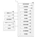
図1は、第1実施形態の超音波診断システム1の機能構成を示すブロック図である。超音波診断システム1は、入出力インターフェース10と、超音波探触子20と、磁気センサ30と、脈拍センサ40と、超音波診断装置100と、を備える。 (First embodiment)
FIG. 1 is a block diagram showing the functional configuration of an ultrasound diagnostic system 1 according to the first embodiment. The ultrasound diagnostic system 1 includes an input/
入出力インターフェース10は、例えば、入力部12と、表示部14と、を備える。入力部12は、例えば、マウス、キーボード、タッチパネルなどの物理的な操作部品を備える。入力部12は、操作者による操作部品の操作量等に基づいて、操作情報、検査対象情報、及び時相領域情報を生成する。 The input/
操作情報は、超音波探触子20の制御に関する情報である。検査対象情報は、超音波探触子20を用いて検査する被検体の対象となる部位(以下、「検査対象部位」という)、例えば「脚部」、「腹部」などの空間的な領域を指定するための情報である。時相領域情報は、検査対象となる時相領域(以下「特定時相領域」という)を設定する範囲を指示する情報である。特定時相領域は、例えば、血管の拡張期と収縮期の繰り返しにおける「拡張期」「拡張期初期」「拡張期から収縮期への移行時」などの時間的な領域である。入力部12は、生成した操作情報、検査対象情報、及び時相領域情報を超音波診断装置100に出力する。 The operation information is information regarding control of the
入力部12はマウス、キーボードなどの物理的な操作部品を備えるものだけに限られない。入力部12は、例えば、装置とは別体に設けられた外部の入力機器から入力操作に対応する電気信号を受け取り、この電気信号を制御回路へ出力する電気信号の処理回路でもよい。 The
表示部14は、例えば、医師や技師などの操作者が視認可能な画像を表示する位置に配置される。表示部14は、超音波診断装置100により出力される情報に基づく画像を表示する。表示部14は、例えば、ディスプレイでもよいし、画像を投影するプロジェクタでもよい。入力部12がタッチパネルである場合、タッチパネルは、表示部14としても機能する。 The
超音波探触子20は、被検体に向けて超音波信号を送信する。超音波探触子20は、被検体に反射した反射エコー信号を受信する。超音波探触子20は、受信した反射エコー信号に基づいて反射波情報を生成する。超音波探触子20は、生成した反射波情報を超音波診断装置100に出力する。 The
磁気センサ30は、例えば、超音波探触子20に敷設されている。磁気センサ30は、超音波探触子20に内蔵されていてもよい。磁気センサ30は、例えば、磁場の変化に基づいて超音波探触子20の位置を検出する。磁気センサ30は、検出した超音波探触子20の位置を位置情報として超音波診断装置100に出力する。 The
脈拍センサ40は、超音波診断装置100に付属して設けられている。脈拍センサ40は、被検体の生体情報としての脈拍情報を取得する。脈拍センサ40は、被検体を検査する際に、被検体の身体、例えば手首に取り付けられる。被検体の身体に取り付けられた脈拍センサ40は、被検体の脈拍を検出する。脈拍センサ40は、検出した脈拍に基づく脈拍情報を超音波診断装置100に出力する。 The
超音波診断装置100は、例えば、送受信回路110と、処理回路120と、を備える。送受信回路110は、入出力インターフェース10や超音波探触子20等のデバイスとの間で各種情報の送受信を行う。さらに、送受信回路110は、例えば、超音波探触子20に送信電圧を付与する。 The ultrasonic
送受信回路110は、超音波探触子20により出力された反射波情報を受信する。送受信回路110は、受信した反射波情報をデジタル信号に変換する。送受信回路110は、デジタル信号に変換した反射波情報を処理回路120に出力する。送受信回路110は、入力部12により出力された操作情報、検査対象情報、及び時相領域情報を受信する。 The transmitting/receiving
送受信回路110は、磁気センサ30により出力された位置情報を受信する。送受信回路110は、脈拍センサ40により出力された脈拍情報を受信する。送受信回路110は、受信した位置情報、脈拍情報、操作情報、検査対象情報、及び時相領域情報を処理回路120に出力する。 The transmitting/receiving
処理回路120は、例えば、取得機能122と、制御機能124と、生成機能126と、位置特定機能128と、時相特定機能130と、設定機能132と、表示制御機能134と、を備える。処理回路120は、例えば、ハードウェアプロセッサが記憶装置(記憶回路)に記憶されたプログラムを実行することにより、これらの機能を実現するものである。 The
ハードウェアプロセッサとは、例えば、CPU(Central Processing Unit)、GPU(Graphics Processing Unit)、特定用途向け集積回路(Application Specific Integrated Circuit; ASIC)、プログラマブル論理デバイス(例えば、単純プログラマブル論理デバイス(Simple Programmable Logic Device; SPLD)または複合プログラマブル論理デバイス(Complex Programmable Logic Device; CPLD)、フィールドプログラマブルゲートアレイ(Field Programmable Gate Array; FPGA)などの回路(circuitry)を意味する。記憶装置にプログラムを記憶させる代わりに、ハードウェアプロセッサの回路内にプログラムを直接組み込むように構成しても構わない。この場合、ハードウェアプロセッサは回路内に組み込まれたプログラムを読み出し実行することで機能を実現する。ハードウェアプロセッサは、単一の回路として構成されるものに限らず、複数の独立した回路を組み合わせて1つのハードウェアプロセッサとして構成され、各機能を実現するようにしてもよい。また、複数の構成要素を1つのハードウェアプロセッサに統合して各機能を実現するようにしてもよい。プログラムは、非一時的(ハードウェアの)記憶媒体に記憶されていてもよい。 Hardware processors include, for example, CPUs (Central Processing Units), GPUs (Graphics Processing Units), Application Specific Integrated Circuits (ASICs), and programmable logic devices (for example, Simple Programmable Logic Devices). Refers to a circuit such as a device (SPLD) or a complex programmable logic device (CPLD), or a field programmable gate array (FPGA).Instead of storing a program in a storage device, The program may be configured to be directly incorporated into the circuit of the hardware processor. In this case, the hardware processor realizes its functions by reading and executing the program incorporated within the circuit. It is not limited to being configured as a single circuit, but may be configured as a single hardware processor by combining multiple independent circuits to realize each function.Also, multiple components may be combined into one hardware processor. Each function may be implemented by being integrated into a hardware processor.The program may be stored in a non-transitory (hardware) storage medium.
取得機能122は、送受信回路110により出力された反射波情報、操作情報、検査対象情報、時相領域情報、位置情報、及び脈拍情報を取得する。取得機能122は、取得した反射波情報を生成機能126に出力する。取得機能122は、取得した操作情報を制御機能124に出力する。取得機能122は、取得した検査対象情報及び時相領域情報を設定機能132に出力する。取得機能122は、取得した位置情報を位置特定機能128に出力する。取得機能122は、取得した脈拍情報を時相特定機能130及び表示制御機能134に出力する。取得機能は、取得部の一例である。 The
制御機能124は、入力部12により出力された操作情報に基づいて、超音波探触子20に送信電圧を特定する。制御機能124は、特定した送信電圧に応じた送受信条件を生成する。制御機能124は、生成した送受信条件に応じた送信電圧を超音波探触子20に対して、送受信回路110のパルサーに付与させる。 The
生成機能126は、超音波探触子20により出力された反射波情報に基づいて、被検体内の画像である超音波画像を生成して。生成機能126は、生成した超音波画像を取得機能122に出力する。取得機能122は、取得した超音波画像を表示制御機能134に出力する。取得機能122は、取得部の一例である。生成機能126が取得部として機能する。制御機能124及び生成機能126は、処理回路120の外部に設けられていてもよい。生成機能126が処理回路120の外部に設けられる場合、生成機能126は、生成した超音波画像を取得機能122に出力する。生成機能126は、取得機能122に代えて、表示制御機能134に超音波画像を出力してもよい。 The
位置特定機能128は、磁気センサ30により出力された位置情報に基づいて、超音波探触子20の位置であり、超音波探触子20が超音波画像を取得した被検体における空間的な位置である取得位置を特定する。位置特定機能128は、特定した取得位置を示す取得位置情報を表示制御機能134に出力する。位置特定機能128は、位置特定部の一例である。 The
時相特定機能130は、脈拍センサ40により出力された脈拍情報に基づいて、超音波画像を生成するための反射エコー信号を超音波探触子20が受信した、時間的な情報としての時相を特定する。時相特定機能130は、特定した時相を示す時相情報を生成して表示制御機能134に出力する。時相特定機能130は、例えば、脈拍情報以外の被検体において周期的または非周期的に変動する情報生体情報、例えば、心拍情報や呼吸情報に基づいて時相を特定してもよい。時相特定機能130は、時相特定部の一例である。 The time
設定機能132は、超音波探触子20により出力された位置情報を用いて位置情報を同期させる。設定機能132は、入力部12により出力された検査対象情報に基づいて、被検体上における検査対象部位の取得範囲を設定する。設定機能132は、複数の取得範囲を操作者に提示して、その中から設定する取得範囲を選択させてもよい。 The
設定機能132は、脈拍センサ40により出力された脈拍情報に基づいて、生体情報である脈拍情報の時間変化を示す時間変化情報を生成し、表示制御機能134に出力する。表示制御機能134は、出力された時間変化情報を可視化して表示部14に表示させる。時間変化情報は、例えば、縦軸を血管の開度とし、横軸を時間とした座標空間における波形で表される。 The
設定機能132は、表示部14に表示された時間変化情報の一部を操作者に指定させることにより、特定時相領域を操作者に設定させる。特定時相領域の時間的な長さは、操作者が調整可能である。入力部12は、表示部14に表示された時間変化情報の一部を操作者が指定可能とされている。入力部12は、操作者が指定した時間変化情報の範囲に基づいて、時相領域情報を生成する。 The
設定機能132は、入力部12により出力された時相領域情報に基づいて、検査対象部位の取得範囲を特定する特定時相領域を設定する。設定機能132は、特定時相領域を1つまたは複数設定する。第1実施形態において、設定機能132は、2つの特定時相領域を設定する。設定機能132は、設定した検査対象部位の取得範囲及び特定時相領域に基づく設定情報を表示制御機能134に出力する。特定時相領域は、設定機能132が設定したものではなく、例えば予め設定された領域でもよく、この場合、例えば、検査対象部位に応じて設定されていてもよく、検査の項目に応じて設定されていてもよい。設定機能132は、複数の特定時相領域を操作者に提示してその中から設定する特定時相領域を選択させてもよい。設定機能132は、設定部の一例である。 The
表示制御機能134は、取得機能122により出力された超音波画像を表示部14に表示させる。表示制御機能134は、入力部12により出力された検査対象情報に基づいて、ボディマークを示す画像を生成して、表示部14に表示させる。ボディマークは、例えば、検査対象部位を模擬的な画像で示す情報である。例えば、検査対象部位が脚部である場合には、表示制御機能134は、脚部を模した画像を表示部14に表示させる。 The
表示制御機能134は、取得機能122により出力された超音波画像に対して、位置特定機能128により出力された取得位置情報に基づく取得位置及び時相特定機能130により出力された時相情報に基づく時相をラベリングする。表示制御機能134は、設定機能132により出力された設定情報に基づいて、超音波画像にラベリングされた時相(以下「ラベリング時相」という)が特定時相領域に含まれるか否を判定する。 The
表示制御機能134は、ラベリング時相が特定時相領域に含まれる場合に、超音波画像にラベリングされた取得位置(以下「ラベリング取得位置」という)に基づいて、超音波画像が取得された被検体における取得位置を特定する。表示制御機能134は、取得位置を特定した後、特定された取得位置に基づいて、超音波画像の取得範囲を特定する。表示制御機能134は、特定した取得範囲を表示部14に表示させる。表示制御機能134は、特定した取得範囲をボディマークの上に重畳表示させる。表示制御機能134は、表示制御部の一例である。 When the labeling time phase is included in a specific time phase region, the
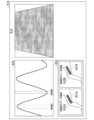
図2は、表示部14が表示する画像の一例を示す図である。表示制御機能134は、ここでは、「時相A」「時相B」の2つの特定時相領域を表示部14に表示させている。「時相A」は、「拡張期」に相当する時相であり、「時相B」は、「収縮期」に相当する時相である。「時相A」の時間的な長さは、「時相B」の時間的な長さよりも長く設定されている。 FIG. 2 is a diagram showing an example of an image displayed by the
表示部14には、超音波画像R10、時間変化画像R20、及び取得範囲表示画像R30が表示される。時間変化画像R20を示す波形における上を向いて凸となる部分は、血管が最も拡張した「拡張期」であり、下を向いて凸となる部分は、血管が最も収縮した「収縮期」である。 The
取得範囲表示画像R30は、第1実施形態では、第1ボディマーク画像R31A及び第2ボディマーク画像R31Bを含む。第1ボディマーク画像R31Aには、第1取得範囲画像R32Aが重畳表示され、第2ボディマーク画像R31Bには第2取得範囲画像R32Bが重畳表示される。第1ボディマーク画像R31Aと第2ボディマーク画像R31Bは同一形状をなす。第1取得範囲画像R32Aは、ラベリング時相が時相A(拡張期)である超音波画像の取得位置を集めた範囲を示す。第2取得範囲画像R32Bは、ラベリング時相が時相B(収縮期)である超音波画像の取得位置を集めた範囲を示す。 In the first embodiment, the acquisition range display image R30 includes a first body mark image R31A and a second body mark image R31B. A first acquisition range image R32A is displayed in a superimposed manner on the first body mark image R31A, and a second acquisition range image R32B is displayed in a superimposed manner on the second body mark image R31B. The first body mark image R31A and the second body mark image R31B have the same shape. The first acquisition range image R32A shows a range in which acquisition positions of ultrasound images whose labeling time phase is time phase A (diastole) are collected. The second acquisition range image R32B shows a range in which acquisition positions of ultrasound images whose labeling time phase is time phase B (systole) are collected.
第1取得範囲画像R32Aは、ラベリング時相が時相A(拡張期)である超音波画像のラベリング取得位置に基づいて生成される画像である。第2取得範囲画像R32Bは、ラベリング時相が時相B(収縮期)である超音波画像のラベリング取得位置に基づいて生成される画像である。以下の説明においては、第1ボディマーク画像R31Aと第2ボディマーク画像R31Bのいずれでもよい場合にボディマーク画像R31とし、第1取得範囲画像R32Aと第2取得範囲画像R32Bのいずれでもよい場合に取得範囲画像R32とする。 The first acquisition range image R32A is an image generated based on the labeling acquisition position of an ultrasound image whose labeling time phase is time phase A (diastole). The second acquisition range image R32B is an image generated based on the labeling acquisition position of the ultrasound image whose labeling time phase is time phase B (systole). In the following description, a body mark image R31 is used when either the first body mark image R31A or the second body mark image R31B is acceptable, and a case where either the first acquisition range image R32A or the second acquisition range image R32B is acceptable is referred to as body mark image R31. It is assumed that the acquired range image R32.
表示制御機能134は、いずれも色付けされた視覚表示で第1取得範囲画像R32A及び第2取得範囲画像R32Bを表示部14に表示させる。表示制御機能134は、ラベリング時相が異なる第1取得範囲画像R32A及び第2取得範囲画像R32Bを表示部14に並んで表示させる。第1取得範囲画像R32Aと第2取得範囲画像R32Bの色は、互いに同色でもよいし、異色でもよい。第1取得範囲画像R32A及び第2取得範囲画像R32Bは、色付け以外の視覚表示、例えば、ハッチングやテクスチャでもよいし、これらを複合的に用いてもよい。 The
次に、超音波診断装置100における処理について、超音波診断を開始する前の処理を説明する。超音波診断を開始するにあたり、表示制御機能134は、操作者の入力部12に対する操作に基づいて設定された取得範囲に対応するボディマーク画像R31を表示部14に表示させるとともに、同期処理を行う。同期処理として、表示制御機能134は、まず位置合わせのために、ボディマーク画像R31の上に原点位置を示す原点画像を表示させる。この状態で、操作者が超音波探触子20を操作して取得位置を原点画像に合わせる。このとき、操作者が、例えば図示しない指定ボタンを押下することで、表示制御機能134は、位置情報を同期する。表示制御機能134は、この同期処理をボディマーク画像R31の上の2点で実行することで、方向を含めた位置同期を完了する。同期処理を実施する点数は、ボディマーク画像R31の形状等によって変動する。 Next, regarding the processing in the ultrasonic
続いて、操作者は、時間変化画像R20に示される周期の一部を指定して、特定時相領域を設定する。時間変化画像R20としては、例えば、1周期以上の脈拍の時間変化を示すグラフが描画されている。操作者は、入力部12を操作することにより、特定時相領域の始点と終点をそれぞれ指定することで、特定時相領域を設定する。第1実施形態において、特定時相領域は2つ設定されている。こうして、操作者は、取得領域及び特定時相領域の設定と同期処理をした後に、超音波診断を開始する。取得領域や特定時相領域は、あらかじめ設定されていてもよい。 Next, the operator specifies a part of the cycle shown in the time-varying image R20 to set a specific time phase region. As the time change image R20, for example, a graph showing a time change in pulse rate over one cycle or more is drawn. The operator sets the specific temporal region by operating the
次に、超音波診断装置100における処理について説明する。図3は、超音波診断装置100の処理の一例を示すフローチャートである。ここでは、同期処理と、取得領域及び特定時相領域の設定が終了した後の処理について説明する。超音波診断装置100は、例えば、超音波探触子20が反射波情報を超音波診断装置100に出力するごとに、図3に示すフローチャートを実行する。超音波診断装置100の生成機能126は、まず、超音波探触子20により出力された反射波情報に基づいて超音波画像を生成し、取得機能122に出力する。取得機能122は、生成機能126により出力された超音波画像を取得する(ステップS101)。 Next, processing in the ultrasound
超音波画像を取得するにあたり、超音波診断装置100は、超音波探触子20に超音波信号を送信させて反射エコー信号を受信させる。超音波診断装置100は、超音波探触子20により出力された反射波情報を取得機能122において取得した反射波情報に基づいて、生成機能126により超音波画像を生成して取得する。超音波診断装置100では、同様の処理を複数回繰り返すことにより、複数の超音波画像を生成して収集する。 In acquiring an ultrasound image, the ultrasound
超音波画像を取得したら、位置特定機能128は、取得位置を特定し、時相特定機能130は、時相を特定する。続いて、表示制御機能134は、位置特定機能128が特定した取得位置及び時相特定機能130が特定した時相を超音波画像にラベリングする(ステップS103)。 After acquiring an ultrasound image, the
続いて、表示制御機能134は、設定機能132により出力された設定情報に基づいて、超音波画像にラベリングされた時相が特定時相領域に含まれるか否かを判定する(ステップS105)。超音波画像にラベリングされた時相が特定時相領域に含まれないと判定した場合、超音波診断装置100は、ステップS115に進む。 Subsequently, the
超音波画像にラベリングされた時相が特定時相領域に含まれると判定した場合、表示制御機能134は、取得した超音波画像にラベリングされた取得位置が、過去に取得した超音波画像(以下「取得済超音波画像」という)のうち、最も近い超音波画像の取得位置との位置のずれを算出する。表示制御機能134は、算出した位置のずれが所定の閾値以下であるか否かを判定する(ステップS107)。 If it is determined that the time phase labeled in the ultrasound image is included in the specific time phase region, the
算出した位置のずれが所定の閾値以下であると判定した場合、表示制御機能134は、今回取得した超音波画像の取得位置と、取得済超音波画像の取得位置の間を取得済とする(ステップS109)。算出した位置のずれが所定の閾値以下でない(閾値を超える)と判定した場合、表示制御機能134は、取得した超音波画像の取得位置を取得済とする(ステップS111)。 If it is determined that the calculated positional deviation is less than or equal to a predetermined threshold, the
続いて、表示制御機能134は、今回取得した超音波画像の取得位置に基づいて、取得した超音波画像にラベリングされた時相に対応する取得範囲画像R32を更新する(ステップS113)。続いて、表示制御機能134は、更新した取得範囲画像R32を、ボディマーク画像R31とともに、表示部14に表示させる。こうして、超音波診断装置100は、図3に示す処理を終了する。 Subsequently, the
第1実施形態の超音波診断装置100において、表示制御機能134は、取得機能122が取得した超音波画像に時相をラベリングし、特定時相領域ごとに超音波画像を取得した位置を算出する。超音波診断装置100は、特定時相領域ごとの超音波画像を取得した位置に基づいて、取得範囲画像R32を生成し、ボディマーク画像R31とともに表示部14に表示させる。このため、操作者は、特定時相領域ごとに超音波画像が不足する領域を容易に認識することができるので、超音波画像が不足する時相を容易に認識することができる。したがって、画像の時空間的な収集状況を確認することができる。 In the ultrasound
第1実施形態の超音波診断装置100では、超音波探触子20に設けられたセンサである磁気センサ30の検出結果に基づいて、取得位置を特定する。このため、取得位置を特定するために別途部材を設けることなく、取得位置を容易に特定することができる。 In the ultrasound
第1実施形態の超音波診断装置100において、時相特定機能130は、脈拍センサ40により出力された脈拍情報に基づいて、超音波探触子20が超音波画像を取得した時相を特定する。このため、超音波画像を取得した時相を容易に特定することができる。 In the ultrasound
第1実施形態の超音波診断装置100において、設定機能132は、入力部12により出力された時相領域情報に基づいて、時相を特定するための特定時相領域を設定する。このため、特定時相領域を容易に設定することができる。 In the ultrasound
第1実施形態の超音波診断装置100において、表示制御機能134は、ボディマーク画像R31を表示部14に表示させ、ボディマーク画像R31の上に取得範囲画像R32を重畳表示させる。このため、ボディマーク画像R31の上における超音波画像の取得状況を分かりやすく表示することができる。 In the ultrasound
第1実施形態の超音波診断装置100において、表示制御機能134は、ラベリング時相が異なる第1取得範囲画像R32A及び第2取得範囲画像R32Bを表示部14に並んで表示させる。このため、混同しにくいようにして取得範囲画像を操作者に認識させることができる。 In the ultrasound
第1実施形態の超音波診断装置100では、脈拍センサ40を用いて時相を検出して特定するが、時相は他の検出手段などで検出して特定してもよい。例えば、被検体の心拍を検出する心拍センサを用いてもよい。あるいは、被検体の心周期を測定したり予め測定して記憶しておいたりして、超音波診断を介する開始点を測定した後、被検体の心周期を用いて時相を特定してもよい。これらの装置を用いることにより、超音波画像を取得する時相を多様な形で特定することができる。 In the ultrasonic
第1実施形態では、取得範囲画像をボディマーク画像R31に重畳表示させるが、ボディマーク画像R31以外に表示させてもよく、例えば、被検体のリファレンス画像を撮像し、撮像したリファレンス画像に取得範囲画像を重畳表示させてもよい。リファレンス画像は、例えば、CT(Computed Tomography)画像、MR(Magnetic Resonance)画像、UL(ultrasonography)画像、写真画像でよい。取得範囲画像は、ボディマーク画像R31等に重畳させることなく表示させてもよいし、ボディマーク画像R31等を表示させることなく取得範囲画像を表示させてもよい。リファレンス画像等を利用することにより、ボディマーク画像R31を作成しないで済ませることができる。 In the first embodiment, the acquisition range image is superimposed and displayed on the body mark image R31, but it may be displayed on other than the body mark image R31. For example, a reference image of the subject is captured, and the acquisition range image is added to the captured reference image. Images may be displayed in a superimposed manner. The reference image may be, for example, a CT (Computed Tomography) image, an MR (Magnetic Resonance) image, a UL (Ultrasonography) image, or a photographic image. The acquisition range image may be displayed without being superimposed on the body mark image R31 or the like, or the acquisition range image may be displayed without displaying the body mark image R31 or the like. By using a reference image or the like, it is possible to avoid creating the body mark image R31.
表示制御機能134は、操作者による入力部12の操作により、表示部14に表示される取得範囲画像を拡大して表示するようにしてもよい。表示部14に複数の取得範囲画像R32が表示される場合において、表示制御機能134は、複数の取得範囲画像R32のうちの1を指定する操作者による入力部12の操作があったときに、指定された画像を拡大指定表示するようにしてもよい。 The
第1実施形態において、特定時相領域は2つ設定されるが、特定時相領域は、1つのみ設定されてもよいし、2以上設定されてもよい。特定時相領域が2以上設定される場合、表示制御機能134は、全ての特定時相領域に対する取得範囲を表示部14に表示させてもよいし、一部の特定時相領域に対する取得範囲を表示部14に表示させてもよい。 In the first embodiment, two specific time phase regions are set, but only one specific time phase region may be set, or two or more specific time phase regions may be set. When two or more specific time-phase regions are set, the
(第2実施形態)
次に、第2実施形態の超音波診断装置100について説明する。第2実施形態の超音波診断装置100は、第1実施形態と比較して、表示制御機能134が表示部14に表示させる画像が主に異なる。以下、第1実施形態との相違点を中心として、第2実施形態について説明する。図4は、第2実施形態の表示部14が表示する画像の一例を示す図である。図4では、表示部14に表示される時間変化画像R20及び取得範囲表示画像R30を示し、超音波画像R10の表示を省略している。 (Second embodiment)
Next, an ultrasound
第2実施形態の超音波診断装置100において、図1に示す表示制御機能134は、第1実施形態と同様、表示部14に時間変化画像R20及び取得範囲表示画像R30を表示させる。第2実施形態の超音波診断装置100において、表示制御機能134は、ここでは、時間変化画像R20「時相X」「時相Y」の2つの特定時相領域を含んで表示部14に表示させている。「時相X」は、「時相Y」よりも短く、「時相Y」は「時相X」を含む関係にある。 In the ultrasound
第2実施形態の超音波診断装置100において、取得範囲表示画像R30は、ボディマーク画像R31と、第1取得範囲画像R32Xと、第2取得範囲画像R32Yと、を含む。第1実施形態では、第1取得範囲画像R32Aと第2取得範囲画像R32Bが独立し、それぞれ第1ボディマーク画像R31A及び第2ボディマーク画像R31Bの上に重畳表示されているが、第2実施形態では、第1取得範囲画像R32Xと第2取得範囲画像R32Yが重畳して表示される。表示制御機能134は、複数の取得範囲画像R32を重畳して表示させる場合に、全ての取得範囲画像R32をボディマーク画像R31の上に重畳表示させてもよいし、一部の特定時相領域に対する取得範囲画像R32をボディマーク画像R31の上に重畳表示させてもよい。 In the ultrasound
第1取得範囲画像R32Xは、ラベリング時相が「時相X」である超音波画像のラベリング取得位置に基づいて生成される画像である。第2取得範囲画像R32Yは、ラベリング時相が「時相Y」である超音波画像のラベリング取得位置に基づいて生成される画像である。 The first acquisition range image R32X is an image generated based on the labeling acquisition position of the ultrasound image whose labeling time phase is "time phase X." The second acquisition range image R32Y is an image generated based on the labeling acquisition position of the ultrasound image whose labeling time phase is “time phase Y”.
表示制御機能134は、第1取得範囲画像R32Xを例えば赤色で表示し、第2取得範囲画像R32Yを青色で表示する。このように、表示制御機能134は、重畳させる第1取得範囲画像R32X及び第2取得範囲画像R32Yの視覚表示が、互いに異なる視覚表示となるようにしている。 The
第2実施形態の超音波診断装置100は、第1実施形態の超音波診断装置100と同様の作用効果を奏する。第2実施形態の超音波診断装置100は、取得範囲表示画像R30において、第1取得範囲画像R32Xと第2取得範囲画像R32Yが重畳して表示される。このため、検査者は第1取得範囲画像R32Xと第2取得範囲画像R32Yとを比較可能な状態で認識できるとともに、取得範囲表示画像R30を表示するスペースを抑制することができる。 The ultrasonic
(第3実施形態)
次に、第3実施形態の超音波診断装置100について説明する。第3実施形態の超音波診断装置100は、第1実施形態と比較して、表示制御機能134が表示部14に表示させる画像が主に異なる。以下、第1実施形態との相違点を中心として、第3実施形態について説明する。図5は、第3実施形態の超音波診断装置100における表示部14が表示する画像の一例を示す図である。図5では、表示部14に表示される取得範囲表示画像R30を示し、超音波画像R10及び時間変化画像R20の表示を省略している。 (Third embodiment)
Next, an ultrasonic
第3実施形態の超音波診断装置100において、表示制御機能134は、取得範囲画像内の位置における超音波画像の収集率を算出する。表示制御機能134は、取得範囲画像内の位置ごとの超音波画像の収集率に応じて、取得範囲画像R33の表示形態を調整する。収集率とは、例えば、単位領域における超音波画像が取得された領域の割合を示す。取得範囲表示画像R30は、ボディマーク画像R31と、取得範囲画像R33と、を含む。取得範囲画像R33は、例えば、表示位置によって濃淡が変動する画像である。 In the ultrasound
取得範囲画像R33においては、図5に示すように、濃く表示された部分における超音波画像の収集率が高く、薄く表示された部分における超音波画像の収集率が高い。取得範囲画像R33は、グラデーションをもって表示される。取得範囲画像は、収集率毎に区切られて表示されてもよい。図5では、取得範囲画像R33に示される取得範囲における左下方の部位における超音波画像の収集率が高く、右上に行くほど超音波画像の取得率が低くなっている。 In the acquisition range image R33, as shown in FIG. 5, the collection rate of ultrasound images is high in the darkly displayed portions, and the collection rate of ultrasound images is high in the lightly displayed portions. The acquisition range image R33 is displayed with gradation. The acquisition range images may be divided and displayed for each collection rate. In FIG. 5, the acquisition rate of ultrasound images is high in the lower left part of the acquisition range shown in the acquisition range image R33, and the acquisition rate of ultrasound images becomes lower toward the upper right.
第3実施形態の超音波診断装置100は、第1実施形態の超音波診断装置100と同様の作用効果を奏する。第3実施形態の超音波診断装置100は、超音波画像の収集率に応じて、取得範囲画像R33の表示形態を調整する。このため、超音波画像の収集率が低い位置を操作者が容易に把握することができる。 The ultrasonic
(第4実施形態)
次に、第4実施形態の超音波診断装置100について説明する。図6は、第4実施形態の超音波診断装置100における表示部14が表示する画像の一例を示す図である。図6では、表示部14に表示される取得範囲表示画像R30を示し、超音波画像R10及び時間変化画像R20の表示を省略している。 (Fourth embodiment)
Next, an ultrasonic
第4実施形態の超音波診断装置100において、取得機能122は、磁気センサ30により出力された位置情報を表示制御機能134に出力する。表示制御機能134は、取得機能122により出力された位置情報に基づいて、ボディマーク画像R31に対する超音波探触子20の位置及び超音波探触子20の中心位置を特定する。 In the ultrasound
表示制御機能134は、ボディマーク画像R31及び取得範囲画像R32のほか、特定した超音波探触子20の位置を示す探触子位置画像R50及び超音波探触子20の中心位置を示す探触子中心位置画像R51を表示部14に表示させる。探触子位置画像R50は、例えば、超音波探触子20の送受信面の面積に相当する面積の領域を囲んで表示される。探触子中心位置画像R51は、例えば、表示部14に表示される探触子位置画像R50における重心位置に配置され、例えば、バツ印で表示される。 In addition to the body mark image R31 and the acquisition range image R32, the
第4実施形態の超音波診断装置100は、第1実施形態の超音波診断装置100と同様の作用効果を奏する。第4実施形態の超音波診断装置100において、表示制御機能134は、超音波探触子20の位置を示す探触子位置画像R50及びその中心位置を示す探触子中心位置画像R51を、ボディマーク画像R31及び取得範囲画像R32とともに表示部14に表示させる。このため、超音波画像を撮像できていない被検体の位置と超音波探触子20との位置関係を操作者に容易に認識させることができる。したがって、超音波画像の収集をスムーズに進行させることができる。 The ultrasonic
(第5実施形態)
次に、第5実施形態の超音波診断装置100について説明する。図7は、第5実施形態の超音波診断システム1の機能構成を示すブロック図である。第5実施形態の超音波診断システム1において、超音波診断装置100は、処理回路120が速度検出機能136を備える。 (Fifth embodiment)
Next, an ultrasonic
速度検出機能136は、生成機能126が生成した超音波画像の特定位置をマーキングし、マーキングした特定位置の時間変化に基づいて、超音波探触子20の移動速度を検出する。この場合、超音波診断装置100は、例えば、超音波画像を解析することで特定位置をマーキングしてよい。超音波探触子20の速度は、超音波探触子20の送り速度である。速度検出機能136は、検出部の一例である。 The
速度検出機能136は、検出した超音波探触子20の移動速度を表示制御機能134に出力する。表示制御機能134は、速度検出機能136により出力された超音波探触子20の速度に基づいて、取得範囲画像内の位置における超音波画像を取得した際の超音波探触子20の移動速度(以下、「撮像時移動速度」という)を特定する。表示制御機能134は、取得範囲画像内の位置ごとの撮像時移動速度に応じて、取得範囲画像R35の表示形態を調整する。 The
図8は、第5実施形態の超音波診断装置100における表示部14が表示する画像の一例を示す図である。取得範囲表示画像R30は、ボディマーク画像R31と、取得範囲画像R35と、を含む。取得範囲画像R35は、例えば、表示位置によって取得範囲画像の色や濃淡などの視覚表示が変動する画像である。 FIG. 8 is a diagram showing an example of an image displayed by the
取得範囲画像R35においては、図8示すように、例えば第1色、例えば赤色で濃く表示された部分では撮像時移動速度が速く、例えば第2色、例えば青色で濃く表示された部分では撮像時移動速度が遅い。撮像時移動速度が速い状態では、遅くなるほど色が薄く、撮像時移動速度が遅い状態では、早くなるほど色が薄くなるようにグラデーションをもって表示される。図8では、取得範囲画像R35に示される取得範囲における左下方の部位における撮像時移動速度が速く、右上に行くほど撮像時移動速度が遅くなっている。撮像時移動速度は、速度毎に区切られて表示されてもよい。撮像時移動速度は、単色で表示されてもよい。 In the acquisition range image R35, as shown in FIG. 8, for example, the moving speed at the time of imaging is fast in the part displayed darkly in the first color, for example red, and the moving speed at the time of imaging is fast in the part displayed darkly in the second color, for example blue. Movement speed is slow. When the moving speed during imaging is fast, the slower the moving speed, the lighter the color becomes. When the moving speed during imaging is slower, the faster the moving speed is, the lighter the color is. In FIG. 8, the moving speed at the time of imaging is fast in the lower left part of the acquisition range shown in the acquisition range image R35, and the moving speed at the time of imaging becomes slower toward the upper right. The moving speed at the time of imaging may be displayed divided by speed. The moving speed at the time of imaging may be displayed in a single color.
第5実施形態の超音波診断装置100は、第1実施形態の超音波診断装置100と同様の作用効果を奏する。第5実施形態の超音波診断装置100は、撮像時移動速度に応じて、取得範囲画像R33の表示形態を調整する。このため、取得範囲画像内における撮像時移動速度が速い領域と遅い領域を操作者が容易に把握することができる。 The ultrasonic
第5実施形態では、速度検出機能136により、超音波探触子20の移動速度を検出するが、超音波探触子20の移動速度は、他の検出手段などで検出してもよい。例えば、超音波探触子20に設けられた速度センサを用いてもよいし、超音波探触子20を含む光学画像を撮像するカメラなどを別途設け、このカメラで撮像した画像を画像処理することにより超音波探触子20の移動速度を検出してもよい。 In the fifth embodiment, the
(第6実施形態)
次に、第6実施形態の超音波診断装置100について説明する。第6実施形態の超音波診断装置100は、例えば、取得機能122が取得した超音波画像に基づいて、超音波探触子20の位置を検出する。この場合、超音波診断装置100は、例えば、超音波画像を解析することで被検体の体の部位等を特定し、特定した体の部位の位置に応じて、超音波探触子20の位置を検出する。以下に、第6実施形態の超音波診断装置100において、超音波画像に取得位置及び時相をラベリングするまでの処理について説明する。 (Sixth embodiment)
Next, an ultrasonic
図9は、第6実施形態の超音波診断装置100の処理の一例を示すフローチャートである。超音波診断装置100は、例えば、超音波探触子20が反射波情報を超音波診断装置100に出力するごとに、図9に示すフローチャートを実行する。第6実施形態の超音波診断装置100は、まず、生成機能126において、超音波探触子20により出力された反射波情報に基づいて、超音波画像を生成し(ステップS201)、取得機能122に出力する。取得機能122は、取得した超音波画像を記憶装置に格納する。記憶装置は、超音波診断装置100が超音波画像の取得を開始してから以後に取得機能122が取得した超音波画像を記憶している。 FIG. 9 is a flowchart showing an example of processing of the ultrasound
続いて、生成機能126は、超音波画像を解析して超音波画像内に血管を探索し、探索した血管の血管径を計測する(ステップS203)。続いて、生成機能126は、前回に生成機能126が取得した超音波画像との比較における血管の位置や血管径の変化に基づいて、超音波画像内の特定位置のずれを検出する(ステップS205)。続いて、生成機能126が検出した特定位置のずれに基づいて、位置特定機能128は超音波画像の取得位置を推定し、時相特定機能130は、超音波画像を生成するための反射エコー信号を超音波探触子20が受信した時相を推定する(ステップS207)。 Next, the
その後、超音波診断装置100は、表示制御機能134において、位置特定機能128が推定した取得位置及び時相特定機能130が推定した時相を、取得機能122が取得した超音波画像にラベリングする(ステップS209)。こうして、超音波診断装置100は、図9に示す処理を終了する。 Thereafter, the ultrasound
第6実施形態の超音波診断装置100は、超音波探触子20により出力された反射波情報から生成した超音波画像に基づいて、超音波画像の取得位置及び時相を推定して超音波画像にラベリングする。このため、取得位置を検出するための磁気センサ30などを設ける必要が無くなり、装置の簡素化に寄与することができる。 The ultrasound
(第7実施形態)
次に、第7実施形態の超音波診断装置100について説明する。図10は、第7実施形態の超音波診断システム1の機能構成を示すブロック図である。第7実施形態の超音波診断装置100では、第6実施形態の超音波診断装置100と同様に、生成機能126は、取得した超音波画像を記憶装置に格納して収集する。第7実施形態の超音波診断装置100は、例えば、収集した複数の超音波画像に基づいて、合成画像を作成する。 (Seventh embodiment)
Next, an ultrasonic
合成画像を作成する際には、合成画像を作成するための作成条件を満たす必要がある。第7実施形態の超音波診断装置100は、判定機能138を備える。超音波診断装置100は、作成条件を記憶装置に格納しており、判定機能138は、取得機能122が取得して収集した複数の超音波画像により、合成画像を作成するための作成条件が満たされるか否かを判定する。判定機能138は、特定時相領域ごとにそれぞれ作成条件を判定する。判定機能138は、判定部の一例である。 When creating a composite image, it is necessary to satisfy creation conditions for creating the composite image. The ultrasonic
判定機能138は、生成機能126が生成して取得機能122が取得して収集された複数の超音波画像に基づいて、合成画像を作成するために必要となる取得位置の超音波画像を全て取集しているか否かを判定する。作成条件が満たされないと判定機能が判定した場合、表示制御機能134は、作成条件を満たすために不足している取得範囲(以下、「不足範囲」という)を特定する。表示制御機能134は、不足範囲を可視化して表示部14に表示させる。 The
図11は、第7実施形態の表示部14が表示する画像の一例を示す図である。表示制御機能134は、取得範囲画像R40とともに、不足範囲画像R60を表示する。不足範囲画像R60は、取得範囲画像R40と明確に区切られて表示されている。不足範囲画像R60は、取得範囲画像R40との間でグラデーションをもって表示されてもよい。 FIG. 11 is a diagram showing an example of an image displayed by the
例えば、血管の合成画像を作成しようとする際に、血管の一端、中間、他端をそれぞれ含む超音波画像を必要であるとする。このとき、取得機能122が、血管の一端及び他端の超音波画像については取得済であるが、血管の中間の超音波画像を取得していないとする。この場合には、表示制御機能134は、血管の一端及び他端の部分に取得範囲画像R40を重畳させ、中間の部分に不足範囲画像を重畳させて表示部14に表示させる。表示制御機能134は、合成画像を作成する上で必要な密度で超音波画像が収集できている領域がある場合に、その領域に拡張して収集範囲を表示するようにしてもよい。 For example, suppose that when attempting to create a composite image of a blood vessel, ultrasound images including one end, middle, and other end of the blood vessel are required. At this time, it is assumed that the
第7実施形態の超音波診断装置100は、表示制御機能134により、合成画像を作成するために必要となる超音波画像を取得するための取得範囲を表示部14に表示させる。このため、合成画像を作成するために必要となる超音波画像を容易に取得することができる。さらには、超音波画像の収集状況を知らせることができるとともに、超音波画像の収集漏れを防ぐことができる。 The ultrasound
(第8実施形態)
次に、第8実施形態の超音波診断装置100について説明する。図12は、第8実施形態の超音波診断システム1の機能構成を示すブロック図である。第8実施形態の超音波診断システム1は、超音波探触子20を撮像するカメラ50を備え、図1に示す磁気センサ30を備えていない。超音波診断装置100は、位置検出機能140を備える。カメラ50は、撮像部の一例である。 (Eighth embodiment)
Next, an ultrasound
カメラ50は、超音波探触子20を含む光学画像を撮像する。カメラ50は、撮像した光学画像を超音波診断装置100に出力する。超音波診断装置100における位置検出機能140は、カメラ50により出力された光学画像を画像処理することにより、超音波探触子20の位置を検出する。位置検出機能140は、取得した超音波探触子20の位置を位置特定機能128に出力する。 The
第8実施形態の超音波診断装置100は、超音波探触子20を撮像するカメラ50により出力された光学画像に基づいて、超音波探触子20の位置を検出する。このため、超音波探触子20に磁気センサ30などを設ける必要がないので、超音波探触子20の重量の増大を抑制することができ、超音波探触子20を取り回しやすくすることができる。 The ultrasound
以上説明した少なくとも1つの実施形態によれば、超音波探触子から送信された超音波信号が被検体で反射された反射エコー信号に基づく前記被検体の画像を取得する取得部と、前記画像を取得した前記被検体における取得位置を特定する位置特定部と、前記画像を取得した時相を特定する時相特定部と、特定された前記取得位置および前記時相に基づいて、少なくとも1つの特定時相領域における前記被検体上の前記画像の取得範囲を表示部に表示させる表示制御部と、を持つことにより、画像の時空間的な収集状況を確認することができる。 According to at least one embodiment described above, an acquisition unit that acquires an image of the subject based on a reflected echo signal obtained by reflecting an ultrasound signal transmitted from an ultrasound probe on the subject; a position specifying unit that specifies the acquisition position in the subject where the image was acquired; a time phase specifying unit that specifies the time phase at which the image was acquired; and at least one By including a display control unit that causes a display unit to display an acquisition range of the image on the subject in a specific time phase region, it is possible to check the spatiotemporal acquisition status of images.
いくつかの実施形態を説明したが、これらの実施形態は、例として提示したものであり、発明の範囲を限定することは意図していない。これら実施形態は、その他の様々な形態で実施されることが可能であり、発明の要旨を逸脱しない範囲で、種々の省略、置き換え、変更を行うことができる。これら実施形態やその変形は、発明の範囲や要旨に含まれると同様に、特許請求の範囲に記載された発明とその均等の範囲に含まれるものである。 Although several embodiments have been described, these embodiments are presented by way of example and are not intended to limit the scope of the invention. These embodiments can be implemented in various other forms, and various omissions, substitutions, and changes can be made without departing from the gist of the invention. These embodiments and their modifications are included within the scope and gist of the invention as well as within the scope of the invention described in the claims and its equivalents.
1 超音波診断システム
10 入出力インターフェース
12 入力部
14 表示部
20 超音波探触子
30 磁気センサ
40 脈拍センサ
100 超音波診断装置
110 送受信回路
120 処理回路
122 取得機能
124 制御機能
126 生成機能
128 位置特定機能
130 時相特定機能
132 設定機能
134 表示制御機能
R10 超音波画像
R20 時間変化画像
R30 取得範囲表示画像
R31 ボディマーク画像
R32,R33,R35 取得範囲画像1 Ultrasonic
Claims (16)
Translated fromJapanese前記画像を取得した前記被検体における取得位置を特定する位置特定部と、
前記画像を取得した時相を特定する時相特定部と、
特定された前記取得位置および前記時相に基づいて、少なくとも1つの特定時相領域における前記被検体上の前記画像の取得範囲を表示部に表示させる表示制御部と、を備える
超音波診断装置。 an acquisition unit that acquires an image of the subject based on a reflected echo signal obtained by reflecting an ultrasound signal transmitted from an ultrasound probe on the subject;
a position specifying unit that specifies an acquisition position in the subject from which the image is acquired;
a time phase identification unit that identifies the time phase in which the image was acquired;
An ultrasonic diagnostic apparatus, comprising: a display control unit that causes a display unit to display an acquisition range of the image on the subject in at least one specific time phase region based on the specified acquisition position and the time phase.
請求項1に記載に超音波診断装置。 The ultrasonic diagnostic apparatus according to claim 1, wherein the position specifying unit specifies the acquisition position based on a detection result of a sensor provided in the ultrasonic probe.
請求項1に記載の超音波診断装置。 The ultrasonic diagnostic apparatus according to claim 1, wherein the position specifying unit specifies the acquisition position based on the image acquired by the acquisition unit.
前記位置特定部は、前記撮像部が撮像した画像に基づいて、前記取得位置を特定する
請求項1に記載の超音波診断装置。 further comprising an imaging unit that captures an image of the ultrasound probe,
The ultrasound diagnostic apparatus according to claim 1, wherein the position specifying unit specifies the acquisition position based on an image captured by the imaging unit.
請求項1から4のうちいずれか1項に記載の超音波診断装置。 The ultrasonic diagnostic apparatus according to any one of claims 1 to 4, wherein the time phase identifying unit identifies the time phase based on biological information regarding a heartbeat or pulse of the subject.
請求項1から4のうちいずれか1項に記載の超音波診断装置。 The ultrasonic diagnostic apparatus according to any one of claims 1 to 4, wherein the time phase identifying unit identifies the time phase based on information regarding the cardiac cycle of the subject.
請求項1から6のうちいずれか1項に記載の超音波診断装置。 further comprising a setting unit that sets the specific time phase region;
The ultrasonic diagnostic apparatus according to any one of claims 1 to 6.
前記ボディマークの上に前記取得範囲を視覚表示させる
請求項1から7のうちいずれか1項に記載の超音波診断装置。 The display control unit displays a body mark on the display unit,
The ultrasonic diagnostic apparatus according to any one of claims 1 to 7, wherein the acquisition range is visually displayed on the body mark.
前記リファレンス画像の上に前記取得範囲を視覚表示させる
請求項1から7のうちいずれか1項に記載の超音波診断装置。 The display control unit displays a reference image on the display unit,
The ultrasonic diagnostic apparatus according to any one of claims 1 to 7, wherein the acquisition range is visually displayed on the reference image.
請求項1から9のうちいずれか1項に記載の超音波診断装置。 The ultrasonic diagnostic apparatus according to any one of claims 1 to 9, wherein the display control unit displays the plurality of acquisition ranges in which the specific time phase regions are different from each other side by side on the display unit.
請求項1から9のうちいずれか1項に記載の超音波診断装置。 The ultrasonic diagnostic apparatus according to any one of claims 1 to 9, wherein the display control unit displays the plurality of acquisition ranges in which the specific time phase regions are different from each other in a superimposed manner.
請求項1から11のうちいずれか1項に記載の超音波診断装置。 The ultrasonic diagnostic apparatus according to any one of claims 1 to 11, wherein the display control unit adjusts the display form of the acquisition range according to the acquisition rate of the images.
前記表示制御部は、前記位置特定部が取得した前記超音波探触子の位置を、前記取得範囲に重畳させて表示させる
請求項1から12のうちいずれか1項に記載の超音波診断装置。 The position specifying unit specifies the position of the ultrasound probe,
The ultrasonic diagnostic apparatus according to any one of claims 1 to 12, wherein the display control unit displays the position of the ultrasound probe acquired by the position specifying unit in a manner superimposed on the acquisition range. .
前記表示制御部は、前記検出部が検出した移動速度に応じて、前記取得範囲の表示形態を調整する
請求項1から13のうちいずれか1項に記載の超音波診断装置。 Further comprising a detection unit that detects a moving speed of the ultrasound probe when acquiring the image,
The ultrasonic diagnostic apparatus according to any one of claims 1 to 13, wherein the display control unit adjusts the display form of the acquisition range according to the moving speed detected by the detection unit.
前記表示制御部は、前記作成条件が満たされないと前記判定部が判定した場合に、前記作成条件を満たすために必要な前記取得範囲を前記表示部に表示させる
請求項1から14のうちいずれか1項に記載の超音波診断装置。 further comprising a determination unit that determines whether a creation condition for creating a composite image is satisfied by the plurality of images acquired and collected by the acquisition unit,
The display control unit causes the display unit to display the acquisition range necessary to satisfy the creation condition when the determination unit determines that the creation condition is not satisfied. The ultrasonic diagnostic device according to item 1.
超音波探触子から送信された超音波信号が被検体で反射された反射エコー信号に基づく前記被検体の画像を取得させ、
前記画像を取得した前記被検体における取得位置を特定させ、
前記画像を取得した特定時相領域を特定させ、
前記特定時相領域における前記画像の取得範囲を表示部に表示させる
プログラム。 For ultrasound diagnostic equipment,
acquiring an image of the subject based on a reflected echo signal obtained by reflecting an ultrasound signal transmitted from an ultrasound probe on the subject;
specifying the acquisition position in the subject where the image was acquired;
specifying a specific temporal region in which the image was acquired;
A program that causes a display unit to display an acquisition range of the image in the specific time phase region.
Priority Applications (3)
| Application Number | Priority Date | Filing Date | Title |
|---|---|---|---|
| JP2020128074AJP7434095B2 (en) | 2020-07-29 | 2020-07-29 | Ultrasonic diagnostic equipment and programs |
| US17/305,603US20220031285A1 (en) | 2020-07-29 | 2021-07-12 | Ultrasonic diagnostic apparatus and storage medium |
| CN202110848547.7ACN114052784B (en) | 2020-07-29 | 2021-07-27 | Ultrasonic diagnostic device and storage medium |
Applications Claiming Priority (1)
| Application Number | Priority Date | Filing Date | Title |
|---|---|---|---|
| JP2020128074AJP7434095B2 (en) | 2020-07-29 | 2020-07-29 | Ultrasonic diagnostic equipment and programs |
Publications (2)
| Publication Number | Publication Date |
|---|---|
| JP2022025322A JP2022025322A (en) | 2022-02-10 |
| JP7434095B2true JP7434095B2 (en) | 2024-02-20 |
Family
ID=80002501
Family Applications (1)
| Application Number | Title | Priority Date | Filing Date |
|---|---|---|---|
| JP2020128074AActiveJP7434095B2 (en) | 2020-07-29 | 2020-07-29 | Ultrasonic diagnostic equipment and programs |
Country Status (3)
| Country | Link |
|---|---|
| US (1) | US20220031285A1 (en) |
| JP (1) | JP7434095B2 (en) |
| CN (1) | CN114052784B (en) |
Citations (4)
| Publication number | Priority date | Publication date | Assignee | Title |
|---|---|---|---|---|
| JP2007236823A (en) | 2006-03-10 | 2007-09-20 | Toshiba Corp | Ultrasonic diagnostic equipment |
| JP2008167838A (en) | 2007-01-10 | 2008-07-24 | Hitachi Medical Corp | Ultrasonic diagnostic apparatus and method of displaying ultrasonic image |
| JP2011521762A (en) | 2008-06-05 | 2011-07-28 | コーニンクレッカ フィリップス エレクトロニクス エヌ ヴィ | Ultrasound imaging of extended field of view with 2D array probe |
| WO2012073164A1 (en) | 2010-12-03 | 2012-06-07 | Koninklijke Philips Electronics N.V. | Device and method for ultrasound imaging |
Family Cites Families (18)
| Publication number | Priority date | Publication date | Assignee | Title |
|---|---|---|---|---|
| JP4258014B2 (en)* | 2002-06-04 | 2009-04-30 | 株式会社日立メディコ | Ultrasonic diagnostic equipment |
| JP5738507B2 (en)* | 2006-01-19 | 2015-06-24 | 東芝メディカルシステムズ株式会社 | Ultrasonic probe trajectory expression device and ultrasonic diagnostic device |
| JP2007195882A (en)* | 2006-01-30 | 2007-08-09 | Toshiba Corp | Ultrasonic diagnostic equipment |
| JP2008073304A (en)* | 2006-09-22 | 2008-04-03 | Gifu Univ | Ultrasonic breast diagnosis system |
| JP5240994B2 (en)* | 2008-04-25 | 2013-07-17 | 東芝メディカルシステムズ株式会社 | Ultrasonic diagnostic apparatus, ultrasonic image processing apparatus, and ultrasonic image processing program |
| JP5395396B2 (en)* | 2008-10-15 | 2014-01-22 | 株式会社東芝 | Ultrasonic diagnostic apparatus, medical image processing apparatus, and medical image processing program |
| JP5284123B2 (en)* | 2009-01-20 | 2013-09-11 | 株式会社東芝 | Ultrasonic diagnostic apparatus and position information acquisition program |
| US20100286518A1 (en)* | 2009-05-11 | 2010-11-11 | General Electric Company | Ultrasound system and method to deliver therapy based on user defined treatment spaces |
| CN102548483B (en)* | 2009-12-04 | 2015-04-01 | 柯尼卡美能达株式会社 | Ultrasonic diagnostic device |
| JP5689662B2 (en)* | 2009-12-09 | 2015-03-25 | 株式会社東芝 | Ultrasonic diagnostic apparatus, ultrasonic image processing apparatus, ultrasonic image processing program, medical image diagnostic apparatus, medical image processing apparatus, and medical image processing program |
| US9474505B2 (en)* | 2012-03-16 | 2016-10-25 | Toshiba Medical Systems Corporation | Patient-probe-operator tracking method and apparatus for ultrasound imaging systems |
| JP2014121594A (en)* | 2012-11-22 | 2014-07-03 | Toshiba Corp | Ultrasonic diagnostic apparatus, image processing apparatus, and image processing method |
| KR101462174B1 (en)* | 2013-01-29 | 2014-11-20 | 삼성전자주식회사 | image display apparatus and method for display images |
| EP3125768B1 (en)* | 2014-03-31 | 2019-10-30 | Koninklijke Philips N.V. | Haptic feedback for ultrasound image acquisition |
| JP6486028B2 (en)* | 2014-07-23 | 2019-03-20 | 株式会社日立製作所 | Ultrasonic diagnostic apparatus and method of operating ultrasonic diagnostic apparatus |
| KR102764213B1 (en)* | 2016-06-30 | 2025-02-07 | 인튜어티브 서지컬 오퍼레이션즈 인코포레이티드 | Graphical user interface for displaying guidance information in a plurality of modes during an image-guided procedure |
| US20180192996A1 (en)* | 2017-01-10 | 2018-07-12 | Canon Medical Systems Corporation | Ultrasonic diagnostic device, image processing device, and image processing method |
| JP6965049B2 (en)* | 2017-07-14 | 2021-11-10 | キヤノンメディカルシステムズ株式会社 | Medical diagnostic imaging equipment, medical information processing equipment and medical information processing programs |
- 2020
- 2020-07-29JPJP2020128074Apatent/JP7434095B2/enactiveActive
- 2021
- 2021-07-12USUS17/305,603patent/US20220031285A1/ennot_activeAbandoned
- 2021-07-27CNCN202110848547.7Apatent/CN114052784B/enactiveActive
Patent Citations (4)
| Publication number | Priority date | Publication date | Assignee | Title |
|---|---|---|---|---|
| JP2007236823A (en) | 2006-03-10 | 2007-09-20 | Toshiba Corp | Ultrasonic diagnostic equipment |
| JP2008167838A (en) | 2007-01-10 | 2008-07-24 | Hitachi Medical Corp | Ultrasonic diagnostic apparatus and method of displaying ultrasonic image |
| JP2011521762A (en) | 2008-06-05 | 2011-07-28 | コーニンクレッカ フィリップス エレクトロニクス エヌ ヴィ | Ultrasound imaging of extended field of view with 2D array probe |
| WO2012073164A1 (en) | 2010-12-03 | 2012-06-07 | Koninklijke Philips Electronics N.V. | Device and method for ultrasound imaging |
Also Published As
| Publication number | Publication date |
|---|---|
| JP2022025322A (en) | 2022-02-10 |
| CN114052784B (en) | 2024-08-02 |
| CN114052784A (en) | 2022-02-18 |
| US20220031285A1 (en) | 2022-02-03 |
Similar Documents
| Publication | Publication Date | Title |
|---|---|---|
| US12029615B2 (en) | Ultrasound diagnosis apparatus and method for generating image from volume data and displaying the same | |
| US11844654B2 (en) | Mid-procedure view change for ultrasound diagnostics | |
| JP2006510413A (en) | Ultrasonic Doppler system to determine arterial wall motion | |
| US10451699B2 (en) | Image processing device and MRI apparatus | |
| US9841831B2 (en) | Ultrasound diagnosis apparatus and method and computer-readable storage medium | |
| US9135702B2 (en) | Image display device for medical applications, image display method for medical applications | |
| CN111671461B (en) | Ultrasonic diagnostic apparatus and display method | |
| KR101665032B1 (en) | Magnetic resonance imaging apparatus and processing method for magnetic resonance image thereof | |
| EP3138499A1 (en) | Portable ultrasonic diagnostic device having low power mode and method for performing same | |
| KR20150120214A (en) | Medical image apparatus and operating method for the same | |
| JP2013051998A (en) | Ultrasonic diagnostic apparatus and control program for ultrasonic diagnostic apparatus | |
| CN112702954A (en) | Ultrasonic diagnostic equipment and method for rapidly distinguishing tangent plane and storage medium thereof | |
| KR20160071227A (en) | Ultrasonic diagnostic apparatus and operating method for the same | |
| US8870750B2 (en) | Imaging method for medical diagnostics and device operating according to this method | |
| JP7434095B2 (en) | Ultrasonic diagnostic equipment and programs | |
| US20160345937A1 (en) | System and method for imaging using ultrasound | |
| JP7066358B2 (en) | Ultrasound diagnostic equipment, medical image processing equipment, and medical image processing programs | |
| JP6849392B2 (en) | Medical image processing device and medical image processing method | |
| JP2019084152A (en) | Medical image display method and medical image display apparatus | |
| JP2022174781A (en) | Ultrasonic diagnostic device and diagnosis support method | |
| KR101611450B1 (en) | Method and device for guiding measure in ultrasound diagnosis apparatus, storage medium thereof | |
| EP3034007B1 (en) | Ultrasound diagnosis apparatus, ultrasound diagnosis method and computer-readable storage medium | |
| JP7381362B2 (en) | Monitoring device, subject monitoring method, and medical image diagnostic device | |
| CN112754525A (en) | Method for detecting endometrium peristalsis and tissue peristalsis and ultrasonic imaging system | |
| KR20140054745A (en) | The method and apparatus for simultaneously displaying a plurality of parameters related to an ultrasound image |
Legal Events
| Date | Code | Title | Description |
|---|---|---|---|
| A621 | Written request for application examination | Free format text:JAPANESE INTERMEDIATE CODE: A621 Effective date:20230524 | |
| TRDD | Decision of grant or rejection written | ||
| A977 | Report on retrieval | Free format text:JAPANESE INTERMEDIATE CODE: A971007 Effective date:20231222 | |
| A01 | Written decision to grant a patent or to grant a registration (utility model) | Free format text:JAPANESE INTERMEDIATE CODE: A01 Effective date:20240109 | |
| A61 | First payment of annual fees (during grant procedure) | Free format text:JAPANESE INTERMEDIATE CODE: A61 Effective date:20240207 | |
| R150 | Certificate of patent or registration of utility model | Ref document number:7434095 Country of ref document:JP Free format text:JAPANESE INTERMEDIATE CODE: R150 |