JP7426619B2 - Control system and control method - Google Patents
Control system and control methodDownload PDFInfo
- Publication number
- JP7426619B2 JP7426619B2JP2019200552AJP2019200552AJP7426619B2JP 7426619 B2JP7426619 B2JP 7426619B2JP 2019200552 AJP2019200552 AJP 2019200552AJP 2019200552 AJP2019200552 AJP 2019200552AJP 7426619 B2JP7426619 B2JP 7426619B2
- Authority
- JP
- Japan
- Prior art keywords
- control
- scene
- input
- unit
- display unit
- Prior art date
- Legal status (The legal status is an assumption and is not a legal conclusion. Google has not performed a legal analysis and makes no representation as to the accuracy of the status listed.)
- Active
Links
Images


Classifications
- H—ELECTRICITY
- H04—ELECTRIC COMMUNICATION TECHNIQUE
- H04L—TRANSMISSION OF DIGITAL INFORMATION, e.g. TELEGRAPHIC COMMUNICATION
- H04L12/00—Data switching networks
- H04L12/28—Data switching networks characterised by path configuration, e.g. LAN [Local Area Networks] or WAN [Wide Area Networks]
- H04L12/2803—Home automation networks
- H04L12/2816—Controlling appliance services of a home automation network by calling their functionalities
- H04L12/282—Controlling appliance services of a home automation network by calling their functionalities based on user interaction within the home
- H—ELECTRICITY
- H04—ELECTRIC COMMUNICATION TECHNIQUE
- H04Q—SELECTING
- H04Q9/00—Arrangements in telecontrol or telemetry systems for selectively calling a substation from a main station, in which substation desired apparatus is selected for applying a control signal thereto or for obtaining measured values therefrom
- G—PHYSICS
- G06—COMPUTING OR CALCULATING; COUNTING
- G06F—ELECTRIC DIGITAL DATA PROCESSING
- G06F3/00—Input arrangements for transferring data to be processed into a form capable of being handled by the computer; Output arrangements for transferring data from processing unit to output unit, e.g. interface arrangements
- G06F3/01—Input arrangements or combined input and output arrangements for interaction between user and computer
- G06F3/048—Interaction techniques based on graphical user interfaces [GUI]
- G06F3/0484—Interaction techniques based on graphical user interfaces [GUI] for the control of specific functions or operations, e.g. selecting or manipulating an object, an image or a displayed text element, setting a parameter value or selecting a range
- G06F3/04842—Selection of displayed objects or displayed text elements
- G—PHYSICS
- G06—COMPUTING OR CALCULATING; COUNTING
- G06F—ELECTRIC DIGITAL DATA PROCESSING
- G06F3/00—Input arrangements for transferring data to be processed into a form capable of being handled by the computer; Output arrangements for transferring data from processing unit to output unit, e.g. interface arrangements
- G06F3/16—Sound input; Sound output
- G06F3/167—Audio in a user interface, e.g. using voice commands for navigating, audio feedback
- H—ELECTRICITY
- H04—ELECTRIC COMMUNICATION TECHNIQUE
- H04L—TRANSMISSION OF DIGITAL INFORMATION, e.g. TELEGRAPHIC COMMUNICATION
- H04L12/00—Data switching networks
- H04L12/28—Data switching networks characterised by path configuration, e.g. LAN [Local Area Networks] or WAN [Wide Area Networks]
- H04L12/2803—Home automation networks
- H04L12/2807—Exchanging configuration information on appliance services in a home automation network
- H—ELECTRICITY
- H04—ELECTRIC COMMUNICATION TECHNIQUE
- H04L—TRANSMISSION OF DIGITAL INFORMATION, e.g. TELEGRAPHIC COMMUNICATION
- H04L12/00—Data switching networks
- H04L12/28—Data switching networks characterised by path configuration, e.g. LAN [Local Area Networks] or WAN [Wide Area Networks]
- H04L12/2803—Home automation networks
- H04L12/2823—Reporting information sensed by appliance or service execution status of appliance services in a home automation network
- H04L12/2827—Reporting to a device within the home network; wherein the reception of the information reported automatically triggers the execution of a home appliance functionality
- H04L12/2829—Reporting to a device within the home network; wherein the reception of the information reported automatically triggers the execution of a home appliance functionality involving user profiles according to which the execution of a home appliance functionality is automatically triggered
- H—ELECTRICITY
- H04—ELECTRIC COMMUNICATION TECHNIQUE
- H04Q—SELECTING
- H04Q2209/00—Arrangements in telecontrol or telemetry systems
- H04Q2209/70—Arrangements in the main station, i.e. central controller
Landscapes
- Engineering & Computer Science (AREA)
- Theoretical Computer Science (AREA)
- Automation & Control Theory (AREA)
- Computer Networks & Wireless Communication (AREA)
- Human Computer Interaction (AREA)
- General Engineering & Computer Science (AREA)
- Signal Processing (AREA)
- Physics & Mathematics (AREA)
- General Physics & Mathematics (AREA)
- Health & Medical Sciences (AREA)
- Audiology, Speech & Language Pathology (AREA)
- General Health & Medical Sciences (AREA)
- Multimedia (AREA)
- Selective Calling Equipment (AREA)
Description
Translated fromJapanese本発明は、制御システム、及び、制御方法に関する。 The present invention relates to a control system and a control method.
近年、住宅へのHEMS(Home Energy Management System)の導入が進んでいる。HEMSによれば、住宅で使う電気またはガスなどのエネルギーの使用量をモニタに表示する「見える化」が実現される。また、HEMSは、住宅内に設置された家電機器の制御を行う制御システムとしても利用できる。 In recent years, the introduction of HEMS (Home Energy Management System) to residences is progressing. According to HEMS, ``visualization'' is realized by displaying on a monitor the amount of energy used in a home, such as electricity or gas. Furthermore, HEMS can also be used as a control system for controlling home appliances installed in a residence.
家電機器の制御に関する技術として、例えば、特許文献1には、外出モード、帰宅モード、起床モードなどの家電機器を一括して制御することができるモードを有する機器制御装置が開示されている。 As a technology related to controlling home appliances, for example, Patent Document 1 discloses an appliance control device having modes that can collectively control home appliances, such as a going out mode, a returning home mode, and a wake-up mode.
上記のような家電機器の一括制御(以下、シーン制御とも記載される)を実行するには、ユーザインタフェースに対して多数回の入力が必要となることが一般的である。つまり、シーン制御が実行されるまでの手順は煩雑である。 In order to perform batch control (hereinafter also referred to as scene control) of home appliances as described above, it is generally necessary to input multiple times to the user interface. In other words, the procedure until scene control is executed is complicated.
本発明は、シーン制御が実行されるまでの手順を簡略化することができる制御システム、及び、制御方法を提供する。 The present invention provides a control system and a control method that can simplify the procedure until scene control is executed.
本発明の一態様に係る制御システムは、ユーザの入力を受け付ける入力受付部と、複数の機器と通信する通信部と、前記通信部によって前記複数の機器に含まれる1つの機器から所定の情報が取得されたことを契機に、前記入力受付部を、前記複数の機器の少なくとも一部を制御対象とするシーン制御であって生活シーンに関連付けられたシーン制御を実行するための実行入力を受け付け可能な準備状態にする制御部とを備える。 A control system according to one aspect of the present invention includes an input reception unit that receives user input, a communication unit that communicates with a plurality of devices, and a control system that receives predetermined information from one device included in the plurality of devices by the communication unit. In response to the acquisition, the input receiving unit can accept an execution input for executing scene control associated with a life scene, which is scene control that controls at least some of the plurality of devices. and a control unit that puts the device into a ready state.
本発明の一態様に係る制御方法は、複数の機器と通信する通信ステップと、前記通信によって前記複数の機器に含まれる1つの機器から所定の情報が取得されたことを契機に、ユーザの入力を受け付ける入力受付部を、前記複数の機器の少なくとも一部を制御対象とするシーン制御であって生活シーンに関連付けられたシーン制御を実行するための実行入力を受け付け可能な準備状態にする制御ステップとを含む。 A control method according to one aspect of the present invention includes a communication step of communicating with a plurality of devices, and a step of communicating with a plurality of devices; a control step in which the input receiving unit that receives the input is placed in a ready state capable of accepting an execution input for executing scene control that is associated with a life scene and that is scene control that controls at least some of the plurality of devices; including.
本発明の一態様に係るプログラムは、前記制御方法をコンピュータに実行させるためのプログラムである。 A program according to one aspect of the present invention is a program for causing a computer to execute the control method.
本発明の制御システム、及び、制御方法は、シーン制御が実行されるまでの手順を簡略化することができる。 The control system and control method of the present invention can simplify the procedure until scene control is executed.
以下、実施の形態について、図面を参照しながら具体的に説明する。なお、以下で説明する実施の形態は、いずれも包括的または具体的な例を示すものである。以下の実施の形態で示される数値、形状、材料、構成要素、構成要素の配置位置及び接続形態、ステップ、ステップの順序などは、一例であり、本発明を限定する主旨ではない。また、以下の実施の形態における構成要素のうち、独立請求項に記載されていない構成要素については、任意の構成要素として説明される。 Hereinafter, embodiments will be specifically described with reference to the drawings. Note that the embodiments described below are all inclusive or specific examples. The numerical values, shapes, materials, components, arrangement positions and connection forms of the components, steps, order of steps, etc. shown in the following embodiments are merely examples, and do not limit the present invention. Further, among the constituent elements in the following embodiments, constituent elements that are not described in the independent claims will be described as arbitrary constituent elements.
なお、各図は模式図であり、必ずしも厳密に図示されたものではない。また、各図において、実質的に同一の構成に対しては同一の符号を付し、重複する説明は省略または簡略化される場合がある。 Note that each figure is a schematic diagram and is not necessarily strictly illustrated. Furthermore, in each figure, substantially the same configurations are denoted by the same reference numerals, and overlapping explanations may be omitted or simplified.
(実施の形態)
[構成]
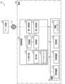
まず、実施の形態に係る制御システムの構成について説明する。図1は、実施の形態に係る制御システムの機能構成を示すブロック図である。 (Embodiment)
[composition]
First, the configuration of a control system according to an embodiment will be described. FIG. 1 is a block diagram showing the functional configuration of a control system according to an embodiment.
図1に示されるように、制御システム10は、制御装置20と、複数の機器30と、サーバ装置50とを備える。 As shown in FIG. 1, the
図1に示される建物80は、例えば、集合住宅または戸建住宅などの住宅である。建物80内には、制御装置20及び機器30が設置されている。サーバ装置50は、クラウド(言い換えれば、クラウドサーバ)として実現される。 The
まず、制御装置20について説明する。制御装置20は、例えば、エネルギーマネジメント機能を有するHEMSコントローラであり、建物80内に設置され、建物80内に設置された機器30の消費電力を管理する。また、制御装置20は、機器30の状態の取得及び表示、並びに、建物80内(あるいは、建物80の敷地内)に設置された機器30の制御などを行う。制御装置20は、HEMSコントローラに限定されず、エネルギーマネジメント機能を有しない他のホームコントローラ、または、ゲートウェイ装置であってもよい。 First, the
なお、機器30は、例えば、照明機器31及び空調機器32などの家電機器であり、機器30の状態とは、例えば、機器30の動作状態、及び、機器30の消費電力の状態を意味する。動作状態には、具体的には、電源オン状態、電源オフ状態、及び、設定状態(機器30が空調機器であれば設定温度、機器30が照明機器であれば明るさなど)などが含まれる。 Note that the
制御装置20は、具体的には、表示部22と、マイクロフォン23と、制御部24と、記憶部25と、第一通信部26と、第二通信部27とを備える。表示部22、及び、マイクロフォン23は、入力受付部21を構成する。 Specifically, the
表示部22は、画像の表示機能、及び、ユーザの手動入力を受け付ける機能を有する表示デバイスである。表示部22は、タッチパネル、及び、液晶パネルまたは有機EL(Electro Luminescence)パネルなどの表示パネルによって実現される。タッチパネルは、例えば、静電容量方式のタッチパネルであるが、抵抗膜方式のタッチパネルであってもよい。 The
マイクロフォン23は、ユーザの音声入力を受け付ける。マイクロフォン23は、音声取得部の一例である。 The
制御部24は、表示部22への画像の表示制御、及び、マイクロフォン23へ入力された音声の音声認識処理などを行う。制御部24は、例えば、マイクロコンピュータによって実現されるが、プロセッサによって実現されてもよい。 The
記憶部25は、制御部24が実行する制御プログラムなどが記憶される記憶装置である。記憶部25は、例えば、半導体メモリなどによって実現される。 The
第一通信部26は、制御装置20がサーバ装置50とインターネットなどの広域通信ネットワーク70を介して通信を行うための通信モジュール(通信回路)である。第一通信部26によって行われる通信は、例えば、無線通信であるが、有線通信であってもよい。通信に用いられる通信規格についても特に限定されない。 The
第二通信部27は、制御装置20が、機器30と局所通信ネットワークを介して通信を行うための通信モジュール(通信回路)である。第二通信部27によって行われる通信は、例えば、無線通信であるが、有線通信であってもよい。通信に用いられる通信規格についても、特に限定されない。なお、第二通信部27と機器30との間の通信は、例えば、ECHONET Lite(登録商標)に準拠する。 The
次に、機器30について説明する。機器30は、制御装置20の制御対象の機器である。機器30は、例えば、制御装置20と通信を行うための通信モジュール(通信回路)を備え、制御装置20から受信した制御信号にしたがって動作する。機器30には、例えば、照明機器31、空調機器32、電気錠33、及び、電動シャッター34などが含まれる。 Next, the
機器30には、これ以外の機器が含まれてもよい。例えば、機器30には、建物80における消費電力を計測する分電盤またはスマートメータなどの機器が含まれてもよく、このような機器によって計測された消費電力は、記憶部25に消費電力の履歴情報として記憶される。 The
照明機器31は、建物80の中(室内)を照明する。照明機器31は、例えば、シーリングライトであるが、照明機器31の具体的態様は、特に限定されない。照明機器31は、ダウンライト、ペンダントライト、スポットライト、または、ブラケットライトなどであってもよい。また、照明機器31は、建物80の外(室外)を照明する機器であってもよい。 The
空調機器32は、一般家庭用の空調機器である。空調機器32は、熱交換器(図示せず)などを有することにより、空調機器32から送出される風の温度の調整が可能な空調機器である。つまり、空調機器32は、温度調整機能(送風機能及び冷暖房機能)を有する。空調機器32は、一般家庭用の空調機器に限定されず、産業用の空調機器であってもよい。 The
電気錠33は、建物80が有するドア(または窓など)の開錠及び施錠を制御する防犯機器である。電気錠33は、例えば、カードキーなどから鍵情報を取得するRFIDリーダを備える。また、電気錠33は、指紋などの生体情報を鍵情報として取得する生体センサを備えてもよい。以下の実施の形態では、電気錠33は、玄関のドアに設けられた電気錠であるものとして説明される。 The
電動シャッター34は、建物80が有する窓の外側(または内側)に配置され、建物80内への外光の取り入れ量を調整する。電動シャッター34は、例えば、電動ブラインドなどであり、物理的に光の遮蔽物が開閉する構成を有する。電動シャッター34は、液晶パネルなどを備え、物性的に光の透過率が変化する構成であってもよい。 The
[シーン制御]
次に、制御装置20によって行われるシーン制御について説明する。シーン制御は、建物80内を所定の室内環境に近づけるために、建物80内に配置された2以上の機器30を一括して動作させる制御である。図2は、シーン制御を実行するための制御情報の一例を示す図である。 [Scene control]
Next, scene control performed by the
シーン制御の制御情報においては、起床、外出、及び、就寝などの生活シーン(シーン名称)のそれぞれに対して、機器30の制御内容が紐づけられている。例えば、ユーザは、表示部22に対して「起床」のシーン制御の実行を指示する操作(以下、実行入力とも記載される)を行うと、制御装置20は、図2の制御情報を参照して機器30を制御し、この結果、照明機器31及び空調機器32があらかじめ登録された設定(明るさ、設定温度など)でオンし、電動シャッター34が開く。「起床」のシーン制御の実行が指示されたときに、どのような機器30がどのような動作を行うかは、ユーザがあらかじめ登録することができる。 In the scene control control information, the control details of the
[動作例1]
制御システム10は、複数の機器30に含まれる1つの機器30の状態の変化を契機に、機器30の状態変化から推定される生活シーンに関連付けられたシーン制御の実行画面を表示することができる。制御システム10は、例えば、電気錠33が解錠状態になったことを契機に、これをユーザの帰宅であると推定して、「帰宅」のシーン制御の実行画面を表示する。以下、このような制御システム10の動作例1について説明する。図3は、制御システム10の動作例1のシーケンス図である。 [Operation example 1]
The
制御装置20の制御部24は、表示部22によってユーザの「外出」のシーン制御の実行入力が受け付けられると(S11)、「外出」のシーン制御を実行する(S12)。制御部24は、具体的には、記憶部25にあらかじめ記憶されたシーン制御の制御情報(図2)を参照し、第二通信部27に、「外出」のシーン制御において制御対象となる機器へ制御信号を送信させる。図2の例では、制御対象となる機器は、照明機器31、空調機器32、及び、電動シャッター34である。「外出」のシーン制御が実行されると、照明機器31及び空調機器32はオフし、電動シャッター34は閉じる。 The
その後、第二通信部27によって電気錠33から電気錠33の状態を示す状態情報が取得されると(S13)、制御部24は、取得された状態情報が、電気錠33が施錠状態から解錠状態に変化したことを示すか否かを判定する(S14)。状態情報は、所定の情報の一例である。所定の情報は、トリガとして使用できる情報であればよく、状態情報以外の情報であってもよい。 After that, when the
取得された状態情報が、電気錠33が施錠状態から解錠状態に変化したことを示さないと判定された場合(S14でNo)、状態情報の取得が再度行われる(S13)。一方、制御部24は、状態情報が、電気錠33が施錠状態から解錠状態に変化したことを示すと判定すると(S14でYes)、現在時刻(状態情報が取得された時刻)が猶予期間の経過後の時刻であるか否かを判定する(S15)。猶予期間は、ユーザが「外出」のシーン制御の実行入力を行った時刻を開始時刻とする期間である。猶予期間は、例えば、30分程度の期間であるが、特に限定されない。猶予期間の長さは、表示部22へのユーザの入力に基づいて設定されてもよい。 If it is determined that the acquired state information does not indicate that the
現在時刻が猶予期間内であると判定された場合(S15でNo)の電気錠33の解錠は、ユーザが建物80の外へ出るために行ったものである可能性がある。つまり、このような場合に、「帰宅」のシーン制御の実行画面が表示されることは適切でない。したがって、この場合、「帰宅」のシーン制御の実行画面は表示されず、状態情報の取得が再度行われる(S13)。 When it is determined that the current time is within the grace period (No in S15), there is a possibility that the user unlocks the
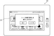
これに対し、現在時刻が猶予期間の経過後であると判定された場合(S15でYes)の電気錠33の解錠は、ユーザが実際に帰宅した際に行ったものであると考えられる。そこで、制御部24は、現在時刻が猶予期間の経過後の時刻であると判定すると(S15でYes)、表示部22に「帰宅」のシーン制御の実行画面を表示させる(S16)。図4は、「帰宅」のシーン制御の実行画面の一例を示す図である。 On the other hand, when it is determined that the current time is after the grace period has elapsed (Yes in S15), it is considered that the
図4に示されるように、「帰宅」のシーン制御の実行画面(以下、単に実行画面とも記載される)は、「帰宅」のシーン制御を実行するためのオブジェクト(例えば、図4の「はい」のボタン)を含む。なお、実行画面が表示されている状態は、言い換えれば、シーン制御を実行するための実行入力を受け付け可能な準備状態である。 As shown in Figure 4, the scene control execution screen for "Going home" (hereinafter also simply referred to as the execution screen) is an object for executing scene control for "Going home" (for example, "Yes" in Figure 4). button). In other words, the state in which the execution screen is displayed is a preparation state in which execution input for executing scene control can be accepted.
制御部24は、表示部22がスリープ状態であり、待機画面(例えば、黒画など)を表示している場合には、表示部22を起動し、起動後の表示部22に実行画面を表示させる。つまり、表示部22は、待機画面を実行画面に切り替える。また、制御部24は、表示部22が待機画面以外の他の画面を表示している場合には、当該他の画面に代えて実行画面を表示させる(つまり、画面を遷移させる)が、当該他の画面に実行画面を重畳表示(言い換えれば、ポップアップ表示)させてもよい。図5は、他の画面に重畳表示される、実行画面の一例を示す図である。他の画面は、例えば、機器30を制御するための制御画面などである。 When the
実行画面が表示されている間、制御部24は、表示部22によって「帰宅」のシーン制御の実行入力(例えば、図4及び図5の「はい」のボタンへのタップ操作)が受け付けられたか否かを判定する(S17)。制御部24は、「帰宅」のシーン制御の実行入力が受け付けられたと判定すると(S17でYes)、「帰宅」のシーン制御を実行する(S18)。制御部24は、具体的には、記憶部25にあらかじめ記憶されたシーン制御の制御情報(図2)を参照し、第二通信部27に、「帰宅」のシーン制御において制御対象となる機器へ制御信号を送信させる。図2の例では、制御対象となる機器は、照明機器31、空調機器32、及び、電動シャッター34である。「帰宅」のシーン制御が実行されると、照明機器31及び空調機器32はオンし、電動シャッター34は開く。 While the execution screen is being displayed, the
制御部24は、「帰宅」のシーン制御の実行入力が受け付けられていないと判定すると(S17でNo)、実行画面の表示が開始されてから所定期間が経過したか否かを判定する(S19)。所定期間は、例えば、30分程度の期間であるが、特に限定されない。所定期間の長さは、表示部22へのユーザの入力に基づいて設定されてもよい。 If the
制御部24は、実行画面の表示が開始されてから所定期間が経過していないと判定した場合には(S19でNo)、表示部22に実行画面の表示を継続させる(S16)。一方、制御部24は、所定期間が経過したと判定した場合には(S19でYes)、ユーザが「帰宅」のシーン制御を実行する意思がないものとみなして、表示部22に、実行画面の表示を解除させる(S20)。この場合、表示部22は、例えば、実行画面を表示する前の画面(待機画面または他の画面)を表示する。 If the
以上説明したように、制御システム10は、第二通信部27によって電気錠33から所定の情報(具体的には、電気錠33が解錠状態に変化したことを示す状態情報)が取得されたことを契機に、入力受付部21を、シーン制御を実行するための実行入力を受け付け可能な準備状態にする。制御システム10は、具体的には、シーン制御を実行するためのオブジェクトを含む実行画面を表示部22に表示させることで、入力受付部21を準備状態にする。実行画面は、ユーザがワンタッチでシーン制御を実行することができる画面であり、電気錠33が開錠された後、ユーザが表示部22へ何らかの入力(操作)を行う前に表示される。これにより、ユーザはシーン制御を速やかに実行することができる。 As explained above, in the
[動作例2]
動作例1では、制御システム10は、「帰宅」のシーン制御と別の「外出」のシーン制御が実行され、かつ、その後に電気錠33から所定の情報が取得されたことを要件として、「帰宅」のシーン制御を実行するための実行画面を表示部22に表示させた。しかしながら、このような構成は必須ではない。例えば、制御システム10は、所定の時間帯に機器30から所定の情報が取得されたことを要件として、実行画面を表示部22に表示させてもよい。以下、このような制御システム10の動作例2について説明する。図6は、制御システム10の動作例2のフローチャートである。 [Operation example 2]
In operation example 1, the
制御装置20の制御部24は、第二通信部27によって空調機器32から空調機器32の状態を示す状態情報が取得されると(S21)、取得された状態情報が、空調機器32がオン状態からオフ状態に変化したことを示すか否かを判定する(S22)。 When the
取得された状態情報が、空調機器32がオン状態からオフ状態に変化したことを示さないと判定された場合(S22でNo)、状態情報の取得が再度行われる(S21)。一方、制御部24は、状態情報が、空調機器32がオン状態からオフ状態に変化したことを示すと判定すると(S22でYes)、現在時刻(状態情報が取得された時刻)が所定の時間帯に属するか否かを判定する(S23)。動作例2では、所定の時間帯は、ユーザが外出する可能性が高い時間帯であり、例えば、8:00~20:00までの時間帯などである。所定の時間帯は、表示部22へのユーザの入力に基づいて設定されてもよい。 If it is determined that the acquired state information does not indicate that the
現在時刻が所定の時間帯に属さないと判定された場合(S23でNo)の空調機器32のオフは、ユーザが建物80から外出するために行ったものではないと考えられる。したがって、この場合、「外出」のシーン制御の実行画面は表示されず、状態情報の取得が再度行われる(S21)。 When it is determined that the current time does not belong to the predetermined time zone (No in S23), it is considered that the user did not turn off the
これに対し、現在時刻が所定の時間帯に属すると判定された場合(S23でYes)の空調機器32のオフは、ユーザが建物80から外出するために行ったものであると考えられる。そこで、制御部24は、現在時刻が所定の時間帯に属すると判定すると(S23でYes)、表示部22に「外出」のシーン制御の実行画面を表示させる(S24)。ステップS24の処理は、シーン制御の内容が異なる点を除いて、動作例1のステップS16と同様である。 On the other hand, when it is determined that the current time belongs to the predetermined time zone (Yes in S23), it is considered that the user turned off the
実行画面が表示されている間、制御部24は、表示部22によって「外出」のシーン制御の実行入力が受け付けられたか否かを判定する(S25)。制御部24は、「外出」のシーン制御の実行入力が受け付けられたと判定すると(S25でYes)、「外出」のシーン制御を実行する(S26)。ステップS26の処理は、シーン制御の内容が異なる点を除いて、動作例1のステップS18と同様である。 While the execution screen is being displayed, the
制御部24は、「外出」のシーン制御の実行入力が受け付けられていないと判定すると(S25でNo)、実行画面の表示が開始されてから所定期間が経過したか否かを判定する(S27)。所定期間は、例えば、30分程度の期間であるが、特に限定されない。所定期間の長さは、表示部22へのユーザの入力に基づいて設定されてもよい。 When the
制御部24は、実行画面の表示が開始されてから所定期間が経過していないと判定した場合には(S27でNo)、表示部22に実行画面の表示を継続させる(S24)。一方、制御部24は、所定期間が経過したと判定した場合には(S27でYes)、ユーザが「外出」のシーン制御を実行する意思がないものとみなして、表示部22に、実行画面の表示を解除させる(S28)。この場合、表示部22は、例えば、実行画面を表示する前の画面(待機画面または他の画面)を表示する。 If the
以上説明したように、動作例2では、制御システム10は、所定の時間帯に、第二通信部27によって空調機器32から所定の情報(具体的には、空調機器32がオフ状態に変化したことを示す状態情報)が取得されたことを契機に、入力受付部21を、シーン制御を実行するための実行入力を受け付け可能な準備状態にする。これにより、ユーザはシーン制御を速やかに実行することができる。 As described above, in operation example 2, the
[変形例1]
動作例1及び動作例2では、シーン制御は、実行画面に含まれるオブジェクトへの手動入力によって実行されたが、シーン制御は、音声入力によって実行されてもよい。 [Modification 1]
In operation example 1 and operation example 2, scene control was executed by manual input to objects included in the execution screen, but scene control may also be executed by voice input.
この場合、動作例1のステップS14(または動作例2のステップS24)において、制御部24は、マイクロフォン23を起動し、かつ、表示部22に音声入力画面を表示させる。つまり、制御部24は、第二通信部27によって電気錠33から所定の情報(具体的には、電気錠33が解錠状態に変化したことを示す状態情報)が取得されたことを契機に、マイクロフォン23を起動し、かつ、表示部22に音声入力画面を表示させる。図7は、音声入力画面の一例を示す図である。 In this case, in step S14 of operation example 1 (or step S24 of operation example 2),
マイクロフォン23を起動するとは、マイクロフォン23の電源をオンし、マイクロフォン23を、音声を取得可能な状態にすることである。このとき、制御部24は、マイクロフォン23を通じて入力される音声の音声認識が可能なスタンバイ状態となる。制御部24が音声認識処理を行うことが可能な状態は、言い換えれば、シーン制御を実行するための実行入力を受け付け可能な準備状態である。 Activating the
以上説明したように、制御システム10は、第二通信部27によって電気錠33から所定の情報(具体的には、電気錠33が解錠状態に変化したことを示す状態情報)が取得されたことを契機に、マイクロフォン23を起動することで入力受付部21を準備状態にしてもよい。 As explained above, in the
[変形例2]
また、上記実施の形態で制御装置20が実行する処理の一部または全部は、サーバ装置50によって実行されてもよい。例えば、制御装置20は、主としてユーザインタフェース装置として機能し、シーン制御に関する実質的な情報処理はサーバ装置50によって行われてもよい。 [Modification 2]
Further, part or all of the processing executed by the
[効果等]
以上説明したように、制御システム10は、ユーザの入力を受け付ける入力受付部21と、複数の機器30と通信する第二通信部27と、第二通信部27によって複数の機器30に含まれる1つの機器から所定の情報が取得されたことを契機に、入力受付部21を、複数の機器30の少なくとも一部を制御対象とするシーン制御であって生活シーンに関連付けられたシーン制御を実行するための実行入力を受け付け可能な準備状態にする制御部24とを備える。上記1つの機器は、動作例1では電気錠33であり、動作例2では空調機器32であるが、特に限定されない。 [Effects etc.]
As described above, the
このような制御システム10は、シーン制御が実行されるまでの手順を簡略化することができる。制御システム10によれば、ユーザは入力受付部21を準備状態にするための入力などを行う必要がないため、実行入力を速やかに行うことができる。つまり、制御システム10は、実行入力を速やかに行うことを支援することができる。また、このような制御システム10は、ユーザが自身の手動入力等により入力受付部21を解除準備状態にするときに生じる処理(表示部22による手動入力の検出など)が省略できる。つまり、制御システム10は、情報処理量を低減することができる。 Such a
また、例えば、入力受付部21は、画像の表示機能及びユーザの手動入力を受け付ける機能を有する表示部22を含む。制御部24は、シーン制御を実行するためのオブジェクトを表示部22に表示させることで、入力受付部21を準備状態にする。 Further, for example, the
このような制御システム10は、シーン制御を実行するためのオブジェクトを表示することで、シーン制御が実行されるまでの手順を簡略化することができる。 Such a
また、例えば、表示部22は、第二通信部27によって上記1つの機器から所定の情報が取得されてから所定期間の間、オブジェクトを表示する。 Further, for example, the
このような制御システム10は、所定期間の経過後にオブジェクトの表示を解除することで、不要なオブジェクトの表示が継続されることを抑制することができる。 Such a
また、例えば、制御部24は、第二通信部27によって上記1つの機器から所定の情報が取得されたことを契機に、スリープ状態の表示部22を起動し、起動後の表示部22にオブジェクトを表示させる。 Further, for example, when the
このような制御システム10は、表示部22がスリープ状態であっても、表示部22を起動してシーン制御を実行するためのオブジェクトを表示することで、シーン制御が実行されるまでの手順を簡略化することができる。 Such a
また、例えば、所定の情報は、上記1つの機器の状態変化を示す情報であり、制御部24は、第二通信部27によって上記1つの機器から所定の情報が取得されたことを契機に、上記1つの機器の状態変化から推定される生活シーンに関連付けられたシーン制御を実行するためのオブジェクトを表示部22に表示させる。 Further, for example, the predetermined information is information indicating a change in the state of the one device, and the
このような制御システム10は、より適切なシーン制御の実行をユーザに提案することができる。 Such a
また、例えば、上記1つの機器は、電気錠33であり、所定の情報は、電気錠33が施錠状態から解錠状態に変化したことを示す情報であり、上記1つの機器の状態変化から推定される生活シーンは、帰宅シーンである。 Further, for example, the above-mentioned one device is an
このような制御システム10は、電気錠33が開錠状態に変化したことを契機に、帰宅シーンに関連付けられたシーン制御の実行をユーザに提案することができる。 Such a
また、例えば、制御部24は、所定の時間帯に第二通信部27によって上記1つの機器から所定の情報が取得されたことを契機に、シーン制御を実行するためのオブジェクトを表示部22に表示させる。 Further, for example, when the
このような制御システム10は、所定の情報が取得された時刻が所定の時間帯に属するか否かを考慮して、シーン制御を実行するためのオブジェクトを表示することができる。 Such a
また、例えば、制御部24は、上記シーン制御と別のシーン制御が実行された後に上記1つの機器から所定の情報が取得されたことを契機に、上記シーン制御を実行するためのオブジェクトを表示部22に表示させる。 Further, for example, the
このような制御システム10は、所定の情報が取得される前に別のシーン制御が行われたか否かを考慮して、シーン制御を実行するためのオブジェクトを表示することができる。 Such a
また、例えば、上記シーン制御は、帰宅シーンに関連付けられたシーン制御であり、別のシーン制御は、外出シーンに関連付けられたシーン制御である。 Further, for example, the above scene control is a scene control associated with a returning home scene, and another scene control is a scene control associated with an outing scene.
このような制御システム10は、所定の情報が取得される前に外出シーンに関連付けられたシーン制御が行われたか否かを考慮して、帰宅シーンに関連付けられたシーン制御を実行するためのオブジェクトを表示することができる。 Such a
また、例えば、制御部24は、表示部22により、表示部22が表示しているオブジェクトへのユーザの手動入力が受け付けられると、シーン制御を実行する。 For example, the
このような制御システム10は、表示部22が表示しているオブジェクトへのユーザの手動入力に応じてシーン制御を実行することができる。 Such a
また、例えば、入力受付部21は、ユーザの音声入力を実行入力として受け付けるマイクロフォン23を含み、制御部24は、マイクロフォン23を起動することで、入力受付部21を準備状態にする。 Further, for example, the
このような制御システム10は、シーン制御を実行するための音声入力を受け付けるマイクロフォンを起動することで、シーン制御が実行されるまでの手順を簡略化することができる。 Such a
また、制御システム10などのコンピュータによって実行される制御方法は、複数の機器30と通信する通信ステップと、通信によって複数の機器30に含まれる1つの機器から所定の情報が取得されたことを契機に、ユーザの入力を受け付ける入力受付部21を、複数の機器30の少なくとも一部を制御対象とするシーン制御であって生活シーンに関連付けられたシーン制御を実行するための実行入力を受け付け可能な準備状態にする制御ステップとを含む。 Further, the control method executed by a computer such as the
このような制御方法は、シーン制御が実行されるまでの手順を簡略化することができる。 Such a control method can simplify the procedure until scene control is executed.
(その他の実施の形態)
以上、実施の形態について説明したが、本発明は、上記実施の形態に限定されるものではない。 (Other embodiments)
Although the embodiments have been described above, the present invention is not limited to the above embodiments.
例えば、上記実施の形態では、ユーザは、シーン制御の実行画面が表示された状態において1回の操作でシーン制御を実行することが可能である。しかしながら、実行画面が表示された状態において、シーン制御を実行するために2回以上の操作が行われてもよい。実行画面が表示された状態においては、多くとも2回程度の操作でシーン制御が実行されるとよい。 For example, in the above embodiment, the user can execute scene control with a single operation while the scene control execution screen is displayed. However, in a state where the execution screen is displayed, an operation may be performed two or more times to execute scene control. In a state where the execution screen is displayed, scene control is preferably executed by performing the operation twice at most.
また、上記実施の形態では、制御システムは、複数の装置によって実現されたが、単一の装置として実現されてもよい。例えば、制御システムは、制御装置に相当する単一の装置として実現されてもよいし、制御装置と同様の処理を行う携帯端末に相当する単一の装置として実現されてもよい。制御システムが複数の装置によって実現される場合、制御システムが備える構成要素は、複数の装置にどのように振り分けられてもよい。 Further, in the above embodiments, the control system is realized by a plurality of devices, but it may be realized as a single device. For example, the control system may be realized as a single device corresponding to a control device, or may be realized as a single device corresponding to a mobile terminal that performs the same processing as the control device. When the control system is realized by a plurality of devices, the components included in the control system may be distributed to the plurality of devices in any manner.
例えば、上記実施の形態における装置間の通信方法については特に限定されるものではない。また、装置間の通信においては、図示されない中継装置が介在してもよい。 For example, the communication method between devices in the above embodiment is not particularly limited. Further, in communication between devices, a relay device (not shown) may intervene.
また、上記実施の形態において、特定の処理部が実行する処理を別の処理部が実行してもよい。また、複数の処理の順序が変更されてもよいし、複数の処理が並行して実行されてもよい。また、上記実施の形態の動作例1、動作例2、変形例1、及び、変形例2は任意に組み合わされてよい。 Further, in the above embodiments, the processing executed by a specific processing unit may be executed by another processing unit. Further, the order of the plurality of processes may be changed, or the plurality of processes may be executed in parallel. Further, operation example 1, operation example 2, modification example 1, and modification example 2 of the above embodiments may be arbitrarily combined.
また、上記実施の形態において、各構成要素は、各構成要素に適したソフトウェアプログラムを実行することによって実現されてもよい。各構成要素は、CPUまたはプロセッサなどのプログラム実行部が、ハードディスクまたは半導体メモリなどの記録媒体に記録されたソフトウェアプログラムを読み出して実行することによって実現されてもよい。 Furthermore, in the embodiments described above, each component may be realized by executing a software program suitable for each component. Each component may be realized by a program execution unit such as a CPU or a processor reading and executing a software program recorded on a recording medium such as a hard disk or a semiconductor memory.
また、各構成要素は、ハードウェアによって実現されてもよい。例えば、各構成要素は、回路(または集積回路)でもよい。これらの回路は、全体として1つの回路を構成してもよいし、それぞれ別々の回路でもよい。また、これらの回路は、それぞれ、汎用的な回路でもよいし、専用の回路でもよい。 Moreover, each component may be realized by hardware. For example, each component may be a circuit (or integrated circuit). These circuits may constitute one circuit as a whole, or may be separate circuits. Further, each of these circuits may be a general-purpose circuit or a dedicated circuit.
また、本発明の全般的または具体的な態様は、システム、装置、方法、集積回路、コンピュータプログラムまたはコンピュータ読み取り可能なCD-ROMなどの記録媒体で実現されてもよい。また、システム、装置、方法、集積回路、コンピュータプログラム及び記録媒体の任意な組み合わせで実現されてもよい。 Further, general or specific aspects of the present invention may be implemented in a system, apparatus, method, integrated circuit, computer program, or computer readable storage medium such as a CD-ROM. Further, the present invention may be realized by any combination of a system, an apparatus, a method, an integrated circuit, a computer program, and a recording medium.
例えば、本発明は、制御システムなどのコンピュータが実行する制御方法として実現されてもよいし、このような制御方法をコンピュータに実行させるためのプログラムとして実現されてもよいし、このようなプログラムが記録されたコンピュータ読み取り可能な非一時的な記録媒体として実現されてもよい。 For example, the present invention may be realized as a control method executed by a computer such as a control system, or may be realized as a program for causing a computer to execute such a control method, or such a program may be implemented as a control method executed by a computer such as a control system. It may also be implemented as a recorded computer-readable non-transitory storage medium.
その他、各実施の形態に対して当業者が思いつく各種変形を施して得られる形態、または、本発明の趣旨を逸脱しない範囲で各実施の形態における構成要素及び機能を任意に組み合わせることで実現される形態も本発明に含まれる。 Other embodiments may be obtained by making various modifications to each embodiment that a person skilled in the art would think of, or may be realized by arbitrarily combining the components and functions of each embodiment without departing from the spirit of the present invention. The present invention also includes such forms.
10 制御システム
21 入力受付部
22 表示部
23 マイクロフォン
24 制御部
27 第二通信部(通信部)
30 機器
31 照明機器
32 空調機器
33 電気錠
34 電動シャッター
50 サーバ装置
70 広域通信ネットワーク
80 建物 10
30
Claims (11)
Translated fromJapanese複数の機器と通信する通信部と、
前記通信部によって前記複数の機器に含まれる電気錠から前記電気錠が施錠状態から解錠状態に変化したことを示す所定の情報が取得されたことを契機に、前記複数の機器の少なくとも一部を制御対象とするシーン制御であって帰宅シーンに関連付けられたシーン制御を実行するためのオブジェクトを前記表示部に表示させることにより、前記入力受付部を前記シーン制御の実行入力を受け付け可能な準備状態にする制御部とを備える
制御システム。 an input receptionunit including a display unit that is an input reception unit that receives user input and has an image display function and a function of accepting manual input from the user ;
a communication section that communicates with multiple devices;
When the communication unit acquires predetermined informationindicating that the electric lock has changed from a locked state to an unlocked state from anelectric lock included in the plurality of devices, at least some of the plurality of devices Prepare the input receiving unit to receive an input for executing the scene controlby displaying on the display unit an object for executing scene control that is a control target and is associated with areturning home scene. A control system comprising: a control unit that sets the state;
複数の機器と通信する通信部と、
前記通信部によって前記複数の機器に含まれる1つの機器から所定の情報が取得されたことを契機に、前記複数の機器の少なくとも一部を制御対象とするシーン制御であって生活シーンに関連付けられたシーン制御を実行するためのオブジェクトを前記表示部に表示させることにより、前記入力受付部を前記シーン制御の実行入力を受け付け可能な準備状態にする制御部とを備え、
前記制御部は、前記通信部によって前記1つの機器から前記所定の情報が取得されたことを契機に、スリープ状態の前記表示部を起動し、起動後の前記表示部に前記オブジェクトを表示させる
制御システム。 an input receptionunit including a display unit that is an input reception unit that receives user input and has an image display function and a function of accepting manual input from the user ;
a communication section that communicates with multiple devices;
When predetermined information is acquired from one device included in the plurality of devices by the communication unit, scene control is performed to control at least a part of the plurality of devices and is associated with a life scene. a control unit that causesthe input receiving unit to be in a ready state capable of accepting input for executing the scene control by displaying an object for executing the scene control on the display unit,
The control unit activates the display unit in a sleep state when the communication unit acquires the predetermined information from the one device, and causes the display unit to display the object after activation.
control system.
複数の機器と通信する通信部と、
前記通信部によって前記複数の機器に含まれる1つの機器から所定の情報が取得されたことを契機に、前記複数の機器の少なくとも一部を制御対象とするシーン制御であって生活シーンに関連付けられたシーン制御を実行するためのオブジェクトを前記表示部に表示させることにより、前記入力受付部を前記シーン制御の実行入力を受け付け可能な準備状態にする制御部とを備え、
前記制御部は、前記シーン制御と別のシーン制御が実行された後に前記1つの機器から前記所定の情報が取得されたことを契機に、前記シーン制御を実行するための前記オブジェクトを前記表示部に表示させ、
前記シーン制御は、帰宅シーンに関連付けられたシーン制御であり、
前記別のシーン制御は、外出シーンに関連付けられたシーン制御である
制御システム。 an input receptionunit including a display unit that is an input reception unit that receives user input and has an image display function and a function of accepting manual input from the user ;
a communication section that communicates with multiple devices;
When the communication unit acquires predetermined information from one device included in the plurality of devices, scene control is performed that controls at least some of the plurality of devices and is associated with a life scene.a control unit that displays an object for executing the scene control on the display unit, thereby setting the input receiving unit in a ready state capable of accepting an input for executing the scene control;
The control unit displays the object for executing the scene control on the display unit, triggered by the acquisition of the predetermined information from the one device after the scene control and another scene control are executed. display it on
The scene control is a scene control associated with a returning home scene,
The another scene control is a scene control associated with an outing scene.
control system.
請求項1~3のいずれか1項に記載の制御システム。 The control system according toany one of claims 1 to 3, wherein the control unit causes the display unit to display the object for a predetermined period of time after the communication unit acquiresthe predetermined information.
請求項1~4のいずれか1項に記載の制御システム。 The control unit executes the scene control when the display unit receives manual input from the user to the object displayed bythe display unit. control system.
前記通信によって前記複数の機器に含まれる電気錠から前記電気錠が施錠状態から解錠状態に変化したことを示す所定の情報が取得されたことを契機に、前記複数の機器の少なくとも一部を制御対象とするシーン制御であって帰宅シーンに関連付けられたシーン制御を実行するためのオブジェクトを画像の表示機能及びユーザの手動入力を受け付ける機能を有する表示部に表示することにより、前記ユーザの入力を受け付ける入力受付部であって前記表示部を含む入力受付部を前記シーン制御の実行入力を受け付け可能な準備状態にする制御ステップとを含む
制御方法。 a communication step for communicating with multiple devices;
When predetermined information indicating that theelectric lockhas changed from a locked state to an unlocked state is acquired from an electric lock included in the plurality of devices through the communication, at least some of the plurality of devices By displaying an object for executing scene control that is a control target and that is associated with areturning home sceneon a display unit that has an image display function and a function that accepts manual input from the user, the user's A control method, comprising: a control stepof bringing an input receiving section that receives an input, including the display section, into a ready state capable of receiving an input for executing the scene control .
前記通信によって前記複数の機器に含まれる1つの機器から所定の情報が取得されたことを契機に、前記複数の機器の少なくとも一部を制御対象とするシーン制御であって生活シーンに関連付けられたシーン制御を実行するためのオブジェクトを画像の表示機能及びユーザの手動入力を受け付ける機能を有する表示部に表示することにより、前記ユーザの入力を受け付ける入力受付部であって前記表示部を含む入力受付部を前記シーン制御の実行入力を受け付け可能な準備状態にする制御ステップとを含み、
前記制御ステップにおいては、前記通信によって前記1つの機器から前記所定の情報が取得されたことを契機に、スリープ状態の前記表示部を起動し、起動後の前記表示部に前記オブジェクトを表示する
制御方法。 a communication step for communicating with multiple devices;
In response to the acquisition of predetermined information from one device included in the plurality of devices through the communication, scene control is performed that targets at least some of the plurality of devices and is associated with a life scene.By displaying an object for performing scene control on a display section having an image display function and a function of accepting manual input from a user, an input receiving section that receives input from the user and includes the display section. a control step of placingthe reception unit in a ready state capable of accepting input for executing the scene control;
In the control step, upon acquisition of the predetermined information from the one device through the communication, the display unit in a sleep state is activated, and the object is displayed on the display unit after activation.
Control method.
前記通信によって前記複数の機器に含まれる1つの機器から所定の情報が取得されたことを契機に、前記複数の機器の少なくとも一部を制御対象とするシーン制御であって生活シーンに関連付けられたシーン制御を実行するためのオブジェクトを画像の表示機能及びユーザの手動入力を受け付ける機能を有する表示部に表示することにより、前記ユーザの入力を受け付ける入力受付部であって前記表示部を含む入力受付部を前記シーン制御の実行入力を受け付け可能な準備状態にする制御ステップとを含み、
前記制御ステップにおいては、前記シーン制御と別のシーン制御が実行された後に前記1つの機器から前記所定の情報が取得されたことを契機に、前記シーン制御を実行するための前記オブジェクトを前記表示部に表示し、
前記シーン制御は、帰宅シーンに関連付けられたシーン制御であり、
前記別のシーン制御は、外出シーンに関連付けられたシーン制御である
制御方法。 a communication step for communicating with multiple devices;
In response to the acquisition of predetermined information from one device included in the plurality of devices through the communication, scene control is performed that targets at least some of the plurality of devices and is associated with a life scene. An input reception unit that receives input from the user and includes the display unit by displaying an object for performing scene control on a display unit that has an image display function and a function of accepting manual input from the user. a control step of placing the reception unit in a ready state capable of accepting input for executing the scene control;
In the control step, when the predetermined information is acquired from the one device after the scene control and another scene control are executed, the object for executing the scene control is displayed. section,
The scene control is a scene control associated with a returning home scene,
The another scene control is a scene control associated with an outing scene.
Control method.
請求項6~8のいずれか1項に記載の制御方法。The control method according to any one of claims 6 to 8.
請求項6~9のいずれか1項に記載の制御方法。The control method according to any one of claims 6 to 9.
Priority Applications (4)
| Application Number | Priority Date | Filing Date | Title |
|---|---|---|---|
| JP2019200552AJP7426619B2 (en) | 2019-11-05 | 2019-11-05 | Control system and control method |
| US17/771,746US20220393902A1 (en) | 2019-11-05 | 2020-11-02 | Control system and control method |
| PCT/JP2020/041127WO2021090816A1 (en) | 2019-11-05 | 2020-11-02 | Control system and control method |
| CN202080073139.2ACN114616836A (en) | 2019-11-05 | 2020-11-02 | Control system and control method |
Applications Claiming Priority (1)
| Application Number | Priority Date | Filing Date | Title |
|---|---|---|---|
| JP2019200552AJP7426619B2 (en) | 2019-11-05 | 2019-11-05 | Control system and control method |
Publications (2)
| Publication Number | Publication Date |
|---|---|
| JP2021077930A JP2021077930A (en) | 2021-05-20 |
| JP7426619B2true JP7426619B2 (en) | 2024-02-02 |
Family
ID=75848395
Family Applications (1)
| Application Number | Title | Priority Date | Filing Date |
|---|---|---|---|
| JP2019200552AActiveJP7426619B2 (en) | 2019-11-05 | 2019-11-05 | Control system and control method |
Country Status (4)
| Country | Link |
|---|---|
| US (1) | US20220393902A1 (en) |
| JP (1) | JP7426619B2 (en) |
| CN (1) | CN114616836A (en) |
| WO (1) | WO2021090816A1 (en) |
Families Citing this family (1)
| Publication number | Priority date | Publication date | Assignee | Title |
|---|---|---|---|---|
| CN118355732A (en)* | 2021-12-20 | 2024-07-16 | 松下知识产权经营株式会社 | Control device, lighting system, lighting control method and program |
Citations (3)
| Publication number | Priority date | Publication date | Assignee | Title |
|---|---|---|---|---|
| JP2002094657A (en) | 2000-09-20 | 2002-03-29 | Sony Corp | Portable communication terminal |
| JP2014045258A (en) | 2012-08-24 | 2014-03-13 | Toshiba Corp | Remote control device |
| JP2018181270A (en) | 2017-04-21 | 2018-11-15 | パナソニックIpマネジメント株式会社 | Display method, program and display system |
Family Cites Families (19)
| Publication number | Priority date | Publication date | Assignee | Title |
|---|---|---|---|---|
| JP3617952B2 (en)* | 2000-09-14 | 2005-02-09 | Kddi株式会社 | Data transfer method and system in mobile IP |
| US10444964B2 (en)* | 2007-06-12 | 2019-10-15 | Icontrol Networks, Inc. | Control system user interface |
| US20100081375A1 (en)* | 2008-09-30 | 2010-04-01 | Apple Inc. | System and method for simplified control of electronic devices |
| US10332059B2 (en)* | 2013-03-14 | 2019-06-25 | Google Llc | Security scoring in a smart-sensored home |
| US9208676B2 (en)* | 2013-03-14 | 2015-12-08 | Google Inc. | Devices, methods, and associated information processing for security in a smart-sensored home |
| US9600645B2 (en)* | 2012-09-21 | 2017-03-21 | Google Inc. | Smart invitation handling at a smart-home |
| US20150350611A1 (en)* | 2013-05-30 | 2015-12-03 | Manything Systems Limited | Methods and systems for monitoring environments using smart devices |
| KR102089459B1 (en)* | 2013-08-16 | 2020-03-16 | 삼성전자 주식회사 | Data communication method and apparatus using a wireless communication |
| US20160189527A1 (en)* | 2014-12-30 | 2016-06-30 | Google Inc. | Intelligent Object-Based Alarm System |
| US9692380B2 (en)* | 2015-04-08 | 2017-06-27 | Google Inc. | Dynamic volume adjustment |
| US20160321946A1 (en)* | 2015-04-29 | 2016-11-03 | Habit Design, Inc, | Facilitating habit formation through use of mobile devices |
| JP6503957B2 (en)* | 2015-07-21 | 2019-04-24 | 富士通コネクテッドテクノロジーズ株式会社 | Electronic device and display control program |
| US10726494B1 (en)* | 2016-01-14 | 2020-07-28 | State Farm Mutual Automobile Insurance Company | Identifying property usage type based upon smart sensor data |
| KR102392113B1 (en)* | 2016-01-20 | 2022-04-29 | 삼성전자주식회사 | Electronic device and method for processing voice command thereof |
| US10264030B2 (en)* | 2016-02-22 | 2019-04-16 | Sonos, Inc. | Networked microphone device control |
| KR20180085931A (en)* | 2017-01-20 | 2018-07-30 | 삼성전자주식회사 | Voice input processing method and electronic device supporting the same |
| US11361060B1 (en)* | 2017-01-23 | 2022-06-14 | Vivint, Inc. | Home automation system supporting dual-authentication |
| CN108536022A (en)* | 2017-03-01 | 2018-09-14 | 武汉海蜘蛛网络科技有限公司 | A kind of home intelligent scene control system |
| JP2019049894A (en)* | 2017-09-11 | 2019-03-28 | エヌ・ティ・ティ・コムウェア株式会社 | Control device, apparatus control system, apparatus control method, and program |
- 2019
- 2019-11-05JPJP2019200552Apatent/JP7426619B2/enactiveActive
- 2020
- 2020-11-02USUS17/771,746patent/US20220393902A1/ennot_activeAbandoned
- 2020-11-02WOPCT/JP2020/041127patent/WO2021090816A1/ennot_activeCeased
- 2020-11-02CNCN202080073139.2Apatent/CN114616836A/enactivePending
Patent Citations (3)
| Publication number | Priority date | Publication date | Assignee | Title |
|---|---|---|---|---|
| JP2002094657A (en) | 2000-09-20 | 2002-03-29 | Sony Corp | Portable communication terminal |
| JP2014045258A (en) | 2012-08-24 | 2014-03-13 | Toshiba Corp | Remote control device |
| JP2018181270A (en) | 2017-04-21 | 2018-11-15 | パナソニックIpマネジメント株式会社 | Display method, program and display system |
Also Published As
| Publication number | Publication date |
|---|---|
| US20220393902A1 (en) | 2022-12-08 |
| WO2021090816A1 (en) | 2021-05-14 |
| JP2021077930A (en) | 2021-05-20 |
| CN114616836A (en) | 2022-06-10 |
Similar Documents
| Publication | Publication Date | Title |
|---|---|---|
| US10140846B2 (en) | Security system re-arming | |
| CN105869252B (en) | A kind of full-automatic numerical control access control system | |
| US20060161270A1 (en) | Distributed wireless home and commercial electrical automation systems | |
| WO2019062335A1 (en) | Information display method and device for intelligent panel | |
| EP2698774B1 (en) | A method and a device for controlling a security system | |
| EP2784611A2 (en) | Electrical equipment control apparatus and electrical equipment control system | |
| TWM558836U (en) | Door lock | |
| JP2007201687A (en) | Equipment control system | |
| JP7426619B2 (en) | Control system and control method | |
| EP1814260A2 (en) | Distributed wireless home network and commercial electrical automation system | |
| JP2018056730A (en) | Apparatus management system, apparatus management method and program | |
| JP7486158B2 (en) | Information processing system and information processing method | |
| CN110347125A (en) | A kind of lighting system of software definition | |
| CN114724277B (en) | Screen-off control method and system, intelligent refrigerator and computer-readable storage medium | |
| JP7523043B2 (en) | Control system and control method | |
| JP7649973B2 (en) | Control system and control method | |
| Roy et al. | IoT based low-cost smart home automation and security system using wireless technology | |
| Hagera et al. | Implementation of smart home automation with enhanced security | |
| US20220385496A1 (en) | Control system and control method | |
| More et al. | Energy Efficient Smart Home Automation | |
| JP7457475B2 (en) | Electrical equipment and equipment control systems | |
| JP7486090B2 (en) | Control system and control method | |
| JP7426580B2 (en) | Control system and control method | |
| Ahmed et al. | Controlling and securing a digital home using multiple sensor based perception system integrated with mobile and voice technology | |
| JP2022079997A (en) | Information processing system and information processing method |
Legal Events
| Date | Code | Title | Description |
|---|---|---|---|
| A621 | Written request for application examination | Free format text:JAPANESE INTERMEDIATE CODE: A621 Effective date:20220712 | |
| A131 | Notification of reasons for refusal | Free format text:JAPANESE INTERMEDIATE CODE: A131 Effective date:20230627 | |
| A601 | Written request for extension of time | Free format text:JAPANESE INTERMEDIATE CODE: A601 Effective date:20230814 | |
| A521 | Request for written amendment filed | Free format text:JAPANESE INTERMEDIATE CODE: A523 Effective date:20231020 | |
| TRDD | Decision of grant or rejection written | ||
| A01 | Written decision to grant a patent or to grant a registration (utility model) | Free format text:JAPANESE INTERMEDIATE CODE: A01 Effective date:20231226 | |
| A61 | First payment of annual fees (during grant procedure) | Free format text:JAPANESE INTERMEDIATE CODE: A61 Effective date:20240112 | |
| R151 | Written notification of patent or utility model registration | Ref document number:7426619 Country of ref document:JP Free format text:JAPANESE INTERMEDIATE CODE: R151 |