JP7424144B2 - Vehicle display device and vehicle display method - Google Patents
Vehicle display device and vehicle display methodDownload PDFInfo
- Publication number
- JP7424144B2 JP7424144B2JP2020050365AJP2020050365AJP7424144B2JP 7424144 B2JP7424144 B2JP 7424144B2JP 2020050365 AJP2020050365 AJP 2020050365AJP 2020050365 AJP2020050365 AJP 2020050365AJP 7424144 B2JP7424144 B2JP 7424144B2
- Authority
- JP
- Japan
- Prior art keywords
- image
- vehicle
- passage
- area
- rear side
- Prior art date
- Legal status (The legal status is an assumption and is not a legal conclusion. Google has not performed a legal analysis and makes no representation as to the accuracy of the status listed.)
- Active
Links
- 238000000034methodMethods0.000titleclaimsdescription28
- 230000002093peripheral effectEffects0.000claimsdescription78
- 230000008569processEffects0.000description17
- 238000012790confirmationMethods0.000description12
- 238000012986modificationMethods0.000description9
- 230000004048modificationEffects0.000description9
- 238000003384imaging methodMethods0.000description8
- 238000010586diagramMethods0.000description7
- 238000012545processingMethods0.000description6
- 238000004590computer programMethods0.000description4
- 238000013459approachMethods0.000description3
- 230000006870functionEffects0.000description3
- 238000010191image analysisMethods0.000description3
- 238000005259measurementMethods0.000description2
- 230000009466transformationEffects0.000description2
- 240000004050Pentaglottis sempervirensSpecies0.000description1
- 235000004522Pentaglottis sempervirensNutrition0.000description1
- 238000004364calculation methodMethods0.000description1
- 238000005516engineering processMethods0.000description1
- 238000002474experimental methodMethods0.000description1
- 230000037361pathwayEffects0.000description1
Images


Classifications
- H—ELECTRICITY
- H04—ELECTRIC COMMUNICATION TECHNIQUE
- H04N—PICTORIAL COMMUNICATION, e.g. TELEVISION
- H04N7/00—Television systems
- H04N7/18—Closed-circuit television [CCTV] systems, i.e. systems in which the video signal is not broadcast
- B—PERFORMING OPERATIONS; TRANSPORTING
- B60—VEHICLES IN GENERAL
- B60R—VEHICLES, VEHICLE FITTINGS, OR VEHICLE PARTS, NOT OTHERWISE PROVIDED FOR
- B60R1/00—Optical viewing arrangements; Real-time viewing arrangements for drivers or passengers using optical image capturing systems, e.g. cameras or video systems specially adapted for use in or on vehicles
- B60R1/20—Real-time viewing arrangements for drivers or passengers using optical image capturing systems, e.g. cameras or video systems specially adapted for use in or on vehicles
- B60R1/22—Real-time viewing arrangements for drivers or passengers using optical image capturing systems, e.g. cameras or video systems specially adapted for use in or on vehicles for viewing an area outside the vehicle, e.g. the exterior of the vehicle
- B60R1/23—Real-time viewing arrangements for drivers or passengers using optical image capturing systems, e.g. cameras or video systems specially adapted for use in or on vehicles for viewing an area outside the vehicle, e.g. the exterior of the vehicle with a predetermined field of view
- B60R1/26—Real-time viewing arrangements for drivers or passengers using optical image capturing systems, e.g. cameras or video systems specially adapted for use in or on vehicles for viewing an area outside the vehicle, e.g. the exterior of the vehicle with a predetermined field of view to the rear of the vehicle
- B—PERFORMING OPERATIONS; TRANSPORTING
- B60—VEHICLES IN GENERAL
- B60R—VEHICLES, VEHICLE FITTINGS, OR VEHICLE PARTS, NOT OTHERWISE PROVIDED FOR
- B60R1/00—Optical viewing arrangements; Real-time viewing arrangements for drivers or passengers using optical image capturing systems, e.g. cameras or video systems specially adapted for use in or on vehicles
- B60R1/20—Real-time viewing arrangements for drivers or passengers using optical image capturing systems, e.g. cameras or video systems specially adapted for use in or on vehicles
- B60R1/22—Real-time viewing arrangements for drivers or passengers using optical image capturing systems, e.g. cameras or video systems specially adapted for use in or on vehicles for viewing an area outside the vehicle, e.g. the exterior of the vehicle
- B60R1/23—Real-time viewing arrangements for drivers or passengers using optical image capturing systems, e.g. cameras or video systems specially adapted for use in or on vehicles for viewing an area outside the vehicle, e.g. the exterior of the vehicle with a predetermined field of view
- B60R1/27—Real-time viewing arrangements for drivers or passengers using optical image capturing systems, e.g. cameras or video systems specially adapted for use in or on vehicles for viewing an area outside the vehicle, e.g. the exterior of the vehicle with a predetermined field of view providing all-round vision, e.g. using omnidirectional cameras
- B—PERFORMING OPERATIONS; TRANSPORTING
- B60—VEHICLES IN GENERAL
- B60R—VEHICLES, VEHICLE FITTINGS, OR VEHICLE PARTS, NOT OTHERWISE PROVIDED FOR
- B60R2300/00—Details of viewing arrangements using cameras and displays, specially adapted for use in a vehicle
- B60R2300/60—Details of viewing arrangements using cameras and displays, specially adapted for use in a vehicle characterised by monitoring and displaying vehicle exterior scenes from a transformed perspective
- B60R2300/602—Details of viewing arrangements using cameras and displays, specially adapted for use in a vehicle characterised by monitoring and displaying vehicle exterior scenes from a transformed perspective with an adjustable viewpoint
- B60R2300/605—Details of viewing arrangements using cameras and displays, specially adapted for use in a vehicle characterised by monitoring and displaying vehicle exterior scenes from a transformed perspective with an adjustable viewpoint the adjustment being automatic
- B—PERFORMING OPERATIONS; TRANSPORTING
- B60—VEHICLES IN GENERAL
- B60R—VEHICLES, VEHICLE FITTINGS, OR VEHICLE PARTS, NOT OTHERWISE PROVIDED FOR
- B60R2300/00—Details of viewing arrangements using cameras and displays, specially adapted for use in a vehicle
- B60R2300/60—Details of viewing arrangements using cameras and displays, specially adapted for use in a vehicle characterised by monitoring and displaying vehicle exterior scenes from a transformed perspective
- B60R2300/607—Details of viewing arrangements using cameras and displays, specially adapted for use in a vehicle characterised by monitoring and displaying vehicle exterior scenes from a transformed perspective from a bird's eye viewpoint
- B—PERFORMING OPERATIONS; TRANSPORTING
- B60—VEHICLES IN GENERAL
- B60R—VEHICLES, VEHICLE FITTINGS, OR VEHICLE PARTS, NOT OTHERWISE PROVIDED FOR
- B60R2300/00—Details of viewing arrangements using cameras and displays, specially adapted for use in a vehicle
- B60R2300/80—Details of viewing arrangements using cameras and displays, specially adapted for use in a vehicle characterised by the intended use of the viewing arrangement
- B60R2300/806—Details of viewing arrangements using cameras and displays, specially adapted for use in a vehicle characterised by the intended use of the viewing arrangement for aiding parking
- B—PERFORMING OPERATIONS; TRANSPORTING
- B60—VEHICLES IN GENERAL
- B60R—VEHICLES, VEHICLE FITTINGS, OR VEHICLE PARTS, NOT OTHERWISE PROVIDED FOR
- B60R2300/00—Details of viewing arrangements using cameras and displays, specially adapted for use in a vehicle
- B60R2300/80—Details of viewing arrangements using cameras and displays, specially adapted for use in a vehicle characterised by the intended use of the viewing arrangement
- B60R2300/8066—Details of viewing arrangements using cameras and displays, specially adapted for use in a vehicle characterised by the intended use of the viewing arrangement for monitoring rearward traffic
Landscapes
- Engineering & Computer Science (AREA)
- Multimedia (AREA)
- Mechanical Engineering (AREA)
- Signal Processing (AREA)
- Closed-Circuit Television Systems (AREA)
- Fittings On The Vehicle Exterior For Carrying Loads, And Devices For Holding Or Mounting Articles (AREA)
- Traffic Control Systems (AREA)
Description
Translated fromJapanese車両用表示装置に関し、特に、駐車区画から出るときなどに有用な車両用表示装置および車両用表示方法に関する。 The present invention relates to a vehicle display device, and particularly to a vehicle display device and a vehicle display method that are useful when leaving a parking lot.
特許文献1には、駐車位置から前進発進する際に、後輪内輪部および旋回外側前角部を表示する表示装置が開示されている。後輪内輪は、左旋回する場合には左後輪である。旋回外側前角部は、左旋回する場合には右前角部である。 Patent Document 1 discloses a display device that displays the inner wheel portion of the rear wheel and the front corner portion on the outside of the turn when the vehicle starts moving forward from a parking position. The inner rear wheel is the left rear wheel when turning left. The turning outer front corner is the right front corner when turning left.
駐車区画から前進発進する場合には、特許文献1に開示されているように、後輪内輪部および旋回外側前角部と障害物との距離など車両周辺を確認する必要がある。しかし、それだけではなく、駐車区画から前進発進する場合には、駐車区画から出た後の通路を後方から接近してくる移動体が存在するかどうかを確認する必要もある。 When starting forward from a parking lot, as disclosed in Patent Document 1, it is necessary to check the surroundings of the vehicle, such as the distance between the inner rear wheel, the front corner on the outside of the turn, and obstacles. However, in addition to this, when starting forward from the parking lot, it is also necessary to check whether there is a moving object approaching from behind along the path after exiting the parking lot.
また、駐車区画から出た後、駐車場を走行し、駐車場から道路に入る場合など、駐車区画から前進発進する場合以外にも、車両近傍と、次に入る道路を移動している移動体とを、同時に注意して運転しなければならない状況はある。 In addition, in addition to when starting forward from a parking lot, such as when leaving a parking lot, driving through the parking lot, and entering a road from the parking lot, moving objects that are moving near the vehicle and on the next road to enter may also be used. There are situations in which you must drive carefully and at the same time.
本開示は、この事情に基づいて成されたものであり、その目的とするところは、出庫時などにおいて確認すべき領域を容易に確認できる車両用表示装置および車両用表示方法を提供することにある。 The present disclosure has been made based on this situation, and its purpose is to provide a vehicle display device and a vehicle display method that can easily confirm the area to be checked when leaving the garage. be.
上記目的は独立請求項に記載の特徴の組み合わせにより達成され、また、下位請求項は更なる有利な具体例を規定する。特許請求の範囲に記載した括弧内の符号は、一つの態様として後述する実施形態に記載の具体的手段との対応関係を示すものであって、開示した技術的範囲を限定するものではない。 The object is achieved by the combination of features recited in the independent claims, and the subclaims define further advantageous embodiments. The numerals in parentheses described in the claims indicate correspondence with specific means described in the embodiments described later as one aspect, and do not limit the disclosed technical scope.
上記目的を達成するための車両用表示装置に係る1つの開示は、
自車両(2)の後側方にある通路を含んだ後側方通路領域と、自車両の周辺が含まれる周辺領域とが撮影された撮影データを取得する撮影データ取得部(111)と、
撮影データ取得部が取得した撮影データをもとに、後側方通路領域の画像と周辺領域の画像とを生成する画像生成部(114)と、
後側方通路領域の画像と周辺領域の画像とを同時に表示する表示部(131)とを備え、
画像生成部は、後側方通路領域を含む画像である後方通路画像(150、250)と、周辺領域を含む画像であって後方通路画像とは異なる視点からの画像である周辺画像(140、240)とを生成し、
後方通路画像は、仮想視点(160)から、後側方通路領域を見た画像であり、
画像生成部は、後方通路画像の仮想視点を示す視点位置画像(143)を、表示部に表示する。
上記目的を達成するための車両用表示装置に係る1つの開示は、
自車両(2)の進入しようとしている通路の進入方向後方を含んだ後側方通路領域と、自車両の周辺が含まれる周辺領域とが撮影された撮影データを取得する撮影データ取得部(111)と、
撮影データ取得部が取得した撮影データをもとに、後側方通路領域の画像と周辺領域の画像とを生成する画像生成部(114)と、
後側方通路領域の画像と周辺領域の画像とを同時に表示する表示部(131)とを備え、
画像生成部は、後側方通路領域を含む画像である後方通路画像(150、250)と、周辺領域を含む画像であって後方通路画像とは異なる視点からの画像である周辺画像(140、240)とを生成し、
後方通路画像は、仮想視点(160)から、後側方通路領域を見た画像であり、
画像生成部は、逐次、後方通路画像と周辺画像を生成するものであって、仮想視点は自車両に対する角度が固定されている。
上記目的を達成するための車両用表示装置に係る1つの開示は、
自車両(2)の進入しようとしている通路の進入方向後方を含んだ後側方通路領域と、自車両の周辺が含まれる周辺領域とが撮影された撮影データを取得する撮影データ取得部(111)と、
撮影データ取得部が取得した撮影データをもとに、後側方通路領域の画像と周辺領域の画像とを生成する画像生成部(114)と、
後側方通路領域の画像と周辺領域の画像とを同時に表示する表示部(131)とを備え、
画像生成部は、後側方通路領域を含む画像である後方通路画像(150、250)と、周辺領域を含む画像であって後方通路画像とは異なる視点からの画像である周辺画像(140、240)とを生成し、
後方通路画像は、仮想視点(160)から、後側方通路領域を見た画像であり、
画像生成部は、逐次、後方通路画像と周辺画像を生成するものであって、仮想視点は通路に対する角度が固定されている。
上記目的を達成するための車両用表示装置に係る1つの開示は、
自車両(2)の進入しようとしている通路の進入方向後方を含んだ後側方通路領域と、自車両の周辺が含まれる周辺領域とが撮影された撮影データを取得する撮影データ取得部(111)と、
撮影データ取得部が取得した撮影データをもとに、後側方通路領域を含む画像情報である後方通路画像(150、250)と、周辺領域を含む画像情報であって後方通路画像とは異なる視点からの画像である周辺画像(140、240)とを出力する出力部(114)とを備え、
後方通路画像は、仮想視点(160)から、後側方通路領域を見た画像情報であり、
出力部は、後方通路画像を表示する際の仮想視点の位置を示す視点位置画像情報(143)を出力する。
上記目的を達成するための車両用表示装置に係る1つの開示は、
自車両(2)の進入しようとしている通路の進入方向後方を含んだ後側方通路領域と、自車両の周辺が含まれる周辺領域とが撮影された撮影データを取得する撮影データ取得部(111)と、
撮影データ取得部が取得した撮影データをもとに、後側方通路領域の画像と周辺領域の画像とを生成する画像生成部(114)と、
後側方通路領域の画像と周辺領域の画像とを同時に表示する表示部(131)とを備え、
画像生成部は、後側方通路領域を含む画像である後方通路画像(150、250)と、周辺領域を含む画像であって後方通路画像とは異なる視点からの画像である周辺画像(140、240)とを生成し、
画像生成部は、周辺領域に含まれる自車両の一部と障害物との間の距離が拡大距離閾値よりも短くなった場合に、距離が拡大距離閾値よりも長い場合よりも、距離が拡大距離閾値よりも短くなった箇所を拡大した周辺画像を生成する。 One disclosure related to a vehicle display device for achieving the above object is as follows:
a photographic data acquisition unit (111) that acquires photographic data in which a rear side passage area including a passage on the rear side ofthe host vehicle (2) and a peripheral area including the periphery of the host vehicle are photographed;
an image generation unit (114) that generates an image of the rear side passage area and an image of the surrounding area based on the imaging data acquired by the imaging data acquisition unit;
A display unit (131) that simultaneously displays an image of the rear lateral passageway area and an image of the surrounding area,
The image generation unit generates a rear passage image (150, 250) which is an image including a rear side passage area, and a peripheral image (140, 250) which is an image including a peripheral area and is an image from a different viewpoint than the rear passage image. 240) and
The rear passage image is an image looking at the rear side passage area fromthe virtual viewpoint (160),
The image generation section displays a viewpoint position image (143) indicating a virtual viewpoint of the rear passage image on the display section .
One disclosure related to a vehicle display device for achieving the above object is as follows:
A photographic data acquisition unit (111 )and,
an image generation unit (114) that generates an image of the rear side passage area and an image of the surrounding area based on the imaging data acquired by the imaging data acquisition unit;
A display unit (131) that simultaneously displays an image of the rear lateral passageway area and an image of the surrounding area,
The image generation unit generates a rear passage image (150, 250) which is an image including a rear side passage area, and a peripheral image (140, 250) which is an image including a peripheral area and is an image from a different viewpoint than the rear passage image. 240) and
The rear passage image is an image looking at the rear side passage area from the virtual viewpoint (160),
The image generation unit sequentially generates a rear passage image and a surrounding image, and the angle of the virtual viewpoint with respect to the host vehicle is fixed.
One disclosure related to a vehicle display device for achieving the above object is as follows:
A photographic data acquisition unit (111 )and,
an image generation unit (114) that generates an image of the rear side passage area and an image of the surrounding area based on the imaging data acquired by the imaging data acquisition unit;
A display unit (131) that simultaneously displays an image of the rear lateral passageway area and an image of the surrounding area,
The image generation unit generates a rear passage image (150, 250) which is an image including a rear side passage area, and a peripheral image (140, 250) which is an image including a peripheral area and is an image from a different viewpoint than the rear passage image. 240) and
The rear passage image is an image looking at the rear side passage area from the virtual viewpoint (160),
The image generation unit sequentially generates a rear passage image and a peripheral image, and the angle of the virtual viewpoint with respect to the passage is fixed.
One disclosure related to a vehicle display device for achieving the above object is as follows:
A photographic data acquisition unit (111 )and,
Based on the photographic data acquired by the photographic data acquisition unit, a rear passage image (150, 250), which is image information including the rear side passage area, and a rear passage image (150, 250), which is image information including the peripheral area, are different from the rear passage image. An output unit (114) that outputs peripheral images (140, 240) that are images from a viewpoint,
The rear passage image is image information obtained by viewing the rear side passage area from the virtual viewpoint (160),
The output unit outputs viewpoint position image information (143) indicating the position of the virtual viewpoint when displaying the rear passage image.
One disclosure related to a vehicle display device for achieving the above object is as follows:
A photographic data acquisition unit (111 )and,
an image generation unit (114) that generates an image of the rear side passage area and an image of the surrounding area based on the imaging data acquired by the imaging data acquisition unit;
A display unit (131) that simultaneously displays an image of the rear lateral passageway area and an image of the surrounding area,
The image generation unit generates a rear passage image (150, 250) which is an image including a rear side passage area, and a peripheral image (140, 250) which is an image including a peripheral area and is an image from a different viewpoint than the rear passage image. 240) and
When the distance between a part of the host vehicle included in the surrounding area and the obstacle becomes shorter than the enlargement distance threshold, the image generation unit generates an image that increases the distance compared to when the distance is longer than the enlargement distance threshold. A surrounding image is generated by enlarging the portion where the distance is shorter than the distance threshold.
上記目的を達成するための車両用表示方法に係る1つの開示は、
車両の後側方にある通路を含んだ後側方通路領域と、車両の周辺が含まれる周辺領域とが撮影された撮影データを取得し(S1)、
撮影データをもとに、後側方通路領域を含む画像である後方通路画像(150、250)と、周辺領域を含む画像であって後方通路画像とは異なる視点からの画像である周辺画像(140、240)とを生成して、後側方通路領域の画像と周辺領域の画像とを同時に表示部に表示し(S8)、
周辺画像は、周辺領域に含まれる自車両の一部と障害物との間の距離が拡大距離閾値よりも短くなった場合に、距離が拡大距離閾値よりも長い場合よりも、距離が拡大距離閾値よりも短くなった箇所を拡大した画像である。One disclosure related to a vehicle display method for achieving theabove object is as follows:
Obtaining photographic data in which a rear side passage area including a passage on the rear side of the vehicle and a peripheral area including the periphery of the vehicle are photographed (S1);
Based on the photographic data, rear passage images (150, 250), which are images including the rear side passage area, and peripheral images (150, 250), which are images including the peripheral area and from a different viewpoint than the rear passage image, are generated. 140, 240) and simultaneously display an image of the rear lateral passageway area and an image of the surrounding area on the display unit (S8);
In the surrounding image, when the distance between a part of the own vehicle included in the surrounding area and an obstacle becomes shorter than the enlargement distance threshold, the distance becomes larger than when the distance is longer than the enlargement distance threshold. This is an enlarged image of a portion that is shorter than the threshold.
これら車両用表示装置、車両用表示方法によれば、表示部を見れば、自車両の後側方にある通路と、自車両の周辺とを同時に確認することができる。したがって、出庫時などにおいて、確認すべき領域を容易に確認することができる。 According to these vehicular display devices and vehicular display methods, by looking at the display section, it is possible to simultaneously check the path behind the own vehicle and the surrounding area of the own vehicle. Therefore, it is possible to easily check the area to be checked when leaving the warehouse or the like.
以下、実施形態を図面に基づいて説明する。図1は、車両用表示装置100を含む車載システム10の構成を示す図である。車載システム10は、車両用表示装置100とカメラ11とを備えた構成である。車載システム10は車両に搭載される。車載システム10が搭載された車両を、以下、自車両2とする。 Hereinafter, embodiments will be described based on the drawings. FIG. 1 is a diagram showing the configuration of an in-
自車両2には、測距センサ12、車輪速センサ13、操舵制御部14、シフト制御部15、アクセル制御部16、ブレーキ制御部17が備えられている。これらは、車内ネットワーク線18により相互に通信可能になっている。また、車両用表示装置100も、車内ネットワーク線18に接続されている。 The
測距センサ12は、自車両2と周辺に存在する障害物との間の距離を測定するセンサである。測距センサ12は、たとえば、超音波センサである。また、ミリ波センサ、LIDAR等を測距センサ12として用いることもできる。車輪速センサ13は、自車両2の車輪速度を逐次検出する。操舵制御部14は、自車両2の転舵輪の角度を制御する。シフト制御部15は、自車両2のシフトポジションを制御する。アクセル制御部16は自車両2のスロットルバルブの開度を制御する。ブレーキ制御部17は自車両2のブレーキ油圧を制御する。操舵制御部14、シフト制御部15、アクセル制御部16、ブレーキ制御部17は、プロセッサを備えた構成により実現できる。 The
操舵制御部14、シフト制御部15、アクセル制御部16、ブレーキ制御部17は、自車両2が駐車区画3(図3参照)から出庫する際、あるいは、駐車区画3に駐車する際に、自車両2の速度および進行方向の一方または両方を制御する。車両用表示装置100は、これらが搭載されていない車両に搭載することもできる。 The
カメラ11は、自車両2の後側方と自車両2の周辺とを撮影する。自車両2の後側方と自車両2の周辺を撮影するためにカメラ11は必要数が備えられる。たとえば、自車両2の周辺を撮影するために自車両2の前端面、後端面、左右側面にそれぞれカメラ11が備えられる。さらに、自車両2の右後側方を撮影するためのカメラ11と自車両2の左後側方を撮影するためのカメラ11とが備えられる。自車両2の後側方を撮影するためのカメラ11は、サイドミラー付近に設置することができる。また、自車両2の後側方を撮影するためのカメラ11として、自車両2の側方を撮影するカメラ11と自車両2の後方を撮影するカメラ11とを備えることもできる。 The
自車両2の周辺は、駐車時の走行速度において注意すべき領域である。この領域を、以下、周辺領域とする。周辺領域は、たとえば、自車両2からの距離が1m以下、あるいは、さらに短い距離以下である。周辺領域の角度範囲は、水平面内において、自車両2を中心とする360度範囲の全部または一部である。自車両2の後側方は、周辺領域よりも遠い距離を含む。 The area around the
〔車両用表示装置100の構成〕
車両用表示装置100は、ECU110、スピーカ120、ディスプレイ130を備えている。ECU110は、少なくとも1つのプロセッサを備えた構成により実現できる。たとえば、ECU110は、プロセッサ、不揮発性メモリ、RAM、I/O、およびこれらの構成を接続するバスラインなどを備えたコンピュータにより実現できる。不揮発性メモリには、汎用的なコンピュータをECU110として作動させるためのプログラムが格納されている。プロセッサが、RAMの一時記憶機能を利用しつつ、不揮発性メモリに記憶されたプログラムを実行することで、ECU110は、撮影データ取得部111、車両情報入出力部112、画像認識部113、画像生成部114、出力制御部115として作動する。これらの作動が実行されることは、プログラムに対応する、車両用表示方法などの方法が実行されることを意味する。 [Configuration of vehicle display device 100]
The
スピーカ120は、ECU110から信号が入力され、自車両2の乗員に注意喚起を促す音など、種々の音を出力する。 The
ディスプレイ130は、表示部131と操作入力部132とを備える。表示部131は、自車両2の車室内において運転者などの乗員が視認可能な場所に配置される。表示部131には、後述する後方通路画像や周辺画像140などが表示される。操作入力部132は、表示部131の表示面に重畳されるタッチパネル、あるいは、表示面の周囲などに配置されるメカニカルスイッチを備えている。操作入力部132は、自車両2の乗員が表示部131に表示される画像の切替指示時などに操作する。 The
撮影データ取得部111は、カメラ11が撮影している映像を表している撮影データを逐次取得する。なお、図1では、カメラ11と撮影データ取得部111は、車内ネットワーク線18を介さないで接続されている。しかし、撮影データ取得部111は、車内ネットワーク線18を介してカメラ11から映像データを取得してもよい。 The photographic
車両情報入出力部112は、自車両2に関する種々の情報を取得する。また、画像生成部114が表示部131に表示する画像を生成する際に算出した自車両2の位置、予測軌道などを車内ネットワーク線18に出力してもよい。車両情報入出力部112が取得する車両情報は、測距センサ12が検出した障害物との距離、車輪速センサ13が検出した自車両2の速度、操舵制御部14が制御する転舵輪の角度などを示す情報である。 The vehicle information input/
画像認識部113は、撮影データ取得部111から撮影データを取得し、画像認識処理、すなわち、カメラ11により撮影された映像を解析することで、駐車区画3あるいは通路と自車両2との相対位置、相対角度などを決定することができる。なお、通路には、駐車場内などにある通路が含まれることに加え、自動車が通行する道路4も通路に含まれる。また、通路は、自動車が通行する通路に限られず、人が通行する通路すなわち駐車場や車庫などと道路との間に存在する歩道も通路に含まれる。車両情報入出力部112は、画像認識部113とも接続されている。車両情報入出力部112は、画像認識部113の画像認識結果も車両情報として取得することができる。 The
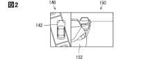
画像生成部114は、表示部131に表示する種々の画像を生成する。画像生成部114が生成する画像には、周辺画像140と後方通路画像150とが含まれる。周辺画像140は、周辺領域を一部または全部とする画像である。図2に周辺画像140の一例を示している。図2に示す周辺画像140は、自車両2を真上から見た俯瞰画像である。この周辺画像140は、自車両2の前後左右に備えられたカメラ11から合成できる画像である。周辺画像140には、自車両2の位置を示すための自車両図形142が配置されている。自車両図形142は、自車両2を上から見た図形である。 The
図2には、後方通路画像150も示されている。図2では、周辺画像140と後方通路画像150は隣接して配置されている。後方通路画像150は、後側方通路領域151(図3参照)を含んだ画像である。後側方通路領域151は、自車両2の後側方にある通路を含んだ領域である。さらに、図2に示す後方通路画像150には、後方通路画像150にある通路などと自車両2との相対位置を分かりやすくするために、自車両2の前端面の一部を表す自車両図形152が配置されている。 Also shown in FIG. 2 is a
図3には、図2に例示した後方通路画像150についての仮想カメラ位置160を示している。図3に示す自車両2は、駐車区画3から出て道路4に進入しようとしている状態である。 FIG. 3 shows a
仮想カメラ位置160は、後方通路画像150の仮想視点を意味する。仮想視点は、後方通路画像150を撮影するとした場合の仮想のカメラ位置である。図3に示す仮想カメラ位置160は、自車両2よりも前方かつ上方に位置する。周辺画像140の視点が自車両2の真上にあることから、後方通路画像150は周辺画像140とは異なる視点からの画像である。 The
仮想カメラ位置160からの画像である後方通路画像150は、1つあるいは複数のカメラ11から得られた撮影データが示す撮影画像に写っている各座標を座標変換処理することにより、得ることができる。座標変換は、カメラ11の取り付け位置、撮影画像上の各座標の位置、仮想カメラ位置160をもとにして行う。 The
なお、図2に示す後方通路画像150は、仮想カメラ位置160を仮想視点とする画像ではあるが、左右は、仮想カメラ位置160から実際に後側方通路領域151を見たときとは反転させている。理由は、左右を反転させることで、実空間での自車両2通路との左右関係と、後方通路画像150で表示されている自車両図形152と通路との左右関係が一致させるためである。後方通路画像150をこのような画像とすることで、自車両2の乗員が、後方通路画像150にある通路と実空間にある通路とを対応づけやすい。ただし、後方通路画像150を、仮想カメラ位置160から実際に後側方通路領域151を見たときの左右と一致する画像とすることもできる。 Note that the
後方通路画像150は、後側方通路領域151を含んだ画像であり、後側方通路領域151は、自車両2の後側方にある通路を含んだ領域である。自車両2はその通路に対して斜めに進入する。後側方は、進入しようとしている通路に対して斜めに進入する状態の自車両2における後側方である。あるいは、後側方は、進入しようとしている通路に対して自車両2の前後方向が平行になっている状態での後側方とすることもできる。後側方通路領域151は、周辺領域よりも、通路において自車両2よりも進入方向後方となる部分を十分に含む領域である。なお、進入方向は、自車両2が通路に進入したあとの進行方向を意味する。後側方通路領域151は、たとえば、通路において自車両2のすぐ側方から自車両2よりも後方の数十メートルまでを含む領域である。 The
図2に例示しているように、本実施形態では、周辺画像140と後方通路画像150が同時に表示される。このように周辺画像140と後方通路画像150を同時に表示する理由は、次の通りである。 As illustrated in FIG. 2, in this embodiment, the
図3に示すように、自車両2が駐車区画3から自車両2の右側にある道路4に出る場合、自車両2を右前方へ旋回させる。このときは、自車両2の左前角部2aが前方に停車している他車両5などの障害物に接触しないように注意する必要がある。 As shown in FIG. 3, when the
また、自車両2の一部が道路4に入った後は、自車両2を左前方向に旋回させる。このときは、自車両2の左後輪付近である左後側部2bが他車両5などの障害物に接触しないように注意する必要がある。周辺画像140は、自車両2の左前角部2aや左後側部2bが障害物と接触しないかどうかを自車両2の乗員が確認するために用いる画像である。 Further, after a part of the
さらに、図3の状況では、周辺画像140に写っている周辺領域を確認する必要があることに加えて、同時に、道路4を自車両2の方向に移動してくる車や人などの移動体にも注意する必要がある。そこで、周辺画像140と同時に、後方通路画像150を表示部131に表示するのである。 Furthermore, in the situation of FIG. 3, in addition to the need to check the surrounding area shown in the
出力制御部115は、画像生成部114が生成した周辺画像140、後方通路画像150などの画像を示す画像データをディスプレイ130に出力する。表示部131には、出力制御部115から出力された画像データをもとにした種々の画像が表示される。また、出力制御部115は、スピーカ120に警告音などの音を発生させるための信号をスピーカ120に出力するようになっていてもよい。 The
〔ECU110が実行する処理〕
図4にECU110が実行する処理を示す。図4に示す処理を開始する開始条件は、種々、設定できる。図4に示す処理は、表示部131に、前述した周辺画像140、または、周辺画像140と後方通路画像150を表示させる処理である。これらの画像は、駐車区画3から自車両2が前進発進するときなどに利用する。したがって、駐車後の発進開始を、開始条件とすることができる。また、走行中であっても、駐車場から道路4に入るときにも周辺領域を確認する必要がある。また、狭い道路から広い道路に入るときにも周辺領域を確認する必要がある。このときの走行速度は、駐車場から道路4に入るときと同程度である。そこで、駐車場を走行する程度の低速走行となったことを開始条件とすることもできる。また、乗員による開始操作があったことを、開始条件成立とすることもできる。 [Processing executed by ECU 110]
FIG. 4 shows the processing executed by the
さらには、自車両2の現在位置を取得し、地図データにおける自車両2の位置が、駐車場から道路4に入る位置など、予め設定された処理開始位置であることを開始条件とすることもできる。また、地図データにおける自車両2の位置に代えて、カメラ11から取得する撮影データを画像解析することで、自車両2の位置を決定してもよい。 Furthermore, the current position of the
ステップ(以下、ステップを省略)S1では撮影データ取得部111が、カメラ11から撮影データを取得する。S2以下は画像生成部114が実行する。S2では、通路に対する自車両2の位置を算出する。通路に対する自車両2の位置を算出するために、たとえば、撮影データを解析して通路領域を決定する。 In step (hereinafter, step is omitted) S1, the photographic
通路領域を決定するために、駐車区画3の枠線の位置を決定し、枠線を通路との境界とし、枠線よりも通路方向を通路領域とすることができる。駐車区画3を規定する枠がない場合、あるいは、枠が認識できない場合でも、前または後ろに他車両5が駐車している場合には、他車両5の通路側の側面あるいはその側面から一定距離だけ通路側の位置を通路と通路外との境界としてもよい。さらに、前述したように、通路には歩道も含まれる。歩道は、隣接する駐車場、車庫、道路との境界は明確である。したがって、通路が歩道である場合の通路領域は、画像解析により決定することができる。 In order to determine the passage area, the position of the frame line of the
通路領域に対する自車両2の位置も、撮影データを解析して決定することができる。ここでの自車両2の位置は、自車両2において通路に近い部分の位置である。たとえば、ここでの自車両2の位置は、自車両2の通路側の側面とする。また、自車両2の位置を、自車両2の左右の前輪のうち通路側の前輪の位置とすることもできる。 The position of the
S3では、S2で算出した自車両2の位置をもとに、自車両2が通路に差し掛かっているか否かを判断する。S3の判断結果がNOであればS4に進む。S4では、それまでの表示画像を継続して表示する。たとえば、S4を実行する時点で、周辺画像140は表示しているが、後方通路画像150は表示していない状態であれば、周辺画像140は継続して表示する。S3の判断結果がYESであればS5に進む。S5以下を実行する場合、以下に説明するように、後方通路画像150を生成する。したがって、S3の判断条件は、後方通路画像150を生成する画像生成条件である。 In S3, it is determined whether or not the
S5では、自車両2が前進走行により入ろうとしている通路の通路境界線と、自車両2の相対位置、および、通路境界線に対する自車両2の相対角度を算出する。相対位置の算出はS2と同じである。相対角度も、撮影データを画像解析して決定することができる。 In S5, the relative position of the
S6では、S5で決定した相対位置、相対角度に基づいて、仮想カメラ位置160と仮想カメラの向きを決定する。仮想カメラ位置160と仮想カメラの向きは、図3に例示したように、自車両2を基準として定まる後側方通路領域151が含まれる後方通路画像150を撮影するとした場合の仮想のカメラ位置である。仮想カメラ位置160は、自車両2の所定点を基準点として、そこから、x、y、z方向にそれぞれ予め設定したdx、dy、dyだけ移動した点である。仮想カメラの向きは、自車両2に設定した基準面、たとえば、車幅方向中心を通り自車両2の前後方向に平行な鉛直面に対して、一定角度、通路方向に傾いた角度とすることができる。 In S6, the
なお、仮想カメラの向きは、自車両2の相対角度ではなく、通路領域が延びる方向を基準として決定してもよい。通路領域が延びる方向は、地図上の自車両2の位置を自車両2の座標などから決定し、決定した自車両2の位置において通路が延びている方向とすることができる。 Note that the direction of the virtual camera may be determined based on the direction in which the passage area extends, rather than the relative angle of the
S7では、車両情報入出力部112から周辺の障害物との距離を取得する。S8では、最新の撮影データをもとに周辺画像140と後方通路画像150とを表す画像データを生成(すなわち描画)して、それらの画像データを出力制御部115に出力する。出力制御部115は、その画像データをディスプレイ130に出力するので、表示部131に周辺画像140と後方通路画像150が表示される。ここで、S7で取得した距離のうちの最短距離が要注意距離閾値以上であれば、自車両図形142が周辺画像140の中心に位置する周辺画像140を描画する。この周辺画像140の一例は、図2に示す周辺画像140である。要注意距離閾値は、自車両2と障害物が接触しないように、特に注意する必要がある距離であって、実験等に基づいて予め設定される距離である。 In S7, distances to surrounding obstacles are acquired from the vehicle information input/
最短距離が要注意距離閾値よりも短い場合には、その最短距離となっている部分が分かりやすくなる周辺画像140を描画する。たとえば、自車両図形142が周辺画像140の中央にある場合よりも、最短距離となっている部分が周辺画像140の中央寄りになる周辺画像140を描画する。あるいは、最短距離となっている部分が要注意距離閾値以上であるときよりも、最短距離となっている部分が拡大されている周辺画像140を描画する。最短距離となっている部分が拡大されている周辺画像140を描画する場合、要注意距離閾値は、周辺画像140を拡大するかどうかを決める閾値すなわち拡大距離閾値である。 If the shortest distance is shorter than the caution-required distance threshold, a
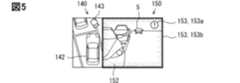
図5に示す周辺画像140は、最短距離が要注意距離閾値よりも短くなっているときの周辺画像140である。図5の周辺画像140において最短距離となっている部分は、自車両2の左前角部2aである。図5の周辺画像140は、自車両2の左前角部2aが周辺画像140の中央付近になるように、自車両図形142が周辺画像140の右下にある。また、図5の周辺画像140は、図2の周辺画像140よりも自車両2の左前角部2aが拡大されている。 The
また、図5の周辺画像140には、視点位置画像143が表示されている。視点位置画像143は、周辺画像140と同時に表示されている後方通路画像150の視点を示すものである。後方通路画像150の視点の位置は、後方通路画像150を描画する際に決定されている。自車両図形142に対する視点位置画像143の位置が、自車両2に対する後方通路画像150の視点の位置を示すように、周辺画像140における視点位置画像143の位置を決定する。 Furthermore, a
S9では、後方通路の確認処理をし、後方通路の確認結果を示す画像を描画して、その画像を表す画像データを出力制御部115に出力する。後方通路の確認処理は、後側方通路領域151に、自車両2の方向に向かって移動する移動体があるかどうかを確認する処理である。確認処理は、後方通路画像150を生成する際に用いた撮影データを解析することで行う。 In S9, the rear passage confirmation process is performed, an image showing the confirmation result of the rear passage is drawn, and image data representing the image is output to the
図5には、確認結果を示す画像である2種類の注意喚起画像153a、153bが示されている。これら2種類の注意喚起画像153a、153bを区別しないときは注意喚起画像153とする。後方通路画像150には、自車両2に接近する他車両5が写っている。したがって、他車両5に対する注意喚起を促すために、確認結果を示す画像として、注意喚起画像153を表示する。注意喚起画像153aは、後方通路画像150の隅部に重畳された画像である。注意喚起画像153bは後方通路画像150の枠を強調する画像である。 FIG. 5 shows two types of attention-calling images 153a and 153b, which are images showing confirmation results. When these two types of attention-calling images 153a and 153b are not distinguished, they are referred to as attention-calling images 153. The
図6には、確認処理の結果、後側方通路領域151に自車両2に接近する移動体が写っていない場合に表示する確認結果画像154が示されている。 FIG. 6 shows a
S10では、周辺画像140と後方通路画像150の同時表示を終了するか否かを判断する。たとえば、自車両2の全部が通路に入った場合にS10の判断結果をYESとし、自車両2の一部がまだ通路に入っていない場合にはS10の判断結果をNOとする。S10の判断結果がNOであればS5に戻る。 In S10, it is determined whether or not to end the simultaneous display of the
なお、S5からS10の繰り返しにおいて、2度目以降のS6では、仮想カメラの向きは、自車両2の向きの変更に伴い、逐次、変更してもよい。しかし、2度目以降のS6では、仮想カメラの向きは、1回目のS6で決定した向きのままとしてもよい。 Note that in repeating S5 to S10, the orientation of the virtual camera may be sequentially changed in S6 from the second time onward as the orientation of the
S10の判断結果がYESであればS11へ進む。S11では、図4の処理を終了するか否かを判断する。自車両2の速度が駐車後の発進時に想定される低速域を超えた場合には、周辺画像140も表示する必要がない。そこで、たとえば、自車両2の速度が上記低速域を超えた場合に、図4の処理を終了する。S11の判断結果がNOであればS3に戻る。 If the determination result in S10 is YES, the process advances to S11. In S11, it is determined whether or not to end the process of FIG. If the speed of the
〔実施形態のまとめ〕
この実施形態で説明した車両用表示装置100は、表示部131に、周辺画像140と後方通路画像150が同時に表示される。したがって、表示部131を見れば、自車両2の後側方にある通路と、自車両2の周辺とを同時に確認することができる。よって、出庫時などにおいて確認すべき領域を容易に確認することができる。 [Summary of embodiments]
In the
画像生成部114は、自車両2が通路に差し掛かっていると判断した場合に、後方通路画像150を表示部131に表示する。したがって、後側方通路領域151を確認する必要性が高いときに後方通路画像150が表示される。また、後側方通路領域151を確認する必要性が低いときには後方通路画像150は表示されないので、表示部131の表示領域を有効に活用できる。 The
後方通路画像150は、自車両2の前方にある仮想カメラ位置160から見た画像であり、後方通路画像150には、自車両2の前端面の一部を表した図形である自車両図形152が含まれている。したがって、後方通路画像150は、後側方通路領域151と自車両2との関係が認識しやすい。 The
また、後方通路画像150と同時に表示される周辺画像140に、後方通路画像150の仮想視点を示す視点位置画像143が表示される。これによっても、後方通路画像150がどの領域を撮影した画像であるかが分かりやすくなる。 Furthermore, a
画像生成部114は、自車両2と障害物との最短距離が要注意距離閾値よりも短くなった場合、最短距離が要注意距離閾値よりも長い場合よりも、最短距離が要求位距離閾値よりも短くなった箇所を拡大した周辺画像140(図6)を生成する(S8)。よって、周辺画像140を見ることで、自車両2の乗員は、より容易に自車両2が障害物と接触しそうかどうかを判断できる。 When the shortest distance between the
後方通路画像150に自車両2に接近する移動体が写っている場合、注意喚起画像153が表示部131に表示される。注意喚起画像153が表示されることでも、後方通路画像150を見る乗員は、その移動体の存在を認識しやすい。 When the
また、後方通路画像150に自車両2に接近する移動体が写っていない場合には、後側方通路領域151に自車両2に接近する移動体が存在しないことを示す確認結果画像154が表示部131に表示される。よって、確認結果画像154を見ることで、自車両2の乗員は、後側方通路領域151に自車両2に接近する移動体が存在しないことを判断しやすい。 Furthermore, if the
以上、実施形態を説明したが、開示した技術は上述の実施形態に限定されるものではなく、次の変形例も開示した範囲に含まれ、さらに、下記以外にも要旨を逸脱しない範囲内で種々変更して実施できる。なお、以下の説明において、それまでに使用した符号と同一番号の符号を有する要素は、特に言及する場合を除き、それ以前の実施形態における同一符号の要素と同一である。また、構成の一部のみを説明している場合、構成の他の部分については先に説明した実施形態を適用できる。 Although the embodiments have been described above, the disclosed technology is not limited to the above-mentioned embodiments, and the following modifications are also included within the disclosed scope, and furthermore, other than the following may be included within the scope of the gist. It can be implemented with various modifications. In the following description, elements having the same reference numerals as those used up to that point are the same as elements having the same reference numerals in the previous embodiments, unless otherwise specified. Further, when only a part of the configuration is described, the embodiment described above can be applied to other parts of the configuration.
<変形例1>
実施形態では、自車両2を前方の仮想カメラ位置160から見た後方通路画像150を表示していた。しかし、後方通路画像150に代えて、図7に示す後方通路画像250のように自車両2の側面に設置されたサイドカメラが撮影した画像を表示してもよい。後方通路画像250にも、後側方通路領域151が写っている。また、後方通路画像250には、自車両2の側面が写っている。したがって、後方通路画像250も、その画像から、自車両2と後側方通路領域151との関係を把握することができる。また、後方通路画像150は複数のカメラ11が撮影した画像を合成して生成する必要があるのに対して、後方通路画像250は、1つのサイドカメラが撮影した画像のみから生成できる。よって、画像を生成するための演算処理を少なくできる。 <Modification 1>
In the embodiment, the
<変形例2>
実施形態で説明した周辺画像140は、自車両図形142が画像の中心に位置していた。しかし、図3を用いて説明たように、自車両2が、自車両2の右側にある通路に入るときは、自車両2の左側面に注意する必要がある。反対に、自車両2が、自車両2の左側にある通路に入るときは、自車両2の右側面に注意する必要がある。そこで、図8に示す周辺画像240のように、障害物との距離によらず、自車両2よりも通路から遠い側が広く映るようにしてもよい。図8に示す周辺画像240は、右側に通路があるので、周辺画像240の右端下端に自車両図形142が位置する画像となっている。 <
In the
<変形例3>
実施形態では、仮想カメラの向きを、自車両2に対する相対角度として決定していた。しかし、後方通路画像150に後側方通路領域151が写っていればよいので、仮想カメラの向きは、通路の延びる方向を基準とした固定角度としてもよい。 <
In the embodiment, the direction of the virtual camera is determined as a relative angle with respect to the
<変形例4>
実施形態では、縦列駐車している状態から道路4に入る例を説明した。しかし、車両用表示装置100は、他車両5に対して並列に駐車している状態から走行開始する場合にも適用できる。 <
In the embodiment, an example has been described in which the vehicle enters the
図9には、並列駐車状態から走行開始する場合の後側方通路領域151などを示している。図9では、駐車している状態の自車両2の前方には、道路4を挟んで壁6がある。図9に示す場合には、駐車区画3から道路4に入る自車両2は、左後側部2bと右前角部2cが障害物に接触しないように特に注意する必要がある。図9における後側方通路領域151は、自車両2の全部が駐車区画3内に位置しているときは、自車両2の側方であるが、自車両2が道路4に入る状態では自車両2の後側方にある。仮想カメラ位置160は、自車両2の前方であって後側方通路領域151が映る位置である。 FIG. 9 shows the rear
また、縦列駐車、並列駐車以外にも、自車両2が駐車場から道路4に入るとき、狭い道路から、徐行により広い道路に合流する場合に図4に処理を実行してもよい。 In addition to parallel parking and parallel parking, the process shown in FIG. 4 may be executed when the
<変形例5>
実施形態では、画像生成条件成立を、自車両2が通路に差し掛かっている状態であることとしていた。しかし、実際に自車両2が通路に差し掛かかる前であっても、自車両2の一部が通路に入ることが予想される状態となったことを画像生成条件成立としてもよい。自車両2の一部が通路に入ることが予想される状態とは、自車両2が走行予定の予測軌道を逐次計算しており、その予測軌道が、自車両2が障害物に接触せずに道路4に入ることができる軌道になった状態である。 <
In the embodiment, the image generation condition is satisfied when the
また、予測軌道を逐次算出している場合、周辺画像140、240に、予測軌道を示す予測軌道線を重畳してもよい。 Further, when the predicted trajectory is calculated sequentially, a predicted trajectory line indicating the predicted trajectory may be superimposed on the
<変形例6>
実施形態では、周辺画像140はカメラ11が撮影した撮影データを画像変換して生成した俯瞰画像であった。しかし、周辺画像は、カメラ11が撮影した撮影画像そのもの、カメラ11が撮影した画像から周辺領域を切り取った画像など、俯瞰画像以外の画像でもよい。 <
In the embodiment, the
<変形例7>
本開示に記載の制御部およびその手法は、コンピュータプログラムにより具体化された一つ乃至は複数の機能を実行するようにプログラムされたプロセッサを構成する専用コンピュータにより、実現されてもよい。あるいは、本開示に記載の制御部およびその手法は、専用ハードウエア論理回路により、実現されてもよい。もしくは、本開示に記載の制御部およびその手法は、コンピュータプログラムを実行するプロセッサと一つ以上のハードウエア論理回路との組み合わせにより構成された一つ以上の専用コンピュータにより、実現されてもよい。ハードウエア論理回路は、たとえば、ASIC、FPGAである。 <Modification 7>
The controller and techniques described in this disclosure may be implemented by a dedicated computer comprising a processor programmed to perform one or more functions embodied by a computer program. Alternatively, the controller and techniques described in this disclosure may be implemented by dedicated hardware logic circuits. Alternatively, the control unit and the method described in the present disclosure may be realized by one or more dedicated computers configured by a combination of a processor that executes a computer program and one or more hardware logic circuits. The hardware logic circuit is, for example, an ASIC or an FPGA.
また、コンピュータプログラムを記憶する記憶媒体はROMに限られず、コンピュータにより実行されるインストラクションとして、コンピュータ読み取り可能な非遷移有形記録媒体に記憶されていればよい。たとえば、フラッシュメモリに上記プログラムが記憶されていてもよい。 Furthermore, the storage medium that stores the computer program is not limited to the ROM, but may be any computer-readable non-transitional tangible recording medium that stores the computer program as instructions to be executed by the computer. For example, the program may be stored in a flash memory.
2:自車両 2a:左前角部 2b:左後側部 2c:右前角部 3:駐車区画 4:道路(通路) 5:他車両 6:壁 10:車載システム 11:カメラ 12:測距センサ 13:車輪速センサ 14:操舵制御部 15:シフト制御部 16:アクセル制御部 17:ブレーキ制御部 18:車内ネットワーク線 100:車両用表示装置 110:ECU 111:撮影データ取得部 112:車両情報入出力部 113:画像認識部 114:画像生成部 115:出力制御部 120:スピーカ 130:ディスプレイ 131:表示部 132:操作入力部 140:周辺画像 142:自車両図形 143:視点位置画像 150:後方通路画像 151:後側方通路領域 152:自車両図形 153:注意喚起画像 154:確認結果画像 160:仮想カメラ位置 240:周辺画像 250:後方通路画像2:
Claims (13)
Translated fromJapanese自車両(2)の進入しようとしている通路の進入方向後方を含んだ後側方通路領域と、前記自車両の周辺が含まれる周辺領域とが撮影された撮影データを取得する撮影データ取得部(111)と、
前記撮影データ取得部が取得した前記撮影データをもとに、前記後側方通路領域の画像と前記周辺領域の画像とを生成する画像生成部(114)と、
前記後側方通路領域の画像と前記周辺領域の画像とを同時に表示する表示部(131)とを備え、
前記画像生成部は、前記後側方通路領域を含む画像である後方通路画像(150、250)と、前記周辺領域を含む画像であって前記後方通路画像とは異なる視点からの画像である周辺画像(140、240)とを生成し、
前記後方通路画像は、仮想視点(160)から、前記後側方通路領域を見た画像であり、
前記画像生成部は、前記後方通路画像の前記仮想視点を示す視点位置画像(143)を、前記表示部に表示する、車両用表示装置。A display device fora vehicle , comprising:
a photographic data acquisition unit that acquires photographic data of a rear side passage area including the rear side in the entry direction of the passage into whichthe own vehicle (2) is about to enter, and a peripheral area including the surrounding area of the own vehicle; 111) and
an image generation unit (114) that generates an image of the rear side passage area and an image of the peripheral area based on the photography data acquired by the photography data acquisition unit;
comprising a display unit (131) that simultaneously displays an image of the rear side passageway area and an image of the peripheral area,
The image generation unit generates a rear passage image (150, 250) that is an image that includes the rear side passage area, and a peripheral image that is an image that includes the peripheral area and is an image from a different viewpoint than the rear passage image. generate images (140, 240);
The rear passage image is an image of the rear side passage area viewed from avirtual viewpoint (160),
The image generation section is a vehicle display device that displays a viewpoint position image (143) indicating the virtual viewpoint of the rear passage image on the display section .
自車両(2)の進入しようとしている通路の進入方向後方を含んだ後側方通路領域と、前記自車両の周辺が含まれる周辺領域とが撮影された撮影データを取得する撮影データ取得部(111)と、
前記撮影データ取得部が取得した前記撮影データをもとに、前記後側方通路領域の画像と前記周辺領域の画像とを生成する画像生成部(114)と、
前記後側方通路領域の画像と前記周辺領域の画像とを同時に表示する表示部(131)とを備え、
前記画像生成部は、前記後側方通路領域を含む画像である後方通路画像(150、250)と、前記周辺領域を含む画像であって前記後方通路画像とは異なる視点からの画像である周辺画像(140、240)とを生成し、
前記後方通路画像は、仮想視点(160)から、前記後側方通路領域を見た画像であり、
前記画像生成部は、逐次、前記後方通路画像と前記周辺画像を生成するものであって、前記仮想視点は前記自車両に対する角度が固定されている、車両用表示装置。A display device for a vehicle, comprising:
a photographic data acquisition unit that acquires photographic data of a rear side passage area including the rear side in the entry direction of the passage into which the own vehicle (2) is about to enter, and a peripheral area including the surrounding area of the own vehicle; 111) and
an image generation unit (114) that generates an image of the rear side passage area and an image of the peripheral area based on the photography data acquired by the photography data acquisition unit;
comprising a display unit (131) that simultaneously displays an image of the rear side passageway area and an image of the peripheral area,
The image generation unit generates a rear passage image (150, 250) that is an image that includes the rear side passage area, and a peripheral image that is an image that includes the peripheral area and is an image from a different viewpoint than the rear passage image. generate images (140, 240);
The rear passage image is an image of the rear side passage area viewed from a virtual viewpoint (160),
The image generation unitsequentially generates the rear passage image and the surrounding image, and the virtual viewpoint has a fixed angle with respect to the host vehicle .
自車両(2)の進入しようとしている通路の進入方向後方を含んだ後側方通路領域と、前記自車両の周辺が含まれる周辺領域とが撮影された撮影データを取得する撮影データ取得部(111)と、
前記撮影データ取得部が取得した前記撮影データをもとに、前記後側方通路領域の画像と前記周辺領域の画像とを生成する画像生成部(114)と、
前記後側方通路領域の画像と前記周辺領域の画像とを同時に表示する表示部(131)とを備え、
前記画像生成部は、前記後側方通路領域を含む画像である後方通路画像(150、250)と、前記周辺領域を含む画像であって前記後方通路画像とは異なる視点からの画像である周辺画像(140、240)とを生成し、
前記後方通路画像は、仮想視点(160)から、前記後側方通路領域を見た画像であり、
前記画像生成部は、逐次、前記後方通路画像と前記周辺画像を生成するものであって、前記仮想視点は前記通路に対する角度が固定されている、車両用表示装置。A display device for a vehicle, comprising:
a photographic data acquisition unit that acquires photographic data of a rear side passage area including the rear side in the entry direction of the passage into which the own vehicle (2) is about to enter, and a peripheral area including the surrounding area of the own vehicle; 111) and
an image generation unit (114) that generates an image of the rear side passage area and an image of the peripheral area based on the photography data acquired by the photography data acquisition unit;
comprising a display unit (131) that simultaneously displays an image of the rear side passageway area and an image of the peripheral area,
The image generation unit generates a rear passage image (150, 250) that is an image that includes the rear side passage area, and a peripheral image that is an image that includes the peripheral area and is an image from a different viewpoint than the rear passage image. generate images (140, 240);
The rear passage image is an image of the rear side passage area viewed from a virtual viewpoint (160),
The image generation unit sequentially generates the rear passage image and the peripheral image, and the virtual viewpoint has a fixed angle with respect tothepassage .
前記画像生成部は、前記後方通路画像の前記仮想視点を示す視点位置画像(143)を、前記表示部に表示する、車両用表示装置。The vehicle display deviceaccording to claim 2 or 3 ,
The image generation section is avehicle display devicethat displays a viewpoint position image (143) indicating the virtual viewpoint of the rear passage image on the display section .
自車両(2)の進入しようとしている通路の進入方向後方を含んだ後側方通路領域と、前記自車両の周辺が含まれる周辺領域とが撮影された撮影データを取得する撮影データ取得部(111)と、
前記撮影データ取得部が取得した前記撮影データをもとに、前記後側方通路領域の画像と前記周辺領域の画像とを生成する画像生成部(114)と、
前記後側方通路領域の画像と前記周辺領域の画像とを同時に表示する表示部(131)とを備え、
前記画像生成部は、前記後側方通路領域を含む画像である後方通路画像(150、250)と、前記周辺領域を含む画像であって前記後方通路画像とは異なる視点からの画像である周辺画像(140、240)とを生成し、
前記画像生成部は、前記周辺領域に含まれる前記自車両の一部と障害物との間の距離が拡大距離閾値よりも短くなった場合に、前記距離が前記拡大距離閾値よりも長い場合よりも、前記距離が前記拡大距離閾値よりも短くなった箇所を拡大した前記周辺画像を生成する、車両用表示装置。A display device fora vehicle , comprising:
a photographic data acquisition unit that acquires photographic data of a rear side passage area including the rear side in the entry direction of the passage into whichthe own vehicle (2) is about to enter, and a peripheral area including the surrounding area of the own vehicle; 111) and
an image generation unit (114) that generates an image of the rear side passage area and an image of the peripheral area based on the photography data acquired by the photography data acquisition unit;
comprising a display unit (131) that simultaneously displays an image of the rear side passageway area and an image of the peripheral area,
The image generation unit generates a rear passage image (150, 250) that is an image that includes the rear side passage area, and a peripheral image that is an image that includes the peripheral area and is an image from a different viewpoint than the rear passage image. generate images (140, 240);
When the distance between the part of the host vehicle included in the surrounding area and the obstacle is shorter than the enlarged distance threshold, the image generation unit may be configured to generate Also, the vehicle display device generates the peripheral image in which a portion where the distance becomes shorter than the enlargement distance threshold is enlarged.
前記通路には歩道が含まれ、
前記画像生成部は、前記自車両の少なくとも一部が前記歩道に入っている状態、または、前記自車両の一部が前記歩道に入ることが予想される状態であることを画像生成条件として、前記後方通路画像を生成する、車両用表示装置。 The vehicle display device according to claim8 ,
The passageway includes a sidewalk;
The image generation unitsets, as an image generation condition, that at least a part of the host vehicle is on the sidewalk, or that a part of the host vehicle is expected to enter the sidewalk, A vehicle display devicethat generates the rear passage image .
前記画像生成部は、前記後側方通路領域に前記自車両に接近する移動体が写っている場合、前記移動体に対する注意喚起を前記自車両の乗員に促す注意喚起画像(153)を前記表示部に表示する、車両用表示装置。 The vehicle display device according to any one of claims 1 to 9,
When a moving object approaching the own vehicleis shown in the rear side passage area, the image generation unit displaysan alerting image (153) that urges the occupants of the own vehicle to be careful about the moving object. A vehicle display device that displays information on the vehicle.
前記画像生成部は、前記後側方通路領域に前記自車両に接近する移動体が写っていない場合、前記後側方通路領域に前記自車両に接近する移動体が存在しないことを示す画像(154)を前記表示部に表示する、車両用表示装置。The vehicle display device according to any one of claims 1 to 10,
When the moving object approaching the host vehicle is not captured in the rear side passage area, the image generation unit generates an image ( 154) on the display section.
自車両(2)の進入しようとしている通路の進入方向後方を含んだ後側方通路領域と、前記自車両の周辺が含まれる周辺領域とが撮影された撮影データを取得する撮影データ取得部(111)と、
前記撮影データ取得部が取得した前記撮影データをもとに、前記後側方通路領域を含む画像情報である後方通路画像(150、250)と、前記周辺領域を含む画像情報であって前記後方通路画像とは異なる視点からの画像である周辺画像(140、240)とを出力する出力部(114)とを備え、
前記後方通路画像は、仮想視点(160)から、前記後側方通路領域を見た画像情報であり、
前記出力部は、前記後方通路画像を表示する際の前記仮想視点の位置を示す視点位置画像情報(143)を出力する、車両用表示装置。A display device fora vehicle , comprising:
a photographic data acquisition unit that acquires photographic data of a rear side passage area including the rear side in the entry direction of the passage into which the own vehicle (2) is about to enter, and a peripheral area including the surrounding area of the own vehicle; 111) and
Based on the photographic data acquired by the photographic data acquisition unit, a rear passage image (150, 250) is image information including the rear side passage area, and a rear passage image (150, 250) is image information including the peripheral area. an output unit (114) that outputs peripheral images (140, 240) that are images from a different viewpoint than the passage image;
The rear passage image is image information when viewing the rear side passage area from a virtual viewpoint (160),
The output unit is a vehicle display device thatoutputs viewpoint position image information (143) indicatingthe position of the virtual viewpointwhen displaying the rear passage image.
前記撮影データをもとに、前記後側方通路領域を含む画像である後方通路画像(150、250)と、前記周辺領域を含む画像であって前記後方通路画像とは異なる視点からの画像である周辺画像(140、240)とを生成して、前記後側方通路領域の画像と前記周辺領域の画像とを同時に表示部に表示し(S8)、
前記周辺画像は、前記周辺領域に含まれる自車両の一部と障害物との間の距離が拡大距離閾値よりも短くなった場合に、前記距離が前記拡大距離閾値よりも長い場合よりも、前記距離が前記拡大距離閾値よりも短くなった箇所を拡大した画像である、車両用表示方法。 Obtaining photographic data in which a rear side passage area including the rear side in the entry direction of the passage into which the vehicle is about to enter and a surrounding area including the surroundings of the vehicle are acquired (S1);
Based on the photographic data, a rear passage image (150, 250) that is an image that includes the rear side passage area, and an image that includes the peripheral area and is taken from a different viewpoint from the rear passage image. generating a certain surrounding image (140, 240) and simultaneously displaying the image of the rear side passage area and the image of the surrounding area on a display unit (S8);
In the surrounding image, when the distance between a part of the own vehicle included in the surrounding area and an obstacle is shorter than the enlarged distance threshold, the distance is longer than the enlarged distance threshold. A display method for a vehicle, wherein the image is an enlarged image of a portion where the distance is shorter than the enlargement distance threshold.
Priority Applications (4)
| Application Number | Priority Date | Filing Date | Title |
|---|---|---|---|
| JP2020050365AJP7424144B2 (en) | 2020-03-20 | 2020-03-20 | Vehicle display device and vehicle display method |
| CN202180021476.1ACN115280765A (en) | 2020-03-20 | 2021-03-03 | Vehicle display device and vehicle display method |
| DE112021001735.7TDE112021001735T5 (en) | 2020-03-20 | 2021-03-03 | Vehicle display device and vehicle display method |
| PCT/JP2021/008249WO2021187118A1 (en) | 2020-03-20 | 2021-03-03 | Automotive display device and automotive display method |
Applications Claiming Priority (1)
| Application Number | Priority Date | Filing Date | Title |
|---|---|---|---|
| JP2020050365AJP7424144B2 (en) | 2020-03-20 | 2020-03-20 | Vehicle display device and vehicle display method |
Publications (3)
| Publication Number | Publication Date |
|---|---|
| JP2021150873A JP2021150873A (en) | 2021-09-27 |
| JP2021150873A5 JP2021150873A5 (en) | 2022-05-25 |
| JP7424144B2true JP7424144B2 (en) | 2024-01-30 |
Family
ID=77768101
Family Applications (1)
| Application Number | Title | Priority Date | Filing Date |
|---|---|---|---|
| JP2020050365AActiveJP7424144B2 (en) | 2020-03-20 | 2020-03-20 | Vehicle display device and vehicle display method |
Country Status (4)
| Country | Link |
|---|---|
| JP (1) | JP7424144B2 (en) |
| CN (1) | CN115280765A (en) |
| DE (1) | DE112021001735T5 (en) |
| WO (1) | WO2021187118A1 (en) |
Families Citing this family (2)
| Publication number | Priority date | Publication date | Assignee | Title |
|---|---|---|---|---|
| JP2023082954A (en)* | 2021-12-03 | 2023-06-15 | 本田技研工業株式会社 | Control apparatus, control method, and control program |
| CN119380567A (en)* | 2023-07-25 | 2025-01-28 | 华为技术有限公司 | Driving risk prompting method and device, and vehicle |
Citations (4)
| Publication number | Priority date | Publication date | Assignee | Title |
|---|---|---|---|---|
| JP2016220011A (en) | 2015-05-20 | 2016-12-22 | 株式会社デンソー | Image processing apparatus, electronic mirror system, and image processing method |
| JP2018034651A (en) | 2016-08-31 | 2018-03-08 | 本田技研工業株式会社 | Pull-out-of-parking support device |
| JP2019110389A (en) | 2017-12-15 | 2019-07-04 | 株式会社東海理化電機製作所 | Vehicle periphery monitoring device |
| JP2019110448A (en) | 2017-12-19 | 2019-07-04 | クラリオン株式会社 | Display control device and display system |
Family Cites Families (8)
| Publication number | Priority date | Publication date | Assignee | Title |
|---|---|---|---|---|
| JP2001071790A (en)* | 1999-09-07 | 2001-03-21 | Mazda Motor Corp | Vehicle display device |
| EP1083076A3 (en)* | 1999-09-07 | 2005-01-12 | Mazda Motor Corporation | Display apparatus for vehicle |
| US7258446B2 (en) | 2005-01-27 | 2007-08-21 | Dell Products L.P. | System and method for intelligent information handling system projector cool down |
| JP5058491B2 (en)* | 2006-02-09 | 2012-10-24 | 日産自動車株式会社 | VEHICLE DISPLAY DEVICE AND VEHICLE VIDEO DISPLAY CONTROL METHOD |
| JP6326869B2 (en)* | 2014-03-05 | 2018-05-23 | 株式会社デンソー | Vehicle periphery image display device and vehicle periphery image display method |
| JP2017076833A (en)* | 2015-10-13 | 2017-04-20 | アルパイン株式会社 | Driving support device and computer program |
| JP7069692B2 (en)* | 2017-12-20 | 2022-05-18 | トヨタ自動車株式会社 | Image display device |
| JP6625157B2 (en)* | 2018-04-06 | 2019-12-25 | 株式会社デンソーテン | Image generation apparatus, image display system, and image generation method |
- 2020
- 2020-03-20JPJP2020050365Apatent/JP7424144B2/enactiveActive
- 2021
- 2021-03-03DEDE112021001735.7Tpatent/DE112021001735T5/enactivePending
- 2021-03-03CNCN202180021476.1Apatent/CN115280765A/enactivePending
- 2021-03-03WOPCT/JP2021/008249patent/WO2021187118A1/ennot_activeCeased
Patent Citations (4)
| Publication number | Priority date | Publication date | Assignee | Title |
|---|---|---|---|---|
| JP2016220011A (en) | 2015-05-20 | 2016-12-22 | 株式会社デンソー | Image processing apparatus, electronic mirror system, and image processing method |
| JP2018034651A (en) | 2016-08-31 | 2018-03-08 | 本田技研工業株式会社 | Pull-out-of-parking support device |
| JP2019110389A (en) | 2017-12-15 | 2019-07-04 | 株式会社東海理化電機製作所 | Vehicle periphery monitoring device |
| JP2019110448A (en) | 2017-12-19 | 2019-07-04 | クラリオン株式会社 | Display control device and display system |
Also Published As
| Publication number | Publication date |
|---|---|
| CN115280765A (en) | 2022-11-01 |
| WO2021187118A1 (en) | 2021-09-23 |
| JP2021150873A (en) | 2021-09-27 |
| DE112021001735T5 (en) | 2023-01-26 |
Similar Documents
| Publication | Publication Date | Title |
|---|---|---|
| CN109204137B (en) | Vehicle periphery display device | |
| CN111052733B (en) | Surrounding vehicle display method and surrounding vehicle display device | |
| JP6531832B2 (en) | Parking space detection method and apparatus | |
| EP2487906B1 (en) | Control device and vehicle surrounding monitoring device | |
| JP4223320B2 (en) | Vehicle driving support device | |
| WO2017068694A1 (en) | Parking support method and parking support device | |
| WO2017068699A1 (en) | Parking space line detection method and device | |
| JP4517393B2 (en) | Driving assistance device | |
| JP5516988B2 (en) | Parking assistance device | |
| JP2019186853A (en) | Vehicle display control device, vehicle display system, vehicle display control method, and program | |
| WO2022168540A1 (en) | Display control device and display control program | |
| WO2016152000A1 (en) | Safety confirmation assist apparatus, safety confirmation assist method | |
| JP6885022B2 (en) | Driving support device | |
| WO2022224754A1 (en) | Vehicle display system, vehicle display method, and vehicle display program | |
| JP7424144B2 (en) | Vehicle display device and vehicle display method | |
| CN113401056B (en) | Display control device, display control method, and computer-readable storage medium | |
| JP7554699B2 (en) | IMAGE PROCESSING APPARATUS, IMAGE PROCESSING METHOD, VEHICLE CONTROL APPARATUS, AND PROGRAM | |
| US11214197B2 (en) | Vehicle surrounding area monitoring device, vehicle surrounding area monitoring method, vehicle, and storage medium storing program for the vehicle surrounding area monitoring device | |
| JP7696252B2 (en) | Obstacle Display Device | |
| JP4957589B2 (en) | Obstacle warning device, obstacle warning method, and computer program | |
| JP2022049711A (en) | Vehicle control device and method | |
| WO2021161378A1 (en) | Parking assist method and parking assist apparatus | |
| KR102094405B1 (en) | Method and apparatus for determining an accident using an image | |
| JP7537391B2 (en) | Object detection device | |
| US20220086368A1 (en) | Vehicular display system |
Legal Events
| Date | Code | Title | Description |
|---|---|---|---|
| A521 | Request for written amendment filed | Free format text:JAPANESE INTERMEDIATE CODE: A523 Effective date:20220517 | |
| A621 | Written request for application examination | Free format text:JAPANESE INTERMEDIATE CODE: A621 Effective date:20220912 | |
| A131 | Notification of reasons for refusal | Free format text:JAPANESE INTERMEDIATE CODE: A131 Effective date:20230808 | |
| A521 | Request for written amendment filed | Free format text:JAPANESE INTERMEDIATE CODE: A523 Effective date:20231002 | |
| TRDD | Decision of grant or rejection written | ||
| A01 | Written decision to grant a patent or to grant a registration (utility model) | Free format text:JAPANESE INTERMEDIATE CODE: A01 Effective date:20231219 | |
| A61 | First payment of annual fees (during grant procedure) | Free format text:JAPANESE INTERMEDIATE CODE: A61 Effective date:20240101 | |
| R151 | Written notification of patent or utility model registration | Ref document number:7424144 Country of ref document:JP Free format text:JAPANESE INTERMEDIATE CODE: R151 |