JP7423191B2 - Spiral balloon auxiliary device and its usage - Google Patents
Spiral balloon auxiliary device and its usageDownload PDFInfo
- Publication number
- JP7423191B2 JP7423191B2JP2019066459AJP2019066459AJP7423191B2JP 7423191 B2JP7423191 B2JP 7423191B2JP 2019066459 AJP2019066459 AJP 2019066459AJP 2019066459 AJP2019066459 AJP 2019066459AJP 7423191 B2JP7423191 B2JP 7423191B2
- Authority
- JP
- Japan
- Prior art keywords
- balloon
- helical
- catheter
- assist device
- core member
- Prior art date
- Legal status (The legal status is an assumption and is not a legal conclusion. Google has not performed a legal analysis and makes no representation as to the accuracy of the status listed.)
- Active
Links
- 238000004891communicationMethods0.000claimsdescription7
- 238000007789sealingMethods0.000claimsdescription7
- 239000000853adhesiveSubstances0.000claimsdescription6
- 230000001070adhesive effectEffects0.000claimsdescription6
- 239000000463materialSubstances0.000claimsdescription6
- 239000013013elastic materialSubstances0.000claimsdescription5
- 239000012858resilient materialSubstances0.000claimsdescription5
- 238000003466weldingMethods0.000claimsdescription5
- 238000000034methodMethods0.000description19
- 210000005166vasculatureAnatomy0.000description8
- 238000010586diagramMethods0.000description7
- 238000005516engineering processMethods0.000description6
- 210000004204blood vesselAnatomy0.000description5
- 208000007536ThrombosisDiseases0.000description4
- 239000002184metalSubstances0.000description3
- 239000004642PolyimideSubstances0.000description2
- 230000017531blood circulationEffects0.000description2
- 238000010276constructionMethods0.000description2
- 238000013461designMethods0.000description2
- 230000006870functionEffects0.000description2
- HLXZNVUGXRDIFK-UHFFFAOYSA-Nnickel titaniumChemical compound[Ti].[Ti].[Ti].[Ti].[Ti].[Ti].[Ti].[Ti].[Ti].[Ti].[Ti].[Ni].[Ni].[Ni].[Ni].[Ni].[Ni].[Ni].[Ni].[Ni].[Ni].[Ni].[Ni].[Ni].[Ni]HLXZNVUGXRDIFK-UHFFFAOYSA-N0.000description2
- 229910001000nickel titaniumInorganic materials0.000description2
- 229920001721polyimidePolymers0.000description2
- 229910001220stainless steelInorganic materials0.000description2
- 239000010935stainless steelSubstances0.000description2
- 238000007631vascular surgeryMethods0.000description2
- FAPWRFPIFSIZLT-UHFFFAOYSA-MSodium chlorideChemical compound[Na+].[Cl-]FAPWRFPIFSIZLT-UHFFFAOYSA-M0.000description1
- 210000003484anatomyAnatomy0.000description1
- 230000002490cerebral effectEffects0.000description1
- 230000006835compressionEffects0.000description1
- 238000007906compressionMethods0.000description1
- 238000002788crimpingMethods0.000description1
- 238000011161developmentMethods0.000description1
- 238000003780insertionMethods0.000description1
- 230000037431insertionEffects0.000description1
- 230000000302ischemic effectEffects0.000description1
- 238000012986modificationMethods0.000description1
- 230000004048modificationEffects0.000description1
- 239000011780sodium chlorideSubstances0.000description1
- 239000008223sterile waterSubstances0.000description1
- 230000007704transitionEffects0.000description1
- 230000002792vascularEffects0.000description1
- XLYOFNOQVPJJNP-UHFFFAOYSA-NwaterChemical compoundOXLYOFNOQVPJJNP-UHFFFAOYSA-N0.000description1
Images


Classifications
- A—HUMAN NECESSITIES
- A61—MEDICAL OR VETERINARY SCIENCE; HYGIENE
- A61M—DEVICES FOR INTRODUCING MEDIA INTO, OR ONTO, THE BODY; DEVICES FOR TRANSDUCING BODY MEDIA OR FOR TAKING MEDIA FROM THE BODY; DEVICES FOR PRODUCING OR ENDING SLEEP OR STUPOR
- A61M25/00—Catheters; Hollow probes
- A61M25/10—Balloon catheters
- A61M25/1002—Balloon catheters characterised by balloon shape
- A—HUMAN NECESSITIES
- A61—MEDICAL OR VETERINARY SCIENCE; HYGIENE
- A61B—DIAGNOSIS; SURGERY; IDENTIFICATION
- A61B17/00—Surgical instruments, devices or methods
- A61B17/12—Surgical instruments, devices or methods for ligaturing or otherwise compressing tubular parts of the body, e.g. blood vessels or umbilical cord
- A61B17/12022—Occluding by internal devices, e.g. balloons or releasable wires
- A61B17/12131—Occluding by internal devices, e.g. balloons or releasable wires characterised by the type of occluding device
- A61B17/12136—Balloons
- A—HUMAN NECESSITIES
- A61—MEDICAL OR VETERINARY SCIENCE; HYGIENE
- A61B—DIAGNOSIS; SURGERY; IDENTIFICATION
- A61B17/00—Surgical instruments, devices or methods
- A61B17/12—Surgical instruments, devices or methods for ligaturing or otherwise compressing tubular parts of the body, e.g. blood vessels or umbilical cord
- A61B17/12022—Occluding by internal devices, e.g. balloons or releasable wires
- A61B17/12027—Type of occlusion
- A61B17/12036—Type of occlusion partial occlusion
- A—HUMAN NECESSITIES
- A61—MEDICAL OR VETERINARY SCIENCE; HYGIENE
- A61B—DIAGNOSIS; SURGERY; IDENTIFICATION
- A61B17/00—Surgical instruments, devices or methods
- A61B17/12—Surgical instruments, devices or methods for ligaturing or otherwise compressing tubular parts of the body, e.g. blood vessels or umbilical cord
- A61B17/12022—Occluding by internal devices, e.g. balloons or releasable wires
- A61B17/12027—Type of occlusion
- A61B17/1204—Type of occlusion temporary occlusion
- A—HUMAN NECESSITIES
- A61—MEDICAL OR VETERINARY SCIENCE; HYGIENE
- A61B—DIAGNOSIS; SURGERY; IDENTIFICATION
- A61B17/00—Surgical instruments, devices or methods
- A61B17/12—Surgical instruments, devices or methods for ligaturing or otherwise compressing tubular parts of the body, e.g. blood vessels or umbilical cord
- A61B17/12022—Occluding by internal devices, e.g. balloons or releasable wires
- A61B17/12099—Occluding by internal devices, e.g. balloons or releasable wires characterised by the location of the occluder
- A61B17/12109—Occluding by internal devices, e.g. balloons or releasable wires characterised by the location of the occluder in a blood vessel
- A—HUMAN NECESSITIES
- A61—MEDICAL OR VETERINARY SCIENCE; HYGIENE
- A61M—DEVICES FOR INTRODUCING MEDIA INTO, OR ONTO, THE BODY; DEVICES FOR TRANSDUCING BODY MEDIA OR FOR TAKING MEDIA FROM THE BODY; DEVICES FOR PRODUCING OR ENDING SLEEP OR STUPOR
- A61M25/00—Catheters; Hollow probes
- A61M25/01—Introducing, guiding, advancing, emplacing or holding catheters
- A61M25/06—Body-piercing guide needles or the like
- A61M25/0662—Guide tubes
- A—HUMAN NECESSITIES
- A61—MEDICAL OR VETERINARY SCIENCE; HYGIENE
- A61M—DEVICES FOR INTRODUCING MEDIA INTO, OR ONTO, THE BODY; DEVICES FOR TRANSDUCING BODY MEDIA OR FOR TAKING MEDIA FROM THE BODY; DEVICES FOR PRODUCING OR ENDING SLEEP OR STUPOR
- A61M25/00—Catheters; Hollow probes
- A61M25/10—Balloon catheters
- A61M25/1018—Balloon inflating or inflation-control devices
- A—HUMAN NECESSITIES
- A61—MEDICAL OR VETERINARY SCIENCE; HYGIENE
- A61M—DEVICES FOR INTRODUCING MEDIA INTO, OR ONTO, THE BODY; DEVICES FOR TRANSDUCING BODY MEDIA OR FOR TAKING MEDIA FROM THE BODY; DEVICES FOR PRODUCING OR ENDING SLEEP OR STUPOR
- A61M25/00—Catheters; Hollow probes
- A61M25/10—Balloon catheters
- A61M25/1025—Connections between catheter tubes and inflation tubes
- A—HUMAN NECESSITIES
- A61—MEDICAL OR VETERINARY SCIENCE; HYGIENE
- A61M—DEVICES FOR INTRODUCING MEDIA INTO, OR ONTO, THE BODY; DEVICES FOR TRANSDUCING BODY MEDIA OR FOR TAKING MEDIA FROM THE BODY; DEVICES FOR PRODUCING OR ENDING SLEEP OR STUPOR
- A61M25/00—Catheters; Hollow probes
- A61M25/10—Balloon catheters
- A61M25/1027—Making of balloon catheters
- A61M25/1034—Joining of shaft and balloon
- A—HUMAN NECESSITIES
- A61—MEDICAL OR VETERINARY SCIENCE; HYGIENE
- A61B—DIAGNOSIS; SURGERY; IDENTIFICATION
- A61B17/00—Surgical instruments, devices or methods
- A61B2017/00831—Material properties
- A61B2017/00862—Material properties elastic or resilient
- A—HUMAN NECESSITIES
- A61—MEDICAL OR VETERINARY SCIENCE; HYGIENE
- A61B—DIAGNOSIS; SURGERY; IDENTIFICATION
- A61B17/00—Surgical instruments, devices or methods
- A61B17/12—Surgical instruments, devices or methods for ligaturing or otherwise compressing tubular parts of the body, e.g. blood vessels or umbilical cord
- A61B17/12022—Occluding by internal devices, e.g. balloons or releasable wires
- A61B2017/1205—Introduction devices
- A—HUMAN NECESSITIES
- A61—MEDICAL OR VETERINARY SCIENCE; HYGIENE
- A61B—DIAGNOSIS; SURGERY; IDENTIFICATION
- A61B17/00—Surgical instruments, devices or methods
- A61B17/22—Implements for squeezing-off ulcers or the like on inner organs of the body; Implements for scraping-out cavities of body organs, e.g. bones; for invasive removal or destruction of calculus using mechanical vibrations; for removing obstructions in blood vessels, not otherwise provided for
- A61B2017/22051—Implements for squeezing-off ulcers or the like on inner organs of the body; Implements for scraping-out cavities of body organs, e.g. bones; for invasive removal or destruction of calculus using mechanical vibrations; for removing obstructions in blood vessels, not otherwise provided for with an inflatable part, e.g. balloon, for positioning, blocking, or immobilisation
- A61B2017/22065—Functions of balloons
- A61B2017/22067—Blocking; Occlusion
- A—HUMAN NECESSITIES
- A61—MEDICAL OR VETERINARY SCIENCE; HYGIENE
- A61M—DEVICES FOR INTRODUCING MEDIA INTO, OR ONTO, THE BODY; DEVICES FOR TRANSDUCING BODY MEDIA OR FOR TAKING MEDIA FROM THE BODY; DEVICES FOR PRODUCING OR ENDING SLEEP OR STUPOR
- A61M25/00—Catheters; Hollow probes
- A61M25/01—Introducing, guiding, advancing, emplacing or holding catheters
- A61M25/06—Body-piercing guide needles or the like
- A61M25/0662—Guide tubes
- A61M2025/0681—Systems with catheter and outer tubing, e.g. sheath, sleeve or guide tube
- A—HUMAN NECESSITIES
- A61—MEDICAL OR VETERINARY SCIENCE; HYGIENE
- A61M—DEVICES FOR INTRODUCING MEDIA INTO, OR ONTO, THE BODY; DEVICES FOR TRANSDUCING BODY MEDIA OR FOR TAKING MEDIA FROM THE BODY; DEVICES FOR PRODUCING OR ENDING SLEEP OR STUPOR
- A61M25/00—Catheters; Hollow probes
- A61M25/10—Balloon catheters
- A61M2025/1043—Balloon catheters with special features or adapted for special applications
- A61M2025/1052—Balloon catheters with special features or adapted for special applications for temporarily occluding a vessel for isolating a sector
Landscapes
- Health & Medical Sciences (AREA)
- Life Sciences & Earth Sciences (AREA)
- Heart & Thoracic Surgery (AREA)
- Surgery (AREA)
- Animal Behavior & Ethology (AREA)
- Veterinary Medicine (AREA)
- Engineering & Computer Science (AREA)
- Public Health (AREA)
- Biomedical Technology (AREA)
- General Health & Medical Sciences (AREA)
- Vascular Medicine (AREA)
- Reproductive Health (AREA)
- Nuclear Medicine, Radiotherapy & Molecular Imaging (AREA)
- Medical Informatics (AREA)
- Molecular Biology (AREA)
- Hematology (AREA)
- Anesthesiology (AREA)
- Pulmonology (AREA)
- Biophysics (AREA)
- Child & Adolescent Psychology (AREA)
- Media Introduction/Drainage Providing Device (AREA)
- Surgical Instruments (AREA)
Description
Translated fromJapanese本開示は一般的には血管手術用の器具の分野に関する。より詳細には、本開示は血管手術中に血管を閉塞するためのバルーン装置に関する。 TECHNICAL FIELD This disclosure relates generally to the field of instruments for vascular surgery. More particularly, the present disclosure relates to balloon devices for occluding blood vessels during vascular surgery.
バルーンガイドカテーテルは、血管内装置の挿入、及び虚血的用途における血流の制御/制限を容易とする。バルーンガイドカテーテルは、血栓の捕捉性を最大化するための大きな管腔を有する設計を有し、血栓回収装置用の導管としての使用に適応される。バルーンがこれらの装置上のアセンブリの一体部分となっていることから、装置のプロファイルは、6F(2.0mm)径でありうる通常の大きな内径のガイドカテーテルと比較して、例えば8F(2.7mm)(フレンチ「F」=0.33mm)と非常に大きい。また、システムの全体的な可撓性は、必要とされる膨張管腔及び遠位バルーンを膨張させるために必要とされる二層構造のために低くなっている。全体的なプロファイルが大きいことと遠位の可撓性に乏しいこととが相まって、神経血管の解剖学的構造内でこれらの装置を辿ることは困難である。したがって、これらの装置の使用は、近位の脳血管系に専ら限定されている。 Balloon guide catheters facilitate insertion of intravascular devices and control/restriction of blood flow in ischemic applications. The balloon guide catheter has a large lumen design to maximize thrombus entrapment and is adapted for use as a conduit for a thrombus retrieval device. Because the balloon is an integral part of the assembly on these devices, the profile of the device may be, for example, 8F (2.0 mm) in diameter, compared to typical large inner diameter guide catheters, which may be 6F (2.0 mm) in diameter. 7mm) (French "F" = 0.33mm), which is very large. Also, the overall flexibility of the system is reduced due to the required inflation lumen and the bilayer construction required to inflate the distal balloon. The large overall profile combined with poor distal flexibility makes it difficult to trace these devices within the neurovascular anatomy. Therefore, the use of these devices is exclusively limited to the proximal cerebral vasculature.
従来技術におけるこれらの難点を解消するため、螺旋状バルーン補助装置は、非膨張状態で、独立した螺旋状の形状に少なくとも部分的に形成される管状バルーンと、バルーンと密封状態で連通し、螺旋状バルーン補助装置から近位方向に延びる膨張管と、を備えることができる。螺旋状バルーン補助装置は、独立した螺旋形状に少なくとも部分的に形成され、管状バルーンの螺旋形状を支持する内側芯部材を更に有することができる。各例において、内側芯部材は弾性材料で形成されることができる。 To overcome these difficulties in the prior art, helical balloon assist devices include a tubular balloon that, in an uninflated state, is at least partially formed into a separate helical shape, in sealing communication with the balloon, and a helical balloon. an inflation tube extending proximally from the shaped balloon assist device. The helical balloon assist device can further include an inner core member that is at least partially formed into a separate helical shape and supports the helical shape of the tubular balloon. In each example, the inner core member can be formed of a resilient material.
他の例は、バルーンに固定されるか、又は螺旋軸に最も近いか若しくは螺旋軸から最も遠いバルーン壁の内側部分に固定された内側芯部材を有する。内側芯部材は、接着剤によって、溶接によって、又は機械的締結によってバルーン壁に固定されることができる。他の例は、バルーンに固定されていない内側芯部材を有する。内側芯部材は、管状バルーンの壁に沿って螺旋状に延在する第2の螺旋を含む複数の螺旋形状に形成することができる。バルーンの例としては、弾性材料又は非弾性材料で形成されたバルーンが挙げられる。 Other examples have an inner core member affixed to the balloon or to an inner portion of the balloon wall closest to or furthest from the helical axis. The inner core member can be secured to the balloon wall by adhesive, by welding, or by mechanical fastening. Other examples have an inner core member that is not secured to the balloon. The inner core member can be formed into a plurality of helical shapes including a second helix extending helically along the wall of the tubular balloon. Examples of balloons include balloons made of elastic or non-elastic materials.
螺旋状バルーン補助装置は、弾性材料から作製されたポジショナーを更に有してもよく、特定の例では、ポジショナーは膨張管である。ポジショナーは、螺旋状バルーン補助装置を半径方向で位置決めするように構成されることができる。 The helical balloon assist device may further include a positioner made of a resilient material, and in certain instances the positioner is an inflation tube. The positioner can be configured to radially position the helical balloon assist device.
螺旋状バルーン補助装置は、カテーテルと、カテーテルの外側に摺動可能に係合する螺旋状バルーン補助装置とを有するカテーテルシステムと組み合わせることができる。 The helical balloon assist device can be combined with a catheter system having a catheter and a helical balloon assist device slidably engaged on the outside of the catheter.
螺旋状バルーン補助装置を使用する例示的な方法は、螺旋状バルーン補助装置のバルーンの遠位の巻きを変形させて、螺旋状バルーン補助装置のバルーンの巻きの間に隙間を形成又は拡張する工程と、次に、バルーンの巻きの間の隙間に通してカテーテルを挿入する工程と、螺旋状バルーン補助装置をカテーテル上に完全に装着するように螺旋状バルーン補助装置を捻る工程と、膨張管又はポジショナーを使用して、カテーテルに沿って螺旋状バルーン補助装置を、患者の脈管構造内の治療部位に摺動させる工程と、を含むことができる。本方法は、膨張管を使用して螺旋状バルーン補助装置のバルーンを膨張させる工程と、次いで臨床手技を実施する工程と、その後、膨張管を使用して螺旋状バルーン補助装置のバルーンを収縮させる工程と、螺旋状バルーン補助装置を患者から引き抜く工程と、を更に含むことができる。これらの例において、螺旋状バルーン補助装置のバルーンを膨張させることは、治療部位に隣接する患者の血管の少なくとも部分的な閉塞を生じさせる。 An exemplary method of using a helical balloon assist device includes deforming the distal turns of the balloon of the helical balloon assist device to form or expand a gap between the turns of the balloon of the helical balloon assist device. and then inserting the catheter through the gap between the turns of the balloon, twisting the helical balloon assist device so that it is fully seated over the catheter, and inserting the inflation tube or using a positioner to slide the helical balloon assist device along the catheter to the treatment site within the patient's vasculature. The method includes the steps of inflating a balloon of a helical balloon assist device using an inflation tube, then performing a clinical procedure, and then deflating a balloon of a helical balloon assist device using an inflation tube. and withdrawing the helical balloon assist device from the patient. In these instances, inflating the balloon of the helical balloon assist device causes at least partial occlusion of the patient's blood vessel adjacent the treatment site.
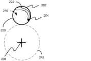
次に、同様の部材に同様の符号を付した図面を参照し、螺旋状バルーン補助装置のさまざまな例及びその使用方法を詳細に開示する。図1は、基本的な構成要素を示す螺旋状バルーン補助装置の図である。螺旋状バルーン補助装置100は、バルーンアセンブリ200、膨張管104、及び膨張ポート106を有している。図2は、バルーンアセンブリ200をより近くで見た図である。バルーンアセンブリは、内側芯部材204によって支持されたバルーン202を有している。バルーン202は、ポリイミドなどの弾性又は半弾性材料で形成することができる。バルーン202は、近位端210から遠位端212まで軸208に沿って軸208を中心として螺旋状に延びている。内側芯部材204は、バルーン202を支持する螺旋状要素である。一実施例では、内側芯部材204はワイヤとすることができる。バルーン202の特定の形状が示されているが、本開示は図に示される形状に限定されない。 Reference will now be made to the drawings, in which like elements are designated by like reference numerals, and various examples of helical balloon assist devices and methods of use thereof will now be disclosed in detail. FIG. 1 is a diagram of a helical balloon assist device showing the basic components. Helical
バルーン202は、軸208と平行に延びる直線部分214を一方又は両方の端部に有することができる。直線部分214は、膨張管104との結合の頑丈さを向上させることができ、カテーテル240上のバルーン202の把持性を高めることができ、又はカテーテル240に沿ったバルーン202の辿りやすさを向上させることができる。また、バルーン202は、純粋に螺旋状であってもよい。バルーン202の螺旋状部分250は、管直径252、バルーン202の各巻きと軸208との間の距離を規定する公称直径254、及びバルーン202の各巻きの間のピッチ256によって記述される。管直径252は、一定であっても変化してもよい。いくつかの例では、管直径252は、バルーン202の端部212に向かってテーパしてもよい。ピッチ256は、一定であってもよく又は変化してもよい。1つの例(図示せず)では、バルーン202は、巻きの一部が螺旋状ではなく、代わりに、螺旋状圧縮ばねの「閉じた」端部と同様、ピッチが0で、軸208に対して垂直な平面に沿ってカテーテルの周囲に巻き付く、「閉じた」端部を有してもよい。
バルーン202は、膨張管104を使用して膨張される。滅菌水、生理食塩水、又は別の適切な溶液を膨張ポート106において膨張管104に導入することができる。膨張ポート106は、当業界で周知のいくつかのタイプのうちの1つであってよい。膨張管104は、バルーン202の内部で終端する開放端218を有している。膨張管104の外周は、その開放端218の近位側の位置においてバルーン202と結合されている。この結合は、螺旋状バルーン補助装置100の使用中の力に耐えうる気密シール及び頑丈な機械的取り付けを与える。
膨張管104は、カテーテル240に沿ったバルーン202の押し込み性を高めるための金属で、可撓性を与えるためのポリイミドなどのポリマー材料で、又は近位端210の金属と、遠位端212に向かって延びるにしたがって移行するポリマー材料との組み合わせで形成することができる。いくつかの例では、膨張管104を使用して螺旋状バルーン補助装置100を遠位方向にカテーテル240に沿って配置し、また、これを近位方向に後退させることができる。いくつかの例では、膨張管104は、内側芯部材204に取り付けられてもよい。他の例では、別のポジショナー(図示せず)をバルーン202及び/又は内側芯部材204に取り付けて螺旋状バルーン補助装置100をカテーテル240に沿って遠位方向に前進させ、また、これを近位方向に後退させるようにすることで、膨張管104の可撓性を高めることができる。ポジショナーは、スプリングテンパーステンレス鋼、又はより好ましくはニチノールのような弾性材料で形成することができる。いくつかの例では、ポジショナーは、ポジショナー、内側本体104、及び/又はバルーン202の材料に応じて適切となりうるように、例えばレーザー又は超音波手段により、接着剤により、圧着によって、又は熱かしめによって取り付けることができる。
バルーンアセンブリ200の長さLは、軸方向に比較的短くてもよい。1つの例では、バルーンアセンブリ200は、カテーテル240の外径Dの2倍以下とすることができる(図6参照)。別の例では、バルーンアセンブリ200は、カテーテル240の外径D以下とすることができる。短い長さLは、バルーンアセンブリ200がバルーンアセンブリをガイドするカテーテル240のより小さな曲率半径の曲がりを辿ることを可能にする。 The length L of
図4A~図4Dは、内側芯部材204の各例を示す。1つの例では、内側芯部材204は、スプリングテンパーステンレス鋼などの弾性材料、又はより好ましくはニチノールなどの超弾性材料で形成される。内側芯部材204は、バルーン202を支持する螺旋状の形状を有している。内側芯部材204はバルーン202に固定されてもよく、又はバルーン202内で固定されなくてもよい。内側芯部材204は、接着剤によって、超音波溶接によって、機械的締結具によって、熱かしめによって、又は当業者には周知の他の手段によって固定されてもよい。バルーン202に固定される場合、内側芯部材204は、バルーン202の内部216、バルーン202の外部、又は図4Cに示されるようにバルーン202の壁220内に固定することができる。内側芯部材204は膨張管104に、接着剤によって、超音波溶接によって、機械的締結具によって、熱かしめによって、又は当業者には周知の他の手段によって固定することもできる。1つの例では、図4Aに示されるように、内側芯部材204は、カテーテル240に最も近いバルーン202の壁220を辿る螺旋状、すなわち、カテーテル240の外径242と同様の公称直径を有する螺旋状に形成することができる。別の例では、内側芯部材204は、図4Bに示されるように、カテーテル240から最も遠いバルーン202の壁220を辿る螺旋状、すなわち、カテーテル240の外径D(円周242によって示される)にバルーン202の管直径の2倍を加えたものにほぼ等しい公称直径を有する螺旋状に形成することができる。 4A-4D illustrate examples of
別の例では、内側芯部材204は、図4Dに示されるように、バルーン202の螺旋形状の内壁220を螺旋状に辿る複数の螺旋222に形成することができる。複数の螺旋222は、バルーンの管直径にほぼ等しい公称直径を有し、バルーン管の中心を辿るスプラインを近似する軸に沿って螺旋状に巻いている。したがって、複数の螺旋222は、カテーテル240の周囲に巻かれた長いコイルばねに似ている。複数の螺旋222は、例えば、機械的に、又は型上で内側芯部材204を熱処理することによって形成されてもよい。 In another example, the
図5~図8は、螺旋状バルーン補助装置100の基本的な動作を示す。図5は、バルーン補助装置がコルク栓抜き状に捻られることによって一時的に変形され、カテーテル上に取り付けられている様子を示す。バルーン202の遠位端212は、バルーン202の最遠位の巻きと最近位の巻きとの間に隙間226が形成されるように変形されている。図6は、近位位置230においてカテーテル上に完全に取り付けられた螺旋状バルーン補助装置を示す。次いで、膨張管104又は別のポジショナー(図示せず)を使用して螺旋状バルーン補助装置100をカテーテル240に沿って摺動させる。図7は、カテーテル240に沿って摺動した後で遠位位置232においてカテーテル240上に取り付けられた螺旋状バルーン補助装置100を示す。次に、図8に示すように、膨張管104を用いてバルーン202を膨張させる。 5-8 illustrate the basic operation of the helical balloon assist
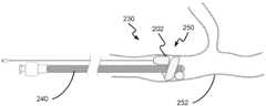
図9~図11は、医療手技の間の螺旋状バルーン補助装置100の基本的な動作を示す。図9は、臨床医によって患者の脈管構造252内の治療部位250に既に配置されていてよいカテーテル240上の近位位置230に完全に取り付けられた螺旋状バルーン補助装置100を示す。次いで、膨張管104又は別のポジショナー(図示せず)を使用して螺旋状バルーン補助装置100をカテーテル240に沿って治療部位250に摺動させる。図10は、治療部位250においてカテーテル240上の遠位位置232に取り付けられた螺旋状バルーン補助装置100を示す。次いで、図11に示されるように、バルーン202を膨張管104を使用して膨張させて、患者の血管構造252の一部を閉塞する。いくつかの例では、螺旋状バルーン補助装置100を臨床手技の間に使用して、血流を閉塞するか、処置によって遊離した組織、血栓、若しくは破片を閉塞又は捕捉するか、又は血管内の定位置にカテーテル240を保持することができる。 9-11 illustrate the basic operation of the helical balloon assist
図12は、螺旋状バルーン補助装置100を使用する各工程を示したフローチャートである。1200において、バルーンの遠位端を変形させて螺旋の巻きの間に隙間226を形成するか又は拡張する。1202において、カテーテル240をバルーン202の巻きの間の隙間226に通して挿入する。1204において、螺旋状バルーン補助装置100をコルク栓抜き状にカテーテル240上に完全に捻る。1206において、膨張管104又はポジショナーを使用して、螺旋状バルーン補助装置100をカテーテル240に沿って患者の脈管構造252内の治療部位250へと摺動させる。いくつかの実施例では、ポジショナーは膨張管104であってよい。1208において、螺旋状バルーン補助装置100を、膨張管104を使用して治療部位250で膨張させる。残りの工程は、臨床手技に応じて任意選択的である。1210において、膨張された螺旋状バルーン補助装置100が治療部位250において血管を閉塞している間に手技を行う。1212において、螺旋状バルーン補助装置100を収縮させる。1214において、収縮した螺旋状バルーン補助装置100を引き抜く。 FIG. 12 is a flowchart showing each step of using the spiral balloon assist
開示される技術の原理と特徴とを理解するのを容易にするために、例示的な実施例を上記で説明してきた。開示される技術のさまざまな要素を構成するものとしてここに説明される構成要素は、例示的なものであって、制限的なものではないことが意図されている。本明細書に説明された構成要素と同じか又は類似の機能を果たす多くの好適な構成要素は、開示される装置及び方法の範囲内に含まれるものとする。本明細書において説明されていない他の構成要素には、例えば、開示される技術の開発後に開発された構成要素が挙げられ得るが、それに限定されない。 Exemplary embodiments have been described above to facilitate an understanding of the principles and features of the disclosed technology. The components described herein as constituting various elements of the disclosed technology are intended to be illustrative and not restrictive. Many suitable components that serve the same or similar functions as those described herein are intended to be included within the scope of the disclosed apparatus and methods. Other components not described herein may include, for example, without limitation, components developed after the development of the disclosed technology.
各例は、螺旋状バルーン補助装置をカテーテル上に取り付けることについて述べているが、螺旋状バルーン補助装置は同様に、ガイドワイヤ、管腔、又は任意の同様に細長い血管外科用器具と共に使用することができる。 Although each example describes mounting the helical balloon assist device on a catheter, the helical balloon assist device may equally be used with a guidewire, lumen, or any similarly elongated vascular surgical instrument. Can be done.
本明細書及び添付の特許請求の範囲において使用される場合、単数形「a」、「an」、及び「the」は、文脈上、そうでないとする明確な指示がない限り、複数の指示対象をも含むことにもまた、留意しなければならない。「備える、含む(comprising)」又は「含有する(containing)」又は「含む(including)」は、少なくとも言及された要素又は方法工程が物品又は方法に存在するが、他の要素又は方法工程の存在を、たとえこれらの他の要素又は方法工程が言及されたものと同じ機能を有するものであっても除外しないことを意味する。 As used in this specification and the appended claims, the singular forms "a," "an," and "the" refer to plural referents unless the context clearly dictates otherwise. It must also be noted that this also includes "Comprising" or "containing" or "including" means that at least the mentioned element or method step is present in the article or method, but the presence of other elements or method steps is not meant to exclude these other elements or method steps even if they have the same function as those mentioned.
また、1つ又は2つ以上の方法工程への言及が、明示的に特定されたそれらの工程間の追加の方法工程又は介在する方法工程の存在を除外しないことも理解されたい。同様に、装置又はシステムの1つ又は2つ以上の構成要素への言及が、明示的に特定された構成要素間の追加の構成要素又は介在する構成要素の存在を排除しないことも理解されたい。 It is also to be understood that reference to one or more method steps does not exclude the presence of additional or intervening method steps between those explicitly identified steps. It is also to be understood that reference to one or more components of a device or system does not exclude the presence of additional or intervening components between the explicitly identified components. .
本出願書において説明される設計及び機能性は、本質的に例示的なものであることが意図され、本開示をいかなる方法でも制限することを意図しない。当事者であれば、本開示の教示は、本明細書において開示される形態及び当業者に知られている追加的形態を含む、さまざまな好適な形態で実施し得るということを理解するであろう。 The designs and functionality described in this application are intended to be exemplary in nature and are not intended to limit the disclosure in any way. Those skilled in the art will appreciate that the teachings of this disclosure may be implemented in a variety of suitable forms, including those disclosed herein and additional forms known to those skilled in the art. .
この技術の特定の例は、フロー図を参照して上記に説明されている。本開示のいくつかの実施例によれば、ブロック図及びフロー図のいくつかのブロックは必ずしも示される順序で実行される必要はなく、又は必ずしも実行される必要はない。 A specific example of this technique is described above with reference to flow diagrams. According to some embodiments of the present disclosure, some blocks of the block diagrams and flow diagrams may not necessarily be executed in the order shown or necessarily executed.
本開示の特定の実施例を、現段階で最も実用的な形態と考えられるもの及びさまざまな実施例と関連させてここまで説明してきたが、本開示は、開示された実施例に限定されず、むしろ、添付の特許請求の範囲に含まれるさまざまな修正例及び均等な構成を含むことが意図されていることを理解すべきである。本明細書において特定の用語が用いられるが、それらは、限定の目的のためではなく、一般的かつ説明的な意味で使用されている。 Although specific embodiments of the disclosure have been described above in what is presently considered the most practical form and in connection with various embodiments, the disclosure is not limited to the disclosed embodiments. On the contrary, it should be understood that the intention is to cover various modifications and equivalent constructions that fall within the scope of the appended claims. Although specific terms are employed herein, they are used in a general and descriptive sense and not for purposes of limitation.
この説明書類は例を用いて、本技術のある特定の実施例を開示し、当業者が、例えば、任意の装置又はシステムを作製し使用すること、及び任意の組み込まれた方法を実行することを含む、本技術のある特定の実施例を実践することを可能にするものである。本技術のある特定の実施例の特許請求可能な範囲は、請求項に定義されるが、当業者が考えつくその他の実施例を含み得る。そのような他の例は、それらが、特許請求の範囲の字義どおりの言語と異ならない構造的要素を有する場合、又はそれらが、特許請求の範囲の字義どおりの言語とごくわずかに異なる均等の構造的要素を含む場合、請求項の範囲内であることが意図される。 This document discloses, by way of example, certain embodiments of the present technology and enables those skilled in the art to, for example, make and use any devices or systems and perform any incorporated methods. , which enables one to practice certain embodiments of the present technology, including: The claimable scope of certain embodiments of the technology is defined in the claims, and may include other embodiments that occur to those skilled in the art. Such other examples are where they have structural elements that do not differ from the literal language of the claims, or where they have equivalents that differ only slightly from the literal language of the claims. Structural elements, if included, are intended to be within the scope of the claims.
〔実施の態様〕
(1) カテーテルに取り付けられて前記カテーテルの位置決めを補助する螺旋状バルーン補助装置であって、前記螺旋状バルーン補助装置は、前記カテーテルの外側に摺動可能に係合するように前記カテーテルに沿って取り付けられており、
非膨張状態で、直線部分と螺旋状部分とを有する管状バルーンと、
前記管状バルーンと密封状態で連通し、前記管状バルーンから近位方向に延びる膨張管と、を備え、
前記管状バルーンの内側に配置され、直線部と螺旋部を備える内側芯部材を更に備え、
前記内側芯部材の前記螺旋部が、前記管状バルーンの壁に沿って螺旋状に延びる複数の螺旋形状に形成され、前記螺旋形状が前記管状バルーンの前記螺旋状部分を支持している、螺旋状バルーン補助装置。
(2)前記内側芯部材が、弾性材料で形成されている、実施態様1に記載の螺旋状バルーン補助装置。
(3) 前記内側芯部材が、前記バルーンに固定されている、実施態様1に記載の螺旋状バルーン補助装置。
(4) 前記内側芯部材が、螺旋軸に最も近いバルーン壁の内側部分に固定されている、実施態様3に記載の螺旋状バルーン補助装置。[Mode of implementation]
(1)A helical balloon auxiliary device attached to a catheter to assist in positioning the catheter, the helical balloon auxiliary device extending along the catheter so as to slidably engage the outside of the catheter. It is installed with
a tubular balloon having a straight portion and a helical portion in an uninflated state;
an inflation tube in sealing communication with the tubular balloon and extending proximally from the tubular balloon;
further comprising an inner core member disposed inside the tubular balloon and having a straight portion and a spiral portion;
the helical portion of the inner core member is formed into a plurality of helical shapes extending helically along a wall of the tubular balloon, the helical shapes supporting the helical portions of the tubular balloon; Balloon auxiliary device.
(2) The helical balloon auxiliary device of embodiment 1, wherein the inner core member is formed of an elastic material.
(3) The helical balloon auxiliary device according to embodiment1 , wherein the inner core member is fixed to the balloon.
(4) The helical balloon assist device of embodiment3 , wherein the inner core member is secured to the inner portion of the balloon wall closest to the helical axis.
(5) 前記内側芯部材が、螺旋軸から最も遠いバルーン壁の内側部分に固定されている、実施態様3に記載の螺旋状バルーン補助装置。
(6) 前記内側芯部材が、接着剤によって、溶接によって、又は機械的締結によってバルーン壁に固定されている、実施態様3に記載の螺旋状バルーン補助装置。
(7) カテーテルに取り付けられて前記カテーテルの位置決めを補助する螺旋状バルーン補助装置であって、前記螺旋状バルーン補助装置は、前記カテーテルの外側に摺動可能に係合するように前記カテーテルに沿って取り付けられており、
非膨張状態で、直線部分と螺旋状部分とを有する管状バルーンと、
前記管状バルーンと密封状態で連通し、前記管状バルーンから近位方向に延びる膨張管と、を備え、
前記管状バルーンの内側に配置され、直線部と螺旋部を備える内側芯部材を更に備え、
前記内側芯部材の前記螺旋部が、前記管状バルーンの壁に沿って螺旋状に延びる複数の螺旋形状に形成され、前記螺旋形状が前記管状バルーンの前記螺旋状部分を支持しており、
前記内側芯部材が、前記管状バルーンに固定されていない、螺旋状バルーン補助装置。
(8) 前記バルーンが弾性材料を含む、実施態様1または7に記載の螺旋状バルーン補助装置。(5) The helical balloon auxiliary device according to embodiment3 , wherein the inner core member is fixed to the inner portion of the balloon wall furthest from the helical axis.
(6) The helical balloon assist device of embodiment3 , wherein the inner core member is secured to the balloon wall by adhesive, by welding, or by mechanical fastening.
(7) A helical balloon auxiliary device attached to a catheter to assist in positioning the catheter, the helical balloon auxiliary device extending along the catheter so as to slidably engage the outside of the catheter. It is installed with
a tubular balloon having a straight portion and a helical portion in an uninflated state;
an inflation tube in sealing communication with the tubular balloon and extending proximally from the tubular balloon;
further comprising an inner core member disposed inside the tubular balloon and having a straight portion and a spiral portion;
the helical portion of the inner core member is formed into a plurality of helical shapes extending helically along the wall of the tubular balloon, the helical shapes supporting the helical portion of the tubular balloon;
A helical balloon accessory, wherein the inner core member is not secured to the tubular balloon .
(8) The helical balloon assist device of embodiment 1or 7 , wherein the balloon comprises an elastic material.
(9) 前記バルーンが非弾性材料を含む、実施態様1または7に記載の螺旋状バルーン補助装置。
(10) カテーテルと、
実施態様1から9のいずれか1つに記載の螺旋状バルーン補助装置であって、
前記管状バルーンと密封状態で連通し、近位方向に延びる前記膨張管と、を備える、螺旋状バルーン補助装置と、を備える、螺旋状バルーン補助カテーテルシステム。(9) The helical balloon assist device of embodiment 1or 7 , wherein the balloon comprises an inelastic material.
(10) A catheter;
A helical balloon auxiliary deviceaccording to any one of embodiments 1 to 9, comprising :
a helical balloon assist catheter system comprising a helical balloon assist device, the inflation tube extending proximally in sealing communication with the tubular balloon.
Claims (10)
Translated fromJapanese非膨張状態で、直線部分と螺旋状部分とを有する管状バルーンと、
前記管状バルーンと密封状態で連通し、前記管状バルーンから近位方向に延びる膨張管と、を備え、
前記管状バルーンの内側に配置され、直線部と螺旋部を備える内側芯部材を更に備え、
前記内側芯部材の前記螺旋部が、前記管状バルーンの壁に沿って螺旋状に延びる複数の螺旋形状に形成され、前記螺旋形状が前記管状バルーンの前記螺旋状部分を支持している、螺旋状バルーン補助装置。 a helical balloon assist device attached to a catheter toassist in positioning thecatheter, the helical balloon assist device being attached along the catheter to slidably engage an exterior of the catheter; and
a tubular balloon having a straight portion and a helical portion in an uninflated state;
an inflation tube in sealing communication with the tubular balloon and extending proximally fromthe tubular balloon ;
further comprising an inner core memberdisposed inside the tubular balloon andhaving a straight portion and a spiral portion;
the helical portion of the inner core member is formed into a plurality of helical shapesextending helically along a wall of the tubular balloon, the helical shapes supporting the helical portions of the tubular balloon ; shaped balloon auxiliary device.
非膨張状態で、直線部分と螺旋状部分とを有する管状バルーンと、
前記管状バルーンと密封状態で連通し、前記管状バルーンから近位方向に延びる膨張管と、を備え、
前記管状バルーンの内側に配置され、直線部と螺旋部を備える内側芯部材を更に備え、
前記内側芯部材の前記螺旋部が、前記管状バルーンの壁に沿って螺旋状に延びる複数の螺旋形状に形成され、前記螺旋形状が前記管状バルーンの前記螺旋状部分を支持しており、
前記内側芯部材が、前記管状バルーンに固定されていない、螺旋状バルーン補助装置。 a helical balloon assist device attached to a catheter toassist in positioning thecatheter, the helical balloon assist device being attached along the catheter to slidably engage an exterior of the catheter; and
a tubular balloon having a straight portion and a helical portion in an uninflated state;
an inflation tube in sealing communication with the tubular balloon and extending proximally fromthe tubular balloon ;
further comprising an inner core memberdisposed inside the tubular balloon andhaving a straight portion and a spiral portion;
the helical portion of the inner core member is formed into a plurality of helical shapes extending helically along the wall of the tubular balloon, the helical shapes supporting the helical portion of the tubular balloon;
A helical balloon accessory, wherein the inner core member is not secured to the tubular balloon.
請求項1から9のいずれか1つに記載の螺旋状バルーン補助装置であって、
前記管状バルーンと密封状態で連通し、近位方向に延びる前記膨張管と、を備える、螺旋状バルーン補助装置と、を備える、螺旋状バルーン補助カテーテルシステム。 catheter and
A helical balloon auxiliary device according to any one ofclaims 1 to 9, comprising:
a helical balloon assist catheter system comprising ahelical balloon assist device, the inflation tube extending proximally in sealing communication with the tubular balloon.
Applications Claiming Priority (2)
| Application Number | Priority Date | Filing Date | Title |
|---|---|---|---|
| US15/941,166 | 2018-03-30 | ||
| US15/941,166US10918390B2 (en) | 2018-03-30 | 2018-03-30 | Helical balloon assist device and method for using the same |
Publications (2)
| Publication Number | Publication Date |
|---|---|
| JP2019181186A JP2019181186A (en) | 2019-10-24 |
| JP7423191B2true JP7423191B2 (en) | 2024-01-29 |
Family
ID=66041283
Family Applications (1)
| Application Number | Title | Priority Date | Filing Date |
|---|---|---|---|
| JP2019066459AActiveJP7423191B2 (en) | 2018-03-30 | 2019-03-29 | Spiral balloon auxiliary device and its usage |
Country Status (6)
| Country | Link |
|---|---|
| US (2) | US10918390B2 (en) |
| EP (1) | EP3546014A1 (en) |
| JP (1) | JP7423191B2 (en) |
| KR (1) | KR20190114879A (en) |
| CN (1) | CN110327537B (en) |
| BR (1) | BR102019006303A2 (en) |
Families Citing this family (1)
| Publication number | Priority date | Publication date | Assignee | Title |
|---|---|---|---|---|
| CN116350918A (en)* | 2023-02-24 | 2023-06-30 | 广东博迈医疗科技股份有限公司 | A balloon catheter for the treatment of myocardial infarction |
Citations (6)
| Publication number | Priority date | Publication date | Assignee | Title |
|---|---|---|---|---|
| JP2001009045A (en) | 1999-06-30 | 2001-01-16 | Kanegafuchi Chem Ind Co Ltd | Catheter system for centering |
| WO2002102451A1 (en) | 2001-06-19 | 2002-12-27 | Medtronic Ave, Inc. | Intraluminal therapy catheter with inflatable helical member and methods of use |
| US20060074437A1 (en) | 2004-10-06 | 2006-04-06 | Scimed Life Systems, Inc. | Medical retrieval device |
| JP2013223663A (en) | 2012-04-23 | 2013-10-31 | Terumo Corp | Protective sleeve for balloon catheter, balloon catheter system, and stent delivery system |
| JP2014508574A (en) | 2011-01-17 | 2014-04-10 | ノビタ・セラピューティクス・リミテッド・ライアビリティ・カンパニー | Detachable metal balloon delivery device and method |
| JP2016501679A (en) | 2012-12-28 | 2016-01-21 | バード・ペリフェラル・バスキュラー・インコーポレーテッド | Drug transfer via mechanical vibrating balloon |
Family Cites Families (176)
| Publication number | Priority date | Publication date | Assignee | Title |
|---|---|---|---|---|
| US3811448A (en)* | 1972-10-25 | 1974-05-21 | A Morton | Urinary drainage catheter |
| US4762130A (en)* | 1987-01-15 | 1988-08-09 | Thomas J. Fogarty | Catheter with corkscrew-like balloon |
| DE4018525C2 (en) | 1990-06-09 | 1994-05-05 | Kaltenbach Martin | Expandable area catheter |
| US5295958A (en)* | 1991-04-04 | 1994-03-22 | Shturman Cardiology Systems, Inc. | Method and apparatus for in vivo heart valve decalcification |
| US5181911A (en)* | 1991-04-22 | 1993-01-26 | Shturman Technologies, Inc. | Helical balloon perfusion angioplasty catheter |
| CA2074304C (en)* | 1991-08-02 | 1996-11-26 | Cyril J. Schweich, Jr. | Drug delivery catheter |
| US5226888A (en)* | 1991-10-25 | 1993-07-13 | Michelle Arney | Coiled, perfusion balloon catheter |
| DK171747B1 (en)* | 1993-03-02 | 1997-05-05 | Metra Aps | dilatation catheter |
| US5985307A (en) | 1993-04-14 | 1999-11-16 | Emory University | Device and method for non-occlusive localized drug delivery |
| US6196996B1 (en)* | 1993-07-15 | 2001-03-06 | Paul S. Teirstein | Irradiation catheter and method of use |
| US5549555A (en) | 1995-02-22 | 1996-08-27 | Influence, Inc. | Balloon catheter |
| US5882334A (en) | 1995-12-04 | 1999-03-16 | Target Therapeutics, Inc. | Balloon/delivery catheter assembly with adjustable balloon positioning |
| US5855546A (en) | 1996-02-29 | 1999-01-05 | Sci-Med Life Systems | Perfusion balloon and radioactive wire delivery system |
| US6544276B1 (en) | 1996-05-20 | 2003-04-08 | Medtronic Ave. Inc. | Exchange method for emboli containment |
| US5797948A (en)* | 1996-10-03 | 1998-08-25 | Cordis Corporation | Centering balloon catheter |
| US5843027A (en) | 1996-12-04 | 1998-12-01 | Cardiovascular Dynamics, Inc. | Balloon sheath |
| US5919163A (en) | 1997-07-14 | 1999-07-06 | Delcath Systems, Inc. | Catheter with slidable balloon |
| US6610083B2 (en)* | 1998-08-24 | 2003-08-26 | Radiant Medical, Inc. | Multiple lumen heat exchange catheters |
| US6575932B1 (en) | 1999-12-02 | 2003-06-10 | Ottawa Heart Institute | Adjustable multi-balloon local delivery device |
| US6391037B1 (en) | 2000-03-02 | 2002-05-21 | Prodesco, Inc. | Bag for use in the intravascular treatment of saccular aneurysms |
| US6409652B1 (en)* | 2000-09-20 | 2002-06-25 | Vascular Architects, Inc. | Device and method for delivery of uniform and controlled radiation dose to blood vessels |
| US6666828B2 (en) | 2001-06-29 | 2003-12-23 | Medtronic, Inc. | Catheter system having disposable balloon |
| US8252040B2 (en) | 2001-07-20 | 2012-08-28 | Microvention, Inc. | Aneurysm treatment device and method of use |
| US8715312B2 (en) | 2001-07-20 | 2014-05-06 | Microvention, Inc. | Aneurysm treatment device and method of use |
| US7300415B2 (en) | 2002-12-20 | 2007-11-27 | Advanced Cardiovascular Systems, Inc. | Balloon catheter having an external guidewire |
| US6923808B2 (en)* | 2003-02-24 | 2005-08-02 | Boston Scientific Scimed, Inc. | Probes having helical and loop shaped inflatable therapeutic elements |
| US20040176790A1 (en) | 2003-03-03 | 2004-09-09 | Medtronic Ave, Inc. | Single lumen catheter shaft for a balloon catheter |
| US7371228B2 (en) | 2003-09-19 | 2008-05-13 | Medtronic Vascular, Inc. | Delivery of therapeutics to treat aneurysms |
| US7435248B2 (en)* | 2003-09-26 | 2008-10-14 | Boston Scientific Scimed, Inc. | Medical probes for creating and diagnosing circumferential lesions within or around the ostium of a vessel |
| US7695508B2 (en) | 2003-10-16 | 2010-04-13 | Minvasys Sa | Catheter system for stenting bifurcated vessels |
| US7468051B2 (en)* | 2004-03-02 | 2008-12-23 | Boston Scientific Scimed, Inc. | Occlusion balloon catheter with external inflation lumen |
| US9308382B2 (en) | 2004-06-10 | 2016-04-12 | Medtronic Urinary Solutions, Inc. | Implantable pulse generator systems and methods for providing functional and/or therapeutic stimulation of muscles and/or nerves and/or central nervous system tissue |
| US9655633B2 (en) | 2004-09-10 | 2017-05-23 | Penumbra, Inc. | System and method for treating ischemic stroke |
| WO2006052322A2 (en) | 2004-09-22 | 2006-05-18 | Guterman Lee R | Cranial aneurysm treatment arrangement |
| US20060089637A1 (en) | 2004-10-14 | 2006-04-27 | Werneth Randell L | Ablation catheter |
| US8562672B2 (en) | 2004-11-19 | 2013-10-22 | Medtronic, Inc. | Apparatus for treatment of cardiac valves and method of its manufacture |
| WO2006094243A1 (en)* | 2005-03-02 | 2006-09-08 | C.R. Bard, Inc. | Expandable access sheath |
| US9636115B2 (en) | 2005-06-14 | 2017-05-02 | Stryker Corporation | Vaso-occlusive delivery device with kink resistant, flexible distal end |
| US20060287666A1 (en)* | 2005-06-15 | 2006-12-21 | Usgi Medical Inc. | Apparatus and methods for endoluminal advancement |
| EP2759276A1 (en) | 2005-06-20 | 2014-07-30 | Medtronic Ablation Frontiers LLC | Ablation catheter |
| US8066036B2 (en) | 2005-11-17 | 2011-11-29 | Microvention, Inc. | Three-dimensional complex coil |
| US20070185444A1 (en) | 2006-02-03 | 2007-08-09 | Starfire Medical, Inc. | Vascular clip-on occlusion system |
| US9757260B2 (en) | 2006-03-30 | 2017-09-12 | Medtronic Vascular, Inc. | Prosthesis with guide lumen |
| US9615832B2 (en) | 2006-04-07 | 2017-04-11 | Penumbra, Inc. | Aneurysm occlusion system and method |
| CA2655026C (en) | 2006-06-15 | 2016-08-02 | Microvention, Inc. | Embolization device constructed from expansible polymer |
| US20080281350A1 (en) | 2006-12-13 | 2008-11-13 | Biomerix Corporation | Aneurysm Occlusion Devices |
| EP2134405B1 (en) | 2007-03-27 | 2021-06-02 | Intratech Medical Ltd. | Spiral balloon catheter |
| US8075519B2 (en)* | 2007-12-06 | 2011-12-13 | Abbott Cardiovascular Systems Inc. | Agent delivery catheter having a radially expandable centering support members |
| WO2009086208A2 (en) | 2007-12-21 | 2009-07-09 | Microvention, Inc. | Hydrogel filaments for biomedical uses |
| US8974518B2 (en) | 2008-03-25 | 2015-03-10 | Medtronic Vascular, Inc. | Eversible branch stent-graft and deployment method |
| EP2192947A1 (en) | 2008-04-30 | 2010-06-09 | Medtronic, Inc. | Techniques for placing medical leads for electrical stimulation of nerve tissue |
| US8070694B2 (en) | 2008-07-14 | 2011-12-06 | Medtronic Vascular, Inc. | Fiber based medical devices and aspiration catheters |
| US8333796B2 (en) | 2008-07-15 | 2012-12-18 | Penumbra, Inc. | Embolic coil implant system and implantation method |
| US9232992B2 (en) | 2008-07-24 | 2016-01-12 | Aga Medical Corporation | Multi-layered medical device for treating a target site and associated method |
| US8721714B2 (en) | 2008-09-17 | 2014-05-13 | Medtronic Corevalve Llc | Delivery system for deployment of medical devices |
| US9717500B2 (en) | 2009-04-15 | 2017-08-01 | Microvention, Inc. | Implant delivery system |
| US8758423B2 (en) | 2009-06-18 | 2014-06-24 | Graftcraft I Goteborg Ab | Device and method for treating ruptured aneurysms |
| US8911487B2 (en) | 2009-09-22 | 2014-12-16 | Penumbra, Inc. | Manual actuation system for deployment of implant |
| US20110137331A1 (en) | 2009-12-07 | 2011-06-09 | Michael Walsh | Perfusion device |
| CA2784499C (en)* | 2009-12-15 | 2017-04-18 | Edwards Lifesciences Corporation | Expansion device for treatment of vascular passageways |
| AU2011240927B2 (en) | 2010-04-14 | 2015-07-16 | Microvention, Inc. | Implant delivery device |
| US8764811B2 (en) | 2010-04-20 | 2014-07-01 | Medtronic Vascular, Inc. | Controlled tip release stent graft delivery system and method |
| JP4846044B1 (en) | 2010-06-30 | 2011-12-28 | テルモ株式会社 | Medical device |
| US8876878B2 (en) | 2010-07-23 | 2014-11-04 | Medtronic, Inc. | Attachment mechanism for stent release |
| US9084609B2 (en)* | 2010-07-30 | 2015-07-21 | Boston Scientific Scime, Inc. | Spiral balloon catheter for renal nerve ablation |
| CN101919737B (en) | 2010-08-03 | 2012-07-11 | 安瑞医疗器械(杭州)有限公司 | A medical device for interventional diagnosis and treatment of gallbladder disease |
| US8616040B2 (en) | 2010-09-17 | 2013-12-31 | Medtronic Vascular, Inc. | Method of forming a drug-eluting medical device |
| WO2012088162A1 (en) | 2010-12-20 | 2012-06-28 | Microvention, Inc. | Polymer stents and methods of manufacture |
| US9480823B2 (en)* | 2011-03-04 | 2016-11-01 | Medtronic Vascular, Inc. | Perfusion dilation catheter system and methods of use |
| US8486014B2 (en)* | 2011-03-26 | 2013-07-16 | Medtronic Vascular, Inc. | Spiral perfusion dilatation balloon for use in valvuloplasty procedure |
| US20120283768A1 (en) | 2011-05-05 | 2012-11-08 | Sequent Medical Inc. | Method and apparatus for the treatment of large and giant vascular defects |
| US9486604B2 (en) | 2011-05-12 | 2016-11-08 | Medtronic, Inc. | Packaging and preparation tray for a delivery system |
| WO2012158668A1 (en) | 2011-05-17 | 2012-11-22 | Stryker Corporation | Method of fabricating an implantable medical device that includes one or more thin film polymer support layers |
| WO2012166467A1 (en) | 2011-05-27 | 2012-12-06 | Stryker Corporation | Assembly for percutaneously inserting an implantable medical device, steering the device to a target location and deploying the device |
| US9750565B2 (en) | 2011-09-30 | 2017-09-05 | Medtronic Advanced Energy Llc | Electrosurgical balloons |
| CA2867181C (en) | 2012-03-16 | 2020-08-11 | Microvention, Inc. | Stent and stent delivery device |
| US9717421B2 (en) | 2012-03-26 | 2017-08-01 | Medtronic, Inc. | Implantable medical device delivery catheter with tether |
| US9833625B2 (en) | 2012-03-26 | 2017-12-05 | Medtronic, Inc. | Implantable medical device delivery with inner and outer sheaths |
| US9242290B2 (en) | 2012-04-03 | 2016-01-26 | Medtronic Vascular, Inc. | Method and apparatus for creating formed elements used to make wound stents |
| US9700399B2 (en) | 2012-04-26 | 2017-07-11 | Medtronic Vascular, Inc. | Stopper to prevent graft material slippage in a closed web stent-graft |
| US9549832B2 (en) | 2012-04-26 | 2017-01-24 | Medtronic Vascular, Inc. | Apparatus and methods for filling a drug eluting medical device via capillary action |
| US9149190B2 (en) | 2012-07-17 | 2015-10-06 | Stryker Corporation | Notification system of deviation from predefined conditions |
| EP2882350B1 (en) | 2012-08-13 | 2019-09-25 | MicroVention, Inc. | Shaped removal device |
| WO2014036160A2 (en)* | 2012-08-28 | 2014-03-06 | Boston Scientific Scimed, Inc. | Renal nerve modulation and ablation catheter electrode design |
| EP2895228B1 (en) | 2012-09-11 | 2019-11-20 | Boston Scientific Scimed, Inc. | Loading tools for use with balloon catheters |
| EP2903569B1 (en)* | 2012-10-01 | 2020-12-16 | QMax, LLC | Helical balloon catheter |
| US9504476B2 (en) | 2012-10-01 | 2016-11-29 | Microvention, Inc. | Catheter markers |
| EP2906254B1 (en) | 2012-10-15 | 2020-01-08 | Microvention, Inc. | Polymeric treatment compositions |
| US10327781B2 (en) | 2012-11-13 | 2019-06-25 | Covidien Lp | Occlusive devices |
| EP2730309A1 (en)* | 2012-11-13 | 2014-05-14 | Biotronik AG | Balloon catheter for curved vessels |
| US9180033B2 (en) | 2012-11-20 | 2015-11-10 | Indiana University Research And Technology Corp. | Intravascular shunt for traumatized arteries |
| US9539022B2 (en) | 2012-11-28 | 2017-01-10 | Microvention, Inc. | Matter conveyance system |
| WO2014089392A1 (en) | 2012-12-07 | 2014-06-12 | Medtronic, Inc. | Minimally invasive implantable neurostimulation system |
| US10342546B2 (en) | 2013-01-14 | 2019-07-09 | Microvention, Inc. | Occlusive device |
| US9539382B2 (en) | 2013-03-12 | 2017-01-10 | Medtronic, Inc. | Stepped catheters with flow restrictors and infusion systems using the same |
| WO2014150824A1 (en) | 2013-03-14 | 2014-09-25 | Stryker Corporation | Vaso-occlusive device delivery system |
| CN105228534B (en) | 2013-03-14 | 2018-03-30 | 斯瑞克公司 | Vaso-Occlusive Device Delivery System |
| EP2967573B1 (en) | 2013-03-14 | 2021-04-21 | Stryker Corporation | Vaso-occlusive device delivery system |
| BR112015023602A2 (en) | 2013-03-15 | 2017-07-18 | Microvention Inc | embolic protection device |
| WO2014151123A1 (en) | 2013-03-15 | 2014-09-25 | Microvention, Inc. | Multi-component obstruction removal system and method |
| US9398966B2 (en) | 2013-03-15 | 2016-07-26 | Medtronic Vascular, Inc. | Welded stent and stent delivery system |
| US9345864B2 (en) | 2013-03-15 | 2016-05-24 | Terumo Kabushiki Kaisha | Methods for treating sinus ostia using balloon catheter devices having a slidable balloon portion |
| US9662425B2 (en) | 2013-04-22 | 2017-05-30 | Stryker European Holdings I, Llc | Method for drug loading hydroxyapatite coated implant surfaces |
| CA3142074A1 (en)* | 2013-05-02 | 2014-11-06 | Veryan Medical Limited | Expandable balloon |
| US20140343409A1 (en) | 2013-05-17 | 2014-11-20 | Ninepoint Medical, Inc. | Inflation apparatus with pressure relief, related systems, methods and kits |
| US9445928B2 (en) | 2013-05-30 | 2016-09-20 | Medtronic Vascular, Inc. | Delivery system having a single handed deployment handle for a retractable outer sheath |
| CA3199859A1 (en)* | 2013-08-12 | 2015-02-19 | Mitral Valve Technologies Sarl | Apparatus and methods for implanting a replacement heart valve |
| US9675782B2 (en) | 2013-10-10 | 2017-06-13 | Medtronic Vascular, Inc. | Catheter pull wire actuation mechanism |
| US9955978B2 (en) | 2013-10-25 | 2018-05-01 | Medtronic Vascular, Inc. | Tissue compression device with multi-chamber bladder |
| WO2015061801A2 (en) | 2013-10-26 | 2015-04-30 | Accumed Radial Systems Llc | System, apparatus, and method for creating a lumen |
| EP3082939B1 (en) | 2013-12-20 | 2020-12-02 | MicroVention, Inc. | Delivery adapter |
| KR102211335B1 (en) | 2013-12-20 | 2021-02-03 | 마이크로벤션, 인코포레이티드 | Device delivery system |
| US20150238729A1 (en)* | 2014-02-24 | 2015-08-27 | Mark Lynn Jenson | Cardiac Access Catheter, System, and Method |
| US10213208B2 (en) | 2014-03-24 | 2019-02-26 | J. Mathieu Massicotte | Toroidal balloon for external or internal compression with unique insertion or removal |
| JP6488552B2 (en) | 2014-03-31 | 2019-03-27 | 日本ゼオン株式会社 | Tube stent delivery device |
| WO2015157181A1 (en) | 2014-04-08 | 2015-10-15 | Stryker Corporation | Implant delivery system |
| WO2015167997A1 (en) | 2014-04-30 | 2015-11-05 | Stryker Corporation | Implant delivery system and method of use |
| US9060777B1 (en) | 2014-05-28 | 2015-06-23 | Tw Medical Technologies, Llc | Vaso-occlusive devices and methods of use |
| US9668898B2 (en) | 2014-07-24 | 2017-06-06 | Medtronic Vascular, Inc. | Stent delivery system having dynamic deployment and methods of manufacturing same |
| US9770577B2 (en) | 2014-09-15 | 2017-09-26 | Medtronic Xomed, Inc. | Pressure relief for a catheter balloon device |
| US9579484B2 (en) | 2014-09-19 | 2017-02-28 | Medtronic Vascular, Inc. | Sterile molded dispenser |
| US9692557B2 (en) | 2015-02-04 | 2017-06-27 | Stryker European Holdings I, Llc | Apparatus and methods for administering treatment within a bodily duct of a patient |
| CN107072491B (en) | 2015-03-19 | 2019-08-13 | 奥林巴斯株式会社 | Plug-in part installation equipment of plug-in equipment, plug-in system |
| EP3274036B1 (en) | 2015-03-25 | 2020-02-19 | Rigshospitalet, Copenhagen University Hospital | Balloon-tipped catheter for continuous nerve blocks |
| US10086213B2 (en) | 2015-04-23 | 2018-10-02 | Mark A. D'Andrea | Mobile gynecological balloon devices and methods |
| US10307168B2 (en) | 2015-08-07 | 2019-06-04 | Terumo Corporation | Complex coil and manufacturing techniques |
| US10154905B2 (en) | 2015-08-07 | 2018-12-18 | Medtronic Vascular, Inc. | System and method for deflecting a delivery catheter |
| US10492938B2 (en) | 2015-08-11 | 2019-12-03 | Terumo Corporation | System and method for implant delivery |
| JP6816126B2 (en) | 2015-09-18 | 2021-01-20 | マイクロベンション インコーポレイテッドMicrovention, Inc. | Releasable delivery system |
| EP3349669B1 (en) | 2015-09-18 | 2020-10-21 | Terumo Corporation | Vessel prosthesis |
| CN113952095B (en) | 2015-09-18 | 2025-06-06 | 微仙美国有限公司 | Implant retention, detachment and delivery systems |
| JP6854282B2 (en) | 2015-09-18 | 2021-04-07 | テルモ株式会社 | Pressable implant delivery system |
| CN108024821B (en) | 2015-09-21 | 2020-10-30 | 斯瑞克公司 | Embolectomy device |
| JP6591664B2 (en) | 2015-09-21 | 2019-10-16 | ストライカー コーポレイションStryker Corporation | Embolization removal device |
| US10172632B2 (en) | 2015-09-22 | 2019-01-08 | Medtronic Vascular, Inc. | Occlusion bypassing apparatus with a re-entry needle and a stabilization tube |
| US10327791B2 (en) | 2015-10-07 | 2019-06-25 | Medtronic Vascular, Inc. | Occlusion bypassing apparatus with a re-entry needle and a distal stabilization balloon |
| WO2017062383A1 (en) | 2015-10-07 | 2017-04-13 | Stryker Corporation | Multiple barrel clot removal devices |
| US10786302B2 (en) | 2015-10-09 | 2020-09-29 | Medtronic, Inc. | Method for closure and ablation of atrial appendage |
| US10105519B2 (en) | 2015-10-20 | 2018-10-23 | C.R. Bard, Inc. | Variable diameter medical balloon |
| US10271873B2 (en) | 2015-10-26 | 2019-04-30 | Medtronic Vascular, Inc. | Sheathless guide catheter assembly |
| JP6937313B2 (en)* | 2015-11-09 | 2021-09-22 | リヴァンプ メディカル リミテッド | Blood flow reducer for cardiovascular treatment |
| WO2017087816A1 (en) | 2015-11-19 | 2017-05-26 | Penumbra, Inc. | Systems and methods for treatment of stroke |
| US10631946B2 (en) | 2015-11-30 | 2020-04-28 | Penumbra, Inc. | System for endoscopic intracranial procedures |
| EP3386580B1 (en) | 2015-12-09 | 2023-11-01 | Medtronic Vascular Inc. | Catheter with a lumen shaped as an identification symbol |
| US10159568B2 (en) | 2015-12-14 | 2018-12-25 | Medtronic, Inc. | Delivery system having retractable wires as a coupling mechanism and a deployment mechanism for a self-expanding prosthesis |
| US10500046B2 (en) | 2015-12-14 | 2019-12-10 | Medtronic, Inc. | Delivery system having retractable wires as a coupling mechanism and a deployment mechanism for a self-expanding prosthesis |
| WO2017117284A1 (en) | 2015-12-30 | 2017-07-06 | Stryker Corporation | Embolic devices and methods of manufacturing same |
| US20170189033A1 (en) | 2016-01-06 | 2017-07-06 | Microvention, Inc. | Occlusive Embolic Coil |
| US10070950B2 (en) | 2016-02-09 | 2018-09-11 | Medtronic Vascular, Inc. | Endoluminal prosthetic assemblies, and associated systems and methods for percutaneous repair of a vascular tissue defect |
| AU2017218115B2 (en) | 2016-02-10 | 2020-03-05 | Microvention, Inc. | Devices for vascular occlusion |
| KR102837372B1 (en) | 2016-02-10 | 2025-07-24 | 마이크로벤션, 인코포레이티드 | Intravascular treatment site access |
| US10188500B2 (en) | 2016-02-12 | 2019-01-29 | Medtronic Vascular, Inc. | Stent graft with external scaffolding and method |
| CN205434660U (en) | 2016-02-18 | 2016-08-10 | 仇汉诚 | Balloon catheter |
| US20170281331A1 (en) | 2016-03-31 | 2017-10-05 | Medtronic Vascular, Inc. | Endoluminal prosthetic devices having fluid-absorbable compositions for repair of a vascular tissue defect |
| CN114432008A (en) | 2016-03-31 | 2022-05-06 | 美敦力瓦斯科尔勒公司 | Expandable introducer sheath with steering mechanism |
| US10695542B2 (en) | 2016-04-04 | 2020-06-30 | Medtronic Vascular, Inc. | Drug coated balloon |
| US10252024B2 (en) | 2016-04-05 | 2019-04-09 | Stryker Corporation | Medical devices and methods of manufacturing same |
| US10441407B2 (en) | 2016-04-12 | 2019-10-15 | Medtronic Vascular, Inc. | Gutter filling stent-graft and method |
| US9987122B2 (en) | 2016-04-13 | 2018-06-05 | Medtronic Vascular, Inc. | Iliac branch device and method |
| US10010403B2 (en) | 2016-04-18 | 2018-07-03 | Medtronic Vascular, Inc. | Stent-graft prosthesis and method of manufacture |
| US20170304097A1 (en) | 2016-04-21 | 2017-10-26 | Medtronic Vascular, Inc. | Stent-graft delivery system having an inner shaft component with a loading pad or covering on a distal segment thereof for stent retention |
| US10517711B2 (en) | 2016-04-25 | 2019-12-31 | Medtronic Vascular, Inc. | Dissection prosthesis system and method |
| WO2017189591A1 (en) | 2016-04-25 | 2017-11-02 | Stryker Corporation | Inverting mechanical thrombectomy apparatuses and methods of use in the vasculature |
| US10940294B2 (en) | 2016-04-25 | 2021-03-09 | Medtronic Vascular, Inc. | Balloon catheter including a drug delivery sheath |
| EP3590446B1 (en) | 2016-04-25 | 2021-01-06 | Stryker Corporation | Anti-jamming and macerating thrombectomy apparatuses |
| EP3448276B1 (en) | 2016-04-25 | 2020-03-04 | Stryker Corporation | Clot-engulfing mechanical thrombectomy apparatuses |
| US11147952B2 (en) | 2016-04-28 | 2021-10-19 | Medtronic Vascular, Inc. | Drug coated inflatable balloon having a thermal dependent release layer |
| US10191615B2 (en) | 2016-04-28 | 2019-01-29 | Medtronic Navigation, Inc. | Method and apparatus for image-based navigation |
| US10406011B2 (en) | 2016-04-28 | 2019-09-10 | Medtronic Vascular, Inc. | Implantable medical device delivery system |
| US10292844B2 (en) | 2016-05-17 | 2019-05-21 | Medtronic Vascular, Inc. | Method for compressing a stented prosthesis |
| US10786659B2 (en) | 2016-06-01 | 2020-09-29 | Microvention, Inc. | Reinforced balloon catheter |
| CN109561903B (en) | 2016-06-03 | 2021-07-27 | 斯瑞克公司 | Flip thrombectomy device |
| CN110603005A (en)* | 2016-09-28 | 2019-12-20 | 项目莫里股份有限公司 | Delivery methods and devices for arrhythmia diagnosis and/or treatment, and robotic systems for other uses |
| CN107468295B (en) | 2017-09-06 | 2024-05-07 | 何冀芳 | Working saccule catheter/microcatheter stress application support system and intervention conduction system |
| US10786259B2 (en)* | 2018-03-30 | 2020-09-29 | DePuy Synthes Products, Inc. | Split balloon assist device and method for using the same |
| US20210138211A1 (en)* | 2019-11-07 | 2021-05-13 | Project Moray, Inc. | Asymmetric Articulation For Catheter Systems and Other Uses |
- 2018
- 2018-03-30USUS15/941,166patent/US10918390B2/enactiveActive
- 2019
- 2019-03-28BRBR102019006303-3Apatent/BR102019006303A2/ennot_activeApplication Discontinuation
- 2019-03-29EPEP19166286.5Apatent/EP3546014A1/ennot_activeWithdrawn
- 2019-03-29CNCN201910251269.XApatent/CN110327537B/enactiveActive
- 2019-03-29JPJP2019066459Apatent/JP7423191B2/enactiveActive
- 2019-03-29KRKR1020190036577Apatent/KR20190114879A/ennot_activeWithdrawn
- 2021
- 2021-01-14USUS17/148,867patent/US11819214B2/enactiveActive
Patent Citations (7)
| Publication number | Priority date | Publication date | Assignee | Title |
|---|---|---|---|---|
| JP2001009045A (en) | 1999-06-30 | 2001-01-16 | Kanegafuchi Chem Ind Co Ltd | Catheter system for centering |
| WO2002102451A1 (en) | 2001-06-19 | 2002-12-27 | Medtronic Ave, Inc. | Intraluminal therapy catheter with inflatable helical member and methods of use |
| JP2004529741A (en) | 2001-06-19 | 2004-09-30 | メドトロニック ヴァスキュラー インコーポレイテッド | Endoluminal treatment catheter with inflatable helical member |
| US20060074437A1 (en) | 2004-10-06 | 2006-04-06 | Scimed Life Systems, Inc. | Medical retrieval device |
| JP2014508574A (en) | 2011-01-17 | 2014-04-10 | ノビタ・セラピューティクス・リミテッド・ライアビリティ・カンパニー | Detachable metal balloon delivery device and method |
| JP2013223663A (en) | 2012-04-23 | 2013-10-31 | Terumo Corp | Protective sleeve for balloon catheter, balloon catheter system, and stent delivery system |
| JP2016501679A (en) | 2012-12-28 | 2016-01-21 | バード・ペリフェラル・バスキュラー・インコーポレーテッド | Drug transfer via mechanical vibrating balloon |
Also Published As
| Publication number | Publication date |
|---|---|
| BR102019006303A2 (en) | 2019-10-01 |
| JP2019181186A (en) | 2019-10-24 |
| KR20190114879A (en) | 2019-10-10 |
| US10918390B2 (en) | 2021-02-16 |
| CN110327537B (en) | 2023-03-10 |
| CN110327537A (en) | 2019-10-15 |
| US20210128164A1 (en) | 2021-05-06 |
| US11819214B2 (en) | 2023-11-21 |
| US20190298384A1 (en) | 2019-10-03 |
| EP3546014A1 (en) | 2019-10-02 |
Similar Documents
| Publication | Publication Date | Title |
|---|---|---|
| CN215651393U (en) | Medical catheter and medical device | |
| CN109862835B (en) | Clot retrieval system for removing an occluded clot from a blood vessel | |
| JP7330984B2 (en) | Balloon catheter assisted by pulling a pull wire | |
| US20070276426A1 (en) | Steerable balloon catheters and methods | |
| EP1984061B1 (en) | Coaxial PTA balloon | |
| US7476232B2 (en) | Access catheter having dilation capability and related methods | |
| US6780199B2 (en) | Enhanced stent delivery system | |
| US20070167972A1 (en) | Balloon apparatus and methods | |
| JP7309413B2 (en) | Segmented balloon assist device and method of use thereof | |
| US20070276427A1 (en) | Torquable balloon catheters and methods | |
| JPH0626576B2 (en) | Device for performing angiogenesis | |
| WO2008079810A2 (en) | Hemostasis-enhancing device and method for its use | |
| JP2002515308A (en) | Enhanced balloon expansion system | |
| US20120158033A1 (en) | Expandable sheath | |
| JP3533299B2 (en) | Nickel-titanium slip medical catheter wire | |
| JP7423191B2 (en) | Spiral balloon auxiliary device and its usage | |
| JP7366565B2 (en) | Balloon support device and method for using it | |
| JP2512790Y2 (en) | Medical balloon catheter | |
| WO2011146085A1 (en) | Rapid response balloon catheter |
Legal Events
| Date | Code | Title | Description |
|---|---|---|---|
| A621 | Written request for application examination | Free format text:JAPANESE INTERMEDIATE CODE: A621 Effective date:20220329 | |
| A977 | Report on retrieval | Free format text:JAPANESE INTERMEDIATE CODE: A971007 Effective date:20230210 | |
| A131 | Notification of reasons for refusal | Free format text:JAPANESE INTERMEDIATE CODE: A131 Effective date:20230314 | |
| A521 | Request for written amendment filed | Free format text:JAPANESE INTERMEDIATE CODE: A523 Effective date:20230613 | |
| A131 | Notification of reasons for refusal | Free format text:JAPANESE INTERMEDIATE CODE: A131 Effective date:20230711 | |
| A601 | Written request for extension of time | Free format text:JAPANESE INTERMEDIATE CODE: A601 Effective date:20231011 | |
| A521 | Request for written amendment filed | Free format text:JAPANESE INTERMEDIATE CODE: A523 Effective date:20231208 | |
| TRDD | Decision of grant or rejection written | ||
| A01 | Written decision to grant a patent or to grant a registration (utility model) | Free format text:JAPANESE INTERMEDIATE CODE: A01 Effective date:20231226 | |
| A61 | First payment of annual fees (during grant procedure) | Free format text:JAPANESE INTERMEDIATE CODE: A61 Effective date:20240117 | |
| R150 | Certificate of patent or registration of utility model | Ref document number:7423191 Country of ref document:JP Free format text:JAPANESE INTERMEDIATE CODE: R150 |