JP7421060B2 - vehicle seat - Google Patents
vehicle seatDownload PDFInfo
- Publication number
- JP7421060B2 JP7421060B2JP2019132011AJP2019132011AJP7421060B2JP 7421060 B2JP7421060 B2JP 7421060B2JP 2019132011 AJP2019132011 AJP 2019132011AJP 2019132011 AJP2019132011 AJP 2019132011AJP 7421060 B2JP7421060 B2JP 7421060B2
- Authority
- JP
- Japan
- Prior art keywords
- seat
- vehicle seat
- detection sensor
- load detection
- link
- Prior art date
- Legal status (The legal status is an assumption and is not a legal conclusion. Google has not performed a legal analysis and makes no representation as to the accuracy of the status listed.)
- Active
Links
- 238000001514detection methodMethods0.000claimsdescription110
- 230000007246mechanismEffects0.000claimsdescription33
- 239000000463materialSubstances0.000claimsdescription5
- 239000011347resinSubstances0.000description5
- 229920005989resinPolymers0.000description5
- 239000002184metalSubstances0.000description4
- 239000000758substrateSubstances0.000description2
- 238000003466weldingMethods0.000description2
- JOYRKODLDBILNP-UHFFFAOYSA-NEthyl urethaneChemical compoundCCOC(N)=OJOYRKODLDBILNP-UHFFFAOYSA-N0.000description1
- 229910000831SteelInorganic materials0.000description1
- 230000004048modificationEffects0.000description1
- 238000012986modificationMethods0.000description1
- 230000001105regulatory effectEffects0.000description1
- 239000010959steelSubstances0.000description1
Images


Classifications
- B—PERFORMING OPERATIONS; TRANSPORTING
- B60—VEHICLES IN GENERAL
- B60N—SEATS SPECIALLY ADAPTED FOR VEHICLES; VEHICLE PASSENGER ACCOMMODATION NOT OTHERWISE PROVIDED FOR
- B60N2/00—Seats specially adapted for vehicles; Arrangement or mounting of seats in vehicles
- B60N2/02—Seats specially adapted for vehicles; Arrangement or mounting of seats in vehicles the seat or part thereof being movable, e.g. adjustable
- B60N2/04—Seats specially adapted for vehicles; Arrangement or mounting of seats in vehicles the seat or part thereof being movable, e.g. adjustable the whole seat being movable
- B60N2/16—Seats specially adapted for vehicles; Arrangement or mounting of seats in vehicles the seat or part thereof being movable, e.g. adjustable the whole seat being movable height-adjustable
- B60N2/1605—Seats specially adapted for vehicles; Arrangement or mounting of seats in vehicles the seat or part thereof being movable, e.g. adjustable the whole seat being movable height-adjustable characterised by the cinematic
- B60N2/161—Rods
- B60N2/1615—Parallelogram-like structure
- B—PERFORMING OPERATIONS; TRANSPORTING
- B60—VEHICLES IN GENERAL
- B60N—SEATS SPECIALLY ADAPTED FOR VEHICLES; VEHICLE PASSENGER ACCOMMODATION NOT OTHERWISE PROVIDED FOR
- B60N2/00—Seats specially adapted for vehicles; Arrangement or mounting of seats in vehicles
- B60N2/002—Seats provided with an occupancy detection means mounted therein or thereon
- B60N2/0021—Seats provided with an occupancy detection means mounted therein or thereon characterised by the type of sensor or measurement
- B60N2/0024—Seats provided with an occupancy detection means mounted therein or thereon characterised by the type of sensor or measurement for identifying, categorising or investigation of the occupant or object on the seat
- B60N2/0025—Seats provided with an occupancy detection means mounted therein or thereon characterised by the type of sensor or measurement for identifying, categorising or investigation of the occupant or object on the seat by using weight measurement
- B—PERFORMING OPERATIONS; TRANSPORTING
- B60—VEHICLES IN GENERAL
- B60N—SEATS SPECIALLY ADAPTED FOR VEHICLES; VEHICLE PASSENGER ACCOMMODATION NOT OTHERWISE PROVIDED FOR
- B60N2/00—Seats specially adapted for vehicles; Arrangement or mounting of seats in vehicles
- B60N2/002—Seats provided with an occupancy detection means mounted therein or thereon
- B60N2/0021—Seats provided with an occupancy detection means mounted therein or thereon characterised by the type of sensor or measurement
- B60N2/003—Seats provided with an occupancy detection means mounted therein or thereon characterised by the type of sensor or measurement characterised by the sensor mounting location in or on the seat
- B60N2/0031—Seats provided with an occupancy detection means mounted therein or thereon characterised by the type of sensor or measurement characterised by the sensor mounting location in or on the seat mounted on the frame
- B—PERFORMING OPERATIONS; TRANSPORTING
- B60—VEHICLES IN GENERAL
- B60N—SEATS SPECIALLY ADAPTED FOR VEHICLES; VEHICLE PASSENGER ACCOMMODATION NOT OTHERWISE PROVIDED FOR
- B60N2/00—Seats specially adapted for vehicles; Arrangement or mounting of seats in vehicles
- B60N2/68—Seat frames
- B—PERFORMING OPERATIONS; TRANSPORTING
- B60—VEHICLES IN GENERAL
- B60N—SEATS SPECIALLY ADAPTED FOR VEHICLES; VEHICLE PASSENGER ACCOMMODATION NOT OTHERWISE PROVIDED FOR
- B60N2210/00—Sensor types, e.g. for passenger detection systems or for controlling seats
- B60N2210/40—Force or pressure sensors
- B60N2210/42—Strain gauges
Landscapes
- Engineering & Computer Science (AREA)
- Aviation & Aerospace Engineering (AREA)
- Transportation (AREA)
- Mechanical Engineering (AREA)
- Seats For Vehicles (AREA)
Description
Translated fromJapanese本発明は、乗物用シートに係り、特に、シートクッションの高さを調整する高さ調整機構と、乗員の荷重を検知するを有する荷重検出装置と、を有する車両用シートに関する。 The present invention relates to a vehicle seat, and more particularly to a vehicle seat having a height adjustment mechanism that adjusts the height of a seat cushion, and a load detection device that detects the load of an occupant.
シートクッションの高さを調整する高さ調整機構と、乗員の荷重を検知するを有する荷重検知センサーを備えた車両用シートが知られている(特許文献1及び2)。高さ調整機構は、シートクッションの高さを変えるために回動する回動体であるリンク部材を備えているが、このリンク部材は、シートクッション及びスライドレール機構の間に介在しており、回動することによってシートクッションを上下方向に移動させるものである。 2. Description of the Related Art Vehicle seats are known that include a height adjustment mechanism that adjusts the height of a seat cushion and a load detection sensor that detects the load of an occupant (Patent Documents 1 and 2). The height adjustment mechanism includes a link member that is a rotating body that rotates to change the height of the seat cushion, but this link member is interposed between the seat cushion and the slide rail mechanism and rotates. By moving the seat cushion, the seat cushion is moved in the vertical direction.
特許文献1及び2に記載の車両用シートでは、荷重検知センサーは軸部材を備えているが、荷重検知センサーが、車両用シートのシート前後方向において、高さ調整機構が備えるリンク部材の回動軸とオーバーラップする位置に配置されていたため、車両用シートの上下方向において、サイズが大型化してしまっていた。 In the vehicle seats described in Patent Documents 1 and 2, the load detection sensor includes a shaft member, but the load detection sensor detects rotation of the link member included in the height adjustment mechanism in the seat longitudinal direction of the vehicle seat. Because it was placed in a position overlapping the shaft, the size of the vehicle seat increased in the vertical direction.
そこで、本発明は、上記の課題に鑑みてなされたものであり、その目的は、高さ調整機構と荷重検知センサーを備えつつ、サイズの大型化が抑制された乗物用シートを提供することにある。 Therefore, the present invention has been made in view of the above-mentioned problems, and an object of the present invention is to provide a vehicle seat that is equipped with a height adjustment mechanism and a load detection sensor and that is prevented from increasing in size. be.
前記課題は、本発明の乗物用シートによれば、乗物用シートであって、シートクッションフレームを備えるシートクッションと、スライドレール又は車体フロアであるベースに対して前記シートクッションの高さを調整する第1リンク部材と、前記ベースに取り付けられ、前記乗物用シートに掛かる荷重を検出する第1荷重検知センサーと、を有し、前記シートクッションフレームは、前記乗物用シートの幅方向に離間して設けられた一対のサイドフレームと、一対の前記サイドフレームの間を連結する連結部材を有し、前記第1リンク部材は、前記シートクッションフレームに対して回動可能な第1回動軸と、前記ベースに対して回動可能な第2回動軸と、を有し、前記第1荷重検知センサーは、前記乗物用シートの前後方向において、前記第2回動軸とは異なる位置に配置されており、前記シートクッションが最下方位置にあるときに、前記乗物用シートの上下方向において、前記第1荷重検知センサーの少なくとも一部は、前記連結部材と同じ高さ位置に配置されていることにより解決される。
According to the vehicle seat of the present invention, the problem is to adjust the height of the seat cushion with respect to a base that is a slide rail or a vehicle body floor. a first link member; and a first load detection sensor that is attached to the base and detects a load applied to the vehicle seat, and the seat cushion frame is spaced apart in the width direction of the vehicle seat. a pair of provided side framesand a connecting member that connects the pair of side frames , the first link member having a first pivot shaft that is rotatable with respect to the seat cushion frame; a second rotation axis that is rotatable with respect to the base, and the first load detection sensor is arranged at a position different from the second rotation axis in the longitudinal direction of the vehicle seat.and at least a portion of the first load detection sensor is arranged at the same height position as the connecting member in the vertical direction of the vehicle seat when the seat cushion is at the lowest position. It is solved by
上記のように構成された本発明の乗物用シートでは、シート前後方向において、高さ調整機構の第1リンク部材の第2回動軸が、第1荷重検知センサーと異なる位置に配置されているため、乗物用シートが高さ方向で大型化することが抑制される。
また、連結部材と第1荷重検知センサーが同じ高さ位置に配置されるため、乗物用シートが高さ方向で大型化することが抑制される。
In the vehicle seat of the present invention configured as described above, the second rotation axis of the first link member of the height adjustment mechanism is disposed at a different position from the first load detection sensor in the seat longitudinal direction. Therefore, the vehicle seat is prevented from increasing in size in the height direction.
Further, since the connecting member and the first load detection sensor are arranged at the same height position, the vehicle seat is prevented from increasing in size in the height direction.
上記の乗物用シートにおいて、前記第1荷重検知センサーは、前記乗物用シートに掛かる荷重が印加される第1センサー軸を有し、前記乗物用シートの上下方向において、前記第2回動軸の少なくとも一部は、前記第1センサー軸と同じ高さ位置に配置されているとよい。
上記の構成では、第1リンク部材の第2回動軸と第1センサー軸が同じ高さ位置に配置されるため、乗物用シートが高さ方向で大型化することが抑制される。In the above-mentioned vehicle seat, the first load detection sensor has a first sensor shaft to which a load applied to the vehicle seat is applied, and the second rotation shaft is rotated in the vertical direction of the vehicle seat. At least a portion of the sensor may be disposed at the same height as the first sensor axis.
In the above configuration, since the second rotation axis of the first link member and the first sensor axis are arranged at the same height position, the vehicle seat is prevented from increasing in size in the height direction.
上記の乗物用シートにおいて、前記乗物用シートの上下方向において、前記第2回動軸の上端は、前記第1センサー軸の上端よりも下方に配置されているとよい。
上記の構成では、第1リンク部材の第2回動軸の上端が、第1センサー軸の上端よりも下方に配置されるため、乗物用シートが高さ方向で大型化することが抑制される。In the vehicle seat described above, the upper end of the second rotation shaft may be disposed below the upper end of the first sensor shaft in the vertical direction of the vehicle seat.
In the above configuration, the upper end of the second rotation axis of the first link member is arranged below the upper end of the first sensor axis, so that the vehicle seat is prevented from increasing in size in the height direction. .
上記の乗物用シートにおいて、前記第1リンク部材よりも後方位置に、前記ベースに対して前記シートクッションの高さを調整する第2リンク部材を有し、前記サイドフレームは、前記乗物用シートの幅方向において、前記第1リンク部材及び前記第2リンク部材の間に配置されており、前記第1センサー軸は、前記乗物用シートの幅方向において、前記第1リンク部材及び前記第2リンク部材の間に配置されているとよい。
上記の構成では、第1センサー軸がシート幅方向において、第1リンク部材と第2リンク部材の間に配置されるため、乗物用シートが幅方向で大型化することが抑制される。The vehicle seat described above includes a second link member located rearward of the first link member that adjusts the height of the seat cushion with respect to the base, and the side frame is arranged on the vehicle seat. The first sensor shaft is disposed between the first link member and the second link member in the width direction of the vehicle seat, and the first sensor shaft is disposed between the first link member and the second link member in the width direction of the vehicle seat. It is best placed between the
In the above configuration, since the first sensor shaft is disposed between the first link member and the second link member in the seat width direction, the vehicle seat is prevented from increasing in size in the width direction.
上記の乗物用シートにおいて、前記ベースに取り付けられ、前記乗物用シートに掛かる荷重を検出する第2荷重検知センサーを前記第1荷重検知センサーよりも後方位置に有し、前記第2荷重検知センサーは、前記乗物用シートに掛かる荷重が印加される第2センサー軸を有し、前記第2センサー軸は、前記乗物用シートの幅方向において、前記第1リンク部材及び前記第2リンク部材の間に配置されているとよい。
上記の構成では、第2センサー軸がシート幅方向において、第1リンク部材と第2リンク部材の間に配置されるため、乗物用シートが幅方向で大型化することが抑制される。The vehicle seat described above includes a second load detection sensor that is attached to the base and detects a load applied to the vehicle seat at a position rearward of the first load detection sensor, and the second load detection sensor is , a second sensor shaft to which a load applied to the vehicle seat is applied, and the second sensor shaft is located between the first link member and the second link member in the width direction of the vehicle seat. It would be good if it was placed.
In the above configuration, since the second sensor shaft is disposed between the first link member and the second link member in the seat width direction, the vehicle seat is prevented from increasing in size in the width direction.
上記の乗物用シートにおいて、前記第1リンク部材よりも後方位置に、前記ベースに対して前記シートクッションの高さを調整する第2リンク部材を有し、前記ベースに取り付けられ、前記乗物用シートに掛かる荷重を検出する第2荷重検知センサーを前記第1荷重検知センサーよりも後方位置に有し、前記第2荷重検知センサーは、外部の電子機器と接続するためのカプラを備え、前記第2リンク部材は、前記乗物用シートの幅方向において、前記サイドフレーム及び前記カプラの間に配置されているとよい。
上記の構成では、第2リンク部材がシート幅方向において、サイドフレームとカプラの間に配置されるため、乗物用シートが幅方向で大型化することが抑制される。The vehicle seat described above has a second link member located at a rear position of the first link member for adjusting the height of the seat cushion with respect to the base, and is attached to the base and is attached to the vehicle seat. A second load detection sensor for detecting the load applied to the second load detection sensor is provided at a position rearward of the first load detection sensor, and the second load detection sensor includes a coupler for connecting to an external electronic device. The link member may be disposed between the side frame and the coupler in the width direction of the vehicle seat.
In the above configuration, since the second link member is disposed between the side frame and the coupler in the seat width direction, the vehicle seat is prevented from increasing in size in the width direction.
上記の乗物用シートにおいて、前記カプラは、前記乗物用シートの前後方向において、前記第2リンク部材と同じ位置に配置されているとよい。
上記の構成では、第2リンク部材とカプラがシート前後方向においてコンパクトに配置される。In the vehicle seat described above, the coupler may be disposed at the same position as the second link member in the front-rear direction of the vehicle seat.
In the above configuration, the second link member and the coupler are arranged compactly in the front-rear direction of the seat.
上記の乗物用シートにおいて、前記第1リンク部材よりも後方位置に、前記ベースに対して前記シートクッションの高さを調整する第2リンク部材を有し、前記ベースに取り付けられ、前記乗物用シートに掛かる荷重を検出する第2荷重検知センサーを前記第1荷重検知センサーよりも後方位置に有し、前記第1リンク部材及び前記第2リンク部材は、リンク支持ブラケットに取り付けられており、前記第1荷重検知センサー及び前記第2荷重検知センサーは、前記リンク支持ブラケットに取り付けられており、前記リンク支持ブラケットは、上方に屈曲しており、前記第1荷重検知センサーの取付位置と前記第2荷重検知センサーの取付位置の間において前記ベースと離間しているとよい。
上記の構成では、乗物用シートを構成する部品数を抑制しつつ、リンク支持ブラケット自体の剛性が向上する。The vehicle seat described above has a second link member located at a rear position of the first link member for adjusting the height of the seat cushion with respect to the base, and is attached to the base and is attached to the vehicle seat. a second load detection sensor for detecting a load applied to the first load detection sensor is provided at a position rearward of the first load detection sensor; the first link member and the second link member are attached to a link support bracket; The first load detection sensor and the second load detection sensor are attached to the link support bracket, and the link support bracket is bent upward so that the mounting position of the first load detection sensor and the second load It is preferable that the detection sensor is spaced apart from the base between the mounting positions of the detection sensor.
With the above configuration, the number of parts constituting the vehicle seat is suppressed, and the rigidity of the link support bracket itself is improved.
上記の乗物用シートにおいて、前記シートクッションフレームに懸架された板状の受圧部材を備え、前記乗物用シートの幅方向において、前記受圧部材の側部には内側に向かって窪んだ凹部が形成されており、前記ベースに取り付けられ、前記乗物用シートに掛かる荷重を検出する第2荷重検知センサーを前記第1荷重検知センサーよりも後方位置に有し、前記乗物用シートの前後方向において、前記凹部は、前記第1荷重検知センサーと前記第2荷重検知センサーの間に配置されているとよい。
上記の構成では、受圧部材の凹みが、シート前後方向においてコンパクトに配置されるため、受圧部材の剛性が低下することが抑制される。
上記の乗物用シートにおいて、前記乗物用シートは、シートバックフレームを備えるシートバックを備え、前記シートバックフレームは、逆さU字形のアッパフレームと、シート幅方向両端部をなす一対のシートバックサイドフレームと、一対の前記シートバックサイドフレームの下端部の間に架設されたロアメンバーフレームと、を有し、前記サイドフレームの後端部の上方部分には、前記サイドフレームと前記シートバックサイドフレームとを連結する連結ブラケットが取り付けられており、一対の前記シートバックサイドフレームのうち、一方の前記シートバックサイドフレームの下端部には、前記シートクッションに対する前記シートバックの傾斜角度を調整するリクライニング機構が取り付けられており、前記シートバック及び前記シートクッションは、前記シートバックフレーム及び前記シートクッションフレームに載置されたクッションパッドと、前記クッションパッドの表面を覆う表皮材と、を有しているとよい。The vehicle seat described above includes a plate-shaped pressure receiving member suspended on the seat cushion frame, and a recessed portion recessed toward the inside is formed in a side portion of the pressure receiving member in the width direction of the vehicle seat. a second load detection sensor attached to the base and configured to detect a load applied to the vehicle seat at a position rearward of the first load detection sensor; is preferably disposed between the first load detection sensor and the second load detection sensor.
In the above configuration, the recesses of the pressure receiving member are arranged compactly in the front-rear direction of the seat, so that a decrease in the rigidity of the pressure member is suppressed.
In the above vehicle seat, the vehicle seat includes a seat back including a seat back frame, and the seat back frame includes an inverted U-shaped upper frameand a pair of seat back side frames forming both ends in the width direction of the seat. and a lower member frame installed between the lower ends of the pair of seat back side frames, and a lower member frame constructed between the side frames and the seat back side frames in an upper portion of the rear end of the side frames. A connecting bracket is attached to connect the seat back side frames, and a reclining mechanism for adjusting the inclination angle of the seat back with respect to the seat cushion is provided at the lower end of one of the pair of seat back side frames. The seat back and the seat cushion preferably include a cushion pad placed on the seat back frame and the seat cushion frame, and a skin material covering a surface of the cushion pad. .
本発明の乗物用シートによれば、シート前後方向において、高さ調整機構の第1リンク部材の第2回動軸が、第1荷重検知センサーと異なる位置に配置されているため、乗物用シートが高さ方向で大型化することが抑制される。
また、本発明の乗物用シートによれば、第1リンク部材の第2回動軸と第1センサー軸が同じ高さ位置に配置されるため、乗物用シートが高さ方向で大型化することが抑制される。
また、本発明の乗物用シートによれば、第1リンク部材の第2回動軸の上端が、第1センサー軸の上端よりも下方に配置されるため、乗物用シートが高さ方向で大型化することが抑制される。
また、本発明の乗物用シートによれば、連結部材と第1荷重検知センサーが同じ高さ位置に配置されるため、乗物用シートが高さ方向で大型化することが抑制される。
また、本発明の乗物用シートによれば、第1センサー軸がシート幅方向において、第1リンク部材と第2リンク部材の間に配置されるため、乗物用シートが幅方向で大型化することが抑制される。
また、本発明の乗物用シートによれば、第2センサー軸がシート幅方向において、第1リンク部材と第2リンク部材の間に配置されるため、乗物用シートが幅方向で大型化することが抑制される。
また、本発明の乗物用シートによれば、第2リンク部材がシート幅方向において、サイドフレームとカプラの間に配置されるため、乗物用シートが幅方向で大型化することが抑制される。
また、本発明の乗物用シートによれば、第2リンク部材とカプラがシート前後方向においてコンパクトに配置される。
また、本発明の乗物用シートによれば、乗物用シートを構成する部品数を抑制しつつ、リンク支持ブラケット自体の剛性が向上する。
また、本発明の乗物用シートによれば、受圧部材の凹みが、シート前後方向においてコンパクトに配置されるため、受圧部材の剛性が低下することが抑制される。According to the vehicle seat of the present invention, since the second rotation axis of the first link member of the height adjustment mechanism is disposed at a different position from the first load detection sensor in the seat longitudinal direction, the vehicle seat This suppresses the increase in size in the height direction.
Further, according to the vehicle seat of the present invention, since the second rotation axis of the first link member and the first sensor axis are arranged at the same height position, the vehicle seat does not become larger in the height direction. is suppressed.
Further, according to the vehicle seat of the present invention, the upper end of the second rotation axis of the first link member is disposed below the upper end of the first sensor shaft, so that the vehicle seat is large in the height direction. It is suppressed from becoming
Further, according to the vehicle seat of the present invention, since the connecting member and the first load detection sensor are arranged at the same height position, the vehicle seat is prevented from increasing in size in the height direction.
Further, according to the vehicle seat of the present invention, since the first sensor shaft is disposed between the first link member and the second link member in the seat width direction, the vehicle seat does not become larger in the width direction. is suppressed.
Further, according to the vehicle seat of the present invention, since the second sensor shaft is disposed between the first link member and the second link member in the seat width direction, the vehicle seat does not become larger in the width direction. is suppressed.
Further, according to the vehicle seat of the present invention, since the second link member is disposed between the side frame and the coupler in the seat width direction, the vehicle seat is prevented from increasing in size in the width direction.
Further, according to the vehicle seat of the present invention, the second link member and the coupler are arranged compactly in the front-rear direction of the seat.
Further, according to the vehicle seat of the present invention, the number of parts constituting the vehicle seat is suppressed, and the rigidity of the link support bracket itself is improved.
Further, according to the vehicle seat of the present invention, the recesses of the pressure receiving member are arranged compactly in the front-rear direction of the seat, thereby suppressing a decrease in the rigidity of the pressure receiving member.
以下、本発明の実施の形態(以下、本実施形態)に係る乗物用シートについて説明する。本実施形態に係る乗物用シートとして、車両に搭載される車両用シートを例に挙げて説明することとするが車両用シートに限定されるものではない。 Hereinafter, a vehicle seat according to an embodiment of the present invention (hereinafter referred to as the present embodiment) will be described. The vehicle seat according to the present embodiment will be described using a vehicle seat mounted in a vehicle as an example, but is not limited to a vehicle seat.
なお、以下に説明する実施形態は、本発明の理解を容易にするための一例に過ぎず、本発明を限定するものではない。すなわち、以下に説明する部材の形状、寸法、配置等については、本発明の趣旨を逸脱することなく、変更、改良され得るとともに、本発明にはその等価物が含まれることは勿論である。 Note that the embodiments described below are merely examples for facilitating understanding of the present invention, and do not limit the present invention. That is, the shapes, dimensions, arrangement, etc. of the members described below may be changed and improved without departing from the spirit of the present invention, and it goes without saying that the present invention includes equivalents thereof.
なお、以下の説明中、「前後方向」とは、車両用シートの前後方向を意味し、車両用シートの着座者から見たときの前後方向、すなわち車両の走行方向と一致する方向である。また、「シート幅方向」とは、車両用シートの幅方向を意味し、車両用シートの着座者から見たときの左右方向と一致する。「高さ方向」とは、車両用シートの高さ方向を意味し、前後方向及びシート幅方向の双方と直交する方向、すなわち上下方向と一致する。 In the following description, the term "front-back direction" means the front-back direction of the vehicle seat, and is the front-back direction when viewed from the person sitting on the vehicle seat, that is, the direction that coincides with the traveling direction of the vehicle. Moreover, the "seat width direction" means the width direction of the vehicle seat, and corresponds to the left-right direction when viewed from the occupant of the vehicle seat. "Height direction" means the height direction of the vehicle seat, and corresponds to a direction perpendicular to both the front-rear direction and the seat width direction, that is, the up-down direction.
<車両用シートSの基本構成>
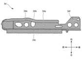
本実施形態に係る車両用シートSの基本構成について説明する。本実施形態に係る車両用シートSの基本構成は、公知である一般的な車両用シートと略同じ構成であり、図1に示すようにシートバックS1、シートクッションS2及びヘッドレストS3を有する。なお、図1中、車両用シートSの一部、具体的には、シートクッションS2の右側中央部については、説明の都合上、表皮材Rを外した構成にて図示している。<Basic configuration of vehicle seat S>
The basic configuration of the vehicle seat S according to this embodiment will be explained. The basic configuration of the vehicle seat S according to this embodiment is substantially the same as that of a known general vehicle seat, and includes a seat back S1, a seat cushion S2, and a headrest S3, as shown in FIG. In addition, in FIG. 1, a part of the vehicle seat S, specifically, the right center part of the seat cushion S2 is illustrated with the skin material R removed for convenience of explanation.
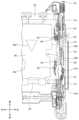
車両用シートSは、その骨格として、図2に図示のシートフレームFを有する。シートフレームFは、シートバックフレーム10と、シートクッションフレーム20と、を主な構成要素としている。シートバックS1及びシートクッションS2は、それぞれのフレーム(シートバックフレーム10及びシートクッションフレーム20)にウレタン等からなるクッションパッドUを置き、クッションパッドUの表面を表皮材Rで覆うことによって構成されている。 The vehicle seat S has a seat frame F shown in FIG. 2 as its skeleton. The seat frame F has a seat back
また、シートクッションS2の下部には、シートバックS1、シートクッションS2及びヘッドレストS3を前後方向にスライド移動させるためのスライドレール機構30が配置されている。スライドレール機構30は、図1に示すように隙間を隔てて左右一対設けられている。各スライドレール機構30は、図2に示すように、前後方向に延出した状態で車体に固定されているロアレール31と、ロアレール31の延出方向に沿って移動可能なアッパーレール32と、を有する。 Moreover, a
さらに、高さ方向においてシートクッションS2とスライドレール機構30との間には、シートクッションS2の高さを調整するための高さ調整機構40が備えられている。なお、高さ調整機構40を駆動させるための操作レバーLがシートクッションS2の脇位置に設けられている。 Furthermore, a
(シートバックフレーム10)
シートバックフレーム10は、図2に示すように、逆さU字形のアッパフレーム11と、シート幅方向両端部をなす左右一対のシートバックサイドフレーム12と、シートバックサイドフレーム12の下端部の間に架設されたロアメンバーフレーム13と、を有する。また、左右一対のシートバックサイドフレーム12のうち、一方のシートバックサイドフレーム12の下端部には、シートクッションS2に対するシートバックS1の傾斜角度を調整するリクライニング機構(不図示)が取り付けられる。(Seat back frame 10)
As shown in FIG. 2, the
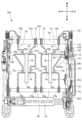
(シートクッションフレーム20)
シートクッションフレーム20は、図2に示すように、上方から見たときに方形枠状の外形形状を有しており、シート幅方向両端部に位置するシートクッションサイドフレーム21(サイドフレームに相当)と、シートクッションフレーム20の前端部を構成するパンフレーム22と、を主たる構成要素とする。また、シートクッションサイドフレーム21の後端部の上方部分には、連結ブラケット23が取り付けられている。この連結ブラケット23は、シートクッションサイドフレーム21とシートバックサイドフレーム12とを連結するために設けられた金属板部材である。(Seat cushion frame 20)
As shown in FIG. 2, the
各シートクッションサイドフレーム21は、前後方向に延びた金属鋼板によって構成されている。また、シートクッションサイドフレーム21は、対応するスライドレール機構30(より近い位置に在るスライドレール機構30)の直上位置にある。 Each seat
図2に示すように、左右一対のシートクッションサイドフレーム21の後端部同士が後側連結パイプ24によって連結されている。この後側連結パイプ24は、シート幅方向に沿って延出した丸パイプによって構成されている。さらに、図2に示すように、左右一対のシートクッションサイドフレーム21の前端部同士が前側連結パイプ25によって連結されている。この前側連結パイプ25は、シート幅方向に沿って延出した丸パイプによって構成されている。 As shown in FIG. 2, the rear end portions of the pair of left and right seat cushion side frames 21 are connected to each other by a rear
後側連結パイプ24及び前側連結パイプ25の各々は、シートクッションサイドフレーム21の間に配置されており、その端部は、シートクッションサイドフレーム21を貫通した状態でシートクッションサイドフレーム21に接合されている。 Each of the rear
図2及び図3に示すように、シートクッションフレーム20の後側連結パイプ24と前側連結パイプ25の間には、板状の受圧部材26が懸架されている。受圧部材26には、シート幅方向における側部26aに、内側に向かって窪んだ凹部26bが形成されている。図3に示されるように、受圧部材26の前方において、シート幅方向略中央の位置には、丸孔26cが1つ形成されている。また、受圧部材26の後方において、三角孔26dが2つシート幅方向に並んで形成されている。なお、受圧部材26の代わりに、パンフレーム22が後側連結パイプ24まで延びていてもよい。 As shown in FIGS. 2 and 3, a plate-shaped
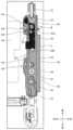
(スライドレール機構30)
スライドレール機構30は、ロアレール31及びアッパーレール32の他に、フット33、第1リンク支持ブラケット34及び第2リンク支持ブラケット35を有する(図4及び図5)。フット33は、ロアレール31を車体に固定するためにロアレール31の前端部に取り付けられる部材である。(Slide rail mechanism 30)
The
リンク支持ブラケットとしての第1リンク支持ブラケット34及び第2リンク支持ブラケット35は、それぞれシート幅方向に離間して左右一対設けられており、高さ調整機構40が備える回動リンク(具体的には後述のフロントリンク41及びリアリンク42)を支持する金属板部材である(図4乃至図7B)。 The first
(第1リンク支持ブラケット34)
第1リンク支持ブラケット34は、前後方向に長く延びており、フロント荷重検知センサー50及びリア荷重検知センサー60を介して、アッパーレール32の上面に固定されている。第1リンク支持ブラケット34は、図5、図6A及び図6Bに示すように、フロント荷重検知センサー50及びリア荷重検知センサー60が取付けられる底壁34aと、底壁34aから立設した内壁34b及び外壁34cを有する。(First link support bracket 34)
The first
図6Bに示すように、第1リンク支持ブラケット34の内壁34bは、シート幅方向内側に向かって折り曲げられている。また、図5及び図6Bに示すように、第1リンク支持ブラケット34の外壁34cは、シート幅方向外側に向かって逆U字形状に折り曲げられている。また、第1リンク支持ブラケット34の外壁34cの前端部には、後述するフロントリンク41の下端部の第2回動軸41bに対応する前方リンク孔34dが形成されている。 As shown in FIG. 6B, the
第1リンク支持ブラケット34の底壁34aの前方には、後述するフロント荷重検知センサー50の第1センサー軸51に対応する第1軸孔34eが形成されている。また、第1リンク支持ブラケット34の底壁34aの後方には、後述するリア荷重検知センサー60の第2センサー軸61に対応する第2軸孔34fが形成されている(図5及び図6A)。また、第1リンク支持ブラケット34の外壁34cの後端部には、後述するシートベルトのバックル支持ブラケット取付部Bに対応する後方孔34gが形成されている。 A
(第2リンク支持ブラケット35)
第2リンク支持ブラケット35は、第1リンク支持ブラケット34の後端に配置されており、リア荷重検知センサー60を介して、アッパーレール32の上面に固定されている。第2リンク支持ブラケット35は、図5、図7A及び図7Bに示すように、リア荷重検知センサー60が取付けられる底壁35aと、底壁35aから立設した内壁35bを有する。(Second link support bracket 35)
The second
図7Bに示すように、第2リンク支持ブラケット35の内壁35bの前方部分は、シート幅方向内側に向かって折り曲げられており、第1リンク支持ブラケット34の内壁34bに係合している。また、図7Bに示すように、第2リンク支持ブラケット35の内壁35bの後方には、後述するリアリンク42のリアリンク回動軸42aに対応する後方リンク孔35cが形成されている。 As shown in FIG. 7B, the front portion of the
第2リンク支持ブラケット35の底壁35aには、後述するリア荷重検知センサー60の前方のナットに対応するナット孔35dが形成されている(図5、図7A及び図7B)。また、第2リンク支持ブラケット35の底壁35aの後端部には、後述するリア荷重検知センサー60の第2センサー軸61に対応するようにしてシート幅方向内側に向かって窪んだ切欠部35eが形成されている。 The
第1リンク支持ブラケット34の底壁34aの上に、第2リンク支持ブラケット35の底壁35aが重ねられ、溶接部Yにおいて溶接されている(図5、図10A及び図10B)。 The
(高さ調整機構40)
高さ調整機構40は、回動リンクの回動により、シートクッションS2の高さを調整する。回動リンクは、左右それぞれに2つずつ配置されている。具体的に説明すると、左右一対設けられたスライドレール機構30の各々の上方位置には2つの回動リンクが配置されている。当該2つの回動リンクは、前後方向(すなわち、ロアレール31の延出方向)において互いに離れている。(Height adjustment mechanism 40)
The
前方の回動リンクは、第1リンク部材に相当し、以下ではフロントリンク41と呼ぶこととする。より後方の回動リンクは、第2リンク部材に相当し、以下ではリアリンク42と呼ぶこととする。フロントリンク41は、前後方向においてリアリンク42よりも前側連結パイプ25に近い位置に配置されている。換言すると、前側連結パイプ25は、リアリンク42よりもフロントリンク41に近い位置に配置されている。 The front pivot link corresponds to a first link member and will be referred to as a
各回動リンクは、金属製の板材によって構成されており、所定形状にプレス加工されている。フロントリンク41の表面には、シート幅方向内側に窪んだリブが第1回動軸41aと第2回動軸41bの間に延びるようにして形成されている(図9)。また、リアリンク42の表面には、シート幅方向外側に窪んだリブがリアリンク回動軸42aと後端部42bの間に延びるようにして形成されている(図10A及び図10B)。 Each rotation link is made of a metal plate and is pressed into a predetermined shape. A rib recessed inward in the seat width direction is formed on the surface of the
以下、高さ調整機構40の構造について図8乃至図12Bを参照しながら説明する。高さ調整機構40において、回動リンクであるフロントリンク41及びリアリンク42の双方は、シートクッションS2及びアッパーレール32の各々に対して回動可能な状態で支持されている。 The structure of the
具体的に説明すると、フロントリンク41は、その下端部の第2回動軸41bにおいて、前方リンク孔34dと重なった状態で、ピボットピンを介して第1リンク支持ブラケット34に対して回動可能な状態で支持されている(図8及び図9)。 Specifically, the
また、リアリンク42は、その下端部のリアリンク回動軸42aにおいて、後方リンク孔35cと重なった状態で、ピボットピンを介して第2リンク支持ブラケット35に対して回動可能な状態で支持されている(図10A及び図10B)。 Further, the
さらに、シート前後方向においてシートクッションサイドフレーム21の中央部分よりもやや前方寄りの部分には、フロントリンク41の上端部が第1回動軸41aにおいてピボットピンを介して回動可能な状態で支持されている(図8及び図9)。さらに、シートクッションサイドフレーム21の後端部には、リアリンク42の後端部42bが後側連結パイプ24において回動可能な状態で支持されている(図10A及び図10B)。 Furthermore, the upper end portion of the
ここで、リアリンク42の上端部の支持構造について詳述すると、リアリンク42の上端部は、図10Bに示すように側面視で略扇形状となっており、その中央部分には貫通孔が形成されている。この貫通孔には、図10Bに示すように、後側連結パイプ24の端部が嵌合して溶接されている。 Here, to explain in detail the support structure of the upper end of the
後側連結パイプ24は、シートクッションサイドフレーム21に対して相対回転可能な状態でシートクッションサイドフレーム21に支持されている。これにより、リアリンク42の上端部は、シートクッションサイドフレーム21に対して相対回動可能となる。 The
このように、フロントリンク41及びリアリンク42は、アッパーレール32に固定されたリンク支持ブラケット(第1リンク支持ブラケット34及び第2リンク支持ブラケット35)、シートクッションサイドフレーム21とともに4節リンクを構成している。そして、図示しない電動または手動のアクチュエータによりフロントリンク41又はリアリンク42をシートクッションサイドフレーム21に対して回動させることにより、シートクッションS2の高さを変えることができるようになっている。 In this way, the
具体的には、フロントリンク41又はリアリンク42の一方が回動すると、これに従動する形で他方の回動リンクが同じ向きに回動する。この際、各回動リンクは、シートクッションフレーム20を連れ回るように回動する(換言すると、シートクッションS2とともに回動する)。この結果、シートクッションフレーム20(つまり、シートクッションS2の位置)が図11A及び図11Bに示す最上方位置と、図12A及び図12Bに示す最下方位置との間で昇降し、シートクッションS2の高さが調整されることになる。 Specifically, when one of the
(荷重検知センサー)
本実施形態の車両用シートSでは、ベースとしてのスライドレール機構30のアッパーレール32の上面に車両用シートSに掛かる荷重を検出する荷重検知センサーが締結部材(ボルトとナット)によって取り付けられている。より詳細には、アッパーレール32の前方には第1荷重検知センサーとしてのフロント荷重検知センサー50が第1前側締結部材55及び第1後側締結部材56によって取り付けられており、アッパーレール32の後方には第2荷重検知センサーとしてのリア荷重検知センサー60が第2前側締結部材65及び第2後側締結部材66によって取り付けられている。フロント荷重検知センサー50及びリア荷重検知センサー60は、従来公知の歪みセンサーである。(Load detection sensor)
In the vehicle seat S of this embodiment, a load detection sensor for detecting the load applied to the vehicle seat S is attached to the upper surface of the
フロント荷重検知センサー50及びリア荷重検知センサー60は、シート幅方向において離間した一対のアッパーレール32のうち少なくとも一方側に設けられていればよい。なお、スライドレール機構30を備えない車両用シートSの場合、フロント荷重検知センサー50及びリア荷重検知センサー60は、ベースとしての車体フロア(不図示)に直接取り付けられる。 The front
図9に示すように、フロント荷重検知センサー50は、上方から荷重が印加される第1センサー軸51を、前方の第1センサー前端52と後方の第1センサー後端53の間に有している。フロント荷重検知センサー50は、第1センサー後端53に、外部の電子機器(電子制御ユニット)と接続するための第1カプラ54(センサコネクタ)を備えている。 As shown in FIG. 9, the front
車両用シートSに着座する乗員の荷重が、第1センサー軸51を介してセンサー基板である第1起歪体51aに印加されると、第1起歪体51aに撓みが生じる。フロント荷重検知センサー50は、車両用シートSに着座する乗員の荷重を、第1起歪体51aに生じる撓みとして測定するように構成されている。 When the load of an occupant seated on the vehicle seat S is applied to the
図9に示すように、リア荷重検知センサー60は、上方から荷重が印加される第2センサー軸61を、前方の第2センサー前端62と後方の第2センサー後端63の間に有している。リア荷重検知センサー60は、第2センサー後端63に、外部の電子機器(電子制御ユニット)と接続するための第2カプラ64(センサコネクタ)を備えている。 As shown in FIG. 9, the rear
車両用シートSに着座する乗員の荷重が、第2センサー軸61を介してセンサー基板である第2起歪体61aに印加されると、第2起歪体61aに撓みが生じる。リア荷重検知センサー60は、車両用シートSに着座する乗員の荷重を、第2起歪体61aに生じる撓みとして測定するように構成されている。 When the load of an occupant seated on the vehicle seat S is applied to the
図5、図8及び図9に示されるように、第1起歪体51aは、第1リンク支持ブラケット34の底壁34aの下面に位置し、第1センサー軸51の上端部51bは、第1リンク支持ブラケット34の底壁34aの第1軸孔34eから上方に露出している。また、第2起歪体61aは、第1リンク支持ブラケット34の底壁34aの下面に位置し、第2センサー軸61の上端部は、第1リンク支持ブラケット34の底壁34aの第2軸孔34fから上方に露出している。 As shown in FIGS. 5, 8 and 9, the
このような構成により、本実施形態の車両用シートSでは、リンク支持ブラケット(第1リンク支持ブラケット34及び第2リンク支持ブラケット35)が、回動リンク(フロントリンク41及びリアリンク42)を適切に支持しつつ、車両用シートSに着座する乗員の荷重が、第1センサー軸51を介して第1起歪体51aに効率的に印加されるようになっている。 With such a configuration, in the vehicle seat S of the present embodiment, the link support brackets (the first
(各部材間の位置関係について)
本実施形態の車両用シートSでは、各構成要素が以下に述べるように、適切な位置関係で配置されているため、高さ調整機構40及び荷重検知センサーを備えつつ、高さ方向及び幅方向におけるサイズが大型化することが抑制されている。(About the positional relationship between each member)
In the vehicle seat S of this embodiment, since each component is arranged in an appropriate positional relationship as described below, it is equipped with a
フロント荷重検知センサー50は、シート前後方向において、フロントリンク41の第2回動軸41bとは異なる位置に配置されている(図9)。より詳細には、フロント荷重検知センサー50の第1センサー前端52よりも前方に、フロントリンク41の第2回動軸41bが配置されている(図9)。このようにシート前後方向において、高さ調整機構40を構成するフロントリンク41の第2回動軸41bが、フロント荷重検知センサー50と異なる位置に配置されておりオーバーラップしないため、車両用シートSが高さ方向で大型化することが抑制される。 The front
また、フロント荷重検知センサー50の第1センサー軸51は、シート上下方向において、フロントリンク41の第2回動軸41bの少なくとも一部と同じ高さ位置に配置されている(図9)。このように、第2回動軸41bと第1センサー軸51が同じ高さ位置に配置されていると、車両用シートSが高さ方向で大型化することが抑制される。 Further, the
また、図9に示されるように、シート上下方向において、フロントリンク41の第2回動軸41bの上端部41cは、第1センサー軸51の上端部51bよりも下方に配置されており、車両用シートSが高さ方向で大型化することが抑制されている。 Further, as shown in FIG. 9, the
また、図9に示されるように、シートクッションS2が最下方位置にあるときに、シート上下方向において、フロント荷重検知センサー50の少なくとも一部は、シートクッションフレーム20の後側連結パイプ24と同じ高さ位置に配置されており、車両用シートSが高さ方向で大型化することが抑制されている。 Further, as shown in FIG. 9, when the seat cushion S2 is at the lowest position, at least a portion of the front
また、シートクッションサイドフレーム21は、シート幅方向において、フロントリンク41及びリアリンク42の間に配置されており(図9及び図10)、第1センサー軸51は、シート幅方向において、フロントリンク41及びリアリンク42の間に配置されている(図3及び図5)。このような構成によれば、車両用シートSが幅方向で大型化することが抑制される。 Further, the seat
また、リア荷重検知センサー60の第2センサー軸61は、シート幅方向において、フロントリンク41及びリアリンク42の間に配置されており(図3、図5及び図14)、車両用シートSが幅方向で大型化することが抑制されている。 Further, the
また、リアリンク42は、シート幅方向において、シートクッションサイドフレーム21及びリア荷重検知センサー60の第2カプラ64の間に配置されている(図15)。このようにシート幅方向において、シートクッションサイドフレーム21及び第2カプラ64の間の範囲内にリアリンク42が収まっていることで、その分、車両用シートSがよりコンパクトになっている。 Further, the
また、リア荷重検知センサー60の第2カプラ64は、シート前後方向において、リアリンク42と同じ位置に配置されており(図10B)、コンパクトな配置となっている。また、図10Bに示すように、リアリンク42のリアリンク回動軸42aは、シート上下方向において、第2センサー軸61と同じ高さ位置に配置されている。 Further, the
また、フロントリンク41及びリアリンク42は、リンク支持ブラケット(第1リンク支持ブラケット34及び第2リンク支持ブラケット35)に取り付けられており、フロント荷重検知センサー50及びリア荷重検知センサー60は、リンク支持ブラケットに取り付けられている(図5)。ここで、図8に示されるように、第1リンク支持ブラケット34は、前端から後方に向かうにつれて上方に屈曲しており、フロント荷重検知センサー50の取付位置と第2荷重検知センサーの取付位置の間(換言すると、第1センサー軸51と第2センサー軸61の間)においてスライドレール機構30のアッパーレール32と離間している。このような構成によれば、車両用シートSを構成する部品数を抑制しつつ、リンク支持ブラケット自体の剛性が向上する。 Further, the
また、シート前後方向において、受圧部材26の側部26aに設けられた凹部26bは、フロント荷重検知センサー50とリア荷重検知センサー60の間に配置されている。このように、受圧部材26の凹みが、シート前後方向においてコンパクトに配置されるため、受圧部材26の剛性が低下することが抑制される。 Further, in the seat longitudinal direction, the
<変形例>
本発明は上記の実施形態に限定されるものではない。図16に示されるように、変形例に係る車両用シートSのシートクッションフレーム20xを上方から見た部分断面図である。図16に示すように、シートクッションフレーム20xの後側連結パイプ24と前側連結パイプ25の間には、ワイヤー状スプリング70、71、72、73が懸架されている。<Modified example>
The present invention is not limited to the embodiments described above. As shown in FIG. 16, it is a partial sectional view of a
ワイヤー状スプリング70は、前端70a及び後端70bの間に、前方から順にスプリング凹部70c、スプリング凸部70d、スプリング凹部70eを備えている。また、ワイヤー状スプリング71は、前端71a及び後端71bの間に、前方から順にスプリング凹部71c及びスプリング凹部71dを備えている。また、ワイヤー状スプリング72は、前端72a及び後端72bの間に、前方から順にスプリング凹部72c及びスプリング凹部72dを備えている。また、ワイヤー状スプリング73は、前端73a及び後端73bの間に、前方から順にスプリング凹部73c、スプリング凸部73d、スプリング凹部73eを備えている。 The wire-
図16に示されるように、ワイヤー状スプリング73のスプリング凸部73dは、リア荷重検知センサー60の第2センサー前端62に配置された第2カプラ64(センサコネクタ)がシート幅方向において対向する位置に配置されている。また、シート上下方向において、スプリング凸部73d及び第2カプラ64(センサコネクタ)は、互いにオーバーラップしないように配置されている。 As shown in FIG. 16, the spring
このような配置によれば、スプリング凹部73c又はスプリング凹部73eが第2カプラ64とシート幅方向で対向する位置に配置される場合と比較して、ワイヤー状スプリング73で乗員を支持する面積をシート幅方向に大きくすることが可能となる。 According to this arrangement, compared to the case where the
ワイヤー状スプリング70とワイヤー状スプリング71の間は、後方において後方連結部材74によって連結されており、前方において前方連結部材75によって連結されている。また、後方連結部材74と前方連結部材75は、シート前後方向に延在する樹脂部材76によって連結されている。樹脂部材76はある程度の弾性力を備えており、前端76a及び後端76bを備えている。樹脂部材76は、前端76aが自由端となっており、後端76bは固定端となっている。 The
樹脂部材76は、リア荷重検知センサー60の第2センサー前端62に配置された第2カプラ64(センサコネクタ)よりも後方の位置を起点として前方に延出しており、前方連結部材75を越えて延出することで、シート前後方向に長く配置されている。 The
図17は、他の変形例に係る車両用シートのシートクッションフレームの側面図である。図17に示されるように、フロントリンク41の第1回動軸41a側の後端部には、フロントリンク41の回動範囲を規制するストッパ部としてのフランジ41xが形成されている。 FIG. 17 is a side view of a seat cushion frame of a vehicle seat according to another modification. As shown in FIG. 17, a
シートクッションS2が最下方位置にあるときに、フランジ41xが第1リンク支持ブラケット34xの外壁34cの上面(当接部)に当接する。このようにして、フランジ41xは、フロントリンク41が、それ以上下方へと回動することを規制する。なお、フランジ41xの突出量は、シート幅方向において、第1リンク支持ブラケット34xの外壁34cの上面(当接部)の外側の端部よりも内側までに設定されることで、コンパクトに形成されている。 When the seat cushion S2 is in the lowermost position, the
第1リンク支持ブラケット34xの外壁34cの上面は、上方に突出するか、又は下方に凹んでおり、フランジ41xの受け部として機能するようになっている。さらに、第1リンク支持ブラケット34の外壁34cの上面には、弾性部材としてのゴムが取り付けられていても良い。 The upper surface of the
図17に示されるように、フロント荷重検知センサー50がフロントリンク41の第2回動軸41bよりも前方に配置されていてもよい。
シートクッションS2が最下方位置にあるときに、フロント荷重検知センサー50の後側取付部材としての第1後側締結部材56は、第2回動軸41bよりも前方に配置されており、フロント荷重検知センサー50は全体的に第2回動軸41bよりも前方に配置される。このような構成により、フロントリンク41にストッパ部としてのフランジ41xを備えた場合にフロント荷重検知センサー50とフロントリンク41が干渉することや、設計上、シート構造が上下方向に大型化してしまうことを抑制可能となる。As shown in FIG. 17, the front
When the seat cushion S2 is in the lowermost position, the first
S 車両用シート(乗物用シート)
S1 シートバック
S2 シートクッション
S3 ヘッドレスト
R 表皮材
U クッションパッド
L 操作レバー
F シートフレーム
10 シートバックフレーム
11 アッパフレーム
12 シートバックサイドフレーム
13 ロアメンバーフレーム
20、20x シートクッションフレーム
21 シートクッションサイドフレーム(サイドフレーム)
22 パンフレーム
23 連結ブラケット
24 後側連結パイプ(連結部材)
25 前側連結パイプ
26 受圧部材
26a 側部
26b 凹部
26c 丸孔
26d 三角孔
30 スライドレール機構(ベース)
31 ロアレール
32 アッパーレール
33 フット
34、34x 第1リンク支持ブラケット(リンク支持ブラケット)
34a 底壁
34b 内壁
34c 外壁
34d 前方リンク孔
34e 第1軸孔
34f 第2軸孔
34g 後方孔
35 第2リンク支持ブラケット(リンク支持ブラケット)
35a 底壁
35b 内壁
35c 後方リンク孔
35d ナット孔
35e 切欠部
40 高さ調整機構
41 フロントリンク(第1リンク部材)
41a 第1回動軸
41b 第2回動軸
41c 上端部
41x フランジ
42 リアリンク(第2リンク部材)
42a リアリンク回動軸
42b 後端部
50 フロント荷重検知センサー(第1荷重検知センサー)
51 第1センサー軸
51a 第1起歪体
51b 上端部
52 第1センサー前端
53 第1センサー後端
54 第1カプラ
55 第1前側締結部材
56 第1後側締結部材
60 リア荷重検知センサー(第2荷重検知センサー)
61 第2センサー軸
61a 第2起歪体
62 第2センサー前端
63 第2センサー後端
64 第2カプラ
65 第2前側締結部材
66 第2後側締結部材
B バックル支持ブラケット取付部
Y 溶接部
70、71、72、73 ワイヤー状スプリング(受圧部材)
70a、71a、72a、73a 前端
70b、71b、72b、73b 後端
70c、71c、72c、73c スプリング凹部
70d、73d スプリング凸部
70e、71d、72d、73e スプリング凹部
74 後方連結部材
75 前方連結部材
76 樹脂部材
76a 前端
76b 前端S Vehicle seat (vehicle seat)
S1 Seat back S2 Seat cushion S3 Headrest R Outer skin material U Cushion pad L Operation lever
22
25
31
41a
42a Rear
51
61
70a, 71a, 72a, 73a
Claims (10)
Translated fromJapaneseシートクッションフレームを備えるシートクッションと、
スライドレール又は車体フロアであるベースに対して前記シートクッションの高さを調整する第1リンク部材と、
前記ベースに取り付けられ、前記乗物用シートに掛かる荷重を検出する第1荷重検知センサーと、を有し、
前記シートクッションフレームは、前記乗物用シートの幅方向に離間して設けられた一対のサイドフレームと、一対の前記サイドフレームの間を連結する連結部材を有し、
前記第1リンク部材は、前記シートクッションフレームに対して回動可能な第1回動軸と、前記ベースに対して回動可能な第2回動軸と、を有し、
前記第1荷重検知センサーは、前記乗物用シートの前後方向において、前記第2回動軸とは異なる位置に配置されており、
前記シートクッションが最下方位置にあるときに、前記乗物用シートの上下方向において、前記第1荷重検知センサーの少なくとも一部は、前記連結部材と同じ高さ位置に配置されていることを特徴とする乗物用シート。A vehicle seat,
a seat cushion including a seat cushion frame;
a first link member that adjusts the height of the seat cushion with respect to a base that is a slide rail or a vehicle floor;
a first load detection sensor attached to the base and configured to detect a load applied to the vehicle seat;
The seat cushion frame has a pair of side frames provided apart from each other in the width direction of the vehicle seat, and a connecting member that connects the pair of side frames,
The first link member has a first rotation shaft rotatable with respect to the seat cushion frame and a second rotation shaft rotatable with respect to the base,
The first load detection sensor is disposed at a position different from the second rotation axis in the longitudinal direction of the vehicle seat,
At least a portion of the first load detection sensor is disposed at the same height position as the connecting member in the vertical direction of the vehicle seat when the seat cushion is at the lowest position. vehicle seat.
前記乗物用シートの上下方向において、前記第2回動軸の少なくとも一部は、前記第1センサー軸と同じ高さ位置に配置されていることを特徴とする請求項1に記載の乗物用シート。The first load detection sensor has a first sensor shaft to which a load applied to the vehicle seat is applied;
2. The vehicle seat according to claim 1, wherein at least a portion of the second rotation shaft is located at the same height as the first sensor shaft in the vertical direction of the vehicle seat. .
前記サイドフレームは、前記乗物用シートの幅方向において、前記第1リンク部材及び前記第2リンク部材の間に配置されており、
前記第1センサー軸は、前記乗物用シートの幅方向において、前記第1リンク部材及び前記第2リンク部材の間に配置されていることを特徴とする請求項2又は3に記載の乗物用シート。a second link member that adjusts the height of the seat cushion with respect to the base, located at a position rearward of the first link member;
The side frame is disposed between the first link member and the second link member in the width direction of the vehicle seat,
The vehicle seat according to claim 2 or 3, wherein the first sensor shaft is arranged between the first link member and the second link member in the width direction of the vehicle seat. .
前記第2荷重検知センサーは、前記乗物用シートに掛かる荷重が印加される第2センサー軸を有し、
前記第2センサー軸は、前記乗物用シートの幅方向において、前記第1リンク部材及び前記第2リンク部材の間に配置されていることを特徴とする請求項4に記載の乗物用シート。a second load detection sensor attached to the base and configured to detect a load applied to the vehicle seat, the second load detection sensor being located at a rearward position than the first load detection sensor;
The second load detection sensor has a second sensor shaft to which a load applied to the vehicle seat is applied;
The vehicle seat according to claim 4, wherein the second sensor shaft is disposed between the first link member and the second link member in the width direction of the vehicle seat.
前記ベースに取り付けられ、前記乗物用シートに掛かる荷重を検出する第2荷重検知センサーを前記第1荷重検知センサーよりも後方位置に有し、
前記第2荷重検知センサーは、外部の電子機器と接続するためのカプラを備え、
前記第2リンク部材は、前記乗物用シートの幅方向において、前記サイドフレーム及び前記カプラの間に配置されていることを特徴とする請求項1乃至3のいずれか一項に記載の乗物用シート。a second link member that adjusts the height of the seat cushion with respect to the base, located at a position rearward of the first link member;
a second load detection sensor attached to the base and configured to detect a load applied to the vehicle seat, the second load detection sensor being located at a rearward position than the first load detection sensor;
The second load detection sensor includes a coupler for connecting to an external electronic device,
The vehicle seat according to any one of claims 1 to 3, wherein the second link member is arranged between the side frame and the coupler in the width direction of the vehicle seat. .
前記ベースに取り付けられ、前記乗物用シートに掛かる荷重を検出する第2荷重検知センサーを前記第1荷重検知センサーよりも後方位置に有し、
前記第1リンク部材及び前記第2リンク部材は、リンク支持ブラケットに取り付けられており、
前記第1荷重検知センサー及び前記第2荷重検知センサーは、前記リンク支持ブラケットに取り付けられており、
前記リンク支持ブラケットは、上方に屈曲しており、前記第1荷重検知センサーの取付位置と前記第2荷重検知センサーの取付位置の間において前記ベースと離間していることを特徴とする請求項1乃至3のいずれか一項に記載の乗物用シート。a second link member that adjusts the height of the seat cushion with respect to the base, located at a position rearward of the first link member;
a second load detection sensor attached to the base and configured to detect a load applied to the vehicle seat, the second load detection sensor being located at a rearward position than the first load detection sensor;
The first link member and the second link member are attached to a link support bracket,
The first load detection sensor and the second load detection sensor are attached to the link support bracket,
Claim 1, wherein the link support bracket is bent upward and is spaced apart from the base between the mounting position of the first load detection sensor and the mounting position of the second load detection sensor. The vehicle seat according to any one of items 3 to 3.
前記乗物用シートの幅方向において、前記受圧部材の側部には内側に向かって窪んだ凹部が形成されており、
前記ベースに取り付けられ、前記乗物用シートに掛かる荷重を検出する第2荷重検知センサーを前記第1荷重検知センサーよりも後方位置に有し、
前記乗物用シートの前後方向において、前記凹部は、前記第1荷重検知センサーと前記第2荷重検知センサーの間に配置されていることを特徴とする請求項1乃至3のいずれか一項に記載の乗物用シート。comprising a plate-shaped pressure receiving member suspended on the seat cushion frame,
In the width direction of the vehicle seat, a concave portion recessed toward the inside is formed in a side portion of the pressure receiving member;
a second load detection sensor attached to the base and configured to detect a load applied to the vehicle seat, the second load detection sensor being located at a rearward position than the first load detection sensor;
According to any one of claims 1 to 3, the recess is disposed between the first load detection sensor and the second load detection sensor in the front-rear direction of the vehicle seat. vehicle seat.
前記シートバックフレームは、逆さU字形のアッパフレームと、シート幅方向両端部をなす一対のシートバックサイドフレームと、一対の前記シートバックサイドフレームの下端部の間に架設されたロアメンバーフレームと、を有し、
前記サイドフレームの後端部の上方部分には、前記サイドフレームと前記シートバックサイドフレームとを連結する連結ブラケットが取り付けられており、
一対の前記シートバックサイドフレームのうち、一方の前記シートバックサイドフレームの下端部には、前記シートクッションに対する前記シートバックの傾斜角度を調整するリクライニング機構が取り付けられており、
前記シートバック及び前記シートクッションは、前記シートバックフレーム及び前記シートクッションフレームに載置されたクッションパッドと、前記クッションパッドの表面を覆う表皮材と、を有していることを特徴とする請求項1乃至9のいずれか一項に記載の乗物用シート。The vehicle seat includes a seat back including a seat back frame,
The seat back frame includes an inverted U-shaped upper frame, a pair of seat back side frames forming both ends in the seat width direction, and a lower member frame constructed between the lower ends of the pair of seat back side frames. has
A connection bracket that connects the side frame and the seat back side frame is attached to an upper portion of the rear end of the side frame,
A reclining mechanism that adjusts the inclination angle of the seat back with respect to the seat cushion is attached to the lower end of one of the pair of seat back side frames,
The seat back and the seat cushion include a cushion pad placed on the seat back frame and the seat cushion frame, and a skin material covering a surface of the cushion pad. 10. The vehicle seat according to any one of 1 to 9.
Priority Applications (7)
| Application Number | Priority Date | Filing Date | Title |
|---|---|---|---|
| JP2019132011AJP7421060B2 (en) | 2019-07-17 | 2019-07-17 | vehicle seat |
| US16/928,400US11420537B2 (en) | 2019-07-17 | 2020-07-14 | Conveyance seat |
| US17/890,307US11794614B2 (en) | 2019-07-17 | 2022-08-18 | Conveyance seat |
| JP2023105201AJP7541261B2 (en) | 2019-07-17 | 2023-06-27 | Vehicle seats |
| US18/466,072US12179641B2 (en) | 2019-07-17 | 2023-09-13 | Conveyance seat |
| JP2024135434AJP2024149788A (en) | 2019-07-17 | 2024-08-14 | Vehicle seats |
| US18/950,477US20250074267A1 (en) | 2019-07-17 | 2024-11-18 | Conveyance seat |
Applications Claiming Priority (1)
| Application Number | Priority Date | Filing Date | Title |
|---|---|---|---|
| JP2019132011AJP7421060B2 (en) | 2019-07-17 | 2019-07-17 | vehicle seat |
Related Child Applications (1)
| Application Number | Title | Priority Date | Filing Date |
|---|---|---|---|
| JP2023105201ADivisionJP7541261B2 (en) | 2019-07-17 | 2023-06-27 | Vehicle seats |
Publications (2)
| Publication Number | Publication Date |
|---|---|
| JP2021017077A JP2021017077A (en) | 2021-02-15 |
| JP7421060B2true JP7421060B2 (en) | 2024-01-24 |
Family
ID=74343305
Family Applications (3)
| Application Number | Title | Priority Date | Filing Date |
|---|---|---|---|
| JP2019132011AActiveJP7421060B2 (en) | 2019-07-17 | 2019-07-17 | vehicle seat |
| JP2023105201AActiveJP7541261B2 (en) | 2019-07-17 | 2023-06-27 | Vehicle seats |
| JP2024135434APendingJP2024149788A (en) | 2019-07-17 | 2024-08-14 | Vehicle seats |
Family Applications After (2)
| Application Number | Title | Priority Date | Filing Date |
|---|---|---|---|
| JP2023105201AActiveJP7541261B2 (en) | 2019-07-17 | 2023-06-27 | Vehicle seats |
| JP2024135434APendingJP2024149788A (en) | 2019-07-17 | 2024-08-14 | Vehicle seats |
Country Status (2)
| Country | Link |
|---|---|
| US (4) | US11420537B2 (en) |
| JP (3) | JP7421060B2 (en) |
Families Citing this family (1)
| Publication number | Priority date | Publication date | Assignee | Title |
|---|---|---|---|---|
| KR102218451B1 (en)* | 2019-08-09 | 2021-02-19 | 주식회사 포스코 | Seat frame |
Citations (3)
| Publication number | Priority date | Publication date | Assignee | Title |
|---|---|---|---|---|
| JP2008002999A (en) | 2006-06-23 | 2008-01-10 | Aisin Seiki Co Ltd | Vehicle seat load detection device |
| JP2017154533A (en) | 2016-02-29 | 2017-09-07 | トヨタ紡織株式会社 | Vehicle seat |
| JP2018199353A (en) | 2017-05-25 | 2018-12-20 | テイ・エス テック株式会社 | Seat frame |
Family Cites Families (32)
| Publication number | Priority date | Publication date | Assignee | Title |
|---|---|---|---|---|
| JP4099683B2 (en)* | 1998-09-25 | 2008-06-11 | アイシン精機株式会社 | Vehicle seat |
| JP3729119B2 (en)* | 2001-10-23 | 2005-12-21 | アイシン精機株式会社 | Vehicle seat seating load detection device |
| DE10239385B4 (en)* | 2002-08-28 | 2014-07-17 | Volkswagen Ag | Vehicle seat with height adjustment device and seat load detection |
| US6940026B2 (en)* | 2002-12-09 | 2005-09-06 | Robert Bosch Corporation | Method and system for vehicle occupant weight sensing |
| DE10303826B3 (en) | 2003-01-31 | 2004-04-15 | Keiper Gmbh & Co. Kg | Motor vehicle seat weight sensor for use in conjunction with an air-bag safety system, has a sensor device the main part of which is incorporated within the seat rail |
| WO2006099746A1 (en)* | 2005-03-24 | 2006-09-28 | Intelligent Mechatronic Systems Inc. | Automotive weight sensor for occupant classification system |
| DE102005060480B4 (en) | 2005-12-15 | 2007-11-22 | Faurecia Autositze Gmbh | Automotive seat |
| JP2009036564A (en)* | 2007-07-31 | 2009-02-19 | Nissan Motor Co Ltd | Vehicle seat load detection system |
| JP2011105298A (en)* | 2009-10-22 | 2011-06-02 | Aisin Seiki Co Ltd | Apparatus and method for determining seat occupancy |
| JP5589694B2 (en)* | 2009-10-22 | 2014-09-17 | アイシン精機株式会社 | Seating determination device and seating determination method |
| JP5593993B2 (en)* | 2009-10-22 | 2014-09-24 | アイシン精機株式会社 | Seat occupant determination device |
| JP5651188B2 (en)* | 2010-10-12 | 2015-01-07 | テイ・エス テック株式会社 | Vehicle seat |
| US9038487B2 (en) | 2011-07-28 | 2015-05-26 | Ts Tech Co., Ltd. | Support structure for load measurement sensor |
| US9151644B2 (en) | 2011-07-28 | 2015-10-06 | Ts Tech Co., Ltd. | Load measurement sensor support structure |
| US9121748B2 (en) | 2011-07-28 | 2015-09-01 | Ts Tech Co., Ltd. | Support structure for load measurement sensor |
| US20140224553A1 (en) | 2011-08-10 | 2014-08-14 | Ts Tech Co., Ltd. | Load measurement sensor support structure |
| US9352666B2 (en)* | 2011-08-10 | 2016-05-31 | Ts Tech Co., Ltd. | Vehicle seat |
| DE102013221542B4 (en)* | 2013-08-05 | 2023-06-29 | Brose Fahrzeugteile SE & Co. Kommanditgesellschaft, Coburg | Vehicle seat with catch element |
| US9085246B1 (en)* | 2014-01-17 | 2015-07-21 | GM Global Technology Operations LLC | Vehicle seat stabilization assembly |
| FR3049536B1 (en)* | 2016-03-31 | 2018-03-23 | Peugeot Citroen Automobiles Sa | ADJUSTABLE SEAT STRUCTURE OF A VEHICLE SEAT COMPRISING A BELT BUCKLE OF A SAFETY BELT. |
| JP6668947B2 (en)* | 2016-05-26 | 2020-03-18 | トヨタ紡織株式会社 | Vehicle seat |
| JP6475278B2 (en)* | 2017-03-24 | 2019-02-27 | 本田技研工業株式会社 | Vehicle seat |
| JP6482587B2 (en)* | 2017-03-24 | 2019-03-13 | テイ・エス テック株式会社 | Vehicle seat |
| US10086723B1 (en)* | 2017-03-30 | 2018-10-02 | Ts Tech Co., Ltd. | Vehicle seat |
| US10442322B2 (en)* | 2017-11-17 | 2019-10-15 | Brose Fahrzeugteile Gmbh & Co. Kommanditgesellschaft | Easy-entry vehicle seat |
| CN107933381B (en)* | 2017-12-12 | 2023-09-15 | 湖北中航精机科技有限公司 | Seat height adjusting device and seat |
| DE102018115499A1 (en)* | 2018-06-27 | 2020-01-02 | Faurecia Autositze Gmbh | Base for a vehicle seat and vehicle seat |
| WO2020054678A1 (en)* | 2018-09-12 | 2020-03-19 | テイ・エス テック株式会社 | Vehicle seat |
| US11072308B2 (en)* | 2018-11-27 | 2021-07-27 | Mazda Motor Corporation | Seat structure for vehicle |
| JP6705995B2 (en) | 2019-02-18 | 2020-06-03 | テイ・エス テック株式会社 | Vehicle seat |
| KR102805145B1 (en)* | 2019-12-10 | 2025-05-08 | 현대자동차주식회사 | Device for tilting seat chusion of fold and dive seat |
| CN113715699B (en)* | 2021-10-13 | 2022-09-09 | 延锋国际座椅系统有限公司 | Zero-gravity seat adjusting mechanism for automobile |
- 2019
- 2019-07-17JPJP2019132011Apatent/JP7421060B2/enactiveActive
- 2020
- 2020-07-14USUS16/928,400patent/US11420537B2/enactiveActive
- 2022
- 2022-08-18USUS17/890,307patent/US11794614B2/enactiveActive
- 2023
- 2023-06-27JPJP2023105201Apatent/JP7541261B2/enactiveActive
- 2023-09-13USUS18/466,072patent/US12179641B2/enactiveActive
- 2024
- 2024-08-14JPJP2024135434Apatent/JP2024149788A/enactivePending
- 2024-11-18USUS18/950,477patent/US20250074267A1/enactivePending
Patent Citations (3)
| Publication number | Priority date | Publication date | Assignee | Title |
|---|---|---|---|---|
| JP2008002999A (en) | 2006-06-23 | 2008-01-10 | Aisin Seiki Co Ltd | Vehicle seat load detection device |
| JP2017154533A (en) | 2016-02-29 | 2017-09-07 | トヨタ紡織株式会社 | Vehicle seat |
| JP2018199353A (en) | 2017-05-25 | 2018-12-20 | テイ・エス テック株式会社 | Seat frame |
Also Published As
| Publication number | Publication date |
|---|---|
| JP7541261B2 (en) | 2024-08-28 |
| US20230415620A1 (en) | 2023-12-28 |
| US20250074267A1 (en) | 2025-03-06 |
| JP2021017077A (en) | 2021-02-15 |
| US12179641B2 (en) | 2024-12-31 |
| US11794614B2 (en) | 2023-10-24 |
| US20210016690A1 (en) | 2021-01-21 |
| US11420537B2 (en) | 2022-08-23 |
| JP2024149788A (en) | 2024-10-18 |
| JP2023115163A (en) | 2023-08-18 |
| US20220388431A1 (en) | 2022-12-08 |
Similar Documents
| Publication | Publication Date | Title |
|---|---|---|
| US20210276462A1 (en) | Vehicle seat | |
| JP5396978B2 (en) | Vehicle seat | |
| CN108437866B (en) | Seat device | |
| US20220219572A1 (en) | Vehicle seat | |
| JP2024149788A (en) | Vehicle seats | |
| WO2001039632A1 (en) | Seat back frame assembly of vehicle seat | |
| CN104512282A (en) | Vehicle seat | |
| JP7428553B2 (en) | vehicle seat | |
| JP5733936B2 (en) | Vehicle seat | |
| JP7348464B2 (en) | vehicle seat | |
| JP7514168B2 (en) | Vehicle seat | |
| JP7386207B2 (en) | vehicle seat | |
| JP7011153B2 (en) | Vehicle seat | |
| JP2024036594A (en) | vehicle seat | |
| CN117529423A (en) | vehicle seats | |
| JP6159561B2 (en) | Vehicle seat | |
| JP2024036619A5 (en) | ||
| JP2021055379A (en) | Cab and work vehicle |
Legal Events
| Date | Code | Title | Description |
|---|---|---|---|
| A621 | Written request for application examination | Free format text:JAPANESE INTERMEDIATE CODE: A621 Effective date:20220628 | |
| A977 | Report on retrieval | Free format text:JAPANESE INTERMEDIATE CODE: A971007 Effective date:20230328 | |
| A131 | Notification of reasons for refusal | Free format text:JAPANESE INTERMEDIATE CODE: A131 Effective date:20230509 | |
| A521 | Request for written amendment filed | Free format text:JAPANESE INTERMEDIATE CODE: A523 Effective date:20230626 | |
| A521 | Request for written amendment filed | Free format text:JAPANESE INTERMEDIATE CODE: A523 Effective date:20230629 | |
| A521 | Request for written amendment filed | Free format text:JAPANESE INTERMEDIATE CODE: A821 Effective date:20230626 | |
| A131 | Notification of reasons for refusal | Free format text:JAPANESE INTERMEDIATE CODE: A131 Effective date:20231010 | |
| A521 | Request for written amendment filed | Free format text:JAPANESE INTERMEDIATE CODE: A523 Effective date:20231101 | |
| TRDD | Decision of grant or rejection written | ||
| A01 | Written decision to grant a patent or to grant a registration (utility model) | Free format text:JAPANESE INTERMEDIATE CODE: A01 Effective date:20231212 | |
| A61 | First payment of annual fees (during grant procedure) | Free format text:JAPANESE INTERMEDIATE CODE: A61 Effective date:20231225 | |
| R150 | Certificate of patent or registration of utility model | Ref document number:7421060 Country of ref document:JP Free format text:JAPANESE INTERMEDIATE CODE: R150 |