JP7420846B2 - kidney pump - Google Patents
kidney pumpDownload PDFInfo
- Publication number
- JP7420846B2 JP7420846B2JP2022031553AJP2022031553AJP7420846B2JP 7420846 B2JP7420846 B2JP 7420846B2JP 2022031553 AJP2022031553 AJP 2022031553AJP 2022031553 AJP2022031553 AJP 2022031553AJP 7420846 B2JP7420846 B2JP 7420846B2
- Authority
- JP
- Japan
- Prior art keywords
- blood
- impeller
- applications
- cage
- pump
- Prior art date
- Legal status (The legal status is an assumption and is not a legal conclusion. Google has not performed a legal analysis and makes no representation as to the accuracy of the status listed.)
- Active
Links
- 210000003734kidneyAnatomy0.000titledescription30
- 238000000034methodMethods0.000claimsdescription354
- 239000000463materialSubstances0.000claimsdescription177
- 238000005520cutting processMethods0.000claimsdescription85
- 230000008878couplingEffects0.000claimsdescription37
- 238000010168coupling processMethods0.000claimsdescription37
- 238000005859coupling reactionMethods0.000claimsdescription37
- 238000003780insertionMethods0.000claimsdescription35
- 230000037431insertionEffects0.000claimsdescription35
- 238000004804windingMethods0.000claimsdescription21
- 238000004519manufacturing processMethods0.000claimsdescription19
- 210000004369bloodAnatomy0.000description770
- 239000008280bloodSubstances0.000description770
- 210000004204blood vesselAnatomy0.000description610
- 210000002796renal veinAnatomy0.000description467
- 238000005086pumpingMethods0.000description160
- 238000011144upstream manufacturingMethods0.000description136
- 230000017531blood circulationEffects0.000description122
- 210000003462veinAnatomy0.000description115
- 230000004044responseEffects0.000description94
- 210000005166vasculatureAnatomy0.000description72
- 239000012530fluidSubstances0.000description68
- 230000007246mechanismEffects0.000description65
- 230000001965increasing effectEffects0.000description55
- 230000036772blood pressureEffects0.000description52
- 238000004891communicationMethods0.000description46
- 206010019280Heart failuresDiseases0.000description39
- 206010007559Cardiac failure congestiveDiseases0.000description36
- 238000010586diagramMethods0.000description36
- 230000008327renal blood flowEffects0.000description33
- 230000002792vascularEffects0.000description30
- 230000000747cardiac effectEffects0.000description28
- 210000004027cellAnatomy0.000description27
- 230000033001locomotionEffects0.000description26
- 238000000926separation methodMethods0.000description25
- 238000010438heat treatmentMethods0.000description23
- 230000006835compressionEffects0.000description22
- 238000007906compressionMethods0.000description22
- 239000003146anticoagulant agentSubstances0.000description21
- 229940127219anticoagulant drugDrugs0.000description21
- 210000002700urineAnatomy0.000description21
- 230000004064dysfunctionEffects0.000description19
- 239000011295pitchSubstances0.000description19
- 208000037849arterial hypertensionDiseases0.000description17
- 239000012528membraneSubstances0.000description17
- 230000008085renal dysfunctionEffects0.000description17
- 230000001276controlling effectEffects0.000description16
- 239000002934diureticSubstances0.000description16
- 230000010412perfusionEffects0.000description14
- 101800000407Brain natriuretic peptide 32Proteins0.000description13
- 230000009467reductionEffects0.000description13
- 238000000108ultra-filtrationMethods0.000description13
- 102000002723Atrial Natriuretic FactorHuman genes0.000description11
- 101800001288Atrial natriuretic factorProteins0.000description11
- 101800001890Atrial natriuretic peptideProteins0.000description11
- NSQLIUXCMFBZME-MPVJKSABSA-NcarperitideChemical compoundC([C@H]1C(=O)NCC(=O)NCC(=O)N[C@@H](CCCNC(N)=N)C(=O)N[C@@H](CCSC)C(=O)N[C@@H](CC(O)=O)C(=O)N[C@@H](CCCNC(N)=N)C(=O)N[C@H](C(NCC(=O)N[C@@H](C)C(=O)N[C@@H](CCC(N)=O)C(=O)N[C@@H](CO)C(=O)NCC(=O)N[C@@H](CC(C)C)C(=O)NCC(=O)N[C@@H](CSSC[C@@H](C(=O)N1)NC(=O)[C@H](CO)NC(=O)[C@H](CO)NC(=O)[C@H](CCCNC(N)=N)NC(=O)[C@H](CCCNC(N)=N)NC(=O)[C@H](CC(C)C)NC(=O)[C@@H](N)CO)C(=O)N[C@@H](CC(N)=O)C(=O)N[C@@H](CO)C(=O)N[C@@H](CC=1C=CC=CC=1)C(=O)N[C@@H](CCCNC(N)=N)C(=O)N[C@@H](CC=1C=CC(O)=CC=1)C(O)=O)=O)[C@@H](C)CC)C1=CC=CC=C1NSQLIUXCMFBZME-MPVJKSABSA-N0.000description11
- 229920001971elastomerPolymers0.000description11
- 239000000806elastomerSubstances0.000description11
- 239000007788liquidSubstances0.000description11
- 229920001296polysiloxanePolymers0.000description11
- 208000007536ThrombosisDiseases0.000description10
- 230000008859changeEffects0.000description10
- 238000002474experimental methodMethods0.000description10
- 238000011282treatmentMethods0.000description10
- 230000001882diuretic effectEffects0.000description9
- 238000001035dryingMethods0.000description9
- 210000005245right atriumAnatomy0.000description9
- 230000001154acute effectEffects0.000description8
- 208000006440Open BiteDiseases0.000description7
- 229940030606diureticsDrugs0.000description7
- 210000003191femoral veinAnatomy0.000description7
- 238000009434installationMethods0.000description7
- 210000005241right ventricleAnatomy0.000description6
- 241000282887SuidaeSpecies0.000description5
- 238000004873anchoringMethods0.000description5
- 230000001746atrial effectEffects0.000description5
- 230000007423decreaseEffects0.000description5
- 230000003247decreasing effectEffects0.000description5
- 238000007598dipping methodMethods0.000description5
- 230000000694effectsEffects0.000description5
- 230000029142excretionEffects0.000description5
- 238000011010flushing procedureMethods0.000description5
- 230000004217heart functionEffects0.000description5
- 229910001000nickel titaniumInorganic materials0.000description5
- HLXZNVUGXRDIFK-UHFFFAOYSA-Nnickel titaniumChemical compound[Ti].[Ti].[Ti].[Ti].[Ti].[Ti].[Ti].[Ti].[Ti].[Ti].[Ti].[Ni].[Ni].[Ni].[Ni].[Ni].[Ni].[Ni].[Ni].[Ni].[Ni].[Ni].[Ni].[Ni].[Ni]HLXZNVUGXRDIFK-UHFFFAOYSA-N0.000description5
- 230000007704transitionEffects0.000description5
- 206010018910HaemolysisDiseases0.000description4
- DGAQECJNVWCQMB-PUAWFVPOSA-MIlexoside XXIXChemical compoundC[C@@H]1CC[C@@]2(CC[C@@]3(C(=CC[C@H]4[C@]3(CC[C@@H]5[C@@]4(CC[C@@H](C5(C)C)OS(=O)(=O)[O-])C)C)[C@@H]2[C@]1(C)O)C)C(=O)O[C@H]6[C@@H]([C@H]([C@@H]([C@H](O6)CO)O)O)O.[Na+]DGAQECJNVWCQMB-PUAWFVPOSA-M0.000description4
- 206010062237Renal impairmentDiseases0.000description4
- 230000004913activationEffects0.000description4
- 230000001919adrenal effectEffects0.000description4
- 230000015572biosynthetic processEffects0.000description4
- DDRJAANPRJIHGJ-UHFFFAOYSA-NcreatinineChemical compoundCN1CC(=O)NC1=NDDRJAANPRJIHGJ-UHFFFAOYSA-N0.000description4
- 230000008588hemolysisEffects0.000description4
- 230000002440hepatic effectEffects0.000description4
- 230000001771impaired effectEffects0.000description4
- 230000006872improvementEffects0.000description4
- 230000000977initiatory effectEffects0.000description4
- 230000000968intestinal effectEffects0.000description4
- 239000011344liquid materialSubstances0.000description4
- 230000008288physiological mechanismEffects0.000description4
- 238000006116polymerization reactionMethods0.000description4
- 231100000857poor renal functionToxicity0.000description4
- 230000004043responsivenessEffects0.000description4
- 229910052708sodiumInorganic materials0.000description4
- 239000011734sodiumSubstances0.000description4
- 208000027418Wounds and injuryDiseases0.000description3
- 230000003213activating effectEffects0.000description3
- 230000004872arterial blood pressureEffects0.000description3
- 230000006378damageEffects0.000description3
- 230000006870functionEffects0.000description3
- 208000014674injuryDiseases0.000description3
- 210000004185liverAnatomy0.000description3
- 238000011866long-term treatmentMethods0.000description3
- 238000005259measurementMethods0.000description3
- 230000004048modificationEffects0.000description3
- 238000012986modificationMethods0.000description3
- 230000002644neurohormonal effectEffects0.000description3
- 210000000056organAnatomy0.000description3
- 230000001105regulatory effectEffects0.000description3
- 238000007493shaping processMethods0.000description3
- 239000007787solidSubstances0.000description3
- 210000001321subclavian veinAnatomy0.000description3
- 230000009885systemic effectEffects0.000description3
- 235000010082Averrhoa carambolaNutrition0.000description2
- 240000006063Averrhoa carambolaSpecies0.000description2
- 206010020565HyperaemiaDiseases0.000description2
- XEEYBQQBJWHFJM-UHFFFAOYSA-NIronChemical compound[Fe]XEEYBQQBJWHFJM-UHFFFAOYSA-N0.000description2
- 208000004880PolyuriaDiseases0.000description2
- 230000002159abnormal effectEffects0.000description2
- 210000001367arteryAnatomy0.000description2
- QVGXLLKOCUKJST-UHFFFAOYSA-Natomic oxygenChemical compound[O]QVGXLLKOCUKJST-UHFFFAOYSA-N0.000description2
- 238000009530blood pressure measurementMethods0.000description2
- 230000008602contractionEffects0.000description2
- 229940109239creatinineDrugs0.000description2
- 238000002788crimpingMethods0.000description2
- 230000035619diuresisEffects0.000description2
- 229940079593drugDrugs0.000description2
- 239000003814drugSubstances0.000description2
- 238000011049fillingMethods0.000description2
- 230000024924glomerular filtrationEffects0.000description2
- 210000003111iliac veinAnatomy0.000description2
- 210000004731jugular veinAnatomy0.000description2
- 238000003698laser cuttingMethods0.000description2
- 229910052760oxygenInorganic materials0.000description2
- 239000001301oxygenSubstances0.000description2
- 238000005192partitionMethods0.000description2
- 230000001991pathophysiological effectEffects0.000description2
- 230000000737periodic effectEffects0.000description2
- 229920000728polyesterPolymers0.000description2
- 229920002635polyurethanePolymers0.000description2
- 239000004814polyurethaneSubstances0.000description2
- 239000011148porous materialSubstances0.000description2
- 210000002254renal arteryAnatomy0.000description2
- 238000011160researchMethods0.000description2
- 230000002441reversible effectEffects0.000description2
- 238000007789sealingMethods0.000description2
- 230000008467tissue growthEffects0.000description2
- 230000009724venous congestionEffects0.000description2
- PQSUYGKTWSAVDQ-ZVIOFETBSA-NAldosteroneChemical compoundC([C@@]1([C@@H](C(=O)CO)CC[C@H]1[C@@H]1CC2)C=O)[C@H](O)[C@@H]1[C@]1(C)C2=CC(=O)CC1PQSUYGKTWSAVDQ-ZVIOFETBSA-N0.000description1
- PQSUYGKTWSAVDQ-UHFFFAOYSA-NAldosteroneNatural productsC1CC2C3CCC(C(=O)CO)C3(C=O)CC(O)C2C2(C)C1=CC(=O)CC2PQSUYGKTWSAVDQ-UHFFFAOYSA-N0.000description1
- 206010003445AscitesDiseases0.000description1
- 206010003658Atrial FibrillationDiseases0.000description1
- 208000037157AzotemiaDiseases0.000description1
- 208000004990Cardiorenal syndromeDiseases0.000description1
- 102000003951ErythropoietinHuman genes0.000description1
- 108090000394ErythropoietinProteins0.000description1
- 206010016803Fluid overloadDiseases0.000description1
- 206010059484HaemodilutionDiseases0.000description1
- XOJVVFBFDXDTEG-UHFFFAOYSA-NNorphytaneNatural productsCC(C)CCCC(C)CCCC(C)CCCC(C)CXOJVVFBFDXDTEG-UHFFFAOYSA-N0.000description1
- 102100028255ReninHuman genes0.000description1
- 108090000783ReninProteins0.000description1
- FAPWRFPIFSIZLT-UHFFFAOYSA-MSodium chlorideChemical compound[Na+].[Cl-]FAPWRFPIFSIZLT-UHFFFAOYSA-M0.000description1
- 201000001943Tricuspid Valve InsufficiencyDiseases0.000description1
- 206010044640Tricuspid valve incompetenceDiseases0.000description1
- 238000009825accumulationMethods0.000description1
- 230000009471actionEffects0.000description1
- 229960002478aldosteroneDrugs0.000description1
- 208000007502anemiaDiseases0.000description1
- 230000002785anti-thrombosisEffects0.000description1
- 210000000709aortaAnatomy0.000description1
- 210000002376aorta thoracicAnatomy0.000description1
- 230000002051biphasic effectEffects0.000description1
- 210000001124body fluidAnatomy0.000description1
- 239000010839body fluidSubstances0.000description1
- 210000002665bowman capsuleAnatomy0.000description1
- 210000004556brainAnatomy0.000description1
- 210000001175cerebrospinal fluidAnatomy0.000description1
- 230000003205diastolic effectEffects0.000description1
- 230000002708enhancing effectEffects0.000description1
- 229940105423erythropoietinDrugs0.000description1
- 230000002496gastric effectEffects0.000description1
- 230000001434glomerularEffects0.000description1
- 230000028709inflammatory responseEffects0.000description1
- 238000007917intracranial administrationMethods0.000description1
- 150000002500ionsChemical class0.000description1
- 229910052742ironInorganic materials0.000description1
- 238000005304joiningMethods0.000description1
- 230000003907kidney functionEffects0.000description1
- 210000005240left ventricleAnatomy0.000description1
- 230000007774longtermEffects0.000description1
- 210000004072lungAnatomy0.000description1
- 238000012423maintenanceMethods0.000description1
- 230000013011matingEffects0.000description1
- 210000003205muscleAnatomy0.000description1
- 230000037361pathwayEffects0.000description1
- 230000002093peripheral effectEffects0.000description1
- 230000037081physical activityEffects0.000description1
- 229920003023plasticPolymers0.000description1
- 239000004033plasticSubstances0.000description1
- OXCMYAYHXIHQOA-UHFFFAOYSA-Npotassium;[2-butyl-5-chloro-3-[[4-[2-(1,2,4-triaza-3-azanidacyclopenta-1,4-dien-5-yl)phenyl]phenyl]methyl]imidazol-4-yl]methanolChemical compound[K+].CCCCC1=NC(Cl)=C(CO)N1CC1=CC=C(C=2C(=CC=CC=2)C2=N[N-]N=N2)C=C1OXCMYAYHXIHQOA-UHFFFAOYSA-N0.000description1
- 230000002028prematureEffects0.000description1
- 210000002307prostateAnatomy0.000description1
- 230000001681protective effectEffects0.000description1
- 102000004169proteins and genesHuman genes0.000description1
- 108090000623proteins and genesProteins0.000description1
- 238000010992refluxMethods0.000description1
- 239000012781shape memory materialSubstances0.000description1
- 229910001285shape-memory alloyInorganic materials0.000description1
- 238000004513sizingMethods0.000description1
- 239000011780sodium chlorideSubstances0.000description1
- 210000004872soft tissueAnatomy0.000description1
- 238000000638solvent extractionMethods0.000description1
- 239000010935stainless steelSubstances0.000description1
- 229910001220stainless steelInorganic materials0.000description1
- 230000008961swellingEffects0.000description1
- 208000024891symptomDiseases0.000description1
- 238000002560therapeutic procedureMethods0.000description1
- 210000000591tricuspid valveAnatomy0.000description1
- 210000003708urethraAnatomy0.000description1
- 210000001631vena cava inferiorAnatomy0.000description1
- 230000002861ventricularEffects0.000description1
Images


Classifications
- A—HUMAN NECESSITIES
- A61—MEDICAL OR VETERINARY SCIENCE; HYGIENE
- A61F—FILTERS IMPLANTABLE INTO BLOOD VESSELS; PROSTHESES; DEVICES PROVIDING PATENCY TO, OR PREVENTING COLLAPSING OF, TUBULAR STRUCTURES OF THE BODY, e.g. STENTS; ORTHOPAEDIC, NURSING OR CONTRACEPTIVE DEVICES; FOMENTATION; TREATMENT OR PROTECTION OF EYES OR EARS; BANDAGES, DRESSINGS OR ABSORBENT PADS; FIRST-AID KITS
- A61F2/00—Filters implantable into blood vessels; Prostheses, i.e. artificial substitutes or replacements for parts of the body; Appliances for connecting them with the body; Devices providing patency to, or preventing collapsing of, tubular structures of the body, e.g. stents
- A61F2/02—Prostheses implantable into the body
- A61F2/04—Hollow or tubular parts of organs, e.g. bladders, tracheae, bronchi or bile ducts
- A61F2/06—Blood vessels
- A61F2/07—Stent-grafts
- A—HUMAN NECESSITIES
- A61—MEDICAL OR VETERINARY SCIENCE; HYGIENE
- A61B—DIAGNOSIS; SURGERY; IDENTIFICATION
- A61B5/00—Measuring for diagnostic purposes; Identification of persons
- A61B5/02—Detecting, measuring or recording for evaluating the cardiovascular system, e.g. pulse, heart rate, blood pressure or blood flow
- A61B5/0205—Simultaneously evaluating both cardiovascular conditions and different types of body conditions, e.g. heart and respiratory condition
- A61B5/02055—Simultaneously evaluating both cardiovascular condition and temperature
- A—HUMAN NECESSITIES
- A61—MEDICAL OR VETERINARY SCIENCE; HYGIENE
- A61M—DEVICES FOR INTRODUCING MEDIA INTO, OR ONTO, THE BODY; DEVICES FOR TRANSDUCING BODY MEDIA OR FOR TAKING MEDIA FROM THE BODY; DEVICES FOR PRODUCING OR ENDING SLEEP OR STUPOR
- A61M60/00—Blood pumps; Devices for mechanical circulatory actuation; Balloon pumps for circulatory assistance
- A61M60/10—Location thereof with respect to the patient's body
- A61M60/122—Implantable pumps or pumping devices, i.e. the blood being pumped inside the patient's body
- A61M60/126—Implantable pumps or pumping devices, i.e. the blood being pumped inside the patient's body implantable via, into, inside, in line, branching on, or around a blood vessel
- A61M60/13—Implantable pumps or pumping devices, i.e. the blood being pumped inside the patient's body implantable via, into, inside, in line, branching on, or around a blood vessel by means of a catheter allowing explantation, e.g. catheter pumps temporarily introduced via the vascular system
- A—HUMAN NECESSITIES
- A61—MEDICAL OR VETERINARY SCIENCE; HYGIENE
- A61M—DEVICES FOR INTRODUCING MEDIA INTO, OR ONTO, THE BODY; DEVICES FOR TRANSDUCING BODY MEDIA OR FOR TAKING MEDIA FROM THE BODY; DEVICES FOR PRODUCING OR ENDING SLEEP OR STUPOR
- A61M60/00—Blood pumps; Devices for mechanical circulatory actuation; Balloon pumps for circulatory assistance
- A61M60/10—Location thereof with respect to the patient's body
- A61M60/122—Implantable pumps or pumping devices, i.e. the blood being pumped inside the patient's body
- A61M60/126—Implantable pumps or pumping devices, i.e. the blood being pumped inside the patient's body implantable via, into, inside, in line, branching on, or around a blood vessel
- A61M60/135—Implantable pumps or pumping devices, i.e. the blood being pumped inside the patient's body implantable via, into, inside, in line, branching on, or around a blood vessel inside a blood vessel, e.g. using grafting
- A—HUMAN NECESSITIES
- A61—MEDICAL OR VETERINARY SCIENCE; HYGIENE
- A61M—DEVICES FOR INTRODUCING MEDIA INTO, OR ONTO, THE BODY; DEVICES FOR TRANSDUCING BODY MEDIA OR FOR TAKING MEDIA FROM THE BODY; DEVICES FOR PRODUCING OR ENDING SLEEP OR STUPOR
- A61M60/00—Blood pumps; Devices for mechanical circulatory actuation; Balloon pumps for circulatory assistance
- A61M60/20—Type thereof
- A61M60/205—Non-positive displacement blood pumps
- A61M60/216—Non-positive displacement blood pumps including a rotating member acting on the blood, e.g. impeller
- A61M60/237—Non-positive displacement blood pumps including a rotating member acting on the blood, e.g. impeller the blood flow through the rotating member having mainly axial components, e.g. axial flow pumps
- A—HUMAN NECESSITIES
- A61—MEDICAL OR VETERINARY SCIENCE; HYGIENE
- A61M—DEVICES FOR INTRODUCING MEDIA INTO, OR ONTO, THE BODY; DEVICES FOR TRANSDUCING BODY MEDIA OR FOR TAKING MEDIA FROM THE BODY; DEVICES FOR PRODUCING OR ENDING SLEEP OR STUPOR
- A61M60/00—Blood pumps; Devices for mechanical circulatory actuation; Balloon pumps for circulatory assistance
- A61M60/30—Medical purposes thereof other than the enhancement of the cardiac output
- A61M60/31—Medical purposes thereof other than the enhancement of the cardiac output for enhancement of in vivo organ perfusion, e.g. retroperfusion
- A61M60/33—Medical purposes thereof other than the enhancement of the cardiac output for enhancement of in vivo organ perfusion, e.g. retroperfusion of kidneys
- A—HUMAN NECESSITIES
- A61—MEDICAL OR VETERINARY SCIENCE; HYGIENE
- A61M—DEVICES FOR INTRODUCING MEDIA INTO, OR ONTO, THE BODY; DEVICES FOR TRANSDUCING BODY MEDIA OR FOR TAKING MEDIA FROM THE BODY; DEVICES FOR PRODUCING OR ENDING SLEEP OR STUPOR
- A61M60/00—Blood pumps; Devices for mechanical circulatory actuation; Balloon pumps for circulatory assistance
- A61M60/40—Details relating to driving
- A61M60/403—Details relating to driving for non-positive displacement blood pumps
- A61M60/408—Details relating to driving for non-positive displacement blood pumps the force acting on the blood contacting member being mechanical, e.g. transmitted by a shaft or cable
- A61M60/411—Details relating to driving for non-positive displacement blood pumps the force acting on the blood contacting member being mechanical, e.g. transmitted by a shaft or cable generated by an electromotor
- A—HUMAN NECESSITIES
- A61—MEDICAL OR VETERINARY SCIENCE; HYGIENE
- A61M—DEVICES FOR INTRODUCING MEDIA INTO, OR ONTO, THE BODY; DEVICES FOR TRANSDUCING BODY MEDIA OR FOR TAKING MEDIA FROM THE BODY; DEVICES FOR PRODUCING OR ENDING SLEEP OR STUPOR
- A61M60/00—Blood pumps; Devices for mechanical circulatory actuation; Balloon pumps for circulatory assistance
- A61M60/40—Details relating to driving
- A61M60/403—Details relating to driving for non-positive displacement blood pumps
- A61M60/422—Details relating to driving for non-positive displacement blood pumps the force acting on the blood contacting member being electromagnetic, e.g. using canned motor pumps
- A—HUMAN NECESSITIES
- A61—MEDICAL OR VETERINARY SCIENCE; HYGIENE
- A61M—DEVICES FOR INTRODUCING MEDIA INTO, OR ONTO, THE BODY; DEVICES FOR TRANSDUCING BODY MEDIA OR FOR TAKING MEDIA FROM THE BODY; DEVICES FOR PRODUCING OR ENDING SLEEP OR STUPOR
- A61M60/00—Blood pumps; Devices for mechanical circulatory actuation; Balloon pumps for circulatory assistance
- A61M60/50—Details relating to control
- A61M60/508—Electronic control means, e.g. for feedback regulation
- A61M60/515—Regulation using real-time patient data
- A61M60/523—Regulation using real-time patient data using blood flow data, e.g. from blood flow transducers
- A—HUMAN NECESSITIES
- A61—MEDICAL OR VETERINARY SCIENCE; HYGIENE
- A61M—DEVICES FOR INTRODUCING MEDIA INTO, OR ONTO, THE BODY; DEVICES FOR TRANSDUCING BODY MEDIA OR FOR TAKING MEDIA FROM THE BODY; DEVICES FOR PRODUCING OR ENDING SLEEP OR STUPOR
- A61M60/00—Blood pumps; Devices for mechanical circulatory actuation; Balloon pumps for circulatory assistance
- A61M60/80—Constructional details other than related to driving
- A61M60/802—Constructional details other than related to driving of non-positive displacement blood pumps
- A61M60/804—Impellers
- A61M60/806—Vanes or blades
- A61M60/808—Vanes or blades specially adapted for deformable impellers, e.g. expandable impellers
- A—HUMAN NECESSITIES
- A61—MEDICAL OR VETERINARY SCIENCE; HYGIENE
- A61M—DEVICES FOR INTRODUCING MEDIA INTO, OR ONTO, THE BODY; DEVICES FOR TRANSDUCING BODY MEDIA OR FOR TAKING MEDIA FROM THE BODY; DEVICES FOR PRODUCING OR ENDING SLEEP OR STUPOR
- A61M60/00—Blood pumps; Devices for mechanical circulatory actuation; Balloon pumps for circulatory assistance
- A61M60/80—Constructional details other than related to driving
- A61M60/802—Constructional details other than related to driving of non-positive displacement blood pumps
- A61M60/81—Pump housings
- A—HUMAN NECESSITIES
- A61—MEDICAL OR VETERINARY SCIENCE; HYGIENE
- A61M—DEVICES FOR INTRODUCING MEDIA INTO, OR ONTO, THE BODY; DEVICES FOR TRANSDUCING BODY MEDIA OR FOR TAKING MEDIA FROM THE BODY; DEVICES FOR PRODUCING OR ENDING SLEEP OR STUPOR
- A61M60/00—Blood pumps; Devices for mechanical circulatory actuation; Balloon pumps for circulatory assistance
- A61M60/80—Constructional details other than related to driving
- A61M60/802—Constructional details other than related to driving of non-positive displacement blood pumps
- A61M60/818—Bearings
- A61M60/825—Contact bearings, e.g. ball-and-cup or pivot bearings
- A—HUMAN NECESSITIES
- A61—MEDICAL OR VETERINARY SCIENCE; HYGIENE
- A61M—DEVICES FOR INTRODUCING MEDIA INTO, OR ONTO, THE BODY; DEVICES FOR TRANSDUCING BODY MEDIA OR FOR TAKING MEDIA FROM THE BODY; DEVICES FOR PRODUCING OR ENDING SLEEP OR STUPOR
- A61M60/00—Blood pumps; Devices for mechanical circulatory actuation; Balloon pumps for circulatory assistance
- A61M60/80—Constructional details other than related to driving
- A61M60/802—Constructional details other than related to driving of non-positive displacement blood pumps
- A61M60/833—Occluders for preventing backflow
- A—HUMAN NECESSITIES
- A61—MEDICAL OR VETERINARY SCIENCE; HYGIENE
- A61M—DEVICES FOR INTRODUCING MEDIA INTO, OR ONTO, THE BODY; DEVICES FOR TRANSDUCING BODY MEDIA OR FOR TAKING MEDIA FROM THE BODY; DEVICES FOR PRODUCING OR ENDING SLEEP OR STUPOR
- A61M60/00—Blood pumps; Devices for mechanical circulatory actuation; Balloon pumps for circulatory assistance
- A61M60/80—Constructional details other than related to driving
- A61M60/855—Constructional details other than related to driving of implantable pumps or pumping devices
- A61M60/861—Connections or anchorings for connecting or anchoring pumps or pumping devices to parts of the patient's body
- A—HUMAN NECESSITIES
- A61—MEDICAL OR VETERINARY SCIENCE; HYGIENE
- A61M—DEVICES FOR INTRODUCING MEDIA INTO, OR ONTO, THE BODY; DEVICES FOR TRANSDUCING BODY MEDIA OR FOR TAKING MEDIA FROM THE BODY; DEVICES FOR PRODUCING OR ENDING SLEEP OR STUPOR
- A61M2207/00—Methods of manufacture, assembly or production
- A—HUMAN NECESSITIES
- A61—MEDICAL OR VETERINARY SCIENCE; HYGIENE
- A61M—DEVICES FOR INTRODUCING MEDIA INTO, OR ONTO, THE BODY; DEVICES FOR TRANSDUCING BODY MEDIA OR FOR TAKING MEDIA FROM THE BODY; DEVICES FOR PRODUCING OR ENDING SLEEP OR STUPOR
- A61M2210/00—Anatomical parts of the body
- A61M2210/10—Trunk
- A61M2210/1078—Urinary tract
- A61M2210/1082—Kidney
- A—HUMAN NECESSITIES
- A61—MEDICAL OR VETERINARY SCIENCE; HYGIENE
- A61M—DEVICES FOR INTRODUCING MEDIA INTO, OR ONTO, THE BODY; DEVICES FOR TRANSDUCING BODY MEDIA OR FOR TAKING MEDIA FROM THE BODY; DEVICES FOR PRODUCING OR ENDING SLEEP OR STUPOR
- A61M2210/00—Anatomical parts of the body
- A61M2210/12—Blood circulatory system
- A—HUMAN NECESSITIES
- A61—MEDICAL OR VETERINARY SCIENCE; HYGIENE
- A61M—DEVICES FOR INTRODUCING MEDIA INTO, OR ONTO, THE BODY; DEVICES FOR TRANSDUCING BODY MEDIA OR FOR TAKING MEDIA FROM THE BODY; DEVICES FOR PRODUCING OR ENDING SLEEP OR STUPOR
- A61M60/00—Blood pumps; Devices for mechanical circulatory actuation; Balloon pumps for circulatory assistance
- A61M60/10—Location thereof with respect to the patient's body
- A61M60/122—Implantable pumps or pumping devices, i.e. the blood being pumped inside the patient's body
- A61M60/126—Implantable pumps or pumping devices, i.e. the blood being pumped inside the patient's body implantable via, into, inside, in line, branching on, or around a blood vessel
- A61M60/148—Implantable pumps or pumping devices, i.e. the blood being pumped inside the patient's body implantable via, into, inside, in line, branching on, or around a blood vessel in line with a blood vessel using resection or like techniques, e.g. permanent endovascular heart assist devices
- A—HUMAN NECESSITIES
- A61—MEDICAL OR VETERINARY SCIENCE; HYGIENE
- A61M—DEVICES FOR INTRODUCING MEDIA INTO, OR ONTO, THE BODY; DEVICES FOR TRANSDUCING BODY MEDIA OR FOR TAKING MEDIA FROM THE BODY; DEVICES FOR PRODUCING OR ENDING SLEEP OR STUPOR
- A61M60/00—Blood pumps; Devices for mechanical circulatory actuation; Balloon pumps for circulatory assistance
- A61M60/40—Details relating to driving
- A61M60/403—Details relating to driving for non-positive displacement blood pumps
- A61M60/408—Details relating to driving for non-positive displacement blood pumps the force acting on the blood contacting member being mechanical, e.g. transmitted by a shaft or cable
- A61M60/411—Details relating to driving for non-positive displacement blood pumps the force acting on the blood contacting member being mechanical, e.g. transmitted by a shaft or cable generated by an electromotor
- A61M60/414—Details relating to driving for non-positive displacement blood pumps the force acting on the blood contacting member being mechanical, e.g. transmitted by a shaft or cable generated by an electromotor transmitted by a rotating cable, e.g. for blood pumps mounted on a catheter
- A—HUMAN NECESSITIES
- A61—MEDICAL OR VETERINARY SCIENCE; HYGIENE
- A61M—DEVICES FOR INTRODUCING MEDIA INTO, OR ONTO, THE BODY; DEVICES FOR TRANSDUCING BODY MEDIA OR FOR TAKING MEDIA FROM THE BODY; DEVICES FOR PRODUCING OR ENDING SLEEP OR STUPOR
- A61M60/00—Blood pumps; Devices for mechanical circulatory actuation; Balloon pumps for circulatory assistance
- A61M60/80—Constructional details other than related to driving
- A61M60/855—Constructional details other than related to driving of implantable pumps or pumping devices
- A61M60/89—Valves
- A61M60/894—Passive valves, i.e. valves actuated by the blood
- A61M60/896—Passive valves, i.e. valves actuated by the blood having flexible or resilient parts, e.g. flap valves
Landscapes
- Health & Medical Sciences (AREA)
- Heart & Thoracic Surgery (AREA)
- Engineering & Computer Science (AREA)
- Cardiology (AREA)
- Life Sciences & Earth Sciences (AREA)
- Biomedical Technology (AREA)
- Animal Behavior & Ethology (AREA)
- General Health & Medical Sciences (AREA)
- Public Health (AREA)
- Veterinary Medicine (AREA)
- Hematology (AREA)
- Anesthesiology (AREA)
- Mechanical Engineering (AREA)
- Vascular Medicine (AREA)
- Transplantation (AREA)
- Pulmonology (AREA)
- Medical Informatics (AREA)
- Physics & Mathematics (AREA)
- Physiology (AREA)
- Gastroenterology & Hepatology (AREA)
- Oral & Maxillofacial Surgery (AREA)
- Urology & Nephrology (AREA)
- Optics & Photonics (AREA)
- Biophysics (AREA)
- Pathology (AREA)
- Molecular Biology (AREA)
- Surgery (AREA)
- External Artificial Organs (AREA)
- Structures Of Non-Positive Displacement Pumps (AREA)
Description
Translated fromJapanese関連出願の相互参照
本出願は、Schwammenthalによって2013年3月13日に出願された「Renal pump」という表題の米国仮特許出願第61/779,803号、および、Schwammenthalによって2013年12月11日に出願された「Renal pump」という表題の米国仮特許出願61/914,475号の優先権を主張する。CROSS-REFERENCE TO RELATED APPLICATIONS This application is filed in U.S. Provisional Patent Application No. 61/779,803, entitled "Renal pump," filed on March 13, 2013 by Schwammenthal, and filed on December 11, 2013 by Schwammenthal. Claims priority to U.S. Provisional Patent Application No. 61/914,475, entitled "Renal Pump," filed in 1999.
本出願は、Tuvalによって2013年6月6日に出願された「Prosthetic renal valve」という表題の国際特許出願PCT/IL2013/050495(WO13/183060として公開された)に関連しており、それは、Tuvalによって2012年6月6日に出願された「Prosthetic renal valve」という表題の米国仮特許出願第61/656,244号の優先権を主張する。 The present application is related to the international patent application PCT/IL2013/050495 (published as WO13/183060) entitled "Prosthetic renal valve" filed on June 6, 2013 by Tuval. claims priority to U.S. Provisional Patent Application No. 61/656,244, entitled "Prosthetic Renal Valve," filed on June 6, 2012 by U.S. Pat.
上記に挙げられている出願のすべてが、参照により本明細書に組み込まれている。 All applications listed above are incorporated herein by reference.
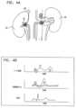
本発明のいくつかの適用例は、概して、医療用装置に関する。詳細には、本発明のいくつかの適用例は、対象の腎静脈の1つまたは複数の中にポンプを設置することに関連付けされる装置および方法に関する。 Some applications of the invention generally relate to medical devices. In particular, some applications of the invention relate to devices and methods associated with placing a pump within one or more of a subject's renal veins.
心機能障害または鬱血性心不全が腎臓機能障害に発展し、そして、それは、鬱血性心不全の症状が発展または悪化することを引き起こすということがよく見られる。典型的に、心臓収縮期のおよび/または心臓拡張期の心機能障害は、全身静脈の鬱血を引き起こし、腎静脈圧力および間質圧力の増加を生じさせる。圧力の増加は、腎臓機能障害および腎臓の神経ホルモン活性化の両方に起因して、身体による体液貯留が増加することを引き起こし、その両方は、典型的に、腎静脈圧力および間質圧力の増加の結果として発展する。結果として生じる体液貯留は、心臓における血液体積の過負荷を引き起こすことによって、および/または、全身抵抗を増加させることによって、鬱血性心不全が発展または悪化することを引き起こす。同様に、腎臓機能障害および/または腎臓の神経ホルモン活性化が、心機能障害および/または鬱血性心不全へ発展するということがよく見られる。この病態生理学的なサイクルでは、心機能障害および/もしくは鬱血性心不全が、腎臓機能障害および/もしくは腎臓の神経ホルモン活性化につながるか、または、腎臓機能障害および/もしくは腎臓の神経ホルモン活性化が、心機能障害および/もしくは鬱血性心不全につながり、それぞれの機能障害が、他の機能障害の悪化につながり、この病態生理学的なサイクルは、心腎臓症候群と呼ばれる。 It is often seen that cardiac dysfunction or congestive heart failure develops into renal dysfunction, which causes the symptoms of congestive heart failure to develop or worsen. Typically, systolic and/or diastolic cardiac dysfunction causes systemic venous congestion, resulting in increased renal venous pressure and interstitial pressure. Increased pressure causes increased fluid retention by the body due to both renal dysfunction and renal neurohormonal activation, both of which typically result in increased renal venous pressure and interstitial pressure. develops as a result of The resulting fluid retention causes congestive heart failure to develop or worsen by causing blood volume overload in the heart and/or by increasing systemic resistance. Similarly, it is frequently seen that renal dysfunction and/or renal neurohormonal activation develops into cardiac dysfunction and/or congestive heart failure. In this pathophysiological cycle, cardiac dysfunction and/or congestive heart failure leads to renal dysfunction and/or renal neurohormonal activation; , leading to cardiac dysfunction and/or congestive heart failure, each dysfunction leading to worsening of the other, and this pathophysiological cycle is called cardiorenal syndrome.
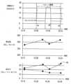
増加した腎静脈圧力は、高窒素血症、ならびに、糸球体ろ過率、腎血流、尿出力、およびナトリウム排泄の低減を引き起こすことが実験的に示されている。また、血漿レニンおよびアルドステロン、ならびにタンパク質排泄を増加させることが示されている。また、静脈性鬱血は、3つの異なる経路、すなわち、腎臓のエリスロポエチン生成の低減、体液貯留による血液希釈、および、胃腸の鉄取り込みを低減されることにつながる炎症反応を介して貧血に寄与する可能性がある。 Increased renal venous pressure has been shown experimentally to cause azotemia and reductions in glomerular filtration rate, renal blood flow, urine output, and sodium excretion. It has also been shown to increase plasma renin and aldosterone, as well as protein excretion. Venous congestion may also contribute to anemia through three different pathways: reduced renal erythropoietin production, hemodilution due to fluid retention, and inflammatory responses that lead to reduced gastrointestinal iron uptake. There is sex.
機構的に、増加した腎静脈圧力は、嚢内圧力、および、その後に、間質尿細管周囲圧力が上昇することを引き起こす可能性がある。尿細管周囲圧力の上昇は、ボーマン嚢の圧力
を上昇させることによって、尿細管機能に影響を与え(ナトリウム排泄を低減させる)、糸球体のろ過を減少させる可能性がある。Mechanistically, increased renal vein pressure can cause intracapsular pressure and, subsequently, increased interstitial peritubular pressure. Increased peritubular pressure can affect tubular function (reducing sodium excretion) and reduce glomerular filtration by increasing Bowman's capsule pressure.
心不全患者において、増加した腎静脈圧力は、増加した中心静脈(右心房)圧力から結果として生じるだけでなく、腎静脈に直接圧力を働かせる腹腔内体液滞留(腹水症)からも結果として生じる可能性がある。(たとえば、穿刺および/または限外ろ過を介する)体液の除去による心不全患者の腹腔内圧力の低減は、血漿クレアチニンレベルを低減させるということが示されている。 In patients with heart failure, increased renal vein pressure can result not only from increased central venous (right atrial) pressure, but also from intra-abdominal fluid retention (ascites), which exerts pressure directly on the renal veins. There is. Reducing intra-abdominal pressure in heart failure patients by removing body fluids (eg, via paracentesis and/or ultrafiltration) has been shown to reduce plasma creatinine levels.
ウォーキングなどのような身体的活動の間の「脚筋ポンプ」の活性化から結果として生じる静脈還流の増加は、とりわけ、心不全患者の全身静脈圧力を上昇させる可能性があり、腎静脈の中への逆流を結果として生じる可能性がある。 The increase in venous return resulting from the activation of the "leg muscle pump" during physical activities such as walking can, among other things, increase systemic venous pressure in patients with heart failure, leading to increased flow into the renal veins. reflux may result.
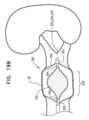
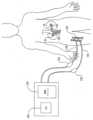
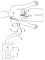
本発明のいくつかの適用例によれば、心機能障害、鬱血性心不全、低腎血流、高腎血管抵抗、動脈性高血圧、および/または腎臓機能障害を患う対象の急性治療を提供するために、インペラーを含む血液ポンプが、対象の腎静脈の内側に設置され、インペラーが、腎静脈から対象の大静脈へ血液をポンピングするように動かされる。たとえば、インペラーは、1時間を超える(たとえば、1日を超える)期間、1週間未満(たとえば、4日未満)の期間、および/または、1時間から1週間の間(たとえば、1日から4日の間)の期間にわたり、対象の腎静脈の内側に設置され得る。 According to some applications of the invention, to provide acute treatment of subjects suffering from cardiac dysfunction, congestive heart failure, low renal blood flow, high renal vascular resistance, arterial hypertension, and/or renal dysfunction. A blood pump containing an impeller is placed inside the subject's renal vein, and the impeller is moved to pump blood from the renal vein to the subject's vena cava. For example, the impeller may operate for a period of time greater than one hour (e.g., more than one day), less than a week (e.g., less than four days), and/or for a period of time between one hour and one week (e.g., one day and four days). It can be placed inside the subject's renal vein for a period of time (during days).
ポンプは、典型的に、下流方向に血液をポンピングし、腎静脈の中の圧力を低減させるように構成されている。典型的に、下流方向への血液のポンピングによって引き起こされる腎静脈の中の圧力の低減に起因して、腎臓のかん流が増加する。そして、これは、腎静脈の中への増加した血液フローに起因して、腎静脈の中の圧力が、ポンピングの始動の直後の腎静脈の中の圧力に対して上昇することを引き起こすことが可能である。典型的に、腎臓のかん流が増加した後でも、ポンプは、腎静脈の中の圧力を、ポンピングの始動の前の腎静脈の中の圧力よりも低い値に維持するように構成されている。 The pump is typically configured to pump blood in a downstream direction and reduce pressure within the renal vein. Typically, renal perfusion increases due to a reduction in pressure within the renal veins caused by pumping blood downstream. And this can cause the pressure in the renal vein to rise relative to the pressure in the renal vein immediately after the start of pumping due to the increased blood flow into the renal vein. It is possible. Typically, even after renal perfusion has increased, the pump is configured to maintain the pressure within the renal vein at a value lower than the pressure within the renal vein prior to initiation of pumping. .
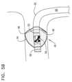
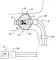
典型的に、対象の腎静脈は、腎静脈の中へインペラーの周りにケージを設置することによって、インペラーによって傷つけられることから保護され、ケージは、腎静脈の壁部をインペラーから分離させる。いくつかの適用例では、ケージおよびインペラーは、係合メカニズムによって互いに係合させられており、ケージが半径方向に圧縮されることに応答して、インペラーが、半径方向に圧縮され、それによって、ケージが、腎静脈の壁部とインペラーとの間の分離を維持するようになっている。 Typically, the subject's renal vein is protected from injury by the impeller by placing a cage around the impeller into the renal vein, the cage separating the wall of the renal vein from the impeller. In some applications, the cage and impeller are engaged with each other by an engagement mechanism such that in response to the cage being radially compressed, the impeller is radially compressed, thereby A cage is adapted to maintain separation between the wall of the renal vein and the impeller.
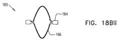
いくつかの適用例によれば、心機能障害、鬱血性心不全、低腎血流、高腎血管抵抗、動脈性高血圧、および/または腎臓機能障害を患う対象の急性治療を提供するために、ポンプおよび閉塞エレメント(たとえば、バルブ)が、対象の腎静脈の内側に設置されている。たとえば、ポンプおよび閉塞エレメントは、1時間を超える(たとえば、1日を超える)期間、1週間未満(たとえば、4日未満)の期間、および/または、1時間から1週間の間(たとえば、1日から4日の間)の期間にわたり、対象の腎静脈の内側に設置され得る。 According to some applications, the pump may be used to provide acute treatment for subjects suffering from cardiac dysfunction, congestive heart failure, low renal blood flow, high renal vascular resistance, arterial hypertension, and/or renal dysfunction. and an occlusion element (eg, a valve) placed inside the subject's renal vein. For example, the pump and occlusion element may be used for a period of more than one hour (e.g., more than one day), less than one week (e.g., less than four days), and/or for a period of one hour to one week (e.g., one day). It can be placed inside the subject's renal vein for a period of time (between days and days).
閉塞エレメントは、閉塞部位において、腎静脈を閉塞させるように構成されている。ポンプは、閉塞エレメントの上流側に流体連通している部位から、閉塞エレメントの下流側に流体連通している部位へ、下流方向に血液をポンピングするように構成されている。そ
うする際に、ポンプは、腎静脈の中の圧力を低減させる。閉塞エレメントは、大静脈から腎静脈への血液のバックフローから腎静脈を保護するように構成されている。The occlusion element is configured to occlude the renal vein at the site of occlusion. The pump is configured to pump blood in a downstream direction from a region in fluid communication upstream of the occlusion element to a region in fluid communication downstream of the occlusion element. In doing so, the pump reduces pressure within the renal veins. The occlusion element is configured to protect the renal vein from backflow of blood from the vena cava to the renal vein.
典型的に、下流方向への血液のポンピングによって引き起こされる腎静脈の中の圧力の低減に起因して、腎臓のかん流が増加する。そして、これは、腎静脈の中への増加した血液フローに起因して、腎静脈の中の圧力が、ポンピングの始動の直後の腎静脈の中の圧力に対して上昇することを引き起こすことが可能である。典型的に、腎臓のかん流が増加した後でも、ポンプは、腎静脈の中の圧力を、ポンピングの始動の前の腎静脈の中の圧力よりも低い値に維持するように構成されている。 Typically, renal perfusion increases due to a reduction in pressure within the renal veins caused by pumping blood downstream. And this can cause the pressure in the renal vein to rise relative to the pressure in the renal vein immediately after the start of pumping due to the increased blood flow into the renal vein. It is possible. Typically, even after renal perfusion has increased, the pump is configured to maintain the pressure in the renal vein at a value lower than the pressure in the renal vein prior to initiation of pumping. .
本発明のいくつかの適用例によれば、血液不浸透性のスリーブは、対象の大静脈の中に設置されており、スリーブの下流端部が、対象のすべての腎静脈下流にある第1の場所において、大静脈の壁部に連結されるようになっており、また、スリーブの上流端部が、対象のすべての腎静脈の上流にある第2の場所において、大静脈の壁部に連結されるようになっている。典型的に、カップリング構造体、たとえば、剛体カップリング構造体(たとえば、ステント)は、スリーブの上流端部および下流端部を大静脈に連結するように構成されている。 According to some applications of the invention, a blood-impermeable sleeve is placed within the subject's vena cava, and the downstream end of the sleeve is located in the first renal vein downstream of all of the subject's vena cava. and the upstream end of the sleeve is adapted to connect to the wall of the vena cava at a second location upstream of all renal veins of interest. It is now connected. Typically, a coupling structure, such as a rigid coupling structure (eg, a stent), is configured to connect the upstream and downstream ends of the sleeve to the vena cava.
ポンプは、スリーブの外部にある場所から、スリーブの内部に流体連通している場所(たとえば、スリーブの上流または下流の大静脈の中の場所)へ、血液をポンピングする。したがって、ポンプは、対象の腎静脈から対象の大静脈の中へ、血液をポンピングする。スリーブは、大静脈から腎静脈の中への血液のバックフローを防止する。 The pump pumps blood from a location external to the sleeve to a location in fluid communication with the interior of the sleeve (eg, a location in the vena cava upstream or downstream of the sleeve). The pump thus pumps blood from the subject's renal vein into the subject's vena cava. The sleeve prevents backflow of blood from the vena cava into the renal veins.
したがって、本発明のいくつかの適用例によれば、
心機能障害、鬱血性心不全、腎血流の低減、腎血管抵抗の増加、動脈性高血圧、および腎臓機能障害からなる群から選択される状態を患うものとして対象を認定するステップと、
それに応答して、対象の腎静脈の内側にインペラーを設置することによって、および、腎静脈から対象の大静脈へ血液をポンピングするようにインペラーを動かすことによって、対象の腎静脈の中の血圧を低減させるステップと、
を含む、方法が提供される。Therefore, according to some applications of the invention:
identifying the subject as suffering from a condition selected from the group consisting of cardiac dysfunction, congestive heart failure, reduced renal blood flow, increased renal vascular resistance, arterial hypertension, and renal dysfunction;
In response, the blood pressure within the subject's renal vein is reduced by placing an impeller inside the subject's renal vein and moving the impeller to pump blood from the renal vein to the subject's vena cava. a step of reducing;
A method is provided, including.
いくつかの適用例では、腎静脈から大静脈の中へ血液をポンピングするようにインペラーを動かすステップは、ポンプを動かすことがない場合の腎静脈から大静脈の中への血液フローの方向と比較して、血液フローの方向の実質的な変化を引き起こすことなく、腎静脈から大静脈の中への血液フローのレートを強化するステップを含む。 In some applications, moving the impeller to pump blood from the renal vein into the vena cava may be compared to the direction of blood flow from the renal vein into the vena cava without moving the pump. to enhance the rate of blood flow from the renal vein into the vena cava without causing a substantial change in the direction of blood flow.
いくつかの適用例では、腎静脈から大静脈の中へ血液をポンピングするようにインペラーを動かすステップは、腎静脈から、腎静脈に隣接している大静脈の一部分の中へ、直接的に血液をポンピングするように、インペラーを動かすステップを含む。 In some applications, moving the impeller to pump blood from the renal vein into the vena cava may include pumping blood directly from the renal vein into a portion of the vena cava adjacent to the renal vein. including the step of moving an impeller to pump.
いくつかの適用例では、腎静脈から大静脈の中へ血液をポンピングするようにインペラーを動かすステップは、対象の静脈系から、静脈でないレセプタクルの中へ、血液を除去することなく、腎静脈から大静脈の中へ血液をポンピングするようにインペラーを動かすステップを含む。 In some applications, moving the impeller to pump blood from the renal vein into the vena cava may include removing blood from the renal vein from the subject's venous system into a nonvenous receptacle. including moving an impeller to pump blood into the vena cava.
いくつかの適用例では、腎静脈の内側にインペラーを設置するステップは、ケージがインペラーの周りに配設され、ケージが腎静脈の内側壁部をインペラーから分離させている状態で、腎静脈の中へインペラーを設置することによって、対象の腎静脈がインペラーによって傷つけられることを保護するステップを含む。 In some applications, placing the impeller inside the renal vein involves placing the impeller inside the renal vein, with the cage placed around the impeller and the cage separating the inside wall of the renal vein from the impeller. protecting the subject's renal vein from injury by the impeller by placing the impeller therein;
いくつかの適用例では、ケージがインペラーの周りに配設されている状態で、腎静脈の中へインペラーを設置するステップは、ケージがインペラーの周りに配設されている状態で、腎静脈の中へインペラーを設置するステップであって、ケージおよびインペラーは、係合メカニズムによって互いに係合されており、ケージが半径方向に圧縮されることに応答して、インペラーが軸線方向に長くされるようになっており、ケージが、腎静脈の壁部とインペラーとの間の分離を維持するようになっている、ステップを含む。 In some applications, placing the impeller into the renal vein with the cage disposed about the impeller includes placing the impeller into the renal vein with the cage disposed about the impeller. installing an impeller therein, the cage and impeller being engaged with each other by an engagement mechanism such that the impeller is lengthened axially in response to radial compression of the cage; and the cage includes a step adapted to maintain separation between the wall of the renal vein and the impeller.
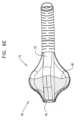
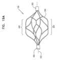
本発明のいくつかの適用例によれば、インペラーを含む装置であって、インペラーは、
近位端部部分および遠位端部部分、ならびに、近位端部部分から遠位端部部分へ曲がって進む複数のらせん状の細長いエレメントを含むインペラーフレームと、
材料であって、材料は、らせん状の細長いエレメントに連結されており、材料がそれに連結されているらせん状の細長いエレメントが、インペラーの少なくとも1つのブレードを画定するようになっている、材料と
を含む、装置がさらに提供される。According to some applications of the invention, an apparatus includes an impeller, the impeller comprising:
an impeller frame including a proximal end portion and a distal end portion and a plurality of helical elongated elements winding from the proximal end portion to the distal end portion;
a material, the material being connected to a helical elongate element such that the helical elongate element to which the material is connected defines at least one blade of an impeller; Further provided is an apparatus comprising:
いくつかの適用例では、インペラーが、対象の血管の中へ挿入されるように構成されている生体適合性インペラーを含む。 In some applications, the impeller includes a biocompatible impeller configured to be inserted into a blood vessel of a subject.
いくつかの適用例では、複数の細長いエレメントが、複数のらせん状のストリップを含む。 In some applications, the plurality of elongated elements includes a plurality of helical strips.
いくつかの適用例では、らせん状の細長いエレメントの少なくとも1つが、可変のピッチを有しており、細長いエレメントの少なくとも1つのピッチは、らせん状の細長いエレメントの長さに沿って変化している。 In some applications, at least one of the helical elongate elements has a variable pitch, and the pitch of at least one of the elongate elements varies along the length of the helical elongate element. .
いくつかの適用例では、インペラーは、対象の血管の内側に設置されるように、および、血管に対して回転させることによって、血管を通して血液をポンピングするように構成されており、装置が、半径方向に拡張可能なケージをさらに含み、半径方向に拡張可能なケージは、インペラーと血管の内側壁部との間に配設されるように、および、血管壁部をインペラーから分離させるように構成されている。 In some applications, the impeller is configured to pump blood through the blood vessel by being placed inside the target blood vessel and rotating relative to the blood vessel, such that the device has a radius further comprising a radially expandable cage, the radially expandable cage configured to be disposed between the impeller and the inner wall of the blood vessel and to separate the blood vessel wall from the impeller. has been done.
いくつかの適用例では、近位端部部分および遠位端部部分が、近位リングおよび遠位リングを含む。 In some applications, the proximal end portion and the distal end portion include a proximal ring and a distal ring.
いくつかの適用例では、近位端部部分および遠位端部部分のうちの少なくとも1つが、その縁部に切り欠き部を画定しており、切り欠き部は、らせん状の細長いエレメントへの材料の連結を促進させるように構成されている。 In some applications, at least one of the proximal end portion and the distal end portion defines a notch in an edge thereof, the notch defining a cutout to the helical elongate element. Configured to promote bonding of materials.
いくつかの適用例では、インペラーが、らせん状の細長いエレメントの周りに結合された縫合糸をさらに含み、縫合糸は、らせん状の細長いエレメントへの材料の連結を促進させるように構成されている。 In some applications, the impeller further includes a suture coupled around the helical elongate element, the suture configured to facilitate coupling of material to the helical elongate element. .
いくつかの適用例では、複数のらせん状の細長いエレメントが、近位端部部分から遠位端部部分へ曲がって進む3つのらせん状の細長いエレメントを含む。 In some applications, the plurality of helical elongate elements includes three helical elongate elements winding from a proximal end portion to a distal end portion.
いくつかの適用例では、インペラーがその拘束されていない構成になっているときに、インペラーの長手方向軸線に沿って測定される、らせん状の細長いエレメントのそれぞれの長さが、5mmよりも大きい。いくつかの適用例では、インペラーがその拘束されていない構成になっているときに、インペラーの長手方向軸線に沿って測定される、らせん状
の細長いエレメントのそれぞれの長さが、14mmよりも小さい。In some applications, the length of each of the helical elongate elements, measured along the longitudinal axis of the impeller when the impeller is in its unconstrained configuration, is greater than 5 mm. . In some applications, the length of each of the helical elongate elements, measured along the longitudinal axis of the impeller when the impeller is in its unconstrained configuration, is less than 14 mm. .
いくつかの適用例では、インペラーがその拘束されていない構成になっているときに、インペラーの長手方向軸線に対して垂直の方向のインペラーのスパンが、8mmよりも大きい。いくつかの適用例では、インペラーのスパンが、10mmよりも大きい。いくつかの適用例では、インペラーのスパンが、15mmよりも小さい。いくつかの適用例では、インペラーのスパンが、12mmよりも小さい。 In some applications, the span of the impeller in a direction perpendicular to the longitudinal axis of the impeller is greater than 8 mm when the impeller is in its unconstrained configuration. In some applications, the span of the impeller is greater than 10 mm. In some applications, the span of the impeller is less than 15 mm. In some applications, the span of the impeller is less than 12 mm.
いくつかの適用例では、複数のらせん状の細長いエレメントが、近位端部部分から遠位端部部分へ曲がって進む2つのらせん状の細長いエレメントを含む。 In some applications, the plurality of helical elongate elements includes two helical elongate elements winding from a proximal end portion to a distal end portion.
いくつかの適用例では、2つのらせん状の細長いエレメントのそれぞれの半径が、互いの20パーセント以内である。いくつかの適用例では、2つのらせん状の細長いエレメントのそれぞれの半径が、互いに同様である。いくつかの適用例では、2つのらせん状の細長いエレメントのそれぞれのピッチが、互いの20パーセント以内である。いくつかの適用例では、2つのらせん状の細長いエレメントのそれぞれのピッチが、互いに同様である。いくつかの適用例では、2つのらせん状の細長いエレメントのそれぞれの長手方向の軸線が、互いに平行になっており、かつ、インペラーの長手方向軸線に対して平行になっている。 In some applications, the radii of each of the two helical elongate elements are within 20 percent of each other. In some applications, the radii of each of the two helical elongate elements are similar to each other. In some applications, the pitch of each of the two helical elongate elements is within 20 percent of each other. In some applications, the pitch of each of the two helical elongate elements is similar to each other. In some applications, the respective longitudinal axes of the two helical elongate elements are parallel to each other and parallel to the longitudinal axis of the impeller.
いくつかの適用例では、材料が、らせん状の細長いエレメントによって支持されている材料の連続的なフィルムを含む。 In some applications, the material comprises a continuous film of material supported by helical elongated elements.
いくつかの適用例では、らせん状の細長いエレメントのそれぞれが、らせんの巻線の8分の1以上を画定している。いくつかの適用例では、らせん状の細長いエレメントのそれぞれが、らせんの巻線の半分未満を画定している。 In some applications, each of the helical elongate elements defines one-eighth or more of the windings of the helix. In some applications, each of the helical elongate elements defines less than half of the windings of the helix.
いくつかの適用例では、
らせん状の細長いエレメントが、その近位端部および遠位端部を画定しており、らせん状の細長いエレメントは、らせん状の細長いエレメントの近位端部と遠位端部との間に材料を支持するように構成されており、
インペラーは、らせん状の細長いエレメントの近位端部と遠位端部との間に材料を支持するための追加的な支持部材を含んでいない。In some applications,
A helical elongate element defines proximal and distal ends thereof, and the helical elongate element has a material disposed between the proximal and distal ends of the helical elongate element. is configured to support
The impeller does not include additional support members for supporting material between the proximal and distal ends of the helical elongated element.
いくつかの適用例では、実質的にインペラーのらせん状の細長いエレメントだけを介して、インペラーの近位端部部分からインペラーの遠位端部部分へ、回転運動が与えられるように、インペラーが構成されている。 In some applications, the impeller is configured such that rotational motion is imparted from a proximal end portion of the impeller to a distal end portion of the impeller substantially solely through the helical elongated element of the impeller. has been done.
いくつかの適用例では、らせん状の細長いエレメントの近位端部と遠位端部との間に、材料を支持するための追加的な支持部材を含まないことによって、インペラーは、インペラーがらせん状の細長いエレメントの近位端部と遠位端部との間に材料を支持するための追加的な支持部材を含んだとした場合よりも小さい直径まで、半径方向に圧縮可能であるように構成されている。 In some applications, the impeller is configured such that the impeller does not include an additional support member between the proximal and distal ends of the helical elongated element to support the material. radially compressible to a smaller diameter than if it had included an additional support member for supporting the material between the proximal and distal ends of the elongated element; It is configured.
いくつかの適用例では、らせん状の細長いエレメントの近位端部と遠位端部との間に、材料を支持するための追加的な支持部材を含まないことによって、インペラーは、インペラーがらせん状の細長いエレメントの近位端部と遠位端部との間に材料を支持するための追加的な支持部材を含んだとした場合よりも柔軟性があるように構成されている。 In some applications, the impeller is configured such that the impeller does not include an additional support member between the proximal and distal ends of the helical elongated element to support the material. The elongated element is configured to be more flexible than it would be if it included an additional support member for supporting the material between the proximal and distal ends of the elongated element.
いくつかの適用例では、らせん状の細長いエレメントの近位端部と遠位端部との間に、
材料を支持するための追加的な支持部材を含まないことによって、インペラーを軸線方向に長くするために必要とされる力が、インペラーがらせん状の細長いエレメントの近位端部と遠位端部との間に材料を支持するための追加的な支持部材を含んだとした場合に必要とされることとなるものよりも所定の量だけ小さくなるように、インペラーが構成されている。In some applications, between the proximal and distal ends of the helical elongated element,
By not including additional support members to support the material, the force required to lengthen the impeller axially is reduced by the force required to lengthen the impeller axially at the proximal and distal ends of the helical elongated element. The impeller is configured to be a predetermined amount smaller than would be required if additional support members were included to support the material between the impeller and the impeller.
本発明のいくつかの適用例によれば、
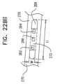
切断チューブが構造体の近位端部および遠位端部において第1および第2の端部部分を有する構造体を画定するように、チューブを切断するステップであって、端部部分は、複数の細長いエレメントによって互いに接続されている、ステップと、
構造体を軸線方向に圧縮することによって、細長いエレメントが半径方向に拡張し、らせん状の細長いエレメントを形成することを引き起こすステップと、
材料がそれに連結されているらせん状の細長いエレメントが、インペラーの少なくとも1つのブレードを画定するように、らせん状の細長いエレメントに材料を連結するステップと
によって、インペラーを製造するステップを含む、方法が追加的に提供される。According to some applications of the invention:
cutting the tube such that the cut tube defines a structure having first and second end portions at a proximal end and a distal end of the structure, the end portions having a plurality of end portions; steps connected to each other by elongated elements of
axially compressing the structure causing the elongate element to expand radially to form a helical elongate element;
connecting a material to a helical elongate element such that the helical elongate element to which the material is connected defines at least one blade of the impeller. additionally provided.
いくつかの適用例では、チューブを切断するステップは、チューブをレーザー切断するステップを含む。 For some applications, cutting the tube includes laser cutting the tube.
いくつかの適用例では、インペラーを製造するステップは、対象の血管の中へ挿入されるように構成されている生体適合性インペラーを製造するステップを含む。 For some applications, manufacturing an impeller includes manufacturing a biocompatible impeller that is configured to be inserted into a blood vessel of a subject.
いくつかの適用例では、チューブを切断するステップは、切断チューブが構造体の近位端部および遠位端部において第1および第2の端部部分を有する構造体を画定するように、チューブを切断するステップであって、端部部分は、複数のストリップによって互いに接続されている、ステップを含む。 In some applications, cutting the tube includes cutting the tube such that the cut tube defines a structure having first and second end portions at a proximal end and a distal end of the structure. cutting the end portions, the end portions being connected to each other by a plurality of strips.
いくつかの適用例では、細長いエレメントが半径方向に拡張し、らせん状の細長いエレメントを形成することを引き起こすステップは、らせん状の細長いエレメントの少なくとも1つが、可変のピッチを有することを引き起こすステップであって、細長いエレメントの少なくとも1つのピッチが、らせん状の細長いエレメントの長さに沿って変化する、ステップを含む。 In some applications, causing the elongate elements to expand radially to form a helical elongate element includes causing at least one of the helical elongate elements to have a variable pitch. The pitch of at least one of the elongate elements varies along the length of the helical elongate element.
いくつかの適用例では、切断チューブが構造体の近位端部および遠位端部において第1および第2の端部部分を有する構造体を画定するように、チューブを切断するステップは、切断チューブが構造体の近位端部および遠位端部において第1および第2のリングを有する構造体を画定するように、チューブを切断するステップを含む。 In some applications, cutting the tube includes cutting the tube such that the cutting tube defines a structure having first and second end portions at a proximal end and a distal end of the structure. cutting the tube such that the tube defines a structure having first and second rings at a proximal end and a distal end of the structure.
いくつかの適用例では、チューブを切断するステップは、端部部分の少なくとも1つの縁部に切り欠き部を形成するステップであって、切り欠き部は、らせん状の細長いエレメントへの材料の連結を促進させるように構成されている、ステップをさらに含む。 In some applications, cutting the tube includes forming a notch in at least one edge of the end portion, the notch connecting the material to the helical elongated element. further comprising steps configured to facilitate.
いくつかの適用例では、方法が、らせん状の細長いエレメントの周りに縫合糸を結合するステップであって、縫合糸は、らせん状の細長いエレメントへの材料の連結を促進させるように構成されている、ステップをさらに含む。 In some applications, the method includes coupling a suture around a helical elongate element, the suture being configured to facilitate coupling of material to the helical elongate element. further steps.
いくつかの適用例では、チューブを切断するステップは、切断チューブが構造体の近位端部および遠位端部において第1および第2の端部部分を有する構造体を画定するように、チューブを切断するステップであって、端部部分は、3つの細長いエレメントによって互いに接続されている、ステップを含み、細長いエレメントが半径方向に拡張し、らせん状の細長いエレメントを形成することを引き起こすステップは、細長いエレメントが3つのらせん状の細長いエレメントを形成することを引き起こすステップを含む。 In some applications, cutting the tube includes cutting the tube such that the cut tube defines a structure having first and second end portions at a proximal end and a distal end of the structure. the step of cutting, the end portions being connected to each other by three elongate elements, the step of causing the elongate elements to expand radially to form a helical elongate element; , causing the elongate elements to form three helical elongate elements.
いくつかの適用例では、チューブを切断するステップは、構造体に加えられている軸線方向の圧縮がない場合に、構造体が、構造体の長手方向軸線に沿って測定される、15mmよりも大きい長さを有するように、チューブを切断するステップを含む。いくつかの適用例では、チューブを切断するステップは、構造体に加えられている軸線方向の圧縮がない場合に、構造体の長手方向軸線に沿って測定される、構造体の長さが、25mmよりも小さくなるように、チューブを切断するステップを含む。いくつかの適用例では、チューブを切断するステップは、構造体に加えられている軸線方向の圧縮がない場合に、細長いエレメントのそれぞれが、構造体の長手方向軸線に沿って測定される、14mmよりも大きい長さを有するように、チューブを切断するステップを含む。いくつかの適用例では、チューブを切断するステップは、構造体に加えられている軸線方向の圧縮がない場合に、構造体の長手方向軸線に沿って測定される、細長いエレメントのそれぞれの長さが、22mmよりも小さくなるように、チューブを切断するステップを含む。 In some applications, cutting the tube may include cutting the tube if the structure is larger than 15 mm, measured along the longitudinal axis of the structure, in the absence of axial compression being applied to the structure. cutting the tube to have a larger length; In some applications, the step of cutting the tube includes the length of the structure, measured along the longitudinal axis of the structure, in the absence of axial compression being applied to the structure. cutting the tube to be smaller than 25 mm; In some applications, cutting the tube includes cutting the tube so that each of the elongated elements has a length of 14 mm, measured along the longitudinal axis of the structure, in the absence of axial compression being applied to the structure. cutting the tube to have a length greater than the length of the tube. In some applications, cutting the tube includes cutting the length of each elongated element as measured along the longitudinal axis of the structure in the absence of axial compression being applied to the structure. cutting the tube so that it is smaller than 22 mm.
いくつかの適用例では、構造体を軸線方向に圧縮するステップは、構造体が、構造体の長手方向軸線に沿って測定される、8mmよりも大きい長さを画定するように、構造体を軸線方向に圧縮するステップを含む。いくつかの適用例では、構造体を軸線方向に圧縮するステップは、構造体の長手方向軸線に沿って測定される長さが、18mmよりも小さくなるように、構造体を軸線方向に圧縮するステップを含む。いくつかの適用例では、構造体を軸線方向に圧縮するステップは、細長いエレメントのそれぞれが、構造体の長手方向軸線に沿って測定される、5mmよりも大きい長さを画定するように、構造体を軸線方向に圧縮するステップを含む。いくつかの適用例では、構造体を軸線方向に圧縮するステップは、構造体の長手方向軸線に沿って測定される、細長いエレメントのそれぞれの長さが、14mmよりも小さくなるように、構造体を軸線方向に圧縮するステップを含む。 In some applications, axially compressing the structure includes compressing the structure such that the structure defines a length greater than 8 mm, measured along the longitudinal axis of the structure. axially compressing. In some applications, axially compressing the structure includes axially compressing the structure such that the length measured along the longitudinal axis of the structure is less than 18 mm. Contains steps. In some applications, axially compressing the structure includes compressing the structure such that each of the elongated elements defines a length greater than 5 mm, measured along the longitudinal axis of the structure. axially compressing the body. In some applications, axially compressing the structure includes compressing the structure such that the length of each elongate element, measured along the longitudinal axis of the structure, is less than 14 mm. axially compressing the.
いくつかの適用例では、構造体を軸線方向に圧縮するステップは、構造体の長手方向軸線に対して垂直の方向の構造体のスパンが、8mmよりも大きくなるように、構造体を軸線方向に圧縮するステップを含む。いくつかの適用例では、構造体を軸線方向に圧縮するステップは、構造体のスパンが、10mmよりも大きくなるように、構造体を軸線方向に圧縮するステップを含む。いくつかの適用例では、構造体を軸線方向に圧縮するステップは、構造体のスパンが、15mmよりも小さくなるように、構造体を軸線方向に圧縮するステップを含む。いくつかの適用例では、構造体を軸線方向に圧縮するステップは、構造体のスパンが、12mmよりも小さくなるように、構造体を軸線方向に圧縮するステップを含む。 In some applications, axially compressing the structure includes axially compressing the structure such that the span of the structure perpendicular to the longitudinal axis of the structure is greater than 8 mm. including the step of compressing it into For some applications, axially compressing the structure includes axially compressing the structure such that the span of the structure is greater than 10 mm. For some applications, axially compressing the structure includes axially compressing the structure such that the span of the structure is less than 15 mm. For some applications, axially compressing the structure includes axially compressing the structure such that the span of the structure is less than 12 mm.
いくつかの適用例では、らせん状の細長いエレメントに材料を連結するステップは、材料がその液体状態にある間に、構造体の少なくとも一部分を材料の中へ浸漬させるステップと、材料がらせん状の細長いエレメントによって支持されている間に、材料を乾燥させるステップとを含む。いくつかの適用例では、材料を乾燥させるステップは、材料を硬化させるステップを含む。 In some applications, coupling the material to the helical elongate element includes immersing at least a portion of the structure into the material while the material is in its liquid state; drying the material while supported by the elongate element. For some applications, drying the material includes curing the material.
いくつかの適用例では、チューブを切断するステップは、切断チューブが構造体の近位端部および遠位端部において第1および第2の端部部分を有する構造体を画定するように、チューブを切断するステップであって、端部部分は、2つの細長いエレメントによって互いに接続されている、ステップを含み、細長いエレメントが半径方向に拡張し、らせん状の細長いエレメントを形成することを引き起こすステップは、細長いエレメントが2つのらせん状の細長いエレメントを形成することを引き起こすステップを含む。 In some applications, cutting the tube includes cutting the tube such that the cut tube defines a structure having first and second end portions at a proximal end and a distal end of the structure. , the end portions being connected to each other by two elongated elements, the step of causing the elongated elements to expand radially to form a helical elongated element. , causing the elongate element to form two helical elongate elements.
いくつかの適用例では、材料がらせん状の細長いエレメントによって支持されている間に液体材料を乾燥させるステップは、材料がらせん状の細長いエレメント同士の間に連続的なフィルムを形成することを引き起こすステップであって、連続的なフィルムは、らせん状の細長いエレメントによって支持されている、ステップを含む。 In some applications, drying the liquid material while the material is supported by the helical elongate elements causes the material to form a continuous film between the helical elongate elements. The step includes a continuous film supported by a helical elongate element.
いくつかの適用例では、チューブを切断するステップは、切断チューブが構造体の近位端部および遠位端部において第1および第2の端部部分を有する構造体を画定するように、チューブを切断するステップであって、端部部分は、2つの細長いエレメントによって互いに接続されている、ステップを含み、細長いエレメントが半径方向に拡張し、らせん状の細長いエレメントを形成することを引き起こすステップは、細長いエレメントが2つのらせん状の細長いエレメントを形成することを引き起こすステップを含む。 In some applications, cutting the tube includes cutting the tube such that the cut tube defines a structure having first and second end portions at a proximal end and a distal end of the structure. , the end portions being connected to each other by two elongated elements, the step of causing the elongated elements to expand radially to form a helical elongated element. , causing the elongate element to form two helical elongate elements.
いくつかの適用例では、細長いエレメントが2つのらせん状の細長いエレメントを形成することを引き起こすステップは、細長いエレメントが2つのらせん状の細長いエレメントを形成することを引き起こすステップであって、2つのらせん状の細長いエレメントの両方が、第1の端部部分から生じ、第2の端部部分において終端しており、らせん状の細長いエレメントの半径は、互いに同様である、ステップを含む。いくつかの適用例では、細長いエレメントが2つのらせん状の細長いエレメントを形成することを引き起こすステップは、細長いエレメントが2つのらせん状の細長いエレメントを形成することを引き起こすステップであって、2つのらせん状の細長いエレメントの両方が、第1の端部部分から生じ、第2の端部部分において終端しており、らせん状の細長いエレメントの半径は、互いの20パーセント以内である、ステップを含む。 In some applications, causing the elongate element to form two helical elongate elements includes causing the elongate element to form two helical elongate elements, the step of causing the elongate element to form two helical elongate elements, Both of the helical elongate elements include steps originating from a first end portion and terminating in a second end portion, the radii of the helical elongate elements being similar to each other. In some applications, causing the elongate element to form two helical elongate elements includes causing the elongate element to form two helical elongate elements, the step of causing the elongate element to form two helical elongate elements, Both of the helical elongate elements include steps originating from a first end portion and terminating in a second end portion, the radii of the helical elongate elements being within 20 percent of each other.
いくつかの適用例では、細長いエレメントが2つのらせん状の細長いエレメントを形成することを引き起こすステップは、細長いエレメントが2つのらせん状の細長いエレメントを形成することを引き起こすステップであって、2つのらせん状の細長いエレメントの両方が、第1の端部部分から生じ、第2の端部部分において終端しており、らせん状の細長いエレメントのピッチは、互いに同様である、ステップを含む。いくつかの適用例では、細長いエレメントが2つのらせん状の細長いエレメントを形成することを引き起こすステップは、細長いエレメントが2つのらせん状の細長いエレメントを形成することを引き起こすステップであって、2つのらせん状の細長いエレメントの両方が、第1の端部部分から生じ、第2の端部部分において終端しており、らせん状の細長いエレメントのピッチは、互いの20パーセント以内である、ステップを含む。 In some applications, causing the elongate element to form two helical elongate elements includes causing the elongate element to form two helical elongate elements, the step of causing the elongate element to form two helical elongate elements, Both of the helical elongate elements emanate from the first end portion and terminate in the second end portion, the pitch of the helical elongate elements being similar to each other. In some applications, causing the elongate element to form two helical elongate elements includes causing the elongate element to form two helical elongate elements, the step of causing the elongate element to form two helical elongate elements, Both of the helical elongate elements emanate from the first end portion and terminate in the second end portion, the pitches of the helical elongate elements being within 20 percent of each other.
いくつかの適用例では、細長いエレメントが2つのらせん状の細長いエレメントを形成することを引き起こすステップは、細長いエレメントが2つのらせん状の細長いエレメントを形成することを引き起こすステップであって、らせん状の細長いエレメントの両方の長手方向の軸線は、互いに平行になっており、かつ、インペラーの長手方向軸線に対して平行になっている、ステップを含む。 In some applications, causing the elongate element to form two helical elongate elements includes causing the elongate element to form two helical elongate elements, the step of causing the elongate element to form two helical elongate elements, Both longitudinal axes of the elongated element include steps that are parallel to each other and parallel to the longitudinal axis of the impeller.
いくつかの適用例では、細長いエレメントが2つのらせん状の細長いエレメントを形成することを引き起こすステップは、細長いエレメントが2つのらせん状の細長いエレメントを形成することを引き起こすステップであって、らせん状の細長いエレメントのそれぞれが、らせんの巻線の8分の1以上を画定している、ステップを含む。いくつかの適用例では、細長いエレメントが2つのらせん状の細長いエレメントを形成することを引き起こすステップは、細長いエレメントが2つのらせん状の細長いエレメントを形成することを引き起こすステップであって、らせん状の細長いエレメントのそれぞれが、らせんの巻線の半分未満を画定している、ステップを含む。 In some applications, causing the elongate element to form two helical elongate elements includes causing the elongate element to form two helical elongate elements, the step of causing the elongate element to form two helical elongate elements, Each of the elongated elements includes a step defining one-eighth or more of the windings of the helix. In some applications, causing the elongate element to form two helical elongate elements includes causing the elongate element to form two helical elongate elements, the step of causing the elongate element to form two helical elongate elements, Each elongated element includes a step defining less than half of the windings of the helix.
いくつかの適用例では、チューブを切断するステップは、切断チューブが構造体の近位端部および遠位端部において第1および第2のリングを有する構造体を画定するように、ならびに、細長いエレメントのそれぞれの第1および第2の端部が、リングの周囲部に関して互いからある角度で配設されるように、チューブを切断するステップであって、角度は、50度よりも大きい、ステップを含む。いくつかの適用例では、チューブを切断するステップは、細長いエレメントのそれぞれの第1および第2の端部が、リングの周囲部に関して互いからある角度で配設されるように、チューブを切断するステップであって、角度は、70度よりも大きい、ステップを含む。いくつかの適用例では、チューブを切断するステップは、細長いエレメントのそれぞれの第1および第2の端部が、リングの周囲部に関して互いからある角度で配設されるように、チューブを切断するステップであって、角度は、90度よりも大きい、ステップを含む。 In some applications, cutting the tube includes an elongated tube such that the cut tube defines a structure having first and second rings at a proximal end and a distal end of the structure. cutting the tube such that the respective first and second ends of the elements are disposed at an angle from each other with respect to the periphery of the ring, the angle being greater than 50 degrees; including. In some applications, cutting the tube includes cutting the tube such that the first and second ends of each of the elongated elements are disposed at an angle from each other with respect to the perimeter of the ring. The step includes a step where the angle is greater than 70 degrees. In some applications, cutting the tube includes cutting the tube such that the first and second ends of each of the elongated elements are disposed at an angle from each other with respect to the perimeter of the ring. The step includes a step where the angle is greater than 90 degrees.
いくつかの適用例では、チューブを切断するステップは、切断チューブが構造体の近位端部および遠位端部において第1および第2のリングを有する構造体を画定するように、ならびに、細長いエレメントのそれぞれの第1および第2の端部が、リングの周囲部に関して互いからある角度で配設されるように、チューブを切断するステップであって、角度は、180度よりも小さい、ステップを含む。いくつかの適用例では、チューブを切断するステップは、細長いエレメントのそれぞれの第1および第2の端部が、リングの周囲部に関して互いからある角度で配設されるように、チューブを切断するステップであって、角度は、150度よりも小さい、ステップを含む。いくつかの適用例では、チューブを切断するステップは、細長いエレメントのそれぞれの第1および第2の端部が、リングの周囲部に関して互いからある角度で配設されるように、チューブを切断するステップであって、角度は、110度よりも小さい、ステップを含む。 In some applications, cutting the tube includes an elongated tube such that the cut tube defines a structure having first and second rings at a proximal end and a distal end of the structure. cutting the tube such that the respective first and second ends of the elements are disposed at an angle from each other with respect to the periphery of the ring, the angle being less than 180 degrees; including. In some applications, cutting the tube includes cutting the tube such that the first and second ends of each of the elongated elements are disposed at an angle from each other with respect to the perimeter of the ring. The angle includes steps that are less than 150 degrees. In some applications, cutting the tube includes cutting the tube such that the first and second ends of each of the elongated elements are disposed at an angle from each other with respect to the perimeter of the ring. The angle includes steps that are less than 110 degrees.
いくつかの適用例では、らせん状の細長いエレメントに材料を連結するステップは、らせん状の細長いエレメントの近位端部と遠位端部との間に材料を支持するための追加的な支持部材がない場合に、らせん状の細長いエレメントの近位端部と遠位端部との間に、材料が、らせん状の細長いエレメントによって支持されるように、細長いエレメントに材料を連結するステップを含む。 In some applications, coupling the material to the helical elongate element includes an additional support member to support the material between the proximal and distal ends of the helical elongate element. coupling the material to the helical elongate element such that the material is supported by the helical elongate element between the proximal and distal ends of the helical elongate element if not present; .
いくつかの適用例では、らせん状の細長いエレメントの近位端部と遠位端部との間に材料を支持するための追加的な支持部材がない場合に、らせん状の細長いエレメントに材料を連結するステップは、実質的にインペラーのらせん状の細長いエレメントだけを介して、近位端部部分から遠位端部部分へ回転運動が与えられるように、インペラーを構成させるステップを含む。 In some applications, material is applied to the helical elongate element when there is no additional support member to support the material between the proximal and distal ends of the helical elongate element. The step of coupling includes configuring the impeller such that rotational movement is imparted from the proximal end portion to the distal end portion substantially solely through the helical elongate element of the impeller.
いくつかの適用例では、らせん状の細長いエレメントの近位端部と遠位端部との間に材料を支持するための追加的な支持部材がない場合に、らせん状の細長いエレメントに材料を連結するステップは、インペラーがらせん状の細長いエレメントの近位端部と遠位端部との間に材料を支持するための追加的な支持部材を含んだとした場合よりも小さい直径まで半径方向に圧縮可能となるように、インペラーを構成させるステップを含む。 In some applications, material is applied to the helical elongate element when there is no additional support member to support the material between the proximal and distal ends of the helical elongate element. The step of coupling includes radially connecting the helical elongate element to a smaller diameter than it would be if the impeller included an additional support member for supporting the material between the proximal and distal ends of the helical elongated element. configuring the impeller so that it can be compressed.
いくつかの適用例では、らせん状の細長いエレメントの近位端部と遠位端部との間に材料を支持するための追加的な支持部材がない場合に、らせん状の細長いエレメントに材料を連結するステップは、インペラーがらせん状の細長いエレメントの近位端部と遠位端部との間に材料を支持するための追加的な支持部材を含んだとした場合よりも柔軟性があるように、インペラーを構成させるステップを含む。 In some applications, material is applied to the helical elongate element when there is no additional support member to support the material between the proximal and distal ends of the helical elongate element. The coupling step may be more flexible than if the impeller included an additional support member for supporting the material between the proximal and distal ends of the helical elongate element. configuring the impeller.
いくつかの適用例では、らせん状の細長いエレメントの近位端部と遠位端部との間に材料を支持するための追加的な支持部材がない場合に、らせん状の細長いエレメントに材料
を連結するステップは、インペラーを軸線方向に長くするために必要とされる力が、インペラーがらせん状の細長いエレメントの近位端部と遠位端部との間に材料を支持するための追加的な支持部材を含んだとした場合に必要とされることとなるものよりも所定の量だけ小さくなるように、インペラーを構成させるステップを含む。In some applications, material is applied to the helical elongate element when there is no additional support member to support the material between the proximal and distal ends of the helical elongate element. The coupling step is such that the force required to lengthen the impeller axially is such that the force required to axially lengthen the impeller is such that the impeller has additional support for material between the proximal and distal ends of the helical elongate element. configuring the impeller to be a predetermined amount smaller than would be required if it included a support member.
本発明のいくつかの適用例によれば、
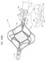
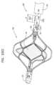
半径方向に拡張させられた構成において、回転することによって、流体をポンピングするように構成されているインペラーと、
インペラーの周りに配設されている半径方向に拡張可能なケージであって、インペラーおよびケージの半径方向に拡張させられた構成において、インペラーが、ケージの内側表面から分離されるようになっている、ケージと、
インペラーをケージに係合させるように構成されている係合メカニズムであって、ケージが半径方向に圧縮されることに応答して、係合メカニズムが、インペラーを軸線方向に長くし、インペラーがケージの内側表面から分離されたままになるようになっている、係合メカニズムと
を含む、装置がさらに提供される。According to some applications of the invention:
an impeller configured to pump fluid by rotating in a radially expanded configuration;
a radially expandable cage disposed about an impeller, the impeller being separated from an inner surface of the cage in a radially expanded configuration of the impeller and cage; , cage, and
an engagement mechanism configured to engage the impeller with the cage, the engagement mechanism axially elongating the impeller in response to radial compression of the cage; and an engagement mechanism adapted to remain separated from the inner surface of the apparatus.
いくつかの適用例では、
ケージおよびインペラーが、その軸線方向に長くされた構成を画定しており、ケージは、その軸線方向に長くされた構成になっている間に、ケージの内側にインペラーを収容するように構成されており、一方、インペラーは、その軸線方向に長くされた構成になっており、
ケージは、支柱を含み、支柱の少なくともいくつかは、少なくともケージがケージの半径方向に拡張させられた構成になっているときに、波状になっている支柱の一部分を含み、
ケージが半径方向に拡張させられた構成になっているときの支柱の波状部分の波打ちのレベルは、ケージがその軸線方向に長くされた構成になっているときの支柱の波状部分の波打ちのレベルよりも大きくなっている。In some applications,
The cage and the impeller define an axially elongated configuration thereof, and the cage is configured to receive the impeller within the cage while in the axially elongated configuration. On the other hand, the impeller is elongated in the axial direction,
The cage includes struts, at least some of the struts including a portion of the struts that are undulating, at least when the cage is in a radially expanded configuration of the cage;
The level of corrugation in the corrugations of the struts when the cage is in its radially expanded configuration is the level of corrugation in the corrugations in the struts when the cage is in its axially elongated configuration. It is larger than.
いくつかの適用例では、係合メカニズムは、ケージが回転方向に固定された位置に維持されている状態で、インペラーの回転を許容するように構成されている。 In some applications, the engagement mechanism is configured to allow rotation of the impeller while the cage is maintained in a rotationally fixed position.
いくつかの適用例では、係合メカニズムは、ケージが半径方向に圧縮されることに応答して、ケージの長手方向の運動によって引き起こされる長手方向の運動をインペラーに与えることによって、インペラーを軸線方向に長くするように構成されている。 In some applications, the engagement mechanism moves the impeller axially by imparting longitudinal motion to the impeller caused by longitudinal motion of the cage in response to the cage being radially compressed. It is configured to be longer.
いくつかの適用例では、インペラーが、生体適合性インペラーを含み、生体適合性インペラーは、血管の内側に設置されるように、および、回転することによって血管を通して血液をポンピングするように構成されており、ケージは、インペラーと血管の内側壁部との間に配設されるように、および、インペラーから血管壁部を分離するように構成されている。 In some applications, the impeller includes a biocompatible impeller configured to be placed inside the blood vessel and to rotate to pump blood through the blood vessel. The cage is configured to be disposed between the impeller and the inner wall of the blood vessel and to separate the wall of the blood vessel from the impeller.
いくつかの適用例では、ケージが、セルを画定するように形状付けされている支柱を含み、たとえ、血管壁部がケージのセルを通って突出したとしても、ケージが、インペラーから血管壁部を分離するように構成されている。 In some applications, the cage includes struts that are shaped to define cells, such that the cage does not displace the vessel wall from the impeller, even if the vessel wall protrudes through the cells of the cage. is configured to separate the
いくつかの適用例では、
インペラーは、インペラーの長手方向軸線がケージの長手方向軸線に整合させられるように、ケージに連結されており、
ケージが、概して円筒状の形状を有するその中央部分を画定しており、ケージの概して
円筒形状の部分におけるケージの外側表面が、ケージの長手方向軸線に対して平行になっている。In some applications,
an impeller coupled to the cage such that a longitudinal axis of the impeller is aligned with a longitudinal axis of the cage;
The cage defines a central portion thereof having a generally cylindrical shape, and an outer surface of the cage in the generally cylindrical portion of the cage is parallel to a longitudinal axis of the cage.
いくつかの適用例では、インペラーは、血管の内側に設置されるように、および、回転することによって血管を通して血液をポンピングするように構成されており、ケージは、インペラーと血管の内側壁部との間に配設されるように、および、インペラーから血管の内側壁部を分離するように構成されている。 In some applications, the impeller is configured to be placed inside the blood vessel and rotate to pump blood through the blood vessel, and the cage is arranged between the impeller and the inner wall of the blood vessel. and configured to separate the inner wall of the blood vessel from the impeller.
いくつかの適用例では、ケージが、血管の内側で半径方向に拡張するように構成されており、ケージの概して円筒形状の部分におけるケージの外側表面が、血管の内側壁部に係合するようになっており、それによって、ケージの長手方向軸線が血管の局所的な長手方向軸線に対して平行となるように、ケージが、血管の中で配向されている。 In some applications, the cage is configured to expand radially inside the blood vessel, such that an outer surface of the cage in a generally cylindrical portion of the cage engages an inner wall of the blood vessel. The cage is oriented within the blood vessel such that the longitudinal axis of the cage is parallel to the local longitudinal axis of the blood vessel.
本発明のいくつかの適用例によれば、
半径方向に拡張させられた構成において、回転することによって、血管を通して血液ポンピングするように構成されているインペラー、および、
インペラーの周りに配設されている半径方向に拡張可能なケージ
を、対象の血管の内側に設置するステップと、
インペラーがケージによって血管の内側壁部から分離されるように、ケージおよびインペラーを血管の内側で半径方向に拡張するステップであって、
インペラーは、ケージに係合されており、ケージが半径方向に圧縮されることに応答して、インペラーが、軸線方向に長くされ、インペラーが血管の内側壁部から分離されたままになるようになっている、ステップと、
インペラーを回転させることによって、血管を通して血液をポンピングするように制御ユニットを動作させるステップと
を含む、方法が追加的に提供される。According to some applications of the invention:
an impeller configured to rotate in a radially expanded configuration to pump blood through the blood vessel; and
placing a radially expandable cage disposed about the impeller inside the blood vessel of interest;
radially expanding the cage and impeller inside the blood vessel such that the impeller is separated from the inside wall of the blood vessel by the cage;
The impeller is engaged to the cage such that in response to radial compression of the cage, the impeller is lengthened axially and the impeller remains separated from the inner wall of the blood vessel. The steps are
and operating the control unit to pump blood through the blood vessel by rotating the impeller.
いくつかの適用例では、血管が、腎静脈を含み、血管を通して血液をポンピングするように制御ユニットを動作させるステップは、対象の腎臓から離れるように対象の大静脈に向けて血液をポンピングするように、制御ユニットを動作させるステップを含む。 In some applications, the blood vessels include renal veins, and operating the control unit to pump blood through the blood vessels includes pumping blood toward the subject's vena cava away from the subject's kidneys. the step of operating the control unit.
いくつかの適用例では、方法が、
インペラーの上流にある血管の中の第1の場所において、および、インペラーの下流にある血管の中の第2の場所において、対象の血管の中の圧力を測定するように、ならびに、
第1および第2の場所において測定された圧力に応答可能にインペラーの回転を制御するように、
制御ユニットを動作させるステップをさらに含む。In some applications, the method
measuring pressure within the blood vessel of interest at a first location within the blood vessel upstream of the impeller and at a second location within the blood vessel downstream of the impeller;
controlling rotation of the impeller responsive to pressures measured at the first and second locations;
The method further includes operating the control unit.
いくつかの適用例では、
ケージおよびインペラーを血管の内側に設置するステップは、ケージおよびインペラーがその軸線方向に長くされた構成になっている間に、および、その軸線方向に長くされた構成になっている状態のケージが、インペラーをケージの内側に収容している間に、および、インペラーがその軸線方向に長くされた構成になっている間に、ケージおよびインペラーを血管の内側に設置するステップを含み、
ケージが、支柱を画定するケージを含み、支柱の少なくともいくつかは、少なくともケージが半径方向に拡張させられた構成になっているときに、波状になっている支柱の一部分を含み、
ケージを半径方向に拡張するステップは、支柱の波状部分の波打ちのレベルが、ケージがその軸線方向に長くされた構成になっているときの支柱の波状部分の波打ちのレベルよ
りも大きくなるように、ケージを半径方向に拡張するステップを含む。In some applications,
The step of placing the cage and impeller inside the blood vessel includes the step of placing the cage and impeller inside the blood vessel while the cage and impeller are in their axially elongated configuration; , placing the cage and impeller inside the blood vessel while the impeller is housed inside the cage and while the impeller is in its axially elongated configuration;
the cage includes a cage defining struts, at least some of the struts including a portion of the struts that are undulating, at least when the cage is in a radially expanded configuration;
The step of radially expanding the cage is such that the level of corrugation in the corrugated portion of the strut is greater than the level of corrugation in the corrugated portion of the strut when the cage is in its axially elongated configuration. , including radially expanding the cage.
いくつかの適用例では、インペラーを回転させるように制御ユニットを動作させるステップは、ケージが回転方向に固定された位置に維持されている状態で、インペラーを回転させるように制御ユニットを動作させるステップを含む。 In some applications, operating the control unit to rotate the impeller includes operating the control unit to rotate the impeller while the cage is maintained in a rotationally fixed position. including.
いくつかの適用例では、ケージが、セルを画定するように形状付けされている支柱を含み、ケージを半径方向に拡張するステップは、たとえ、血管壁部がケージのセルを通って突出したとしても、ケージを半径方向に拡張することによって、インペラーから血管壁部を分離するステップを含む。 In some applications, the cage includes struts that are shaped to define cells, and radially expanding the cage may include struts that are shaped to define cells, and radially expanding the cage may include radially expanding the cage, even if the vessel wall protrudes through the cells of the cage. The method also includes separating the vessel wall from the impeller by radially expanding the cage.
いくつかの適用例では、
インペラーおよびケージを血管の内側に設置するステップは、インペラーおよびケージを血管の内側に設置するステップであって、インペラーが、インペラーの長手方向軸線がケージの長手方向軸線に整合させられるように、ケージに連結されている、ステップを含み、
ケージは、概して円筒状の形状を有するその中央部分を画定するケージを含み、ケージの概して円筒形状の部分におけるケージの外側表面は、ケージの長手方向軸線に対して平行になっており、
ケージを血管の内側に半径方向に拡張するステップは、ケージの概して円筒形状の部分におけるケージの外側表面が血管の内側壁部に係合され、それによって、ケージが、ケージの長手方向軸線が血管の局所的な長手方向軸線に対して平行となるように、血管の中に配向されるケージを血管の内側に半径方向に拡張するステップを含む。In some applications,
placing the impeller and the cage inside the blood vessel, the step of placing the impeller and the cage inside the blood vessel, the impeller placing the impeller inside the blood vessel such that the longitudinal axis of the impeller is aligned with the longitudinal axis of the cage; including a step, connected to
The cage includes a cage defining a central portion thereof having a generally cylindrical shape, an outer surface of the cage in the generally cylindrical portion of the cage being parallel to a longitudinal axis of the cage;
radially expanding the cage inside the blood vessel such that the outer surface of the cage in the generally cylindrical portion of the cage is engaged with the inner wall of the blood vessel such that the cage is aligned with the longitudinal axis of the cage within the blood vessel. radially expanding a cage oriented within the blood vessel parallel to the local longitudinal axis of the blood vessel.
いくつかの適用例では、
血管は、ケージがない場合に所定の直径を有しており、
ケージを半径方向に拡張するステップは、血管の一部分の直径が所定の直径よりも大きくなるように、血管の一部分を広げるステップを含み、
インペラーを半径方向に拡張するステップは、インペラーのスパンが少なくとも所定の直径に等しくなるように、インペラーを半径方向に拡張するステップを含む。In some applications,
The blood vessel has a predetermined diameter in the absence of a cage;
radially expanding the cage includes expanding the portion of the blood vessel such that the diameter of the portion of the blood vessel is greater than a predetermined diameter;
Radially expanding the impeller includes radially expanding the impeller such that a span of the impeller is at least equal to a predetermined diameter.
いくつかの適用例では、方法は、
血管を通るフローを測定するように、および、
測定されたフローに応答可能に、インペラーの回転を制御するように、
制御ユニットを動作させるステップをさらに含む。In some applications, the method
to measure flow through blood vessels, and
to control the rotation of the impeller in response to the measured flow.
The method further includes operating the control unit.
いくつかの適用例では、血管を通るフローを測定するように制御ユニットを動作させるステップは、ハウジングの中に配設されているサーマル式流量センサーを介して血液フローを測定するように、制御ユニットを動作させるステップであって、ハウジングは、ハウジングを通る血液フローが、実質的に血管の局所的な長手方向軸線に対して平行な方向となるように構成されている、ステップを含む。 In some applications, operating the control unit to measure flow through the blood vessel may include operating the control unit to measure blood flow via a thermal flow sensor disposed within the housing. operating the housing, the housing being configured such that blood flow through the housing is in a direction substantially parallel to a local longitudinal axis of the blood vessel.
本発明のいくつかの適用例によれば、
半径方向に拡張させられた構成において、回転することによって、流体をポンピングするように構成されている半径方向に拡張可能なインペラーと、
インペラーの周りに配設されている半径方向に拡張可能なケージであって、インペラーおよびケージの半径方向に拡張させられた構成において、インペラーが、ケージの内側表面から分離されるようになっている、ケージと
を含む、装置であって、
インペラーは、インペラーの長手方向軸線がケージの長手方向軸線に整合させられるよ
うに、ケージに連結されており、
ケージは、概して円筒状の形状を有するその中央部分を画定しており、ケージの概して円筒形状の部分におけるケージの外側表面は、ケージの長手方向軸線に対して平行になっている、装置がさらに提供される。According to some applications of the invention:
a radially expandable impeller configured to rotate and pump fluid in a radially expanded configuration;
a radially expandable cage disposed about an impeller, the impeller being separated from an inner surface of the cage in a radially expanded configuration of the impeller and the cage; , a cage,
an impeller coupled to the cage such that a longitudinal axis of the impeller is aligned with a longitudinal axis of the cage;
The cage further defines a central portion thereof having a generally cylindrical shape, and an outer surface of the cage in the generally cylindrical portion of the cage is parallel to a longitudinal axis of the cage. provided.
いくつかの適用例では、
ケージおよびインペラーが、その軸線方向に長くされた構成を画定しており、ケージは、その軸線方向に長くされた構成になっている間に、ケージの内側にインペラーを収容するように構成されており、一方、インペラーは、その軸線方向に長くされた構成になっており、
ケージは、支柱を含み、支柱の少なくともいくつかは、少なくともケージがケージの半径方向に拡張させられた構成になっているときに、波状になっている支柱の一部分を含み、
ケージが半径方向に拡張させられた構成になっているときの支柱の波状部分の波打ちのレベルは、ケージがその軸線方向に長くされた構成になっているときの支柱の波状部分の波打ちのレベルよりも大きくなっている。In some applications,
The cage and the impeller define an axially elongated configuration thereof, and the cage is configured to receive the impeller within the cage while in the axially elongated configuration. On the other hand, the impeller is elongated in the axial direction,
The cage includes struts, at least some of the struts including a portion of the struts that are undulating, at least when the cage is in a radially expanded configuration of the cage;
The level of corrugation in the corrugations of the struts when the cage is in its radially expanded configuration is the level of corrugation in the corrugations in the struts when the cage is in its axially elongated configuration. It is larger than.
いくつかの適用例では、
インペラーが、その近位端部および遠位端部において、近位リングおよび遠位をそれぞれ画定しており、
ケージが、その近位端部および遠位端部において、近位リングおよび遠位リングをそれぞれ画定しており、
インペラーは、
インペラーおよびケージの近位リングが互いに整合させられるように、インペラーおよびケージの近位リングが、第1の支持エレメントの上に設置されていることによって、ならびに、
インペラーおよびケージの遠位リングが互いに整合させられるように、インペラーおよびケージの遠位リングが、第2の支持エレメントの上に設置されていることによって、インペラーの長手方向軸線がケージの長手方向軸線に整合させられるように、ケージに連結されている。In some applications,
an impeller defines a proximal ring and a distal ring at its proximal and distal ends, respectively;
a cage defines a proximal ring and a distal ring at its proximal and distal ends, respectively;
The impeller is
the impeller and the cage proximal rings are mounted on the first support element such that the impeller and cage proximal rings are aligned with each other, and
The distal rings of the impeller and cage are mounted on the second support element such that the distal rings of the impeller and the cage are aligned with each other such that the longitudinal axis of the impeller is aligned with the longitudinal axis of the cage. connected to the cage so as to be aligned with the cage.
いくつかの適用例では、装置は、係合メカニズムをさらに含み、係合メカニズムは、インペラーをケージに係合させるように構成されおり、ケージが半径方向に圧縮されることに応答して、係合メカニズムが、インペラーを軸線方向に長くし、インペラーがケージの内側表面から分離されたままになるようになっている。 In some applications, the apparatus further includes an engagement mechanism configured to engage the impeller with the cage and in response to the cage being radially compressed. A mating mechanism axially lengthens the impeller such that the impeller remains separated from the interior surface of the cage.
いくつかの適用例では、係合メカニズムは、ケージが回転方向に固定された位置に維持されている状態で、インペラーの回転を許容するように構成されている。 In some applications, the engagement mechanism is configured to allow rotation of the impeller while the cage is maintained in a rotationally fixed position.
いくつかの適用例では、係合メカニズムは、ケージが半径方向に圧縮されることに応答して、ケージの長手方向の運動によって引き起こされる長手方向の運動をインペラーに与えることによって、インペラーを軸線方向に長くするように構成されている。 In some applications, the engagement mechanism moves the impeller axially by imparting longitudinal motion to the impeller caused by longitudinal motion of the cage in response to the cage being radially compressed. It is configured to be longer.
いくつかの適用例では、インペラーは、生体適合性インペラーであり、生体適合性インペラーは、血管の内側に設置されるように、および、回転することによって、血管を通して血液をポンピングするように構成されており、ケージは、インペラーと血管の内側壁部との間に配設されるように、および、血管壁部をインペラーから分離させるように構成されている。 In some applications, the impeller is a biocompatible impeller configured to be placed inside the blood vessel and to rotate to pump blood through the blood vessel. The cage is configured to be disposed between the impeller and the inner wall of the blood vessel and to separate the wall of the blood vessel from the impeller.
いくつかの適用例では、ケージが、セルを画定するように形状付けされている支柱を含
み、たとえ、血管壁部がケージのセルを通って突出したとしても、ケージが、インペラーから血管壁部を分離するように構成されている。In some applications, the cage includes struts that are shaped to define cells, such that the cage does not displace the vessel wall from the impeller, even if the vessel wall protrudes through the cells of the cage. is configured to separate the
いくつかの適用例では、インペラーが、生体適合性インペラーであり、生体適合性インペラーは、血管の内側に設置されるように、および、回転することによって血管を通して血液をポンピングするように構成されており、ケージは、インペラーと血管の内側壁部との間に配設されるように、および、インペラーから血管壁部を分離するように構成されている。 In some applications, the impeller is a biocompatible impeller configured to be placed inside a blood vessel and to rotate to pump blood through the blood vessel. The cage is configured to be disposed between the impeller and the inner wall of the blood vessel and to separate the wall of the blood vessel from the impeller.
いくつかの適用例では、ケージが、血管の内側で半径方向に拡張するように構成されており、ケージの概して円筒形状の部分におけるケージの外側表面が、血管の内側壁部に係合するようになっており、それによって、ケージの長手方向軸線が血管の局所的な長手方向軸線に対して平行となるように、ケージが、血管の中で配向されている。 In some applications, the cage is configured to expand radially inside the blood vessel, such that an outer surface of the cage in a generally cylindrical portion of the cage engages an inner wall of the blood vessel. The cage is oriented within the blood vessel such that the longitudinal axis of the cage is parallel to the local longitudinal axis of the blood vessel.
本発明のいくつかの適用例によれば、
半径方向に拡張させられた構成において、回転することによって、血管を通して血液をポンピングするように構成されているインペラーと、
インペラーの周りに配設されている半径方向に拡張可能なケージであって、インペラーは、インペラーの長手方向軸線がケージの長手方向軸線に整合させられるように、ケージに連結されており、ケージは、概して円筒状の形状を有するその中央部分を画定しており、ケージの概して円筒形状の部分におけるケージの外側表面は、ケージの長手方向軸線に対して平行になっている、半径方向に拡張可能なケージと
を、対象の血管の内側に設置するステップと、
インペラーが、ケージによって、血管の内側壁部から分離されるように、および、
ケージの概して円筒形状の部分におけるケージの外側表面が、血管の内側壁部に係合し、それによって、ケージがケージの長手方向軸線が血管の局所的な長手方向軸線に対して平行になるように、血管の中で配向されるように、
血管の内側で、ケージおよびインペラーを半径方向に拡張するステップと、
インペラーを回転させることによって、血管を通して血液をポンピングするように、制御ユニットを動作させるステップと
を含む、方法がさらに提供される。According to some applications of the invention:
an impeller configured to rotate in a radially expanded configuration to pump blood through the blood vessel;
a radially expandable cage disposed about an impeller, the impeller coupled to the cage such that a longitudinal axis of the impeller is aligned with a longitudinal axis of the cage; , defining a central portion thereof having a generally cylindrical shape, and an outer surface of the cage in the generally cylindrical portion of the cage being radially expandable parallel to the longitudinal axis of the cage. placing a cage inside the target blood vessel;
the impeller is separated from the inner wall of the blood vessel by the cage; and
The outer surface of the cage in the generally cylindrical portion of the cage engages the inner wall of the blood vessel such that the cage is configured such that the longitudinal axis of the cage is parallel to the local longitudinal axis of the blood vessel. so that it is oriented within the blood vessels,
radially expanding the cage and impeller inside the blood vessel;
and operating the control unit to pump blood through the blood vessel by rotating the impeller.
いくつかの適用例では、方法は、
インペラーの上流にある血管の中の第1の場所において、および、インペラーの下流にある血管の中の第2の場所において、対象の血管の中の圧力を測定するように、ならびに、
第1および第2の場所において測定された圧力に応答可能に、インペラーの回転を制御するように、
制御ユニットを動作させるステップをさらに含む。In some applications, the method
measuring pressure within the blood vessel of interest at a first location within the blood vessel upstream of the impeller and at a second location within the blood vessel downstream of the impeller;
controlling rotation of the impeller responsive to pressures measured at the first and second locations;
The method further includes operating the control unit.
いくつかの適用例では、
血管は、ケージがない場合に所定の直径を有しており、
ケージを半径方向に拡張するステップは、血管の一部分の直径が所定の直径よりも大きくなるように、血管の一部分を広げるステップを含み、
インペラーを半径方向に拡張するステップは、インペラーのスパンが少なくとも所定の直径に等しくなるように、インペラーを半径方向に拡張するステップを含む。In some applications,
The blood vessel has a predetermined diameter in the absence of a cage;
radially expanding the cage includes expanding the portion of the blood vessel such that the diameter of the portion of the blood vessel is greater than a predetermined diameter;
Radially expanding the impeller includes radially expanding the impeller such that a span of the impeller is at least equal to a predetermined diameter.
いくつかの適用例では、方法は、
血管を通るフローを測定するように、および、
測定されたフローに応答可能に、インペラーの回転を制御するように、
制御ユニットを動作させるステップをさらに含む。In some applications, the method
to measure flow through blood vessels, and
to control the rotation of the impeller in response to the measured flow.
The method further includes operating the control unit.
いくつかの適用例では、血管を通るフローを測定するように制御ユニットを動作させるステップは、ハウジングの中に配設されているサーマル式流量センサーを介して血液フローを測定するように、制御ユニットを動作させるステップであって、ハウジングは、ハウジングを通る血液フローが、実質的に血管の局所的な長手方向軸線に対して平行な方向となるように構成されている、ステップを含む。 In some applications, operating the control unit to measure flow through the blood vessel may include operating the control unit to measure blood flow via a thermal flow sensor disposed within the housing. operating the housing, the housing being configured such that blood flow through the housing is in a direction substantially parallel to a local longitudinal axis of the blood vessel.
本発明のいくつかの適用例によれば、
半径方向に拡張させられた構成において、回転することによって、流体をポンピングするように構成されている半径方向に拡張可能なインペラーと、
インペラーの周りに配設されている半径方向に拡張可能なケージであって、インペラーおよびケージの半径方向に拡張させられた構成において、インペラーが、ケージの内側表面から分離されるようになっている、ケージと
を含む、装置であって、
ケージおよびインペラーが、その軸線方向に長くされた構成を画定しており、ケージは、その軸線方向に長くされた構成になっている間に、ケージの内側にインペラーを収容するように構成されており、一方、インペラーは、その軸線方向に長くされた構成になっており、
ケージは、支柱を含み、支柱の少なくともいくつかは、少なくともケージがケージの半径方向に拡張させられた構成になっているときに、波状になっている支柱の一部分を含み、
ケージが半径方向に拡張させられた構成になっているときの支柱の波状部分の波打ちのレベルは、ケージがその軸線方向に長くされた構成になっているときの支柱の波状部分の波打ちのレベルよりも大きくなっている、装置がさらに提供される。According to some applications of the invention:
a radially expandable impeller configured to rotate and pump fluid in a radially expanded configuration;
a radially expandable cage disposed about an impeller, the impeller being separated from an inner surface of the cage in a radially expanded configuration of the impeller and cage; , a cage,
The cage and the impeller define an axially elongated configuration thereof, and the cage is configured to receive the impeller within the cage while in the axially elongated configuration. On the other hand, the impeller is elongated in the axial direction,
The cage includes struts, at least some of the struts including a portion of the struts that are undulating, at least when the cage is in a radially expanded configuration of the cage;
The level of corrugation in the corrugations of the struts when the cage is in its radially expanded configuration is the level of corrugation in the corrugations in the struts when the cage is in its axially elongated configuration. An apparatus is further provided, wherein the apparatus is larger than the above.
いくつかの適用例では、波状部分を含む支柱のそれぞれに関して、支柱は、
ケージがその軸線方向に長くされた構成になっているときの、支柱の第1の長手方向の端部から支柱の第2の長手方向の端部への最短距離と、
ケージが半径方向に拡張させられた構成になっているときの、支柱の第1の長手方向の端部から支柱の第2の長手方向の端部への最短距離と
の比が、1.05:1よりも大きくなるように構成されている。In some applications, for each of the struts that include the corrugated portion, the struts:
the shortest distance from the first longitudinal end of the strut to the second longitudinal end of the strut when the cage is in its axially elongated configuration;
the ratio of the shortest distance from the first longitudinal end of the strut to the second longitudinal end of the strut when the cage is in the radially expanded configuration is 1.05; : It is configured to be larger than 1.
いくつかの適用例では、比が、1.4:1よりも小さい。いくつかの適用例では、比が、1.15:1よりも大きい。いくつかの適用例では、比が、1.2:1よりも大きい。 For some applications, the ratio is less than 1.4:1. For some applications, the ratio is greater than 1.15:1. For some applications, the ratio is greater than 1.2:1.
いくつかの適用例では、装置は、インペラーをケージに係合させるように構成されている係合メカニズムであって、ケージが軸線方向に長くされることに応答して、インペラーが軸線方向に長くされるようになっており、インペラーがケージの内側表面から分離されたままになるようになっている、係合メカニズムをさらに含む。 In some applications, the apparatus is an engagement mechanism configured to engage the impeller with the cage, the impeller being axially lengthened in response to the cage being axially lengthened. and further includes an engagement mechanism adapted to cause the impeller to remain separated from the interior surface of the cage.
いくつかの適用例では、係合メカニズムは、ケージが回転方向に固定された位置に維持されている状態で、インペラーの回転を許容するように構成されている。 In some applications, the engagement mechanism is configured to allow rotation of the impeller while the cage is maintained in a rotationally fixed position.
いくつかの適用例では、係合メカニズムは、ケージが軸線方向に長くされることに応答して、ケージの長手方向の運動によって引き起こされる長手方向の運動をインペラーに与えることによって、インペラーを軸線方向に長くするように構成されている。 In some applications, the engagement mechanism moves the impeller axially by imparting longitudinal motion to the impeller caused by longitudinal motion of the cage in response to the cage being lengthened axially. It is configured to be longer.
いくつかの適用例では、
ケージおよびインペラーが、生体適合性であり、また、インペラーがケージの内側に配
設されている間に、ならびに、ケージおよびインペラーがその軸線方向に長くされた構成になっている間に、血管の中へ挿入されるように構成されており、
インペラーは、血管の内側で半径方向に拡張するように、および、回転することによって、血管を通して血液をポンピングするように構成されており、
ケージは、血管の内側で半径方向に拡張するように、および、インペラーと血管の内側壁部との間に配設され、血管の内側壁部をインペラーから分離するように構成されている。In some applications,
The cage and impeller are biocompatible, and the cage and impeller are biocompatible, and the blood vessel is It is configured to be inserted into the
The impeller is configured to expand radially inside the blood vessel and rotate to pump blood through the blood vessel;
The cage is configured to expand radially inside the blood vessel and to be disposed between the impeller and the inner wall of the blood vessel to separate the inner wall of the blood vessel from the impeller.
いくつかの適用例では、ケージの支柱が、セルを画定するように形状付けされており、たとえ、血管壁部がケージのセルを通って突出したとしても、ケージが、インペラーから血管壁部を分離するように構成されている。 In some applications, the cage struts are shaped to define cells such that the cage does not move the vessel wall away from the impeller, even if the vessel wall protrudes through the cage cell. configured to separate.
いくつかの適用例では、
インペラーは、インペラーの長手方向軸線がケージの長手方向軸線に整合させられるように、ケージに連結されており、
ケージが、概して円筒状の形状を有するその中央部分を画定しており、ケージの概して円筒形状の部分におけるケージの外側表面が、ケージの長手方向軸線に対して平行になっている。In some applications,
an impeller coupled to the cage such that a longitudinal axis of the impeller is aligned with a longitudinal axis of the cage;
The cage defines a central portion thereof having a generally cylindrical shape, and an outer surface of the cage in the generally cylindrical portion of the cage is parallel to a longitudinal axis of the cage.
いくつかの適用例では、インペラーは、生体適合性であり、インペラーは、血管の内側に設置されるように、および、回転することによって血管を通して血液をポンピングするように構成されており、ケージは、インペラーと血管の内側壁部との間に配設されるように、および、インペラーから血管の内側壁部を分離するように構成されている。 In some applications, the impeller is biocompatible, the impeller is configured to be placed inside the blood vessel, and the cage is configured to pump blood through the blood vessel by rotating. , configured to be disposed between the impeller and the inner wall of the blood vessel and to separate the inner wall of the blood vessel from the impeller.
いくつかの適用例では、ケージが、血管の内側で半径方向に拡張するように構成されており、ケージの概して円筒形状の部分におけるケージの外側表面が、血管の内側壁部に係合するようになっており、それによって、ケージの長手方向軸線が血管の局所的な長手方向軸線に対して平行となるように、ケージが、血管の中で配向されている。 In some applications, the cage is configured to expand radially inside the blood vessel, such that an outer surface of the cage in a generally cylindrical portion of the cage engages an inner wall of the blood vessel. The cage is oriented within the blood vessel such that the longitudinal axis of the cage is parallel to the local longitudinal axis of the blood vessel.
本発明のいくつかの適用例によれば、
半径方向に拡張させられた構成において、回転することによって、血管を通して血液ポンピングするように構成されているインペラー、および、
インペラーの周りに配設されている半径方向に拡張可能なケージであって、ケージは支柱を画定している、ケージ
を、対象の血管の内側に設置するステップであって、
ケージおよびインペラーがその軸線方向に長くされた構成になっている間に、および、ケージが、その軸線方向に長くされた構成になっている間に、ケージの内側にインペラーを収容する間に、および、インペラーがその軸線方向に長くされた構成になっている間に、設置するステップは実施される、ステップと、
ケージおよびインペラーが半径方向に拡張させられた構成になるように、および、インペラーがケージによって血管の内側壁部から分離されるように、血管の内側で、ケージおよびインペラーを半径方向に拡張するステップと、
インペラーを動作させることによって、血管を通して、血液をポンピングするように制御ユニットを動作させるステップであって、
ケージが、支柱を含み、支柱の少なくともいくつかは、少なくともケージがケージの半径方向に拡張させられた構成になっているときに、波状になっている支柱の一部分を含み、
ケージを半径方向に拡張するステップは、支柱の波状部分の波打ちのレベルが、ケージがその軸線方向に長くされた構成になっているときの支柱の波状部分の波打ちのレベルよりも大きくなるように、ケージを半径方向に拡張するステップを含む、ステップと
を含む、方法が追加的に提供される。According to some applications of the invention:
an impeller configured to rotate in a radially expanded configuration to pump blood through the blood vessel; and
a radially expandable cage disposed about the impeller, the cage defining a strut, placing the cage inside a blood vessel of interest;
while the cage and impeller are in their axially elongated configuration, and while the cage is in their axially elongated configuration, housing the impeller inside the cage; and the installing step is performed while the impeller is in its axially elongated configuration;
radially expanding the cage and impeller inside the blood vessel such that the cage and impeller are in a radially expanded configuration and the impeller is separated by the cage from the interior wall of the blood vessel; and,
operating the control unit to pump blood through the blood vessel by operating an impeller, the step comprising:
the cage includes struts, at least some of the struts including a portion of the struts that are undulating, at least when the cage is in a radially expanded configuration of the cage;
The step of radially expanding the cage is such that the level of corrugation in the corrugated portion of the strut is greater than the level of corrugation in the corrugated portion of the strut when the cage is in its axially elongated configuration. , radially expanding the cage.
いくつかの適用例では、血管が、腎静脈を含み、血管を通して血液をポンピングするように制御ユニットを動作させるステップは、対象の腎臓から離れるように対象の大静脈に向けて血液をポンピングするように、制御ユニットを動作させるステップを含む。 In some applications, the blood vessels include renal veins, and operating the control unit to pump blood through the blood vessels includes pumping blood toward the subject's vena cava away from the subject's kidneys. the step of operating the control unit.
いくつかの適用例では、方法は、
インペラーの上流にある血管の中の第1の場所において、および、インペラーの下流にある血管の中の第2の場所において、対象の血管の中の圧力を測定するように、ならびに、
第1および第2の場所において測定された圧力に応答可能に、インペラーの回転を制御するように、
制御ユニットを動作させるステップをさらに含む。In some applications, the method
measuring pressure within the blood vessel of interest at a first location within the blood vessel upstream of the impeller and at a second location within the blood vessel downstream of the impeller;
controlling rotation of the impeller responsive to pressures measured at the first and second locations;
The method further includes operating the control unit.
いくつかの適用例では、
血管は、ケージがない場合に所定の直径を有しており、
ケージを半径方向に拡張するステップは、血管の一部分の直径が所定の直径よりも大きくなるように、血管の一部分を広げるステップを含み、
インペラーを半径方向に拡張するステップは、インペラーのスパンが少なくとも所定の直径に等しくなるように、インペラーを半径方向に拡張するステップを含む。In some applications,
The blood vessel has a predetermined diameter in the absence of a cage;
radially expanding the cage includes widening the portion of the blood vessel such that the diameter of the portion of the blood vessel is greater than a predetermined diameter;
Radially expanding the impeller includes radially expanding the impeller such that a span of the impeller is at least equal to a predetermined diameter.
いくつかの適用例では、ケージを半径方向に拡張するステップは、波状部分を含む支柱のそれぞれに関して、
ケージがその軸線方向に長くされた構成になっているときの、支柱の第1の長手方向の端部から支柱の第2の長手方向の端部への最短距離と、
ケージが半径方向に拡張させられた構成になっているときの、支柱の第1の長手方向の端部から支柱の第2の長手方向の端部への最短距離と
の比が、1.05:1よりも大きくなるように、ケージを半径方向に拡張するステップを含む。In some applications, radially expanding the cage includes, for each of the struts that include the corrugations,
the shortest distance from the first longitudinal end of the strut to the second longitudinal end of the strut when the cage is in its axially elongated configuration;
the ratio of the shortest distance from the first longitudinal end of the strut to the second longitudinal end of the strut when the cage is in the radially expanded configuration is 1.05; : radially expanding the cage to be greater than 1.
いくつかの適用例では、ケージを半径方向に拡張するステップは、波状部分を含む支柱のそれぞれに関して、比が1.4:1よりも小さくなるように、ケージを半径方向に拡張するステップを含む。いくつかの適用例では、ケージを半径方向に拡張するステップは、波状部分を含む支柱のそれぞれに関して、比が1.15:1よりも大きくなるように、ケージを半径方向に拡張するステップを含む。いくつかの適用例では、ケージを半径方向に拡張するステップは、波状部分を含む支柱のそれぞれに関して、比が1.2:1よりも大きくなるように、ケージを半径方向に拡張するステップを含む。 In some applications, radially expanding the cage includes radially expanding the cage such that the ratio is less than 1.4:1 for each of the struts that include the corrugated portions. . For some applications, radially expanding the cage includes radially expanding the cage such that the ratio is greater than 1.15:1 for each of the struts that include the corrugated portions. . In some applications, radially expanding the cage includes radially expanding the cage such that the ratio is greater than 1.2:1 for each of the struts that include the corrugated portions. .
いくつかの適用例では、方法は、
血管を通るフローを測定するように、および、
測定されたフローに応答可能に、インペラーの回転を制御するように、
制御ユニットを動作させるステップをさらに含む。In some applications, the method
to measure flow through blood vessels, and
to control the rotation of the impeller in response to the measured flow.
The method further includes operating the control unit.
いくつかの適用例では、血管を通るフローを測定するように制御ユニットを動作させるステップは、ハウジングの中に配設されているサーマル式流量センサーを介して血液フローを測定するように、制御ユニットを動作させるステップであって、ハウジングは、ハウジングを通る血液フローが、実質的に血管の局所的な長手方向軸線に対して平行な方向となるように構成されている、ステップを含む。 In some applications, operating the control unit to measure flow through the blood vessel may include operating the control unit to measure blood flow via a thermal flow sensor disposed within the housing. operating the housing, the housing being configured such that blood flow through the housing is in a direction substantially parallel to a local longitudinal axis of the blood vessel.
本発明のいくつかの適用例によれば、
半径方向に拡張可能な構造体を対象の血管の内側に設置するステップであって、血管は、半径方向に拡張可能な構造体がない場合に所定の直径を有している、ステップと、
半径方向に拡張可能な構造体を血管の一部分の内側で拡張することによって、血管の一部分の直径が所定の直径よりも大きくなるように、血管の一部分を広げるステップと、
血管の一部分の内側にインペラーを設置するステップであって、インペラーは、インペラーブレードを含み、インペラーブレードのスパンは、少なくとも所定の直径に等しい、ステップと、
血管に対してインペラーを回転させることによって、血管を通して血液をポンピングするように制御ユニットを動作させるステップと、を含む、方法がさらに提供される。According to some applications of the invention:
placing a radially expandable structure inside a blood vessel of the subject, the blood vessel having a predetermined diameter in the absence of the radially expandable structure;
expanding the portion of the blood vessel such that the diameter of the portion of the blood vessel is greater than a predetermined diameter by expanding a radially expandable structure inside the portion of the blood vessel;
placing an impeller inside the portion of the blood vessel, the impeller including impeller blades, the span of the impeller blades being at least equal to a predetermined diameter;
A method is further provided comprising operating the control unit to pump blood through the blood vessel by rotating the impeller relative to the blood vessel.
いくつかの適用例では、半径方向に拡張可能な構造体を拡張するステップは、インペラーがケージによって血管の内側壁部から分離されるように、インペラーの周りに配設されている、半径方向に拡張可能なケージを拡張するステップを含む。 In some applications, expanding the radially expandable structure includes a radially expandable structure disposed about the impeller such that the impeller is separated from the inner wall of the blood vessel by a cage. and expanding the expandable cage.
いくつかの適用例では、血管が、腎静脈を含み、血管を通して血液をポンピングするように制御ユニットを動作させるステップは、対象の腎臓から離れるように対象の大静脈に向けて血液をポンピングするように、制御ユニットを動作させるステップを含む。 In some applications, the blood vessels include renal veins, and operating the control unit to pump blood through the blood vessels includes pumping blood toward the subject's vena cava away from the subject's kidneys. the step of operating the control unit.
いくつかの適用例では、方法は、
インペラーの上流にある血管の中の第1の場所において、および、インペラーの下流にある血管の中の第2の場所において、対象の血管の中の圧力を測定するように、ならびに、
第1および第2の場所において測定された圧力に応答可能に、インペラーの回転を制御するように、
制御ユニットを動作させるステップをさらに含む。In some applications, the method
measuring pressure within the blood vessel of interest at a first location within the blood vessel upstream of the impeller and at a second location within the blood vessel downstream of the impeller;
controlling rotation of the impeller responsive to pressures measured at the first and second locations;
The method further includes operating the control unit.
いくつかの適用例では、方法は、
血管を通るフローを測定するように、および、
測定されたフローに応答可能に、インペラーの回転を制御するように、
制御ユニットを動作させるステップをさらに含む。In some applications, the method
to measure flow through blood vessels, and
to control the rotation of the impeller in response to the measured flow.
The method further includes operating the control unit.
いくつかの適用例では、血管を通るフローを測定するように制御ユニットを動作させるステップは、ハウジングの中に配設されているサーマル式流量センサーを介して血液フローを測定するように、制御ユニットを動作させるステップであって、ハウジングは、ハウジングを通る血液フローが、実質的に血管の局所的な長手方向軸線に対して平行な方向となるように構成されている、ステップを含む。 In some applications, operating the control unit to measure flow through the blood vessel may include operating the control unit to measure blood flow via a thermal flow sensor disposed within the housing. operating the housing, the housing being configured such that blood flow through the housing is in a direction substantially parallel to a local longitudinal axis of the blood vessel.
いくつかの適用例では、血管の一部分を広げるステップは、半径方向に拡張可能な構造体を血管の一部分の内側で拡張することによって、血管の一部分の直径が所定の直径の105パーセントよりも大きくなるように、血管の一部分を広げるステップを含む。いくつかの適用例では、血管の一部分を広げるステップは、半径方向に拡張可能な構造体を血管の一部分の内側で拡張することによって、血管の一部分の直径が所定の直径の115パーセントよりも大きくなるように、血管の一部分を広げるステップを含む。いくつかの適用例では、血管の一部分を広げるステップは、半径方向に拡張可能な構造体を血管の一部分の内側で拡張することによって、血管の一部分の直径が所定の直径の125パーセントよりも小さくなるように、血管の一部分を広げるステップを含む。 In some applications, widening the portion of the blood vessel includes expanding a radially expandable structure inside the portion of the blood vessel such that the diameter of the portion of the blood vessel is greater than 105 percent of the predetermined diameter. the step of widening a portion of the blood vessel so that the In some applications, widening the portion of the blood vessel includes expanding a radially expandable structure inside the portion of the blood vessel such that the diameter of the portion of the blood vessel is greater than 115 percent of the predetermined diameter. the step of widening a portion of the blood vessel so that the In some applications, widening the portion of the blood vessel includes expanding a radially expandable structure inside the portion of the blood vessel such that the diameter of the portion of the blood vessel is less than 125 percent of the predetermined diameter. the step of widening a portion of the blood vessel so that the
本発明のいくつかの適用例によれば、
対象の血管を通して血液をポンピングするように構成されている血液ポンプであって、血液ポンプは、
細長いエレメント、および、
細長いエレメントの遠位端部に配設されているインペラーであって、インペラーは、回転することによって、血管を通して血液をポンピングするように構成されている、インペラー
を含む、血液ポンプと、
ポンピングされる血液のフローを測定するように構成されているサーマル式流量センサーであって、サーマル式流量センサーは、細長いエレメントの長さの一部分に沿って連続して配設されている、上流の温度センサー、加熱エレメント、および下流の温度センサーを含む、サーマル式流量センサーと、
ハウジングを含む細長いエレメントであって、ハウジングは、サーマル式流量センサーを格納するように構成されており、ハウジングは、ハウジングを通る血液フローが実質的に血管の局所的な長手方向軸線に対して平行な方向になるように構成されている、細長いエレメントと
を含む、装置がさらに提供される。According to some applications of the invention:
A blood pump configured to pump blood through a blood vessel of a subject, the blood pump comprising:
an elongated element, and
a blood pump comprising an impeller disposed at a distal end of the elongate element, the impeller being configured to rotate to pump blood through the blood vessel;
A thermal flow sensor configured to measure the flow of pumped blood, the thermal flow sensor comprising an upstream flow sensor arranged in series along a portion of the length of an elongated element. a thermal flow sensor, including a temperature sensor, a heating element, and a downstream temperature sensor;
an elongate element including a housing configured to house a thermal flow sensor, the housing configured to accommodate blood flow through the housing substantially parallel to a local longitudinal axis of the blood vessel; and an elongated element configured to be oriented.
いくつかの適用例では、ハウジングは、陥凹部をその中に画定するように形状付けされている細長いエレメントの外側表面の一部分を含み、上流の温度センサー、加熱エレメント、および下流の温度センサーが、陥凹部に沿って連続して配設されている。 In some applications, the housing includes a portion of the outer surface of the elongated element that is shaped to define a recess therein, and the upstream temperature sensor, the heating element, and the downstream temperature sensor are connected to the elongated element. They are arranged continuously along the recess.
いくつかの適用例では、陥凹部の長さと陥凹部の幅との比が、4:1よりも大きい。 For some applications, the ratio of recess length to recess width is greater than 4:1.
いくつかの適用例では、装置は、カバーをさらに含み、カバーは、細長いエレメントに連結されており、サーマル式センサーをカバーするように配設されている。 In some applications, the apparatus further includes a cover coupled to the elongate element and arranged to cover the thermal sensor.
いくつかの適用例では、ハウジングは、細長いエレメントの外側表面の上に配設されているハウジングを含み、上流の温度センサー、加熱エレメント、および下流の温度センサーが、ハウジングの内側に沿って連続して配設されている。 In some applications, the housing includes a housing disposed on the outer surface of the elongated element, and the upstream temperature sensor, the heating element, and the downstream temperature sensor are continuous along the interior of the housing. It is arranged as follows.
いくつかの適用例では、ハウジングは、細長いエレメントの外側表面の上に配設されている圧縮可能なチューブを含む。 In some applications, the housing includes a compressible tube disposed over the outer surface of the elongate element.
いくつかの適用例では、ハウジングの長さとハウジングの幅との比が、4:1よりも大きい。いくつかの適用例では、ハウジングの長さとハウジングの高さとの比が、4:1よりも大きい。 In some applications, the ratio of housing length to housing width is greater than 4:1. In some applications, the ratio of housing length to housing height is greater than 4:1.
本発明のいくつかの適用例によれば、
対象の血管の中へ血液ポンプを設置するステップであって、血液ポンプは、
細長いエレメント、および、
細長いエレメントの遠位端部に配設されているインペラー
を含む、ステップと、
サーマル式流量センサーを使用して、ポンピングされる血液のフローを測定するように制御ユニットを動作させるステップであって、サーマル式流量センサーは、細長いエレメントの長さの一部分に沿って連続して配設されている、上流の温度センサー、加熱エレメント、および下流の温度センサーを含み、
細長いエレメントは、ハウジングを含み、ハウジングは、サーマル式流量センサーを格納するように構成されており、ハウジングは、ハウジングを通る血液フローが実質的に血管の局所的な長手方向軸線に対して平行な方向になるように構成されている、ステップと、
測定されるフローに少なくとも部分的に応答してインペラーを回転させることによって、血管を通して血液をポンピングするように制御ユニットを動作させるステップと
を含む、方法が追加的に提供される。According to some applications of the invention:
placing a blood pump into the target blood vessel, the blood pump comprising:
an elongated element, and
a step including an impeller disposed at a distal end of the elongated element;
operating the control unit to measure the flow of pumped blood using a thermal flow sensor, the thermal flow sensor being arranged serially along a portion of the length of the elongate element; including an upstream temperature sensor, a heating element, and a downstream temperature sensor,
The elongate element includes a housing configured to house a thermal flow sensor, and the housing is configured such that blood flow through the housing is substantially parallel to a local longitudinal axis of the blood vessel. a step configured to be in the direction;
and operating the control unit to pump blood through the blood vessel by rotating the impeller at least partially in response to the measured flow.
本発明のいくつかの適用例によれば、
流体をポンピングするように構成されているポンプであって、ポンプは、
細長いエレメント、および、
細長いエレメントの遠位端部に配設されているインペラーであって、インペラーは、回転することによって、流体をポンピングするように構成されている、インペラー
を含む、ポンプと、
ポンピングされる流体のフローを測定するように構成されているサーマル式流量センサーであって、サーマル式流量センサーは、細長いエレメントの長さの一部分に沿って連続して配設されている、上流の温度センサー、加熱エレメント、および下流の温度センサーを含む、サーマル式流量センサーと、
ハウジングを含む細長いエレメントであって、ハウジングは、サーマル式流量センサーを格納するように構成されており、ハウジングは、ハウジングを通る流体のフローが実質的に細長いエレメントの局所的な長手方向軸線に対して平行な方向になるように構成されている、細長いエレメントと
を含む、装置がさらに提供される。According to some applications of the invention:
A pump configured to pump a fluid, the pump comprising:
an elongated element, and
an impeller disposed at a distal end of the elongate element, the impeller being configured to rotate to pump fluid;
A thermal flow sensor configured to measure the flow of a pumped fluid, the thermal flow sensor comprising an upstream flow sensor that is disposed continuously along a portion of the length of an elongated element. a thermal flow sensor, including a temperature sensor, a heating element, and a downstream temperature sensor;
an elongate element including a housing configured to house a thermal flow sensor, the housing configured to accommodate a flow of fluid through the housing substantially relative to a local longitudinal axis of the elongate element; and an elongate element configured to have parallel orientations.
いくつかの適用例では、ハウジングは、陥凹部をその中に画定するように形状付けされている細長いエレメントの外側表面の一部分を含み、上流の温度センサー、加熱エレメント、および下流の温度センサーが、陥凹部に沿って連続して配設されている。 In some applications, the housing includes a portion of the outer surface of the elongated element that is shaped to define a recess therein, and the upstream temperature sensor, the heating element, and the downstream temperature sensor are connected to the elongated element. They are arranged continuously along the recess.
いくつかの適用例では、陥凹部の長さと陥凹部の幅との比が、4:1よりも大きい。 For some applications, the ratio of recess length to recess width is greater than 4:1.
いくつかの適用例では、装置は、カバーをさらに含み、カバーは、細長いエレメントに連結されており、サーマル式センサーをカバーするように配設されている。 In some applications, the apparatus further includes a cover coupled to the elongate element and arranged to cover the thermal sensor.
いくつかの適用例では、ハウジングは、細長いエレメントの外側表面の上に配設されているハウジングを含み、上流の温度センサー、加熱エレメント、および下流の温度センサーが、ハウジングの内側に沿って連続して配設されている。 In some applications, the housing includes a housing disposed on the outer surface of the elongated element, and the upstream temperature sensor, the heating element, and the downstream temperature sensor are continuous along the interior of the housing. It is arranged as follows.
いくつかの適用例では、ハウジングは、細長いエレメントの外側表面の上に配設されている圧縮可能なチューブを含む。 In some applications, the housing includes a compressible tube disposed over the outer surface of the elongate element.
いくつかの適用例では、ハウジングの長さとハウジングの幅との比が、4:1よりも大きい。いくつかの適用例では、ハウジングの長さとハウジングの高さとの比が、4:1よりも大きい。 In some applications, the ratio of housing length to housing width is greater than 4:1. In some applications, the ratio of housing length to housing height is greater than 4:1.
本発明のいくつかの適用例によれば、
主静脈に供給する複数の支流静脈とともに使用するための方法であって、方法は、
複数の静脈の中の血液を、主静脈の中の血液フローから分離されているコンパートメントの中へ機械的に隔離するステップと、
コンパートメントから主静脈へ血液をポンピングすることによって、複数の静脈から主静脈への血液フローを制御するステップと
を含む、方法がさらに提供される。According to some applications of the invention:
A method for use with multiple tributary veins supplying a main vein, the method comprising:
mechanically isolating blood in the plurality of veins into a compartment that is separated from blood flow in the main vein;
controlling blood flow from the plurality of veins to the main vein by pumping blood from the compartment to the main vein.
いくつかの適用例では、方法は、ポンピングされる血液に限外ろ過を実施するステップをさらに含む。 For some applications, the method further includes performing ultrafiltration on the pumped blood.
いくつかの適用例では、
複数の静脈を隔離するステップは、
血液不浸透性のスリーブ、および、スリーブの周りに配設されているらせん状支持エレメントを、主静脈の中へ設置するステップと、
らせん状支持エレメントを使用して、スリーブを主静脈の壁部に連結するステップとを含み、
コンパートメントから主静脈へ血液をポンピングするステップは、らせん状支持エレメントを使用して、血液ポンプの遠位部分をコンパートメントの中へガイドするステップと、血液ポンプを使用して、血液をポンピングするステップとを含む。In some applications,
The steps to isolate multiple veins are
placing a blood-impermeable sleeve and a helical support element disposed about the sleeve into a main vein;
connecting the sleeve to the wall of the main vein using a helical support element;
Pumping blood from the compartment into the main vein includes guiding a distal portion of the blood pump into the compartment using a helical support element, and using the blood pump to pump the blood. including.
いくつかの適用例では、
複数の静脈を隔離するステップは、
血液不浸透性のスリーブ、および、血液ポンプのらせん状部分を、主静脈の中へ設置するステップであって、らせん状部分は、スリーブの周りに配設されており、スリーブを支持するように構成されている、ステップと、
スリーブを主静脈の壁部に連結するステップと
を含み、
コンパートメントから主静脈へ血液をポンピングするステップは、血液ポンプのらせん状部分によって画定されている、血液ポンプの入口孔部の中へ血液をポンピングするステップを含む。In some applications,
The steps to isolate multiple veins are
placing a blood-impermeable sleeve and a helical portion of a blood pump into a main vein, the helical portion being disposed about and supporting the sleeve; consisting of steps and
connecting the sleeve to the wall of the main vein;
Pumping blood from the compartment to the main vein includes pumping blood into an inlet aperture of the blood pump defined by a helical portion of the blood pump.
いくつかの適用例では、複数の静脈の中の血液を、主静脈の中の血液フローから分離されているコンパートメントの中へ隔離するステップは、血液不浸透性のスリーブを対象の大静脈の中に設置することによって、対象の腎静脈の中の血液を、対象の大静脈の中の血液フローから分離されているコンパートメントの中へ隔離するステップを含み、スリーブの下流端部が、対象の腎静脈のすべての下流にある第1の場所において、大静脈の壁部に連結されるようになっており、また、スリーブの上流端部が、対象のすべての腎静脈上流にある第2の場所において、大静脈の壁部に連結されるようになっており、
コンパートメントから主静脈へ血液をポンピングするステップは、コンパートメントから、スリーブの内部に流体連通している場所へ、血液をポンピングするように、ポンプを動作させるステップを含む。In some applications, isolating blood in multiple veins into a compartment that is separated from blood flow in the main vein includes placing a blood-impermeable sleeve in the vena cava of interest. isolating blood in the subject's renal vein into a compartment that is separated from blood flow in the subject's vena cava by placing the downstream end of the sleeve in the subject's renal vein. A first location downstream of all of the veins is adapted to be connected to the wall of the vena cava, and an upstream end of the sleeve is adapted to be connected to the wall of the vena cava at a second location upstream of all of the subject's renal veins. It is connected to the wall of the vena cava,
Pumping blood from the compartment to the main vein includes operating a pump to pump blood from the compartment to a location in fluid communication with the interior of the sleeve.
いくつかの適用例では、コンパートメントから血液をポンピングするステップは、腎静脈を通して下流方向に血液を引き出すステップを含む。 In some applications, pumping blood from the compartment includes drawing blood downstream through the renal vein.
いくつかの適用例では、スリーブを大静脈の中に設置するステップは、1週間未満にわたってスリーブを大静脈の中に設置するステップを含み、ポンプを動作させるステップは、1週間未満にわたってポンプを動作させるステップを含む。 In some applications, placing the sleeve in the vena cava includes placing the sleeve in the vena cava for less than one week, and operating the pump includes operating the pump for less than one week. including the step of
いくつかの適用例では、方法は、心機能障害、鬱血性心不全、腎血流の低減、腎血管抵抗の増加、動脈性高血圧、および腎臓機能障害からなる群から選択される状態を患う対象として対象を認定するステップをさらに含み、ポンプを動作させるステップは、状態を患うものとして対象を認定するステップに応答して、ポンプを動作させることによって、対象の腎静脈の中の血圧を低減させるステップを含む。 In some applications, the method comprises treating a subject suffering from a condition selected from the group consisting of impaired cardiac function, congestive heart failure, reduced renal blood flow, increased renal vascular resistance, arterial hypertension, and impaired renal function. further comprising identifying the subject, wherein operating the pump reduces blood pressure in the renal vein of the subject by operating the pump in response to identifying the subject as suffering from the condition. including.
いくつかの適用例では、スリーブを対象の大静脈の中に設置するステップは、ポンプを動作させることによって、大静脈がスリーブの少なくとも一部分の周りで縮小することを引き起こすことによって、スリーブを大静脈にアンカー固定するステップを含む。 In some applications, placing the sleeve within the subject's vena cava includes causing the vena cava to contract around at least a portion of the sleeve by activating a pump. including the step of anchoring to.
いくつかの適用例では、コンパートメントから、スリーブの内部に流体連通している場所へ、血液をポンピングするように、ポンプを動作させるステップは、コンパートメント
から、スリーブの上流にある大静脈の部位へ、血液をポンピングするように、ポンプを動作させるステップを含む。In some applications, operating the pump to pump blood from the compartment to a location in fluid communication with the interior of the sleeve includes: from the compartment to a location in the vena cava upstream of the sleeve; activating the pump to pump blood.
いくつかの適用例では、コンパートメントから、スリーブの内部に流体連通している場所へ、血液をポンピングするように、ポンプを動作させるステップは、コンパートメントから、スリーブの下流にある大静脈の部位へ、血液をポンピングするように、ポンプを動作させるステップを含む。 In some applications, operating the pump to pump blood from the compartment to a location in fluid communication with the interior of the sleeve includes: from the compartment to a location in the vena cava downstream of the sleeve; activating the pump to pump blood.
いくつかの適用例では、スリーブを大静脈の中に設置するステップは、
拡大したその上流端部および下流端部を画定するように形状付けされているステントであって、上流端部および下流端部は、ステントの中央部分に対して拡大している、ステント、ならびに、
ステントに連結されている血液不浸透性のスリーブであって、スリーブは、そのフレア形状の上流端部および下流端部を画定しており、上流端部および下流端部は、それぞれ、ステントの拡大した上流端部および下流端部に連結されている、血液不浸透性のスリーブを、大静脈の中へ設置するステップと、
スリーブのフレア形状の端部の少なくとも1つの第1の側部にかかる血圧が、スリーブの少なくとも1つのフレア形状の端部の第2の側部にかかる血圧よりも大きくなっていることに応答して、血液が、スリーブの少なくとも1つのフレア形状の端部の外側と血管の内側壁部との間に流れるように、および、
スリーブの少なくとも1つのフレア形状の端部の第1の側部にかかる血圧が、スリーブの少なくとも1つのフレア形状の端部の第2の側部にかかる血圧よりも小さくなっていることに応答して、スリーブの少なくとも1つのフレア形状の端部が、血管の内側壁部に接触することによって、スリーブの少なくとも1つのフレア形状の端部の外側と血管の内側壁部との間の血液フローを閉塞させるように、
ステントを血管に連結するステップと
を含む。In some applications, placing the sleeve within the vena cava includes
A stent shaped to define enlarged upstream and downstream ends thereof, the upstream and downstream ends being enlarged relative to a central portion of the stent, and
A blood-impermeable sleeve coupled to the stent, the sleeve defining flared upstream and downstream ends thereof, each of which is an enlarged portion of the stent. placing a blood-impermeable sleeve into the vena cava, the sleeve being connected to the upstream and downstream ends of the vena cava;
responsive to the blood pressure on a first side of the at least one flared end of the sleeve being greater than the blood pressure on a second side of the at least one flared end of the sleeve; such that blood flows between the outside of the at least one flared end of the sleeve and the inside wall of the blood vessel, and
in response to a blood pressure across a first side of the at least one flared end of the sleeve being less than a blood pressure across a second side of the at least one flared end of the sleeve; and the at least one flared end of the sleeve contacts the inner wall of the blood vessel, thereby facilitating blood flow between the outer side of the at least one flared end of the sleeve and the inner wall of the blood vessel. As if to block it,
connecting the stent to the blood vessel.
いくつかの適用例では、スリーブを大静脈の中に設置するステップは、
スリーブであって、スリーブは、そのフレア形状の端部、および、フレア形状の端部同士の間の幅の狭い中央部分を画定するように形状付けされている、スリーブと、
ステントであって、ステントは、
スリーブ支持フレームであって、スリーブ支持フレームは、その拡大した端部、および、ステントの拡大した端部よりも幅の狭い拡大した端部同士の間の幅の狭い中央部分を画定するように形状付けされており、スリーブは、ステントのスリーブ支持フレームに連結されている、スリーブ支持フレーム、ならびに、
血管壁支持フレームであって、血管壁支持フレームは、スリーブ支持フレームの幅の狭い中央部分に連結されており、スリーブ支持フレームから半径方向に突出する、血管壁支持フレーム
を画定するように形状付けされている、ステントと
を、大静脈の中へ設置するステップを含む。In some applications, placing the sleeve within the vena cava includes
a sleeve, the sleeve being shaped to define flared ends thereof and a narrow central portion between the flared ends;
A stent, the stent comprising:
a sleeve support frame, the sleeve support frame being shaped to define an enlarged end thereof and a narrow central portion between the enlarged ends that is narrower than the enlarged end of the stent; attached, the sleeve includes a sleeve support frame coupled to the sleeve support frame of the stent;
a vessel wall support frame connected to a narrow central portion of the sleeve support frame and shaped to define a vessel wall support frame projecting radially from the sleeve support frame; and placing the stent into the vena cava.
いくつかの適用例では、コンパートメントから血液をポンピングするステップは、スリーブの外側と大静脈の内側壁部との間の部位から血液をポンピングするステップを含む。 In some applications, pumping blood from the compartment includes pumping blood from a site between the outside of the sleeve and the inside wall of the vena cava.
いくつかの適用例では、方法は、ポンプがそれを通して挿入可能であるスリーブの中の開口部を介して、コンパートメントの中へポンプを挿入するステップをさらに含む。 For some applications, the method further includes inserting the pump into the compartment through an opening in the sleeve through which the pump is insertable.
いくつかの適用例では、開口部を通してポンプを挿入するステップは、2mmから10mmの間の直径を有する開口部を通してポンプを挿入するステップを含む。 In some applications, inserting the pump through the opening includes inserting the pump through the opening having a diameter between 2 mm and 10 mm.
いくつかの適用例では、開口部を通してポンプを挿入するステップは、開口部がポンプの周りにシールを形成するように、開口部を通してポンプを挿入するステップを含む。 In some applications, inserting the pump through the opening includes inserting the pump through the opening such that the opening forms a seal around the pump.
いくつかの適用例では、方法は、スリーブから突出するポンプ収容スリーブを介して、コンパートメントの中へポンプを挿入するステップをさらに含む。 For some applications, the method further includes inserting the pump into the compartment through a pump-receiving sleeve that protrudes from the sleeve.
いくつかの適用例では、ポンプ収容スリーブを介してコンパートメントの中へポンプを挿入するステップは、2mmから10mmの間の直径を有するポンプ収容スリーブを介して、コンパートメントの中へポンプを挿入するステップを含む。 In some applications, inserting the pump into the compartment through the pump-receiving sleeve comprises inserting the pump into the compartment through the pump-receiving sleeve having a diameter between 2 mm and 10 mm. include.
いくつかの適用例では、ポンプ収容スリーブを介してコンパートメントの中へポンプを挿入するステップは、ポンプ収容スリーブがポンプの周りにシールを形成するように、ポンプ収容スリーブを介してコンパートメントの中へポンプを挿入するステップを含む。 In some applications, inserting the pump into the compartment through the pump-containing sleeve includes inserting the pump into the compartment through the pump-containing sleeve such that the pump-containing sleeve forms a seal around the pump. including the step of inserting the .
本発明のいくつかの適用例によれば、
血液不浸透性のスリーブと、
スリーブの第1および第2の端部を対象の血管に連結するように構成されている少なくとも1つの支持構造体と、
スリーブの外部から、スリーブの内部に流体連通している場所へ、血液をポンピングするように構成されているポンプと
を含む、装置がさらに提供される。According to some applications of the invention:
blood-impermeable sleeve;
at least one support structure configured to couple the first and second ends of the sleeve to a blood vessel of interest;
An apparatus is further provided including a pump configured to pump blood from an exterior of the sleeve to a location in fluid communication with an interior of the sleeve.
いくつかの適用例では、ポンプが、血液に限外ろ過を実施するように構成されている。 In some applications, the pump is configured to perform ultrafiltration on blood.
いくつかの適用例では、ポンプが、血管が構造体の少なくとも一部分の周りに縮小することを引き起こすことによって、構造体を血管にアンカー固定するように構成されている。 In some applications, the pump is configured to anchor the structure to a blood vessel by causing the blood vessel to contract around at least a portion of the structure.
いくつかの適用例では、
構造体が、ステントを含み、ステントは、ステントの中央部分と比較して拡大した、その拡大した端部を画定するように形状付けされており、
スリーブは、ステントに連結されているスリーブを含み、
スリーブは、ステントの拡大した端部に連結されている、そのフレア形状の端部を画定しており、
スリーブのフレア形状の端部の少なくとも1つが、圧力がスリーブのフレア形状の端部に加えられていることに応答して、それが連結されているステントの拡大した端部から少なくとも部分的に分離させることによって、バルブとしての役割を果たすように構成されている。In some applications,
the structure includes a stent, the stent being shaped to define enlarged ends thereof that are enlarged relative to a central portion of the stent;
the sleeve includes a sleeve coupled to the stent;
the sleeve defines a flared end thereof connected to the enlarged end of the stent;
at least one of the flared ends of the sleeve at least partially separates from the enlarged end of the stent to which it is coupled in response to pressure being applied to the flared end of the sleeve; The valve is configured to function as a valve.
いくつかの適用例では、
支持構造体が、スリーブの周りに配設されているらせん状支持エレメントを含み、
血液ポンプの遠位部分が、らせん状支持エレメントを使用して、スリーブの外部の周りに配設されるように、ガイドされるように構成されている。In some applications,
the support structure includes a helical support element disposed about the sleeve;
A distal portion of the blood pump is configured to be guided so as to be disposed about the exterior of the sleeve using the helical support element.
いくつかの適用例では、
支持構造体が、血液ポンプのらせん状部分を含み、らせん状部分は、スリーブの周りに配設されており、スリーブを支持するように構成されており、
ポンプが、血液ポンプのらせん状部分によって画定されているポンプの入口孔部の中へ血液をポンピングすることによって、スリーブの外部から血液をポンピングするように構
成されている。In some applications,
the support structure includes a helical portion of the blood pump, the helical portion being disposed about the sleeve and configured to support the sleeve;
A pump is configured to pump blood from outside the sleeve by pumping blood into an inlet aperture of the pump defined by a helical portion of the blood pump.
いくつかの適用例では、
スリーブが、そのフレア形状の端部、および、フレア形状の端部同士の間の幅の狭い中央部分を画定するように形状付けされており、
構造体が、ステントを含み、ステントは、
スリーブ支持フレームであって、スリーブ支持フレームは、その拡大した端部、および、ステントの拡大した端部よりも幅の狭い拡大した端部同士の間の幅の狭い中央部分を画定するように形状付けされており、スリーブは、ステントのスリーブ支持フレームに連結されている、スリーブ支持フレーム、ならびに、
血管壁支持フレームであって、血管壁支持フレームは、スリーブ支持フレームの幅の狭い中央部分に連結されており、スリーブ支持フレームから半径方向に突出する、血管壁支持フレーム
を画定するように形状付けされている。In some applications,
the sleeve is shaped to define flared ends thereof and a narrow central portion between the flared ends;
The structure includes a stent, the stent comprising:
a sleeve support frame, the sleeve support frame being shaped to define an enlarged end thereof and a narrow central portion between the enlarged ends that is narrower than the enlarged end of the stent; attached, the sleeve includes a sleeve support frame coupled to the sleeve support frame of the stent;
a vessel wall support frame connected to a narrow central portion of the sleeve support frame and shaped to define a vessel wall support frame projecting radially from the sleeve support frame; has been done.
いくつかの適用例では、ポンプが、スリーブの外側と血管壁支持フレームとの間に設置されていることによって、スリーブの外側と血管の内側壁部との間の部位から血液をポンピングするように構成されている。 In some applications, a pump is positioned between the outside of the sleeve and the vessel wall support frame to pump blood from a region between the outside of the sleeve and the inside wall of the blood vessel. It is configured.
いくつかの適用例では、構造体は、対象のすべての腎静脈の下流にある第1の場所において、スリーブの下流端部を大静脈の壁部に連結することによって、および、対象のすべての腎静脈の上流にある第2の場所において、スリーブの上流端部を大静脈の壁部に連結することによって、対象の腎静脈の中の血液を、対象の大静脈の中の血液フローから分離されているコンパートメントの中へ隔離するように構成されている。 In some applications, the structure is configured by connecting the downstream end of the sleeve to the wall of the vena cava at a first location downstream of all of the renal veins of the subject; Separating the blood in the subject's renal vein from the blood flow in the subject's vena cava by connecting the upstream end of the sleeve to the wall of the vena cava at a second location upstream of the renal vein. It is configured to be isolated into a compartment where the
いくつかの適用例では、スリーブが、1週間未満にわたって大静脈に連結されるように構成されており、ポンプが、1週間未満にわたって動作するように構成されている。 In some applications, the sleeve is configured to be connected to the vena cava for less than a week and the pump is configured to operate for less than a week.
いくつかの適用例では、ポンプが、血液をポンピングすることによって、対象の腎静脈の中の血圧を低減させるように構成されている。 In some applications, the pump is configured to reduce blood pressure within the subject's renal veins by pumping blood.
いくつかの適用例では、ポンプが、コンパートメントから大静脈の中の部位へ血液をポンピングするように構成されている。 In some applications, the pump is configured to pump blood from the compartment to a site within the vena cava.
いくつかの適用例では、ポンプが、コンパートメントから、スリーブの上流にある大静脈の部位へ、血液をポンピングするように構成されている。 In some applications, the pump is configured to pump blood from the compartment to a site of the vena cava upstream of the sleeve.
いくつかの適用例では、ポンプが、コンパートメントから、スリーブの下流にある大静脈の部位へ、血液をポンピングするように構成されている。 In some applications, the pump is configured to pump blood from the compartment to a site of the vena cava downstream of the sleeve.
いくつかの適用例では、スリーブが、開口部を画定するように形状付けされており、ポンプは、開口部を通して挿入可能である。 In some applications, the sleeve is shaped to define an opening through which the pump is insertable.
いくつかの適用例では、開口部の直径は、2mmから10mmの間である。 In some applications, the diameter of the opening is between 2 mm and 10 mm.
いくつかの適用例では、開口部が、ポンプの周りにシールを形成するようにサイズ決めされている。 In some applications, the opening is sized to form a seal around the pump.
いくつかの適用例では、装置が、血液不浸透性のスリーブから突出しているポンプ収容スリーブをさらに含み、ポンプ収容スリーブは、それを通して血液不浸透性のスリーブの
外部へポンプを挿入することを収容するように構成されている。In some applications, the device further includes a pump-receiving sleeve protruding from the blood-impermeable sleeve, the pump-receiving sleeve accommodating insertion of the pump therethrough to the exterior of the blood-impermeable sleeve. is configured to do so.
いくつかの適用例では、ポンプ収容スリーブの内径が、2mmから10mmの間である。 In some applications, the inner diameter of the pump-receiving sleeve is between 2 mm and 10 mm.
いくつかの適用例では、ポンプ収容スリーブが、ポンプの周りにシールを形成するようにサイズ決めされている。 In some applications, the pump containing sleeve is sized to form a seal around the pump.
本発明のいくつかの適用例によれば、
ステントの設置場所において、血管の内側にステントを設置するステップと、
血管の中に吸引力を加えることによって、血管がステントの少なくとも一部分の周りに縮小することを引き起こすことによって、設置場所において、ステントを血管に少なくとも部分的にアンカー固定するステップと
を含む、方法が追加的に提供される。According to some applications of the invention:
placing the stent inside the blood vessel at the stent placement location;
at least partially anchoring the stent to the blood vessel at the deployment site by applying a suction force into the blood vessel causing the blood vessel to contract around at least a portion of the stent. additionally provided.
いくつかの適用例では、血管が、設置場所において所定の直径を有する血管を含み、血管の内側にステントを設置するステップは、所定の直径よりも小さい直径を有するステントを血管の内側に設置するステップを含む。 In some applications, the blood vessel includes a blood vessel having a predetermined diameter at the placement location, and placing the stent inside the blood vessel includes placing the stent inside the blood vessel having a diameter less than the predetermined diameter. Contains steps.
いくつかの適用例では、血管がステントの少なくとも一部分の周りに縮小することを引き起こすステップは、血管がステントの少なくとも一部分の周りに縮小させられなかった場合と比較して、ステントを過大にサイズ決めするおかげで、ステントが血管にアンカー固定される程度を低減させるステップを含む。 In some applications, causing the blood vessel to shrink around at least a portion of the stent includes over-sizing the stent as compared to if the blood vessel were not caused to shrink around at least a portion of the stent. The method includes reducing the degree to which the stent is anchored to the blood vessel by virtue of the method.
本発明のいくつかの適用例によれば、
ステントの設置場所において、血管の内側に設置されるように構成されているステントと、
血管の中の吸引力を加えることによって、血管がステントの少なくとも一部分の周りに縮小することを引き起こすことによって、設置場所において、ステントを血管にアンカー固定するように構成されているポンプと
を含む、装置がさらに提供される。According to some applications of the invention:
A stent configured to be installed inside a blood vessel at the stent installation location;
a pump configured to anchor the stent to the blood vessel at the deployment site by applying suction within the blood vessel to cause the blood vessel to contract around at least a portion of the stent; A device is further provided.
いくつかの適用例では、血管が、設置場所において所定の直径を有する血管を含み、ステントが、所定の直径よりも小さい直径を有するステントを含む。
本発明のいくつかの適用例によれば、
血管の内側に設置されるように構成されているステントであって、ステントは、ステントの中央部分と比較して拡大した、その拡大した端部を画定するように形状付けされている、ステントと、
ステントに連結される血液不浸透性のスリーブであって、
スリーブは、ステントの拡大した端部に連結されている、そのフレア形状の端部を画定しており、
スリーブのフレア形状の端部の少なくとも1つが、圧力がスリーブのフレア形状の端部に加えられていることに応答して、それが連結されているステントの拡大した端部から少なくとも部分的に分離させることによって、バルブとしての役割を果たすように構成されている、血液不浸透性のスリーブと
を含む、装置が追加的に提供される。In some applications, the blood vessel includes a blood vessel having a predetermined diameter at the installation location, and the stent includes a stent having a diameter less than the predetermined diameter.
According to some applications of the invention:
A stent configured to be placed inside a blood vessel, the stent being shaped to define an enlarged end portion thereof that is enlarged relative to a central portion of the stent. ,
A blood-impermeable sleeve coupled to a stent, the sleeve comprising:
the sleeve defines a flared end thereof connected to the enlarged end of the stent;
at least one of the flared ends of the sleeve at least partially separates from the enlarged end of the stent to which it is coupled in response to pressure being applied to the flared end of the sleeve; A blood-impermeable sleeve configured to act as a valve is additionally provided.
本発明のいくつかの適用例によれば、
ステントの中央部分と比較して拡大した、その拡大した上流端部および下流端部を画定するように形状付けされている、ステント、ならびに、
ステントに連結される血液不浸透性のスリーブであって、スリーブは、ステントの拡大した上流端部および下流端部にそれぞれ連結される、そのフレア形状の上流端部および下流端部を画定している、血液不浸透性のスリーブ
を、対象の血管の中へ設置するステップと、
スリーブのフレア形状の端部の少なくとも1つの第1の側部にかかる血圧が、スリーブの少なくとも1つのフレア形状の端部の第2の側部にかかる血圧よりも大きくなっていることに応答して、血液が、スリーブの少なくとも1つのフレア形状の端部の外側と血管の内側壁部との間に流れるように、および、
スリーブの少なくとも1つのフレア形状の端部の第1の側部にかかる血圧が、スリーブの少なくとも1つのフレア形状の端部の第2の側部にかかる血圧よりも小さくなっていることに応答して、スリーブの少なくとも1つのフレア形状の端部が、血管の内側壁部に接触することによって、スリーブの少なくとも1つのフレア形状の端部の外側と血管の内側壁部との間の血液フローを閉塞させるように、
ステントを血管に連結するステップと
を含む、方法がさらに提供される。According to some applications of the invention:
a stent shaped to define enlarged upstream and downstream ends thereof that are enlarged relative to a central portion of the stent;
a blood-impermeable sleeve coupled to the stent, the sleeve defining flared upstream and downstream ends thereof coupled to enlarged upstream and downstream ends of the stent, respectively; placing a blood impermeable sleeve into the subject blood vessel;
responsive to the blood pressure on a first side of the at least one flared end of the sleeve being greater than the blood pressure on a second side of the at least one flared end of the sleeve; such that blood flows between the outside of the at least one flared end of the sleeve and the inside wall of the blood vessel, and
in response to a blood pressure across a first side of the at least one flared end of the sleeve being less than a blood pressure across a second side of the at least one flared end of the sleeve; and the at least one flared end of the sleeve contacts the inner wall of the blood vessel, thereby facilitating blood flow between the outside of the at least one flared end of the sleeve and the inner wall of the blood vessel. As if to block it,
coupling a stent to a blood vessel.
本発明のいくつかの適用例によれば、
血液不浸透性のスリーブであって、血液不浸透性のスリーブは、そのフレア形状の端部、および、フレア形状の端部同士の間に幅の狭い中央部分を画定している、血液不浸透性のスリーブと、
血管の内側に設置されるように構成されているステントであって、ステントは、
スリーブ支持フレームであって、スリーブ支持フレームは、その拡大した端部、および、ステントの拡大した端部よりも幅の狭い拡大した端部同士の間の幅の狭い中央部分を画定するように形状付けされており、スリーブは、ステントのスリーブ支持フレームに連結されている、スリーブ支持フレーム、ならびに、
血管壁支持フレームであって、血管壁支持フレームは、スリーブ支持フレームの幅の狭い中央部分に連結されており、スリーブ支持フレームから半径方向に突出する、血管壁支持フレーム
を画定するように形状付けされている、ステントと
を含む、装置が追加的に提供される。According to some applications of the invention:
A blood-impermeable sleeve, the blood-impermeable sleeve defining a flared end thereof and a narrow central portion between the flared ends. sex sleeve and
A stent configured to be placed inside a blood vessel, the stent comprising:
a sleeve support frame, the sleeve support frame being shaped to define an enlarged end thereof and a narrow central portion between the enlarged ends that is narrower than the enlarged end of the stent; attached, the sleeve includes a sleeve support frame coupled to the sleeve support frame of the stent;
a vessel wall support frame connected to a narrow central portion of the sleeve support frame and shaped to define a vessel wall support frame projecting radially from the sleeve support frame; Additionally provided is a device including a stent.
いくつかの適用例では、装置が、血液ポンプをさらに含み、血液ポンプは、スリーブの外側と血管壁支持フレームとの間に設置されていることによって、スリーブの外側と血管の内側壁部との間から血液をポンピングするように構成されている。 In some applications, the device further includes a blood pump, the blood pump being positioned between the outside of the sleeve and the vessel wall support frame to provide a connection between the outside of the sleeve and the inside wall of the blood vessel. It is configured to pump blood between.
いくつかの適用例では、スリーブの幅の狭い中央部分の直径が、8mmから35mmの間である。 In some applications, the diameter of the narrow central portion of the sleeve is between 8 mm and 35 mm.
いくつかの適用例では、スリーブのフレア形状の端部の最大直径が、10mmから45mmの間である。 In some applications, the maximum diameter of the flared end of the sleeve is between 10 mm and 45 mm.
いくつかの適用例では、スリーブのフレア形状の端部の最大直径と、スリーブの幅の狭い中央部分の直径との比が、1.1:1から2:1の間である。 In some applications, the ratio of the maximum diameter of the flared end of the sleeve to the diameter of the narrow central portion of the sleeve is between 1.1:1 and 2:1.
いくつかの適用例では、血管壁支持フレームの最大直径が、10mmから50mmの間である。 In some applications, the maximum diameter of the vessel wall support frame is between 10 mm and 50 mm.
いくつかの適用例では、壁部支持フレームの最大直径と、スリーブ支持フレームの幅の狭い中央部分の直径との比が、1.1:1から5:1の間である。いくつかの適用例では、比が、1.5:1よりも大きい。 In some applications, the ratio of the maximum diameter of the wall support frame to the diameter of the narrow central portion of the sleeve support frame is between 1.1:1 and 5:1. For some applications, the ratio is greater than 1.5:1.
いくつかの適用例では、スリーブの長さが、6mmよりも大きい。いくつかの適用例では、スリーブの長さが、80mmよりも小さい。いくつかの適用例では、スリーブのフレア形状の端部のそれぞれのものの長さが、3mmよりも大きい。いくつかの適用例では、スリーブのフレア形状の端部のそれぞれのものの長さが、40mmよりも小さい。いくつかの適用例では、スリーブの幅の狭い中央部分の長さが、3mmよりも大きい。いくつかの適用例では、スリーブの幅の狭い中央部分の長さが、70mmよりも小さい。 In some applications, the length of the sleeve is greater than 6 mm. In some applications, the length of the sleeve is less than 80 mm. In some applications, the length of each of the flared ends of the sleeve is greater than 3 mm. In some applications, the length of each of the flared ends of the sleeve is less than 40 mm. In some applications, the length of the narrow central portion of the sleeve is greater than 3 mm. In some applications, the length of the narrow central portion of the sleeve is less than 70 mm.
本発明のいくつかの適用例によれば、
血液不浸透性のスリーブであって、血液不浸透性のスリーブは、フレア形状の端部、および、フレア形状の端部同士の間の幅の狭い中央部分を画定している、血液不浸透性のスリーブ、
ステントであって、ステントは、
スリーブ支持フレームであって、スリーブ支持フレームは、その拡大した端部、および、ステントの拡大した端部よりも幅の狭い拡大した端部同士の間の幅の狭い中央部分を画定するように形状付けされており、スリーブは、ステントのスリーブ支持フレームに連結されている、スリーブ支持フレーム、ならびに、
血管壁支持フレームであって、血管壁支持フレームは、スリーブ支持フレームの幅の狭い中央部分に連結されており、スリーブ支持フレームから半径方向に突出する、血管壁支持フレーム
を画定するように形状付けされている、ステント
を、対象の血管の中へ設置するステップと、
ステントの血管壁支持フレームが、血管の壁部を支持することによって、血管を開けたままにしておくように、および、スリーブ支持フレームが血管の中でスリーブを支持するように、ステントを血管に連結するステップとを含む、方法が追加的に提供される。According to some applications of the invention:
A blood-impermeable sleeve, the blood-impermeable sleeve defining a blood-impermeable sleeve defining flared ends and a narrow central portion between the flared ends. sleeve,
A stent, the stent comprising:
a sleeve support frame, the sleeve support frame being shaped to define an enlarged end thereof and a narrow central portion between the enlarged ends that is narrower than the enlarged end of the stent; attached, the sleeve includes a sleeve support frame coupled to the sleeve support frame of the stent;
a vessel wall support frame connected to a narrow central portion of the sleeve support frame and shaped to define a vessel wall support frame projecting radially from the sleeve support frame; placing the stent into the target blood vessel;
The stent's vessel wall support frame holds the vessel open by supporting the vessel wall, and the sleeve support frame supports the sleeve within the vessel. A method is additionally provided including the step of concatenating.
いくつかの適用例では、方法は、スリーブの外側と血管壁支持フレームとの間にポンプを設置することによって、スリーブの外側と血管の内側壁部との間の部位から血液をポンピングするステップをさらに含む。 In some applications, the method includes pumping blood from a site between the outside of the sleeve and the inside wall of the blood vessel by placing a pump between the outside of the sleeve and the inside wall of the blood vessel. Including further.
いくつかの適用例では、スリーブを血管の中へ設置するステップは、スリーブを血管の中へ設置するステップであって、スリーブの幅の狭い中央部分の直径は、8mmから35mmの間である、ステップを含む。 In some applications, placing the sleeve into the blood vessel comprises placing the sleeve into the blood vessel, wherein the narrow central portion of the sleeve has a diameter between 8 mm and 35 mm. Contains steps.
いくつかの適用例では、スリーブを血管の中へ設置するステップは、スリーブを血管の中へ設置するステップであって、スリーブのフレア形状の端部の最大直径は、10mmから45mmの間である、ステップを含む。 In some applications, placing the sleeve into the blood vessel comprises placing the sleeve into the blood vessel, wherein the flared end of the sleeve has a maximum diameter between 10 mm and 45 mm. , including steps.
いくつかの適用例では、スリーブを血管の中へ設置するステップは、スリーブを血管の中へ設置するステップであって、スリーブのフレア形状の端部の最大直径と、スリーブの幅の狭い中央部分の直径との比が、1.1:1から2:1の間である、ステップを含む。 In some applications, placing the sleeve into the blood vessel includes placing the sleeve into the blood vessel, the maximum diameter of the flared end of the sleeve and the narrow center portion of the sleeve. to the diameter is between 1.1:1 and 2:1.
いくつかの適用例では、ステントを血管の中へ設置するステップは、ステントを血管の中へ設置するステップであって、血管壁支持フレームの最大直径が、10mmから50mmの間である、ステップを含む。 In some applications, placing the stent in the blood vessel comprises placing the stent in the blood vessel, wherein the maximum diameter of the vessel wall support frame is between 10 mm and 50 mm. include.
いくつかの適用例では、ステントを血管の中へ設置するステップは、ステントを血管の中へ設置するステップであって、壁部支持フレームの最大直径と、スリーブ支持フレームと幅の狭い中央部分と直径との比が、1.1:1から5:1の間である、ステップを含む。いくつかの適用例では、ステントを血管の中へ設置するステップは、ステントを血管の中へ設置するステップであって、比が、1.5:1よりも大きい、ステップを含む。 In some applications, deploying the stent into the blood vessel includes deploying the stent into the blood vessel, including a maximum diameter of the wall support frame, a sleeve support frame, and a narrow central portion. The ratio to the diameter is between 1.1:1 and 5:1. For some applications, placing the stent in the blood vessel includes placing the stent in the blood vessel at a ratio greater than 1.5:1.
いくつかの適用例では、スリーブを血管の中へ設置するステップは、スリーブを血管の中へ設置するステップであって、スリーブの長さが、6mmよりも大きい、ステップを含む。いくつかの適用例では、スリーブを血管の中へ設置するステップは、スリーブを血管の中へ設置するステップであって、スリーブの長さが、80mmよりも小さい、ステップを含む。いくつかの適用例では、スリーブを血管の中へ設置するステップは、スリーブを血管の中へ設置するステップであって、スリーブのフレア形状の端部のそれぞれのものの長さが、3mmよりも大きい、ステップを含む。いくつかの適用例では、スリーブを血管の中へ設置するステップは、スリーブを血管の中へ設置するステップであって、スリーブのフレア形状の端部のそれぞれのものの長さが、40mmよりも小さい、ステップを含む。いくつかの適用例では、スリーブを血管の中へ設置するステップは、スリーブを血管の中へ設置するステップであって、スリーブの幅の狭い中央部分の長さが、3mmよりも大きい、ステップを含む。いくつかの適用例では、スリーブを血管の中へ設置するステップは、スリーブを血管の中へ設置するステップであって、スリーブの幅の狭い中央部分の長さが、70mmよりも小さい、ステップを含む。 For some applications, placing the sleeve into the blood vessel includes placing the sleeve into the blood vessel, wherein the length of the sleeve is greater than 6 mm. For some applications, placing the sleeve into the blood vessel includes placing the sleeve into the blood vessel, the length of the sleeve being less than 80 mm. In some applications, placing the sleeve into the blood vessel comprises placing the sleeve into the blood vessel, wherein each of the flared ends of the sleeve has a length greater than 3 mm. , including steps. In some applications, placing the sleeve into the blood vessel comprises placing the sleeve into the blood vessel, wherein each of the flared ends of the sleeve has a length of less than 40 mm. , including steps. In some applications, placing the sleeve into the blood vessel comprises placing the sleeve into the blood vessel, wherein the length of the narrow central portion of the sleeve is greater than 3 mm. include. In some applications, placing the sleeve into the blood vessel comprises placing the sleeve into the blood vessel, the narrow central portion of the sleeve having a length of less than 70 mm. include.
本発明のいくつかの適用例によれば、対象の血管の内側に配設されている血液ポンプを動作させるための方法であって、方法は、
血管の中に閉塞エレメントを設置するステップであって、閉塞エレメントは、その閉塞状態およびその非閉塞状態を有し、閉塞状態では、閉塞エレメントは、血管を閉塞させ、非閉塞状態では、閉塞エレメントは、血管を閉塞させない、ステップと、
閉塞エレメントの上流側に流体連通している部位から下流方向に血液を引き出すステップと、
閉塞エレメントの下流側に流体連通している対象の血管系の部位の中へ血液をポンピングするステップと
を含み、
対象の血管系の中へ血液をポンピングするステップは、閉塞エレメントをその閉塞状態に維持する様式で実施され、閉塞状態では、閉塞エレメントが血管を閉塞させる、方法がさらに提供される。According to some applications of the invention, a method for operating a blood pump disposed inside a blood vessel of a subject, the method comprising:
placing an occlusion element in the blood vessel, the occlusion element having an occlusion state and a non-occlusion state, in the occlusion state the occlusion element occludes the blood vessel and in the non-occlusion state the occlusion element is a step that does not occlude blood vessels,
drawing blood in a downstream direction from a region in fluid communication upstream of the occlusion element;
pumping blood into a region of the subject's vasculature that is in fluid communication downstream of the occlusion element;
The method is further provided, wherein pumping blood into the subject's vasculature is performed in a manner that maintains the occlusion element in its occluded state, where the occlusion element occludes the blood vessel.
いくつかの適用例では、方法が、対象の血管系の部位の中へ血液をポンピングする前に、血液に限外ろ過を実施するステップをさらに含む。 For some applications, the method further includes performing ultrafiltration on the blood prior to pumping the blood into the site of the subject's vasculature.
いくつかの適用例では、血管の中に閉塞エレメント設置するステップは、1週間未満にわたって血管の中に閉塞エレメントを設置するステップを含み、血液をポンピングするステップは、1週間未満にわたって血管系の中へ血液をポンピングするステップを含む。いくつかの適用例では、血管の中に閉塞エレメント設置するステップは、1週間以上にわたって血管の中に閉塞エレメントを設置するステップを含み、血液をポンピングするステップは、1週間未満にわたって血管系の中へ血液をポンピングするステップを含む。 In some applications, placing the occlusion element in the blood vessel includes placing the occlusion element in the blood vessel for less than one week, and pumping the blood comprises placing the occlusion element in the blood vessel for less than one week. including the step of pumping blood to. In some applications, placing the occlusion element in the blood vessel includes placing the occlusion element in the blood vessel for more than one week, and pumping the blood includes placing the occlusion element in the blood vessel for less than one week. including the step of pumping blood to.
いくつかの適用例では、方法が、心機能障害、鬱血性心不全、腎血流の低減、腎血管抵抗の増加、動脈性高血圧、および腎臓機能障害からなる群から選択される状態を患う対象として対象を認定するステップをさらに含み、血管が、対象の腎静脈を含み、閉塞エレメントの上流側に流体連通している部位から下流方向に血液を引き出すステップは、状態を患うものとして対象を認定するステップに応答して、下流方向に血液を引き出すことによって、対象の腎静脈の中の血圧を低減させるステップを含む。 In some applications, the method is applied to a subject suffering from a condition selected from the group consisting of impaired cardiac function, congestive heart failure, reduced renal blood flow, increased renal vascular resistance, arterial hypertension, and impaired renal function. further comprising the step of identifying the subject, drawing blood downstream from the site where the blood vessel includes the subject's renal vein and is in fluid communication upstream of the occlusion element, identifying the subject as suffering from the condition. and reducing blood pressure in the subject's renal vein by withdrawing blood in a downstream direction in response to the step.
いくつかの適用例では、閉塞エレメントをその閉塞状態に維持する様式で、対象の血管系の中へ血液をポンピングするステップは、対象の血管系の中へポンピングされる血液の
動圧が、閉塞エレメントをその閉塞状態に維持するように、対象の血管系の中へ血液をポンピングするステップを含む。In some applications, pumping the blood into the subject's vasculature in a manner that maintains the occlusion element in its occluded state may be such that the dynamic pressure of the blood pumped into the subject's vasculature causes the occlusion to occur. pumping blood into the subject's vasculature to maintain the element in its occluded state.
いくつかの適用例では、血管の中に閉塞エレメントを設置するステップは、バルブリーフレット(leaflets)を有するバルブを血管の中に設置するステップを含み、対象の血管系の中へポンピングされる血液の動圧が、閉塞エレメントをその閉塞状態に維持するように、対象の血管系の中へ血液をポンピングするステップは、対象の血管系の中へポンピングされる血液が、バルブリーフレットの下流側に直接的に衝突するように、対象の血管系の中へ血液をポンピングするステップを含む。 In some applications, placing the occlusion element in the blood vessel includes placing a valve in the blood vessel having valve leaflets to control the flow of blood pumped into the subject's vasculature. Pumping the blood into the subject's vasculature such that the dynamic pressure maintains the occlusion element in its occluded state includes the step of pumping blood into the subject's vasculature such that the blood pumped into the subject's vasculature is directly downstream of the valve leaflet. pumping blood into the subject's vasculature so as to impinge on the subject.
いくつかの適用例では、血管の中にバルブを設置するステップは、
バルブリーフレットの上流側にかかる血圧が、バルブリーフレットの下流側にかかる圧力を超えていることに応答して、血液が、バルブリーフレットの先端部(cusps)と血管の内側壁部との間で順行性方向に流れるように、および、
バルブリーフレットの下流側にかかる血圧が、バルブリーフレットの上流側にかかる圧力を超えていることに応答して、バルブリーフレットの先端部が血管の内側壁部に接触していることによって、バルブが、逆行性の血液フローを閉塞させるように、
血管の中にバルブを設置するステップを含む。In some applications, placing the valve within the blood vessel includes
In response to the pressure on the upstream side of the valve leaflet exceeding the pressure on the downstream side of the valve leaflet, blood flows between the cusp of the valve leaflet and the inner wall of the blood vessel. flowing in a horizontal direction, and
In response to the pressure on the downstream side of the valve leaflet exceeding the pressure on the upstream side of the valve leaflet, the tip of the valve leaflet contacts the inner wall of the blood vessel, causing the valve to to obstruct retrograde blood flow,
The method includes placing a valve within the blood vessel.
いくつかの適用例では、対象の血管系の中へポンピングされる血液がバルブリーフレットの下流側に直接的に衝突するように、対象の血管系の中へ血液をポンピングするステップは、バルブリーフレットをフラッシングすることによって、バルブリーフレットにおける血栓を低減させるステップを含む。 In some applications, pumping blood into the subject's vasculature may include displacing the valve leaflets such that the blood being pumped into the subject's vasculature impinges directly on the downstream side of the valve leaflets. Reducing thrombus in the valve leaflets by flushing.
いくつかの適用例では、方法が、抗凝固剤がバルブリーフレットに直接的に衝突するように、対象の血管系の中へポンピングされる血液とともに、対象の血管系の中へ抗凝固剤をポンピングするステップをさらに含む。 In some applications, the method includes pumping the anticoagulant into the subject's vasculature along with the blood being pumped into the subject's vasculature such that the anticoagulant directly impinges on the valve leaflets. further comprising the step of:
いくつかの適用例では、血管の中にバルブを設置するステップは、バルーンを膨張させることによって、バルブリーフレットの一部分を、血管の壁部に接触している状態に維持するステップを含む。 In some applications, placing the valve within the blood vessel includes maintaining a portion of the valve leaflet in contact with a wall of the blood vessel by inflating a balloon.
いくつかの適用例では、血管の中へバルブを設置するステップは、スリットチューブの一部分を半径方向外向きに拡張させることによって、バルブリーフレットの一部分を、血管の壁部に接触している状態に維持するステップを含む。 In some applications, placing the valve into the blood vessel includes expanding a portion of the slit tube radially outward, thereby placing a portion of the valve leaflet in contact with the wall of the blood vessel. including the step of maintaining.
いくつかの適用例では、血液がバルブリーフレットの下流側に直接的に衝突するように、血液をポンピングするステップは、バルブリーフレットの下流側に向けて血液を方向付けするように形状付けされている孔部を介して、対象の血管系の中へ血液をポンピングするステップを含む。 In some applications, the step of pumping the blood is configured to direct the blood toward the downstream side of the valve leaflet such that the blood impinges directly on the downstream side of the valve leaflet. including pumping blood through the pore and into the subject's vasculature.
いくつかの適用例では、血液がバルブリーフレットの下流側に直接的に衝突するように、血液をポンピングするステップは、ポンプカテーテルを介して対象の血管系の中へ血液をポンピングするステップであって、ポンプカテーテルは、それからの半径方向突出部を画定するように形状付けされており、半径方向突出部は、カテーテルの遠位端部に向けて凹形に湾曲しており、半径方向突出部は、血管系の中へポンピングされる血液をバルブリーフレットに向けて方向付けするように構成されている、ステップを含む。 In some applications, pumping the blood includes pumping the blood into the subject's vasculature through a pump catheter such that the blood impinges directly downstream of the valve leaflet. , the pump catheter is shaped to define a radial projection therefrom, the radial projection being concavely curved toward the distal end of the catheter; , configured to direct blood pumped into the vasculature toward the valve leaflets.
いくつかの適用例では、血液がバルブリーフレットの下流側に直接的に衝突するように、血液をポンピングするステップは、バルブリーフレットのベースに隣接して配設されている孔部を介して、対象の血管系の中へ血液をポンピングするステップを含む。 In some applications, pumping the blood directly impinges on the downstream side of the valve leaflet through a hole located adjacent to the base of the valve leaflet. pumping blood into the vasculature of the patient.
いくつかの適用例では、血液がバルブリーフレットの下流側に直接的に衝突するように、血液をポンピングするステップは、バルブリーフレットの長さに沿って、リーフレットの先端部とリーフレットのベースとの中間以下にある場所に隣接して配設されている孔部を介して、対象の血管系の中へ血液をポンピングするステップを含む。 In some applications, the step of pumping the blood may be performed along the length of the valve leaflet, midway between the tip of the leaflet and the base of the leaflet, such that the blood impinges directly on the downstream side of the valve leaflet. pumping blood into the subject's vasculature through a hole disposed adjacent the location.
本発明のいくつかの適用例によれば、対象の血管とともに使用するための装置であって、装置は、
血管の中に設置されるように構成されている閉塞エレメントであって、閉塞エレメントは、その閉塞状態およびその非閉塞状態を有し、閉塞状態では、閉塞エレメントは血管を閉塞させ、非閉塞状態では、閉塞エレメントは、血管を閉塞させない、閉塞エレメントと、
血液ポンプであって、血液ポンプは、
閉塞エレメントの上流側に流体連通している部位から下流方向に血液を引き出すように、および
閉塞エレメントの下流側に流体連通している部位において、対象の血管系の中へ血液をポンピングするように、
構成されており、ポンプは、閉塞エレメントをその閉塞状態に維持する様式で、血管の中へ血液をポンピングすることを実施するように構成されている、血液ポンプと
を含む、装置がさらに提供される。According to some applications of the invention, a device for use with a blood vessel of interest, the device comprising:
An occlusion element configured to be placed within a blood vessel, the occlusion element having an occlusion state and a non-occlusion state, wherein in the occlusion state the occlusion element occludes the blood vessel and has a non-occlusion state. In this case, the occlusion element is an occlusion element that does not occlude the blood vessel;
A blood pump, the blood pump comprising:
drawing blood downstream from a site in fluid communication upstream of the occlusion element, and pumping blood into the subject's vasculature at a site in fluid communication downstream of the occlusion element. ,
and a blood pump configured to perform pumping of blood into the blood vessel in a manner that maintains the occlusion element in its occluded state. Ru.
いくつかの適用例では、血液ポンプが、対象の血管系の中へ血液をポンピングする前に、血液の限外ろ過を実施するように構成されている。 In some applications, the blood pump is configured to perform ultrafiltration of the blood prior to pumping the blood into the subject's vasculature.
いくつかの適用例では、閉塞エレメントが、1週間未満にわたって血管の中に設置されるように構成されており、ポンプが、1週間未満にわたって血管系の中へ血液をポンピングするように構成されている。いくつかの適用例では、閉塞エレメントが、1週間以上にわたって血管の中に設置されるように構成されており、ポンプが、1週間未満にわたって血管系の中へ血液をポンピングするように構成されている。 In some applications, the occlusion element is configured to be placed within the blood vessel for less than a week, and the pump is configured to pump blood into the vasculature for less than a week. There is. In some applications, the occlusion element is configured to be placed in the blood vessel for more than a week, and the pump is configured to pump blood into the vasculature for less than a week. There is.
いくつかの適用例では、ポンプは、対象の血管系の中へポンピングされる血液の動圧が、閉塞エレメントをその閉塞状態に維持するように、対象の血管系の中へ血液をポンピングすることによって、閉塞エレメントをその閉塞状態に維持する様式で、対象の血管系の中へ血液をポンピングするように構成されている。 In some applications, the pump pumps blood into the subject's vasculature such that the dynamic pressure of the blood pumped into the subject's vasculature maintains the occlusion element in its occluded state. The occlusion element is configured to pump blood into the subject's vasculature in a manner that maintains the occlusion element in its occluded state.
いくつかの適用例では、閉塞エレメントが、バルブリーフレット有するバルブを含み、ポンプは、対象の血管系の中へポンピングされる血液が、バルブリーフレットの下流側に直接的に衝突するように、対象の血管系の中へ血液をポンピングすることによって、血液の動圧が、閉塞エレメントをその閉塞状態に維持するように、対象の血管系の中へ血液をポンピングするように構成されている。 In some applications, the occlusion element includes a valve having valve leaflets, and the pump is configured to direct the blood pumped into the subject's vasculature to directly impinge on the downstream side of the valve leaflet. By pumping blood into the vasculature, the dynamic pressure of the blood is configured to pump blood into the subject's vasculature to maintain the occlusion element in its occluded state.
いくつかの適用例では、
バルブリーフレットの上流側にかかる血圧が、バルブリーフレットの下流側にかかる圧力を超えていることに応答して、血液が、バルブリーフレットの先端部と血管の内側壁部との間で順行性方向に流れるように、および、
バルブリーフレットの下流側にかかる血圧が、バルブリーフレットの上流側にかかる圧力を超えていることに応答して、バルブリーフレットの先端部が血管の内側壁部に接触していることによって、バルブが閉じるように、
バルブが構成されている。In some applications,
In response to the pressure on the upstream side of the valve leaflet exceeding the pressure on the downstream side of the valve leaflet, blood flows in an antegrade direction between the tip of the valve leaflet and the inner wall of the blood vessel. Flowing into and;
In response to the pressure on the downstream side of the valve leaflet exceeding the pressure on the upstream side of the valve leaflet, the valve closes due to the tip of the valve leaflet contacting the inner wall of the blood vessel. like,
The valve is configured.
いくつかの適用例では、対象の血管系の中へポンピングされる血液がバルブリーフレットの下流側に直接的に衝突するように、対象の血管系の中へ血液をポンピングすることによって、ポンプは、バルブリーフレットをフラッシングすることによって、バルブリーフレットにおける血栓を低減させるように構成されている。 In some applications, the pump pumps blood into the subject's vasculature such that the blood pumped into the subject's vasculature impinges directly on the downstream side of the valve leaflet. Flushing the valve leaflets is configured to reduce blood clots in the valve leaflets.
いくつかの適用例では、装置が、抗凝固剤とともに使用するためのものであり、ポンプは、抗凝固剤がバルブリーフレットに直接的に衝突するように、対象の血管系の中へポンピングされる血液とともに、対象の血管系の中へ抗凝固剤をポンピングするように構成されている。 In some applications, the device is for use with an anticoagulant and the pump is pumped into the subject's vasculature such that the anticoagulant directly impinges on the valve leaflets. The anticoagulant is configured to pump into the subject's vasculature along with the blood.
いくつかの適用例では、装置が、バルーンをさらに含み、バルーンは、膨張させられることによって、バルブリーフレットの一部分を、血管の壁部に接触している状態に維持するように構成されている。 In some applications, the device further includes a balloon that is configured to be inflated to maintain a portion of the valve leaflet in contact with a wall of the blood vessel.
いくつかの適用例では、装置が、スリットチューブをさらに含み、スリットチューブは、血管の中へ挿入されように構成されており、スリットチューブは、スリット同士の間のスリットチューブの一部分が半径方向外向きに拡張させられることによって、バルブリーフレットの一部分を、血管の壁部に接触している状態に維持するように構成されている。 In some applications, the device further includes a slit tube configured to be inserted into a blood vessel, the slit tube having a portion of the slit tube between the slits radially outward. The valve leaflet is configured to be expanded in the direction to maintain a portion of the valve leaflet in contact with the wall of the blood vessel.
いくつかの適用例では、血液ポンプが、バルブに連結されるように構成されており、血液ポンプは、出口孔部を含み、出口孔部を介して、血液は、対象の血管系の中へポンピングされ、血液ポンプがバルブに連結されているときに、出口孔部がバルブリーフレットの下流側に向けて血液を方向付けするように、出口孔部が形状付けされている。 In some applications, a blood pump is configured to be coupled to the valve, and the blood pump includes an outlet port through which blood enters the subject's vasculature. The outlet aperture is shaped such that when pumped and the blood pump is connected to the valve, the outlet aperture directs blood toward the downstream side of the valve leaflet.
いくつかの適用例では、血液ポンプが、バルブに連結されるように構成されており、血液ポンプは、血液ポンプカテーテルを含み、血液ポンプカテーテルは、それからの半径方向突出部を画定しており、半径方向突出部は、カテーテルの遠位端部に向けて凹形に湾曲しており、半径方向突出部は、血液ポンプがバルブに連結されているときに、半径方向突出部が、血管系の中へポンピングされる血液をバルブリーフレットに向けて方向付けするように構成されている。 In some applications, a blood pump is configured to be coupled to the valve, the blood pump includes a blood pump catheter, the blood pump catheter defines a radial projection therefrom; The radial projection is concavely curved toward the distal end of the catheter, and the radial projection is curved in a concave manner toward the distal end of the catheter. The valve is configured to direct blood pumped into the valve leaflet.
いくつかの適用例では、血液ポンプが、バルブに連結されるように構成されており、血液ポンプは、出口孔部を含み、出口孔部を介して、血液が対象の血管系の中へポンピングされ、出口孔部は、血液ポンプの上に配設されており、血液ポンプがバルブに連結されているときに、孔部が、バルブリーフレットのベースに隣接して配設されるようになっている。 In some applications, a blood pump is configured to be coupled to the valve, and the blood pump includes an outlet port through which blood is pumped into the subject's vasculature. and the outlet hole is disposed on the blood pump such that when the blood pump is connected to the valve, the hole is disposed adjacent to the base of the valve leaflet. There is.
いくつかの適用例では、出口孔部が、血液ポンプの上に配設されており、血液ポンプが、バルブに連結されているときに、出口孔部が、バルブリーフレットの長さに沿って、リーフレットの先端部とリーフレットのベースとの中間以下にある場所に隣接して配設されるようになっている。 In some applications, the outlet hole is disposed on the blood pump, and when the blood pump is coupled to the valve, the outlet hole is located along the length of the valve leaflet. It is arranged adjacent to a location below the middle between the tip of the leaflet and the base of the leaflet.
本発明のいくつかの適用例によれば、対象の血管とともに使用するための装置であって、装置は、
血液ポンプであって、血液ポンプは、血管を通してポンプの中へ下流方向に血液を引き出すように構成されている、血液ポンプと、
その剛体部分を含むバルブであって、剛体部分は、バルブを血管に連結するように構成されており、バルブは、血液ポンプの遠位部分に連結されるように、および、血液がバルブを逆行性方向に通過して流れることを防止するように構成されている、バルブと
を含む、装置がさらに提供される。According to some applications of the invention, a device for use with a blood vessel of interest, the device comprising:
a blood pump, the blood pump configured to draw blood downstream into the pump through a blood vessel;
A valve including a rigid portion thereof, the rigid portion configured to connect the valve to a blood vessel, the valve configured to connect to a distal portion of a blood pump, and configured to allow blood to flow retrogradely through the valve. and a valve configured to prevent flow therethrough in the opposite direction.
いくつかの適用例では、バルブが、柔軟性のあるバルブリーフレットをさらに含み、バルブリーフレットは、バルブの剛体部分に連結されている。
本発明のいくつかの適用例によれば、
バルブリーフレットを画定する人工バルブを提供するステップと、
バルブリーフレットの上流側にかかる血圧が、バルブリーフレットの下流側にかかる圧力を超えていることに応答して、血液が、バルブリーフレットの先端部と血管の内側壁部との間で順行性方向に流れるように、および、
バルブリーフレットの下流側にかかる血圧が、バルブリーフレットの上流側にかかる圧力を超えていることに応答して、バルブリーフレットの先端部が血管の内側壁部に接触していることによって、バルブが閉じるように、
血管の中にバルブを設置するステップと
を含む、方法が追加的に提供される。In some applications, the valve further includes a flexible valve leaflet that is coupled to a rigid portion of the valve.
According to some applications of the invention:
providing an artificial valve defining valve leaflets;
In response to the pressure on the upstream side of the valve leaflet exceeding the pressure on the downstream side of the valve leaflet, blood flows in an antegrade direction between the tip of the valve leaflet and the inner wall of the blood vessel. Flowing into and;
In response to the pressure on the downstream side of the valve leaflet exceeding the pressure on the upstream side of the valve leaflet, the valve closes due to the tip of the valve leaflet contacting the inner wall of the blood vessel. like,
and placing a valve within a blood vessel.
本発明のいくつかの適用例によれば、柔軟性のあるバルブリーフレットおよび剛体バルブフレームを含む人工バルブを含む装置であって、バルブリーフレットは、
バルブリーフレットの第1の側部にかかる圧力が、バルブリーフレットの第2の側部にかかる圧力を超えていることに応答して、バルブリーフレットの先端部が剛体フレームから分離することによって、リーフレットが開くように、および、
バルブリーフレットの第2の側部にかかる血圧が、バルブリーフレットの第1の側部にかかる圧力を超えていることに応答して、リーフレットの先端部が剛体フレームに接触することによって、バルブが閉じるように、
バルブフレームに連結されている、装置がさらに提供される。According to some applications of the invention, an apparatus includes an artificial valve including a flexible valve leaflet and a rigid valve frame, the valve leaflet comprising:
In response to the pressure on the first side of the valve leaflet exceeding the pressure on the second side of the valve leaflet, the tip of the valve leaflet separates from the rigid frame, thereby causing the leaflet to to open, and
In response to the blood pressure on the second side of the valve leaflet exceeding the pressure on the first side of the valve leaflet, the tip of the leaflet contacts the rigid frame, thereby closing the valve. like,
Further provided is an apparatus coupled to the valve frame.
本発明のいくつかの適用例によれば、血液ポンプを含む装置であって、血液ポンプは、
チューブと、
チューブの近位端部および遠位端部にそれぞれ配設されている第1および第2の一方向バルブと、
膜であって、膜は、チューブの内側に連結されており、バルブに流体連通している第1のコンパートメント、および、バルブに流体連通していない第2のコンパートメントへと、チューブを区切るようになっている、膜と、
チューブに対して膜を移動させることによって、第1のコンパートメントのサイズを増加させ、その後に減少させることによって、チューブを通して流体をポンピングするように構成されているポンピングメカニズムと
を含む、装置が追加的に提供される。According to some applications of the invention, an apparatus includes a blood pump, the blood pump comprising:
tube and
first and second one-way valves disposed at the proximal and distal ends of the tube, respectively;
a membrane coupled to the interior of the tube and partitioning the tube into a first compartment in fluid communication with the valve and a second compartment not in fluid communication with the valve; With a membrane that is
and a pumping mechanism configured to pump fluid through the tube by increasing and then decreasing the size of the first compartment by moving the membrane relative to the tube. provided to.
いくつかの適用例では、チューブが、ステントと、ステントの上に配設されている材料とを含む。 In some applications, the tube includes a stent and material disposed over the stent.
いくつかの適用例では、閉塞エレメントが、1週間未満にわたって血管の中に設置されるように構成されている。 In some applications, the occlusion element is configured to be placed in the blood vessel for less than a week.
いくつかの適用例では、バルブの1つが、チューブから血管の中への血液のバックフローを防止するように構成されており、バルブの第2のものが、血管からチューブの中への血液のバックフローを防止するように構成されている。 In some applications, one of the valves is configured to prevent backflow of blood from the tube into the blood vessel, and a second of the valves is configured to prevent backflow of blood from the blood vessel into the tube. Constructed to prevent backflow.
いくつかの適用例では、血液ポンプが、対象の腎静脈の中に設置されるように、および、腎静脈から対象の大静脈へ下流方向に血液をポンピングするように構成されている。 In some applications, the blood pump is configured to be placed within the subject's renal vein and to pump blood downstream from the renal vein to the subject's vena cava.
いくつかの適用例では、血液ポンプが、大静脈から腎静脈への血液のバックフローを閉塞させるように構成されている。 In some applications, the blood pump is configured to occlude the backflow of blood from the vena cava to the renal veins.
本発明のいくつかの適用例によれば、
チューブを対象の血管の内側壁部に連結するステップであって、
第1および第2の一方向バルブが、チューブの近位端部および遠位端部にそれぞれ配設されており、
膜が、チューブの内側に連結されており、バルブに流体連通している第1のコンパートメント、および、バルブに流体連通していない第2のコンパートメントへと、チューブを区切るようになっている、ステップと、
チューブに対して膜を移動させることによって、第1のコンパートメントのサイズを増加させ、その後に減少させることによって、チューブを通して血液をポンピングするように、ポンピングメカニズムを動作させるステップと
を含む、方法が追加的に提供される。According to some applications of the invention:
connecting the tube to the inner wall of the target blood vessel, the step comprising:
first and second one-way valves are disposed at the proximal and distal ends of the tube, respectively;
a membrane is coupled to the interior of the tube and is adapted to separate the tube into a first compartment in fluid communication with the valve and a second compartment not in fluid communication with the valve; and,
and operating the pumping mechanism to pump blood through the tube by increasing and then decreasing the size of the first compartment by moving the membrane relative to the tube. provided.
いくつかの適用例では、チューブが、ステントと、ステントの上に配設されている材料とを含み、チューブを血管の内側壁部に連結するステップは、ステントおよび材料を血管の内側壁部に連結するステップを含む。 In some applications, the tube includes a stent and a material disposed on the stent, and coupling the tube to the inner wall of the blood vessel includes connecting the stent and material to the inner wall of the blood vessel. including the step of concatenating.
いくつかの適用例では、チューブを血管の内側壁部に連結するステップは、1週間未満にわたってチューブを血管の内側壁部に連結するステップを含む。 For some applications, coupling the tube to the inner wall of the blood vessel includes coupling the tube to the inner wall of the blood vessel for less than one week.
いくつかの適用例では、ポンピングメカニズムを動作させるステップは、バルブの1つが、チューブから血管の中への血液のバックフローを防止するように、および、バルブの第2のものが、血管からチューブの中への血液のバックフローを防止するように、ポンピングメカニズムを動作させるステップを含む。 In some applications, operating the pumping mechanism includes one of the valves preventing backflow of blood from the tube into the blood vessel, and a second of the valves preventing blood from backflowing from the blood vessel into the tube. operating the pumping mechanism to prevent backflow of blood into the.
いくつかの適用例では、チューブを血管の内側壁部に連結するステップは、チューブを対象の腎静脈の内側壁部に連結するステップを含み、ポンピングメカニズムを動作させるステップは、腎静脈から対象の大静脈へ下流方向に血液をポンピングするステップを含む。 In some applications, coupling the tube to the inner wall of the blood vessel includes coupling the tube to the inner wall of the subject's renal vein, and operating the pumping mechanism includes pumping the tube from the renal vein to the subject's inner wall. pumping blood downstream into the vena cava.
いくつかの適用例では、チューブを腎静脈の内側壁部に連結するステップは、大静脈から腎静脈への血液のバックフローを閉塞させるステップを含む。 In some applications, connecting the tube to the inner wall of the renal vein includes occluding backflow of blood from the vena cava to the renal vein.
いくつかの適用例では、方法が、心機能障害、鬱血性心不全、腎血流の低減、腎血管抵抗の増加、動脈性高血圧、および腎臓機能障害からなる群から選択される状態を患う対象として対象を認定するステップをさらに含み、ポンプを動作させるステップは、状態を患うものとして対象を認定するステップに応答して、腎静脈から大静脈へ下流方向に血液をポンピングするようにポンプを動作させることによって、対象の腎静脈の中の血圧を低減させるステップを含む。 In some applications, the method is applied to a subject suffering from a condition selected from the group consisting of impaired cardiac function, congestive heart failure, reduced renal blood flow, increased renal vascular resistance, arterial hypertension, and impaired renal function. further comprising qualifying the subject, operating the pump to pump blood downstream from the renal vein to the vena cava in response to qualifying the subject as suffering from the condition. thereby reducing blood pressure within the renal vein of the subject.
本発明のいくつかの適用例によれば、
第1の静脈を通して下流方向に血液をポンピングするように血液ポンプを動作させるステップであって、第1の静脈は、第2の静脈の支流であり、第2の静脈との接合部を形成している、ステップと、
第2の静脈の中に配設される入口部カバー用の傘によって、接合部における入口部(ostium)をカバーすることによって、第2の静脈から第1の静脈への血液のバックフローを防止するステップと
を含む、方法がさらに提供される。According to some applications of the invention:
operating a blood pump to pump blood downstream through a first vein, the first vein being a tributary of and forming a junction with the second vein; Steps and steps
Preventing backflow of blood from the second vein to the first vein by covering the ostium at the junction with an ostium disposed within the second vein. A method is further provided, comprising the steps of:
いくつかの適用例では、血液ポンプを動作させるステップは、ポンピングされる血液に限外ろ過を実施するステップを含む。 In some applications, operating the blood pump includes performing ultrafiltration on the pumped blood.
いくつかの適用例では、入口部カバー用の傘が、開いた構成になっているときに、6mmよりも大きい直径を有する入口部カバー用の傘を含み、入口部を傘によってカバーするステップは、6mmよりも大きい直径を有する傘によって入口部をカバーするステップを含む。 In some applications, the inlet cover umbrella includes an inlet cover umbrella having a diameter greater than 6 mm when the inlet cover umbrella is in the open configuration, and the step of covering the inlet with the umbrella includes , covering the inlet by an umbrella having a diameter greater than 6 mm.
いくつかの適用例では、血液ポンプを動作させるステップは、入口部カバー用の傘が、入口部を取り囲む第2の静脈の壁部に対してシールされることを引き起こすステップを含む。 In some applications, operating the blood pump includes causing the inlet cover umbrella to be sealed against the wall of the second vein surrounding the inlet.
いくつかの適用例では、第1の静脈が、対象の腎静脈を含み、第2の静脈が、対象の大静脈を含み、下流方向に血液をポンピングするステップは、腎静脈から大静脈に向けて下流方向に血液をポンピングするステップを含む。 In some applications, the first vein includes the subject's renal vein and the second vein includes the subject's vena cava, and pumping blood in a downstream direction includes directing the blood from the renal vein to the vena cava. pumping blood in a downstream direction.
いくつかの適用例では、第2の静脈から第1の静脈への血液のバックフローを防止するステップは、大静脈から腎静脈への血液のバックフローを防止するステップを含む。 In some applications, preventing backflow of blood from the second vein to the first vein includes preventing backflow of blood from the vena cava to the renal vein.
いくつかの適用例では、方法が、心機能障害、鬱血性心不全、腎血流の低減、腎血管抵抗の増加、動脈性高血圧、および腎臓機能障害からなる群から選択される状態を患う対象として対象を認定するステップをさらに含み、ポンプを動作させるステップは、状態を患うものとして対象を認定するステップに応答して、腎静脈から大静脈へ下流方向に血液をポンピングするようにポンプを動作させることによって、対象の腎静脈の中の血圧を低減させるステップを含む。 In some applications, the method is applied to a subject suffering from a condition selected from the group consisting of impaired cardiac function, congestive heart failure, reduced renal blood flow, increased renal vascular resistance, arterial hypertension, and impaired renal function. further comprising qualifying the subject, operating the pump to pump blood downstream from the renal vein to the vena cava in response to qualifying the subject as suffering from the condition. thereby reducing blood pressure within the renal vein of the subject.
本発明のいくつかの適用例によれば、対象の第1の静脈とともに使用するための装置であって、第1の静脈は、第2の静脈の支流であり、第2の静脈との接合部を形成しており、装置は、
第1の静脈の中に設置されるように構成されているカテーテルであって、カテーテルの遠位端部は、第1の静脈を通してカテーテルの中へ下流方向に血液をポンピングするように構成されている、カテーテルと、
入口部カバー用の傘であって、入口部カバー用の傘は、カテーテルの外側の周りに配設され、接合部において第2の静脈の中に設置されるように構成されており、入口部閉塞用の傘が、第2の静脈の中の場所から接合部における入口部をカバーすることによって、傘が、第2の静脈から第1の静脈への血液のバックフローを防止するようになっている、入口部カバー用の傘と
を含む、装置がさらに提供される。According to some applications of the invention, a device for use with a first vein of a subject, wherein the first vein is a tributary of a second vein and has a junction with the second vein. The device forms a part of the
A catheter configured to be placed within a first vein, the distal end of the catheter configured to pump blood downstream through the first vein and into the catheter. There is a catheter and
an inlet covering umbrella, the inlet covering umbrella being disposed around the outside of the catheter and configured to be placed into a second vein at the junction; The occluding umbrella covers the entrance at the junction from a location within the second vein, such that the umbrella prevents backflow of blood from the second vein to the first vein. An apparatus is further provided, including an umbrella for an inlet cover.
いくつかの適用例では、血液をポンピングすることによって、入口部カバー用の傘が、入口部を取り囲む第2の静脈の壁部に対してシールされることを引き起こすように、カテーテルが構成されている。 In some applications, the catheter is configured such that pumping blood causes the ostium covering umbrella to seal against the wall of a second vein surrounding the ostium. There is.
いくつかの適用例では、入口部カバー用の傘が、開いた構成になっているときに、6mmよりも大きい直径を有している。 In some applications, the inlet cover umbrella has a diameter greater than 6 mm when in the open configuration.
いくつかの適用例では、第1の静脈が、対象の腎静脈を含み、第2の静脈が、対象の大静脈を含み、カテーテルは、腎静脈から下流方向に血液をポンピングすることによって、血液をポンピングするように構成されている。 In some applications, the first vein includes the subject's renal vein, the second vein includes the subject's vena cava, and the catheter pumps the blood by pumping the blood downstream from the renal vein. is configured to pump.
いくつかの適用例では、入口部閉塞用の傘が、大静脈の中の場所から、腎静脈および大静脈の接合部における入口部をカバーすることによって、入口部カバー用の傘は、大静脈から腎静脈への血液のバックフローを防止するように構成されている。 In some applications, the ostium occlusion umbrella covers the ostium at the junction of the renal vein and the vena cava from a location within the vena cava. It is configured to prevent backflow of blood from the renal vein to the renal vein.
本発明のいくつかの適用例によれば、
カテーテルと、
カテーテルの遠位端部の中へ流体を吸い込むように構成されているポンピングメカニズムと、
カテーテルの外側の周りに配設される入口部カバー用の傘であって、傘は、その開いた構成になっているときに少なくとも6mmの直径を有している、入口部カバー用の傘と
を含む、装置がさらに提供される。According to some applications of the invention:
catheter and
a pumping mechanism configured to draw fluid into the distal end of the catheter;
an inlet cover umbrella disposed around the outside of the catheter, the umbrella having a diameter of at least 6 mm when in its open configuration; Further provided is an apparatus comprising:
いくつかの適用例では、入口部カバー用の傘の直径が、10mmから20mmの間である。いくつかの適用例では、入口部カバー用の傘の直径が、15mmから25mmの間である。 In some applications, the diameter of the inlet cover umbrella is between 10 mm and 20 mm. In some applications, the diameter of the inlet cover umbrella is between 15 mm and 25 mm.
本発明のいくつかの適用例によれば、血管の中のフローを測定するための方法であって、方法は、
閉塞エレメントによって血管を閉塞させるステップと、
閉塞エレメントの上流側から閉塞エレメントの下流側へ血液をポンピングするステップと、
閉塞エレメントの上流側および下流側の血圧を測定するステップと、
閉塞エレメントの下流側の圧力が、閉塞エレメントの上流側の圧力に等しくなるように、ポンピングを調節するステップと、
閉塞エレメントの下流側の圧力が、閉塞エレメントの上流側の圧力に等しいときに、ポンプを通る血液の流量を測定するステップと、
測定された流量をベースライン流量として指定するステップと、
その後に、ベースライン流量と比較して、ポンプを通る血液の流量を測定するステップと
を含む、方法が追加的に提供される。According to some applications of the invention, a method for measuring flow in a blood vessel, the method comprising:
occluding the blood vessel with an occlusion element;
pumping blood from an upstream side of the occlusion element to a downstream side of the occlusion element;
measuring blood pressure upstream and downstream of the occlusion element;
adjusting the pumping so that the pressure downstream of the occlusion element is equal to the pressure upstream of the occlusion element;
measuring the flow rate of blood through the pump when the pressure downstream of the occlusion element is equal to the pressure upstream of the occlusion element;
designating the measured flow rate as a baseline flow rate;
Thereafter, a method is additionally provided comprising the step of measuring the flow rate of blood through the pump as compared to a baseline flow rate.
いくつかの適用例では、方法が、ベースライン流量を指定するステップに応答して、対象の血管抵抗のベースライン測定値を指定するステップと、その後に、ベースライン血管抵抗と比較して、対象の血管抵抗を測定するステップとをさらに含む。 For some applications, the method includes the step of specifying a baseline measurement of vascular resistance in a subject in response to specifying a baseline flow rate; and measuring the vascular resistance of the method.
本発明は、図面を基にして、その実施形態の以下の詳細な説明からより完全に理解されることとなる。 The invention will be more fully understood from the following detailed description of embodiments thereof, with reference to the drawings.
ここで、図1A~図1Bを参照すると、図1A~図1Bは、それぞれ、心臓拡張期および心臓収縮期の間の健康な対象の心臓の概略図である。図1Aに示されているように、心臓拡張期の間に、血液は、対象の右心房(RA)20から対象の右心室(RV)22へ流れる。図1Bに示されているように、心臓収縮期の間に、右心室が対象の肺に向けて血液をポンピングするときに、右心房から右心室を分離している三尖弁24が閉まる。心臓収縮期の右心室の長軸収縮の間に、右心房は、大静脈26からの血液で充填され、右心房は、右心房の中へ血液を引き込むように拡張する。 Referring now to FIGS. 1A-1B, FIGS. 1A-1B are schematic illustrations of a healthy subject's heart during diastole and systole, respectively. As shown in FIG. 1A, during diastole, blood flows from the subject's right atrium (RA) 20 to the subject's right ventricle (RV) 22. As shown in FIG. 1B, during cardiac systole, the tricuspid valve 24, which separates the right ventricle from the right atrium, closes as the right ventricle pumps blood towards the subject's lungs. During long axis contraction of the right ventricle during cardiac systole, the right atrium fills with blood from the
図1Cは、対象のECGサイクルに関して、健康な対象の中心静脈流速プロファイルおよび中心静脈圧力プロファイルを示すグラフのセットである。流速プロファイルは、二相性の前方へのフローによって特徴付けられており、心臓収縮期の間のフローは、心臓拡張期の間のフローよりも大きい。典型的に、心房収縮の間に、小さい量のリバースフローARが存在している。中心静脈圧力プロファイルは、心臓周期の持続時間にわたり、比較的に低い圧力によって特徴付けられており、A波(すなわち、心房収縮の間の圧力)は、典型的に、V波(すなわち、心臓収縮期の間の圧力)よりも大きくなっている。 FIG. 1C is a set of graphs showing the central venous flow velocity and central venous pressure profiles of a healthy subject with respect to the subject's ECG cycle. The flow velocity profile is characterized by biphasic forward flow, with flow during systole being greater than flow during diastole. Typically, a small amount of reverse flow AR is present during atrial contraction. The central venous pressure profile is characterized by relatively low pressure over the duration of the cardiac cycle; pressure between periods).
ここで図2A~図2Bを参照すると、図2A~図2Bは、それぞれ、心臓拡張期および心臓収縮期の間の、鬱血性心不全を患う対象の心臓の概略図である。図2Aに示されているように、健康な心臓と同様に、心臓拡張期の間に、血液は、対象の右心房20から対象の右心室22へ流れる。図2Bに示されているように、心臓収縮期の間に、右心房圧が高過ぎることに起因して、対象の右心房を充填することが早めに切り上げられ、高い心房圧が大静脈に伝達されるので、大静脈26の中に圧力の増加が存在することを引き起こす。場合によっては(たとえば、非常に高い右心房圧、三尖弁逆流、または心房細動の場合)、右心房を充填することが早めに切り上げられることに起因して、右心房から大静脈26の中へ、および/または大静脈の支流の中へ、血液の逆行性フローが存在する可能性がある。 Referring now to FIGS. 2A-2B, FIGS. 2A-2B are schematic illustrations of the heart of a subject suffering from congestive heart failure during diastole and systole, respectively. As shown in FIG. 2A, similar to a healthy heart, during diastole, blood flows from the subject's
図2Cは、対象のECGサイクルに関して、鬱血性心不全を患う対象の中心静脈流速プロファイルおよび中心静脈圧力プロファイルを示すグラフのセットである。流速プロファイルは、逆行性フローARが心臓拡張期の終わりに増加されていることによって、および、心臓収縮期の間の順行性フローが心臓拡張期のものよりも小さいことによって、特徴付けられている。たとえば、対象によっては、心臓収縮期の間に、ゼロフロー、またはリバースフローが存在する。中心静脈圧力プロファイルは、心臓周期の持続時間にわたり、比較的に高い圧力によって特徴付けられており、V波は、健康な心臓のV波に対してとりわけ高くなっており、また、対象のA波に対してとりわけ高くなっている。 FIG. 2C is a set of graphs showing central venous flow velocity and central venous pressure profiles of a subject suffering from congestive heart failure with respect to the subject's ECG cycles. The flow velocity profile is characterized by retrograde flow AR being increased at the end of diastole and by antegrade flow being smaller during systole than during diastole. There is. For example, in some subjects, there is zero flow, or reverse flow, during cardiac systole. The central venous pressure profile is characterized by relatively high pressure over the duration of the cardiac cycle, with the V wave being particularly high relative to the V wave of a healthy heart, and the A wave of interest It is particularly high compared to
ここで図3Aを参照すると、図3Aは、対象の左腎静脈および右腎静脈32を介して、鬱血性心不全を患う対象の腎臓30に向かって逆流する血液の概略図である。図3Bは、対象のECGサイクルに関して、鬱血性心不全を患う対象の中心静脈流速プロファイルおよび腎静脈圧力プロファイルを示すグラフのセットである。図3Bに示されている圧力プロファイルが、腎静脈の圧力プロファイルであり、一方、図2Cに示されている圧力プロファイルは、中心静脈圧力プロファイルであるということ以外は、図3Bに示されているグラフは、図2Cに示されているグラフと同じであるということが留意される。示されているように、典型的に、(本発明のいくつかの適用例に従って実施されるような)腎静脈の中に設置されているデバイスがない場合は、および、腎静脈が中心静脈系と同じ高さにあると仮定すると、腎静脈圧力プロファイルは、中心静脈圧力プロファイルと同一である
。腎静脈圧力プロファイルは、心臓周期の持続時間にわたり、比較的に高い圧力によって特徴付けられており、V波は、健康な心臓のV波に対してとりわけ高くなっている。Referring now to FIG. 3A, FIG. 3A is a schematic diagram of blood flowing back through the subject's left and right
ここで図4Aを参照すると、図4Aは、本発明のいくつかの適用例による、鬱血性心不全を患う対象の左腎静脈および右腎静脈32の中に設置されている血液ポンプ34および閉塞エレメント36の概略図である。心機能障害、鬱血性心不全、低腎血流、高腎血管抵抗、動脈性高血圧、および/または腎臓機能障害を患う対象の急性治療を提供するために、ポンプおよび閉塞エレメントは、典型的に、対象の腎静脈の内側に設置されている。たとえば、ポンプおよび閉塞エレメントは、1時間を超える(たとえば、1日を超える)期間、1週間未満(たとえば、4日未満)の期間、および/または、1時間から1週間の間(たとえば、1日から4日の間)の期間にわたり、対象の腎静脈の内側に設置され得る。いくつかの適用例では、心機能障害、鬱血性心不全、低腎血流、高腎血管抵抗、動脈性高血圧、および/または腎臓機能障害を患う対象の長期治療を提供するために、ポンプおよび閉塞エレメントは、対象の腎静脈の内側に長期的に設置されている。いくつかの適用例では、一連の治療が、数週間、数カ月、または数年にわたって対象に適用され、一連の治療において、ポンプおよび閉塞エレメントは、対象の腎静脈の内側に間欠的に設置され、対象は、本明細書で説明されている技法に従って間欠的に治療される。たとえば、対象は、数日、数週間、または数カ月の間隔で間欠的に治療され得る。 Referring now to FIG. 4A, FIG. 4A depicts a blood pump 34 and an occlusion element placed within the left and right
閉塞エレメントは、閉塞部位において、腎静脈を閉塞させるように構成されている。ポンプは、閉塞エレメントの上流側に流体連通している部位から、閉塞エレメントの下流側に流体連通している部位へ、下流方向に血液をポンピングするように構成されている。そうする際に、ポンプは、腎静脈の中の圧力を低減させる。閉塞エレメントは、大静脈から腎静脈への血液のバックフローから腎静脈を保護するように構成されている。 The occlusion element is configured to occlude the renal vein at the site of occlusion. The pump is configured to pump blood in a downstream direction from a region in fluid communication upstream of the occlusion element to a region in fluid communication downstream of the occlusion element. In doing so, the pump reduces pressure within the renal veins. The occlusion element is configured to protect the renal vein from backflow of blood from the vena cava to the renal vein.
典型的に、下流方向への血液のポンピングによって引き起こされる腎静脈の中の圧力の低減に起因して、腎臓のかん流が増加する。そして、これは、腎静脈の中への増加した血液フローに起因して、腎静脈の中の圧力が、ポンピングの始動の直後の腎静脈の中の圧力に対して上昇することを引き起こすことが可能である。典型的に、腎臓のかん流が増加した後でも、ポンプは、腎静脈の中の圧力を、ポンピングの始動の前の腎静脈の中の圧力よりも低い値に維持するように構成されている。いくつかの適用例では、対象の腎静脈圧力を低下させること、および/または、対象の腎臓のかん流を増加させることに加えて、血液ポンプは、対象の血液に対して限外ろ過を実施する。 Typically, renal perfusion increases due to a reduction in pressure within the renal veins caused by pumping blood downstream. And this can cause the pressure in the renal vein to rise relative to the pressure in the renal vein immediately after the start of pumping due to the increased blood flow into the renal vein. It is possible. Typically, even after renal perfusion has increased, the pump is configured to maintain the pressure in the renal vein at a value lower than the pressure in the renal vein prior to initiation of pumping. . In some applications, in addition to reducing the subject's renal vein pressure and/or increasing the subject's renal perfusion, the blood pump performs ultrafiltration on the subject's blood. do.
いくつかの適用例では、下流方向に血液をポンピングすることによって引き起こされる腎静脈の中の圧力の低減に起因して、たとえば、Haddyらによる「Effect of elevation of intraluminal pressure on renal vascular resistance」(Circulation Research,1956)という表題の記事の中に説明されている生理学的なメカニズムに従って、対象の腎血管抵抗が減少するということが留意され、その記事は、参照により本明細書に組み込まれている。対象の腎動脈の中の血圧を増加させることによって、腎かん流を増加させる対象の治療は、典型的に、上述の生理学的なメカニズムをもたらすこととならないということがさらに留意される。 In some applications, due to the reduction in pressure within the renal vein caused by pumping blood downstream, e.g., "Effect of elevation of intraluminal pressure on renal vascular resistance" by Haddy et al. ion It is noted that the subject's renal vascular resistance is reduced according to the physiological mechanism described in the article entitled Research, 1956), which is incorporated herein by reference. It is further noted that treatment of a subject that increases renal perfusion by increasing blood pressure within the subject's renal arteries typically does not result in the physiological mechanisms described above.
典型的に、本明細書で説明されているような血液ポンプが、対象の腎静脈の中の圧力を低減させるために使用されるとき、腎静脈圧力の低減に起因して、対象への利尿薬の投与に対する対象の反応性の改善が存在することとなるということが期待される。したがって、いくつかの適用例では、本明細書で説明されている技法を実施しない場合に対象に投与されることとなる利尿薬の投薬量と比較して、低減された利尿薬の投薬量が、対象に投与され得る。代替的に、利尿薬の普通の投薬量が対象に投与され得るが、腎静脈圧力の低減に起因して、利尿薬は、対象に対して、より大きい効果を有することが可能である。 Typically, when a blood pump as described herein is used to reduce pressure within a subject's renal veins, diuresis to the subject occurs due to the reduction in renal vein pressure. It is expected that there will be an improvement in the subject's responsiveness to administration of the drug. Accordingly, in some applications, a reduced diuretic dosage is provided as compared to the diuretic dosage that would be administered to a subject if the techniques described herein were not performed. , may be administered to a subject. Alternatively, normal dosages of diuretics can be administered to the subject, but due to the reduction in renal vein pressure, the diuretic can have a greater effect on the subject.
高い中心静脈圧力は、心臓の中の高レベルの血圧につながり、そして、それは、対象による、心房性ナトリウム利尿ペプチド(ANP)およびB-タイプナトリウム利尿ペプチド(BNP)の放出につながり、その両方が、自然の利尿薬としての役割を果たす。典型的に、本明細書で説明されているような血液ポンプが、対象の腎静脈の中の圧力を低減させるために使用されるときには、腎静脈圧力の低減に起因して、対象による自然の利尿薬の放出に対する対象の反応性の改善が存在することが期待される。いくつかの適用例では、本明細書で説明されている血液ポンプを使用して、対象の中心静脈圧力は低下させられないので、本明細書で説明されている血液ポンプの使用によって対象の腎静脈圧力が低減されている間でも、対象は、心房性ナトリウム利尿ペプチド(ANP)およびB-タイプナトリウム利尿ペプチド(BNP)を放出し続けるということが期待される。したがって、いくつかの適用例では、本明細書で説明されている血液ポンプを使用することは、対象が、心房性ナトリウム利尿ペプチド(ANP)およびB-タイプナトリウム利尿ペプチド(BNP)を放出し続けるということを結果として生じさせることが可能であり、また、上述の自然の利尿薬の有効性が、血液ポンプの使用がない場合の利尿薬の有効性よりも大きくなることを結果として生じさせる。 High central venous pressure leads to high levels of blood pressure within the heart, which leads to the release of atrial natriuretic peptide (ANP) and B-type natriuretic peptide (BNP) by the subject, both of which , acts as a natural diuretic. Typically, when a blood pump such as those described herein is used to reduce pressure within a subject's renal veins, due to the reduction in renal vein pressure, the subject's natural It is expected that there will be an improvement in the subject's responsiveness to diuretic release. In some applications, the use of the blood pumps described herein does not reduce the subject's central venous pressure; It is expected that the subject will continue to release atrial natriuretic peptide (ANP) and B-type natriuretic peptide (BNP) even while venous pressure is reduced. Therefore, in some applications, using the blood pumps described herein allows the subject to continue releasing atrial natriuretic peptide (ANP) and B-type natriuretic peptide (BNP). This can result in the effectiveness of the natural diuretics mentioned above being greater than the effectiveness of the diuretics without the use of a blood pump.
いくつかの適用例では、圧力センサーおよび/または流量センサーが、カテーテルの遠位端部に配設されており、ポンプによって腎静脈に加えられる吸い込み圧力が、圧力センサーおよび/または流量センサーからのフィードバックに応答して調節される。たとえば、第1の圧力センサー35が、より腎臓に近い閉塞エレメントの側に配設され得、第2の圧力センサー37が、より大静脈に近い閉塞エレメントの側に配設され得る。ポンプのポンピングが始動させられるときに、ポンピングの流量が調節され(たとえば、自動的に調節されるか、または手動で調節され)、第1のセンサーによって測定される圧力(それは、腎静脈の中の圧力を示す)が、第2のセンサーによって測定される圧力(それは、中心静脈圧力を示す)に等しくなることを引き起こすようになっている。第1のセンサーによって測定される圧力が、第2のセンサーによって測定される圧力に等しいときに、ポンプ制御ユニットは、ポンピングの流量が、対象の腎静脈から対象の大静脈への自然のままの血液流量を示していると解釈する。その理由は、閉塞エレメントが腎静脈の中へ挿入される前には、腎静脈圧力は、中心静脈圧力に等しかったからである。いくつかの適用例では、ポンプ制御ユニットは、上述の測定される流量をベースライン流量として指定する。その後に、ポンプが動かされ、中心静脈圧力に対して腎静脈の中の圧力を低下させるときに、ポンプ制御ユニットは、指定されたベースライン流量と比較して、ポンピングされる血液の流量を測定する。 In some applications, a pressure sensor and/or flow sensor is disposed at the distal end of the catheter, and the suction pressure applied to the renal vein by the pump is determined by feedback from the pressure sensor and/or flow sensor. adjusted in response to For example, a first pressure sensor 35 may be disposed on the side of the occlusion element closer to the kidney, and a second pressure sensor 37 may be disposed on the side of the occlusion element closer to the vena cava. When pumping of the pump is started, the pumping flow rate is regulated (e.g., automatically regulated or manually regulated) and the pressure measured by the first sensor (that is, the pressure in the renal vein (which is indicative of the central venous pressure) becomes equal to the pressure measured by the second sensor (which is indicative of the central venous pressure). When the pressure measured by the first sensor is equal to the pressure measured by the second sensor, the pump control unit determines that the pumping flow rate is from the subject's renal vein to the subject's vena cava pristine. It is interpreted as indicating blood flow rate. The reason is that before the occlusion element was inserted into the renal vein, the renal vein pressure was equal to the central venous pressure. In some applications, the pump control unit designates the above-described measured flow rate as a baseline flow rate. Subsequently, as the pump is activated to reduce the pressure in the renal veins relative to the central venous pressure, the pump control unit measures the flow rate of the pumped blood compared to a specified baseline flow rate. do.
いくつかの適用例では、第3のセンサー(たとえば、非侵襲性の血圧センサー、または侵襲性の血圧センサー)が、対象の動脈血圧を測定するために使用される。上記に説明されているように、ポンプのポンピングが始動させられるときに、ポンピングの流量が調節され、第1のセンサーによって測定される圧力が、第2のセンサーによって測定される圧力に等しくなることを引き起こすようになっている。第1のセンサーによって測定される圧力が、第2のセンサーによって測定される圧力に等しいときに、ポンプ制御ユニットは、測定される動脈圧力と静脈圧力との間の差を測定することによって、および、その差をベースライン流量によって割ることによって、対象の腎血管抵抗のベースライン測定値を決定する。その後に、ポンプが動かされ、中心静脈圧力に対して腎静脈の中の圧力を低下させるときに、ポンプ制御ユニットは、指定されたベースライン腎血管抵抗に対して、(測定される動脈圧力と静脈圧力との間の現在の差、および、現在の流量に基づいて、)現在の腎血管抵抗を測定する。 In some applications, a third sensor (eg, a non-invasive blood pressure sensor or an invasive blood pressure sensor) is used to measure the subject's arterial blood pressure. As explained above, when pumping of the pump is started, the flow rate of the pumping is adjusted such that the pressure measured by the first sensor is equal to the pressure measured by the second sensor. It is designed to cause By measuring the difference between the measured arterial pressure and the venous pressure, when the pressure measured by the first sensor is equal to the pressure measured by the second sensor, and , determine the subject's baseline measurement of renal vascular resistance by dividing the difference by the baseline flow rate. Thereafter, as the pump is activated to reduce the pressure in the renal veins relative to the central venous pressure, the pump control unit will reduce the pressure (measured arterial pressure and Measure the current renal vascular resistance (based on the current difference between the venous pressure and the current flow rate).
図4Bは、対象の左腎静脈および右腎静脈32の中に血液ポンプ34および閉塞エレメ
ント36を設置することに続いて、対象のECGサイクルに関して、鬱血性心不全を患う対象の中心静脈流速プロファイルおよび腎静脈圧力プロファイルを示すグラフのセットである。腎静脈圧力グラフは、オリジナルの静脈圧力プロファイルを点線の曲線として示しており、また、静脈の中へのポンプおよび閉塞エレメントの設置、ならびに、ポンプの動作に続く、腎静脈圧力を示す2つの曲線を示している。典型的に、静脈の中へのポンプおよび閉塞エレメントの設置、ならびに、ポンプの動作に続いて、静脈圧力曲線の高さは、オペレーターがポンプを介して腎静脈に適用するポンピングのレートに依存する。したがって、静脈の中へのポンプおよび閉塞エレメントの設置、ならびに、ポンプの動作に続く腎静脈圧力に関して、2つの曲線が示されている。示されているように、静脈の中へのポンプおよび閉塞エレメントの設置、ならびに、ポンプの動作は、典型的に、対象の中心静脈圧力が上昇したとしても、腎静脈圧力プロファイルを低下させることおよび平坦化させることを引き起こす。いくつかの適用例では、腎静脈圧力プロファイルは、完全には平坦化されていない。その理由は、対象の心臓周期の持続時間の全体を通して、ポンプが一定の吸い込み圧力を腎静脈に加えるが、血圧の周期的な小さな変化が、腎毛細血管系を介して腎静脈に伝達されるからである。代替的に、静脈の中へのポンプおよび閉塞エレメントの設置、ならびに、ポンプの動作に続いて、腎静脈圧力プロファイルは、平坦化させられる。FIG. 4B shows the central venous flow velocity profile and the central venous flow rate profile of a subject with congestive heart failure with respect to the subject's ECG cycles following placement of blood pump 34 and occlusion element 36 into the subject's left and right
ここで図5A~図5Dを参照すると、図5A~図5Dは、本発明のいくつかの適用例による、血液ポンプカテーテル42の周りに配設されている反転バルブ40の概略図である。反転バルブ40は、図4A~図4Bを参照して上記に説明されている閉塞エレメント36の例であり、血液ポンプカテーテル42は、図4A~図4Bを参照して上記に説明されている血液ポンプ34の例である。 Referring now to FIGS. 5A-5D, FIGS. 5A-5D are schematic illustrations of a
反転バルブ40は、典型的に、剛体フレーム44を含み、剛体フレーム44は、反転バルブを腎静脈32にアンカー固定するように構成されている。(図5A~図5Bでは、反転バルブ40は、左腎静脈の内側に示されているが、本発明の範囲は、反転バルブ40および血液ポンプカテーテル42を右腎静脈の中に設置することを含み、また、典型的によくあることであるが、反転バルブ40および血液ポンプカテーテル42を対象の腎静脈のそれぞれの中に設置することを含む。)また、反転バルブ40は、バルブリーフレット46を含む。バルブリーフレットの上流側の血圧がバルブリーフレットの下流側の圧力を超えていることに応答して、バルブリーフレットは、血管の壁部から分離させることによって、(および、典型的に、バルブの剛体フレームから分離させることによって、)開くように構成されており、血液が、バルブリーフレットの先端部と血管の内側壁部との間で、順行性方向に流れるようになっている。この意味で、反転バルブは、普通の血管バルブに対して反転させられており、そのリーフレットは、互いから分離するリーフレットの先端部によって開き、バルブリーフレットの上流側の血圧がバルブリーフレットの下流側の圧力を超えていることに応答して、リーフレット同士の間の血液フローを可能にするように構成されている。そのうえ、典型的な血管バルブは、血管の中に配設されており、バルブリーフレットが下流方向に互いに向かって収束するようになっているが、一方、図5A~図5Bに示されているように、バルブ40のリーフレット46は、下流方向に互いから発散している。
図5Aは、開状態の反転バルブを示しており、矢印48は、バルブリーフレットの先端部と腎静脈32の内側壁部との間の順行性方向の血液フローを示している。典型的に、反転バルブ40および血液ポンプカテーテル42が腎静脈の内側に設置されているとき、ならびに、血液ポンプカテーテルが動かされていないときには、バルブリーフレットは開くこととなり、リーフレット46の上流側に圧力を働かせる腎静脈の中の血圧に応答して、腎静脈から大静脈への血液フローを許容するようになっている。 FIG. 5A shows the inversion valve in the open position, with
図5Bは、閉状態の反転バルブ40を示している。示されているように、バルブの閉状態において、バルブは、閉塞部位49において腎静脈の内側壁部に接触しているバルブリーフレット46の先端部によって、腎静脈から大静脈への血液フローを閉塞させる。いくつかの適用例では、バルブの閉塞状態において、バルブリーフレットの先端部は、バルブの剛体フレームの一部分と接触している。典型的に、バルブは、バルブリーフレットの下流側の血圧がバルブリーフレットの上流側の圧力を超えていることに応答して閉じる。カテーテル血液ポンプが動かされているとき、ポンプは、バルブの上流側に流体連通している部位から下流方向に血液を引き出し、大静脈の中の部位または腎静脈の中の部位などのような、バルブの下流側に流体連通している部位における静脈系の中へ血液をポンピングして戻す。たとえば、カテーテル血液ポンプは、入口孔部50を画定することが可能であり、入口孔部50は、バルブの上流側に流体連通しており、血液は、入口孔部50を通して、ポンプの中へポンピングされ、また、カテーテル血液ポンプは、出口孔部52をさらに画定することが可能であり、出口孔部52は、バルブの下流側に流体連通して配設されており、血液は、出口孔部52を通して、腎静脈または大静脈の中へポンピングされる。いくつかの適用例では、カテーテル血液ポンプは、インペラー54を使用して、血液をポンピングし、インペラー54は、示されているように、カテーテル血液ポンプによって画定されているルーメン56の内側に配設されている。 FIG. 5B shows reversing
いくつかの適用例では、血液ポンプカテーテル42は、血液ポンプカテーテル42およびバルブ40が対象の身体の中へ挿入される前に、バルブ40のフレーム44に連結されている。ポンプは、バルブフレームに連結されており、腎静脈の内側に設置されているときに、入口孔部50が、バルブリーフレット46の上流側に流体連通しており、出口孔部52が、バルブの下流側に流体連通して配設されるようになっている。いくつかの適用例では、バルブ40および血液ポンプカテーテル42は、対象の腎静脈の中へ別々に挿入されている。たとえば、バルブが、腎静脈の中へ挿入され得、その後に、血液ポンプカテーテルが、バルブを通して挿入され得、血液ポンプカテーテルがバルブフレーム44に連結されるようになっている。代替的に、血液ポンプカテーテルが、腎静脈の中へ挿入され得、その後に、バルブが、血液ポンプカテーテルの上に、腎静脈の中へ挿入され得る。典型的に、血液ポンプカテーテルおよびバルブフレームは、カップリングメカニズムを画定しており、カップリングメカニズムは、血液ポンプカテーテルをバルブフレームに連結し、入口孔部50が、バルブリーフレット46の上流側に流体連通するようになっており、また、出口孔部52が、バルブの下流側に流体連通して配設されるようになっている。 In some applications,
典型的に、血液ポンプカテーテル42は、反転バルブ40がその閉塞状態となることを引き起こす様式で、および/または、反転バルブ40をその閉塞状態に維持する様式で、腎静脈の中へ血液をポンピングするように構成されている。たとえば、出口孔部52から流出する血液がバルブリーフレット46の下流側に直接的に衝突し、それによって、リーフレットの先端部が、腎静脈の内側壁部と接触することになり、および/または、それを維持することを引き起こすような様式で、血液ポンプカテーテルは、出口孔部から血液をポンピングするように構成され得る。したがって、対象の血管系の中へポンピングされる血液の動圧は、リーフレットの先端部が腎静脈の内側壁部と接触することになり、および/または、それを維持することを引き起こす。いくつかの適用例では、血液ポンプカテーテルは、たとえば、図6B~図6Dを参照して本明細書で以下に説明されている本発明の適用例による、上述の様式で出口孔部から血液をポンピングするように構造的に構成されている。典型的に、バルブ40および血液ポンプカテーテル42は、血液ポンプカテーテル42が(たとえば、ポンプへの電力の喪失に起因して)不活性になることに応答して、バルブリーフレット46が開くこととなり、対象の腎静脈の中の血液によってバルブリーフレットの上流側に圧力が働かせられることに応答して、腎静脈から大静脈への血液フローを可能にするように構成されている。 Typically,
上記に説明されているように、いくつかの適用例では、血液ポンプカテーテル42は、出口孔部52から流出する血液がバルブリーフレット46の下流側に直接的に衝突するような様式で、出口孔部から血液をポンピングするように構成されている。いくつかの適用例では、バルブリーフレットの下流側に対して直接的に血液をポンピングすることは、抗血栓効果を有しており、それは、血液がバルブリーフレットに対して直接的にポンピングされないとした場合と比較して、リーフレットに対してポンピングされる血液が、リーフレットをフラッシングし、バルブリーフレットの上の血栓の蓄積および/または組織成長を低減させることによるものである。代替的にまたは追加的に、血液ポンプカテーテルは、リーフレットに向けて直接的にポンピングされる血液とともに、リーフレットに向けて抗凝固剤を直接的にポンピングする。いくつかの適用例では、リーフレットに向けて抗凝固剤を直接的にポンピングすることによって、たとえば、抗凝固剤が対象に全身投与されたとした場合よりも高い投与量の抗凝固剤が、リーフレットに提供される。したがって、対象に投与される抗凝固剤の投与量は、抗凝固剤が対象に全身投与されたとした場合と比較して低下させられ得、および/または、抗凝固剤は、抗凝固剤が対象に全身投与されたとした場合と比較して、リーフレットにおける血栓および/または組織成長を低減させるのにより効果的であり得る。いくつかの適用例では、バルブリーフレットは、それを通して小さい孔部を画定しており、小さい孔部は、バルブリーフレットの上流側への抗凝固剤のフローを許容するように構成されている。 As explained above, in some applications,
図5A~図5Bの説明によれば、したがって、反転バルブ40および血液ポンプカテーテル42の組み合わせは、(a)血液ポンプが不活性であるときには、腎静脈の中の血液によってバルブリーフレットの上流側に働かせられる圧力に応答して、反転バルブが開くように、および、(b)血液ポンプが活性であるときには、リーフレット46の下流側の腎静脈の中へ血液をポンピングすることが、バルブをその閉塞状態に維持するように、構成されている。 According to the illustrations of FIGS. 5A-5B, the combination of reversing
図5C~図5Dは、反転バルブ40および血液ポンプカテーテル42上流端部のそれぞれの視点による概略図であり、バルブが、それぞれ、その非閉塞状態および閉塞状態にあるときを示している。図5Cに示されているように、バルブがその非閉塞状態にあるときには、リーフレット46の先端部58は、バルブフレームから分離し、バルブリーフレットの先端部と血管(血管は示されていない)の内側壁部との間の血液フローを可能にするようになっている。いくつかの適用例では、バルブフレームの構造は、図5C~図5Dに示されているものとは異なるということが留意される。たとえば、バルブフレームは、図5A~図5Bに示されているような構造を有することが可能であり、バルブがその閉塞状態にあるときでも、リーフレットの先端部は、バルブフレームの一部分と直接的に接触しないが、血管の内側壁部と接触するようになっている。 5C-5D are schematic views of the inverting
ここで図6A~図6Gを参照すると、図6A~図6Gは、本発明のいくつかの適用例による、反転バルブ40とともに使用されている血液ポンプカテーテル42の構成の概略図である。 Referring now to FIGS. 6A-6G, FIGS. 6A-6G are schematic illustrations of a configuration of a
図6Aは、ポンプ制御ユニット60を示しており、ポンプ制御ユニット60は、血液ポンプカテーテル42のポンピングを制御するために使用されている。点線のボックス62は、本発明のそれぞれの適用例に従って、血液ポンプモーターの場所を示している。いくつかの適用例では、血液ポンプモーターは、ボックス62Aによって示されている場所に配設されており、ボックス62Aは、対象の身体の外側で、ポンプ制御ユニットの付近にある(たとえば、ポンプ制御ユニットと同じハウジングの中にある)。いくつかの適用例では、モーターが対象の身体の外側に配設されているということは、血液ポンプカテーテルに関して、モーターがカテーテルの内側に配設されたとした場合に必要とされることとなるよりも小さい直径のカテーテルの使用を可能にする。代替的に、血液ポンプモーター
は、ボックス62Bによって示されている場所に配設されており、血液ポンプカテーテルの遠位端部が腎静脈32の内側に配設されているときに、モーターは大静脈の中に配設されるようになっている。いくつかの適用例では、大静脈の中に配設されているカテーテルの一部分の中にモーターが配設されているということは、腎静脈の内側に設置されているカテーテルの遠位部分が、モーターがカテーテルの遠位部分の内側に配設されたとした場合に必要とされることとなるものよりも小さくなることを可能にする。さらに代替的に、血液ポンプモーターは、ボックス62Cによって示されている場所に配設されており、ボックス62Cは、腎静脈の内側に設置されているカテーテルの遠位部分の中にある。いくつかの適用例では、血液ポンプモーターは、インペラー54の付近に(たとえば、ボックス62Cによって示されている場所に)配設されており、血液ポンプモーターがインペラー54からより大きい距離に配設されたとした場合と比較して、ポンプモーターが、インペラーに回転運動をより効率的に与えるようになっている。FIG. 6A shows a
図6B~図6Dは、血液ポンプカテーテル42の概略図であり、ポンプは、反転バルブ40をその閉塞状態に維持する様式で、出口孔部52から血液をポンピングするように構造的に構成されている。 6B-6D are schematic illustrations of a
図6Bに示されているように、いくつかの適用例では、血液ポンプカテーテルがバルブを通して設置され(たとえば、バルブに連結されている)、入口孔部50がバルブの上流側に流体連通して配設されているときに、出口孔部がバルブリーフレット46のベース64に隣接して配設されるように、出口孔部が位置付けされている。たとえば、ポンプの出口孔部は、バルブリーフレットの長さに沿って、リーフレットの先端部58とリーフレットのベース64との中間以下の場所に隣接して配設され得る。典型的に、バルブリーフレットに対する出口孔部の配設に起因して、出口孔部から流出する血液は、バルブリーフレット46の下流側部に対して流れ、それによって、リーフレットの先端部が、腎静脈の内側壁部との接触を維持することを引き起こし、すなわち、それによって、バルブを閉塞状態(すなわち、閉状態)に維持する。 As shown in FIG. 6B, in some applications, a blood pump catheter is installed through (e.g., coupled to) a valve, with
いくつかの適用例では、血液ポンプカテーテルは、それからの半径方向突出部66を画定するように形状付けされており、半径方向突出部66は、図6Cに示されているように、カテーテルの遠位端部に向かって凹形に湾曲している。突出部66の湾曲および配設は、典型的に、カテーテルに連結されている突出部の第1の端部が、出口孔部52の近位に配設され、半径方向突出部のもう一方の端部が、出口孔部の遠位に配設されるようになっている。典型的に、出口孔部から流出する血液は、半径方向突出部66によって、バルブリーフレット46の下流側部に向けて方向付けされ、それによって、リーフレットの先端部が、腎静脈の内側壁部との接触を維持することを引き起こし、すなわち、それによって、バルブを閉塞状態(すなわち、閉状態)に維持する。 In some applications, the blood pump catheter is shaped to define a
いくつかの適用例では、出口孔部52は、孔部から遠位方向に(すなわち、カテーテルポンプの上流端部に向けて)血液を方向付けするように形状付けされている。たとえば、図6Dに示されているように、孔部を画定している表面68は、ポンプカテーテルの遠位端部に向かって湾曲していることが可能である。したがって、出口孔部から流出する血液は、バルブリーフレット46の下流側部に向けて方向付けされ、それによって、リーフレットの先端部が、腎静脈の内側壁部との接触を維持することを引き起こし、すなわち、それによって、バルブを閉塞状態(すなわち、閉状態)に維持する。 In some applications,
図6E~図6Gは、支持構造体を示しており、支持構造体は、フレーム40(たとえば、図5A~図5Dに示されている)の代替例として、または、フレーム40に加えて、反転バルブ40を腎静脈の中に支持するために使用される。 6E-6G illustrate a support structure that can be used as an alternative to or in addition to frame 40 (e.g., shown in FIGS. 5A-5D). Used to support
いくつかの適用例では、バルブ40は、3個式リーフレットバルブである。代替的に、バルブは、2個式リーフレットバルブであることが可能であり、または、4つ以上のリーフレットを有することが可能である。リーフレットは、バルブリーフレットの継ぎ目において、腎静脈と接触している状態に維持されている。バルブリーフレットの継ぎ目同士の間において、バルブが、バルブの閉塞状態にあるときには、バルブリーフレットの先端部は腎静脈壁部に接触しており、バルブが、バルブの非閉塞状態にあるときには、バルブリーフレットの先端部は、腎静脈壁部から離れており、バルブリーフレットと腎静脈壁部との間の血液フローを許容するようになっている。 In some applications,
いくつかの適用例では(たとえば、図5A~図5Dに示されている)、リーフレットは、バルブリーフレットの継ぎ目において、バルブフレーム48に連結されており、バルブフレームは、バルブリーフレットの継ぎ目を、腎静脈壁部と接触している状態に維持している。代替的にまたは追加的に、図6Eに示されているように、スリットチューブ72が、血液ポンプカテーテル42の上に前進させられている。チューブは、チューブの遠位端部がカテーテルの遠位端部に向けて押されているときに、スリット同士の間のチューブの一部分が半径方向外向きに拡張するように構成されている。半径方向に拡張させられたチューブの一部分は、バルブリーフレットの継ぎ目を、腎静脈壁部と接触している状態に維持するように構成されている。 In some applications (e.g., shown in FIGS. 5A-5D), the leaflets are connected to a
さらに代替的にまたは追加的に、星形形状の断面(たとえば、示されているように、3頂点の星形断面)を有するバルーン74が、バルブ40の内側に配設されている血液ポンプカテーテル42の一部分の周りに配設されている。バルーン74、血液ポンプカテーテル42、およびバルブ40のそれぞれの図が、図6F~図6Gに示されている。いくつかの適用例では、バルーン74の3次元の形状は、バルーンがその膨張状態にあるときに、カランボラ(すなわち、スターフルーツ)の形状と同様である。典型的に、バルーンは、バルーンの断面の星形の頂点において、バルーンが、バルブリーフレットの継ぎ目を、腎静脈壁部と接触している状態に維持するように膨張させられる。 Still alternatively or additionally, a blood pump catheter in which a
上記に説明されているように、典型的に、反転バルブ40および血液ポンプカテーテル42は、対象に急性治療を適用するために使用される。たとえば、反転バルブおよび血液ポンプカテーテルは、1時間を超える(たとえば、1日を超える)期間、1週間未満(たとえば、4日未満)の期間、および/または1時間から1週間の間(たとえば、1日から4日の間)の期間にわたり、対象の腎静脈の内側に設置され得る。いくつかの適用例では、スリットチューブ72またはバルーン74を使用して、バルブ継ぎ目を、腎静脈壁部と接触している状態に維持することは、治療の終了に続いて、腎静脈からのバルブの除去を促進させる。たとえば、腎静脈からバルブを除去するために、スリットチューブが後退させられ得、半径方向に拡張させられたチューブの一部分が半径方向に縮小し、バルブリーフレットが、もはや腎静脈壁部と接触している状態に維持されなく、および/または、バルブリーフレットがもはや腎静脈壁部と接触している状態に維持されないようにバルーン74がしぼませられ得るようになっている。 As explained above, the
ここで図7A~図7Bを参照すると、図7A~図7Bは、血液ポンプカテーテル42および非反転バルブ80の概略図であり、非反転バルブが、本発明のいくつかの適用例に従って、それぞれ、その閉塞状態および非閉塞状態にあるときを示している。いくつかの適用例では、反転バルブを通して設置されていることの代替例として、血液ポンプカテーテル42は、図7A~図7Bに示されているように、非反転バルブを通して挿入されている。非反転バルブ80は、図4A~図4Bを参照して上記に説明されている閉塞エレメント36の例である。非反転バルブは、典型的に、剛体フレーム82およびバルブリーフレット84を含む。 Referring now to FIGS. 7A-7B, FIGS. 7A-7B are schematic illustrations of a
典型的に、血液ポンプカテーテル42は、バルブリーフレット84の上流側に流体連通している部位から、大静脈の中の部位または腎静脈の中の部位などのような、バルブリーフレットの下流側に流体連通している静脈系の部位へ、下流方向に血液をポンピングするために使用される。バルブ80は、バルブリーフレットの下流側の圧力がバルブリーフレットの上流側の圧力を超えていることに応答して、カテーテルに接触しているバルブリーフレットの先端部86によって、血液のバックフローを防止するように構成されている。バルブ80は、バルブリーフレットの上流側の圧力がバルブリーフレットの下流側の圧力を超えていることに応答して、カテーテルから分離しているリーフレットの先端部によって、バルブを横切る血液のフローを可能にし、それによって、血液が、リーフレットと血液ポンプカテーテルとの間で矢印88(図7A)の方向に流れることを可能にするようにさらに構成されている。 Typically, the
いくつかの適用例では、初期には、バルブ(たとえば、図5A~図5Dおよび図6A~図6Gに示されているような反転バルブ、または、図7A~図7Bに示されているような非反転バルブ)ならびにポンプの組み合わせが、対象を治療するために使用される。その後に(たとえば、1時間を超える期間、1週間未満の期間、および/または、1時間から1週間の間の期間の後に)、ポンプが、対象の腎静脈から除去され、バルブは、腎静脈の中の適切な場所に残される。ポンプがない場合でも、バルブは、対象の大静脈から対象の腎静脈の中への血液のバックフローを防止することによって、および、対象の腎静脈から対象の大静脈への血液のフローを許容することによって、バルブがない場合の対象の腎静脈の中の腎静脈圧力と比較して、対象の腎静脈の中の圧力を低減させるように構成されている。したがって、いくつかの適用例では、バルブが腎静脈の内側に残され、(バルブと組み合わせてポンプを使用する)対象の急性治療が終了した後でも、長期治療を対象に提供するようになっている。 In some applications, initially a valve (e.g., a reversing valve as shown in FIGS. 5A-5D and 6A-6G, or a valve as shown in FIGS. 7A-7B) A non-reversing valve) as well as a pump combination are used to treat the subject. Thereafter (e.g., after a period of more than one hour, less than one week, and/or between one hour and one week), the pump is removed from the subject's renal vein and the valve is removed from the renal vein. left in the appropriate place within. Even in the absence of a pump, the valve prevents backflow of blood from the subject's vena cava into the subject's renal vein and allows blood to flow from the subject's renal vein into the subject's vena cava. is configured to reduce the pressure in the subject's renal vein as compared to the renal vein pressure in the subject's renal vein without the valve. Therefore, in some applications, a valve is left inside the renal vein to provide long-term treatment to the subject even after the subject's acute treatment (using a pump in conjunction with the valve) has ended. There is.
ここで図8A~図8Bを参照すると、図8A~図8Bは、本発明のいくつかの適用例による、血液ポンプ90のそれぞれの視点による概略図である。ポンプ90は、図4A~図4Bを参照して上記に説明されている閉塞エレメント36およびポンプ34の両方の例である。その理由は、ポンプ90は、対象の腎静脈の中に設置されているときに、腎静脈を閉塞させること、および、ポンプの上流側に流体連通している部位から、ポンプの下流側に流体連通している部位へ、下流に血液をポンピングすることの両方のために構成されているからである。 Referring now to FIGS. 8A-8B, FIGS. 8A-8B are schematic illustrations of respective perspectives of a
ポンプ90は、外側チューブ92を含み、チューブの外側表面は、腎静脈の内側壁部に接触するように構成されている。典型的に、外側チューブ92は、材料(典型的に、血液不浸透性の材料)がその上に配設されているステントを含む。第1および第2の一方向バルブ94および96が、チューブのそれぞれの端部に配設されており、バルブは、単に、チューブの中へおよびチューブから、血液が下流方向に流れることを許容する。膜98が、チューブの内側に連結されており、膜が、チューブを第1のコンパートメント100および第2のコンパートメント102へ区切るようになっており、第1のコンパートメント100は、バルブに流体連通しており、第2のコンパートメント102は、バルブに流体連通していない。ポンピングメカニズム104、たとえば、電磁駆動式のポンピングメカニズムが、チューブに対して移動するように周期的に膜を駆動し、第1および第2のコンパートメントの相対的なサイズが変化するようになっている。
ここで図9A~図9Dを参照すると、図9A~図9Dは、本発明のいくつかの適用例による、血液ポンプ90の動作のサイクルのそれぞれの段階の概略図である。図9Aは、血液ポンプの動作のサイクルの中の任意の開始点における血液ポンプを示しており、その点において、バルブ94およびバルブ96の両方が閉じている。図9Aから図9Bへの移行、および図9Bから図9Cへの移行に示されているように、ポンプメカニズム104は、膜98が移動することを引き起こし、たとえば、第2のコンパートメントから出てくるポンピングメカニズムのポンピング流体(たとえば、空気または生理食塩水)によって、第1のコンパートメント100の体積が増加するようになっている。第1のコンパートメントの体積の増加は、第1のコンパートメントの内側の圧力が、第1のバルブ94の上流側の圧力に対して減少することを引き起こし、バルブ94が開き、血液が第1のコンパートメントの中へ引き込まれることを引き起こす。その後に、ポンピングメカニズムは、膜を移動させ、たとえば、図9Cから図9Dへの移行、および図9Dから図9Aへの移行に示されているように、第2のコンパートメントの中へのポンピング流体によって、第2のコンパートメントの体積を増加させるようになっている。膜の移動は、第1のコンパートメントの体積が減少し、第1のコンパートメントの中の圧力が増加することを引き起こす。第1のコンパートメントの中の圧力は、バルブ94が閉まることを引き起こし、また、バルブ96が開くことを引き起こし、第1のコンパートメントの内側にあった血液が、ポンプ90の下流側に流れることを引き起こす。 Referring now to FIGS. 9A-9D, FIGS. 9A-9D are schematic diagrams of respective stages of a cycle of operation of
ここで図10A~図10Dを参照すると、図10A~図10Dは、本発明のいくつかの適用例による、対象の大静脈26から対象の腎静脈32への血液フローを閉塞させるように構成されている血液不浸透性のスリーブ110の概略図である。典型的に、スリーブは、大静脈の中に設置されており、スリーブの下流端部112が、対象のすべての腎静脈(たとえば、2つの腎静脈を有する典型的な対象の中の左腎静脈および右腎静脈)の下流にある第1の場所114において、大静脈の壁部に連結されるようになっており、また、スリーブの上流端部116が、対象のすべての腎静脈の上流にある第2の場所118において、大静脈の壁部に連結されるようになっている。したがって、スリーブは、腎静脈の中の血液を、大静脈を通る血液フローから分離されているコンパートメントの中へ隔離している。典型的に、剛体構造体、たとえば、示されているようなステント120は、スリーブの上流端部および下流端部を大静脈に連結するように構成されている。 10A-10D, which are configured to occlude blood flow from a subject's
ポンプ122は、スリーブ110の外部にある場所から(すなわち、隔離されているコンパートメントから)、スリーブの内部に流体連通している場所(たとえば、スリーブの上流または下流の大静脈の中の場所)へ、血液をポンピングするように構成されている。したがって、ポンプは、対象の腎静脈から対象の大静脈の中へ、血液をポンピングする。スリーブは、大静脈から腎静脈の中への血液のバックフローを防止する。
いくつかの適用例では、示されているように、ステント120が、そのフレア形状の端部を画定している。また、スリーブ110も、そのフレア形状の端部を画定している。スリーブのフレア形状の端部は、大静脈の中の圧力が腎静脈の中の圧力以上である場合には、大静脈の壁部に接触することによって、大静脈から腎静脈への血液のフローを閉塞させるように構成されている。いくつかの適用例では、スリーブのフレア形状の端部の少なくとも1つが、たとえば、スリーブの外側の血液の圧力および/またはオーバーフローを解放するために、スリーブの外側から大静脈へ血液フローを提供することによって、バルブとしての役割を果たすように構成されている。腎静脈の中の血圧が大静脈の中の血圧を超えていることに応答して、スリーブのフレア形状の端部は、大静脈の壁部から少なくとも部分的に分離するように構成されており、スリーブのフレア形状の端部の外側と大静脈の内側壁部との間に、血液が流れるようになっている。いくつかの適用例では、スリーブの上流端部および下流端部は、変更すべきとことは変更して、上述の様式でバルブとしての役割を果たすように構成されている。図10Aは、スリーブの上流端部および下流端部が閉じられており、スリーブの外側と大静脈の壁部との間の血液のフローを閉塞させるようになっているときのスリーブを示している。図10Bは、スリーブの上流端部および下流端部が開けられており、スリーブの外側と大静脈の壁部との間において、腎静脈から大静脈への血液のフローを可能にするようになっているスリーブを示している。 In some applications,
図10A~図10Bおよび図10Dに示されているように、いくつかの適用例では、ポンプ収容スリーブ124が、スリーブ110のフレア形状の端部の1つの外側から突出している(たとえば、示されているように、スリーブ110のフレア形状の下流端部)。ポンプ収容スリーブは、それを通したポンプ122の挿入を促進させるように形状付けされている。ポンプ収容スリーブは、ポンプの周りにシールを形成するように構成されており、ポンプの外側とポンプ収容スリーブの内側との間に、最小またはゼロの血液フローが存在するようになっている。いくつかの適用例では(図示せず)、ポンプ収容スリーブを使用して、ポンプの外側の周りにシールを形成するというよりもむしろ、スリーブのフレア形状の端部が、開口部(たとえば、孔部)を画定しており、開口部を通して、ポンプが挿入されており、開口部は、ポンプの外側とスリーブのフレア形状の遠位端部との間の接触面がシールされるようにサイズ決めされている。 As shown in FIGS. 10A-10B and 10D, in some applications, pump
ポンプ収容スリーブは、スリーブのフレア形状の上流端部の外側から突出するように示されているが、いくつかの適用例では、ポンプが、スリーブのフレア形状の下流端部を通して挿入されており、スリーブのフレア形状の下流端部がポンプ収容スリーブまたは孔部を画定しており、それを通して、ポンプが挿入されているということが留意される。一般的に、本発明の範囲は、大静脈を介して腎静脈にアプローチすることによって、腎静脈の上方から、または、腎静脈の下方から、本明細書で説明されている血液ポンプおよび閉塞式エレメントを腎静脈に向けて挿入することを含む。たとえば、腎静脈は、大腿静脈を介して上流方向から、または、頸静脈を介して下流方向から、大静脈を通してアプローチされ得る。 Although the pump housing sleeve is shown protruding from the outside of the flared upstream end of the sleeve, in some applications the pump is inserted through the flared downstream end of the sleeve; It is noted that the flared downstream end of the sleeve defines a pump receiving sleeve or hole through which the pump is inserted. In general, the scope of the present invention is to provide blood pumps and occlusive pumps as described herein by accessing the renal veins via the vena cava, from above the renal veins, or from below the renal veins. Involves inserting the element toward the renal vein. For example, the renal vein may be approached through the vena cava, upstream via the femoral vein or downstream via the jugular vein.
それぞれの適用例によれば、ポンプ122は、スリーブの上流または下流にある部位において、大静脈の中へ血液をポンピングする。いくつかの適用例では、ポンプは、スリーブの下流にある部位において、大静脈の中へ血液をポンピングし、ポンプがスリーブの上流にある部位において大静脈の中へ血液をポンピングしたとした場合と比較して、スリーブを通る血液のフローを低減させるようになっている。いくつかの適用例では、スリーブは、スリーブを通る血液フローの抵抗器としての役割を果たすので、上述の様式で、スリーブを通る血液のフローを低減させることが有利である。上記に説明されているように、および、たとえば、図10D示されているように、いくつかの適用例では、ポンプは、スリーブの上流にある部位において、大静脈の中へ血液をポンピングする。 Depending on the respective application, pump 122 pumps blood into the vena cava at a location upstream or downstream of the sleeve. In some applications, the pump pumps blood into the vena cava at a site downstream of the sleeve, and the pump pumps blood into the vena cava at a site upstream of the sleeve. In comparison, it is adapted to reduce the flow of blood through the sleeve. In some applications, it is advantageous to reduce the flow of blood through the sleeve in the manner described above, as the sleeve acts as a resistor of blood flow through the sleeve. In some applications, as described above and shown, for example, in FIG. 10D, the pump pumps blood into the vena cava at a site upstream of the sleeve.
いくつかの適用例では、スリーブ110およびステント120が、対象の大静脈の中へ挿入されており、一方、ガイドワイヤー126が、ポンプ収容スリーブ124の内側に配設されている。スリーブ110およびステント120を大静脈にアンカー固定することに続いて、ガイドワイヤーの上でポンプを前進させることによって、ポンプ122が、ポンプ収容スリーブを通して挿入される。 In some applications,
図10Cに示されているように、いくつかの適用例では、ステント120は、スリーブ支持フレーム128を画定するように形状付けされており、スリーブ支持フレーム128は、概して、スリーブの形状に適合するように形状付けされている。典型的に、スリーブ支持フレームは、拡大した端部130と、拡大した端部同士の間に延在する幅の狭い中央部分132とを画定するように形状付けされており、フレア形状の端部は、幅の狭い中央部分の端部から延在している。加えて、ステントは、血管壁支持フレーム134を画定しており、血管壁支持フレーム134は、スリーブ支持フレームの幅の狭い中央部分に連結されており、血管壁支持フレーム134は、スリーブ支持フレームの幅の狭い中央部分の側部から半径方向外向きに突出している。 As shown in FIG. 10C, in some applications, the
いくつかの適用例では、スリーブの外側からポンプ122によって血液をポンピングすることは、大静脈の壁部が内向きに引っ張られることを引き起こす。血管壁支持フレーム
134は、大静脈の内側壁部を支持しており、大静脈の内側壁部が、ステントのスリーブ支持フレーム128の幅の狭い中央部分132の周りでつぶれることを防止する。典型的に、ポンプの動作の間に、ポンプヘッドの入口孔部125を含むポンプヘッドは、ステントのスリーブ支持フレームの幅の狭い中央部分(ステントは、スリーブを支持している)と血管壁支持フレーム(血管壁支持フレームは、大静脈の壁部を支持している)との間のギャップの中に配設されている。In some applications, pumping blood by
上記に説明されているように、いくつかの適用例では、スリーブの外側からポンプ122によって血液をポンピングすることは、大静脈の壁部が内向きに引っ張られることによって縮小することを引き起こす。いくつかの適用例では、ポンプは、大静脈に吸引力を加えることによって、大静脈がステントの少なくとも一部分の周りに縮小することを引き起こすことによって、ステント120を大静脈にアンカー固定するように構成されている。いくつかの適用例では、大静脈に対して実質的に過大にサイズ決めされていないステント、および/または、大静脈の直径よりも小さい直径を有するステントが、ポンプによって大静脈に加えられる吸引力に起因して、大静脈がステントの少なくとも一部分の周りに縮小するおかげで、大静脈にアンカー固定される。 As explained above, in some applications, pumping blood by
上記に説明されているように、典型的に、スリーブ支持フレーム128は、スリーブの形状に概して適合するように形状付けされている。スリーブおよびスリーブ支持フレームは、幅の狭い中央部分の直径D1(図10C)と、スリーブのフレア形状の遠位端部の端部における最大直径D2とを画定している。いくつかの適用例では、D1は、8mmよりも大きく、35mmよりも小さく、および/または、8mmから35mmの間である。いくつかの適用例では、D2は、10mmよりも大きく、45mmよりも小さく、および/または、10mmから45mmの間である。いくつかの適用例では、D2:D1の比は、1.1:1よりも大きく、2:1よりも小さく、および/または、1.1:1から2:1の間である。いくつかの適用例では、スリーブの全長L1は、6mmよりも大きく、80mmよりも小さく、および/または、6mmから80mmの間である。いくつかの適用例では、スリーブのフレア形状の端部の長さL2(すなわち、スリーブがフレア形状になり始める場所からスリーブの端部までの長さ)は、3mmよりも大きく、40mmよりも小さく、および/または、3mmから40mmの間である。いくつかの適用例では、スリーブおよびスリーブ支持フレームの幅の狭い中央部分の長さL3は、3mmよりも大きく、70mmよりも小さく、および/または、3mmから70mmの間である。 As explained above, the
いくつかの適用例では、ステント120の血管壁支持フレーム134の最大直径D3は、10mmよりも大きく、50mmよりも小さく、および/または、10mmから50mmの間である。いくつかの適用例では、D3:D1の比は、1.1:1よりも大きく(たとえば、1.5:1よりも大きいか、もしくは、2:1よりも大きい)、5:1よりも小さく、および/または、1.1:1から5:1の間である。 In some applications, the maximum diameter D3 of the vessel
いくつかの適用例では、ポンプ収容スリーブ124の内径D4(図10A)は、2mmよりも大きく、10mmよりも小さく、および/または、2mmから10mmの間である。スリーブ110が開口部を画定し、開口部を通してポンプ122が挿入されている適用例では、ポンプがそれを通して挿入される開口部の直径は、典型的に、2mmよりも大きく、10mmよりも小さく、および/または、2mmから10mmの間である。 In some applications, the inner diameter D4 (FIG. 10A) of
いくつかの適用例では、ポンプ122は、たとえば、図5A~図5Dを参照して上記に説明されているカテーテル血液ポンプ42と概して同様である。たとえば、図10Dに示されているように、血液ポンプは、血液をポンピングするためのインペラー123を含むことが可能である。血液は、腎静脈から入口孔部125を介してカテーテルの中へ引き込まれ、入口孔部125は、スリーブの外側と大静脈の壁部との間に配設されており、血液
は、出口孔部127を介して大静脈の中へポンピングされ、出口孔部127は、大静脈の中に、たとえば、図10Dに示されているように、スリーブの上流の場所に配設されている。In some applications, pump 122 is generally similar to
ここで図10E~図10Fを参照すると、図10E~図10Fは、本発明のいくつかの適用例による、対象の大静脈から対象の腎静脈32への血液フローを閉塞させるように構成されているらせん状支持エレメント136を使用して、大静脈26に連結されている血液不浸透性のスリーブ135の概略図である。それぞれの適用例によれば、らせん状支持エレメントは、膨張可能ならせん状支持エレメント(たとえば、らせん状バルーン)であるか、または、ニチノールなどのような形状記憶合金から作製されているらせん状支持エレメントである。典型的に、らせん状支持エレメントは、大静脈に連結されることになり、らせん状支持エレメントの下流端部が、対象のすべての腎静脈(たとえば、2つの腎静脈を有する典型的な対象の中の左腎静脈および右腎静脈)の下流にある第1の場所114において、大静脈の壁部に連結されるようになっており、また、らせん状支持エレメントの上流端部が、対象のすべての腎静脈の上流にある第2の場所118において、大静脈の壁部に連結されるようになっている。したがって、らせん状支持エレメントは、腎静脈の中の血液を、大静脈を通る血液フローから分離されているスリーブの外側のコンパートメントの中へ隔離している。スリーブ135は、大静脈の壁部に接触することによって、大静脈から腎静脈への血液フローを閉塞させるように構成されているフレア形状の端部を、必ずしも有していないということが留意される。むしろ、示されているように、らせん状支持エレメントが、大静脈の壁部に接触することによって、大静脈から腎静脈への血液のフローを閉塞させることが可能である。代替的に、スリーブ135は、図10A~図10Dを参照して上記に説明されているスリーブ110と概して同様の形状を有しており、スリーブは、大静脈の壁部に接触するように構成されているフレア形状の端部を画定している。 10E-10F, which are configured to occlude blood flow from a subject's vena cava to a subject's
典型的に、血液ポンプカテーテル137は、送達デバイス138を介して大静脈の中へ挿入されている(図10F)。図10Eから図10Fへの移行に示されているように、いくつかの適用例では、血液ポンプカテーテルは、らせん状支持エレメントの上で前進させられることによって、スリーブの外側のコンパートメントの中へガイドされる。いくつかの適用例では、血液ポンプカテーテルの遠位部分は、送達デバイスから出て前進させられると、自動的にらせん形状をとるように構成されている。代替的に、らせん状支持エレメントの上で前進させられることによって、血液ポンプカテーテルの遠位部分は、らせん形状をとるようにさせられる。典型的に、血液ポンプカテーテルは、血液ポンプカテーテルの遠位部分(すなわち、らせん状支持エレメントの上で前進させられることによって、スリーブの外側のコンパートメントの内側に設置されている血液ポンプカテーテルの部分)の長さのほとんどに沿って(たとえば、長さの50パーセント以上、または75パーセント以上)、入口孔部139を画定している。血液ポンプカテーテルは、スリーブの外側のコンパートメントから(すなわち、腎静脈から)入口孔部の中へ血液をポンピングする。血液ポンプは、典型的に、出口孔部(図示せず)を画定しており、出口孔部は、(たとえば、スリーブの上流にある大静脈の場所、または、スリーブの下流にある大静脈の場所において、)スリーブの内部に流体連通している大静脈の中に配設されるように構成されている。ポンプは、出口孔部を介して大静脈の中へ血液をポンピングする。 Typically,
ここで図10Gを参照すると、図10Gは、本発明のいくつかの適用例による、らせん状の血液ポンプカテーテル143に連結されている血液不浸透性のスリーブ141の概略図であり、スリーブおよび血液ポンプカテーテルが、対象の大静脈26から対象の腎静脈32への血液フローを閉塞させるように構成されていることを示している。典型的に、スリーブ141は、示されているように、そのフレア形状の端部145を画定するように形状付けされている。典型的に、スリーブ141は、図10A~図10Dを参照して上記に
説明されているスリーブ110と概して同様の形状を有しており、スリーブは、大静脈の壁部に接触するように構成されているフレア形状の端部を画定している。Referring now to FIG. 10G, FIG. 10G is a schematic illustration of a blood
スリーブ141および血液ポンプカテーテル143は、送達デバイス149を介して大静脈の中へ挿入されている。カテーテル143の遠位端部(すなわち、それは、挿入場所からから最も離れているカテーテルの端部であり、その挿入場所を介して、カテーテルが対象の身体の中へ挿入される)は、カップリング場所147において、スリーブの遠位端部(たとえば、示されているように、スリーブの下流端部)に連結されている。血液ポンプカテーテルは、事前形状付けされており、挿入デバイスの遠位端部から前進させられると、カテーテルの遠位部分が、スリーブの外側の周りに配設されるらせん形状をとるようになっている。典型的に、らせん形状をとることによって、カテーテルの遠位部分は、軸線方向にスリーブを開けたままにしておく(すなわち、スリーブが軸線方向につぶれることを防止する)。いくつかの適用例では、形状記憶材料(たとえば、ニチノールなど)から作製されたリング151が、スリーブの近位端部に連結されており、スリーブの近位端部を支持するように構成されている。典型的に、血液ポンプカテーテルは、血液ポンプカテーテルの遠位部分(すなわち、スリーブの周りに配設されている血液ポンプカテーテルのらせん状部分)の長さのほとんどに沿って(たとえば、長さの50パーセント以上、または75パーセント以上)、入口孔部153を画定している。血液ポンプカテーテルは、スリーブの外側から(すなわち、腎静脈から)入口孔部の中へ血液をポンピングする。典型的に、スリーブは、大静脈の中に設置されており、スリーブの下流端部が、対象のすべての腎静脈(たとえば、2つの腎静脈を有する典型的な対象の中の左腎静脈および右腎静脈)の下流にある第1の場所114において、大静脈の壁部に連結されるようになっており、また、スリーブの上流端部が、対象のすべての腎静脈の上流にある第2の場所118において、大静脈の壁部に連結されるようになっている。さらに典型的に、入口孔部の中へ血液をポンピングすることは、大静脈がスリーブの外側の周りに縮小することを引き起こし、腎静脈の中の血液が、大静脈を通る血液フローから分離されているスリーブの外側のコンパートメントの中へ隔離されるようになっている。
血液ポンプは、典型的に、出口孔部(図示せず)を画定しており、出口孔部は、(たとえば、スリーブの上流にある大静脈の場所、または、スリーブの下流にある大静脈の場所において、)スリーブの内部に流体連通している大静脈の中に配設されるように構成されている。ポンプは、出口孔部を介して大静脈の中へ血液をポンピングする。 Blood pumps typically define an exit aperture (not shown) that can be located at a location (e.g., in the vena cava upstream of the sleeve or in the vena cava downstream of the sleeve). at the location) configured to be disposed within a vena cava in fluid communication with the interior of the sleeve. The pump pumps blood through the outlet port and into the vena cava.
図10E~図10Gでは、血液ポンプが、スリーブの上流端部からスリーブの外側に挿入されているように示されているが、いくつかの適用例では、ポンプは、スリーブの下流端部からスリーブの外側に挿入されているということが留意される。一般的に、本発明の範囲は、大静脈を介して腎静脈にアプローチすることによって、腎静脈の上方から、または、腎静脈の下方から、本明細書で説明されている血液ポンプおよび閉塞式エレメントを腎静脈に向けて挿入することを含む。たとえば、腎静脈は、大腿静脈を介して上流方向から、または、頸静脈を介して下流方向から、大静脈を通してアプローチされ得る。 Although the blood pump is shown inserted into the outside of the sleeve from the upstream end of the sleeve in FIGS. 10E-10G, in some applications the pump is inserted into the sleeve from the downstream end of the sleeve. Note that it is inserted outside the . In general, the scope of the present invention is to provide blood pumps and occlusive pumps as described herein by accessing the renal veins via the vena cava, from above the renal veins, or from below the renal veins. Involves inserting the element toward the renal vein. For example, the renal vein can be approached through the vena cava, upstream via the femoral vein or downstream via the jugular vein.
ここで図11A~図11Cを参照すると、図11A~図11Cは、本発明のいくつかの適用例による、対象の腎静脈32の中に設置されている血液ポンプカテーテル42の概略図であり、入口部カバー用の傘140が、カテーテルの外側の周りに配設され、大静脈の中に配設されており、入口部カバー用の傘140が、対象の大静脈25と腎静脈32との間の接合部142において、入口部をカバーするようになっていることを示している。入口部カバー用の傘は、「傘」として説明されているが、本発明の範囲は、カテーテルの外側の周りに配設されるように構成されており、柔軟性のある部分(たとえば、柔軟性のある組織部分)から作製されている任意の入口部カバー用エレメントと、入口部カバー用エレメントに形状および構造を提供する剛体支持エレメントとによって、入口部をカバーす
ることを含むということが留意される。入口部カバー用の傘140は、図4A~図4Bを参照して上記に説明されている閉塞エレメント36の例であり、血液ポンプカテーテル42は、図4A~図4Bを参照して上記に説明されている血液ポンプ34の例である。(図11A~図11Cでは、入口部カバー用の傘140は、左腎静脈入口部をカバーするように示されているが、本発明の範囲は、入口部カバー用の傘140によって右腎静脈入口部をカバーすることを含み、また、典型的によくあることであるが、左腎静脈および右腎静脈のそれぞれと大静脈の接合部の入口部において、入口部カバー用の傘を設置することを含む。)Referring now to FIGS. 11A-11C, FIGS. 11A-11C are schematic illustrations of a
図11A~図11Cに示されているように、血液ポンプカテーテル42および入口部カバー用の傘140は、挿入デバイス144を介して大静脈26の中へ挿入されている。挿入の間に、入口部カバー用の傘は、典型的に、その閉状態にある。血液ポンプカテーテルおよび入口部カバー用の傘は、挿入デバイスから前進させられており、入口部カバー用の傘は、挿入デバイスの遠位端部から前進させられることに応答して開く(図11B)。入口部カバー用の傘は、接合部142の付近に設置されている。血液ポンプカテーテルが、血液ポンプカテーテルの遠位端部において、腎静脈を通して入口孔部50の中へ血液を下流にポンピングするために動かされる。典型的に、血液ポンプの吸い込み力に起因して、入口部カバー用の傘は、接合部142において入口部を取り囲む大静脈の壁部に対して引っ張られる(図11C)。 As shown in FIGS. 11A-11C,
典型的に、入口部カバー用の傘140は、大静脈から腎静脈へ流れる血液に応答して、接合部142における入口部を取り囲む大静脈の壁部に対して押されることによって、大静脈から腎静脈への血液のバックフローを閉塞させる。さらに典型的に、血液ポンプが活性である間には、入口部カバー用の傘が、血液ポンプによって発生させられる吸い込み力に起因して、接合部142における入口部を取り囲む大静脈の壁部に対してシールされることによって、入口部カバー用の傘は、腎静脈から大静脈への血液フローおよび大静脈から腎静脈への血液フローの両方を閉塞させる。(たとえば、ポンプの電力の喪失に起因して)ポンプ42が不活性になることに応答して、接合部142における入口部を取り囲む傘は、血液が腎静脈から大静脈へ矢印146の方向に流れることを可能にする(図11B)。その理由は、ポンプが不活性であるときには、傘は、大静脈の壁部に対してシールされないからである。 Typically, the
いくつかの適用例では、入口部カバー用の傘140の直径D5は、入口部カバー用の傘がその開状態にあるときには、5mmよりも大きく(たとえば、10mmよりも大きいか、もしくは、20mmよりも大きい)、30よりも小さく(たとえば、25mmよりも小さいか、もしくは、20mmよりも小さい)、および/または、5mmから30mmの間である(たとえば、10mmから20mmの間であるか、もしくは、15mmから25mmの間である)。 In some applications, the diameter D5 of the
ここで図12Ai~図12Aiiおよび図12Bを参照すると、図12Ai~図12Aiiおよび図12Bは、本発明のいくつかの適用例による、半径方向に拡張可能なインペラーケージ154の内側に配設されているインペラー152を含む血液ポンプ150の概略図である。図12Aiおよび図12Aiiは、血液ポンプ150のそれぞれの図を示している。さらに図12C~図12Dを参照すると、図12C~図12Dは、本発明のいくつかの適用例による、ケージ154が、それぞれ、その相対的に半径方向に拡張させられた構成、および、その半径方向に圧縮された構成になっているときの、腎静脈32の内側に配設されている血液ポンプ150の側面図を示している。また、図12Eを参照すると、図12Eは、本発明のいくつかの適用例による、血液ポンプ150が腎静脈32の内側に配設されているときの、ケージ154の支柱204の断面図および腎静脈32の断面図と組み合わせられたインペラー152の端面図を示している。 Referring now to FIGS. 12Ai-12Aii and 12B, FIGS. 15 is a schematic diagram of a
「インペラー」の用語は、図12Ai~図12Eに示されているように、ブレード付きのローターを表すために本明細書で使用されているということが留意される。ブレード付きのローターが、血管(たとえば、腎静脈32など)の内側に設置されて回転させられるときに、ブレード付きのローターは、血管を通る血液のフローを増加させることによって、および/または、インペラーの上流端部と下流端部との間に圧力差を発生させることによって、インペラーとしての機能を果たす。 It is noted that the term "impeller" is used herein to refer to a bladed rotor, as shown in FIGS. 12Ai-12E. When the bladed rotor is placed inside a blood vessel (e.g.,
いくつかの適用例では、血液ポンプ150は、対象の腎静脈の1つまたは両方(または、すべて)の中に設置されており、また、腎静脈を通して大静脈に向けて下流方向に血液をポンピングするために使用され、腎静脈圧力を低減させるように、および/または、対象の腎臓のかん流を強化するようになっている。 In some applications,
心機能障害、鬱血性心不全、低腎血流、高腎血管抵抗、動脈性高血圧、および/または腎臓機能障害を患う対象の急性治療を提供するために、血液ポンプ150は、典型的に、対象の腎静脈の内側に設置されている。たとえば、ポンプは、1時間を超える(たとえば、1日を超える)期間、1週間未満(たとえば、4日未満)の期間、および/または、1時間から1週間の間(たとえば、1日から4日の間)の期間にわたり、対象の腎静脈の内側に設置され得る。いくつかの適用例では、心機能障害、鬱血性心不全、低腎血流、高腎血管抵抗、動脈性高血圧、および/または腎臓機能障害を患う対象の長期治療を提供するために、ポンプは、対象の腎静脈の内側に長期的に設置されている。いくつかの適用例では、一連の治療が、数週間、数カ月、または数年にわたって対象に適用され、一連の治療において、ポンプは、対象の腎静脈の内側に間欠的に設置され、対象は、本明細書で説明されている技法に従って間欠的に治療される。たとえば、対象は、数日、数週間、または数カ月の間隔で間欠的に治療され得る。 To provide acute treatment for a subject suffering from cardiac dysfunction, congestive heart failure, low renal blood flow, high renal vascular resistance, arterial hypertension, and/or renal dysfunction,
典型的に、心機能障害、鬱血性心不全、低腎血流、高腎血管抵抗、動脈性高血圧、および/または腎臓機能障害を患う対象の腎静脈を通る血液をポンピングする効果は、図4Bを参照して説明されているものと概して同様である。すなわち、ポンピングは、対象の中心静脈圧力が上昇したとしても、対象の腎静脈圧力プロファイルを低下させることおよび平坦化させることを引き起こす。上記の図4Bの説明によれば、腎静脈圧力グラフは、オリジナルの静脈圧力プロファイルを点線の曲線として示しており、また、血液ポンプの動作に続く腎静脈圧力を示す2つの曲線を示している。典型的に、腎静脈を通る血液をポンピングする間に、静脈圧力曲線の高さは、図4Bに示されている2つの実線の曲線によって示されているように、オペレーターがポンプを介して腎静脈に加えるポンピングの量に依存しており、その曲線は、血液ポンプ150のポンピングのそれぞれのレートにおける腎静脈圧力プロファイルを表している。いくつかの適用例では、示されているように、腎静脈圧力プロファイルは、完全には平坦化されていない。その理由は、血圧の周期的な小さな変化が、腎毛細血管系を介して腎静脈に伝達されるからである。 Typically, the effect of pumping blood through the renal veins in subjects suffering from cardiac dysfunction, congestive heart failure, low renal blood flow, high renal vascular resistance, arterial hypertension, and/or renal dysfunction is shown in Figure 4B. Generally similar to that described with reference. That is, pumping causes the subject's renal vein pressure profile to decrease and flatten even as the subject's central venous pressure increases. According to the description of FIG. 4B above, the renal vein pressure graph shows the original venous pressure profile as a dotted curve, and also shows two curves showing the renal vein pressure following operation of the blood pump. . Typically, while pumping blood through the renal veins, the height of the venous pressure curve increases as the operator pumps the kidneys through the pump, as shown by the two solid curves shown in Figure 4B. Depending on the amount of pumping applied to the vein, the curve represents the renal vein pressure profile at each rate of pumping of
典型的に、ポンプ150による下流方向への血液のポンピングによって引き起こされる腎静脈の中の圧力の低減に起因して、腎臓のかん流が増加する。そして、これは、腎静脈の中への増加した血液フローに起因して、腎静脈の中の圧力が、ポンピングの始動の直後の腎静脈の中の圧力に対して上昇することを引き起こすことが可能である。典型的に、腎臓のかん流が増加した後でも、ポンプは、腎静脈の中の圧力を、ポンピングの始動の前の腎静脈の中の圧力よりも低い値に維持するように構成されている。いくつかの適用例では、対象の腎静脈圧力を低下させること、および/または、対象の腎臓のかん流を増加させることに加えて、血液ポンプは、対象の血液に対して限外ろ過を実施する。 Typically, renal perfusion increases due to the reduction in pressure within the renal vein caused by pumping blood downstream by
いくつかの適用例では、ポンプ150によって下流方向に血液をポンピングすることに
よって引き起こされる腎静脈の中の圧力の低減に起因して、たとえば、Haddyらによる「Effect of elevation of intraluminal pressure on renal vascular resistance」(Circulation Research,1956)という表題の記事の中に説明されている生理学的なメカニズムに従って、対象の腎血管抵抗が減少するということが留意され、その記事は、参照により本明細書に組み込まれている。対象の腎動脈の中の血圧を増加させることによって、腎かん流を増加させる対象の治療は、典型的に、上述の生理学的なメカニズムをもたらすこととならないということがさらに留意される。In some applications, due to the reduction in pressure within the renal vein caused by pumping blood downstream by
上記に説明されているように、典型的に、血液ポンプ150が、対象の腎静脈の中の圧力を低減させるために使用されるとき、腎静脈圧力の低減に起因して、対象への利尿薬の投与に対する対象の反応性の改善が存在することとなるということが期待される。したがって、いくつかの適用例では、本明細書で説明されている技法を実施しない場合に対象に投与されることとなる利尿薬の投薬量と比較して、低減された利尿薬の投薬量が、対象に投与され得る。代替的に、利尿薬の普通の投薬量が対象に投与され得るが、腎静脈圧力の低減に起因して、利尿薬は、対象に対して、より大きい効果を有することが可能である。 As explained above, typically when
高い中心静脈圧力は、心臓の中の高レベルの血圧につながり、そして、それは、対象による、心房性ナトリウム利尿ペプチド(ANP)およびB-タイプナトリウム利尿ペプチド(BNP)の放出につながり、その両方が、自然の利尿薬としての役割を果たす。典型的に、血液ポンプ150が、対象の腎静脈の中の圧力を低減させるために使用されるときには、腎静脈圧力の低減に起因して、対象による自然の利尿薬の放出に対する対象の反応性の改善が存在することが期待される。いくつかの適用例では、血液ポンプ150を使用して、対象の中心静脈圧力は低下させられないので、血液ポンプ150の使用によって対象の腎静脈圧力が低減されている間でも、対象は、心房性ナトリウム利尿ペプチド(ANP)およびB-タイプナトリウム利尿ペプチド(BNP)を放出し続けるということが期待される。したがって、いくつかの適用例では、血液ポンプ150を使用することは、対象が、心房性ナトリウム利尿ペプチド(ANP)およびB-タイプナトリウム利尿ペプチド(BNP)を放出し続けるということを結果として生じさせることが可能であり、また、上述の自然の利尿薬の有効性が、血液ポンプ150の使用がない場合の利尿薬の有効性よりも大きくなることを結果として生じさせる。 High central venous pressure leads to high levels of blood pressure within the heart, which leads to the release of atrial natriuretic peptide (ANP) and B-type natriuretic peptide (BNP) by the subject, both of which , acts as a natural diuretic. Typically, when
典型的に、血液ポンプ150は、腎静脈を通る大静脈の中への血液フローの流量を強化する様式で血液をポンピングするが、腎静脈を通るフローの自然の方向、または腎静脈から大静脈へのフローの自然の方向に対して(すなわち、ポンプによるポンピングがない場合の血液フローに対して)、血液フローの方向の実質的な変化を引き起こさないということが留意される。換言すれば、たとえば、腎静脈から対象の静脈の異なる部分(たとえば、大静脈の中の上流の場所など)の中へ血液をポンピングするというよりも、血液ポンプは、腎静脈を通して下流方向に、次いで、腎静脈に隣接している大静脈の一部分の中へ直接的に血液をポンピングする。さらに典型的に、血液ポンプ150は、対象の静脈系から、血液ポンプの人工のルーメンなどのような、静脈でないレセプタクルの中へ、血液を除去することなく、腎静脈を通る血液フローを強化する。 Typically,
典型的に、ケージ154は、その拘束されずに半径方向に拡張させられた構成、および、半径方向に圧縮された構成を画定し、ケージに加えられている任意の力がない場合に、ケージは、拘束されずに半径方向に拡張させられた構成をとり、ケージが軸線方向に長くされているときに、ケージは、半径方向に圧縮された構成をとる。同様に、典型的に、インペラー152は、その拘束されずに半径方向に拡張させられた構成、および、半径方向に圧縮された構成を画定し、インペラーに加えられている任意の力がない場合に、インペラーは、拘束されずに半径方向に拡張させられた構成をとり、インペラーが軸線方向に長くされているときに、インペラーは、半径方向に圧縮された構成をとる。 Typically, the
典型的に、ケージ154およびインペラー152を対象の腎静脈の中へ挿入する間に、ケージおよびインペラーを軸線方向に長くすることによって、ケージおよびインペラーはクリンプされ(crimped)、ケージおよびインペラーは、半径方向に圧縮されるようになっている。挿入デバイス155、たとえば、カテーテルによって、ケージおよびインペラーが半径方向に圧縮された構成に維持されている状態で、ケージおよびインペラーは、腎静脈の中へ挿入される。ケージおよびインペラーは、挿入デバイスの遠位端部から腎静脈の中へ前進させられる。挿入デバイスの遠位端部から前進させられることに応答して、ケージおよびインペラーは、自動的に半径方向に拡張し、軸線方向に収縮する。 Typically, during insertion of the
典型的に、ケージ154は、腎静脈の内側壁部を開けたままにしておくように、および、腎静脈の内側壁部をインペラーから分離するように構成されており、腎静脈がインペラーによって傷つけられないようになっている。さらに典型的に、血液ポンプ150は、係合メカニズム156を含み、係合メカニズム156は、インペラーをケージに係合させるように構成されている。図12Bは、インペラーおよびケージの断面図を示しており、たとえば、図12Bに示されているように、近位および遠位軸受250Pおよび250Dは、インペラー152の近位端部および遠位端部に隣接して配設されており、回転運動をインペラーに与えるように構成されている。係合メカニズム156は、ケージの遠位端部に配設されているリング202(図17を参照して下記に説明されている)と遠位軸受250Pの表面252との間に配設されており、リング202が遠位に移動するときに、リングが係合メカニズムを遠位に押し、そして、係合メカニズムが遠位軸受を遠位に押すようになっている。遠位軸受は、インペラーの遠位リング164(図13A~図13Dを参照して下記に説明されている)に連結されており、遠位軸受の遠位運動が、インペラーの遠位リングを遠位に引っ張り、それによって、インペラーを軸線方向に長くするようになっている。 Typically, the
したがって、係合メカニズムは、インペラーをケージに係合させており、ケージが半径方向に収縮させられ、軸線方向に長くされることに応答して(たとえば、腎静脈が半径方向の圧力をケージに働かせることに応答して)、インペラーが、軸線方向に長くされ、半径方向に収縮するようになっている。たとえば、図12Cから図12Dへの移行に示されているように、腎静脈が圧力Pをケージ154に働かせることに応答して、ケージは、部分的に半径方向に圧縮されることになり、たとえば、ケージの遠位端部が矢印160の方向に移動することによって、ケージが長くされることを引き起こす。係合メカニズム156は、ケージが長くされることに応答して、インペラーが長くされることを引き起こす。インペラーを長くすることは、インペラーが半径方向に収縮することを引き起こす。 Thus, the engagement mechanism is engaging the impeller to the cage, and in response to the cage being contracted radially and lengthened axially (for example, the renal vein exerts radial pressure on the cage). The impeller is adapted to elongate axially and retract radially in response to application). For example, as shown in the transition from FIG. 12C to FIG. 12D, in response to the renal vein exerting a pressure P on
典型的に、係合メカニズム156は、インペラーとケージの内側表面との間の分離S1(図12Cおよび図12D)が最小になる円周方向の場所においても、たとえ、ケージが半径方向に収縮したとしても、インペラーとケージの内側表面との間の分離が維持される(すなわち、インペラーとケージの内側表面とが、依然として互いから分離されている)ように構成されている。なおさら、インペラーとケージの外側表面との間の分離S2が最小になる円周方向の場所においても、たとえ、ケージが半径方向に収縮したとしても、係合メカニズムが、インペラーとおよびケージの外側表面との間の分離を維持する(すなわち、インペラーとケージの外側表面とが、依然として互いから分離されている)。腎静脈の内側壁部は、ケージの外側表面によって支持されているので、インペラーとケージの外側表面との間の分離S2は、典型的に、腎静脈の内側壁部がインペラーに最も近くなっている場所における、インペラーと腎静脈の内側壁部との間の分離でもある。したがって、腎静脈の内側壁部がインペラーに最も近くなる場所においても、および、腎静脈がケージに圧力を働かせ、ケージが半径方向に収縮するようになっているときでも、係合メカニズ
ムは、インペラーと腎静脈の内側壁部との間の分離を維持する。Typically, the
腎静脈が圧力Pをケージ154に働かせることに応答して、および、ケージが半径方向に収縮することを引き起こすことに応答して、インペラーとケージの内側表面との間の分離S1、および/または、インペラーとケージの外側表面との間の分離S2は、減少する可能性があるということが留意される。しかし、係合メカニズムは、たとえ、ケージが半径方向に収縮したとしても、インペラーおよびケージの内側表面が互いから分離されているままであることを引き起こすようになっている。このように、ケージは、たとえ、腎静脈が収縮したとしても、インペラーによって傷つけられることから腎静脈を保護する。腎静脈の内側壁部は、ケージの外側表面によって支持されているが、ケージは、典型的に、セルを画定する支柱を含み、および腎静脈の壁部は、典型的に、セルを通ってケージの内側へ突出する可能性があるということがさらに留意される。インペラーとケージの内側表面との間の分離S1を維持することによって、係合メカニズムは、たとえ、腎静脈の内側壁部がケージの内側に突出したとしても、インペラーから腎静脈の内側壁部を保護する。 In response to the renal vein exerting a pressure P on the
血液ポンプ150が、腎静脈32などのような血管の内側に配置されると、ケージ154は、血管の内側壁部に対して拡張し、ケージが、血管の内側壁部に対して回転方向に固定されるようになっている。ケージは、血管の壁部に対して回転方向に固定されているが、インペラー152は、回転し、血管を通して血液をポンピングするようになっている。係合メカニズム156は、インペラーをケージに係合させるように構成されており、(a)ケージが半径方向に圧縮されるときに、インペラーが半径方向に圧縮され、(b)ケージが軸線方向に長くされるときに、インペラーが軸線方向に長くされるが、(c)ケージが適切な位置に回転方向に固定されたとしても、インペラーは回転することができるようになっている。係合メカニズムは、ケージが適切な位置に回転方向に固定されたとしても、係合メカニズムが係合メカニズムの中での遠位軸受250Dの回転を許容することによって、インペラーの回転を許容するように構成されている。 When
典型的に、ケージおよびインペラーを血管の中へ挿入するために、ケージは、クリンプされた構成で、挿入デバイス155の内側に設置されている。典型的に、ケージが軸線方向に長くされた構成をとるようにケージをクリンプすることは、インペラーが軸線方向に長くされた構成を自動的に引き起こす。その理由は、係合メカニズムが、上記に説明されている様式で、ケージの遠位端部の長手方向の運動を、インペラーの遠位端部に与えるからである。 Typically, to insert the cage and impeller into a blood vessel, the cage is placed inside the
たとえば、図12C~図12Dに示されているように、いくつかの適用例では、圧力センサー157および159が、血液ポンプ150の上流側および下流側に配設されている。血液ポンプ150が腎静脈の内側に配設されているときに、図12C~図12Dに示されているように、たとえば、上流の圧力センサー157によって測定される圧力は、腎静脈の中の血液ポンプの上流の血圧を表しており、下流の圧力センサー159によって測定される圧力は、中心静脈圧力を表している。いくつかの適用例では、1つまたは複数のさらなるセンサー161が、血液ポンプの上に(たとえば、図12C~図12Dに示されているように血液ポンプの下流側に、または、血液ポンプの上流側に)配設されており、腎静脈を通るフロー、および/または、腎静脈の中の酸素飽和度などのような、1つまたは複数の追加的なパラメーターを測定するように構成されている。代替的にまたは追加的に、サーマル式流量センサーが、腎静脈を通るフローを測定するために使用される。たとえば、サーマル式流量センサー260は、図22Ai~図22Ciiを参照して下記に説明されているように、対象の腎静脈を通るフローを測定するために使用され得る。 For example, as shown in FIGS. 12C-12D, in some
図12Eは、本発明のいくつかの適用例による、血液ポンプ150が腎静脈32の内側に配設されているときの、ケージ154の支柱204の断面図および腎静脈32の断面図
と組み合わせられたインペラー152の端面図を示している。ケージおよび腎静脈の断面図は、ケージの長手方向軸線の中央における長手方向の場所において、ケージの長手方向軸線222に対して垂直の平面の中にある。典型的に、この場所において、ケージの長手方向軸線に対して垂直のケージの直径は、その最大となっている。さらに典型的に、この場所において、インペラーの長手方向軸線224に対して垂直のインペラーのスパンSPも、その最大となっている。いくつかの適用例では、インペラーの外側縁部と、ケージの支柱の内側表面とは、この長手方向の場所において互いから最小に分離されており、また、インペラーの外側縁部と、ケージの支柱の外側表面とは、この長手方向の場所において互いから最小に分離されている。FIG. 12E is combined with a cross-sectional view of
ケージは支柱204を含み、支柱204はセルを画定するように形状付けされているので、ケージは、典型的に、ケージによって画定されているセルを通る血液フローを可能にすることによって、ケージを通る血液フローを可能にする。図12Eに示されているように、典型的に、ケージおよびインペラーが、腎静脈32などのような血管の内側で、その半径方向に拡張させられた構成をとるときに、インペラーの外側縁部と支柱204との間に最小分離S1が存在し、また、インペラーの外側縁部とケージの支柱204の外側表面との間に最小分離S2が存在する(それは、典型的に、インペラーの外側縁部と血管の内側壁部との間の最小分離でもある)。さらに典型的に、インペラーのブレード同士の間にスペースが存在している。典型的に、たとえ、インペラーが血管を通して血液をアクティブにポンピングしなかったとしても、ケージによって画定されているセルを通って流れることによって、ならびに、インペラーとケージとの間の分離を通って、インペラーと血管壁部との間の分離を通って、ならびに/または、インペラーのブレード同士の間の分離を通って流れることによって、血液は、血液ポンプを通って流れることができる。 Since the cage includes
血液ポンプ150は、典型的に血液ポンプを通る血液の逆行性フローを防止するための閉塞エレメント(たとえば、シーリングエレメントなど)を含まないということが留意される。いくつかの適用例では、血液ポンプが血液を順行性方向にポンピングしている間に、インペラーとケージとの間の分離を通して、インペラーと血管壁部との間の分離を通して、ならびに/または、(たとえば、インペラーの中心の付近の)インペラーのブレード同士の間の分離を通して、いくらかの血液の逆行性フローが存在している。代替的にまたは追加的に、血液ポンプが血液を下流方向にポンピングしている間に、インペラーとケージとの間の分離を通して、インペラーと血管壁部との間の分離を通して、ならびに/または、(たとえば、インペラーの中心に向けて)インペラーのブレード同士の間の分離を通して、血液の順行性フローが存在している。典型的に、上述の領域を通る血液のフローが、逆行性方向であろうと、順行性方向であろうと、これらの領域を通る血液のフローは、血液がこれらの領域の中に停滞する傾向を低減させる。 It is noted that
いくつかの適用例では、インペラーが、(図12Eに示されているように)その拘束されずに半径方向に拡張させられた構成になっているときに、インペラーの長手方向軸線に対して垂直の方向のインペラーのスパンSPは、8mmよりも大きく、15mmよりも小さく、および/または、8mmから15mmの間である。たとえば、スパンSPは、8mmよりも大きく、12mmよりも小さく、および/または、8mmから12mmの間であることが可能である。または、スパンSPは、10mmよりも大きく、15mmよりも小さく、および/または、10mmから15mmの間であることが可能である。 In some applications, when the impeller is in its unconstrained radially expanded configuration (as shown in FIG. 12E), the The span SP of the impeller in the direction is greater than 8 mm, less than 15 mm, and/or between 8 mm and 15 mm. For example, span SP can be greater than 8 mm, less than 12 mm, and/or between 8 mm and 12 mm. Alternatively, span SP can be greater than 10 mm, less than 15 mm, and/or between 10 mm and 15 mm.
ここで図13A~図13Dを参照すると、図13A~図13Dは、本発明のいくつかの適用例による、インペラー(すなわち、ブレード付きのローター)152の製造の方法のそれぞれの段階の概略図である。いくつかの適用例では、チューブ162(たとえば、ニチノール、ステンレス鋼、またはプラスチックチューブ)が、図13Aに示されている点線に沿って切断され(たとえば、レーザー切断)、切断チューブ(図13B)が、構造体
165を画定するようになっており、構造体165は、構造体の端部において、第1および第2の端部部分、たとえば、リング164を有しており、リングは、複数の(たとえば、図13Bに示されているように2つの、または、3つ以上の)細長いエレメント166(たとえば、示されているように、細長いストリップ)によって、互いに接続されている。細長いエレメントのそれぞれの第1および第2の端部は、典型的に、リングの周囲部に関して、互いから角度アルファで配設されている。典型的に、角度アルファは、5度よりも大きく(たとえば、50度よりも大きいか、70度よりも大きいか、もしくは90度よりも大きい)、360度よりも小さく(たとえば、180度よりも小さいか、150度よりも小さいか、もしくは110度よりも小さい)、および/または、5度から360度の間である(たとえば、50度から180度の間であるか、70度から150度の間であるか、もしくは、90度から110度の間である)。Referring now to FIGS. 13A-13D, FIGS. 13A-13D are schematic illustrations of respective stages of a method of manufacturing an impeller (i.e., a bladed rotor) 152, according to some applications of the present invention. be. In some applications, the tube 162 (e.g., Nitinol, stainless steel, or plastic tube) is cut (e.g., laser cut) along the dotted line shown in FIG. 13A, and the cut tube (FIG. 13B) is , to define a
細長いエレメント166は、ストリップとして説明され示されているが、本発明の範囲は、変更すべきとことは変更して、細長いチューブ状の構造体、細長いロッド構造体などのような、他の構造体を有する細長いエレメントを使用することを含むということが留意される。 Although the
構造体165は、たとえば、2つのリングを互いに向けて押すことによって軸線方向に圧縮され、細長いエレメント166が、図13Bから図13Cへの移行に示されているように、半径方向に拡張するようになっている。典型的に、構造体が軸線方向に圧縮される前に(すなわち、軸線方向に長くされた構造体の構成において)、構造体の長手方向軸線に沿って測定される構造体の長さL4は、15mmよりも大きく、25mmよりも小さく、および/または、15mmから25mmの間である。構造体が軸線方向に圧縮される前に(すなわち、軸線方向に長くされた構造体の構成において)、構造体の長手方向軸線に沿って測定される、細長いエレメントのそれぞれの長さL5は、14mmよりも大きく、22mmよりも小さく、および/または、14mmから22mmの間である。典型的に、インペラー152が軸線方向に長くされているときに、インペラーの長手方向軸線に沿って測定される、インペラー154の長さおよび細長いエレメント166の長さは、それぞれ、長さL4およびL5と同じである。さらに典型的に、インペラー152が軸線方向に長くされているときに、インペラーの長手方向軸線に沿って測定される、インペラーブレード168の長さは、L5と同じである。
典型的に、構造体は、軸線方向に圧縮された構造体の状態に設定された形状である。構造体165は、インペラー152のフレームを形成している。さらに典型的に、軸線方向に圧縮された構造体の状態では、構造体165の細長いエレメント166のそれぞれが、らせん形状を形成している。らせん状の細長いエレメントのそれぞれは、端部部分の第1のもの(たとえば、リング164)から生じており、端部部分(たとえば、リング164)の第2のものにおいて終了している。らせん状の細長いエレメントのそれぞれのピッチは、典型的に、互いの20パーセント以内にあり、らせん状の細長いエレメントは、典型的に、互いに同じピッチを有している。いくつかの適用例では、らせん状の細長いエレメントのピッチは、らせん状の細長いエレメントの長さに沿って変化している。らせん状の細長いエレメントのそれぞれの半径は、典型的に、互いの20パーセント以内であり、典型的に、らせん状の細長いエレメントは、互いに同じ半径を有している。いくつかの適用例では、2つの細長いエレメントによって画定されているらせんは、互いに対して対称的ではない。らせん状の細長いエレメントのそれぞれのものの長手方向軸線は、典型的に、らせん状の細長いエレメントの他方の長手方向軸線に対して平行であり、典型的に、インペラーの長手方向軸線に対して平行である。いくつかの適用例では、細長いエレメントのそれぞれは、らせんの巻線の8分の1より大きく、および/または、らせんの巻線の半分未満を画定しており、たとえば、らせんの巻線の8分の1から巻線の半分の間を画定している。 Typically, the structure is configured to be in an axially compressed structure. Structure 165 forms the frame of
細長いエレメントのそれぞれは、らせん状であるとして説明されているが、いくつかの適用例では、細長いエレメントは、数学的に正確ならせんを画定していないが、細長いエレメントが端部部分(たとえば、リング)の第1のものから軸線方向に離れるように延在しながら、端部部分の第1のものから半径方向外向きに渦巻き状になっており、次いで、端部部分の第2のものに向かって軸線方向に延在しながら、端部部分の第2のものに向かって半径方向内向きに渦巻き状になるという点で、細長いエレメントのそれぞれは、概してらせん形状を画定しているということが留意される。 Although each of the elongated elements is described as being helical, in some applications the elongated elements do not define a mathematically precise helix, but the elongated elements have an end portion (e.g. a ring) spiraling radially outwardly from the first of the end sections while extending axially away from the first of the end sections; Each of the elongate elements is said to define a generally helical shape in that it extends axially toward the end portion while spiraling radially inwardly toward the second of the end portions. It is noted that
典型的に、角度アルファが上記に説明されているようになるようにチューブ162を切断することは、所望のらせん形状への細長いエレメント166の形状付けを促進させるということが留意される。いくつかの適用例では、チューブは、角度アルファが上記に説明されているようにならないように切断されており、それにもかかわらず、細長いエレメント166は、形状設定処理を構造体165に適用しながら、構造体165を捩じることによって、所望のらせん形状へと形状付けされている。典型的に、他の条件が等しければ、角度アルファが上記に説明されているようになるようにチューブ162を切断することは、角度アルファが上記に説明されているようになるようにチューブを切断することなく細長いエレメントが所望のらせん形状へと形状付けされたとした場合に細長いエレメントにかかる応力と比較して、細長いエレメント166にかかる応力を低減させながら、所望のらせん形状の細長いエレメント166の形状付けを促進させる。 It is noted that typically cutting
典型的に、軸線方向に圧縮された構造体の構成では、構造体の長手方向軸線に沿って測定される構造体の長さL6は、8mmよりも大きく、18mmよりも小さく、および/または、8mmから18mmの間である。さらに典型的に、軸線方向に圧縮された構造体の構成では、構造体の長手方向軸線に沿って測定される細長いエレメントのそれぞれの長さL7は、5mmよりも大きく、14mmよりも小さく、および/または、5mmから14mmの間である。典型的に、インペラー152が、その圧縮されていない半径方向に拡張させられた構成になっているときに、インペラーの長手方向軸線に沿って測定される、インペラー154の長さおよび細長いエレメントの長さ166は、それぞれ、長さL6および長さL7と同じである。さらに典型的に、インペラー152が、その拘束されずに半径方向に拡張させられた構成になっているときに、インペラーの長手方向軸線に沿って測定されるインペラーブレード168の長さは、典型的に、L7と同じである。 Typically, in an axially compressed structure configuration, the length L of the structure, measured along the longitudinal axis of the structure, is greater than 8 mm and less than 18 mm, and/or It is between 8mm and 18mm. Further typically, in the configuration of an axially compressed structure, the length L7 of each of the elongate elements, measured along the longitudinal axis of the structure, is greater than 5 mm and less than 14 mm, and /or between 5 mm and 14 mm. Typically, the length of
構造体165を軸線方向に圧縮することに続いて、材料168(たとえば、シリコーン、ポリウレタン、および/またはポリエステルなどのような、柔軟性のあるポリマー材料)が、構造体165の少なくとも一部分に、たとえば、構造体165のらせん状の細長いエレメントに連結される。典型的に、材料168は、材料168がその液体状態にある間に、構造体165が材料168の中へ浸漬されることによって、構造体165の一部分に連結される。たとえば、構造体165は、液体シリコーン、シリコーンベースのエラストマー、および/または異なるエラストマーの中へ浸漬され得る。その後に、材料は、(たとえば、硬化および/または重合プロセスによって)乾燥させられ、構造体165のらせん状の細長いエレメントによって支持された材料のフィルムが形成されるようになっている。いくつかの適用例では、下記に説明されているように、構造体165の上へのフィルムの形成、および/または、構造体165のらせん状の細長いエレメントへの材料の連結を促進させるために技法が使用される。いくつかの適用例では、材料168を乾燥させる間に、構造体165が、その長手方向軸線の周りに回転させられ、均一な厚さを有する材料168のフィルムの形成を促進させるようになっている。いくつかの適用例では、材料168は、たとえば、柔軟性のあるポリマー材料(たとえば、シリコーン、ポリウレタン、および/またはポリエステルなど)を構造体165のらせん状の細長いエレメントに縫合および/またはエレクトロスピニングすることを介して、上述の様式とは異なる様式で、構造体165に連結されている。 Following axially compressing
材料がそれに連結されているらせん状の細長いエレメント166は、インペラーブレードを画定している。図13Dに示されているように、単一のブレードを備えるインペラー152を形成するために、チューブ162が、リング164同士の間に2つのらせん状の細長いエレメントを画定する構造体を画定するように切断される。(図13Dに示されているインペラーは、代替的に、2つのブレード付きのインペラーとして説明され得、材料がそれに連結されているこれらの細長いエレメントのそれぞれがブレードを画定するということが留意される。たとえば、図18Aiに示されているインペラーの端面図では、リング164のそれぞれの側のインペラーの一部分が、それぞれ、ブレードととみなされ得る。それにもかかわらず、本出願の文脈において、図13Dに示されているような2つのらせん状の細長いエレメントを含むインペラーは、単一のブレードを有するものとして説明される。)いくつかの適用例では、3つのブレード付きのインペラーが、チューブ162を切断することによって形成され、リング164同士の間に3つの細長いエレメントを画定する構造体を画定しており、構造体が軸線方向に圧縮されるときに、構造体が、たとえば、図16A~図16Bを参照して下記に説明されているように、3つのらせん状の細長いエレメントを画定するようになっている。代替的にまたは追加的に、異なる数のブレード、たとえば、4~8ブレードを有するインペラーが使用される。 The helical
典型的に、材料が細長いエレメント166同士の間に連続的な層(たとえば、連続的なフィルム)を形成するように、材料168は、構造体165に連結されている。典型的に、材料が(たとえば、硬化または重合プロセスによって)乾燥させられている間に、材料がらせん状の細長いエレメント166によって支持されているおかげで、および、形状付けマンドレルなどのような、ブレードに形状を与えるように構成されている任意の器具の使用を必要とすることなく、材料168は、1つまたは複数のブレードを形成するように形状付けされているということがさらに留意される。 Typically,
図13Dに示されているように、インペラーブレードが、典型的に、らせん状の細長いエレメント166によって支持されている材料168の連続的なフィルムから形成されており、らせん状の細長いエレメントは、典型的に、インペラーのブレードの外側縁部を形成している。典型的に、インペラーは、らせん状の細長いエレメントの近位端部と遠位端部との間に、インペラーの軸線に沿って、材料のフィルムに対する支持を提供するための軸線方向の支持部材(たとえば、シャフトなど)を含まないということが留意される。より一般的に、インペラーは、典型的に、らせん状の細長いエレメントの近位端部と遠位端部との間に、材料168のフィルムに対する支持を提供するための任意の支持部材(たとえば、シャフトなど)を含まない。したがって、典型的に、らせん状の細長いエレメント同士の間に配設される材料のフィルムの連続性を破壊する支持部材は存在していない。そのうえ、回転運動は、インペラーのらせん状の細長いエレメントを介して(たとえば、実質的に、らせん状の細長いエレメントだけを介して)、および、軸線方向の支持部材(たとえば、シャフトなど)を介さずに、インペラーの近位端部部分(たとえば、近位リング164)からインペラーの遠位端部部分(たとえば、遠位リング164)へ与えられる。 As shown in FIG. 13D, the impeller blades are typically formed from a continuous film of
挿入デバイス155を介してインペラーを挿入する間に(図12Ai)、インペラーは、構造体165を軸線方向に長くされることによって、半径方向に圧縮されており、らせん状の細長いエレメント166が真っ直ぐにされるようになっている。典型的に、らせん状の細長いエレメントの近位端部と遠位端部との間に、材料168に対して支持を提供する追加的な支持部材が存在しないので、材料168のフィルムは、構造体165を軸線方向に長くする間にらせん状の細長いエレメントが受ける形状変化に従う。さらに典型的に、他の条件が等しければ、らせん状の細長いエレメントの近位端部と遠位端部との間に軸線方向の支持部材(たとえば、シャフトなど)が欠如しているということは、インペラーの半径方向の圧縮を促進させ、インペラーがその最大限に半径方向に圧縮された構成になっているときのインペラーの最大直径は、すべての他の態様で同様であるが軸線方向の支持部材を含むインペラーの最大直径よりも小さく、すなわち、インペラーは、インペラーがらせん状の細長いエレメントの近位端部と遠位端部との間に材料を支持するための追加的な支持部材を含んだとした場合よりも小さい直径まで、半径方向に圧縮可能であるように構成されている。 During insertion of the impeller through the insertion device 155 (FIG. 12Ai), the impeller is radially compressed by elongating the
いくつかの適用例では、他の条件が等しければ、らせん状の細長いエレメントの近位端部と遠位端部との間に軸線方向の支持部材(たとえば、シャフトなど)が欠如していることに起因して、インペラーは、すべての他の態様で同様であるが軸線方向の支持部材(たとえば、シャフトなど)を含むインペラーよりも柔軟性を有する。腎静脈の中への挿入の間に、インペラーおよびケージは、典型的に、血管の接合部を通して挿入され、それは、互いに比較的に鋭角(たとえば、70度よりも大きい角度)を形成しており、互いから比較的に短い距離配設されている。たとえば、インペラーおよびケージは、大腿静脈、腸骨静脈を通して、大静脈の中へ、次いで、腎静脈の中へ通され得る。インペラーの柔軟性は、典型的に、腎静脈の中へのインペラーの挿入を促進させる。 In some applications, other things being equal, the lack of an axial support member (e.g., shaft, etc.) between the proximal and distal ends of the helical elongate element. Due to this, the impeller is more flexible than an impeller that is similar in all other respects but includes an axial support member (eg, shaft, etc.). During insertion into the renal vein, the impeller and cage are typically inserted through the junction of the vessels, which form a relatively acute angle with each other (e.g., an angle greater than 70 degrees). , are located a relatively short distance from each other. For example, the impeller and cage can be passed through the femoral vein, the iliac vein, into the vena cava, and then into the renal vein. The flexibility of the impeller typically facilitates insertion of the impeller into the renal vein.
そのうえ、他の条件が等しければ、らせん状の細長いエレメントの近位端部と遠位端部との間に軸線方向の支持部材(たとえば、シャフトなど)が欠如していることは、らせん状の細長いエレメントの近位端部と遠位端部との間に軸線方向の支持部材(たとえば、シャフトなど)を含むインペラーを所定の長さだけ軸線方向に長くするために必要とされることとなるよりも小さい力を使用して、インペラーを所定の長さだけ軸線方向に長くすることを促進させる。その理由は、軸線方向の支持部材を含むインペラーを軸線方向に長くすることは、典型的に、(たとえば、支持部材の軸線方向の延伸を介して)軸線方向の支持部材を軸線方向に長くすることを必要とすることとなるからである。同様に、他の条件が等しければ、インペラーを軸線方向に長くするように、所定の力がインペラーに加えられる場合には、インペラーの軸線方向の伸びは、らせん状の細長いエレメントの近位端部と遠位端部との間に軸線方向の支持部材(たとえば、シャフトなど)を含む概して同様のインペラーが受けることとなる軸線方向の伸びよりも大きい。 Moreover, other things being equal, the lack of an axial support member (e.g., shaft) between the proximal and distal ends of the helical elongate element an axial support member (e.g., a shaft, etc.) between the proximal and distal ends of the elongate element that is required to axially elongate the impeller by a predetermined length; force is used to encourage the impeller to lengthen axially by a predetermined length. The reason is that axially lengthening an impeller that includes an axial support member typically involves axially lengthening the axial support member (e.g., via axial stretching of the support member). This is because it becomes necessary. Similarly, other things being equal, if a given force is applied to the impeller to lengthen it axially, then the axial elongation of the impeller is greater than the axial elongation that would be experienced by a generally similar impeller that includes an axial support member (e.g., a shaft, etc.) between the distal end and the distal end.
本発明のいくつかの代替的な適用例では、インペラーの材料168自体は、それを通して軸線方向の支持部材に挿入することを促進させるように成形されている。たとえば、エラストマー(たとえば、シリコーン、またはシリコーンベースのエラストマー)は、材料168として使用され得、エラストマーは、それを通る中空の中心ルーメンを形成するように成形され得る。軸線方向の支持部材は、エラストマーによって画定される中空の中心ルーメンを通されることによって、インペラーに連結され得る。 In some alternative applications of the invention, the
ここで図14A~図14Bを参照すると、図14A~図14Bは、本発明のいくつかの適用例による構造体165の概略図であり、インペラー152は、構造体165から形成され、構造体は、構造体の一部分の周りに結合される縫合糸170を有していることを示している。また、図15を参照すると、図15は、本発明のいくつかの適用例によるインペラー152の概略図である。 Referring now to FIGS. 14A-14B, FIGS. 14A-14B are schematic illustrations of a
上記に説明されているように、典型的に、材料168は、材料168がその液体状態である間に、構造体165が材料168の中へ浸漬されることによって、構造体165の少なくとも一部分に連結される。たとえば、構造体165は、液体シリコーンの中へ浸漬され得る。その後に、材料は、(たとえば、硬化および/または重合プロセスによって)乾燥させられ、構造体165のらせん状の細長いエレメントによって支持された材料のフィルムが形成されるようになっている。いくつかの適用例では、構造体165の上への材料168のフィルムの形成を促進させるために、および/または、構造体165のらせん状
の細長いエレメント166への材料168の連結を促進させるために、縫合糸170は、構造体165の一部分の周りに結合されている。たとえば、縫合糸は、図14Aに示されているように、構造体165のらせん状の細長いエレメント166の周りに結合され得、図14Aは、材料168が構造体165に連結される前に、らせん状の細長いエレメント166の周りに結合された縫合糸170を示している。As explained above,
いくつかの適用例では、縫合糸は、材料168がその液体状態である間に、材料168が接触する表面積を増加させる。代替的にまたは追加的に、縫合糸の表面は、細長いエレメント166(それは、典型的に、ニチノールから作製されている)のものよりも粗くおよび/または多孔性である。したがって、材料168が、材料168と細長いエレメント166との間の連結のものよりも強い連結強度で、縫合糸に連結されるようになる。いくつかの適用例では、縫合糸は、細長いエレメントが作製される材料(それは、典型的に、比較的に高い剛性を有している(また、典型的に、ニチノールである))と、および材料168(それは、典型的に、比較的に低い剛性を有するエラストマーである)との間の仲介物質としての役割を果たしている。それによって、縫合糸は、材料が乾燥すると、材料168とらせん状の細長いエレメント166との間の連結の強度を強化する。いくつかの適用例では、材料168とらせん状の細長いエレメント166との間の連結の強度を強化することによって、縫合糸は、材料168の乾燥の間に、および/または、材料168の乾燥の後に、ギャップが材料とらせん状の細長いエレメント166との間に形成されることを防止する。このように、縫合糸は、らせん状の細長いエレメント同士の間に材料168の連続的なフィルムを形成することを促進させる。図14Bは、構造体165の上への材料168のフィルムの形成に続くインペラー152を示しており、フィルムは、構造体165のらせん状の細長いエレメント166によって支持されている。 In some applications, the suture increases the surface area that material 168 contacts while it is in its liquid state. Alternatively or additionally, the surface of the suture is rougher and/or more porous than that of the
代替的にまたは追加的に、構造体165の上への材料168のフィルム形成を促進させるために、らせん状の細長いエレメント166の最も近くにある、構造体165の端部部分(たとえば、リング164)の縁部は、図15に示されているように、その中に切り欠き部180を画定している。上記に説明されているように、典型的に、材料168は、材料168がその液体状態である間に、構造体165が材料168の中へ浸漬されることによって、構造体165の少なくとも一部分に連結される。たとえば、構造体165は、液体シリコーンの中へ浸漬され得る。典型的に、液体材料のいくらかが、端部部分(たとえば、リング164)の中の切り欠き部180の中へ進入しており、材料と構造体との間の接触の面積が、端部部分が切り欠き部を画定していないとした場合と比較して、増加させられるようになっている。したがって、材料がその後に乾燥させられると、構造体165に対する材料の連結の強度が強化される。 Alternatively or additionally, an end portion of structure 165 (e.g., ring 164 ) defines a
ここで図16A~図16Bを参照すると、図16A~図16Bは、本発明のいくつかの適用例によるインペラー152の概略図であり、インペラーは、3つのブレード190を画定していることを示している。典型的に、インペラー152は、図13A~図13Dを参照して説明されているインペラーを参照して上記に説明されているものと概して同様の技法を使用して、3つのブレードを有するように製造されている。しかし、2つの細長いエレメント166(図13B)を画定するようにチューブ162(図13A)を切断するというよりもむしろ、チューブ162は、3つの細長いエレメントを画定するように切断されている。次いで、チューブは、軸線方向に圧縮され、細長いエレメントが3つのらせん形状を形成するようになっており、チューブは、軸線方向に圧縮された構成で形状設定される。次いで、材料168は、構造体165の少なくとも一部分に連結される。典型的に、材料は、材料168がその液体状態にある間に、構造体165が材料168の中へ浸漬されることによって、構造体165の少なくとも一部分に連結される。たとえば、構造体165は、液体シリコーンの中へ浸漬され得る。典型的に材料は、(たとえば、硬化および/または重合によって)らせん状の細長いエレメントの上で乾燥させられ、材料がそ
れに連結されているらせん状の細長いエレメントが、図16A~図16Bに示されているように、3つのブレード付きのインペラーを形成するようになっている。Referring now to FIGS. 16A-16B, FIGS. 16A-16B are schematic illustrations of an
典型的に、図16A~図16Bに示されている3つのブレード付きのインペラーは、らせん状の細長いエレメントの近位端部と遠位端部との間に、および、インペラーの軸線に沿って、材料168に対して支持を提供するための軸線方向の支持部材(たとえば、シャフトなど)を含まないということが留意される。より一般的に、典型的に、インペラーは、らせん状の細長いエレメントの近位端部と遠位端部との間に、らせん状の細長いエレメントに加えて材料168に対して支持を提供するための支持部材(たとえば、シャフトなど)を含まない。そのうえ、回転運動は、インペラーのらせん状の細長いエレメントを介して(たとえば、実質的に、らせん状の細長いエレメントだけを介して)、および、軸線方向の支持部材(たとえば、シャフトなど)を介さずに、インペラーの近位端部部分(たとえば、近位リング164)からインペラーの遠位端部部分(たとえば、遠位リング164)へ与えられる。 Typically, the three-bladed impeller shown in FIGS. 16A-16B has a three-bladed impeller between the proximal and distal ends of the helical elongate element and along the axis of the impeller. , does not include an axial support member (eg, a shaft, etc.) to provide support for the
挿入デバイス155を介してインペラーを挿入する間に(図12Ai)、インペラーは、インペラーを軸線方向に長くすることによって、半径方向に収縮されており、らせん状の細長いエレメント166が真っ直ぐにされるようになっている。典型的に、らせん状の細長いエレメントの近位端部と遠位端部との間に、材料168に対して支持を提供する追加的な支持部材(たとえば、シャフトなど)が存在しないので、材料168は、構造体165を軸線方向に長くする間にらせん状の細長いエレメントが受ける形状変化に従う。さらに典型的に、他の条件が等しければ、らせん状の細長いエレメントの近位端部と遠位端部との間に軸線方向の支持部材(たとえば、シャフトなど)が欠如しているということは、インペラーの半径方向の圧縮を促進させ、インペラーがその最大限に半径方向に圧縮された構成になっているときのインペラーの最大直径は、すべての他の態様で同様であるが軸線方向の支持部材を含むインペラーの最大直径よりも小さく、すなわち、インペラーは、インペラーがらせん状の細長いエレメントの近位端部と遠位端部との間に材料を支持するための追加的な支持部材を含んだとした場合よりも小さい直径まで、半径方向に圧縮可能であるように構成されている。 During insertion of the impeller through the insertion device 155 (FIG. 12Ai), the impeller has been radially retracted by lengthening the impeller axially so that the helical
いくつかの適用例では、他の条件が等しければ、らせん状の細長いエレメントの近位端部と遠位端部との間に軸線方向の支持部材(たとえば、シャフトなど)が欠如していることに起因して、インペラーは、すべての他の態様で同様であるが軸線方向の支持部材(たとえば、シャフトなど)を含むインペラーよりも柔軟性を有する。腎静脈の中への挿入の間に、インペラーおよびケージは、典型的に、血管の接合部を通して挿入され、それは、互いに比較的に鋭角(たとえば、70度よりも大きい角度)を形成しており、互いから比較的に短い距離配設されている。たとえば、インペラーおよびケージは、大腿静脈、腸骨静脈を通して、大静脈の中へ、次いで、腎静脈の中へ通され得ることによって、腎静脈の中へ挿入され得る。インペラーの柔軟性は、典型的に、腎静脈の中へのインペラーの挿入を促進させる。 In some applications, other things being equal, the lack of an axial support member (e.g., shaft, etc.) between the proximal and distal ends of the helical elongate element. Due to this, the impeller is more flexible than an impeller that is similar in all other respects but includes an axial support member (eg, shaft, etc.). During insertion into the renal vein, the impeller and cage are typically inserted through the junction of the vessels, which form a relatively acute angle with each other (e.g., an angle greater than 70 degrees). , are located a relatively short distance from each other. For example, the impeller and cage can be inserted into the renal vein by passing through the femoral vein, the iliac vein, into the vena cava, and then into the renal vein. The flexibility of the impeller typically facilitates insertion of the impeller into the renal vein.
そのうえ、上記に説明されているように、らせん状の細長いエレメントの近位端部と遠位端部との間に軸線方向の支持部材(たとえば、シャフトなど)が欠如していることは、らせん状の細長いエレメントの近位端部と遠位端部との間に軸線方向の支持部材(たとえば、シャフトなど)を含むインペラーを所定の長さだけ軸線方向に長くするために必要とされることとなるよりも小さい力を使用して、インペラーを所定の長さだけ軸線方向に長くすることを促進させる。同様に、他の条件が等しければ、インペラーを軸線方向に長くするように、所定の力がインペラーに加えられる場合には、インペラーの軸線方向の伸びは、らせん状の細長いエレメントの近位端部と遠位端部との間に軸線方向の支持部材(たとえば、シャフトなど)を含む概して同様のインペラーが受けることとなる軸線方向の伸
びよりも大きい。Moreover, as explained above, the lack of an axial support member (e.g., shaft, etc.) between the proximal and distal ends of the helical elongate element required for axially elongating an impeller a predetermined length, including an axial support member (e.g., a shaft, etc.) between the proximal and distal ends of an elongated element of A force less than is used to encourage the impeller to lengthen axially by a predetermined length. Similarly, other things being equal, if a predetermined force is applied to the impeller to lengthen it axially, then the axial elongation of the impeller is greater than the axial elongation that would be experienced by a generally similar impeller that includes an axial support member (e.g., shaft, etc.) between the distal end and the distal end.
本発明のいくつかの代替的な適用例では、インペラーの材料168自体は、それを通して軸線方向の支持部材に挿入することを促進させるように成形されている。たとえば、エラストマー(たとえば、シリコーン、またはシリコーンベースのエラストマー)は、材料168として使用され得、エラストマーは、それを通る中空の中心ルーメンを形成するように成形され得る。軸線方向の支持部材は、エラストマーによって画定される中空の中心ルーメンを通されることによって、インペラーに連結され得る。 In some alternative applications of the invention, the
ここで図17を参照すると、図17は、本発明のいくつかの適用例による、血液ポンプ150の保護ケージ154の概略図である。典型的に、ケージは、近位リングおよび遠位リング202を含む。近位リングと遠位リングとの間で、ケージは、支柱204を含み、支柱204は、セルを画定するように形状付けされている。いくつかの適用例では、圧縮されていない半径方向に拡張させられたケージの構成では(すなわち、ケージに加えられている任意の力がない場合は)、近位リングと遠位リングとの間で、ケージは、図17に示されているように、概して球形または卵形の形状を画定している。係合メカニズム156(図12B)は、典型的に、インペラーのリング164(図13A~図13D)、ケージのリング202、および遠位軸受250D(図12B)を介して、インペラーをケージ154に係合させている。 Referring now to FIG. 17, FIG. 17 is a schematic illustration of a
いくつかの適用例では、ケージ154がその半径方向に拡張させられた構成になっているときに、ケージの長手方向軸線に沿って測定され、かつ、ケージのリング202を含む、ケージの長さL8は、17mmよりも大きく、26mmよりも小さく、および/または、17mmから26mmの間である。ケージの長手方向軸線に沿って測定され、かつ、ケージのリング202を含まない、ケージの長さL9は、12mmよりも大きく、21mmよりも小さく、および/または、12mmから21mmの間である。いくつかの適用例では、ケージが、クリンプされることによって、軸線方向に長くされ、半径方向に圧縮されているときには(示されていない構成)、ケージの長手方向軸線に沿って測定され、かつケージのリング202を含む、ケージの長さは、22mmよりも大きく、35mmよりも小さく、および/または、22mmから35mmの間である。典型的に、そのような適用例では、ケージが、クリンプされることによって、軸線方向に長くされているときには(示されていない構成)、ケージの長手方向軸線に沿って測定され、かつ、ケージのリング202を除く、ケージの長さは、18mmよりも大きく、30mmよりも小さく、および/または、18mmから30mmの間である。いくつかの適用例では、ケージ154がその半径方向に拡張させられた構成になっているときに、ケージの直径D7は、8mmよりも大きく、20mmよりも小さく、および/または、8mmから20mmの間である。たとえば、直径D7は、8mmよりも大きく、15mmよりも小さく、および/または、8mmから15mmの間であることが可能である。または、直径D7は、13mmよりも大きく、19mmよりも小さく、および/または、13mmから19mmの間であることが可能である。 In some applications, the length of the cage, measured along the longitudinal axis of the cage and including the
ケージは、典型的に、そのクリンプされた構成になっている状態で(すなわち、圧縮されていないケージの構成に対して、ケージが、軸線方向に長くされ、半径方向に圧縮されている状態で)、血管の中へ(たとえば、腎静脈の中へ)挿入される。上記に説明されているように、インペラーを血管の中へ挿入する間に、インペラーは、構造体165を軸線方向に長くすることによって、半径方向に収縮されており、らせん状の細長いエレメント166が真っ直ぐにされるようになっている。典型的に、材料168のフィルムは、インペラーを長くする間にらせん状の細長いエレメントが受ける形状変化に従う。さらに典型的に、血液ポンプを血管の中へ挿入する間に、インペラー152は、ケージの内側にすでに配設されている。したがって、血液ポンプ150を血管の中へ挿入する間に、インペラ
ー152は、ケージがそのクリンプされた構成になっている状態で、および、インペラーがその軸線方向に長くされた構成になっている状態で、ケージの内側に配設されており、インペラーのらせん状の細長いエレメントは真っ直ぐにされている。典型的に、血管の内側の挿入デバイスから放出されることに応答して、ケージは、圧縮されていない半径方向に拡張させられたケージの構成を自動的にとる。同様に、インペラーは、典型的に、ケージおよびインペラーが挿入デバイスから放出されることに応答して、ケージの内側で自動的に半径方向に拡張し、その圧縮されていない半径方向に拡張させられた構成をとるようになっている。The cage is typically in its crimped configuration (i.e., with the cage axially elongated and radially compressed relative to the uncompressed cage configuration). ), inserted into a blood vessel (e.g., into a renal vein). As explained above, during insertion of the impeller into a blood vessel, the impeller is radially retracted by axially elongating the
ここで図18Ai~図18Aiiiを参照すると、図18Ai~図18Aiiiは、本発明のいくつかの適用例による、インペラー152のフレームを形成する構造体165の例の概略図である。 Referring now to FIGS. 18Ai-18Aiii, FIGS. 18Ai-18Aiii are schematic illustrations of
内側の点線の円形194によって示されているように、内側の点線の円形194は、図18Ai~図18Aiiiの両方でサイズが同じであり、図18Aiおよび図18Biのそれぞれに示されているインペラーは、同じサイズを有する円形領域を包含するように回転する。したがって、外側点線の円形196によって示されているように、外側点線の円形196は、図18Ai~図18Aiiiの両方でサイズが同じであり、図18Aiおよび図18Biのそれぞれに示されているインペラーは、所定の断面積を有する血管の内側に設置されるのに適切であり、上記に説明されているように、血管の内側壁部とインペラーとの間に分離が存在するようになっている。(外側点線の円形は、血管の内側壁部の断面を表しており、その中にインペラーが設置されている。)同様にサイズ決めされている血管の中に設置されるのに適切であるにもかかわらず、図18Bi~図18Biiiに示されているインペラーの構造体165は、構造体から形成されるインペラーのブレードが、図18Ai~図18Aiiiに示されているような構造体165から形成されるインペラーブレードよりも大きい横断面積に広がるように構成されている。換言すれば、(図18Aiおよび図18Biに示されているように)インペラーの端部から見たときに、図18Bi~図18Biiiに示されているインペラーフレームのブレードは、図18Ai~図18Aiiiに示されているインペラーフレームのブレードによって広がる横断面積よりも大きい横断面積(すなわち、インペラーの軸線に対して横断方向の面積)に広がっている。同様に、(図18Aiおよび図18Biに示されているように)インペラーの端部から見たときに、図18Bi~図18Biiiに示されているインペラーフレームのブレードのそれぞれは、インペラーの長手方向軸線の周りに角度シータを画定しており、それは、図18Ai~図18Aiiiに示されているインペラーフレームのブレードのそれぞれによって画定されているものよりも小さい。 As indicated by the inner
典型的に、他の条件が等しければ、所定の直径を有する血管の内側に設置されているインペラーに関して、インペラーの所定の回転レートにおいて血管を通る血液の推進力は、インペラーのブレードが広がる血管の横断面積(すなわち、血管の長手方向軸線に対して横断方向の血液の面積)が大きくなるほど、より大きくなる(したがって、インペラーの効率がより大きくなる)。図18Ai~図18Aiiiおよび図18Bi~図18Biiiに示されているようなインペラーに関して、インペラーの効率は、インペラーの長手方向軸線のそれぞれの側の周りにインペラーブレードによって画定される角度シータが大きくなるほど、典型的に、より大きくなる。したがって、図18Ai~図18Aiiiおよび図18Bi~図18Biiiに関して、他の条件が等しければ、図18Bi~図18Biiiに示されているインペラーは、典型的に、図18Ai~図18Aiiiに示されているものよりも効率的に血液をポンピングすることとなる。しかし、より詳細に以下に説明されているように、インペラーが軸線方向に長くされるときに、そして、他の条件が等しければ、より大きい横断面積に広がるブレードを画定するインペラーは、より小さい横断面積に広がるブレードを画定するインペラーよりも、典型的に長くなることとなる。Typically, other things being equal, for an impeller placed inside a blood vessel of a given diameter, the force driving blood through the blood vessel at a given rate of rotation of the impeller is equal to The greater the cross-sectional area (ie, the area of blood transverse to the longitudinal axis of the vessel), the greater (and therefore the greater the efficiency of the impeller). For impellers such as those shown in FIGS. 18Ai to18A iii and FIGS. 18Bi to18B iii, the efficiency of the impeller is determined by the angle theta defined by the impeller blades around each side of the longitudinal axis of the impeller. Typically, the larger the 18Ai-18Aiii and 18Bi-18Biii, other things being equal, the impeller shown in FIGS. 18Bi-18Biii will typically be that shown in FIGS. 18Ai-18Aiii. This results in more efficient blood pumping. However, as explained in more detail below, when the impeller is lengthened axially, and other things being equal, an impeller defining blades that span a larger cross-sectional area will have a smaller cross-sectional area. It will typically be longer than an impeller defining blades that span an area.
いくつかの適用例では、本明細書で説明されているような単一のブレード付きのインペラーが使用され、シータの値(すなわち、インペラーの長手方向軸線のそれぞれの側の周りに、インペラーのブレードによって画定される角度)は、5度よりも大きく(たとえば、50度よりも大きいか、70度よりも大きいか、もしくは90度よりも大きい)、360度よりも小さく(たとえば、180度よりも小さいか、150度よりも小さいか、もしくは110度よりも小さい)、および/または、5度から360度の間である(たとえば、50度から180度の間であるか、70度から150度の間であるか、もしくは、90度から110度の間である)ということが留意される。 In some applications, single-bladed impellers such as those described herein are used, and the values of theta (i.e., around each side of the impeller's longitudinal axis, the blades of the impeller angle defined by) is greater than 5 degrees (for example, greater than 50 degrees, greater than 70 degrees, or greater than 90 degrees) and less than 360 degrees (for example, less than 180 degrees). less than 150 degrees or less than 110 degrees) and/or between 5 degrees and 360 degrees (e.g. between 50 degrees and 180 degrees or between 70 degrees and 150 degrees) or between 90 degrees and 110 degrees).
血液ポンプ150を血管の中へ挿入する間に、インペラー152は、ケージが軸線方向に長くされたクリンプされた構成になっている状態で、および、インペラーがその軸線方向に長くされたクリンプされた構成になっている状態で、典型的に、ケージ154の内側に配設されている。したがって、インペラーがその軸線方向に長くされたクリンプされた構成になっているときにインペラーが画定する長さは、典型的に、ケージがその軸線方向に長くされたクリンプされた構成になっているときのケージの長さよりも小さい。そして、ケージの寸法は制限されている。その理由は、半径方向に拡張させられたケージの構成になっているケージの直径は、血液ポンプがその中へ設置されることとなる血管のサイズに基づいて制限されるからである。 During insertion of
いくつかの適用例では、ケージは、支柱204を含むように構成されており、支柱204は、図18Cに示されているように、波打っている部分210を含むように形状設定されている(それは、さらに詳細に以下に説明されている)。典型的に、ケージがその半径方向に拡張させられた構成になっているときのケージの支柱の波状部分の波打ちレベルは、ケージがその軸線方向に長くされた構成になっているときの支柱の波状部分の波打ちのレベルよりも大きい。いくつかの適用例では、波打っている部分を有する支柱を含むことによって、その半径方向に拡張させられた構成において所定の直径および/または外側プロファイルを有するケージは、ケージが長くされるときに、波打っている部分を有する支柱を含まない同様の直径および/または外側プロファイルを有するケージよりも大きい長さを画定するように長くされ得る。このように、ケージは、(a)その軸線方向に長くされた構成では、波打っている部分を有する支柱を含まないケージが収容することができることとなるものよりも長くなる(したがって、それは、その半径方向に拡張させられた構成では、より大きい横断面積を画定する)、インペラーを収容することができるが、(b)その半径方向に拡張させられた構成になっている状態のケージの直径および/または外側プロファイルは、波打っている部分を有する支柱を含まないケージと概して同様である。 In some applications, the cage is configured to include a
図18Ai~図18Cのより詳細な説明が続く。 A more detailed description of FIGS. 18Ai-18C follows.
上記に説明されているように、図18Bi~図18Biiiに示されているインペラーの構造体165は、構造体から形成されるインペラーのブレードが、図18Ai~図18Aiiiに示されているような構造体165によって形成されるインペラーブレードよりも大きい横断面積に広がるように、構成されている。図18Aiiおよび図18Biiは、構造体165の2つの例の側面図を示しており、図18Aiiiおよび図18Biiiは、軸線方向に長くされた構造体の構成になっている構造体165の例の図を示しており、構造体のらせん状の細長いエレメントは真っ直ぐにされている。上記に説明されているように、血液ポンプ150を血管の中へ挿入する間に、インペラーは、典型的に、図18Aiiiおよび図18Biiiに示されているように、軸線方向に長くされた構成になっている。インペラーブレードが(図18Biに示されているように)より大きい横断面積に広がるようにするために、細長いエレメント166の長さは、典型的に、(図18Aiに示されているように)より小さい横断面積に広がるブレードを有するインペラーの長さよりも長い。したがって、インペラーがその軸線方向に長くされた構成になっているときに、図18Bi~図18Biiiに示されているインペラーの長さLBは、図18Ai~図18Aiiiに示されているインペラーの長さLAよりも大きい。 As explained above, the
ここで図18Cを参照すると、図18Cは、本発明のいくつかの適用例によるケージ154の概略図であり、ケージは、少なくともいくつかの支柱204を含み、支柱204は、その波状部分210を有していることを示している。また、図18Dを参照すると、図18Dは、本発明のいくつかの適用例による、半径方向に拡張させられたケージ154の端面図の概略図であり、ケージ154の1つは、その波状部分210を有する支柱204を含み(左のケージ)、また、ケージ154の他方は、その波状部分を有する支柱を含んでいない(中間のケージ)ことを示している。または、図18Dの右側は、その波状部分を有する支柱を含むケージが、その波状部分を有する支柱を含まないケージの上に重ね合わせられており、波状部分を含む支柱は、実線で示されており、波状部分を含まない第2のケージの対応する支柱は、点線で示されている。重ね合わせられたケージを示す図18Dの一部分に観察することができるように、支柱のいくつかの中に波状部分を含むことは、ケージの外側プロファイルを変化させない。しかし、支柱の波状部分は、支柱に長さを追加し、他の条件が等しければ、波状部分を有する支柱を含むステントの、軸線方向に長くされた全体の長さが、波状部分を有する支柱を含まないステントの、軸線方向に長くされた全体の長さよりも大きくなるようになっている。 Referring now to FIG. 18C, FIG. 18C is a schematic illustration of a
上記に説明されているように、典型的に、インペラーがその軸線方向に長くされてクリンプされた構成になっているときのインペラーの長さは、ケージがその軸線方向に長くされたクリンプされた構成になっているときのケージの長さよりも小さくなっており、クリンプされたケージが、軸線方向に長くされたインペラーを収容することができるようになっている。そして、そして、ケージの寸法は制限されている。その理由は、半径方向に拡張させられたケージの構成になっているケージの直径は、血液ポンプがその中へ設置されることとなる血管のサイズに基づいて制限されるからである。図17に示されているような構造体を有するケージに関して、より長いクリンプされた長さを有するケージは、典型的に、血管の内側で、より大きい最大直径を有するように拡張し、それは、望ましくない可能性がある。 As explained above, typically the length of an impeller when the impeller is in its axially lengthened and crimped configuration is the same as when the cage is in its axially lengthened and crimped configuration. The length of the cage is smaller than the length of the cage when configured to allow the crimped cage to accommodate the axially elongated impeller. And, the dimensions of the cage are limited. This is because the diameter of the cage in a radially expanded cage configuration is limited based on the size of the blood vessel into which the blood pump is to be installed. For cages with structures such as those shown in FIG. 17, cages with longer crimped lengths typically expand to have a larger maximum diameter inside the blood vessel, which May be undesirable.
いくつかの適用例では、半径方向に拡張させられたケージの構成でのケージの直径を増加させることなく、軸線方向に長くされたケージの長さを増加させるために、図18Cに示されているようなケージが使用される。図18Cに示されているケージは、波状部分210を含む支柱を含む。ケージをクリンプする間に、波状部分は、少なくとも部分的に真っ直ぐにされるように構成されており、それによって、部分210が波状になっていなかったとした場合と比較して、クリンプされたケージの長さを増やす。ケージが血管の内側で半径方向に拡張するときに、波状部分は波状になるが、ケージの直径を増やさず、または、そうでなければ、波状部分が真っ直ぐであるとした場合と比較して、ケージの外側プロファイルを変化させない。したがって、一般的に、ケージがそのクリンプされた構成になっているときに波状部分によってケージに提供される過剰な長さは、ケージが血管の内側で拡張するときのケージの直径を増やさない。 In some applications, to increase the length of the axially elongated cage without increasing the cage diameter in the radially expanded cage configuration, as shown in FIG. 18C, A similar cage is used. The cage shown in FIG. 18C includes struts that include
説明されているように、ケージを腎静脈の中へ挿入する間に、ケージの支柱の波状部分は、少なくとも部分的に真っ直ぐにされている。ケージが腎静脈の内側で半径方向に拡張させられた構成をとると、ケージの支柱の波状部分の波打ちのレベルが増加する。いくつかの適用例では、波状部分を画定する支柱のそれぞれに関して、支柱は、
(a)ケージがその軸線方向に長くされた構成になっているときの(すなわち、波状部分が少なくとも部分的に真っ直ぐにされているときの)、支柱の第1の長手方向の端部か
ら支柱の第2の長手方向の端部への最短距離と、
(b)ケージがその半径方向に拡張させられた構成になっているときの(すなわち、波状部分が、支柱が形状設定された波打ちのレベルになっているときの)、支柱の第1の長手方向の端部から支柱の第2の長手方向の端部への最短距離
との比が、1.05:1よりも大きいか、たとえば、1.15:1よりも大きいか、または1.2:1よりも大きくなるように構成されている。As described, the undulations of the cage struts are at least partially straightened during insertion of the cage into the renal vein. When the cage assumes a radially expanded configuration inside the renal vein, the level of undulation of the undulations of the cage struts increases. In some applications, for each of the struts that define the undulating portion, the struts:
(a) from the first longitudinal end of the strut when the cage is in its axially elongated configuration (i.e. when the corrugated portion is at least partially straightened); the shortest distance to the second longitudinal end of
(b) the first longitudinal length of the strut when the cage is in its radially expanded configuration (i.e. when the corrugation is at the level of the corrugation in which the strut is configured); the ratio of the shortest distance from the longitudinal end to the second longitudinal end of the strut is greater than 1.05:1, such as greater than 1.15:1, or 1.2 : It is configured to be larger than 1.
いくつかの適用例では、上述の比が、1.4:1よりも小さく、たとえば、比は、1.05:1から1.4:1の間であるか、1.15:1から1.4:1の間であるか、または、1.2:1から1.4:1の間であることが可能である。 In some applications, the aforementioned ratio is less than 1.4:1, for example, the ratio is between 1.05:1 and 1.4:1, or between 1.15:1 and 1. .4:1 or between 1.2:1 and 1.4:1.
ここで図19A~図19Bを参照すると、図19A~図19Bは、本発明のいくつかの適用例によるインペラーケージ154の概略図であり、ケージは、ケージに加えられている任意の力がない場合は、概して円筒状の形状を有する中央部分を画定するように形状付けされていることを示している。ケージの概して円筒形状の部分におけるケージの外側表面は、ケージの長手方向軸線222に対して平行である。図19Aは、ケージ自体を示しており、図19Bは、血管、たとえば、腎静脈32の内側に配設されているケージを示している。 Referring now to FIGS. 19A-19B, FIGS. 19A-19B are schematic illustrations of an
図19Bは、ケージ154を示しており、ケージは、血管(たとえば、内側の腎静脈32)の内側に半径方向に拡張させられており、ケージが血管にアンカー固定されるようになっている。上記に説明されているように、血液ポンプ150のインペラー152(図12Ai)は、血管の内側で回転させることによって、血管を通して軸線方向に血液をポンピングするように構成されている。典型的に、インペラーが血管を通して血液を効率的にポンピングするようにするために、インペラーの長手方向軸線224が、血管の長手方向軸線226に整合させられているということが望ましい。さらに典型的に、インペラー152のリング164は、ケージ154のリング202と整合させられており、インペラーおよびケージの長手方向の軸線が、互いに整合させられるようになっている。たとえば、図12Bに示されているように、(a)インペラーおよびケージの両方の近位リングを、第1の支持エレメント(たとえば、近位軸受250Pなど)の周りに設置し、インペラーおよびケージの近位リングが、互いに整合させられるようになることによって、ならびに、(b)インペラーおよびケージの両方の遠位リングを、第2の支持エレメント(たとえば、遠位軸受250Dなど)の周りに設置し、インペラーおよびケージの遠位リングが、互いに整合させられることによって、インペラーおよびケージの長手方向の軸線は、互いに整合させられ得る。 FIG. 19B shows a
図19Bに示されているように、ケージ154の概して円筒形状の中央部分220は、血管にアンカー固定され、ケージの長手方向軸線が、血管の長手方向軸線に整合させられるようになっている。インペラーおよびケージの長手方向の軸線は、互いに整合させられているので、ケージの概して円筒形状の中央部分は、インペラーの長手方向軸線が血管の長手方向軸線に整合させられるように、インペラーが血管の中に配設されることを引き起こす。 As shown in FIG. 19B, the generally cylindrical
本出願で使用されているように(特許請求の範囲で使用されることを含む)、構造体の「長手方向軸線」は、構造体に沿う、構造体の断面セクションのすべてのセントロイドのセットである。したがって断面セクションは、構造体に沿って走る長手方向軸線に対して局所的に垂直である。(構造体は断面が円形である場合には、セントロイドは、円形断面セクションの中心に相当する。)
ここで図20を参照すると、図20は、インペラーケージ154の概略図であり、ケージは、血管(たとえば、腎静脈32)の内側に設置されるように構成されており、血管の
一部分の直径が、インペラーケージがない場合の血管の直径と比較して、増加することを引き起こすようになっている。図20に示されているように、いくつかの適用例では、ケージは、ケージがない場合に直径D6を有する血管を拡張するように構成されており、血管の一部分が、D6よりも大きい直径を有するようになっている。たとえば、ケージは、血管を広げることが可能であり、血管が拡大したときに、血管の直径が、直径D6の105パーセントよりも大きいか、たとえば、110パーセントよりも大きいか、または、115パーセントよりも大きくなるようになっている。いくつかの適用例では、ケージは、血管を広げ、血管が拡大したときに、血管の直径が、直径D6の125パーセントよりも小さくなるようになっている。たとえば、拡大した直径は、直径D6の105~125パーセント、110~125パーセント、および/または115~125パーセントであることが可能である。いくつかの適用例では、血液ポンプ150のインペラー152は、少なくとも血管の直径D6に等しい直径に広がるように構成されている。典型的に、すべての他の要因が等しければ、インペラーが広がる直径が大きくなるほど、インペラーが血管を通して血液をポンピングすることができる流量が大きくなる。As used in this application (including as used in the claims), the "longitudinal axis" of a structure is the set of all centroids of a cross-sectional section of the structure along the structure. It is. The cross-sectional section is therefore locally perpendicular to the longitudinal axis running along the structure. (If the structure is circular in cross-section, the centroid corresponds to the center of the circular cross-sectional section.)
Referring now to FIG. 20, FIG. 20 is a schematic illustration of an
ここで図21Aを参照すると、図21Aは、本発明のいくつかの適用例による、対象の大腿静脈230を介して、対象の左腎静脈および右腎静脈32の中へ挿入されているインペラーベースの血液ポンプ150の概略図である。血液ポンプ150の詳細は、図21Aに示されていないが、ポンプは、概して上記に説明されているようなものであるということが留意される。典型的に、血液ポンプは、左腎静脈および右腎静脈の中へ、それぞれのカテーテル155を介して挿入されており、カテーテルは、両方とも大腿静脈を介して挿入されている。代替的に(図示せず)、血液ポンプは、大腿骨のアクセスポイントから対象の大静脈へ通る単一のカテーテルを介して挿入される。 Referring now to FIG. 21A, FIG. 21A shows an impeller base being inserted through the subject's
典型的に、血液ポンプ150のインペラーは、モーター232に連結されており、モーター232は、インペラーに回転運動を与える。それぞれの適用例によれば、モーターは、(示されているように)対象の身体の外側に配設されているか、または、対象の身体の内側に設置されている(図示せず)。典型的に、制御ユニット234およびユーザーインターフェース236が、対象の身体の外側に配設されている。さらに典型的に、制御ユニットは、圧力センサー157および159から入力を受信し、圧力センサー157および159は、図12C~図12Dを参照して上記に説明されているように、血液ポンプの上流側および下流側に配設されている。血液ポンプ150が、(たとえば、図21Aに示されているように)腎静脈の内側に配設されているとき、上流の圧力センサー157によって測定される圧力は、腎静脈の内側の、血液ポンプの上流の血圧を表しており、下流の圧力センサー159によって測定される圧力は、中心静脈圧力を表している。いくつかの適用例では、制御ユニットは、追加的なセンサー161(たとえば、流量センサーおよび/または酸素飽和度センサー)から入力を受信し、追加的なセンサー161は、血液ポンプの上に(たとえば、図12Aiに示されているように、血液ポンプの下流側に)配設されている。代替的にまたは追加的に、制御ユニットは、図22Ai~図22Ciiを参照して下記に説明されているサーマル式流量センサー260などのような、サーマル式流量センサーから入力を受信する。 Typically, the impeller of
いくつかの適用例では、制御ユニット234は、上述の入力の1つまたは複数に応答可能に、モーター232を制御することによって、インペラー152の回転を制御する。典型的に、ユーザーインターフェース236は、センサー157および159によって測定される圧力に基づいて、対象の現在の腎静脈圧力および中心静脈圧力を表示する。典型的に、対象の腎静脈圧力および中心静脈圧力の現在の値に基づいて、ユーザー(たとえば、医療従事者など)は、ユーザーインターフェースを介して、対象腎静脈圧力に関する目標値を入力する。それに応答して、制御ユニット234は、インペラーの回転の速度を制御し、ユーザーによって示されるように、腎静脈圧力を目標レベルに向けて低減させるよう
になっている流量で、インペラーが、腎静脈を通して大静脈に向けてポンピングするようになっている。いくつかの適用例では、中心静脈圧力が目標腎静脈圧力となっているということを示す、下流のセンサー159から受信される信号に応答して、制御ユニットは、インペラーの回転を停止させる。一般的に、制御ユニットは、典型的に、圧力センサー157および159からの入力に応答可能に、インペラーの回転の速度を制御する。いくつかの適用例では、制御ユニットは、追加的なセンサー161、および/またはサーマル式流量センサー260(図22Ai~図22Ciiに示されている)からの入力に応答可能に、インペラーの回転の速度を制御する。In some applications,
本出願において明細書および特許請求の範囲に説明されているような「制御ユニット」は、本明細書で説明されているアクションを実行するように構成されている任意のタイプのプロセッサー(たとえば、コンピュータープロセッサーなど)を含むということが留意される。「ユーザーインターフェース」は、ユーザーから入力を受信するように、および/または、ユーザーに出力を提供するように構成されている、任意のタイプのユーザーインターフェースを含む。たとえば、ユーザーインターフェースは、1つまたは複数の入力デバイス(たとえば、キーボード、マウス、トラックボール、ジョイスティック、タッチスクリーンモニター、タッチパッド、ボイスコマンドインターフェース、スマートフォン、タブレットコンピューター、および/もしくは、当技術分野で公知の他のタイプの入力デバイスなど)、ならびに/または、1つまたは複数の出力デバイス(たとえば、モニター、オーディオ出力デバイス、スマートフォン、タブレットコンピューター、および/もしくは、当技術分野で公知の他のタイプの出力デバイスなど)を含むことが可能である。 A "control unit" as described in the specification and claims herein refers to any type of processor (e.g., a computer) that is configured to perform the actions described herein. It is noted that this includes processors, processors, etc.). "User interface" includes any type of user interface configured to receive input from and/or provide output to a user. For example, the user interface may include one or more input devices (e.g., keyboard, mouse, trackball, joystick, touch screen monitor, touch pad, voice command interface, smartphone, tablet computer, and/or other devices known in the art). other types of input devices), and/or one or more output devices (e.g., monitors, audio output devices, smartphones, tablet computers, and/or other types of output known in the art). device, etc.).
ここで図21Bを参照すると、図21Bは、本発明のいくつかの適用例による、対象の鎖骨下静脈240を介して、対象の左腎静脈および右腎静脈32の中へ挿入されているインペラーベースの血液ポンプ150の概略図である。血液ポンプ150の詳細は、図21Bに示されていないが、ポンプは、概して上記に説明されているようなものであるということが留意される。典型的に、血液ポンプは、左腎静脈および右腎静脈の中へ、それぞれのカテーテルを介して挿入されており、カテーテルは、両方とも鎖骨下静脈を介して挿入されている。代替的に(図示せず)、血液ポンプは、鎖骨下のアクセスポイントから対象の大静脈へ通る単一のカテーテルを介して挿入される。腎静脈の中へ異なる静脈を介して挿入されているということは別として、図21Bに示されているような血液ポンプ150は、すべての他の点において、図21Aに示されているような血液ポンプ150と概して同様である。 Referring now to FIG. 21B, FIG. 21B shows an impeller inserted through the subject's
ここで図22Ai~図22Ciiを参照すると、図22Ai~図22Ciiは、本発明のいくつかの適用例による、血液ポンプ150とともに使用するためのサーマル式流量センサー260の概略図である。サーマル式流量センサーは、典型的に、上流の温度センサー262、下流の温度センサー264、および、上流の温度センサーと下流の温度センサーとの間に配設されている加熱エレメント266を含む。図22Aiの中のサーマル式流量センサーの拡大図に示されているフロー矢印によって示されているように、血液フローは、上流の温度センサーを通過して加熱エレメントに至る。加熱エレメントは、血液が加熱エレメントを通過して流れるときに、血液を加熱する。次いで、加熱された血液は、下流の温度センサーへ流れる。下流の温度センサーを通過して流れる血液が加熱エレメントによって加熱される程度は、血液の流量に依存する。したがって、サーマル式流量センサーは、上流の温度センサーと下流の温度センサーとの間の血液の温度の変化を測定し、それに応答可能に血液のフローを決定する。 Referring now to FIGS. 22Ai-22Cii, FIGS. 22Ai-22Cii are schematic illustrations of a
図21A~図21Bを参照して説明されているように、いくつかの適用例では、制御ユニットは、サーマル式流量センサー260からの入力に応答可能に、インペラーの回転の速度を制御する。典型的に、腎静脈を通る血液フローの軸線方向の成分を測定するという
こと、すなわち、腎静脈の局所的な長手方向軸線に対して平行である血液フローの軸線方向成分を測定するということが、関心対象である。その理由は、これは、対象の腎臓から離れる血液の流量を決定するからである。しかし、インペラーの回転に起因して、インペラーの下流の血液フローは、典型的に、軸線方向成分以外の成分(たとえば、回転方向成分および半径方向成分)を含む。いくつかの適用例では、サーマル式流量センサーは、ハウジング268の内側に配設されており、ハウジングを通る血液フローが、実質的に軸線方向になるように、および、血液フローの軸線方向成分以外の成分(たとえば、回転方向成分および半径方向成分)が、ハウジングの外側の腎静脈を通る血液フローと比較して低減されるように、ハウジング268は構成されている。In some applications, the control unit is responsive to input from a
ここで図22Aiおよび図22Aiiを参照すると、図22Aiおよび図22Aiiは、それぞれ、本発明のいくつかの適用例による、サーマル式流量センサー260およびハウジング268の断面図および上面図の概略図である。典型的に、血液ポンプ150のインペラー152およびケージ154は、血液ポンプの細長いエレメント270(たとえば、チューブ)の端部に配設されている。いくつかの適用例では、細長いエレメント270は、陥凹部を画定しており、サーマル式流量センサーは、陥凹部の内側に格納されており、したがって、陥凹部を画定している細長いエレメント170の外側表面は、ハウジング168を含む。示されているように、上流の温度センサー262、加熱エレメント266、および下流の温度センサー264は、典型的に、陥凹部の長さに沿って、連続して配設されている。典型的に、陥凹部の長さLIと陥凹部の幅WIとの比は、4:1よりも大きく、および/または、8:1よりも小さく、たとえば、4:1から8:1の間である。陥凹部を通る血液フローが、実質的に、腎静脈の局所的な長手方向軸線に対して平行な(および、細長いエレメントの局所的な長手方向軸線に対して平行な)方向となるように、ならびに、血液フローの軸線方向成分以外の成分(たとえば、回転方向成分および半径方向成分)が、ハウジングの外側で腎静脈を通る血液フローと比較して低減されるように、典型的に、長さLIと幅WIとの比はなっている。サーマル式センサーは、陥凹部の内側に格納されているので、サーマル式流量センサーは、実質的に、腎静脈の局所的な長手方向軸線に対して平行な(および、細長いエレメントの局所的な長手方向軸線に対して平行な)方向の血液フローを測定する。 Referring now to FIGS. 22Ai and 22Aii, FIGS. 22Ai and 22Aii are cross-sectional and top view schematic illustrations, respectively, of a
いくつかの適用例では(図示せず)、単一のサーミスタが、フローを測定するために使用され、単一のサーミスタは、ハウジングの内側に設置されており、図22Ai~図22Ciiを参照して説明されているような技法を使用して、変更すべきとことは変更して、ハウジングを通る血液フローが、実質的に、腎静脈の局所的な長手方向軸線に対して平行な(および、細長いエレメントの局所的な長手方向軸線に対して平行な)方向となるように、ならびに、血液フローの軸線方向成分以外の成分(たとえば、回転方向成分および半径方向成分)が、ハウジングの外側で腎静脈を通る血液フローと比較して低減されるように、典型的に、ハウジングはなっている。そのような適用例では、ハウジングの長さとハウジングの幅との比は、典型的に、1:1よりも大きく、たとえば、4:1よりも大きく、および/または、8:1よりも小さく、たとえば、4:1から8:1の間にある。そのような適用例では、図22Ci~図22Ciiに示されているようなハウジングが使用されるときに、ハウジングの長さとハウジングの高さとの比は、典型的に、1:1よりも大きく、たとえば、4:1よりも大きく、および/または8:1よりも小さく、たとえば、4:1から8:1の間にある。 In some applications (not shown), a single thermistor is used to measure flow, and the single thermistor is placed inside the housing, see FIGS. 22Ai-22Cii. Using a technique such as that described in Figure 1, the modification should be that blood flow through the housing is substantially parallel to the local longitudinal axis of the renal vein (and , parallel to the local longitudinal axis of the elongated element) and that components other than the axial component of blood flow (e.g., rotational and radial components) are outside the housing. Typically, the housing is such that blood flow through the renal vein is reduced compared to the renal vein. In such applications, the ratio of housing length to housing width is typically greater than 1:1, such as greater than 4:1, and/or less than 8:1; For example, between 4:1 and 8:1. In such applications, when a housing such as that shown in FIGS. 22Ci-22Cii is used, the ratio of housing length to housing height is typically greater than 1:1; For example, greater than 4:1 and/or less than 8:1, eg between 4:1 and 8:1.
ここで図22Biおよび図22Biiを参照すると、図22Biおよび図22Biiは、それぞれ、本発明のいくつかの適用例による、サーマル式流量センサー260およびハウジング268の断面図および上面図の概略図である。細長いエレメント270の中の陥凹部の内側に格納されていることに加えて、図22Bi~図22Bに示されているサーマル式センサーが、カバー272によってカバーされているということ以外は、図22Bi
~図22Biiに示されているようなハウジング268は、図22Ai~図22Aiiに示されているものと概して同様である。他の態様では、サーマル式センサーおよびハウジング268は、図22Ai~図22Aiiを参照して概して説明されているようなものである。Referring now to FIGS. 22Bi and 22Bii, FIGS. 22Bi and 22Bii are cross-sectional and top view schematic illustrations, respectively, of a
The
ここで図22Ci~図22Ciiを参照すると、図22Ci~図22Ciiは、本発明のいくつかの適用例による、サーマル式流量センサー260およびハウジング268のそれぞれの断面図の概略図である。いくつかの適用例では、ハウジング268は、サーマル式センサー260を格納しており、血液ポンプ150の細長いエレメント270の外側表面に連結されているチューブなどのようなハウジングを含む。典型的に、ハウジングは、圧縮可能であり、挿入デバイス155を介して対象の血管の中へ血液ポンプ150を挿入する間に、ハウジングが圧縮され得るようになっている。 Referring now to FIGS. 22Ci-22Cii, FIGS. 22Ci-22Cii are schematic diagrams of respective cross-sectional views of a
示されているように、上流の温度センサー262、加熱エレメント266、および下流の温度センサー264は、典型的に、ハウジングの中で、ハウジングの長さに沿って連続して配設されている。典型的に、ハウジングの長さLHとハウジングの幅WHとの比は、4:1よりも大きく、および/または、8:1よりも小さく、たとえば、4:1から8:1の間である。さらに典型的に、ハウジングの長さLHとハウジングの高さHHとの比は、4:1よりも大きく、および/または、8:1よりも小さく、たとえば、4:1から8:1の間である。ハウジングを通る血液フローが、実質的に、腎静脈の局所的な長手方向軸線に対して平行な(および、細長いエレメントの局所的な長手方向軸線に対して平行な)方向となるように、ならびに、血液フローの軸線方向成分以外の成分(たとえば、回転方向成分および半径方向成分)が、ハウジングの外側で腎静脈を通る血液フローと比較して低減されるように、典型的に、長さLHと幅WHとの比、および、長さLHと高さHHとの比はなっている。サーマル式センサーは、陥凹部の内側に格納されているので、サーマル式流量センサーは、実質的に、腎静脈の局所的な長手方向軸線に対して平行な(および、細長いエレメントの局所的な長手方向軸線に対して平行な)方向の血液フローを測定する。 As shown,
図22Ciiでは、例示目的のために、細長いエレメント270の内側が斜線を付けられているということが留意される。しかし、典型的に、細長いエレメント270は、インペラー152およびケージ154の運動を制御するための制御メカニズムを格納している。 It is noted that in FIG. 22Cii, for illustrative purposes, the inside of
実験結果
ここで図23を参照すると、図23は、本発明のいくつかの適用例による、インペラーベースの血液ポンプ150を使用して、健康な豚に実施された実験の結果を示すグラフを示している。実験の全体を通して、豚の左腎静脈圧力は、豚の左腎静脈の中に配設されている圧力センサーを使用して直接的に測定された。加えて、豚の右腎静脈圧力は、腎静脈のレベルにおいて、下大静脈の中の圧力センサーを使用して測定された。また、左腎臓および右腎臓から出力される左腎血流、および尿のベースラインレベルが測定され、また、上述のパラメーターが、実験の間に、適切な時間に、特定のポイントで再度測定された。Experimental Results Referring now to FIG. 23, FIG. 23 depicts a graph illustrating the results of experiments conducted on healthy pigs using an impeller-based
バルーンが、大静脈と左腎静脈および右腎静脈の両方との間の接合部の下流の豚の大静脈の中で膨張させられた。バルーンは、腎静脈の下流の大静脈を通る血液フローを部分的に塞ぐことによって、腎静脈の下流の豚の大静脈の中の血圧の増加を引き起こすように膨張させられた。バルーンが豚の大静脈の内側で膨張させられたのと同時に、インペラーベースの血液ポンプが、本明細書で説明されているように、豚の左腎静脈を通る血液をポンピングするように動作させられ、一方、豚の右腎静脈を通る血液のフローには、支援が提供されなかった。バルーンが依然として膨張状態にある間に、左腎静脈の中の血液ポンプは、ある時間の期間にわたって一時的にスイッチを切られ、その後、再度、スイッチを入れられた。その後に、大静脈の中のバルーンはしぼませられ、血液ポンプがスイッチを切られた。 A balloon was inflated into the porcine vena cava downstream of the junction between the vena cava and both the left and right renal veins. The balloon was inflated to cause an increase in blood pressure in the pig's vena cava downstream of the renal vein by partially occluding blood flow through the vena cava downstream of the renal vein. At the same time that the balloon was inflated inside the pig's vena cava, an impeller-based blood pump was operated to pump blood through the pig's left renal vein, as described herein. while no support was provided for blood flow through the pig's right renal vein. While the balloon was still inflated, the blood pump in the left renal vein was briefly switched off for a period of time and then switched on again. Afterwards, the balloon in the vena cava was deflated and the blood pump was switched off.
図23の中の上部のグラフは、実験の間に測定されるように、左腎静脈圧力および右腎静脈圧力を示しており、左腎静脈圧力は、実線の曲線によって示されており、右腎静脈圧力は、点線の曲線によって示されている。左腎静脈圧力測定および右腎静脈圧力測定をより明確に示すために、左腎静脈圧力測定および右腎静脈圧力測定が同一である場所では(たとえば、おおよそ12:35から13:28の間)、2つの曲線が、わずかに分離されているということが留意される。加えて、静脈圧力の小さい変化は無視されている。示されているように、初期には、ベースライン期間の間に、左腎静脈圧力および右腎静脈圧力が、おおよそ8mmHgにおいて、互いに同様であった。その後に、13:28において、バルーンが膨張させられ、インペラーベースの血液ポンプが、左腎静脈の中で動かされた。バルーンが膨張させられる結果として、大静脈の中の圧力が上昇し、したがって、右腎静脈圧力が、おおよそ22mmHgまで上昇した。大静脈の中の圧力の上昇にもかかわらず、左腎静脈を通る血液のポンピングに起因して、左腎静脈圧力は増加しなかった。おおよそ14:10において、左腎静脈の中の血液ポンプが、スイッチを切られ、結果として、左腎静脈圧力が、大静脈の中の静脈圧力のレベルまで上昇した。その後に、おおよそ14:40において、ポンプが、再度、スイッチを入れられ、結果として、左腎静脈の中の圧力が降下した。その後に、15:24において、バルーンがしぼませられ、大静脈の中の静脈圧力、および、したがって、右腎静脈圧力が降下した。これらの結果は、たとえ、対象の中心静脈圧力が上昇したとしても、本明細書で説明されているようなインペラーベースの血液ポンプが、腎静脈圧力を効果的に低減させることが可能であるということを示している。 The upper graph in Figure 23 shows the left and right renal vein pressures, as measured during the experiment, with the left renal vein pressure indicated by the solid curve and the right Renal vein pressure is shown by the dotted curve. To more clearly show the left and right renal vein pressure measurements, where the left and right renal vein pressure measurements are the same (e.g., between approximately 12:35 and 13:28) , it is noted that the two curves are slightly separated. Additionally, small changes in venous pressure are ignored. As shown, initially, during the baseline period, left and right renal vein pressures were similar to each other at approximately 8 mmHg. Thereafter, at 13:28, the balloon was inflated and an impeller-based blood pump was activated in the left renal vein. As a result of the balloon being inflated, the pressure within the vena cava increased and thus the right renal vein pressure increased to approximately 22 mmHg. Despite the increase in pressure within the vena cava, left renal vein pressure did not increase due to pumping of blood through the left renal vein. At approximately 14:10, the blood pump in the left renal vein was switched off, resulting in the left renal vein pressure increasing to the level of the venous pressure in the vena cava. Thereafter, at approximately 14:40, the pump was switched on again, resulting in a drop in the pressure in the left renal vein. Subsequently, at 15:24, the balloon was deflated and the venous pressure within the vena cava and therefore the right renal vein pressure was reduced. These results demonstrate that impeller-based blood pumps such as those described herein are capable of effectively reducing renal vein pressure even if the subject's central venous pressure increases. It is shown that.
図23の中間のグラフは、左腎静脈の中で測定されるような腎血流を示している。示されているように、左腎血流のベースライン値は、おおよそ360ml/minであった。バルーンが大静脈の中で膨張させられ、血液ポンプが左腎静脈の中で動作しているときに、左腎血流が、再度測定された。示されているように、血液ポンプによる血液のポンピングに起因して、左腎血流は、おおよそ440ml/minまで上昇した。その後に、バルーンが大静脈の中で膨張させられている間に、および、血液ポンプがスイッチを切られている間に、左腎血流が測定され、腎血流は、おおよそ380ml/minまで落ちた。その後に、血液ポンプがもう一度スイッチを入れられたきに、左腎血流が再度測定され、左腎血流は、おおよそ340ml/minまで上昇した。これらの結果は、たとえ、対象の中心静脈圧力が上昇したとしても、本明細書で説明されているようなインペラーベースの血液ポンプが、腎血流を効果的に増加させることが可能であるということを示している。 The middle graph of FIG. 23 shows renal blood flow as measured in the left renal vein. As shown, the baseline value of left renal blood flow was approximately 360 ml/min. Left renal blood flow was measured again while the balloon was inflated in the vena cava and the blood pump was operating in the left renal vein. As shown, left renal blood flow increased to approximately 440 ml/min due to pumping of blood by the blood pump. The left renal blood flow was then measured while the balloon was inflated in the vena cava and the blood pump was switched off, and the renal blood flow was up to approximately 380 ml/min. fell. Later, when the blood pump was turned on again, the left renal blood flow was measured again and the left renal blood flow rose to approximately 340 ml/min. These results demonstrate that impeller-based blood pumps such as those described herein are capable of effectively increasing renal blood flow even if the subject's central venous pressure increases. It is shown that.
例示目的のために、1つのデータポイントと次のデータポイントとの間の腎血流の変化が、一定のレートで起こっているものとして、グラフの上に示されているということが留意される。しかし、本発明者は、腎血流の変化は、実質的に、血液ポンプが左腎静脈の内側でスイッチを入り切りされることに起因しており、および/または、大静脈の内側でのバルーンの膨張に起因しおり、腎血流の変化のほとんどが、上述の事象の発生に従って発生することとなったということを仮定している。 It is noted that for illustrative purposes, changes in renal blood flow between one data point and the next are shown above the graph as occurring at a constant rate. . However, the inventor has determined that changes in renal blood flow are essentially due to the blood pump being switched on and off inside the left renal vein and/or due to the balloon inside the vena cava. It is hypothesized that most of the changes in renal blood flow would have occurred following the occurrence of the above-mentioned events.
図23の下部のグラフは、実験の間の特定の時間において、豚の左腎臓(実線の曲線によって示されている)および右腎臓(点線の曲線によって示されている)において測定された尿出力を示している。一般的に、腎臓を通る血液フローのレートは、尿出力のレートに対して影響を有するということが知られているということが留意される。示されているように、ベースライン期間の間に測定されるときに、左腎臓および右腎臓からの尿生成は、10分当たりおおよそ21mlであった。その後に、バルーンが大静脈の内側で膨張させられている間に、および、血液ポンプが左腎静脈の内側で動作している間に、尿出力は、おおよそ14:00において測定された。示されているように、左腎臓からの尿出力は上昇し、一方、右腎臓からの尿生成は落ちた。これらの結果は、中心静脈圧力が上昇したときでも(それは、(右腎臓からの尿出力によって示されているように)尿出力を低減されることにつながり得る)、(左腎静脈の中で実施されるように)血液ポンプを使用して血液をポンピングすることによって腎血流を増加させることが、尿出力を増加させ得るということを示している。 The bottom graph of Figure 23 shows the urine output measured in the pig's left kidney (indicated by the solid curve) and right kidney (indicated by the dotted curve) at specific times during the experiment. It shows. It is noted that it is generally known that the rate of blood flow through the kidneys has an impact on the rate of urine output. As shown, urine production from the left and right kidneys was approximately 21 ml per 10 minutes as measured during the baseline period. Thereafter, urine output was measured at approximately 14:00 while the balloon was inflated inside the vena cava and the blood pump was running inside the left renal vein. As shown, urine output from the left kidney increased while urine production from the right kidney decreased. These results indicate that even when the central venous pressure increases (which can lead to reduced urine output (as indicated by the urine output from the right kidney)), It has been shown that increasing renal blood flow by pumping blood using a blood pump (as practiced) can increase urine output.
その後に、バルーンが大静脈の内側で依然として膨張させられている間に、しかし、血液ポンプがスイッチを切られている間に、おおよそ14:35において、左腎臓および右腎臓からの尿出力が測定された。このポイントにおいて、右腎臓における尿生成は落ち続け、一方、左腎臓からの尿出力も落ちた。その後に、大静脈バルーンが依然として膨張させられる間に、血液ポンプが再度スイッチを入れられた後に、右腎臓からの尿出力は、おおよそ10分当たり14mlで頭打ちになり、一方、右腎臓からの尿出力は、実質的に、10分当たり48mlまで上昇した。 Thereafter, while the balloon was still inflated inside the vena cava, but while the blood pump was switched off, at approximately 14:35, the urine output from the left and right kidneys was measured. It was done. At this point, urine production in the right kidney continued to fall, while urine output from the left kidney also fell. Subsequently, after the blood pump was switched on again while the vena cava balloon was still inflated, the urine output from the right kidney plateaued at approximately 14 ml per 10 minutes, while the urine output from the right kidney plateaued at approximately 14 ml per 10 minutes. Output increased substantially to 48 ml per 10 minutes.
例示目的のために、1つのデータポイントと次のデータポイントとの間の尿生成の変化が、一定のレートで起こっているものとして、グラフの上に示されているということが留意される。しかし、本発明者は、尿生成の変化は、実質的に、血液ポンプが左腎静脈の内側でスイッチを入り切りされることに起因しており、および/または、大静脈の内側でのバルーンの膨張に起因しおり、尿生成の変化のほとんどが、上述の事象の発生に従って発生することとなったということを仮定している。 It is noted that for illustrative purposes, the change in urine production from one data point to the next is shown above the graph as occurring at a constant rate. However, the inventors believe that the changes in urine production are essentially due to the blood pump being switched on and off inside the left renal vein and/or due to the balloon being turned on inside the vena cava. It is hypothesized that most of the changes in urine production due to swelling were to occur following the occurrence of the above-mentioned events.
さらなる実験では、本明細書で説明されているようなインペラーベースの血液ポンプが、3時間の連続的な期間にわたって、異なる豚の腎静脈を通る血液をポンピングするために使用された。この時間期間の間に、血栓、または、溶血の異常なレベルのいずれかの発生は起こらなかった。これは、本明細書で説明されているようなインペラーベースの血液ポンプが使用され、血栓および/または溶血の異常なレベルのリスクを引き起こすことなく、対象の腎静脈を通る血液フローを増加させ、それによって、腎静脈の中の圧力を低減させることが可能であるということを示している。上述の実験の間に、抗凝固剤が豚に投与されたということが留意される。それにもかかわらず、本明細書で説明されているようなインペラーベースの血液ポンプを使用して人間の対象に実施される典型的な手順では、対象は、抗凝固剤を投与されることとなるので、この結果は、本明細書で説明されているようなインペラーベースの血液ポンプが使用され、溶血および/または血栓のリスクを引き起こすことなく、対象の腎静脈を通る血液フローを増加させ、それによって、腎静脈の中の圧力を低減させることが可能であるということを示しているということは依然として事実である。 In further experiments, an impeller-based blood pump as described herein was used to pump blood through the renal veins of different pigs over a continuous period of 3 hours. During this time period, no occurrence of either blood clots or abnormal levels of hemolysis occurred. This is because an impeller-based blood pump, such as the one described herein, is used to increase blood flow through a subject's renal veins without posing the risk of abnormal levels of blood clots and/or hemolysis. It has been shown that it is thereby possible to reduce the pressure in the renal veins. It is noted that during the experiments described above, anticoagulants were administered to the pigs. Nevertheless, in a typical procedure performed on a human subject using an impeller-based blood pump such as the one described herein, the subject will be administered an anticoagulant. This result suggests that impeller-based blood pumps such as those described herein can be used to increase blood flow through a subject's renal veins without causing the risk of hemolysis and/or thrombosis. The fact remains that this shows that it is possible to reduce the pressure in the renal veins.
一般的に、上述の実験では、および、豚の中で血液ポンプ150をして、本出願の本発明者によって実施された追加実験では、以下の観察が行われた。
1. 血液ポンプ150が、1分未満でスムーズに配置および回収された。Generally, in the experiments described above, and in additional experiments conducted by the inventors of the present application using blood pumps 150 in pigs, the following observations were made.
1.
2. 腎静脈圧力は、変化の最小マージン以内で、約20mmHgから事前選択された目標値の8mmHgまで効果的におよび連続的に低減させられた。
3. 大静脈の中の静脈圧力の上昇が、未治療の腎臓では、尿出力の降下、クレアチニンクリアランス、および分画ナトリウム排泄を引き起こすが、血液ポンプ150を使用して治療された腎臓では、それらを引き起こさない。これらの結果は、血液ポンプ150の使用は、糸球体のおよびチューブ状の腎機能に好ましい影響を有するということを示している。2. Renal vein pressure was effectively and continuously reduced from approximately 20 mmHg to a preselected target value of 8 mmHg within minimal margins of change.
3. Increased venous pressure within the vena cava causes a drop in urine output, creatinine clearance, and fractional sodium excretion in untreated kidneys but not in kidneys treated using
4. 大静脈の中の静脈圧力が上昇したときでも、血液ポンプ150の使用が、腎血流、尿出力、およびナトリウム排泄を保護し、回復させた。
5. 血液ポンプ150が、閉ループモードで上手く動作させられ、閉ループモードにおいて、腎静脈の中の圧力が、3時間以上にわたって一定に維持された。4. Even when venous pressure within the vena cava increased, the use of
5.
6. 血液ポンプまたはカテーテルのいずれの部分にも血栓は観察されなかった。
7. ポンプが動作されている3時間以上にわたり、臨床的に重大な溶血は観察されなかった。6. No thrombus was observed in any part of the blood pump or catheter.
7. No clinically significant hemolysis was observed over the 3 hours the pump was operated.
本明細書で説明されているポンプおよび/または閉塞エレメントのいくつかが、対象の腎静脈の所定の1つの中へ挿入されるものとして示されているが、本発明の範囲は、左腎静脈もしくは右腎静脈のいずれかの中へ、または、対象の腎静脈の両方の中へ、ポンプおよび閉塞エレメントを挿入することを含むということが留意される。そのうえ本発明の範囲は、一部の人々の場合のように、3つ以上の腎静脈を有する対象の3つ以上の腎静脈の中へポンプおよび閉塞エレメントを挿入することを含む。 Although some of the pumps and/or occlusion elements described herein are shown as being inserted into a given one of a subject's renal veins, the scope of the invention is that the left renal vein or into either the right renal vein or into both of the subject's renal veins. Additionally, the scope of the invention includes inserting the pump and occlusion element into more than two renal veins in subjects who have more than two renal veins, as is the case in some people.
本明細書で説明されているポンプおよび/または閉塞エレメントのいくつかは、対象の腎静脈の中へ挿入されるものとして示されているが、本発明の範囲は、変更すべきとことは変更して、対象の他の血管の中へポンプおよび閉塞エレメントを挿入することを含むということが留意される。たとえば、静脈の中の静脈圧力を低減させるために、および/または、静脈が血液をそこから引き出す臓器の中の圧力を低減させるために(たとえば、鬱血肝を低減させるために)、反転バルブ40(図5A~図5D、および図6A~図6F)が、対象の肝静脈、腸静脈、または副腎静脈の中に設置され得る。 Although some of the pumps and/or occlusion elements described herein are shown as being inserted into a subject's renal vein, the scope of the invention may vary. It is noted that this includes inserting the pump and occlusion element into other blood vessels of the subject. For example, the reversing
代替的にまたは追加的に、静脈の中の静脈圧力を低減させるために、および/または、静脈が血液をそこから引き出す臓器の中の圧力を低減させるために(たとえば、鬱血肝を低減させるために)、血液ポンプ90(図8A~図8Bおよび図10A~図10D)が、対象の肝静脈、腸静脈、または副腎静脈の中に設置され得る。または、チャンバーから脳脊髄流体を排出させることによって、頭蓋内圧を低減させるために、血液ポンプ90が、流体充填された脳の内側のチャンバーの中に設置され得る。代替的にまたは追加的に、対象の大動脈の中に設置されることによって、および、左心室から離れるように血液をポンピングすることによって、血液ポンプ90は、左心室の支援デバイスとして使用され得る。さらに代替的にまたは追加的に、血液ポンプ90が、尿道の中に設置され得、対象の前立腺を開けたままにしておくようになっており、対象の膀胱を排出させるようになっている。 Alternatively or additionally, to reduce venous pressure in the veins and/or to reduce pressure in the organs from which the veins draw blood (e.g. to reduce congested liver). ), a blood pump 90 (FIGS. 8A-8B and 10A-10D) may be placed in the subject's hepatic, intestinal, or adrenal veins. Alternatively,
一般的に、スリーブ110(図10A~図10C)が、主静脈に供給する複数の支流静脈の中にある血液を、主静脈の中の血液フローから別々のコンパートメントへと隔離するために使用され得、次いで、ポンプ122が、コンパートメントから主静脈への血液のフローを制御するために使用され得る。 Generally, a sleeve 110 (FIGS. 10A-10C) is used to isolate blood in multiple tributary veins that supply the main vein into separate compartments from the blood flow within the main vein. The
いくつかの適用例では、入口部カバー用の傘140(図11A~図11C)が、対象の肝静脈、腸静脈、または副腎静脈と別の静脈の間との接合部における入口部をカバーするために使用され得、また、静脈の中の静脈圧力を低減させるために、および/または、静脈が血液をそこから引き出す臓器の中の圧力を低減させるために(たとえば、鬱血肝を低減させるために)、血液ポンプカテーテル42が、肝静脈、腸静脈、または副腎静脈から他の静脈への血液のフローを制御するために使用される。 In some applications, an ostium covering umbrella 140 (FIGS. 11A-11C) covers the ostium at the junction between a hepatic, intestinal, or adrenal vein and another vein of the subject. It can also be used to reduce venous pressure in veins and/or to reduce pressure in organs from which veins draw blood (e.g. to reduce congested liver). ), a
いくつかの適用例では、血液ポンプ150(図12Ai~図12E)が、抹消四肢(peripheral limb)に供給する動脈の中に設置されており、たとえば、壊疽
性四肢を治療するために、抹消四肢のかん流を強化するようになっている。代替的にまたは追加的に、血液ポンプ150などのような血液ポンプは、心臓から離れるように血液を推進するために、下行大動脈などのような動脈の中に設置されており、後負荷を低減させるようになっており、および/または、そうでなければ、心機能を改善させるようになっている。In some applications, a blood pump 150 (FIGS. 12Ai-12E) is placed in an artery supplying a peripheral limb, e.g., to treat a gangrenous limb. It is designed to strengthen the perfusion of the blood. Alternatively or additionally, a blood pump, such as
一般的に、本出願の明細書および特許請求の範囲では、用語の「近位」および関連の用語は、デバイスまたはその一部分を参照して使用されるときには、デバイスまたはその一部分の端部を意味するように解釈されるべきであり、その端部は、対象の身体の中へ挿入されるときに、典型的に、デバイスが対象の身体の中へそれを通して挿入される場所のより近くにある。用語の「遠位」および関連の用語は、デバイスまたはその一部分を参照して使用されるときには、デバイスまたはその一部分の端部を意味するように解釈されるべきであり、その端部は、対象の身体の中へ挿入されるときに、典型的に、デバイスが対象の身体の中へそれを通して挿入される場所からより遠くにある。 Generally, in the specification and claims of this application, the term "proximal" and related terms, when used in reference to a device or a portion thereof, mean the end of the device or portion thereof. and the end thereof, when inserted into the subject's body, is typically closer to the location through which the device is inserted into the subject's body. . The term "distal" and related terms, when used in reference to a device or a portion thereof, should be construed to mean the end of the device or portion thereof, which end When inserted into the subject's body, the device is typically further away from the location through which the device is inserted into the subject's body.
一般的に、本出願の明細書および特許請求の範囲では、用語の「下流に」および関連の用語は、血管を参照して使用されるときには、または、血管の内側に設置されるように構成されているデバイスの一部分を参照して使用されるときには、血管の中の場所、または、血管の中の場所に設置することを意図しているデバイスの一部分を意味するように解釈されるべきであり、それは、血管の中の異なる場所と比較して、血管を通る順行性の血液フローの方向に対して下流である。用語の「上流に」および関連の用語は、血管を参照して使用されるときには、または、血管の内側に設置されるように構成されているデバイスの一部分を参照して使用されるときには、血管の中の場所、または、血管の中の場所に設置することを意図しているデバイスの一部分を意味するように解釈されるべきであり、それは、血管の中の異なる場所と比較して、血管を通る順行性の血液フローの方向に対して上流である。 Generally, in the specification and claims of this application, the term "downstream" and related terms when used in reference to a blood vessel or configured to be located inside a blood vessel are used in the specification and claims of this application. When used in reference to a portion of a device that has been , which is downstream relative to the direction of antegrade blood flow through the vessel compared to different locations within the vessel. The term "upstream" and related terms when used in reference to a blood vessel or in reference to a portion of a device that is configured to be placed inside a blood vessel. should be interpreted to mean a location within a blood vessel or a portion of a device that is intended to be placed at a location within a blood vessel, as compared to a different location within the blood vessel. upstream with respect to the direction of antegrade blood flow through.
したがって、本発明のいくつかの適用例に従って、以下の発明概念が提供される。
発明概念1
主静脈に供給する複数の支流静脈とともに使用するための方法であって、前記方法は、
前記複数の静脈の中の血液を、前記主静脈の中の血液フローから分離されているコンパートメントの中へ機械的に隔離するステップと、
前記コンパートメントから前記主静脈へ血液をポンピングすることによって、前記複数の静脈から前記主静脈への血液フローを制御するステップと
を含む、方法。Accordingly, in accordance with some applications of the present invention, the following inventive concepts are provided.
Inventive concept 1
A method for use with a plurality of tributary veins supplying a main vein, the method comprising:
mechanically isolating blood in the plurality of veins into a compartment that is separated from blood flow in the main veins;
controlling blood flow from the plurality of veins to the main vein by pumping blood from the compartment to the main vein.
発明概念2
発明概念1に記載の方法であって、前記方法は、前記ポンピングされる血液に限外ろ過を実施するステップをさらに含む、方法。
The method according to inventive concept 1, wherein the method further comprises the step of performing ultrafiltration on the pumped blood.
発明概念3
発明概念1に記載の方法であって、
前記複数の静脈を隔離するステップは、
血液不浸透性のスリーブ、および、前記スリーブの周りに配設されているらせん状支持エレメントを、前記主静脈の中へ設置するステップと、
前記らせん状支持エレメントを使用して、前記スリーブを前記主静脈の壁部に連結するステップと
を含み、
前記コンパートメントから前記主静脈へ血液をポンピングするステップは、前記らせん状支持エレメントを使用して、血液ポンプの遠位部分を前記コンパートメントの中へガイ
ドするステップと、前記血液ポンプを使用して、前記血液をポンピングするステップとを含む、方法。Invention concept 3
The method according to inventive concept 1,
Isolating the plurality of veins includes:
placing a blood-impermeable sleeve and a helical support element disposed around the sleeve into the main vein;
connecting the sleeve to a wall of the main vein using the helical support element;
Pumping blood from the compartment into the main vein includes guiding a distal portion of a blood pump into the compartment using the helical support element; and pumping blood.
発明概念4
発明概念1に記載の方法であって、
前記複数の静脈を隔離するステップは、
血液不浸透性のスリーブ、および、血液ポンプのらせん状部分を、前記主静脈の中へ設置するステップであって、前記らせん状部分は、前記スリーブの周りに配設されており、前記スリーブを支持するように構成されている、ステップと、
前記スリーブを前記主静脈の壁部に連結するステップと
を含み、
前記コンパートメントから前記主静脈へ血液をポンピングするステップは、前記血液ポンプの前記らせん状部分によって画定されている、前記血液ポンプの入口孔部の中へ血液をポンピングするステップを含む、方法。Invention concept 4
The method according to inventive concept 1,
Isolating the plurality of veins includes:
placing a blood-impermeable sleeve and a helical portion of a blood pump into the main vein, the helical portion being disposed about the sleeve, and the helical portion disposed around the sleeve; a step configured to support;
connecting the sleeve to a wall of the main vein;
The method wherein pumping blood from the compartment to the main vein includes pumping blood into an inlet aperture of the blood pump defined by the helical portion of the blood pump.
発明概念5
発明概念1~4のいずれか1つに記載の方法であって、
前記複数の静脈の中の血液を、前記主静脈の中の血液フローから分離されているコンパートメントの中へ隔離するステップは、血液不浸透性のスリーブを前記対象の大静脈の中に設置することによって、前記対象の腎静脈の中の血液を、前記対象の大静脈の中の血液フローから分離されているコンパートメントの中へ隔離するステップを含み、前記スリーブの下流端部が、前記対象の前記腎静脈のすべての下流にある第1の場所において、前記大静脈の壁部に連結されるようになっており、また、前記スリーブの上流端部が、前記対象のすべての前記腎静脈上流にある第2の場所において、前記大静脈の前記壁部に連結されるようになっており、
前記コンパートメントから前記主静脈へ血液をポンピングするステップは、前記コンパートメントから、前記スリーブの内部に流体連通している場所へ、血液をポンピングするように、ポンプを動作させるステップを含む、方法。
The method according to any one of inventive concepts 1 to 4,
Isolating blood in the plurality of veins into a compartment that is separate from blood flow in the main veins includes placing a blood-impermeable sleeve in the subject's vena cava. isolating blood in the subject's renal veins into a compartment that is separated from blood flow in the subject's vena cava, with the downstream end of the sleeve The sleeve is adapted to be connected to the wall of the vena cava at a first location downstream of all renal veins, and the upstream end of the sleeve is adapted to connect to the wall of the vena cava at a first location downstream of all renal veins of the subject. coupled to the wall of the vena cava at a second location;
Pumping blood from the compartment to the main vein includes operating a pump to pump blood from the compartment to a location in fluid communication with an interior of the sleeve.
発明概念6
発明概念5に記載の方法であって、前記コンパートメントから血液をポンピングするステップは、前記腎静脈を通して下流方向に血液を引き出すステップを含む、方法。Inventive concept 6
5. The method of
発明概念7
発明概念5に記載の方法であって、前記スリーブを前記大静脈の中に設置するステップは、1週間未満にわたって前記スリーブを前記大静脈の中に設置するステップを含み、前記ポンプを動作させるステップは、1週間未満にわたって前記ポンプを動作させるステップを含む、方法。Invention concept 7
The method of
発明概念8
発明概念5に記載の方法であって、前記方法は、心機能障害、鬱血性心不全、腎血流の低減、腎血管抵抗の増加、動脈性高血圧、および腎臓機能障害からなる群から選択される状態を患う対象として前記対象を認定するステップをさらに含み、前記ポンプを動作させるステップは、前記状態を患うものとして前記対象を認定するステップに応答して、前記ポンプを動作させることによって、前記対象の腎静脈の中の血圧を低減させるステップを含む、方法。Inventive concept 8
The method according to
発明概念9
発明概念5に記載の方法であって、前記スリーブを前記対象の大静脈の中に設置するステップは、前記ポンプを動作させることによって、前記大静脈が前記スリーブの少なくと
も一部分の周りで縮小することを引き起こすことによって、前記スリーブを前記大静脈にアンカー固定するステップを含む、方法。Invention concept 9
The method of
発明概念10
発明概念5に記載の方法であって、前記コンパートメントから、前記スリーブの内部に流体連通している前記場所へ、血液をポンピングするように、前記ポンプを動作させるステップは、前記コンパートメントから、前記スリーブの上流にある前記大静脈の部位へ、血液をポンピングするように、前記ポンプを動作させるステップを含む、方法。
The method of
発明概念11
発明概念5に記載の方法であって、前記コンパートメントから、前記スリーブの内部に流体連通している前記場所へ、血液をポンピングするように、前記ポンプを動作させるステップは、前記コンパートメントから、前記スリーブの下流にある前記大静脈の部位へ、血液をポンピングするように、前記ポンプを動作させるステップを含む、方法。Inventive concept 11
The method of
発明概念12
発明概念5に記載の方法であって、前記スリーブを前記大静脈の中に設置するステップは、
拡大したその上流端部および下流端部を画定するように形状付けされているステントであって、前記上流端部および下流端部は、前記ステントの中央部分に対して拡大している、ステント、ならびに、
前記ステントに連結されている血液不浸透性のスリーブであって、前記スリーブは、そのフレア形状の上流端部および下流端部を画定しており、前記上流端部および下流端部は、それぞれ、前記ステントの前記拡大した上流端部および下流端部に連結されている、血液不浸透性のスリーブ
を、前記大静脈の中へ設置するステップと、
前記スリーブの前記フレア形状の端部の少なくとも1つの第1の側部にかかる血圧が、前記スリーブの前記少なくとも1つのフレア形状の端部の第2の側部にかかる血圧よりも大きくなっていることに応答して、血液が、前記スリーブの前記少なくとも1つのフレア形状の端部の外側と前記血管の内側壁部との間に流れるように、および、
前記スリーブの前記少なくとも1つのフレア形状の端部の前記第1の側部にかかる血圧が、前記スリーブの前記少なくとも1つのフレア形状の端部の前記第2の側部にかかる血圧よりも小さくなっていることに応答して、前記スリーブの前記少なくとも1つのフレア形状の端部が、前記血管の前記内側壁部に接触することによって、前記スリーブの前記少なくとも1つのフレア形状の端部の前記外側と前記血管の前記内側壁部との間の血液フローを閉塞させるように、
前記ステントを前記血管に連結するステップと
を含む、方法。Inventive concept 12
The method according to
a stent shaped to define enlarged upstream and downstream ends thereof, the upstream and downstream ends being enlarged relative to a central portion of the stent; as well as
a blood-impermeable sleeve coupled to the stent, the sleeve defining flared upstream and downstream ends thereof, each of the upstream and downstream ends comprising: placing a blood-impermeable sleeve connected to the enlarged upstream and downstream ends of the stent into the vena cava;
the blood pressure on a first side of the at least one flared end of the sleeve is greater than the blood pressure on a second side of the at least one flared end of the sleeve; in response, blood flows between the outside of the at least one flared end of the sleeve and the inside wall of the blood vessel, and
the blood pressure on the first side of the at least one flared end of the sleeve is less than the blood pressure on the second side of the at least one flared end of the sleeve; the outer side of the at least one flared end of the sleeve by contacting the inner wall of the blood vessel in response to the at least one flared end of the sleeve contacting the inner wall of the blood vessel. and the inner wall of the blood vessel to occlude blood flow between the blood vessel and the inner wall of the blood vessel.
coupling the stent to the blood vessel.
発明概念13
発明概念5に記載の方法であって、前記スリーブを前記大静脈の中に設置するステップは、
スリーブであって、前記スリーブは、そのフレア形状の端部、および、前記フレア形状の端部同士の間の幅の狭い中央部分を画定するように形状付けされている、スリーブと、
ステントであって、前記ステントは、
スリーブ支持フレームであって、前記スリーブ支持フレームは、その拡大した端部、および、前記ステントの前記拡大した端部よりも幅の狭い前記拡大した端部同士の間の幅の狭い中央部分を画定するように形状付けされており、前記スリーブは、前記ステントの前記スリーブ支持フレームに連結されている、スリーブ支持フレーム、ならびに、
血管壁支持フレームであって、前記血管壁支持フレームは、前記スリーブ支持フレー
ムの前記幅の狭い中央部分に連結されており、前記スリーブ支持フレームから半径方向に突出する、血管壁支持フレーム
を画定するように形状付けされている、ステントと
を、前記大静脈の中へ設置するステップを含む、方法。Invention concept 13
The method according to
a sleeve, the sleeve being shaped to define flared ends thereof and a narrow central portion between the flared ends;
A stent, the stent comprising:
a sleeve support frame, the sleeve support frame defining an enlarged end thereof and a narrow central portion between the enlarged ends that is narrower than the enlarged end of the stent; the sleeve is configured to include a sleeve support frame coupled to the sleeve support frame of the stent;
a vessel wall support frame, the vessel wall support frame being connected to the narrow central portion of the sleeve support frame and defining a vessel wall support frame projecting radially from the sleeve support frame; a stent, the stent being shaped as such, into the vena cava.
発明概念14
発明概念13に記載の方法であって、前記コンパートメントから血液をポンピングするステップは、前記スリーブの外側と前記大静脈の内側壁部との間の部位から血液をポンピングするステップを含む、方法。Inventive concept 14
14. The method of inventive concept 13, wherein pumping blood from the compartment includes pumping blood from a site between the outside of the sleeve and the inside wall of the vena cava.
発明概念15
発明概念5に記載の方法であって、前記方法は、前記ポンプがそれを通して挿入可能である前記スリーブの中の開口部を介して、前記コンパートメントの中へ前記ポンプを挿入するステップをさらに含む、方法。
The method of
発明概念16
発明概念15に記載の方法であって、前記開口部を通して前記ポンプを挿入するステップは、2mmから10mmの間の直径を有する開口部を通して前記ポンプを挿入するステップを含む、方法。Inventive concept 16
16. The method of
発明概念17
発明概念15に記載の方法であって、前記開口部を通して前記ポンプを挿入するステップは、前記開口部が前記ポンプの周りにシールを形成するように、前記開口部を通して前記ポンプを挿入するステップを含む、方法。Inventive concept 17
The method of
発明概念18
発明概念5に記載の方法であって、前記方法は、前記スリーブから突出するポンプ収容スリーブを介して、前記コンパートメントの中へ前記ポンプを挿入するステップをさらに含む、方法。Inventive concept 18
5. The method of
発明概念19
発明概念18に記載の方法であって、前記ポンプ収容スリーブを介して前記コンパートメントの中へ前記ポンプを挿入するステップは、2mmから10mmの間の直径を有するポンプ収容スリーブを介して、前記コンパートメントの中へ前記ポンプを挿入するステップを含む、方法。Invention concept 19
19. The method according to inventive concept 18, wherein the step of inserting the pump into the compartment through the pump-receiving sleeve comprises inserting the pump into the compartment through the pump-receiving sleeve having a diameter between 2 mm and 10 mm. A method comprising the step of inserting said pump into.
発明概念20
発明概念18に記載の方法であって、前記ポンプ収容スリーブを介して前記コンパートメントの中へ前記ポンプを挿入するステップは、前記ポンプ収容スリーブが前記ポンプの周りにシールを形成するように、前記ポンプ収容スリーブを介して前記コンパートメントの中へ前記ポンプを挿入するステップを含む、方法。
19. The method of inventive concept 18, wherein the step of inserting the pump into the compartment through the pump-receiving sleeve comprises inserting the pump into the compartment such that the pump-receiving sleeve forms a seal around the pump. A method comprising inserting the pump into the compartment through a containment sleeve.
発明概念21
血液不浸透性のスリーブと、
前記スリーブの第1および第2の端部を対象の血管に連結するように構成されている少なくとも1つの支持構造体と、
前記スリーブの外部から、前記スリーブの内部に流体連通している場所へ、血液をポンピングするように構成されているポンプと
を含む、装置。Inventive concept 21
blood-impermeable sleeve;
at least one support structure configured to couple the first and second ends of the sleeve to a blood vessel of interest;
a pump configured to pump blood from an exterior of the sleeve to a location in fluid communication with an interior of the sleeve.
発明概念22
発明概念21に記載の装置であって、前記ポンプが、前記血液に限外ろ過を実施するように構成されている、装置。
22. The device according to inventive concept 21, wherein the pump is configured to perform ultrafiltration on the blood.
発明概念23
発明概念21に記載の装置であって、前記ポンプが、前記血管が前記構造体の少なくとも一部分の周りに縮小することを引き起こすことによって、前記構造体を前記血管にアンカー固定するように構成されている、装置。
The apparatus of inventive concept 21, wherein the pump is configured to anchor the structure to the blood vessel by causing the blood vessel to contract around at least a portion of the structure. There is a device.
発明概念24
発明概念21に記載の装置であって、前記構造体が、ステントを含み、前記ステントは、前記ステントの中央部分と比較して拡大した、その拡大した端部を画定するように形状付けされており、
前記スリーブは、前記ステントに連結されているスリーブを含み、
前記スリーブは、前記ステントの前記拡大した端部に連結されている、そのフレア形状の端部を画定しており、
前記スリーブの前記フレア形状の端部の少なくとも1つが、圧力が前記スリーブの前記フレア形状の端部に加えられていることに応答して、それが連結されている前記ステントの拡大した端部から少なくとも部分的に分離させることによって、バルブとしての役割を果たすように構成されている、装置。Inventive concept 24
The apparatus of inventive concept 21, wherein the structure includes a stent, the stent being shaped to define an enlarged end thereof that is enlarged compared to a central portion of the stent. Ori,
the sleeve includes a sleeve coupled to the stent;
the sleeve defines a flared end thereof connected to the enlarged end of the stent;
At least one of the flared ends of the sleeve is coupled from an enlarged end of the stent to which it is connected in response to pressure being applied to the flared end of the sleeve. A device configured to act as a valve by at least partially separating the device.
発明概念25
発明概念21に記載の装置であって、
前記支持構造体が、前記スリーブの周りに配設されているらせん状支持エレメントを含み、
前記血液ポンプの遠位部分が、前記らせん状支持エレメントを使用して、前記スリーブの前記外部の周りに配設されるように、ガイドされるように構成されている、装置。
The device according to inventive concept 21,
the support structure includes a helical support element disposed about the sleeve;
The device, wherein the distal portion of the blood pump is configured to be guided to be disposed around the exterior of the sleeve using the helical support element.
発明概念26
発明概念21に記載の装置であって、
前記支持構造体が、前記血液ポンプのらせん状部分を含み、前記らせん状部分は、前記スリーブの周りに配設されており、前記スリーブを支持するように構成されており、
前記ポンプが、前記血液ポンプの前記らせん状部分によって画定されている前記ポンプの入口孔部の中へ血液をポンピングすることによって、前記スリーブの前記外部から血液をポンピングするように構成されている、装置。
The device according to inventive concept 21,
the support structure includes a helical portion of the blood pump, the helical portion being disposed about the sleeve and configured to support the sleeve;
the pump is configured to pump blood from the exterior of the sleeve by pumping blood into an inlet aperture of the pump defined by the helical portion of the blood pump; Device.
発明概念27
発明概念21~24のいずれか1つに記載の装置であって、
スリーブが、そのフレア形状の端部、および、前記フレア形状の端部同士の間の幅の狭い中央部分を画定するように形状付けされており、
前記構造体が、ステントを含み、前記ステントは、
スリーブ支持フレームであって、前記スリーブ支持フレームは、その拡大した端部、および、前記ステントの前記拡大した端部よりも幅の狭い前記拡大した端部同士の間の幅の狭い中央部分を画定するように形状付けされており、前記スリーブは、前記ステントの前記スリーブ支持フレームに連結されている、スリーブ支持フレーム、ならびに、
血管壁支持フレームであって、前記血管壁支持フレームは、前記スリーブ支持フレームの前記幅の狭い中央部分に連結されており、前記スリーブ支持フレームから半径方向に突出する、血管壁支持フレーム
を画定するように形状付けされている、装置。Inventive concept 27
The device according to any one of inventive concepts 21 to 24,
the sleeve is shaped to define flared ends thereof and a narrow central portion between the flared ends;
The structure includes a stent, the stent comprising:
a sleeve support frame, the sleeve support frame defining an enlarged end thereof and a narrow central portion between the enlarged ends that is narrower than the enlarged end of the stent; the sleeve is configured to include a sleeve support frame coupled to the sleeve support frame of the stent;
a vessel wall support frame, the vessel wall support frame being connected to the narrow central portion of the sleeve support frame and defining a vessel wall support frame projecting radially from the sleeve support frame; A device shaped like this.
発明概念28
発明概念27に記載の装置であって、前記ポンプが、前記スリーブの前記外側と前記血管壁支持フレームとの間に設置されていることによって、前記スリーブの外側と前記血管の内側壁部との間の部位から血液をポンピングするように構成されている、装置。Inventive concept 28
28. The apparatus according to inventive concept 27, wherein the pump is located between the outer side of the sleeve and the vessel wall support frame, thereby increasing the connection between the outer side of the sleeve and the inner wall of the blood vessel. A device configured to pump blood from an area between.
発明概念29
発明概念21~26のいずれか1つに記載の装置であって、前記構造体は、前記対象のすべての腎静脈の下流にある第1の場所において、前記スリーブの下流端部を前記大静脈の壁部に連結することによって、および、前記対象のすべての腎静脈の上流にある第2の場所において、前記スリーブの上流端部を前記大静脈の壁部に連結することによって、前記対象の腎静脈の中の血液を、前記対象の大静脈の中の血液フローから分離されているコンパートメントの中へ隔離するように構成されている、装置。invention concept 29
27. The apparatus of any one of inventive concepts 21-26, wherein the structure connects the downstream end of the sleeve to the vena cava at a first location downstream of all renal veins of the subject. of the subject by coupling the upstream end of the sleeve to the wall of the vena cava at a second location upstream of all renal veins of the subject. A device configured to isolate blood in a renal vein into a compartment that is separate from blood flow in the subject's vena cava.
発明概念30
発明概念29に記載の装置であって、前記スリーブが、1週間未満にわたって前記大静脈に連結されるように構成されており、前記ポンプが、1週間未満にわたって動作するように構成されている、装置。
The device of inventive concept 29, wherein the sleeve is configured to be coupled to the vena cava for less than one week, and the pump is configured to operate for less than one week. Device.
発明概念31
発明概念29に記載の装置であって、前記ポンプが、血液をポンピングすることによって、前記対象の腎静脈の中の血圧を低減させるように構成されている、装置。Inventive concept 31
30. The device of inventive concept 29, wherein the pump is configured to reduce blood pressure in the renal vein of the subject by pumping blood.
発明概念32
発明概念29に記載の装置であって、前記ポンプが、前記コンパートメントから前記大静脈の中の部位へ血液をポンピングするように構成されている、装置。
30. The device of inventive concept 29, wherein the pump is configured to pump blood from the compartment to a site within the vena cava.
発明概念33
発明概念32に記載の装置であって、前記ポンプが、前記コンパートメントから、前記スリーブの上流にある前記大静脈の部位へ、血液をポンピングするように構成されている、装置。Inventive concept 33
33. The device of
発明概念34
発明概念32に記載の装置であって、前記ポンプが、前記コンパートメントから、前記スリーブの下流にある前記大静脈の部位へ、血液をポンピングするように構成されている、装置。Invention concept 34
33. The device of
発明概念35
発明概念21~26のいずれか1つに記載の装置であって、前記スリーブが、開口部を画定するように形状付けされており、前記ポンプは、前記開口部を通して挿入可能である、装置。Inventive concept 35
27. The device according to any one of inventive concepts 21-26, wherein the sleeve is shaped to define an opening, and the pump is insertable through the opening.
発明概念36
発明概念35に記載の装置であって、前記開口部の直径は、2mmから10mmの間である、装置。invention concept 36
36. The device according to inventive concept 35, wherein the diameter of the opening is between 2 mm and 10 mm.
発明概念37
発明概念35に記載の装置であって、前記開口部が、前記ポンプの周りにシールを形成するようにサイズ決めされている、装置。Inventive concept 37
36. The device of inventive concept 35, wherein the opening is sized to form a seal around the pump.
発明概念38
発明概念21~26のいずれか1つに記載の装置であって、前記装置が、前記血液不浸透性のスリーブから突出しているポンプ収容スリーブをさらに含み、前記ポンプ収容スリーブは、それを通して前記血液不浸透性のスリーブの前記外部へ前記ポンプを挿入することを収容するように構成されている、装置。Invention concept 38
27. The device according to any one of inventive concepts 21-26, wherein the device further includes a pump-accommodating sleeve protruding from the blood-impermeable sleeve, the pump-accommodating sleeve projecting through the blood-impermeable sleeve. Apparatus configured to accommodate insertion of the pump into the exterior of an impermeable sleeve.
発明概念39
発明概念38に記載の装置であって、前記ポンプ収容スリーブの内径が、2mmから10mmの間である、装置。invention concept 39
39. The device according to inventive concept 38, wherein the inner diameter of the pump receiving sleeve is between 2 mm and 10 mm.
発明概念40
発明概念38に記載の装置であって、前記ポンプ収容スリーブが、前記ポンプの周りにシールを形成するようにサイズ決めされている、装置。
39. The apparatus of inventive concept 38, wherein the pump containing sleeve is sized to form a seal around the pump.
発明概念41
ステントの設置場所において、血管の内側に前記ステントを設置するステップと、
前記血管の中に吸引力を加えることによって、前記血管が前記ステントの少なくとも一部分の周りに縮小することを引き起こすことによって、前記設置場所において、前記ステントを前記血管に少なくとも部分的にアンカー固定するステップと
を含む、方法。Invention concept 41
placing the stent inside a blood vessel at a stent installation site;
anchoring the stent at least partially to the blood vessel at the installation site by applying suction into the blood vessel causing the blood vessel to contract around at least a portion of the stent; and the method.
発明概念42
発明概念41に記載の方法であって、前記血管が、前記設置場所において所定の直径を有する血管を含み、前記血管の内側に前記ステントを設置するステップは、前記所定の直径よりも小さい直径を有するステントを前記血管の内側に設置するステップを含む、方法。
42. The method of inventive concept 41, wherein the blood vessel includes a blood vessel having a predetermined diameter at the installation location, and placing the stent inside the blood vessel includes a blood vessel having a diameter smaller than the predetermined diameter. placing a stent having a stent inside the blood vessel.
発明概念43
発明概念41に記載の方法であって、前記血管が前記ステントの少なくとも前記一部分の周りに縮小することを引き起こすステップは、前記血管が前記ステントの少なくとも前記一部分の周りに縮小させられなかった場合と比較して、前記ステントを過大にサイズ決めするおかげで、前記ステントが前記血管にアンカー固定される程度を低減させるステップを含む、方法。Invention concept 43
The method of inventive concept 41, wherein the step of causing the blood vessel to shrink around at least the portion of the stent comprises: In comparison, the method comprises reducing the degree to which the stent is anchored to the blood vessel by virtue of oversizing the stent.
発明概念44
ステントの設置場所において、血管の内側に設置されるように構成されているステントと、
前記血管の中の吸引力を加えることによって、前記血管が前記ステントの少なくとも一部分の周りに縮小することを引き起こすことによって、前記設置場所において、前記ステントを前記血管にアンカー固定するように構成されているポンプと
を含む、装置。
A stent configured to be installed inside a blood vessel at the stent installation location;
and configured to anchor the stent to the blood vessel at the deployment site by applying suction within the blood vessel to cause the blood vessel to contract around at least a portion of the stent. equipment, including a pump.
発明概念45
発明概念44に記載の装置であって、前記血管が、前記設置場所において所定の直径を有する血管を含み、前記ステントが、前記所定の直径よりも小さい直径を有するステントを含む、装置。invention concept 45
45. The device of
発明概念46
血管の内側に設置されるように構成されているステントであって、前記ステントは、前記ステントの中央部分と比較して拡大した、その拡大した端部を画定するように形状付けされている、ステントと、
前記ステントに連結される血液不浸透性のスリーブであって、
前記スリーブは、前記ステントの前記拡大した端部に連結されている、そのフレア形状の端部を画定しており、
前記スリーブの前記フレア形状の端部の少なくとも1つが、圧力が前記スリーブの前記フレア形状の端部に加えられていることに応答して、それが連結されている前記ステントの拡大した端部から少なくとも部分的に分離させることによって、バルブとしての役割を果たすように構成されている、血液不浸透性のスリーブと
を含む、装置。
A stent configured to be placed inside a blood vessel, the stent being shaped to define an enlarged end portion thereof that is enlarged relative to a central portion of the stent. A stent and
a blood-impermeable sleeve coupled to the stent, the sleeve comprising:
the sleeve defines a flared end thereof connected to the enlarged end of the stent;
At least one of the flared ends of the sleeve is coupled from an enlarged end of the stent to which it is connected in response to pressure being applied to the flared end of the sleeve. a blood-impermeable sleeve configured to act as a valve by at least partially separating the device.
発明概念47
前記ステントの中央部分と比較して拡大した、その拡大した上流端部および下流端部を画定するように形状付けされている、ステント、ならびに、
前記ステントに連結される血液不浸透性のスリーブであって、前記スリーブは、前記ステントの前記拡大した上流端部および下流端部にそれぞれ連結される、そのフレア形状の上流端部および下流端部を画定している、血液不浸透性のスリーブ
を、対象の血管の中へ設置するステップと、
前記スリーブの前記フレア形状の端部の少なくとも1つの第1の側部にかかる血圧が、前記スリーブの前記少なくとも1つのフレア形状の端部の第2の側部にかかる血圧よりも大きくなっていることに応答して、血液が、前記スリーブの前記少なくとも1つのフレア形状の端部の外側と前記血管の内側壁部との間に流れるように、および、
前記スリーブの前記少なくとも1つのフレア形状の端部の前記第1の側部にかかる血圧が、前記スリーブの前記少なくとも1つのフレア形状の端部の前記第2の側部にかかる血圧よりも小さくなっていることに応答して、前記スリーブの前記少なくとも1つのフレア形状の端部が、前記血管の前記内側壁部に接触することによって、前記スリーブの前記少なくとも1つのフレア形状の端部の前記外側と前記血管の前記内側壁部との間の血液フローを閉塞させるように、
前記ステントを前記血管に連結するステップと
を含む、方法。Invention concept 47
a stent shaped to define enlarged upstream and downstream ends thereof that are enlarged relative to a central portion of the stent;
a blood-impermeable sleeve coupled to the stent, the sleeve having flared upstream and downstream ends thereof coupled to the enlarged upstream and downstream ends of the stent, respectively; placing a blood impermeable sleeve defining a blood vessel within the subject blood vessel;
the blood pressure on a first side of the at least one flared end of the sleeve is greater than the blood pressure on a second side of the at least one flared end of the sleeve; in response, blood flows between the outside of the at least one flared end of the sleeve and the inside wall of the blood vessel, and
the blood pressure on the first side of the at least one flared end of the sleeve is less than the blood pressure on the second side of the at least one flared end of the sleeve; the outer side of the at least one flared end of the sleeve by contacting the inner wall of the blood vessel in response to the at least one flared end of the sleeve contacting the inner wall of the blood vessel. and the inner wall of the blood vessel to occlude blood flow between the blood vessel and the inner wall of the blood vessel.
coupling the stent to the blood vessel.
発明概念48
血液不浸透性のスリーブであって、前記血液不浸透性のスリーブは、そのフレア形状の端部、および、前記フレア形状の端部同士の間に幅の狭い中央部分を画定している、血液不浸透性のスリーブと、
血管の内側に設置されるように構成されているステントであって、前記ステントは、
スリーブ支持フレームであって、前記スリーブ支持フレームは、その拡大した端部、および、前記ステントの前記拡大した端部よりも幅の狭い前記拡大した端部同士の間の幅の狭い中央部分を画定するように形状付けされており、前記スリーブは、前記ステントの前記スリーブ支持フレームに連結されている、スリーブ支持フレーム、ならびに、
血管壁支持フレームであって、前記血管壁支持フレームは、前記スリーブ支持フレームの前記幅の狭い中央部分に連結されており、前記スリーブ支持フレームから半径方向に突出する、血管壁支持フレーム
を画定するように形状付けされている、ステントと
を含む、装置。
A blood-impermeable sleeve, the blood-impermeable sleeve defining flared ends thereof and a narrow central portion between the flared ends. impermeable sleeve;
A stent configured to be placed inside a blood vessel, the stent comprising:
a sleeve support frame, the sleeve support frame defining an enlarged end thereof and a narrow central portion between the enlarged ends that is narrower than the enlarged end of the stent; the sleeve is configured to include a sleeve support frame coupled to the sleeve support frame of the stent;
a vessel wall support frame, the vessel wall support frame being connected to the narrow central portion of the sleeve support frame and defining a vessel wall support frame projecting radially from the sleeve support frame; A device, including a stent, configured to.
発明概念49
発明概念48に記載の装置であって、前記装置が、血液ポンプをさらに含み、前記血液ポンプは、前記スリーブの外側と前記血管壁支持フレームとの間に設置されていることによって、前記スリーブの前記外側と前記血管の内側壁部との間から血液をポンピングするように構成されている、装置。
49. The device of
発明概念50
発明概念48に記載の装置であって、前記スリーブの前記幅の狭い中央部分の直径が、8mmから35mmの間である、装置。50 invention concepts
49. The device according to
発明概念51
発明概念48に記載の装置であって、前記スリーブの前記フレア形状の端部の最大直径が、10mmから45mmの間である、装置。Inventive concept 51
49. The device according to
発明概念52
発明概念48に記載の装置であって、前記スリーブの前記フレア形状の端部の最大直径と、前記スリーブの前記幅の狭い中央部分の直径との比が、1.1:1から2:1の間である、装置。
The apparatus of
発明概念53
発明概念48に記載の装置であって、前記血管壁支持フレームの最大直径が、10mmから50mmの間である、装置。Inventive concept 53
49. The device according to
発明概念54
発明概念48~53のいずれか1つに記載の装置であって、前記壁部支持フレームの最大直径と、前記スリーブ支持フレームの前記幅の狭い中央部分の直径との比が、1.1:1から5:1の間である、装置。
The apparatus according to any one of inventive concepts 48-53, wherein the ratio of the maximum diameter of the wall support frame to the diameter of the narrow central portion of the sleeve support frame is 1.1: The device is between 1 and 5:1.
発明概念55
発明概念54に記載の装置であって、前記比が、1.5:1よりも大きい、装置。
55. The device according to
発明概念56
発明概念48~53のいずれか1つに記載の装置であって、前記スリーブの長さが、6mmよりも大きい、装置。
54. The device according to any one of inventive concepts 48-53, wherein the length of the sleeve is greater than 6 mm.
発明概念57
発明概念56に記載の装置であって、前記スリーブの前記長さが、80mm未満である、装置。Inventive concept 57
57. The device according to
発明概念58
発明概念56に記載の装置であって、前記スリーブの前記フレア形状の端部のそれぞれのものの長さが、3mmよりも大きい、装置。
57. The apparatus of
発明概念59
発明概念58に記載の装置であって、前記スリーブの前記フレア形状の端部のそれぞれのものの前記長さが、40mmよりも小さい、装置。invention concept 59
59. The apparatus of
発明概念60
発明概念56に記載の装置であって、前記スリーブの前記幅の狭い中央部分の長さが、3mmよりも大きい、装置。
57. The device of
発明概念61
発明概念60に記載の装置であって、前記スリーブの前記幅の狭い中央部分の前記長さが、70mmよりも小さい、装置。Inventive concept 61
61. The device of
発明概念62
血液不浸透性のスリーブであって、前記血液不浸透性のスリーブは、フレア形状の端部、および、前記フレア形状の端部同士の間の幅の狭い中央部分を画定している、血液不浸透性のスリーブ、
ステントであって、前記ステントは、
スリーブ支持フレームであって、前記スリーブ支持フレームは、その拡大した端部、および、前記ステントの前記拡大した端部よりも幅の狭い前記拡大した端部同士の間の幅の狭い中央部分を画定するように形状付けされており、前記スリーブは、前記ステントの前記スリーブ支持フレームに連結されている、スリーブ支持フレーム、ならびに、
血管壁支持フレームであって、前記血管壁支持フレームは、前記スリーブ支持フレームの前記幅の狭い中央部分に連結されており、前記スリーブ支持フレームから半径方向に突出する、血管壁支持フレーム
を画定するように形状付けされている、ステント
を、対象の血管の中へ設置するステップと、
前記ステントの前記血管壁支持フレームが、前記血管の前記壁部を支持することによって、前記血管を開けたままにしておくように、および、前記スリーブ支持フレームが前記血管の中で前記スリーブを支持するように、前記ステントを前記血管に連結するステップと
を含む、方法。Inventive concept 62
A blood-impermeable sleeve, the blood-impermeable sleeve defining a flared end and a narrow central portion between the flared ends. permeable sleeve,
A stent, the stent comprising:
a sleeve support frame, the sleeve support frame defining an enlarged end thereof and a narrow central portion between the enlarged ends that is narrower than the enlarged end of the stent; the sleeve is configured to include a sleeve support frame coupled to the sleeve support frame of the stent;
a vessel wall support frame, the vessel wall support frame being connected to the narrow central portion of the sleeve support frame and defining a vessel wall support frame projecting radially from the sleeve support frame; placing a stent into the target blood vessel, the stent being shaped as follows;
the vessel wall support frame of the stent holds the vessel open by supporting the wall of the vessel; and the sleeve support frame supports the sleeve within the vessel. coupling the stent to the blood vessel so that the stent is connected to the blood vessel.
発明概念63
発明概念62に記載の方法であって、前記方法は、前記スリーブの外側と前記血管壁支持フレームとの間にポンプを設置することによって、前記スリーブの前記外側と前記血管の内側壁部との間の部位から血液をポンピングするステップをさらに含む、方法。invention concept 63
63. The method of inventive concept 62, wherein the method comprises connecting the outer side of the sleeve and the inner wall of the blood vessel by placing a pump between the outer side of the sleeve and the blood vessel wall support frame. The method further comprises pumping blood from the site between.
発明概念64
発明概念62に記載の方法であって、前記スリーブを前記血管の中へ設置するステップは、前記スリーブを前記血管の中へ設置するステップであって、前記スリーブの前記幅の狭い中央部分の直径は、8mmから35mmの間である、ステップを含む、方法。
63. The method of inventive concept 62, wherein placing the sleeve into the blood vessel comprises placing the sleeve into the blood vessel, wherein the diameter of the narrow central portion of the sleeve is is between 8 mm and 35 mm.
発明概念65
発明概念62に記載の方法であって、前記スリーブを前記血管の中へ設置するステップは、前記スリーブを前記血管の中へ設置するステップであって、前記スリーブの前記フレア形状の端部の最大直径は、10mmから45mmの間である、ステップを含む、方法。invention concept 65
63. The method of inventive concept 62, wherein the step of placing the sleeve into the blood vessel comprises placing the sleeve into the blood vessel, wherein the maximum of the flared end of the sleeve A method comprising: the diameter being between 10 mm and 45 mm.
発明概念66
発明概念62に記載の方法であって、前記スリーブを前記血管の中へ設置するステップは、前記スリーブを前記血管の中へ設置するステップであって、前記スリーブの前記フレア形状の端部の最大直径と、前記スリーブの前記幅の狭い中央部分の直径との比が、1.1:1から2:1の間である、ステップを含む、方法。
63. The method of inventive concept 62, wherein placing the sleeve into the blood vessel comprises placing the sleeve into the blood vessel, wherein the maximum of the flared end of the sleeve The method comprises the step of: the ratio of the diameter to the diameter of the narrow central portion of the sleeve is between 1.1:1 and 2:1.
発明概念67
発明概念62に記載の方法であって、前記ステントを前記血管の中へ設置するステップは、前記ステントを前記血管の中へ設置するステップであって、前記血管壁支持フレームの最大直径が、10mmから50mmの間である、ステップを含む、方法。invention concept 67
The method of inventive concept 62, wherein installing the stent into the blood vessel comprises installing the stent into the blood vessel, wherein the maximum diameter of the blood vessel wall support frame is 10 mm. and 50 mm.
発明概念68
発明概念62~67のいずれか1つに記載の方法であって、前記ステントを前記血管の中へ設置するステップは、前記ステントを前記血管の中へ設置するステップであって、前記壁部支持フレームの最大直径と、前記スリーブ支持フレームの前記幅の狭い中央部分の直径との比が、1.1:1から5:1の間である、ステップを含む、方法。
68. The method of any one of inventive concepts 62-67, wherein installing the stent into the blood vessel comprises installing the stent into the blood vessel, wherein the wall support The method comprises the step of: a ratio of a maximum diameter of a frame to a diameter of the narrow central portion of the sleeve support frame is between 1.1:1 and 5:1.
発明概念69
発明概念68に記載の方法であって、前記ステントを前記血管の中へ設置するステップは、前記ステントを前記血管の中へ設置するステップであって、前記比が、1.5:1よりも大きい、ステップを含む、方法。invention concept 69
The method of
発明概念70
発明概念62~67のいずれか1つに記載の方法であって、前記スリーブを前記血管の中へ設置するステップは、前記スリーブを前記血管の中へ設置するステップであって、前記スリーブの長さが、6mmよりも大きい、ステップを含む、方法。
68. The method of any one of inventive concepts 62-67, wherein placing the sleeve into the blood vessel comprises placing the sleeve into the blood vessel, wherein the length of the sleeve is A method comprising a step, the length being greater than 6 mm.
発明概念71
発明概念70に記載の方法であって、前記スリーブを前記血管の中へ設置するステップは、前記スリーブを前記血管の中へ設置するステップであって、前記スリーブの前記長さが、80mmよりも小さい、ステップを含む、方法。Inventive concept 71
The method of
発明概念72
発明概念70に記載の方法であって、前記スリーブを前記血管の中へ設置するステップは、前記スリーブを前記血管の中へ設置するステップであって、前記スリーブの前記フレア形状の端部のそれぞれのものの長さが、3mmよりも大きい、ステップを含む、方法。
The method of
発明概念73
発明概念72に記載の方法であって、前記スリーブを前記血管の中へ設置するステップは、前記スリーブを前記血管の中へ設置するステップであって、前記スリーブの前記フレア形状の端部のそれぞれのものの長さが、40mmよりも小さい、ステップを含む、方法。Inventive concept 73
The method of
発明概念74
発明概念70に記載の方法であって、前記スリーブを前記血管の中へ設置するステップは、前記スリーブを前記血管の中へ設置するステップであって、前記スリーブの前記幅の狭い中央部分の長さが、3mmよりも大きい、ステップを含む、方法。
The method of
発明概念75
発明概念74に記載の方法であって、前記スリーブを前記血管の中へ設置するステップは、前記スリーブを前記血管の中へ設置するステップであって、前記スリーブの前記幅の狭い中央部分の前記長さが、70mmよりも小さい、ステップを含む、方法。invention concept 75
The method of
発明概念76
対象の血管の内側に配設されている血液ポンプを動作させるための方法であって、前記方法は、
前記血管の中に閉塞エレメントを設置するステップであって、前記閉塞エレメントは、その閉塞状態およびその非閉塞状態を有し、前記閉塞状態では、前記閉塞エレメントは、前記血管を閉塞させ、非閉塞状態では、前記閉塞エレメントは、前記血管を閉塞させない、ステップと、
前記閉塞エレメントの上流側に流体連通している部位から下流方向に血液を引き出すステップと、
前記閉塞エレメントの下流側に流体連通している前記対象の血管系の部位の中へ血液をポンピングするステップと
を含み、
前記対象の血管系の中へ前記血液をポンピングする前記ステップは、前記閉塞エレメン
トをその閉塞状態に維持する様式で実施され、前記閉塞状態では、前記閉塞エレメントが前記血管を閉塞させる、方法。invention concept 76
A method for operating a blood pump disposed inside a blood vessel of a target, the method comprising:
placing an occlusion element in the blood vessel, the occlusion element having an occlusion state and a non-occlusion state, in the occlusion state the occlusion element causes the blood vessel to be occluded and has an unocclusion state; the occlusion element does not occlude the blood vessel;
drawing blood in a downstream direction from a region in fluid communication upstream of the occlusion element;
pumping blood into a region of the subject's vasculature that is in fluid communication downstream of the occlusion element;
The method wherein the step of pumping the blood into the subject's vasculature is performed in a manner that maintains the occlusion element in its occlusion state, in which the occlusion element occludes the blood vessel.
発明概念77
発明概念76に記載の方法であって、前記方法が、前記対象の血管系の前記部位の中へ前記血液をポンピングする前に、前記血液に限外ろ過を実施するステップをさらに含む、方法。invention concept 77
77. The method of inventive concept 76, wherein the method further comprises performing ultrafiltration on the blood prior to pumping the blood into the site of the subject's vasculature.
発明概念78
発明概念76に記載の方法であって、前記血管の中に前記閉塞エレメント設置するステップは、1週間未満にわたって前記血管の中に前記閉塞エレメントを設置するステップを含み、前記血液をポンピングするステップは、1週間未満にわたって前記血管系の中へ前記血液をポンピングするステップを含む、方法。invention concept 78
The method of inventive concept 76, wherein placing the occlusion element in the blood vessel includes placing the occlusion element in the blood vessel for less than one week, and pumping the blood comprises: , pumping the blood into the vasculature for less than one week.
発明概念79
発明概念76に記載の方法であって、前記血管の中に前記閉塞エレメント設置するステップは、1週間以上にわたって前記血管の中に前記閉塞エレメントを設置するステップを含み、前記血液をポンピングするステップは、1週間未満にわたって前記血管系の中へ前記血液をポンピングするステップを含む、方法。invention concept 79
The method of inventive concept 76, wherein placing the occlusion element in the blood vessel includes placing the occlusion element in the blood vessel for one week or more, and pumping the blood comprises: , pumping the blood into the vasculature for less than one week.
発明概念80
発明概念76に記載の方法であって、前記方法が、心機能障害、鬱血性心不全、腎血流の低減、腎血管抵抗の増加、動脈性高血圧、および腎臓機能障害からなる群から選択される状態を患う対象として前記対象を認定するステップをさらに含み、前記血管が、前記対象の腎静脈を含み、前記閉塞エレメントの前記上流側に流体連通している前記部位から前記下流方向に血液を引き出すステップは、前記状態を患うものとして前記対象を認定するステップに応答して、前記下流方向に前記血液を引き出すことによって、前記対象の腎静脈の中の血圧を低減させるステップを含む、方法。
The method of inventive concept 76, wherein the method is selected from the group consisting of cardiac dysfunction, congestive heart failure, reduced renal blood flow, increased renal vascular resistance, arterial hypertension, and renal dysfunction. further comprising identifying the subject as suffering from a condition, wherein the blood vessel includes the subject's renal vein and draws blood in the downstream direction from the site in fluid communication with the upstream side of the occlusion element. The method comprises reducing blood pressure in the renal vein of the subject by withdrawing the blood in the downstream direction in response to identifying the subject as suffering from the condition.
発明概念81
発明概念76~80のいずれか1つに記載の方法であって、前記閉塞エレメントをその前記閉塞状態に維持する様式で、前記対象の血管系の中へ前記血液をポンピングするステップは、前記対象の血管系の中へポンピングされる前記血液の動圧が、前記閉塞エレメントをその前記閉塞状態に維持するように、前記対象の血管系の中へ前記血液をポンピングするステップを含む、方法。Inventive concept 81
The method of any one of inventive concepts 76-80, wherein pumping the blood into the subject's vasculature in a manner that maintains the occlusion element in its occluded state comprises: pumping the blood into the vasculature of the subject such that dynamic pressure of the blood pumped into the vasculature of the subject maintains the occlusion element in its occluded state.
発明概念82 発明概念81に記載の方法であって、前記血管の中に前記閉塞エレメントを設置するステップは、バルブリーフレットを有するバルブを前記血管の中に設置するステップを含み、前記対象の血管系の中へポンピングされる前記血液の動圧が、前記閉塞エレメントをその前記閉塞状態に維持するように、前記対象の血管系の中へ前記血液をポンピングするステップは、前記対象の血管系の中へポンピングされる前記血液が、前記バルブリーフレットの下流側に直接的に衝突するように、前記対象の血管系の中へ前記血液をポンピングするステップを含む、方法。
発明概念83
発明概念82に記載の方法であって、前記血管の中に前記バルブを設置するステップは、
前記バルブリーフレットの上流側にかかる血圧が、前記バルブリーフレットの前記下流側にかかる圧力を超えていることに応答して、血液が、前記バルブリーフレットの先端部と前記血管の内側壁部との間で順行性方向に流れるように、および、
前記バルブリーフレットの前記下流側にかかる血圧が、前記バルブリーフレットの前記上流側にかかる圧力を超えていることに応答して、前記バルブリーフレットの前記先端部が前記血管の前記内側壁部に接触していることによって、前記バルブが、逆行性の血液フローを閉塞させるように、
前記血管の中に前記バルブを設置するステップを含む、方法。invention concept 83
The method of
In response to the pressure on the upstream side of the valve leaflet exceeding the pressure on the downstream side of the valve leaflet, blood flows between the tip of the valve leaflet and the inner wall of the blood vessel. flowing in an antegrade direction, and
In response to the blood pressure on the downstream side of the valve leaflet exceeding the pressure on the upstream side of the valve leaflet, the tip of the valve leaflet contacts the inner wall of the blood vessel. such that the valve occludes retrograde blood flow by
A method comprising placing the valve within the blood vessel.
発明概念84
発明概念82に記載の方法であって、前記対象の血管系の中へポンピングされる前記血液が前記バルブリーフレットの下流側に直接的に衝突するように、前記対象の血管系の中へ前記血液をポンピングするステップは、前記バルブリーフレットをフラッシングすることによって、前記バルブリーフレットにおける血栓を低減させるステップを含む、方法。
The method of
発明概念85
発明概念82に記載の方法であって、前記方法が、前記抗凝固剤が前記バルブリーフレットに直接的に衝突するように、前記対象の血管系の中へポンピングされる前記血液とともに、前記対象の血管系の中へ抗凝固剤をポンピングするステップをさらに含む、方法。invention concept 85
83. The method according to
発明概念86
発明概念82に記載の方法であって、前記血管の中に前記バルブを設置するステップは、バルーンを膨張させることによって、前記バルブリーフレットの一部分を、前記血管の壁部に接触している状態に維持するステップを含む、方法。
The method of
発明概念87
発明概念82に記載の方法であって、前記血管の中へ前記バルブを設置するステップは、スリットチューブの一部分を半径方向外向きに拡張させることによって、前記バルブリーフレットの一部分を、前記血管の壁部に接触している状態に維持するステップを含む、方法。invention concept 87
83. The method of
発明概念88
発明概念82に記載の方法であって、前記血液が前記バルブリーフレットの前記下流側に直接的に衝突するように、前記血液をポンピングするステップは、前記バルブリーフレットの前記下流側に向けて前記血液を方向付けするように形状付けされている孔部を介して、前記対象の血管系の中へ前記血液をポンピングするステップを含む、方法。invention concept 88
83. The method of
発明概念89
発明概念82に記載の方法であって、前記血液が前記バルブリーフレットの前記下流側に直接的に衝突するように、前記血液をポンピングするステップは、ポンプカテーテルを介して前記対象の血管系の中へ前記血液をポンピングするステップであって、前記ポンプカテーテルは、それからの半径方向突出部を画定するように形状付けされており、前記半径方向突出部は、前記カテーテルの遠位端部に向けて凹形に湾曲しており、前記半径方向突出部は、前記血管系の中へポンピングされる血液を前記バルブリーフレットに向けて方向付けするように構成されている、ステップを含む、方法。invention concept 89
The method of
発明概念90
発明概念82に記載の方法であって、前記血液が前記バルブリーフレットの前記下流側に直接的に衝突するように、前記血液をポンピングするステップは、前記バルブリーフレットのベースに隣接して配設されている孔部を介して、前記対象の血管系の中へ前記血液をポンピングするステップを含む、方法。
The method of
発明概念91
発明概念90に記載の方法であって、前記血液が前記バルブリーフレットの前記下流側に直接的に衝突するように、前記血液をポンピングするステップは、前記バルブリーフレットの長さに沿って、前記リーフレットの先端部と前記リーフレットのベースとの中間以下にある場所に隣接して配設されている孔部を介して、前記対象の血管系の中へ前記血液をポンピングするステップを含む、方法。invention concept 91
The method of
発明概念92
対象の血管とともに使用するための装置であって、前記装置は、
前記血管の中に設置されるように構成されている閉塞エレメントであって、前記閉塞エレメントは、その閉塞状態およびその非閉塞状態を有し、前記閉塞状態では、前記閉塞エレメントは前記血管を閉塞させ、前記非閉塞状態では、前記閉塞エレメントは、前記血管を閉塞させない、閉塞エレメントと、
血液ポンプであって、前記血液ポンプは、
前記閉塞エレメントの上流側に流体連通している部位から下流方向に血液を引き出すように、および
前記閉塞エレメントの下流側に流体連通している部位において、前記対象の血管系の中へ血液をポンピングするように、
構成されており、前記ポンプは、前記閉塞エレメントをその前記閉塞状態に維持する様式で、前記血管の中へ前記血液をポンピングすることを実施するように構成されている、血液ポンプと
を含む、装置。
A device for use with a blood vessel of interest, the device comprising:
an occlusion element configured to be placed within the blood vessel, the occlusion element having an occlusion state and a non-occlusion state, in the occlusion state the occlusion element occludes the blood vessel; and in the non-occluding state, the occluding element does not occlude the blood vessel;
A blood pump, the blood pump comprising:
drawing blood downstream from a site in fluid communication upstream of the occlusion element, and pumping blood into the subject's vasculature at a site in fluid communication downstream of the occlusion element. As you do,
a blood pump configured to perform pumping of the blood into the blood vessel in a manner that maintains the occlusion element in its occlusion state; Device.
発明概念93
発明概念92に記載の装置であって、前記血液ポンプが、前記対象の血管系の中へ前記血液をポンピングする前に、前記血液の限外ろ過を実施するように構成されている、装置。invention concept 93
93. The apparatus of
発明概念94
発明概念92に記載の装置であって、前記閉塞エレメントが、1週間未満にわたって前記血管の中に設置されるように構成されており、前記ポンプが、1週間未満にわたって前記血管系の中へ血液をポンピングするように構成されている、装置。
The device of
発明概念95
発明概念92に記載の装置であって、前記閉塞エレメントが、1週間以上にわたって前記血管の中に設置されるように構成されており、前記ポンプが、1週間未満にわたって前記血管系の中へ血液をポンピングするように構成されている、装置。invention concept 95
The device of
発明概念96
発明概念92~95のいずれか1つに記載の装置であって、前記ポンプは、前記対象の血管系の中へポンピングされる前記血液の動圧が、前記閉塞エレメントをその前記閉塞状態に維持するように、前記対象の血管系の中へ前記血液をポンピングすることによって、前記閉塞エレメントをその前記閉塞状態に維持する様式で、前記対象の血管系の中へ前記血液をポンピングするように構成されている、装置。
The apparatus according to any one of inventive concepts 92-95, wherein the pump is configured such that dynamic pressure of the blood pumped into the subject's vasculature maintains the occlusion element in its occluded state. configured to pump the blood into the subject's vasculature in a manner that maintains the occlusion element in its occluded state by pumping the blood into the subject's vasculature; equipment.
発明概念97
発明概念96に記載の装置であって、前記閉塞エレメントが、バルブリーフレット有するバルブを含み、前記ポンプは、前記対象の血管系の中へポンピングされる前記血液が、前記バルブリーフレットの下流側に直接的に衝突するように、前記対象の血管系の中へ前記血液をポンピングすることによって、前記血液の動圧が、前記閉塞エレメントをその前記閉塞状態に維持するように、前記対象の血管系の中へ前記血液をポンピングするように
構成されている、装置。invention concept 97
96. The device of
発明概念98
発明概念97に記載の装置であって、
前記バルブリーフレットの上流側にかかる血圧が、前記バルブリーフレットの前記下流側にかかる圧力を超えていることに応答して、血液が、前記バルブリーフレットの先端部と前記血管の内側壁部との間で順行性方向に流れるように、および、
前記バルブリーフレットの前記下流側にかかる血圧が、前記バルブリーフレットの前記上流側にかかる圧力を超えていることに応答して、前記バルブリーフレットの前記先端部が前記血管の前記内側壁部に接触していることによって、前記バルブが閉じるように、
前記バルブが構成されている、装置。
The device according to Inventive Concept 97,
In response to the pressure on the upstream side of the valve leaflet exceeding the pressure on the downstream side of the valve leaflet, blood flows between the tip of the valve leaflet and the inner wall of the blood vessel. flowing in an antegrade direction, and
In response to the blood pressure on the downstream side of the valve leaflet exceeding the pressure on the upstream side of the valve leaflet, the tip of the valve leaflet contacts the inner wall of the blood vessel. so that the valve closes by
Apparatus, wherein said valve is configured.
発明概念99
発明概念97に記載の装置であって、前記対象の血管系の中へポンピングされる前記血液が前記バルブリーフレットの下流側に直接的に衝突するように、前記対象の血管系の中へ前記血液をポンピングすることによって、前記ポンプは、前記バルブリーフレットをフラッシングすることによって、前記バルブリーフレットにおける血栓を低減させるように構成されている、装置。invention concept 99
The apparatus of inventive concept 97, wherein the blood pumped into the subject's vasculature impinges directly on the downstream side of the valve leaflet. the pump is configured to reduce blood clots in the valve leaflets by flushing the valve leaflets.
発明概念100
発明概念97に記載の装置であって、前記装置が、抗凝固剤とともに使用するためのものであり、前記ポンプは、前記抗凝固剤が前記バルブリーフレットに直接的に衝突するように、前記対象の血管系の中へポンピングされる前記血液とともに、前記対象の血管系の中へ抗凝固剤をポンピングするように構成されている、装置。100 invention concepts
97. The apparatus of inventive concept 97, wherein the apparatus is for use with an anticoagulant, and the pump is configured to direct the anticoagulant to the valve leaflet. the device configured to pump an anticoagulant into the vasculature of the subject along with the blood pumped into the vasculature of the subject.
発明概念101
発明概念97に記載の装置であって、前記装置が、バルーンをさらに含み、前記バルーンは、膨張させられることによって、前記バルブリーフレットの一部分を、前記血管の壁部に接触している状態に維持するように構成されている、装置。Invention concept 101
The device of Inventive Concept 97, wherein the device further includes a balloon, the balloon being inflated to maintain a portion of the valve leaflet in contact with a wall of the blood vessel. A device that is configured to:
発明概念102
発明概念97に記載の装置であって、前記装置が、スリットチューブをさらに含み、前記スリットチューブは、前記血管の中へ挿入されように構成されており、前記スリットチューブは、前記スリット同士の間の前記スリットチューブの一部分が半径方向外向きに拡張させられることによって、前記バルブリーフレットの一部分を、前記血管の壁部に接触している状態に維持するように構成されている、装置。
The device of inventive concept 97, wherein the device further includes a slit tube, the slit tube configured to be inserted into the blood vessel, and the slit tube extending between the slits. a portion of the slit tube is configured to expand radially outwardly to maintain a portion of the valve leaflet in contact with a wall of the blood vessel.
発明概念103
発明概念97に記載の装置であって、前記血液ポンプが、前記バルブに連結されるように構成されており、前記血液ポンプは、出口孔部を含み、前記出口孔部を介して、前記血液は、前記対象の血管系の中へポンピングされ、前記血液ポンプが前記バルブに連結されているときに、前記出口孔部が前記バルブリーフレットの前記下流側に向けて前記血液を方向付けするように、前記出口孔部が形状付けされている、装置。Inventive concept 103
97. The apparatus of inventive concept 97, wherein the blood pump is configured to be coupled to the valve, the blood pump including an outlet aperture, and through the outlet aperture, the blood pump. is pumped into the subject's vasculature, such that when the blood pump is coupled to the valve, the outlet aperture directs the blood toward the downstream side of the valve leaflet. , wherein the exit hole is shaped.
発明概念104
発明概念97に記載の装置であって、前記血液ポンプが、前記バルブに連結されるように構成されており、前記血液ポンプは、血液ポンプカテーテルを含み、前記血液ポンプカテーテルは、それからの半径方向突出部を画定しており、前記半径方向突出部は、前記カテーテルの遠位端部に向けて凹形に湾曲しており、前記半径方向突出部は、前記血液ポンプが前記バルブに連結されているときに、前記半径方向突出部が、前記血管系の中へポン
ピングされる血液を前記バルブリーフレットに向けて方向付けするように構成されている、装置。
97. The apparatus of inventive concept 97, wherein the blood pump is configured to be coupled to the valve, the blood pump including a blood pump catheter, and the blood pump catheter radially extending from the valve. defining a protrusion, the radial protrusion concavely curved toward the distal end of the catheter, the radial protrusion defining a protrusion in which the blood pump is coupled to the valve; the radial protrusion is configured to direct blood pumped into the vasculature toward the valve leaflet when the valve leaflet is in the valve leaflet.
発明概念105
発明概念97に記載の装置であって、前記血液ポンプが、前記バルブに連結されるように構成されており、前記血液ポンプは、出口孔部を含み、前記出口孔部を介して、前記血液が前記対象の血管系の中へポンピングされ、前記出口孔部は、前記血液ポンプの上に配設されており、前記血液ポンプが前記バルブに連結されているときに、前記孔部が、前記バルブリーフレットのベースに隣接して配設されるようになっている、装置。Inventive concept 105
97. The apparatus of inventive concept 97, wherein the blood pump is configured to be coupled to the valve, the blood pump including an outlet aperture, and through the outlet aperture, the blood pump. is pumped into the subject's vasculature, and the outlet hole is disposed on the blood pump, and when the blood pump is connected to the valve, the outlet hole A device adapted to be placed adjacent the base of the valve leaflet.
発明概念106
発明概念105に記載の装置であって、前記出口孔部が、前記血液ポンプの上に配設されており、前記血液ポンプが、前記バルブに連結されているときに、前記出口孔部が、前記バルブリーフレットの長さに沿って、前記リーフレットの先端部と前記リーフレットのベースとの中間以下にある場所に隣接して配設されるようになっている、装置。Inventive concept 106
The apparatus of inventive concept 105, wherein the outlet aperture is disposed on the blood pump, and when the blood pump is coupled to the valve, the outlet aperture comprises: The device is adapted to be disposed adjacent the length of the valve leaflet at a location less than halfway between the tip of the leaflet and the base of the leaflet.
発明概念107
対象の血管とともに使用するための装置であって、前記装置は、
血液ポンプであって、前記血液ポンプは、前記血管を通して前記ポンプの中へ下流方向に血液を引き出すように構成されている、血液ポンプと、
その剛体部分を含むバルブであって、前記剛体部分は、前記バルブを前記血管に連結するように構成されており、前記バルブは、前記血液ポンプの遠位部分に連結されるように、および、血液が前記バルブを逆行性方向に通過して流れることを防止するように構成されている、バルブと
を含む、装置。Inventive concept 107
A device for use with a blood vessel of interest, the device comprising:
a blood pump, the blood pump configured to draw blood downstream into the pump through the blood vessel;
A valve including a rigid portion thereof, the rigid portion configured to connect the valve to the blood vessel, the valve being connected to a distal portion of the blood pump, and a valve configured to prevent blood from flowing past the valve in a retrograde direction.
発明概念108
発明概念107に記載の装置であって、前記バルブが、柔軟性のあるバルブリーフレットをさらに含み、前記バルブリーフレットは、前記バルブの前記剛体部分に連結されている、装置。Invention concept 108
108. The apparatus of inventive concept 107, wherein the valve further includes a flexible valve leaflet, the valve leaflet being coupled to the rigid portion of the valve.
発明概念109
バルブリーフレットを画定する人工バルブを提供するステップと、
前記バルブリーフレットの上流側にかかる血圧が、前記バルブリーフレットの前記下流側にかかる圧力を超えていることに応答して、血液が、前記バルブリーフレットの先端部と前記血管の内側壁部との間で順行性方向に流れるように、および、
前記バルブリーフレットの前記下流側にかかる血圧が、前記バルブリーフレットの前記上流側にかかる圧力を超えていることに応答して、前記バルブリーフレットの前記先端部が前記血管の前記内側壁部に接触していることによって、前記バルブが閉じるように、血管の中に前記バルブを設置するステップと
を含む、方法。Invention concept 109
providing an artificial valve defining valve leaflets;
In response to the pressure on the upstream side of the valve leaflet exceeding the pressure on the downstream side of the valve leaflet, blood flows between the tip of the valve leaflet and the inner wall of the blood vessel. flowing in an antegrade direction, and
In response to the blood pressure on the downstream side of the valve leaflet exceeding the pressure on the upstream side of the valve leaflet, the tip of the valve leaflet contacts the inner wall of the blood vessel. placing the valve within a blood vessel such that the valve is closed by
発明概念110
柔軟性のあるバルブリーフレットおよび剛体バルブフレームを含む人工バルブを含む装置であって、前記バルブリーフレットは、
前記バルブリーフレットの第1の側部にかかる圧力が、前記バルブリーフレットの第2の側部にかかる圧力を超えていることに応答して、前記バルブリーフレットの先端部が前記剛体フレームから分離することによって、前記リーフレットが開くように、および、
前記バルブリーフレットの前記第2の側部にかかる血圧が、前記バルブリーフレットの前記第1の側部にかかる圧力を超えていることに応答して、前記リーフレットの前記先端
部が前記剛体フレームに接触することによって、前記バルブが閉じるように、
前記バルブフレームに連結されている、装置。
A device comprising an artificial valve comprising a flexible valve leaflet and a rigid valve frame, the valve leaflet comprising:
the tip of the valve leaflet separating from the rigid frame in response to pressure on a first side of the valve leaflet exceeding pressure on a second side of the valve leaflet; so that said leaflet is opened by, and
the tip of the leaflet contacts the rigid frame in response to blood pressure on the second side of the valve leaflet exceeding pressure on the first side of the valve leaflet; so that the valve is closed by
A device coupled to the valve frame.
発明概念111
血液ポンプを含む装置であって、前記血液ポンプは、
チューブと、
前記チューブの近位端部および遠位端部にそれぞれ配設されている第1および第2の一方向バルブと、
膜であって、前記膜は、前記チューブの内側に連結されており、前記バルブに流体連通している第1のコンパートメント、および、前記バルブに流体連通していない第2のコンパートメントへと、前記チューブを区切るようになっている、膜と、
前記チューブに対して前記膜を移動させることによって、前記第1のコンパートメントの前記サイズを増加させ、その後に減少させることによって、前記チューブを通して流体をポンピングするように構成されているポンピングメカニズムと
を含む、装置。Inventive concept 111
An apparatus including a blood pump, the blood pump comprising:
tube and
first and second one-way valves disposed at the proximal and distal ends of the tube, respectively;
a membrane coupled to the interior of the tube, the membrane connecting the tube to a first compartment in fluid communication with the valve and a second compartment not in fluid communication with the valve; a membrane adapted to separate the tubes;
a pumping mechanism configured to pump fluid through the tube by increasing and then decreasing the size of the first compartment by moving the membrane relative to the tube. ,Device.
発明概念112
発明概念111に記載の装置であって、前記チューブが、ステントと、前記ステントの上に配設されている材料とを含む、装置。
The device of inventive concept 111, wherein the tube includes a stent and a material disposed over the stent.
発明概念113
発明概念111に記載の装置であって、前記閉塞エレメントが、1週間未満にわたって血管の中に設置されるように構成されている、装置。Inventive concept 113
The device of inventive concept 111, wherein the occlusion element is configured to be placed in a blood vessel for less than one week.
発明概念114
発明概念111に記載の装置であって、前記バルブの1つが、前記チューブから前記血管の中への血液のバックフローを防止するように構成されており、前記バルブの第2のものが、前記血管から前記チューブの中への血液のバックフローを防止するように構成されている、装置。
The apparatus of inventive concept 111, wherein one of the valves is configured to prevent backflow of blood from the tube into the blood vessel, and a second of the valves is configured to prevent blood from backflowing from the tube into the blood vessel. A device configured to prevent backflow of blood from a blood vessel into the tube.
発明概念115
発明概念111~114のいずれか1つに記載の装置であって、前記血液ポンプが、対象の腎静脈の中に設置されるように、および、前記腎静脈から前記対象の大静脈へ下流方向に血液をポンピングするように構成されている、装置。Inventive concept 115
The apparatus according to any one of inventive concepts 111-114, wherein the blood pump is placed in a renal vein of a subject and in a downstream direction from the renal vein to a vena cava of the subject. A device configured to pump blood into the body.
発明概念116 発明概念115に記載の装置であって、前記血液ポンプが、前記大静脈から前記腎静脈への血液のバックフローを閉塞させるように構成されている、装置。
発明概念117
チューブを対象の血管の内側壁部に連結するステップであって、
第1および第2の一方向バルブが、前記チューブの近位端部および遠位端部にそれぞれ配設されており、
膜が、前記チューブの内側に連結されており、前記バルブに流体連通している第1のコンパートメント、および、前記バルブに流体連通していない第2のコンパートメントへと、前記チューブを区切るようになっている、ステップと、
前記チューブに対して前記膜を移動させることによって、前記第1のコンパートメントの前記サイズを増加させ、その後に減少させることによって、前記チューブを通して血液をポンピングするように、ポンピングメカニズムを動作させるステップと
を含む、方法。Inventive concept 117
coupling the tube to the inner wall of the target blood vessel, comprising:
first and second one-way valves are disposed at the proximal and distal ends of the tube, respectively;
A membrane is coupled to the interior of the tube and partitions the tube into a first compartment in fluid communication with the valve and a second compartment not in fluid communication with the valve. Steps and steps
operating a pumping mechanism to pump blood through the tube by increasing and then decreasing the size of the first compartment by moving the membrane relative to the tube; Including, methods.
発明概念118
発明概念117に記載の方法であって、前記チューブが、ステントと、前記ステントの上に配設されている材料とを含み、前記チューブを前記血管の前記内側壁部に連結するステップは、前記ステントおよび前記材料を前記血管の前記内側壁部に連結するステップを含む、方法。
The method of inventive concept 117, wherein the tube includes a stent and a material disposed on the stent, and the step of coupling the tube to the inner wall of the blood vessel comprises: A method comprising coupling a stent and the material to the inner wall of the blood vessel.
発明概念119
発明概念117に記載の方法であって、前記チューブを前記血管の前記内側壁部に連結するステップは、1週間未満にわたって前記チューブを前記血管の前記内側壁部に連結するステップを含む、方法。Inventive concept 119
118. The method of inventive concept 117, wherein connecting the tube to the inner wall of the blood vessel includes connecting the tube to the inner wall of the blood vessel for less than one week.
発明概念120
発明概念117に記載の方法であって、前記ポンピングメカニズムを動作させるステップは、前記バルブの1つが、前記チューブから前記血管の中への血液のバックフローを防止するように、および、前記バルブの第2のものが、前記血管から前記チューブの中への血液のバックフローを防止するように、前記ポンピングメカニズムを動作させるステップを含む、方法。
The method of inventive concept 117, wherein operating the pumping mechanism includes one of the valves preventing backflow of blood from the tube into the blood vessel; A second one comprising operating the pumping mechanism to prevent backflow of blood from the blood vessel into the tube.
発明概念121
発明概念117~120のいずれか1つに記載の方法であって、前記チューブを前記血管の前記内側壁部に連結するステップは、前記チューブを対象の腎静脈の内側壁部に連結するステップを含み、前記ポンピングメカニズムを動作させるステップは、前記腎静脈から前記対象の大静脈へ下流方向に血液をポンピングするステップを含む、方法。Inventive concept 121
The method of any one of inventive concepts 117-120, wherein connecting the tube to the inner wall of the blood vessel comprises connecting the tube to the inner wall of a renal vein of the subject. 12. A method, wherein operating the pumping mechanism includes pumping blood downstream from the renal vein to a vena cava of the subject.
発明概念122
発明概念121に記載の方法であって、前記チューブを前記腎静脈の前記内側壁部に連結するステップは、前記大静脈から前記腎静脈への血液のバックフローを閉塞させるステップを含む、方法。
122. The method of inventive concept 121, wherein connecting the tube to the inner wall of the renal vein includes occluding backflow of blood from the vena cava to the renal vein.
発明概念123
発明概念121に記載の方法であって、前記方法が、心機能障害、鬱血性心不全、腎血流の低減、腎血管抵抗の増加、動脈性高血圧、および腎臓機能障害からなる群から選択される状態を患う対象として前記対象を認定するステップをさらに含み、前記ポンプを動作させるステップは、前記状態を患うものとして前記対象を認定するステップに応答して、前記腎静脈から前記大静脈へ前記下流方向に血液をポンピングするように前記ポンプを動作させることによって、前記対象の腎静脈の中の血圧を低減させるステップを含む、方法。
The method of inventive concept 121, wherein the method is selected from the group consisting of cardiac dysfunction, congestive heart failure, reduced renal blood flow, increased renal vascular resistance, arterial hypertension, and renal dysfunction. further comprising identifying the subject as suffering from a condition, and operating the pump in response to identifying the subject as suffering from the condition, from the renal vein to the vena cava. A method comprising reducing blood pressure within a renal vein of the subject by operating the pump to pump blood in a direction.
発明概念124
第1の静脈を通して下流方向に血液をポンピングするように血液ポンプを動作させるステップであって、前記第1の静脈は、第2の静脈の支流であり、前記第2の静脈との接合部を形成している、ステップと、
前記第2の静脈の中に配設される入口部カバー用の傘によって、前記接合部における入口部をカバーすることによって、前記第2の静脈から前記第1の静脈への血液のバックフローを防止するステップと
を含む、方法。
operating a blood pump to pump blood in a downstream direction through a first vein, the first vein being a tributary of a second vein, the first vein being a tributary of a second vein, and having a junction with the second vein; forming steps and
A backflow of blood from the second vein to the first vein is prevented by covering the inlet at the junction with an inlet covering umbrella disposed in the second vein. and a method for preventing.
発明概念125
発明概念124に記載の方法であって、前記血液ポンプを動作させるステップは、前記ポンピングされる血液に限外ろ過を実施するステップを含む、方法。
125. The method of
発明概念126
発明概念124に記載の方法であって、前記入口部カバー用の傘が、開いた構成になっているときに、6mmよりも大きい直径を有する入口部カバー用の傘を含み、前記入口部を前記傘によってカバーするステップは、6mmよりも大きい直径を有する前記傘によって前記入口部をカバーするステップを含む、方法。
The method of
発明概念127
発明概念124に記載の方法であって、前記血液ポンプを動作させるステップは、前記入口部カバー用の傘が、前記入口部を取り囲む前記第2の静脈の壁部に対してシールされることを引き起こすステップを含む、方法。
The method of
発明概念128
発明概念124~127のいずれか1つに記載の方法であって、前記第1の静脈が、前記対象の腎静脈を含み、前記第2の静脈が、前記対象の大静脈を含み、前記下流方向に血液をポンピングするステップは、前記腎静脈から前記大静脈に向けて下流方向に血液をポンピングするステップを含む、方法。
The method of any one of inventive concepts 124-127, wherein the first vein includes the subject's renal vein, the second vein includes the subject's vena cava, and the downstream The method, wherein pumping blood in a direction includes pumping blood in a downstream direction from the renal vein toward the vena cava.
発明概念129
発明概念128に記載の方法であって、前記第2の静脈から前記第1の静脈への血液のバックフローを防止するステップは、前記大静脈から前記腎静脈への血液のバックフローを防止するステップを含む、方法。Inventive concept 129
The method of
発明概念130
発明概念128に記載の方法であって、前記方法が、心機能障害、鬱血性心不全、腎血流の低減、腎血管抵抗の増加、動脈性高血圧、および腎臓機能障害からなる群から選択される状態を患う対象として前記対象を認定するステップをさらに含み、前記ポンプを動作させるステップは、前記状態を患うものとして前記対象を認定するステップに応答して、前記腎静脈から前記大静脈へ前記下流方向に血液をポンピングするように前記ポンプを動作させることによって、前記対象の腎静脈の中の血圧を低減させるステップを含む、方法。
The method of
発明概念131
対象の第1の静脈とともに使用するための装置であって、前記第1の静脈は、第2の静脈の支流であり、前記第2の静脈との接合部を形成しており、前記装置は、
前記第1の静脈の中に設置されるように構成されているカテーテルであって、前記カテーテルの遠位端部は、前記第1の静脈を通して前記カテーテルの中へ下流方向に血液をポンピングするように構成されている、カテーテルと、
入口部カバー用の傘であって、前記入口部カバー用の傘は、前記カテーテルの外側の周りに配設され、前記接合部において前記第2の静脈の中に設置されるように構成されており、前記入口部閉塞用の傘が、前記第2の静脈の中の場所から前記接合部における入口部をカバーすることによって、前記傘が、前記第2の静脈から前記第1の静脈への血液のバックフローを防止するようになっている、入口部カバー用の傘と
を含む、装置。Inventive concept 131
A device for use with a first vein of a subject, wherein the first vein is a tributary of and forms a junction with a second vein, the device comprising: ,
a catheter configured to be placed within the first vein, the distal end of the catheter configured to pump blood downstream through the first vein and into the catheter; a catheter consisting of;
an inlet cover umbrella disposed around the outside of the catheter and configured to be placed into the second vein at the junction; and the ostium occlusion umbrella covers the ostium at the junction from a location within the second vein, thereby causing the ostium to block the passage from the second vein to the first vein. and an inlet cover umbrella adapted to prevent backflow of blood.
発明概念132
発明概念131に記載の装置であって、前記血液をポンピングすることによって、前記入口部カバー用の傘が、前記入口部を取り囲む前記第2の静脈の壁部に対してシールされることを引き起こすように、前記カテーテルが構成されている、装置。
The apparatus of inventive concept 131, wherein pumping the blood causes the ostium covering umbrella to be sealed against a wall of the second vein surrounding the ostium. An apparatus, wherein said catheter is configured as follows.
発明概念133
発明概念131に記載の装置であって、前記入口部カバー用の傘が、開いた構成になっているときに、6mmよりも大きい直径を有している、装置。Inventive concept 133
The apparatus of inventive concept 131, wherein the inlet cover umbrella has a diameter greater than 6 mm when in the open configuration.
発明概念134
発明概念131~133のいずれか1つに記載の装置であって、前記第1の静脈が、前記対象の腎静脈を含み、前記第2の静脈が、前記対象の大静脈を含み、前記カテーテルは、前記腎静脈から下流方向に血液をポンピングすることによって、血液をポンピングするように構成されている、装置。
The apparatus of any one of inventive concepts 131-133, wherein the first vein includes the subject's renal vein, the second vein includes the subject's vena cava, and the catheter The device is configured to pump blood by pumping blood downstream from the renal vein.
発明概念135
発明概念134に記載の装置であって、前記入口部閉塞用の傘が、前記大静脈の中の場所から、前記腎静脈および前記大静脈の接合部における入口部をカバーすることによって、前記入口部カバー用の傘は、前記大静脈から前記腎静脈への血液のバックフローを防止するように構成されている、装置。
The device of
発明概念136
カテーテルと、
前記カテーテルの遠位端部の中へ流体を吸い込むように構成されているポンピングメカニズムと、
前記カテーテルの外側の周りに配設される入口部カバー用の傘であって、前記傘は、その開いた構成になっているときに少なくとも6mmの直径を有している、入口部カバー用の傘と
を含む、装置。
catheter and
a pumping mechanism configured to draw fluid into the distal end of the catheter;
an inlet cover umbrella disposed around the outside of the catheter, the umbrella having a diameter of at least 6 mm when in its open configuration; equipment, including an umbrella;
発明概念137
発明概念136に記載の装置であって、前記入口部カバー用の傘の前記直径が、10mmから20mmの間である、装置。
The apparatus of
発明概念138
発明概念136に記載の装置であって、前記入口部カバー用の傘の前記直径が、15mmから25mmの間である、装置。
137. The apparatus of
発明概念139
血管の中のフローを測定するための方法であって、前記方法は、
閉塞エレメントによって前記血管を閉塞させるステップと、
前記閉塞エレメントの上流側から前記閉塞エレメントの下流側へ血液をポンピングするステップと、
前記閉塞エレメントの前記上流側および下流側の血圧を測定するステップと、
前記閉塞エレメントの前記下流側の圧力が、前記閉塞エレメントの前記上流側の圧力に等しくなるように、前記ポンピングを調節するステップと、
前記閉塞エレメントの前記下流側の前記圧力が、前記閉塞エレメントの前記上流側の圧力に等しいときに、前記ポンプを通る血液の流量を測定するステップと、
前記測定された流量をベースライン流量として指定するステップと、
その後に、前記ベースライン流量と比較して、前記ポンプを通る血液の流量を測定するステップと
を含む、方法。
A method for measuring flow in a blood vessel, the method comprising:
occluding the blood vessel with an occlusion element;
pumping blood from upstream of the occlusion element to downstream of the occlusion element;
measuring blood pressure upstream and downstream of the occlusion element;
adjusting the pumping so that the pressure downstream of the occlusion element is equal to the pressure upstream of the occlusion element;
measuring the flow rate of blood through the pump when the pressure downstream of the occlusion element is equal to the pressure upstream of the occlusion element;
designating the measured flow rate as a baseline flow rate;
and subsequently measuring the flow rate of blood through the pump as compared to the baseline flow rate.
発明概念140
発明概念139に記載の方法であって、前記方法が、前記ベースライン流量を指定する
ステップに応答して、前記対象の血管抵抗のベースライン測定値を指定するステップと、その後に、前記ベースライン血管抵抗と比較して、前記対象の血管抵抗を測定するステップとをさらに含む、方法。
139. The method of
本発明は、とりわけ、上記に示されて説明されてきたものに限定されないということが、当業者によって認識されることとなる。むしろ、本発明の範囲は、上記に説明されている様々な特徴、ならびに、先行技術にないその変形例および修正例の、組み合わせおよびサブコンビネーションの両方を含み、それは、先述の説明を読むと、当業者に思い付くこととなる。
〔態様1〕
心機能障害、鬱血性心不全、腎血流の低減、腎血管抵抗の増加、動脈性高血圧、および腎臓機能障害からなる群から選択される状態を患うものとして対象を認定するステップと、
それに応答して、前記対象の腎静脈の内側にインペラーを設置することによって、および、前記腎静脈から前記対象の大静脈へ血液をポンピングするように前記インペラーを動かすことによって、前記対象の腎静脈の中の血圧を低減させるステップと、
を含む、方法。
〔態様2〕
態様1に記載の方法であって、前記腎静脈から前記大静脈の中へ血液をポンピングするように前記インペラーを動かすステップは、前記ポンプを動かすことがない場合の前記腎静脈から前記大静脈の中への血液フローの方向と比較して、前記血液フローの方向の実質的な変化を引き起こすことなく、前記腎静脈から前記大静脈の中への血液フローのレートを強化するステップを含む、方法。
〔態様3〕
態様1に記載の方法であって、前記腎静脈から前記大静脈の中へ血液をポンピングするように前記インペラーを動かすステップは、前記腎静脈から、前記腎静脈に隣接している前記大静脈の一部分の中へ、直接的に血液をポンピングするように、前記インペラーを動かすステップを含む、方法。
〔態様4〕
態様1に記載の方法であって、前記腎静脈から前記大静脈の中へ血液をポンピングするように前記インペラーを動かすステップは、前記対象の静脈系から、静脈でないレセプタクルの中へ、血液を除去することなく、前記腎静脈から前記大静脈の中へ血液をポンピングするように前記インペラーを動かすステップを含む、方法。
〔態様5〕
態様1~4のいずれか一項に記載の方法であって、前記腎静脈の内側に前記インペラーを設置するステップは、ケージが前記インペラーの周りに配設され、前記ケージが前記腎静脈の内側壁部を前記インペラーから分離させている状態で、前記腎静脈の中へ前記インペラーを設置することによって、前記対象の腎静脈が前記インペラーによって傷つけられることを保護するステップを含む、方法。
〔態様6〕
態様5に記載の方法であって、前記ケージが前記インペラーの周りに配設されている状態で、前記腎静脈の中へ前記インペラーを設置するステップは、前記ケージが前記インペラーの周りに配設されている状態で、前記腎静脈の中へ前記インペラーを設置するステップであって、前記ケージおよび前記インペラーは、係合メカニズムによって互いに係合されており、前記ケージが半径方向に圧縮されることに応答して、前記インペラーが軸線方向に長くされるようになっており、前記ケージが、前記腎静脈の前記壁部と前記インペラーとの間の分離を維持するようになっている、ステップを含む、方法。
〔態様7〕
インペラーを含む装置であって、前記インペラーは、
近位端部部分および遠位端部部分、ならびに、前記近位端部部分から前記遠位端部部分へ曲がって進む複数のらせん状の細長いエレメントを含むインペラーフレームと、
材料であって、前記材料は、前記らせん状の細長いエレメントに連結されており、前記材料が連結されている前記らせん状の細長いエレメントが、前記インペラーの少なくとも1つのブレードを画定するようになっている、材料と
を含む、装置。
〔態様8〕
態様7に記載の装置であって、前記インペラーが、対象の血管の中へ挿入されるように構成されている生体適合性インペラーを含む、装置。
〔態様9〕
態様7に記載の装置であって、前記複数の細長いエレメントが、複数のらせん状のストリップを含む、装置。
〔態様10〕
態様7に記載の装置であって、前記らせん状の細長いエレメントの少なくとも1つが、可変のピッチを有しており、前記細長いエレメントの前記少なくとも1つの前記ピッチは、前記らせん状の細長いエレメントの長さに沿って変化している、装置。
〔態様11〕
態様7に記載の装置であって、前記インペラーは、対象の血管の内側に設置されるように、および、前記血管に対して回転させることによって、前記血管を通して血液をポンピングするように構成されており、前記装置が、半径方向に拡張可能なケージをさらに含み、前記半径方向に拡張可能なケージは、前記インペラーと前記血管の内側壁部との間に配設されるように、および、前記血管壁部を前記インペラーから分離させるように構成されている、装置。
〔態様12〕
態様7に記載の装置であって、前記近位端部部分および遠位端部部分が、近位リングおよび遠位リングを含む、装置。
〔態様13〕
態様7に記載の装置であって、前記近位端部部分および遠位端部部分のうちの少なくとも1つが、その縁部に切り欠き部を画定しており、前記切り欠き部は、前記らせん状の細長いエレメントへの前記材料の連結を促進させるように構成されている、装置。
〔態様14〕
態様7に記載の装置であって、前記インペラーが、前記らせん状の細長いエレメントの周りに結合された縫合糸をさらに含み、前記縫合糸は、前記らせん状の細長いエレメントへの前記材料の連結を促進させるように構成されている、装置。
〔態様15〕
態様7に記載の装置であって、前記複数のらせん状の細長いエレメントが、前記近位端部部分から前記遠位端部部分へ曲がって進む3つのらせん状の細長いエレメントを含む、装置。
〔態様16〕
態様7~15のいずれか一項に記載の装置であって、前記インペラーがその拘束されていない構成になっているときに、前記インペラーの長手方向軸線に沿って測定される、前記らせん状の細長いエレメントのそれぞれの長さが、5mmよりも大きい、装置。
〔態様17〕
態様16に記載の装置であって、前記インペラーがその拘束されていない前記構成になっているときに、前記インペラーの前記長手方向軸線に沿って測定される、前記らせん状の細長いエレメントのそれぞれの前記長さが、14mmよりも小さい、装置。
〔態様18〕
態様7~15のいずれか一項に記載の装置であって、前記インペラーがその拘束されていない構成になっているときに、前記インペラーの長手方向軸線に対して垂直の方向の前記インペラーのスパンが、8mmよりも大きい、装置。
〔態様19〕
態様18に記載の装置であって、前記インペラーの前記スパンが、10mmよりも大きい、装置。
〔態様20〕
態様19に記載の装置であって、前記インペラーの前記スパンが、15mmよりも小さい、装置。
〔態様21〕
態様18に記載の装置であって、前記インペラーの前記スパンが、15mmよりも小さい、装置。
〔態様22〕
態様21に記載の装置であって、前記インペラーの前記スパンが、12mmよりも小さい、装置。
〔態様23〕
態様7~14のいずれか一項に記載の装置であって、前記複数のらせん状の細長いエレメントが、前記近位端部部分から前記遠位端部部分へ曲がって進む2つのらせん状の細長いエレメントを含む、装置。
〔態様24〕
態様23に記載の装置であって、前記2つのらせん状の細長いエレメントのそれぞれの半径が、互いの20パーセント以内である、装置。
〔態様25〕
態様23に記載の装置であって、前記2つのらせん状の細長いエレメントのそれぞれの半径が、互いに同様である、装置。
〔態様26〕
態様23に記載の装置であって、前記2つのらせん状の細長いエレメントのそれぞれのピッチが、互いの20パーセント以内である、装置。
〔態様27〕
態様23に記載の装置であって、前記2つのらせん状の細長いエレメントのそれぞれのピッチが、互いに同様である、装置。
〔態様28〕
態様23に記載の装置であって、前記2つのらせん状の細長いエレメントのそれぞれの長手方向の軸線が、互いに平行になっており、かつ、前記インペラーの長手方向軸線に対して平行になっている、装置。
〔態様29〕
態様23に記載の装置であって、前記材料が、前記らせん状の細長いエレメントによって支持されている材料の連続的なフィルムを含む、装置。
〔態様30〕
態様7~15のいずれか一項に記載の装置であって、前記らせん状の細長いエレメントのそれぞれが、らせんの巻線の8分の1以上を画定している、装置。
〔態様31〕
態様30に記載の装置であって、前記らせん状の細長いエレメントのそれぞれが、らせんの巻線の半分未満を画定している、装置。
〔態様32〕
態様7~15のいずれか一項に記載の装置であって、
前記らせん状の細長いエレメントが、その近位端部および遠位端部を画定しており、前記らせん状の細長いエレメントは、前記らせん状の細長いエレメントの前記近位端部と前記遠位端部との間に前記材料を支持するように構成されており、
前記インペラーは、前記らせん状の細長いエレメントの前記近位端部と前記遠位端部との間に前記材料を支持するための追加的な支持部材を含んでいない、装置。
〔態様33〕
態様32に記載の装置であって、実質的に前記インペラーの前記らせん状の細長いエレメントだけを介して、前記インペラーの前記近位端部部分から前記インペラーの前記遠位端部部分へ、回転運動が与えられるように、前記インペラーが構成されている、装置。
〔態様34〕
態様32に記載の装置であって、前記らせん状の細長いエレメントの前記近位端部と前記遠位端部との間に、前記材料を支持するための追加的な支持部材を含まないことによって、前記インペラーは、前記インペラーが前記らせん状の細長いエレメントの前記近位端部と前記遠位端部との間に前記材料を支持するための追加的な支持部材を含んだとした場合よりも小さい直径まで、半径方向に圧縮可能であるように構成されている、装置。
〔態様35〕
態様32に記載の装置であって、前記らせん状の細長いエレメントの前記近位端部と前記遠位端部との間に、前記材料を支持するための追加的な支持部材を含まないことによって、前記インペラーは、前記インペラーが前記らせん状の細長いエレメントの前記近位端部と前記遠位端部との間に前記材料を支持するための追加的な支持部材を含んだとした場合よりも柔軟性があるように構成されている、装置。
〔態様36〕
態様32に記載の装置であって、前記らせん状の細長いエレメントの前記近位端部と前記遠位端部との間に、前記材料を支持するための追加的な支持部材を含まないことによって、前記インペラーを軸線方向に長くするために必要とされる力が、前記インペラーが前記らせん状の細長いエレメントの前記近位端部と前記遠位端部との間に前記材料を支持するための追加的な支持部材を含んだとした場合に必要とされることとなるものよりも所定の量だけ小さくなるように、前記インペラーが構成されている、装置。
〔態様37〕
切断されたチューブが構造体の近位端部および遠位端部において第1および第2の端部部分を有する前記構造体を画定するように、前記チューブを切断するステップであって、前記端部部分は、複数の細長いエレメントによって互いに接続されている、ステップと、
前記構造体を軸線方向に圧縮することによって、前記細長いエレメントが半径方向に拡張し、らせん状の細長いエレメントを形成することを引き起こすステップと、
材料が連結されている前記らせん状の細長いエレメントが、前記インペラーの少なくとも1つのブレードを画定するように、前記らせん状の細長いエレメントに前記材料を連結するステップと
によって、インペラーを製造するステップを含む、方法。
〔態様38〕
態様37に記載の方法であって、前記チューブを切断するステップは、前記チューブをレーザー切断するステップを含む、方法。
〔態様39〕
態様37に記載の方法であって、前記インペラーを製造するステップは、対象の血管の中へ挿入されるように構成されている生体適合性インペラーを製造するステップを含む、方法。
〔態様40〕
態様37に記載の方法であって、前記チューブを切断するステップは、前記切断チューブが前記構造体の近位端部および遠位端部において第1および第2の端部部分を有する構造体を画定するように、前記チューブを切断するステップであって、前記端部部分は、複数のストリップによって互いに接続されている、ステップを含む、方法。
〔態様41〕
態様37に記載の方法であって、前記細長いエレメントが半径方向に拡張し、らせん状の細長いエレメントを形成することを引き起こすステップは、前記らせん状の細長いエレメントの少なくとも1つが、可変のピッチを有することを引き起こすステップであって、前記細長いエレメントの前記少なくとも1つの前記ピッチが、前記らせん状の細長いエレメントの長さに沿って変化する、ステップを含む、方法。
〔態様42〕
態様37に記載の方法であって、前記切断チューブが前記構造体の近位端部および遠位端部において第1および第2の端部部分を有する構造体を画定するように、前記チューブを切断するステップは、前記切断チューブが前記構造体の近位端部および遠位端部において第1および第2のリングを有する構造体を画定するように、前記チューブを切断するステップを含む、方法。
〔態様43〕
態様37に記載の方法であって、前記チューブを切断するステップは、前記端部部分の少なくとも1つの縁部に切り欠き部を形成するステップであって、前記切り欠き部は、前記らせん状の細長いエレメントへの前記材料の連結を促進させるように構成されている、ステップをさらに含む、方法。
〔態様44〕
態様37に記載の方法であって、前記方法が、前記らせん状の細長いエレメントの周りに縫合糸を結合するステップであって、前記縫合糸は、前記らせん状の細長いエレメントへの前記材料の連結を促進させるように構成されている、ステップをさらに含む、方法。
〔態様45〕
態様37に記載の方法であって、前記チューブを切断するステップは、前記切断チューブが前記構造体の近位端部および遠位端部において第1および第2の端部部分を有する構造体を画定するように、前記チューブを切断するステップであって、前記端部部分は、3つの細長いエレメントによって互いに接続されている、ステップを含み、前記細長いエレメントが半径方向に拡張し、らせん状の細長いエレメントを形成することを引き起こすステップは、前記細長いエレメントが3つのらせん状の細長いエレメントを形成することを引き起こすステップを含む、方法。
〔態様46〕
態様37~45のいずれか一項に記載の方法であって、前記チューブを切断するステップは、前記構造体に加えられている軸線方向の圧縮がない場合に、前記構造体が、前記構造体の長手方向軸線に沿って測定される、15mmよりも大きい長さを有するように、前記チューブを切断するステップを含む、方法。
〔態様47〕
態様46に記載の方法であって、前記チューブを切断するステップは、前記構造体に加えられている軸線方向の圧縮がない場合に、前記構造体の前記長手方向軸線に沿って測定される、前記構造体の前記長さが、25mmよりも小さくなるように、前記チューブを切断するステップを含む、方法。
〔態様48〕
態様37~45のいずれか一項に記載の方法であって、前記チューブを切断するステップは、前記構造体に加えられている軸線方向の圧縮がない場合に、前記細長いエレメントのそれぞれが、前記構造体の長手方向軸線に沿って測定される、14mmよりも大きい長さを有するように、前記チューブを切断するステップを含む、方法。
〔態様49〕
態様48に記載の方法であって、前記チューブを切断するステップは、前記構造体に加えられている軸線方向の圧縮がない場合に、前記構造体の長手方向軸線に沿って測定される、前記細長いエレメントのそれぞれの前記長さが、22mmよりも小さくなるように、前記チューブを切断するステップを含む、方法。
〔態様50〕
態様37~45のいずれか一項に記載の方法であって、前記構造体を軸線方向に圧縮するステップは、前記構造体が、前記構造体の長手方向軸線に沿って測定される、8mmよりも大きい長さを画定するように、前記構造体を軸線方向に圧縮するステップを含む、方法。
〔態様51〕
態様50に記載の方法であって、前記構造体を軸線方向に圧縮するステップは、前記構造体の長手方向軸線に沿って測定される前記長さが、18mmよりも小さくなるように、前記構造体を軸線方向に圧縮するステップを含む、方法。
〔態様52〕
態様37~45のいずれか一項に記載の方法であって、前記構造体を軸線方向に圧縮するステップは、前記細長いエレメントのそれぞれが、前記構造体の長手方向軸線に沿って測定される、5mmよりも大きい長さを画定するように、前記構造体を軸線方向に圧縮するステップを含む、方法。
〔態様53〕
態様52に記載の方法であって、前記構造体を軸線方向に圧縮するステップは、前記構造体の長手方向軸線に沿って測定される、前記細長いエレメントのそれぞれの前記長さが、14mmよりも小さくなるように、前記構造体を軸線方向に圧縮するステップを含む、方法。
〔態様54〕
態様37~45のいずれか一項に記載の方法であって、前記構造体を軸線方向に圧縮するステップは、前記構造体の長手方向軸線に対して垂直の方向の前記構造体のスパンが、8mmよりも大きくなるように、前記構造体を軸線方向に圧縮するステップを含む、方法。
〔態様55〕
態様54に記載の方法であって、前記構造体を軸線方向に圧縮するステップは、前記構造体の前記スパンが、10mmよりも大きくなるように、前記構造体を軸線方向に圧縮するステップを含む、方法。
〔態様56〕
態様55に記載の方法であって、前記構造体を軸線方向に圧縮するステップは、前記構造体の前記スパンが、15mmよりも小さくなるように、前記構造体を軸線方向に圧縮するステップを含む、方法。
〔態様57〕
態様54に記載の方法であって、前記構造体を軸線方向に圧縮するステップは、前記構造体の前記スパンが、15mmよりも小さくなるように、前記構造体を軸線方向に圧縮するステップを含む、方法。
〔態様58〕
態様57に記載の方法であって、前記構造体を軸線方向に圧縮するステップは、前記構造体の前記スパンが、12mmよりも小さくなるように、前記構造体を軸線方向に圧縮するステップを含む、方法。
〔態様59〕
態様37~44のいずれか一項に記載の方法であって、前記らせん状の細長いエレメントに前記材料を連結するステップは、前記材料がその液体状態にある間に、前記構造体の少なくとも一部分を前記材料の中へ浸漬させるステップと、前記材料が前記らせん状の細長いエレメントによって支持されている間に、前記材料を乾燥させるステップとを含む、方法。
〔態様60〕
態様59に記載の方法であって、前記材料を乾燥させるステップは、前記材料を硬化させるステップを含む、方法。
〔態様61〕
態様59に記載の方法であって、前記チューブを切断するステップは、前記切断チューブが前記構造体の近位端部および遠位端部において第1および第2の端部部分を有する構造体を画定するように、前記チューブを切断するステップであって、前記端部部分は、2つの細長いエレメントによって互いに接続されている、ステップを含み、前記細長いエレメントが半径方向に拡張し、らせん状の細長いエレメントを形成することを引き起こすステップは、前記細長いエレメントが2つのらせん状の細長いエレメントを形成することを引き起こすステップを含む、方法。
〔態様62〕
態様61に記載の方法であって、前記材料が前記らせん状の細長いエレメントによって支持されている間に前記液体材料を乾燥させるステップは、前記材料が前記らせん状の細長いエレメント同士の間に連続的なフィルムを形成することを引き起こすステップであって、前記連続的なフィルムは、前記らせん状の細長いエレメントによって支持されている、ステップを含む、方法。
〔態様63〕
態様37~44のいずれか一項に記載の方法であって、前記チューブを切断するステップは、前記切断チューブが前記構造体の近位端部および遠位端部において第1および第2の端部部分を有する構造体を画定するように、前記チューブを切断するステップであって、前記端部部分は、2つの細長いエレメントによって互いに接続されている、ステップを含み、前記細長いエレメントが半径方向に拡張し、らせん状の細長いエレメントを形成することを引き起こすステップは、前記細長いエレメントが2つのらせん状の細長いエレメントを形成することを引き起こすステップを含む、方法。
〔態様64〕
態様63に記載の方法であって、前記細長いエレメントが前記2つのらせん状の細長いエレメントを形成することを引き起こすステップは、前記細長いエレメントが2つのらせん状の細長いエレメントを形成することを引き起こすステップであって、前記2つのらせん状の細長いエレメントの両方が、前記第1の端部部分から生じ、前記第2の端部部分において終端しており、前記らせん状の細長いエレメントの半径は、互いに同様である、ステップを含む、方法。
〔態様65〕
態様63に記載の方法であって、前記細長いエレメントが前記2つのらせん状の細長いエレメントを形成することを引き起こすステップは、前記細長いエレメントが2つのらせん状の細長いエレメントを形成することを引き起こすステップであって、前記2つのらせん状の細長いエレメントの両方が、前記第1の端部部分から生じ、前記第2の端部部分において終端しており、前記らせん状の細長いエレメントの半径は、互いの20パーセント以内である、ステップを含む、方法。
〔態様66〕
態様63に記載の方法であって、前記細長いエレメントが前記2つのらせん状の細長いエレメントを形成することを引き起こすステップは、前記細長いエレメントが2つのらせん状の細長いエレメントを形成することを引き起こすステップであって、前記2つのらせん状の細長いエレメントの両方が、前記第1の端部部分から生じ、前記第2の端部部分において終端しており、前記らせん状の細長いエレメントのピッチは、互いに同様である、ステップを含む、方法。
〔態様67〕
態様63に記載の方法であって、前記細長いエレメントが前記2つのらせん状の細長いエレメントを形成することを引き起こすステップは、前記細長いエレメントが2つのらせん状の細長いエレメントを形成することを引き起こすステップであって、前記2つのらせん状の細長いエレメントの両方が、前記第1の端部部分から生じ、前記第2の端部部分において終端しており、前記らせん状の細長いエレメントのピッチは、互いの20パーセント以内である、ステップを含む、方法。
〔態様68〕
態様63に記載の方法であって、前記細長いエレメントが前記2つのらせん状の細長いエレメントを形成することを引き起こすステップは、前記細長いエレメントが2つのらせん状の細長いエレメントを形成することを引き起こすステップであって、前記らせん状の細長いエレメントの両方の長手方向の軸線は、互いに平行になっており、かつ、前記インペラーの長手方向軸線に対して平行になっている、ステップを含む、方法。
〔態様69〕
態様63に記載の方法であって、前記細長いエレメントが前記2つのらせん状の細長いエレメントを形成することを引き起こすステップは、前記細長いエレメントが2つのらせん状の細長いエレメントを形成することを引き起こすステップであって、前記らせん状の細長いエレメントのそれぞれが、らせんの巻線の8分の1以上を画定している、ステップを含む、方法。
〔態様70〕
態様69に記載の方法であって、前記細長いエレメントが前記2つのらせん状の細長いエレメントを形成することを引き起こすステップは、前記細長いエレメントが2つのらせん状の細長いエレメントを形成することを引き起こすステップであって、前記らせん状の細長いエレメントのそれぞれが、らせんの巻線の半分未満を画定している、ステップを含む、方法。
〔態様71〕
態様37~45のいずれか一項に記載の方法であって、前記チューブを切断するステップは、前記切断チューブが前記構造体の近位端部および遠位端部において第1および第2のリングを有する構造体を画定するように、ならびに、前記細長いエレメントのそれぞれの第1および第2の端部が、前記リングの周囲部に関して互いからある角度で配設されるように、前記チューブを切断するステップであって、前記角度は、50度よりも大きい、ステップを含む、方法。
〔態様72〕
態様71に記載の方法であって、前記チューブを切断するステップは、前記細長いエレメントのそれぞれの第1および第2の端部が、前記リングの周囲部に関して互いからある角度で配設されるように、前記チューブを切断するステップであって、前記角度は、70度よりも大きい、ステップを含む、方法。
〔態様73〕
態様72に記載の方法であって、前記チューブを切断するステップは、前記細長いエレメントのそれぞれの第1および第2の端部が、前記リングの周囲部に関して互いからある角度で配設されるように、前記チューブを切断するステップであって、前記角度は、90度よりも大きい、ステップを含む、方法。
〔態様74〕
態様37~45のいずれか一項に記載の方法であって、前記チューブを切断するステップは、前記切断チューブが前記構造体の近位端部および遠位端部において第1および第2のリングを有する構造体を画定するように、ならびに、前記細長いエレメントのそれぞれの第1および第2の端部が、前記リングの周囲部に関して互いからある角度で配設されるように、前記チューブを切断するステップであって、前記角度は、180度よりも小さい、ステップを含む、方法。
〔態様75〕
態様74に記載の方法であって、前記チューブを切断するステップは、前記細長いエレメントのそれぞれの前記第1および第2の端部が、前記リングの周囲部に関して互いからある角度で配設されるように、前記チューブを切断するステップであって、前記角度は、150度よりも小さい、ステップを含む、方法。
〔態様76〕
態様75に記載の方法であって、前記チューブを切断するステップは、前記細長いエレメントのそれぞれの前記第1および第2の端部が、前記リングの周囲部に関して互いからある角度で配設されるように、前記チューブを切断するステップであって、前記角度は、110度よりも小さい、ステップを含む、方法。
〔態様77〕
態様37~45のいずれか一項に記載の方法であって、前記らせん状の細長いエレメントに前記材料を連結するステップは、前記らせん状の細長いエレメントの前記近位端部と遠位端部との間に前記材料を支持するための追加的な支持部材がない場合に、前記らせん状の細長いエレメントの前記近位端部と前記遠位端部との間に、前記材料が、前記らせん状の細長いエレメントによって支持されるように、前記細長いエレメントに前記材料を連結するステップを含む、方法。
〔態様78〕
態様77に記載の方法であって、前記らせん状の細長いエレメントの前記近位端部と遠位端部との間に前記材料を支持するための追加的な支持部材がない場合に、前記らせん状の細長いエレメントに前記材料を連結するステップは、実質的に前記インペラーの前記らせん状の細長いエレメントだけを介して、前記近位端部部分から前記遠位端部部分へ回転運動が与えられるように、前記インペラーを構成させるステップを含む、方法。
〔態様79〕
態様77に記載の方法であって、前記らせん状の細長いエレメントの前記近位端部と遠位端部との間に前記材料を支持するための追加的な支持部材がない場合に、前記らせん状の細長いエレメントに前記材料を連結するステップは、前記インペラーが前記らせん状の細長いエレメントの前記近位端部と前記遠位端部との間に前記材料を支持するための追加的な支持部材を含んだとした場合よりも小さい直径まで半径方向に圧縮可能となるように、前記インペラーを構成させるステップを含む、方法。
〔態様80〕
態様77に記載の方法であって、前記らせん状の細長いエレメントの前記近位端部と遠位端部との間に前記材料を支持するための追加的な支持部材がない場合に、前記らせん状の細長いエレメントに前記材料を連結するステップは、前記インペラーが前記らせん状の細長いエレメントの前記近位端部と前記遠位端部との間に前記材料を支持するための追加的な支持部材を含んだとした場合よりも柔軟性があるように、前記インペラーを構成させるステップを含む、方法。
〔態様81〕
態様77に記載の方法であって、前記らせん状の細長いエレメントの前記近位端部と遠位端部との間に前記材料を支持するための追加的な支持部材がない場合に、前記らせん状の細長いエレメントに前記材料を連結するステップは、前記インペラーを軸線方向に長くするために必要とされる力が、前記インペラーが前記らせん状の細長いエレメントの前記近位端部と前記遠位端部との間に前記材料を支持するための追加的な支持部材を含んだとした場合に必要とされることとなるものよりも所定の量だけ小さくなるように、前記インペラーを構成させるステップを含む、方法。
〔態様82〕
半径方向に拡張させられた構成において、回転することによって、流体をポンピングするように構成されているインペラーと、
前記インペラーの周りに配設されている半径方向に拡張可能なケージであって、前記インペラーおよび前記ケージの半径方向に拡張させられた構成において、前記インペラーが、前記ケージの内側表面から分離されるようになっている、ケージと、
前記インペラーを前記ケージに係合させるように構成されている係合メカニズムであって、前記ケージが半径方向に圧縮されることに応答して、前記係合メカニズムが、前記インペラーを軸線方向に長くし、前記インペラーが前記ケージの前記内側表面から分離されたままになるようになっている、係合メカニズムと
を含む、装置。
〔態様83〕
態様82に記載の装置であって、
前記ケージおよび前記インペラーが、その軸線方向に長くされた構成を画定しており、前記ケージは、その軸線方向に長くされた構成になっている間に、前記ケージの内側に前記インペラーを収容するように構成されており、一方、前記インペラーは、その軸線方向に長くされた構成になっており、
前記ケージは、支柱を含み、前記支柱の少なくともいくつかは、少なくとも前記ケージが前記ケージの前記半径方向に拡張させられた構成になっているときに、波状になっている前記支柱の一部分を含み、
前記ケージが半径方向に拡張させられた構成になっているときの前記支柱の前記波状部分の波打ちのレベルは、前記ケージがその軸線方向に長くされた構成になっているときの前記支柱の前記波状部分の波打ちのレベルよりも大きくなっている、装置。
〔態様84〕
態様82に記載の装置であって、前記係合メカニズムは、前記ケージが回転方向に固定された位置に維持されている状態で、前記インペラーの回転を許容するように構成されている、装置。
〔態様85〕
態様82に記載の装置であって、前記係合メカニズムは、前記ケージが半径方向に圧縮されることに応答して、前記ケージの長手方向の運動によって引き起こされる長手方向の運動を前記インペラーに与えることによって、前記インペラーを軸線方向に長くするように構成されている、装置。
〔態様86〕
態様82~85のいずれか一項に記載の装置であって、前記インペラーが、生体適合性インペラーを含み、前記生体適合性インペラーは、血管の内側に設置されるように、および、回転することによって前記血管を通して血液をポンピングするように構成されており、前記ケージは、前記インペラーと前記血管の内側壁部との間に配設されるように、および、前記インペラーから前記血管壁部を分離するように構成されている、装置。
〔態様87〕
態様86に記載の装置であって、前記ケージが、セルを画定するように形状付けされている支柱を含み、たとえ、前記血管壁部が前記ケージのセルを通って突出したとしても、前記ケージが、前記インペラーから前記血管壁部を分離するように構成されている、装置。
〔態様88〕
態様82~85のいずれか一項に記載の装置であって、
前記インペラーは、前記インペラーの長手方向軸線が前記ケージの長手方向軸線に整合させられるように、前記ケージに連結されており、
前記ケージが、概して円筒状の形状を有するその中央部分を画定しており、前記ケージの前記概して円筒形状の部分における前記ケージの外側表面が、前記ケージの前記長手方向軸線に対して平行になっている、装置。
〔態様89〕
態様88に記載の装置であって、前記インペラーは、血管の内側に設置されるように、および、回転することによって前記血管を通して血液をポンピングするように構成されており、前記ケージは、前記インペラーと前記血管の内側壁部との間に配設されるように、および、前記インペラーから前記血管の前記内側壁部を分離するように構成されている、装置。
〔態様90〕
態様89に記載の装置であって、前記ケージが、前記血管の内側で半径方向に拡張するように構成されており、前記ケージの前記概して円筒形状の部分における前記ケージの前記外側表面が、前記血管の前記内側壁部に係合するようになっており、それによって、前記ケージの前記長手方向軸線が前記血管の局所的な長手方向軸線に対して平行となるように、前記ケージが、前記血管の中で配向されている、装置。
〔態様91〕
半径方向に拡張させられた構成において、回転することによって、血管を通して血液をポンピングするように構成されているインペラー、および、
前記インペラーの周りに配設されている半径方向に拡張可能なケージ
を、対象の血管の内側に設置するステップと、
前記インペラーが前記ケージによって前記血管の内側壁部から分離されるように、前記ケージおよび前記インペラーを前記血管の内側で半径方向に拡張するステップであって、
前記インペラーは、前記ケージに係合されており、前記ケージが半径方向に圧縮されることに応答して、前記インペラーが、軸線方向に長くされ、前記インペラーが前記血管の前記内側壁部から分離されたままになるようになっている、ステップと、
前記インペラーを回転させることによって、前記血管を通して血液をポンピングするように制御ユニットを動作させるステップと
を含む、方法。
〔態様92〕
態様91に記載の方法であって、前記血管が、腎静脈を含み、前記血管を通して血液をポンピングするように前記制御ユニットを動作させるステップは、前記対象の腎臓から離れるように前記対象の大静脈に向けて血液をポンピングするように、前記制御ユニットを動作させるステップを含む、方法。
〔態様93〕
態様91に記載の方法であって、前記方法が、
前記インペラーの上流にある前記血管の中の第1の場所において、および、前記インペラーの下流にある前記血管の中の第2の場所において、前記対象の血管の中の圧力を測定するように、ならびに、
前記第1および第2の場所において測定された前記圧力に応答可能に前記インペラーの回転を制御するように、
前記制御ユニットを動作させるステップをさらに含む、方法。
〔態様94〕
態様91に記載の方法であって、
前記ケージおよび前記インペラーを前記血管の内側に設置するステップは、前記ケージおよび前記インペラーがその軸線方向に長くされた構成になっている間に、および、その軸線方向に長くされた構成になっている状態の前記ケージが、前記インペラーを前記ケージの内側に収容している間に、および、前記インペラーがその軸線方向に長くされた構成になっている間に、前記ケージおよび前記インペラーを前記血管の内側に設置するステップを含み、
前記ケージが、支柱を画定するケージを含み、前記支柱の少なくともいくつかは、少なくとも前記ケージが半径方向に拡張させられた構成になっているときに、波状になっている支柱の一部分を含み、
前記ケージを半径方向に拡張するステップは、前記支柱の前記波状部分の波打ちのレベルが、前記ケージがその軸線方向に長くされた構成になっているときの前記支柱の前記波状部分の波打ちのレベルよりも大きくなるように、前記ケージを半径方向に拡張するステップを含む、方法。
〔態様95〕
態様91に記載の方法であって、前記インペラーを回転させるように前記制御ユニットを動作させるステップは、前記ケージが回転方向に固定された位置に維持されている状態で、前記インペラーを回転させるように前記制御ユニットを動作させるステップを含む、方法。
〔態様96〕
態様91に記載の方法であって、前記ケージが、セルを画定するように形状付けされている支柱を含み、前記ケージを半径方向に拡張するステップは、たとえ、前記血管壁部が前記ケージのセルを通って突出したとしても、前記ケージを半径方向に拡張することによって、前記インペラーから前記血管壁部を分離するステップを含む、方法。
〔態様97〕
態様91に記載の方法であって、
前記インペラーおよび前記ケージを前記血管の内側に設置するステップは、前記インペラーおよび前記ケージを前記血管の内側に設置するステップであって、前記インペラーが、前記インペラーの長手方向軸線が前記ケージの長手方向軸線に整合させられるように、前記ケージに連結されている、ステップを含み、
前記ケージは、概して円筒状の形状を有するその中央部分を画定するケージを含み、前記ケージの前記概して円筒形状の部分における前記ケージの外側表面は、前記ケージの前記長手方向軸線に対して平行になっており、
前記ケージを前記血管の内側に半径方向に拡張するステップは、前記ケージの前記概して円筒形状の部分における前記ケージの前記外側表面が前記血管の前記内側壁部に係合され、それによって、前記ケージが、前記ケージの長手方向軸線が前記血管の局所的な長手方向軸線に対して平行となるように、前記血管の中に配向される、前記ケージを前記血管の内側に半径方向に拡張するステップを含む、方法。
〔態様98〕
態様91に記載の方法であって、
前記血管は、前記ケージがない場合に所定の直径を有しており、前記ケージを半径方向に拡張するステップは、前記血管の一部分の直径が前記所定の直径よりも大きくなるように、前記血管の前記一部分を広げるステップを含み、
前記インペラーを半径方向に拡張するステップは、前記インペラーのスパンが少なくとも前記所定の直径に等しくなるように、前記インペラーを半径方向に拡張するステップを含む、方法。
〔態様99〕
態様91~98のいずれか一項に記載の方法であって、前記方法は、
前記血管を通るフローを測定するように、および、
前記測定されたフローに応答可能に、前記インペラーの回転を制御するように、
前記制御ユニットを動作させるステップをさらに含む、方法。
〔態様100〕
態様99に記載の方法であって、前記血管を通るフローを測定するように前記制御ユニットを動作させるステップは、ハウジングの中に配設されているサーマル式流量センサーを介して血液フローを測定するように、前記制御ユニットを動作させるステップであって、前記ハウジングは、前記ハウジングを通る血液フローが、実質的に前記血管の局所的な長手方向軸線に対して平行な方向となるように構成されている、ステップを含む、方法。
〔態様101〕
半径方向に拡張させられた構成において、回転することによって、流体をポンピングするように構成されている半径方向に拡張可能なインペラーと、
前記インペラーの周りに配設されている半径方向に拡張可能なケージであって、前記インペラーおよび前記ケージの半径方向に拡張させられた構成において、前記インペラーが、前記ケージの内側表面から分離されるようになっている、ケージと
を含む、装置であって、
前記インペラーは、前記インペラーの長手方向軸線が前記ケージの長手方向軸線に整合させられるように、前記ケージに連結されており、
前記ケージは、概して円筒状の形状を有するその中央部分を画定しており、前記ケージの前記概して円筒形状の部分における前記ケージの外側表面は、前記ケージの前記長手方向軸線に対して平行になっている、装置。
〔態様102〕
態様101に記載の装置であって、
前記ケージおよび前記インペラーが、その軸線方向に長くされた構成を画定しており、前記ケージは、その軸線方向に長くされた構成になっている間に、前記ケージの内側に前記インペラーを収容するように構成されており、一方、前記インペラーは、その軸線方向に長くされた構成になっており、
前記ケージは、支柱を含み、前記支柱の少なくともいくつかは、少なくとも前記ケージが前記ケージの前記半径方向に拡張させられた構成になっているときに、波状になっている前記支柱の一部分を含み、
前記ケージが半径方向に拡張させられた構成になっているときの前記支柱の前記波状部分の波打ちのレベルは、前記ケージがその軸線方向に長くされた構成になっているときの前記支柱の前記波状部分の波打ちのレベルよりも大きくなっている、装置。
〔態様103〕
態様101に記載の装置であって、
前記インペラーが、その近位端部および遠位端部において、近位リングおよび遠位をそれぞれ画定しており、
前記ケージが、その近位端部および遠位端部において、近位リングおよび遠位リングをそれぞれ画定しており、
前記インペラーは、
前記インペラーおよび前記ケージの前記近位リングが互いに整合させられるように、前記インペラーおよび前記ケージの前記近位リングが、第1の支持エレメントの上に設置されていることによって、ならびに、
前記インペラーおよび前記ケージの前記遠位リングが互いに整合させられるように、前記インペラーおよび前記ケージの前記遠位リングが、第2の支持エレメントの上に設置されていることによって、
前記インペラーの前記長手方向軸線が前記ケージの前記長手方向軸線に整合させられるように、前記ケージに連結されている、装置。
〔態様104〕
態様101~103のいずれか一項に記載の装置であって、前記装置は、係合メカニズムをさらに含み、前記係合メカニズムは、前記インペラーを前記ケージに係合させるように構成されており、前記ケージが半径方向に圧縮されることに応答して、前記係合メカニズムが、前記インペラーを軸線方向に長くし、前記インペラーが前記ケージの前記内側表面から分離されたままになるようになっている、装置。
〔態様105〕
態様104に記載の装置であって、前記係合メカニズムは、前記ケージが回転方向に固定された位置に維持されている状態で、前記インペラーの回転を許容するように構成されている、装置。
〔態様106〕
態様104に記載の装置であって、前記係合メカニズムは、前記ケージが半径方向に圧縮されることに応答して、前記ケージの長手方向の運動によって引き起こされる長手方向の運動を前記インペラーに与えることによって、前記インペラーを軸線方向に長くするように構成されている、装置。
〔態様107〕
態様104に記載の装置であって、前記インペラーは、生体適合性インペラーであり、前記生体適合性インペラーは、血管の内側に設置されるように、および、回転することによって、前記血管を通して血液をポンピングするように構成されており、前記ケージは、前記インペラーと前記血管の内側壁部との間に配設されるように、および、前記血管壁部を前記インペラーから分離させるように構成されている、装置。
〔態様108〕
態様107に記載の装置であって、前記ケージが、セルを画定するように形状付けされている支柱を含み、たとえ、前記血管壁部が前記ケージのセルを通って突出したとしても、前記ケージが、前記インペラーから前記血管壁部を分離するように構成されている、装置。
〔態様109〕
態様101~103のいずれか一項に記載の装置であって、前記インペラーが、生体適合性インペラーであり、前記生体適合性インペラーは、血管の内側に設置されるように、および、回転することによって前記血管を通して血液をポンピングするように構成されており、前記ケージは、前記インペラーと前記血管の内側壁部との間に配設されるように、および、前記インペラーから前記血管壁部を分離するように構成されている、装置。
〔態様110〕
態様109に記載の装置であって、前記ケージが、前記血管の内側で半径方向に拡張するように構成されており、前記ケージの前記概して円筒形状の部分における前記ケージの前記外側表面が、前記血管の前記内側壁部に係合するようになっており、それによって、前記ケージの前記長手方向軸線が前記血管の局所的な長手方向軸線に対して平行となるように、前記ケージが、前記血管の中で配向されている、装置。
〔態様111〕
半径方向に拡張させられた構成において、回転することによって、前記血管を通して血液をポンピングするように構成されているインペラーと、
前記インペラーの周りに配設されている半径方向に拡張可能なケージであって、前記インペラーは、前記インペラーの長手方向軸線が前記ケージの長手方向軸線に整合させられるように、前記ケージに連結されており、前記ケージは、概して円筒状の形状を有するその中央部分を画定しており、前記ケージの前記概して円筒形状の部分における前記ケージの外側表面は、前記ケージの前記長手方向軸線に対して平行になっている、半径方向に拡張可能なケージと
を、対象の血管の内側に設置するステップと、
前記インペラーが、前記ケージによって、前記血管の内側壁部から分離されるように、および、
前記ケージの前記概して円筒形状の部分における前記ケージの前記外側表面が、前記血管の前記内側壁部に係合し、それによって、前記ケージが前記ケージの長手方向軸線が前記血管の局所的な長手方向軸線に対して平行になるように、前記血管の中で配向されるように、
前記血管の内側で、前記ケージおよび前記インペラーを半径方向に拡張するステップと、
前記インペラーを回転させることによって、前記血管を通して血液をポンピングするように、制御ユニットを動作させるステップと
を含む、方法。
〔態様112〕
態様111に記載の方法であって、前記血管が、腎静脈を含み、前記血管を通して血液をポンピングするように前記制御ユニットを動作させるステップは、前記対象の腎臓から離れるように前記対象の大静脈に向けて血液をポンピングするように、前記制御ユニットを動作させるステップを含む、方法。
〔態様113〕
態様111に記載の方法であって、前記方法は、
前記インペラーの上流にある前記血管の中の第1の場所において、および、前記インペラーの下流にある前記血管の中の第2の場所において、前記対象の血管の中の圧力を測定するように、ならびに、
前記第1および第2の場所において測定された前記圧力に応答可能に、前記インペラーの回転を制御するように、
前記制御ユニットを動作させるステップをさらに含む、方法。
〔態様114〕
態様111に記載の方法であって、
前記ケージおよび前記インペラーを前記血管の内側に設置するステップは、前記ケージおよび前記インペラーがその軸線方向に長くされた構成になっている間に、および、その軸線方向に長くされた構成になっている状態の前記ケージが、前記インペラーを前記ケージの内側に収容している間に、および、前記インペラーがその軸線方向に長くされた構成になっている間に、前記ケージおよび前記インペラーを前記血管の内側に設置するステップを含み、
前記ケージが、支柱を画定するケージを含み、前記支柱の少なくともいくつかは、少なくとも前記ケージが前記ケージの半径方向に拡張させられた構成になっているときに、波状になっている支柱の一部分を含み、
前記ケージを半径方向に拡張するステップは、前記支柱の前記波状部分の波打ちのレベルが、前記ケージがその軸線方向に長くされた構成になっているときの前記支柱の前記波状部分の波打ちのレベルよりも大きくなるように、前記ケージを半径方向に拡張するステップを含む、方法。
〔態様115〕
態様111に記載の方法であって、前記ケージが、セルを画定するように形状付けされている支柱を含み、前記ケージを半径方向に拡張するステップは、たとえ、前記血管壁部が前記ケージのセルを通って突出したとしても、前記ケージを半径方向に拡張することによって、前記インペラーから前記血管壁部を分離するステップを含む、方法。
〔態様116〕
態様111に記載の方法であって、
前記血管は、前記ケージがない場合に所定の直径を有しており、前記ケージを半径方向に拡張するステップは、前記血管の一部分の直径が前記所定の直径よりも大きくなるように、前記血管の前記一部分を広げるステップを含み、
前記インペラーを半径方向に拡張するステップは、前記インペラーのスパンが少なくとも前記所定の直径に等しくなるように、前記インペラーを半径方向に拡張するステップを含む、方法。
〔態様117〕
態様111~116のいずれか一項に記載の方法であって、前記血管の内側に前記インペラーおよび前記ケージを設置するステップは、前記血管の内側に前記インペラーおよび前記ケージを設置するステップであって、前記インペラーは、前記ケージに係合されており、前記ケージが半径方向に圧縮されることに応答して、前記インペラーが軸線方向に長くされるようになっており、前記インペラーが前記血管の前記内側壁部から分離されたままになるようになっている、ステップを含む、方法。
〔態様118〕
態様117に記載の方法であって、前記インペラーを回転させるように前記制御ユニットを動作させるステップは、前記ケージが回転方向に固定された位置に維持されている状態で、前記インペラーを回転させるように前記制御ユニットを動作させるステップを含む、方法。
〔態様119〕
態様111~116のいずれか一項に記載の方法であって、前記方法は、
前記血管を通るフローを測定するように、および、
前記測定されたフローに応答可能に、前記インペラーの回転を制御するように、
前記制御ユニットを動作させるステップをさらに含む、方法。
〔態様120〕
態様119に記載の方法であって、前記血管を通るフローを測定するように前記制御ユニットを動作させるステップは、ハウジングの中に配設されているサーマル式流量センサーを介して血液フローを測定するように、前記制御ユニットを動作させるステップであって、前記ハウジングは、前記ハウジングを通る血液フローが、実質的に前記血管の前記局所的な長手方向軸線に対して平行な方向となるように構成されている、ステップを含む、方法。
〔態様121〕
半径方向に拡張させられた構成において、回転することによって、流体をポンピングするように構成されている半径方向に拡張可能なインペラーと、
前記インペラーの周りに配設されている半径方向に拡張可能なケージであって、前記インペラーおよび前記ケージの半径方向に拡張させられた構成において、前記インペラーが、前記ケージの内側表面から分離されるようになっている、ケージと
を含む、装置であって、
前記ケージおよび前記インペラーが、その軸線方向に長くされた構成を画定しており、前記ケージは、その軸線方向に長くされた構成になっている間に、前記ケージの内側に前記インペラーを収容するように構成されており、一方、前記インペラーは、その軸線方向に長くされた構成になっており、
前記ケージは、支柱を含み、前記支柱の少なくともいくつかは、少なくとも前記ケージが前記ケージの前記半径方向に拡張させられた構成になっているときに、波状になっている前記支柱の一部分を含み、
前記ケージが半径方向に拡張させられた構成になっているときの前記支柱の前記波状部分の波打ちのレベルは、前記ケージがその軸線方向に長くされた構成になっているときの前記支柱の前記波状部分の波打ちのレベルよりも大きくなっている、装置。
〔態様122〕
態様121に記載の装置であって、前記波状部分を含む前記支柱のそれぞれに関して、前記支柱は、
前記ケージがその軸線方向に長くされた構成になっているときの、前記支柱の第1の長手方向の端部から前記支柱の第2の長手方向の端部への最短距離と、
前記ケージが半径方向に拡張させられた構成になっているときの、前記支柱の前記第1の長手方向の端部から前記支柱の前記第2の長手方向の端部への最短距離と
の比が、1.05:1よりも大きくなるように構成されている、装置。
〔態様123〕
態様122に記載の装置であって、前記比が、1.4:1よりも小さい、装置。
〔態様124〕
態様122に記載の装置であって、前記比が、1.15:1よりも大きい、装置。
〔態様125〕
態様124に記載の装置であって、前記比が、1.2:1よりも大きい、装置。
〔態様126〕
態様121に記載の装置であって、前記装置は、前記インペラーを前記ケージに係合させるように構成されている係合メカニズムであって、前記ケージが軸線方向に長くされることに応答して、前記インペラーが軸線方向に長くされるようになっており、前記インペラーが前記ケージの前記内側表面から分離されたままになるようになっている、係合メカニズムをさらに含む、装置。
〔態様127〕
態様126に記載の装置であって、前記係合メカニズムは、前記ケージが回転方向に固定された位置に維持されている状態で、前記インペラーの回転を許容するように構成されている、装置。
〔態様128〕
態様126に記載の装置であって、前記係合メカニズムは、前記ケージが軸線方向に長くされることに応答して、前記ケージの長手方向の運動によって引き起こされる長手方向の運動を前記インペラーに与えることによって、前記インペラーを軸線方向に長くされように構成されている、装置。
〔態様129〕
態様126のいずれか一項に記載の装置であって、
前記ケージおよび前記インペラーが、生体適合性であり、また、前記インペラーが前記ケージの内側に配設されている間に、ならびに、前記ケージおよび前記インペラーがその前記軸線方向に長くされた構成になっている間に、血管の中へ挿入されるように構成されており、
前記インペラーは、前記血管の内側で半径方向に拡張するように、および、回転することによって、前記血管を通して血液をポンピングするように構成されており、
前記ケージは、前記血管の内側で半径方向に拡張するように、および、前記インペラーと前記血管の内側壁部との間に配設され、前記血管の前記内側壁部を前記インペラーから分離するように構成されている、装置。
〔態様130〕
態様129に記載の装置であって、前記ケージの前記支柱が、セルを画定するように形状付けされており、たとえ、前記血管壁部が前記ケージのセルを通って突出したとしても、前記ケージが、前記インペラーから前記血管壁部を分離するように構成されている、装置。
〔態様131〕
態様121に記載の装置であって、
前記インペラーは、前記インペラーの長手方向軸線が前記ケージの長手方向軸線に整合させられるように、前記ケージに連結されており、
前記ケージが、概して円筒状の形状を有するその中央部分を画定しており、前記ケージの前記概して円筒形状の部分における前記ケージの外側表面が、前記ケージの前記長手方向軸線に対して平行になっている、装置。
〔態様132〕
態様131に記載の装置であって、前記インペラーは、生体適合性であり、前記インペラーは、血管の内側に設置されるように、および、回転することによって前記血管を通して血液をポンピングするように構成されており、前記ケージは、前記インペラーと前記血管の内側壁部との間に配設されるように、および、前記インペラーから前記血管の前記内側壁部を分離するように構成されている、装置。
〔態様133〕
態様132に記載の装置であって、前記ケージが、前記血管の内側で半径方向に拡張するように構成されており、前記ケージの前記概して円筒形状の部分における前記ケージの前記外側表面が、前記血管の前記内側壁部に係合するようになっており、それによって、前記ケージの前記長手方向軸線が前記血管の局所的な長手方向軸線に対して平行となるように、前記ケージが、前記血管の中で配向されている、装置。
〔態様134〕
半径方向に拡張させられた構成において、回転することによって、血管を通して血液ポンピングするように構成されているインペラー、および、
前記インペラーの周りに配設されている半径方向に拡張可能なケージであって、前記ケージは支柱を画定している、ケージ
を、対象の血管の内側に設置するステップであって、
前記ケージおよび前記インペラーがその軸線方向に長くされた構成になっている間に、および、前記ケージが、その軸線方向に長くされた構成になっている間に、前記ケージの内側に前記インペラーを収容する間に、および、前記インペラーがその軸線方向に長くされた構成になっている間に、前記設置するステップは実施される、ステップと、
前記ケージおよび前記インペラーが半径方向に拡張させられた構成になるように、および、前記インペラーが前記ケージによって前記血管の内側壁部から分離されるように、前記血管の内側で、前記ケージおよび前記インペラーを半径方向に拡張するステップと、
前記インペラーを回転させることによって、前記血管を通して、血液をポンピングするように制御ユニットを動作させるステップであって、
前記ケージが、支柱を含み、前記支柱の少なくともいくつかは、少なくとも前記ケージが前記ケージの前記半径方向に拡張させられた構成になっているときに、波状になっている支柱の一部分を含み、
前記ケージを半径方向に拡張するステップは、前記支柱の前記波状部分の波打ちのレベルが、前記ケージがその軸線方向に長くされた構成になっているときの前記支柱の前記波状部分の波打ちのレベルよりも大きくなるように、前記ケージを半径方向に拡張するステップを含む、ステップと
を含む、方法。
〔態様135〕
態様134に記載の方法であって、前記血管が、腎静脈を含み、前記血管を通して血液をポンピングするように前記制御ユニットを動作させるステップは、前記対象の腎臓から離れるように前記対象の大静脈に向けて血液をポンピングするように、前記制御ユニットを動作させるステップを含む、方法。
〔態様136〕
態様134に記載の方法であって、前記方法は、
前記インペラーの上流にある前記血管の中の第1の場所において、および、前記インペラーの下流にある前記血管の中の第2の場所において、前記対象の血管の中の圧力を測定するように、ならびに、
前記第1および第2の場所において測定された前記圧力に応答可能に、前記インペラーの回転を制御するように、
前記制御ユニットを動作させるステップをさらに含む、方法。
〔態様137〕
態様134に記載の方法であって、前記ケージの前記支柱が、セルを画定するように形状付けされている支柱を含み、前記ケージを半径方向に拡張するステップは、たとえ、前記血管壁部が前記ケージのセルを通って突出したとしても、前記ケージを半径方向に拡張することによって、前記インペラーから前記血管壁部を分離するステップを含む、方法。
〔態様138〕
態様134に記載の方法であって、
前記血管は、前記ケージがない場合に所定の直径を有しており、
前記ケージを半径方向に拡張するステップは、前記血管の一部分の直径が前記所定の直径よりも大きくなるように、前記血管の前記一部分を広げるステップを含み、
前記インペラーを半径方向に拡張するステップは、前記インペラーのスパンが少なくとも前記所定の直径に等しくなるように、前記インペラーを半径方向に拡張するステップを含む、方法。
〔態様139〕
態様134~138のいずれか一項に記載の方法であって、前記ケージを半径方向に拡張するステップは、前記波状部分を含む前記支柱のそれぞれに関して、
前記ケージがその軸線方向に長くされた構成になっているときの、前記支柱の第1の長手方向の端部から前記支柱の第2の長手方向の端部への最短距離と、
前記ケージが半径方向に拡張させられた構成になっているときの、前記支柱の前記第1の長手方向の端部から前記支柱の前記第2の長手方向の端部への最短距離と
の比が、1.05:1よりも大きくなるように、前記ケージを半径方向に拡張するステップを含む、方法。
〔態様140〕
態様139に記載の方法であって、前記ケージを半径方向に拡張するステップは、前記波状部分を含む前記支柱のそれぞれに関して、前記比が1.4:1よりも小さくなるように、前記ケージを半径方向に拡張するステップを含む、方法。
〔態様141〕
態様139に記載の方法であって、前記ケージを半径方向に拡張するステップは、前記波状部分を含む前記支柱のそれぞれに関して、前記比が1.15:1よりも大きくなるように、前記ケージを半径方向に拡張するステップを含む、方法。
〔態様142〕
態様141に記載の方法であって、前記ケージを半径方向に拡張するステップは、前記波状部分を含む前記支柱のそれぞれに関して、前記比が1.2:1よりも大きくなるように、前記ケージを半径方向に拡張するステップを含む、方法。
〔態様143〕
態様134~138のいずれか一項に記載の方法であって、前記血管の内側に前記インペラーおよび前記ケージを設置するステップは、前記血管の内側に前記インペラーおよび前記ケージを設置するステップであって、前記インペラーは、前記ケージに係合されており、前記ケージが半径方向に圧縮されることに応答して、前記インペラーが軸線方向に長くされるようになっており、前記インペラーが前記血管の前記内側壁部から分離されたままになるようになっている、ステップを含む、方法。
〔態様144〕
態様143に記載の方法であって、前記インペラーを回転させるように前記制御ユニットを動作させるステップは、前記ケージが回転方向に固定された位置に維持されている状態で、前記インペラーを回転させるように前記制御ユニットを動作させるステップを含む、方法。
〔態様145〕
態様134~138のいずれか一項に記載の方法であって、前記方法は、
前記血管を通るフローを測定するように、および、
前記測定されたフローに応答可能に、前記インペラーの回転を制御するように、
前記制御ユニットを動作させるステップをさらに含む、方法。
〔態様146〕
態様145に記載の方法であって、前記血管を通るフローを測定するように前記制御ユニットを動作させるステップは、ハウジングの中に配設されているサーマル式流量センサーを介して血液フローを測定するように、前記制御ユニットを動作させるステップであって、前記ハウジングは、前記ハウジングを通る血液フローが、実質的に前記血管の局所的な長手方向軸線に対して平行な方向となるように構成されている、ステップを含む、方法。
〔態様147〕
半径方向に拡張可能な構造体を対象の血管の内側に設置するステップであって、前記血管は、前記半径方向に拡張可能な構造体がない場合に所定の直径を有している、ステップと、
前記半径方向に拡張可能な構造体を前記血管の前記一部分の内側で拡張することによって、前記血管の前記一部分の直径が前記所定の直径よりも大きくなるように、前記血管の一部分を広げるステップと、
前記血管の前記一部分の内側にインペラーを設置するステップであって、前記インペラーは、インペラーブレードを含み、前記インペラーブレードのスパンは、少なくとも前記所定の直径に等しい、ステップと、
前記血管に対して前記インペラーを回転させることによって、前記血管を通して血液をポンピングするように制御ユニットを動作させるステップと、
を含む、方法。
〔態様148〕
態様147に記載の方法であって、前記半径方向に拡張可能な構造体を拡張するステップは、前記インペラーが前記ケージによって前記血管の内側壁部から分離されるように、前記インペラーの周りに配設されている、半径方向に拡張可能なケージを拡張するステップを含む、方法。
〔態様149〕
態様147に記載の方法であって、前記血管が、腎静脈を含み、前記血管を通して血液をポンピングするように前記制御ユニットを動作させるステップは、前記対象の腎臓から離れるように前記対象の大静脈に向けて血液をポンピングするように、前記制御ユニットを動作させるステップを含む、方法。
〔態様150〕
態様147に記載の方法であって、前記方法は、
前記インペラーの上流にある前記血管の中の第1の場所において、および、前記インペラーの下流にある前記血管の中の第2の場所において、前記対象の血管の中の圧力を測定するように、ならびに、
前記第1および第2の場所において測定された前記圧力に応答可能に、前記インペラーの回転を制御するように、
前記制御ユニットを動作させるステップをさらに含む、方法。
〔態様151〕
態様147~150のいずれか一項に記載の方法であって、前記方法は、
前記血管を通るフローを測定するように、および、
前記測定されたフローに応答可能に、前記インペラーの回転を制御するように、
前記制御ユニットを動作させるステップをさらに含む、方法。
〔態様152〕
態様151に記載の方法であって、前記血管を通るフローを測定するように前記制御ユニットを動作させるステップは、ハウジングの中に配設されているサーマル式流量センサーを介して血液フローを測定するように、前記制御ユニットを動作させるステップであって、前記ハウジングは、前記ハウジングを通る血液フローが、実質的に前記血管の局所的な長手方向軸線に対して平行な方向となるように構成されている、ステップを含む、方法。
〔態様153〕
態様147~150のいずれか一項に記載の方法であって、前記血管の前記一部分を広げるステップは、前記半径方向に拡張可能な構造体を前記血管の前記一部分の内側で拡張することによって、前記血管の前記一部分の前記直径が前記所定の直径の105パーセントよりも大きくなるように、前記血管の前記一部分を広げるステップを含む、方法。
〔態様154〕
態様153に記載の方法であって、前記血管の前記一部分を広げるステップは、前記半径方向に拡張可能な構造体を前記血管の前記一部分の内側で拡張することによって、前記血管の前記一部分の前記直径が前記所定の直径の115パーセントよりも大きくなるように、前記血管の前記一部分を広げるステップを含む、方法。
〔態様155〕
態様153に記載の方法であって、前記血管の前記一部分を広げるステップは、前記半径方向に拡張可能な構造体を前記血管の前記一部分の内側で拡張することによって、前記血管の前記一部分の前記直径が前記所定の直径の125パーセントよりも小さくなるように、前記血管の前記一部分を広げるステップを含む、方法。
〔態様156〕
対象の血管を通して血液をポンピングするように構成されている血液ポンプであって、前記血液ポンプは、
細長いエレメント、および、
前記細長いエレメントの遠位端部に配設されているインペラーであって、前記インペラーは、回転することによって、前記血管を通して血液をポンピングするように構成されている、インペラー
を含む、血液ポンプと、
前記ポンピングされる血液のフローを測定するように構成されているサーマル式流量センサーであって、前記サーマル式流量センサーは、前記細長いエレメントの長さの一部分に沿って連続して配設されている、上流の温度センサー、加熱エレメント、および下流の温度センサーを含む、サーマル式流量センサーと、
を含む、装置であって、
前記細長いエレメントは、ハウジングを含み、前記ハウジングは、前記サーマル式流量センサーを格納するように構成されており、前記ハウジングは、前記ハウジングを通る血液フローが実質的に前記血管の局所的な長手方向軸線に対して平行な方向になるように構成されている、装置。
〔態様157〕
態様156に記載の装置であって、前記ハウジングは、陥凹部をその中に画定するように形状付けされている前記細長いエレメントの外側表面の一部分を含み、前記上流の温度センサー、前記加熱エレメント、および前記下流の温度センサーが、前記陥凹部に沿って連続して配設されている、装置。
〔態様158〕
態様157に記載の装置であって、前記陥凹部の長さと前記陥凹部の幅との比が、4:1よりも大きい、装置。
〔態様159〕
態様157に記載の装置であって、前記装置は、カバーをさらに含み、前記カバーは、前記細長いエレメントに連結されており、前記サーマル式センサーをカバーするように配設されている、装置。
〔態様160〕
態様156に記載の装置であって、前記ハウジングは、前記細長いエレメントの外側表面の上に配設されているハウジングを含み、前記上流の温度センサー、前記加熱エレメント、および前記下流の温度センサーが、前記ハウジングの内側に沿って連続して配設されている、装置。
〔態様161〕
態様160に記載の装置であって、前記ハウジングは、前記細長いエレメントの前記外側表面の上に配設されている圧縮可能なチューブを含む、装置。
〔態様162〕
態様160に記載の装置であって、前記ハウジングの長さと前記ハウジングの幅との比が、4:1よりも大きい、装置。
〔態様163〕
態様160に記載の装置であって、前記ハウジングの長さと前記ハウジングの高さとの比が、4:1よりも大きい、装置。
〔態様164〕
対象の血管の中へ血液ポンプを設置するステップであって、前記血液ポンプは、
細長いエレメント、および、
前記細長いエレメントの遠位端部に配設されているインペラー
を含む、ステップと、
サーマル式流量センサーを使用して、前記ポンピングされる血液のフローを測定するように制御ユニットを動作させるステップであって、前記サーマル式流量センサーは、前記細長いエレメントの長さの一部分に沿って連続して配設されている、上流の温度センサー、加熱エレメント、および下流の温度センサーを含み、
前記細長いエレメントは、ハウジングを含み、前記ハウジングは、前記サーマル式流量センサーを格納するように構成されており、前記ハウジングは、前記ハウジングを通る血液フローが実質的に前記血管の局所的な長手方向軸線に対して平行な方向になるように構成されている、ステップと、
前記測定されるフローに少なくとも部分的に応答して前記インペラーを回転させることによって、前記血管を通して血液をポンピングするように前記制御ユニットを動作させるステップと
を含む、方法。
〔態様165〕
態様164に記載の方法であって、前記ハウジングを含む前記細長いエレメントを前記血管の中へ設置するステップは、細長いエレメントを前記血管の中へ設置するステップであって、前記細長いエレメントの外側表面の一部分は、陥凹部をその中に画定するように形状付けされており、前記上流の温度センサー、前記加熱エレメント、および前記下流の温度センサーが、前記陥凹部に沿って連続して配設されている、ステップを含む、方法。
〔態様166〕
態様165に記載の方法であって、前記細長いエレメントを前記血管の中へ設置するステップは、前記細長いエレメントを前記血管の中へ設置するステップであって、前記細長いエレメントの前記外側表面の前記一部分によって画定される前記陥凹部の長さと前記陥凹部の幅との比が、4:1よりも大きい、ステップを含む、方法。
〔態様167〕
態様165に記載の方法であって、前記細長いエレメントを前記血管の中へ設置するステップは、前記細長いエレメントを前記血管の中へ設置するステップであって、前記細長いエレメントは、それに連結されているカバーを含み、前記カバーは、前記サーマル式センサーをカバーするように配設されている、ステップを含む、方法。
〔態様168〕
態様164に記載の方法であって、前記細長いエレメントを前記血管の中へ設置するステップは、前記細長いエレメントを前記血管の中へ設置するステップであって、前記ハウジングは、前記細長いエレメントの外側表面の上に配設されており、前記上流の温度センサー、前記加熱エレメント、および前記下流の温度センサーが、前記ハウジングの内側に沿って連続して配設されている、ステップを含む、方法。
〔態様169〕
態様168に記載の方法であって、前記細長いエレメントを前記血管の中へ設置するステップは、前記細長いエレメントを前記血管の中へ設置するステップであって、前記ハウジングは、前記細長いエレメントの前記外側表面の上に配設されている圧縮可能なチューブを含む、ステップを含む、方法。
〔態様170〕
態様168に記載の方法であって、前記細長いエレメントを前記血管の中へ設置するステップは、前記細長いエレメントを前記血管の中へ設置するステップであって、前記ハウジングの長さと前記ハウジングの幅との比が、4:1よりも大きい、ステップを含む、方法。
〔態様171〕
態様168に記載の方法であって、前記細長いエレメントを前記血管の中へ設置するステップは、前記細長いエレメントを前記血管の中へ設置するステップであって、前記ハウジングの長さと前記ハウジングの高さとの比が、4:1よりも大きい、ステップを含む、方法。
〔態様172〕
流体をポンピングするように構成されているポンプであって、ポンプは、
細長いエレメント、および、
前記細長いエレメントの遠位端部に配設されているインペラーであって、前記インペラーは、回転することによって、前記流体をポンピングするように構成されている、インペラー
を含む、ポンプと、
前記ポンピングされる流体のフローを測定するように構成されているサーマル式流量センサーであって、前記サーマル式流量センサーは、前記細長いエレメントの長さの一部分に沿って連続して配設されている、上流の温度センサー、加熱エレメント、および下流の温度センサーを含む、サーマル式流量センサーと、
を含む、装置であって、
前記細長いエレメントはハウジングを含み、前記ハウジングは、前記サーマル式流量センサーを格納するように構成されており、前記ハウジングは、前記ハウジングを通る前記流体のフローが実質的に前記細長いエレメントの局所的な長手方向軸線に対して平行な方向になるように構成されている、装置。
〔態様173〕
態様172に記載の装置であって、前記ハウジングは、陥凹部をその中に画定するように形状付けされている前記細長いエレメントの外側表面の一部分を含み、前記上流の温度センサー、前記加熱エレメント、および前記下流の温度センサーが、前記陥凹部に沿って連続して配設されている、装置。
〔態様174〕
態様173に記載の装置であって、前記陥凹部の長さと前記陥凹部の幅との比が、4:1よりも大きい、装置。
〔態様175〕
態様173に記載の装置であって、前記装置は、カバーをさらに含み、前記カバーは、前記細長いエレメントに連結されており、前記サーマル式センサーをカバーするように配設されている、装置。
〔態様176〕
態様172に記載の装置であって、前記ハウジングは、前記細長いエレメントの外側表面の上に配設されているハウジングを含み、前記上流の温度センサー、前記加熱エレメント、および前記下流の温度センサーが、前記ハウジングの内側に沿って連続して配設されている、装置。
〔態様177〕
態様176に記載の装置であって、前記ハウジングは、前記細長いエレメントの前記外側表面の上に配設されている圧縮可能なチューブを含む、装置。
〔態様178〕
態様176に記載の装置であって、前記ハウジングの長さと前記ハウジングの幅との比が、4:1よりも大きい、装置。
〔態様179〕
態様176に記載の装置であって、前記ハウジングの長さと前記ハウジングの高さとの比が、4:1よりも大きい、装置。
It will be recognized by those skilled in the art that the invention is not limited to, inter alia, what has been shown and described above. Rather, the scope of the invention includes both combinations and subcombinations of the various features described above, as well as variations and modifications thereof that are not in the prior art, which, on reading the foregoing description, includes: It will occur to those skilled in the art.
[Aspect 1]
identifying the subject as suffering from a condition selected from the group consisting of cardiac dysfunction, congestive heart failure, reduced renal blood flow, increased renal vascular resistance, arterial hypertension, and renal dysfunction;
in response, the subject's renal vein by placing an impeller inside the subject's renal vein and moving the impeller to pump blood from the renal vein to the subject's vena cava. a step of reducing blood pressure in the
including methods.
[Aspect 2]
2. The method of claim 1, wherein the step of moving the impeller to pump blood from the renal vein into the vena cava includes pumping blood from the renal vein to the vena cava when the pump is not moving. A method comprising: enhancing the rate of blood flow from the renal vein into the vena cava without causing a substantial change in the direction of blood flow as compared to the direction of blood flow into the renal vein. .
[Aspect 3]
The method of aspect 1, wherein the step of moving the impeller to pump blood from the renal vein into the vena cava comprises pumping blood from the renal vein into the vena cava adjacent to the renal vein. A method comprising moving the impeller to pump blood directly into the portion.
[Aspect 4]
The method of aspect 1, wherein moving the impeller to pump blood from the renal vein into the vena cava removes blood from the subject's venous system into a non-venous receptacle. the method comprising the step of moving the impeller to pump blood from the renal vein into the vena cava without doing so.
[Aspect 5]
5. The method according to any one of aspects 1 to 4, wherein the step of placing the impeller inside the renal vein comprises disposing a cage around the impeller and placing the cage inside the renal vein. A method comprising protecting the subject's renal vein from injury by the impeller by placing the impeller into the renal vein with a wall separated from the impeller.
[Aspect 6]
6. The method of
[Aspect 7]
A device including an impeller, the impeller comprising:
an impeller frame including a proximal end portion and a distal end portion and a plurality of helical elongate elements winding from the proximal end portion to the distal end portion;
a material, the material being connected to the helical elongate element such that the helical elongate element to which the material is connected defines at least one blade of the impeller; There are materials and
equipment, including.
[Aspect 8]
8. The device of aspect 7, wherein the impeller includes a biocompatible impeller configured to be inserted into a blood vessel of a subject.
[Aspect 9]
8. The device of aspect 7, wherein the plurality of elongate elements comprises a plurality of helical strips.
[Aspect 10]
8. The apparatus of aspect 7, wherein at least one of the helical elongated elements has a variable pitch, and the pitch of the at least one of the elongated elements is a length of the helical elongated element. The equipment is changing according to the current situation.
[Aspect 11]
8. The apparatus of aspect 7, wherein the impeller is configured to be placed inside the subject's blood vessel and rotated relative to the blood vessel to pump blood through the blood vessel. the device further includes a radially expandable cage, the radially expandable cage being disposed between the impeller and the inner wall of the blood vessel; A device configured to separate a blood vessel wall from the impeller.
[Aspect 12]
8. The device of aspect 7, wherein the proximal end portion and the distal end portion include a proximal ring and a distal ring.
[Aspect 13]
8. The device according to aspect 7, wherein at least one of the proximal end portion and the distal end portion defines a notch in an edge thereof, the notch defining a cutout in the helix. Apparatus configured to facilitate coupling of said material into an elongated element having a shape.
[Aspect 14]
8. The apparatus of aspect 7, wherein the impeller further includes a suture tied around the helical elongate element, the suture connecting the material to the helical elongate element. A device configured to facilitate.
[Aspect 15]
8. The device of aspect 7, wherein the plurality of helical elongate elements includes three helical elongate elements winding from the proximal end portion to the distal end portion.
[Aspect 16]
16. The apparatus according to any one of aspects 7 to 15, wherein the helical diameter is measured along the longitudinal axis of the impeller when the impeller is in its unconstrained configuration. A device, wherein the length of each elongated element is greater than 5 mm.
[Aspect 17]
17. The apparatus of aspect 16, wherein each of the helical elongated elements is measured along the longitudinal axis of the impeller when the impeller is in its unconstrained configuration. The device, wherein said length is less than 14 mm.
[Aspect 18]
16. The apparatus according to any one of aspects 7 to 15, wherein the span of the impeller in a direction perpendicular to the longitudinal axis of the impeller when the impeller is in its unconstrained configuration. However, the device is larger than 8mm.
[Aspect 19]
19. The apparatus of aspect 18, wherein the span of the impeller is greater than 10 mm.
[Aspect 20]
20. The apparatus of aspect 19, wherein the span of the impeller is less than 15 mm.
[Aspect 21]
19. The apparatus of aspect 18, wherein the span of the impeller is less than 15 mm.
[Aspect 22]
22. The apparatus of aspect 21, wherein the span of the impeller is less than 12 mm.
[Aspect 23]
15. The device according to any one of aspects 7 to 14, wherein the plurality of helical elongate elements comprises two helical elongate elements winding from the proximal end portion to the distal end portion. A device containing elements.
[Aspect 24]
24. The device of
[Aspect 25]
24. The device of
[Aspect 26]
24. The apparatus of
[Aspect 27]
24. The apparatus of
[Aspect 28]
24. The apparatus of
[Aspect 29]
24. The apparatus of
[Aspect 30]
16. The apparatus of any one of aspects 7-15, wherein each of the helical elongate elements defines one-eighth or more of a helical winding.
[Aspect 31]
31. The apparatus of
[Aspect 32]
The device according to any one of aspects 7 to 15,
the helical elongate element defines a proximal end and a distal end thereof; the helical elongate element defines the proximal end and the distal end of the helical elongate element; configured to support the material between the
The device, wherein the impeller does not include an additional support member for supporting the material between the proximal and distal ends of the helical elongated element.
[Aspect 33]
33. The apparatus of
[Aspect 34]
33. The apparatus of
[Aspect 35]
33. The apparatus of
[Aspect 36]
33. The apparatus of
[Aspect 37]
cutting the tube such that the cut tube defines the structure having first and second end portions at a proximal end and a distal end of the structure; The portion includes a step connected to each other by a plurality of elongated elements;
axially compressing the structure causing the elongate element to expand radially to form a helical elongate element;
connecting the material to the helical elongate element such that the helical elongate element to which the material is connected defines at least one blade of the impeller;
A method comprising the steps of manufacturing an impeller by.
[Aspect 38]
38. The method of aspect 37, wherein cutting the tube comprises laser cutting the tube.
[Aspect 39]
38. The method of aspect 37, wherein manufacturing the impeller comprises manufacturing a biocompatible impeller configured to be inserted into a blood vessel of a subject.
[Aspect 40]
38. The method of aspect 37, wherein the step of cutting the tube comprises a structure in which the cutting tube has first and second end portions at proximal and distal ends of the structure. cutting the tube, the end portions being connected to each other by a plurality of strips.
[Aspect 41]
38. The method of aspect 37, wherein the step of causing the elongate elements to expand radially to form a helical elongate element includes at least one of the helical elongate elements having a variable pitch. the pitch of the at least one of the elongate elements varies along the length of the helical elongate element.
[Aspect 42]
38. The method of aspect 37, wherein the cutting tube defines a structure having first and second end portions at proximal and distal ends of the structure. The cutting step comprises cutting the tube such that the cut tube defines a structure having first and second rings at proximal and distal ends of the structure. .
[Aspect 43]
38. The method of aspect 37, wherein the step of cutting the tube includes forming a notch in at least one edge of the end portion, the notch being The method further comprising the step of being configured to facilitate coupling of the material to an elongate element.
[Aspect 44]
38. The method of aspect 37, wherein the method includes the step of joining a suture around the helical elongate element, the suture connecting the material to the helical elongate element. A method further comprising steps configured to facilitate.
[Aspect 45]
38. The method of aspect 37, wherein the step of cutting the tube comprises a structure in which the cutting tube has first and second end portions at proximal and distal ends of the structure. cutting the tube, the end portions being connected to each other by three elongate elements, the elongate elements expanding radially to form a helical elongate The method, wherein causing the elongate elements to form includes causing the elongate elements to form three helical elongate elements.
[Aspect 46]
46. The method of any one of aspects 37-45, wherein the step of cutting the tube comprises: when the structure is free from axial compression being applied to the structure; cutting the tube to have a length greater than 15 mm, measured along the longitudinal axis of the tube.
[Aspect 47]
47. The method of
[Aspect 48]
46. The method of any one of aspects 37-45, wherein the step of cutting the tube comprises: in the absence of axial compression being applied to the structure, each of the elongated elements A method comprising cutting the tube to have a length greater than 14 mm, measured along the longitudinal axis of the structure.
[Aspect 49]
49. The method of
[Aspect 50]
46. The method of any one of aspects 37-45, wherein axially compressing the structure comprises compressing the structure by 8 mm, measured along the longitudinal axis of the structure. axially compressing the structure to define a greater length.
[Aspect 51]
51. The method of
[Aspect 52]
46. The method of any one of aspects 37-45, wherein axially compressing the structure comprises: each of the elongate elements being measured along a longitudinal axis of the structure. A method comprising axially compressing the structure to define a length greater than 5 mm.
[Aspect 53]
53. The method of
[Aspect 54]
46. The method of any one of aspects 37-45, wherein axially compressing the structure comprises: a span of the structure perpendicular to a longitudinal axis of the structure; A method comprising axially compressing the structure to be greater than 8 mm.
[Aspect 55]
55. The method of
[Aspect 56]
56. The method of
[Aspect 57]
55. The method of
[Aspect 58]
58. The method of aspect 57, wherein axially compressing the structure includes axially compressing the structure such that the span of the structure is less than 12 mm. ,Method.
[Aspect 59]
45. The method according to any one of aspects 37-44, wherein the step of connecting the material to the helical elongated element comprises coupling at least a portion of the structure while the material is in its liquid state. A method comprising the steps of dipping into said material and drying said material while said material is supported by said helical elongate element.
[Aspect 60]
60. The method of aspect 59, wherein drying the material comprises curing the material.
[Aspect 61]
60. The method of aspect 59, wherein the step of cutting the tube comprises a structure in which the cutting tube has first and second end portions at proximal and distal ends of the structure. cutting the tube, the end portions being connected to each other by two elongate elements, the elongate elements expanding radially to form a helical elongate The method, wherein causing the elongate elements to form includes causing the elongate elements to form two helical elongate elements.
[Aspect 62]
62. The method of aspect 61, wherein drying the liquid material while the material is supported by the helical elongate elements comprises continuously drying the liquid material between the helical elongate elements. forming a continuous film, the continuous film being supported by the helical elongated element.
[Aspect 63]
45. The method of any one of aspects 37-44, wherein the step of cutting the tube includes cutting the tube at first and second ends at a proximal end and a distal end of the structure. cutting the tube to define a structure having end portions, the end portions being connected to each other by two elongate elements, the elongate elements radially A method, wherein causing the elongate element to expand and form a helical elongate element comprises causing the elongate element to form two helical elongate elements.
[Aspect 64]
64. The method of aspect 63, wherein causing the elongate element to form the two helical elongate elements comprises causing the elongate element to form two helical elongate elements. the two helical elongate elements both originate from the first end portion and terminate in the second end portion, and the radii of the helical elongate elements are similar to each other. A method comprising steps.
[Aspect 65]
64. The method of aspect 63, wherein causing the elongate element to form the two helical elongate elements comprises causing the elongate element to form two helical elongate elements. the two helical elongate elements both originate from the first end portion and terminate in the second end portion, and the radii of the helical elongate elements are equal to each other. A method comprising the steps of: being within 20 percent.
[Aspect 66]
64. The method of aspect 63, wherein causing the elongate element to form the two helical elongate elements comprises causing the elongate element to form two helical elongate elements. the two helical elongate elements both originate from the first end portion and terminate in the second end portion, and the pitches of the helical elongate elements are similar to each other. A method comprising steps.
[Aspect 67]
64. The method of aspect 63, wherein causing the elongate element to form the two helical elongate elements comprises causing the elongate element to form two helical elongate elements. the two helical elongate elements both originate from the first end portion and terminate in the second end portion, and the pitch of the helical elongate elements is equal to each other. A method comprising the steps of: being within 20 percent.
[Aspect 68]
64. The method of aspect 63, wherein causing the elongate element to form the two helical elongate elements comprises causing the elongate element to form two helical elongate elements. and wherein both longitudinal axes of the helical elongate elements are parallel to each other and parallel to the longitudinal axis of the impeller.
[Aspect 69]
64. The method of aspect 63, wherein causing the elongate element to form the two helical elongate elements comprises causing the elongate element to form two helical elongate elements. wherein each of the helical elongate elements defines one-eighth or more of a helical winding.
[Aspect 70]
69. The method of aspect 69, wherein the step of causing the elongate element to form the two helical elongate elements is the step of causing the elongate element to form two helical elongate elements. wherein each of the helical elongate elements defines less than half of the windings of the helix.
[Aspect 71]
46. The method of any one of aspects 37-45, wherein the step of cutting the tube comprises cutting the tube into first and second rings at proximal and distal ends of the structure. and such that the first and second ends of each of the elongated elements are disposed at an angle from each other with respect to the periphery of the ring. wherein the angle is greater than 50 degrees.
[Aspect 72]
72. The method of aspect 71, wherein the step of cutting the tube is such that the first and second ends of each of the elongate elements are disposed at an angle from each other with respect to the periphery of the ring. The method comprises: cutting the tube, the angle being greater than 70 degrees.
[Aspect 73]
73. The method of
[Aspect 74]
46. The method of any one of aspects 37-45, wherein the step of cutting the tube comprises cutting the tube into first and second rings at proximal and distal ends of the structure. and such that the first and second ends of each of the elongated elements are disposed at an angle from each other with respect to the periphery of the ring. wherein the angle is less than 180 degrees.
[Aspect 75]
75. The method of
[Aspect 76]
76. The method of aspect 75, wherein the step of cutting the tube comprises: the first and second ends of each of the elongate elements being disposed at an angle from each other with respect to a periphery of the ring. , wherein the angle is less than 110 degrees.
[Aspect 77]
46. The method according to any one of aspects 37-45, wherein the step of connecting the material to the helical elongate element includes connecting the proximal and distal ends of the helical elongate element. Between the proximal end and the distal end of the helical elongate element, the material is connecting said material to said elongated element such that said material is supported by said elongated element.
[Aspect 78]
78. The method of aspect 77, wherein the helical elongated element has no additional support member for supporting the material between the proximal and distal ends of the helical elongated element. coupling the material to a helical elongate element of the impeller such that rotational movement is imparted from the proximal end portion to the distal end portion substantially solely through the helical elongate element of the impeller. configuring the impeller.
[Aspect 79]
78. The method of aspect 77, wherein the helical elongated element has no additional support member for supporting the material between the proximal and distal ends of the helical elongated element. coupling the material to the helical elongate element includes an additional support member for the impeller to support the material between the proximal end and the distal end of the helical elongate element. configuring the impeller to be radially compressible to a smaller diameter than if the impeller were included.
[Aspect 80]
78. The method of aspect 77, wherein the helical elongated element has no additional support member for supporting the material between the proximal and distal ends of the helical elongated element. coupling the material to the helical elongate element includes an additional support member for the impeller to support the material between the proximal end and the distal end of the helical elongate element. configuring the impeller to be more flexible than if it were included.
[Aspect 81]
78. The method of aspect 77, wherein the helical elongated element has no additional support member for supporting the material between the proximal and distal ends of the helical elongated element. coupling the material to a helical elongate element such that the force required to axially elongate the impeller is such that the force required to lengthen the impeller axially configuring the impeller to be a predetermined amount smaller than would be required if additional support members were included to support the material between the impeller and the impeller. Including, methods.
[Aspect 82]
an impeller configured to pump fluid by rotating in a radially expanded configuration;
a radially expandable cage disposed about the impeller, the impeller being separated from an inner surface of the cage in the radially expanded configuration of the impeller and the cage; The cage and the
an engagement mechanism configured to engage the impeller with the cage, the engagement mechanism axially elongating the impeller in response to radial compression of the cage; an engagement mechanism adapted to cause the impeller to remain separated from the inner surface of the cage;
equipment, including.
[Aspect 83]
83. The apparatus according to
the cage and the impeller define an axially elongated configuration, the cage housing the impeller inside the cage while in the axially elongated configuration; On the other hand, the impeller is configured to be elongated in its axial direction,
The cage includes struts, and at least some of the struts include a portion of the struts that are undulating, at least when the cage is in the radially expanded configuration of the cage. ,
The level of undulation of the corrugated portion of the strut when the cage is in a radially expanded configuration is the same as the level of corrugation of the corrugation of the strut when the cage is in an axially elongated configuration. A device whose wavy portion is larger than the undulation level.
[Aspect 84]
83. The apparatus of
[Aspect 85]
83. The apparatus of
[Aspect 86]
86. The apparatus according to any one of aspects 82-85, wherein the impeller comprises a biocompatible impeller, and the biocompatible impeller is configured to be placed inside a blood vessel and rotated. the cage is configured to pump blood through the blood vessel by the cage, the cage being disposed between the impeller and an inner wall of the blood vessel and separating the blood vessel wall from the impeller. A device that is configured to:
[Aspect 87]
87. The apparatus of
[Aspect 88]
The apparatus according to any one of
the impeller is coupled to the cage such that a longitudinal axis of the impeller is aligned with a longitudinal axis of the cage;
The cage defines a central portion thereof having a generally cylindrical shape, and an outer surface of the cage in the generally cylindrical portion of the cage is parallel to the longitudinal axis of the cage. equipment.
[Aspect 89]
89. The apparatus of aspect 88, wherein the impeller is configured to be placed inside a blood vessel and to rotate to pump blood through the blood vessel, and the cage is configured to rotate within the blood vessel and to pump blood through the blood vessel. and an inner wall of the blood vessel and configured to separate the inner wall of the blood vessel from the impeller.
[Aspect 90]
90. The device of aspect 89, wherein the cage is configured to expand radially inside the blood vessel, and wherein the outer surface of the cage in the generally cylindrical portion of the cage is The cage is adapted to engage the inner wall of the blood vessel such that the longitudinal axis of the cage is parallel to the local longitudinal axis of the blood vessel. A device that is oriented within a blood vessel.
[Aspect 91]
an impeller configured to rotate in a radially expanded configuration to pump blood through the blood vessel; and
a radially expandable cage disposed around the impeller;
a step of placing the inside of the target blood vessel;
radially expanding the cage and the impeller inside the blood vessel such that the impeller is separated from the inner wall of the blood vessel by the cage;
The impeller is engaged to the cage, and in response to radial compression of the cage, the impeller is lengthened axially and separated from the inner wall of the blood vessel. The steps are designed to remain as they are.
operating a control unit to pump blood through the blood vessel by rotating the impeller;
including methods.
[Aspect 92]
92. The method of aspect 91, wherein the blood vessels include renal veins, and the step of operating the control unit to pump blood through the blood vessels includes pumping blood through the subject's vena cava away from the subject's kidneys. A method comprising the step of operating said control unit to pump blood towards.
[Aspect 93]
92. The method according to aspect 91, wherein the method comprises:
measuring pressure within the subject blood vessel at a first location within the blood vessel upstream of the impeller and at a second location within the blood vessel downstream of the impeller; as well as
controlling rotation of the impeller responsive to the pressures measured at the first and second locations;
The method further comprising operating the control unit.
[Aspect 94]
92. The method according to aspect 91,
placing the cage and impeller inside the blood vessel while the cage and impeller are in an axially elongated configuration; the cage in a state in which the cage and the impeller are inserted into the blood vessel while the impeller is housed inside the cage and while the impeller is in its axially elongated configuration. including a step installed inside the
the cage includes a cage defining struts, at least some of the struts including a portion of the struts that are undulating, at least when the cage is in a radially expanded configuration;
The step of radially expanding the cage includes adjusting the level of corrugation of the corrugated portion of the strut to a level of corrugation of the corrugated portion of the strut when the cage is in an axially elongated configuration. radially expanding the cage to be larger than the cage.
[Aspect 95]
92. The method of aspect 91, wherein the step of operating the control unit to rotate the impeller includes rotating the impeller while the cage is maintained in a rotationally fixed position. The method comprises the step of operating the control unit to.
[Aspect 96]
92. The method of aspect 91, wherein the cage includes struts shaped to define cells, and radially expanding the cage comprises: A method comprising separating the vessel wall from the impeller by radially expanding the cage, even though the cage protrudes through the cell.
[Aspect 97]
92. The method according to aspect 91,
The step of placing the impeller and the cage inside the blood vessel includes placing the impeller and the cage inside the blood vessel, wherein the impeller is arranged such that the longitudinal axis of the impeller is in the longitudinal direction of the cage. a step coupled to the cage so as to be aligned with an axis;
The cage includes a cage defining a central portion thereof having a generally cylindrical shape, and an outer surface of the cage in the generally cylindrical portion of the cage is parallel to the longitudinal axis of the cage. has become,
radially expanding the cage inside the blood vessel such that the outer surface of the cage in the generally cylindrical portion of the cage engages the inner wall of the blood vessel, thereby is oriented within the blood vessel such that the longitudinal axis of the cage is parallel to the local longitudinal axis of the blood vessel, radially expanding the cage inside the blood vessel. including methods.
[Aspect 98]
92. The method according to aspect 91,
The blood vessel has a predetermined diameter in the absence of the cage, and radially expanding the cage includes expanding the blood vessel such that the diameter of a portion of the blood vessel is greater than the predetermined diameter. expanding the portion of the
The method, wherein radially expanding the impeller includes radially expanding the impeller such that a span of the impeller is at least equal to the predetermined diameter.
[Aspect 99]
99. The method according to any one of aspects 91 to 98, wherein the method comprises:
to measure flow through the blood vessel; and
controlling rotation of the impeller responsive to the measured flow;
The method further comprising operating the control unit.
[Aspect 100]
99. The method of aspect 99, wherein operating the control unit to measure flow through the blood vessel measures blood flow via a thermal flow sensor disposed within a housing. operating the control unit so that the housing is configured such that blood flow through the housing is in a direction substantially parallel to a local longitudinal axis of the blood vessel; A method, including steps.
[Aspect 101]
a radially expandable impeller configured to rotate and pump fluid in a radially expanded configuration;
a radially expandable cage disposed about the impeller, the impeller being separated from an inner surface of the cage in the radially expanded configuration of the impeller and the cage; The cage and
An apparatus comprising:
the impeller is coupled to the cage such that a longitudinal axis of the impeller is aligned with a longitudinal axis of the cage;
The cage defines a central portion thereof having a generally cylindrical shape, and an outer surface of the cage in the generally cylindrical portion of the cage is parallel to the longitudinal axis of the cage. equipment.
[Aspect 102]
The device according to aspect 101,
the cage and the impeller define an axially elongated configuration, the cage housing the impeller inside the cage while in the axially elongated configuration; On the other hand, the impeller is configured to be elongated in its axial direction,
The cage includes struts, and at least some of the struts include a portion of the struts that are undulating, at least when the cage is in the radially expanded configuration of the cage. ,
The level of undulation of the corrugated portion of the strut when the cage is in a radially expanded configuration is the same as the level of corrugation of the corrugation of the strut when the cage is in an axially elongated configuration. A device whose wavy portion is larger than the undulation level.
[Aspect 103]
The device according to aspect 101,
the impeller defining a proximal ring and a distal ring at its proximal and distal ends, respectively;
the cage defines a proximal ring and a distal ring at its proximal and distal ends, respectively;
The impeller is
the impeller and the proximal ring of the cage are mounted on a first support element such that the impeller and the proximal ring of the cage are aligned with each other, and
the impeller and the distal ring of the cage are mounted on a second support element such that the impeller and the distal ring of the cage are aligned with each other;
Apparatus coupled to the cage such that the longitudinal axis of the impeller is aligned with the longitudinal axis of the cage.
[Aspect 104]
104. The apparatus according to any one of aspects 101-103, further comprising an engagement mechanism, the engagement mechanism configured to engage the impeller with the cage; In response to radial compression of the cage, the engagement mechanism axially lengthens the impeller such that the impeller remains separated from the inner surface of the cage. There is a device.
[Aspect 105]
105. The apparatus of
[Aspect 106]
105. The apparatus of
[Aspect 107]
105. The apparatus of
[Aspect 108]
108. The apparatus of aspect 107, wherein the cage includes struts shaped to define cells, even if the vessel wall protrudes through the cells of the cage. is configured to separate the vessel wall from the impeller.
[Aspect 109]
104. The device according to any one of aspects 101 to 103, wherein the impeller is a biocompatible impeller, and the biocompatible impeller is configured to be placed inside a blood vessel and rotated. the cage is configured to pump blood through the blood vessel by the cage, the cage being disposed between the impeller and an inner wall of the blood vessel, and separating the wall of the blood vessel from the impeller. A device that is configured to:
[Aspect 110]
109. The apparatus of aspect 109, wherein the cage is configured to expand radially inside the blood vessel, and wherein the outer surface of the cage in the generally cylindrical portion of the cage is The cage is adapted to engage the inner wall of the blood vessel such that the longitudinal axis of the cage is parallel to the local longitudinal axis of the blood vessel. A device that is oriented within a blood vessel.
[Aspect 111]
an impeller configured to rotate in a radially expanded configuration to pump blood through the blood vessel;
a radially expandable cage disposed about the impeller, the impeller coupled to the cage such that a longitudinal axis of the impeller is aligned with a longitudinal axis of the cage; and the cage defines a central portion thereof having a generally cylindrical shape, and an outer surface of the cage in the generally cylindrical portion of the cage is relative to the longitudinal axis of the cage. Parallel, radially expandable cages and
a step of placing the inside of the target blood vessel;
the impeller is separated from the inner wall of the blood vessel by the cage; and
The outer surface of the cage in the generally cylindrical portion of the cage engages the inner wall of the blood vessel such that the longitudinal axis of the cage is aligned with the local longitudinal axis of the blood vessel. oriented within said blood vessel parallel to a directional axis;
radially expanding the cage and the impeller inside the blood vessel;
operating a control unit to pump blood through the blood vessel by rotating the impeller;
including methods.
[Aspect 112]
112. The method of aspect 111, wherein the blood vessels include renal veins, and the step of operating the control unit to pump blood through the blood vessels includes pumping blood through the subject's vena cava away from the subject's kidneys. A method comprising the step of operating said control unit to pump blood towards.
[Aspect 113]
A method according to aspect 111, wherein the method comprises:
measuring pressure within the subject blood vessel at a first location within the blood vessel upstream of the impeller and at a second location within the blood vessel downstream of the impeller; as well as
controlling rotation of the impeller in response to the pressures measured at the first and second locations;
The method further comprising operating the control unit.
[Aspect 114]
The method according to aspect 111,
placing the cage and impeller inside the blood vessel while the cage and impeller are in an axially elongated configuration; the cage in a state in which the cage and the impeller are inserted into the blood vessel while the impeller is housed inside the cage and while the impeller is in its axially elongated configuration. including a step installed inside the
The cage includes a cage defining struts, at least some of the struts being undulating, at least when the cage is in a radially expanded configuration of the cage. including;
The step of radially expanding the cage includes adjusting the level of corrugation of the corrugated portion of the strut to a level of corrugation of the corrugated portion of the strut when the cage is in an axially elongated configuration. radially expanding the cage to be larger than the cage.
[Aspect 115]
112. The method of aspect 111, wherein the cage includes struts shaped to define cells, and radially expanding the cage comprises: A method comprising separating the vessel wall from the impeller by radially expanding the cage, even though the cage protrudes through the cell.
[Aspect 116]
The method according to aspect 111,
The blood vessel has a predetermined diameter in the absence of the cage, and radially expanding the cage includes expanding the blood vessel such that the diameter of a portion of the blood vessel is greater than the predetermined diameter. expanding the portion of the
The method, wherein radially expanding the impeller includes radially expanding the impeller such that a span of the impeller is at least equal to the predetermined diameter.
[Aspect 117]
116. The method according to any one of aspects 111 to 116, wherein the step of placing the impeller and the cage inside the blood vessel comprises placing the impeller and the cage inside the blood vessel. , the impeller is engaged with the cage such that in response to radial compression of the cage, the impeller is lengthened axially, and the impeller is axially lengthened in response to radial compression of the cage; remaining separated from the inner wall.
[Aspect 118]
Aspect 117, wherein the step of operating the control unit to rotate the impeller includes rotating the impeller while the cage is maintained in a rotationally fixed position. The method comprises the step of operating the control unit to.
[Aspect 119]
116. The method according to any one of aspects 111 to 116, wherein the method comprises:
to measure flow through the blood vessel; and
controlling rotation of the impeller responsive to the measured flow;
The method further comprising operating the control unit.
[Aspect 120]
120. The method of aspect 119, wherein operating the control unit to measure flow through the blood vessel measures blood flow via a thermal flow sensor disposed within a housing. operating the control unit such that the housing is configured such that blood flow through the housing is in a direction substantially parallel to the local longitudinal axis of the blood vessel; A method, including steps.
[Aspect 121]
a radially expandable impeller configured to rotate and pump fluid in a radially expanded configuration;
a radially expandable cage disposed about the impeller, the impeller being separated from an inner surface of the cage in the radially expanded configuration of the impeller and the cage; The cage and
An apparatus comprising:
the cage and the impeller define an axially elongated configuration, the cage housing the impeller inside the cage while in the axially elongated configuration; On the other hand, the impeller is configured to be elongated in its axial direction,
The cage includes struts, and at least some of the struts include a portion of the struts that are undulating, at least when the cage is in the radially expanded configuration of the cage. ,
The level of undulation of the corrugated portion of the strut when the cage is in a radially expanded configuration is the same as the level of corrugation of the corrugation of the strut when the cage is in an axially elongated configuration. A device whose wavy portion is larger than the undulation level.
[Aspect 122]
122. The apparatus of aspect 121, wherein for each of the struts including the undulating portion, the struts:
the shortest distance from a first longitudinal end of the strut to a second longitudinal end of the strut when the cage is in an axially elongated configuration;
the shortest distance from the first longitudinal end of the strut to the second longitudinal end of the strut when the cage is in a radially expanded configuration;
The apparatus is configured such that the ratio of
[Aspect 123]
123. The apparatus of
[Aspect 124]
123. The apparatus of
[Aspect 125]
125. The apparatus of
[Aspect 126]
122. The apparatus of aspect 121, wherein the apparatus is an engagement mechanism configured to engage the impeller with the cage in response to axial lengthening of the cage. , further comprising an engagement mechanism adapted to axially elongate the impeller and to maintain the impeller separated from the inner surface of the cage.
[Aspect 127]
127. The apparatus of
[Aspect 128]
127. The apparatus of
[Aspect 129]
127. The apparatus according to any one of
The cage and the impeller are biocompatible, and while the impeller is disposed inside the cage, the cage and the impeller are in an elongated configuration in the axial direction thereof. is configured to be inserted into a blood vessel while
the impeller is configured to expand radially inside the blood vessel and rotate to pump blood through the blood vessel;
The cage is disposed to expand radially inside the blood vessel and between the impeller and an inner wall of the blood vessel to separate the inner wall of the blood vessel from the impeller. A device configured in
[Aspect 130]
130. The apparatus of aspect 129, wherein the struts of the cage are shaped to define cells, even if the vessel wall protrudes through the cells of the cage. is configured to separate the vessel wall from the impeller.
[Aspect 131]
122. The apparatus according to aspect 121,
the impeller is coupled to the cage such that a longitudinal axis of the impeller is aligned with a longitudinal axis of the cage;
The cage defines a central portion thereof having a generally cylindrical shape, and an outer surface of the cage in the generally cylindrical portion of the cage is parallel to the longitudinal axis of the cage. equipment.
[Aspect 132]
132. The apparatus of aspect 131, wherein the impeller is biocompatible and the impeller is configured to be placed inside a blood vessel and to rotate to pump blood through the blood vessel. and the cage is configured to be disposed between the impeller and an inner wall of the blood vessel and to separate the inner wall of the blood vessel from the impeller. Device.
[Aspect 133]
133. The apparatus of
[Aspect 134]
an impeller configured to rotate in a radially expanded configuration to pump blood through the blood vessel; and
a radially expandable cage disposed about the impeller, the cage defining a strut;
a step of placing the inside of the target blood vessel,
the impeller inside the cage while the cage and the impeller are in their axially elongated configuration, and while the cage is in their axially elongated configuration; the installing step is performed while housing and while the impeller is in its axially elongated configuration;
the cage and the impeller inside the blood vessel such that the cage and the impeller are in a radially expanded configuration and the impeller is separated from the inner wall of the blood vessel by the cage; radially expanding the impeller;
operating a control unit to pump blood through the blood vessel by rotating the impeller;
the cage includes struts, at least some of the struts including a portion of the struts that are undulating, at least when the cage is in the radially expanded configuration of the cage;
The step of radially expanding the cage includes adjusting the level of corrugation of the corrugated portion of the strut to a level of corrugation of the corrugated portion of the strut when the cage is in an axially elongated configuration. radially expanding the cage to be larger than the
including methods.
[Aspect 135]
135. The method of
[Aspect 136]
135. The method according to
measuring pressure within the subject blood vessel at a first location within the blood vessel upstream of the impeller and at a second location within the blood vessel downstream of the impeller; as well as
controlling rotation of the impeller in response to the pressures measured at the first and second locations;
The method further comprising operating the control unit.
[Aspect 137]
135. The method of
[Aspect 138]
135. The method according to
the blood vessel has a predetermined diameter in the absence of the cage;
radially expanding the cage includes expanding the portion of the blood vessel such that the diameter of the portion of the blood vessel is greater than the predetermined diameter;
The method, wherein radially expanding the impeller includes radially expanding the impeller such that a span of the impeller is at least equal to the predetermined diameter.
[Aspect 139]
139. The method of any one of aspects 134-138, wherein radially expanding the cage comprises, for each of the struts comprising the undulating portions:
the shortest distance from a first longitudinal end of the strut to a second longitudinal end of the strut when the cage is in an axially elongated configuration;
the shortest distance from the first longitudinal end of the strut to the second longitudinal end of the strut when the cage is in a radially expanded configuration;
radially expanding the cage such that the ratio of 0 to 1 is greater than 1.05:1.
[Aspect 140]
[Aspect 141]
[Aspect 142]
142. The method of
[Aspect 143]
139. The method of any one of aspects 134-138, wherein the step of placing the impeller and the cage inside the blood vessel comprises placing the impeller and the cage inside the blood vessel. , the impeller is engaged with the cage such that in response to radial compression of the cage, the impeller is lengthened axially, and the impeller is axially lengthened in response to radial compression of the cage; remaining separated from the inner wall.
[Aspect 144]
[Aspect 145]
139. The method according to any one of
to measure flow through the blood vessel; and
controlling rotation of the impeller responsive to the measured flow;
The method further comprising operating the control unit.
[Aspect 146]
146. The method of
[Aspect 147]
placing a radially expandable structure inside a blood vessel of the subject, the blood vessel having a predetermined diameter in the absence of the radially expandable structure; ,
expanding the portion of the blood vessel such that the diameter of the portion of the blood vessel is greater than the predetermined diameter by expanding the radially expandable structure inside the portion of the blood vessel; ,
placing an impeller inside the portion of the blood vessel, the impeller including impeller blades, the span of the impeller blades being at least equal to the predetermined diameter;
operating a control unit to pump blood through the blood vessel by rotating the impeller relative to the blood vessel;
including methods.
[Aspect 148]
148. The method of
[Aspect 149]
148. The method of
[Aspect 150]
148. The method according to
measuring pressure within the subject blood vessel at a first location within the blood vessel upstream of the impeller and at a second location within the blood vessel downstream of the impeller; as well as
controlling rotation of the impeller in response to the pressures measured at the first and second locations;
The method further comprising operating the control unit.
[Aspect 151]
150. The method according to any one of
to measure flow through the blood vessel; and
controlling rotation of the impeller responsive to the measured flow;
The method further comprising operating the control unit.
[Aspect 152]
152. The method of
[Aspect 153]
151. The method of any one of aspects 147-150, wherein expanding the portion of the blood vessel comprises expanding the radially expandable structure inside the portion of the blood vessel. A method comprising widening the portion of the blood vessel such that the diameter of the portion of the blood vessel is greater than 105 percent of the predetermined diameter.
[Aspect 154]
154. The method of
[Aspect 155]
154. The method of
[Aspect 156]
A blood pump configured to pump blood through a blood vessel of a subject, the blood pump comprising:
an elongated element, and
an impeller disposed at a distal end of the elongate element, the impeller being configured to rotate to pump blood through the blood vessel;
including a blood pump;
a thermal flow sensor configured to measure the flow of the pumped blood, the thermal flow sensors being disposed continuously along a portion of the length of the elongate element; , a thermal flow sensor including an upstream temperature sensor, a heating element, and a downstream temperature sensor;
An apparatus comprising:
The elongate element includes a housing configured to house the thermal flow sensor, the housing configured to direct blood flow through the housing substantially in a local longitudinal direction of the blood vessel. A device configured to be oriented parallel to an axis.
[Aspect 157]
157. The apparatus of
[Aspect 158]
158. The apparatus of
[Aspect 159]
158. The apparatus of
[Aspect 160]
157. The apparatus of
[Aspect 161]
161. The apparatus of
[Aspect 162]
161. The apparatus of
[Aspect 163]
161. The apparatus of
[Aspect 164]
placing a blood pump into a blood vessel of the subject, the blood pump comprising:
an elongated element, and
an impeller disposed at the distal end of the elongated element;
steps, including;
operating a control unit to measure the flow of the pumped blood using a thermal flow sensor, the thermal flow sensor being continuous along a portion of the length of the elongate element; an upstream temperature sensor, a heating element, and a downstream temperature sensor arranged as
The elongate element includes a housing configured to house the thermal flow sensor, the housing configured to direct blood flow through the housing substantially in a local longitudinal direction of the blood vessel. a step configured to be oriented parallel to the axis;
operating the control unit to pump blood through the blood vessel by rotating the impeller at least partially in response to the measured flow;
including methods.
[Aspect 165]
165. The method of
[Aspect 166]
166. The method of
[Aspect 167]
166. The method of
[Aspect 168]
165. The method of
[Aspect 169]
169. The method of
[Aspect 170]
169. The method of
[Aspect 171]
169. The method of
[Aspect 172]
A pump configured to pump a fluid, the pump comprising:
an elongated element, and
an impeller disposed at a distal end of the elongated element, the impeller configured to rotate to pump the fluid;
including a pump;
a thermal flow sensor configured to measure the flow of the pumped fluid, the thermal flow sensors being disposed continuously along a portion of the length of the elongate element; , a thermal flow sensor including an upstream temperature sensor, a heating element, and a downstream temperature sensor;
An apparatus comprising:
The elongate element includes a housing configured to house the thermal flow sensor, and the housing is arranged such that the flow of fluid through the housing is substantially local to the elongate element. A device configured to be oriented parallel to a longitudinal axis.
[Aspect 173]
173. The apparatus of aspect 172, wherein the housing includes a portion of an outer surface of the elongate element shaped to define a recess therein, the upstream temperature sensor, the heating element, and the downstream temperature sensor is disposed in series along the recess.
[Aspect 174]
174. The apparatus of aspect 173, wherein the ratio of the length of the recess to the width of the recess is greater than 4:1.
[Aspect 175]
174. The apparatus of aspect 173, further comprising a cover, the cover coupled to the elongated element and disposed to cover the thermal sensor.
[Aspect 176]
173. The apparatus of aspect 172, wherein the housing includes a housing disposed on an outer surface of the elongated element, the upstream temperature sensor, the heating element, and the downstream temperature sensor comprising: The device is continuously disposed along the interior of the housing.
[Aspect 177]
177. The apparatus of aspect 176, wherein the housing includes a compressible tube disposed over the outer surface of the elongate element.
[Aspect 178]
177. The apparatus of aspect 176, wherein the ratio of the length of the housing to the width of the housing is greater than 4:1.
[Aspect 179]
177. The apparatus of aspect 176, wherein the ratio of the length of the housing to the height of the housing is greater than 4:1.
Claims (7)
Translated fromJapanese近位端部部分及び遠位端部部分、並びに、当該近位端部部分から当該遠位端部部分へ曲がって進む複数のらせん状の細長いエレメントを含むインペラーフレームと、
前記複数のらせん状の細長いエレメントに連結される材料のフィルムであって、当該材料のフィルムが連結されている当該らせん状の細長いエレメントが前記インペラーの1又は2以上のブレードを画定し、当該材料のフィルムがそれを通る中空の中心ルーメンを形成する、材料のフィルムと、
を備え、
前記中空の中心ルーメンを通る軸線方向の支持部材であって、前記インペラーを支持するように構成された軸線方向の支持部材を更に備え、
前記複数のらせん状の細長いエレメントは、前記近位端部部分から前記遠位端部部分へ渦巻き状になっており、前記インペラーフレームの長手方向軸線に対して半径方向離れるように、次いで、半径方向内向きに曲がって進む、装置。A device comprising an impeller, the impeller comprising:
an impeller frame including a proximal end portion and a distal end portion and a plurality of helical elongated elements winding from the proximal end portion to the distal end portion;
a film of material coupled to the plurality of helical elongated elements, the helical elongated element to which the film of material is coupled defines one or more blades of the impeller; a film of material forming a hollow central lumen through which the film of material passes;
Equipped with
further comprising an axial support member passing through the hollow central lumen and configured to support the impeller;
The plurality of helical elongate elements spiral from the proximal end portion to the distal end portion, radially apart relative to the longitudinal axis of the impeller frame, and then radially spaced apart relative to the longitudinal axis of the impeller frame. A device that moves inward.
前記複数のらせん状の細長いエレメントは、前記近位端部部分から前記遠位端部部分へ曲がって進む3つのらせん状の細長いエレメントを備え、
前記材料は、前記らせん状の細長いエレメントに連結され、当該材料が連結されている当該らせん状の細長いエレメントの各々が前記インペラーの各ブレードを画定する、装置。The device according to claim 1,
the plurality of helical elongate elements comprising three helical elongate elements winding from the proximal end portion to the distal end portion;
The apparatus wherein the material is connected to the helical elongate elements, each of the helical elongate elements to which the material is connected defining a respective blade of the impeller.
前記複数のらせん状の細長いエレメントは、前記近位端部部分から前記遠位端部部分へ曲がって進む2つのらせん状の細長いエレメントを備え、
前記材料は、前記らせん状の細長いエレメントに連結され、当該材料が連結されている当該らせん状の細長いエレメントが前記インペラーのブレードを画定する、装置。The device according to claim 1,
the plurality of helical elongate elements comprising two helical elongate elements winding from the proximal end portion to the distal end portion;
The apparatus wherein the material is connected to the helical elongate element, and the helical elongate element to which the material is connected defines a blade of the impeller.
切断されたチューブが構造体の近位端部及び遠位端部において第1及び第2の端部部分を有する当該構造体を画定するように当該チューブを切断するステップであって、当該第1及び第2の端部部分が複数の細長いエレメントによって互いに接続されている、ステップと、
前記構造体を捩じり軸線方向に圧縮することによって前記複数の細長いエレメントを半径方向に拡張させて複数のらせん状の細長いエレメントを形成させるステップと、
材料が連結されている前記複数のらせん状の細長いエレメントが前記インペラーの1又は2以上のブレードを画定するように、且つ、当該材料がそれを通る中空の中心ルーメンを画定して当該中空の中心ルーメンが当該中空の中心ルーメンを通る軸線方向の支持部材の挿入を促進するように、当該材料を当該複数のらせん状の細長いエレメントに連結するステップと、
によって、インペラーを製造するステップを備える、方法。A method comprising the steps of manufacturing an impeller, the method comprising:
cutting the tube such that the cut tube defines a structure having first and second end portions at a proximal end and a distal end of the structure, the first and the second end portions are connected to each other by a plurality of elongated elements;
radially expanding the plurality of elongate elements to form a plurality of helical elongate elements by torsionally axially compressing the structure;
the plurality of helical elongated elements having material connected thereto to define one or more blades of the impeller, and the material defining a hollow central lumen therethrough; coupling the material to the plurality of helical elongate elements such that the lumen facilitates insertion of an axial support member through the hollow central lumen;
A method comprising the steps of manufacturing an impeller by.
前記軸線方向の支持部材を前記中空の中心ルーメン通して挿入するステップを更に備える、方法。The method according to claim 4,
The method further comprising inserting the axial support member through the hollow central lumen.
前記チューブを切断するステップは、切断されたチューブが構造体の近位端部及び遠位端部において第1及び第2の端部部分を有する当該構造体を画定するように当該チューブを切断するステップであって、当該第1及び第2の端部部分が3つの細長いエレメントによって互いに接続されている、ステップを備え、
前記複数の細長いエレメントを半径方向に拡張させて複数のらせん状の細長いエレメントを形成させるステップは、前記3つの細長いエレメントに3つのらせん状の細長いエレメントを形成させるステップを備え、
前記材料を前記複数のらせん状の細長いエレメントに連結するステップは、当該材料が連結されている当該細長いエレメントの各々が前記インペラーの各ブレードを画定するように当該材料を前記3つのらせん状の細長いエレメントに連結するステップを備える、方法。The method according to claim 4,
cutting the tube such that the cut tube defines a structure having first and second end portions at a proximal end and a distal end of the structure; a step, the first and second end portions being connected to each other by three elongated elements;
radially expanding the plurality of elongate elements to form a plurality of helical elongate elements comprises causing the three elongate elements to form three helical elongate elements;
connecting the material to the plurality of helical elongated elements includes connecting the material to the three helical elongated elements such that each of the elongated elements to which the material is connected defines a respective blade of the impeller. A method comprising the step of concatenating to an element.
前記チューブを切断するステップは、切断されたチューブが構造体の近位端部及び遠位端部において第1及び第2の端部部分を有する当該構造体を画定するように当該チューブを切断するステップであって、当該第1及び第2の端部部分が2つの細長いエレメントによって互いに接続されている、ステップを備え、
前記複数の細長いエレメントを半径方向に拡張させて複数のらせん状の細長いエレメントを形成させるステップは、前記2つの細長いエレメントに2つのらせん状の細長いエレメントを形成させるステップを備え、
前記材料を前記複数のらせん状の細長いエレメントに連結するステップは、当該材料が連結されている当該細長いエレメントが前記インペラーのブレードを画定するように当該材料を前記2つのらせん状の細長いエレメントに連結するステップを備える、方法。The method according to claim 4,
cutting the tube such that the cut tube defines a structure having first and second end portions at a proximal end and a distal end of the structure; a step, the first and second end portions being connected to each other by two elongated elements;
radially expanding the plurality of elongate elements to form a plurality of helical elongate elements comprises causing the two elongate elements to form two helical elongate elements;
connecting the material to the plurality of helical elongate elements includes connecting the material to the two helical elongate elements such that the elongate elements to which the material is connected define blades of the impeller; A method comprising the steps of:
Priority Applications (2)
| Application Number | Priority Date | Filing Date | Title |
|---|---|---|---|
| JP2024002419AJP7664436B2 (en) | 2013-03-13 | 2024-01-11 | Method comprising the step of manufacturing an impeller for a blood pump |
| JP2025063032AJP2025106420A (en) | 2013-03-13 | 2025-04-07 | Kidney pump |
Applications Claiming Priority (5)
| Application Number | Priority Date | Filing Date | Title |
|---|---|---|---|
| US201361779803P | 2013-03-13 | 2013-03-13 | |
| US61/779,803 | 2013-03-13 | ||
| US201361914475P | 2013-12-11 | 2013-12-11 | |
| US61/914,475 | 2013-12-11 | ||
| JP2020093277AJP7035111B2 (en) | 2013-03-13 | 2020-05-28 | Kidney pump |
Related Parent Applications (1)
| Application Number | Title | Priority Date | Filing Date |
|---|---|---|---|
| JP2020093277ADivisionJP7035111B2 (en) | 2013-03-13 | 2020-05-28 | Kidney pump |
Related Child Applications (1)
| Application Number | Title | Priority Date | Filing Date |
|---|---|---|---|
| JP2024002419ADivisionJP7664436B2 (en) | 2013-03-13 | 2024-01-11 | Method comprising the step of manufacturing an impeller for a blood pump |
Publications (2)
| Publication Number | Publication Date |
|---|---|
| JP2022081553A JP2022081553A (en) | 2022-05-31 |
| JP7420846B2true JP7420846B2 (en) | 2024-01-23 |
Family
ID=51538242
Family Applications (6)
| Application Number | Title | Priority Date | Filing Date |
|---|---|---|---|
| JP2015562562APendingJP2016509950A (en) | 2013-03-13 | 2014-03-13 | Kidney pump |
| JP2019097480AActiveJP6712345B2 (en) | 2013-03-13 | 2019-05-24 | Kidney pump |
| JP2020093277AActiveJP7035111B2 (en) | 2013-03-13 | 2020-05-28 | Kidney pump |
| JP2022031553AActiveJP7420846B2 (en) | 2013-03-13 | 2022-03-02 | kidney pump |
| JP2024002419AActiveJP7664436B2 (en) | 2013-03-13 | 2024-01-11 | Method comprising the step of manufacturing an impeller for a blood pump |
| JP2025063032APendingJP2025106420A (en) | 2013-03-13 | 2025-04-07 | Kidney pump |
Family Applications Before (3)
| Application Number | Title | Priority Date | Filing Date |
|---|---|---|---|
| JP2015562562APendingJP2016509950A (en) | 2013-03-13 | 2014-03-13 | Kidney pump |
| JP2019097480AActiveJP6712345B2 (en) | 2013-03-13 | 2019-05-24 | Kidney pump |
| JP2020093277AActiveJP7035111B2 (en) | 2013-03-13 | 2020-05-28 | Kidney pump |
Family Applications After (2)
| Application Number | Title | Priority Date | Filing Date |
|---|---|---|---|
| JP2024002419AActiveJP7664436B2 (en) | 2013-03-13 | 2024-01-11 | Method comprising the step of manufacturing an impeller for a blood pump |
| JP2025063032APendingJP2025106420A (en) | 2013-03-13 | 2025-04-07 | Kidney pump |
Country Status (7)
| Country | Link |
|---|---|
| US (10) | US10039874B2 (en) |
| EP (6) | EP4233702A3 (en) |
| JP (6) | JP2016509950A (en) |
| CN (4) | CN113616920B (en) |
| AU (5) | AU2014229150B2 (en) |
| CA (2) | CA2905349C (en) |
| WO (1) | WO2014141284A2 (en) |
Families Citing this family (120)
| Publication number | Priority date | Publication date | Assignee | Title |
|---|---|---|---|---|
| WO2008070189A2 (en) | 2006-12-06 | 2008-06-12 | The Cleveland Clinic Foundation | Method and system for treating acute heart failure by neuromodulation |
| KR101845213B1 (en) | 2010-02-17 | 2018-05-18 | 플로우 포워드 메디컬, 인크. | System and method to increase the overall diameter of veins |
| KR102062132B1 (en) | 2011-08-17 | 2020-01-03 | 플로우 포워드 메디컬, 인크. | Blood pump systems and methods |
| CN108742951B (en) | 2012-06-06 | 2021-05-25 | 洋红医疗有限公司 | Artificial kidney valve |
| US12151092B2 (en) | 2012-11-06 | 2024-11-26 | Procardia Llc | Mechanical circulatory support device with centrifugal impeller designed for implantation in the descending aorta |
| US10857274B2 (en) | 2012-11-06 | 2020-12-08 | Queen Mary University Of London | Mechanical circulatory support device with centrifugal impeller designed for implantation in the descending aorta |
| US10583231B2 (en) | 2013-03-13 | 2020-03-10 | Magenta Medical Ltd. | Blood pump |
| EP4233702A3 (en) | 2013-03-13 | 2023-12-20 | Magenta Medical Ltd. | Manufacture of an impeller |
| US9764113B2 (en) | 2013-12-11 | 2017-09-19 | Magenta Medical Ltd | Curved catheter |
| EP3145559B1 (en) | 2014-05-19 | 2020-08-05 | Magenta Medical Ltd. | Blood pump |
| CA2946791C (en) | 2014-05-22 | 2023-09-19 | CARDIONOMIC, Inc. | Catheter and catheter system for electrical neuromodulation |
| US9901722B2 (en) | 2014-06-01 | 2018-02-27 | White Swell Medical Ltd | System and method for treatment of pulmonary edema |
| US10639458B2 (en) | 2014-06-26 | 2020-05-05 | The Trustees Of The University Of Pennsylvania | Devices and methods for alleviating lymphatic system congestion |
| EP3194007B1 (en) | 2014-09-08 | 2018-07-04 | Cardionomic, Inc. | Catheter and electrode systems for electrical neuromodulation |
| EP3194017A1 (en) | 2014-09-08 | 2017-07-26 | Cardionomic, Inc. | Methods for electrical neuromodulation of the heart |
| WO2016100600A2 (en)* | 2014-12-19 | 2016-06-23 | Yale University | Heart failure recovery device and method of treatment |
| JP6626111B2 (en) | 2015-01-05 | 2019-12-25 | カーディオノミック,インク. | Method and system for promoting cardiac regulation |
| JP6445363B2 (en)* | 2015-03-20 | 2018-12-26 | テルモ株式会社 | Medical device |
| IL255599B (en) | 2015-05-11 | 2022-08-01 | White Swell Medical Ltd | System and method for reducing outlet pressure from a canal |
| WO2016185473A1 (en) | 2015-05-18 | 2016-11-24 | Magenta Medical Ltd. | Blood pump |
| EP3424545B1 (en)* | 2015-06-23 | 2024-04-03 | Abiomed Europe GmbH | Blood pump |
| HUE049050T2 (en)* | 2015-07-20 | 2020-08-28 | Strataca Systems Ltd | Ureteral and bladder catheters |
| EP3135327A1 (en)* | 2015-08-31 | 2017-03-01 | Berlin Heart GmbH | Pump for supplying liquids and method for determining a flow rate |
| EP3205359B1 (en)* | 2016-02-11 | 2018-08-29 | Abiomed Europe GmbH | Blood pump system |
| AU2017229496B2 (en) | 2016-03-09 | 2022-03-31 | CARDIONOMIC, Inc. | Cardiac contractility neurostimulation systems and methods |
| AU2017257508B2 (en)* | 2016-04-29 | 2021-10-14 | Artio Medical, Inc. | Conduit tips and systems and methods for use |
| US11701018B2 (en) | 2016-08-11 | 2023-07-18 | Foundry Innovation & Research 1, Ltd. | Wireless resonant circuit and variable inductance vascular monitoring implants and anchoring structures therefore |
| EP3496606A1 (en) | 2016-08-11 | 2019-06-19 | Foundry Innovation & Research 1, Ltd. | Systems and methods for patient fluid management |
| US11206992B2 (en) | 2016-08-11 | 2021-12-28 | Foundry Innovation & Research 1, Ltd. | Wireless resonant circuit and variable inductance vascular monitoring implants and anchoring structures therefore |
| EP3518825B1 (en) | 2016-09-29 | 2020-05-27 | Magenta Medical Ltd. | Blood vessel tube |
| US11524153B2 (en) | 2016-10-03 | 2022-12-13 | Queen Mary University Of London | Mechanical circulatory support device with axial flow turbomachine optimized for heart failure and cardio-renal syndrome by implantation in the descending aorta |
| US12090310B2 (en) | 2016-10-03 | 2024-09-17 | Procardia Llc | Mechanical circulatory support device with axial flow turbomachine optimized for heart failure and cardio-renal syndrome by implantation in the descending aorta |
| CA3039285A1 (en) | 2016-10-25 | 2018-05-03 | Magenta Medical Ltd. | Ventricular assist device |
| IL266273B (en)* | 2016-11-01 | 2022-09-01 | White Swell Medical Ltd | Systems and methods for treating excess fluids |
| DE102016122268B4 (en)* | 2016-11-18 | 2021-12-30 | Cardiobridge Gmbh | Catheter pump with a pump head for insertion into the aorta |
| US10179197B2 (en) | 2016-11-21 | 2019-01-15 | Cardiobridge Gmbh | Catheter pump with a pump head for insertion into the aorta |
| JP7094279B2 (en)* | 2016-11-23 | 2022-07-01 | マジェンタ・メディカル・リミテッド | Blood pump |
| DE102017102828A1 (en)* | 2017-02-13 | 2018-08-16 | Cardiobridge Gmbh | Catheter pump with a pump head for insertion into the arterial vasculature |
| DE102017102823A1 (en) | 2017-02-13 | 2018-08-16 | Cardiobridge Gmbh | Catheter pump with a pump head for insertion into the arterial vasculature |
| US10912873B2 (en) | 2017-03-02 | 2021-02-09 | White Swell Medical Ltd | Systems and methods for reducing pressure at an outflow of a duct |
| EP3600178B1 (en) | 2017-03-19 | 2024-05-01 | White Swell Medical Ltd | Devices for reducing pressure |
| ES2863628T3 (en)* | 2017-05-04 | 2021-10-11 | Abiomed Europe Gmbh | Balloon intravascular blood pump |
| US11944495B2 (en) | 2017-05-31 | 2024-04-02 | Foundry Innovation & Research 1, Ltd. | Implantable ultrasonic vascular sensor |
| EP3629921B1 (en) | 2017-05-31 | 2025-04-02 | Foundry Innovation & Research 1, Ltd. | Implantable sensors for vascular monitoring |
| CN110891522B (en) | 2017-06-02 | 2021-12-14 | 内弗罗尼公司 | Flow regulation in body cavities |
| CA3066361A1 (en) | 2017-06-07 | 2018-12-13 | Shifamed Holdings, Llc | Intravascular fluid movement devices, systems, and methods of use |
| DE102017212193A1 (en)* | 2017-07-17 | 2019-01-17 | Robert Bosch Gmbh | A rotor assembly for a cardiac assist system and method of manufacturing a rotor assembly for a cardiac assist system |
| WO2019036666A1 (en)* | 2017-08-18 | 2019-02-21 | The Regents of the University of Michigan, Office of Technology Transfer | Microfluidic three-dimensional cell culture device |
| WO2019055434A1 (en) | 2017-09-13 | 2019-03-21 | CARDIONOMIC, Inc. | Neurostimulation systems and methods for affecting cardiac contractility |
| WO2019071148A1 (en)* | 2017-10-06 | 2019-04-11 | Troy Thornton | Device for renal decongestion |
| WO2019094963A1 (en) | 2017-11-13 | 2019-05-16 | Shifamed Holdings, Llc | Intravascular fluid movement devices, systems, and methods of use |
| EP3638336B1 (en) | 2018-01-10 | 2022-04-06 | Magenta Medical Ltd. | Ventricular assist device |
| US10905808B2 (en) | 2018-01-10 | 2021-02-02 | Magenta Medical Ltd. | Drive cable for use with a blood pump |
| DE102018201030B4 (en) | 2018-01-24 | 2025-10-16 | Kardion Gmbh | Magnetic dome element with magnetic bearing function |
| CN112004563B (en) | 2018-02-01 | 2024-08-06 | 施菲姆德控股有限责任公司 | Intravascular blood pump and methods of use and manufacture |
| EP3752237A4 (en) | 2018-02-13 | 2021-11-17 | White Swell Medical Ltd | INTRAVASCULAR CATHETERS |
| US10893927B2 (en) | 2018-03-29 | 2021-01-19 | Magenta Medical Ltd. | Inferior vena cava blood-flow implant |
| JP7566724B2 (en) | 2018-04-04 | 2024-10-15 | セオドシオス・アレクサンダー | Removable mechanical circulatory support units for short-term use |
| US11298519B2 (en)* | 2018-05-08 | 2022-04-12 | Abiomed, Inc. | Use of cardiac assist device to improve kidney function |
| DE102018207611A1 (en) | 2018-05-16 | 2019-11-21 | Kardion Gmbh | Rotor bearing system |
| DE102018207575A1 (en) | 2018-05-16 | 2019-11-21 | Kardion Gmbh | Magnetic face turning coupling for the transmission of torques |
| DE102018208539A1 (en) | 2018-05-30 | 2019-12-05 | Kardion Gmbh | A motor housing module for sealing an engine compartment of a motor of a cardiac assist system and cardiac assistance system and method for mounting a cardiac assist system |
| DE102018208550A1 (en) | 2018-05-30 | 2019-12-05 | Kardion Gmbh | A lead device for directing blood flow to a cardiac assist system, cardiac assist system, and method of making a lead device |
| DE102018208555A1 (en) | 2018-05-30 | 2019-12-05 | Kardion Gmbh | Apparatus for anchoring a cardiac assist system in a blood vessel, method of operation, and method of making a device and cardiac assist system |
| DE102018208538A1 (en) | 2018-05-30 | 2019-12-05 | Kardion Gmbh | Intravascular blood pump and process for the production of electrical conductors |
| DE102018208541A1 (en) | 2018-05-30 | 2019-12-05 | Kardion Gmbh | Axial pump for a cardiac assist system and method of making an axial pump for a cardiac assist system |
| DE102018208862A1 (en) | 2018-06-06 | 2019-12-12 | Kardion Gmbh | Implantable vascular support system |
| DE102018208933A1 (en) | 2018-06-06 | 2019-12-12 | Kardion Gmbh | A method of determining a flow rate of fluid flowing through an implanted vascular support system |
| DE102018208929A1 (en) | 2018-06-06 | 2019-12-12 | Kardion Gmbh | A method of determining a flow rate of fluid flowing through an implanted vascular support system |
| DE102018208945A1 (en) | 2018-06-06 | 2019-12-12 | Kardion Gmbh | An analysis device and method for analyzing a viscosity of a fluid |
| DE102018208899A1 (en) | 2018-06-06 | 2019-12-12 | Kardion Gmbh | A method for determining the speed of sound in a fluid in the region of an implanted vascular support system |
| DE102018208870A1 (en)* | 2018-06-06 | 2019-12-12 | Kardion Gmbh | A method of determining a fluid volume flow through an implanted vascular support system |
| DE102018208936A1 (en) | 2018-06-06 | 2019-12-12 | Kardion Gmbh | Determining device and method for determining a viscosity of a fluid |
| DE102018208913A1 (en) | 2018-06-06 | 2019-12-12 | Kardion Gmbh | A method of operating an implanted ventricular assist device |
| DE102018208879A1 (en) | 2018-06-06 | 2020-01-30 | Kardion Gmbh | Method for determining a total fluid volume flow in the area of an implanted, vascular support system |
| DE102018210058A1 (en) | 2018-06-21 | 2019-12-24 | Kardion Gmbh | Stator blade device for guiding the flow of a fluid flowing out of an outlet opening of a heart support system, heart support system with stator blade device, method for operating a stator blade device and manufacturing method |
| DE102018210076A1 (en) | 2018-06-21 | 2019-12-24 | Kardion Gmbh | Method and device for detecting a state of wear of a cardiac support system, method and device for operating a cardiac support system and cardiac support system |
| DE102018211327A1 (en) | 2018-07-10 | 2020-01-16 | Kardion Gmbh | Impeller for an implantable vascular support system |
| DE102018212153A1 (en) | 2018-07-20 | 2020-01-23 | Kardion Gmbh | Inlet line for a pump unit of a cardiac support system, cardiac support system and method for producing an inlet line for a pump unit of a cardiac support system |
| US12161857B2 (en) | 2018-07-31 | 2024-12-10 | Shifamed Holdings, Llc | Intravascular blood pumps and methods of use |
| CN112654389A (en) | 2018-08-07 | 2021-04-13 | 开迪恩有限公司 | Bearing device for a cardiac support system and method for flushing an intermediate space in a bearing device for a cardiac support system |
| EP3836859B1 (en) | 2018-08-13 | 2025-03-05 | Cardionomic, Inc. | Systems for affecting cardiac contractility and/or relaxation |
| WO2020037084A1 (en)* | 2018-08-14 | 2020-02-20 | NXT Biomedical | System and method for treatment via bodily drainage or injection |
| WO2020073047A1 (en) | 2018-10-05 | 2020-04-09 | Shifamed Holdings, Llc | Intravascular blood pumps and methods of use |
| US12409024B2 (en) | 2018-11-26 | 2025-09-09 | Nephronyx Ltd. | Flow modification devices in body lumens |
| AU2020211431B2 (en) | 2019-01-24 | 2024-10-24 | Magenta Medical Ltd | Ventricular assist device |
| US11660426B2 (en) | 2019-02-26 | 2023-05-30 | White Swell Medical Ltd | Devices and methods for treating edema |
| US11724095B2 (en) | 2019-02-26 | 2023-08-15 | White Swell Medical Ltd | Devices and methods for treating edema |
| US11793996B2 (en) | 2019-02-26 | 2023-10-24 | White Swell Medical Ltd | Devices and methods for treating edema |
| US11931560B2 (en) | 2019-02-26 | 2024-03-19 | White Swell Medical Ltd | Devices and methods for treating edema |
| US11717652B2 (en) | 2019-02-26 | 2023-08-08 | White Swell Medical Ltd | Devices and methods for treating edema |
| JP7729779B2 (en) | 2019-03-26 | 2025-08-26 | パズル メディカル デバイシズ インコーポレイテッド | Modular mammalian body implantable fluid flow affecting device and related methods |
| AU2020269601A1 (en) | 2019-05-06 | 2021-12-02 | CARDIONOMIC, Inc. | Systems and methods for denoising physiological signals during electrical neuromodulation |
| EP3972661B1 (en)* | 2019-05-23 | 2024-09-11 | Magenta Medical Ltd. | Blood pumps |
| EP3990095A4 (en) | 2019-06-28 | 2023-07-12 | Theodosios Alexander | DETACHABLE MECHANICAL CIRCULATION SUPPORT FOR SHORT-TERM USE |
| WO2021011473A1 (en) | 2019-07-12 | 2021-01-21 | Shifamed Holdings, Llc | Intravascular blood pumps and methods of manufacture and use |
| US11654275B2 (en) | 2019-07-22 | 2023-05-23 | Shifamed Holdings, Llc | Intravascular blood pumps with struts and methods of use and manufacture |
| WO2021026473A1 (en)* | 2019-08-07 | 2021-02-11 | Calomeni Michael | Catheter blood pumps and collapsible pump housings |
| WO2021062265A1 (en) | 2019-09-25 | 2021-04-01 | Shifamed Holdings, Llc | Intravascular blood pump systems and methods of use and control thereof |
| US12121713B2 (en) | 2019-09-25 | 2024-10-22 | Shifamed Holdings, Llc | Catheter blood pumps and collapsible blood conduits |
| EP4501393A3 (en) | 2019-09-25 | 2025-04-09 | Shifamed Holdings, LLC | Catheter blood pumps and collapsible pump housings |
| US12383723B2 (en) | 2019-10-05 | 2025-08-12 | Puzzle Medical Devices Inc. | Mammalian body implantable fluid flow influencing device |
| EP4072650A4 (en) | 2019-12-11 | 2024-01-10 | Shifamed Holdings, LLC | Descending aorta and vena cava blood pumps |
| DE102020102474A1 (en) | 2020-01-31 | 2021-08-05 | Kardion Gmbh | Pump for conveying a fluid and method for manufacturing a pump |
| US20230137473A1 (en) | 2020-04-02 | 2023-05-04 | Magenta Medical Ltd | Centrifugal and mixed-flow impellers for use with a blood pump |
| EP3984589B1 (en) | 2020-04-07 | 2023-08-23 | Magenta Medical Ltd. | Magnetic phase sensing |
| US11395910B2 (en) | 2020-05-20 | 2022-07-26 | Rainbow Medical Ltd. | Passive pump |
| WO2021240411A1 (en) | 2020-05-28 | 2021-12-02 | Nephronyx Ltd. | Acute and chronic devices for modifying flow in body lumens and methods of use thereof |
| US20210378678A1 (en)* | 2020-06-08 | 2021-12-09 | White Swell Medical Ltd | Non-thrombogenic devices for treating edema |
| EP4218898B1 (en) | 2021-03-09 | 2025-05-07 | Magenta Medical Ltd. | Ventricular assist device |
| CN113457006B (en)* | 2021-06-30 | 2023-03-17 | 苏州心擎医疗技术有限公司 | Foldable impeller and blood pump |
| US20230083848A1 (en)* | 2021-09-16 | 2023-03-16 | Ali F. ABOUFARES | Renal vein aspiration system and method |
| WO2023062453A1 (en) | 2021-10-11 | 2023-04-20 | Magenta Medical Ltd | Ventricular assist device |
| US11357629B1 (en) | 2021-10-25 | 2022-06-14 | Rainbow Medical Ltd. | Diastolic heart failure treatment |
| US11484700B1 (en) | 2021-10-25 | 2022-11-01 | Yossi Gross | Mechanical treatment of heart failure |
| EP4489837A1 (en)* | 2022-03-11 | 2025-01-15 | Phap Medical, LLC | Systems and methods for a peristalsis heart assist pump |
| WO2024057257A2 (en) | 2022-09-14 | 2024-03-21 | Magenta Medical Ltd | Pump-head portion of ventricular assist device |
| WO2024092349A1 (en) | 2022-11-01 | 2024-05-10 | Puzzle Medical Devices Inc. | Implantable medical devices and related methods thereof |
| US20240382741A1 (en)* | 2023-05-17 | 2024-11-21 | Boston Scientific Scimed, Inc. | Renal pump support system |
| WO2025041110A1 (en)* | 2023-08-24 | 2025-02-27 | Cardiacbooster B.V. | Docking station for circulatory assist devices |
Citations (4)
| Publication number | Priority date | Publication date | Assignee | Title |
|---|---|---|---|---|
| JP2012505038A (en) | 2008-10-06 | 2012-03-01 | インディアナ・ユニバーシティ・リサーチ・アンド・テクノロジー・コーポレーション | Method and apparatus for active or passive assistance |
| US20120237357A1 (en) | 2009-09-22 | 2012-09-20 | Ecp Entwicklungsgesellschaft Mbh | Rotor for an axial flow pump for conveying a fluid |
| US20120301318A1 (en) | 2009-12-23 | 2012-11-29 | Sami Er | Conveying blades for a compressible rotor |
| US20130053623A1 (en) | 2011-08-29 | 2013-02-28 | Don W.E Evans | Expandable vascular pump |
Family Cites Families (235)
| Publication number | Priority date | Publication date | Assignee | Title |
|---|---|---|---|---|
| DE1033690B (en) | 1955-04-26 | 1958-07-10 | Caterpillar Tractor Co | Method and device for quenching a heated steel workpiece of any cross-section by means of a flowing quenching agent |
| US4822345A (en) | 1986-08-14 | 1989-04-18 | Danforth John W | Controllable flexibility catheter |
| US4886506A (en) | 1986-12-23 | 1989-12-12 | Baxter Travenol Laboratories, Inc. | Soft tip catheter |
| US5066282A (en) | 1987-09-23 | 1991-11-19 | Leocor, Inc. | Positive displacement piston driven blood pump |
| US4919647A (en) | 1988-10-13 | 1990-04-24 | Kensey Nash Corporation | Aortically located blood pumping catheter and method of use |
| US4954055A (en) | 1989-06-22 | 1990-09-04 | Baxter International, Inc. | Variable roller pump tubing |
| US5040944A (en) | 1989-09-11 | 1991-08-20 | Cook Einar P | Pump having impeller rotational about convoluted stationary member |
| US5300112A (en) | 1992-07-14 | 1994-04-05 | Aai Corporation | Articulated heart pump |
| SE501215C2 (en) | 1992-09-02 | 1994-12-12 | Oeyvind Reitan | catheter Pump |
| US5713730A (en) | 1992-09-04 | 1998-02-03 | Kyocera Corporation | Ceramic pivot bearing arrangement for a sealless blood pump |
| US5957672A (en) | 1993-11-10 | 1999-09-28 | The United States Of America As Represented By The Administrator Of The National Aeronautics And Space Administration | Blood pump bearing system |
| US5613935A (en) | 1994-12-16 | 1997-03-25 | Jarvik; Robert | High reliability cardiac assist system |
| US5772693A (en) | 1996-02-09 | 1998-06-30 | Cardiac Control Systems, Inc. | Single preformed catheter configuration for a dual-chamber pacemaker system |
| DE19613564C1 (en) | 1996-04-04 | 1998-01-08 | Guenter Prof Dr Rau | Intravascular blood pump |
| IL118352A0 (en) | 1996-05-21 | 1996-09-12 | Sudai Amnon | Apparatus and methods for revascularization |
| JP3563540B2 (en) | 1996-09-13 | 2004-09-08 | テルモ株式会社 | catheter |
| US5964694A (en) | 1997-04-02 | 1999-10-12 | Guidant Corporation | Method and apparatus for cardiac blood flow assistance |
| WO1999034847A2 (en) | 1998-01-12 | 1999-07-15 | Klein Enrique J | Improved sealless blood pump |
| JPH11244376A (en) | 1998-02-27 | 1999-09-14 | Kyocera Corp | Blood pump |
| DE29804046U1 (en) | 1998-03-07 | 1998-04-30 | Günther, Rolf W., Prof. Dr.med., 52074 Aachen | Percutaneously implantable, self-expanding axial pump for temporary heart support |
| US6086527A (en) | 1998-04-02 | 2000-07-11 | Scimed Life Systems, Inc. | System for treating congestive heart failure |
| US7780628B1 (en) | 1999-01-11 | 2010-08-24 | Angiodynamics, Inc. | Apparatus and methods for treating congestive heart disease |
| US6749598B1 (en)* | 1999-01-11 | 2004-06-15 | Flowmedica, Inc. | Apparatus and methods for treating congestive heart disease |
| US20050165269A9 (en) | 1999-06-18 | 2005-07-28 | Aboul-Hosn Walid N. | Cannulation system and related methods |
| AU5317799A (en) | 1999-07-26 | 2001-02-13 | Impsa International, Inc. | Continuous flow rotary pump |
| US6247892B1 (en) | 1999-07-26 | 2001-06-19 | Impsa International Inc. | Continuous flow rotary pump |
| US6136025A (en) | 1999-07-27 | 2000-10-24 | Barbut; Denise R. | Endoscopic arterial pumps for treatment of cardiac insufficiency and venous pumps for right-sided cardiac support |
| US7655016B2 (en) | 1999-09-17 | 2010-02-02 | Covidien | Mechanical pump for removal of fragmented matter and methods of manufacture and use |
| US6585758B1 (en) | 1999-11-16 | 2003-07-01 | Scimed Life Systems, Inc. | Multi-section filamentary endoluminal stent |
| DE29921352U1 (en) | 1999-12-04 | 2001-04-12 | Impella Cardiotechnik AG, 52074 Aachen | Intravascular blood pump |
| US6592567B1 (en) | 1999-12-07 | 2003-07-15 | Chf Solutions, Inc. | Kidney perfusion catheter |
| DE10040403A1 (en) | 2000-08-18 | 2002-02-28 | Impella Cardiotech Ag | Intracardiac blood pump |
| US6616624B1 (en)* | 2000-10-30 | 2003-09-09 | Cvrx, Inc. | Systems and method for controlling renovascular perfusion |
| WO2002038085A1 (en) | 2000-11-13 | 2002-05-16 | Kensey Kenneth R | Device and method for reducing blood pressure |
| US6482228B1 (en) | 2000-11-14 | 2002-11-19 | Troy R. Norred | Percutaneous aortic valve replacement |
| DE10060275A1 (en) | 2000-12-05 | 2002-06-13 | Impella Cardiotech Ag | Method for calibrating a pressure sensor or a flow sensor on a rotary pump |
| US8038708B2 (en) | 2001-02-05 | 2011-10-18 | Cook Medical Technologies Llc | Implantable device with remodelable material and covering material |
| US20020107536A1 (en) | 2001-02-07 | 2002-08-08 | Hussein Hany M. | Device and method for preventing kidney failure |
| WO2002070039A2 (en)* | 2001-03-01 | 2002-09-12 | Three Arch Partners | Intravascular device for treatment of hypertension |
| US8091556B2 (en) | 2001-04-20 | 2012-01-10 | V-Wave Ltd. | Methods and apparatus for reducing localized circulatory system pressure |
| US20040210236A1 (en) | 2001-07-09 | 2004-10-21 | Mats Allers | Flow path control catheter with funnel-shaped expandable structure at proximal part and tubular-shaped structure at distal part and perfusion system with such a catheter |
| US20030055486A1 (en) | 2001-09-19 | 2003-03-20 | Adams John M. | Vascular reinforcement device and method |
| CA2462509A1 (en) | 2001-10-04 | 2003-04-10 | Neovasc Medical Ltd. | Flow reducing implant |
| WO2003068306A1 (en) | 2001-10-30 | 2003-08-21 | Applied Medical Resources Corporation | Vascular exclusion catheter |
| AU2003236497A1 (en) | 2002-06-11 | 2003-12-22 | Walid Aboul-Hosn | Expandable blood pump and related methods |
| US6884210B2 (en) | 2002-06-12 | 2005-04-26 | Miwatec Incorporated | Blood pump |
| WO2004014474A1 (en) | 2002-08-08 | 2004-02-19 | Neovasc Medical Ltd. | Flow reducing implant |
| EP1585572A4 (en) | 2002-09-20 | 2010-02-24 | Flowmedica Inc | Method and apparatus for intra aortic substance delivery to a branch vessel |
| EP1539291A4 (en) | 2002-09-20 | 2010-03-10 | Flowmedica Inc | Method and apparatus for selective material delivery via an intra-renal catheter |
| WO2004052172A2 (en) | 2002-12-06 | 2004-06-24 | World Heart Corporation | Miniature, pulsatile implantable ventricular assist devices and methods of controlling ventricular assist devices |
| US20040111006A1 (en) | 2002-12-17 | 2004-06-10 | Scout Medical Technologies, Llc | System and method for regulating blood pressure |
| IL154531A (en) | 2003-02-19 | 2006-04-10 | Yair Tal | Device and method for regulating blood flow |
| EP1599240A4 (en) | 2003-02-24 | 2007-06-06 | Plc Medical Systems Inc | A method and catheter system applicable to acute renal failure |
| WO2004075951A2 (en) | 2003-02-25 | 2004-09-10 | The Cleveland Clinic Foundation | Apparatus and method for auto-retroperfusion of a coronary vein |
| US7159593B2 (en) | 2003-04-17 | 2007-01-09 | 3F Therapeutics, Inc. | Methods for reduction of pressure effects of cardiac tricuspid valve regurgitation |
| US7717952B2 (en) | 2003-04-24 | 2010-05-18 | Cook Incorporated | Artificial prostheses with preferred geometries |
| AU2004233848B2 (en) | 2003-04-24 | 2010-03-04 | Cook Medical Technologies Llc | Artificial valve prosthesis with improved flow dynamics |
| EP1635736A2 (en) | 2003-06-05 | 2006-03-22 | FlowMedica, Inc. | Systems and methods for performing bi-lateral interventions or diagnosis in branched body lumens |
| US7201772B2 (en) | 2003-07-08 | 2007-04-10 | Ventor Technologies, Ltd. | Fluid flow prosthetic device |
| US20050033406A1 (en) | 2003-07-15 | 2005-02-10 | Barnhart William H. | Branch vessel stent and graft |
| DE10336902C5 (en) | 2003-08-08 | 2019-04-25 | Abiomed Europe Gmbh | Intracardiac pumping device |
| WO2005020848A2 (en) | 2003-08-28 | 2005-03-10 | Advanced Research And Technology Institute, Inc. | Cavopulmonary assist device and associated method |
| US20050049692A1 (en) | 2003-09-02 | 2005-03-03 | Numamoto Michael J. | Medical device for reduction of pressure effects of cardiac tricuspid valve regurgitation |
| US6984411B2 (en)* | 2003-10-14 | 2006-01-10 | Boston Scientific Scimed, Inc. | Method for roll coating multiple stents |
| US7763011B2 (en) | 2003-12-22 | 2010-07-27 | Boston Scientific Scimed, Inc. | Variable density braid stent |
| WO2005074384A2 (en) | 2004-02-10 | 2005-08-18 | Yossi Gross | Extracardiac blood flow amplification device |
| WO2005091910A2 (en) | 2004-03-04 | 2005-10-06 | Flowmedica, Inc. | Sheath for use in peripheral interventions |
| EP1791586B1 (en) | 2004-09-07 | 2014-01-15 | Droneon Pty Limited | Peripheral access devices and systems |
| US7393181B2 (en) | 2004-09-17 | 2008-07-01 | The Penn State Research Foundation | Expandable impeller pump |
| US20060064059A1 (en) | 2004-09-21 | 2006-03-23 | Mark Gelfand | Treatment of infarct expansion by partially occluding vena cava |
| DE102004054714A1 (en) | 2004-11-12 | 2006-05-24 | Impella Cardiosystems Gmbh | Foldable intravascular insertable blood pump |
| US7744642B2 (en) | 2004-11-19 | 2010-06-29 | Biomedical Research Associates, Inc. | Prosthetic venous valves |
| US8419609B2 (en) | 2005-10-05 | 2013-04-16 | Heartware Inc. | Impeller for a rotary ventricular assist device |
| US7972122B2 (en) | 2005-04-29 | 2011-07-05 | Heartware, Inc. | Multiple rotor, wide blade, axial flow pump |
| US7402151B2 (en) | 2004-12-17 | 2008-07-22 | Biocardia, Inc. | Steerable guide catheters and methods for their use |
| DE102005017546A1 (en) | 2005-04-16 | 2006-10-19 | Impella Cardiosystems Gmbh | Method for controlling a blood pump |
| EP1738783A1 (en)* | 2005-07-01 | 2007-01-03 | Universitätsspital Basel | Axial flow pump with helical blade |
| WO2010035271A1 (en) | 2008-09-26 | 2010-04-01 | Vascular Dynamics Inc. | Devices and methods for control of blood pressure |
| US8140170B2 (en) | 2005-09-12 | 2012-03-20 | The Cleveland Clinic Foundation | Method and apparatus for renal neuromodulation |
| US7569071B2 (en) | 2005-09-21 | 2009-08-04 | Boston Scientific Scimed, Inc. | Venous valve, system, and method with sinus pocket |
| AU2013205145B2 (en) | 2005-10-05 | 2013-08-15 | Heartware, Inc. | Axial flow pump with multi-grooved rotor |
| AU2013257469B2 (en) | 2005-10-05 | 2016-03-17 | Heartware, Inc. | Axial flow pump with multi-grooved rotor |
| US7758531B2 (en) | 2006-03-02 | 2010-07-20 | Vinod Patel | Method and apparatus for treatment of congestive heart disease |
| CN102380135A (en) | 2006-03-23 | 2012-03-21 | 宾州研究基金会 | Heart assist device with expandable impeller pump |
| US9162019B2 (en) | 2006-04-26 | 2015-10-20 | The Cleveland Clinic Foundation | Two-stage rotodynamic blood pump |
| WO2007127477A2 (en) | 2006-04-27 | 2007-11-08 | Synecor, Llc | Renal blood flow augmentation for congestive heart failure treatment |
| US20080004485A1 (en) | 2006-06-30 | 2008-01-03 | Moreschi Rafael M | Trans-Septal Heart Assist Devices and Methods of Use |
| US7717844B2 (en) | 2006-07-06 | 2010-05-18 | Apaxis Medical, Inc. | Method and apparatus for stabilization and positioning during surgery |
| EP2097012A4 (en) | 2006-11-07 | 2012-08-15 | David Stephen Celermajer | Devices and methods for the treatment of heart failure |
| US20080132748A1 (en) | 2006-12-01 | 2008-06-05 | Medical Value Partners, Llc | Method for Deployment of a Medical Device |
| US8303649B2 (en) | 2007-01-29 | 2012-11-06 | Cook Medical Technologies Llc | Artificial venous valve with discrete shaping members |
| WO2008094706A2 (en)* | 2007-02-01 | 2008-08-07 | Cook Incorporated | Closure device and method of closing a bodily opening |
| US7762941B2 (en) | 2007-04-25 | 2010-07-27 | Robert Jarvik | Blood pump bearings with separated contact surfaces |
| CA2693227A1 (en) | 2007-07-13 | 2009-01-22 | Yigal Gat | Methods and apparatus for treating the prostate |
| US8079948B2 (en)* | 2007-08-29 | 2011-12-20 | NuCardia, Inc. | Article comprising an impeller |
| EP2047873B1 (en) | 2007-10-08 | 2010-12-15 | Ais Gmbh Aachen Innovative Solutions | Catheter device |
| ATE480274T1 (en) | 2007-10-08 | 2010-09-15 | Ais Gmbh Aachen Innovative Sol | CATHETER DEVICE |
| US8489190B2 (en) | 2007-10-08 | 2013-07-16 | Ais Gmbh Aachen Innovative Solutions | Catheter device |
| US8439859B2 (en) | 2007-10-08 | 2013-05-14 | Ais Gmbh Aachen Innovative Solutions | Catheter device |
| US20090131785A1 (en) | 2007-11-15 | 2009-05-21 | University Of Florida Research Foundation, Inc. | Variable occlusional balloon catheter assembly |
| WO2009091965A1 (en)* | 2008-01-18 | 2009-07-23 | Med Institute, Inc. | Intravascular device attachment system having tubular expandable body |
| CA2714062A1 (en) | 2008-01-24 | 2009-07-30 | Medtronic, Inc. | Stents for prosthetic heart valves |
| WO2009092782A1 (en) | 2008-01-25 | 2009-07-30 | Jenavalve Technology Inc. | Medical apparatus for the therapeutic treatment of an insufficient cardiac valve |
| US8538535B2 (en) | 2010-08-05 | 2013-09-17 | Rainbow Medical Ltd. | Enhancing perfusion by contraction |
| AU2009236062A1 (en) | 2008-04-18 | 2009-10-22 | Cook Medical Technologies Llc | Branched vessel prosthesis |
| US10245165B2 (en) | 2009-04-02 | 2019-04-02 | Q3 Medical Devices Limited | Stent |
| JP5473085B2 (en) | 2008-06-23 | 2014-04-16 | カーディオブリッジ ゲーエムベーハー | Catheter pump for circulatory assistance |
| AT507578B1 (en) | 2008-11-27 | 2011-06-15 | Miracor Medical Systems Gmbh | IMPLANTABLE DEVICE FOR THE INTERMITTENT OCCLUSION OF A BLOOD VESSEL |
| EP2194278A1 (en) | 2008-12-05 | 2010-06-09 | ECP Entwicklungsgesellschaft mbH | Fluid pump with a rotor |
| US8923970B2 (en) | 2008-12-09 | 2014-12-30 | Nephera Ltd. | Stimulation of the urinary system |
| EP2218469B1 (en) | 2009-02-12 | 2012-10-31 | ECP Entwicklungsgesellschaft mbH | Casing for a functional element |
| EP2229965A1 (en) | 2009-03-18 | 2010-09-22 | ECP Entwicklungsgesellschaft mbH | Fluid pump with particular form of a rotor blade |
| EP2246078A1 (en) | 2009-04-29 | 2010-11-03 | ECP Entwicklungsgesellschaft mbH | Shaft assembly with a shaft which moves within a fluid-filled casing |
| EP2248544A1 (en) | 2009-05-05 | 2010-11-10 | ECP Entwicklungsgesellschaft mbH | Fluid pump with variable circumference, particularly for medical use |
| US8617239B2 (en) | 2009-05-18 | 2013-12-31 | Cardiobridge Gmbh | Catheter pump |
| CA3009244C (en) | 2009-06-23 | 2020-04-28 | Endospan Ltd. | Vascular prostheses for treating aneurysms |
| EP2266640A1 (en) | 2009-06-25 | 2010-12-29 | ECP Entwicklungsgesellschaft mbH | Compressible and expandable turbine blade for a fluid pump |
| CN102481398A (en) | 2009-07-01 | 2012-05-30 | 宾夕法尼亚州研究基金会 | Blood pump with expandable cannula |
| EP2282070B1 (en) | 2009-08-06 | 2012-10-17 | ECP Entwicklungsgesellschaft mbH | Catheter device with a coupling device for a drive device |
| AU2010292247B2 (en) | 2009-09-09 | 2015-05-14 | Abiomed, Inc. | Method for simultaneously delivering fluid to a dual lumen catheter with a single fluid source |
| EP2298373A1 (en) | 2009-09-22 | 2011-03-23 | ECP Entwicklungsgesellschaft mbH | Fluid pump with at least one turbine blade and a seating device |
| EP2298371A1 (en) | 2009-09-22 | 2011-03-23 | ECP Entwicklungsgesellschaft mbH | Function element, in particular fluid pump with a housing and a transport element |
| EP2299119B1 (en) | 2009-09-22 | 2018-11-07 | ECP Entwicklungsgesellschaft mbH | Inflatable rotor for a fluid pump |
| US9174065B2 (en) | 2009-10-12 | 2015-11-03 | Kona Medical, Inc. | Energetic modulation of nerves |
| EP2314331B1 (en) | 2009-10-23 | 2013-12-11 | ECP Entwicklungsgesellschaft mbH | Catheter pump arrangement and flexible shaft arrangement with a cable core |
| US8690749B1 (en) | 2009-11-02 | 2014-04-08 | Anthony Nunez | Wireless compressible heart pump |
| CA2780230A1 (en)* | 2009-11-09 | 2011-05-12 | Delcath Systems, Inc. | Systems and methods for homeostatically treating organ disease using local delivery of therapeutic agents |
| US8734508B2 (en) | 2009-12-21 | 2014-05-27 | Boston Scientific Scimed, Inc. | Systems and methods for making and using percutaneously-delivered pumping systems for providing hemodynamic support |
| EP2338541A1 (en) | 2009-12-23 | 2011-06-29 | ECP Entwicklungsgesellschaft mbH | Radial compressible and expandable rotor for a fluid pump |
| WO2011094521A2 (en)* | 2010-01-29 | 2011-08-04 | Dc Devices, Inc. | Devices and methods for reducing venous pressure |
| EP2363157A1 (en) | 2010-03-05 | 2011-09-07 | ECP Entwicklungsgesellschaft mbH | Device for exerting mechanical force on a medium, in particular fluid pump |
| CN105147347B (en) | 2010-03-06 | 2018-06-12 | 新融合血管系统有限公司 | Recycle catheter kit |
| US8870863B2 (en) | 2010-04-26 | 2014-10-28 | Medtronic Ardian Luxembourg S.A.R.L. | Catheter apparatuses, systems, and methods for renal neuromodulation |
| EP2388029A1 (en) | 2010-05-17 | 2011-11-23 | ECP Entwicklungsgesellschaft mbH | Pump array |
| EP2588042A4 (en) | 2010-06-29 | 2015-03-18 | Artventive Medical Group Inc | Reducing flow through a tubular structure |
| US8284748B2 (en)* | 2010-07-07 | 2012-10-09 | Apple Inc. | Ad hoc formation and tracking of location-sharing groups |
| EP2407187A3 (en) | 2010-07-15 | 2012-06-20 | ECP Entwicklungsgesellschaft mbH | Blood pump for invasive application within the body of a patient |
| EP2407186A1 (en) | 2010-07-15 | 2012-01-18 | ECP Entwicklungsgesellschaft mbH | Rotor for a pump, produced with an initial elastic material |
| EP2407185A1 (en) | 2010-07-15 | 2012-01-18 | ECP Entwicklungsgesellschaft mbH | Radial compressible and expandable rotor for a pump with a turbine blade |
| US9561094B2 (en) | 2010-07-23 | 2017-02-07 | Nfinium Vascular Technologies, Llc | Devices and methods for treating venous diseases |
| US20120089047A1 (en) | 2010-08-05 | 2012-04-12 | Medtronic Vascular, Inc. | Cryoablation apparatuses, systems, and methods for renal neuromodulation |
| WO2012040240A1 (en) | 2010-09-20 | 2012-03-29 | Altura Medical, Inc. | Stent graft delivery systems and associated methods |
| EP2627265B8 (en)* | 2010-10-15 | 2019-02-20 | Cook Medical Technologies LLC | Occlusion device for blocking fluid flow through bodily passages |
| KR101912960B1 (en) | 2010-10-25 | 2018-10-29 | 메드트로닉 아르디언 룩셈부르크 에스에이알엘 | Catheter Appratuses having Multi-Electrode Arrays for Renal Neuromodulation and Associated Systems and Methods |
| ES2786754T3 (en) | 2010-12-01 | 2020-10-13 | Abiomed Inc | Loading guide lumen |
| US8562509B2 (en) | 2010-12-30 | 2013-10-22 | Cook Medical Technologies Llc | Ventricular assist device |
| WO2012094641A2 (en) | 2011-01-06 | 2012-07-12 | Thoratec Corporation | Percutaneous heart pump |
| US20130053732A1 (en) | 2011-08-24 | 2013-02-28 | Richard R. Heuser | Devices and methods for treating hypertension with energy |
| US8734331B2 (en) | 2011-08-29 | 2014-05-27 | Minnetronix, Inc. | Expandable blood pumps and methods of their deployment and use |
| US8849398B2 (en) | 2011-08-29 | 2014-09-30 | Minnetronix, Inc. | Expandable blood pump for cardiac support |
| DE102011053988B3 (en) | 2011-09-27 | 2012-11-29 | E.S. BIO-Tech Ltd. | expansion tank |
| MX369660B (en) | 2011-10-05 | 2019-11-15 | Imerys Sa | Precipitated calcium carbonate particles and use thereof. |
| US9597204B2 (en) | 2011-12-04 | 2017-03-21 | Endospan Ltd. | Branched stent-graft system |
| EP2607712B1 (en) | 2011-12-22 | 2016-07-13 | ECP Entwicklungsgesellschaft mbH | Pump housing with an interior for holding a pump rotor |
| JP2015505515A (en) | 2012-02-07 | 2015-02-23 | フリダヤ インコーポレーテッドHridaya, Inc. | Blood circulation assist device |
| DE102012202411B4 (en) | 2012-02-16 | 2018-07-05 | Abiomed Europe Gmbh | INTRAVASAL BLOOD PUMP |
| WO2013128016A1 (en)* | 2012-03-01 | 2013-09-06 | Medical Device Works Nv | Kit and devices for organ perfusion |
| EP2830675B1 (en) | 2012-03-26 | 2025-06-25 | Procyrion, Inc. | Systems and methods for fluid flows and/or pressures for circulation and perfusion enhancement |
| DE102012207053A1 (en) | 2012-04-27 | 2013-10-31 | Abiomed Europe Gmbh | INTRAVASAL ROTATION BLOOD PUMP |
| DE102012207056B4 (en) | 2012-04-27 | 2021-11-11 | Abiomed Europe Gmbh | CATHETHER SYSTEM AND INTRAVASAL BLOOD PUMP WITH THIS CATHETER SYSTEM |
| DE102012207049A1 (en) | 2012-04-27 | 2015-08-13 | Abiomed Europe Gmbh | INTRAVASAL ROTATION BLOOD PUMP |
| EP2662099B1 (en) | 2012-05-09 | 2014-09-10 | Abiomed Europe GmbH | Intravascular blood pump |
| US9327067B2 (en) | 2012-05-14 | 2016-05-03 | Thoratec Corporation | Impeller for catheter pump |
| US8721517B2 (en) | 2012-05-14 | 2014-05-13 | Thoratec Corporation | Impeller for catheter pump |
| EP4218887A1 (en) | 2012-05-14 | 2023-08-02 | Tc1 Llc | Mechanical circulatory support device for stabilizing a patient after cardiogenic shock |
| CN108742951B (en) | 2012-06-06 | 2021-05-25 | 洋红医疗有限公司 | Artificial kidney valve |
| US9358329B2 (en) | 2012-07-03 | 2016-06-07 | Thoratec Corporation | Catheter pump |
| US10799330B2 (en) | 2012-07-05 | 2020-10-13 | Mermaid Medical Vascular Aps | Multi-lumen sheath central venous catheter with vena cava filter apparatus and method of using same |
| JP6050045B2 (en) | 2012-07-20 | 2016-12-21 | テルモ株式会社 | Coronary catheter |
| EP2692369B1 (en) | 2012-07-31 | 2015-04-15 | Rheinisch-Westfälische Technische Hochschule Aachen | Axial flow blood pump device |
| EP4233702A3 (en) | 2013-03-13 | 2023-12-20 | Magenta Medical Ltd. | Manufacture of an impeller |
| US10583231B2 (en) | 2013-03-13 | 2020-03-10 | Magenta Medical Ltd. | Blood pump |
| US9144638B2 (en) | 2013-03-14 | 2015-09-29 | Thoratec Corporation | Blood pump rotor bearings |
| US8777832B1 (en) | 2013-03-14 | 2014-07-15 | The University Of Kentucky Research Foundation | Axial-centrifugal flow catheter pump for cavopulmonary assistance |
| US9308302B2 (en) | 2013-03-15 | 2016-04-12 | Thoratec Corporation | Catheter pump assembly including a stator |
| ES2774270T3 (en) | 2013-06-20 | 2020-07-20 | Constantinos Anagnostopoulos | Intra-aortic balloon device to improve flow, counterpulsation, and hemodynamics |
| US9986935B2 (en) | 2013-06-26 | 2018-06-05 | MGC Diagnostics Corporation | On-airway pulmonary function tester |
| EP2860849B1 (en) | 2013-10-11 | 2016-09-14 | ECP Entwicklungsgesellschaft mbH | Compressible motor, implanting assembly and method for positioning the motor |
| EP2868289A1 (en) | 2013-11-01 | 2015-05-06 | ECP Entwicklungsgesellschaft mbH | Flexible catheter with a drive shaft |
| EP2868331B1 (en) | 2013-11-01 | 2016-07-13 | ECP Entwicklungsgesellschaft mbH | Pump, in particular blood pump |
| US9764113B2 (en) | 2013-12-11 | 2017-09-19 | Magenta Medical Ltd | Curved catheter |
| WO2015175711A1 (en) | 2014-05-13 | 2015-11-19 | Abiomed, Inc. | Blood pump housing component |
| EP4046678B1 (en) | 2014-05-13 | 2025-10-01 | Abiomed, Inc. | Cannula assembly |
| EP3145559B1 (en) | 2014-05-19 | 2020-08-05 | Magenta Medical Ltd. | Blood pump |
| US9901722B2 (en) | 2014-06-01 | 2018-02-27 | White Swell Medical Ltd | System and method for treatment of pulmonary edema |
| US10245363B1 (en) | 2014-06-17 | 2019-04-02 | Stanton J. Rowe | Catheter-based pump for improving organ function |
| EP4574200A3 (en) | 2014-07-04 | 2025-09-10 | Abiomed Europe GmbH | Sheath |
| US10653750B2 (en) | 2015-03-23 | 2020-05-19 | University Of South Florida | Use of CCL2 to inhibit abnormal uterine bleeding |
| DK3288609T3 (en) | 2015-04-30 | 2023-05-01 | Ecp Entw Mbh | ROTOR FOR A FLUID PUMP |
| EP3088018A1 (en) | 2015-04-30 | 2016-11-02 | ECP Entwicklungsgesellschaft mbH | Rotor for a fluid pump and method and mould for its preparation |
| WO2016185473A1 (en) | 2015-05-18 | 2016-11-24 | Magenta Medical Ltd. | Blood pump |
| EP3424545B1 (en) | 2015-06-23 | 2024-04-03 | Abiomed Europe GmbH | Blood pump |
| EP4548956A3 (en) | 2015-08-04 | 2025-08-06 | Abiomed Europe GmbH | Blood pump with self-flushing bearing |
| US10279152B2 (en) | 2015-08-17 | 2019-05-07 | Tufts Medical Center, Inc. | Systems and methods for treating acute and chronic heart failure |
| US9393384B1 (en) | 2015-08-17 | 2016-07-19 | Tufts Medical Center, Inc. | Systems and methods for treating acute and chronic heart failure |
| MA44837A (en) | 2015-08-25 | 2018-07-04 | Innovein Inc | VENOUS VALVE PROSTHESIS |
| US9821146B2 (en) | 2015-09-22 | 2017-11-21 | Abiomed, Inc. | Guidewire for cannula placement |
| EP3153190A1 (en) | 2015-10-09 | 2017-04-12 | ECP Entwicklungsgesellschaft mbH | Pump, in particular blood pump |
| EP3153191A1 (en) | 2015-10-09 | 2017-04-12 | ECP Entwicklungsgesellschaft mbH | Blood pump |
| JP6937313B2 (en) | 2015-11-09 | 2021-09-22 | リヴァンプ メディカル リミテッド | Blood flow reducer for cardiovascular treatment |
| IL300148B2 (en) | 2016-01-29 | 2024-01-01 | Abiomed Inc | Percutaneous pump system and cannula for a percutaneous pump |
| EP3205360B1 (en) | 2016-02-11 | 2018-08-29 | Abiomed Europe GmbH | Blood pump |
| EP3222302B1 (en) | 2016-03-23 | 2018-05-16 | Abiomed Europe GmbH | Blood pump with filter |
| US10342906B2 (en) | 2016-06-06 | 2019-07-09 | Abiomed, Inc. | Blood pump assembly having a sensor and a sensor shield |
| WO2018033920A1 (en) | 2016-08-18 | 2018-02-22 | Angioslide Ltd. | Drug delivery catheter and method of use thereof |
| ES2754405T3 (en) | 2016-08-23 | 2020-04-17 | Abiomed Europe Gmbh | Ventricular assist device |
| IL248115A0 (en) | 2016-09-28 | 2017-01-31 | Yeda Res & Dev | A thermoelectric device |
| EP3518825B1 (en) | 2016-09-29 | 2020-05-27 | Magenta Medical Ltd. | Blood vessel tube |
| US20180096531A1 (en) | 2016-09-30 | 2018-04-05 | Daqri, Llc | Head-mounted display and intelligent tool for generating and displaying augmented reality content |
| CA3039285A1 (en) | 2016-10-25 | 2018-05-03 | Magenta Medical Ltd. | Ventricular assist device |
| IL266273B (en) | 2016-11-01 | 2022-09-01 | White Swell Medical Ltd | Systems and methods for treating excess fluids |
| US10179197B2 (en) | 2016-11-21 | 2019-01-15 | Cardiobridge Gmbh | Catheter pump with a pump head for insertion into the aorta |
| JP7094279B2 (en) | 2016-11-23 | 2022-07-01 | マジェンタ・メディカル・リミテッド | Blood pump |
| US10912873B2 (en) | 2017-03-02 | 2021-02-09 | White Swell Medical Ltd | Systems and methods for reducing pressure at an outflow of a duct |
| EP3600178B1 (en) | 2017-03-19 | 2024-05-01 | White Swell Medical Ltd | Devices for reducing pressure |
| US10926013B2 (en) | 2017-04-07 | 2021-02-23 | Ecp Entwicklungsgesellschaft Mbh | Methods and systems for an external drive unit for an implantable heart assist pump |
| IL309561B2 (en) | 2017-04-07 | 2025-06-01 | Ecp Entw Mbh | External drive unit for implantable heart assist pump |
| EP3398625A1 (en) | 2017-05-04 | 2018-11-07 | Abiomed Europe GmbH | Blood pump with reinforced catheter |
| EP3398624A1 (en) | 2017-05-04 | 2018-11-07 | Abiomed Europe GmbH | Blood pump with reinforced catheter |
| CN110891522B (en) | 2017-06-02 | 2021-12-14 | 内弗罗尼公司 | Flow regulation in body cavities |
| ES2870150T3 (en) | 2017-08-22 | 2021-10-26 | Ecp Entw Mbh | External drive unit for an implantable heart assist pump |
| DK3446730T3 (en) | 2017-08-23 | 2021-11-22 | Ecp Entw Mbh | Drive shaft cover with a heat-conducting part |
| KR102695159B1 (en) | 2017-09-14 | 2024-08-19 | 아비오메드, 인크. | Integrated, scalable access for medical device inducers |
| US11351355B2 (en) | 2017-10-19 | 2022-06-07 | Datascope Corporation | Devices for pumping blood, related systems, and related methods |
| JP2019087033A (en) | 2017-11-07 | 2019-06-06 | 富士通株式会社 | INFORMATION PROCESSING APPARATUS, INFORMATION PROCESSING SYSTEM, AND PROGRAM |
| US20190183354A1 (en) | 2017-12-18 | 2019-06-20 | Edwards Lifesciences Corporation | Monitoring blood pressure in the inferior vena cava |
| EP3508230A1 (en) | 2018-01-09 | 2019-07-10 | Abiomed Europe GmbH | Method and apparatus for calibration and use in estimating blood flow in an intravascular blood pump |
| EP3638336B1 (en) | 2018-01-10 | 2022-04-06 | Magenta Medical Ltd. | Ventricular assist device |
| US10905808B2 (en) | 2018-01-10 | 2021-02-02 | Magenta Medical Ltd. | Drive cable for use with a blood pump |
| EP3752237A4 (en) | 2018-02-13 | 2021-11-17 | White Swell Medical Ltd | INTRAVASCULAR CATHETERS |
| WO2020018742A1 (en) | 2018-07-19 | 2020-01-23 | Abiomed, Inc. | Systems and methods for reducing leaks from a catheter |
| US12097016B2 (en) | 2019-03-14 | 2024-09-24 | Abiomed, Inc. | Blood flow rate measurement system |
| EP3972661B1 (en) | 2019-05-23 | 2024-09-11 | Magenta Medical Ltd. | Blood pumps |
| EP3858399A1 (en) | 2020-01-31 | 2021-08-04 | ECP Entwicklungsgesellschaft mbH | Intravascular blood pump |
| IL294964A (en) | 2020-02-04 | 2022-09-01 | Abiomed Inc | Intravascular blood pump with inlet filter |
- 2014
- 2014-03-13EPEP22213208.6Apatent/EP4233702A3/enactivePending
- 2014-03-13EPEP19215724.6Apatent/EP3653113B1/enactiveActive
- 2014-03-13CNCN202110905794.6Apatent/CN113616920B/enactiveActive
- 2014-03-13EPEP19212211.7Apatent/EP3649926B1/enactiveActive
- 2014-03-13JPJP2015562562Apatent/JP2016509950A/enactivePending
- 2014-03-13EPEP19216593.4Apatent/EP3656293B1/enactiveActive
- 2014-03-13EPEP14762232.8Apatent/EP2967361B1/enactiveActive
- 2014-03-13CACA2905349Apatent/CA2905349C/enactiveActive
- 2014-03-13USUS14/774,081patent/US10039874B2/enactiveActive
- 2014-03-13CNCN201910109564.1Apatent/CN109821085B/enactiveActive
- 2014-03-13CNCN201480025401.0Apatent/CN105473063B/enactiveActive
- 2014-03-13EPEP19216488.7Apatent/EP3656292B1/enactiveActive
- 2014-03-13WOPCT/IL2014/050289patent/WO2014141284A2/enactiveApplication Filing
- 2014-03-13CNCN202411452669.4Apatent/CN119327024A/enactivePending
- 2014-03-13CACA3126978Apatent/CA3126978A1/enactivePending
- 2014-03-13AUAU2014229150Apatent/AU2014229150B2/enactiveActive
- 2015
- 2015-11-03USUS14/931,363patent/US9913937B2/enactiveActive
- 2018
- 2018-04-27AUAU2018202920Apatent/AU2018202920B2/enactiveActive
- 2018-06-28USUS16/022,445patent/US10363350B2/enactiveActive
- 2019
- 2019-02-18USUS16/278,323patent/US10864310B2/enactiveActive
- 2019-02-21USUS16/281,385patent/US11052238B2/enactiveActive
- 2019-04-16AUAU2019202647Apatent/AU2019202647B2/enactiveActive
- 2019-05-24JPJP2019097480Apatent/JP6712345B2/enactiveActive
- 2019-11-08USUS16/677,893patent/US11883274B2/enactiveActive
- 2019-11-13USUS16/682,269patent/US11298521B2/enactiveActive
- 2019-11-13USUS16/682,016patent/US11298520B2/enactiveActive
- 2020
- 2020-02-13AUAU2020201055Apatent/AU2020201055B2/enactiveActive
- 2020-05-28JPJP2020093277Apatent/JP7035111B2/enactiveActive
- 2021
- 2021-08-30AUAU2021225141Apatent/AU2021225141B2/enactiveActive
- 2022
- 2022-03-02JPJP2022031553Apatent/JP7420846B2/enactiveActive
- 2023
- 2023-11-09USUS18/388,383patent/US12414851B2/enactiveActive
- 2023-11-16USUS18/510,983patent/US20240225814A1/enactivePending
- 2024
- 2024-01-11JPJP2024002419Apatent/JP7664436B2/enactiveActive
- 2025
- 2025-04-07JPJP2025063032Apatent/JP2025106420A/enactivePending
Patent Citations (4)
| Publication number | Priority date | Publication date | Assignee | Title |
|---|---|---|---|---|
| JP2012505038A (en) | 2008-10-06 | 2012-03-01 | インディアナ・ユニバーシティ・リサーチ・アンド・テクノロジー・コーポレーション | Method and apparatus for active or passive assistance |
| US20120237357A1 (en) | 2009-09-22 | 2012-09-20 | Ecp Entwicklungsgesellschaft Mbh | Rotor for an axial flow pump for conveying a fluid |
| US20120301318A1 (en) | 2009-12-23 | 2012-11-29 | Sami Er | Conveying blades for a compressible rotor |
| US20130053623A1 (en) | 2011-08-29 | 2013-02-28 | Don W.E Evans | Expandable vascular pump |
Also Published As
Similar Documents
| Publication | Publication Date | Title |
|---|---|---|
| JP7420846B2 (en) | kidney pump |
Legal Events
| Date | Code | Title | Description |
|---|---|---|---|
| A521 | Request for written amendment filed | Free format text:JAPANESE INTERMEDIATE CODE: A523 Effective date:20220302 | |
| A621 | Written request for application examination | Free format text:JAPANESE INTERMEDIATE CODE: A621 Effective date:20220302 | |
| A131 | Notification of reasons for refusal | Free format text:JAPANESE INTERMEDIATE CODE: A131 Effective date:20221223 | |
| A601 | Written request for extension of time | Free format text:JAPANESE INTERMEDIATE CODE: A601 Effective date:20230317 | |
| A521 | Request for written amendment filed | Free format text:JAPANESE INTERMEDIATE CODE: A523 Effective date:20230620 | |
| A131 | Notification of reasons for refusal | Free format text:JAPANESE INTERMEDIATE CODE: A131 Effective date:20230908 | |
| A521 | Request for written amendment filed | Free format text:JAPANESE INTERMEDIATE CODE: A523 Effective date:20231012 | |
| TRDD | Decision of grant or rejection written | ||
| A01 | Written decision to grant a patent or to grant a registration (utility model) | Free format text:JAPANESE INTERMEDIATE CODE: A01 Effective date:20231213 | |
| A61 | First payment of annual fees (during grant procedure) | Free format text:JAPANESE INTERMEDIATE CODE: A61 Effective date:20240111 | |
| R150 | Certificate of patent or registration of utility model | Ref document number:7420846 Country of ref document:JP Free format text:JAPANESE INTERMEDIATE CODE: R150 |