JP7418360B2 - Surgical instruments with fastener preload lockout - Google Patents
Surgical instruments with fastener preload lockoutDownload PDFInfo
- Publication number
- JP7418360B2 JP7418360B2JP2020568785AJP2020568785AJP7418360B2JP 7418360 B2JP7418360 B2JP 7418360B2JP 2020568785 AJP2020568785 AJP 2020568785AJP 2020568785 AJP2020568785 AJP 2020568785AJP 7418360 B2JP7418360 B2JP 7418360B2
- Authority
- JP
- Japan
- Prior art keywords
- fastener
- lockout
- surgical instrument
- fasteners
- elongate shaft
- Prior art date
- Legal status (The legal status is an assumption and is not a legal conclusion. Google has not performed a legal analysis and makes no representation as to the accuracy of the status listed.)
- Active
Links
- 230000036316preloadEffects0.000titledescription21
- 230000033001locomotionEffects0.000claimsdescription36
- 238000000034methodMethods0.000claimsdescription16
- 230000004044responseEffects0.000claimsdescription9
- 230000008878couplingEffects0.000claimsdescription6
- 238000010168coupling processMethods0.000claimsdescription6
- 238000005859coupling reactionMethods0.000claimsdescription6
- 230000000452restraining effectEffects0.000description25
- 238000006073displacement reactionMethods0.000description22
- 239000000463materialSubstances0.000description11
- 230000009975flexible effectEffects0.000description10
- 230000003993interactionEffects0.000description6
- 230000008439repair processEffects0.000description6
- 239000000853adhesiveSubstances0.000description5
- 230000001070adhesive effectEffects0.000description5
- 238000010586diagramMethods0.000description5
- 239000004744fabricSubstances0.000description5
- 238000005219brazingMethods0.000description4
- 230000006835compressionEffects0.000description4
- 238000007906compressionMethods0.000description4
- 230000007246mechanismEffects0.000description4
- 210000001519tissueAnatomy0.000description4
- 238000003466weldingMethods0.000description4
- 230000008901benefitEffects0.000description3
- 230000000295complement effectEffects0.000description3
- 230000000694effectsEffects0.000description3
- 230000014759maintenance of locationEffects0.000description3
- 238000005476solderingMethods0.000description3
- 238000001356surgical procedureMethods0.000description3
- 206010019909HerniaDiseases0.000description2
- 230000004913activationEffects0.000description2
- 230000032683agingEffects0.000description2
- 238000005520cutting processMethods0.000description2
- 239000002184metalSubstances0.000description2
- 238000004806packaging method and processMethods0.000description2
- 239000004033plasticSubstances0.000description2
- 229920003023plasticPolymers0.000description2
- 230000000717retained effectEffects0.000description2
- 239000010963304 stainless steelSubstances0.000description1
- 239000004429CalibreSubstances0.000description1
- 239000004698PolyethyleneSubstances0.000description1
- 229910000589SAE 304 stainless steelInorganic materials0.000description1
- 230000002411adverseEffects0.000description1
- 238000013459approachMethods0.000description1
- 230000004323axial lengthEffects0.000description1
- 230000005540biological transmissionEffects0.000description1
- 210000000988bone and boneAnatomy0.000description1
- 229920001971elastomerPolymers0.000description1
- 238000009434installationMethods0.000description1
- 230000004048modificationEffects0.000description1
- 238000012986modificationMethods0.000description1
- 239000004431polycarbonate resinSubstances0.000description1
- 229920005668polycarbonate resinPolymers0.000description1
- -1polyethylenePolymers0.000description1
- 229920000573polyethylenePolymers0.000description1
- 229920002635polyurethanePolymers0.000description1
- 239000004814polyurethaneSubstances0.000description1
- 238000003825pressingMethods0.000description1
- 238000000926separation methodMethods0.000description1
- 238000003860storageMethods0.000description1
Images


Classifications
- A—HUMAN NECESSITIES
- A61—MEDICAL OR VETERINARY SCIENCE; HYGIENE
- A61B—DIAGNOSIS; SURGERY; IDENTIFICATION
- A61B17/00—Surgical instruments, devices or methods
- A61B17/068—Surgical staplers, e.g. containing multiple staples or clamps
- A61B17/072—Surgical staplers, e.g. containing multiple staples or clamps for applying a row of staples in a single action, e.g. the staples being applied simultaneously
- A61B17/07207—Surgical staplers, e.g. containing multiple staples or clamps for applying a row of staples in a single action, e.g. the staples being applied simultaneously the staples being applied sequentially
- A—HUMAN NECESSITIES
- A61—MEDICAL OR VETERINARY SCIENCE; HYGIENE
- A61B—DIAGNOSIS; SURGERY; IDENTIFICATION
- A61B17/00—Surgical instruments, devices or methods
- A61B17/068—Surgical staplers, e.g. containing multiple staples or clamps
- A—HUMAN NECESSITIES
- A61—MEDICAL OR VETERINARY SCIENCE; HYGIENE
- A61B—DIAGNOSIS; SURGERY; IDENTIFICATION
- A61B17/00—Surgical instruments, devices or methods
- A61B17/068—Surgical staplers, e.g. containing multiple staples or clamps
- A61B17/0682—Surgical staplers, e.g. containing multiple staples or clamps for applying U-shaped staples or clamps, e.g. without a forming anvil
- A—HUMAN NECESSITIES
- A61—MEDICAL OR VETERINARY SCIENCE; HYGIENE
- A61B—DIAGNOSIS; SURGERY; IDENTIFICATION
- A61B17/00—Surgical instruments, devices or methods
- A61B17/068—Surgical staplers, e.g. containing multiple staples or clamps
- A61B17/072—Surgical staplers, e.g. containing multiple staples or clamps for applying a row of staples in a single action, e.g. the staples being applied simultaneously
- A—HUMAN NECESSITIES
- A61—MEDICAL OR VETERINARY SCIENCE; HYGIENE
- A61B—DIAGNOSIS; SURGERY; IDENTIFICATION
- A61B50/00—Containers, covers, furniture or holders specially adapted for surgical or diagnostic appliances or instruments, e.g. sterile covers
- A61B50/30—Containers specially adapted for packaging, protecting, dispensing, collecting or disposing of surgical or diagnostic appliances or instruments
- A61B50/33—Trays
- A—HUMAN NECESSITIES
- A61—MEDICAL OR VETERINARY SCIENCE; HYGIENE
- A61B—DIAGNOSIS; SURGERY; IDENTIFICATION
- A61B17/00—Surgical instruments, devices or methods
- A61B17/12—Surgical instruments, devices or methods for ligaturing or otherwise compressing tubular parts of the body, e.g. blood vessels or umbilical cord
- A61B17/128—Surgical instruments, devices or methods for ligaturing or otherwise compressing tubular parts of the body, e.g. blood vessels or umbilical cord for applying or removing clamps or clips
- A61B17/1285—Surgical instruments, devices or methods for ligaturing or otherwise compressing tubular parts of the body, e.g. blood vessels or umbilical cord for applying or removing clamps or clips for minimally invasive surgery
- A—HUMAN NECESSITIES
- A61—MEDICAL OR VETERINARY SCIENCE; HYGIENE
- A61B—DIAGNOSIS; SURGERY; IDENTIFICATION
- A61B17/00—Surgical instruments, devices or methods
- A61B2017/00367—Details of actuation of instruments, e.g. relations between pushing buttons, or the like, and activation of the tool, working tip, or the like
- A—HUMAN NECESSITIES
- A61—MEDICAL OR VETERINARY SCIENCE; HYGIENE
- A61B—DIAGNOSIS; SURGERY; IDENTIFICATION
- A61B17/00—Surgical instruments, devices or methods
- A61B2017/0046—Surgical instruments, devices or methods with a releasable handle; with handle and operating part separable
- A61B2017/00473—Distal part, e.g. tip or head
- A—HUMAN NECESSITIES
- A61—MEDICAL OR VETERINARY SCIENCE; HYGIENE
- A61B—DIAGNOSIS; SURGERY; IDENTIFICATION
- A61B17/00—Surgical instruments, devices or methods
- A61B2017/00477—Coupling
- A—HUMAN NECESSITIES
- A61—MEDICAL OR VETERINARY SCIENCE; HYGIENE
- A61B—DIAGNOSIS; SURGERY; IDENTIFICATION
- A61B17/00—Surgical instruments, devices or methods
- A61B17/064—Surgical staples, i.e. penetrating the tissue
- A61B2017/0647—Surgical staples, i.e. penetrating the tissue having one single leg, e.g. tacks
- A—HUMAN NECESSITIES
- A61—MEDICAL OR VETERINARY SCIENCE; HYGIENE
- A61B—DIAGNOSIS; SURGERY; IDENTIFICATION
- A61B17/00—Surgical instruments, devices or methods
- A61B17/068—Surgical staplers, e.g. containing multiple staples or clamps
- A61B17/072—Surgical staplers, e.g. containing multiple staples or clamps for applying a row of staples in a single action, e.g. the staples being applied simultaneously
- A61B2017/07214—Stapler heads
- A61B2017/07228—Arrangement of the staples
- A—HUMAN NECESSITIES
- A61—MEDICAL OR VETERINARY SCIENCE; HYGIENE
- A61B—DIAGNOSIS; SURGERY; IDENTIFICATION
- A61B90/00—Instruments, implements or accessories specially adapted for surgery or diagnosis and not covered by any of the groups A61B1/00 - A61B50/00, e.g. for luxation treatment or for protecting wound edges
- A61B90/03—Automatic limiting or abutting means, e.g. for safety
- A61B2090/033—Abutting means, stops, e.g. abutting on tissue or skin
- A61B2090/034—Abutting means, stops, e.g. abutting on tissue or skin abutting on parts of the device itself
- A—HUMAN NECESSITIES
- A61—MEDICAL OR VETERINARY SCIENCE; HYGIENE
- A61B—DIAGNOSIS; SURGERY; IDENTIFICATION
- A61B90/00—Instruments, implements or accessories specially adapted for surgery or diagnosis and not covered by any of the groups A61B1/00 - A61B50/00, e.g. for luxation treatment or for protecting wound edges
- A61B90/03—Automatic limiting or abutting means, e.g. for safety
- A61B2090/038—Automatic limiting or abutting means, e.g. for safety during shipment
- A—HUMAN NECESSITIES
- A61—MEDICAL OR VETERINARY SCIENCE; HYGIENE
- A61B—DIAGNOSIS; SURGERY; IDENTIFICATION
- A61B90/00—Instruments, implements or accessories specially adapted for surgery or diagnosis and not covered by any of the groups A61B1/00 - A61B50/00, e.g. for luxation treatment or for protecting wound edges
- A61B90/08—Accessories or related features not otherwise provided for
- A61B2090/0801—Prevention of accidental cutting or pricking
Landscapes
- Health & Medical Sciences (AREA)
- Life Sciences & Earth Sciences (AREA)
- Surgery (AREA)
- Heart & Thoracic Surgery (AREA)
- Engineering & Computer Science (AREA)
- Biomedical Technology (AREA)
- Nuclear Medicine, Radiotherapy & Molecular Imaging (AREA)
- Medical Informatics (AREA)
- Molecular Biology (AREA)
- Animal Behavior & Ethology (AREA)
- General Health & Medical Sciences (AREA)
- Public Health (AREA)
- Veterinary Medicine (AREA)
- Surgical Instruments (AREA)
Description
Translated fromJapanese 関連出願の相互参照
本特許出願は、2018年7月12日に出願された米国仮特許出願第62/697,354号および2019年1月29日に出願された米国仮特許出願第62/798,178号の利益を主張している。これらの出願の全内容は、参照によりその全体が本明細書に組み込まれる。Cross-References to Related Applications This patent application is based on U.S. Provisional Patent Application No. 62/697,354, filed on July 12, 2018, and U.S. Provisional Patent Application No. 62/798, filed on January 29, 2019. , No. 178. The entire contents of these applications are incorporated herein by reference in their entirety.
開示された実施形態は、ファスナを展開するための外科用器具に関する。 The disclosed embodiments relate to surgical instruments for deploying fasteners.
ヘルニアを外科的に修復するために、外科用メッシュファブリックまたは他の補綴修復ファブリックを使用することができる。補綴修復ファブリックは、通常、開腹手術または腹腔鏡下に配置される。修復ファブリックを所定の位置に固定するために、1つ以上のファスナが補綴修復ファブリックを通して下方にある組織に展開されることができる。多くの場合、ヘルニアの外科的修復または他の適切な処置中に使用される外科用器具は、外科用器具から展開するために複数のファスナを保持することができるマガジンまたは他の構造を含む。外科用器具内に複数のファスナを含めることは、処置の速度を増加させることができ、また、追加のファスナを提供するために外科用器具を取り外して手術野に再導入する必要性を低減することができる。 Surgical mesh fabrics or other prosthetic repair fabrics can be used to surgically repair hernias. Prosthetic repair fabrics are typically placed open or laparoscopically. One or more fasteners can be deployed through the prosthetic repair fabric to the underlying tissue to secure the repair fabric in place. Surgical instruments used during surgical hernia repair or other suitable procedures often include a magazine or other structure that can hold a plurality of fasteners for deployment from the surgical instrument. Including multiple fasteners within a surgical instrument can increase the speed of the procedure and also reduces the need to remove and reintroduce the surgical instrument into the surgical field to provide additional fasteners. be able to.
一実施形態では、外科用器具は、ハンドルと、ハンドルから遠位方向に延びる細長シャフトと、細長シャフト内に配置された少なくとも1つのファスナと、その作動に応答して細長シャフトから少なくとも1つのファスナを展開するように構成されたファスナ展開システムと、細長シャフトに取り外し可能に取り付けられたロックアウトとを備える。ファスナ展開システムは、その作動前に少なくとも1つのファスナに第1の負荷を加えるように構成されている。ロックアウトは、ロックアウトが細長シャフトに取り付けられている間、ファスナ展開システムが少なくとも1つのファスナに第1の負荷を加えるのを防止するように構成および配置されている。 In one embodiment, a surgical instrument includes a handle, an elongated shaft extending distally from the handle, at least one fastener disposed within the elongated shaft, and in response to actuation thereof, at least one fastener extending from the elongated shaft. and a lockout removably attached to the elongated shaft. The fastener deployment system is configured to apply a first load to at least one fastener prior to actuation thereof. The lockout is constructed and arranged to prevent the fastener deployment system from applying the first load to the at least one fastener while the lockout is attached to the elongated shaft.
別の実施形態では、外科用器具を動作させる方法が提供される。本方法は、(a)ハンドルと、ハンドルから遠位方向に延びる細長シャフトと、細長シャフト内に配置された少なくとも1つのファスナと、その作動に応答して細長シャフトから少なくとも1つのファスナを展開するように構成されたファスナ展開システムであって、その作動前に少なくとも1つのファスナに第1の負荷を加えるように構成されたファスナ展開システムと、ファスナ展開システムが少なくとも1つのファスナに第1の負荷を加えるのを防止するように細長シャフトに取り付けられたロックアウトとを含む外科用器具を提供する動作を備える。本方法はまた、(b)ファスナ展開システムが少なくとも1つのファスナに第1の負荷を加えることによって細長シャフトからロックアウトを取り外す動作と、(c)動作(b)に続いて、ファスナ展開システムを作動させて細長シャフトから少なくとも1つのファスナを展開する動作とを備える。 In another embodiment, a method of operating a surgical instrument is provided. The method includes: (a) a handle, an elongate shaft extending distally from the handle, at least one fastener disposed within the elongate shaft, and deploying the at least one fastener from the elongate shaft in response to actuation thereof. a fastener deployment system configured to apply a first load to the at least one fastener prior to actuation thereof, the fastener deployment system configured to apply a first load to the at least one fastener; and a lockout attached to the elongate shaft to prevent the surgical instrument from being applied. The method also includes: (b) the fastener deployment system removing the lockout from the elongated shaft by applying a first load to the at least one fastener; and (c) following operation (b), the fastener deployment system: and actuating to deploy the at least one fastener from the elongated shaft.
別の実施形態では、外科用器具は、ハンドルと、ハンドルから遠位方向に延びる細長シャフトと、細長シャフト内に配置されたファスナのスタックと、その作動に応答して細長シャフトから少なくとも1つのファスナを展開するように構成されたファスナ展開システムと、細長シャフトの外面に取り外し可能に取り付けられたロックアウトクリップとを備える。細長シャフトは、内部チャネルと、外面から内部チャネルに延びる孔とを含む。ファスナのスタックは、細長シャフトの内部チャネル内に配置される。ファスナ展開システムは、ファスナのスタックに係合して第1の負荷を加えるように構成されたプッシャを有する従動子を含む。ロックアウトクリップは、細長シャフトの孔を通って細長シャフトの内部チャネル内に延びるピンを含む。ピンは、ファスナのスタックとプッシャとの間に配置され、ロックアウトが細長シャフトに取り付けられている間、プッシャがファスナのスタックに第1の負荷を加えるのを防止する。 In another embodiment, a surgical instrument includes a handle, an elongate shaft extending distally from the handle, a stack of fasteners disposed within the elongate shaft, and a stack of fasteners disposed within the elongate shaft in response to actuation of the at least one fastener from the elongate shaft. and a lockout clip removably attached to an outer surface of the elongate shaft. The elongate shaft includes an interior channel and a hole extending from the exterior surface to the interior channel. A stack of fasteners is disposed within the internal channel of the elongated shaft. The fastener deployment system includes a follower having a pusher configured to engage the stack of fasteners and apply a first load. The lockout clip includes a pin that extends through a hole in the elongated shaft and into an internal channel of the elongated shaft. A pin is disposed between the stack of fasteners and the pusher to prevent the pusher from applying a first load to the stack of fasteners while the lockout is attached to the elongated shaft.
別の実施形態では、細長シャフトと、細長シャフト内に配置されたファスナのスタックと、細長シャフトからファスナを展開するためのファスナ展開システムとを含む外科用器具にロックアウトが提供される。ファスナ展開システムは、ファスナのスタックに予負荷を加えるように構成されている。ロックアウトは、細長シャフトに対してロックアウトを取り付けたり取り外したりするために把持および操作されるように構成されたグリップハンドルを備え、グリップハンドルは、第1の面および第2の面を含む。ロックアウトは、さらに、対向するクリップフィンガの第1の対および対向するクリップフィンガの第2の対を備える。クリップフィンガの第1および第2の対は、それらの間に細長シャフトを受け入れ、その外面に係合するように構成されている。クリップフィンガの第1および第2の対のそれぞれは、第1のクリップフィンガおよび第2のクリップフィンガを含み、第1のクリップフィンガは、グリップハンドルの第1の面に配置され、第2のグリップフィンガは、グリップハンドルの第2の面に配置される。第1のグリップフィンガは、互いに第1の距離だけ離間され、第2のグリップフィンガは、互いに第2の距離だけ離間され、第1および第2の距離は、互いに異なる。 In another embodiment, a lockout is provided on a surgical instrument that includes an elongate shaft, a stack of fasteners disposed within the elongate shaft, and a fastener deployment system for deploying the fasteners from the elongate shaft. The fastener deployment system is configured to preload the stack of fasteners. The lockout includes a grip handle configured to be grasped and manipulated to attach and remove the lockout from the elongated shaft, the grip handle including a first surface and a second surface. The lockout further includes a first pair of opposing clip fingers and a second pair of opposing clip fingers. The first and second pairs of clip fingers are configured to receive the elongated shaft therebetween and engage an outer surface thereof. Each of the first and second pairs of clip fingers includes a first clip finger and a second clip finger, the first clip finger being disposed on the first side of the grip handle and the first clip finger being disposed on the first side of the grip handle; The fingers are located on the second side of the grip handle. The first grip fingers are spaced apart from each other by a first distance, the second grip fingers are spaced from each other by a second distance, and the first and second distances are different from each other.
別の実施形態では、細長シャフトと、細長シャフト内に配置されたファスナのスタックと、細長シャフトからファスナを展開するためのファスナ展開システムとを含む外科用器具にロックアウトが提供される。ファスナ展開システムは、ファスナのスタックに予負荷を加えるように構成されている。ロックアウトは、グリップハンドルと、グリップハンドルから伸びるピンとを備える。グリップハンドルは、細長シャフトに対してロックアウトを取り付けたり取り外したりするために把持および操作されるように構成されている。ピンは、ロックアウトが細長シャフトに取り付けられているときにファスナ展開システムと協働するように構成されている。ロックアウトは、さらに、ロックアウトが細長シャフトから取り外されたときにユーザによる接触からピンを遮蔽するように構成されたシュラウドと、細長シャフトを間に受け入れ、その外面に係合して細長シャフト上にロックアウトを取り外し可能に保持するように構成された1対の対向するクリップフィンガとを備える。 In another embodiment, a lockout is provided on a surgical instrument that includes an elongate shaft, a stack of fasteners disposed within the elongate shaft, and a fastener deployment system for deploying the fasteners from the elongate shaft. The fastener deployment system is configured to preload the stack of fasteners. The lockout includes a grip handle and a pin extending from the grip handle. The grip handle is configured to be grasped and manipulated to attach and remove the lockout from the elongated shaft. The pin is configured to cooperate with the fastener deployment system when the lockout is attached to the elongated shaft. The lockout further includes a shroud configured to shield the pin from contact by a user when the lockout is removed from the elongated shaft; a pair of opposing clip fingers configured to removably retain the lockout.
別の実施形態では、外科用器具システムは、トレイと、トレイにロードされた外科用器具とを備える。外科用器具は、ハンドルと、ハンドルから遠位方向に延びる細長シャフトと、細長シャフト内に配置されたファスナのスタックと、その作動に応答して遠位方向に細長シャフトから少なくとも1つのファスナを展開するように構成されたファスナ展開システムとを含む。ファスナ展開システムは、その作動前に、ファスナのスタックに係合して遠位方向に第1の負荷を加えるように構成されている。外科用器具システムはまた、細長シャフトに取り外し可能に取り付けられたロックアウトと、ロックアウトが細長シャフトから取り外されたときにロックアウトがトレイに取り付けられたままになるようにロックアウトをトレイに結合するテザーとを備える。ロックアウトは、ロックアウトが細長シャフトに取り付けられている間、ファスナ展開システムがファスナのスタックに第1の負荷を加えるのを防止するように構成および配置されている。 In another embodiment, a surgical instrument system includes a tray and surgical instruments loaded into the tray. The surgical instrument includes a handle, an elongate shaft extending distally from the handle, a stack of fasteners disposed within the elongate shaft, and deploying at least one fastener distally from the elongate shaft in response to actuation thereof. and a fastener deployment system configured to. The fastener deployment system is configured, prior to actuation thereof, to engage the stack of fasteners to apply a first load in a distal direction. The surgical instrument system also includes a lockout removably attached to the elongated shaft and coupling the lockout to the tray such that the lockout remains attached to the tray when the lockout is removed from the elongated shaft. Equipped with a tether. The lockout is constructed and arranged to prevent the fastener deployment system from applying a first load to the stack of fasteners while the lockout is attached to the elongated shaft.
本開示はこの点に限定されないので、前述の概念、および以下で論じられるさらなる概念は、任意の適切な組み合わせで構成され得ることが理解されるべきである。本教示の前述および他の態様、実施形態、および特徴は、添付の図面と併せて以下の説明からより完全に理解することができる。 It should be understood that the aforementioned concepts, and further concepts discussed below, may be arranged in any suitable combination, as the present disclosure is not limited in this respect. The foregoing and other aspects, embodiments, and features of the present teachings can be more fully understood from the following description in conjunction with the accompanying drawings.
添付の図面は、原寸に比例して描くことを意図していない。図面においては、様々な図に示されている同一またはほぼ同一な各構成要素は、同様の符号によって表されることができる。わかりやすくするために、全ての構成要素が全ての図面でラベル付けされているわけではない。図面は以下のとおりである: The accompanying drawings are not intended to be drawn to scale. In the drawings, each identical or nearly identical component that is illustrated in various figures may be represented by a like numeral. For clarity, not all components are labeled in all drawings. The drawings are as follows:
本発明者らは、1つ以上のファスナが装填された外科用器具の輸送および/または保管中などの長期間にわたるファスナへの予負荷などの力の印加は、ファスナの機械的、構造的および/または材料特性および/または特性に悪影響を与える可能性があることを認識した。例えば、外科用器具の使用前に長期間予負荷を受けると、予負荷を受けるファスナのスタックは、加速劣化中に変形する可能性がある。 We believe that the application of forces, such as preloading to fasteners over long periods of time, such as during transportation and/or storage of surgical instruments loaded with one or more fasteners, can damage the mechanical, structural and Recognized that material properties and/or properties may be adversely affected. For example, when a surgical instrument is preloaded for an extended period of time prior to use, a stack of preloaded fasteners can deform during accelerated aging.
前述のことを考慮して、本発明者らは、ファスナを展開するために外科用器具を使用する前に、ファスナのスタックを含む1つ以上のファスナに力が加えられるのを防止することに関連する利点を認識した。いくつかの実施形態では、この力は、ファスナの展開を容易にするためにファスナのスタックに加えられる予負荷とすることができる。上記の利点は、ファスナの展開と外科用器具の操作の一貫性の向上につながることができる。 In view of the foregoing, the inventors have sought to prevent force from being applied to one or more fasteners, including a stack of fasteners, prior to using a surgical instrument to deploy the fasteners. recognized the associated benefits. In some embodiments, this force can be a preload applied to the stack of fasteners to facilitate deployment of the fasteners. The above advantages can lead to improved consistency in fastener deployment and surgical instrument manipulation.
一実施形態では、外科用器具は、ハンドルと、ハンドルから遠位方向に延びる細長シャフトとを含むことができる。細長シャフトは、遠位方向に配置されたファスナ展開位置を含むことができ、そこから、ファスナは、細長シャフトの遠位端において展開されることができる。外科用器具はまた、細長シャフトの遠位端からのファスナ展開位置からファスナを展開するためのファスナ展開システムを含むことができる。ファスナ展開システムは、いくつかの方法で具体化されることができる。さらに、いくつかの実施形態では、ファスナ展開システムは、マガジン、または複数のファスナを収容するための他の適切な構造を含むことができる。特定の実施形態に応じて、複数のファスナは、ファスナの入れ子になったスタックとして配置されることができるが、他の配置も想定される。 In one embodiment, a surgical instrument can include a handle and an elongate shaft extending distally from the handle. The elongated shaft can include a distally disposed fastener deployment location from which a fastener can be deployed at the distal end of the elongated shaft. The surgical instrument can also include a fastener deployment system for deploying the fastener from a fastener deployment position from the distal end of the elongate shaft. The fastener deployment system can be implemented in several ways. Additionally, in some embodiments, the fastener deployment system may include a magazine or other suitable structure for accommodating a plurality of fasteners. Depending on the particular embodiment, the plurality of fasteners can be arranged as nested stacks of fasteners, although other arrangements are also envisioned.
ファスナ展開システムは、ファスナの展開を容易にするのに十分であるが、ファスナを展開するのに必要な力よりも小さい力でファスナのスタックに予負荷をかけるように構成されることができる。例えば、遠位方向のファスナのスタックへの予負荷の印加は、シャフトの遠位端から離れる近位方向のファスナのスタックの移動も防止しながら、ファスナ展開位置において最遠位のファスナを維持するのを助けることができる。一実施形態では、ファスナ展開システムは、ファスナ展開システムの作動サイクル中にファスナ展開位置に向かって1つ以上のファスナを変位させるように、ファスナのスタックに関連付けられた従動子または他の適切な構成要素を含むことができる。 The fastener deployment system can be configured to preload the stack of fasteners with a force sufficient to facilitate deployment of the fasteners, but less than the force required to deploy the fasteners. For example, applying a preload to a stack of fasteners in a distal direction maintains the distal-most fastener in the fastener deployment position while also preventing movement of the stack of fasteners in a proximal direction away from the distal end of the shaft. can help. In one embodiment, the fastener deployment system includes a follower or other suitable configuration associated with the stack of fasteners to displace one or more fasteners toward a fastener deployment position during an actuation cycle of the fastener deployment system. Can contain elements.
外科用器具は、ファスナの予負荷されたスタックを備えていてもよい。しかしながら、ファスナのスタックが器具に装填されてから、ファスナを展開するために器具が実際に使用されるまで、長期間が経過する場合がある。例えば、ファスナは、製造業者による組み立て中に器具に装填されることができる。外科用器具が最終的にファスナ展開に使用される前に、器具が在庫に保管され、出荷され、病院などのユーザ施設に保管されることができる、数ヶ月またはそれ以上などの長い期間が経過する場合がある。この間、ファスナは、一定の予負荷を受けると、加速劣化および/または他の物理的または特性の変化中に変形することがある。 The surgical instrument may include a preloaded stack of fasteners. However, a long period of time may elapse between when a stack of fasteners is loaded into an instrument and when the instrument is actually used to deploy the fasteners. For example, the fasteners can be loaded onto the device during assembly by the manufacturer. Before a surgical instrument is finally used for fastener deployment, a long period of time, such as several months or more, passes during which the instrument can be stored in inventory, shipped, and stored at a user facility such as a hospital. There are cases where During this time, the fastener may deform during accelerated aging and/or other physical or property changes when subjected to a constant preload.
一実施形態では、外科用器具は、外科用器具が1つ以上のファスナを展開するために使用されるまで、ファスナのスタックへの予負荷の印加を低減し、好ましくは防止するためのロックアウトを含むことができる。ロックアウトは、予負荷がファスナのスタックに加えられるのを防止する方法で、ファスナ展開システムと相互作用するのに適した細長シャフトの部分に取り付けられることができる。ファスナを展開するために外科用器具を使用することが望まれる場合、ロックアウトをシャフトから取り外して、ファスナ展開システムが器具の作動前にファスナのスタックに予負荷を加えることを可能にすることができる。 In one embodiment, the surgical instrument includes a lockout to reduce and preferably prevent the application of preload to the stack of fasteners until the surgical instrument is used to deploy one or more fasteners. can include. The lockout can be attached to a portion of the elongated shaft suitable for interacting with the fastener deployment system in a manner that prevents preload from being applied to the fastener stack. If it is desired to use a surgical instrument to deploy the fastener, the lockout may be removed from the shaft to allow the fastener deployment system to preload the stack of fasteners prior to instrument activation. can.
ロックアウトは、細長シャフトにスナップ留めしたり外したりすることができるクリップとして構成されることができる。一実施形態では、クリップは、シャフトに取り付け可能な少なくとも1対の対向するクリップフィンガと、クリップをシャフトから取り外すために把持および引っ張られるように構成された外向きに延びるハンドルとを含むことができる。クリップフィンガは、シャフトの外面に適合するように構成されることができる。例えば、一実施形態では、クリップフィンガは、シャフトの形状に対応する反対の湾曲した形状を有することができる。クリップフィンガは、それらの間にクリップを取り付けたり取り外したり、細長シャフトを把持したりするためにフィンガを開閉することを可能にする十分な弾力性または可撓性を有することができる。 The lockout can be configured as a clip that can be snapped on and off the elongated shaft. In one embodiment, the clip can include at least one pair of opposing clip fingers attachable to the shaft and an outwardly extending handle configured to be grasped and pulled to remove the clip from the shaft. . The clip fingers can be configured to fit on the outer surface of the shaft. For example, in one embodiment, the clip fingers can have an opposite curved shape that corresponds to the shape of the shaft. The clip fingers can have sufficient resiliency or flexibility to allow the fingers to be opened and closed to install and remove the clip between them and to grip the elongated shaft.
上に示したように、クリップは、ファスナ展開システムと相互作用してロックアウトし、器具がファスナ展開に使用されるまでファスナのスタックに予負荷が加えられるのを防止するように構成されることができる。一実施形態では、クリップは、クリップが細長シャフトに取り付けられたときにファスナ展開システムに関連するピンまたは他の適切な構成要素を含むことができる。ピンは、ファスナ展開システムがファスナのスタックに向かって遠位方向に移動するのを防止するために、クリップから細長シャフトの内部チャネル内に内側に延びるように配置されることができる。一実施形態では、ピンは、従動子がファスナに係合して予負荷または他の力を加えないように、ファスナのスタックから離隔関係で従動子を保持するように配置されることができる。細長シャフトからクリップを取り外し、内部チャネルからピンを取り外すと、従動子は、ファスナと噛合し、必要に応じてファスナに予負荷力を加えて移動し、ファスナ展開システムの作動時のその後のファスナ展開のために最遠位のファスナをファスナの展開位置に保持することができる。 As indicated above, the clip may be configured to interact with and lock out the fastener deployment system to prevent preloading of the stack of fasteners until the instrument is used for fastener deployment. Can be done. In one embodiment, the clip may include a pin or other suitable component that is associated with a fastener deployment system when the clip is attached to the elongated shaft. The pin can be positioned to extend inwardly from the clip into the internal channel of the elongate shaft to prevent the fastener deployment system from moving distally toward the stack of fasteners. In one embodiment, the pin can be positioned to hold the follower in a spaced-apart relationship from the stack of fasteners so that the follower does not engage the fastener and apply a preload or other force. Upon removal of the clip from the elongated shaft and removal of the pin from the internal channel, the follower engages the fastener and moves to apply a preload force to the fastener as necessary to prevent subsequent fastener deployment upon actuation of the fastener deployment system. The distal-most fastener can be held in the fastener deployed position.
クリップは、任意の適切な配置を採用することができるが、ワンピース構成要素として形成されることができる。ピンは、クリップと統合された別個の構成要素とすることができる。例えば、一実施形態では、ピンは、クリップにインサート成形されることができる。そのような配置は、プラスチック材料から形成されることができるクリップと比較して、金属などの比較的強い材料から製造されたピンの使用を可能にする。しかしながら、ロックアウトは、任意の適切な方法で構築されることができる。 The clip can be formed as a one-piece component, although any suitable arrangement can be adopted. The pin can be a separate component integrated with the clip. For example, in one embodiment, the pin can be insert molded into the clip. Such an arrangement allows the use of pins made from relatively strong materials, such as metal, compared to clips that can be made from plastic materials. However, the lockout may be constructed in any suitable manner.
状況によっては、ロックアウトは、鋭利なものを処理するための特定のプロトコルにしたがってロックアウトを破棄する必要があり得るピンまたは同様の構成要素の存在のために、鋭利な物体と見なされることができる。例えば、ロックアウトは、後で廃棄するために鋭利な容器に入れる必要がある場合がある。ロックアウトを取り扱う個人による潜在的な接触の発生率を低減するために、ピンまたは他の潜在的な鋭利な構成要素を遮蔽するためのカバーまたは他の適切な配置を提供することが望ましい場合がある。 In some situations, a lockout may be considered a sharp object due to the presence of a pin or similar component that may require the lockout to be disposed of according to a specific protocol for handling sharps. can. For example, the lockout may need to be placed in a sharps container for later disposal. It may be desirable to provide a cover or other suitable arrangement to shield pins or other potentially sharp components to reduce the incidence of potential contact by individuals handling lockouts. be.
一態様では、ロックアウトは、クリップフィンガおよびその中のピンを覆うことにより、ロックアウトが外科用器具のシャフトから取り外されるときに、個人による接触からピンを遮蔽するように構成されたシュラウドを含むことができる。シュラウドは、シャフトへのロックアウトの取り付けおよびシャフトからのロックアウトの取り外しを可能にするように開閉するように構成されることができる。閉じたとき、シュラウドは、ロックアウトがシャフトに取り付けられたときに、クリップフィンガおよび細長シャフトを包むように設計された管状構成を有することができる。 In one aspect, the lockout includes a shroud configured to cover the clip finger and the pin therein to shield the pin from contact by an individual when the lockout is removed from the shaft of the surgical instrument. be able to. The shroud can be configured to open and close to allow attachment of the lockout to and removal of the lockout from the shaft. When closed, the shroud can have a tubular configuration designed to wrap around the clip fingers and the elongated shaft when the lockout is attached to the shaft.
状況によっては、手術室などの特定の環境内で構成要素が緩むのを避けることが望ましい場合がある。例えば、手術室内の緩んだ構成要素は、患者に落としたり、置き忘れたりして、構成要素を見つけて消息を知るのに時間がかかる可能性がある。したがって、それが外科用器具のシャフトから取り外されるときに潜在的に置き忘れられる可能性がある緩いロックアウトを有することを回避することが望ましい場合がある。 In some situations, it may be desirable to avoid components coming loose within certain environments, such as an operating room. For example, a loose component in the operating room may be dropped or misplaced by a patient, and it may take time to locate and learn the whereabouts of the component. Therefore, it may be desirable to avoid having a loose lockout that can potentially be misplaced when it is removed from the shaft of a surgical instrument.
一態様によれば、ロックアウトは、外科用器具用の包装トレイまたはブリスターパックに結合されることができる。ロックアウトを器具から取り外して器具を使用できるようにするとき、ロックアウトは、トレイに取り付けられたままであるため、外科手術中に誤って置き忘れることはない。ロックアウトは、一端がトレイに取り付けられ、反対側の端がロックアウトに取り付けられたストラップなどのテザーによってトレイに結合されることができる。テザーは、器具の取り外しおよび操作を可能にするのに十分な長さで構成されることができると同時に、ロックアウトが器具から取り外されたときにトレイからぶら下がらないように、取り外したロックアウトをトレイに比較的近接して維持する。 According to one aspect, the lockout can be coupled to a packaging tray or blister pack for surgical instruments. When the lockout is removed from the instrument to enable use of the instrument, the lockout remains attached to the tray so that it cannot be accidentally misplaced during a surgical procedure. The lockout can be coupled to the tray by a tether, such as a strap, with one end attached to the tray and the opposite end attached to the lockout. The tether can be configured with sufficient length to allow removal and manipulation of the appliance, while at the same time ensuring that the lockout does not dangle from the tray when removed from the appliance. keep it relatively close to the tray.
ロックアウトは、鋭利な物体と見なされることができるため、手術後の適切な廃棄を容易にするために、ロックアウトをトレイから取り外すことが望ましい場合がある。例えば、テザーを切断するか、またはトレイまたはロックアウトのいずれかから取り外して、ロックアウトをトレイから取り外すことができる。一実施形態では、ロックアウトは、テザーからのその取り外しを容易にするように構成されることができる。ロックアウトは、例えば、スロットを通して且つロックアウトからテザーを滑らせることによって、テザーの取り外しを可能にするように構成されたスロットまたは他の適切なレリーフを含むことができる。 Because the lockout can be considered a sharp object, it may be desirable to remove the lockout from the tray to facilitate proper disposal after surgery. For example, the lockout can be removed from the tray by cutting the tether or removing it from either the tray or the lockout. In one embodiment, the lockout can be configured to facilitate its removal from the tether. The lockout may include a slot or other suitable relief configured to allow removal of the tether, for example, by sliding the tether through the slot and from the lockout.
ファスナを展開することに加えて、ファスナ展開システムの作動はまた、ファスナのスタックをファスナ展開位置に向かって遠位方向に変位させ、次に最遠位のファスナをファスナ展開位置に配置するように、従動子の遠位変位をもたらすことができる。ファスナ展開システムは、従動子を適切な方法で変位させることができる。例えば、一実施形態では、従動子は、駆動シャフトの遠位変位が従動子を遠位方向に変位させるように、ファスナ展開システムの駆動シャフトに関連付けられることができる。従動子に関連付けられたアンチバックアップ要素を使用することにより、従動子の近位方向の動きを防止することもできる。従動子が変位される特定の方法に関係なく、従動子は、変位中にファスナのスタックに制御された力を提供するように配置および適合されることができる。ファスナのスタックに加えられる力は、任意の適切な力とすることができ、一実施形態では、ファスナ展開位置からファスナを展開するために加えられる作動力よりも小さくすることができる。 In addition to deploying the fasteners, actuation of the fastener deployment system also displaces the stack of fasteners distally toward the fastener deployment position and then positions the distal-most fastener in the fastener deployment position. , can effect a distal displacement of the follower. The fastener deployment system can displace the follower in any suitable manner. For example, in one embodiment, the follower can be associated with a drive shaft of the fastener deployment system such that distal displacement of the drive shaft displaces the follower in a distal direction. Proximal movement of the follower may also be prevented by using an anti-backup element associated with the follower. Regardless of the particular manner in which the follower is displaced, the follower can be positioned and adapted to provide a controlled force to the stack of fasteners during displacement. The force applied to the stack of fasteners can be any suitable force, and in one embodiment can be less than the actuation force applied to deploy the fastener from the fastener deployment position.
特定の実施形態では、従動子は、ファスナ展開システムの後続の作動サイクル中にファスナのスタックに同様の力を加えるように、任意の適切な方法で構築されることができる。例えば、従動子は、ファスナ展開システムの作動が駆動部を遠位方向に変位させるように、ファスナ展開システムに関連付けられた駆動部を含むことができる。駆動部はまた、プッシャに関連付けられている圧縮可能な弾性構成要素に関連付けられることができる。弾性構成要素は、駆動部の変位時にプッシャに制御された力を提供するように適合および配置されることができる。弾性構成要素は、コイルばね、円錐ばね、空気圧ばね、圧縮性材料(例えば、ゴム)から作製された適切な形状の構成要素、または圧縮されたときにファスナのスタックに力を加えることができる任意の他の適切な形状およびサイズの圧縮可能な構成要素を備えることができる。いくつかの実施形態では、ファスナのスタックに制御可能な力を提供することに加えて、弾性構成要素は、ファスナのスタックに力をさらに加えながら、従動子が細長シャフトの関節部分を通過できるように十分に柔軟とすることができる。そのような実施形態では、駆動部、弾性構成要素、およびプッシャはまた、直線構成および関節構成の双方で細長シャフトを通過するようなサイズおよび形状とすることができる。 In certain embodiments, the follower may be constructed in any suitable manner so as to apply a similar force to the stack of fasteners during subsequent cycles of operation of the fastener deployment system. For example, the follower may include a drive associated with the fastener deployment system such that actuation of the fastener deployment system displaces the drive in a distal direction. The drive can also be associated with a compressible elastic component that is associated with the pusher. The resilient component can be adapted and arranged to provide a controlled force to the pusher upon displacement of the drive. The elastic component can be a coil spring, a conical spring, a pneumatic spring, a suitably shaped component made from a compressible material (e.g. rubber), or any suitable shape component that can exert a force on the stack of fasteners when compressed. Other suitable shapes and sizes of compressible components can be provided. In some embodiments, in addition to providing a controllable force on the stack of fasteners, the resilient component allows the follower to pass through the articulated portion of the elongated shaft while further applying force on the stack of fasteners. can be flexible enough. In such embodiments, the drive, resilient component, and pusher may also be sized and shaped to pass through the elongated shaft in both linear and articulated configurations.
本明細書に記載の実施形態は、駆動部、弾性構成要素、およびプッシャを、互いに物理的に関連付けられた別個の構成要素として言及および描写するが、本開示は、別個の構成要素の使用に限定されるものではない。例えば、いくつかの実施形態では、駆動部、弾性構成要素、およびプッシャは、一体型構成要素の一部として設けられることができる。 Although the embodiments described herein refer to and depict the drive, resilient component, and pusher as separate components that are physically associated with each other, this disclosure is directed to the use of separate components. It is not limited. For example, in some embodiments, the drive, resilient component, and pusher can be provided as part of an integrated component.
いくつかの実施形態では、従動子は、後続の作動サイクル中にファスナのスタックに同様の力を提供するように適合されることができる。これは、任意の数の方法で達成されることができるが、一実施形態では、従動子は、以下の方法で動作することができる。ファスナ展開システムが作動すると、駆動部は、遠位方向に変位することができる。駆動部の遠位変位は、弾性構成要素を第1の長さから圧縮された第2の長さまで圧縮することができる。弾性構成要素を圧縮した後、弾性構成要素は、圧縮された第2の長さから元の第1の長さまで拡張することができる。弾性構成要素が第2の長さまで拡張するとき、ファスナは、ファスナ展開位置に向かって細長シャフトに沿って遠位方向に変位されることができる。いくつかの実施形態では、第1の長さと第2の長さとの間の差は、1つのファスナの長さに対応することができる。弾性構成要素が第1の長さに対応する拡張状態にあるとき、弾性構成要素は、プッシャおよびファスナのスタックに第1の力を加えることができる。続いて、弾性構成要素が第2の長さに対応する圧縮状態にあるとき、弾性構成要素は、プッシャおよびファスナのスタックに第2の力を加えることができる。圧縮された弾性構成要素に予想されるように、第2の力は、第1の力よりも大きい。いくつかの実施形態では、第1の力は、ほぼゼロとすることができる。しかしながら、他の実施形態では、ファスナのスタックの後方または近位への移動を防止するために、作動サイクル全体を通してファスナのスタックに遠位付勢を提供することが望ましい場合がある。そのような実施形態では、第1の力は、ゼロよりも大きくすることができ、ファスナ展開システムの作動前の弾性構成要素の初期圧縮に対応することができる。 In some embodiments, the follower can be adapted to provide a similar force to the stack of fasteners during subsequent actuation cycles. Although this can be accomplished in any number of ways, in one embodiment, the follower may operate in the following manner. When the fastener deployment system is actuated, the drive can be displaced distally. Distal displacement of the drive portion can compress the elastic component from the first length to the compressed second length. After compressing the elastic component, the elastic component can expand from the compressed second length to the original first length. When the elastic component expands to the second length, the fastener can be displaced distally along the elongate shaft toward the fastener deployment position. In some embodiments, the difference between the first length and the second length can correspond to the length of one fastener. When the resilient component is in an expanded state corresponding to a first length, the resilient component can apply a first force to the pusher and fastener stack. Subsequently, when the resilient component is in a compressed state corresponding to the second length, the resilient component can apply a second force to the pusher and fastener stack. The second force is greater than the first force, as expected for a compressed elastic component. In some embodiments, the first force can be approximately zero. However, in other embodiments, it may be desirable to provide a distal bias to the stack of fasteners throughout the actuation cycle to prevent backward or proximal movement of the stack of fasteners. In such embodiments, the first force can be greater than zero and can correspond to an initial compression of the elastic component prior to actuation of the fastener deployment system.
従動子によってファスナのスタックに加えられる力に加えて、拘束力がまた、スタックファスナに加えられて、従動子によって加えられる力が事前に選択された閾値力を超えるまでファスナの遠位移動を防止することもできる。例えば、第1の拘束力は、ファスナ展開システムの作動前および作動中に、ファスナのスタックに加えられることができる。従動子によってファスナのスタックに加えられる第1の力に対抗するために、ファスナのスタックに第1の拘束力を加えることができる。結果として、ファスナ展開システムの作動前に、ファスナのスタックは、細長シャフト内で静止したままとすることができる。しかしながら、作動中に、弾性構成要素は、上記のように、ファスナのスタックにより大きな力を加えるために、第2の圧縮された長さに圧縮されることができる。加えられた力(例えば、第2の力)が第1の拘束力よりも大きいと、ファスナのスタックは、次のファスナをファスナ展開位置に配置するために、従動子によって遠位方向に変位されることができる。続いて、第2の拘束力を加えて、その作動サイクル中にファスナのスタックが追加の遠位運動から拘束されるようにすることができる。 In addition to the force applied to the stack of fasteners by the follower, a restraining force is also applied to the stack fasteners to prevent distal movement of the fastener until the force applied by the follower exceeds a preselected threshold force. You can also. For example, a first restraining force can be applied to the stack of fasteners before and during operation of the fastener deployment system. A first restraining force can be applied to the stack of fasteners to counteract the first force applied to the stack of fasteners by the follower. As a result, the stack of fasteners can remain stationary within the elongated shaft prior to actuation of the fastener deployment system. However, during operation, the elastic component can be compressed to a second compressed length to apply a greater force to the stack of fasteners, as described above. When the applied force (e.g., the second force) is greater than the first restraining force, the stack of fasteners is displaced distally by the follower to place the next fastener in the fastener deployment position. can be done. A second restraining force can then be applied to restrain the stack of fasteners from additional distal movement during that actuation cycle.
記載された拘束力のそれぞれは、1つ以上の拘束部によって提供されることができる。さらに、拘束部は、任意の数の方法で具体化されることができる。例えば、拘束部は、以下を含むことができる:細長シャフトに対して内側および遠位方向に延びる1つ以上のタブ、戻り止め構成、および他の適切な特徴。さらに、拘束部は、細長シャフトと一体的に形成されることができるか、または拘束部は、別個に形成され、その後、これらに限定されるものではないが、溶接、はんだ付け、ろう付け、接着剤、機械的結合、ファスナ、および締まり嵌めを含む任意の適切な方法を使用して、細長シャフトとともに組み立てられることができる。 Each of the described restraining forces can be provided by one or more restraints. Furthermore, the restraint can be implemented in any number of ways. For example, the restraint can include: one or more tabs extending medially and distally relative to the elongated shaft, a detent arrangement, and other suitable features. Additionally, the restraint can be integrally formed with the elongated shaft, or the restraint can be formed separately and then welded, soldered, brazed, etc. It can be assembled with the elongate shaft using any suitable method, including adhesives, mechanical bonds, fasteners, and interference fits.
いくつかの実施形態では、ファスナのスタックに拘束力を提供することに加えて、拘束部はまた、ファスナの展開位置を画定するように使用されることができる。例えば、ファスナのヘッドまたは他の適切な特徴は、ファスナの展開位置を画定するために、第1の拘束部と第2の拘束部との間に保持されることができる。 In some embodiments, in addition to providing a restraining force to the stack of fasteners, the restraint can also be used to define the deployment position of the fastener. For example, a fastener head or other suitable feature can be retained between the first and second restraints to define a deployed position of the fastener.
上記のように、ファスナのスタックに加えられる力を制御するために従動子を提供することに加えて、ファスナのスタックが従動子によってファスナ展開位置に向かって変位されるときに、細長シャフト内のファスナの配向を維持するための機構を提供することが望ましい場合がある。一実施形態では、ガイド面は、ファスナが細長シャフト内を移動するときにファスナの向きを維持するために、ファスナの少なくとも一部の対応する面と相互作用するようなサイズおよび形状とすることができる。場合によっては、ファスナの対応する面は、ガイド面に対して形状およびサイズの双方で相補的であるように成形されることができる。ガイド面は、細長シャフトの任意の適切な構成要素、または細長シャフト内に配置され、細長シャフトを通って移動するときにファスナと相互作用する構成要素上に配置されることができる。さらに、本開示は、ガイド面の位置および範囲に関して限定されないため、ガイド面は、構成要素の遠位部分、ファスナのスタックに対応する構成要素の一部、または構成要素の全長に沿って延びることができる。 As described above, in addition to providing a follower to control the force applied to the stack of fasteners, when the stack of fasteners is displaced by the follower toward the fastener deployment position, the It may be desirable to provide a mechanism for maintaining fastener orientation. In one embodiment, the guide surface may be sized and shaped to interact with a corresponding surface on at least a portion of the fastener to maintain orientation of the fastener as the fastener moves within the elongated shaft. can. In some cases, the corresponding surface of the fastener can be shaped to be complementary in both shape and size to the guide surface. The guide surface can be disposed on any suitable component of the elongated shaft or on a component disposed within the elongated shaft that interacts with the fastener as it moves through the elongated shaft. Additionally, the present disclosure is not limited with respect to the location and extent of the guide surface, so that the guide surface may extend along a distal portion of the component, a portion of the component corresponding to a stack of fasteners, or the entire length of the component. Can be done.
ガイド面およびファスナの対応する面は、ファスナの向きを維持することができる適切な形状および/または特徴の任意の組み合わせを含むことができることを理解されたい。例えば、ガイド面およびファスナの対応する面は、以下を含むことができる:対応する平坦部、突起および対応する溝、ならびに当業者にとって明らかなはずである他の補完的構成。 It should be appreciated that the guide surface and the corresponding surface of the fastener can include any suitable combination of shapes and/or features that can maintain the orientation of the fastener. For example, the guide surface and the corresponding surface of the fastener can include: corresponding flats, protrusions and corresponding grooves, as well as other complementary configurations that should be apparent to those skilled in the art.
1つの特定の実施形態では、ファスナは、近位および遠位方向に往復運動する往復運動駆動シャフトの内部チャネル内に配置されることができる。さらに、ガイド面は、チャネルの内面と組み込まれることができる。そのような実施形態では、ガイド面は、ファスナの対応する面と相互作用して、往復運動駆動シャフト内のファスナの向きを維持することができる。ファスナ展開システムの作動中、次の作動サイクルに備えて近位方向に移動する前に、駆動シャフトを遠位方向に移動してファスナを展開することができる。駆動シャフトのこの往復運動中に、駆動シャフトは、ファスナのスタックに対して移動されることができる。さらに、ファスナの展開中または展開後に、ファスナのスタックを駆動シャフトの遠位端に向かって変位させて、任意の適切な付勢要素を使用して、次に最遠位のファスナをファスナ展開位置に配置することができる。例えば、ファスナのスタックは、本明細書に記載されているように、従動子を使用して変位されることができる。スタックファスナがファスナ展開位置に向かって変位し、駆動シャフトがそこに配置されたファスナのスタックに対して移動するとき、ガイド面は、ファスナを互いにおよび駆動シャフトに対して事前に選択された向きに維持することができる。前に述べたように、ファスナを互いにおよび駆動シャフトに対して事前に選択された向きに維持することは、ファスナの適切な位置合わせを確実にし、細長シャフトの関節部分を通してファスナを移動させるのに必要な力を下げることができる。 In one particular embodiment, the fastener can be disposed within an internal channel of a reciprocating drive shaft that reciprocates in a proximal and distal direction. Furthermore, the guide surface can be integrated with the inner surface of the channel. In such embodiments, the guide surface can interact with a corresponding surface of the fastener to maintain orientation of the fastener within the reciprocating drive shaft. During operation of the fastener deployment system, the drive shaft can be moved distally to deploy the fastener before moving proximally for the next cycle of operation. During this reciprocating movement of the drive shaft, the drive shaft can be moved relative to the stack of fasteners. Additionally, during or after deployment of the fasteners, the stack of fasteners may be displaced toward the distal end of the drive shaft to then move the distal-most fastener to the fastener deployment position using any suitable biasing element. can be placed in For example, a stack of fasteners can be displaced using a follower as described herein. As the stack of fasteners is displaced toward the fastener deployment position and the drive shaft moves relative to the stack of fasteners disposed thereon, the guide surface directs the fasteners in a preselected orientation relative to each other and the drive shaft. can be maintained. As previously mentioned, maintaining the fasteners in a preselected orientation relative to each other and the drive shaft ensures proper alignment of the fasteners and facilitates movement of the fasteners through the articulation portion of the elongated shaft. The required force can be lowered.
明確にするために、現在開示されている実施形態は、腹腔鏡装置に関する。しかしながら、本開示は、腹腔鏡装置に限定されるものではない。代わりに、現在開示されているロックアウト、従動子、拘束部、およびガイド面は、組織へのファスナの展開のための任意の適切な装置において使用されることができる。例えば、現在開示されている構成要素のいずれか、または開示されている構成要素の組み合わせは、内視鏡装置、ボアスコープ装置、カテーテル、「開放」処置で使用するための外科用器具、または任意の他の適切な外科用器具に組み込まれることができる。さらに、外科用器具は、エンドユーザに提供される前に1つ以上のファスナを装填されることができ、またはユーザが1つ以上のファスナを器具に装填することを可能にするように構成されることができる。さらに、本明細書に示される様々な実施形態は、特定のファスナとともに使用されるものとして説明されるが、タック、クリップ、ステープル、ピン、組織アンカー、骨アンカー、または他の適切なタイプのファスナを含む、任意の適切なファスナが現在開示される実施形態とともに使用されることができる。 For clarity, the presently disclosed embodiments relate to laparoscopic devices. However, the present disclosure is not limited to laparoscopic devices. Instead, the presently disclosed lockouts, followers, restraints, and guide surfaces can be used in any suitable device for deployment of fasteners into tissue. For example, any of the presently disclosed components, or combinations of disclosed components, may be used as an endoscopic device, a borescope device, a catheter, a surgical instrument for use in an "open" procedure, or any can be incorporated into other suitable surgical instruments. Additionally, the surgical instrument can be loaded with one or more fasteners before being provided to an end user, or configured to allow a user to load one or more fasteners onto the instrument. can be done. Additionally, although the various embodiments shown herein are described as being used with particular fasteners, tacks, clips, staples, pins, tissue anchors, bone anchors, or other suitable types of fasteners may be used. Any suitable fastener can be used with the presently disclosed embodiments, including.
ここで図に目を向けると、外科用器具の特定の実施形態が説明される。 Turning now to the figures, certain embodiments of surgical instruments are described.
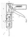
図1は、1つ以上の外科用ファスナを展開するための外科用器具2の一実施形態を示している。外科用器具は、ハンドル4と、ハンドル4から遠位に延びる細長シャフト6とを含む。細長シャフトの遠位端から展開されるファスナに加えて、細長シャフト6は、関節運動可能部分8を含むことができる。トリガー14は、図2に示されるように、関連するファスナ展開システム15を作動させ、ファスナを組織に展開するために、ハンドル上に設けられることができる。外科用器具はまた、器具を使用してファスナの展開が望まれるまで、ファスナ展開システムが器具によって担持されるファスナに予負荷などの力を加えることを防止するためにロックアウト150を含むことができる。 FIG. 1 depicts one embodiment of a surgical instrument 2 for deploying one or more surgical fasteners. The surgical instrument includes a handle 4 and an
図示され、以下により詳細に説明されるように、ロックアウト150は、ファスナ展開システム15に関連する細長シャフトの一部に取り付けられて、ファスナに予負荷が加えられるのを防止することができる。ファスナを展開するために外科用器具を使用することが望まれる場合、ロックアウト150をシャフトから取り外して、器具の作動前にファスナに予負荷を加えることを可能にすることができる。 As shown and described in more detail below, a
ファスナ展開システム15は、任意の数の異なる方法で具体化されることができる。しかしながら、図2に示される特定の実施形態では、ファスナ展開システムは、トリガー14、剛性リンケージ20、シャトル22、パワーアシスト装置24、および往復運動駆動シャフト26、ならびに図示されていない他の構成要素を含むことができる。トリガー14の作動は、剛性リンケージ20を遠位方向に変位させて、シャトル22を遠位方向に変位させ、エネルギーをパワーアシスト装置24に蓄積することができる。事前に選択された量の作動後、パワーアシスト装置24は、蓄積されたエネルギーを解放して、駆動シャフト26を遠位方向に加速し、細長シャフト6の遠位端からファスナを展開することができる。
特定のパワーアシスト装置24が示されているが、パワーアシスト装置24は、外科用器具の細長シャフト6からファスナを展開するのを助けることができる任意の適切な構造に対応することができる。特定の実施形態に応じて、パワーアシスト装置24は、トリガー14の作動に応答してファスナを展開するために必要な全ての電力を供給することができるか、またはファスナを展開するために必要な電力の一部のみを供給することができる。1つの特定の実施形態では、パワーアシスト装置24は、2013年3月14日に出願された、「POWER ASSIST DEVICE FOR A SURGICAL INSTRUMENT」と題された出願番号第13/804,043号に開示されたパワーアシスト装置に対応することができる。パワーアシスト装置を含む外科用器具が描かれているが、いくつかの実施形態では、外科用器具2は、パワーアシスト装置を含まなくてもよく、その場合、トリガー14の作動は、細長シャフト6の遠位端からファスナを展開するための適切なトランスミッションの使用を通じて直接的または間接的に駆動シャフト26を変位させることができる。 Although a particular
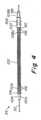
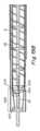
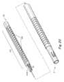
図3は、細長シャフト6の一実施形態と、細長シャフト内に配置された様々な構成要素との分解図を表している。図示の実施形態では、駆動シャフト26は、細長シャフト6内に配置されている。図2および図3に示されるように、細長シャフト6内に配置されると、駆動シャフト26は、細長シャフト6からハンドル4内に近位方向に延びる。外科用器具はまた、ファスナのスタック28、従動子34、および駆動シャフト26の内部チャネル内に配置されたアンチバックアップ要素を含む。従動子および/またはアンチバックアップ要素は、ファスナ展開システムまたはその一部に関連付けられることができる。ファスナのスタック28は、1つ以上のファスナ30を含むことができ、場合によっては、複数のファスナ30とすることができる。 FIG. 3 depicts an exploded view of one embodiment of the
上記の構成要素に加えて、外科用器具はまた、駆動シャフト26の内部チャネル内のファスナのスタック28、従動子34、およびアンチバックアップ要素36の位置合わせを維持するのを助けるためのファスナガイド32を含むことができる。任意の適切な構造を使用することができるが、図示の実施形態では、ファスナガイド32は、駆動シャフトのチャネルのほぼ中央に配置された遠位方向に延びるワイヤである。ファスナガイド32は、任意の適切な方法でチャネル内に保持されることができる。例えば、ファスナガイド32は、アンチバックアップ要素36の一部、ハンドル4の一部、または任意の他の適切な構造に取り付けられることができる。さらに、より高速なガイド32は、これらに限定されるものではないが、接着剤、機械的干渉、クランプ、はんだ付け、ろう付け、および溶接を含む任意の適切な方法を使用して取り付けられることができる。 In addition to the components described above, the surgical instrument also includes a
トリガーが作動すると、ファスナ展開システムが作動して、駆動シャフト26の遠位変位をもたらすことができる。以下により詳細に説明するように、駆動シャフト26の遠位変位は、ファスナ展開位置に配置された最遠位のファスナを展開する。駆動シャフト26はまた、ファスナのスタック28を変位させ、次に最遠位のファスナをファスナ展開位置に配置するように、従動子34を遠位方向に変位させる。従動子34およびアンチバックアップ要素36は、従動子34の遠位変位が、従動子34の近位移動を防止するために遠位方向に延びるアンチバックアップ要素をもたらすように関連付けられることができる。ファスナを展開し、次のファスナをファスナ展開位置に配置した後、駆動シャフト26を近位方向に動かして、次の作動のために外科用器具を準備するとともに、ファスナのスタック28、従動子34、およびアンチバックアップ要素36の近位移動を防止することができる。 Activation of the trigger can activate the fastener deployment system to effect distal displacement of
従動子34と駆動シャフト26との間の相互作用は、図4~図6に示されている。 The interaction between
図示の実施形態では、従動子34は、駆動部100、弾性構成要素102、およびプッシャ104を含む。駆動部100は、駆動シャフト26と相互作用して、従動子34を遠位方向に変位させるように適合されている。駆動部100は、駆動シャフト26の開口124と相互作用するタブ106を含む。タブ106は、可撓性であり、駆動部100から外側および遠位方向に延びることができる。さらに、タブ106は、駆動部100が駆動シャフト26を通って遠位方向に移動するときに、タブ106が開口124内に配置されることができるようなサイズ、形状、および配置とすることができる。駆動部100はまた、遠位部分108aならびに肩110を含むことができる。遠位部分108aおよび肩110は、弾性構成要素102の遠位端を遠位部分108a上に保持するようなサイズおよび形状とすることができる。遠位部分108aはまた、1つ以上の保持特徴116を含むことができる。図示のように、保持特徴116は、弾性構成要素102と干渉して弾性構成要素をその上に保持する遠位部分108aに配置された突起とすることができる。あるいは、弾性構成要素102は、これらに限定されるものではないが、機械的干渉、インターロック特徴、接着剤、溶接、はんだ付け、およびろう付けを含む任意の適切な方法を使用して、駆動部100上に保持されることができる。駆動部100はまた、近位部分108bに配置されたカップリング118を含むことができる。カップリング118は、従動子34をアンチバックアップ要素36に取り付けるように適合および配置されることができる。 In the illustrated embodiment,
一実施形態では、弾性構成要素102は、駆動部100とプッシャ104との間に延びるコイルばねである。上記のように、コイルばねが描かれているが、コイルばねの代わりに他のばねおよび適切な構成要素を使用することができる。弾性構成要素102として使用される特定の構成要素に関係なく、弾性構成要素102は、駆動部100およびプッシャ104の双方に関連するようなサイズ、形状、および配置とすることができる。さらに、ばねまたは他の適切な圧縮可能な構成要素の使用により、駆動部が遠位方向に移動されると、弾性構成要素102が圧縮されて、プッシャ104に力を加える。プッシャ104の移動前の駆動部100のより大きな変位は、弾性構成要素102のより大きな圧縮およびそれに対応してより大きな力をもたらすことができる。特定の実施形態に応じて、弾性構成要素102は、本開示がこのように限定されないため、線形力対変位関係、または非線形力対変位関係を示すことができる。 In one embodiment,
駆動部100と同様に、プッシャ104は、弾性構成要素102の遠位端を保持するようなサイズおよび形状の近位部分112bおよび肩114を含むことができる。プッシャ104はまた、駆動部100について上述したものと同様の弾性構成要素102を保持するための1つ以上の保持特徴116を含むことができる。プッシャ104はまた、ファスナスタックの最近位に配置されたファスナに力を加えるように適合および配置された遠位部分112aを含むことができる。いくつかの実施形態では、遠位部分112aは、ファスナのスタック内の少なくとも最近位のファスナに直接接触することができるが、遠位部分112aがファスナのスタックに間接的に力を加える実施形態も想定される。 Similar to drive
図5に示されるように、駆動シャフト26は、駆動シャフト26の遠位端に配置された1つ以上のファスナ駆動部120を含むことができる。いくつかの実施形態では、ファスナ駆動部120は、駆動シャフト26の遠位端から内側および遠位方向に延びる1つ以上の可撓性タブとすることができる。ファスナ駆動部120は、ファスナ展開位置に位置するファスナに力を加えて、細長シャフトの遠位端からファスナを展開するように適合されることができる。駆動シャフトはまた、細長シャフトの関節運動可能な部分を通る往復運動駆動シャフトの動きに対応するために、可撓性部分122を含むことができる。図示の実施形態では、可撓性部分122は、駆動シャフト26にスロットまたはカットのパターンを提供することによって形成される。上記のように、駆動シャフト26はまた、拡張位置において駆動部100のタブ106を収容するようなサイズおよび形状の開口124を含むことができる。開口124の1つ以上のセットは、駆動シャフト124の1つ以上の面に沿って軸方向に離隔されることができる。いくつかの実施形態では、開口124間の軸方向の間隔は、単一のファスナの長さに対応することができる。現在の実施形態では、2組の開口124が駆動シャフト26の反対側に沿って延在して、駆動部100のタブ106の双方を収容する。開口124は、駆動シャフト24の全体に沿って延在することができ、または図に示されるように、開口124は、全てのファスナが外科用器具から展開された後、従動子34の最初の近位位置および従動子34の最後の遠位位置に対応する駆動シャフト24の一部に沿って延在することができる。 As shown in FIG. 5, drive
駆動シャフト26および従動子34上の対応する特徴を説明したので、1つの可能な実施形態における作動中のこれらの2つの構成要素の相互作用を、図6を参照して説明する。作動前に、駆動部100のタブ106は、駆動シャフト26の対応する開口124のいずれか1つに拡張状態で配置されることができる。タブ106が対応する開口124内で拡張状態にある間、開口の近位端などの駆動シャフト124aの近位部分は、タブ106の近位側面106aと軸方向に位置合わせされることができる。その結果、駆動シャフト26が作動中に遠位方向に移動すると、近位駆動シャフト部分124aは、タブ106の近位側面106aに遠位方向の力を加え、駆動部100の遠位変位をもたらす。ファスナが展開された後、駆動シャフト26は、続いて近位方向に動かされる。駆動シャフト26の近位方向の移動中に、開口124の遠位縁などのシャフト124bの遠位部分は、タブの外面などの外側側面106b上に引かれることができる。以下により詳細に説明するように、駆動部100は、駆動シャフト26と駆動部100との相対的な移動中に後方に移動するのを防止することができる。さらに、上記のように、タブ106は可撓性である。したがって、遠位駆動シャフト部分124bがタブの外側側面106b上に引かれるとき、タブ106は、開口124の内側および外側に変位され、駆動部100および駆動シャフト26の相対的な動きを可能にすることができる。駆動シャフト26の近位変位は、タブ106が次に遠位方向に配置された開口124のセットと位置合わせし、タブ106が開口124内で拡張状態になるまで継続することができる。後続の作動サイクルは、駆動部100が駆動シャフトの次の対応する開口124のセットと係合するときに、遠位方向に漸進的に移動する駆動部100をもたらすことができる。上記を考慮して、従動子34の駆動部100および駆動シャフト26は、ファスナ展開システムの各作動サイクル中に従動子34を遠位方向に順次変位させるように構成された歩行ビームアセンブリの2つの別個の構成要素を形成すると説明することができる。 Having described the corresponding features on the
図7A~図7Bは、ファスナ展開システムの作動サイクル中のファスナのスタック28、従動子34、およびアンチバックアップ要素36の相互作用を示している。図に示されるように、プッシャ104は、ファスナスタック28の近位に配置されたファスナと接触することができる。弾性構成要素102はまた、プッシャ104の近位部分および駆動部100の遠位部分に関連付けられることができる。駆動部100は、カップリング130によって、アンチバックアップ要素36のラックアーム126に結合されることができる。駆動部100およびラックアーム126は、駆動部100の遠位方向の動きが、アンチバックアップ要素36の爪アーム128に対してラックアーム126の遠位方向の延長をもたらすことができるように結合されることができる。したがって、従動子34が細長シャフトを通って遠位方向に変位すると、アンチバックアップ要素36は、それに応じて伸長する。その結果、従動子34の近位方向の動きは、作動サイクル全体を通して、アンチバックアップ要素36によって防止されることができる。図に示されているように、カップリング130は、ピン接続に対応している。しかしながら、これらに限定されるものではないが、インターロック機械的特徴、止めねじ、ファスナ、接着剤、溶接、ろう付け、および締まり嵌めを含む任意の適切な接続が使用されることができる。 7A-7B illustrate the interaction of the
作動前に、図7Aに示されるように、従動子34の弾性構成要素102は、第1の長さに対応する拡張状態にあり、遠位方向に配置されたプッシャ104およびファスナのスタック28に第1の遠位方向の力を加えることができる。従動子34およびファスナのスタック28は、アンチバックアップ要素36によって近位方向に移動することが防止される。図示の実施形態では、アンチバックアップ要素36は、遠位方向に移動されることができるラックアーム126と、外科用器具の作動中に静止したままである爪アーム128とを含む。 Prior to actuation, the
図7Bを参照すると、ファスナ展開システムが作動されると、図示されていない駆動シャフトは、上述したように駆動部100を遠位方向に駆動する駆動部100のタブ106に力FDを加えることができる。近位方向に向けられた第1の拘束力FR1は、ファスナのスタック28に加えられることができる。最初に、第1の拘束力FR1は、力FDと等しくすることができる。したがって、作動の初期部分の間、ファスナのスタック28は、静止したままとすることができ、プッシャ104と駆動部100との間の弾性構成要素102の圧縮をもたらす。作動が続くと、弾性構成要素102がさらに圧縮されるにつれて、駆動部100に加えられる力が増加し続けることができる。この弾性構成要素102の継続的な圧縮は、ファスナのスタック28に増加する遠位方向の力を加える。作動中のある時点で、ばねは、弾性構成要素102に対応する第2の長さに圧縮されることができ、第2の遠位方向の力をプッシャ104および関連するファスナのスタック28に加える。この第2の遠位方向の力は、第1の拘束力FR1よりも大きくすることができ、弾性構成要素102の拡張、およびプッシャ104および関連するファスナのスタック28の遠位変位をもたらす。図7B~図7Cを参照のこと。Referring to FIG. 7B, when the fastener deployment system is actuated, a drive shaft (not shown) applies a force FD to
図に示されるように、弾性構成要素102は、ファスナのスタック28が遠位方向に変位されるにつれて、第2の長さから第1の長さまで拡張し続ける。弾性構成要素102が拡張された第1の長さに近付くと、近位方向の第2の拘束力FR2がファスナのスタック28に加えられて、ファスナのスタックのさらなる遠位方向の動きを防止することができる。第2の拘束力FR2は、弾性構成要素102によってファスナのスタック28に加えられる力、ならびにそれらが遠位方向に変位されるときにファスナのスタック28および従動子34に蓄積される可能な運動エネルギーの双方に対抗するために第1の拘束力よりも大きくすることができる。第2の拘束力はまた、細長シャフトからファスナを展開するための作動力よりも小さくすることができる。いくつかの実施形態では、スタックファスナ20の遠位方向に配置されたファスナがファスナ指定位置に配置されると、第2の拘束力FR2を加えることができる。ファスナのスタック28が遠位方向に変位され、ファスナ展開システムがリセットされた後、外科用器具を再び作動させて、従動子34および関連するファスナのスタック28のさらなる遠位方向変位をもたらすことができる。As shown, the
従動子34および関連するファスナのスタック28の変位に加えて、ファスナ展開システムの作動はまた、上記のように、アンチバックアップ要素36の延長をもたらすことができる。より具体的には、駆動部100およびラックアーム126が結合されているため、駆動部100の遠位変位は、爪アーム128に対するラックアーム126の対応する遠位変位をもたらすことができる。ラックアーム126の遠位方向の動きは、ファスナのスタック28が遠位方向に変位した後の駆動部100の後方への動きを防止するために、アンチバックアップ要素36を遠位方向に伸ばすことができる。ラックアーム126と爪アーム128との相互作用は、図8Aおよび図8Bにさらに詳細に示されている。歯134は、ラックアーム126の軸方向の長さに沿って離隔されることができる。対応する爪132は、爪アーム128の遠位部分に配置されることができる。爪132および対応する歯134は、駆動部の遠位移動に応答してラックアーム126の遠位移動を可能にするように適合および配置されることができる。爪132および対応する歯134はまた、ラックアーム126の近位方向の動きを防止するように適合および配置されることができる。一実施形態では、歯134間の距離は、1つのファスナの長さにほぼ等しくすることができる。しかしながら、歯134間の距離がファスナの長さの一部であるか、またはファスナの長さよりも大きい実施形態も想定される。上記に加えて、アンチバックアップ要素36についてラックおよび爪システムが描かれているが、従動子およびスタックファスナの後方への移動を防止することができる任意の適切な機構を使用することができる。 In addition to displacement of
上に示したように、従動子は34であり、ファスナのスタックに遠位方向の予負荷を加えて、ファスナのスタックをシャフトの遠位端に向かって駆動し、最遠位のファスナをファスナ展開位置に維持するように構成および配置される。いくつかの用途では、ファスナ展開に器具を使用することが望まれるまで、ファスナに予負荷が加えられるのを防止するロックアウトを採用することが望ましい場合がある。 As shown above, the follower is 34 and applies a distal preload to the stack of fasteners to drive the stack of fasteners toward the distal end of the shaft and to unfasten the distal-most fastener. configured and arranged to maintain in a deployed position. In some applications, it may be desirable to employ a lockout that prevents the fastener from being preloaded until it is desired to use the instrument for fastener deployment.
図9A~図10に示される一実施形態では、ロックアウト150は、細長シャフトに取り付けられ且つそれから取り外されることができるクリップとして構成されることができる。図示されるように、クリップ150は、シャフト6に取り付け可能な2対の対向する第1のクリップフィンガ152aおよび第2のクリップフィンガ152bと、クリップをシャフトから取り外すために把持および引っ張られるように構成された外向きに延びるグリップハンドル154とを含むことができる。グリップハンドルを把持してロックアウトをシャフトから引き抜くユーザの能力を高めるために、1つ以上の特徴が設けられることができる。一実施形態では、1つ以上の隆起したリブ156は、グリップハンドルの外周の少なくとも一部の周りに延びることができる。当業者にとって明らかなはずであるように、他の適切なグリップ特徴を利用することができることを理解されたい。 In one embodiment shown in FIGS. 9A-10,
クリップフィンガ152a、152bは、シャフト6の外面に一致するように構成されることができる。例えば、一実施形態では、クリップフィンガ152a、152bは、シャフトの形状に対応する反対の湾曲した形状を有することができる。クリップフィンガは、クリップを取り付けたり取り外したり、それらの間の細長シャフトを把持したりするためにフィンガを開閉することを可能にする十分な弾力性または可撓性を有することができる。2対の対向するクリップフィンガを有するように示されているが、ロックアウトは、1対または2対より多い対を含む任意の数のクリップフィンガを含むことができることを理解されたい。さらに、当業者にとって明らかなはずであるように、細長シャフトにロックアウトを取り付けたり取り外したりするための他の適切な構成を採用することができる。 The
グリップフィンガは、細長シャフトに対するロックアウトの取り付けおよび取り外しを容易にするために、任意の適切な構成で配置されることができる。図9A~図9Bに示されるように、クリップフィンガは、ロックアウトの第1の面に設けられた第1のフィンガ152aが第1の長さL1だけ離隔され、第2のフィンガ152bが第1の長さL1とは異なる第2の長さL2だけ離隔されてロックアウトの第2の反対面に設けられて配置されることができる。一実施形態では、第1のフィンガ152aの間の第1の長さL1は、第2のフィンガ152bの間の第2の長さL2よりも短い。図示のように、第1のフィンガ152aは、第2のフィンガ152bの内側に配置されることができ、第2のフィンガ152bは、ロックアウトの両端に配置されることができる。The grip fingers may be arranged in any suitable configuration to facilitate attachment and removal of the lockout from the elongated shaft. As shown in FIGS. 9A-9B, the clip fingers are such that a
ロックアウト150はまた、クリップが細長シャフトに取り付けられたときにファスナ展開システムと協働するように構成されたピン158を含むことができる。図10に示されるように、ピン158は、ファスナに向かうファスナ展開システムの遠位方向の動きを防止するために、グリップハンドル154から、細長シャフト6の対応する孔160を通って、シャフトの内部チャネル162内に内側に延びるように配置されることができる。図10に示される一実施形態では、ピン158は、従動子がファスナに係合して予負荷または他の力を加えないように、ファスナのスタック28から離隔関係で従動子34を維持するように配置されることができる。より具体的には、クリップは、ピン158がシャフトを通って延在し、ファスナのスタック28と従動子34との間に配置され、ピン158が遠位方向に付勢されたプッシャ104の肩114に係合するように配置される。細長シャフトからクリップ150を取り外し、内部チャネルからピン158を取り外すことは、プッシャ104が最近位のファスナ30と係合するように移動し、ファスナ展開システムの作動時にその後のファスナの位置決めおよび展開のためにファスナのスタック28に対して予負荷力を加えることを可能にする。
例示的な一実施形態では、ロックアウトは、約1.25インチの全長Lとすることができ、第1のフィンガ152aは、約0.65インチの長さL1だけ離隔され、第2のフィンガは、約1.09インチの長さL2だけ離隔される。クリップフィンガ152は、約0.22インチの内径を有する曲率を有して構成されることができ、フィンガの自由端は、約0.15インチの幅W1だけ離隔されている。グリップハンドル154は、クリップフィンガの中心から約1.18インチの長さL3を有することができる。ピン158は、約0.03インチの直径を有することができ、グリップハンドルの表面から約0.07インチの長さL4だけ延びることができる。ロックアウト寸法は例示的なものであり、ロックアウトは、当業者にとって明らかなはずである任意の適切な形状および/またはサイズを使用することができることを理解されたい。In one exemplary embodiment, the lockout may have an overall length L of approximately 1.25 inches, with the
上に示したように、鋭利な物体を取り扱うための特定のプロトコルにしたがってロックアウトの廃棄を必要とする可能性があるピン158または同様の構成要素の存在のため、ロックアウトは、鋭利な物体と見なされることができる。例えば、ロックアウトは、後で廃棄するために鋭利な容器に入れる必要がある場合がある。ロックアウトを取り扱う個人による潜在的な接触の発生率を低減するために、ピンまたは他の潜在的な鋭利な構成要素を遮蔽するためのカバーまたは他の適切な配置を提供することが望ましい場合がある。 As indicated above, the lockout cannot be used with sharp objects due to the presence of
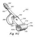
図11A~図11Cに示される1つの例示的な実施形態では、ロックアウト150は、ロックアウトが外科用器具の細長シャフト6から取り外されるときに、ピン158を覆って個人による接触から遮蔽するように構成されたシュラウド170を含むことができる。シュラウドは、シャフトに対するロックアウトの取り付けおよび取り外しを容易に可能にするように開閉するように構成されることができる。図に示されるように閉じられると、シュラウド170は、ロックアウトがシャフトに取り付けられたときにクリップフィンガ152a、152bならびに細長シャフト6を包み込んで覆うように設計された管状構成を有することができる。 In one exemplary embodiment shown in FIGS. 11A-11C, the
シュラウド170は、ベース172と、ロックアウトがシャフトに対して取り付けられるおよび取り外されるときにロックアウトを取り付けおよび取り外しするためにクリップフィンガに対して開くことができ且つクリップフィンガおよびピンを取り囲むように閉じることができる、ベースから延びる1対のシュラウドセグメント174a、174bとを含むことができる。各シュラウドセグメント174a、174bは、シュラウドが閉じた構成にあるときに、約180°の管状構造を形成するように構成された弧状の形状を有することができる。 A
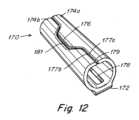
図12に示される一実施形態では、シュラウドセグメント174aの1つの少なくとも一部は、180°を超えて延在して、ロックアウトが細長シャフトから取り外されたときにシュラウドセグメントがピンに向かって内側に折り畳まれた場合にピンを覆うように構成される舌などの延長部176を形成することができる。対向するシュラウドセグメント174bは、シュラウドセグメントが閉じられたときに延長部176を受け入れるように構成された凹部181を含むことができる。図示のように、シュラウドセグメントの自由端177a、177bは、閉じた位置で互いに近接して配置されて、それらの間に比較的狭いギャップ179を形成することができる。 In one embodiment shown in FIG. 12, at least a portion of one of the
シュラウド170は、ロックアウト150に結合されることができる別個の構成要素として製造されることができる。図11A~図11Cに示される一実施形態では、シュラウド170は、ベース172がロックアウトハンドル154の端部に隣接して配置され、シュラウドセグメント174a、174bがベースからクリップフィンガ152a、152bの周りに延在するように構成されることができる。図12に示されるように、ベースは、ロックアウト上にシュラウドを配置するためにそれを通してグリップハンドル154をスライド可能に受け入れるように構成されたスロット178または他の適切な開口を含むことができる。
ロックアウトは、シュラウドをその所望の位置に維持するために1つ以上のロック特徴を含むことができる。図11A~図11Cに示される一実施形態では、1対のロック180は、シュラウドがロックアウト上に配置されたときにベース172に係合するために、クリップフィンガに近接してグリップハンドル154の反対側に設けられることができる。各ロック180は、ロックとクリップフィンガとの間の位置へのシュラウドの配置を容易にし、その後、クリップフィンガから離れるシュラウドの動きを制限するカム状構成を含むことができる。一実施形態では、各ロック180は、シュラウドをロック上でクリップフィンガに向かう方向にわたって所定の位置にスライドすることを容易にする傾斜路状面182と、ベースに当接してクリップフィンガから離れる方向へのシュラウドの動きを制限するストップとして機能するように構成された傾斜路状面の端部にある当接部184とを含むことができる。当業者にとって明らかなはずであるように、任意の適切なロック構成を使用できることを理解されたい。 The lockout may include one or more locking features to maintain the shroud in its desired position. In one embodiment shown in FIGS. 11A-11C, a pair of
シュラウド170は、シュラウドセグメントの開閉、ならびにロックアウト上のシュラウドの配置を容易にする可撓性構成を有するように形成されることができる。このように、シュラウドは、クリップフィンガによって行われるように、器具の細長シャフトを把持および保持する必要がない。しかしながら、必要に応じて、当業者にとって明らかなはずであるように、シュラウドセグメントは、シャフト上のロックアウトを保持するのを助けるように構成されることができる。
一実施形態では、シュラウドは、可撓性特性を提供するのに役立つ材料から形成されることができる。例えば、限定されるものではないが、シュラウドは、ポリウレタンまたはポリエチレン材料から成形されることができるが、当業者にとって明らかなはずであるように、他の適切な材料を使用することができる。 In one embodiment, the shroud can be formed from a material that helps provide flexible properties. For example, and without limitation, the shroud can be molded from polyurethane or polyethylene materials, although other suitable materials can be used, as should be apparent to those skilled in the art.
状況によっては、手術室などの特定の環境内で構成要素が緩むのを避けることが望ましい場合がある。例えば、緩んだ構成要素は、潜在的に置き忘れられる可能性があり、構成要素を見つけて消息を知るのに時間がかかる可能性がある。したがって、外科用器具のシャフトから取り外されたときに潜在的に置き忘れられる可能性のあるロックアウトを有することを回避することが望ましい場合がある。 In some situations, it may be desirable to avoid components becoming loose within certain environments, such as an operating room. For example, a loose component can potentially be misplaced, and it can take time to locate and learn the whereabouts of the component. Therefore, it may be desirable to avoid having a lockout that can potentially be misplaced when removed from the shaft of a surgical instrument.
一実施形態では、ロックアウトは、外科用器具の包装トレイまたはブリスターパックに結合されることができる。ロックアウトを器具から取り外して器具を使用できるようにするとき、ロックアウトは、トレイに取り付けられたままであるため、外科手術中に誤って置き忘れることはない。 In one embodiment, the lockout can be coupled to a surgical instrument packaging tray or blister pack. When the lockout is removed from the instrument to enable use of the instrument, the lockout remains attached to the tray so that it cannot be accidentally misplaced during a surgical procedure.
図13に示される一実施形態では、ロックアウト150は、一端がトレイに取り付けられ、その反対側の端がロックアウトに取り付けられているテザー188を使用して、トレイ186に結合されることができる。図11A~図11Cに示されるように、テザー188は、グロメット192、または他の適切な構成要素と一体に結合されたストラップの自由端190を備えたループとして形成されたストラップを含むことができ、これらは、リベットなどのファスナ193によってトレイに取り付けられることができる。ストラップのループ端は、ロックアウトのグリップハンドル152に結合されることができる。一実施形態では、ストラップ188は、グリップハンドルのスロットまたは他の適切な開口などの孔194を通してループされることができる。 In one embodiment shown in FIG. 13,
テザー188は、器具の取り外しおよび操作を可能にするのに十分な長さで構成されることができるとともに、器具から取り外されたときにロックアウトがトレイから過度にぶら下がらないように、トレイに比較的近接して分離されたロックアウトを維持する。一実施形態では、テザーは、約1.75インチの長さを有することができるが、当業者にとって明らかなはずであるように、任意の適切な長さのテザーを使用することができる。 The
ロックアウトは、鋭利な物体と見なされることができるため、処置にしたがって廃棄しやすくするために、ロックアウトをトレイから取り外すことが望ましい場合がある。必要に応じて、テザーを切断するか、トレイまたはロックアウトのいずれかから取り外して、トレイからロックアウトを取り外すことができる。いくつかの用途では、ロックアウトは、テザーからの分離を容易にするように構成されることができる。 Because the lockout can be considered a sharp object, it may be desirable to remove the lockout from the tray to facilitate disposal following the procedure. If desired, the lockout can be removed from the tray by cutting the tether or removing it from either the tray or the lockout. In some applications, the lockout can be configured to facilitate separation from the tether.
図11A~図11Bに示される一実施形態では、ロックアウト150は、スロット196(図11Aの想像線に示される)または、例えば、ロックアウトからテザーを滑らせることによってテザーの取り外しを可能にするように構成された他の適切な通路を含むことができる。示されるように、スロット196は、テザー188をロックアウトに取り付けるために使用されるグリップハンドルの孔194から、グリップハンドルの外周を通って延びるように構成されることができる。スロット196は、孔194を横切って配向されることができ、テザーの縁がスロットに且つスロットを通って滑ることができるようにテザーおよびロックアウトが互いに対して操作されるときにテザーがスロットを通って滑ることを可能にするために、テザーの幅ではなく厚さを収容するのに十分な幅を有することができる。一実施形態では、スロット196は、孔194に対して垂直に向けられることができる。当業者にとって明らかなはずであるように、ロックアウトをテザーに取り外し可能に結合するために、他の適切な構成を使用することができることを理解されたい。 In one embodiment shown in FIGS. 11A-11B, the
ロックアウトは、外科用器具の組み立て中に細長シャフトに取り付けられて、ファスナのスタックが予負荷を受ける時間を最小限に抑えることができる。しかしながら、当業者にとって明らかなはずであるように、ロックアウトは、任意の適切な時間に外科用器具に取り付けられることができることを理解されたい。 The lockout can be attached to the elongated shaft during assembly of the surgical instrument to minimize the time the fastener stack is preloaded. However, it should be understood that the lockout can be attached to the surgical instrument at any suitable time, as should be apparent to those skilled in the art.
一実施形態では、ロックアウトは、従動子34のプッシャ104を、ファスナのスタックから離れる近位方向に且つばね102の付勢力に逆らって最初に変位させることによって取り付けられることができる。プッシャ104は、シャフト6を通る孔160の近位にプッシャの肩114を配置するのに十分な距離だけ変位されることができる。その後、ロックアウト150は、ピン158が孔160を通ってファスナ30とプッシャ肩114との間の内部チャネル162内に延びるようにクリップフィンガをシャフト6に押し付けることによって器具に取り付けられることができる。ロックアウトが取り付けられると、肩114がピン158に係合するまでばね102がプッシャを遠位方向に駆動して、プッシャがファスナのスタック28に向かってさらに前進するのを防止するように、従動子34が解放されることができる。ピン158によって係合されるとき、プッシャ104は、従動子がファスナに予負荷を加えないように、ファスナのスタックから適切な距離だけ離隔される。 In one embodiment, the lockout may be installed by first displacing the
一実施形態では、テザーは、プッシャ104に取り付けられ、ロックアウトの取り付けを容易にするために従動子をファスナから引き離すためにアクセス可能であり且つ使用することができる位置まで細長シャフト6に沿って近位方向に延びることができる。テザーは、プッシャを近位方向に把持および引っ張るために利用可能なテザーの十分な長さを有してハンドル4の近位端を通って延在し且つ出ることができる。ロックアウトがシャフトに取り付けられた後、テザーを取り外して器具から取り外すことができる。 In one embodiment, the tether is attached to the
一実施形態では、テザー164は、図14に示されるように、プッシャから延在し且つハンドル4から出るテザーの2つのセグメントを備えたプッシャを通してループされることができる。ロックアウトクリップが取り付けられた後、器具からテザーを取り外すために、テザーの一方のセグメント164aを近位方向に引っ張って、テザーの他のセグメント164bをハンドル、シャフト、プッシャを通して遠位方向に引き、最終的にはシャフトおよびハンドルを通して近位方向に引き戻すことができる。 In one embodiment,
ロックアウト150は、任意の適切な配置を採用することができるが、ワンピース構成要素として形成されることができる。ピン158は、クリップと一体化される別個の構成要素とすることができる。例えば、一実施形態では、ピン158は、グリップ154にインサート成形されることができる。そのような配置は、プラスチック材料から形成されることができるクリップと比較して、金属などの比較的強い材料から製造されたピンの使用を可能にする。
一実施形態では、クリップフィンガ152およびグリップ本体154は、Trinseoから入手可能なCALIBRE 2061-15 FC850122などのポリカーボネート樹脂から一体的に形成されることができる。ピン158は、304ステンレス鋼から形成されることができ、ASTM F899にしたがって完全に硬く、ASTM A967にしたがって不動態化され、クリップ材料によってインサート成形されて、5ポンドの最小引き抜き力を有するそれらの間の接続を提供する。しかしながら、ロックアウトは、任意の適切な技術を使用して、および/または当業者にとって明らかなはずであるように任意の適切な引き抜き力を提供するために、任意の適切な材料から製造されることができることが理解されたい。 In one embodiment, clip
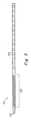
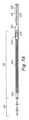
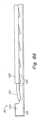
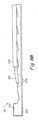
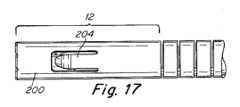
図15~図18は、細長シャフト6の構成要素である内側管状部材200を示している。内側管状部材200は、細長シャフト6の遠位端を形成する剛性直線部分12を含む。内側管状部材はまた、剛性直線部分12内に配置された1つ以上の第1の拘束部202および1つ以上の第2の拘束部204を含むことができる。図15に示されるように、2つの第2の拘束部204は、第1の拘束部202に対して遠位方向に配置されている。第1の拘束部は、作動中にファスナのスタックに第1の拘束力を提供するように適合および配置されることができる。それに対応して、第2の拘束部204は、作動中にスタックファスナに第2の拘束力を提供するように適合および配置されることができる。前述のように、第1の拘束力は、第2の拘束力よりも小さくすることができる。本開示は、拘束力がファスナのスタックに適用される方法に限定されないため、異なる拘束力は、任意の数の方法で提供されることができる。いくつかの実施形態では、拘束部は、細長シャフト、または細長シャフトの構成要素と一体的に形成されることができる。あるいは、拘束部は、別個に形成され、これらに限定されるものではないが、溶接、はんだ付け、ろう付け、接着剤、締まり嵌め、およびファスナを含む任意の適切な方法で細長シャフトとともに組み立てられることができる。 15-18 illustrate an inner
異なる第1および第2の拘束力は、任意の適切な方法で提供されることができる。例えば、一実施形態では、第1および第2の拘束部の異なる順応性を使用して、異なる第1および第2の拘束力を提供することができる。より具体的には、第2の拘束部は、第1の拘束部よりも低い順応性とすることができる。別の実施形態では、異なる数の第1および第2の拘束部を使用して、異なる第1および第2の拘束力を提供することができる。そのような実施形態では、第1の拘束部の数と比較して、より多くの第2の拘束部を使用することができる。異なる拘束力を提供する特定の方法が上で述べられているが、拘束力を提供する他の方法もまた想定される。 Different first and second restraining forces can be provided in any suitable manner. For example, in one embodiment, different compliabilities of the first and second restraints may be used to provide different first and second restraint forces. More specifically, the second restraint can be less compliant than the first restraint. In other embodiments, different numbers of first and second restraints can be used to provide different first and second restraint forces. In such embodiments, a greater number of second restraints may be used compared to the number of first restraints. Although specific methods of providing different binding forces are described above, other methods of providing binding forces are also envisioned.
1つの可能な実施形態において、および図15~図18に示されるように、第1および第2の拘束部202および204は、細長シャフトの内側管状部材200に対して内側および遠位方向に延びるタブに対応することができる。所望の第1および第2の拘束力を提供するために、単一のより順応性のある第1の拘束力202および2つのより順応性の低い第2の拘束力204が、細長シャフトの内側管状部材200の剛性直線部分12に組み込まれる。第2の拘束部204に対応するタブは、第1の拘束部202に対応するタブと比較して、減少した長さ、および/または増加した幅を有することができる。理論に拘束されることを望まないが、これは、第2の拘束部204が第1の拘束部202よりも順応性が低くなることをもたらす。結果として、第1の拘束部202についての単一のより順応性のあるタブと比較して、第2の拘束部204についての2つのより順応性の低いタブの使用により、図示された実施形態は、第1の拘束力よりも大きい第2の拘束力を提供するように適合される。第1および第2の拘束部の特定の配置が図に示されて上述されているが、第1および第2の拘束力を提供するための他の実施形態も可能であることを理解されたい。 In one possible embodiment, and as shown in FIGS. 15-18, the first and
第1の拘束部202、第2の拘束部204、ファスナ30、およびファスナ展開システムの駆動シャフト26の間の相互作用が、ファスナ展開システムの作動中の細長シャフト6の遠位部分の一連の断面を示す図19A~図19Cに示されている。作動前に、遠位方向に配置されたファスナ30は、ファスナ展開位置206に配置される。ファスナ展開位置206は、第1の拘束部202および第2の拘束部204の相対的な位置によって画定されることができる。第1の拘束部202および第2の拘束部204は、作動前にそれらの間にファスナ30のヘッド30aを保持することによってファスナ展開位置を画定することができる。拘束部202および204を使用してファスナ30をファスナ展開位置206に保持することは、ファスナが細長シャフト6から不注意に移動するのを防止するだけでなく、その後の展開のためにファスナの一貫した位置を提供するのに有益である。ファスナ展開システムが作動すると、駆動シャフト26が遠位方向に変位し、ファスナ展開位置206に配置されたファスナ30に力を加えるファスナ駆動部120をもたらす。加えられた作動力は、図19Bに示されるように、ファスナの遠位変位および展開をもたらす第2の拘束部204によって提供される第2の拘束力よりも大きい。上記のように、ファスナのスタックは、ファスナのスタックを遠位方向に変位させ、次の作動サイクルのために次のファスナをファスナ展開位置206に配置するために加えられる別個の力を有することができる。駆動シャフト26が近位方向に引き抜かれ、次の作動サイクルのためにファスナ展開システムをリセットすると、ファスナ駆動部120は、ファスナ展開位置206に位置するファスナ30のヘッド30aの周りを通り過ぎて変形する。図19Cを参照のこと。図に示されるように、第1および第2の拘束部202および204に対応するタブは、拘束部202および204から遠位方向に配置されたファスナ30の近位方向の動きに抵抗するように配置および適合されることができる。その結果、ファスナ展開位置206に配置されたファスナ30の近位方向の動きは、駆動シャフトが近位方向に動かされるときに、第1の拘束部202によって防止されることができる。駆動シャフト26が近位方向に完全に動かされると、外科用器具は、次のファスナを展開する準備ができている。 The interaction between the
上述した実施形態は、近位および遠位方向の駆動シャフトの往復運動によって駆動される従動子を対象としてきたが、他の実施形態が可能である。例えば、一実施形態では、従動子は、駆動シャフトの回転が、従動子および駆動シャフト内に配置された関連するファスナの遠位変位をもたらすことができるように、回転する駆動シャフトに関連付けられることができる。別の例示的な実施形態では、従動子は、ファスナ展開システムの作動が従動子の遠位移動をもたらすように、ファスナ展開システムの別の構成要素と関連付けられることができる。例えば、従動子は、トリガー14、剛性リンケージ20、またはシャトル22に関連付けられることができる。さらに、従動子は、直接的または間接的に、上記構成要素のいずれかに関連付けられることができる。 Although the embodiments described above have been directed to followers driven by reciprocating motion of the drive shaft in the proximal and distal directions, other embodiments are possible. For example, in one embodiment, the follower is associated with a rotating drive shaft such that rotation of the drive shaft can result in distal displacement of the follower and associated fasteners disposed within the drive shaft. Can be done. In another exemplary embodiment, the follower can be associated with another component of the fastener deployment system such that actuation of the fastener deployment system results in distal movement of the follower. For example, the follower may be associated with
前述のように、ファスナのスタックを変位させて次のファスナをファスナ展開位置に配置することに加えて、いくつかの実施形態では、細長シャフト内でファスナの特定の向きを維持することが望ましい場合がある。図20は、細長シャフト6と、細長シャフト6の内部に配置されることができる駆動シャフト26との概略分解図を示している。細長シャフト6の外側に形成されたスロットの描写されたパターンは、関節運動可能部分8に対応する細長シャフト6の部分に可撓性を与える。図示された実施形態では、駆動シャフトは、その中に配置された1つ以上のファスナ30を収容するための内部チャネルを含む。駆動シャフト26はまた、ガイド面136を含むことができる。ガイド面136は、任意の適切な形状とすることができ、図に示されるように、駆動シャフト26の軸方向に沿って延びる平坦部に対応することができる。ガイド面136は、ファスナ30上の対応する面と相互作用して、ファスナが駆動シャフト26内に配置されている間、および駆動シャフトが作動中に遠位位置と近位位置との間で往復運動するときに、ファスナの配向を維持することができる。ガイド面136に加えて、駆動シャフト26はまた、ファスナ30上の対応する面と相互作用して、ファスナ展開位置に配置されたときにファスナ30の配向を維持するファスナ駆動部120aを含むことができる。 In addition to displacing a stack of fasteners to place the next fastener in a fastener deployment position, as described above, in some embodiments it may be desirable to maintain a particular orientation of the fastener within the elongated shaft. There is. FIG. 20 shows a schematic exploded view of an
図示された実施形態では、ガイド面136に対応する平坦部が駆動シャフト26の内部チャネルの内面に存在する。さらに、ガイド面136は、必要に応じて、駆動シャフト26の外面にも存在することができる。ガイド面136について特定の形状が描かれているが、駆動シャフト26には、そこに配置されたファスナ30の向きを維持するために、任意の適切な形状または特徴の組み合わせが存在することができる。例えば、ガイド面136は、突起、溝、または他の任意の適切な形状に対応することができる。さらに、ガイド面136は、駆動シャフト26の任意の適切な部分に沿って延びることができる。例えば、本開示はこのように限定されていないため、ガイド面136は、駆動シャフトの遠位部分、駆動シャフトの可撓性部分122、駆動シャフト内に配置されたファスナのスタックに対応する駆動シャフトの部分、または駆動シャフトの全長に沿って延びることができる。 In the illustrated embodiment, a flat portion corresponding to the
図21~図23は、駆動シャフト26とともに使用するためのファスナ30の1つの可能な実施形態を示している。ファスナ30の図示された実施形態は、以下を含む:ヘッド30a、ヘッド30aから延びるシャフト30b、およびシャフト30bの遠位端に配置されたとげのある端部30c。駆動シャフトのガイド面136に対応する面138は、ヘッド30a上に配置されることができる。面138は、ファスナ30が駆動シャフト26の内面と滑らかにインターフェースするように、ガイド面136が駆動シャフトを補完するようなサイズおよび形状とすることができる。図示された実施形態では、面138は、ヘッド30aの断面が駆動シャフトの内部チャネルの断面の対応する平坦部および円形部を補完するようなサイズおよび形状の平坦部および円形部を含むように平坦部に対応する。ガイド面136に対応する面138は、ファスナのヘッド30a上に配置されるように描かれているが、面138は、ファスナ30の任意の適切な部分上に配置されることができる。例えば、シャフト30bまたはとげのある端部30cの一部は、ファスナ30の配向を維持するために駆動シャフトのガイド面136と相互作用するような形状、サイズ、および配置である対応する面または特徴を含むことができる。 21-23 illustrate one possible embodiment of a
ガイド面136に対応するファスナ30上に存在する面138に加えて、ファスナ30はまた、ヘッド30aの近位表面からシャフト30bおよびとげのある端部30cを通って遠位方向に延びる貫通孔140を含むことができる。貫通孔140は、上述したようにファスナガイドを収容して、細長シャフト内でファスナ30の位置合わせを維持するようなサイズおよび形状とすることができる。貫通孔140が配置される場所に関して本開示が限定されないため、貫通孔140は、中央に配置され、半径方向にオフセットされ、または他の任意の適切な場所に配置されることができる。細長シャフト内でファスナ30の位置合わせを維持するのを助けるために貫通孔140を含むことが望ましい場合があるが、特定の実施形態では、図に示されるようにファスナに尖った先端142を設けることも望ましい場合がある。しかしながら、鈍い先端および関連する穿刺針を使用する実施形態もまた想定される。貫通孔140を収容するために、尖った先端142は、貫通孔140に対して半径方向にオフセットされることができる。 In addition to the
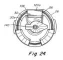
図24は、駆動シャフト26の内部チャネル140内に配置された遠位方向に配置されたファスナ30を示している。図によって示されるように、駆動シャフト26のガイド面136およびファスナ駆動部120aは、ファスナ30の対応する面138と位置合わせされている。内部チャネル断面の平坦部とファスナヘッド(すなわち、ガイド面136および対応する面138)、ならびに内部チャネル断面の円形部とファスナヘッドとの相互作用のために、ファスナ30は、駆動シャフト26の長さ全体にわたって事前に選択された向きに維持されることができる。 FIG. 24 shows distally positioned
図25は、細長シャフト6内に配置された図24のファスナ30および駆動シャフト26を示している。図19Bによって最もよく示されるように、いくつかの実施形態では、ファスナ駆動部120は、駆動シャフト26がファスナを展開するために遠位方向に変位されるとき、第1および第2の拘束部202および204に対して遠位方向に延びることができる。したがって、ファスナ駆動部120と、第1および第2の拘束部202および204は、駆動シャフトの遠位変位中に互いに干渉しないように配置することが望ましい場合がある。図示された実施形態では、ファスナ駆動部120は、ファスナ駆動部122が駆動シャフトの遠位変位中に第1および第2の拘束部202および204に干渉しないように、駆動シャフト26の遠位端に三角形パターンで配置され、第1および第2の拘束部202および204は、細長シャフト6の内面の周りに別の対応する三角形パターンで配置される。ファスナ駆動部および拘束部の特定の数および配置が図に示されて本明細書に記載されているが、本開示は、このように限定されないことを理解されたい。代わりに、適切な数および配置のファスナ駆動部および拘束部が使用されることができる。さらに、他の適切なタイプのファスナ駆動部および拘束部も使用されることができる。 25 shows the
上に示したように、細長シャフト6は、関節運動可能部分8を含むことができる。関節運動可能部分は、関節制御10を使用して、非関節(すなわち、直線)位置などの第1の位置と、完全に関節位置などの第2の位置との間で関節運動することができる。いくつかの実施形態では、関節運動可能部分8は、第1の位置と第2の位置との間でのみ関節運動することができる。他の実施形態では、本開示がこのように限定されないため、関節運動可能部分8は、1つ以上の事前選択された関節位置、または任意の(すなわち、事前選択されていない)関節位置に関節運動されることができる。さらに、実施形態に応じて、関節運動可能部分8は、一方向にのみ関節運動することができ、またはそれは2方向に関節運動することができる。例えば、関節運動可能部分8は、約0°と90°、0°と45°、-90°と90°、-180°と180°、または任意の他の適切な範囲の角度の間で関節運動することができる。さらに、いくつかの実施形態では、関節運動可能部分8は、2つの異なる軸の周りで関節運動することができる(例えば、水平方向および垂直方向の関節運動)。 As shown above,
いくつかの実施形態では、遠位先端の位置決めを容易にするために、細長シャフト6を回転させることが望ましい場合がある。そのような一実施形態が、図1および図18に示されている。細長シャフト6の回転は、任意の適切な方法で提供されることができる。例えば、細長シャフト6は、ハンドル4の少なくとも一部に対して回転可能であるように単に適合されることができる。あるいは、細長シャフト6を含むハンドル4の一部は、グリップを含む部分など、ハンドル4の別の部分に対して回転可能とすることができる。そのような実施形態の1つが図1に示されている。図示された実施形態では、外科用器具2は、細長シャフト6を含む第1のハンドル部分16および第2のハンドル部分18を含む。第1および第2のハンドル部分16および18は、互いに対して回転可能であるように任意の適切な方法で構成および配置されることができる。回転可能な細長シャフト6またはハンドル4を含む外科用器具が図に示されているが、本開示がこのように限定されていないため、単一のハンドルおよび/またはハンドルに対して静止している細長シャフト6を含む外科用器具もまた可能であることを理解されたい。 In some embodiments, it may be desirable to rotate
特定の用途では、関節運動可能部分8から遠位方向に配置された剛性直線部分12を含むことが有利な場合がある。例えば、理論に拘束されることを望まないが、曲線を一周するときに駆動シャフトがファスナに力を加えるとき、駆動シャフトによってファスナの近位部分に加えられる力は、ファスナの展開方向と位置合わせされない場合がある。これは、細長シャフト6の側面に向けられる加えられた力の一部をもたらすことができる。対照的に、駆動シャフトが直線部分に沿ってファスナに力を加える場合、加えられる力は、ファスナの展開方向に位置合わせされる。したがって、関節運動可能部分8から所与の長さにわたって遠位方向に延びる剛性直線部分12を含むことは、加えられた作動力が展開方向と位置合わせされることができるため、駆動シャフトが低減された作動力を加えてファスナを展開することを可能にすることができる。さらに、展開方向に位置合わせされた作動力を加えることはまた、外科用器具が異なる関節角度間で変化するため、ファスナ展開の一貫性も改善することができる。上記の利点に加えて、剛性直線部分12はまた、外科用器具からのファスナの位置決めおよび展開を支援するために他の構成要素または特徴を組み込むことができる。遠位剛性直線部分12を含む外科用器具2が本明細書に記載され、図に示されているが、外科用器具が遠位剛性直線部分を含まないように関節運動可能部分8が細長シャフト6の遠位端まで完全に延びる実施形態も想定されることを理解されたい。 In certain applications, it may be advantageous to include a rigid
本教示は、様々な実施形態および実施例と併せて説明されてきたが、本教示がそのような実施形態または実施例に限定されることを意図するものではない。それどころか、本教示は、当業者によって理解されるように、様々な代替例、変更例、および均等物を包含する。したがって、前述の説明および図面は、例としてのみのものである。 Although the present teachings have been described in conjunction with various embodiments and examples, it is not intended that the present teachings be limited to such embodiments or examples. On the contrary, the present teachings encompass various alternatives, modifications, and equivalents, as would be understood by those skilled in the art. Accordingly, the foregoing description and drawings are given by way of example only.
Claims (42)
Translated fromJapanese前記ハンドルから遠位方向に延びる細長シャフトであって、該細長シャフトが前記ハンドルとは反対側の遠位端を含む細長シャフトと、
前記細長シャフト内に配置された少なくとも1つのファスナと、
その作動に応答して前記細長シャフトから前記少なくとも1つのファスナを展開するように構成されたファスナ展開システムであって、その作動前に前記少なくとも1つのファスナに前記遠位方向に第1の負荷を加えて前記少なくとも1つのファスナを前記細長シャフトの遠位端に近接したファスナ展開位置に維持し、前記細長シャフトの遠位端から遠ざかる近位方向への前記少なくとも1つのファスナの移動を防止するように構成されたファスナ展開システムと、
前記細長シャフトに取り外し可能に取り付けられたロックアウトであって、前記ロックアウトが前記細長シャフトに取り付けられている間、前記ファスナ展開システムが前記少なくとも1つのファスナに前記第1の負荷を加えるのを防止するように構成および配置されたロックアウトと、を備える、外科用器具。handle and
an elongate shaft extending distally from the handle, the elongate shaft including a distal end opposite the handle ;
at least one fastener disposed within the elongate shaft;
a fastener deployment system configured to deploy the at least one fastener from the elongated shaft in response to actuation, the fastener deployment system being configured to deploy the at least one fastenerin the distal direction prior to actuation;Additionally, maintaining the at least one fastener in a fastener deployed position proximate the distal end of the elongated shaft and preventing movement of the at least one fastener in a proximal direction away from the distal end of the elongated shaft. a fastener deployment system configured to;
a lockout removably attached to the elongate shaft to prevent the fastener deployment system from applying the first load to the at least one fastener while the lockout is attached to the elongate shaft; a surgical instrument constructed and arranged to prevent a lockout.
前記ハンドルから遠位方向に延びる細長シャフトであって、外面、内部チャネル、および前記外面から前記内部チャネルに延びる孔を含む細長シャフトと、
前記細長シャフトの前記内部チャネル内に配置されたファスナのスタックであって、前記ファスナの各々は、前記内部チャネルに沿って前記遠位方向に移動可能であるスタックと、
前記ファスナの作動に応答して前記細長シャフトから前記ファスナの少なくとも1つを展開するように構成されたファスナ展開システムであって、該ファスナ展開システムの作動の前に前記ファスナのスタックに係合して前記遠位方向に第1の負荷を加えるように構成されたプッシャを含む従動子を含むファスナ展開システムと、
前記細長シャフトの前記外面に取り外し可能に取り付けられたロックアウトクリップであって、前記細長シャフトの前記孔を通って前記細長シャフトの前記内部チャネル内に延びるピンを含み、前記ロックアウトクリップが前記細長シャフトに取り付けられている間、前記プッシャが前記ファスナのスタックに前記第1の負荷を加えるのを防止するように、前記ピンが前記ファスナのスタックと前記プッシャとの間に配置され、前記ロックアウトクリップが前記細長シャフトに取り付けられている間、前記第1の負荷が前記ピンに加えられる、ロックアウトクリップと、を備える、外科用器具。handle and
an elongate shaft extending distally from the handle, the elongate shaft including an outer surface, an inner channel, and an aperture extending from the outer surface to the inner channel;
a stack of fasteners disposed within the internal channel of the elongate shaft,each of the fasteners being movable in the distal direction along the internal channel ;
a fastener deployment system configured to deploy at least one of the fasteners from the elongate shaft in response to actuation of the fastener,the fastener deployment system being configured to engage the stack of fasteners prior to actuation of the fastener deployment system; a fastener deployment system including a follower including a pusher configured to apply a first loadin the distal direction ;
a lockout clip removably attached to the outer surface of the elongate shaft, the lockoutclip including a pin extending through the hole in the elongate shaft and into the interior channel of the elongate shaft; the pin is disposed between the stack of fasteners and the pusher to prevent the pusher from applying the first load to the stack of fasteners while attached toa shaft; a lockout clip, wherein the first load is applied to the pin while the clip is attached to the elongated shaft.
トレイと、
前記トレイに装填された外科用器具であって、
ハンドルと、
前記ハンドルから遠位方向に延びる細長シャフトと、
前記細長シャフト内に配置されたファスナのスタックと、
前記ファスナの作動に応答して前記遠位方向に前記細長シャフトから前記ファスナの少なくとも1つを展開するように構成されたファスナ展開システムであって、その作動前に前記遠位方向に前記ファスナのスタックに係合して第1の負荷を加えるように構成されたファスナ展開システムと、を含む、外科用器具と、
前記細長シャフトに取り外し可能に取り付けられたロックアウトであって、前記ロックアウトが前記細長シャフトに取り付けられている間、前記ファスナ展開システムが前記ファスナのスタックに前記第1の負荷を加えるのを防止するように構成および配置されたロックアウトと、
前記ロックアウトが前記細長シャフトから取り外されたときに前記ロックアウトが前記トレイに取り付けられたままになるように前記ロックアウトを前記トレイに結合するテザーと、を備える、外科用器具システム。A surgical instrument system comprising:
tray and
A surgical instrument loaded in the tray, the surgical instrument comprising:
handle and
an elongated shaft extending distally from the handle;
a stack of fasteners disposed within the elongated shaft;
a fastener deployment system configured to deploy at least one of the fasteners from the elongate shaft in the distal direction in response to actuation of the fastener, the fastener deployment system configured to deploy at least one of the fasteners from the elongate shaft in the distal direction, a fastener deployment system configured to engage the stack and apply a first load;
a lockout removably attached to the elongate shaft to prevent the fastener deployment system from applying the first load to the stack of fasteners while the lockout is attached to the elongate shaft; a lockout configured and arranged to
a tether coupling the lockout to the tray such that the lockout remains attached to the tray when the lockout is removed from the elongate shaft.
すことを可能にするように構成された開口を含む、請求項32に記載の外科用器具システム。33. The surgical instrument system of claim 32, wherein the lockout includes an opening configured to allow the tether to pass therethrough and remove the lockout therefrom.
Applications Claiming Priority (5)
| Application Number | Priority Date | Filing Date | Title |
|---|---|---|---|
| US201862697354P | 2018-07-12 | 2018-07-12 | |
| US62/697,354 | 2018-07-12 | ||
| US201962798178P | 2019-01-29 | 2019-01-29 | |
| US62/798,178 | 2019-01-29 | ||
| PCT/US2019/041141WO2020014315A2 (en) | 2018-07-12 | 2019-07-10 | Surgical instrument with fastener preload lock-out |
Publications (3)
| Publication Number | Publication Date |
|---|---|
| JP2021530261A JP2021530261A (en) | 2021-11-11 |
| JPWO2020014315A5 JPWO2020014315A5 (en) | 2022-07-20 |
| JP7418360B2true JP7418360B2 (en) | 2024-01-19 |
Family
ID=67470711
Family Applications (1)
| Application Number | Title | Priority Date | Filing Date |
|---|---|---|---|
| JP2020568785AActiveJP7418360B2 (en) | 2018-07-12 | 2019-07-10 | Surgical instruments with fastener preload lockout |
Country Status (8)
| Country | Link |
|---|---|
| US (5) | US11191604B2 (en) |
| EP (2) | EP3820381B1 (en) |
| JP (1) | JP7418360B2 (en) |
| CN (3) | CN112384155B (en) |
| AU (2) | AU2019301655B2 (en) |
| CA (1) | CA3103666A1 (en) |
| ES (1) | ES2932997T3 (en) |
| WO (1) | WO2020014315A2 (en) |
Families Citing this family (7)
| Publication number | Priority date | Publication date | Assignee | Title |
|---|---|---|---|---|
| CN112384155B (en) | 2018-07-12 | 2024-08-23 | 达沃有限公司 | Surgical instrument with fastener preload lockout |
| US12029416B2 (en) | 2019-04-17 | 2024-07-09 | Davol Inc. | Surgical instrument with fastener preload lock-out |
| US11826254B2 (en)* | 2019-10-15 | 2023-11-28 | Micro Interventional Devices, Inc. | Systems and methods for minimally invasive annuloplasty |
| WO2021222172A2 (en) | 2020-04-29 | 2021-11-04 | DePuy Synthes Products, Inc. | Knotless anchor insertion |
| USD1028232S1 (en) | 2021-04-27 | 2024-05-21 | Medos International Sarl | Suture anchor insertion device |
| US12137894B2 (en) | 2021-12-30 | 2024-11-12 | Medos International Sarl | Knotless anchor inserter tool extraction |
| USD1019945S1 (en) | 2021-12-30 | 2024-03-26 | Medos International Sarl | Suture anchor insertion device |
Citations (5)
| Publication number | Priority date | Publication date | Assignee | Title |
|---|---|---|---|---|
| JP2007507307A (en) | 2003-09-30 | 2007-03-29 | ボストン サイエンティフィック リミテッド | Clip to release tension member transendoscopically |
| JP2011092707A (en) | 2009-10-30 | 2011-05-12 | Tyco Healthcare Group Lp | Locking shipping wedge |
| JP2015009155A (en) | 2013-06-28 | 2015-01-19 | コヴィディエン リミテッド パートナーシップ | Articulating device with timing system for endoscopic procedures |
| JP2016510650A (en) | 2013-03-14 | 2016-04-11 | シー・アール・バード・インコーポレーテッドC R Bard Incorporated | Fastener handling inside surgical instruments |
| JP2016171991A (en) | 2015-03-17 | 2016-09-29 | コヴィディエン リミテッド パートナーシップ | Connecting the end effector to the surgical device |
Family Cites Families (39)
| Publication number | Priority date | Publication date | Assignee | Title |
|---|---|---|---|---|
| US3315863A (en) | 1965-07-06 | 1967-04-25 | United States Surgical Corp | Medical instrument |
| US4881544A (en) | 1988-12-19 | 1989-11-21 | United States Surgical Corporation | Surgical stapler apparatus with improved tissue shield |
| CA2075227C (en) | 1991-10-18 | 2004-02-10 | Robert J. Geiste | Surgical fastening apparatus with shipping interlock |
| US5397046A (en)* | 1991-10-18 | 1995-03-14 | United States Surgical Corporation | Lockout mechanism for surgical apparatus |
| WO1995023557A1 (en) | 1994-03-01 | 1995-09-08 | United States Surgical Corporation | Surgical stapler with anvil sensor and lockout |
| US5415335A (en) | 1994-04-07 | 1995-05-16 | Ethicon Endo-Surgery | Surgical stapler cartridge containing lockout mechanism |
| US5470007A (en) | 1994-05-02 | 1995-11-28 | Minnesota Mining And Manufacturing Company | Laparoscopic stapler with overload sensor and interlock |
| US5718359A (en) | 1995-08-14 | 1998-02-17 | United States Of America Surgical Corporation | Surgical stapler with lockout mechanism |
| US5762255A (en) | 1996-02-20 | 1998-06-09 | Richard-Allan Medical Industries, Inc. | Surgical instrument with improvement safety lockout mechanisms |
| US5947890A (en)* | 1997-09-19 | 1999-09-07 | Spencer; Robert H. | Apparatus and improved method for safely dispensing and delivering liquid radiation for intraluminal radiation therapy |
| US6234980B1 (en)* | 1999-08-27 | 2001-05-22 | Medcare Medical Group, Inc. | Needlestick first response kit and method of using same |
| US7055730B2 (en)* | 2000-10-13 | 2006-06-06 | Tyco Healthcare Group Lp | Surgical fastener applying apparatus |
| US6605047B2 (en) | 2001-09-10 | 2003-08-12 | Vivant Medical, Inc. | Biopsy marker delivery system |
| US7494461B2 (en) | 2003-09-30 | 2009-02-24 | Boston Scientific Scimed, Inc. | Through the scope tension member release clip |
| US7147140B2 (en) | 2003-12-30 | 2006-12-12 | Ethicon Endo - Surgery, Inc. | Cartridge retainer for a curved cutter stapler |
| US7207472B2 (en)* | 2003-12-30 | 2007-04-24 | Ethicon Endo-Surgery, Inc. | Cartridge with locking knife for a curved cutter stapler |
| US7780055B2 (en) | 2005-04-06 | 2010-08-24 | Tyco Healthcare Group Lp | Loading unit having drive assembly locking mechanism |
| US7568605B2 (en) | 2006-03-22 | 2009-08-04 | Ethicon Endo-Surgery, Inc. | Surgical stapler shaft cover |
| US7600663B2 (en) | 2007-07-05 | 2009-10-13 | Green David T | Apparatus for stapling and incising tissue |
| WO2009039191A2 (en) | 2007-09-20 | 2009-03-26 | Sentreheart, Inc. | Devices and methods for remote suture management |
| US10660695B2 (en)* | 2010-11-05 | 2020-05-26 | Ethicon Llc | Sterile medical instrument charging device |
| US8397972B2 (en) | 2011-03-18 | 2013-03-19 | Covidien Lp | Shipping wedge with lockout |
| AU2013227990B2 (en) | 2011-03-18 | 2015-08-20 | Covidien Lp | Shipping wedge with lockout |
| US9155537B2 (en) | 2011-08-08 | 2015-10-13 | Covidien Lp | Surgical fastener applying apparatus |
| US9016539B2 (en) | 2011-10-25 | 2015-04-28 | Covidien Lp | Multi-use loading unit |
| US9232944B2 (en) | 2012-06-29 | 2016-01-12 | Covidien Lp | Surgical instrument and bushing |
| US9706993B2 (en) | 2013-03-08 | 2017-07-18 | Covidien Lp | Staple cartridge with shipping wedge |
| US9345481B2 (en) | 2013-03-13 | 2016-05-24 | Ethicon Endo-Surgery, Llc | Staple cartridge tissue thickness sensor system |
| US9358004B2 (en) | 2013-06-28 | 2016-06-07 | Covidien Lp | Articulating apparatus for endoscopic procedures |
| US10085746B2 (en) | 2013-06-28 | 2018-10-02 | Covidien Lp | Surgical instrument including rotating end effector and rotation-limiting structure |
| US9351728B2 (en) | 2013-06-28 | 2016-05-31 | Covidien Lp | Articulating apparatus for endoscopic procedures |
| US10039546B2 (en) | 2013-12-23 | 2018-08-07 | Covidien Lp | Loading unit including shipping member |
| US9730694B2 (en) | 2014-07-01 | 2017-08-15 | Covidien Lp | Loading unit including shipping assembly |
| WO2016000247A1 (en) | 2014-07-04 | 2016-01-07 | Covidien Lp | Loading unit with shipping member for surgical stapling device |
| US9775611B2 (en)* | 2015-01-06 | 2017-10-03 | Covidien Lp | Clam shell surgical stapling loading unit |
| US20170296173A1 (en) | 2016-04-18 | 2017-10-19 | Ethicon Endo-Surgery, Llc | Method for operating a surgical instrument |
| US10426471B2 (en) | 2016-12-21 | 2019-10-01 | Ethicon Llc | Surgical instrument with multiple failure response modes |
| US11298126B2 (en) | 2018-05-02 | 2022-04-12 | Covidien Lp | Shipping wedge for end effector installation onto surgical devices |
| CN112384155B (en) | 2018-07-12 | 2024-08-23 | 达沃有限公司 | Surgical instrument with fastener preload lockout |
- 2019
- 2019-07-10CNCN201980046205.4Apatent/CN112384155B/enactiveActive
- 2019-07-10EPEP19745901.9Apatent/EP3820381B1/enactiveActive
- 2019-07-10USUS16/508,157patent/US11191604B2/enactiveActive
- 2019-07-10EPEP22196316.8Apatent/EP4122407A1/enactivePending
- 2019-07-10ESES19745901Tpatent/ES2932997T3/enactiveActive
- 2019-07-10CACA3103666Apatent/CA3103666A1/enactivePending
- 2019-07-10AUAU2019301655Apatent/AU2019301655B2/enactiveActive
- 2019-07-10USUS16/508,183patent/US11007030B2/enactiveActive
- 2019-07-10USUS16/508,002patent/US11690693B2/enactiveActive
- 2019-07-10CNCN202411004883.3Apatent/CN118975828A/enactivePending
- 2019-07-10WOPCT/US2019/041141patent/WO2020014315A2/ennot_activeCeased
- 2019-07-10JPJP2020568785Apatent/JP7418360B2/enactiveActive
- 2019-07-12CNCN201921100902.7Upatent/CN211796639U/enactiveActive
- 2021
- 2021-04-13USUS17/228,884patent/US11642189B2/enactiveActive
- 2023
- 2023-03-22USUS18/187,720patent/US20230225818A1/enactivePending
- 2023-11-15AUAU2023266298Apatent/AU2023266298A1/ennot_activeAbandoned
Patent Citations (5)
| Publication number | Priority date | Publication date | Assignee | Title |
|---|---|---|---|---|
| JP2007507307A (en) | 2003-09-30 | 2007-03-29 | ボストン サイエンティフィック リミテッド | Clip to release tension member transendoscopically |
| JP2011092707A (en) | 2009-10-30 | 2011-05-12 | Tyco Healthcare Group Lp | Locking shipping wedge |
| JP2016510650A (en) | 2013-03-14 | 2016-04-11 | シー・アール・バード・インコーポレーテッドC R Bard Incorporated | Fastener handling inside surgical instruments |
| JP2015009155A (en) | 2013-06-28 | 2015-01-19 | コヴィディエン リミテッド パートナーシップ | Articulating device with timing system for endoscopic procedures |
| JP2016171991A (en) | 2015-03-17 | 2016-09-29 | コヴィディエン リミテッド パートナーシップ | Connecting the end effector to the surgical device |
Also Published As
| Publication number | Publication date |
|---|---|
| AU2019301655A1 (en) | 2021-01-07 |
| US11642189B2 (en) | 2023-05-09 |
| JP2021530261A (en) | 2021-11-11 |
| AU2023266298A1 (en) | 2023-12-07 |
| CN211796639U (en) | 2020-10-30 |
| EP3820381A2 (en) | 2021-05-19 |
| EP4122407A1 (en) | 2023-01-25 |
| WO2020014315A2 (en) | 2020-01-16 |
| US20230225818A1 (en) | 2023-07-20 |
| EP3820381B1 (en) | 2022-09-21 |
| CN112384155B (en) | 2024-08-23 |
| AU2019301655B2 (en) | 2023-09-07 |
| US20200015809A1 (en) | 2020-01-16 |
| ES2932997T3 (en) | 2023-01-30 |
| US20200015816A1 (en) | 2020-01-16 |
| US20200015922A1 (en) | 2020-01-16 |
| US11007030B2 (en) | 2021-05-18 |
| CA3103666A1 (en) | 2020-01-16 |
| US11191604B2 (en) | 2021-12-07 |
| CN112384155A (en) | 2021-02-19 |
| US20210228304A1 (en) | 2021-07-29 |
| US11690693B2 (en) | 2023-07-04 |
| WO2020014315A3 (en) | 2020-02-20 |
| CN118975828A (en) | 2024-11-19 |
Similar Documents
| Publication | Publication Date | Title |
|---|---|---|
| JP7418360B2 (en) | Surgical instruments with fastener preload lockout | |
| JP6698189B6 (en) | Fastener handling inside surgical instruments | |
| JP6517872B2 (en) | Handling of fasteners inside surgical instruments | |
| US12029416B2 (en) | Surgical instrument with fastener preload lock-out |
Legal Events
| Date | Code | Title | Description |
|---|---|---|---|
| A521 | Request for written amendment filed | Free format text:JAPANESE INTERMEDIATE CODE: A523 Effective date:20220711 | |
| A621 | Written request for application examination | Free format text:JAPANESE INTERMEDIATE CODE: A621 Effective date:20220711 | |
| A977 | Report on retrieval | Free format text:JAPANESE INTERMEDIATE CODE: A971007 Effective date:20230421 | |
| A131 | Notification of reasons for refusal | Free format text:JAPANESE INTERMEDIATE CODE: A131 Effective date:20230530 | |
| A521 | Request for written amendment filed | Free format text:JAPANESE INTERMEDIATE CODE: A523 Effective date:20230830 | |
| TRDD | Decision of grant or rejection written | ||
| A01 | Written decision to grant a patent or to grant a registration (utility model) | Free format text:JAPANESE INTERMEDIATE CODE: A01 Effective date:20231211 | |
| A61 | First payment of annual fees (during grant procedure) | Free format text:JAPANESE INTERMEDIATE CODE: A61 Effective date:20240109 | |
| R150 | Certificate of patent or registration of utility model | Ref document number:7418360 Country of ref document:JP Free format text:JAPANESE INTERMEDIATE CODE: R150 |