JP7416624B2 - surgical clips and clip appliers - Google Patents
surgical clips and clip appliersDownload PDFInfo
- Publication number
- JP7416624B2 JP7416624B2JP2019552082AJP2019552082AJP7416624B2JP 7416624 B2JP7416624 B2JP 7416624B2JP 2019552082 AJP2019552082 AJP 2019552082AJP 2019552082 AJP2019552082 AJP 2019552082AJP 7416624 B2JP7416624 B2JP 7416624B2
- Authority
- JP
- Japan
- Prior art keywords
- leg
- leg member
- clip
- surgical clip
- clip applier
- Prior art date
- Legal status (The legal status is an assumption and is not a legal conclusion. Google has not performed a legal analysis and makes no representation as to the accuracy of the status listed.)
- Active
Links
- 229920000642polymerPolymers0.000claimsdescription8
- 230000008878couplingEffects0.000claims1
- 238000010168coupling processMethods0.000claims1
- 238000005859coupling reactionMethods0.000claims1
- 210000001519tissueAnatomy0.000description18
- 210000004204blood vesselAnatomy0.000description8
- 230000014759maintenance of locationEffects0.000description7
- 230000006835compressionEffects0.000description6
- 238000007906compressionMethods0.000description6
- 238000000034methodMethods0.000description6
- 230000007246mechanismEffects0.000description5
- 239000002184metalSubstances0.000description4
- 229910052751metalInorganic materials0.000description4
- 230000007704transitionEffects0.000description4
- 229910000639Spring steelInorganic materials0.000description3
- 238000002347injectionMethods0.000description3
- 239000007924injectionSubstances0.000description3
- 239000000463materialSubstances0.000description3
- -1polyethylene terephthalatePolymers0.000description3
- 238000001356surgical procedureMethods0.000description3
- 210000005003heart tissueAnatomy0.000description2
- 210000001165lymph nodeAnatomy0.000description2
- 238000004519manufacturing processMethods0.000description2
- 230000004048modificationEffects0.000description2
- 238000012986modificationMethods0.000description2
- 210000005036nerveAnatomy0.000description2
- 210000003101oviductAnatomy0.000description2
- 229920001707polybutylene terephthalatePolymers0.000description2
- 229920000139polyethylene terephthalatePolymers0.000description2
- 239000005020polyethylene terephthalateSubstances0.000description2
- 229920006324polyoxymethylenePolymers0.000description2
- 229930040373ParaformaldehydeNatural products0.000description1
- 239000000560biocompatible materialSubstances0.000description1
- 229920001577copolymerPolymers0.000description1
- 238000002674endoscopic surgeryMethods0.000description1
- 229920006351engineering plasticPolymers0.000description1
- 229920001519homopolymerPolymers0.000description1
- 239000007943implantSubstances0.000description1
- 150000002739metalsChemical class0.000description1
- 230000000116mitigating effectEffects0.000description1
- 230000008569processEffects0.000description1
- 239000012815thermoplastic materialSubstances0.000description1
Images


Classifications
- A—HUMAN NECESSITIES
- A61—MEDICAL OR VETERINARY SCIENCE; HYGIENE
- A61B—DIAGNOSIS; SURGERY; IDENTIFICATION
- A61B17/00—Surgical instruments, devices or methods
- A61B17/12—Surgical instruments, devices or methods for ligaturing or otherwise compressing tubular parts of the body, e.g. blood vessels or umbilical cord
- A61B17/122—Clamps or clips, e.g. for the umbilical cord
- A61B17/1227—Spring clips
- A—HUMAN NECESSITIES
- A61—MEDICAL OR VETERINARY SCIENCE; HYGIENE
- A61B—DIAGNOSIS; SURGERY; IDENTIFICATION
- A61B17/00—Surgical instruments, devices or methods
- A61B17/12—Surgical instruments, devices or methods for ligaturing or otherwise compressing tubular parts of the body, e.g. blood vessels or umbilical cord
- A61B17/128—Surgical instruments, devices or methods for ligaturing or otherwise compressing tubular parts of the body, e.g. blood vessels or umbilical cord for applying or removing clamps or clips
- A61B17/1285—Surgical instruments, devices or methods for ligaturing or otherwise compressing tubular parts of the body, e.g. blood vessels or umbilical cord for applying or removing clamps or clips for minimally invasive surgery
- A—HUMAN NECESSITIES
- A61—MEDICAL OR VETERINARY SCIENCE; HYGIENE
- A61B—DIAGNOSIS; SURGERY; IDENTIFICATION
- A61B17/00—Surgical instruments, devices or methods
- A61B2017/00477—Coupling
Landscapes
- Health & Medical Sciences (AREA)
- Surgery (AREA)
- Life Sciences & Earth Sciences (AREA)
- Heart & Thoracic Surgery (AREA)
- Nuclear Medicine, Radiotherapy & Molecular Imaging (AREA)
- Vascular Medicine (AREA)
- Engineering & Computer Science (AREA)
- Biomedical Technology (AREA)
- Reproductive Health (AREA)
- Medical Informatics (AREA)
- Molecular Biology (AREA)
- Animal Behavior & Ethology (AREA)
- General Health & Medical Sciences (AREA)
- Public Health (AREA)
- Veterinary Medicine (AREA)
- Surgical Instruments (AREA)
Description
Translated fromJapanese(関連出願の相互参照)
本国際特許出願は、2017年3月21日出願の米国特許仮出願第62/474538号及び2018年2月7日出願の米国特許仮出願第62/627536号に対する優先権を主張するものであり、これらの開示全体が参照により本明細書に組み込まれる。(Cross reference to related applications)
This international patent application claims priority to U.S. Provisional Patent Application No. 62/474,538, filed March 21, 2017, and U.S. Provisional Patent Application No. 62/627,536, filed February 7, 2018. , the entire disclosures of which are incorporated herein by reference.
(技術分野)
本開示は、一般に、外科用クリップ及びクリップアプライヤに関し、より詳細には、安定性を改善した外科用クリップ及びクリップアプライヤに関する。(Technical field)
TECHNICAL FIELD This disclosure relates generally to surgical clips and clip appliers, and more particularly to surgical clips and clip appliers with improved stability.
組織(例えば、血管、リンパ節、神経、卵管、及び心臓組織)の結紮は、多くの外科手術に対する一般的な方法である。これは、外科用クリップで血管を閉鎖することによって、又は外科用糸で血管を縫合することによって実行することができる。外科用糸の使用には、血管を固定するために必要な結び目を形成するために針及び外科用糸の複雑な操作が必要とされる。このような複雑な操作は、特に限られたスペース及び/又は視認性を特徴とする内視鏡外科手術において、時間が掛かり、実行するのが難しい。対照的に、外科用クリップは、適用するのが比較的迅速且つ容易である。それゆえ、内視鏡及び切開外科手術における外科用クリップの使用は劇的に増加している。 Ligation of tissue (eg, blood vessels, lymph nodes, nerves, fallopian tubes, and heart tissue) is a common procedure for many surgical procedures. This can be performed by closing the blood vessel with surgical clips or by suturing the blood vessel with surgical threads. The use of surgical thread requires complex manipulation of the needle and surgical thread to form the necessary knots to secure the blood vessel. Such complex operations are time-consuming and difficult to perform, especially in endoscopic surgery, which is characterized by limited space and/or visibility. In contrast, surgical clips are relatively quick and easy to apply. Therefore, the use of surgical clips in endoscopic and open surgery has increased dramatically.
本発明者らは、クリップアプライヤにおける外科用クリップの安定性など、外科用クリップの1又は2以上の特徴を改善する必要があることを認識している。現行のクリップアプライヤは、多くの場合、外科用クリップの脚部材の遠位端にあるボスにより提供される2つの接触点で外科用クリップを固定する。しかしながら、これらのボスは、外科手術中にクリップアプライヤに対して移動し、又は顎部材から脱落することさえあるので、外科用クリップに十分な安定性を提供しない。例えば、外科用クリップは、外科用クリップの長さに沿って十分な安定性を提供しない顎部材の間に受け入れられる時に、尻振りを生じる場合がある。現行の外科用クリップはまた、自動クリップアプライヤのシャフトを通して供給するのが難しい。開示されるデバイス及び方法は、従来技術の上述の問題及び/又は他の問題の1又は2以上を軽減又は克服することに関する。 The inventors have recognized a need to improve one or more characteristics of surgical clips, such as the stability of the surgical clip in a clip applier. Current clip appliers often secure the surgical clip at two points of contact provided by bosses at the distal ends of the leg members of the surgical clip. However, these bosses do not provide sufficient stability to the surgical clip as they can move relative to the clip applier or even fall off the jaw members during the surgical procedure. For example, surgical clips may experience wobbling when received between jaw members that do not provide sufficient stability along the length of the surgical clip. Current surgical clips are also difficult to feed through the shaft of an automatic clip applier. The disclosed devices and methods are directed to mitigating or overcoming one or more of the above problems and/or other problems of the prior art.
第1の態様は、組織を結紮するように構成された外科用クリップに関する。外科用クリップは、第1の近位部、第1の遠位部、第1の内面、及び第1の外面を有する第1の脚部材を含むことができる。第1の外面は、凸状湾曲を有することができる。外科用クリップはまた、第2の近位部、第2の遠位部、第2の内面、及び第2の外面を有する第2の脚部材を含むことができる。第2の脚部材は、チャネルによって分離された内側部と外側部とを更に含むことができる。第2の外面は、外側部上に形成され、凸状湾曲を有することができる。 A first aspect relates to a surgical clip configured to ligate tissue. The surgical clip can include a first leg member having a first proximal portion, a first distal portion, a first inner surface, and a first outer surface. The first outer surface can have a convex curvature. The surgical clip can also include a second leg member having a second proximal portion, a second distal portion, a second inner surface, and a second outer surface. The second leg member can further include an inner portion and an outer portion separated by a channel. A second outer surface is formed on the outer portion and can have a convex curvature.
一部の実施形態では、内側部と外側部は一体的に形成することができる。一部の実施形態では、内側部と外側部はポリマを含むことができる。一部の実施形態では、外側部は、第2の脚部材の長さの少なくとも4分の1を延びることができる。一部の実施形態では、外側部は、第2の脚部材の長さの少なくとも2分の1を延びることができる。一部の実施形態では、外側部は、第2の脚部材の実質的に全長にわたって延びることができる。一部の実施形態では、外側部の幅は、内側部の幅より小さいとすることができる。一部の実施形態では、第2の外面の凸状湾曲は、外側部の近位端から外側部の遠位端まで延びることができる。一部の実施形態では、第1の外面は第1の長手方向突起部を有することができ、第2の外面は第2の長手方向突起部を有することができる。一部の実施形態では、外科用クリップは、第1及び第2の脚部材の一方の脚部材の遠位部上にフック部材と、第1及び第2の脚部材の他方の脚部材上に先端部材とを更に有することができ、フック部材は閉鎖構成において先端部材を受け入れるように構成される。一部の実施形態では、フック部材は第1の脚部材の上に存在することができ、先端部材は第2の脚部材の上に存在することができる。一部の実施形態では、少なくとも1つの歯状部が第1の内面上に存在することができ、少なくとも1つの歯状部が第2の内面上に存在することができる。一部の実施形態では、第1の内面は凹状湾曲を含むことができ、第2の内面は凸状湾曲を含むことができる。 In some embodiments, the inner and outer parts can be integrally formed. In some embodiments, the inner and outer portions can include a polymer. In some embodiments, the outer portion can extend at least one quarter of the length of the second leg member. In some embodiments, the outer portion can extend at least one-half the length of the second leg member. In some embodiments, the outer portion can extend substantially the entire length of the second leg member. In some embodiments, the width of the outer portion can be less than the width of the inner portion. In some embodiments, the convex curvature of the second outer surface can extend from the proximal end of the outer section to the distal end of the outer section. In some embodiments, the first outer surface can have a first longitudinal protrusion and the second outer surface can have a second longitudinal protrusion. In some embodiments, the surgical clip includes a hook member on a distal portion of one of the first and second leg members and a hook member on the other leg member of the first and second leg members. and a tip member, the hook member being configured to receive the tip member in the closed configuration. In some embodiments, the hook member can be on the first leg member and the tip member can be on the second leg member. In some embodiments, at least one tooth can be present on the first inner surface and at least one tooth can be present on the second inner surface. In some embodiments, the first inner surface can include a concave curvature and the second inner surface can include a convex curvature.
第2の態様は、組織を結紮するように構成された外科用クリップに関する。外科用クリップは、第1の近位部、第1の遠位部、第1の内面、及び第1の外面を有する第1の脚部材を含むことができる。第1の内面は凹状湾曲を有することができ、第1の外面は凸状湾曲を有することができる。外科用クリップは、第2の近位部、第2の遠位部、第2の内面、及び第2の外面を有する第2の脚部材を含むことができる。第2の脚部材は、チャネルによって分離された内側部と外側部とを更に含むことができる。第2の内面は、内側部に形成されて凸状湾曲を有することができ、第2の外面は、外側部に形成されて凸状湾曲を有することができる。内側部と外側部を一体的に形成することができ、外側部は、第2の脚部材の長さの少なくとも4分の1を延びることができる。フック部材は第1の脚部材の第1の遠位部にあるとすることができ、先端部材は第2の脚部材の第2の遠位部にあるとすることができる。フック部材は、外科用クリップを閉鎖構成に固定するために、先端部材の周りに撓むように構成することができる。ヒンジ部材は、第1の近位部と第2の近位部とを回転可能に結合することができる。 A second aspect relates to a surgical clip configured to ligate tissue. The surgical clip can include a first leg member having a first proximal portion, a first distal portion, a first inner surface, and a first outer surface. The first inner surface can have a concave curvature and the first outer surface can have a convex curvature. The surgical clip can include a second leg member having a second proximal portion, a second distal portion, a second inner surface, and a second outer surface. The second leg member can further include an inner portion and an outer portion separated by a channel. The second inner surface can be formed on the inner portion and have a convex curvature, and the second outer surface can be formed on the outer portion and have a convex curvature. The inner portion and the outer portion may be integrally formed, and the outer portion may extend at least one quarter of the length of the second leg member. The hook member may be on a first distal portion of the first leg member and the tip member may be on a second distal portion of the second leg member. The hook member can be configured to deflect around the tip member to secure the surgical clip in a closed configuration. A hinge member can rotatably couple the first proximal portion and the second proximal portion.
第3の態様は、組織を結紮するように構成されたクリップアプライヤに関する。クリップアプライヤシステムは、外科用クリップと、第1の顎部材及び第2の顎部材を有するクリップアプライヤとを含むことができる。外科用クリップは、第1及び第2の脚部材を含むことができる。第1の脚部材は、近位部、遠位部、第1の内面、及び第1の外面を有することができる。第1の外面は、第1の顎部材と係合する凸状湾曲を有することができる。第2の脚部材は、近位部、遠位部、第2の内面、及び第2の外面を有することができる。第2の脚部材は、チャネルによって分離された内側部と外側部とを更に含むことができる。第2の内面は、内側部に形成することができ、第2の外面は、外側部に形成されて、第2の顎部材と係合する凸状湾曲を有することができる。 A third aspect relates to a clip applier configured to ligate tissue. A clip applier system can include a surgical clip and a clip applier having a first jaw member and a second jaw member. The surgical clip can include first and second leg members. The first leg member can have a proximal portion, a distal portion, a first inner surface, and a first outer surface. The first outer surface can have a convex curvature for engaging the first jaw member. The second leg member can have a proximal portion, a distal portion, a second inner surface, and a second outer surface. The second leg member can further include an inner portion and an outer portion separated by a channel. A second inner surface may be formed on the inner portion and a second outer surface may be formed on the outer portion and have a convex curvature for engaging the second jaw member.
一部の実施形態では、クリップアプライヤは、第1の脚部材と係合する第1の可撓性部材と、第2の脚部材と係合する第2の可撓性部材とを含むことができる。一部の実施形態では、第1の可撓性部材は、第1の外面と係合するように付勢することができ、第2の可撓性部材は、第2の外面と係合するように付勢することができる。一部の実施形態では、第1の可撓性部材の一部分を第1の顎部材のチャネル内に受け入れることができ、第2の可撓性部材の一部分を第2の顎部材のチャネル内に受け入れることができる。一部の実施形態では、第1の可撓性部材の遠位部を第1の顎部材に固定することができ、第2の可撓性部材の遠位部を第2の顎部材に固定することができる。一部の実施形態では、第1の可撓性部材の近位部と第2の可撓性部材の近位部とは、離間しているとすることができる。一部の実施形態では、第1の可撓性部材の近位部と第2の可撓性部材の近位部とは、接合又は一体化される。一部の実施形態では、第1の脚部材は、第1の顎部材の第1のスロットに受け入れられるように構成された第1の長手方向突起部を有することができ、第2の脚部材は、第2の顎部材の第2のスロットに受け入れられるように構成された第2の長手方向突起部を有することができる。 In some embodiments, the clip applier includes a first flexible member that engages the first leg member and a second flexible member that engages the second leg member. I can do it. In some embodiments, the first flexible member can be biased to engage the first outer surface and the second flexible member can be biased to engage the second outer surface. It can be energized like this. In some embodiments, a portion of the first flexible member can be received within the channel of the first jaw member and a portion of the second flexible member can be received within the channel of the second jaw member. I can accept it. In some embodiments, a distal portion of the first flexible member can be secured to the first jaw member, and a distal portion of the second flexible member can be secured to the second jaw member. can do. In some embodiments, the proximal portion of the first flexible member and the proximal portion of the second flexible member may be spaced apart. In some embodiments, the proximal portion of the first flexible member and the proximal portion of the second flexible member are joined or integrated. In some embodiments, the first leg member can have a first longitudinal protrusion configured to be received in the first slot of the first jaw member; can have a second longitudinal protrusion configured to be received in a second slot of the second jaw member.
第4の態様は、クリップアプライヤに外科用クリップを装填する方法に関する。クリップアプライヤは、第1の顎部材及び第2の顎部材を含むことができ、外科用クリップは、第1の脚部材及び第2の脚部材を含むことができる。第1の脚部材は、第1の近位部、第1の遠位部、第1の内面、及び第1の外面を有することができ、第1の外面は凸状湾曲を有することができる。第2の脚部材は、第2の近位部、第2の遠位部、第2の内面、及び第2の外面を有することができる。第2の脚部材は、チャネルによって分離された内側部及び外側部を更に有することができ、第2の外面は外側部に形成され、凸状湾曲を有する。本方法は、第1の顎部材と第2の顎部材との間に外科用クリップを受け入れるステップと、第1の外面の凸状湾曲を第1の顎部材と係合させるステップと、第2の外面の凸状湾曲を第2の顎部材と係合させるステップとを含むことができる。
本開示を容易に理解できるようにするために、本開示の態様を添付図面において例として示される。A fourth aspect relates to a method of loading a surgical clip into a clip applier. The clip applier can include a first jaw member and a second jaw member, and the surgical clip can include a first leg member and a second leg member. The first leg member can have a first proximal portion, a first distal portion, a first inner surface, and a first outer surface, and the first outer surface can have a convex curvature. . The second leg member can have a second proximal portion, a second distal portion, a second inner surface, and a second outer surface. The second leg member can further have an inner portion and an outer portion separated by a channel, the second outer surface being formed on the outer portion and having a convex curvature. The method includes the steps of: receiving a surgical clip between a first jaw member and a second jaw member; engaging a convex curvature of the first outer surface with the first jaw member; engaging a convex curvature of an outer surface of the jaw member with the second jaw member.
BRIEF DESCRIPTION OF THE DRAWINGS Aspects of the disclosure are illustrated by way of example in the accompanying drawings to facilitate understanding of the disclosure.
図面及び以下の詳細な説明では、同じ部分又は類似の部分を言及するために同じ又は類似の参照番号を使用する。 The same or similar reference numbers are used in the drawings and the following detailed description to refer to the same or similar parts.
ここで、全体を通して同様の参照番号が同様の部分を指す図面を参照しながら本発明を説明する。従来の慣例に従って、本明細書で用いる場合、本明細書で特に明記しない限り、用語「近位部」は、使用することが意図された時にデバイスを扱う又は操作する医療関係者により近いデバイス又はその構成要素の特定の部分を指し、用語「遠位部」は、近位部とは反対側のデバイス又はその構成要素の特定の部分を指すとする。用語「長手方向」は、近位部からそれぞれの遠位部まで構成要素の長さに沿って延びる寸法に関する。「横断」方向は、構成要素の長手方向長さに直交する何れかの軸又は方向に関する。従って、用語「長さ」は、長手方向に沿った構成要素の寸法を指す。用語「高さ」又は「垂直方向」は、クリップアプライヤ及び/又は外科用クリップの圧縮方向に沿った構成要素の寸法を指す。用語「厚さ」は、圧縮又は垂直方向に沿った構成要素の対向する縁部間の寸法を指す。用語「幅」は、長さ及び高さを実質的に横断する横方向での構成要素の寸法を指す。用語「凹状の」及び「凸状の」は、表面又は構成要素の外側を見た時に見える表面又は構成要素の湾曲を指す。書面の開示全体を通して、同様の用語を使用する。 The invention will now be described with reference to the drawings, in which like reference numbers refer to like parts throughout. In accordance with conventional practice, as used herein, unless otherwise stated herein, the term "proximal" refers to a device or The term “distal portion” refers to a particular portion of the device or its components opposite the proximal portion. The term "longitudinal" refers to a dimension extending along the length of a component from a proximal portion to a respective distal portion. A "transverse" direction refers to any axis or direction perpendicular to the longitudinal length of a component. Accordingly, the term "length" refers to the dimension of a component along its longitudinal direction. The term "height" or "vertical" refers to the dimension of a component along the direction of compression of a clip applier and/or surgical clip. The term "thickness" refers to the dimension between opposing edges of a component along the compression or vertical direction. The term "width" refers to the dimension of a component in the transverse direction substantially transverse to its length and height. The terms "concave" and "convex" refer to a curvature of a surface or component that is visible when looking at the outside of the surface or component. Use similar terminology throughout the written disclosure.
本発明は一般に、組織の結紮などの医療処置で使用可能な外科用クリップ及び/又はクリップアプライヤに関する。外科用クリップ及び/又はクリップアプライヤは、クリップアプライヤで適用される時に外科用クリップの相対的な動きを低減する、改良された保持機構を含むことができる。外科用クリップの脚部材は、チャネルによって分離された内側部(例えば、内側リブ)と外側部(例えば、外側リブ)とを含むことができる。外科用クリップの各脚部材は、外科用クリップとクリップアプライヤとの間の接触面積を増加させる凸状湾曲を備えた外面を有することができる。クリップアプライヤは、外側部の外面などの外科用クリップの外面を受け入れる、及び/又はこれと係合する1又は2以上の可撓性部材を有することができる。可撓性部材をクリップアプライヤの各顎部材に配置して、外科用クリップのそれぞれの脚部材と係合させることができる。可撓性部材は、外科用クリップの脚部材を受け入れるよう、及び/又はこれと係合するように付勢されるばねベースの金属(例えば、ばね鋼)とすることができる。クリップアプライヤが外科用クリップを組織に押し付ける時に、可撓性部材を圧縮することができる。可撓性部材はまた、クリップアプライヤが閉じて外科用クリップの完全な閉鎖を可能にする時に、第1及び第2の顎部材の長手方向チャネルに嵌まり込むように構成することができる。一部の実施形態では、外科用クリップの外側表面は、外科用クリップの横方向の動きを低減するために、可撓性部材の長手方向スロットに受け入れられるように構成された長手方向突起部を含むことができる。 The present invention generally relates to surgical clips and/or clip appliers that can be used in medical procedures such as tissue ligation. The surgical clip and/or clip applier can include an improved retention mechanism that reduces relative movement of the surgical clip when applied with the clip applier. The leg members of the surgical clip can include an inner portion (eg, an inner rib) and an outer portion (eg, an outer rib) separated by a channel. Each leg member of the surgical clip can have an outer surface with a convex curvature that increases the contact area between the surgical clip and the clip applier. The clip applier can have one or more flexible members that receive and/or engage an outer surface of the surgical clip, such as an outer surface of the outer portion. A flexible member can be disposed on each jaw member of the clip applier for engagement with a respective leg member of the surgical clip. The flexible member can be a spring-based metal (e.g., spring steel) that is biased to receive and/or engage the leg members of the surgical clip. The flexible member can be compressed when the clip applier forces the surgical clip against tissue. The flexible member can also be configured to fit into the longitudinal channels of the first and second jaw members when the clip applier is closed to enable complete closure of the surgical clip. In some embodiments, the outer surface of the surgical clip includes a longitudinal protrusion configured to be received in a longitudinal slot of the flexible member to reduce lateral movement of the surgical clip. can be included.
図1Aは、開放構成の外科用クリップ100の側面図を示し、図1Bは、閉鎖構成の外科用クリップ100の側面図を示す。図示するように、外科用クリップ100は、近位部と遠位部とを有することができる。外科用クリップ100は、近位部及び遠位部を有する第1の脚部材102と、近位部及び遠位部を有する第2の脚部材104とを更に含むことができる。第1及び第2の脚部材102、104は、ヒンジ部材106によって近位部で一体的に接合することができる。 FIG. 1A shows a side view of
第1及び第2の脚部材102、104は、湾曲部分を有する表面を含むことができる。例えば、第1の脚部材102は、第1の内面108と第1の外面110とを含むことができ、第2の脚部材104は、第2の内面112と第2の外面114とを含むことができる。図1Aに示すように、第1の内面108は凹状湾曲を有することができ、第1の外面110は凸状湾曲を有することができる。第2の内面112は凸状湾曲を有することができ、第2の外面114は凸状湾曲を有することができる。第1の内面108の凹状湾曲及び/又は第1の外面110の凸状湾曲は、実質的に第1の脚部材102の全長にわたって延びることができる。第2の内面112の凸状湾曲及び/又は第2の外面114の凸状湾曲は、実質的に第2の脚部材104の全長にわたって延びることができる。内面108、112は、閉鎖構成において接近する又は接触することができる。第1の脚部材102はまた、対向する側面(図1A~Bのページの内外に突出する)を含むことができ、第2の脚部材104は、対向する側面(図1A~図1のページの内外に突出する)を含むことができる。 The first and
第2の脚部材104は、近位部120及び遠位部122で一体的に接合された内側部116(例えば、内側リブ)及び外側部118(例えば、外側リブ)を含むことができる。内側部116は、第2の内面112の少なくとも一部を形成し、凹状湾曲を有する外面を有することができ、外側部118は、第2の外面114の少なくとも一部を形成し、凹状湾曲を有することができる。内側部116及び/又は外側部118の湾曲は、それぞれの内側及び外側部116、118の近位端(例えば、近位部120)から遠位端(例えば、遠位部122)まで延びることができる。内側部116及び外側部118の内の少なくとも一方は、第1の脚部材102の厚さよりも小さい厚さを有することができる。内側部116及び/又は外側部118のより小さな厚さは、より大きな可撓性を提供して、種々の厚さの組織に対する第2の内面112の撓みを可能にすることができる。内側部116、外側部118、及び/又は第1の脚部材102は、実質的に同じ曲率半径を有することができる。外科用クリップ100は、第1及び第2の脚部材102、104の凸状外面110、114のため、長手方向軸に沿ってほぼ対称的な外側輪郭を有することができる。外科用クリップ100の全体的な対称性は、クリップアプライヤとの係合を容易にすることができる。 The
内側部116及び外側部118は、第2の脚部材104の圧縮を可能にするために、第1の脚部材104の側面間に延びる少なくとも1つの横断アパーチャ又はチャネル124によって分離されるとすることができる。例えば、チャネル124は、内側部116を外側部118に向かって弾性的に押し付けることを可能にして組織の長さに沿って荷重を分配し、一方で外科用クリップ100内に組織をより効果的に把持して保持することができる。一部の実施形態では、内側部116、外側部118、及び/又はチャネル124は、第2の脚部材104の長さの4分の1を超えて延びることができる。一部の実施形態では、内側部116、外側部118、及び/又はチャネル124は、第2の脚部材104の長さの2分の1を超えて延びることができる。一部の実施形態では、内側部116、外側部118、及び/又はチャネル124は、実質的に第2の脚部材104の全長にわたって延びることができる。外側部118は、内側部116が閉鎖及び/又は係止中に屈曲して平らになる時に、可撓性を高めて内側部116の可撓性に関する拘束を低減するために、内側部116よりも小さい幅及び/又は厚さを有することができる。内側部116及び/又は外側部118は、製造を容易にするために、同じ材料で一体的に形成することができる(例えば、ポリマから射出成形される)。 The
ヒンジ部材106は、弾性的に可撓性であり、第1及び第2の脚部材102、104と一体的に形成することができる。ヒンジ部材106は、凹状の内面と凸状の外面とを有することができる。ヒンジ部材106の凹状内面は、第1の脚部材102の内面108と第2の脚部材104の内面112とを接合することができる。ヒンジ部材106の凸状外面は、第1の脚部材102の第1の外面110と第2の脚部材104の第2の外面114とを接合することができる。ヒンジ部材106はまた、ヒンジ部材106の可撓性を高めるために、ヒンジ表面間に位置する湾曲スロットを含むことができる。 The
外科用クリップ100はまた、1又は2以上の連動要素又は係止要素を有する係止機構を含むことができる。例えば、第1の脚部材102は、その遠位部でフック部材126に移行することができ、第2の脚部材104は、その遠位部で先端部材128に移行することができる。フック部材126の遠位部は、内方に湾曲し、ほぼヒンジ部材106の凹状内面の方に向いているとすることができる。フック部材126は、1又は2つ以上の横断傾斜面と、内面108と合わさって係止凹部を画定する凹状内面とを有することができる。先端部材128は、フック部材126が先端部材128の周りで撓む時に、傾斜面を受け入れるように構成されたスロットを画定するV字形とすることができる。フック部材126と先端部材128は、係合して係止機構を形成することができる。例えば、係止凹部は、外科用クリップ100を圧縮して血管又は他の組織の周りに固定する閉鎖構成(例えば、図1B)にする過程で、先端部材128と係合することができる。
脚部材102、104は、クリップアプライヤの顎部材と係合するために、長さに沿って1又は2以上のボス130~136を含むことができる。例えば、第1の脚部材102は、その遠位部に隣接してフック部材126のすぐ近位にある対向側面の各々に対して垂直に突出するボス130、132を含むことができる。外科用クリップ100の図示する例では、ボス130、132は円柱状であって、第1の脚部材102の側面を越えて外方に突出することができる。ボス130、132はまた、ブリッジ部分(431、図4に示す)で互いに結合させることができる。第2の脚部材104も、その遠位部にボス134、136を含むことができる。ボス134、136は円柱状であり、第2の脚部材104の対向側面の各々に対して垂直に突出して、先端部材128の尖端の長手方向遠位に延びることができる。ボス134、136は、(例えば、図4に示すように)先端部材128のV字形スロットで分離されるとすることができる。クリップアプライヤの顎部材は、ボス130~136と係合し、脚部材102、104をヒンジ部材106の周りに回転させて、外科用クリップ100を圧縮して血管の周りで閉鎖及び/又は係止構成にすることができる。 The
外科用クリップ100は、第1の脚部材102の内面108に位置決めされた少なくとも1つの第1の歯状部140と、第2の脚部材104の内面112に位置決めされた少なくとも1つの第2の歯状部142とを含むことができる。例えば、外科用クリップ100は、第1の脚部材102の内面108に位置決めされた複数の第1の歯状部140と、第2の脚部材104の内面112に位置決めされた複数の第2の歯状部142とを含むことができる。 The
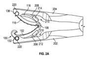
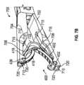
図2A~Bは、外科用クリップ100が装填された手動クリップアプライヤ200を示す。図示のように、クリップアプライヤ200は、外科用クリップ100を組織の上へ閉鎖及び/又は係止するために、互いに回転可能に結合された第1の顎部材202及び第2の顎部材204を含むことができる。第1の顎部材202は、第1の脚部材102の外面110を受け入れるよう、及び/又はこれと係合するように構成することができ、第2の顎部材204は、第2の脚部材104の外面114を受け入れるよう、及び/又はこれと係合するように構成することができる。図示のように、第1の顎部材202は、第1の脚部材102の外面110を受け入れるよう、及び/又はこれと係合するように構成された第1の可撓性部材206を含むことができ、第2の顎部材204は、第2の脚部材104の外面114を受け入れるよう、及び/又はこれと係合するように構成された第2の可撓性部材208を含むことができる。 2A-B depict a manual clip applier 200 loaded with a
可撓性部材206、208は、それぞれの第1及び第2の顎部材202、204の遠位部に据付け又は固定(例えば、溶接)された遠位部(例えば、図5A~Cに示すように516)を有することができる。可撓性部材206、208の遠位部は、それぞれの顎部材202、204の内側部の長手方向チャネル210に受け入れることができる。可撓性部材206、208の近位部は、クリップアプライヤ200へ直接取り付けられずに離間していてもよい。可撓性部材206、208は、外科用クリップ100の脚部材102、104を受け入れるよう、及び/又はこれと係合するように付勢されるばねベースの金属(例えば、ばね鋼)とすることができる。可撓性部材206、208は、第1及び第2の顎部材202、204が開放構成にある時、弓形の形状を有することができる。可撓性部材206、208は、第1及び第2の顎部材202、204が外科用クリップ100を閉鎖する時に、撓むように、及び/又はまっすぐになるように構成することができる。例えば、第1及び第2の顎部材202、204が外科用クリップ100を閉鎖する時に、可撓性部材206、208は、外科用クリップ100の撓みと、第1及び第2の顎部材102、104の接近とに適応するために、それぞれの顎部材202、204に向かって半径方向外側に撓む、及び/又は長手方向にまっすぐになる(伸びる)ことができる。 The
可撓性部材206、208は各々、第1及び第2の脚部材102、104を横方向に安定させるように構成された近位部に保持部材212、214を含むことができる。図示のように、保持部材212、214は各々、脚部材102、104を受け入れて外科用クリップ100の横方向の動きを防止又は低減するように構成された第1及び第2の対向側壁を含むことができる。保持部材212、214の各々は、それぞれの可撓性部材206、208と一体的に形成することができる。図2Bに更に示すように、第1及び第2の顎部材202、204の各々の長手方向チャネル210は、可撓性部材206、208のより狭い遠位部を受け入れるように構成されたより狭い部分と、第1及び第2の顎部材202、204が接近及び/又は閉鎖する時に保持部材212、214の幅を受け入れるように構成されたより広い部分と、を有することができる。従って、可撓性部材206、208は、クリップアプライヤが外科用クリップ100を閉鎖する時に、第1及び第2の顎部材202、204に嵌まり込むように構成することができる。可撓性部材206、208は、外科用クリップ100の閉鎖及び/又はロックを通して外科用クリップ100と係合する及び/又はこれを受け入れることができる。 Each of the
クリップアプライヤ200はまた、第1及び第2の脚部材102、104の遠位部を固定するように構成された第1及び第2の顎部材202、204の各遠位部に特徴部を含むことができる。例えば、図示するように、第1及び第2の顎部材202、204の各々は、外科用クリップ100のボス130~136を受け入れるように構成された少なくとも1つの溝220を含むことができる。更に図6B及び7Bに示すように、第1及び第2の顎部材202、204の各々は、チャネル210によって分離されてボス130~136を受け入れるように構成された第1及び第2の溝220を有することができる。 The clip applier 200 also includes features on the distal portions of each of the first and
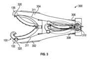
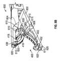
図3は、外科用クリップ100の1又は2以上が装填された自動クリップアプライヤ300を示す。クリップアプライヤ300は、組織の周りで外科用クリップ100を閉鎖及び/又はロックするように構成された第1及び第2の顎部材302、304を含むことができる。 FIG. 3 shows an
更に図示するように、クリップアプライヤ300は、第1及び第2の顎部材302、304と連通するチャネル308を有する細長いシャフト306を含むことができる。クリップアプライヤ300は、供給部(例えば、カートリッジ)からチャネル308を通して第1及び第2の顎部材302、304の間の位置に外科手術クリップ100を前進させるように構成されたフィーダ310を更に含むことができる。外科用クリップ100のほぼ対称な外面110、114は、チャネル308内に良好な嵌合を提供して、外科用クリップ100を垂直方向に整列させることができる。第2の脚部材104の外側部118は、細長いシャフト306の内面に接触することによって外科用クリップ100の前進を促進し、外科用クリップ100を垂直方向に安定させることができる。外科用クリップ100の嵌合は、外科用クリップ100の垂直方向への相対的な動きを防止するように設計されるフィーダ310の遠位端において小指を不要にすることができる。外科用クリップ100の凸状外面は、第1及び第2の顎部材302、304が係合する表面積を更に増加させて、第1及び第2の顎部材302、304の閉鎖中に外科用クリップ100の長さに沿ってより均一な圧縮を提供することができる。 As further illustrated, the
クリップアプライヤ300はまた、第1及び第2の脚部材102、104の遠位部を固定するように構成された第1及び第2の顎部材302、304の各遠位部に特徴部を含むことができる。例えば、図示するように、第1及び第2の顎部材302、304の各々は、外科用クリップ100のボス130~136を受け入れるように構成された少なくとも1つの溝320を含むことができる。また、外科用クリップ100の外面110、114を第1及び第2の顎部材302、304の凹状内面311に受け入れて、チャネル308から溝320内へのボス130~136の供給を促進することができる。 The
図4は、外科用クリップ400の背面斜視図を示す。外科用クリップ400は、外科用クリップ100(図1A~B)と同様の特徴を有することができる。同様の参照番号は、外科用クリップ100の同様の部分を指すとすることができる。 FIG. 4 shows a rear perspective view of
図示のように、外科用クリップ400は、近位部と遠位部とを有することができる。外科用クリップ400は、近位部及び遠位部を有する第1の脚部材402と、近位部及び遠位部を有する第2の脚部材404とを更に含むことができる。第1及び第2の脚部材402、404は、ヒンジ部材406によって近位部で一体的に接合することができる。 As shown,
第1及び第2の脚部材402、404は、湾曲部分を有する表面を含むことができる。例えば、第1の脚部材402は、第1の内面408と第1の外面410とを含むことができ、第2の脚部材404は、第2の内面412と第2の外面414とを含むことができる。第1の内面408は凹状湾曲を有することができ、第1の外面410は凸状湾曲を有することができる。第2の内面412は凸状湾曲を有することができ、第2の外面414は凸状湾曲を有することができる。第1の内面408の凹状湾曲及び/又は第1の外面410の凸状湾曲は、実質的に第1の脚部材402の全長にわたって延びることができる。第2の内面412の凸状湾曲及び/又は第2の外面414の凸状湾曲は、実質的に第2の脚部材404の全長にわたって延びることができる。内面408、412は、閉鎖構成で接近する又は接触することができる。また、第1の脚部材402は対向する側面を含むことができ、第2の脚部材404は対向する側面を含むことができる。 The first and
第2の脚部材404は、近位部420及び遠位部422で一体的に接合された内側部416(例えば、内側リブ)と外側部418(例えば、外側リブ)とを含むことができる。内側部416は、第2の内面412の少なくとも一部と凹状湾曲を備えた外面とを形成することができ、外側部418は、第2の外面414の少なくとも一部を形成し、凹状湾曲を備えた内面を有することができる。内側部416及び/又は外側部418の湾曲は、近位端(例えば、近位部420)から遠位端(例えば、遠位部422)まで延びることができる。内側部416及び外側部418の少なくとも一方は、第1の脚部材402の厚さよりも小さい厚さを有することができる。内側部416及び/又は外側部418のより小さな厚さは、より大きな可撓性を提供して、第2の内側表面412の種々の厚さの組織への撓みを可能にすることができる。内側部416、外側部418、及び/又は第1の脚部材402は、実質的に同じ曲率半径を有することができる。外科用クリップ400は、第1及び第2の脚部材402、404の凸状外面410、414により、長手方向軸に沿ってほぼ対称的な外形を有することができる。外科用クリップ400の全体的な対称性は、クリップアプライヤとの係合を容易にすることができる。 The second leg member 404 can include an inner portion 416 (eg, an inner rib) and an outer portion 418 (eg, an outer rib) joined together at a
内側部416及び外側部418は、第2の脚部材404の圧縮を可能にするために、第2の脚部材404の側面間に延びる少なくとも1つの横断アパーチャ又はチャネル424によって分離されるとすることができる。例えば、チャネル424は、内側部416を外側部418に向かって弾性的に押し付けることを可能にして組織の長さに沿って荷重を分配し、一方で外科用クリップ400内に組織をより効果的に把持して保持することができる。一部の実施形態では、内側部416、外側部418、及び/又はチャネル424は、第2の脚部材404の長さの4分の1を超えて延びることができる。一部の実施形態では、内側部416、外側部418、及び/又はチャネル424は、第2の脚部材404の長さの2分の1を超えて延びることができる。一部の実施形態では、内側部416、外側部418、及び/又はチャネル424は、実質的に第1の脚部材402の全長にわたって延びることができる。外側部418は、内側部416が閉鎖及び/又は係止中に屈曲して平らになる時に、可撓性を高めて内側部416の可撓性に関する拘束を低減するために、内側部416よりも小さい幅及び/又は厚さを有することができる。内側部416及び/又は外側部418は、製造を容易にするために、同じ材料で一体的に形成することができる(例えば、ポリマから射出成形される)。 The
第1の脚部材402の外面410は、長手方向突起部450を含むことができ、第2の脚部材404の外面414は、長手方向突起部452を含むことができる。長手方向突起部450、452は、クリップアプライヤと係合する及び/又はそれに受け入れられて、外科用クリップ400の横方向の動きを防止することができる。長手方向突起部450、452は、実質的にそれぞれの外面410、414の全長にわたって延びることができる。 The
ヒンジ部材406は、弾性的に可撓性であり、第1及び第2の脚部材402、404と一体的に形成することができる。ヒンジ部材406は、凹状の内面と凸状の外面とを有することができる。ヒンジ部材406の凹状内面は、第1の脚部材402の内面408と第2の脚部材404の内面412とを接合することができる。ヒンジ部材406の凸状外面は、第1の脚部材402の第1の外面410と第2の脚部材404の第2の外面414とを接合することができる。ヒンジ部材406はまた、ヒンジ部材406の可撓性を高めるために、ヒンジ表面間に位置する湾曲スロットを含むことができる。 The
外科用クリップ400はまた、1又は2以上の連動要素又は係止要素を有する係止機構を含むことができる。例えば、第1の脚部材402は、その遠位部でフック部材426に移行することができ、第2の脚部材404は、その遠位部で先端部材428に移行することができる。フック部材426の遠位部は、内方に湾曲し、ほぼヒンジ部材406の凹状内面の方に向いているとすることができる。フック部材426は、1又は2つ以上の横断傾斜面と、内面408と合わさって係止凹部を画定する凹状内面とを有することができる。先端部材428は、フック部材426が先端部材428の周りで撓む時に、傾斜面を受け入れるように構成されたスロットを画定するV字形とすることができる。フック部材426と先端部材428は、係合して係止機構を形成することができる。例えば、係止凹部は、外科用クリップ400を閉鎖構成に圧縮して血管又は他の組織の周りに固定する過程で先端部材428と係合することができる。
脚部材402、404は、クリップアプライヤの顎部材と係合するために、長さに沿って1又は2以上のボス430~436を含むことができる。例えば、第1の脚部材402は、その遠位部に隣接してフック部材426のすぐ近位にある対向側面の各々に対して垂直に突出するボス430、432を含むことができる。外科用クリップ400の図示する例では、ボス430、432は円柱形であって、第1の脚部材402の第1の外面410を越えて外方に突出することができる。ボス430、432はまた、ブリッジ部分431で互いに結合させることができる。第2の脚部材404も、その遠位部にボス434、436を含むことができる。ボス434、436は円柱状であり、第2の脚部材404の対向側面の各々に対して垂直に突出して、先端部材428の尖端の長手方向遠位に延びることができる。ボス434、436は、先端部材328のV字形スロットで分離されるとすることができる。クリップアプライヤの顎部材は、ボス430~436と係合し、脚部材402、404をヒンジ部材406の周りに回転させて、外科用クリップ400を圧縮して血管の周りで閉鎖及び/又は係止構成にすることができる。 The
外科用クリップ400は、第1の脚部材402の内面408に位置決めされた少なくとも1つの第1の歯状部440と、第2の脚部材404の内面412に位置決めされた少なくとも1つの第2の歯442とを含むことができる。例えば、外科用クリップ400は、第1の脚部材402の内面408に位置決めされた複数の第1の歯状部440と、第2の脚部材404の内面412に位置決めされた複数の第2の歯状部442とを含むことができる。 The
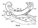
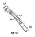
図5A~C、6A~B、及び7A~Bは、外科用クリップ400を適用するように構成された手動クリップアプライヤ500、600、700(以下、500~700)の様々な実施形態を示す。(外科用クリップ400を用いて図示するが、クリップアプライヤ500~700は、付加的に又は代替的に、外科用クリップ100と共に使用できることを容易に理解すべきである。)図示のように、クリップアプライヤ500~700は、外科用クリップ400を組織の上へ閉鎖及び/又は係止するために、互いに回転可能に結合された第1の顎部材502~702及び第2の顎部材504~704を含むことができる。第1の顎部材502~702は、第1の脚部材402の外面410を受け入れるよう、及び/又はこれと係合するように構成することができ、第2の顎部材504~704は、第2の脚部材404の外面414を受け入れるよう、及び/又はこれと係合するように構成することができる。図示のように、第1の顎部材502~702は、第1の脚部材402の外面410を受け入れるよう、及び/又はこれと係合するように構成された第1の可撓性部材506~706を含むことができ、第2の顎部材504~704は、第2の脚部材404の外面414を受け入れるよう、及び/又はこれと係合するように構成された第2の可撓性部材508~708を含むことができる。 5A-C, 6A-B, and 7A-B illustrate various embodiments of
可撓性部材506~706、508~708は、それぞれの第1及び第2の顎部材502~702、504~704の遠位部に据付け又は固定(例えば、溶接)された遠位部(例えば、図5A~Cに示すように516)を有することができる。可撓性部材506~706、508~708の遠位部は、それぞれの顎部材502~702、504~704の内側部の長手方向チャネル510~710に受け入れることができる。一部の実施形態では、図5A~Cに示すように、可撓性部材506、508は、自由近位部518を有することができる。近位部518は、クリップアプライヤ200への直接取付けがなく、離間しているとすることができる。近位部518は、長手方向チャネル510に受け入れられ、可撓性部材506、508が撓む及び/又はまっすぐになるに従って近位部518が並進する時の摩擦を低減するために、湾曲又はカールした先端を有することができる。一部の実施形態では、図6A~Cに示すように、可撓性部材606、608の近位部は、接続部620にて接合又は溶接することができる。一部の実施形態では、図7A~Bに示すように、可撓性部材706、708の近位部は、湾曲部722を備えて一体的に形成することができる。 The flexible members 506-706, 508-708 have distal portions (e.g., , 516) as shown in FIGS. 5A-C. The distal portions of the flexible members 506-706, 508-708 can be received in the longitudinal channels 510-710 of the inner portions of the respective jaw members 502-702, 504-704. In some embodiments, the
可撓性部材506~706、508~708は、外科用クリップ400の脚部材402、404を受け入れる及び/又はそれらと係合するように付勢されるばねベースの金属(例えば、ばね鋼)とすることができる。一部の実施形態では、可撓性部材506~706、508~708は、弓形の形状(例えば、図5A~5C及び6A~6B)を有することができ、或いは第1及び第2の顎部材502~702、504~704が開放構成にある時にまっすぐとなる(例えば、図7A~B)とすることができる。可撓性部材506~706、508~708は、第1及び第2の顎部材502~702、504~704が外科用クリップ400を閉鎖する時に、半径方向に撓む及び/又は長手方向にまっすぐになるように構成することができる。例えば、第1及び第2の顎部材502~702、504~704が外科用クリップ400を閉鎖する時に、可撓性部材506~706、508~708は、外科用クリップ400の撓みに適応するために、半径方向に撓む及び/又は長手方向にまっすぐになることができる。 The flexible members 506-706, 508-708 are spring-based metal (e.g., spring steel) biased to receive and/or engage the
可撓性部材506~706、508~708は各々、第1及び第2の脚部材402、404を横方向に安定させるように構成された保持部材を含むことができる。図示のように、保持部材は各々、長手方向突起部450、452に係合する及び/又はそれらを受け入れて、外科用クリップ400の装填、送出し、及び/又は閉鎖の間外科用クリップ400の横方向の動きを防止又は低減するように構成された長手方向スロット又はチャネル515~715を含むことができる。更に図示するように、可撓性部材506~706、508~708は、外科用クリップ400の幅に有利に対応する、減少させた実質的に均一な幅を有することができる。可撓性部材506~706、508~708はまた、第1及び第2の顎部材502~702、504~704が外科用クリップの上へ閉鎖する時に、長手方向チャネル510~710に受け入れられるとすることができる。可撓性部材506~706、508~708は、クリップアプライヤ200が外科用クリップ100を閉鎖する時に、第1及び第2の顎部材202、204に嵌まり込むように構成することができる。従って、可撓性部材506~706、508~708は、外科用クリップ400の閉鎖及び/又はロックを通して外科用クリップ400と係合する及び/又はこれを受け入れることができる。長手方向チャネル515~715は、クリップアプライヤ500~700が外科用クリップ400を閉鎖及び/又はロックする時に、長手方向突起部450、452を解放するように構成することができ、可撓性部材506~706、508~708の付勢により、クリップアプライヤ500~700が再び開かれる時に、外科用クリップ400は顎部材502~702、504~704から離れるように促されるとすることができる。 Each of the flexible members 506-706, 508-708 can include a retention member configured to laterally stabilize the first and
クリップアプライヤ500~700はまた、第1及び第2の脚部材402、404の遠位部を固定するように構成された第1及び第2の顎部材502~702、504~704の各遠位部に特徴部を含むことができる。例えば、図示するように、第1及び第2の顎部材502~702、504~704の各々は、外科用クリップ400のボス430~436を受け入れるように構成された少なくとも1つの溝520~720を含むことができる。更に図6B及び7Bに示すように、第1及び第2の顎部材502~702、504~704の各々は、チャネル510~710によって分離されてボス430~436を受け入れるように構成された第1及び第2の溝520~720を有することができる。 The clip applier 500-700 also includes a respective distal portion of the first and second jaw members 502-702, 504-704 configured to secure the distal portions of the first and
本発明の外科用クリップ100、400の様々な実施形態は、何れかの適切なサイズで製造することができ、血管、リンパ節、神経、卵管、又は心臓組織など、何れの数の組織にも適用することができる。外科用クリップ100、400の様々な実施形態は、金属及びポリマなど、何れかの適切な生体適合性材料から構成することができる。しかしながら、本発明は、ポリマクリップでの実行に特に適している。従って、外科用クリップ100、400の様々な実施形態は、外科用インプラントに一般に使用されるタイプなど、適切な強度の生体適合性エンジニアリングプラスチックから形成された一体型のポリマ本体から成ることが好ましい。例示的な材料には、ホモポリマ又はコポリマポリアセタール、ポリエチレンテレフタレート(PET)、ポリブチレンテレフタレート(PBT)、ポリオキシメチレン、或いは、射出成形、押出し成形、又は別な方法で加工して同様の物品にできる同様の特性を有する他の熱可塑性材料が含まれる。 Various embodiments of the
本発明の多くの特徴及び利点は詳細な明細書から明らかである。更に、数多くの変更形態及び変形形態が当業者には容易に見出されることになるので、本発明を図示し説明した正確な構造及び動作に限定することは望ましくなく、従って、全ての適切な変更形態及び等価物に対処可能であり、それらは本発明の範囲に入る。 Many features and advantages of the invention are apparent from the detailed specification. Furthermore, since numerous modifications and variations will readily occur to those skilled in the art, it is not desirable to limit the invention to the precise structure and operation shown and described, and therefore all suitable modifications may be made. Forms and equivalents are possible and fall within the scope of this invention.
100 外科用クリップ
102 第1の脚部材
104 第2の脚部材
106 ヒンジ部材
108 第1の内面
110 第1の外面
112 第2の内面
114 第2の外面
116 内側部
118 外側部
120 近位部
122 遠位部
124 横断アパーチャ又はチャネル
126 フック部材
128 先端部材
130 ボス
134 ボス
140 歯状部
142 歯状部100
Claims (15)
Translated fromJapanese第1のスロットが形成された第1の可撓性部材を備える第1の顎部材と、第2のスロットが形成された第2の可撓性部材を備える第2の顎部材と、を有するクリップアプライヤと、
組織を結紮するように構成された外科用クリップであって、第1の近位部、第1の遠位部、第1の内面、及び凸状湾曲を有する第1の外面を含む第1の脚部材と、第2の近位部、第2の遠位部、第2の内面、及び第2の外面を含む第2の脚部材と、を有する外科用クリップと、
を備え、
更に、前記第2の脚部材は、チャネルによって分離されポリマで一体的に形成された内側部と外側部とを含み、前記チャネルは、前記第2の脚部材の対向する側面の間に延び、前記第2の内面は、前記第2の近位部から前記第2の遠位部へ延びる凸状湾曲を有し、前記第2の外面は、前記外側部に形成され且つ凸状湾曲を有し、
前記第1の脚部材は、前記クリップアプライヤの前記第1の可撓性部材の前記第1のスロットに係合するように構成された第1の長手方向突起部を備え、前記第2の脚部材は、前記クリップアプライヤの前記第2の可撓性部材の前記第2のスロットに係合するように構成された第2の長手方向突起部を備えている、組立体。An assembly for ligating tissue, the assembly comprising:
a first jaw membercomprising a first flexible member having a first slot formed therein ; and a second jawmember comprising a second flexible member having a second slot formed therein. clip applier and
A surgical clip configured to ligate tissue, the surgical clip including a first proximal portion, a first distal portion, a first inner surface, and a first outer surface having a convex curvature. a surgical clip having a leg member and a second leg member including a second proximal portion, a second distal portion, a second inner surface, and a second outer surface;
Equipped with
Further, the second leg member includes an inner portion and an outer portion integrally formed of a polymer separated by a channel, the channel extending between opposing sides of the second leg member; The second inner surface has a convex curvature extending from the second proximal portion to the second distal portion, and the second outer surface is formed on the outer portion and has a convex curvature. death,
The first leg member includes a first longitudinal projection configured to engage the first slot ofthe first flexible member of the clip applier; The leg member includesa second longitudinal protrusion configured to engage the second slot of the second flexible member of the clip applier.
第1のスロットが形成された第1の可撓性部材を備える第1の顎部材と、第2のスロットが形成された第2の可撓性部材を備える第2の顎部材と、を有するクリップアプライヤと、
組織を結紮するように構成された外科用クリップであって、
第1の近位部、第1の遠位部、凹状湾曲を有する第1の内面、及び凸状湾曲を有する第1の外面、を含む第1の脚部材と、
第2の近位部、第2の遠位部、第2の内面、及び第2の外面、を含む第2の脚部材であって、更に、前記第2の脚部材は、チャネルによって分離された内側部と外側部とを含み、前記チャネルは、前記第2の脚部材の対向する側面の間に延び、前記第2の内面は、前記内側部に形成されて前記第2の近位部から前記第2の遠位部へ延びる凸状湾曲を有し、前記第2の外面は、前記外側部に形成されて凸状湾曲を有し、前記内側部と前記外側部がポリマから一体的に形成される第2の脚部材と、
前記第1の近位部と前記第2の近位部とを回転可能に結合するヒンジ部材と、
前記第1の脚部材の前記第1の遠位部にあるフック部材と、
前記第2の脚部材の前記第2の遠位部にある先端部材であって、前記フック部材は、閉鎖構成において前記先端部材の周りに撓んで前記外科用クリップを固定するように構成される先端部材と、
を有する外科用クリップと、
を備え、
前記第1の脚部材は、前記クリップアプライヤの前記第1の可撓性部材の前記第1のスロットに係合するように構成された第1の長手方向突起部を備え、前記第2の脚部材は、前記クリップアプライヤの前記第2の可撓性部材の前記第2のスロットに係合するように構成された第2の長手方向突起部を備えている、組立体。An assembly for ligating tissue, the assembly comprising:
a first jaw membercomprising a first flexible member having a first slot formed therein ; and a second jawmember comprising a second flexible member having a second slot formed therein. clip applier and
A surgical clip configured to ligate tissue, the clip comprising:
a first leg member including a first proximal portion, a first distal portion, a first inner surface having a concave curvature, and a first outer surface having a convex curvature;
a second leg member including a second proximal portion, a second distal portion, a second inner surface, and a second outer surface, the second leg members further separated by a channel; an inner portion and an outer portion, the channel extending between opposing sides of the second leg member, and the second inner surface formed in the inner portion and the second proximal portion. and a convex curvature extending from the outer portion to the second distal portion, the second outer surface having a convex curvature formed on the outer portion, and the inner portion and the outer portion being integrally formed from a polymer. a second leg member formed in;
a hinge member that rotatably couples the first proximal portion and the second proximal portion;
a hook member at the first distal portion of the first leg member;
a tip member on the second distal portion of the second leg member, the hook member being configured to deflect about the tip member in a closed configuration to secure the surgical clip; a tip member;
a surgical clip having a
Equipped with
The first leg member includes a first longitudinal projection configured to engage the first slot ofthe first flexible member of the clip applier; The leg member includesa second longitudinal protrusion configured to engage the second slot of the second flexible member of the clip applier.
第1の顎部材と第2の顎部材とを有するクリップアプライヤと、
前記クリップアプライヤに装填される外科用クリップと、
を備え、
前記外科用クリップは、第1の近位部、第1の遠位部、第1の内面、及び前記第1の顎部材と係合する凸状湾曲を有する第1の外面、を含む第1の脚部材と、第2の近位部、第2の遠位部、第2の内面、及び第2の外面、を含む第2の脚部材と、を備え、
更に、前記第2の脚部材は、チャネルによって分離されポリマで一体的に形成された内側部と外側部とを含み、前記チャネルは、前記第2の脚部材の圧縮を可能にするために前記第2の脚部材の対向する側面の間に延び、前記第2の内面は、前記第2の近位部から前記第2の遠位部へ延びる凸状湾曲を有し、前記第2の外面は、外側部に形成されて、前記第2の顎部材と係合する凸状湾曲を有し、
前記クリップアプライヤの前記第1の顎部材は、前記外科用クリップの前記第1の脚部材と係合するように構成された第1の可撓性部材を備え、前記クリップアプライヤの前記第2の顎部材は、前記外科用クリップの前記第2の脚部材と係合するように構成された第2の可撓性部材を備えている、
クリップアプライヤシステム。A clip applier system configured to ligate tissue, the clip applier system comprising:
a clip applier having a first jaw member and a second jaw member;
a surgical clip loaded into the clip applier;
Equipped with
The surgical clip includes a first proximal portion, a first distal portion, a first inner surface, and a first outer surface having a convex curvature for engaging the first jaw member. a second leg member including a second proximal portion, a second distal portion, a second inner surface, and a second outer surface;
Further, the second leg member includes an inner portion and an outer portion integrally formed of a polymer separated by a channel, the channel including a extending between opposing sides of a second leg member, the second inner surface having a convex curvature extending from the second proximal portion to the second distal portion; has a convex curvature formed on an outer portion to engage the second jaw member;
The first jaw member of the clip applier includes a first flexible member configured to engage the first leg member of the surgical clip; the second jaw member includes a second flexible member configured to engage the second leg member of the surgical clip;
Clip applier system.
Priority Applications (1)
| Application Number | Priority Date | Filing Date | Title |
|---|---|---|---|
| JP2023074750AJP2023086973A (en) | 2017-03-21 | 2023-04-28 | surgical clips and clip applier |
Applications Claiming Priority (5)
| Application Number | Priority Date | Filing Date | Title |
|---|---|---|---|
| US201762474538P | 2017-03-21 | 2017-03-21 | |
| US62/474,538 | 2017-03-21 | ||
| US201862627536P | 2018-02-07 | 2018-02-07 | |
| US62/627,536 | 2018-02-07 | ||
| PCT/US2018/023600WO2018175610A1 (en) | 2017-03-21 | 2018-03-21 | Surgical clip and clip applier |
Related Child Applications (1)
| Application Number | Title | Priority Date | Filing Date |
|---|---|---|---|
| JP2023074750ADivisionJP2023086973A (en) | 2017-03-21 | 2023-04-28 | surgical clips and clip applier |
Publications (2)
| Publication Number | Publication Date |
|---|---|
| JP2020511268A JP2020511268A (en) | 2020-04-16 |
| JP7416624B2true JP7416624B2 (en) | 2024-01-17 |
Family
ID=63581955
Family Applications (2)
| Application Number | Title | Priority Date | Filing Date |
|---|---|---|---|
| JP2019552082AActiveJP7416624B2 (en) | 2017-03-21 | 2018-03-21 | surgical clips and clip appliers |
| JP2023074750APendingJP2023086973A (en) | 2017-03-21 | 2023-04-28 | surgical clips and clip applier |
Family Applications After (1)
| Application Number | Title | Priority Date | Filing Date |
|---|---|---|---|
| JP2023074750APendingJP2023086973A (en) | 2017-03-21 | 2023-04-28 | surgical clips and clip applier |
Country Status (5)
| Country | Link |
|---|---|
| US (2) | US11607227B2 (en) |
| EP (1) | EP3600082A4 (en) |
| JP (2) | JP7416624B2 (en) |
| CN (2) | CN110740695B (en) |
| WO (1) | WO2018175610A1 (en) |
Families Citing this family (41)
| Publication number | Priority date | Publication date | Assignee | Title |
|---|---|---|---|---|
| CN116784923A (en) | 2017-03-21 | 2023-09-22 | 泰利福医疗公司 | Clip applier with stabilizing member |
| JP6873267B2 (en) | 2017-03-21 | 2021-05-19 | テレフレックス メディカル インコーポレイテッド | Clip applier with stabilizer |
| US12023041B2 (en) | 2017-03-21 | 2024-07-02 | Teleflex Medical Incorporated | Clip applier |
| JP7159189B2 (en) | 2017-03-21 | 2022-10-24 | テレフレックス メディカル インコーポレイテッド | Flexible stabilizing member for clip applier |
| CA3068282C (en) | 2017-06-22 | 2022-06-28 | Teleflex Medical Incorporated | Surgical clip |
| US20190133590A1 (en) | 2017-11-03 | 2019-05-09 | Covidien Lp | Ligation clip with controlled tissue compression |
| JP6986789B2 (en)* | 2017-11-10 | 2021-12-22 | エンジェクス ファーマシューティカル インコーポレイテッド | Compounds, pharmaceutically acceptable salts thereof, use of compounds and pharmaceutical compositions. |
| ES2981210T3 (en) | 2017-11-14 | 2024-10-07 | Teleflex Medical Inc | Surgical clip |
| US10932788B2 (en) | 2018-04-11 | 2021-03-02 | Covidien Lp | Ligation clip with latching and retention features |
| US10932789B2 (en) | 2018-04-11 | 2021-03-02 | Covidien Lp | Ligation clip with latching and retention features |
| US11033279B2 (en) | 2018-04-24 | 2021-06-15 | Covidien Lp | Ligation clip with retention features |
| US11304703B2 (en) | 2018-05-25 | 2022-04-19 | Covidien Lp | Ligation clip removal device |
| KR102092347B1 (en)* | 2018-07-16 | 2020-03-23 | 주식회사 엔도비전 | Banana clip for removing hemorrhoids and Surgical tool set including the same |
| KR102647625B1 (en)* | 2018-07-18 | 2024-03-14 | 텔리플렉스 메디컬 인코포레이티드 | Clip Appliers and Cartridges |
| US11317923B2 (en) | 2018-08-13 | 2022-05-03 | Covidien Lp | Ligation clip with improved hinge |
| US11304704B2 (en) | 2018-08-22 | 2022-04-19 | Covidien Lp | Surgical clip applier and ligation clips |
| JP7247330B2 (en) | 2018-09-26 | 2023-03-28 | テレフレックス メディカル インコーポレイテッド | Clip applier with stabilizing member |
| TWI675642B (en)* | 2018-10-24 | 2019-11-01 | 台灣先進手術醫療器材股份有限公司 | Clip applier |
| KR102852635B1 (en)* | 2018-11-16 | 2025-08-29 | 텔리플렉스 메디컬 인코포레이티드 | Surgical clip |
| US11471165B2 (en) | 2019-05-08 | 2022-10-18 | Covidien Lp | Ligation clip cartridge |
| JP2021007570A (en)* | 2019-06-29 | 2021-01-28 | 株式会社三洋物産 | Game machine |
| US11707282B2 (en) | 2019-07-02 | 2023-07-25 | Covidien Lp | Multi-piece ligation clip |
| US20210030420A1 (en)* | 2019-08-02 | 2021-02-04 | Covidien Lp | Ligation clip with improved latch mechanism |
| USD907204S1 (en) | 2019-08-02 | 2021-01-05 | Covidien Lp | Ligation clip |
| USD907203S1 (en) | 2019-08-02 | 2021-01-05 | Covidien Lp | Ligation clip |
| US11395660B2 (en) | 2019-08-05 | 2022-07-26 | Covidien Lp | Stackable ligation clip |
| USD907200S1 (en) | 2019-08-05 | 2021-01-05 | Covidien Lp | Ligation clip |
| US20210068840A1 (en)* | 2019-09-06 | 2021-03-11 | Covidien Lp | Energizable surgical clip applier |
| WO2021062170A1 (en) | 2019-09-26 | 2021-04-01 | Teleflex Medical Incorporated | Clip applier |
| EP4076216A1 (en) | 2019-12-19 | 2022-10-26 | Teleflex Medical Incorporated | Surgical clip |
| US11696764B2 (en) | 2020-01-31 | 2023-07-11 | Covidien Lp | Ligation clip with controlled tissue compression |
| JP2021133200A (en)* | 2020-02-28 | 2021-09-13 | 株式会社三洋物産 | Pachinko machine |
| JP2021133199A (en)* | 2020-02-28 | 2021-09-13 | 株式会社三洋物産 | Pachinko machine |
| JP2021133198A (en)* | 2020-02-28 | 2021-09-13 | 株式会社三洋物産 | Pachinko machine |
| US12114866B2 (en) | 2020-03-26 | 2024-10-15 | Covidien Lp | Interoperative clip loading device |
| JP2021186294A (en)* | 2020-05-29 | 2021-12-13 | 株式会社三洋物産 | Game machine |
| JP2022012090A (en)* | 2020-06-30 | 2022-01-17 | 株式会社三洋物産 | Game machine |
| JP2022012089A (en)* | 2020-06-30 | 2022-01-17 | 株式会社三洋物産 | Game machine |
| JP2022012088A (en)* | 2020-06-30 | 2022-01-17 | 株式会社三洋物産 | Game machine |
| CN112006748B (en)* | 2020-08-29 | 2022-05-06 | 江苏省肿瘤医院 | Curved forceps for minimally invasive surgery vagina |
| CN114680994A (en)* | 2020-12-31 | 2022-07-01 | 江苏风和医疗器材股份有限公司 | a clamp |
Citations (4)
| Publication number | Priority date | Publication date | Assignee | Title |
|---|---|---|---|---|
| US3867944A (en) | 1972-10-27 | 1975-02-25 | Wood Ernest C | Hemostatic clip and applicator therefor |
| GB2054027A (en) | 1979-06-18 | 1981-02-11 | Ethicon Inc | Plastic ligating clips |
| CN105054989A (en) | 2015-07-03 | 2015-11-18 | 桐庐洲济医疗器械有限公司 | Disposable vascular clamp |
| CN106264646A (en) | 2016-08-29 | 2017-01-04 | 张大宏 | Strongly run-resistant hemostatic clamp |
Family Cites Families (287)
| Publication number | Priority date | Publication date | Assignee | Title |
|---|---|---|---|---|
| US929868A (en) | 1908-09-17 | 1909-08-03 | Carl L Mueller | Detachable-jaw tool. |
| US1482290A (en) | 1921-02-02 | 1924-01-29 | Elzi Peter Frank | Bending tool |
| US1728322A (en) | 1928-02-22 | 1929-09-17 | Badrian Max | Device for elastically clamping off the male urethra |
| US2384697A (en) | 1944-10-18 | 1945-09-11 | Riccardi Peter | Umbilical clip |
| US2635238A (en) | 1949-07-11 | 1953-04-21 | Garland Mather | Apparatus for clamping umbilical cords and the like |
| US2626608A (en) | 1949-12-08 | 1953-01-27 | Garland Mather | Clamp for umbilical cords and the like |
| US2598901A (en) | 1950-03-10 | 1952-06-03 | Garland Mather | Clamp for constricting flexible tubular elements and the like |
| US2594102A (en) | 1950-05-03 | 1952-04-22 | Vollmer Leonhard | Automatic inserter for suturing clips |
| US2744251A (en) | 1953-06-04 | 1956-05-08 | Vollmer Leonhard | Automatic inserter for suturing clips |
| US2881762A (en) | 1955-02-09 | 1959-04-14 | Robert J Lowrie | Surgical staple and stapler |
| US2890519A (en) | 1955-08-01 | 1959-06-16 | Storz Instr Co | Surgical spring clip forceps |
| US2813269A (en) | 1956-01-25 | 1957-11-19 | Jacobs John Bay | Implement for applying an umbilical cord seal and identifying newly born babies |
| US2814222A (en) | 1956-07-16 | 1957-11-26 | Emmitt G Sanders | Ferrule crimping pliers with replaceable jaws |
| US3032039A (en) | 1959-05-26 | 1962-05-01 | Jack O Beaty | Arterial and veinous clamp and clamp applicator |
| US3150379A (en) | 1962-03-01 | 1964-09-29 | Ernest C Wood | Single clip disposable applicator |
| US3172133A (en) | 1962-05-14 | 1965-03-09 | Olympio C Rizzo | Long nose pliers with cutting attachment |
| US3463156A (en) | 1965-05-27 | 1969-08-26 | Edward B Mcdermott | Hemostatic clip and applicator |
| US3446212A (en) | 1965-07-19 | 1969-05-27 | New Research & Dev Lab Inc | Hemostatic clip and applicator therefor |
| US3503398A (en) | 1965-09-10 | 1970-03-31 | American Hospital Supply Corp | Atraumatic clamp for vascular surgery |
| US3503397A (en) | 1967-09-21 | 1970-03-31 | American Hospital Supply Corp | Atraumatic surgical clamp |
| US3503396A (en) | 1967-09-21 | 1970-03-31 | American Hospital Supply Corp | Atraumatic surgical clamp |
| US3766925A (en) | 1971-05-25 | 1973-10-23 | Eljay Hospital Prod Corp | Surgical clamp with cam-action lever |
| US3827438A (en) | 1972-07-10 | 1974-08-06 | G Kees | Aneurysm clip |
| US3954108A (en) | 1972-11-03 | 1976-05-04 | Davis Hugh J | Occlusion clip and instrument for applying same |
| US3874042A (en) | 1973-01-22 | 1975-04-01 | Biospectrum Inc | Clamp for thin walled tubing |
| US3825012A (en) | 1973-04-13 | 1974-07-23 | H Nicoll | Reusable umbilical cord clamp for veterinary use |
| DE2730691C2 (en) | 1976-07-16 | 1982-12-16 | Maruho Co. Ltd., Osaka | Surgical clip, connecting element for several surgical clips and forceps for opening and closing the same |
| US4120302A (en) | 1976-10-08 | 1978-10-17 | American Hospital Supply Corporation | Disposable pads for surgical instruments |
| CA1082552A (en) | 1977-08-05 | 1980-07-29 | Charles H. Klieman | Hemostatic clip applicator |
| US4316468A (en) | 1977-08-05 | 1982-02-23 | Charles H. Klieman | Surgical stapler |
| US4337774A (en) | 1978-06-14 | 1982-07-06 | Metatech Corporation | Micro surgical clip |
| US4428374A (en) | 1978-12-20 | 1984-01-31 | Auburn Robert M | Umbilical cord clamping assembly |
| US4390019A (en) | 1979-02-28 | 1983-06-28 | Leveen Harry H | Blood vessel clamp |
| US4418694A (en) | 1979-06-18 | 1983-12-06 | Ethicon, Inc. | Non-metallic, bio-compatible hemostatic clips |
| US4527562A (en) | 1979-06-18 | 1985-07-09 | Ethicon, Inc. | Non-metallic, bio-compatible hemostatic clips |
| MX151148A (en) | 1980-02-25 | 1984-10-04 | Johnson & Johnson | IMPROVEMENTS IN HEMOSTATIC FORCEPS |
| US4638804A (en) | 1980-02-25 | 1987-01-27 | Ethicon, Inc. | Double-latched non-metallic, bio-compatible hemostatic clip |
| US4345600A (en) | 1980-08-04 | 1982-08-24 | Senco Products, Inc. | Purse-stringer |
| US4414721A (en) | 1980-11-07 | 1983-11-15 | Hufnagel Charles A | Occlusive clip and applicator for constricting flexible tubular members |
| US4346869A (en) | 1981-03-12 | 1982-08-31 | Macneill Robert L | Tube clamp |
| US4394864A (en) | 1981-04-15 | 1983-07-26 | Jeffrey Sandhaus | Apparatus and method for effecting occlusion of the vas deferens |
| US4550729A (en) | 1981-08-27 | 1985-11-05 | Ethicon, Inc. | Non-metallic, bio-compatible hemostatic clips with interlocking latch means |
| US4570633A (en) | 1981-09-28 | 1986-02-18 | Ethicon, Inc. | Surgical clip applier instrument adapter jaws |
| US4487204A (en) | 1981-10-14 | 1984-12-11 | Nomel | Device for applying haemostatic clips |
| US4471780A (en) | 1982-02-05 | 1984-09-18 | Ethicon, Inc. | Multiple ligating clip applier instrument |
| US4476865A (en) | 1982-02-12 | 1984-10-16 | Ethicon, Inc. | Non-metallic, bio-compatible hemostatic clips |
| US4450840A (en) | 1982-02-26 | 1984-05-29 | Ethicon, Inc. | Ligating clip with flanged base having a recessed engaging face |
| US4487205A (en) | 1982-04-26 | 1984-12-11 | Ethicon, Inc. | Non-metallic, bio-compatible hemostatic clips |
| US4458682A (en) | 1982-08-02 | 1984-07-10 | Ethicon, Inc. | Non-metallic, bio-compatible hemostatic clips (ring lock clips) |
| US4671281A (en) | 1982-09-13 | 1987-06-09 | Ethicon, Inc. | Non-metallic, bio-compatible hemostatic clips (one piece wedge clip) |
| US4492232A (en) | 1982-09-30 | 1985-01-08 | United States Surgical Corporation | Surgical clip applying apparatus having fixed jaws |
| US4519392A (en) | 1982-10-12 | 1985-05-28 | Lingua Robert W | Hemostasing muscle clips for needleless surgery |
| US4534351A (en) | 1982-10-20 | 1985-08-13 | Senmed, Inc. | Ligator |
| US4444187A (en) | 1982-12-09 | 1984-04-24 | Metatech Corporation | Miniature surgical clip for clamping small blood vessels in brain surgery and the like |
| US4579118A (en) | 1983-06-01 | 1986-04-01 | Ethicon, Inc. | Hemostatic clip with penetration means |
| US4919152A (en) | 1987-03-02 | 1990-04-24 | Ralph Ger | Method of closing the opening of a hernial sac |
| US5127915A (en) | 1984-10-29 | 1992-07-07 | Mattson Philip D | Surgical instrument for severing and clamping an umbilical cord |
| US4589626A (en) | 1985-03-13 | 1986-05-20 | Bioresearch Inc. | Hose clamp |
| US4588160A (en) | 1985-03-27 | 1986-05-13 | Sherwood Medical Company | Tube clamping device |
| US4616651A (en) | 1985-04-15 | 1986-10-14 | Ethicon, Inc. | Surgical clip applier instrument adapter jaws |
| JPH0657218B2 (en) | 1985-05-10 | 1994-08-03 | エチコン・インコ−ポレ−テツド | Ligation clip and clip application device |
| US4712549A (en) | 1985-07-01 | 1987-12-15 | Edward Weck & Co. | Automatic hemostatic clip applier |
| US5047038A (en) | 1985-07-01 | 1991-09-10 | Edward Weck Incorporated | Automatic hemostatic clip applier |
| US4807622A (en) | 1985-09-20 | 1989-02-28 | Kato Hatsujo Kaisha, Ltd. | Tube cutting and separating implement for conduit of blood or the like |
| US4924864A (en) | 1985-11-15 | 1990-05-15 | Danzig Fred G | Apparatus and article for ligating blood vessels, nerves and other anatomical structures |
| US4686983A (en) | 1986-04-08 | 1987-08-18 | Gerald Leisman | Apparatus and method for ligating a body vessel |
| US4716886A (en) | 1986-05-01 | 1988-01-05 | Norman Schulman | Umbilical cord clamp and cutters |
| US4726372A (en) | 1986-09-19 | 1988-02-23 | Metatech Corporation | Hemostatic clip |
| DE3704760C1 (en) | 1987-02-16 | 1988-03-03 | Aesculap Werke Ag | Application device for C-shaped scalp clips |
| US4834090A (en) | 1987-03-02 | 1989-05-30 | Moore J Paul | Suture boot |
| US4822348A (en) | 1987-05-13 | 1989-04-18 | Donn Casey | Surgical clips |
| JPH07106416B2 (en) | 1987-09-21 | 1995-11-15 | 旭テック株式会社 | Vehicle wheel manufacturing method |
| US4834096A (en) | 1987-10-26 | 1989-05-30 | Edward Weck Incorporated | Plastic ligating clips |
| GB2212201B (en) | 1987-11-10 | 1992-06-03 | Donn Casey | Surgical clip |
| US4870965A (en)* | 1988-03-04 | 1989-10-03 | Jahanger Mohammed S | Umbilical cord cutting and clamping device |
| US5053045A (en)* | 1988-09-16 | 1991-10-01 | Schmidt Ferenc J | Surgical clip |
| US4942886A (en) | 1989-02-22 | 1990-07-24 | Timmons John W | External incontinency device |
| US5062846A (en) | 1989-03-28 | 1991-11-05 | Edward Weck Incorporated | Penetrating plastic ligating clip |
| US4976722A (en) | 1989-05-22 | 1990-12-11 | Ethicon, Inc. | Surgical hemostatic clips |
| US4938764A (en) | 1989-06-02 | 1990-07-03 | John Glaberson | Tick remover |
| US4938765A (en) | 1989-06-22 | 1990-07-03 | Life Centers, Inc. | Surgical silicon loops |
| US5104395A (en) | 1989-07-03 | 1992-04-14 | Edward Weck Incorporated | Automatic hemostatic clip applicator |
| US4950275A (en) | 1989-07-19 | 1990-08-21 | Cyanamid Italia S.P.A. | Bowel-anastomosis-ring holder pincers |
| US4972949A (en) | 1989-09-26 | 1990-11-27 | Horizon Surgical, Inc. | Hemostatic clip holder for small clips |
| US4936447A (en) | 1989-09-26 | 1990-06-26 | Horizon Surgical Inc. | Hemostatic clip holder |
| US5100416A (en)* | 1989-10-17 | 1992-03-31 | Edward Weck Incorporated | Ligating clip applying instrument |
| US5009657A (en) | 1989-12-14 | 1991-04-23 | Mohammed S. Jahanger | Umbilical cord cutting and clamping device |
| US4961499A (en) | 1990-01-04 | 1990-10-09 | Pilling Co. | Hemostatic clip cartridge |
| NZ233737A (en) | 1990-05-18 | 1992-12-23 | Allflex New Zealand | Applicator for one-piece ear tag formed into an annulus |
| US5078731A (en) | 1990-06-05 | 1992-01-07 | Hayhurst John O | Suture clip |
| US5207692A (en) | 1990-07-30 | 1993-05-04 | Codman & Shurtleff, Inc. | Surgical clip applier with reciprocating clip sleeve and dual ratchet mechanism |
| US5026382A (en) | 1990-08-27 | 1991-06-25 | Horizon Surgical, Inc. | Hemostatic clip |
| US5201416A (en) | 1990-10-22 | 1993-04-13 | Edward Weck Incorporated | Hemostatic clip cartridge |
| US5046611A (en) | 1990-10-22 | 1991-09-10 | Edward Weck Incorporated | Hemostatic clip cartridge |
| US5366458A (en) | 1990-12-13 | 1994-11-22 | United States Surgical Corporation | Latchless surgical clip |
| US5171252A (en) | 1991-02-05 | 1992-12-15 | Friedland Thomas W | Surgical fastening clip formed of a shape memory alloy, a method of making such a clip and a method of using such a clip |
| US5112343A (en) | 1991-04-05 | 1992-05-12 | Edward Weck Incorporated | Endoscopic clip appliers |
| US5160339A (en) | 1991-06-18 | 1992-11-03 | Ethicon, Inc. | Endoscopic suture clip |
| US5163945A (en) | 1991-10-18 | 1992-11-17 | Ethicon, Inc. | Surgical clip applier |
| US5259405A (en) | 1992-01-29 | 1993-11-09 | Hua Chou Kuo | Structure of a barette |
| US5171251A (en) | 1992-03-02 | 1992-12-15 | Ethicon, Inc. | Surgical clip having hole therein and method of anchoring suture |
| US5246450A (en) | 1992-03-10 | 1993-09-21 | Edward Weck Incorporated | High capacity medical clip feeding and dispensing mechanism |
| US5279416A (en) | 1992-06-05 | 1994-01-18 | Edward Weck Incorporated | Ligating device cartridge with separable retainer |
| US5234449A (en) | 1992-07-16 | 1993-08-10 | Ethicon, Inc. | Suture clip with reduced hinge mass |
| US5330442A (en) | 1992-10-09 | 1994-07-19 | United States Surgical Corporation | Suture retaining clip |
| CA2107635C (en) | 1992-10-09 | 1999-08-17 | David T. Green | Surgical clip applier |
| US5464416A (en) | 1992-11-10 | 1995-11-07 | Ethicon, Inc. | Ligating clip |
| US5330487A (en) | 1992-12-17 | 1994-07-19 | Tfi Acquistion Corp. | Drive mechanism for surgical instruments |
| US5569274A (en) | 1993-02-22 | 1996-10-29 | Heartport, Inc. | Endoscopic vascular clamping system and method |
| CA2120828C (en) | 1993-04-16 | 1999-11-02 | Paul J. Phillips | Surgical hemostatic clip |
| US5431668A (en) | 1993-04-29 | 1995-07-11 | Ethicon, Inc. | Ligating clip applier |
| US5549621A (en) | 1993-05-14 | 1996-08-27 | Byron C. Sutherland | Apparatus and method for performing vertical banded gastroplasty |
| DK110193A (en) | 1993-09-30 | 1995-03-31 | Per Baunsgaard | Terminal device |
| US5405344A (en) | 1993-09-30 | 1995-04-11 | Ethicon, Inc. | Articulable socket joint assembly for an endoscopic instrument for surgical fastner track therefor |
| US5607436A (en) | 1993-10-08 | 1997-03-04 | United States Surgical Corporation | Apparatus for applying surgical clips |
| US5462555A (en) | 1993-12-30 | 1995-10-31 | United States Surgical Corporation | Umbilical cord clip and applicator |
| GB9400739D0 (en) | 1994-01-15 | 1994-03-16 | Femcare Ltd | Medical clip |
| US5501693A (en) | 1994-07-06 | 1996-03-26 | United States Surgical Corporation | Surgical hemostatic clip |
| US5626585A (en) | 1994-09-16 | 1997-05-06 | United States Surgical Corporation | Ligating clip advance |
| US5487746A (en) | 1994-11-23 | 1996-01-30 | Yu; George W. | Surgical clip having a longitudinal opening through which clamped tissue protrudes |
| US5695505A (en) | 1995-03-09 | 1997-12-09 | Yoon; Inbae | Multifunctional spring clips and cartridges and applicators therefor |
| US5667516A (en) | 1995-05-01 | 1997-09-16 | Allen; Sean A. | Mechanism for cutting an umbilical cord |
| US5575796A (en) | 1995-05-17 | 1996-11-19 | Utah Medical Products, Inc. | Umbilical cord cutter and sampler |
| US5908430A (en) | 1995-06-07 | 1999-06-01 | Appleby; Timothy | Easy loading hemostatic clip and cartridge |
| US5713912A (en) | 1995-08-30 | 1998-02-03 | Stress Management, Inc. | Ligating clip having ramp-shaped vessel clamping members and tool for applying same |
| US5810853A (en) | 1996-01-16 | 1998-09-22 | Yoon; Inbae | Knotting element for use in suturing anatomical tissue and methods therefor |
| US6015417A (en) | 1996-01-25 | 2000-01-18 | Reynolds, Jr.; Walker | Surgical fastener |
| US5846255A (en) | 1996-01-31 | 1998-12-08 | Casey Medical Products Limited | Surgical clip |
| DE19603889C2 (en) | 1996-02-03 | 1999-05-06 | Aesculap Ag & Co Kg | Surgical application device |
| US5797922A (en) | 1996-02-06 | 1998-08-25 | Balagan Medical Inc. | Umbilical cord clamping device |
| WO1997038634A1 (en) | 1996-04-18 | 1997-10-23 | Applied Medical Resources Corporation | Malleable clip applier and method |
| US5925052A (en) | 1996-06-26 | 1999-07-20 | Simmons; Paul L. | Umbilical surgical scissors |
| US5722982A (en) | 1996-09-26 | 1998-03-03 | University Technology Corporation | Strabismus surgery apparatus and method |
| US5713911A (en) | 1996-10-03 | 1998-02-03 | United States Surgical Corporation | Surgical clip |
| US5954731A (en) | 1997-07-29 | 1999-09-21 | Yoon; Inbae | Surgical instrument with multiple rotatably mounted spreadable end effectors |
| US5972003A (en) | 1997-10-01 | 1999-10-26 | Sherwood Services Ag | Single-free ligation clip module |
| US5921991A (en) | 1997-10-23 | 1999-07-13 | Biomax Technologies Inc. | Multi-colored umbilical cord clamp |
| US6050996A (en) | 1997-11-12 | 2000-04-18 | Sherwood Services Ag | Bipolar electrosurgical instrument with replaceable electrodes |
| DE19752331C1 (en) | 1997-11-26 | 1999-09-30 | Aesculap Ag & Co Kg | Magazine for a surgical clip applier |
| US6273887B1 (en) | 1998-01-23 | 2001-08-14 | Olympus Optical Co., Ltd. | High-frequency treatment tool |
| US6010516A (en) | 1998-03-20 | 2000-01-04 | Hulka; Jaroslav F. | Bipolar coaptation clamps |
| US6131576A (en) | 1998-03-23 | 2000-10-17 | Davis; Paul K. | Male incontinence clamp, kit and method of use |
| US5997548A (en) | 1998-07-22 | 1999-12-07 | Jahanger; Mohammed S. | Umbilical cord cutting and clamping device |
| US6099539A (en) | 1998-07-27 | 2000-08-08 | Thomas J. Fogarty | Surgical clamp pad with interdigitating teeth |
| US6277117B1 (en) | 1998-10-23 | 2001-08-21 | Sherwood Services Ag | Open vessel sealing forceps with disposable electrodes |
| US6013088A (en) | 1998-11-17 | 2000-01-11 | Karavidas; Theocharis | Surgical clamp with removable tips |
| US6210419B1 (en) | 1998-12-18 | 2001-04-03 | Aesculap Ag & Co. Kg | Surgical clip |
| DE19858581C2 (en) | 1998-12-18 | 2001-03-08 | Aesculap Ag & Co Kg | Vascular clip |
| US6217590B1 (en)* | 1999-01-22 | 2001-04-17 | Scion International, Inc. | Surgical instrument for applying multiple staples and cutting blood vessels and organic structures and method therefor |
| US6228104B1 (en) | 1999-06-18 | 2001-05-08 | Novare Surgical Systems, Inc. | Surgical clamp having replaceable pad |
| US6273902B1 (en) | 1999-06-18 | 2001-08-14 | Novare Surgical Systems, Inc. | Surgical clamp having replaceable pad |
| US6387112B1 (en) | 1999-06-18 | 2002-05-14 | Novare Surgical Systems, Inc. | Surgical clamp having replaceable pad |
| DE19934634C1 (en) | 1999-07-23 | 2000-12-21 | Aesculap Ag & Co Kg | Surgical clip application instrument has clips in clip magazine fed forwards via reciprocating displacement plate acted on by displacement device at point at least halfway along its length |
| GB2353710A (en) | 1999-08-06 | 2001-03-07 | Henleys Medical Supplies Ltd | Umbilical cord clamp |
| US6610073B1 (en)* | 1999-10-19 | 2003-08-26 | Scion International, Inc. | Surgical clip, clip applicator and method therefor |
| IL132913A (en) | 1999-11-14 | 2004-09-27 | Porat Michael | Device and method for clamping and cutting a flexible deformable tube |
| GB9927040D0 (en) | 1999-11-17 | 2000-01-12 | Femcare Ltd | Medical clips |
| US6695854B1 (en) | 1999-11-29 | 2004-02-24 | General Surgical Innovations, Inc. | Blood vessel clip and applicator |
| US7963964B2 (en) | 2000-02-10 | 2011-06-21 | Santilli Albert N | Surgical clamp assembly with electrodes |
| US6926712B2 (en) | 2000-03-24 | 2005-08-09 | Boston Scientific Scimed, Inc. | Clamp having at least one malleable clamp member and surgical method employing the same |
| US6419682B1 (en) | 2000-03-24 | 2002-07-16 | Timothy Appleby | Hemostatic clip cartridge |
| US6391035B1 (en) | 2000-03-24 | 2002-05-21 | Timothy Appleby | Hemostatic clip removal instrument |
| US6349727B1 (en) | 2000-05-25 | 2002-02-26 | Pos-T-Vac, Inc. | Penile clamp for inhibiting incontinence |
| US6719766B1 (en) | 2000-08-24 | 2004-04-13 | Novare Surgical Systems, Inc. | Surgical clamp pads having surface overlay |
| JP4472217B2 (en) | 2000-10-16 | 2010-06-02 | オリンパス株式会社 | Biological tissue clip device |
| US20020046961A1 (en) | 2000-10-19 | 2002-04-25 | Scion International | Surgical clip holder and method therefor |
| US6773438B1 (en) | 2000-10-19 | 2004-08-10 | Ethicon Endo-Surgery | Surgical instrument having a rotary lockout mechanism |
| US6599298B1 (en) | 2000-10-23 | 2003-07-29 | Vitalitec International, S.A. | Automatic surgical clip applier |
| US7232445B2 (en) | 2000-12-06 | 2007-06-19 | Id, Llc | Apparatus for the endoluminal treatment of gastroesophageal reflux disease (GERD) |
| US6716226B2 (en) | 2001-06-25 | 2004-04-06 | Inscope Development, Llc | Surgical clip |
| US6981505B2 (en) | 2001-02-13 | 2006-01-03 | Krause William R | Urological device for the incontinent male |
| JP2002345828A (en) | 2001-05-23 | 2002-12-03 | Asahi Optical Co Ltd | Endoscope clip device |
| US7402164B2 (en)* | 2001-06-05 | 2008-07-22 | Watson Jr Richard L | Umbilical cord clamp and cutter |
| US6824547B2 (en) | 2001-07-13 | 2004-11-30 | Pilling Weck Incorporated | Endoscopic clip applier and method |
| AUPR668901A0 (en) | 2001-07-31 | 2001-08-23 | Research Surgical Pty Ltd | Surgical clamps |
| US7338503B2 (en) | 2002-08-08 | 2008-03-04 | Interrad Medical, Inc. | Non-invasive surgical ligation clip system and method of using |
| US7179265B2 (en) | 2001-08-21 | 2007-02-20 | Microline Pentax, Inc. | Reduced diameter clip applying arrangement |
| US7094245B2 (en) | 2001-10-05 | 2006-08-22 | Scimed Life Systems, Inc. | Device and method for through the scope endoscopic hemostatic clipping |
| US6638282B2 (en) | 2001-10-16 | 2003-10-28 | Cetus, Lc | Umbilical cord cutting and clamping device |
| US7785324B2 (en) | 2005-02-25 | 2010-08-31 | Endoscopic Technologies, Inc. (Estech) | Clamp based lesion formation apparatus and methods configured to protect non-target tissue |
| US20050149069A1 (en) | 2001-12-04 | 2005-07-07 | Bertolero Arthur A. | Left atrial appendage devices and methods |
| US7753908B2 (en) | 2002-02-19 | 2010-07-13 | Endoscopic Technologies, Inc. (Estech) | Apparatus for securing an electrophysiology probe to a clamp |
| WO2003053256A1 (en) | 2001-12-13 | 2003-07-03 | Sumitomo Bakelite Company Limited | Clip device for endoscope and clip for endoscope for use therein |
| US8262639B2 (en) | 2002-01-31 | 2012-09-11 | Fenwal, Inc. | Irreversible flow control clamp |
| US20030158548A1 (en) | 2002-02-19 | 2003-08-21 | Phan Huy D. | Surgical system including clamp and apparatus for securing an energy transmission device to the clamp and method of converting a clamp into an electrophysiology device |
| US6932816B2 (en) | 2002-02-19 | 2005-08-23 | Boston Scientific Scimed, Inc. | Apparatus for converting a clamp into an electrophysiology device |
| JP2005522259A (en) | 2002-04-10 | 2005-07-28 | タイコ ヘルスケア グループ エルピー | Surgical clip applier with high torque jaws |
| US7070083B2 (en) | 2002-04-11 | 2006-07-04 | Tyco Healthcare Group Lp | Surgical stapling apparatus including an anvil and cartridge each having cooperating mating surfaces |
| US7211091B2 (en) | 2002-08-27 | 2007-05-01 | Pilling Weck Incorporated | Fingertip-actuated surgical clip applier and related methods |
| US7131977B2 (en) | 2002-08-27 | 2006-11-07 | Pilling Weck Incorporated | Apparatus and method for removing a clip |
| US6880699B2 (en) | 2002-08-27 | 2005-04-19 | Pilling Weck Incorporated | Cartridge for holding asymmetric surgical clips |
| US6863675B2 (en) | 2002-09-20 | 2005-03-08 | Pilling Weck Incorporated | Ligating clip with integral penetrating hook |
| US7211092B2 (en) | 2002-11-19 | 2007-05-01 | Pilling Weck Incorporated | Automated-feed surgical clip applier and related methods |
| US7052504B2 (en) | 2002-11-19 | 2006-05-30 | Teleflex Incorporated | Automated-feed surgical clip applier and related methods |
| US6843253B2 (en) | 2002-12-11 | 2005-01-18 | C&L Medical Supply Corporation | Urinary-control device |
| JP4145149B2 (en) | 2003-01-17 | 2008-09-03 | オリンパス株式会社 | Biological tissue clip device |
| EP1608272B1 (en) | 2003-03-11 | 2017-01-25 | Covidien LP | Clip applying apparatus with angled jaw |
| US7572266B2 (en) | 2003-10-21 | 2009-08-11 | Young Wayne P | Clip applier tool having a discharge configuration |
| US20050149068A1 (en) | 2003-12-17 | 2005-07-07 | Mathew Williams | Left atrial appendage exclusion device |
| US7316696B2 (en) | 2004-01-22 | 2008-01-08 | Teleflex Medical Incorporated | Ligating clip with integral interlocking latch mechanism |
| US7326223B2 (en) | 2004-01-22 | 2008-02-05 | Teleflex Medical Incorporated | Ligating clip with integral cutting guide |
| US20050165423A1 (en) | 2004-01-23 | 2005-07-28 | Pilling Weck Incorporated | Ligating clip with integral tissue-securing mechanism |
| US20050165429A1 (en) | 2004-01-23 | 2005-07-28 | Peter Douglas | Surgical clamp possessing a combined parallel and scissor style clamp head |
| US7001412B2 (en) | 2004-01-28 | 2006-02-21 | Pilling Weck Incorporated | Surgical clip with integral suture-securing mechanism |
| US7585304B2 (en) | 2004-02-02 | 2009-09-08 | Teleflex Medical Incorporated | Endoscopic clip applying apparatus with improved aperture for clip release and related method |
| US7621926B2 (en) | 2004-04-16 | 2009-11-24 | Applied Medical Resources Corporation | Multi-fire surgical clip applier |
| US20050240219A1 (en) | 2004-04-22 | 2005-10-27 | Henry Kahle | Peripheral vascular occlusion devices |
| US7645285B2 (en) | 2004-05-26 | 2010-01-12 | Idx Medical, Ltd | Apparatus and methods for occluding a hollow anatomical structure |
| BRMU8401529U (en) | 2004-07-02 | 2006-02-21 | Milton Tatsuo Tanaka | laparoscopic curved surgical clip |
| US7727231B2 (en) | 2005-01-08 | 2010-06-01 | Boston Scientific Scimed, Inc. | Apparatus and methods for forming lesions in tissue and applying stimulation energy to tissue in which lesions are formed |
| EP1876971A1 (en) | 2005-03-24 | 2008-01-16 | Pilling Weck Incorporated | Reduced closure force ligating clip |
| US20060217749A1 (en)* | 2005-03-24 | 2006-09-28 | Pilling Weck Incorporated | Reduced closure force ligating clip |
| US7261724B2 (en) | 2005-04-14 | 2007-08-28 | Ethicon Endo-Surgery, Inc. | Surgical clip advancement mechanism |
| US8945151B2 (en) | 2005-07-13 | 2015-02-03 | Atricure, Inc. | Surgical clip applicator and apparatus including the same |
| JP2009501570A (en) | 2005-07-14 | 2009-01-22 | アイディエックス・メディカル・エルティーディー | Apparatus and method for occluding a hollow anatomical structure |
| US20070083218A1 (en) | 2005-10-12 | 2007-04-12 | A Morris Steven | Coated ligating clip |
| US20070118161A1 (en) | 2005-11-22 | 2007-05-24 | Kennedy Daniel L | Non-snag polymer ligating clip |
| US9480480B2 (en) | 2005-12-22 | 2016-11-01 | Albert N. Santilli | Vascular and intestinal occlusion |
| DE202006000329U1 (en) | 2006-01-11 | 2006-03-02 | Aesculap Ag & Co. Kg | Surgical ligature clip |
| US7648514B1 (en) | 2006-03-08 | 2010-01-19 | Granit Medical Innovation, Llc | Deep endoscopic staple and stapler |
| US7635374B2 (en) | 2006-03-09 | 2009-12-22 | Niti Surgical Solutions Ltd. | Endoscopic full thickness resection using surgical compression clips |
| CA2587267A1 (en)* | 2006-04-29 | 2007-10-29 | James B. Klassen | Surgical clip, applicator, and applicator methods |
| EP2015681B1 (en) | 2006-05-03 | 2018-03-28 | Datascope Corp. | Tissue closure device |
| EP2020925B1 (en) | 2006-06-01 | 2013-07-10 | Cook Medical Technologies LLC | Release mechanisms for a clip device |
| ATE547143T1 (en) | 2006-07-14 | 2012-03-15 | Cook Medical Technologies Llc | PAPILLA SPREADERS |
| US8852216B2 (en) | 2007-03-23 | 2014-10-07 | Ethicon Endo-Surgery, Inc. | Tissue approximation methods |
| US20080287976A1 (en) | 2007-05-14 | 2008-11-20 | Weaner Lauren S | Gastric band with engagement member |
| JOP20080381B1 (en) | 2007-08-23 | 2023-03-28 | Amgen Inc | Antigen Binding Proteins to Proprotein Convertase subtillisin Kexin type 9 (pcsk9) |
| US8118826B2 (en) | 2007-09-27 | 2012-02-21 | Swan Valley Medical, Incorporated | Method of performing a suprapubic transurethral cystostomy and associated procedures and apparatus therefor |
| US20090112233A1 (en) | 2007-10-30 | 2009-04-30 | Medtronic Vascular, Inc. | Prosthesis Fixation Apparatus and Methods |
| CN201123827Y (en)* | 2007-12-24 | 2008-10-01 | 何定甫 | Umbilical cord clamps |
| US9445820B2 (en) | 2007-12-31 | 2016-09-20 | Teleflex Medical Incorporated | Ligation clip with flexible clamping feature |
| US8366726B2 (en) | 2008-03-21 | 2013-02-05 | Gyrx Llc | Vessel occlusion clip and application thereof |
| DE102008018158A1 (en) | 2008-04-10 | 2009-10-15 | Aesculap Ag | Ligature clip magazine and bearing body for use in this |
| US9358015B2 (en) | 2008-08-29 | 2016-06-07 | Covidien Lp | Endoscopic surgical clip applier with wedge plate |
| US20100114131A1 (en) | 2008-11-05 | 2010-05-06 | Adam Rotunda | Skin tag removal system |
| GB2465560A (en) | 2008-11-19 | 2010-05-26 | Frank Vinzenz Benedikt | Absorbable veterinary sterilisation clamp |
| WO2010081039A1 (en) | 2009-01-08 | 2010-07-15 | Coherex Medical, Inc. | Medical device for modification of left atrial appendage and related systems and methods |
| US8142451B2 (en) | 2009-01-26 | 2012-03-27 | Microline Surgical, Inc. | Actuator and detachable connector of flexible clip applier |
| US20100211080A1 (en) | 2009-02-13 | 2010-08-19 | Dean Trivisani | Umbiliguard |
| DE102009018819A1 (en) | 2009-04-24 | 2010-10-28 | Aesculap Ag | Surgical instrument for applying ligature clips |
| US20100274268A1 (en) | 2009-04-24 | 2010-10-28 | Singh Errol O | Squeeze-to-set medical clamp |
| DE102009018821A1 (en)* | 2009-04-24 | 2010-10-28 | Aesculap Ag | Surgical instrument for applying ligature clips |
| DE102009018820A1 (en) | 2009-04-24 | 2010-10-28 | Aesculap Ag | Magazine with a variety of C-shaped ligature clips |
| CN101543418B (en) | 2009-04-30 | 2011-01-05 | 何定甫 | Single-side umbilical clamp |
| US8545486B2 (en) | 2009-12-15 | 2013-10-01 | Covidien Lp | Surgical clip applier |
| US10136898B2 (en)* | 2010-03-09 | 2018-11-27 | Teleflex Medical Incorporated | Narrow profile surgical ligation clip |
| US20110295291A1 (en) | 2010-05-28 | 2011-12-01 | Dean Trivisani | Novel Vascular Clamp |
| US9737309B1 (en) | 2010-06-24 | 2017-08-22 | Niv Ad | System for occlusion of left atrial appendage |
| US20120078244A1 (en) | 2010-09-24 | 2012-03-29 | Worrell Barry C | Control features for articulating surgical device |
| US10335157B2 (en) | 2010-10-02 | 2019-07-02 | Covidien Lp | Asymmetrical surgical clip with penetrating lock, non-slip clamping surface, severable hinge, hinge boss and pivoting applicator tip |
| EP2627264B1 (en) | 2010-10-11 | 2015-06-17 | Cook Medical Technologies LLC | Medical devices with detachable pivotable jaws |
| CA2816877A1 (en) | 2010-11-05 | 2012-05-10 | Ethicon Endo-Surgery, Inc. | Surgical instrument with modular clamp pad |
| US8764774B2 (en) | 2010-11-09 | 2014-07-01 | Cook Medical Technologies Llc | Clip system having tether segments for closure |
| RU2485908C2 (en) | 2010-12-07 | 2013-06-27 | Компания с ограниченной ответственностью Глобитек 2000 | Method of creating hemostasis with possibility of blood flow recovery in tubular elastic structures of organism and devices for its realisation |
| US20120226291A1 (en) | 2011-03-04 | 2012-09-06 | Jenkins Clinic, Inc. | Surgical Ligation Clip and Applicator Device |
| WO2012135530A1 (en) | 2011-03-29 | 2012-10-04 | Ocunetics, Inc. | Fasteners, deployment systems, and methods for ophthalmic tissue closure and fixation of ophthalmic prostheses and other uses |
| US9775623B2 (en) | 2011-04-29 | 2017-10-03 | Covidien Lp | Surgical clip applier including clip relief feature |
| AU2012250197B2 (en) | 2011-04-29 | 2017-08-10 | Ethicon Endo-Surgery, Inc. | Staple cartridge comprising staples positioned within a compressible portion thereof |
| US20120330326A1 (en) | 2011-06-22 | 2012-12-27 | Tyco Healthcare Group Lp | Surgical clip applier including atraumatic jaw feature |
| EP2755578A2 (en) | 2011-09-15 | 2014-07-23 | Teleflex Medical Incorporated | Manual surgical ligation clip applier |
| EP2755576B1 (en) | 2011-09-15 | 2019-05-22 | Teleflex Medical Incorporated | Automatic surgical ligation clip applier |
| EP3305217A1 (en) | 2011-10-20 | 2018-04-11 | Teleflex Life Sciences Unlimited Company | Ligation clip |
| US9084596B2 (en) | 2012-02-27 | 2015-07-21 | Cook Medical Technologies Llc | Suture clamp and gastrointestinal suture anchor set device using same |
| US20130226200A1 (en) | 2012-02-28 | 2013-08-29 | Boston Scientific Scimed, Inc. | Clip applier |
| US9220507B1 (en) | 2012-10-14 | 2015-12-29 | Manoj B. Patel | Tissue spreading vascular clips with locking mechanism and non-slip clamping surfaces |
| US9282972B1 (en) | 2012-10-14 | 2016-03-15 | Innovative Urololy, Llc | Surgical clips with penetrating locking mechanism and non-slip clamping surfaces |
| US9750500B2 (en) | 2013-01-18 | 2017-09-05 | Covidien Lp | Surgical clip applier |
| AU2014250896B2 (en) | 2013-04-11 | 2018-11-15 | Faculty Physicians And Surgeons Of Loma Linda University School Of Medicine | Minimally invasive surgical devices and methods |
| US9775624B2 (en) | 2013-08-27 | 2017-10-03 | Covidien Lp | Surgical clip applier |
| US20140018830A1 (en) | 2013-09-13 | 2014-01-16 | Ethicon Endo-Surgery, Inc. | Surgical Clip Having Compliant Portion |
| CN103549985B (en)* | 2013-10-29 | 2015-07-15 | 杭州铭众生物科技有限公司 | Absorbable ligature clamp and manufacturing method thereof |
| CN203776975U (en)* | 2014-03-10 | 2014-08-20 | 浙江微度医疗器械有限公司 | Hemostatic clip |
| WO2016081822A1 (en)* | 2014-11-21 | 2016-05-26 | Novate Medical Technologies, Llc | Multi-component detachable cutting and clamping tool and methods of using same |
| US9901352B2 (en) | 2014-12-12 | 2018-02-27 | Atricure, Inc. | Occlusion clip |
| US10292712B2 (en) | 2015-01-28 | 2019-05-21 | Covidien Lp | Surgical clip applier with integrated cutter |
| CN204765787U (en)* | 2015-07-03 | 2015-11-18 | 桐庐洲济医疗器械有限公司 | Blood vessel presss from both sides |
| US20170014135A1 (en) | 2015-07-14 | 2017-01-19 | Keith Edward Martin | Surgical tool |
| US10383637B2 (en) | 2015-07-30 | 2019-08-20 | Teleflex Medical Incorporated | Snap-on surgical clip cartridge |
| CN105078536A (en) | 2015-08-26 | 2015-11-25 | 施青青 | Duplex tissue clip and clip applier |
| CN106037947B (en) | 2016-07-12 | 2018-10-26 | 成都意町工业产品设计有限公司 | A kind of hemostatic clamp packing box |
| US10548609B2 (en) | 2016-08-03 | 2020-02-04 | Teleflex Medical Incorporated | Surgical ligation clip |
| JP6873267B2 (en) | 2017-03-21 | 2021-05-19 | テレフレックス メディカル インコーポレイテッド | Clip applier with stabilizer |
| CN110740694B (en) | 2017-03-21 | 2023-03-28 | 泰利福医疗公司 | Clip applier with replaceable tip |
| CN116784923A (en) | 2017-03-21 | 2023-09-22 | 泰利福医疗公司 | Clip applier with stabilizing member |
| JP7159189B2 (en) | 2017-03-21 | 2022-10-24 | テレフレックス メディカル インコーポレイテッド | Flexible stabilizing member for clip applier |
| KR102647625B1 (en) | 2018-07-18 | 2024-03-14 | 텔리플렉스 메디컬 인코포레이티드 | Clip Appliers and Cartridges |
- 2018
- 2018-03-21WOPCT/US2018/023600patent/WO2018175610A1/ennot_activeCeased
- 2018-03-21JPJP2019552082Apatent/JP7416624B2/enactiveActive
- 2018-03-21CNCN201880020554.4Apatent/CN110740695B/enactiveActive
- 2018-03-21EPEP18772298.8Apatent/EP3600082A4/enactivePending
- 2018-03-21CNCN202411398767.4Apatent/CN119385632A/enactivePending
- 2018-03-21USUS15/927,774patent/US11607227B2/enactiveActive
- 2023
- 2023-03-20USUS18/123,868patent/US20230225739A1/enactivePending
- 2023-04-28JPJP2023074750Apatent/JP2023086973A/enactivePending
Patent Citations (4)
| Publication number | Priority date | Publication date | Assignee | Title |
|---|---|---|---|---|
| US3867944A (en) | 1972-10-27 | 1975-02-25 | Wood Ernest C | Hemostatic clip and applicator therefor |
| GB2054027A (en) | 1979-06-18 | 1981-02-11 | Ethicon Inc | Plastic ligating clips |
| CN105054989A (en) | 2015-07-03 | 2015-11-18 | 桐庐洲济医疗器械有限公司 | Disposable vascular clamp |
| CN106264646A (en) | 2016-08-29 | 2017-01-04 | 张大宏 | Strongly run-resistant hemostatic clamp |
Also Published As
| Publication number | Publication date |
|---|---|
| EP3600082A1 (en) | 2020-02-05 |
| JP2020511268A (en) | 2020-04-16 |
| EP3600082A4 (en) | 2020-09-16 |
| US11607227B2 (en) | 2023-03-21 |
| JP2023086973A (en) | 2023-06-22 |
| WO2018175610A1 (en) | 2018-09-27 |
| CN119385632A (en) | 2025-02-07 |
| CN110740695A (en) | 2020-01-31 |
| US20230225739A1 (en) | 2023-07-20 |
| US20180271532A1 (en) | 2018-09-27 |
| CN110740695B (en) | 2024-10-25 |
Similar Documents
| Publication | Publication Date | Title |
|---|---|---|
| JP7416624B2 (en) | surgical clips and clip appliers | |
| US12433603B2 (en) | Flexible stabilizing member for a clip applier | |
| US10925616B2 (en) | Clip applier with replaceable tips | |
| JP7422804B2 (en) | surgical clip | |
| US12426889B2 (en) | Surgical clip | |
| US11992222B2 (en) | Surgical clip | |
| JP7303877B2 (en) | surgical clip | |
| US12318094B2 (en) | Clip applier |
Legal Events
| Date | Code | Title | Description |
|---|---|---|---|
| A621 | Written request for application examination | Free format text:JAPANESE INTERMEDIATE CODE: A621 Effective date:20191113 | |
| A977 | Report on retrieval | Free format text:JAPANESE INTERMEDIATE CODE: A971007 Effective date:20201014 | |
| A131 | Notification of reasons for refusal | Free format text:JAPANESE INTERMEDIATE CODE: A131 Effective date:20201019 | |
| A521 | Request for written amendment filed | Free format text:JAPANESE INTERMEDIATE CODE: A523 Effective date:20210119 | |
| A02 | Decision of refusal | Free format text:JAPANESE INTERMEDIATE CODE: A02 Effective date:20210428 | |
| A521 | Request for written amendment filed | Free format text:JAPANESE INTERMEDIATE CODE: A523 Effective date:20210827 | |
| C60 | Trial request (containing other claim documents, opposition documents) | Free format text:JAPANESE INTERMEDIATE CODE: C60 Effective date:20210827 | |
| C11 | Written invitation by the commissioner to file amendments | Free format text:JAPANESE INTERMEDIATE CODE: C11 Effective date:20210908 | |
| A911 | Transfer to examiner for re-examination before appeal (zenchi) | Free format text:JAPANESE INTERMEDIATE CODE: A911 Effective date:20211101 | |
| C21 | Notice of transfer of a case for reconsideration by examiners before appeal proceedings | Free format text:JAPANESE INTERMEDIATE CODE: C21 Effective date:20211102 | |
| A912 | Re-examination (zenchi) completed and case transferred to appeal board | Free format text:JAPANESE INTERMEDIATE CODE: A912 Effective date:20211228 | |
| C211 | Notice of termination of reconsideration by examiners before appeal proceedings | Free format text:JAPANESE INTERMEDIATE CODE: C211 Effective date:20220106 | |
| C22 | Notice of designation (change) of administrative judge | Free format text:JAPANESE INTERMEDIATE CODE: C22 Effective date:20220106 | |
| C13 | Notice of reasons for refusal | Free format text:JAPANESE INTERMEDIATE CODE: C13 Effective date:20220307 | |
| A601 | Written request for extension of time | Free format text:JAPANESE INTERMEDIATE CODE: A601 Effective date:20220607 | |
| A601 | Written request for extension of time | Free format text:JAPANESE INTERMEDIATE CODE: A601 Effective date:20220706 | |
| C22 | Notice of designation (change) of administrative judge | Free format text:JAPANESE INTERMEDIATE CODE: C22 Effective date:20220721 | |
| A521 | Request for written amendment filed | Free format text:JAPANESE INTERMEDIATE CODE: A523 Effective date:20220901 | |
| C13 | Notice of reasons for refusal | Free format text:JAPANESE INTERMEDIATE CODE: C13 Effective date:20221031 | |
| A601 | Written request for extension of time | Free format text:JAPANESE INTERMEDIATE CODE: A601 Effective date:20230119 | |
| A521 | Request for written amendment filed | Free format text:JAPANESE INTERMEDIATE CODE: A523 Effective date:20230428 | |
| A521 | Request for written amendment filed | Free format text:JAPANESE INTERMEDIATE CODE: A523 Effective date:20231013 | |
| A61 | First payment of annual fees (during grant procedure) | Free format text:JAPANESE INTERMEDIATE CODE: A61 Effective date:20240104 | |
| R150 | Certificate of patent or registration of utility model | Ref document number:7416624 Country of ref document:JP Free format text:JAPANESE INTERMEDIATE CODE: R150 |