Movatterモバイル変換


[0]ホーム

URL:


JP7415841B2 - Automatic joining system - Google Patents

Automatic joining system
Download PDF

Info

Publication number
JP7415841B2
JP7415841B2JP2020134885AJP2020134885AJP7415841B2JP 7415841 B2JP7415841 B2JP 7415841B2JP 2020134885 AJP2020134885 AJP 2020134885AJP 2020134885 AJP2020134885 AJP 2020134885AJP 7415841 B2JP7415841 B2JP 7415841B2
Authority
JP
Japan
Prior art keywords
metal member
movement route
rotary tool
friction stir
test
Prior art date
Legal status (The legal status is an assumption and is not a legal conclusion. Google has not performed a legal analysis and makes no representation as to the accuracy of the status listed.)
Active
Application number
JP2020134885A
Other languages
Japanese (ja)
Other versions
JP2022030706A (en
Inventor
久司 堀
宏介 山中
岳士 半田
清美 土屋
聡 高橋
伸樹 高橋
Current Assignee (The listed assignees may be inaccurate. Google has not performed a legal analysis and makes no representation or warranty as to the accuracy of the list.)
Nippon Light Metal Co Ltd
Original Assignee
Nippon Light Metal Co Ltd
Priority date (The priority date is an assumption and is not a legal conclusion. Google has not performed a legal analysis and makes no representation as to the accuracy of the date listed.)
Filing date
Publication date
Application filed by Nippon Light Metal Co LtdfiledCriticalNippon Light Metal Co Ltd
Priority to US17/633,506priorityCriticalpatent/US11794272B2/en
Priority to PCT/JP2020/030453prioritypatent/WO2021025155A1/en
Priority to JP2020134885Aprioritypatent/JP7415841B2/en
Publication of JP2022030706ApublicationCriticalpatent/JP2022030706A/en
Application grantedgrantedCritical
Publication of JP7415841B2publicationCriticalpatent/JP7415841B2/en
Activelegal-statusCriticalCurrent
Anticipated expirationlegal-statusCritical

Links

Images

Landscapes

Description

Translated fromJapanese

本発明は、自動接合システムに関する。 TECHNICAL FIELD The present invention relates to automatic joining systems.

例えば、特許文献1には、金属部材の端部同士を突き合わせて突合せ部を形成し、当該突合せ部に沿って回転ツールを移動させて摩擦攪拌接合を行う技術が開示されている。 For example,Patent Document 1 discloses a technique in which end portions of metal members are butted against each other to form an abutment portion, and a rotary tool is moved along the abutment portion to perform friction stir welding.

特開2018-20345号公報Japanese Patent Application Publication No. 2018-20345

例えば、表面の高さ位置が異なる金属部材同士の突合せ部を摩擦攪拌接合する場合、突合せ部に沿って回転ツールを進行させると、回転ツールの進行方向に対する左右位置が、金属部材の表面の高さ位置が高い方から低い方へシフトしてしまい、ルートフローが発生するおそれがある。 For example, when performing friction stir welding on abutting portions of metal members whose surfaces have different height positions, when a rotating tool is advanced along the abutting portion, the horizontal position of the rotating tool relative to the direction of movement will be There is a risk that the position will shift from the higher side to the lower side, causing root flow.

このような観点から、本発明は、表面の高さ位置が異なる金属部材同士を摩擦攪拌接合する際に、ルートフローの発生を防止することができる自動接合システムを提供することを課題とする。 From this viewpoint, an object of the present invention is to provide an automatic welding system that can prevent root flow from occurring when friction stir welding metal members having different surface height positions.

前記課題を解決するために、本発明は、架台の上に配置された第一金属部材と第二金属部材とを、前記第一金属部材の表面よりも前記第二金属部材の表面が低くなるように端面同士を突き合わせて段差を備えた突合せ部を摩擦攪拌接合する自動接合システムであって、摩擦攪拌を行う回転ツールを備え、前記突合せ部を摩擦攪拌接合する摩擦攪拌装置と、前記第一金属部材の稜線位置を測定する測定部と、前記摩擦攪拌装置を制御する制御装置と、を備え、前記回転ツールは、基端側ピン及び前記基端側ピンに連続して形成される先端側ピンを有し、前記基端側ピンのテーパー角度は、前記先端側ピンのテーパー角度よりも大きく、前記基端側ピンの外周面に階段状のピン段差部が形成され、前記制御装置は、摩擦攪拌接合を行う前の前記稜線位置に基づいて、前記突合せ部の摩擦攪拌接合を行う際に前記回転ツールが移動する目標移動ルートを設定するとともに、前記回転ツールを移動させるための指示位置となる設定移動ルートを設定し、前記制御装置は、前記回転ツールを挿入した状態で前記回転ツールを前記設定移動ルートに沿って移動するように制御して摩擦攪拌接合を行いながら移動させた走行軌跡と、前記目標移動ルートとの差分に基づいて、前記設定移動ルートの進行方向を前記目標移動ルートに対して斜めに変位させた位置に前記回転ツールの指示位置を設定した修正移動ルートを算出し、前記摩擦攪拌装置は、前記回転ツールを前記修正移動ルートに沿って移動するように制御することで、前記回転ツールの所定の狙い角度を維持しつつ、前記ピン段差部の段差底面で塑性流動材を押さえながら前記目標移動ルートに沿って摩擦攪拌接合を行うことを特徴とする。 In order to solve the above problem, the present invention provides a first metal member and a second metal member arranged on a pedestal such that the surface of the second metal member is lower than the surface of the first metal member. This is an automatic welding system for friction stir welding a butt part having a step by butting end faces together as shown in FIG. The rotary tool includes a measurement unit that measures a ridgeline position of a metal member, and a control device that controls the friction stirrer, and the rotary tool includes a proximal pin and a distal side that is formed continuously with the proximal pin. The controller has a pin, the taper angle of the proximal pin is larger than the taper angle of the distal pin, and a step-like pin stepped portion is formed on the outer peripheral surface of the proximal pin, and the control device includes: Based on the ridge line position before performing friction stir welding, a target movement route for the rotary tool to move when performing friction stir welding of the abutting portion is set, and an instruction position for moving the rotary tool is set. A set movement route is set, and the control device controls the rotary tool to move along the set movement route with the rotary tool inserted, and moves the rotary tool while performing friction stir welding. and the target movement route, calculate a corrected movement route in which the indicated position of the rotary tool is set at a position where the traveling direction of the set movement route is displaced diagonally with respect to the target movement route. , the friction stir device controls the rotary tool to move along the corrected movement route, thereby maintaining a predetermined aiming angle of the rotary tool and generating plastic flow at the bottom surface of the stepped portion of the pin step. The method is characterized in that friction stir welding is performed along the target movement route while holding down the material.

かかる自動接合システムによれば、目標移動ルートに基づいて修正移動ルートを設定し、当該修正移動ルートに沿って移動するように回転ツールを制御することで、回転ツールが実際に移動するルートを的確に設定することができる。特に、進行方向を斜めに変位させて修正移動ルートを設定することで、回転ツールの進行方向に対する左右位置がシフトするのを防ぐことができる。また、基端側ピンのピン段差部の段差底面で塑性流動材を押さえながら摩擦攪拌接合を行うことで、バリの発生やアンダーカットの発生を防ぐとともに、接合表面をきれいにすることができる。 According to this automatic joining system, by setting a corrected movement route based on the target movement route and controlling the rotary tool to move along the corrected movement route, the actual route of the rotary tool can be accurately determined. Can be set to . In particular, by setting a corrected movement route by displacing the moving direction diagonally, it is possible to prevent the left-right position of the rotary tool from shifting with respect to the moving direction. In addition, by performing friction stir welding while holding down the plastic flow material at the bottom of the pin step of the proximal pin, it is possible to prevent the occurrence of burrs and undercuts and to make the joining surface clean.

また、前記制御装置は、前記目標移動ルートから平行に変位させた位置に前記設定移動ルートを設定し、前記回転ツールを前記設定移動ルートに沿って移動するように制御した走行軌跡と、前記目標移動ルートとの差分に基づいて、前記設定移動ルートの進行方向を前記回転ツールの進行方向に向かうにつれて前記第一金属部材側に向けて前記差分だけ斜めに変位させた位置に前記修正移動ルートを算出することが好ましい。
また、前記制御装置は、前記回転ツールを前記設定移動ルートに沿って移動するように制御した走行軌跡と、前記目標移動ルートとの差分に基づいて、前記設定移動ルートの進行方向を斜めに変位させるとともに、前記目標移動ルートに対して略平行に変位させた位置に前記回転ツールの指示位置を設定した前記修正移動ルートを算出することが好ましい。
The control device also sets the set travel route at a position displaced in parallel from the target travel route, and controls the rotation tool to move along the set travel route and the travel locus that is controlled to move the rotary tool along the set travel route. Based on the difference with the movement route, the corrected movement route is moved to a position where the travel direction of the set movement route is obliquely displaced by the difference toward the first metal member as it moves toward the travel direction of the rotary tool. It is preferable to calculate.
The control device also displaces the traveling direction of the set movement route diagonally based on the difference between the target movement route and a travel trajectory in which the rotary tool is controlled to move along the set movement route. It is preferable to calculate the corrected movement route in which the indicated position of the rotary tool is set at a position displaced substantially parallel to the target movement route.

かかる自動接合システムによれば、予め算出された差分に基づいて修正移動ルートを設定することにより、回転ツールが実際に移動するルートをより的確に設定することができる。 According to such an automatic joining system, by setting the corrected movement route based on the difference calculated in advance, it is possible to more accurately set the route in which the rotary tool actually moves.

また、前記制御装置は、前記目標移動ルートから平行に変位させた位置に前記設定移動ルートを設定し、前記回転ツールを前記設定移動ルートに沿って移動するように制御した走行軌跡を取得し、前記走行軌跡が前記目標移動ルートに対して斜めに変位した角度の分だけ、前記走行軌跡が変位した向きとは反対方向に向けて、前記設定移動ルートの進行方向を斜めに変位させるとともに、前記走行軌跡が前記目標移動ルートに対して略平行に変位した長さの分だけ、前記走行軌跡が変位した向きとは反対方向に向けて、前記設定移動ルートを略平行に変位させた位置に前記修正移動ルートを設定することが好ましい。 Further, the control device sets the set movement route at a position displaced in parallel from the target movement route, and acquires a travel trajectory in which the rotary tool is controlled to move along the set movement route, Displacing the travel direction of the set travel route obliquely in a direction opposite to the direction in which the travel route is displaced by an angle at which the travel route is obliquely displaced with respect to the target travel route, and The set travel route is displaced approximately parallel to the target travel route in a direction opposite to the direction in which the travel route is displaced by the length by which the travel route is displaced approximately parallel to the target travel route. It is preferable to set a modified travel route.

かかる自動接合システムによれば、回転ツールが実際に移動するルートをより的確に設定することができる。 According to such an automatic joining system, it is possible to more accurately set the route along which the rotary tool actually moves.

本発明に係る自動接合システムによれば、表面の高さ位置が異なる金属部材同士を摩擦攪拌接合する際に、ルートフローの発生を防止することができる。 According to the automatic welding system according to the present invention, it is possible to prevent root flow from occurring when friction stir welding metal members having different surface height positions.

本発明の実施形態に係る回転ツールを示す側面図である。FIG. 1 is a side view showing a rotary tool according to an embodiment of the present invention.回転ツールの拡大断面図である。FIG. 3 is an enlarged cross-sectional view of the rotary tool.回転ツールの第一変形例を示す断面図である。It is a sectional view showing a first modification of a rotary tool.回転ツールの第二変形例を示す断面図である。It is a sectional view showing a second modification of the rotary tool.回転ツールの第三変形例を示す断面図である。It is a sectional view showing a third modification of a rotary tool.本発明の第一実施形態に係る自動接合システムの全体斜視図である。1 is an overall perspective view of an automatic joining system according to a first embodiment of the present invention.第一実施形態に係る自動接合システムの要部斜視図である。FIG. 1 is a perspective view of essential parts of an automatic joining system according to a first embodiment.第一実施形態に係る自動接合システムのブロック図である。FIG. 1 is a block diagram of an automatic joining system according to a first embodiment.第一実施形態に係る許容範囲を説明するための模式平面図である。FIG. 3 is a schematic plan view for explaining the tolerance range according to the first embodiment.第一実施形態に係る差分を説明するための模式平面図である。It is a schematic plan view for demonstrating the difference based on 1st embodiment.第一実施形態に係る摩擦攪拌接合中の回転ツールの位置を説明するための模式平面図である。FIG. 2 is a schematic plan view for explaining the position of a rotating tool during friction stir welding according to the first embodiment.第一実施形態に係る回転ツールの挿入状態を示す断面図である。FIG. 3 is a cross-sectional view showing an inserted state of the rotary tool according to the first embodiment.第一実施形態に係る自動接合システムの動作の一例を示すフローチャートである。It is a flowchart which shows an example of operation of the automatic joining system concerning a first embodiment.第一実施形態の第一変形例に係る修正移動ルートを説明するための模式平面図である。It is a schematic plan view for demonstrating the corrected movement route based on the 1st modification of 1st embodiment.第一実施形態の第一変形例に係る差分を説明するための模式平面図である。It is a schematic plan view for demonstrating the difference based on the 1st modification of 1st embodiment.第一実施形態の第二変形例に係る測定方向を示す模式平面図である。It is a schematic plan view which shows the measurement direction based on the 2nd modification of 1st embodiment.第一実施形態の第二変形例に係る測定方法を示す模式断面図である。It is a schematic sectional view showing the measurement method concerning the second modification of the first embodiment.本発明の第二実施形態に係る修正移動ルートの算出方法を説明するための模式平面図である。FIG. 7 is a schematic plan view for explaining a method of calculating a corrected movement route according to a second embodiment of the present invention.その他の形態に係る修正移動ルートを説明するための模式平面図である。FIG. 7 is a schematic plan view for explaining a modified movement route according to another embodiment.その他の形態に係る差分を説明するための模式平面図である。FIG. 7 is a schematic plan view for explaining differences in other forms.実施例の試験1において、第一金属部材及び第二金属部材の段差寸法を示す模式図である。FIG. 6 is a schematic diagram showing the step dimensions of the first metal member and the second metal member inTest 1 of the example.実施例の試験1において、第一金属部材及び第二金属部材の段差寸法が大きい状態を示す模式側面図である。FIG. 3 is a schematic side view showing a state where the step size of the first metal member and the second metal member is large inTest 1 of the example.実施例の試験1において、第一金属部材及び第二金属部材の段差寸法が小さい状態を示す模式側面図である。FIG. 3 is a schematic side view showing a state in which the step size of the first metal member and the second metal member is small inTest 1 of the example.実施例の試験1において、第一金属部材及び第二金属部材の段差寸法が小さい他の状態を示す模式側面図である。FIG. 7 is a schematic side view showing another state in which the step size of the first metal member and the second metal member is small inTest 1 of the example.実施例の試験1の段差寸法とバリ高さとの関係を示すグラフである。It is a graph showing the relationship between the step size and the burr height inTest 1 of the example.実施例の試験2の走行距離と接合前の隙間量との関係を示すグラフである。It is a graph showing the relationship between the traveling distance and the amount of gap before joining inTest 2 of the example.実施例の試験2の開始位置側の隙間量と、開始位置側のバリ高さとの関係を示すグラフである。It is a graph showing the relationship between the gap amount on the start position side and the burr height on the start position side inTest 2 of the example.実施例の試験2の終了位置側の隙間量と、終了位置側のバリ高さとの関係を示すグラフである。It is a graph showing the relationship between the gap amount on the end position side and the burr height on the end position side inTest 2 of the example.実施例の試験3の概要を示す模式平面図である。FIG. 3 is a schematic plan view showing an outline ofTest 3 of the example.実施例の試験3の接合距離とY方向位置との関係を示すグラフである。It is a graph showing the relationship between the joining distance and the Y direction position inTest 3 of the example.実施例の試験3の接合距離が100mmの位置の断面図である。FIG. 3 is a cross-sectional view at a position where the bonding distance is 100 mm inTest 3 of the example.実施例の試験3の接合距離が600mmの位置の断面図である。FIG. 3 is a cross-sectional view at a position where the bonding distance is 600 mm inTest 3 of the example.実施例の試験3の接合距離が800mmの位置の断面図である。It is a sectional view of the position where the joining distance ofTest 3 of Example is 800 mm.実施例の試験3の接合距離が1000mmの位置の断面図である。FIG. 3 is a cross-sectional view at a position where the bonding distance is 1000 mm inTest 3 of the example.実施例の試験3の接合距離が1200mmの位置の断面図である。FIG. 3 is a cross-sectional view at a position where the bonding distance is 1200 mm inTest 3 of the example.実施例の試験3の接合距離が1800mmの位置の断面図である。FIG. 3 is a cross-sectional view at a position where the bonding distance is 1800 mm inTest 3 of the example.実施例の試験3の接合距離が100mmの位置における突合せ部のマクロ断面図である。FIG. 3 is a macro cross-sectional view of the butt portion at a position where the bonding distance is 100 mm inTest 3 of the example.実施例の試験3の接合距離が600mmの位置における突合せ部のマクロ断面図である。FIG. 3 is a macro cross-sectional view of the abutting portion at a position where the bonding distance is 600 mm inTest 3 of the example.実施例の試験3の接合距離が800mmの位置における突合せ部のマクロ断面図である。FIG. 3 is a macro cross-sectional view of the abutting portion at a position where the bonding distance is 800 mm inTest 3 of the example.実施例の試験3の接合距離が1000mmの位置における突合せ部のマクロ断面図である。FIG. 3 is a macro cross-sectional view of the abutting portion at a position where the bonding distance is 1000 mm inTest 3 of the example.実施例の試験3の接合距離が1200mmの位置における突合せ部のマクロ断面図である。It is a macroscopic cross-sectional view of the butt part at the position where the joining distance ofTest 3 of Example is 1200 mm.実施例の試験3の接合距離が1800mmの位置における突合せ部のマクロ断面図である。FIG. 3 is a macro cross-sectional view of the abutting portion at a position where the joining distance is 1800 mm inTest 3 of the example.実施例の試験3の回転ツールの位置とバリ高さ及び酸化被膜高さとの関係を示すグラフである。It is a graph showing the relationship between the position of the rotary tool, the burr height, and the oxide film height inTest 3 of the example.実施例の試験3の摩擦攪拌接合中の回転ツールの位置を示す模式平面図である。FIG. 7 is a schematic plan view showing the position of a rotating tool during friction stir welding inTest 3 of the example.実施例の試験3の接合速度と空洞欠陥サイズとの関係を示すグラフである。It is a graph showing the relationship between bonding speed and cavity defect size inTest 3 of Example.試験5における回転ツールの走行軌跡を示したグラフである。7 is a graph showing the running trajectory of the rotary tool inTest 5.試験5における各位置のマクロ組織図及びミクロ組織図である。It is a macrostructure diagram and a microstructure diagram of each position inTest 5.試験6に係る修正移動ルートの算出方法を説明するための模式平面図である。FIG. 7 is a schematic plan view for explaining a method of calculating a corrected movement route according to Test 6. FIG.試験6における回転ツールの走行軌跡を示したグラフである。7 is a graph showing the travel locus of the rotary tool in Test 6.試験6における各位置のマクロ組織図である。It is a macroscopic organization chart of each position in Test 6.試験6における各位置のミクロ組織図である。It is a microstructure diagram of each position in Test 6.試験5及び試験6の回転ツールの走行軌跡の差分を示すグラフである。12 is a graph showing the difference between the running trajectories of the rotary tool inTest 5 and Test 6.試験7の接合部を示す断面図である。FIG. 7 is a cross-sectional view showing a joint in Test 7.試験7(1)における回転ツールのY位置及び荷重の関係示すグラフである。It is a graph showing the relationship between the Y position of the rotary tool and the load in Test 7 (1).試験7(1)における各位置のマクロ組織図である。It is a macro organization chart of each position in Test 7 (1).試験7(1)において回転ツールのYn値と荷重Fzの関係を示すグラフである。It is a graph showing the relationship between the Yn value of the rotary tool and the load Fz in Test 7(1).試験7(1)においてケースKA,KB,KC,KDのマクロ組織図及びミクロ組織図を示している。The macro-organizational diagram and micro-organizational diagram of cases KA, KB, KC, and KD are shown in Test 7 (1).試験7(2)において回転ツールのYn値と荷重Fzの関係を示すグラフである。It is a graph showing the relationship between the Yn value of the rotary tool and the load Fz in Test 7 (2).試験7(3)において回転ツールのYn値と荷重Fzの関係を示すグラフである。It is a graph showing the relationship between the Yn value of the rotary tool and the load Fz in Test 7 (3).

本発明の実施形態について、適宜図面を参照しながら説明する。本発明は以下の実施形態のみに限定されるものではない。また、実施形態における構成要素は、一部又は全部を適宜組み合わせることができる。まずは、本実施形態に係る自動接合システムで用いる回転ツールについて説明する。 Embodiments of the present invention will be described with reference to the drawings as appropriate. The present invention is not limited only to the following embodiments. Furthermore, some or all of the components in the embodiments can be combined as appropriate. First, the rotary tool used in the automatic joining system according to this embodiment will be explained.

[A.回転ツール]
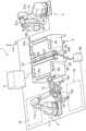
回転ツールは、摩擦攪拌接合に用いられるツールである。図1に示すように、回転ツールFは、例えば工具鋼で形成されており、基軸部F1と、基端側ピンF2と、先端側ピンF3とで主に構成されている。基軸部F1は、円柱状を呈し、摩擦攪拌装置の主軸に接続される部位である。
[A. Rotate tool]
A rotary tool is a tool used for friction stir welding. As shown in FIG. 1, the rotary tool F is made of tool steel, for example, and mainly includes a base shaft portion F1, a proximal pin F2, and a distal pin F3. The base shaft portion F1 has a cylindrical shape and is a portion connected to the main shaft of the friction stirrer.

基端側ピンF2は、基軸部F1に連続し、先端に向けて先細りになっている。基端側ピンF2は、円錐台形状を呈する。基端側ピンF2のテーパー角度Aは適宜設定すればよいが、例えば、135~160°になっている。テーパー角度Aが135°未満であるか、又は、160°を超えると摩擦攪拌後の接合表面粗さが大きくなる。テーパー角度Aは、後記する先端側ピンF3のテーパー角度Bよりも大きくなっている。図2に示すように、基端側ピンF2の外周面には、階段状のピン段差部F21が高さ方向の全体に亘って形成されている。ピン段差部F21は、右回り又は左回りで螺旋状に形成されている。つまり、ピン段差部F21は、平面視して螺旋状であり、側面視すると階段状になっている。本実施形態では、回転ツールFを右回転させるため、ピン段差部F21は基端側から先端側に向けて左回りに設定している。 The proximal pin F2 is continuous with the base shaft portion F1 and tapers toward the distal end. The proximal pin F2 has a truncated cone shape. The taper angle A of the proximal pin F2 may be set as appropriate, and is, for example, 135 to 160°. When the taper angle A is less than 135° or more than 160°, the bonded surface roughness after friction stirring becomes large. The taper angle A is larger than the taper angle B of the tip end pin F3, which will be described later. As shown in FIG. 2, a step-like pin stepped portion F21 is formed on the outer peripheral surface of the proximal pin F2 over the entire height direction. The pin step portion F21 is spirally formed clockwise or counterclockwise. That is, the pin stepped portion F21 has a spiral shape when viewed from above, and has a stepped shape when viewed from the side. In this embodiment, in order to rotate the rotary tool F clockwise, the pin stepped portion F21 is set counterclockwise from the base end side to the distal end side.

なお、回転ツールFを左回転させる場合は、ピン段差部F21を基端側から先端側に向けて右回りに設定することが好ましい。これにより、ピン段差部F21によって塑性流動材が先端側に導かれるため、被接合金属部材の外部に溢れ出る金属を低減することができる。ピン段差部F21は、段差底面F21aと、段差側面F21bとで構成されている。隣り合うピン段差部F21の各頂点F21c,F21cの距離X1(水平方向距離)は、後記する段差角度C及び段差側面F21bの高さY1に応じて適宜設定される。 In addition, when rotating the rotary tool F to the left, it is preferable to set the pin step part F21 clockwise from the base end side to the distal end side. As a result, the plastic flow material is guided to the tip side by the pin stepped portion F21, so it is possible to reduce metal overflowing to the outside of the metal members to be welded. The pin step portion F21 includes a step bottom surface F21a and a step side surface F21b. The distance X1 (horizontal distance) between the vertices F21c and F21c of the adjacent pin step portions F21 is appropriately set according to the step angle C and the height Y1 of the step side surface F21b, which will be described later.

段差側面F21bの高さY1は適宜設定すればよいが、例えば、0.1~0.4mmで設定されている。高さY1が0.1mm未満であると接合表面粗さが大きくなる。一方、高さY1が0.4mmを超えると接合表面粗さが大きくなる傾向があるとともに、有効段差部数(被接合金属部材と接触しているピン段差部F21の数)も減少する。 The height Y1 of the stepped side surface F21b may be set as appropriate, and is set to, for example, 0.1 to 0.4 mm. When the height Y1 is less than 0.1 mm, the bonding surface roughness becomes large. On the other hand, if the height Y1 exceeds 0.4 mm, the bonding surface roughness tends to increase, and the number of effective step portions (the number of pin step portions F21 in contact with the metal member to be welded) also decreases.

段差底面F21aと段差側面F21bとでなす段差角度Cは適宜設定すればよいが、例えば、85~120°で設定されている。段差底面F21aは、本実施形態では水平面と平行になっている。段差底面F21aは、ツールの回転軸から外周方向に向かって水平面に対して-5°~15°内の範囲で傾斜していてもよい(マイナスは水平面に対して下方、プラスは水平面に対して上方)。距離X1、段差側面F21bの高さY1、段差角度C及び水平面に対する段差底面F21aの角度は、摩擦攪拌を行う際に、塑性流動材がピン段差部F21の内部に滞留して付着することなく外部に抜けるとともに、段差底面F21aで塑性流動材を押えて接合表面粗さを小さくすることができるように適宜設定する。 The step angle C formed between the step bottom surface F21a and the step side surface F21b may be set as appropriate, but is set to 85 to 120 degrees, for example. In this embodiment, the step bottom surface F21a is parallel to the horizontal plane. The step bottom surface F21a may be inclined within a range of -5° to 15° with respect to the horizontal plane from the rotation axis of the tool toward the outer circumference (minus indicates downward with respect to the horizontal plane, positive indicates downward with respect to the horizontal plane). above). The distance X1, the height Y1 of the step side surface F21b, the step angle C, and the angle of the step bottom surface F21a with respect to the horizontal plane are such that when friction stirring is performed, the plastic fluid material does not stay inside the pin step portion F21 and adhere to the outside. It is appropriately set so that the joint surface roughness can be reduced by pressing the plastic flow material at the bottom surface F21a of the step.

図1に示すように、先端側ピンF3は、基端側ピンF2に連続して形成されている。先端側ピンF3は円錐台形状を呈する。先端側ピンF3の先端は回転軸に対して垂直な平坦面F4になっている。先端側ピンF3のテーパー角度Bは、基端側ピンF2のテーパー角度Aよりも小さくなっている。図2に示すように、先端側ピンF3の外周面には、螺旋溝F31が刻設されている。螺旋溝F31は、右回り、左回りのどちらでもよいが、本実施形態では回転ツールFを右回転させるため、基端側から先端側に向けて左回りに刻設されている。 As shown in FIG. 1, the distal pin F3 is formed continuously from the proximal pin F2. The tip side pin F3 has a truncated cone shape. The tip of the tip side pin F3 is a flat surface F4 perpendicular to the rotation axis. The taper angle B of the distal pin F3 is smaller than the taper angle A of the proximal pin F2. As shown in FIG. 2, a spiral groove F31 is carved on the outer circumferential surface of the tip end pin F3. The spiral groove F31 may be clockwise or counterclockwise, but in this embodiment, in order to rotate the rotary tool F clockwise, it is carved counterclockwise from the base end toward the distal end.

なお、回転ツールFを左回転させる場合は、螺旋溝F31を基端側から先端側に向けて右回りに設定することが好ましい。これにより、螺旋溝F31によって塑性流動材が先端側に導かれるため、被接合金属部材の外部に溢れ出る金属を低減することができる。螺旋溝F31は、螺旋底面F31aと、螺旋側面F31bとで構成されている。隣り合う螺旋溝F31の頂点F31c,F31cの距離(水平方向距離)を長さX2とする。螺旋側面F31bの高さを高さY2とする。螺旋底面F31aと、螺旋側面F31bとで構成される螺旋角度DAは例えば、45~90°で形成されている。螺旋溝F31は、被接合金属部材と接触することにより摩擦熱を上昇させるとともに、塑性流動材を先端側に導く役割を備えている。 In addition, when rotating the rotary tool F counterclockwise, it is preferable to set the spiral groove F31 clockwise from the base end side to the distal end side. As a result, the plastic flow material is guided to the tip side by the spiral groove F31, so it is possible to reduce metal overflowing to the outside of the metal members to be welded. The spiral groove F31 includes a spiral bottom surface F31a and a spiral side surface F31b. The distance (horizontal distance) between the vertices F31c and F31c of adjacent spiral grooves F31 is defined as length X2. The height of the spiral side surface F31b is defined as a height Y2. The spiral angle DA formed by the spiral bottom surface F31a and the spiral side surface F31b is, for example, 45 to 90 degrees. The spiral groove F31 has the role of increasing frictional heat by contacting the metal member to be welded and guiding the plastic fluid material to the tip side.

回転ツールFは、適宜設計変更が可能である。図3は、本発明の回転ツールの第一変形例を示す側面図である。図3に示すように、第一変形例に係る回転ツールFAでは、ピン段差部F21の段差底面F21aと段差側面F21bとのなす段差角度Cが85°になっている。段差底面F21aは、水平面と平行である。このように、段差底面F21aは水平面と平行であるとともに、段差角度Cは、摩擦攪拌中にピン段差部F21内に塑性流動材が滞留して付着することなく外部に抜ける範囲で鋭角としてもよい。 The design of the rotary tool F can be changed as appropriate. FIG. 3 is a side view showing a first modification of the rotary tool of the present invention. As shown in FIG. 3, in the rotary tool FA according to the first modification, the step angle C between the step bottom surface F21a and the step side surface F21b of the pin step portion F21 is 85 degrees. The step bottom surface F21a is parallel to the horizontal surface. In this way, the step bottom surface F21a is parallel to the horizontal plane, and the step angle C may be an acute angle within a range where the plastic fluid material stays in the pin step portion F21 during friction stirring and escapes to the outside without sticking. .

図4は、本発明の回転ツールの第二変形例を示す側面図である。図4に示すように、第二変形例に係る回転ツールFBでは、ピン段差部F21の段差角度Cが115°になっている。段差底面F21aは水平面と平行になっている。このように、段差底面F21aは水平面と平行であるとともに、ピン段差部F21として機能する範囲で段差角度Cが鈍角となってもよい。 FIG. 4 is a side view showing a second modification of the rotary tool of the present invention. As shown in FIG. 4, in the rotary tool FB according to the second modification, the step angle C of the pin step portion F21 is 115°. The step bottom surface F21a is parallel to the horizontal surface. In this way, the step bottom surface F21a may be parallel to the horizontal plane, and the step angle C may be an obtuse angle within the range that functions as the pin step portion F21.

図5は、本発明の回転ツールの第三変形例を示す側面図である。図5に示すように、第三変形例に係る回転ツールFCでは、段差底面F21aがツールの回転軸から外周方向に向かって水平面に対して10°上方に傾斜している。段差側面F21bは、鉛直面と平行になっている。このように、摩擦攪拌中に塑性流動材を押さえることができる範囲で、段差底面F21aがツールの回転軸から外周方向に向かって水平面よりも上方に傾斜するように形成されていてもよい。 FIG. 5 is a side view showing a third modification of the rotary tool of the present invention. As shown in FIG. 5, in the rotary tool FC according to the third modification, the step bottom surface F21a is inclined upward by 10 degrees with respect to the horizontal plane toward the outer circumferential direction from the rotation axis of the tool. The stepped side surface F21b is parallel to the vertical plane. In this way, the step bottom surface F21a may be formed to be inclined upward from the horizontal plane toward the outer circumferential direction from the rotation axis of the tool within a range that can suppress the plastic flow material during friction stirring.

[B.第一実施形態]
[B-1.自動接合システム]
次に、図6に示すように、本発明の第一実施形態に係る自動接合システム1について説明する。なお、以下の説明では「裏面」の反対側の面を「表面」とする。
[B. First embodiment]
[B-1. Automatic joining system]
Next, as shown in FIG. 6, an automatic joiningsystem 1 according to a first embodiment of the present invention will be described. In the following description, the surface opposite to the "back surface" will be referred to as the "front surface."

図6及び図7に示すように、自動接合システム1は、搬送装置2と、固定装置3と、摩擦攪拌装置4と、制御装置5とを含んで構成されている。自動接合システム1は、第一金属部材101と第二金属部材102の端部同士を自動で摩擦攪拌接合するシステムである。 As shown in FIGS. 6 and 7, the automatic joiningsystem 1 includes a conveyingdevice 2, a fixingdevice 3, afriction stir device 4, and acontrol device 5. The automatic joiningsystem 1 is a system that automatically friction stir welds the ends of afirst metal member 101 and asecond metal member 102.

図7に示すように、第一金属部材101及び第二金属部材102は、アルミニウム、アルミニウム合金、チタン、チタン合金、マグネシウム、マグネシウム合金、銅、銅合金等の摩擦攪拌可能な金属で形成された板状部材である。第二金属部材102の板厚寸法は、第一金属部材101の板厚寸法よりも小さくなっている。第一金属部材101及び第二金属部材102は、本実施形態では、例えば、アルミニウム合金で形成されている。 As shown in FIG. 7, thefirst metal member 101 and thesecond metal member 102 are made of a friction stirable metal such as aluminum, aluminum alloy, titanium, titanium alloy, magnesium, magnesium alloy, copper, copper alloy, etc. It is a plate-like member. The plate thickness dimension of thesecond metal member 102 is smaller than the plate thickness dimension of thefirst metal member 101. In this embodiment, thefirst metal member 101 and thesecond metal member 102 are made of, for example, an aluminum alloy.

図7に示すように、第一金属部材101の端面101aと、第二金属部材102の端面102aとが突き合わされて突合せ部J1が形成されている。第一金属部材101の裏面101c及び第二金属部材102の裏面102c同士は面一となっているため、表面101b,102bには段差が形成されている。すなわち、第一金属部材101の表面101bよりも第二金属部材102の表面102bの高さ位置が低くなるように、端面101a,102a同士が突き合わされている。 As shown in FIG. 7, theend surface 101a of thefirst metal member 101 and theend surface 102a of thesecond metal member 102 are butted against each other to form a butt portion J1. Since theback surface 101c of thefirst metal member 101 and theback surface 102c of thesecond metal member 102 are flush with each other, a step is formed between thesurfaces 101b and 102b. That is, theend surfaces 101a and 102a are butted against each other such that thesurface 102b of thesecond metal member 102 is lower in height than thesurface 101b of thefirst metal member 101.

なお、第一金属部材101及び第二金属部材102は、摩擦攪拌接合工程ごとに順次搬送され、接合後に固定装置3の外部へ取り出されるが、各第一金属部材101及び第二金属部材102を識別するために、接合の順番で通し番号(以下、「ワーク番号」という。)を付すものとする。また、本実施形態では、第一金属部材101及び第二金属部材102の板厚寸法が異なっているが、第一金属部材101及び第二金属部材102の板厚寸法を同一にして表面101b,102bの高さ位置に差を設けて突き合わせてもよい。 Note that thefirst metal member 101 and thesecond metal member 102 are sequentially conveyed in each friction stir welding process, and are taken out of the fixingdevice 3 after welding. For identification, serial numbers (hereinafter referred to as "work numbers") shall be given in the order of joining. Further, in this embodiment, although thefirst metal member 101 and thesecond metal member 102 have different plate thicknesses, thefirst metal member 101 and thesecond metal member 102 have the same plate thickness, and thesurface 101b, 102b may be butted against each other with a difference in height.

[B-1-1.搬送装置]
搬送装置2は、図6及び図8に示すように、アームロボット11と、基部フレーム12と、4つの吸着部13とを含んで構成されている。アームロボット11は、制御装置5と電気的に接続されている。制御装置5の搬送制御部51(図8参照)は、アームロボット11の搬送動作を制御する装置である。アームロボット11は、多関節のアーム11a及びアーム駆動部(図示省略)を備えており、搬送制御部51から送信される制御信号に基づいて立体的な動作が可能となっている。
[B-1-1. Conveyance device]
As shown in FIGS. 6 and 8, thetransfer device 2 includes anarm robot 11, abase frame 12, and foursuction sections 13. Thearm robot 11 is electrically connected to thecontrol device 5. The transport control unit 51 (see FIG. 8) of thecontrol device 5 is a device that controls the transport operation of thearm robot 11. Thearm robot 11 includes amulti-jointed arm 11a and an arm drive section (not shown), and is capable of three-dimensional movement based on a control signal transmitted from thetransfer control section 51.

基部フレーム12は、アームロボット11のアームの先端に取り付けられた枠状部材である。基部フレーム12は、アーム11aの軸方向に対して垂直に取り付けられている。吸着部13は、基部フレーム12の四隅に、基部フレーム12の平面に対して垂直に設けられている。吸着部13は、搬送制御部51の制御信号に基づいて、先端に設けられた吸着パッド13aに負圧又は正圧を作用させることができる。つまり、吸着パッド13aに負圧を作用させることで、第一金属部材101又は第二金属部材102の四隅を吸着することでき、正圧を作用させることにより第一金属部材101又は第二金属部材102を離脱させることができる。これにより、アームロボット11は、第一金属部材101及び第二金属部材102を固定装置3の予め設定された位置にそれぞれ搬送することができる。例えば、接合前の第一金属部材101及び第二金属部材102は、搬送装置2による第一金属部材101及び第二金属部材102の吸着が可能な範囲内の位置にある材料配置エリア(図示省略)にそれぞれ積層して配置しておくことができる。搬送装置2は、材料配置エリアに配置された第一金属部材101及び第二金属部材102を、それぞれ一部材ずつ架台21の所定位置まで搬送することができる。 Thebase frame 12 is a frame-shaped member attached to the tip of the arm of thearm robot 11. Thebase frame 12 is attached perpendicularly to the axial direction of thearm 11a. Thesuction parts 13 are provided at the four corners of thebase frame 12 perpendicularly to the plane of thebase frame 12. Thesuction unit 13 can apply negative pressure or positive pressure to thesuction pad 13a provided at the tip based on a control signal from thetransport control unit 51. That is, by applying negative pressure to thesuction pad 13a, the four corners of thefirst metal member 101 or thesecond metal member 102 can be suctioned, and by applying positive pressure to thefirst metal member 101 or thesecond metal member 102 can be removed. Thereby, thearm robot 11 can transport thefirst metal member 101 and thesecond metal member 102 to preset positions of the fixingdevice 3, respectively. For example, thefirst metal member 101 and thesecond metal member 102 before joining are placed in a material placement area (not shown) located within a range where thefirst metal member 101 and thesecond metal member 102 can be adsorbed by the conveyance device 2. ) can be stacked and arranged. Thetransport device 2 can transport thefirst metal member 101 and thesecond metal member 102 placed in the material placement area one by one to a predetermined position on thepedestal 21 .

また、アームロボット11は、摩擦攪拌接合後に、接合された第一金属部材101及び第二金属部材102(以下、「被接合金属部材103」とも言う。)を固定装置3から取り出して、所定の位置に搬送することができる。アームロボット11は、例えば、制御装置5に合格品と判定された場合は被接合金属部材103を合格品配置エリア15(図6参照)に搬送し、数値範囲外品と判定された場合は被接合金属部材103を数値範囲外品配置エリア16に搬送することができる。なお、数値範囲外品とは、制御装置5で所定の数値範囲内ではない(数値範囲外)と判定された被接合金属部材103を言う。 Further, after friction stir welding, thearm robot 11 takes out the weldedfirst metal member 101 and second metal member 102 (hereinafter also referred to as "metal members 103 to be welded") from the fixingdevice 3 and places them in a predetermined position. can be transported to the desired location. For example, thearm robot 11 transports the metal member 103 to be welded to the acceptable product placement area 15 (see FIG. 6) when thecontrol device 5 determines that the product is an acceptable product, and transports the metal member 103 to be welded when the product is determined to be outside the numerical range. The bonded metal member 103 can be transported to the out-of-value rangeproduct placement area 16. Note that a product outside the numerical value range refers to a metal member 103 to be welded that is determined by thecontrol device 5 to be not within a predetermined numerical value range (outside the numerical value range).

[B-1-2.固定装置]
固定装置3は、第一金属部材101及び第二金属部材102を固定するとともに、摩擦攪拌接合の台座となる装置である。図6及び図8に示すように、固定装置3は、架台21と、吸引部22と、温度調整部23と、クランプ部24とを含んで構成されている。
[B-1-2. Fixation device]
The fixingdevice 3 is a device that fixes thefirst metal member 101 and thesecond metal member 102 and serves as a pedestal for friction stir welding. As shown in FIGS. 6 and 8, the fixingdevice 3 includes apedestal 21, asuction section 22, atemperature adjustment section 23, and aclamp section 24.

<架台>
架台21は、上部の表面に第一金属部材101及び第二金属部材102が配置される台であって、外形が直方体を呈する。架台21の上部表面における中央位置には、架台21の長手方向の稜線21aに対して垂直な基準位置Y0が設定されている。基準位置Y0は、第一金属部材101及び第二金属部材102の位置決めの基準となる位置である。第一金属部材101及び第二金属部材102は、基準位置Y0の位置において突合せ部J1を形成するように配置される。ここで、以下の説明におけるX方向、Y方向、Z方向は図6,図7に示す矢印に基づく。図6,図7に示すように、X方向、Y方向、Z方向は互いに直交している。X方向は、架台21の上部平面において、基準位置Y0に対して平行となっている。Y方向は、架台21の上部平面において、基準位置Y0に対して垂直となっている。Z方向は、架台21の上部平面に対して垂直となっている。
<Frame>
Thepedestal 21 is a pedestal on which thefirst metal member 101 and thesecond metal member 102 are arranged on the upper surface, and has a rectangular parallelepiped outer shape. A reference position Y0 perpendicular to thelongitudinal ridgeline 21a of thepedestal 21 is set at the center position on the upper surface of thepedestal 21. The reference position Y0 is a position that serves as a reference for positioning thefirst metal member 101 and thesecond metal member 102. Thefirst metal member 101 and thesecond metal member 102 are arranged so as to form an abutting portion J1 at the reference position Y0. Here, the X direction, Y direction, and Z direction in the following description are based on the arrows shown in FIGS. 6 and 7. As shown in FIGS. 6 and 7, the X direction, Y direction, and Z direction are orthogonal to each other. The X direction is parallel to the reference position Y0 on the upper plane of thepedestal 21. The Y direction is perpendicular to the reference position Y0 on the upper plane of thepedestal 21. The Z direction is perpendicular to the upper plane of thepedestal 21.

架台21の表面側の中央部には、基準位置Y0に沿って凹溝25aが形成されている。凹溝25a内には、基準位置Y0に沿って、突合せ部J1に対応する位置に載置部25が設けられている。載置部25は、本実施形態では架台21のX方向の長さと概ね同じ長さからなり、第一金属部材101と第二金属部材102との摩擦撹拌接合によって形成される塑性流動領域の幅と同程度かこれよりも大きい幅に形成されている。また、載置部25は、アルミニウム又はアルミニウム合金板で形成されている。載置部25の表面側には陽極酸化被膜が施されている。載置部25は、架台21の表面に配置されて、その上に載置された第一金属部材101及び第二金属部材102を支持するとともに、第一金属部材101及び第二金属部材102の温度調整を行うためのバッキングプレートとして機能する。 Agroove 25a is formed in the center of the front surface of thepedestal 21 along the reference position Y0. A mountingportion 25 is provided in thegroove 25a at a position corresponding to the butt portion J1 along the reference position Y0. In this embodiment, the mountingportion 25 has a length that is approximately the same as the length of thepedestal 21 in the X direction, and has a width equal to the width of the plastic flow region formed by friction stir welding between thefirst metal member 101 and thesecond metal member 102. The width is the same as or larger than that. Moreover, the mountingportion 25 is formed of an aluminum or aluminum alloy plate. An anodic oxide film is applied to the surface side of the mountingportion 25. The mountingsection 25 is arranged on the surface of thepedestal 21 and supports thefirst metal member 101 and thesecond metal member 102 placed thereon, and also supports thefirst metal member 101 and thesecond metal member 102. Functions as a backing plate for temperature adjustment.

<吸引部>
吸引部22は、第二金属部材102の端部を裏面102c側から吸引する装置である。吸引部22は、吸引管26と、ホース28と、吸引機29とを含んで構成されている。吸引管26は、断面矩形の中空管である。図7に示すように、吸引管26は、架台21の表面側においてX方向と平行に設けられた凹溝25a内に設置されている。凹溝25a内において、第一金属部材101側に配置される載置部25と、第二金属部材102側に配置される吸引管26とが、長手方向で隣接して設置されている。吸引管26の表面と、載置部25の表面は面一になっている。本実施形態では、例えば、吸引管26の表面長手方向の第一金属部材101側の稜線26aは、基準位置Y0に対して第二金属部材102の側に位置するように設定されている。
<Suction part>
Thesuction unit 22 is a device that suctions the end of thesecond metal member 102 from theback surface 102c side. Thesuction section 22 includes asuction tube 26, ahose 28, and asuction device 29. Thesuction tube 26 is a hollow tube with a rectangular cross section. As shown in FIG. 7, thesuction tube 26 is installed in agroove 25a provided on the surface side of thepedestal 21 in parallel to the X direction. In thegroove 25a, the mountingportion 25 disposed on thefirst metal member 101 side and thesuction pipe 26 disposed on thesecond metal member 102 side are installed adjacent to each other in the longitudinal direction. The surface of thesuction tube 26 and the surface of the mountingportion 25 are flush with each other. In this embodiment, for example, theridge line 26a on thefirst metal member 101 side in the surface longitudinal direction of thesuction tube 26 is set to be located on thesecond metal member 102 side with respect to the reference position Y0.

吸引管26の表面には、所定の間隔で複数の孔部27が開口している。吸引管26は、ホース28を介して吸引機29に連結されている。吸引機29は、吸引して負圧を発生させる機械であり、制御装置5の吸引制御部52(図8参照)と電気的に接続されている。制御装置5の吸引制御部52は、吸引機29の吸引動作を制御する。つまり、吸引機29は、吸引制御部52から送信される制御信号に基づいて吸引ON又は吸引OFFとすることができる。吸引部22は、孔部27周りに負圧を発生させることにより、第二金属部材102の端部を吸引して、当該端部の浮き上がりを防ぐことができる。 A plurality ofholes 27 are opened on the surface of thesuction tube 26 at predetermined intervals. Thesuction pipe 26 is connected to asuction machine 29 via ahose 28. Thesuction machine 29 is a machine that generates negative pressure by suction, and is electrically connected to the suction control section 52 (see FIG. 8) of thecontrol device 5. Thesuction control unit 52 of thecontrol device 5 controls the suction operation of thesuction machine 29. In other words, thesuction device 29 can be turned on or off based on the control signal sent from thesuction control unit 52. By generating negative pressure around thehole 27, thesuction section 22 can suck the end of thesecond metal member 102 and prevent the end from rising.

なお、本実施形態では、第二金属部材102を吸引するようにしたが、第一金属部材101及び第二金属部材102の両方を吸引するようにしてもよい。吸引管26は複数本設けてもよい。 In this embodiment, thesecond metal member 102 is sucked, but both thefirst metal member 101 and thesecond metal member 102 may be sucked. A plurality ofsuction tubes 26 may be provided.

<温度調整部>
温度調整部23は、図6及び図8に示すように、固定装置3の架台21の内部に設けられ、架台21の温度の測定、及び架台21表面の温度調整を行う装置である。温度調整部23は、ヒーター(図示省略)、及び温度センサ23a(図8参照)を含んで構成されている。架台21の表面側から、載置部25と、温度センサ23aと、ヒーターとが、この順で設けられている。ヒーターは、基準位置Y0に沿って、載置部25と概ね同じ位置に対応するように配置されている。温度センサ23aは載置部25の温度を測定し、ヒーターは載置部25の温度を調整する。温度調整部23は、制御装置5の温度制御部53と電気的に接続されている。温度調整部23は、温度制御部53から送信される制御信号に基づいて、ヒーターの動作を制御可能に構成されている。例えば、ヒーターを作動させることで載置部25を加温し、又はヒーターを停止させることで載置部25を室温付近まで冷却することができるように構成されている。このようにして、温度調整部23は、温度センサ23aによって架台21表面の載置部25の温度を測定し、ヒーターによって架台21表面の載置部25の温度を調整することができる。そして、載置部25の温度を調整することで、第一金属部材101及び第二金属部材102の温度を上昇又は下降させることができる。なお、温度調整部23は、さらに冷却装置を備え、この冷却装置を作動させることで載置部25を冷却するようにしてもよい。
<Temperature adjustment section>
As shown in FIGS. 6 and 8, thetemperature adjustment unit 23 is provided inside thepedestal 21 of the fixingdevice 3, and is a device that measures the temperature of thepedestal 21 and adjusts the temperature of the surface of thepedestal 21. Thetemperature adjustment section 23 includes a heater (not shown) and atemperature sensor 23a (see FIG. 8). A mountingsection 25, atemperature sensor 23a, and a heater are provided in this order from the front side of thepedestal 21. The heater is arranged so as to correspond to approximately the same position as the mountingportion 25 along the reference position Y0. Thetemperature sensor 23a measures the temperature of the mountingsection 25, and the heater adjusts the temperature of the mountingsection 25. Thetemperature adjustment section 23 is electrically connected to thetemperature control section 53 of thecontrol device 5. Thetemperature adjustment section 23 is configured to be able to control the operation of the heater based on a control signal transmitted from thetemperature control section 53. For example, the configuration is such that the mountingsection 25 can be heated by operating a heater, or the mountingsection 25 can be cooled to around room temperature by stopping the heater. In this way, thetemperature adjustment section 23 can measure the temperature of the mountingsection 25 on the surface of thepedestal 21 using thetemperature sensor 23a, and adjust the temperature of the mountingsection 25 on the surface of thepedestal 21 using the heater. By adjusting the temperature of the mountingportion 25, the temperatures of thefirst metal member 101 and thesecond metal member 102 can be increased or decreased. Note that thetemperature adjustment section 23 may further include a cooling device, and the mountingsection 25 may be cooled by operating this cooling device.

各摩擦攪拌接合を行う前において、温度調整部23の温度センサ23aで計測された結果は、ワーク番号と関連付けられて制御装置5の温度制御部53に送信されるとともに、記憶部44に格納される。温度センサ23aで計測された結果は、ワーク番号とともに制御装置5の表示部43に表示されるようにしてもよい。 Before performing each friction stir welding, the results measured by thetemperature sensor 23a of thetemperature adjustment section 23 are transmitted to thetemperature control section 53 of thecontrol device 5 in association with the workpiece number, and are also stored in thestorage section 44. Ru. The result measured by thetemperature sensor 23a may be displayed on thedisplay section 43 of thecontrol device 5 together with the work number.

<クランプ部>
クランプ部24は、図7及び図8に示すように、架台21の周囲に移動可能に配置され、架台21に対して第一金属部材101及び第二金属部材102を固定又は解除する装置である。クランプ部24は、制御装置5のクランプ制御部54(図8参照)から送信される制御信号に基づいて、第一金属部材101及び第二金属部材102の固定又は解除を行う。つまり、クランプ部24は、架台21に第一金属部材101及び第二金属部材102が配置された後、第一金属部材101及び第二金属部材102に近接しつつ、第一金属部材101及び第二金属部材102を架台21に移動不能に拘束する。一方、クランプ部24は、摩擦攪拌接合が終了したら拘束を解除して、被接合金属部材103を取り出す際に干渉しない位置まで退避する。
<Clamp part>
As shown in FIGS. 7 and 8, theclamp section 24 is a device that is movably arranged around thepedestal 21 and fixes or releases thefirst metal member 101 and thesecond metal member 102 with respect to thepedestal 21. . Theclamp unit 24 fixes or releases thefirst metal member 101 and thesecond metal member 102 based on a control signal transmitted from the clamp control unit 54 (see FIG. 8) of thecontrol device 5. That is, after thefirst metal member 101 and thesecond metal member 102 are placed on thepedestal 21, theclamp part 24 approaches thefirst metal member 101 and thesecond metal member 102, and The twometal members 102 are immovably restrained on thepedestal 21. On the other hand, when the friction stir welding is completed, theclamp part 24 releases its restraint and retreats to a position where it does not interfere when the metal member 103 to be welded is taken out.

[B-1-3.摩擦攪拌装置]
摩擦攪拌装置4は、図6及び図8に示すように、アームロボット31と、回転駆動部32と、荷重付与部33と、測定部34と、荷重測定部35とを含んで構成されている。摩擦攪拌装置4は、回転ツールFを回転させつつ移動させて第一金属部材101と第二金属部材102とを摩擦攪拌接合する装置である。
[B-1-3. Friction stirrer]
As shown in FIGS. 6 and 8, thefriction stirrer 4 includes anarm robot 31, arotation drive section 32, aload application section 33, ameasurement section 34, and aload measurement section 35. . Thefriction stir device 4 is a device that performs friction stir welding of thefirst metal member 101 and thesecond metal member 102 by rotating and moving the rotary tool F.

アームロボット31は、制御装置5と電気的に接続されている。制御装置5の摩擦攪拌制御部55(図8参照)は、アームロボット31の摩擦攪拌接合動作を制御する装置である。アームロボット31は、多関節のアーム31a及びアーム駆動部(図示省略)を備えており、摩擦攪拌制御部55から送信される制御信号に基づいて立体的な動作が可能となっている。 Thearm robot 31 is electrically connected to thecontrol device 5. The friction stir control unit 55 (see FIG. 8) of thecontrol device 5 is a device that controls the friction stir welding operation of thearm robot 31. Thearm robot 31 includes amulti-joint arm 31a and an arm drive section (not shown), and is capable of three-dimensional movement based on a control signal transmitted from the frictionstir control section 55.

回転駆動部32は、回転ツールFを回転させるモータ等の回転駆動手段を含んで構成されている。回転駆動部32、荷重付与部33及び荷重測定部35は、筐体39(図6参照)内に収容されている。回転駆動部32の先端には、回転ツールFを着脱可能なチャック部が設けられている。摩擦攪拌制御部55(図8参照)は、回転ツールFが所定の回転数となるように回転駆動部32を制御する。 Therotation drive section 32 is configured to include rotation drive means such as a motor that rotates the rotary tool F. Therotation drive unit 32, theload application unit 33, and theload measurement unit 35 are housed in a housing 39 (see FIG. 6). A chuck part to which the rotary tool F can be attached and detached is provided at the tip of therotary drive part 32. The friction stir control section 55 (see FIG. 8) controls therotation drive section 32 so that the rotation tool F has a predetermined rotation speed.

荷重付与部33(図8参照)は、回転ツールFの軸方向に移動可能なシリンダ機構等を含んで構成されており、摩擦攪拌接合中において、第一金属部材101及び第二金属部材102に対する回転ツールFの押圧力を調整する部位である。 The load applying unit 33 (see FIG. 8) is configured to include a cylinder mechanism that is movable in the axial direction of the rotary tool F, and is configured to apply pressure to thefirst metal member 101 and thesecond metal member 102 during friction stir welding. This is a part that adjusts the pressing force of the rotary tool F.

荷重測定部35は、回転ツールFとモータ等の回転駆動手段との間に介設されており、摩擦攪拌接合中に回転ツールFが受ける軸方向の反力荷重を測定する装置である。荷重測定部35で計測された結果は、ワーク番号と関連付けられて制御装置5の摩擦攪拌制御部55に送信されるとともに、記憶部44に格納される。 Theload measuring section 35 is a device that is interposed between the rotary tool F and a rotation drive means such as a motor, and measures the axial reaction force load that the rotary tool F receives during friction stir welding. The results measured by theload measurement section 35 are transmitted to the frictionstir control section 55 of thecontrol device 5 in association with the workpiece number, and are also stored in thestorage section 44 .

荷重測定部35で計測された結果は、ワーク番号とともに制御装置5の表示部43に表示されるようにしてもよい。摩擦攪拌制御部55は、回転ツールFの反力荷重が、予め設定された設定荷重に近づくように荷重付与部33をフィードバック制御する。 The results measured by theload measuring section 35 may be displayed on thedisplay section 43 of thecontrol device 5 together with the workpiece number. The frictionstir control unit 55 performs feedback control on theload applying unit 33 so that the reaction load of the rotary tool F approaches a preset set load.

回転ツールFの押圧力(設定荷重)は、本実施形態では、例えば、2000~8000Nに設定されている。回転ツールFの押圧力は、通常、2000N以上、好ましくは2500N以上、より好ましくは3000Nである。また、回転ツールFの押圧力は、通常8000N以下、好ましくは6000N以下、より好ましくは4000N以下、特に好ましくは3500N以下である。 In this embodiment, the pressing force (set load) of the rotary tool F is set to, for example, 2000 to 8000N. The pressing force of the rotary tool F is usually 2000N or more, preferably 2500N or more, and more preferably 3000N. Further, the pressing force of the rotary tool F is usually 8000N or less, preferably 6000N or less, more preferably 4000N or less, particularly preferably 3500N or less.

<測定部>
測定部34は、回転駆動部32の外側に取り付けられた測定装置である。測定部34は、本実施形態ではラインセンサを用いている。測定部34は、照射されたラインレーザの反射光により、突合せ部J1(接合部)周りの凹凸、隙間、形状等を取得可能になっている。測定部34で計測された結果は、ワーク番号と関連付けられて制御装置5の摩擦攪拌制御部55に送信されるとともに、記憶部44に格納される。測定部34で計測された結果は、ワーク番号とともに制御装置5の表示部43に表示されるようにしてもよい。
<Measurement part>
The measuringunit 34 is a measuring device attached to the outside of therotation drive unit 32. Themeasurement unit 34 uses a line sensor in this embodiment. Themeasurement unit 34 is capable of acquiring irregularities, gaps, shapes, etc. around the abutting portion J1 (joint portion) using the reflected light of the irradiated line laser. The results measured by themeasurement unit 34 are transmitted to the frictionstir control unit 55 of thecontrol device 5 in association with the workpiece number, and are also stored in thestorage unit 44 . The results measured by themeasurement unit 34 may be displayed on thedisplay unit 43 of thecontrol device 5 together with the work number.

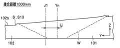
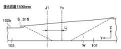
より詳しくは、測定部34は、摩擦攪拌接合を行う前にアームロボット31によって突合せ部J1に沿って移動することにより、突合せ部J1の段差寸法h、隙間量D及び第一金属部材101の稜線位置Ypを測定することができる。段差寸法hは、第一金属部材101の表面101bから第二金属部材102の表面102bまでの高さ寸法である。隙間量Dは、第一金属部材101の端面101aから第二金属部材102の端面102aまでの距離である。稜線位置Ypは、図7に示すように、第一金属部材101の突合せ部J1に面する上面側の稜線101eの形状(XY平面上の位置)である。 More specifically, before friction stir welding is performed, the measuringunit 34 moves along the abutting part J1 by thearm robot 31, thereby measuring the step dimension h of the abutting part J1, the gap amount D, and the ridge line of thefirst metal member 101. The position Yp can be measured. The step dimension h is the height dimension from thesurface 101b of thefirst metal member 101 to thesurface 102b of thesecond metal member 102. The gap amount D is the distance from theend surface 101a of thefirst metal member 101 to theend surface 102a of thesecond metal member 102. As shown in FIG. 7, the ridgeline position Yp is the shape (position on the XY plane) of theridgeline 101e on the upper surface side facing the abutting portion J1 of thefirst metal member 101.

また、測定部34は、摩擦攪拌接合中の回転ツールFの位置Yn(XY平面上の位置:図11参照)を測定することができる。また、測定部34は、摩擦攪拌接合前の回転ツールFの位置Yb(初期位置Yb0:図9参照)を測定することができる。この初期位置Yb0は、摩擦攪拌接合を行う際に、回転ツールFを第一金属部材101及び第二金属部材102に挿入する直前の回転ツールFの位置である。 Furthermore, the measuringunit 34 can measure the position Yn (position on the XY plane: see FIG. 11) of the rotary tool F during friction stir welding. Furthermore, the measuringunit 34 can measure the position Yb (initial position Yb0: see FIG. 9) of the rotary tool F before friction stir welding. This initial position Yb0 is the position of the rotary tool F immediately before it is inserted into thefirst metal member 101 and thesecond metal member 102 when performing friction stir welding.

また、測定部34は、摩擦攪拌接合後に突合せ部J1(接合部)に沿って移動することにより、接合部のバリ高さS(アンダーカット)及び表面粗さRaを測定することができる。つまり、測定部34は、摩擦攪拌接合後に接合部の状態、接合品質を確認するための検査部として機能することもできる。アンダーカットとは、第一金属部材101及び第二金属部材102の各表面101b,102bが接合前よりも凹んでいる(削れている)状態を言う。なお、本実施形態では、測定部34は、接合部のバリ高さS(アンダーカット)及び表面粗さRaの少なくとも一方を測定するようにしてもよい。また、測定部(検査部)34は、回転駆動部32を収容する筐体39の外側に取り付けたが、例えば、他のアームロボットに取り付けてもよい。また、測定部と検査部とは別の装置であってもよい。 Furthermore, themeasurement unit 34 can measure the burr height S (undercut) and surface roughness Ra of the joint by moving along the abutment J1 (joint) after friction stir welding. That is, themeasurement section 34 can also function as an inspection section for checking the state of the joint and the quality of the joint after friction stir welding. Undercut refers to a state in which thesurfaces 101b and 102b of thefirst metal member 101 and thesecond metal member 102 are depressed (shaved) more than before joining. In this embodiment, themeasurement unit 34 may measure at least one of the burr height S (undercut) and the surface roughness Ra of the joint. Further, although the measurement section (inspection section) 34 is attached to the outside of thecasing 39 that houses therotation drive section 32, it may be attached to another arm robot, for example. Further, the measurement section and the inspection section may be separate devices.

[B-1-4.制御装置]
制御装置5は、図8に示すように、搬送装置2、固定装置3及び摩擦攪拌装置4の全体の動作を制御する制御装置である。制御装置5は、演算部(CPU(Central ProcessingUnit):図示省略)と、キーボード、タッチパネル等の入力部42と、モニター、ディスプレイ等の表示部43と、RAM(Random Access Memory)、ROM(Read only memory)等の記憶部44とを含んで構成されている。
[B-1-4. Control device]
Thecontrol device 5 is a control device that controls the overall operation of the conveyingdevice 2, the fixingdevice 3, and thefriction stirring device 4, as shown in FIG. Thecontrol device 5 includes a calculation unit (CPU (Central Processing Unit): not shown), aninput unit 42 such as a keyboard or touch panel, adisplay unit 43 such as a monitor or display, a RAM (Random Access Memory), and a ROM (Read only). memory) and the like.

また、制御装置5は、主制御部41と、搬送制御部51と、吸引制御部52と、温度制御部53と、クランプ制御部54と、摩擦攪拌制御部55とを備えている。主制御部41は、搬送制御部51、吸引制御部52、温度制御部53、クランプ制御部54及び摩擦攪拌制御部55の各制御を統括する部位である。また、主制御部41は、一の摩擦攪拌接合が完了した後、記憶部44からそのワーク番号の判定結果を読み出して、当該第一金属部材101及び第二金属部材102(被接合金属部材103)が数値範囲外品と判定されたか否かを判定する判定部(図示省略)を備えている。 Thecontrol device 5 also includes amain control section 41 , aconveyance control section 51 , asuction control section 52 , atemperature control section 53 , aclamp control section 54 , and a friction stirringcontrol section 55 . Themain control section 41 is a section that centralizes control of theconveyance control section 51, thesuction control section 52, thetemperature control section 53, theclamp control section 54, and the friction stirringcontrol section 55. In addition, after one friction stir welding is completed, themain control unit 41 reads out the determination result of the workpiece number from thestorage unit 44, and reads out the determination result of the workpiece number from thestorage unit 44, and ) is determined to be a product outside the numerical range.

主制御部41、搬送制御部51、吸引制御部52、温度制御部53、クランプ制御部54、及び摩擦攪拌制御部55は、自動接合プログラムとしてROMに格納されている。演算部がROMから自動接合プログラムを読み込んで、RAMに展開して実行することで、主制御部41、搬送制御部51、吸引制御部52、温度制御部53、クランプ制御部54、及び摩擦攪拌制御部55の各部位として機能させる。自動接合プログラムは、CD-ROM(Compact Disc Read only memory)、DVD-ROM(Digital Versatile Disc Read only memory)等の光ディスク;USB(Universal Serial Bus)メモリ、SDメモリ等のフラッシュメモリ等の記録媒体に記録されて配布されてもよく、インターネット、イントラネット等の通信ネットワークを通じて配布されてもよい。制御装置5は、記録媒体から自動接合プログラムを読みだしたり、通信ネットワークを介して自動接合プログラムを受信したりすることで、自動接合プログラムを取得して実行することができる。 Themain control section 41, theconveyance control section 51, thesuction control section 52, thetemperature control section 53, theclamp control section 54, and the frictionstir control section 55 are stored in the ROM as an automatic welding program. The calculation section reads the automatic joining program from the ROM, expands it to the RAM, and executes it, thereby controlling themain control section 41, theconveyance control section 51, thesuction control section 52, thetemperature control section 53, theclamp control section 54, and the friction stirring section. It is made to function as each part of thecontrol section 55. The automatic joining program can be used to record media such as optical discs such as CD-ROM (Compact Disc Read only memory) and DVD-ROM (Digital Versatile Disc Read only memory); USB (Universal Serial Bus) memory, and flash memory such as SD memory. It may be recorded and distributed, or it may be distributed over a communications network such as the Internet, an intranet, or the like. Thecontrol device 5 can acquire and execute the automatic joining program by reading the automatic joining program from a recording medium or receiving the automatic joining program via a communication network.

なお、本実施形態では、各制御部を制御装置5内に一括して設けたが、装置ごとに制御部を設けてもよいし、制御装置5と各装置で制御部を共有してもよい。 Note that in this embodiment, each control unit is provided in thecontrol device 5 at once, but a control unit may be provided for each device, or thecontrol device 5 and each device may share the control unit. .

<搬送制御部>
搬送制御部51は、搬送装置2に制御信号を送信して第一金属部材101及び第二金属部材102を架台21の所定位置まで搬送する制御を行う。一方、搬送制御部51は、一の摩擦攪拌接合が終了しクランプ部24が退避したら、架台21から被接合金属部材103を取り出す制御を行う。
<Transport control unit>
Thetransport control unit 51 transmits a control signal to thetransport device 2 to control transporting thefirst metal member 101 and thesecond metal member 102 to a predetermined position on thepedestal 21 . On the other hand, theconveyance control unit 51 performs control to take out the metal member 103 to be welded from thepedestal 21 after one friction stir welding is completed and theclamp unit 24 is retracted.

また、搬送制御部51は、一度でも数値範囲外品との判定を受けたと主制御部41で判定された場合、架台21から当該被接合金属部材103を取り出して、数値範囲外品配置エリア16に搬送する制御を行う。一方、搬送制御部51は、主制御部41で数値範囲外品との判定を一度も受けていないと判定された場合、架台21から当該被接合金属部材103を取り出して、合格品配置エリア15に搬送する制御を行う。なお、数値範囲外品か否かの判定によらず、摩擦攪拌接合後に被接合金属部材103を同じ位置に搬送するように制御してもよい。 Furthermore, if themain control unit 41 determines that the product is outside the numerical range even once, theconveyance control unit 51 takes out the metal member 103 to be welded from thepedestal 21 and places it in the outside numericalrange placement area 16. Controls the conveyance to On the other hand, if themain control unit 41 determines that the product has never been determined to be a product outside the numerical range, thetransport control unit 51 takes out the metal member 103 to be welded from thepedestal 21 and places it in the acceptableproduct placement area 15. Controls the conveyance to Note that control may be performed so that the metal members 103 to be welded are transported to the same position after friction stir welding, regardless of whether the product is outside the numerical value range or not.

<吸引制御部>
吸引制御部52は、クランプ部24が第一金属部材101及び第二金属部材102を架台21に固定した後、吸引部22に制御信号を送信して吸引機29を吸引ONとし、架台21に固定された第二金属部材102の端部を吸引する制御を行う。吸引制御部52は、その摩擦攪拌接合が終了したら、吸引OFFとする制御を行う。
<Suction control section>
After theclamp unit 24 fixes thefirst metal member 101 and thesecond metal member 102 to thepedestal 21, thesuction control unit 52 transmits a control signal to thesuction unit 22 to turn thesuction device 29 on to suction. Control is performed to suck the end of the fixedsecond metal member 102. When the friction stir welding is completed, thesuction control unit 52 performs control to turn off the suction.

<温度制御部>
温度制御部53は、温度調整部23に制御信号を送信して設定された温度となるようにヒーターを作動又は停止させる制御を行う。温度調整部23の所定の数値範囲は、適宜設定すればよいが、例えば、30~120℃に設定し、好ましくは60~90℃に設定する。
<Temperature control section>
Thetemperature control unit 53 transmits a control signal to thetemperature adjustment unit 23 and controls the heater to operate or stop so as to reach a set temperature. The predetermined numerical range of thetemperature adjustment section 23 may be set as appropriate, but is set to, for example, 30 to 120°C, preferably 60 to 90°C.

また、温度制御部53は、判定部66を備えている。判定部66は、一の摩擦攪拌接合の直前において、温度制御部53の温度センサ23aから送信された結果(温度T)が所定の数値範囲内か否かを判定する。なお、温度Tは、架台21表面の温度、より具体的には載置部25の温度を表すものである。 Furthermore, thetemperature control section 53 includes adetermination section 66 . Immediately before one friction stir welding, thedetermination unit 66 determines whether the result (temperature T) transmitted from thetemperature sensor 23a of thetemperature control unit 53 is within a predetermined numerical range. Note that the temperature T represents the temperature of the surface of thepedestal 21, more specifically, the temperature of the mountingsection 25.

判定部66は、温度Tを所定の数値範囲外と判定した場合、その第一金属部材101及び第二金属部材102をワーク番号と関連付けて数値範囲外品と判定する。判定部66は、当該判定結果を主制御部41に送信するとともに記憶部44に格納する。当該判定結果は、表示部43に表示させるようにしてもよいし、判定結果に応じて音や光などを出力する報知手段で報知するようにしてもよい。また、判定部66は、主制御41に設けてもよい。 When thedetermination unit 66 determines that the temperature T is outside the predetermined numerical value range, thedetermination unit 66 associates thefirst metal member 101 and thesecond metal member 102 with the workpiece number and determines that thefirst metal member 101 and thesecond metal member 102 are products outside the numerical value range. Thedetermination unit 66 transmits the determination result to themain control unit 41 and stores it in thestorage unit 44 . The determination result may be displayed on thedisplay unit 43, or may be notified by a notification means that outputs sound, light, etc. according to the determination result. Further, thedetermination unit 66 may be provided in themain control 41.

なお、温度センサ23aから送信された結果が所定の数値範囲外と判定された場合、温度制御部53は、温度調整部23のヒーターの制御により載置部25を加温又は冷却させて、温度センサ23aから送信される結果が所定の数値範囲に含まれるように制御してもよい。 Note that when it is determined that the result transmitted from thetemperature sensor 23a is outside the predetermined numerical range, thetemperature control section 53 controls the heater of thetemperature adjustment section 23 to heat or cool the mountingsection 25 to adjust the temperature. You may control so that the result transmitted from thesensor 23a falls within a predetermined numerical range.

<クランプ制御部>
クランプ制御部54は、クランプ部24に制御信号を送信して架台21に載置された第一金属部材101及び第二金属部材102を固定(セット)する制御を行う。また、摩擦攪拌接合が終了したら、クランプ部24に制御信号を送信して第一金属部材101及び第二金属部材102の固定を解除する制御を行う。
<Clamp control section>
Theclamp control unit 54 performs control to fix (set) thefirst metal member 101 and thesecond metal member 102 placed on thepedestal 21 by transmitting a control signal to theclamp unit 24 . Further, when the friction stir welding is completed, a control signal is sent to theclamp section 24 to control the fixation of thefirst metal member 101 and thesecond metal member 102 to be released.

なお、摩擦攪拌接合前の固定状態(段差寸法h、隙間量D、温度T)が所定の数値範囲外と判定された場合、クランプ部24は、直ちに第一金属部材101及び第二金属部材102の固定を解除する制御を行ってもよい。この場合、例えば、搬送装置2のアームロボット11で第一金属部材101及び第二金属部材102の位置を微修正するようにしてもよいし、当該第一金属部材101及び第二金属部材102を架台21から取り出して、新たな第一金属部材101及び第二金属部材102を配置するようにしてもよい。 Note that if it is determined that the fixed state (step dimension h, gap amount D, temperature T) before friction stir welding is outside the predetermined numerical range, theclamp portion 24 immediately closes thefirst metal member 101 and thesecond metal member 102. Control may also be performed to release the fixation. In this case, for example, thearm robot 11 of thetransfer device 2 may slightly correct the positions of thefirst metal member 101 and thesecond metal member 102, or thefirst metal member 101 and thesecond metal member 102 may be Alternatively, thefirst metal member 101 and thesecond metal member 102 may be newly placed after being taken out from thepedestal 21.

<摩擦攪拌制御部>
摩擦攪拌制御部55は、摩擦攪拌装置4に制御信号を送信して第一金属部材101と第二金属部材102とを摩擦攪拌接合する制御を行う。摩擦攪拌制御部55は、目標移動ルート生成部61と、許容範囲生成部62と、設定移動ルート生成部65と、修正移動ルート生成部63と、判定部64とを備えている。
<Friction stir control section>
The frictionstir control unit 55 sends a control signal to thefriction stir device 4 to control friction stir welding of thefirst metal member 101 and thesecond metal member 102. The friction stirringcontrol section 55 includes a target movementroute generation section 61 , an allowablerange generation section 62 , a set movementroute generation section 65 , a corrected movementroute generation section 63 , and adetermination section 64 .

目標移動ルート生成部61は、図9に示すように、回転ツールFの目標移動ルートR1を生成する部位である。ここで、図9は、摩擦撹拌接合を行う際に回転ツールFが移動する目標移動ルートR1と、無負荷の状態で回転ツールFが移動する修正移動ルートR2との関係を示す模式図である。目標移動ルートR1は、突合せ部J1の摩擦攪拌接合を行う際に、回転ツールFが移動する目標となる軌跡を設定するものである。目標移動ルート生成部61は、摩擦攪拌接合を行う前に測定部34から送信された稜線位置Ypを目標移動ルートR1として算出する。第一金属部材101の稜線101eは、公差等により必ずしも直線にはなっていないため、稜線位置Ypは概ねギザギザな線となる。目標移動ルートR1は、稜線位置Ypと同一のルート(ギザギザなルート)としてもよいし、最小二乗法等に基づいて直線としてもよい。 The target movementroute generation unit 61 is a part that generates a target movement route R1 for the rotary tool F, as shown in FIG. Here, FIG. 9 is a schematic diagram showing the relationship between a target movement route R1 along which the rotary tool F moves when performing friction stir welding and a corrected movement route R2 along which the rotary tool F moves in a no-load state. . The target movement route R1 is used to set a target locus along which the rotary tool F moves when performing friction stir welding of the butt portion J1. The target movementroute generation unit 61 calculates the ridge line position Yp transmitted from themeasurement unit 34 as the target movement route R1 before performing friction stir welding. Since theridge line 101e of thefirst metal member 101 is not necessarily a straight line due to tolerances and the like, the ridge line position Yp is generally a jagged line. The target movement route R1 may be the same route as the ridgeline position Yp (a jagged route), or may be a straight line based on the method of least squares or the like.

許容範囲生成部62は、摩擦攪拌接合中に回転ツールFのY方向の移動を許容する許容範囲Mを設定する。図9に示すように、許容範囲Mは、例えば、稜線位置Ypを中心として幅方向に距離m,mとなる境界線Ma,Mbで囲まれた範囲として算出する。より詳しくは、許容範囲Mは、境界線Ma,Mb、第一金属部材101の稜線101f,101g、第二金属部材102の稜線102f,102gで囲まれた範囲となる。許容範囲Mの大きさは、摩擦攪拌接合で要求される精度等に合わせて適宜設定すればよいが、例えば、距離mを0.3~0.6mmで設定してもよい。特には、第一金属部材101側の許容範囲Mを、第二金属部材102側の許容範囲Mよりも広く設定することが好ましい。なお、許容範囲Mの境界線Ma,Mbは稜線位置Ypに応じてギザギザな線としてもよいし、最小二乗法等に基づいて直線としてもよい。また、境界線Ma,Mbは本実施形態では稜線位置Ypから等距離としたが、異なる距離に設定してもよい。Thetolerance generation unit 62 sets a tolerance range M that allows movement of the rotary tool F in the Y direction during friction stir welding. As shown in FIG. 9, the allowable range M is calculated, for example, as a range surrounded by boundary lines Ma and Mb that are distances m and m in the width direction with the ridge line position Yp as the center. More specifically, the allowable range M is a range surrounded by the boundary lines Ma and Mb, the ridgelines 101f and 101g of thefirst metal member 101, and the ridgelines 102f and 102g of thesecond metal member 102. The size of the allowable range M may be appropriately set according to the accuracy required for friction stir welding, and for example, the distance m may be set at 0.3 to 0.6 mm. In particular, it is preferable to set the tolerance range M1 on thefirst metal member 101 side to be wider than the tolerance range M2 on thesecond metal member 102 side. Note that the boundary lines Ma and Mb of the allowable range M may be jagged lines depending on the ridgeline position Yp, or may be straight lines based on the least squares method or the like. Furthermore, although the boundary lines Ma and Mb are set at equal distances from the ridgeline position Yp in this embodiment, they may be set at different distances.

設定移動ルート生成部65は、設定移動ルートを生成する部位である。設定移動ルートは、回転ツールFを移動させるための指示位置(ティーチング位置)となるものである。設定移動ルートは、回転ツールFが通過する軌跡を座標位置によって指定している。設定移動ルートは、例えば、回転ツールが移動する始点と終点の座標位置を指定するとともに、始点と終点の間の線上を回転ツールが移動する軌跡として指定することができる。摩擦攪拌制御部55は、設定移動ルートに基づいてアームロボット31に制御信号を送信して動作させることで、回転ツールFが設定移動ルートで指定される軌跡に沿って移動するように制御する。設定移動ルートに沿って回転ツールFを移動するように制御すると、接合時の状況に応じて、回転ツールFが設定移動ルートで指定した座標位置を通過せずに軌跡が変位する場合がある。このような回転ツールFの軌跡の変位を利用して修正移動ルートR2を生成するために、設定移動ルートは用いられる。 The set travelroute generation unit 65 is a unit that generates a set travel route. The set movement route is a designated position (teaching position) for moving the rotary tool F. The set movement route specifies the locus that the rotation tool F passes by using coordinate positions. The set movement route can be specified, for example, by specifying the coordinate positions of a starting point and an ending point along which the rotating tool moves, and by specifying a trajectory along which the rotating tool moves on a line between the starting point and the ending point. The friction stirringcontrol unit 55 controls the rotary tool F to move along the trajectory specified by the set movement route by transmitting a control signal to thearm robot 31 and causing it to operate based on the set movement route. When controlling the rotary tool F to move along the set movement route, depending on the situation at the time of welding, the trajectory may be displaced without the rotary tool F passing through the coordinate position specified on the set movement route. The set movement route is used to generate the corrected movement route R2 using the displacement of the locus of the rotary tool F.

修正移動ルート生成部63は、修正移動ルートR2を生成する部位である。修正移動ルートR2は、設定移動ルートと同様に、回転ツールFを移動させるための指示位置となるものである。特には、修正移動ルートR2は、突合せ部J1の摩擦攪拌接合を行う際に、回転ツールFがこのルートに沿って移動するように制御される軌跡を示す。回転ツールFを修正移動ルートR2に沿って移動するように制御することで、回転ツールFは目標移動ルートR1に沿って移動するように摩擦攪拌接合が行われる。また、後述するように、修正移動ルートは、設定移動ルートを利用して設定される。 The modified movementroute generation unit 63 is a part that generates the corrected movement route R2. The corrected movement route R2 is a designated position for moving the rotation tool F, similar to the set movement route. In particular, the corrected movement route R2 indicates a trajectory along which the rotary tool F is controlled to move when performing friction stir welding of the butt portion J1. By controlling the rotary tool F to move along the corrected movement route R2, friction stir welding is performed so that the rotary tool F moves along the target movement route R1. Furthermore, as will be described later, the corrected movement route is set using the set movement route.

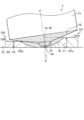
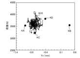
ここで、図10は、テスト軌跡Q1と、テスト軌跡Q2とを示す模式図である。図10に示すように、摩擦攪拌接合を行う前に、一対の金属部材301,302を用いて修正移動ルートR2を生成するためのテスト試行を行う。金属部材301,302は、実際に摩擦攪拌接合を行う第一金属部材101及び第二金属部材102と同じ、若しくは、近い材料、厚さ等であることが好ましい。つまり、第一金属部材101及び第二金属部材102による突合せ部J1と同様に、金属部材301,302同士を突き合わせて突合せ部J30を形成する。すなわち、このテスト試行では、第一金属部材101及び第二金属部材102と比して、同様の材種の金属からなり、同様の板厚寸法を有する板状部材を、同様の高さの段差を形成するようにして突き合わせた、表面の高さ位置が異なる二つの金属部材301,302を用いることが好ましい。 Here, FIG. 10 is a schematic diagram showing a test trajectory Q1 and a test trajectory Q2. As shown in FIG. 10, before performing friction stir welding, a test trial is performed to generate a modified movement route R2 using a pair ofmetal members 301 and 302. It is preferable that themetal members 301 and 302 have the same or similar material, thickness, etc., as thefirst metal member 101 and thesecond metal member 102 to which friction stir welding is actually performed. That is, similarly to the abutting part J1 formed by thefirst metal member 101 and thesecond metal member 102, the abutting part J30 is formed by abutting themetal members 301 and 302 against each other. That is, in this test trial, compared to thefirst metal member 101 and thesecond metal member 102, a plate-like member made of the same type of metal and having the same thickness dimension was It is preferable to use twometal members 301 and 302 having different surface height positions, which are butted against each other so as to form a .

テスト軌跡Q1は、回転ツールFを金属部材301,302に挿入しないで、予め設定された設定移動ルートに従って、試験的に摩擦攪拌装置4を移動させた走行軌跡を示している。つまり、テスト軌跡Q1は、無負荷状態で摩擦攪拌装置4のアームロボット31を移動させた走行軌跡である。このとき、回転ツールを金属部材301,302に挿入せずに無負荷の状態で移動させたものであれば、回転ツールFを取り付けずに移動させたものであってもよい。なお、本明細書において、「走行軌跡」は、単に「軌跡」と称することがある。 The test trajectory Q1 indicates a travel trajectory in which thefriction stirrer 4 was moved experimentally according to a preset movement route without inserting the rotary tool F into themetal members 301, 302. In other words, the test trajectory Q1 is a travel trajectory in which thearm robot 31 of thefriction stirrer 4 is moved in a no-load state. At this time, as long as the rotary tool is moved without inserting it into themetal members 301, 302 and without a load, the rotary tool F may be moved without being attached. Note that in this specification, the "travel trajectory" may be simply referred to as "trajectory."

一方、テスト軌跡Q2は、回転ツールFを金属部材301,302に挿入して、予め設定されたテスト軌跡Q1と同じ設定移動ルートに従って、試験的に摩擦攪拌を行った軌跡である。テスト軌跡Q1とテスト軌跡Q2は、いずれも同じ設定移動ルートにしたがって移動させたにも関わらず、実際に摩擦攪拌を行うことで所定の差分(差分YL)が発生する。ここでの差分は、テスト軌跡Q2がテスト軌跡Q1に対して、接合方向と直行する方向に差分YLだけ略平行に変位している。 On the other hand, the test trajectory Q2 is a trajectory in which the rotary tool F is inserted into themetal members 301, 302 and friction stirring is performed on a trial basis according to the same set movement route as the preset test trajectory Q1. Although the test trajectory Q1 and the test trajectory Q2 are both moved according to the same set movement route, a predetermined difference (difference YL) occurs when friction stirring is actually performed. The difference here is that the test trajectory Q2 is displaced approximately parallel to the test trajectory Q1 by a difference YL in a direction perpendicular to the welding direction.

これは、表面の高さ位置が異なるように突き合わされた二つの金属部材に回転ツールFが接触することで、アームロボット31に生じるたわみによって回転ツールFの位置がテスト軌跡Q1からテスト軌跡Q2に変位することに起因すると推察される。また、アームロボット31の癖、金属部材の材料抵抗等にも影響を受けていると推察される。したがって、摩擦攪拌接合でテスト軌跡Q2を走行させたい場合は、差分YLを考慮して設定移動ルートを設定する必要がある。差分YLは、第一金属部材101及び第二金属部材102の摩擦攪拌接合前に、金属部材に回転ツールFを挿入した状態で摩擦攪拌接合を行ったテスト試行と、無負荷の状態で行ったテスト試行とを行い、これらに基づいて予め算出することができる。より詳しくは、差分YLは、第一金属部材101及び第二金属部材102による突合せ部J1と同様に突合せ部を形成した金属部材に回転ツールFを挿入した状態で摩擦攪拌接合を行いながら回転ツールFを移動させた場合のテスト軌跡Q2と、回転ツールFを金属部材に挿入せずに無負荷の状態で移動させた場合のテスト軌跡Q1との走行軌跡の差分(差分の平均)から算出することができる。なお、テスト軌跡Q1及びテスト軌跡Q2を得るための設定移動ルートは、突き合わせた金属部材の突合せ部J30をテスト軌跡Q2が通過するように設定することが好ましい。特には、テスト軌跡Q2の開始位置付近で突合せ部J30を通過して、突合せ部J30に沿って、厚板の金属部材側に向けて移動するように設定移動ルートを設定することが好ましい。テスト試行を行う際は、金属部材301,302の少なくとも一方に回転ツールFを挿入してテスト軌跡Q1,Q2を取得すればよい。 This is because when the rotary tool F comes into contact with two metal members that are butted against each other so that their surface heights are different, the position of the rotary tool F changes from the test trajectory Q1 to the test trajectory Q2 due to the deflection that occurs in thearm robot 31. It is presumed that this is caused by displacement. It is also inferred that it is influenced by the habits of thearm robot 31, the material resistance of the metal members, etc. Therefore, when it is desired to run the test trajectory Q2 in friction stir welding, it is necessary to set the set movement route in consideration of the difference YL. The difference YL was determined by a test trial in which friction stir welding was performed with the rotary tool F inserted into the metal member before friction stir welding of thefirst metal member 101 and thesecond metal member 102, and a test trial in which friction stir welding was performed in a state with no load. It can be calculated in advance based on test trials. More specifically, the difference YL is calculated by inserting the rotary tool F into a metal member in which a butt part is formed in the same manner as the butt part J1 between thefirst metal member 101 and thesecond metal member 102, and the rotary tool F is inserted while performing friction stir welding. Calculated from the difference in travel trajectory (average of differences) between the test trajectory Q2 when F is moved and the test trajectory Q1 when the rotary tool F is moved without inserting it into a metal member and with no load. be able to. It is preferable that the travel route set for obtaining the test trajectory Q1 and the test trajectory Q2 is set such that the test trajectory Q2 passes through the abutting portion J30 of the abutted metal members. In particular, it is preferable to set the set movement route so as to pass the abutment J30 near the start position of the test trajectory Q2 and move along the abutment J30 toward the metal member side of the thick plate. When performing a test trial, the rotary tool F may be inserted into at least one of themetal members 301 and 302 to obtain test trajectories Q1 and Q2.

修正移動ルート生成部63では、図9に示すように、目標移動ルートR1及び差分YLに基づいて、修正移動ルートR2を算出する。本実施形態では、図10に示すように、回転ツールFを挿入した状態で摩擦攪拌接合を行ったテスト軌跡Q2は、無負荷の状態のテスト軌跡Q1から左側(薄板側)へ差分YLだけ略平行に変位する傾向があるため、修正移動ルートR2は、目標移動ルートR1に対して右側(厚板(第一金属部材101)側)へ差分YLだけ変位させた位置に設定する。言い換えれば、修正移動ルート生成部63は、ツールを挿入した状態での走行軌跡であるテスト軌跡Q2が無負荷の状態での走行軌跡であるテスト軌跡Q1に対して略平行に変位した長さ(差分YL)の分だけ、テスト軌跡Q2が変位した向きとは反対方向に向けて、目標移動ルートR1を略平行に変位させた位置に修正移動ルートR2を設定する。つまり、摩擦攪拌制御部55は、修正移動ルートR2で回転ツールFが移動するように制御することにより、差分YLが吸収されて、目標移動ルートR1上を回転ツールFが移動して、摩擦撹拌接合が行われるようになる。 The corrected movementroute generation unit 63 calculates a corrected movement route R2 based on the target movement route R1 and the difference YL, as shown in FIG. In this embodiment, as shown in FIG. 10, the test trajectory Q2 in which friction stir welding was performed with the rotating tool F inserted is approximately a difference YL to the left (thin plate side) from the test trajectory Q1 in the no-load state. Since there is a tendency for displacement in parallel, the corrected movement route R2 is set at a position displaced by a difference YL to the right (toward the thick plate (first metal member 101) side) with respect to the target movement route R1. In other words, the corrected movementroute generation unit 63 generates the length ( A corrected movement route R2 is set at a position where the target movement route R1 is displaced substantially parallel to the direction in which the test trajectory Q2 is displaced by the difference YL). In other words, the friction stirringcontrol unit 55 controls the rotary tool F to move along the corrected movement route R2, so that the difference YL is absorbed and the rotary tool F moves on the target movement route R1, thereby causing friction stirring. Joining will now take place.

なお、テスト軌跡Q1及びテスト軌跡Q2の差分YLが小さい又は無い場合は、修正移動ルートは設定せずに、目標移動ルートR1に基づいて回転ツールFを移動させてもよい。また、差分YLの取得(算出)は摩擦攪拌接合ごとに行う必要はないが、例えば、回転ツールFを交換する場合、第一金属部材101及び第二金属部材102の板厚寸法、材種、表面の高さ位置等を変更する場合に応じて取得し、差分YLと修正移動ルートR2を算出することが好ましい。 Note that if the difference YL between the test trajectory Q1 and the test trajectory Q2 is small or absent, the rotary tool F may be moved based on the target movement route R1 without setting a corrected movement route. Although it is not necessary to obtain (calculate) the difference YL for each friction stir welding, for example, when replacing the rotary tool F, the plate thickness dimension, material type, etc. of thefirst metal member 101 and thesecond metal member 102, It is preferable to obtain the information in accordance with the case where the height position of the surface, etc. is changed, and calculate the difference YL and the corrected movement route R2.

修正移動ルート生成部63は、判定部64によって摩擦攪拌接合中の回転ツールFの位置が許容範囲M外と判定された場合、摩擦攪拌接合中の回転ツールFの位置に応じて回転ツールFの位置を再設定した修正移動ルートR2を算出することが好ましい。具体的には、摩擦攪拌接合中の回転ツールFのY方向の位置が第一金属部材101側となっていた箇所では、この箇所の回転ツールFの位置が第二金属部材102側となるように修正移動ルートR2を再設定する。同様に、摩擦攪拌接合中の回転ツールFのY方向の位置が第二金属部材102側となっていた箇所では、この箇所の回転ツールFの位置が第一金属部材101側となるように修正移動ルートR2を再設定する。 When thedetermination unit 64 determines that the position of the rotary tool F during friction stir welding is outside the allowable range M, the modified movementroute generation unit 63 adjusts the position of the rotary tool F according to the position of the rotary tool F during friction stir welding. It is preferable to calculate a corrected movement route R2 in which the position is reset. Specifically, in a place where the position of the rotary tool F in the Y direction during friction stir welding was on thefirst metal member 101 side, the position of the rotary tool F at this place is on thesecond metal member 102 side. The corrected movement route R2 is reset. Similarly, in a location where the position of the rotary tool F in the Y direction during friction stir welding was on thesecond metal member 102 side, the position of the rotary tool F at this location is corrected so that it is on thefirst metal member 101 side. Reset travel route R2.

判定部64は、図8に示すように、測定部34から送信される結果が所定の数値範囲内か否かを判定する部位である。つまり、判定部64は、摩擦攪拌接合前の段差寸法h、隙間量D、温度T、回転ツールFの初期位置Yb0がそれぞれ所定の数値範囲内か否かを判定する。また、判定部64は、摩擦攪拌接合中の回転ツールFの位置Ynが所定の数値範囲(許容範囲M)内か否かを判定する。特には、判定部64は、摩擦攪拌接合中の回転ツールFの位置Ynのうち、進行方向に対する左右位置が所定の数値範囲(許容範囲M)内か否かを判定する。また、判定部64は、摩擦攪拌接合後の接合部のバリ高さS及び表面粗さRaの両方が所定の数値範囲内か否かを判定する。また、判定部64は、回転ツールFに作用する軸方向の反力荷重が所定の数値範囲内か否かを判定する。判定部64は、上述した判定項目のうちいずれか一つについて判定を行うようにしてもよく、上述した判定項目から二つ以上を組み合わせたものについて判定を行うようにしてもよい。例えば、判定部64は、摩擦攪拌接合中の回転ツールFの位置Yn及び摩擦攪拌接合中の荷重の少なくとも一方に対して、所定の数値範囲内であるか否かを判定するようにしてもよい。本実施形態では、摩擦攪拌接合前のセット状態(段差寸法h、隙間量D、温度T、回転ツールFの初期位置Yb0)、摩擦攪拌接合中の回転ツールFの位置Yn、摩擦攪拌接合後の接合部のバリ高さS及び表面粗さRaについて判定を行う場合を例示して説明する。 As shown in FIG. 8, the determiningunit 64 is a part that determines whether the result transmitted from the measuringunit 34 is within a predetermined numerical range. That is, the determiningunit 64 determines whether the step dimension h, the gap amount D, the temperature T, and the initial position Yb0 of the rotary tool F before friction stir welding are each within a predetermined numerical range. Further, thedetermination unit 64 determines whether the position Yn of the rotary tool F during friction stir welding is within a predetermined numerical range (tolerable range M). In particular, thedetermination unit 64 determines whether or not the left and right positions with respect to the advancing direction of the position Yn of the rotary tool F during friction stir welding are within a predetermined numerical range (tolerable range M). Further, thedetermination unit 64 determines whether both the burr height S and the surface roughness Ra of the welded portion after friction stir welding are within a predetermined numerical range. Further, thedetermination unit 64 determines whether the axial reaction force load acting on the rotary tool F is within a predetermined numerical range. Thedetermination unit 64 may make a determination on any one of the above-mentioned determination items, or may make a determination on a combination of two or more of the above-mentioned determination items. For example, thedetermination unit 64 may determine whether at least one of the position Yn of the rotary tool F during friction stir welding and the load during friction stir welding is within a predetermined numerical range. . In this embodiment, the set state before friction stir welding (step dimension h, gap amount D, temperature T, initial position Yb0 of rotary tool F), position Yn of rotary tool F during friction stir welding, and after friction stir welding An example will be described in which the burr height S and surface roughness Ra of the joint are determined.

<段差寸法h>
判定部64は、摩擦攪拌接合を行う前に測定部34を突合せ部J1に沿って移動させることで、測定部34から送信された結果(段差寸法h(mm))が、所定の数値範囲内か否かを判定する。
<Step dimension h>
The determiningunit 64 moves the measuringunit 34 along the abutting portion J1 before performing friction stir welding, so that the result (step dimension h (mm)) sent from the measuringunit 34 is within a predetermined numerical range. Determine whether or not.

本実施形態では、第一金属部材101の板厚寸法は2.0mmであり、第二金属部材102の板厚寸法は1.2mmに設定しているため、設定段差寸法は0.8mmである。段差寸法hの所定の数値範囲は適宜設定すればよいが、例えば、第一金属部材101及び第二金属部材102の設定段差寸法hが0.8mmである場合、0.75≦h≦0.93と設定することができる。判定対象となる段差寸法hは、測定部34で取得された全数でもよいし、接合長全体に対する段差寸法の平均値であってもよいし、最大値であってもよいし、もしくは所定間隔ごとの複数の段差寸法を抽出してそれぞれ判定してもよい。 In this embodiment, the plate thickness of thefirst metal member 101 is 2.0 mm, and the plate thickness of thesecond metal member 102 is set to 1.2 mm, so the set step size is 0.8 mm. . The predetermined numerical range of the step size h may be set as appropriate, but for example, when the set step size h of thefirst metal member 101 and thesecond metal member 102 is 0.8 mm, 0.75≦h≦0. It can be set to 93. The step dimension h to be determined may be the total number obtained by themeasurement unit 34, the average value of the step dimensions for the entire joint length, the maximum value, or the step size measured at predetermined intervals. A plurality of step dimensions may be extracted and determined individually.

判定部64は、段差寸法hを所定の数値範囲外と判定した場合、その第一金属部材101及び第二金属部材102をワーク番号と関連付けて数値範囲外品と判定する。判定部64は、当該判定結果を主制御部41に送信するとともに記憶部44に格納する。当該判定結果は、表示部43に表示させるようにしてもよいし、判定結果に応じて音や光などを出力する報知手段で報知するようにしてもよい。 When determining that the step dimension h is outside the predetermined numerical range, the determiningunit 64 associates thefirst metal member 101 and thesecond metal member 102 with the workpiece number, and determines that they are out of the numerical range. Thedetermination section 64 transmits the determination result to themain control section 41 and stores it in thestorage section 44 . The determination result may be displayed on thedisplay unit 43, or may be notified by a notification means that outputs sound, light, etc. according to the determination result.

<隙間量D>
また、判定部64は、摩擦攪拌接合を行う前に測定部34を突合せ部J1に沿って移動させることで、測定部34から送信された隙間量D(mm)が、所定の数値範囲内か否かを判定する。隙間量Dの所定範囲は適宜設定すればよいが、例えば、0≦D≦0.4と設定することができる。判定する隙間量Dは、測定部34で取得された全数でもよいし、接合長全体に対する隙間量の平均値でもよいし、最大値であってもよいし、もしくは所定間隔ごとの複数の隙間量を抽出してそれぞれ判定してもよい。
<Gap amount D>
Furthermore, by moving the measuringunit 34 along the butt portion J1 before performing friction stir welding, the determiningunit 64 determines whether the gap amount D (mm) transmitted from the measuringunit 34 is within a predetermined numerical range. Determine whether or not. The predetermined range of the gap amount D may be set as appropriate, and may be set as 0≦D≦0.4, for example. The gap amount D to be determined may be the total number obtained by themeasurement unit 34, the average value of the gap amounts for the entire joint length, the maximum value, or a plurality of gap amounts at predetermined intervals. You may extract and judge each.

判定部64は、隙間量Dを所定の数値範囲外と判定した場合、その第一金属部材101及び第二金属部材102をワーク番号と関連付けて数値範囲外品と判定する。判定部64は、当該判定結果を主制御部41に送信するとともに記憶部44に格納する。当該判定結果は、表示部43に表示させるようにしてもよいし、判定結果に応じて音や光などを出力する報知手段で報知するようにしてもよい。 When thedetermination unit 64 determines that the gap amount D is outside the predetermined numerical range, thedetermination unit 64 associates thefirst metal member 101 and thesecond metal member 102 with the workpiece number, and determines that thefirst metal member 101 and thesecond metal member 102 are products outside the numerical value range. Thedetermination section 64 transmits the determination result to themain control section 41 and stores it in thestorage section 44 . The determination result may be displayed on thedisplay unit 43, or may be notified by a notification means that outputs sound, light, etc. according to the determination result.

<初期位置>
また、判定部64は、摩擦攪拌接合を行う前に、測定部34によって回転ツールFの初期位置Yb0を測定することで、測定部34から送信された初期位置Yb0が、修正移動ルートR2の開始位置に対して所定の数値範囲内か否かを判定する。初期位置Yb0の所定
範囲は適宜設定すればよいが、修正移動ルートR2の開始位置を中心として、例えば、0mm以上、0.3mm以下の範囲内と設定することができる。特には、修正移動ルートR2の開始位置を中心として、Y方向に0mm以上、0.3mm以下の範囲内と設定することができる。
<Initial position>
In addition, the determiningunit 64 determines that the initial position Yb0 of the rotary tool F is measured by the measuringunit 34 before performing friction stir welding, so that the initial position Yb0 transmitted from the measuringunit 34 is the start of the corrected movement route R2. It is determined whether the position is within a predetermined numerical range. The predetermined range of the initial position Yb0 may be set as appropriate, but may be set within a range of, for example, 0 mm or more and 0.3 mm or less, centered on the starting position of the corrected movement route R2. In particular, it can be set within a range of 0 mm or more and 0.3 mm or less in the Y direction centering on the starting position of the corrected movement route R2.

判定部64は、初期位置Yb0を所定の数値範囲外と判定した場合、その第一金属部材101及び第二金属部材102をワーク番号と関連付けて数値範囲外品と判定する。判定部64は、当該判定結果を主制御部41に送信するとともに記憶部44に格納する。当該判定結果は、表示部43に表示させるようにしてもよいし、判定結果に応じて音や光などを出力する報知手段で報知するようにしてもよい。 When thedetermination unit 64 determines that the initial position Yb0 is outside the predetermined numerical value range, thedetermination unit 64 associates thefirst metal member 101 and thesecond metal member 102 with the workpiece number and determines that thefirst metal member 101 and thesecond metal member 102 are out of the numerical value range. Thedetermination section 64 transmits the determination result to themain control section 41 and stores it in thestorage section 44 . The determination result may be displayed on thedisplay unit 43, or may be notified by a notification means that outputs sound, light, etc. according to the determination result.

<許容範囲M>
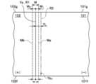
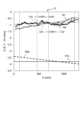
また、判定部64は、摩擦攪拌接合中に測定部34から送信された回転ツールFの位置Ynが、許容範囲(数値範囲)M内か否かを判定する。図11は、摩擦攪拌接合を行った後の回転ツールFの位置Yn(走行軌跡)を示す模式図である。図11では、説明の便宜上、Y方向の移動が理解しやすいようにX方向とY方向の縮尺を変更して描画している。図11では、図中の下側から上側に向けて回転ツールFを移動させており、回転ツールFの位置Ynは許容範囲M内を移動している。
<Tolerance range M>
Further, the determiningunit 64 determines whether the position Yn of the rotary tool F transmitted from the measuringunit 34 during friction stir welding is within the allowable range (numerical range) M. FIG. 11 is a schematic diagram showing the position Yn (traveling trajectory) of the rotary tool F after performing friction stir welding. In FIG. 11, for convenience of explanation, the scales in the X direction and the Y direction are changed to make it easier to understand the movement in the Y direction. In FIG. 11, the rotary tool F is moved from the bottom to the top in the figure, and the position Yn of the rotary tool F is moved within the tolerance range M.

許容範囲Mの範囲は適宜設定すればよいが、例えば、稜線位置Ypの全長方向に対して稜線位置Ypを中心としたY方向の第一金属部材101側に0.6mm(m=0.6)、第二金属部材102側に0.3mm(m=0.3)となる位置で囲まれた領域と設定することができる。 The range of the allowable range M may be set as appropriate, but for example, 0.6 mm (m=0.6 ), it can be set as an area surrounded by a position of 0.3 mm (m=0.3) on thesecond metal member 102 side.

判定部64は、摩擦攪拌接合中の回転ツールFの位置Ynを許容範囲(数値範囲)M外と判定した場合、その第一金属部材101及び第二金属部材102をワーク番号と関連付けて数値範囲外品と判定する。判定部64は、当該判定結果を主制御部41に送信するとともに記憶部44に格納する。当該判定結果は、表示部43に表示させるようにしてもよいし、判定結果に応じて音や光などを出力する報知手段で報知するようにしてもよい。 When thedetermination unit 64 determines that the position Yn of the rotary tool F during friction stir welding is outside the allowable range (numerical range) M, thedetermination unit 64 associates thefirst metal member 101 and thesecond metal member 102 with the workpiece number and determines the numerical value range. It is judged to be a foreign product. Thedetermination unit 64 transmits the determination result to themain control unit 41 and stores it in thestorage unit 44 . The determination result may be displayed on thedisplay unit 43, or may be notified by a notification means that outputs sound, light, etc. according to the determination result.

<バリ高さS及び表面粗さRa>
また、判定部64は、摩擦攪拌接合後において、摩擦攪拌装置4の測定部(検査部)34を接合部(塑性化領域W)に沿って移動させることによって得られたバリ高さS及び表面粗さRaの両方が所定の数値範囲内か否かを判定する。バリ高さSは適宜設定すればよいが、例えば、0≦S≦0.1mmに設定することができる。また、表面粗さRaは適宜設定すればよいが、例えば、0≦Ra≦5.0μmに設定することができる。判定するバリ高さS及び表面粗さRaは、測定部34で取得された全数でもよいし、接合長全体に対する平均値でもよいし、最大値であってもよいし、もしくは所定間隔ごとの複数のバリ高さS及び表面粗さRaを抽出してそれぞれ判定してもよい。
<Burr height S and surface roughness Ra>
In addition, after friction stir welding, thedetermination unit 64 determines the burr height S and the surface It is determined whether both roughnesses Ra are within a predetermined numerical range. The burr height S may be set as appropriate, and may be set to 0≦S≦0.1 mm, for example. Further, the surface roughness Ra may be set as appropriate, and may be set to, for example, 0≦Ra≦5.0 μm. The burr height S and surface roughness Ra to be determined may be the total number obtained by themeasurement unit 34, the average value for the entire bond length, the maximum value, or a plurality of values at predetermined intervals. The burr height S and surface roughness Ra may be extracted and determined respectively.

図12は、本実施形態に係る回転ツールの挿入状態を示す断面図である。図12に示すように、摩擦攪拌接合中においては、回転ツールFを鉛直線に対して第二金属部材102側に所定の狙い角度θで傾けた状態で移動させる。回転ツールFの走行軌跡には塑性化領域Wが形成されている。狙い角度θは、適宜設定すればよい。本実施形態では、例えば、上方から見た場合に先端側ピンF3の平坦面の中心F5が目標移動ルートR1と重なるように設定している。 FIG. 12 is a sectional view showing the inserted state of the rotary tool according to this embodiment. As shown in FIG. 12, during friction stir welding, the rotary tool F is moved while being inclined at a predetermined target angle θ toward thesecond metal member 102 with respect to the vertical line. A plasticized region W is formed in the traveling locus of the rotary tool F. The aiming angle θ may be set appropriately. In this embodiment, for example, the center F5 of the flat surface of the tip end pin F3 is set to overlap with the target movement route R1 when viewed from above.

摩擦攪拌接合における挿入深さは、適宜設定すればよいが、本実施形態では基端側ピンF2の外周面を第一金属部材101の表面101b及び第二金属部材102の表面102bにそれぞれ接触させつつ、先端側ピンF3が架台21に接触しない程度に設定している。 The insertion depth in friction stir welding may be set appropriately, but in this embodiment, the outer peripheral surface of the proximal pin F2 is brought into contact with thesurface 101b of thefirst metal member 101 and thesurface 102b of thesecond metal member 102, respectively. At the same time, the tip end side pin F3 is set to such an extent that it does not come into contact with thepedestal 21.

本実施形態では、回転ツールFを右回転させて、進行方向右側に第一金属部材101が位置するように回転ツールFの回転方向及び進行方向を設定している。回転ツールFの回転方向及び進行方向は適宜設定すればよいが、本実施形態では回転ツールFの走行軌跡に形成される塑性化領域Wのうち、第二金属部材102側がシアー側となり、第一金属部材101側がフロー側となるように設定している。 In this embodiment, the rotating direction and advancing direction of the rotating tool F are set so that the rotating tool F is rotated clockwise and thefirst metal member 101 is located on the right side in the advancing direction. The rotational direction and traveling direction of the rotary tool F may be set appropriately, but in this embodiment, thesecond metal member 102 side is the shear side of the plasticized region W formed in the travel locus of the rotary tool F, and thefirst metal member 102 side is the shear side. Themetal member 101 side is set to be the flow side.

なお、シアー側(Advancing side:アドバンシング側)とは、被接合部に対する回転ツールの外周の相対速度が、回転ツールの外周における接線速度の大きさに移動速度の大きさを加算した値となる側を意味する。一方、フロー側(Retreating side:リトリーティング側)とは、回転ツールの移動方向の反対方向に回転ツールが回動することで、被接合部に対する回転ツールの相対速度が低速になる側を言う。 In addition, the shear side (Advancing side) means that the relative speed of the outer circumference of the rotary tool to the part to be welded is the value obtained by adding the magnitude of the moving speed to the magnitude of the tangential velocity at the outer circumference of the rotary tool. means side. On the other hand, the flow side (Retreating side) refers to the side where the rotation tool rotates in the opposite direction to the moving direction of the rotation tool, so that the relative speed of the rotation tool with respect to the welded part becomes low.

なお、本実施形態の自動接合システム1では、例えば、摩擦攪拌接合を行う際に、回転ツールFの傾斜角度を進行方向に対して所定の角度で前傾又は後傾させてもよい。 In addition, in theautomatic welding system 1 of this embodiment, when performing friction stir welding, for example, the inclination angle of the rotary tool F may be tilted forward or backward at a predetermined angle with respect to the traveling direction.

[B-2.動作フロー]
次に、本実施形態に係る自動接合システム1の動作フローの一例について説明する。図13は、本実施形態に係る自動接合システムの動作の一例を示すフローチャートである。本実施形態に係る自動接合システム1では、制御装置5から各装置に送信される制御信号に基づいて自動で摩擦攪拌接合を行う。
[B-2. Operation flow]
Next, an example of the operation flow of the automatic joiningsystem 1 according to this embodiment will be described. FIG. 13 is a flowchart showing an example of the operation of the automatic joining system according to this embodiment. In theautomatic welding system 1 according to this embodiment, friction stir welding is automatically performed based on control signals sent from thecontrol device 5 to each device.

図13に示すように、ステップST1において、搬送制御部51は、搬送装置2を制御して第一金属部材101及び第二金属部材102を固定装置3の所定位置に搬送させる。第一金属部材101及び第二金属部材102はクランプ部24で固定されるとともに、吸引部22によって第二金属部材102の端部が吸引される。 As shown in FIG. 13, in step ST1, thetransport control unit 51 controls thetransport device 2 to transport thefirst metal member 101 and thesecond metal member 102 to a predetermined position of the fixingdevice 3. Thefirst metal member 101 and thesecond metal member 102 are fixed by theclamp part 24, and the end of thesecond metal member 102 is sucked by thesuction part 22.

ステップST2において、摩擦攪拌制御部55は、摩擦攪拌装置4の測定部34を突合せ部J1に沿って移動させて固定状態(セット状態)を測定させる。つまり、測定部34で、段差寸法h、隙間量D及び第一金属部材101の稜線101eを測定する。また、測定部34で、回転ツールFの初期位置Yb0を測定する。測定部34は測定結果を摩擦攪拌制御部55に送信する。また、温度調整部23の温度センサ23aは、測定結果を温度制御部53に送信する。 In step ST2, the frictionstir control section 55 moves themeasurement section 34 of thefriction stir device 4 along the abutting section J1 to measure the fixed state (set state). That is, themeasurement unit 34 measures the step dimension h, the gap amount D, and theridgeline 101e of thefirst metal member 101. Further, the measuringunit 34 measures the initial position Yb0 of the rotary tool F. Themeasurement section 34 transmits the measurement results to the frictionstir control section 55. Further, thetemperature sensor 23a of thetemperature adjustment section 23 transmits the measurement result to thetemperature control section 53.

ステップST3において、温度制御部53の判定部66及び摩擦攪拌制御部55の判定部64は、第一金属部材101及び第二金属部材102のセット状態が所定の数値範囲内か否かをそれぞれ判定する。判定部64,66が、段差寸法h、隙間量D、温度T、回転ツールFの初期位置Yb0の全てを数値範囲内と判定した場合(ステップST3のYES)、ステップST5に移行する。段差寸法h、隙間量D、温度T、及び回転ツールFの初期位置Yb0の少なくとも一つが数値範囲外と判定された場合(ステップST3のNO)、判定部64又は判定部66はワーク番号と関連付けてその第一金属部材101及び第二金属部材102を数値範囲外品と判定し(ステップST4)、ステップST5に移行する。 In step ST3, thedetermination unit 66 of thetemperature control unit 53 and thedetermination unit 64 of the frictionstir control unit 55 respectively determine whether the set states of thefirst metal member 101 and thesecond metal member 102 are within a predetermined numerical range. do. When thedetermination units 64 and 66 determine that the step dimension h, the gap amount D, the temperature T, and the initial position Yb0 of the rotary tool F are all within the numerical range (YES in step ST3), the process proceeds to step ST5. When it is determined that at least one of the step dimension h, the gap amount D, the temperature T, and the initial position Yb0 of the rotary tool F is outside the numerical range (NO in step ST3), thedetermination unit 64 or 66 associates it with the workpiece number. Then, thefirst metal member 101 and thesecond metal member 102 are determined to be out of the numerical value range (step ST4), and the process moves to step ST5.

ステップST5において、摩擦攪拌制御部55(修正移動ルート生成部63)は、稜線位置Yp及び予め取得した差分YLに基づいて修正移動ルートR2を生成する。具体的には、稜線位置Ypを目標移動ルートR1として算出するとともに、目標移動ルートR1に対して厚板側へ略平行に差分YLだけ変位させた位置に修正移動ルートR2を設定する。 In step ST5, the friction stir control unit 55 (corrected movement route generation unit 63) generates a corrected movement route R2 based on the ridgeline position Yp and the difference YL obtained in advance. Specifically, the ridgeline position Yp is calculated as the target movement route R1, and a corrected movement route R2 is set at a position displaced approximately parallel to the thick plate side by a difference YL with respect to the target movement route R1.

ステップST6において、摩擦攪拌制御部55は、摩擦攪拌装置4を制御して所定の回転速度で回転する回転ツールFを第一金属部材101及び第二金属部材102に挿入して移動させることで摩擦攪拌接合を行わせる。具体的には、摩擦攪拌制御部55は、回転ツールFを修正移動ルートR2に沿って移動するように制御する。このとき、第一金属部材101及び第二金属部材102への回転ツールFの挿入に伴い、回転ツールFの位置は、修正移動ルートR2の開始位置付近となる挿入前の初期位置Yb0から第二金属部材102側に差分YLの変位が生じて、稜線位置Yp付近に移動する。このようにして、回転ツールFが目標移動ルートR1に沿って移動するようにして摩擦攪拌接合が行われる。 In step ST6, the frictionstir control unit 55 controls thefriction stir device 4 to insert and move the rotary tool F, which rotates at a predetermined rotational speed, into thefirst metal member 101 and thesecond metal member 102, thereby causing friction. Perform stirring welding. Specifically, the frictionstir control unit 55 controls the rotary tool F to move along the corrected movement route R2. At this time, as the rotary tool F is inserted into thefirst metal member 101 and thesecond metal member 102, the position of the rotary tool F changes from the initial position Yb0 before insertion, which is near the start position of the corrected movement route R2, to the second position. A displacement of the difference YL occurs on themetal member 102 side, and themetal member 102 moves to the vicinity of the ridgeline position Yp. In this way, friction stir welding is performed with the rotary tool F moving along the target movement route R1.

ステップST7において、摩擦攪拌制御部55の判定部64は、摩擦攪拌接合中の回転ツールFの位置Ynが、許容範囲(数値範囲)M内か否かを判定する。判定部64が、回転ツールFの位置Ynを許容範囲M内であると判定した場合(ステップST7のYES)、ステップST9に移行する。摩擦攪拌接合中の回転ツールFの位置Ynが一部でも許容範囲M外であると判定された場合(ステップST7のNO)、判定部64はワーク番号と関連付けてその第一金属部材101及び第二金属部材102を数値範囲外品と判定し(ステップST8)、ステップST9に移行する。 In step ST7, thedetermination unit 64 of the frictionstir control unit 55 determines whether the position Yn of the rotary tool F during friction stir welding is within the allowable range (numerical range) M. When thedetermination unit 64 determines that the position Yn of the rotary tool F is within the allowable range M (YES in step ST7), the process moves to step ST9. If it is determined that even a part of the position Yn of the rotary tool F during friction stir welding is outside the allowable range M (NO in step ST7), thedetermination unit 64 associates thefirst metal member 101 and thefirst metal member 101 with the workpiece number. Thebimetallic member 102 is determined to be outside the numerical value range (step ST8), and the process moves to step ST9.

ステップST9において、摩擦攪拌接合が終了した後、摩擦攪拌制御部55は、摩擦攪拌装置4の測定部34を突合せ部J1に沿って移動させてバリ高さS及び表面粗さRaを測定させる。 In step ST9, after the friction stir welding is completed, the frictionstir control unit 55 moves themeasurement unit 34 of thefriction stir device 4 along the abutting portion J1 to measure the burr height S and surface roughness Ra.

ステップST10において、摩擦攪拌制御部55の判定部64は、摩擦攪拌接合後のバリ高さS及び表面粗さRaの両方が所定の数値範囲内か否かを判定する。バリ高さS及び表面粗さRaの両方が所定の数値範囲内であると判定された場合(ステップST10のYES)、ステップST12に移行する。バリ高さS及び表面粗さRaの少なくとも一方が所定の数値範囲外と判定された場合(ステップST10のNO)、判定部64はワーク番号と関連付けてその被接合金属部材103を数値範囲外品と判定し(ステップST11)、ステップST12に移行する。 In step ST10, thedetermination unit 64 of the frictionstir control unit 55 determines whether both the burr height S and the surface roughness Ra after friction stir welding are within a predetermined numerical range. If it is determined that both the burr height S and the surface roughness Ra are within the predetermined numerical range (YES in step ST10), the process moves to step ST12. When it is determined that at least one of the burr height S and the surface roughness Ra is outside the predetermined numerical range (NO in step ST10), thedetermination unit 64 associates it with the workpiece number and classifies the metal member 103 to be welded as a product outside the numerical range. It is determined that (step ST11), and the process moves to step ST12.

ステップST12において、主制御部41は、一の摩擦攪拌接合工程中に数値範囲外品との判定を一度も受けていないか判定する。主制御部41が、数値範囲外品との判定を一度も受けていないと判定した場合(ステップST12のYES)、ステップST13に移行する。主制御部41が、数値範囲外品の判定を一度でも受けたと判定した場合(ステップST12のNO)、ステップST14に移行する。 In step ST12, themain control unit 41 determines whether the product has never been determined to be outside the numerical range during one friction stir welding process. When themain control unit 41 determines that the product has never been determined to be a product outside the numerical value range (YES in step ST12), the process moves to step ST13. If themain control unit 41 determines that the product has been determined to be outside the numerical value range even once (NO in step ST12), the process moves to step ST14.

ステップST13において、搬送制御部51は、搬送装置2を制御して被接合金属部材103を取り出し、被接合金属部材103を合格品配置エリア15(図6参照)に配置して終了する。 In step ST13, thetransport control unit 51 controls thetransport device 2 to take out the metal member 103 to be welded, arranges the metal member 103 to be welded in the accepted product placement area 15 (see FIG. 6), and ends the process.

ステップST14において、搬送制御部51は、搬送装置2を制御して被接合金属部材103を取り出し、被接合金属部材103を数値範囲外品として数値範囲外品配置エリア16に配置して終了する。 In step ST14, thetransport control unit 51 controls thetransport device 2 to take out the metal member 103 to be welded, and arranges the metal member 103 to be welded as a product outside the numerical value range in theproduct placement area 16 for the product outside the numerical value range, and ends the process.

以上本実施形態の動作フローの一例を説明したが、適宜変更が可能である。例えば、ステップST3においてセット状態に不具合がある場合、つまり、段差寸法h、隙間量Dが所定の数値範囲外である場合、クランプ部24を解除して、例えば、アームロボット11で第一金属部材101及び第二金属部材102の位置の修正を行ってもよいし、第一金属部材101及び第二金属部材102を固定装置3から取り出して、新たな第一金属部材101及び第二金属部材102を配置してもよい。また、ステップST3において、回転ツールFの初期位置Yb0が所定の数値範囲外である場合、回転ツールFの位置の調整を行ってもよい。 Although an example of the operation flow of this embodiment has been described above, changes can be made as appropriate. For example, if there is a problem with the set state in step ST3, that is, if the step dimension h and the gap amount D are outside the predetermined numerical range, theclamp part 24 is released, and thearm robot 11, for example, The positions of thefirst metal member 101 and thesecond metal member 102 may be corrected, or thefirst metal member 101 and thesecond metal member 102 may be taken out from the fixingdevice 3 and replaced with newfirst metal members 101 andsecond metal members 102. may be placed. Further, in step ST3, if the initial position Yb0 of the rotary tool F is outside the predetermined numerical range, the position of the rotary tool F may be adjusted.

また、ステップST3において、段差寸法h、隙間量D、温度T、及び回転ツールFの初期位置Yb0を判定しているが、これらの少なくとも一つを判定対象としてもよい。また、ステップST3において、温度Tが所定の数値範囲外であると判定された場合、温度調整部23によって加熱又は冷却して温度Tが所定の数値範囲内になってからステップST5に移行するようにしてもよい。なお、温度調整部23による温度Tの判定、及び加熱又は冷却は、摩擦攪拌接合工程中に行うようにしてもよい。 Further, in step ST3, the step size h, the gap amount D, the temperature T, and the initial position Yb0 of the rotary tool F are determined, but at least one of these may be determined. Further, if it is determined in step ST3 that the temperature T is outside the predetermined numerical range, thetemperature adjustment section 23 heats or cools the temperature T until it falls within the predetermined numerical range before proceeding to step ST5. You may also do so. Note that the determination of the temperature T and the heating or cooling by thetemperature adjustment section 23 may be performed during the friction stir welding process.

また、ステップST3及びステップST7においてNOと判定された場合、自動接合システム1を停止させたり、当該判定結果を表示部43に表示させたり、さらには、判定結果に応じて音や光などを出力する報知手段で報知するようにしてもよい。 Further, if the determination is NO in step ST3 and step ST7, the automatic joiningsystem 1 is stopped, the determination result is displayed on thedisplay unit 43, and furthermore, sound, light, etc. are outputted according to the determination result. The notification may be made using a notification means.

また、図13のフローチャートを参照した動作フローの説明では省略したが、ステップST5における、修正移動ルート生成部63による修正移動ルートR2の生成に先立って、差分YLを取得しておくことが好ましい。差分YLの取得は、まず、目標移動ルート生成部61が目標移動ルートR1を設定し、設定移動ルート生成部65が設定移動ルートを生成する。次に、生成された設定移動ルートに従って、金属部材301,302に回転ツールFを挿入しないで無負荷の状態で移動させたテスト軌跡Q1と、金属部材301,302に回転ツールFを挿入して摩擦攪拌接合を行いながら移動させたテスト軌跡Q2とをそれぞれ得る。そして、テスト軌跡Q1とテスト軌跡Q2との差分から、差分YLを取得する。差分YLの取得は、ステップST5よりも前のタイミングで行えばよいが、第一金属部材101及び第二金属部材102をセットするステップST1よりも前に予め行っておくことが好ましい。 Further, although omitted in the explanation of the operation flow with reference to the flowchart of FIG. 13, it is preferable to obtain the difference YL prior to the generation of the corrected movement route R2 by the corrected movementroute generation unit 63 in step ST5. To obtain the difference YL, first, the target travelroute generation section 61 sets the target travel route R1, and the set travelroute generation section 65 generates the set travel route. Next, according to the generated set movement route, a test trajectory Q1 in which the rotating tool F is moved without inserting the rotating tool F into themetal members 301 and 302 and a test trajectory Q1 in which the rotating tool F is moved in an unloaded state without inserting the rotating tool F into themetal members 301 and 302 is created. A test locus Q2 is obtained while performing friction stir welding. Then, a difference YL is obtained from the difference between the test trajectory Q1 and the test trajectory Q2. Although the difference YL may be obtained at a timing before step ST5, it is preferable to obtain the difference YL before step ST1 in which thefirst metal member 101 and thesecond metal member 102 are set.

[B-3.作用効果]
第一金属部材101の稜線101e(図7参照)は、本来直線であることが好ましいが、公差等もあり厳密には直線にはなっていない。また、搬送装置2で第一金属部材101及び第二金属部材102を架台21に搬送し固定する際に、固定位置(セット位置)がずれることもある。したがって、架台21に設定された基準位置Y0(図6参照)をなぞるように回転ツールFを直線移動させたとしても、実際にセットされた突合せ部J1から回転ツールFがずれてしまい、接合品質が低下するおそれがある。特に、本実施形態のように第一金属部材101と第二金属部材102との表面101b,102bの高さ位置が異なる場合、接合位置がわずかにずれるだけでも不具合が発生する傾向がある。
[B-3. Effect]
Although it is preferable that theridge line 101e (see FIG. 7) of thefirst metal member 101 is originally a straight line, it is not strictly a straight line due to tolerances and the like. Further, when thefirst metal member 101 and thesecond metal member 102 are transported and fixed to thepedestal 21 by thetransport device 2, the fixing position (set position) may shift. Therefore, even if the rotary tool F is moved linearly so as to trace the reference position Y0 (see FIG. 6) set on thepedestal 21, the rotary tool F will deviate from the abutting portion J1 that is actually set, resulting in poor joining quality. may decrease. In particular, when the height positions of thesurfaces 101b and 102b of thefirst metal member 101 and thesecond metal member 102 are different as in this embodiment, even a slight shift in the joining position tends to cause problems.

しかし、本発明者らの検討により、突合せ部J1の摩擦撹拌接合を行う際に回転ツールFが実際に移動する位置の軌跡は、回転ツールFの移動が制御される位置の軌跡に対して、第二金属部材102側(薄板側)に向けて略平行に変位していることが見いだされた。このような略平行の変位は、主として、表面の高さ位置が異なるように突き合わされた二つの金属部材のセット状態に起因して生じると考えられる。すなわち、第一金属部材101,301と第二金属部材102,302とは、第一金属部材101,301の表面が第二金属部材102,302の表面よりも高くなるように端面同士を突き合わせて段差を備えた突合せ部J1,J30が形成されている。このようにセットされた状態において、回転ツールFを挿入した状態で摩擦攪拌接合を行う場合、回転ツールFが厚板側の第一金属部材101,301からの反力を受けることで、回転ツールFの位置が、接合長さの全体にわたって薄板側の第二金属部材102,302側へと移動する。このようにして、略平行の変位が生じると考えられる。 However, the inventors' studies have revealed that the locus of the position where the rotary tool F actually moves when performing friction stir welding of the butt portion J1 is different from the locus of the position where the movement of the rotary tool F is controlled. It was found that it was displaced substantially parallel toward thesecond metal member 102 side (thin plate side). It is thought that such a substantially parallel displacement occurs mainly due to the set state of two metal members that are butted against each other so that their surface height positions are different. That is, thefirst metal member 101, 301 and thesecond metal member 102, 302 are placed such that their end surfaces are butted together such that the surface of thefirst metal member 101, 301 is higher than the surface of thesecond metal member 102, 302. Abutting portions J1 and J30 with steps are formed. When performing friction stir welding with the rotary tool F inserted in this set state, the rotary tool F receives a reaction force from thefirst metal member 101, 301 on the thick plate side. The position of F moves toward thesecond metal member 102, 302 on the thin plate side over the entire joining length. In this way, it is believed that a substantially parallel displacement occurs.

本実施形態に係る自動接合システム1によれば、摩擦攪拌接合を行う前に測定した第一金属部材101の稜線位置Ypに基づいて回転ツールFの目標移動ルートR1を設定するとともに、目標移動ルートR1に対して第一金属部材101側(厚板側)に略平行に変位させた位置に修正移動ルートR2を設定する。そして、回転ツールFを修正移動ルートR2に沿って移動するように制御することで、回転ツールFを目標移動ルートR1に沿って摩擦攪拌接合を行うことができるようになった。このように、セットされた第一金属部材101ごとの稜線位置Ypに基づいて、突合せ部J1の摩擦撹拌接合を行う際に生じる変位を補償した位置に回転ツールFを移動するように制御することで、回転ツールFの変位を抑えた的確な移動ルートを容易に設定することができる。これにより接合品質を高めることができる。特には、本実施形態では、ツールを挿入した状態での走行軌跡であるテスト軌跡Q2と、無負荷の状態での走行軌跡であるテスト軌跡Q1との差分YLの長さに基づいて、目標移動ルートR1を略平行に変位させた位置に修正移動ルートR2を設定する。これにより、金属部材101,102のセット状態に応じて生じる、回転ツールFの走行軌跡の略平行の変位を抑えた移動ルートを設定して、接合品質を高めることができる。 According to theautomatic welding system 1 according to the present embodiment, the target movement route R1 of the rotary tool F is set based on the ridgeline position Yp of thefirst metal member 101 measured before performing friction stir welding, and the target movement route A correction movement route R2 is set at a position displaced approximately parallel to thefirst metal member 101 side (thick plate side) with respect to R1. By controlling the rotary tool F to move along the corrected movement route R2, it became possible to perform friction stir welding using the rotary tool F along the target movement route R1. In this way, based on the ridge line position Yp of each setfirst metal member 101, the rotary tool F is controlled to be moved to a position that compensates for the displacement that occurs when performing friction stir welding of the abutting portion J1. Therefore, it is possible to easily set an accurate movement route that suppresses displacement of the rotary tool F. This makes it possible to improve bonding quality. In particular, in this embodiment, the target movement is determined based on the length of the difference YL between the test trajectory Q2, which is the trajectory with the tool inserted, and the test trajectory Q1, which is the trajectory with no load. A corrected movement route R2 is set at a position where the route R1 is displaced approximately parallel to the route R1. As a result, it is possible to set a movement route that suppresses the substantially parallel displacement of the traveling locus of the rotary tool F that occurs depending on the set state of themetal members 101 and 102, thereby improving the joining quality.

また、アームロボット31は、機械のたわみ、癖等があるとともに、回転ツールFが第一金属部材101及び第二金属部材102から受ける抵抗もあるため、制御装置5が設定した修正移動ルートR2に対して、回転ツールFが実際に移動するルートが目標移動ルートR1とずれる場合がある。この点、本実施形態では、稜線位置Ypに基づいた目標移動ルートR1と、予め算出された差分YLに基づいて修正移動ルートR2を設定することにより、回転ツールFが実際に移動するルートをより的確に設定することができる。このとき、本実施形態の目標移動ルートR1又は修正移動ルートR2によれば、その第一金属部材101及び第二金属部材102に応じた適切な位置で回転ツールFを移動させることができる。これにより接合品質をいっそう高めることができる。 In addition, thearm robot 31 does not follow the corrected movement route R2 set by thecontrol device 5 because there is mechanical deflection, quirks, etc., and there is also resistance that the rotary tool F receives from thefirst metal member 101 and thesecond metal member 102. On the other hand, the route along which the rotary tool F actually moves may deviate from the target movement route R1. In this regard, in the present embodiment, by setting the target movement route R1 based on the ridgeline position Yp and the corrected movement route R2 based on the pre-calculated difference YL, the actual movement route of the rotary tool F can be further improved. Can be set accurately. At this time, according to the target movement route R1 or the corrected movement route R2 of this embodiment, the rotary tool F can be moved to an appropriate position according to thefirst metal member 101 and thesecond metal member 102. This allows the bonding quality to be further improved.

また、本実施形態に係る自動接合システム1によれば、制御装置5が設定移動ルートを設定する。そして、制御装置5は、回転ツールFを挿入した状態で設定移動ルートに沿って移動するように制御して摩擦攪拌接合を行いながら移動させた走行軌跡と、回転ツールFを設定移動ルートに沿って移動するように制御して無負荷の状態で移動させた走行軌跡との差分に基づいて、目標移動ルートR1を第一金属部材101側に差分YLだけ略平行に変位させた位置に修正移動ルートR2を算出する。このように、摩擦攪拌接合を行いながら移動させた走行軌跡に対して、摩擦攪拌装置4を無負荷の状態で移動させた場合の走行軌跡と比較して差分YLを得るため、実際に摩擦攪拌装置4を運転させた場合に生じる影響を補償することができる。 Further, according to the automatic joiningsystem 1 according to the present embodiment, thecontrol device 5 sets the set movement route. Then, thecontrol device 5 controls the inserted rotary tool F to move along the set movement route, and moves the rotary tool F along the set movement route. The target movement route R1 is corrected and moved to a position where the target movement route R1 is displaced approximately parallel to thefirst metal member 101 by the difference YL based on the difference from the travel trajectory that is controlled so as to move with no load. Calculate route R2. In this way, in order to obtain the difference YL by comparing the traveling locus moved while performing friction stir welding with the traveling locus when the frictionstir welding device 4 is moved under no load, It is possible to compensate for the effects that occur when thedevice 4 is operated.

また、回転ツールFを薄板側の第二金属部材102側に狙い角度θで傾けつつ、基端側ピンF2のピン段差部F21の段差底面F21aで塑性流動材を押さえながら摩擦攪拌接合を行うことで、バリの発生やアンダーカットの発生を防ぐとともに、接合表面をきれいにすることができる。 Further, friction stir welding is performed while tilting the rotary tool F toward thesecond metal member 102 side on the thin plate side at an aiming angle θ and pressing the plastic flow material with the step bottom surface F21a of the pin step portion F21 of the proximal pin F2. This prevents the occurrence of burrs and undercuts, and makes it possible to clean the bonding surface.

より詳しくは、基端側ピンF2の外周面を第一金属部材101及び第二金属部材102の表面101b,102bに接触させて塑性流動材を押さえることにより、バリの発生を抑制することができる。また、基端側ピンF2の外周面で塑性流動材を押えることができるため、接合表面(表面101b,102b)に形成される段差凹溝を無くすか若しくは小さくすることができるとともに、段差凹溝の脇に形成される膨出部を無くすか若しくは小さくすることができる。また、基端側ピンF2の階段状のピン段差部F21は浅く、かつ、出口が広いため、塑性流動材を段差底面F21aで押えつつ塑性流動材がピン段差部F21の外部に抜けやすくなっている。そのため、基端側ピンF2で塑性流動材を押えても基端側ピンF2の外周面に塑性流動材が付着し難い。よって、表面粗さRaを小さくすることができるとともに、接合品質を好適に安定させることができる。 More specifically, by bringing the outer circumferential surface of the proximal pin F2 into contact with thesurfaces 101b and 102b of thefirst metal member 101 and thesecond metal member 102 to press down the plastic flow material, it is possible to suppress the occurrence of burrs. . In addition, since the plastic flow material can be held down by the outer circumferential surface of the proximal pin F2, it is possible to eliminate or reduce the step grooves formed on the joining surfaces (surfaces 101b and 102b), and also to It is possible to eliminate or reduce the size of the bulge formed on the side of the bulge. Furthermore, since the step-like pin step portion F21 of the proximal pin F2 is shallow and has a wide outlet, the plastic fluid material can easily escape to the outside of the pin step portion F21 while being held down by the step bottom surface F21a. There is. Therefore, even if the plastic flow material is held down by the base pin F2, the plastic flow material is difficult to adhere to the outer circumferential surface of the base pin F2. Therefore, the surface roughness Ra can be reduced, and the bonding quality can be suitably stabilized.

また、段差寸法hが所定の数値範囲外であると、バリ高さSが減少して、アンダーカットが発生するおそれがある。また、隙間量Dが所定の数値範囲外であると、バリ高さSが減少して、アンダーカットが発生するおそれがある。この点、本実施形態によれば、測定部34で摩擦攪拌接合前に得られた段差寸法h、隙間量Dのいずれかが所定の数値範囲外である場合、例えば、第一金属部材101及び第二金属部材102を固定装置3に再セットすることで、適切にセットした状態で摩擦攪拌接合を好適に行うことができる。また、所定の数値範囲外である場合、例えば、第一金属部材101及び第二金属部材102(被接合金属部材103)を数値範囲外品と判定することで品質管理を容易に行うことができる。 Furthermore, if the step dimension h is outside the predetermined numerical range, the burr height S may decrease and an undercut may occur. Furthermore, if the gap amount D is outside the predetermined numerical range, the burr height S may decrease and an undercut may occur. In this regard, according to the present embodiment, if either the step dimension h or the gap amount D obtained by themeasurement unit 34 before friction stir welding is outside the predetermined numerical range, for example, thefirst metal member 101 and By resetting thesecond metal member 102 in thefixing device 3, friction stir welding can be suitably performed with thesecond metal member 102 properly set. In addition, if the numerical value is outside the predetermined numerical range, quality control can be easily performed by determining, for example, thefirst metal member 101 and the second metal member 102 (metal member to be welded 103) as products outside the numerical value range. .

ここで、回転ツールの移動ルートを設定して移動を制御したとしても、実際に摩擦撹拌接合を行った場合には、回転ツールの走行軌跡が変化して、稜線位置に沿って回転ツールが移動しない場合がある。例えば、摩擦攪拌装置4、中でもアームロボット31によっては、目標移動ルートR1に向けた回転ツールFの変位量が変化することがある。また、アームロボット31によっては、稜線位置Ypに対する回転ツールFの移動方向の傾きに変化が生じたり、回転ツールFの走行軌跡が部分的に変化したりすることがある。この他、回転ツールFの損耗や架台21の損傷によっても、回転ツールFの走行軌跡が変化することがある。また、第一金属部材101及び第二金属部材102、並びにこれらの突合せ条件が変わった場合にも、回転ツールFの走行軌跡が変化することがある。 Here, even if the movement route of the rotary tool is set and the movement is controlled, when friction stir welding is actually performed, the traveling trajectory of the rotary tool changes and the rotary tool moves along the ridgeline position. It may not. For example, depending on thefriction stirrer 4, especially thearm robot 31, the amount of displacement of the rotary tool F toward the target movement route R1 may change. Further, depending on thearm robot 31, the inclination of the moving direction of the rotary tool F with respect to the ridgeline position Yp may change, or the traveling locus of the rotary tool F may partially change. In addition, the traveling locus of the rotary tool F may change due to wear and tear on the rotary tool F or damage to thepedestal 21. Further, also when thefirst metal member 101 and thesecond metal member 102 and the butting conditions thereof change, the traveling locus of the rotary tool F may change.

本実施形態に係る自動接合システム1によれば、摩擦攪拌接合中において、判定部64は、実際に移動している回転ツールFの位置Ynが許容範囲(所定の数値範囲)M内か否かを判定するため、接合品質をより向上させることができる。 According to theautomatic welding system 1 according to the present embodiment, during friction stir welding, thedetermination unit 64 determines whether the position Yn of the rotating tool F that is actually moving is within the allowable range (predetermined numerical range) M. Therefore, the bonding quality can be further improved.

また、修正移動ルート生成部63は、摩擦攪拌接合中の回転ツールFの位置が許容範囲M外と判定された場合には、摩擦攪拌接合中の回転ツールFの位置に応じて回転ツールFの位置を再設定した修正移動ルートR2を算出する。これにより、実際に移動している回転ツールFの位置Ynに基づいて、摩擦攪拌接合中の情報をフィードバックすることで、回転ツールFの走行軌跡をより的確に修正して、接合品質をさらに向上させることができる。 In addition, when it is determined that the position of the rotary tool F during friction stir welding is outside the allowable range M, the modified movementroute generation unit 63 adjusts the position of the rotary tool F according to the position of the rotary tool F during friction stir welding. A corrected movement route R2 with the position reset is calculated. By feeding back information during friction stir welding based on the position Yn of the rotating tool F that is actually moving, the traveling trajectory of the rotating tool F can be corrected more accurately, further improving welding quality. can be done.

さらに、摩擦攪拌接合後においては、検査部(本実施形態では測定部34と兼用)で摩擦攪拌接合後の接合部のバリ高さS及び表面粗さRaを測定することにより、接合品質をより高めることができる。 Furthermore, after friction stir welding, the inspection section (also used as themeasurement section 34 in this embodiment) measures the burr height S and surface roughness Ra of the joint after friction stir welding, thereby improving the welding quality. can be increased.

つまり、本実施形態の自動接合システム1によれば、摩擦攪拌接合を行う全数をモニタリングすることができ、全数に対して品質検査を行うことができるため、品質管理を容易に行うことができる。また、摩擦攪拌接合前のセット状態(段差寸法h、隙間量D、温度T、回転ツールFの初期位置Yb0)を、品質管理の判断要素に入れることで、接合品質(品質の信頼度)をより向上させることができる。 That is, according to theautomatic welding system 1 of this embodiment, it is possible to monitor all the parts to be subjected to friction stir welding, and to perform quality inspection on all parts, so that quality control can be easily performed. In addition, by including the set state before friction stir welding (step dimension h, gap amount D, temperature T, initial position Yb0 of rotary tool F) as a quality control judgment factor, welding quality (quality reliability) can be improved. It can be further improved.

また、工程の途中で数値範囲外品と判定されても最後まで摩擦攪拌接合を行うことで、システムを停止させたり、第一金属部材101及び第二金属部材102を再セットさせたりする場合に比べて作業効率を高めることができる。また、工程の途中で数値範囲外品と判定されても、最後まで摩擦攪拌接合を行うことにより、数値範囲外品のデータを蓄積して、より好適な接合条件や数値範囲の設定に資することができる。 Furthermore, even if a product is determined to be outside the numerical range during the process, friction stir welding can be performed until the end, making it easier to stop the system or reset thefirst metal member 101 andsecond metal member 102. You can increase work efficiency by comparison. In addition, even if a product is determined to be outside the numerical range during the process, by performing friction stir welding until the end, data on products outside the numerical range can be accumulated, which can contribute to setting more suitable welding conditions and numerical ranges. I can do it.

また、本実施形態の自動接合システム1では、摩擦攪拌接合前、摩擦攪拌接合中及び摩擦攪拌接合後の要因を品質管理の判断要素に繰り入れることで、品質管理をバランスよく行うことができる。 Further, in theautomatic welding system 1 of the present embodiment, quality control can be performed in a well-balanced manner by incorporating factors before friction stir welding, during friction stir welding, and after friction stir welding into the quality control judgment factors.

また、本実施形態では、摩擦攪拌装置4の荷重付与部33及び荷重測定部35により、反力荷重をフィードバックさせて回転ツールFが受ける反力荷重が概ね一定となるように荷重制御されているため、接合精度を高めることができる。つまり、本実施形態では、Y方向に関しては許容範囲Mを設けるとともに、Z方向については荷重制御がされているため接合精度をより高めることができる。 In addition, in this embodiment, theload applying unit 33 and theload measuring unit 35 of thefriction stirrer 4 feed back the reaction load and control the load so that the reaction load that the rotary tool F receives is approximately constant. Therefore, joining accuracy can be improved. That is, in this embodiment, since the tolerance range M is provided in the Y direction and the load is controlled in the Z direction, it is possible to further improve the joining accuracy.

また、架台21の表面側に載置部25が設けられるとともに、載置部25の表面側に陽極酸化被膜が施されているため、架台21の耐摩耗性、耐食性等を高めることができる。 Further, since the mountingportion 25 is provided on the surface side of thepedestal 21 and an anodic oxide coating is applied to the surface side of themount portion 25, the abrasion resistance, corrosion resistance, etc. of themount 21 can be improved.

ここで、第二金属部材102は、板厚寸法が小さいためその端部が浮き上がりやすくなっている。また、後記する実施例でも示すように、第二金属部材102の端部が浮き上がり段差寸法hが過少となると接合不良になりやすい傾向もみられる。この点、本実施形態によれば、第二金属部材102の端部を裏面102c側から吸引する吸引部22を備えているため、第二金属部材102の端部の浮き上がりを抑制することができる。これにより、接合の精度をより向上させることができる。 Here, since thesecond metal member 102 has a small plate thickness, the end portion thereof tends to rise. Furthermore, as will be shown in Examples to be described later, if the end portion of thesecond metal member 102 rises and the step dimension h becomes too small, there is a tendency for poor bonding to occur. In this regard, according to the present embodiment, since thesuction section 22 that sucks the end of thesecond metal member 102 from theback surface 102c side is provided, lifting of the end of thesecond metal member 102 can be suppressed. . Thereby, the accuracy of joining can be further improved.

また、隙間量Dについては、後記する実施例に示すように、バリ高さSは終了位置側よりも開始位置側の隙間量に大きく影響する傾向がみられる。したがって、隙間量Dの判定対象については、例えば、開始位置から所定距離(例えば、5~15cm)における隙間量Dを抽出して、所定の数値範囲と対比・判定させてもよい。 Regarding the gap amount D, as shown in the examples described later, the burr height S tends to have a greater effect on the gap amount on the start position side than on the end position side. Therefore, regarding the determination target of the gap amount D, for example, the gap amount D at a predetermined distance (for example, 5 to 15 cm) from the starting position may be extracted and compared and determined with a predetermined numerical range.

また、下記の実施例で示すように、温度Tが、例えば、30℃未満であると空洞欠陥が大きくなり、60~120℃であると空洞欠陥が小さいか、発生しない傾向がみられる。本実施形態のように、温度Tの所定の数値範囲を設定し、品質管理の判断要素に入れることで接合品質をより向上させることができる。 Further, as shown in the examples below, when the temperature T is, for example, less than 30° C., cavity defects become large, and when the temperature T is 60 to 120° C., cavity defects tend to be small or not occur. As in this embodiment, by setting a predetermined numerical range for the temperature T and incorporating it into the quality control judgment factor, it is possible to further improve the bonding quality.

[C.第一変形例]
[C-1.自動接合システム]
次に、前記した第一実施形態の第一変形例について説明する。第一変形例では、修正移動ルートの算出方法が前記した実施形態と相違する。第一変形例では、前記した実施形態と相違する部分を中心に説明する。前記した第一実施形態では、目標移動ルートR1に対して略平行に移動させた位置に修正移動ルートR2を設定したが(図9参照)、第一変形例では、図14に示すように、目標移動ルートR1aに対して斜めに変位させた位置に修正移動ルートR2aを設定する。
[C. First variation]
[C-1. Automatic joining system]
Next, a first modification of the first embodiment described above will be explained. In the first modification, the method of calculating the corrected movement route is different from the above-described embodiment. In the first modified example, the explanation will focus on parts that are different from the above-described embodiment. In the first embodiment described above, the corrected movement route R2 was set at a position moved approximately parallel to the target movement route R1 (see FIG. 9), but in the first modification, as shown in FIG. A corrected movement route R2a is set at a position obliquely displaced with respect to the target movement route R1a.

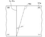
図15は、テスト軌跡Q1aと、テスト軌跡Q2aをと示す模式図である。図15に示すように、第一変形例では、摩擦攪拌接合を行う前に、一対の金属部材301,302を用いて修正移動ルートR2aを生成するためのテスト試行を行う。金属部材301,302は、実際に摩擦攪拌接合を行う第一金属部材101及び第二金属部材102と同じ、若しくは、近い材料、厚さ等であることが好ましい。つまり、第一金属部材101及び第二金属部材102による突合せ部J1と同様に、金属部材301,302同士を突き合わせて突合せ部J30を形成する。すなわち、このテスト試行では、第一金属部材101及び第二金属部材102と比して、同様の材種の金属からなり、同様の板厚寸法を有する板状部材を、同様の高さの段差を形成するようにして突き合わせた、表面の高さ位置が異なる二つの金属部材301,302を用いることが好ましい。 FIG. 15 is a schematic diagram showing a test trajectory Q1a and a test trajectory Q2a. As shown in FIG. 15, in the first modification, a test trial is performed to generate a modified movement route R2a using a pair ofmetal members 301 and 302 before performing friction stir welding. It is preferable that themetal members 301 and 302 have the same or similar material, thickness, etc., as thefirst metal member 101 and thesecond metal member 102 to which friction stir welding is actually performed. That is, similarly to the abutting part J1 formed by thefirst metal member 101 and thesecond metal member 102, the abutting part J30 is formed by abutting themetal members 301 and 302 against each other. That is, in this test trial, compared to thefirst metal member 101 and thesecond metal member 102, a plate-like member made of the same type of metal and having the same thickness dimension was It is preferable to use twometal members 301 and 302 having different surface height positions, which are butted against each other so as to form a .

テスト軌跡Q1aは、回転ツールFを金属部材301,302に挿入しないで、予め設定された設定移動ルートに従って、試験的に摩擦攪拌装置4を移動させた走行軌跡を示している。つまり、テスト軌跡Q1aは、無負荷状態で摩擦攪拌装置4のアームロボット31を移動させた走行軌跡である。このとき、回転ツールを金属部材301,302に挿入せずに無負荷の状態で移動させたものであれば、回転ツールFを取り付けずに移動させたものであってもよい。 The test trajectory Q1a shows a traveling trajectory in which thefriction stirrer 4 was experimentally moved according to a preset moving route without inserting the rotary tool F into themetal members 301, 302. In other words, the test trajectory Q1a is a travel trajectory in which thearm robot 31 of thefriction stirrer 4 is moved in a no-load state. At this time, as long as the rotary tool is moved without inserting it into themetal members 301, 302 and without a load, the rotary tool F may be moved without being attached.

一方、テスト軌跡Q2aは、回転ツールFを金属部材301,302に挿入して、予め設定されたテスト軌跡Q1aと同じ設定移動ルートに従って、試験的に摩擦攪拌を行った軌跡である。テスト軌跡Q1a及びテスト軌跡Q2aはいずれも金属部材301,302手前側から奥側に向けて回転ツールFを移動させた。テスト軌跡Q1aとテスト軌跡Q2aは、いずれも同じ設定移動ルートにしたがって移動させたにも関わらず、実際に摩擦攪拌を行うことで所定の角度の差分σ1が発生する。テスト軌跡Q1aとテスト軌跡Q2aは摩擦攪拌の始点の位置では一致しているものの、テスト軌跡Q2aは、無負荷の状態のテスト軌跡Q1aから、左側(薄板(第二金属部材302)側)へ角度σ1の差分をもって斜めに変位している。これにより、テスト軌跡Q1aとテスト軌跡Q2aとは、奥側の差分YLbが、中間付近側の差分YLaよりも大きくなっている。つまり、接合方向と直行する方向の差分YLは、回転ツールFが進行するにつれて徐々に大きくなるようになっている。 On the other hand, the test trajectory Q2a is a trajectory obtained by inserting the rotary tool F into themetal members 301, 302 and performing friction stirring on a trial basis according to the same set movement route as the preset test trajectory Q1a. In both the test trajectory Q1a and the test trajectory Q2a, the rotary tool F was moved from the front side of themetal members 301, 302 toward the back side. Even though the test trajectory Q1a and the test trajectory Q2a are both moved according to the same set movement route, a predetermined angular difference σ1 occurs when friction stirring is actually performed. Although the test trajectory Q1a and the test trajectory Q2a match at the starting point of friction stirring, the test trajectory Q2a is angled to the left (toward the thin plate (second metal member 302) side) from the test trajectory Q1a in the no-load state. It is displaced diagonally with a difference of σ1. As a result, between the test trajectory Q1a and the test trajectory Q2a, the difference YLb on the far side is larger than the difference YLa on the side near the middle. In other words, the difference YL in the direction perpendicular to the welding direction gradually increases as the rotary tool F advances.

このような回転ツールFのずれは、表面の高さ位置が異なるように突き合わされた二つの金属部材に回転ツールFが接触することで、アームロボット31に生じるたわみによって回転ツールFの位置がテスト軌跡Q1aからテスト軌跡Q2aに変位することに起因すると推察される。また、アームロボット31の癖、金属部材の材料抵抗等にも影響を受けていると推察される。 Such a deviation of the rotary tool F is caused by the position of the rotary tool F being tested due to the deflection that occurs in thearm robot 31 when the rotary tool F contacts two metal members that are butted against each other so that their surface heights are different. It is presumed that this is caused by the displacement from the trajectory Q1a to the test trajectory Q2a. It is also inferred that it is influenced by the habits of thearm robot 31, the material resistance of the metal members, etc.

したがって、摩擦攪拌接合でテスト軌跡Q2aを走行させたい場合は、差分σ1を考慮して設定移動ルートを設定する必要がある。差分σ1は、第一金属部材101及び第二金属部材102の摩擦攪拌接合前に、金属部材に回転ツールFを挿入した状態で摩擦攪拌接合を行ったテスト試行と、無負荷の状態で行ったテスト試行とを行い、これらに基づいて予め算出することができる。より詳しくは、差分σ1は、第一金属部材101及び第二金属部材102による突合せ部J1と同様に突合せ部を形成した金属部材に回転ツールFを挿入した状態で摩擦攪拌接合を行いながら回転ツールFを移動させた場合のテスト軌跡Q2aと、回転ツールFを金属部材に挿入せずに無負荷の状態で移動させた場合のテスト軌跡Q1aとの走行軌跡の角度の差分σ1から算出することができる。 Therefore, when it is desired to run the test trajectory Q2a in friction stir welding, it is necessary to set the set movement route in consideration of the difference σ1. The difference σ1 was determined between a test trial in which friction stir welding was performed with the rotary tool F inserted into the metal member before friction stir welding of thefirst metal member 101 and thesecond metal member 102, and a test trial in which friction stir welding was performed in a state with no load. It can be calculated in advance based on test trials. More specifically, the difference σ1 is calculated by inserting the rotary tool F into a metal member in which a butt part is formed in the same way as the butt part J1 between thefirst metal member 101 and thesecond metal member 102, and the rotary tool F is inserted while performing friction stir welding. It can be calculated from the difference σ1 in the angle of the running trajectory between the test trajectory Q2a when F is moved and the test trajectory Q1a when the rotary tool F is moved without inserting it into a metal member and without load. can.

なお、テスト軌跡Q1a及びテスト軌跡Q2aを得るための設定移動ルートは、突き合わせた金属部材の突合せ部J30付近をテスト軌跡Q2aが通過するように設定することが好ましい。特には、テスト軌跡Q2aの開始位置付近で突合せ部J30を通過して、突合せ部J30に沿って、厚板の金属部材側に向けて移動するように設定移動ルートを設定することが好ましい。なお、テスト試行を行う際は、金属部材301,302の少なくとも一方に回転ツールFを挿入してテスト軌跡Q1a,Q2aを取得すればよい。 Note that the travel route set for obtaining the test trajectory Q1a and the test trajectory Q2a is preferably set such that the test trajectory Q2a passes near the abutting portion J30 of the abutted metal members. In particular, it is preferable to set the set movement route so as to pass through the abutment J30 near the start position of the test trajectory Q2a and move along the abutment J30 toward the metal member side of the thick plate. In addition, when performing a test trial, the rotary tool F may be inserted into at least one of themetal members 301 and 302 to obtain the test trajectories Q1a and Q2a.

修正移動ルート生成部63では、図14に示すように、目標移動ルートR1a及び差分σ1に基づいて、修正移動ルートR2aを算出する。本変形例では、図15に示すように、回転ツールFを挿入した状態で摩擦攪拌接合を行ったテスト軌跡Q2aは、無負荷の状態のテスト軌跡Q1aから左側(薄板側)へ差分σ1だけ斜めに変位する傾向があるため、修正移動ルートR2aは、目標移動ルートR1aに対して右側(厚板(第一金属部材101)側)へ差分σ1だけ斜めに変位させた位置に設定する。言い換えれば、修正移動ルート生成部63は、ツールを挿入した状態での走行軌跡であるテスト軌跡Q2aが無負荷の状態での走行軌跡であるテスト軌跡Q1aに対して斜めに変位した角度σ1の分だけ、テスト軌跡Q2aが変位した向きとは反対方向に向けて、目標移動ルートR1aの進行方向(傾き)を斜めに変位させた位置に修正移動ルートR2aを設定する。つまり、修正移動ルートR2aは、回転ツールFの進行方向に向かうにつれて目標移動ルートR1aから徐々に離間するように設定する。摩擦攪拌制御部55は、修正移動ルートR2aで回転ツールFが移動するように制御することにより、差分σ1が吸収されて、目標移動ルートR1a上を回転ツールFが移動して、摩擦撹拌接合が行われるようになる。 As shown in FIG. 14, the corrected movementroute generation unit 63 calculates a corrected movement route R2a based on the target movement route R1a and the difference σ1. In this modification, as shown in FIG. 15, the test trajectory Q2a in which friction stir welding was performed with the rotating tool F inserted is diagonal by a difference σ1 to the left (thin plate side) from the test trajectory Q1a in the no-load state. Therefore, the corrected movement route R2a is set at a position that is obliquely displaced by a difference σ1 to the right side (thick plate (first metal member 101) side) with respect to the target movement route R1a. In other words, the corrected movementroute generation unit 63 generates an angle σ1 by which the test trajectory Q2a, which is the traveling trajectory with the tool inserted, is obliquely displaced with respect to the test trajectory Q1a, which is the traveling trajectory with no load. The corrected movement route R2a is set at a position where the traveling direction (inclination) of the target movement route R1a is obliquely displaced by the direction opposite to the direction in which the test trajectory Q2a is displaced. That is, the corrected movement route R2a is set so as to gradually move away from the target movement route R1a as the rotating tool F moves toward the direction of movement. The frictionstir control unit 55 controls the rotary tool F to move on the corrected movement route R2a, thereby absorbing the difference σ1, moving the rotary tool F on the target movement route R1a, and performing friction stir welding. will be carried out.

第一変形例において、修正移動ルート生成部63は、判定部64によって摩擦攪拌接合中の回転ツールFの位置が許容範囲M外と判定された場合、摩擦攪拌接合中の回転ツールFの位置に応じて回転ツールFの位置を再設定した修正移動ルートR2aを算出することが好ましい。具体的には、摩擦攪拌接合中の回転ツールFのY方向の位置が第一金属部材101側となっていた箇所では、この箇所の回転ツールFの位置が第二金属部材102側となるように修正移動ルートR2aを再設定する。同様に、摩擦攪拌接合中の回転ツールFのY方向の位置が第二金属部材102側となっていた箇所では、この箇所の回転ツールFの位置が第一金属部材101側となるように修正移動ルートR2aを再設定する。 In the first modification, when thedetermination unit 64 determines that the position of the rotary tool F during friction stir welding is outside the allowable range M, the modified movementroute generation unit 63 changes the position of the rotary tool F during friction stir welding to the position of the rotary tool F during friction stir welding. It is preferable to calculate a corrected movement route R2a in which the position of the rotary tool F is reset accordingly. Specifically, in a place where the position of the rotary tool F in the Y direction during friction stir welding was on thefirst metal member 101 side, the position of the rotary tool F at this place is on thesecond metal member 102 side. The corrected movement route R2a is reset. Similarly, in a location where the position of the rotary tool F in the Y direction during friction stir welding was on thesecond metal member 102 side, the position of the rotary tool F at this location is corrected so that it is on thefirst metal member 101 side. Reset the travel route R2a.

また、判定部64は、摩擦攪拌接合中の回転ツールFの位置が許容範囲M外と判定された場合、その第一金属部材101及び第二金属部材102をワーク番号と関連付けて数値範囲外品と判定してもよい。 Further, when it is determined that the position of the rotary tool F during friction stir welding is outside the allowable range M, thedetermination unit 64 associates thefirst metal member 101 and thesecond metal member 102 with the workpiece number to produce a product that is outside the numerical range. It may be determined that

なお、テスト軌跡Q1a及びテスト軌跡Q2aの差分σ1が小さい又は無い場合は、修正移動ルートは設定せずに、目標移動ルートR1aに基づいて回転ツールFを移動させてもよい。また、差分σ1の取得(算出)は摩擦攪拌接合ごとに行う必要はないが、例えば、回転ツールFを交換する場合、第一金属部材101及び第二金属部材102の板厚寸法、材種、表面の高さ位置等を変更する場合に応じて取得し、差分σ1と修正移動ルートR2aを算出することが好ましい。 Note that if the difference σ1 between the test trajectory Q1a and the test trajectory Q2a is small or absent, the rotary tool F may be moved based on the target movement route R1a without setting the corrected movement route. Although it is not necessary to obtain (calculate) the difference σ1 for each friction stir welding, for example, when replacing the rotary tool F, the plate thickness dimension, material type, It is preferable to obtain the difference σ1 and the corrected movement route R2a according to the case where the height position of the surface, etc. is changed.

[C-2.動作フロー]
本変形例に係る自動接合システム1は、図13を参照して説明した第一実施形態に係る自動接合システムの動作フローと同様に動作を行うことができる。
[C-2. Operation flow]
The automatic joiningsystem 1 according to this modification can operate in the same manner as the operational flow of the automatic joining system according to the first embodiment described with reference to FIG. 13.

本変形例に係る自動接合システム1では、ステップST5において、摩擦攪拌制御部55(修正移動ルート生成部63)は、稜線位置Yp及び予め取得した差分σ1に基づいて修正移動ルートR2aを生成する。具体的には、稜線位置Ypを目標移動ルートR1aとして算出するとともに、目標移動ルートR1aに対して斜めに差分σ1だけ変位させた位置に修正移動ルートR2aを設定する。 In the automatic joiningsystem 1 according to this modification, in step ST5, the friction stir control unit 55 (corrected movement route generation unit 63) generates a corrected movement route R2a based on the ridgeline position Yp and the difference σ1 acquired in advance. Specifically, the ridgeline position Yp is calculated as the target movement route R1a, and the corrected movement route R2a is set at a position diagonally displaced by a difference σ1 with respect to the target movement route R1a.

ステップST5における、修正移動ルート生成部63による修正移動ルートR2aの生成に先立って、差分σ1を取得しておくことが好ましい。差分σ1の取得は、まず、目標移動ルート生成部61が目標移動ルートR1aを設定し、設定移動ルート生成部65が設定移動ルートを生成する。次に、生成された設定移動ルートに従って、金属部材301,302に回転ツールFを挿入しないで無負荷の状態で移動させたテスト軌跡Q1aと、金属部材301,302に回転ツールFを挿入して摩擦攪拌接合を行いながら移動させたテスト軌跡Q2aとをそれぞれ得る。そして、テスト軌跡Q1aとテスト軌跡Q2aとの差分から、差分σ1を取得する。差分σ1の取得は、ステップST5よりも前のタイミングで行えばよいが、第一金属部材101及び第二金属部材102をセットするステップST1よりも前に予め行っておくことが好ましい。 It is preferable to obtain the difference σ1 before the modified travelroute generation unit 63 generates the modified travel route R2a in step ST5. To obtain the difference σ1, first, the target movementroute generation unit 61 sets the target movement route R1a, and the set movementroute generation unit 65 generates the set movement route. Next, according to the generated set movement route, a test trajectory Q1a is obtained by moving the rotary tool F into themetal members 301 and 302 without inserting the rotary tool F in an unloaded state, and a test trajectory Q1a in which the rotary tool F is inserted into themetal members 301 and 302. A test trajectory Q2a is obtained by moving while performing friction stir welding. Then, a difference σ1 is obtained from the difference between the test trajectory Q1a and the test trajectory Q2a. Although the difference σ1 may be obtained at a timing before step ST5, it is preferable to obtain the difference σ1 before step ST1 in which thefirst metal member 101 and thesecond metal member 102 are set.

[C-3.作用効果]
回転ツールFを挿入した状態で所定の移動ルートに沿って移動するように制御して摩擦攪拌接合を行いながら移動させると、回転ツールFの走行軌跡が移動ルートからずれしまい、ルートフローが生じるなどして接合品質が低下するおそれがある。例えば、図6に示すように、アームロボット31を備える摩擦攪拌装置4によって、第一金属部材101及び第二金属部材102との突合せ部J1に対して平行な移動ルートを通過して摩擦攪拌接合しようとした場合には、突合せ部J1から回転ツールFの走行軌跡が斜めに変位して、回転ツールFの位置が進行方向に進むにつれてずれが広がってしまうことがあった。
[C-3. Effect】
If the rotating tool F is inserted and controlled to move along a predetermined moving route while performing friction stir welding, the running trajectory of the rotating tool F will deviate from the moving route, causing route flow, etc. There is a risk that the bonding quality will deteriorate. For example, as shown in FIG. 6, the friction stir welding is performed by afriction stir device 4 equipped with anarm robot 31 passing through a movement route parallel to the abutting portion J1 of thefirst metal member 101 and thesecond metal member 102. In this case, the travel locus of the rotary tool F may be obliquely displaced from the abutting portion J1, and the deviation may become wider as the position of the rotary tool F advances in the traveling direction.

本発明者らの検討により、突合せ部J1の摩擦撹拌接合を行う際に回転ツールFが実際に移動する走行軌跡は、回転ツールFの移動が制御される位置の軌跡に対して、斜めに変位しているケースが見いだされた。このような斜めの変位は、主として、摩擦攪拌装置4のアームロボット31の姿勢に起因して生じると考えられる。すなわち、金属部材101,102の突合せ部J1上での接合に伴って接合方向に向けて回転ツールFが進むにつれて、先端に回転ツールFが取り付けられたアームロボット31の姿勢が変化する。例えば、アームロボット31が多関節のアーム31aを備える場合、多関節のアーム31aを伸ばし広げるようにして摩擦攪拌装置4の本体から遠い位置を接合する場合と、多関節のアーム31aを折り縮めるようにして摩擦攪拌装置4の本体から近い位置を接合する場合とでは、その姿勢は異なることになる。走行位置によってアームロボット31の姿勢が変化すると、アームロボット31が力を受ける方向が変わり、アームロボット31のばね定数が変化することになる。回転ツールFを金属部材101,102に挿入することでアームロボット31にたわみが生じることになるが、回転ツールFの走行位置によってアームロボット31のばね定数が変化することで、アームロボット31のたわみ量が変化することになる。回転ツールFを所定の移動ルートに沿って移動するように制御して移動させた場合には、回転ツールFが移動するにつれてアームロボット31のたわみ量が大きくなり、回転ツールFの走行軌跡が所定の移動ルートからずれていくことになる。このようにして、斜めの変位が生じると考えられる。 The inventors' studies have revealed that the travel locus that the rotary tool F actually moves when performing friction stir welding of the butt portion J1 is obliquely displaced with respect to the locus of the position where the movement of the rotary tool F is controlled. A case was found where this was the case. It is thought that such oblique displacement occurs mainly due to the posture of thearm robot 31 of thefriction stirrer 4. That is, as the rotary tool F advances in the welding direction as themetal members 101 and 102 are joined on the abutting portion J1, the posture of thearm robot 31 having the rotary tool F attached to its tip changes. For example, when thearm robot 31 is equipped with amulti-joint arm 31a, there is a case where themulti-joint arm 31a is extended and spread to connect a position far from the main body of thefriction stirrer 4, and a case where themulti-joint arm 31a is folded and contracted. The posture will be different when joining a position close to the main body of thefriction stirrer 4. When the posture of thearm robot 31 changes depending on the traveling position, the direction in which thearm robot 31 receives force changes, and the spring constant of thearm robot 31 changes. Inserting the rotary tool F into themetal members 101 and 102 will cause thearm robot 31 to bend, but since the spring constant of thearm robot 31 changes depending on the traveling position of the rotary tool F, thearm robot 31 will bend. The amount will change. When the rotary tool F is controlled and moved so that it moves along a predetermined movement route, the amount of deflection of thearm robot 31 increases as the rotary tool F moves, and the travel trajectory of the rotary tool F is moved along a predetermined movement route. This will cause them to deviate from their travel route. In this way, it is believed that a diagonal displacement occurs.

本変形例に係る自動接合システム1によれば、摩擦攪拌接合を行う前に測定した第一金属部材101の稜線位置Ypに基づいて回転ツールFの目標移動ルートR1aを設定するとともに、目標移動ルートR1aに対して斜めに変位させた位置に修正移動ルートR2aを設定する。そして、回転ツールFを修正移動ルートR2aに沿って移動するように制御することで、回転ツールFを目標移動ルートR1aに沿って摩擦攪拌接合を行うことができるようになった。このように、セットされた第一金属部材101ごとの稜線位置Ypに基づいて、突合せ部J1の摩擦撹拌接合を行う際に生じる変位を補償した位置に回転ツールFを移動するように制御することで、回転ツールFの変位を抑えた的確な移動ルートを容易に設定することができる。これにより接合品質を高めることができる。特には、本変形例では、ツールを挿入した状態での走行軌跡であるテスト軌跡Q2aと、無負荷の状態での走行軌跡であるテスト軌跡Q1aとの差分σ1の角度に基づいて、目標移動ルートR1aの進行方向(傾き)を斜めに変位させた位置に修正移動ルートR2aを設定する。これにより、金属部材101,102を接合するための摩擦攪拌装置4のアームロボット31の姿勢に応じて生じる、回転ツールFの走行軌跡の斜めの変位を抑えた移動ルートを設定して、接合品質を高めることができる。 According to theautomatic welding system 1 according to the present modification, the target movement route R1a of the rotary tool F is set based on the ridge line position Yp of thefirst metal member 101 measured before performing friction stir welding, and the target movement route A corrected movement route R2a is set at a position obliquely displaced with respect to R1a. By controlling the rotary tool F to move along the corrected movement route R2a, it became possible to perform friction stir welding using the rotary tool F along the target movement route R1a. In this way, based on the ridge line position Yp of each setfirst metal member 101, the rotary tool F is controlled to be moved to a position that compensates for the displacement that occurs when performing friction stir welding of the abutting portion J1. Therefore, it is possible to easily set an accurate movement route that suppresses displacement of the rotary tool F. This makes it possible to improve bonding quality. In particular, in this modification, the target movement route is determined based on the angle of the difference σ1 between the test trajectory Q2a, which is the trajectory with the tool inserted, and the test trajectory Q1a, which is the trajectory with no load. A corrected movement route R2a is set at a position where the traveling direction (inclination) of R1a is obliquely displaced. As a result, it is possible to set a movement route that suppresses the diagonal displacement of the running trajectory of the rotary tool F, which occurs depending on the posture of thearm robot 31 of thefriction stir device 4 for joining themetal members 101 and 102, thereby improving the joining quality. can be increased.

[D.第二変形例]
次に、前記した第一実施形態の第二変形例について説明する。前記した実施形態では、摩擦攪拌接合を行う前に段差寸法hを測定したが、段差寸法hに換えて又は段差寸法hに加えて第一厚さ寸法t11及び第二厚さ寸法t12(図12参照)を測定してもよい。
[D. Second modification]
Next, a second modification of the first embodiment described above will be described. In the embodiment described above, the step dimension h was measured before performing friction stir welding, but instead of or in addition to the step dimension h, the first thickness dimension t11 and the second thickness dimension t12 (FIG. 12 ) may also be measured.

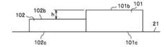
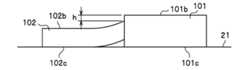
図12に示すように、第一厚さ寸法t11は、架台21の表面から第一金属部材101の表面101bまでの距離(高さ寸法)を言う。第二厚さ寸法t12は、架台21の表面から第二金属部材102の表面102bまでの距離(高さ寸法)を言う。 As shown in FIG. 12, the first thickness dimension t11 refers to the distance (height dimension) from the surface of thepedestal 21 to thesurface 101b of thefirst metal member 101. The second thickness dimension t12 refers to the distance (height dimension) from the surface of thepedestal 21 to thesurface 102b of thesecond metal member 102.

第一厚さ寸法t11及び第二厚さ寸法t12は、例えば、測定部34で測定することができる。つまり、摩擦攪拌接合を行う前に、突合せ部J1に沿って測定部34を移動させることにより、第一厚さ寸法t11及び第二厚さ寸法t12を得ることができる。このとき、突合せ部J1に加え、架台21の表面の高さ位置を測定することができるように測定部34を移動させることで、架台21の表面から第一金属部材101の表面101b及び第二金属部材102の表面102bまでの距離を計測することができる。 The first thickness dimension t11 and the second thickness dimension t12 can be measured by themeasurement unit 34, for example. That is, before friction stir welding is performed, the first thickness dimension t11 and the second thickness dimension t12 can be obtained by moving the measuringsection 34 along the abutting section J1. At this time, in addition to the abutting part J1, by moving themeasurement part 34 so that the height position of the surface of thepedestal 21 can be measured, thesurface 101b of thefirst metal member 101 and the second The distance to thesurface 102b of themetal member 102 can be measured.

第二変形例では、判定部64は、摩擦攪拌接合を行う前又は摩擦攪拌接合中において測定部34から送信された結果(第一厚さ寸法t11及び第二厚さ寸法t12)が、所定の数値範囲内か否かを判定する。判定部64は、第一厚さ寸法t11及び第二厚さ寸法t12が所定の数値範囲外と判定した場合、その第一金属部材101及び第二金属部材102をワーク番号と関連付けて数値範囲外品と判定する。判定部64は、当該判定結果を主制御部41に送信するとともに記憶部44に格納する。当該判定結果は、表示部43に表示させるようにしてもよいし、判定結果に応じて音や光などを出力する報知手段で報知するようにしてもよい。 In the second modification, thedetermination unit 64 determines whether the results (first thickness dimension t11 and second thickness dimension t12) transmitted from themeasurement unit 34 before or during friction stir welding are within a predetermined value. Determine whether the value is within the numerical range. When thedetermination unit 64 determines that the first thickness dimension t11 and the second thickness dimension t12 are outside the predetermined numerical range, thedetermination unit 64 associates thefirst metal member 101 and thesecond metal member 102 with the workpiece number and determines that the first thickness dimension t11 and the second thickness dimension t12 are outside the numerical range. It is determined that the product is of good quality. Thedetermination section 64 transmits the determination result to themain control section 41 and stores it in thestorage section 44 . The determination result may be displayed on thedisplay unit 43, or may be notified by a notification means that outputs sound, light, etc. according to the determination result.

また、摩擦攪拌接合を行う前又は摩擦攪拌接合中において第一厚さ寸法t11及び第二厚さ寸法t12が所定の数値範囲外と判定された場合、クランプ部24は、直ちに第一金属部材101及び第二金属部材102の固定を解除する制御を行ってもよい。この場合、例えば、搬送装置2のアームロボット11で第一金属部材101及び第二金属部材102の位置を微修正(再セット)するようにしてもよいし、当該第一金属部材101及び第二金属部材102を架台21から取り出して、新たな第一金属部材101及び第二金属部材102を配置するようにしてもよい。 Further, if it is determined that the first thickness dimension t11 and the second thickness dimension t12 are outside the predetermined numerical range before or during friction stir welding, theclamp part 24 immediately Control may also be performed to release the fixation of thesecond metal member 102. In this case, for example, thearm robot 11 of thetransfer device 2 may slightly correct (reset) the positions of thefirst metal member 101 and thesecond metal member 102, or thefirst metal member 101 and thesecond metal member 102 may be Themetal member 102 may be taken out from thepedestal 21 and a newfirst metal member 101 andsecond metal member 102 may be placed.

ここで、摩擦攪拌接合の際、第一金属部材101及び第二金属部材102の板厚は接合品質に大きな影響を与える。第一金属部材101及び第二金属部材102の板厚の組み合わせによっては、回転ツールFをどのように制御しても接合不良となる場合もある。また、例えば、海外で部材を調達する場合は、第一金属部材101及び第二金属部材102の板厚のばらつきが大きくなる傾向がある。 Here, during friction stir welding, the plate thicknesses of thefirst metal member 101 and thesecond metal member 102 have a large effect on the welding quality. Depending on the combination of the plate thicknesses of thefirst metal member 101 and thesecond metal member 102, poor joining may occur no matter how the rotary tool F is controlled. Further, for example, when parts are procured overseas, variations in the thickness of thefirst metal member 101 and thesecond metal member 102 tend to increase.

この点、第二変形例のように、摩擦攪拌接合を行う前又は摩擦攪拌接合中において第一厚さ寸法t11及び第二厚さ寸法t12を測定しつつ、これらの測定結果が所定の数値範囲か否かを判定することにより、品質管理の精度をより高めることができる。 In this respect, as in the second modification, the first thickness dimension t11 and the second thickness dimension t12 are measured before or during friction stir welding, and these measurement results are within a predetermined numerical range. By determining whether this is the case, the accuracy of quality control can be further improved.

また、第二変形例の制御装置5は、第一厚さ寸法t11及び第二厚さ寸法t12が所定の数値範囲外と判定した場合、回転ツールFの狙い角、前進角、挿入量及び回転ツールFの位置の少なくとも一つを予め設定されていた条件から変更するように制御してもよい。第一厚さ寸法t11及び第二厚さ寸法t12に対する回転ツールFの狙い角、前進角、挿入量及び回転ツールFの位置については、厚さの異なる第一金属部材101及び第二金属部材102を複数準備して事前に行った試験から最適又は最適に近い条件を用意することができる。このような第二変形例によれば、第一厚さ寸法t11及び第二厚さ寸法t12に応じて、最適又は最適に近い条件で摩擦攪拌接合を行うことができるため、安定した接合品質維持することができる。 In addition, when thecontrol device 5 of the second modification determines that the first thickness dimension t11 and the second thickness dimension t12 are outside the predetermined numerical range, thecontrol device 5 controls the aim angle, advance angle, insertion amount, and rotation of the rotary tool F. Control may be performed to change at least one position of the tool F from a preset condition. Regarding the aiming angle, advance angle, insertion amount, and position of the rotary tool F with respect to the first thickness dimension t11 and the second thickness dimension t12, thefirst metal member 101 and thesecond metal member 102 having different thicknesses Optimal or near-optimal conditions can be prepared from tests conducted in advance by preparing multiple conditions. According to such a second modification, friction stir welding can be performed under optimal or near-optimal conditions depending on the first thickness dimension t11 and the second thickness dimension t12, so stable welding quality can be maintained. can do.

なお、前進角とは、進行方向に対して回転ツールFを側方から見た場合、鉛直軸に対する回転ツールFの回転中心軸Uの角度を言う。挿入量とは、第一金属部材101の表面101bから先端側ピンF3の平坦面の中心F5(図12参照)までの距離を言う。 Note that the forward angle refers to the angle of the rotation center axis U of the rotary tool F with respect to the vertical axis when the rotary tool F is viewed from the side with respect to the advancing direction. The insertion amount refers to the distance from thesurface 101b of thefirst metal member 101 to the center F5 (see FIG. 12) of the flat surface of the tip end pin F3.

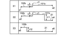
ここで、第一厚さ寸法t11及び第二厚さ寸法t12の測定は、摩擦攪拌接合を行う前に、段差寸法h等の測定とは別に測定してもよい。測定部は、例えば、ラインセンサ(レーザー変位計)を用いることができる。図17に示すように、板厚の大きい第一金属部材101と、板厚の小さい第二金属部材102とを突き合わせて突合せ部J1を形成する場合、当該測定部をルートE1、ルートE2及びルートE3と位置を変えて複数回(ここでは3回)移動させることで摩擦攪拌接合前の第一厚さ寸法t11及び第二厚さ寸法t12を測定することができる。 Here, the first thickness dimension t11 and the second thickness dimension t12 may be measured separately from the measurement of the step dimension h and the like before performing friction stir welding. For example, a line sensor (laser displacement meter) can be used as the measurement unit. As shown in FIG. 17, when afirst metal member 101 with a large plate thickness and asecond metal member 102 with a small plate thickness are butted against each other to form a butt portion J1, the measurement portion is connected to the root E1, the root E2, and the root The first thickness dimension t11 and the second thickness dimension t12 before friction stir welding can be measured by changing the position with E3 and moving it multiple times (here, three times).

図16に示すように、ルートE1は、第二金属部材102の表面102bの点e1から第一金属部材101の表面101bの点e2まで突合せ部J1に対して斜めに測定部を移動させる。つまり、測定部は第二金属部材102の表面102b、突合せ部J1及び第一金属部材101の表面101bを通過する。これにより、図17の上段に示すように、段差寸法hを測定することができる。 As shown in FIG. 16, the route E1 moves the measuring section obliquely with respect to the abutting portion J1 from a point e1 on thesurface 102b of thesecond metal member 102 to a point e2 on thesurface 101b of thefirst metal member 101. That is, the measuring section passes through thesurface 102b of thesecond metal member 102, the abutting portion J1, and thesurface 101b of thefirst metal member 101. Thereby, as shown in the upper part of FIG. 17, the step dimension h can be measured.

また、ルートE2は、第二金属部材102の表面102bの点e3から架台21の表面の点e4まで突合せ部J1に対して斜めに測定部を移動させる。ルートE2とルートE1とは平行になっている。つまり、測定部は第二金属部材102の表面102b、突合せ部J1、第一金属部材101の表面101b及び架台21を通過する。これにより、図17の中段に示すように、段差寸法h及び架台21の表面から第一金属部材101の表面101bまでの距離(第一厚さ寸法t11)を測定することができる。 In addition, the route E2 moves the measuring section obliquely with respect to the abutting section J1 from the point e3 on thesurface 102b of thesecond metal member 102 to the point e4 on the surface of thepedestal 21. Route E2 and route E1 are parallel. In other words, the measuring section passes through thesurface 102b of thesecond metal member 102, the abutting portion J1, thesurface 101b of thefirst metal member 101, and thepedestal 21. Thereby, as shown in the middle part of FIG. 17, the step dimension h and the distance from the surface of thepedestal 21 to thesurface 101b of the first metal member 101 (first thickness dimension t11) can be measured.

また、ルートE3は、第二金属部材102の表面102bの点e5から架台21の表面の点e6まで突合せ部J1に対して斜めに測定部を移動させる。ルートE3とルートE2とは平行になっている。つまり、測定部は第二金属部材102の表面102b及び架台21を通過する。これにより、図17の下段に示すように、架台21の表面から第二金属部材102の表面102bまでの距離(第二厚さ寸法t12)を測定することができる。 In addition, the route E3 moves the measuring section obliquely with respect to the abutting section J1 from the point e5 on thesurface 102b of thesecond metal member 102 to the point e6 on the surface of thepedestal 21. Route E3 and route E2 are parallel. That is, the measuring section passes through thesurface 102b of thesecond metal member 102 and thepedestal 21. Thereby, as shown in the lower part of FIG. 17, the distance (second thickness dimension t12) from the surface of thepedestal 21 to thesurface 102b of thesecond metal member 102 can be measured.

以上のようにして第一厚さ寸法t11及び第二厚さ寸法t12を測定してもよい。また、第一厚さ寸法t11及び第二厚さ寸法t12は他の方法、他の器具で測定してもよい。 The first thickness dimension t11 and the second thickness dimension t12 may be measured as described above. Moreover, the first thickness dimension t11 and the second thickness dimension t12 may be measured by other methods or other instruments.

[E.第二実施形態]
次に、本発明の第二実施形態について説明する。第二実施形態では、修正移動ルートの算出方法が前記した第一実施形態と相違する。第二実施形態では、第一実施形態と相違する部分を中心に説明する。前記した第一実施形態では、回転ツールFを挿入した状態で移動させた走行軌跡と、回転ツールFを無負荷の状態で移動させた走行軌跡との差分に基づいて、目標移動ルートR1を変位させた位置に修正移動ルートR2を設定した。第二実施形態では、回転ツールFを挿入した状態で移動させた走行軌跡と、目標移動ルートとの差分に基づいて、設定移動ルートP1bを変位させた位置に修正移動ルートR2bを設定する。第二実施形態において、設定移動ルートP1bを略平行に変位させた位置に修正移動ルートR2bを設定する手法は、上記の第一実施形態で説明した差分YLに基づく修正移動ルートR2の設定と同様に行うことができる。また、第二実施形態において、設定移動ルートP1bを斜めに変位させた位置に修正移動ルートR2bを設定する手法は、上記の第一実施形態の第一変形例で説明した差分σ1に基づく修正移動ルートR2aの設定と同様に行うことができる。
[E. Second embodiment]
Next, a second embodiment of the present invention will be described. The second embodiment is different from the first embodiment described above in the method of calculating the corrected movement route. The second embodiment will be mainly described with respect to parts that are different from the first embodiment. In the first embodiment described above, the target movement route R1 is displaced based on the difference between the travel trajectory traveled with the rotary tool F inserted and the travel trajectory traveled with the rotary tool F moved with no load. A corrected movement route R2 was set at the position. In the second embodiment, a corrected movement route R2b is set at a position to which the set movement route P1b is displaced based on the difference between the travel trajectory moved with the rotary tool F inserted and the target movement route. In the second embodiment, the method of setting the corrected moving route R2b at a position where the set moving route P1b is displaced approximately parallel to the set moving route P1b is the same as the setting of the corrected moving route R2 based on the difference YL described in the first embodiment. can be done. In addition, in the second embodiment, the method of setting the corrected movement route R2b at a position where the set movement route P1b is obliquely displaced is based on the corrected movement route R2b based on the difference σ1 explained in the first modification of the first embodiment above. This can be done in the same way as setting route R2a.

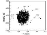
図18は、第二実施形態に係る修正移動ルートの算出方法を説明するための模式平面図である。図18では、目標移動ルートR1bと、設定移動ルートP1bと、テスト軌跡Q2bと、修正移動ルートR2bとを示している。第二実施形態に係る修正移動ルートの算出方法では、一対の金属部材301,302を用いて修正移動ルートR2bを生成するためのテスト試行を行う。金属部材301,302は、実際に摩擦攪拌接合を行う第一金属部材101及び第二金属部材102と同じ、若しくは、近い材料、厚さ等であることが好ましい。つまり、第一金属部材101及び第二金属部材102による突合せ部J1と同様に、金属部材301,302同士を突き合わせて突合せ部J30を形成する。すなわち、このテスト試行では、第一金属部材101及び第二金属部材102と比して、同様の材種の金属からなり、同様の板厚寸法を有する板状部材を、同様の高さの段差を形成するようにして突き合わせた、表面の高さ位置が異なる二つの金属部材301,302を用いることが好ましい。 FIG. 18 is a schematic plan view for explaining a method of calculating a corrected movement route according to the second embodiment. FIG. 18 shows a target movement route R1b, a set movement route P1b, a test trajectory Q2b, and a modified movement route R2b. In the method for calculating a corrected movement route according to the second embodiment, a test trial is performed using a pair ofmetal members 301 and 302 to generate a corrected movement route R2b. It is preferable that themetal members 301 and 302 have the same or similar material, thickness, etc., as thefirst metal member 101 and thesecond metal member 102 to which friction stir welding is actually performed. That is, similarly to the abutting part J1 formed by thefirst metal member 101 and thesecond metal member 102, the abutting part J30 is formed by abutting themetal members 301 and 302 against each other. That is, in this test trial, compared to thefirst metal member 101 and thesecond metal member 102, a plate-like member made of the same type of metal and having the same thickness dimension was It is preferable to use twometal members 301 and 302 having different surface height positions, which are butted against each other so as to form a .

目標移動ルートR1bは、第一実施形態で説明した目標移動ルートR1と同様に、突合せ部J1の摩擦攪拌接合を行う際に、回転ツールFが移動する目標となる軌跡を設定するものである。 Similar to the target movement route R1 described in the first embodiment, the target movement route R1b is used to set a target trajectory along which the rotary tool F moves when performing friction stir welding of the butt portion J1.

設定移動ルートP1bは、第一実施形態で説明した設定移動ルート生成部65と同様に、回転ツールFを移動させるための指示位置となるものである。設定移動ルートP1bは、回転ツールFの軌跡の変位を利用して、修正移動ルートR2bを生成するために用いられる。 The set movement route P1b is a designated position for moving the rotary tool F, similar to the set movementroute generation unit 65 described in the first embodiment. The set movement route P1b is used to generate a modified movement route R2b using the displacement of the locus of the rotary tool F.

テスト軌跡Q2bは、回転ツールFを金属部材301,302に挿入して、回転ツールFを設定移動ルートP1bに沿って移動するように制御して摩擦攪拌接合を行いながら移動させた走行軌跡である。 The test trajectory Q2b is a travel trajectory in which the rotary tool F is inserted into themetal members 301 and 302, and is moved while performing friction stir welding by controlling the rotary tool F to move along the set movement route P1b. .

修正移動ルートR2bは、第一実施形態で説明した修正移動ルートR2と同様に、回転ツールFを移動させるための指示位置となるものである。特には、修正移動ルートR2bは、突合せ部J1の摩擦攪拌接合を行う際に、回転ツールFがこのルートに沿って移動するように制御される軌跡を示す。回転ツールFを修正移動ルートR2bに沿って移動するように制御することで、回転ツールFは目標移動ルートR1bに沿って移動するように摩擦攪拌接合が行われる。また、後述するように、修正移動ルートR2bは、テスト軌跡Q2b及び目標移動ルートR1bを利用して設定される。 The corrected movement route R2b is a designated position for moving the rotary tool F, similar to the corrected movement route R2 described in the first embodiment. In particular, the corrected movement route R2b indicates a trajectory along which the rotary tool F is controlled to move when performing friction stir welding of the butt portion J1. By controlling the rotary tool F to move along the corrected movement route R2b, friction stir welding is performed so that the rotary tool F moves along the target movement route R1b. Furthermore, as will be described later, the corrected movement route R2b is set using the test trajectory Q2b and the target movement route R1b.

第二実施形態に係る修正移動ルートの算出方法では、まず、目標移動ルート生成部61が、目標移動ルートR1bを設定する。目標移動ルートR1bは、回転ツールFを実際に移動させたいルートである。目標移動ルートR1bは、本変形例では第一金属部材301の表面に突合せ部J30と平行に設定する。 In the method for calculating a corrected movement route according to the second embodiment, first, the target movementroute generation unit 61 sets a target movement route R1b. The target movement route R1b is the route on which the rotary tool F is actually desired to be moved. In this modification, the target movement route R1b is set on the surface of thefirst metal member 301 in parallel to the abutting portion J30.

次に、設定移動ルート生成部65が、目標移動ルートR1bから平行に変位させた位置に設定移動ルートP1bを設定する。設定移動ルートP1bは、摩擦攪拌装置4に入力して定まる仮想の移動ルートである。設定移動ルートP1bは、目標移動ルートR1bに対して突合せ部J30とは反対側に設定されている。 Next, the set movementroute generation unit 65 sets the set movement route P1b at a position displaced in parallel from the target movement route R1b. The set movement route P1b is a virtual movement route determined by inputting it into thefriction stirrer 4. The set movement route P1b is set on the opposite side of the target movement route R1b from the abutting portion J30.

次に、設定移動ルートP1bに沿って回転ツールFを移動させてテスト軌跡(走行軌跡)Q2bを取得する。テスト軌跡Q2bは、測定データに基づく近似直線として得ることができる。ここでは、回転ツールFを第一金属部材301の表面に挿入し、設定移動ルートP1bに沿って回転ツールFを移動させる。このとき、前記したように、突合せ部J30に沿って回転ツールFを移動させると、第一金属部材301及び第二金属部材302と回転ツールFとが接触することで、アームロボット31の姿勢に応じて回転ツールFの走行軌跡が斜めに変位する。また、金属部材302の板厚が、金属部材301の板厚よりも薄いため、回転ツールFの走行軌跡が、薄板側(金属部材302)へ略平行に変位する。これにより、回転ツールFを進行させるにつれて、テスト軌跡Q2bと目標移動ルートR1bとは、傾きと距離において差分が生じる。 Next, the rotary tool F is moved along the set movement route P1b to obtain a test trajectory (traveling trajectory) Q2b. The test trajectory Q2b can be obtained as an approximate straight line based on measurement data. Here, the rotary tool F is inserted into the surface of thefirst metal member 301, and the rotary tool F is moved along the set movement route P1b. At this time, as described above, when the rotary tool F is moved along the abutting portion J30, thefirst metal member 301 and thesecond metal member 302 come into contact with the rotary tool F, thereby changing the posture of thearm robot 31. Correspondingly, the traveling locus of the rotary tool F is displaced obliquely. Further, since the thickness of themetal member 302 is thinner than that of themetal member 301, the traveling locus of the rotary tool F is displaced approximately parallel to the thin plate side (metal member 302). As a result, as the rotary tool F advances, a difference occurs between the test trajectory Q2b and the target movement route R1b in terms of inclination and distance.

そこで、修正移動ルート生成部63は、このようなテスト軌跡Q2bと目標移動ルートR1bとの差分に基づいて、修正移動ルートR2bを設定する。具体的には、修正移動ルート生成部63は、ツールを挿入した状態での走行軌跡であるテスト軌跡Q2bが目標移動ルートR1bに対して斜めに変位した角度の分だけ、テスト軌跡Q2bが変位した向きとは反対方向に向けて、設定移動ルートP1bの進行方向(傾き)を斜めに変位させるとともに、ツールを挿入した状態での走行軌跡であるテスト軌跡Q2bが目標移動ルートR1bに対して略平行に変位した長さの分だけ、テスト軌跡Q2bが変位した向きとは反対方向に向けて、設定移動ルートP1bを略平行に変位させた位置に修正移動ルートR2bを設定する。 Therefore, the corrected movementroute generation unit 63 sets a corrected movement route R2b based on the difference between the test trajectory Q2b and the target movement route R1b. Specifically, the corrected movementroute generation unit 63 determines that the test trajectory Q2b is displaced by the angle at which the test trajectory Q2b, which is the travel trajectory with the tool inserted, is obliquely displaced with respect to the target movement route R1b. The traveling direction (inclination) of the set movement route P1b is obliquely displaced in the opposite direction, and the test trajectory Q2b, which is the travel trajectory with the tool inserted, is approximately parallel to the target movement route R1b. A corrected movement route R2b is set at a position where the set movement route P1b is displaced substantially parallel to the direction in which the test trajectory Q2b is displaced by the length of the displacement.

修正移動ルートR2bに沿って回転ツールFを移動させることにより、回転ツールFが目標移動ルートR1b上を移動するようになる。 By moving the rotation tool F along the corrected movement route R2b, the rotation tool F is moved on the target movement route R1b.

このように第二実施形態では、修正移動ルートR2bを設定することができる。摩擦攪拌制御部55は、修正移動ルートR2bで回転ツールFが移動するように制御することにより、差分が吸収されて、目標移動ルートR1b上を回転ツールFが移動して、摩擦撹拌接合が行われるようになる。すなわち、本実施形態では、回転ツールFを挿入した状態での走行軌跡であるテスト軌跡Q2bと、目標移動ルートR1bとの差分の角度に基づいて、設定移動ルートP1bの進行方向(傾き)を斜めに変位させた位置に修正移動ルートR2bを設定する。これにより、第一実施形態の第一変形例と同様に、金属部材101,102を接合するための摩擦攪拌装置4のアームロボット31の姿勢に応じて生じる、回転ツールFの走行軌跡の斜めの変位を抑えた移動ルートを設定して、接合品質を高めることができる。また、本実施形態では、ツールを挿入した状態での走行軌跡であるテスト軌跡Q2bと、目標移動ルートR1bとの差分YLの長さに基づいて、設定移動ルートP1bを略平行に変位させた位置に修正移動ルートR2bを設定する。これにより、第一実施形態と同様に、金属部材101,102のセット状態に応じて生じる、回転ツールFの走行軌跡の略平行の変位を抑えた移動ルートを設定して、接合品質を高めることができる。したがって、設定移動ルートP1bの進行方向を斜めに変位させるとともに、略平行に変位させた位置に修正移動ルートR2bを設定することで、接合を行う摩擦攪拌装置による影響と、接合を行う金属部材による影響との両方の影響を緩和して摩擦攪拌を行うことで、接合品質をいっそう高めることが可能となる。 In this way, in the second embodiment, the modified movement route R2b can be set. The frictionstir control unit 55 controls the rotary tool F to move along the corrected movement route R2b, so that the difference is absorbed, the rotary tool F moves on the target movement route R1b, and friction stir welding is performed. Becomes exposed. That is, in this embodiment, the traveling direction (inclination) of the set movement route P1b is changed diagonally based on the angle of the difference between the test trajectory Q2b, which is the travel trajectory with the rotary tool F inserted, and the target movement route R1b. A corrected movement route R2b is set at the position displaced to . As a result, similarly to the first modification of the first embodiment, the diagonal movement of the running trajectory of the rotary tool F, which occurs depending on the posture of thearm robot 31 of thefriction stir device 4 for joining themetal members 101 and 102, can be avoided. By setting a movement route that suppresses displacement, it is possible to improve bonding quality. In addition, in this embodiment, the set movement route P1b is displaced approximately in parallel to a position based on the length of the difference YL between the test trajectory Q2b, which is the travel trajectory with the tool inserted, and the target movement route R1b. A modified movement route R2b is set. As a result, similarly to the first embodiment, it is possible to set a movement route that suppresses the substantially parallel displacement of the traveling locus of the rotary tool F that occurs depending on the set state of themetal members 101 and 102, thereby improving the joining quality. I can do it. Therefore, by displacing the traveling direction of the set movement route P1b obliquely and setting the corrected movement route R2b at a position displaced approximately in parallel, it is possible to reduce the influence of the friction stirrer that performs welding and the effect of the metal members that perform welding. By performing friction stirring while mitigating both the effects, it is possible to further improve the bonding quality.

また、第二実施形態では、ツールを挿入した状態での走行軌跡であるテスト軌跡Q2bと、目標移動ルートR1bとの差分に基づいて、設定移動ルートP1bを変位させた位置に修正移動ルートR2bを設定する。これにより、本実施形態では、前記した第一実施形態で説明したように無負荷状態で回転ツールFを移動させる必要がないため、無負荷状態での試験運転を行わずとも接合時の走行軌跡と目標移動ルートと比較することで、修正移動ルートR2bの設定を容易に行うことができる。 In addition, in the second embodiment, based on the difference between the test trajectory Q2b, which is the travel trajectory with the tool inserted, and the target movement route R1b, the corrected movement route R2b is set at a position where the set movement route P1b is displaced. Set. As a result, in this embodiment, there is no need to move the rotary tool F in a no-load state as explained in the first embodiment, so that the running trajectory during welding can be adjusted without performing a test run in a no-load state. By comparing the corrected movement route R2b with the target movement route, it is possible to easily set the corrected movement route R2b.

なお、上述した第二実施形態では、一対の金属部材301,302を用いて修正移動ルートR2bを生成するためのテスト試行を行う場合を例に挙げて説明したが、第一金属部材101及び第二金属部材102を用いて得られる接合結果を利用して、修正移動ルートR2bを生成するようにしてもよい。すなわち、第一金属部材101と第二金属部材102との突合せ部J1に対する略同等の条件での摩擦攪拌接合を連続して複数回行っている場合において、ある回の接合の際の目標移動ルートR1b、設定移動ルートP1b、及びテスト軌跡Q2bに応じて修正移動ルートR2bを設定し、この修正移動ルートR2bを以降の回の接合における設定移動ルートP1bとして利用するようにしてもよい。 Note that in the second embodiment described above, the case where a test trial for generating the corrected movement route R2b is performed using the pair ofmetal members 301 and 302 has been described as an example; The modified movement route R2b may be generated using the joining result obtained using the two-metal member 102. In other words, when friction stir welding is performed multiple times in a row under approximately the same conditions for the abutting portion J1 of thefirst metal member 101 and thesecond metal member 102, the target movement route for a certain time of welding is A corrected movement route R2b may be set according to R1b, the set movement route P1b, and the test trajectory Q2b, and this corrected movement route R2b may be used as the set movement route P1b in subsequent joins.

[F.その他]
上述した各実施形態及び各変形例は、適宜組み合わせることができる。
例えば、自動接合システム1は、第一実施形態で説明した修正移動ルートの設定と、第一実施形態の第一変形例で説明した修正移動ルートの設定とを組み合わせて、修正移動ルートを設定するようにしてもよい。
[F. others]
Each embodiment and each modification example mentioned above can be combined as appropriate.
For example, the automatic joiningsystem 1 sets a corrected movement route by combining the setting of the corrected movement route explained in the first embodiment and the setting of the corrected movement route explained in the first modification of the first embodiment. You can do it like this.

この場合、制御装置5は、図19及び図20に示すように、稜線位置Ypに基づいて目標移動ルートR1cを設定して、目標移動ルートR1cに対して第一金属部材101側に斜めに変位させるとともに、目標移動ルートR1cに対して第一金属部材101側に略平行に変位させた位置に修正移動ルートR2cを算出する。 In this case, as shown in FIGS. 19 and 20, thecontrol device 5 sets the target movement route R1c based on the ridgeline position Yp, and displaces the target movement route R1c obliquely toward thefirst metal member 101. At the same time, a corrected movement route R2c is calculated at a position displaced substantially parallel to thefirst metal member 101 side with respect to the target movement route R1c.

より具体的には、図20に示すように、制御装置5は、一対の金属部材301,302の少なくとも一方に回転ツールFを挿入した状態で、回転ツールFを所定の設定移動ルートに沿って移動するように制御して摩擦攪拌接合を行いながら移動させたテスト軌跡Q2cを取得する。また、制御装置5は、回転ツールFを金属部材301,302に挿入せずに無負荷の状態で、回転ツールFをテスト軌跡Q2cを取得した際と同等の設定移動ルートに沿って移動するように制御して移動させたテスト軌跡Q1cを取得する。テスト軌跡Q2cは、無負荷の状態のテスト軌跡Q1cから左側(薄板(第二金属部材302)側)へ差分YLだけ略平行に変位する(仮想線r参照)とともに、左側(薄板(第二金属部材302)側)へ角度σ2の差分をもって斜めに変位している。図19に示すように、修正移動ルート生成部63は、テスト軌跡Q2cとテスト軌跡Q1cとの差分YLと差分σ2に基づいて、目標移動ルートR1cの進行方向を回転ツールFの進行方向に向かうにつれて厚板(第一金属部材101)側に向けて差分σ2だけ斜めに変位させる(図19の仮想線r参照)とともに、変位させた目標移動ルートR1c(仮想線r)を厚板(第一金属部材101)側に差分YLだけに略平行に変位させた位置に回転ツールFの指示位置を設定した修正移動ルートR2cを算出する。 More specifically, as shown in FIG. 20, thecontrol device 5 moves the rotary tool F along a predetermined set movement route with the rotary tool F inserted into at least one of the pair ofmetal members 301 and 302. A test trajectory Q2c is obtained in which the test trajectory Q2c is controlled to move while performing friction stir welding. Further, thecontrol device 5 causes the rotary tool F to move along the set movement route equivalent to that when acquiring the test trajectory Q2c without inserting the rotary tool F into themetal members 301 and 302 and in an unloaded state. A test trajectory Q1c that is controlled and moved is acquired. The test trajectory Q2c is displaced approximately parallel to the left side (thin plate (second metal member 302) side) by a difference YL from the test trajectory Q1c in the no-load state (see imaginary line r), and is displaced to the left side (thin plate (second metal member 302) It is obliquely displaced toward the member 302) side with a difference of an angle σ2. As shown in FIG. 19, the corrected movementroute generation unit 63 changes the direction of movement of the target movement route R1c toward the direction of movement of the rotary tool F based on the difference YL and the difference σ2 between the test trajectory Q2c and the test trajectory Q1c. While diagonally displacing the difference σ2 toward the thick plate (first metal member 101) (see imaginary line r in FIG. 19), the displaced target movement route R1c (imaginary line r) is moved toward the thick plate (first metal member 101). A corrected movement route R2c is calculated in which the indicated position of the rotary tool F is set at a position displaced substantially parallel to the member 101) by the difference YL.

これにより、修正移動ルート生成部63は、金属部材101,102のセット状態に応じて生じる、回転ツールFの走行軌跡の略平行の変位を抑えた移動ルートを設定することができる。また、修正移動ルート生成部63は、金属部材101,102を接合するための摩擦攪拌装置4のアームロボット31の姿勢に応じて生じる、回転ツールFの走行軌跡の斜めの変位を抑えた移動ルートを設定することができる。したがって、接合を行う金属部材による影響と、接合を行う摩擦攪拌装置による影響との両方の影響を緩和して、摩擦攪拌を行うことで、接合品質をいっそう高めることができる。 Thereby, the corrected movementroute generation unit 63 can set a movement route that suppresses the substantially parallel displacement of the running trajectory of the rotary tool F that occurs depending on the set state of themetal members 101 and 102. In addition, the modified movementroute generation unit 63 generates a movement route that suppresses diagonal displacement of the travel trajectory of the rotary tool F that occurs depending on the posture of thearm robot 31 of thefriction stirrer 4 for joining themetal members 101 and 102. can be set. Therefore, by performing friction stirring, it is possible to further improve the joining quality by mitigating both the influence of the metal members performing the joining and the influence of the friction stirring device performing the joining.

<試験1:段差寸法hとバリ高さSとの関係>
次に、本発明の実施例について説明する。まず、段差寸法hとバリ高さSとの関係を確認するための試験1を行った。試験1では、図21Aに示すように、第一金属部材101及び第二金属部材102を用意した。段差寸法hとは、第一金属部材101の表面101bから第二金属部材102の表面102bまでの寸法を言う。バリ高さSは、第二金属部材102の表面102bからバリの先端までの距離を測定部34で測定した。
<Test 1: Relationship between step dimension h and burr height S>
Next, examples of the present invention will be described. First,Test 1 was conducted to confirm the relationship between the step dimension h and the burr heightS. In Test 1, as shown in FIG. 21A, afirst metal member 101 and asecond metal member 102 were prepared. The step dimension h refers to the dimension from thesurface 101b of thefirst metal member 101 to thesurface 102b of thesecond metal member 102. The burr height S was determined by measuring the distance from thesurface 102b of thesecond metal member 102 to the tip of the burr using the measuringunit 34.

第一金属部材101及び第二金属部材102はいずれもアルミニウム合金である。第一金属部材101の板厚寸法は2.0mmであり、第二金属部材102の板厚寸法は1.2mmである。したがって、図21Aに示すように、第一金属部材101及び第二金属部材102の裏面101c,102cの全面が架台21に面接触すると段差寸法hは0.8mmとなる。 Both thefirst metal member 101 and thesecond metal member 102 are made of aluminum alloy. Thefirst metal member 101 has a thickness of 2.0 mm, and thesecond metal member 102 has a thickness of 1.2 mm. Therefore, as shown in FIG. 21A, when the entire back surfaces 101c and 102c of thefirst metal member 101 and thesecond metal member 102 come into surface contact with thepedestal 21, the step dimension h becomes 0.8 mm.

図21Bは、実施例の試験1において、第一金属部材及び第二金属部材の段差寸法が大きい状態を示す模式側面図である。図21Bに示すように、両部材を突き合わせた際に、第一金属部材101の端部が上方に反り上がってしまうと、段差寸法hが大きくなる(過大となる)場合がある。第一金属部材101と架台21との間にゴミなどの異物が入り込んで反り上がることもある。 FIG. 21B is a schematic side view showing a state in which the step size of the first metal member and the second metal member is large inTest 1 of the example. As shown in FIG. 21B, if the end of thefirst metal member 101 is warped upward when the two members are butted together, the step dimension h may become large (excessive). Foreign matter such as dust may enter between thefirst metal member 101 and thepedestal 21, causing thefirst metal member 101 and thepedestal 21 to warp.

一方、図21Cは、実施例の試験1において、第一金属部材及び第二金属部材の段差寸法が小さい状態を示す模式側面図である。図21Cに示すように、両部材を突き合わせた際に、第二金属部材102の端部が上方に反り上がってしまうと、段差寸法hが小さくなる(過少となる)場合がある。第二金属部材102と架台21との間にゴミなどの異物が入り込んで反り上がることもある。 On the other hand, FIG. 21C is a schematic side view showing a state in which the step size of the first metal member and the second metal member is small inTest 1 of the example. As shown in FIG. 21C, if the end of thesecond metal member 102 is warped upward when the two members are butted together, the step dimension h may become smaller (too small). Foreign matter such as dust may enter between thesecond metal member 102 and thepedestal 21, causing thesecond metal member 102 and thepedestal 21 to warp.

また、図21Dは、実施例の試験1において、第一金属部材及び第二金属部材の段差寸法が小さい他の状態を示す模式側面図である。図21Dに示すように、両部材を突き合わせた際に、第二金属部材102の端部が湾曲してしまうと、段差寸法hが小さくなる(過少となる)場合がある。特に、第二金属部材102は板厚が小さいため、端部が反ったり湾曲したりしやすい。 Moreover, FIG. 21D is a schematic side view showing another state in which the step size of the first metal member and the second metal member is small inTest 1 of the example. As shown in FIG. 21D, if the end of thesecond metal member 102 is curved when the two members are butted together, the step dimension h may become smaller (too small). In particular, since thesecond metal member 102 has a small plate thickness, its ends are likely to warp or curve.

試験1では、第一金属部材101及び第二金属部材102で一組の試験体を複数用意し、それぞれの試験体について突合せ部J1の全長にわたって測定部34を移動させて段差寸法hを測定した後、それぞれ同じ条件で摩擦攪拌接合を行った。接合後にも各試験体について突合せ部J1の全長にわたって測定部34を移動させてバリ高さSを計測した。 InTest 1, a plurality of test specimens were prepared as a set of thefirst metal member 101 and thesecond metal member 102, and the step dimension h was measured for each specimen by moving themeasurement unit 34 over the entire length of the butt portion J1. Afterwards, friction stir welding was performed under the same conditions. After bonding, the burr height S of each specimen was measured by moving themeasurement unit 34 over the entire length of the abutting portion J1.

図22は、実施例の試験1の段差寸法とバリ高さとの関係を示すグラフである。図22では、複数の試験体から2体抽出し、さらにそれぞれの試験体から2地点を抽出して段差寸法hとバリ高さSを確認した。図22の結果G1は、一方の試験体において段差寸法hが小さい位置を抽出しており、段差寸法h=0.73mmであり、バリ高さS=-0.185mmである。バリ高さSがマイナスの場合、アンダーカットになっていることを意味している。 FIG. 22 is a graph showing the relationship between the step size and the burr height inTest 1 of the example. In FIG. 22, two specimens were extracted from a plurality of specimens, and two points were extracted from each specimen to confirm the step dimension h and the burr height S. The result G1 in FIG. 22 extracts a position where the step size h is small in one of the specimens, the step size h=0.73 mm, and the burr height S=-0.185 mm. When the burr height S is negative, it means that there is an undercut.

図22の結果G2は、一方の試験体において段差寸法hが概ね中央値となる位置を抽出しており、段差寸法h=0.75mmであり、バリ高さS=0.067mmである。 The result G2 in FIG. 22 extracts the position where the step dimension h is approximately the median value in one test specimen, the step dimension h=0.75 mm, and the burr height S=0.067 mm.

図22の結果V1は、他方の試験体において段差寸法hが概ね中央値となる位置を抽出しており、段差寸法0.78mmであり、バリ高さS=0.065mmである。結果V2は、他方の試験体において段差寸法が大きい位置を抽出しており、段差寸法h=0.093mmであり、バリ高さS=0mmである。 The result V1 in FIG. 22 extracts the position where the step dimension h is approximately the median value in the other test specimen, the step dimension is 0.78 mm, and the burr height S is 0.065 mm. The result V2 extracts a position where the step size is large in the other test piece, and the step size h=0.093 mm and the burr height S=0 mm.

図22の結果から、段差寸法hは、バリ高さSに影響していることがわかる。結果G1であるとアンダーカットが発生しているため、段差寸法hは過小となっている。また、結果V2に示すように、段差寸法h=0.93mmを超えると、アンダーカットが発生する傾向がみられる。したがって、段差寸法hの所定の数値範囲は、例えば、0.75≦h≦0.93と設定することが好ましい。 From the results shown in FIG. 22, it can be seen that the step size h influences the burr height S. If the result is G1, an undercut has occurred, so the step dimension h is too small. Further, as shown in result V2, when the step dimension h=0.93 mm is exceeded, there is a tendency for undercutting to occur. Therefore, it is preferable that the predetermined numerical range of the step size h be set to, for example, 0.75≦h≦0.93.

また、試験1によると、段差寸法hが中央値(0.8mm)付近から次第に大きくなると回転ツールFの位置Ynが、板厚が小さい第二金属部材102側に変位してバリ高さSが小さくなる傾向がみられた。一方、段差寸法hが過少になると(0.73mm程度になると)回転ツールFの位置Ynへの影響は小さいものの、第二金属部材102の端部の浮き上がり分だけ回転ツールFが第二金属部材102の端部を削り取り、アンダーカットが発生したと推察される。 According toTest 1, when the step dimension h gradually increases from around the median value (0.8 mm), the position Yn of the rotary tool F shifts toward thesecond metal member 102, which has a smaller plate thickness, and the burr height S increases. There was a tendency for it to become smaller. On the other hand, if the step dimension h becomes too small (approximately 0.73 mm), the influence on the position Yn of the rotary tool F is small; It is presumed that the end of 102 was scraped off, causing an undercut.

また、段差寸法hの過少側のグラフの傾きは、過大側のグラフの傾きよりも大きい。つまり、バリ高さSの低下量は、第二金属部材102の浮き上がりに大きく影響すると考えられる。 Further, the slope of the graph on the smaller side of the step size h is larger than the slope of the graph on the larger side. In other words, it is considered that the amount of decrease in the burr height S greatly affects the lifting of thesecond metal member 102.

<試験2:隙間量Dとバリ高さSの関係>
次に、隙間量Dとバリ高さSとの関係を確認するための試験2を行った。試験2では、第一金属部材101及び第二金属部材102で一組の試験体を各6体(試験体TP11,TP12,TP13,TP14,TP15,TP16)用意して、摩擦攪拌接合を行った。摩擦攪拌接合を行う前に、測定部34を突合せ部J1に沿って移動させて隙間量Dをそれぞれ計測した。隙間量Dは、摩擦攪拌接合前における各部材同士の隙間寸法である。第一金属部材101及び第二金属部材102はいずれもアルミニウム合金である。第一金属部材101と第二金属部材102との段差寸法hは0.8mmである。接合長は1800mmである。
<Test 2: Relationship between gap amount D and burr height S>
Next,Test 2 was conducted to confirm the relationship between the gap amount D and the burr heightS. In Test 2, a set of six test specimens each (test specimens TP11, TP12, TP13, TP14, TP15, TP16) was prepared using thefirst metal member 101 and thesecond metal member 102, and friction stir welding was performed. . Before performing friction stir welding, the measuringsection 34 was moved along the abutting section J1 to measure the gap amount D, respectively. The gap amount D is the gap size between each member before friction stir welding. Both thefirst metal member 101 and thesecond metal member 102 are made of aluminum alloy. The step dimension h between thefirst metal member 101 and thesecond metal member 102 is 0.8 mm. The joining length is 1800 mm.

図23は、実施例の試験2の走行距離と接合前の隙間量との関係を示すグラフである。図23に示すように、試験体TP11,TP12,TP13は、開始位置(走行距離0mm)から1000mmまでの隙間量を計測した結果である。試験体TP14,TP15,TP16は、終了位置(走行距離1800mmの位置)から1000mmまでの隙間量を計測した結果である。図23に示すように、摩擦攪拌接合前の隙間量Dは、開始位置側では開始位置から離れるにつれて隙間量Dが徐々に小さくなっている。一方、摩擦攪拌接合前の隙間量Dは、走行距離の真ん中付近から終了位置に近づくにつれて隙間量Dが徐々に大きくなっている。第一金属部材101及び第二金属部材102の端面101a及び102aは、通常は略直線状に形成されている。このため、第一金属部材101及び第二金属部材102を突き合わせた際に、開始位置及び終了位置のいずれか一方が近接して、他方には隙間が生じるように、第一金属部材101及び第二金属部材102が平行よりもやや開いた状態で配置されることで、開始位置又は終了位置に近づくにつれて隙間量Dが大きくなったと考えられる。 FIG. 23 is a graph showing the relationship between the running distance and the amount of gap before joining inTest 2 of the example. As shown in FIG. 23, test specimens TP11, TP12, and TP13 are the results of measuring the gap amount from the starting position (travelingdistance 0 mm) to 1000 mm. Test specimens TP14, TP15, and TP16 are the results of measuring the amount of gap from the end position (position at a travel distance of 1800 mm) to 1000 mm. As shown in FIG. 23, the gap amount D before friction stir welding becomes gradually smaller on the start position side as the distance from the start position increases. On the other hand, the gap amount D before friction stir welding gradually increases from near the middle of the travel distance to the end position. The end faces 101a and 102a of thefirst metal member 101 and thesecond metal member 102 are usually formed into substantially straight lines. Therefore, when thefirst metal member 101 and thesecond metal member 102 are butted against each other, thefirst metal member 101 and thesecond metal member 102 are arranged so that one of the start position and the end position is close to each other, and a gap is left in the other. It is considered that because the twometal members 102 are arranged in a state where they are slightly apart from each other rather than being parallel, the gap amount D becomes larger as the starting position or the ending position is approached.

図24は、実施例の試験2の開始位置側の隙間量と、開始位置側のバリ高さとの関係を示すグラフである。図24は、実施例の試験2の終了位置側の隙間量と、終了位置側のバリ高さとの関係を示すグラフである。 FIG. 24 is a graph showing the relationship between the gap amount on the start position side and the burr height on the start position side inTest 2 of the example. FIG. 24 is a graph showing the relationship between the gap amount on the end position side and the burr height on the end position side inTest 2 of the example.

図24では、図23の試験体TP11から結果Ds1を抽出し、図23の試験体TP12から結果Ds2を抽出し、図23の試験体TP13から結果Ds3を抽出した。
結果Ds1では、隙間量D=0.6mm、バリ高さS=-0.01mmであった。
結果Ds2では、隙間量D=0.4mm、バリ高さS=0mmであった。
結果Ds3では、隙間量D=0mm、バリ高さS=0.029mmであった。
In FIG. 24, a result Ds1 was extracted from the test specimen TP11 in FIG. 23, a result Ds2 was extracted from the test specimen TP12 in FIG. 23, and a result Ds3 was extracted from the test specimen TP13 in FIG.
In the result Ds1, the gap amount D=0.6 mm and the burr height S=-0.01 mm.
In the result Ds2, the gap amount D=0.4 mm and the burr height S=0 mm.
In the result Ds3, the gap amount D=0 mm and the burr height S=0.029 mm.

図25では、図23の試験体TP14から結果De1を抽出し、試験体TP15から結果De2を抽出し、試験体TP16から結果De3を抽出した。
結果De1では、隙間量D=0.95mm、バリ高さS=0.06mmであった。
結果De2では、隙間量D=0.70mm、バリ高さS=0.05mmであった。
結果De3では、隙間量D=0.30mm、バリ高さS=0.06mmであった。
In FIG. 25, a result De1 was extracted from the test body TP14 in FIG. 23, a result De2 was extracted from the test body TP15, and a result De3 was extracted from the test body TP16.
In the result De1, the gap amount D=0.95 mm and the burr height S=0.06 mm.
In the result De2, the gap amount D=0.70 mm and the burr height S=0.05 mm.
In the result De3, the gap amount D=0.30 mm and the burr height S=0.06 mm.

図24及び図25に示すように、開始位置側の隙間量Dが大きくなると、開始位置側のバリ高さSは小さくなった。ただし、結果Ds1では、アンダーカットになっている。隙間量Dが大きくなると、同じ設定荷重(押込荷重)であっても回転ツールが深く挿入され、回転ツールFが板厚の小さい第二金属部材102側に変位したと考えられる。 As shown in FIGS. 24 and 25, as the gap amount D on the starting position side became larger, the burr height S on the starting position side became smaller. However, the result Ds1 is undercut. It is considered that when the gap D increases, the rotary tool is inserted deeply even under the same set load (pushing load), and the rotary tool F is displaced toward thesecond metal member 102 having a smaller plate thickness.

図25に示すように、終了位置側では、終了位置側の隙間量Dによらず、終了位置側のバリ高さSは概ね一定だった。これは、突合せ部J1が接合されて摩擦攪拌接合が終了位置側に進むにつれて、隙間が徐々に小さくなることに起因すると推察される。また、摩擦熱によって第一金属部材101と第二金属部材102が膨張して隙間が小さくなることに起因すると推察される。図24及び図25の結果に鑑みると、終了位置側よりも開始位置側の隙間量Dの方がバリ高さSに大きく影響することが分かった。つまり、隙間量Dと所定の数値範囲を対比する際に、突合せ部J1の全長の隙間量を対象としてもよいが、例えば、開始位置から所定の距離(例えば、50~100mm)の隙間量を抽出して対比することが好ましい。 As shown in FIG. 25, on the end position side, the burr height S on the end position side was almost constant regardless of the gap amount D on the end position side. This is presumed to be due to the fact that the gap gradually becomes smaller as the abutting portion J1 is joined and the friction stir welding progresses toward the end position. It is also presumed that this is due to the fact that thefirst metal member 101 and thesecond metal member 102 expand due to frictional heat and the gap becomes smaller. In view of the results shown in FIGS. 24 and 25, it was found that the gap amount D on the start position side has a greater influence on the burr height S than on the end position side. In other words, when comparing the gap amount D with a predetermined numerical range, the gap amount over the entire length of the butt portion J1 may be considered, but for example, the gap amount at a predetermined distance (for example, 50 to 100 mm) from the starting position may be compared. It is preferable to extract and compare.

<試験3:摩擦攪拌接合中の回転ツールFの位置とバリ高さ及び酸化被膜との関係>
次に、摩擦攪拌接合中の回転ツールFの位置とバリ高さ及び酸化被膜との関係を確認するための試験3を行った。図26に示すように、試験3では、第一金属部材101と第二金属部材102とを突き合わせて突合せ部J1を形成した後、回転ツールFを突合せ部J1沿って移動させるのではなく、あえて突合せ部J1から徐々に離間するように斜めに移動させ、回転ツールFの位置Ynと、バリ高さS及び酸化被膜Kとの関係について確認した。図26及び図27では、説明の便宜上、Y方向の移動が理解しやすいようにX方向とY方向の縮尺を変更して描画している。図26では、図面の手前側から奥側に向けて回転ツールFを移動させている。
<Test 3: Relationship between the position of rotating tool F and burr height and oxide film during friction stir welding>
Next,Test 3 was conducted to confirm the relationship between the position of the rotary tool F during friction stir welding, the burr height, and the oxide film. As shown in FIG. 26, inTest 3, after abutting thefirst metal member 101 and thesecond metal member 102 to form an abutment part J1, the rotary tool F was not moved along the abutment part J1; The rotary tool F was moved diagonally so as to gradually move away from the abutting portion J1, and the relationship between the position Yn of the rotary tool F, the burr height S, and the oxide film K was confirmed. In FIGS. 26 and 27, for convenience of explanation, the scales in the X direction and the Y direction are changed to make it easier to understand the movement in the Y direction. In FIG. 26, the rotation tool F is moved from the front side to the back side of the drawing.

図26では、回転ツールFを無負荷状態で移動させる際に制御する設定移動ルートRtと、回転ツールFを金属部材に挿入して摩擦攪拌を行った際に実際に通過した移動ルートRnとの関係を示している。図26に示すように、本実施例では、回転ツールFの移動ルートRnは、地点αから地点βを通るように設定した。地点αは突合せ部J1上で、かつ、接合距離が100mmの位置である。地点βは接合距離が1800mmの位置で、かつ、突合せ部J1から第一金属部材101側へ1.0mmの位置である。 In FIG. 26, a set movement route Rt that is controlled when moving the rotary tool F in a no-load state and a movement route Rn that is actually passed when the rotary tool F is inserted into a metal member and subjected to friction stirring are shown. It shows a relationship. As shown in FIG. 26, in this example, the movement route Rn of the rotary tool F is set to pass from point α to point β. The point α is on the abutting portion J1 and the joining distance is 100 mm. Point β is a position where the bonding distance is 1800 mm, and is a position 1.0 mm from the abutting portion J1 to thefirst metal member 101 side.

図27は、本実施例において接合距離とY方向位置との関係を示したグラフである。図27の設定移動ルートRtは、テスト試行用に設定した移動ルートである。位置Ytは、回転ツールFを挿入せずに、設定移動ルートRtに沿って移動させたときに、摩擦攪拌装置4の回転駆動手段の回転中心軸が実際に通った軌跡を示している。当該軌跡は、測定部34(ラインセンサ)で測定することができる。図27中のマイナス側は、突合せ部J1を挟んで第一金属部材101側であり、プラス側は第二金属部材102側である。位置Ytに示すように、回転ツールFを装着せずに、無負荷状態で移動させると設定移動ルートRtと、回転中心軸が実際に通った軌跡は概ね重なる。 FIG. 27 is a graph showing the relationship between the joining distance and the position in the Y direction in this example. The set travel route Rt in FIG. 27 is a travel route set for a test trial. The position Yt indicates the locus that the rotation center axis of the rotation drive means of thefriction stirrer 4 actually passes when the rotation tool F is moved along the set movement route Rt without being inserted. The trajectory can be measured by the measurement unit 34 (line sensor). The minus side in FIG. 27 is thefirst metal member 101 side with the butt portion J1 in between, and the plus side is thesecond metal member 102 side. As shown at position Yt, when the rotary tool F is moved without being attached and under no load, the set movement route Rt and the actual locus of the rotation center axis generally overlap.

一方、図27に示すように、回転ツールFを装着し、設定移動ルートRtに沿って実際に摩擦攪拌接合を行うと、回転ツールFは回転ツールFの位置Ynで表される軌跡を通る。つまり、機械(アームロボット31)のたわみ、癖等があるとともに、回転ツールFが第一金属部材101及び第二金属部材102から受ける抵抗もあるため、開始位置で設定移動ルートRt上に回転ツールFを挿入しても、本実施例では回転ツールFは直ちにY=0の付近に変位し、その後は設定移動ルートRtからずれた位置を、設定移動ルートRtと概ね平行に移動する。図27の(Yn-Yt)値で示すように、この実施例では、設定移動ルートRtと位置Ynで表される軌跡との間に約1.5mmずれ(差分)が発生している。したがって、摩擦攪拌接合では、この軌跡の差分を考慮して移動ルート(修正移動ルート)を設定することが好ましい。 On the other hand, as shown in FIG. 27, when the rotary tool F is attached and friction stir welding is actually performed along the set movement route Rt, the rotary tool F passes along a trajectory represented by the position Yn of the rotary tool F. In other words, since the machine (arm robot 31) has deflections, quirks, etc., and there is also resistance that the rotary tool F receives from thefirst metal member 101 and thesecond metal member 102, the rotary tool F is moved along the set movement route Rt at the starting position. Even if F is inserted, in this embodiment, the rotary tool F is immediately displaced to the vicinity of Y=0, and thereafter moves to a position deviated from the set movement route Rt, almost parallel to the set movement route Rt. As shown by the (Yn-Yt) value in FIG. 27, in this example, a deviation (difference) of approximately 1.5 mm occurs between the set movement route Rt and the trajectory represented by the position Yn. Therefore, in friction stir welding, it is preferable to set a movement route (corrected movement route) in consideration of this difference in trajectory.

図28Aは、実施例の試験3の接合距離が100mmの位置の断面図である。図28Bは、実施例の試験3の接合距離が600mmの位置の断面図である。図28Cは、実施例の試験3の接合距離が800mmの位置の断面図である。図29Aは、実施例の試験3の接合距離が1000mmの位置の断面図である。図29Bは、実施例の試験3の接合距離が1200mmの位置の断面図である。図29Cは、実施例の試験3の接合距離が1800mmの位置の断面図である。 FIG. 28A is a cross-sectional view at a position where the bonding distance is 100 mm inTest 3 of the example. FIG. 28B is a cross-sectional view at a position where the bonding distance is 600 mm inTest 3 of the example. FIG. 28C is a cross-sectional view at a position where the bonding distance is 800 mm inTest 3 of the example. FIG. 29A is a cross-sectional view at a position where the bonding distance is 1000 mm inTest 3 of the example. FIG. 29B is a cross-sectional view at a position where the bonding distance is 1200 mm inTest 3 of the example. FIG. 29C is a cross-sectional view at a position where the bonding distance is 1800 mm inTest 3 of the example.

図28A~28C、図29A~29Cは、突合せ部J1から摩擦攪拌接合中の回転ツールFの位置Ynが、接合距離が進むにつれて突合せ部J1から離間している状態を示している。図中の点線は、回転ツールFの塑性化領域Wの範囲を示している。バリ高さSは、第二金属部材102の表面102bからの高さ寸法を計測している。 28A to 28C and FIGS. 29A to 29C show a state in which the position Yn of the rotary tool F during friction stir welding from the abutting portion J1 moves away from the abutting portion J1 as the welding distance progresses. The dotted line in the figure indicates the range of the plasticizing region W of the rotary tool F. The burr height S measures the height of thesecond metal member 102 from thesurface 102b.

図28Aに示すように、接合距離100mmの位置の突合せ部J1と回転ツールFの位置Ynは一致している。バリ高さS(S10)は0.034mmである。
図28Bに示すように、接合距離600mmの位置の突合せ部J1から回転ツールFの位置Ynまでの距離Ljは554μmである。バリ高さS(S11)は0.095mmである。
As shown in FIG. 28A, the abutting portion J1 at a position where the welding distance is 100 mm and the position Yn of the rotary tool F coincide. The burr height S (S10) is 0.034 mm.
As shown in FIG. 28B, the distance Lj from the abutting portion J1 at a position where the joining distance is 600 mm to the position Yn of the rotary tool F is 554 μm. The burr height S (S11) is 0.095 mm.

図28Cに示すように、接合距離800mmの位置の距離Ljは686μmである。バリ高さS(S12)は0.105mmである。 As shown in FIG. 28C, the distance Lj at the position where the bonding distance is 800 mm is 686 μm. The burr height S (S12) is 0.105 mm.

図29Aに示すように、接合距離1000mmの位置の距離Ljは743μmである。バリ高さS(S13)は0.092mmである。
図29Bに示すように、接合距離1200mmの位置の距離Ljは840μmである。バリ高さS(S14)は0.113mmである。
As shown in FIG. 29A, the distance Lj at a position where the bonding distance is 1000 mm is 743 μm. The burr height S (S13) is 0.092 mm.
As shown in FIG. 29B, the distance Lj at the position where the bonding distance is 1200 mm is 840 μm. The burr height S (S14) is 0.113 mm.

図29Cに示すように、接合距離1800mmの距離Ljは1085μmである。バリ高さS(S15)は0.123mmである。 As shown in FIG. 29C, the distance Lj of the bonding distance of 1800 mm is 1085 μm. The burr height S (S15) is 0.123 mm.

図28A~28C、図29A~29Cに示すように、回転ツールFの位置Ynが突合せ部J1から離間するにつれて、バリ高さS(第二金属部材102側のバリ高さ)が徐々に大きくなっていることがわかる。換言すると、回転ツールFの位置Ynが第二金属部材102側に寄るとバリ高さSが小さくなることがわかる。 As shown in FIGS. 28A to 28C and 29A to 29C, as the position Yn of the rotary tool F moves away from the abutting portion J1, the burr height S (the burr height on thesecond metal member 102 side) gradually increases. You can see that In other words, it can be seen that as the position Yn of the rotary tool F approaches thesecond metal member 102 side, the burr height S becomes smaller.

図30Aは、実施例の試験3の接合距離が100mmの位置における突合せ部のマクロ断面図である。図30Bは、実施例の試験3の接合距離が600mmの位置における突合せ部のマクロ断面図である。図30Cは、実施例の試験3の接合距離が800mmの位置における突合せ部のマクロ断面図である。図31Aは、実施例の試験3の接合距離が1000mmの位置における突合せ部のマクロ断面図である。図31Bは、実施例の試験3の接合距離が1200mmの位置における突合せ部のマクロ断面図である。図32は、実施例の試験3の接合距離が1800mmの位置における突合せ部のマクロ断面図である。つまり、図30A~30C、図31A,31B、図32は、各位置における突合せ部J1周りのマクロ断面図であって、酸化被膜Kの大きさ、形状を示している。 FIG. 30A is a macro cross-sectional view of the butt portion at a position where the joining distance is 100 mm inTest 3 of the example. FIG. 30B is a macro cross-sectional view of the butt portion at a position where the joining distance is 600 mm inTest 3 of the example. FIG. 30C is a macro cross-sectional view of the butt portion at a position where the joining distance is 800 mm inTest 3 of the example. FIG. 31A is a macro cross-sectional view of the butt portion at a position where the joining distance is 1000 mm inTest 3 of the example. FIG. 31B is a macro cross-sectional view of the abutting portion at a position where the joining distance is 1200 mm inTest 3 of the example. FIG. 32 is a macro cross-sectional view of the butt portion at a position where the joining distance is 1800 mm inTest 3 of the example. That is, FIGS. 30A to 30C, FIGS. 31A, 31B, and 32 are macro cross-sectional views around the abutting portion J1 at each position, and show the size and shape of the oxide film K.

図30Aに示すように、接合距離が100mmの位置(回転ツールFの位置Yn=0)における酸化被膜は存在しない(K0)。
図30Bに示すように、接合距離が600mmの位置(回転ツールFの位置Yn=554μm)における酸化被膜K(K1)は33μmである。
As shown in FIG. 30A, there is no oxide film (K0) at a position where the bonding distance is 100 mm (position Yn=0 of rotary tool F).
As shown in FIG. 30B, the oxide film K (K1) at a position where the bonding distance is 600 mm (position Yn of rotary tool F = 554 μm) is 33 μm.

図30Cに示すように、接合距離が800mmの位置(回転ツールFの位置Yn=686μm)における酸化被膜K(K2)は59μmである。
図31Aに示すように、接合距離が1000mmの位置(回転ツールFの位置Yn=743μm)における酸化被膜K(K3)は72μmである。
As shown in FIG. 30C, the oxide film K (K2) at the position where the bonding distance is 800 mm (position Yn of rotary tool F = 686 μm) is 59 μm.
As shown in FIG. 31A, the oxide film K (K3) at the position where the bonding distance is 1000 mm (position Yn of rotary tool F = 743 μm) is 72 μm.

図31Bに示すように、接合距離が1200mmの位置(回転ツールFの位置Yn=840μm)における酸化被膜K(K4)は115μmである。
図32に示すように、接合距離が1800mmの位置(回転ツールFの位置Yn=1085μm)における酸化被膜K(K5)は235μmである。
As shown in FIG. 31B, the oxide film K (K4) at the position where the bonding distance is 1200 mm (position Yn of rotary tool F = 840 μm) is 115 μm.
As shown in FIG. 32, the oxide film K (K5) at a position where the bonding distance is 1800 mm (position Yn of rotary tool F = 1085 μm) is 235 μm.

図33は、実施例の試験3において、回転ツールの位置とバリ高さ及び酸化被膜高さとの関係を示すグラフである。図33に示すように、バリ高さSは、摩擦攪拌接合中の回転ツールFの位置Ynが突合せ部J1から離間するにつれて徐々に大きくなっている。また、酸化被膜Kも、摩擦攪拌接合中の回転ツールFの位置Ynが突合せ部J1から離間するにつれて徐々に大きくなっている。換言すると、摩擦攪拌接合中の回転ツールFの位置Ynが、突合せ部J1に近接すると、バリ高さS及び酸化被膜Kのいずれも小さくなる。 FIG. 33 is a graph showing the relationship between the position of the rotary tool, the burr height, and the oxide film height inTest 3 of the example. As shown in FIG. 33, the burr height S gradually increases as the position Yn of the rotary tool F during friction stir welding moves away from the abutting portion J1. Further, the oxide film K gradually becomes larger as the position Yn of the rotary tool F during friction stir welding moves away from the butt portion J1. In other words, when the position Yn of the rotary tool F during friction stir welding approaches the butt portion J1, both the burr height S and the oxide film K become smaller.

図33の結果によると、例えば、バリ高さS及び酸化被膜Kの高さの閾値を0.10mmと設定した場合、回転ツールFの位置Ynは、突合せ部J1から第二金属部材102側に向けて0.6mm(600μm)以内に設定することが好ましい。 According to the results in FIG. 33, for example, when the threshold values for the burr height S and the oxide film K height are set to 0.10 mm, the position Yn of the rotary tool F is from the abutting portion J1 to thesecond metal member 102 side. It is preferable to set the distance within 0.6 mm (600 μm).

したがって、図34に示すように、測定部34を突合せ部J1に沿って移動させて第一金属部材101の稜線を測定して稜線Ypを測定した場合、稜線Ypを中心にして第一金属部材101側に0.6mm(m=0.6mm)、第二金属部材102側に0.3mm(m=0.3)の範囲を許容範囲Mと設定することが好ましい。なお、当該許容範囲Mの範囲は、あくまで例示であって、要求される接合精度等に基づいて適宜設定すればよい。 Therefore, as shown in FIG. 34, when the measuringpart 34 is moved along the abutting part J1 and the ridge line of thefirst metal member 101 is measured to measure the ridge line Yp, the first metal member It is preferable to set the allowable range M to be 0.6 mm (m=0.6 mm) on the 101 side and 0.3 mm (m=0.3) on thesecond metal member 102 side. Note that the range of the permissible range M is merely an example, and may be appropriately set based on the required joining accuracy and the like.

<試験4:温度と空洞欠陥サイズの関係>
次に、温度と空洞欠陥サイズとの関係を確認するための試験4を行った。試験4では、第一金属部材101及び第二金属部材102を4体(試験体TP41,TP42,TP43,TP44)用意して接合前に温度を設定し、それぞれの試験体で摩擦攪拌接合を行った。
<Test 4: Relationship between temperature and cavity defect size>
Next,Test 4 was conducted to confirm the relationship between temperature and cavity defect size. Intest 4, fourfirst metal members 101 and second metal members 102 (test specimens TP41, TP42, TP43, TP44) were prepared, the temperature was set before joining, and friction stir welding was performed on each specimen. Ta.

試験体TP41では、ヒーターなし(室温20℃)で摩擦攪拌接合を行い、接合速度を500mm/minから1250mm/minまで上昇させた。試験体TP42では、温度調整部23で30℃に設定して摩擦攪拌接合を行い、接合速度を600mm/minから1000mm/minまで上昇させた。 For test specimen TP41, friction stir welding was performed without a heater (room temperature: 20° C.), and the welding speed was increased from 500 mm/min to 1250 mm/min. In the test specimen TP42, friction stir welding was performed with thetemperature adjustment unit 23 set at 30° C., and the welding speed was increased from 600 mm/min to 1000 mm/min.

また、試験体TP43では、温度調整部23で60℃に設定して接合速度を600mm/minから1000mm/minまで上昇させた。また、試験体TP44では、温度調整部23で90℃に設定した接合速度を600mm/minから1000min/minまで上昇させた。 Further, in the test specimen TP43, thetemperature adjustment unit 23 was set at 60° C., and the joining speed was increased from 600 mm/min to 1000 mm/min. In addition, in the test specimen TP44, the joining speed, which was set at 90° C. in thetemperature adjustment section 23, was increased from 600 mm/min to 1000 min/min.

図35に示すように、試験体TP41では、温度調整部23の温度が20℃であり、空洞欠陥のサイズが著しく大きかった。接合速度を上昇させると、上昇させるにつれて空洞欠陥サイズは大きくなった。試験体TP42では、温度調整部23の温度が30℃であり、空洞欠陥サイズの大きさは約50μm2であった。温度調整部23の温度を60~90℃に設定すると、空洞欠陥はほぼ見られなかった。この場合、接合速度を上昇させても空洞欠陥は見られなかった。 As shown in FIG. 35, in the test specimen TP41, the temperature of thetemperature adjustment section 23 was 20° C., and the size of the cavity defect was extremely large. When the bonding speed was increased, the cavity defect size increased as the speed increased. In the test specimen TP42, the temperature of thetemperature adjustment section 23 was 30° C., and the cavity defect size was about 50μm 2 . When the temperature of thetemperature adjustment section 23 was set at 60 to 90° C., almost no cavity defects were observed. In this case, no cavity defects were observed even when the bonding speed was increased.

以上より、温度調整部23の温度Tの所定の数値範囲は60≦T≦90と設定することが好ましい。この場合、接合速度を上昇させても空洞欠陥が発生しづらいため、空洞欠陥の発生を抑制しつつ、接合時間を短くすることができる。 From the above, it is preferable to set the predetermined numerical range of the temperature T of thetemperature adjustment section 23 as 60≦T≦90. In this case, even if the bonding speed is increased, cavity defects are less likely to occur, so the bonding time can be shortened while suppressing the occurrence of cavity defects.

<試験5:回転ツールFの走行軌跡の確認>
次に、設定した回転ツールFの移動ルートと実際に摩擦攪拌接合を行った際の回転ツールFの軌跡との差分を確認するための試験(試験5)を行った。試験5では、第一金属部材101と第一金属部材101よりも板厚が小さい第二金属部材102とを突き合わせて突合せ部J1を形成し、回転ツールFを用いて突合せ部J1を摩擦攪拌接合した。突合せ部J1の長さは1300mmである。
<Test 5: Checking the running trajectory of rotary tool F>
Next, a test (Test 5) was conducted to confirm the difference between the set movement route of the rotary tool F and the trajectory of the rotary tool F during actual friction stir welding. InTest 5, afirst metal member 101 and asecond metal member 102 having a thinner plate thickness than thefirst metal member 101 are butted together to form an abutment portion J1, and a rotary tool F is used to friction stir weld the abutment portion J1. did. The length of the abutting portion J1 is 1300 mm.

図36は、試験5における回転ツールの走行軌跡を示したグラフである。横軸がX方向(回転ツールFの進行方向)を示し、縦軸がY方向(回転ツールFの進行方向の左右方向)を示している。突合せ部J1をゼロとし、突合せ部J1から第一金属部材101側をマイナスとしている。図36に示すように、試験5の設定移動ルート(第一移動ルート)Q1bは、Yn=-3.8mmの位置に、突合せ部J1(Yn=0)に対して平行に設定した。設定移動ルートP1bは、第一金属部材101上に設定している。 FIG. 36 is a graph showing the running trajectory of the rotary tool inTest 5. The horizontal axis indicates the X direction (the direction of movement of the rotary tool F), and the vertical axis indicates the Y direction (the left-right direction of the direction of movement of the rotary tool F). The butt portion J1 is set to zero, and the side from the butt portion J1 to thefirst metal member 101 is set to be negative. As shown in FIG. 36, the set movement route (first movement route) Q1b inTest 5 was set parallel to the abutting portion J1 (Yn=0) at a position of Yn=-3.8 mm. The set movement route P1b is set on thefirst metal member 101.

試験5の走行軌跡N1は、設定移動ルートP1bに沿って摩擦攪拌接合を行った際に、回転ツールFが実際に移動した軌跡である。走行軌跡N1に示すように、回転ツールFは、設定移動ルートP1bよりも突合せ部J1側(第二金属部材102側)を移動する。また、回転ツールFは、進行方向に向けて徐々に突合せ部J1に近接するように変位する。つまり、設定移動ルートP1bは突合せ部J1に平行に設定しているにもかかわらず、実際に摩擦攪拌接合を行うと、進行するにしたがい回転ツールFは薄板側(第二金属部材102)にシフトする。試験5では、概ねYn=-1.3~-0.5の範囲で回転ツールFが移動したことが分かった。 The traveling trajectory N1 ofTest 5 is the trajectory along which the rotary tool F actually moved when friction stir welding was performed along the set movement route P1b. As shown in the travel trajectory N1, the rotary tool F moves on the abutting portion J1 side (on thesecond metal member 102 side) rather than the set movement route P1b. Further, the rotary tool F is gradually displaced in the direction of movement so as to approach the abutting portion J1. In other words, even though the set movement route P1b is set parallel to the butt portion J1, when friction stir welding is actually performed, the rotating tool F shifts toward the thin plate side (second metal member 102) as it progresses. do. InTest 5, it was found that the rotary tool F moved approximately within the range of Yn=-1.3 to -0.5.

図37は、試験5における各位置のマクロ組織図及びミクロ組織図である。マクロ組織図は回転ツールFの進行方向に対する縦断面図である。ミクロ組織図は各位置の塑性化領域の一部の拡大図である。ここでは、採取位置X=115,675,1205mmの位置の接合状況を確認した。図37に示すように、採取位置X=115の位置では、ルートフロー(接合欠陥)が0.16mm発生していた。一方、採取位置X=675,1205mmの位置では、ルートフローがほぼ発生していない。つまり、突合せ部J1から離れるほどルートフローが発生するおそれが高くなることが分かった。また、目標移動ルートに対してその差分だけ平行移動させて修正移動ルートを設定した場合、目標移動ルートと摩擦攪拌接合を行った回転ツールFの走行軌跡とがずれるおそれがあることが分かった。 FIG. 37 is a macrostructure diagram and a microstructure diagram of each position inTest 5. The macro organization chart is a longitudinal cross-sectional view of the rotating tool F in the direction of movement. The microstructure diagram is an enlarged view of a portion of the plasticized region at each location. Here, the bonding conditions at sampling positions X=115, 675, and 1205 mm were confirmed. As shown in FIG. 37, a root flow (joint defect) of 0.16 mm occurred at the sampling position X=115. On the other hand, at the sampling position X=675, 1205 mm, almost no root flow occurs. In other words, it has been found that the further away from the abutting portion J1, the higher the possibility that root flow will occur. Furthermore, it has been found that when a corrected movement route is set by moving parallel to the target movement route by the difference, there is a possibility that the target movement route and the travel trajectory of the rotary tool F that performs friction stir welding may deviate from each other.

<試験6:修正移動ルートを斜めに設定する>
そこで、試験5の条件下で前記した第二変形例を行って修正移動ルート(第二移動ルート)R2bを算出し、当該修正移動ルートR2bに沿って摩擦攪拌接合を行った際の接合精度を確認するための試験(試験6)を行った。図38は、試験6に係る修正移動ルートの算出方法を説明するための模式平面図である。図38に示すように、目標移動ルートR1bをYn=-0.9mmの位置に設定した。目標移動ルートR1bは、突合せ部J1(Yn=0)に対して平行になっている。目標移動ルートR1bは、摩擦攪拌接合を行った際に、回転ツールFを走行させたいルートである。
<Test 6: Setting the corrected movement route diagonally>
Therefore, the second modified example described above was performed under the conditions ofTest 5 to calculate the corrected moving route (second moving route) R2b, and the welding accuracy when performing friction stir welding along the corrected moving route R2b was calculated. A test (Test 6) was conducted to confirm this. FIG. 38 is a schematic plan view for explaining a method of calculating a corrected movement route according to Test 6. As shown in FIG. 38, the target movement route R1b was set at a position of Yn=-0.9 mm. The target movement route R1b is parallel to the abutting portion J1 (Yn=0). The target movement route R1b is a route on which the rotary tool F is desired to travel when performing friction stir welding.

設定移動ルート(第一移動ルート)Q1bは、試験5と同じようにYn=-3.8mmの位置に、突合せ部J1(Yn=0)と平行に設定した。テスト軌跡(走行軌跡)Q2bは、試験5の走行軌跡N1から得られた近似直線である。 The set movement route (first movement route) Q1b was set parallel to the abutting portion J1 (Yn=0) at a position of Yn=-3.8 mm, as inTest 5. The test trajectory (traveling trajectory) Q2b is an approximate straight line obtained from the driving trajectory N1 ofTest 5.

まず、目標移動ルートR1b、設定移動ルートP1b及びテスト軌跡Q2bに基づいて修正移動ルートR2bを算出する。修正移動ルートR2bは、目標移動ルートR1bに対して線対称となるようにテスト軌跡Q2bの傾きを反転させつつ、目標移動ルートR1bから所定の距離で突合せ部J1から離間する方向に平行に移動させて算出する。所定の距離は、設定移動ルートP1bからテスト軌跡Q2bまでの最短距離Dbを言う。 First, a corrected movement route R2b is calculated based on the target movement route R1b, the set movement route P1b, and the test trajectory Q2b. The corrected movement route R2b is made by reversing the inclination of the test trajectory Q2b so that it is line symmetrical with respect to the target movement route R1b, and moving the test trajectory Q2b in parallel in a direction away from the abutting portion J1 at a predetermined distance from the target movement route R1b. Calculate. The predetermined distance refers to the shortest distance Db from the set travel route P1b to the test trajectory Q2b.

次に、修正移動ルートR2bに沿って回転ツールFを移動させて突合せ部J1に対して実際に摩擦攪拌接合を行う。図39は、試験6における回転ツールの走行軌跡を示したグラフである。図39に示すように、試験6の走行軌跡N2は、修正移動ルートR2bに沿って摩擦攪拌接合を行った際に、回転ツールFが実際に移動した軌跡である。線形Q3aは、走行軌跡N2の近似直線である。線形Q3aをX軸及びY軸で示される一次関数で表すとy=0.0001x-0.955となる。 Next, the rotary tool F is moved along the corrected movement route R2b to actually perform friction stir welding on the butt portion J1. FIG. 39 is a graph showing the running trajectory of the rotary tool in Test 6. As shown in FIG. 39, the running trajectory N2 of Test 6 is the trajectory that the rotary tool F actually moved when friction stir welding was performed along the modified movement route R2b. Linear line Q3a is an approximate straight line of traveling trajectory N2. When linear Q3a is expressed as a linear function indicated by the X axis and the Y axis, y=0.0001x-0.955.

一方、試験5で行った走行軌跡N1の近似直線であるテスト軌跡Q2bをX軸及びY軸で示される一次関数を表すと、y=0.0007x-1.332となる。このように、修正移動ルートR2bに沿って回転ツールFを移動させて得られた線形Q3aは、テスト軌跡Q2bよりも傾きが小さく、かつ、線形Q3aの切片が目標移動ルートR1b(Yn=-0.9mm、図38参照)に近い値となっている。 On the other hand, when the test trajectory Q2b, which is an approximate straight line of the traveling trajectory N1 performed inTest 5, is expressed as a linear function indicated by the X axis and the Y axis, y=0.0007x-1.332. In this way, the linear line Q3a obtained by moving the rotary tool F along the corrected moving route R2b has a slope smaller than that of the test trajectory Q2b, and the intercept of the linear line Q3a is the same as the target moving route R1b (Yn=-0 .9 mm (see Figure 38).

図40は、試験6における各位置のマクロ組織図である。マクロ組織図は回転ツールFの進行方向に対する縦断面図である。図41は、試験6における各位置のミクロ組織図である。ミクロ組織図は各位置の塑性化領域の一部の拡大図である。ここでは、採取位置X=115,450,675,1205mmの位置の接合状況を確認した。Yn値は各位置における突合せ部J1からの距離である。FzNは各位置における回転ツールFの軸方向に作用する反力荷重である。図40に示すように、修正移動ルートR2bに沿って摩擦攪拌接合を行った場合、各採取位置とも接合状態は良好であった。図41に示すように、修正移動ルートR2bに沿って摩擦攪拌接合を行った場合、各採取位置ともバリ(段差)は小さくすることができた。また、各採取位置ともルートフローは発生しなかった。 FIG. 40 is a macro-organizational diagram of each position in Test 6. The macro organization chart is a longitudinal cross-sectional view of the rotating tool F in the direction of movement. FIG. 41 is a microstructure diagram of each position in Test 6. The microstructure diagram is an enlarged view of a portion of the plasticized region at each location. Here, the bonding conditions at sampling positions X=115, 450, 675, and 1205 mm were confirmed. The Yn value is the distance from the butt portion J1 at each position. FzN is a reaction load acting in the axial direction of the rotary tool F at each position. As shown in FIG. 40, when friction stir welding was performed along the modified movement route R2b, the welding state was good at each sampling position. As shown in FIG. 41, when friction stir welding was performed along the modified movement route R2b, burrs (steps) could be reduced at each sampling position. In addition, root flow did not occur at any of the sampling locations.

以上より、設定移動ルートP1bに沿って回転ツールFを移動させた場合に比べ、修正移動ルートR2bに沿って回転ツールFを移動させた方が、より目標移動ルートR1bにより近い位置を摩擦攪拌接合できることが分かった。また、修正移動ルートR2bに沿って回転ツールFを移動させた場合、接合部の接合状況は良好であった。 From the above, compared to moving the rotary tool F along the set movement route P1b, moving the rotary tool F along the modified movement route R2b allows friction stir welding to be performed at a position closer to the target movement route R1b. I found out that it can be done. Further, when the rotary tool F was moved along the corrected movement route R2b, the welding condition of the joint portion was good.

図42は、試験5及び試験6の回転ツールの走行軌跡の差分を示すグラフである。線形N1aは、試験5の走行軌跡N1と設定移動ルートP1bとの差分を表したものである。線形N2aは、試験6の走行軌跡N2と修正移動ルートR2bとの差分である。図42に示すように、線形N1aと線形N2aは概ね同じ値となっている。これは、回転ツールFを進行させてアームロボット31の姿勢が変化することで、アーム31aが力を受ける方向が変わり、断面二次モーメントが変化するとともにたわみ量も変化するためと考えられる。つまり、たわみ量(差分)は、アームロボット31の姿勢(走行位置X方向の姿勢)によって決まるものであると推察される。 FIG. 42 is a graph showing the difference between the running trajectories of the rotary tool inTest 5 and Test 6. Linear line N1a represents the difference between travel trajectory N1 oftest 5 and set travel route P1b. Linear line N2a is the difference between travel trajectory N2 of test 6 and corrected travel route R2b. As shown in FIG. 42, the linear N1a and the linear N2a have approximately the same value. This is considered to be because the direction in which thearm 31a receives force changes as the rotary tool F moves forward and the posture of thearm robot 31 changes, causing the second moment of area to change and the amount of deflection to change as well. That is, it is inferred that the amount of deflection (difference) is determined by the attitude of the arm robot 31 (the attitude in the traveling position X direction).

<試験7:回転ツールの左右位置及び回転ツールに作用する反力荷重>
図43は、試験7の接合部を示す断面図である。試験7では、第一金属部材101と第一金属部材101よりも板厚が小さい第二金属部材102とを突き合わせて突合せ部J1を形成し、回転ツールFを用いて突合せ部J1を摩擦攪拌接合した。図43に示すように、ここでは、摩擦攪拌接合を行った際に、Y位置(回転ツールFの進行方向に対する左右位置)と、Z位置を測定して、これらが接合部に与える影響について確認するための試験(試験7)を行った。試験7は条件を変えて三種類(試験7(1)、試験7(2)、試験7(3))行った。
<Test 7: Left and right position of the rotating tool and reaction load acting on the rotating tool>
FIG. 43 is a cross-sectional view showing the joint in Test 7. In test 7, afirst metal member 101 and asecond metal member 102 having a thinner plate thickness than thefirst metal member 101 are butted together to form an abutment portion J1, and a rotary tool F is used to friction stir weld the abutment portion J1. did. As shown in Fig. 43, when friction stir welding is performed, the Y position (left and right position with respect to the direction of movement of the rotary tool F) and Z position are measured, and the influence of these on the joint part is confirmed. A test (Test 7) was conducted to Three types of Test 7 were conducted under different conditions (Test 7 (1), Test 7 (2), and Test 7 (3)).

図43に示すように、Y位置は、突合せ部J1から先端側ピンF3の平坦面の中心F5までの距離を言う。Z位置は、厚板側の第一金属部材101の表面から先端側ピンF3の平坦面の中心F5までの深さを言い、回転ツールFの軸方向に受ける荷重(反力荷重)Fzを測定することで把握することができる。図44は、試験7(1)における回転ツールのY位置及び荷重の関係を示すグラフである。 As shown in FIG. 43, the Y position refers to the distance from the abutting portion J1 to the center F5 of the flat surface of the tip end pin F3. The Z position refers to the depth from the surface of thefirst metal member 101 on the thick plate side to the center F5 of the flat surface of the tip side pin F3, and measures the load (reaction force load) Fz received in the axial direction of the rotary tool F. You can understand it by doing this. FIG. 44 is a graph showing the relationship between the Y position of the rotary tool and the load in Test 7(1).

試験7(1)では、任意の設定移動ルートを設定し、その設定移動ルートに沿って回転ツールFを移動させて摩擦攪拌接合を行う。突合せ部J1の接合長さは1300mmである。図44に示すように、線形H1は回転ツールFの走行軌跡を示している。線形H1によれば、回転ツールFは突合せ部J1よりも厚板側(第一金属部材101)を突合せ部J1に対して概ね平行に移動している。線形H2は、試験7(1)を行った際に回転ツールFの軸方向に作用した荷重Fzを示している。荷重Fzは多少の増減はあるものの概ね一定の値になっている。 In test 7 (1), an arbitrary set movement route is set, and the rotary tool F is moved along the set movement route to perform friction stir welding. The joining length of the butt portion J1 is 1300 mm. As shown in FIG. 44, a line H1 indicates a travel locus of the rotary tool F. According to the line H1, the rotary tool F is moving the plate side (first metal member 101) that is thicker than the abutting portion J1 substantially parallel to the abutting portion J1. Linear H2 indicates the load Fz that was applied in the axial direction of the rotary tool F when Test 7(1) was performed. Although the load Fz increases and decreases to some extent, it is generally a constant value.

図45は、試験7(1)における各位置のマクロ組織図である。マクロ組織図は回転ツールFの進行方向に対する縦断面図である。ここでは、採取位置Xα(手前側部分)、Xβ(中央部分)、Xγ(奥側部分)の位置の接合状況を確認した。図45に示すように、採取位置Xα,Xβ,Xγの各位置において接合状況は良好であった。 FIG. 45 is a macro organizational chart of each position in Test 7(1). The macro organization chart is a longitudinal cross-sectional view of the rotating tool F in the direction of movement. Here, the bonding conditions at the sampling positions Xα (front part), Xβ (center part), and Xγ (back part) were confirmed. As shown in FIG. 45, the bonding conditions were good at each of the sampling positions Xα, Xβ, and Xγ.

図46は、試験7(1)において回転ツールのYn値と荷重Fzの関係を示すグラフである。このグラフでは、回転ツールの位置Ynは、負の値が大きくなると厚板側に向かい、正の値が大きくなると薄板側に向かうように示している。グラフの線形N10は、試験7(1)における回転ツールFの位置Ynと荷重Fzの軌跡を表している。線形N10は、ある程度まとまった範囲内に収まっていることが分かる。 FIG. 46 is a graph showing the relationship between the Yn value of the rotary tool and the load Fz in Test 7(1). In this graph, the position Yn of the rotary tool is shown such that as the negative value increases, it moves toward the thick plate, and as the positive value increases, it moves toward the thin plate. Linear line N10 of the graph represents the trajectory of the position Yn of the rotary tool F and the load Fz in Test 7(1). It can be seen that the line N10 falls within a certain range.

図47は、試験7(1)においてケースKA,KB,KC,KDのマクロ組織図及びミクロ組織図を示している。マクロ組織図は進行方向に対する縦断面図である。ミクロ組織図は各ケースの塑性化領域の一部の拡大図である。図47のミクロ組織に示すように、ケースKA,KCではルートフローが発生している。また、マクロ組織に示すように、ケースKBでは接合部の板厚が大きく減少している。一方、ケースKDではルートフローの発生や接合部の板厚の減少は発生していない。つまり、回転ツールFの位置Yn及び荷重Fzが許容範囲(所定の数値範囲)を外れると接合欠陥が発生するおそれがあることが分かった。 FIG. 47 shows the macro-organizational diagram and micro-organizational diagram of cases KA, KB, KC, and KD in Test 7(1). The macro organization chart is a longitudinal sectional view in the direction of progress. The microstructure diagram is an enlarged view of a part of the plasticized region in each case. As shown in the microstructure of FIG. 47, root flow occurs in cases KA and KC. Furthermore, as shown in the macrostructure, in case KB, the plate thickness at the joint portion is greatly reduced. On the other hand, in case KD, there was no occurrence of root flow or reduction in plate thickness at the joint. In other words, it has been found that if the position Yn of the rotary tool F and the load Fz are out of the allowable range (predetermined numerical range), there is a possibility that a joining defect may occur.

図48は、試験7(2)において回転ツールのYn値と荷重Fzの相関関係を示すグラフである。図48の線形N11は、試験7(2)における回転ツールFの位置Ynと荷重Fzの軌跡を表している。試験7(2)では、試験7(1)に対してY位置及び荷重を変えて摩擦攪拌接合を行った。 FIG. 48 is a graph showing the correlation between the Yn value of the rotary tool and the load Fz in Test 7(2). A line N11 in FIG. 48 represents the locus of the position Yn of the rotary tool F and the load Fz in Test 7(2). In test 7(2), friction stir welding was performed with the Y position and load changed from test 7(1).

プロットN12(〇印)における条件では、ミクロ組織の観察結果が良好であった。プロットN13(△印)の条件では、ミクロ組織の観察結果が概ね良好だが、小さいルートフローが発生した。プロットN14(×印)の条件では、ミクロ組織の観察結果が不良であった。 Under the conditions of plot N12 (marked with a circle), the observation results of the microstructure were good. Under the conditions of plot N13 (triangle mark), the observation results of the microstructure were generally good, but a small root flow occurred. Under the conditions of plot N14 (x mark), the observation results of the microstructure were poor.

図49は、試験7(3)において回転ツールのYn値と荷重Fzの関係を示すグラフである。図49の線形N15は、試験(3)における回転ツールFの位置Ynと荷重Fzの軌跡を表している。試験7(3)ではY位置及び荷重の条件を変えて13種類の摩擦攪拌接合を行い、その結果を重ね合わせて表示している。プロットN16(〇印)における条件では、ミクロ組織の観察結果が良好であった。プロットN17(×印)における条件では、ミクロ組織の観察結果が不良であった。 FIG. 49 is a graph showing the relationship between the Yn value of the rotary tool and the load Fz in Test 7(3). A line N15 in FIG. 49 represents the locus of the position Yn of the rotary tool F and the load Fz in test (3). In test 7 (3), 13 types of friction stir welding were performed by changing the Y position and load conditions, and the results are displayed in an overlapping manner. Under the conditions of plot N16 (marked with a circle), the observation results of the microstructure were good. Under the conditions of plot N17 (x mark), the observation results of the microstructure were poor.

また、試験7(1)~(3)によれば、回転ツールFの位置Ynが大きくなるほど(回転ツールFが突合せ部J1から離れて薄板側に向かうほど)、接合部の板厚が小さくなる傾向があることが分かった。また、回転ツールFの位置Ynが小さくなるほど(回転ツールFが突合せ部J1から遠ざかり厚板側に向かうほど)、ルートフローが増大する傾向があることが分かった。また、荷重が小さくなるほど、ルートフローが増大する傾向があることが分かった。なお、荷重が過大となると、接合部の板厚が小さくなる傾向にあると考えられる。 Furthermore, according to Tests 7 (1) to (3), the larger the position Yn of the rotary tool F becomes (as the rotary tool F moves away from the abutting portion J1 and toward the thin plate side), the thinner the plate thickness of the joint becomes. It turns out that there is a trend. It was also found that the smaller the position Yn of the rotary tool F (as the rotary tool F gets farther away from the butt portion J1 and toward the thick plate side), the more the root flow tends to increase. It was also found that the smaller the load, the more the root flow tends to increase. It is considered that when the load becomes excessive, the plate thickness at the joint portion tends to become smaller.

このように、回転ツールFの摩擦攪拌接合中の回転ツールFの位置Yn及び回転ツールFの軸方向に作用する荷重(反力荷重)Fzの少なくとも一方を測定し、これらの測定結果のうち少なくとも一方が許容範囲か否か判定するようにしてもよい。修正移動ルート生成部63は、判定部64によって摩擦攪拌接合中の回転ツールFの左右位置及び回転ツールFの軸方向に作用する反力荷重の少なくとも一方が許容範囲外と判定された場合、つまり、予め設定された所定の数値範囲外と判定された場合、摩擦攪拌接合中の回転ツールFの位置に応じて回転ツールFの位置を再設定した修正移動ルートを算出することが好ましい。また、反力荷重をフィードバックさせて回転ツールFが受ける反力荷重が概ね一定となるように荷重制御を行うことが好ましい。これにより、接合精度をより高めることができる。 In this way, at least one of the position Yn of the rotary tool F during friction stir welding of the rotary tool F and the load (reaction load) Fz acting in the axial direction of the rotary tool F is measured, and at least one of these measurement results is measured. It may be determined whether one of the two is within the allowable range. When the determiningunit 64 determines that at least one of the left and right positions of the rotary tool F during friction stir welding and the reaction force acting in the axial direction of the rotary tool F are outside the allowable range, If it is determined that the value is outside the predetermined numerical range, it is preferable to calculate a corrected movement route in which the position of the rotary tool F is reset according to the position of the rotary tool F during friction stir welding. Further, it is preferable to perform load control so that the reaction load that the rotary tool F receives is approximately constant by feeding back the reaction load. Thereby, joining accuracy can be further improved.

また、判定部64は、摩擦攪拌接合中の回転ツールFの左右位置及び荷重Fzの少なくとも一方が許容範囲外と判定された場合、その第一金属部材101及び第二金属部材102をワーク番号と関連付けて数値範囲外品と判定してもよい。これにより、品質管理を容易に行うことができる。なお、摩擦攪拌接合中の回転ツールFの左右位置及び荷重Fzのうち、回転ツールFの左右方向位置のみを測定し、当該測定結果に基づいて許容範囲か否か判定するようにしてもよい。また、摩擦攪拌接合中の回転ツールFの左右位置及び荷重Fzのうち、荷重Fzのみを測定し、当該測定結果に基づいて許容範囲か否か判定するようにしてもよい。また、各許容範囲については、予め適宜設定すればよい。 Furthermore, when it is determined that at least one of the left and right positions and the load Fz of the rotary tool F during friction stir welding is outside the allowable range, thedetermination unit 64 assigns thefirst metal member 101 and thesecond metal member 102 as work numbers. It may be determined that the product is outside the numerical value range by associating it with the product. Thereby, quality control can be easily performed. Note that among the lateral position and load Fz of the rotary tool F during friction stir welding, only the lateral position of the rotary tool F may be measured, and it may be determined whether or not it is within an allowable range based on the measurement result. Alternatively, of the lateral position and load Fz of the rotary tool F during friction stir welding, only the load Fz may be measured, and based on the measurement result, it may be determined whether or not it is within an allowable range. Further, each allowable range may be appropriately set in advance.

1 自動接合システム
2 搬送装置
3 固定装置
4 摩擦攪拌装置
5 制御装置
22 吸引部
F 回転ツール
F2 基端側ピン
F3 先端側ピン
R1 目標移動ルート
R2 修正移動ルート
θ 狙い角度
h 段差寸法
D 隙間量
T 温度
1Automatic joining system 2 Conveyingdevice 3Fixing device 4Friction stirring device 5Control device 22 Suction unit F Rotating tool F2 Proximal pin F3 Distal pin R1 Target movement route R2 Correct movement route θ Aiming angle h Step dimension D Gap amount T temperature

Claims (4)

Translated fromJapanese
架台の上に配置された第一金属部材と第二金属部材とを、前記第一金属部材の表面よりも前記第二金属部材の表面が低くなるように端面同士を突き合わせて段差を備えた突合せ部を摩擦攪拌接合する自動接合システムであって、
摩擦攪拌を行う回転ツールを備え、前記突合せ部を摩擦攪拌接合する摩擦攪拌装置と、
前記第一金属部材の稜線位置を測定する測定部と、
前記摩擦攪拌装置を制御する制御装置と、を備え、
前記回転ツールは、基端側ピン及び前記基端側ピンに連続して形成される先端側ピンを有し、前記基端側ピンのテーパー角度は、前記先端側ピンのテーパー角度よりも大きく、前記基端側ピンの外周面に階段状のピン段差部が形成され、
前記制御装置は、摩擦攪拌接合を行う前の前記稜線位置に基づいて、前記突合せ部の摩擦攪拌接合を行う際に前記回転ツールが移動する目標移動ルートを設定するとともに、前記回転ツールを移動させるための指示位置となる設定移動ルートを設定し、
前記制御装置は、前記回転ツールを挿入した状態で前記回転ツールを前記設定移動ルートに沿って移動するように制御して摩擦攪拌接合を行いながら移動させた走行軌跡と、前記目標移動ルートとの差分に基づいて、前記設定移動ルートの進行方向を前記目標移動ルートに対して斜めに変位させた位置に前記回転ツールの指示位置を設定した修正移動ルートを算出し、
前記摩擦攪拌装置は、前記回転ツールを前記修正移動ルートに沿って移動するように制御することで、前記回転ツールの所定の狙い角度を維持しつつ、前記ピン段差部の段差底面で塑性流動材を押さえながら前記目標移動ルートに沿って摩擦攪拌接合を行うことを特徴とする自動接合システム。
A first metal member and a second metal member placed on a pedestal are butted with a step by abutting their end surfaces such that the surface of the second metal member is lower than the surface of the first metal member. An automatic welding system for friction stir welding parts,
a friction stir device that includes a rotating tool that performs friction stir and performs friction stir welding of the abutting portion;
a measurement unit that measures the ridgeline position of the first metal member;
A control device that controls the friction stir device,
The rotary tool has a proximal pin and a distal pin formed continuously with the proximal pin, and the proximal pin has a taper angle larger than the distal pin; A stepped pin step portion is formed on the outer peripheral surface of the proximal pin,
The control device sets a target movement route for the rotary tool to move when performing friction stir welding of the abutting portion based on the ridge line position before performing friction stir welding, and also moves the rotary tool. Set the movement route that will be the indicated position for
The control device controls the rotary tool to move along the set movement route in a state in which the rotary tool is inserted, and makes a difference between a travel trajectory in which the rotary tool is moved while performing friction stir welding and the target movement route. Based on the difference, calculate a corrected movement route in which the indicated position of the rotary tool is set at a position where the traveling direction of the set movement route is displaced diagonally with respect to the target movement route;
The friction stir device controls the rotary tool to move along the corrected movement route, thereby maintaining a predetermined aiming angle of the rotary tool and stirring the plastic fluid material at the bottom surface of the stepped portion of the pin step. An automatic welding system characterized in that friction stir welding is performed along the target movement route while holding down.
前記制御装置は、
前記目標移動ルートから平行に変位させた位置に前記設定移動ルートを設定し、
前記回転ツールを前記設定移動ルートに沿って移動するように制御した走行軌跡と、前記目標移動ルートとの差分に基づいて、前記設定移動ルートの進行方向を前記回転ツールの進行方向に向かうにつれて前記第一金属部材側に向けて前記差分だけ斜めに変位させた位置に前記修正移動ルートを算出することを特徴とする請求項1に記載の自動接合システム。
The control device includes:
setting the set movement route at a position displaced in parallel from the target movement route;
Based on the difference between the travel trajectory in which the rotating tool is controlled to move along the set moving route and the target moving route, the moving direction of the set moving route is changed toward the moving direction of the rotating tool. 2. The automatic joining system according to claim 1, wherein the corrected movement route is calculated at a position obliquely displaced by the difference toward the first metal member.
前記制御装置は、前記回転ツールを前記設定移動ルートに沿って移動するように制御した走行軌跡と、前記目標移動ルートとの差分に基づいて、前記設定移動ルートの進行方向を斜めに変位させるとともに、前記目標移動ルートに対して略平行に変位させた位置に前記回転ツールの指示位置を設定した前記修正移動ルートを算出することを特徴とする請求項1又は請求項2に記載の自動接合システム。 The control device diagonally displaces the traveling direction of the set movement route based on the difference between the target movement route and a travel trajectory in which the rotary tool is controlled to move along the set movement route. The automatic joining system according to claim 1 or 2, wherein the corrected movement route is calculated in which the indicated position of the rotary tool is set at a position displaced approximately parallel to the target movement route. . 前記制御装置は、
前記目標移動ルートから平行に変位させた位置に前記設定移動ルートを設定し、
前記回転ツールを前記設定移動ルートに沿って移動するように制御した走行軌跡を取得し、
前記走行軌跡が前記目標移動ルートに対して斜めに変位した角度の分だけ、前記走行軌跡が変位した向きとは反対方向に向けて、前記設定移動ルートの進行方向を斜めに変位させるとともに、前記走行軌跡が前記目標移動ルートに対して略平行に変位した長さの分だけ、前記走行軌跡が変位した向きとは反対方向に向けて、前記設定移動ルートを略平行に変位させた位置に、前記修正移動ルートを設定することを特徴とする請求項1乃至請求項3のいずれか一項に記載の自動接合システム。
The control device includes:
setting the set movement route at a position displaced in parallel from the target movement route;
obtaining a travel trajectory in which the rotation tool is controlled to move along the set movement route;
Displacing the travel direction of the set travel route obliquely in a direction opposite to the direction in which the travel route is displaced by an angle at which the travel route is obliquely displaced with respect to the target travel route, and to a position where the set travel route is displaced substantially parallel to the target travel route in a direction opposite to the direction in which the travel trajectory is displaced by a length by which the travel trajectory is displaced approximately parallel to the target travel route; The automatic joining system according to any one of claims 1 to 3, wherein the modified movement route is set.
JP2020134885A2019-08-082020-08-07 Automatic joining systemActiveJP7415841B2 (en)

Priority Applications (3)

Application NumberPriority DateFiling DateTitle
US17/633,506US11794272B2 (en)2019-08-082020-08-07Automatic joining system
PCT/JP2020/030453WO2021025155A1 (en)2019-08-082020-08-07Automatic joining system
JP2020134885AJP7415841B2 (en)2020-08-072020-08-07 Automatic joining system

Applications Claiming Priority (1)

Application NumberPriority DateFiling DateTitle
JP2020134885AJP7415841B2 (en)2020-08-072020-08-07 Automatic joining system

Publications (2)

Publication NumberPublication Date
JP2022030706A JP2022030706A (en)2022-02-18
JP7415841B2true JP7415841B2 (en)2024-01-17

Family

ID=80324341

Family Applications (1)

Application NumberTitlePriority DateFiling Date
JP2020134885AActiveJP7415841B2 (en)2019-08-082020-08-07 Automatic joining system

Country Status (1)

CountryLink
JP (1)JP7415841B2 (en)

Families Citing this family (2)

* Cited by examiner, † Cited by third party
Publication numberPriority datePublication dateAssigneeTitle
JP7216235B1 (en)2022-05-132023-01-31株式会社日立パワーソリューションズ Friction Stir Welding Apparatus and Method for Determining Welding Quality
JP7445355B1 (en)2023-11-012024-03-07京浜ラムテック株式会社 Rotating member for friction stirring, joining device, and joining method

Citations (6)

* Cited by examiner, † Cited by third party
Publication numberPriority datePublication dateAssigneeTitle
JP2000263254A (en)1997-07-232000-09-26Hitachi Ltd Friction stir welding method
JP2001269779A (en)2000-03-242001-10-02Nippon Light Metal Co Ltd Joining method, tailored blank plate and joining tool
JP2002153983A (en)2001-10-152002-05-28Nippon Light Metal Co Ltd Friction stir welding apparatus and friction stir welding method
JP2002301579A (en)2002-02-272002-10-15Hitachi Ltd Friction welding method and apparatus
JP2004136305A (en)2002-10-162004-05-13Mitsubishi Heavy Ind LtdMethod and equipment of friction stir welding
JP2016215264A (en)2015-05-262016-12-22株式会社東芝 Friction stir welding tool and friction stir welding apparatus

Patent Citations (6)

* Cited by examiner, † Cited by third party
Publication numberPriority datePublication dateAssigneeTitle
JP2000263254A (en)1997-07-232000-09-26Hitachi Ltd Friction stir welding method
JP2001269779A (en)2000-03-242001-10-02Nippon Light Metal Co Ltd Joining method, tailored blank plate and joining tool
JP2002153983A (en)2001-10-152002-05-28Nippon Light Metal Co Ltd Friction stir welding apparatus and friction stir welding method
JP2002301579A (en)2002-02-272002-10-15Hitachi Ltd Friction welding method and apparatus
JP2004136305A (en)2002-10-162004-05-13Mitsubishi Heavy Ind LtdMethod and equipment of friction stir welding
JP2016215264A (en)2015-05-262016-12-22株式会社東芝 Friction stir welding tool and friction stir welding apparatus

Also Published As

Publication numberPublication date
JP2022030706A (en)2022-02-18

Similar Documents

PublicationPublication DateTitle
WO2021025155A1 (en)Automatic joining system
JP7415841B2 (en) Automatic joining system
JP7415844B2 (en) Automatic joining system
JP7415843B2 (en) Automatic joining system
US10525551B2 (en)Cladding-by-welding device, erosion shield forming method, and turbine blade manufacturing method
JP7415842B2 (en) Automatic joining system
JP5040029B2 (en) Cylinder head support device for valve seat formation
JP4865608B2 (en) Repair method and repair device for welded part
JP6333670B2 (en) Laser welding apparatus and welding method thereof
JP4277247B2 (en) Friction stir welding equipment
JP5249638B2 (en) Laser arc welding method and laser arc combined welding apparatus
CN114206536B (en) automatic joining system
CN112004637B (en) Laser welding method
JP7293964B2 (en) Automatic joining system
JP7293965B2 (en) Automatic joining system
CN113560580A (en)Laser repairing method and device for metal parts
JP3555612B2 (en) Laser brazing processing method and processing apparatus
JP2005138126A (en)Welding system
CN113084197B (en)Inching repair method for thin-wall structural part based on laser additive manufacturing
JP7273705B2 (en) Distance measuring device, friction stir welding device, and friction stir welding method
CN117047263A (en)Laser processing machine and method for correcting condensing diameter of laser processing machine
JP2008246582A (en) Friction stir welding equipment
CN119407324B (en)Microchannel cold plate and method of manufacturing the same
WO2018129763A1 (en)U-shaped tube axial movement detecting device and method of tube-tube sheet welding system
JP6049449B2 (en) Copy welding equipment

Legal Events

DateCodeTitleDescription
A621Written request for application examination

Free format text:JAPANESE INTERMEDIATE CODE: A621

Effective date:20230330

TRDDDecision of grant or rejection written
A01Written decision to grant a patent or to grant a registration (utility model)

Free format text:JAPANESE INTERMEDIATE CODE: A01

Effective date:20231205

A61First payment of annual fees (during grant procedure)

Free format text:JAPANESE INTERMEDIATE CODE: A61

Effective date:20231218

R150Certificate of patent or registration of utility model

Ref document number:7415841

Country of ref document:JP

Free format text:JAPANESE INTERMEDIATE CODE: R150


[8]ページ先頭

©2009-2025 Movatter.jp