JP7412229B2 - Ophthalmology information processing device, ophthalmology device, ophthalmology information processing method, and program - Google Patents
Ophthalmology information processing device, ophthalmology device, ophthalmology information processing method, and programDownload PDFInfo
- Publication number
- JP7412229B2 JP7412229B2JP2020040527AJP2020040527AJP7412229B2JP 7412229 B2JP7412229 B2JP 7412229B2JP 2020040527 AJP2020040527 AJP 2020040527AJP 2020040527 AJP2020040527 AJP 2020040527AJP 7412229 B2JP7412229 B2JP 7412229B2
- Authority
- JP
- Japan
- Prior art keywords
- unit
- light
- information processing
- dispersion compensation
- interference signal
- Prior art date
- Legal status (The legal status is an assumption and is not a legal conclusion. Google has not performed a legal analysis and makes no representation as to the accuracy of the status listed.)
- Active
Links
Images


Landscapes
- Eye Examination Apparatus (AREA)
Description
Translated fromJapaneseこの発明は、眼科情報処理装置、眼科装置、眼科情報処理方法、及びプログラムに関する。 The present invention relates to an ophthalmologic information processing device, an ophthalmologic device, an ophthalmologic information processing method, and a program.
近年、レーザー光源等からの光ビームを用いて被測定物体の表面形態や内部形態を表す画像を形成するための光コヒーレンストモグラフィ(Optical Coherence Tomography:OCT)が注目を集めている。OCTは、X線CT(Computed Tomography)のような人体に対する侵襲性を持たないことから、特に医療分野や生物学分野における応用の展開が期待されている。例えば眼科分野においては、眼底や角膜等の画像を形成する装置が実用化されている。 In recent years, optical coherence tomography (OCT), which uses a light beam from a laser light source or the like to form an image representing the surface form or internal form of an object to be measured, has been attracting attention. Since OCT is not invasive to the human body unlike X-ray CT (Computed Tomography), it is expected to be applied particularly in the medical and biological fields. For example, in the field of ophthalmology, devices that form images of the fundus, cornea, etc. have been put into practical use.
このような被測定物体としての被検眼に対してOCT計測を行う場合、光ファイバやレンズ等の光学系に起因した波長分散の影響を受けることが知られている。例えば、特許文献1及び非特許文献1には、光学系の分散補償を行うことで、OCTに用いられる測定光と参照光との波長分散を補償する手法が開示されている。特に、特許文献1及び非特許文献1には、変更可能な係数を用いて演算処理により分散補償を行う手法が開示されている。例えば、非特許文献1には、所定の関数により得られるピーク強度が高くなるように係数を決定する手法が開示されている。 When OCT measurement is performed on an eye to be examined as such a measured object, it is known that it is affected by wavelength dispersion caused by optical systems such as optical fibers and lenses. For example,
しかしながら、特許文献1及び非特許文献1に開示された手法では、演算処理の負荷が重くなるという問題がある。従って、OCT計測の度に、非特許文献1に開示された演算処理を行って係数を更新することは実質的に難しい。すなわち、波長依存性が異なる測定対象毎に演算処理を行って分散補償を行うことは実質的に困難である。 However, the methods disclosed in
また、特許文献1及び非特許文献1に開示された手法では、OCT計測の度に、光学系の経年変化に起因した波長依存性の変化に対応した分散補償を行うことも実質的に困難である。 Furthermore, with the methods disclosed in
以上のように、特許文献1及び非特許文献1に開示された手法では、測定対象毎に異なる分散補償を行うことは困難であり、簡素な処理で高精度なOCT計測結果を取得することができない。 As described above, with the methods disclosed in
本発明は、このような事情に鑑みてなされたものであり、その目的の1つは、簡素な処理で高精度なOCT計測結果を取得することが可能な眼科情報処理装置、眼科装置、眼科情報処理方法、及びプログラムを提供することにある。 The present invention has been made in view of the above circumstances, and one of its objects is to provide an ophthalmological information processing device, an ophthalmological device, and an ophthalmological information processing device that can obtain highly accurate OCT measurement results with simple processing. Its purpose is to provide information processing methods and programs.
いくつかの実施形態の第1態様は、被検眼における所定の部位に対するOCT計測における測定光路と参照光路との差に対応した波長分散量を特定する特定部と、前記所定の部位に対するOCT計測により得られた干渉信号に対し、前記波長分散量に基づいて分散補償を行う分散補償部と、を含む、眼科情報処理装置である。 A first aspect of some embodiments includes a specifying unit that specifies the amount of chromatic dispersion corresponding to a difference between a measurement optical path and a reference optical path in OCT measurement for a predetermined region in the eye to be examined, and a The ophthalmologic information processing apparatus includes a dispersion compensator that performs dispersion compensation on the obtained interference signal based on the amount of chromatic dispersion.
いくつかの実施形態の第2態様では、第1態様において、前記特定部は、前記干渉信号に対してヒルベルト変換を行うヒルベルト変換部を含み、前記ヒルベルト変換を行うことにより得られた前記干渉信号の位相成分に基づいて前記波長分散量を特定する。 In a second aspect of some embodiments, in the first aspect, the identification unit includes a Hilbert transformation unit that performs Hilbert transformation on the interference signal, and the interference signal obtained by performing the Hilbert transformation The amount of chromatic dispersion is specified based on the phase component of .
いくつかの実施形態の第3態様では、第2態様において、前記特定部は、前記位相成分を1次関数でフィッティングする第1フィッティング部と、前記位相成分から前記第1フィッティング部により得られた1次関数を減算する差分算出部と、を含み、前記差分算出部により算出された差分に基づいて前記波長分散量を特定する。 In a third aspect of some embodiments, in the second aspect, the identifying section includes a first fitting section that fits the phase component with a linear function, and a component obtained by the first fitting section from the phase component. a difference calculation section that subtracts a linear function, and specifies the amount of chromatic dispersion based on the difference calculated by the difference calculation section.
いくつかの実施形態の第4態様では、第3態様において、前記特定部は、前記差分を2次以上の高次の関数でフィッティングする第2フィッティング部を含み、前記第2フィッティング部により得られた関数に基づいて前記波長分散量を特定する。 In a fourth aspect of some embodiments, in the third aspect, the identifying section includes a second fitting section that fits the difference with a function of a higher order of second order or higher, and The amount of chromatic dispersion is specified based on the function.
いくつかの実施形態の第5態様では、第1態様~第4態様のいずれかにおいて、前記特定部は、Aスキャン毎に前記波長分散量を特定し、前記分散補償部は、Aスキャン毎に前記分散補償を行う。 In a fifth aspect of some embodiments, in any of the first to fourth aspects, the specifying unit specifies the chromatic dispersion amount for each A scan, and the dispersion compensator specifies the chromatic dispersion amount for each A scan. The dispersion compensation is performed.
いくつかの実施形態の第6態様は、第1態様~第5態様のいずれかにおいて、前記分散補償部により分散補償が行われた干渉信号に基づいて前記所定の部位の画像を形成する画像形成部と、前記画像形成部により形成された前記画像を表示手段に表示させる表示制御部と、を含む。 According to a sixth aspect of some embodiments, in any one of the first to fifth aspects, image formation is performed in which an image of the predetermined region is formed based on an interference signal subjected to dispersion compensation by the dispersion compensator. and a display control unit that causes a display unit to display the image formed by the image forming unit.
いくつかの実施形態の第7態様は、第1態様~第6態様のいずれかにおいて、前記分散補償部により分散補償が行われた干渉信号に基づいて眼内距離を特定する解析部を含む。 A seventh aspect of some embodiments, in any of the first to sixth aspects, includes an analysis section that identifies the intraocular distance based on the interference signal for which dispersion compensation has been performed by the dispersion compensation section.
いくつかの実施形態の第8態様では、第1態様~第7態様のいずれかにおいて、前記所定の部位は、網膜を含む。 In an eighth aspect of some embodiments, in any of the first to seventh aspects, the predetermined region includes the retina.
いくつかの実施形態の第9態様は、第1態様~第8態様のいずれかにおいて、光源からの光を測定光と参照光とに分割し、前記測定光を前記被検眼に照射し、前記被検眼からの戻り光と前記参照光との干渉光を検出する干渉光学系と、第1態様~第8態様のいずれかの眼科情報処理装置と、を含む、眼科装置である。 A ninth aspect of some embodiments is that in any one of the first to eighth aspects, the light from the light source is divided into a measurement light and a reference light, the measurement light is irradiated to the eye to be examined, and the The present invention is an ophthalmologic apparatus including an interference optical system that detects interference light between a return light from a subject's eye and the reference light, and an ophthalmologic information processing apparatus according to any one of the first to eighth aspects.
いくつかの実施形態の第10態様は、被検眼における所定の部位に対するOCT計測における測定光路と参照光路との差に対応した波長分散量を特定する特定ステップと、前記所定の部位に対するOCT計測により得られた干渉信号に対し、前記波長分散量に基づいて分散補償を行う分散補償ステップと、を含む、眼科情報処理方法である。 A tenth aspect of some embodiments includes the step of specifying the amount of chromatic dispersion corresponding to the difference between the measurement optical path and the reference optical path in OCT measurement for a predetermined region in the eye to be examined, and the OCT measurement for the predetermined region. The ophthalmological information processing method includes a dispersion compensation step of performing dispersion compensation on the obtained interference signal based on the amount of chromatic dispersion.
いくつかの実施形態の第11態様では、第10態様において、前記特定ステップは、前記干渉信号に対してヒルベルト変換を行うヒルベルト変換ステップを含み、前記ヒルベルト変換を行うことにより得られた前記干渉信号の位相成分に基づいて前記波長分散量を特定する。 In an eleventh aspect of some embodiments, in the tenth aspect, the identifying step includes a Hilbert transform step of performing a Hilbert transform on the interference signal, and the interference signal obtained by performing the Hilbert transform. The amount of chromatic dispersion is specified based on the phase component of .
いくつかの実施形態の第12態様では、第11態様において、前記特定ステップは、前記位相成分を1次関数でフィッティングする第1フィッティングステップと、前記位相成分から前記第1フィッティングステップにおいて得られた1次関数を減算する差分算出ステップと、を含み、前記差分算出ステップにおいて算出された差分に基づいて前記波長分散量を特定する。 In a twelfth aspect of some embodiments, in the eleventh aspect, the identifying step includes a first fitting step of fitting the phase component with a linear function, and a step of fitting the phase component obtained in the first fitting step from the phase component. and a difference calculation step of subtracting a linear function, and the chromatic dispersion amount is specified based on the difference calculated in the difference calculation step.
いくつかの実施形態の第13態様では、第12態様において、前記特定ステップは、前記差分を2次以上の高次の関数でフィッティングする第2フィッティングステップを含み、前記第2フィッティングステップにおいて得られた関数に基づいて前記波長分散量を特定する。 In a thirteenth aspect of some embodiments, in the twelfth aspect, the identifying step includes a second fitting step of fitting the difference with a higher-order function of second order or higher, and The amount of chromatic dispersion is specified based on the function.
いくつかの実施形態の第14態様では、第10態様~第13態様のいずれかにおいて、前記特定ステップは、Aスキャン毎に前記波長分散量を特定し、前記分散補償ステップは、Aスキャン毎に前記分散補償を行う。 In a fourteenth aspect of some embodiments, in any of the tenth to thirteenth aspects, the specifying step specifies the chromatic dispersion amount for each A-scan, and the dispersion compensation step specifies the chromatic dispersion amount for each A-scan. The dispersion compensation is performed.
いくつかの実施形態の第15態様は、第10態様~第14態様のいずれかにおいて、前記分散補償ステップにおいて分散補償が行われた干渉信号に基づいて前記所定の部位の画像を形成する画像形成ステップと、前記画像形成ステップにおいて形成された前記画像を表示手段に表示させる表示制御ステップと、を含む。 A fifteenth aspect of some embodiments is, in any one of the tenth to fourteenth aspects, the image forming step of forming an image of the predetermined region based on the interference signal for which dispersion compensation has been performed in the dispersion compensation step. and a display control step of displaying the image formed in the image forming step on a display means.
いくつかの実施形態の第16態様は、第10態様~第15態様のいずれかにおいて、前記分散補償ステップにおいて分散補償が行われた干渉信号に基づいて眼内距離を特定する解析ステップを含む。 A sixteenth aspect of some embodiments, in any of the tenth to fifteenth aspects, includes an analysis step of identifying the intraocular distance based on the interference signal for which dispersion compensation has been performed in the dispersion compensation step.
いくつかの実施形態の第17態様では、第10態様~第16態様のいずれかにおいて、前記所定の部位は、網膜を含む。 In a seventeenth aspect of some embodiments, in any of the tenth to sixteenth aspects, the predetermined region includes the retina.
いくつかの実施形態の第18態様は、コンピュータに、第10態様~第17態様のいずれかの眼科情報処理方法の各ステップを実行させるプログラムである。 An eighteenth aspect of some embodiments is a program that causes a computer to execute each step of the ophthalmological information processing method according to any one of the tenth to seventeenth aspects.
なお、上記した複数の態様に係る構成を任意に組み合わせることが可能である。 Note that it is possible to arbitrarily combine the configurations according to the plurality of aspects described above.
本発明に係る実施形態によれば、簡素な処理で分散補償を行うことが可能な眼科情報処理装置、眼科装置、眼科情報処理方法、及びプログラムを提供することができるようになる。 According to the embodiments of the present invention, it is possible to provide an ophthalmologic information processing device, an ophthalmologic device, an ophthalmologic information processing method, and a program that can perform dispersion compensation with simple processing.
この発明に係る眼科情報処理装置、眼科装置、眼科情報処理方法、及びプログラムの実施形態の例について、図面を参照しながら詳細に説明する。なお、この明細書において引用された文献の記載内容や任意の公知技術を、以下の実施形態に援用することが可能である。 Embodiments of an ophthalmologic information processing device, an ophthalmologic device, an ophthalmologic information processing method, and a program according to the present invention will be described in detail with reference to the drawings. Note that the contents of the documents cited in this specification and any known technology can be incorporated into the following embodiments.
実施形態に係る眼科情報処理装置は、眼科装置により被検眼の所定部位に対して行われたOCT計測により得られた干渉信号を取得する。干渉信号は、OCT光源からの光を測定光と参照光とに分割し、測定光を被検眼に照射し、被検眼からの戻り光と参照光との干渉光を検出することにより得られる。眼科情報処理装置は、取得された干渉信号から、被検眼における所定の部位に対するOCT計測における測定光路と参照光路との差(経路差、光路差)に対応する波長分散量を特定し、特定された波長分散量に基づいて干渉信号に対して分散補償を行うことが可能である。このとき、波長分散量の特定と分散補償とを簡素な処理で実現することが可能である。 The ophthalmological information processing apparatus according to the embodiment acquires an interference signal obtained by OCT measurement performed on a predetermined part of an eye to be examined by an ophthalmological apparatus. The interference signal is obtained by dividing the light from the OCT light source into measurement light and reference light, irradiating the measurement light onto the eye to be examined, and detecting the interference light between the return light from the eye to be examined and the reference light. The ophthalmological information processing device identifies, from the acquired interference signal, the amount of chromatic dispersion corresponding to the difference (path difference, optical path difference) between the measurement optical path and the reference optical path in OCT measurement of a predetermined part of the eye to be examined, and determines the amount of wavelength dispersion corresponding to the difference (path difference, optical path difference) It is possible to perform dispersion compensation for the interference signal based on the amount of chromatic dispersion. At this time, it is possible to specify the amount of chromatic dispersion and perform dispersion compensation through simple processing.
OCT計測対象である眼もまた、屈折率及び波長依存性が異なる複数の層領域を備えた媒質である。従って、実施形態によれば、眼内の組織を含むOCT計測の経路に対応した分散補償を行うことが可能になり、OCT計測結果の精度を向上させることができる。 The eye, which is the object of OCT measurement, is also a medium that includes a plurality of layer regions with different refractive indexes and wavelength dependencies. Therefore, according to the embodiment, it is possible to perform dispersion compensation corresponding to the OCT measurement path including the intraocular tissue, and it is possible to improve the accuracy of the OCT measurement results.
更に、OCT計測を行うための光学系は、経年変化等による光源の中心波長の変化に起因して波長依存性が変化する。実施形態によれば、光学系の経年変化等に起因した波長依存性の変化に対して分散補償を行うことが可能になり、OCT計測結果の精度を向上させることができる。 Furthermore, the wavelength dependence of the optical system for performing OCT measurement changes due to changes in the center wavelength of the light source due to aging and the like. According to the embodiment, it is possible to perform dispersion compensation for changes in wavelength dependence due to aging of the optical system, etc., and it is possible to improve the accuracy of OCT measurement results.
いくつかの実施形態に係る眼科情報処理装置は、分散補償が行われたOCT計測結果に基づいて、OCT画像を形成することが可能である。それにより、OCT画像の画質を向上させることができる。 The ophthalmological information processing apparatus according to some embodiments can form an OCT image based on OCT measurement results that have been subjected to dispersion compensation. Thereby, the image quality of OCT images can be improved.
いくつかの実施形態に係る眼科情報処理装置は、分散補償が行われたOCT計測結果を用いて所定の解析処理を行うことが可能である。それにより、OCT計測により得られる解析結果の精度を向上させることができる。 The ophthalmological information processing apparatus according to some embodiments can perform predetermined analysis processing using OCT measurement results that have been subjected to dispersion compensation. Thereby, the accuracy of analysis results obtained by OCT measurement can be improved.
以下の実施形態では、被測定物体として被検眼を例に説明するが、実施形態に係る眼科装置は、被検眼以外の被測定物体に対してOCTを実行するものであってよい。実施形態に係る眼科装置は、例えば眼底や前眼部など、被検眼の任意の部位に対してOCTを実行することが可能である。この明細書では、OCTによって取得される画像をOCT画像と総称することがある。また、OCT画像を形成するための計測動作をOCT計測と呼ぶことがある。 In the following embodiments, an eye to be examined will be described as an example of an object to be measured, but the ophthalmological apparatus according to the embodiment may perform OCT on an object to be measured other than the eye to be examined. The ophthalmological apparatus according to the embodiment is capable of performing OCT on any part of the eye to be examined, such as the fundus of the eye or the anterior segment of the eye. In this specification, images acquired by OCT may be collectively referred to as OCT images. Furthermore, a measurement operation for forming an OCT image is sometimes referred to as OCT measurement.
以下、実施形態では、OCTを用いた計測又は撮影においてスペクトラルドメインタイプのOCTの手法を用いる場合について特に詳しく説明する。しかしながら、他のタイプ(例えば、スウェプトソースタイプ又はタイムドメインタイプ)のOCTを用いる眼科装置に対して、実施形態に係る構成を適用することも可能である。 In the following embodiments, a case in which a spectral domain type OCT method is used in measurement or imaging using OCT will be described in detail. However, it is also possible to apply the configuration according to the embodiment to an ophthalmological apparatus that uses other types of OCT (eg, swept source type or time domain type).
[眼科システム]
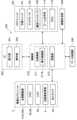
図1に、実施形態に係る眼科システムの構成例のブロック図を示す。実施形態に係る眼科システム1000は、眼科装置1と、眼科情報処理装置(眼科画像処理装置、眼科解析装置)500と、操作装置510と、表示装置520とを含む。[Ophthalmology system]
FIG. 1 shows a block diagram of a configuration example of an ophthalmologic system according to an embodiment. The
眼科装置1は、被検眼に対してOCTを実行することにより被検眼のデータを光学的に収集する。眼科装置1は、被検眼の所定の部位(眼底(網膜)又は前眼部)をスキャンすることにより被検眼の所定の部位のOCTデータ(干渉信号)を光学的に収集する。眼科装置1は、取得されたOCTデータから被検眼の所定の部位の画像を取得することが可能である。画像には、断層像及び正面画像が含まれる。断層像には、Bスキャン画像などがある。正面画像には、Cスキャン画像、en-face画像、シャドウグラム、又はプロジェクション画像などがある。眼科装置1は、取得された被検眼のデータ又は取得された画像のデータを眼科情報処理装置500に送信する。 The
いくつかの実施形態では、眼科装置1と眼科情報処理装置500とは、データ通信ネットワークを介して接続される。いくつかの実施形態に係る眼科情報処理装置500は、データ通信ネットワークを介して選択的に接続された複数の眼科装置1の1つから上記のデータを受信する。 In some embodiments, the
操作装置510及び表示装置520は、ユーザインターフェイス部として情報の表示、情報の入力、操作指示の入力など、眼科情報処理装置500とそのユーザとの間で情報をやりとりするための機能を提供する。操作装置510は、レバー、ボタン、キー、ポインティングデバイス等の操作デバイスを含む。いくつかの実施形態に係る操作装置510は、音で情報を入力するためのマイクロフォンを含む。表示装置520は、フラットパネルディスプレイ等の表示デバイスを含む。いくつかの実施形態では、操作装置510及び表示装置520の機能は、タッチパネルディスプレイのような入力機能を有するデバイスと表示機能を有するデバイスとが一体化されたデバイスにより実現される。いくつかの実施形態では、操作装置510及び表示装置520は、情報の入出力を行うためのグラフィカルユーザインターフェイス(GUI)を含む。 The operating
いくつかの実施形態では、眼科装置1は、眼科情報処理装置500、操作装置510、及び表示装置520の少なくとも1つの機能を有する。以下、眼科装置1が、眼科情報処理装置500、操作装置510、及び表示装置520の機能を有する場合について説明する。 In some embodiments, the
いくつかの実施形態では、眼科装置1は、上記のOCT計測を実行する機能に加えて、眼底カメラ、走査型レーザー検眼鏡、スリットランプ顕微鏡、及び手術用顕微鏡の少なくとも1つの機能を備える。いくつかの実施形態に係る眼科装置は、被検眼の光学的な特性を測定する機能を備える。被検眼の光学的な特性を測定する機能を備えた眼科装置には、レフラクトメーター、ケラトメーター、眼圧計、ウェーブフロントアナライザー、スペキュラーマイクロスコープ、視野計などがある。いくつかの実施形態に係る眼科装置は、レーザー治療に用いられるレーザー治療装置の機能を備える。 In some embodiments, the
以下、眼科装置1は、OCT計測機能と、眼底カメラの機能とを備える場合について説明する。 Hereinafter, a case will be described in which the
[眼科装置]
<光学系>
図2に、実施形態に係る眼科装置1の光学系の構成例を示す。[Ophthalmological equipment]
<Optical system>
FIG. 2 shows an example of the configuration of the optical system of the
図2に示すように、眼科装置1は、眼底カメラユニット2、OCTユニット100、及び演算制御ユニット200を含む。眼底カメラユニット2は、従来の眼底カメラとほぼ同様の光学系を有する。OCTユニット100には、OCTを実行するための光学系が設けられている。演算制御ユニット200は、各種の演算処理や制御処理等を実行するコンピュータを具備している。 As shown in FIG. 2, the
〔眼底カメラユニット〕
図2に示す眼底カメラユニット2には、被検眼Eの眼底Efの表面形態を表す2次元画像(眼底像)を取得するための光学系が設けられている。眼底像には、観察画像や撮影画像などが含まれる。観察画像は、例えば、近赤外光を用いて所定のフレームレートで形成されるモノクロの動画像である。撮影画像は、例えば、可視光をフラッシュ発光して得られるカラー画像、又は近赤外光若しくは可視光を照明光として用いたモノクロの静止画像であってもよい。眼底カメラユニット2は、これら以外の画像、例えばフルオレセイン蛍光画像やインドシアニングリーン蛍光画像や自発蛍光画像などを取得可能に構成されていてもよい。[Fundus camera unit]
The
眼底カメラユニット2には、被検者の顔を支持するための顎受けや額当てが設けられている。更に、眼底カメラユニット2には、照明光学系10と撮影光学系30とが設けられている。照明光学系10は眼底Efに照明光を照射する。撮影光学系30は、この照明光の眼底反射光を撮像装置(CCDイメージセンサ(単にCCDと呼ぶことがある)35、38、撮像装置は、CMOSイメージセンサ(単に、CMOSと呼ぶことがある)であってもよい)に導く。また、撮影光学系30は、OCTユニット100からの測定光を被検眼Eに導くとともに、被検眼Eを経由した測定光をOCTユニット100に導く。 The
照明光学系10の観察光源11は、例えばハロゲンランプ又はLED(Light Emitting Diode)により構成される。観察光源11から出力された光(観察照明光)は、曲面状の反射面を有する反射ミラー12により反射され、集光レンズ13を経由し、可視カットフィルタ14を透過して近赤外光となる。更に、観察照明光は、撮影光源15の近傍にて一旦集束し、ミラー16により反射され、リレーレンズ17、18、絞り19及びリレーレンズ20を経由する。そして、観察照明光は、孔開きミラー21の周辺部(孔部の周囲の領域)にて反射され、ダイクロイックミラー46を透過し、対物レンズ22により屈折されて眼底Efを照明する。 The observation
観察照明光の眼底反射光は、対物レンズ22により屈折され、ダイクロイックミラー46を透過し、孔開きミラー21の中心領域に形成された孔部を通過し、ダイクロイックミラー55を透過し、合焦レンズ31を経由し、ミラー32により反射される。更に、この眼底反射光は、ハーフミラー33Aを透過し、ダイクロイックミラー33により反射され、集光レンズ34によりCCDイメージセンサ35の受光面に結像される。CCDイメージセンサ35は、例えば所定のフレームレートで眼底反射光を検出する。表示装置3には、CCDイメージセンサ35により検出された眼底反射光に基づく画像(観察画像)が表示される。なお、撮影光学系30のピントが前眼部に合わせられている場合、被検眼Eの前眼部の観察画像が表示される。 The fundus reflected light of the observation illumination light is refracted by the
撮影光源15は、例えばキセノンランプ又はLEDにより構成される。撮影光源15から出力された光(撮影照明光)は、観察照明光と同様の経路を通って眼底Efに照射される。撮影照明光の眼底反射光は、観察照明光のそれと同様の経路を通ってダイクロイックミラー33まで導かれ、ダイクロイックミラー33を透過し、ミラー36により反射され、集光レンズ37によりCCDイメージセンサ38の受光面に結像される。表示装置3には、CCDイメージセンサ38により検出された眼底反射光に基づく画像(撮影画像)が表示される。なお、観察画像を表示する表示装置3と撮影画像を表示する表示装置3は、同一のものであってもよいし、異なるものであってもよい。また、被検眼Eを赤外光で照明して同様の撮影を行う場合には、赤外の撮影画像が表示される。また、撮影光源としてLEDを用いることも可能である。 The photographing light source 15 is composed of, for example, a xenon lamp or an LED. The light output from the photographing light source 15 (photographing illumination light) passes through the same path as the observation illumination light and is irradiated onto the fundus Ef. The fundus reflected light of the photography illumination light is guided to the
LCD(Liquid Crystal Display)39は、固視標や視力測定用指標を表示する。固視標は被検眼Eを固視させるための指標であり、眼底撮影時やOCT計測時などに使用される。 An LCD (Liquid Crystal Display) 39 displays fixation targets and visual acuity measurement indicators. The fixation target is an index for causing the subject's eye E to fixate, and is used during fundus photography, OCT measurement, and the like.
LCD39から出力された光は、その一部がハーフミラー33Aにて反射され、ミラー32により反射され、合焦レンズ31及びダイクロイックミラー55を経由し、孔開きミラー21の孔部を通過する。孔部を通過した光は、ダイクロイックミラー46を透過し、対物レンズ22により屈折されて眼底Efに投影される。LCD39の画面上における固視標の表示位置を変更することにより、被検眼Eの固視位置を変更できる。 A portion of the light output from the
更に、眼底カメラユニット2には、従来の眼底カメラと同様にアライメント光学系50とフォーカス光学系60とが設けられている。アライメント光学系50は、被検眼Eに対する装置光学系の位置合わせ(アライメント)を行うための指標(アライメント指標)を生成する。フォーカス光学系60は、被検眼Eに対してフォーカス(ピント)を合わせるための指標(スプリット指標)を生成する。 Further, the
アライメント光学系50のLED51から出力された光(アライメント光)は、絞り52、53及びリレーレンズ54を経由してダイクロイックミラー55により反射され、孔開きミラー21の孔部を通過する。孔部を通過した光は、ダイクロイックミラー46を透過し、対物レンズ22により被検眼Eの角膜に投影される。 The light (alignment light) output from the
アライメント光の角膜反射光は、対物レンズ22、ダイクロイックミラー46及び上記孔部を経由し、その一部がダイクロイックミラー55を透過し、合焦レンズ31を通過し、ミラー32により反射され、ハーフミラー33Aを透過する。ハーフミラー33Aを透過した光は、ダイクロイックミラー33により反射され、集光レンズ34によりCCDイメージセンサ35の受光面に投影される。CCDイメージセンサ35による受光像(アライメント指標)は、観察画像とともに表示装置3に表示される。ユーザは、従来の眼底カメラと同様の操作を行ってアライメントを実施する。また、演算制御ユニット200がアライメント指標の位置を解析して光学系を移動させることによりアライメントを行ってもよい(オートアライメント機能)。 The corneal reflected light of the alignment light passes through the
フォーカス調整を行う際には、照明光学系10の光路上に反射棒67の反射面が斜設される。フォーカス光学系60のLED61から出力された光(フォーカス光)は、リレーレンズ62を通過し、スプリット指標板63により2つの光束に分離され、二孔絞り64を通過する。二孔絞り64を通過した光は、ミラー65により反射され、集光レンズ66により反射棒67の反射面に一旦結像されて反射される。更に、フォーカス光は、リレーレンズ20を経由し、孔開きミラー21により反射され、ダイクロイックミラー46を透過し、対物レンズ22により屈折されて眼底Efに投影される。 When performing focus adjustment, the reflective surface of the
フォーカス光の眼底反射光は、アライメント光の角膜反射光と同様の経路を通ってCCDイメージセンサ35により検出される。CCDイメージセンサ35による受光像(スプリット指標)は、観察画像とともに表示装置3に表示される。演算制御ユニット200は、従来と同様に、スプリット指標の位置を解析して合焦レンズ31及びフォーカス光学系60を移動させてピント合わせを行う(オートフォーカス機能)。また、スプリット指標を視認しつつ手動でピント合わせを行ってもよい。 The fundus reflected light of the focus light is detected by the
ダイクロイックミラー46は、眼底撮影用の光路からOCT用の光路を分岐させている。ダイクロイックミラー46は、OCTに用いられる波長帯の光を反射し、眼底撮影用の光を透過させる。このOCT用の光路には、OCTユニット100側から順に、コリメータレンズユニット40と、光路長変更部41と、光スキャナ42と、合焦レンズ43と、ミラー44と、リレーレンズ45とが設けられている。合焦レンズ43は、OCT用の光路に沿って移動可能である。 The
光路長変更部41は、図2に示す矢印の方向に移動可能とされ、OCT用の光路の光路長を変更する。この光路長の変更は、被検眼Eの眼軸長に応じた光路長の補正や、干渉状態の調整などに利用される。光路長変更部41は、例えばコーナーキューブと、これを移動する機構とを含んで構成される。 The optical path
光スキャナ42は、被検眼Eの瞳孔と光学的に共役な位置に配置されている。光スキャナ42は、OCT用の光路を通過する光(測定光LS)の進行方向を変更する。それにより、被検眼Eを測定光LSでスキャンすることができる。光スキャナ42は、例えば、測定光LSをx方向にスキャンするガルバノミラーと、y方向にスキャンするガルバノミラーと、これらを独立に駆動する機構とを含んで構成される。それにより、測定光LSをxy平面上の任意の方向にスキャンすることができる。 The
〔OCTユニット〕
OCTユニット100の構成の一例を図3に示す。OCTユニット100には、被検眼Eの所定の部位に対するOCT計測を行うための光学系が設けられている。この光学系は、従来のスペクトラルドメインタイプのOCT装置と同様の構成を有する。すなわち、この光学系は、広帯域光源からの光(低コヒーレンス光)を参照光と測定光とに分割し、被検眼Eの眼底Efを経由した測定光と参照光路を経由した参照光とを干渉させて干渉光を生成し、この干渉光のスペクトル成分を検出するように構成されている。この検出結果(検出信号、干渉信号)は演算制御ユニット200に送られる。[OCT unit]
An example of the configuration of the
光源ユニット101は広帯域の低コヒーレンス光L0を出力する。低コヒーレンス光L0は、例えば、近赤外領域の波長帯(約800nm~900nm程度)を含み、数十マイクロメートル程度の時間的コヒーレンス長を有する。なお、人眼では視認できない波長帯、例えば1040~1060nm程度の中心波長を有する近赤外光を低コヒーレンス光L0として用いてもよい。 The
光源ユニット101は、スーパールミネセントダイオード(Super Luminescent Diode:SLD)や、LEDや、SOA(Semiconductor Optical Amplifier)等の光出力デバイスを含んで構成される。 The
光源ユニット101から出力された低コヒーレンス光L0は、光ファイバ102によりファイバカプラ103に導かれて測定光LSと参照光LRとに分割される。 Low coherence light L0 output from
参照光LRは、光ファイバ104により導かれてアッテネータ(光減衰器)105に到達する。アッテネータ105は、公知の技術を用いて、演算制御ユニット200の制御の下、光ファイバ104により導かれる参照光LRの光量を自動で調整する。アッテネータ105により光量が調整された参照光LRは、光ファイバ104により導かれて偏波コントローラ(偏波調整器)106に到達する。偏波コントローラ106は、例えば、ループ状にされた光ファイバ104に対して外部から応力を与えることで、光ファイバ104内を導かれる参照光LRの偏波状態を調整する装置である。なお、偏波コントローラ106の構成はこれに限定されるものではなく、任意の公知技術を用いることが可能である。偏波コントローラ106により偏波状態が調整された参照光LRは、ファイバカプラ109に到達する。 Reference light LR is guided by
ファイバカプラ103により生成された測定光LSは、光ファイバ107により導かれ、コリメータレンズユニット40により平行光束とされる。更に、測定光LSは、光路長変更部41、光スキャナ42、合焦レンズ43、ミラー44、及びリレーレンズ45を経由してダイクロイックミラー46に到達する。ダイクロイックミラー46に到達した測定光LSは、ダイクロイックミラー46により反射され、対物レンズ22により屈折されて眼底Efに照射される。測定光LSは、眼底Efの様々な深さ位置において散乱(反射を含む)される。眼底Efによる測定光LSの後方散乱光は、往路と同じ経路を逆向きに進行してファイバカプラ103に導かれ、光ファイバ108を経由してファイバカプラ109に到達する。 The measurement light LS generated by the
ファイバカプラ109は、測定光LSの後方散乱光と、アッテネータ105等を経由した参照光LRとを干渉させる。これにより生成された干渉光LCは、光ファイバ110により導かれて出射端111から出射される。更に、干渉光LCは、コリメータレンズ112により平行光束とされ、回折格子(分光器)113により分光(スペクトル分解)され、ズーム光学系114により集光されてCCDイメージセンサ115の受光面に投影される。なお、図3に示す回折格子113は透過型であるが、例えば反射型の回折格子など、他の形態の分光素子を用いることも可能である。 The
CCDイメージセンサ115は、例えばラインセンサ又は2次元センサであり、2以上の受光素子(検出素子)が配列され、分光された干渉光LCの各スペクトル成分を検出して電荷に変換する。CCDイメージセンサ115は、この電荷を蓄積して検出信号を生成し、これを演算制御ユニット200に送る。 The
この実施形態ではマイケルソン型の干渉計を採用しているが、例えばマッハツェンダー型など任意のタイプの干渉計を適宜に採用することが可能である。また、CCDイメージセンサに代えて、他の形態のイメージセンサ、例えばCMOS(Complementary Metal Oxide Semiconductor)イメージセンサなどを用いることが可能である。 Although a Michelson type interferometer is used in this embodiment, any type of interferometer such as a Mach-Zehnder type can be used as appropriate. Furthermore, instead of the CCD image sensor, it is possible to use another type of image sensor, such as a CMOS (Complementary Metal Oxide Semiconductor) image sensor.
<制御系>
〔演算制御ユニット〕
演算制御ユニット200の構成について図4~図7を参照しつつ説明する。なお、図4~図7においては、眼科装置1のいくつかの構成要素が省略されており、この実施形態を説明するために特に必要な構成要素が選択的に示されている。<Control system>
[Calculation control unit]
The configuration of the arithmetic and
演算制御ユニット200は、CCDイメージセンサ115から入力される検出信号を解析して被検眼EのOCT画像を形成する。そのための演算処理は、従来のスペクトラルドメインタイプのOCT装置と同様である。また、演算制御ユニット200は、眼底カメラユニット2、表示装置3及びOCTユニット100の各部を制御する。例えば演算制御ユニット200は、被検眼EのOCT画像を表示装置3に表示させる。演算制御ユニット200は、制御部210と、画像形成部220と、データ処理部230とを含む。 The
演算制御ユニット200は、例えば、従来のコンピュータと同様に、マイクロプロセッサ、RAM(Random Access Memory)、ROM(Read Only Memory)、ハードディスクドライブ、通信インターフェイスなどを含む。ハードディスクドライブ等の記憶装置には、眼科装置1を制御するためのコンピュータプログラムが記憶されている。演算制御ユニット200は、各種の回路基板、例えばOCT画像を形成するための回路基板を備えていてもよい。また、演算制御ユニット200は、キーボードやマウス等の操作デバイス(入力デバイス)や、LCD等の表示デバイスを備えていてもよい。 The
(制御部)
眼科装置1の制御系は、制御部210を中心に構成される。制御部210は、例えば、マイクロプロセッサ、RAM、ROM、ハードディスクドライブ、通信インターフェイス等を含んで構成される。制御部210には、主制御部211と記憶部212が設けられている。(control unit)
The control system of the
(主制御部)
主制御部211は前述の各種制御を行う。特に、図4に示すように、主制御部211は、眼底カメラユニット2に対し、合焦駆動部31A及び43A、CCDイメージセンサ35及び38、LCD39、光路長変更部41、及び光スキャナ42等を制御する。また、主制御部211は、OCTユニット100に対し、光源ユニット101、アッテネータ105、偏波コントローラ106、ズーム光学系114、及びCCDイメージセンサ115等を制御する。(Main control section)
The
合焦駆動部31Aは、主制御部211の制御の下、合焦レンズ31を光軸方向に移動させる。それにより、撮影光学系30の合焦位置が変更される。なお、主制御部211は、図示しない光学系駆動部を制御して、眼底カメラユニット2に設けられた光学系を3次元的に移動させることができる。この制御は、アライメントやトラッキングにおいて用いられる。トラッキングとは、被検眼Eの運動に合わせて装置光学系を移動させるものである。トラッキングを行う場合には、事前にアライメントとピント合わせが実行される。トラッキングは、被検眼Eを動画撮影して得られる画像に基づき被検眼Eの位置や向きに合わせて装置光学系をリアルタイムで移動させることにより、アライメントとピントが合った好適な位置関係を維持する機能である。 The focusing
合焦駆動部43Aは、主制御部211の制御の下、測定光LSの光路に沿って合焦レンズ43を移動させる。それにより、測定光LSの合焦位置が変更される。測定光LSの合焦位置は、測定光LSのビームウェストの深さ位置(z位置)に相当する。 The
光源ユニット101は、主制御部211の制御の下、点灯と非点灯とを切り換えたり、光源ユニット101から出力される光L0の光量を変更したりする。 Under the control of the
ズーム光学系114は、2以上のレンズ(例えば、2つの凸レンズと、2つの凸レンズの間に配置された1つの凹レンズ)を含み、主制御部211の制御の下、レンズ間隔の変更が可能に構成されている。レンズ間隔を変更することにより、画角が変更され、CCDイメージセンサ115の検出面における1検出素子あたりのスペクトルの波長幅を変更することが可能である。 The zoom
主制御部211は、図4に示すように、表示制御部211Aを含む。表示制御部211Aは、画像形成部220により形成されたOCT画像や、データ処理部230によるデータ処理後の情報などを表示装置3に表示させる。例えば、表示制御部211Aは、後述するように分散補償が行われた干渉信号に基づいて形成された被検眼Eの所定の部位の画像を表示装置3に表示させることが可能である。 The
(記憶部)
記憶部212は、各種のデータを記憶する。記憶部212に記憶されるデータとしては、例えば、OCT画像の画像データ、眼底像の画像データ、被検眼情報などがある。被検眼情報は、患者IDや氏名などの被検者に関する情報や、左眼/右眼の識別情報などの被検眼に関する情報を含む。また、記憶部212には、眼科装置1を動作させるための各種プログラムやデータが記憶されている。(Storage part)
The
(画像形成部)
画像形成部220は、CCDイメージセンサ115からの検出信号に基づいて、眼底Efの断層像の画像データを形成する。すなわち、画像形成部220は、干渉光学系による干渉光LCの検出結果に基づいて被検眼Eの画像データを形成する。この処理には、従来のスペクトラルドメインタイプのOCTと同様に、ノイズ除去(ノイズ低減)、フィルタ処理、FFT(Fast Fourier Transform)などの処理が含まれている。このようにして取得される画像データは、複数のAライン(被検眼E内における各測定光LSの経路)における反射強度プロファイルを画像化することにより形成された一群の画像データを含むデータセットである。(Image forming section)
The
画質を向上させるために、同じパターンでのスキャンを複数回繰り返して収集された複数のデータセットを重ね合わせる(加算平均する)ことができる。 To improve image quality, multiple data sets collected by scanning the same pattern multiple times can be overlapped (averaged).
画像形成部220は、例えば、前述の回路基板を含んで構成される。なお、この明細書では、「画像データ」と、それに基づく「画像」とを同一視することがある。また、被検眼Eの部位とその画像とを同一視することもある。 The
以上のように機能する画像形成部220は、例えば、1以上のプロセッサ、RAM、ROM、ハードディスクドライブ、回路基板等を含んで構成される。例えば、画像形成部220の機能は、1以上のプロセッサにより実現される。ハードディスクドライブ等の記憶装置には、上記機能をプロセッサに実行させるコンピュータプログラムがあらかじめ格納されている。 The
(データ処理部)
データ処理部230は、画像形成部220により形成されたOCT画像に対して各種のデータ処理(画像処理)や解析処理を施す。例えば、データ処理部230は、画像の輝度補正や分散補正等の補正処理を実行する。また、データ処理部230は、眼底カメラユニット2により得られた画像(眼底像、前眼部像等)に対して各種の画像処理や解析処理を施す。(Data processing section)
The
データ処理部230は、断層像の間の画素を補間する補間処理などの公知の画像処理を実行することにより、被検眼Eのボリュームデータ(ボクセルデータ)を形成することができる。ボリュームデータに基づく画像を表示させる場合、データ処理部230は、このボリュームデータに対してレンダリング処理を施して、特定の視線方向から見たときの擬似的な3次元画像を形成する。 The
データ処理部230は、眼底像とOCT画像との位置合わせを行うことができる。眼底像とOCT画像とが並行して取得される場合には、双方の光学系が同軸であることから、(ほぼ)同時に取得された眼底像とOCT画像とを、撮影光学系30の光軸を基準として位置合わせすることができる。また、眼底像とOCT画像との取得タイミングに関わらず、OCT画像のうち眼底Efの相当する画像領域の少なくとも一部をxy平面に投影して得られる正面画像と、眼底像との位置合わせをすることにより、そのOCT画像とその眼底像とを位置合わせすることも可能である。この位置合わせ手法は、眼底像取得用の光学系とOCT用の光学系とが同軸でない場合においても適用可能である。また、双方の光学系が同軸でない場合であっても、双方の光学系の相対的な位置関係が既知であれば、この相対位置関係を参照して同軸の場合と同様の位置合わせを実行することが可能である。 The
データ処理部230は、図5に示すように、分散補償処理部231と、解析部232とを含む。 The
分散補償処理部231は、被検眼Eに対するOCT計測により得られた干渉信号から、測定光路と参照光路との差に対応した波長分散量を特定し、特定された波長分散量に基づいて当該干渉信号に対して分散補償処理を施す。この実施形態では、OCT計測の経路は、例えば、光源ユニット101を始点として、測定光LSの光路、参照光LRの光路、及び干渉光LCの光路を経由して検出素子としてのCCDイメージセンサ115に至るまでの光路に相当する。 The dispersion
解析部232は、分散補償処理部231により分散補償処理が施された干渉信号を用いて所定の解析処理を行う。いくつかの実施形態では、解析部232は、分散補償処理が施された干渉信号に基づいて形成されたOCT画像に対して所定の解析処理を行う。 The
所定の解析処理には、被検眼Eにおける所定の部位(組織、病変部)の特定;指定された部位間の距離、面積、角度、比率、密度の算出;指定された計算式による演算;所定の部位の形状の特定;これらの統計値の算出;計測値、統計値の分布の算出;これら解析処理結果に基づく画像処理などがある。所定の組織には、血管、視神経乳頭、中心窩、黄斑などがある。所定の病変部には、白斑、出血、剥離部、浮腫、腫瘍、ドルーゼンなどがある。 The predetermined analysis process includes identifying a predetermined region (tissue, lesion) in the eye E to be examined; calculating the distance, area, angle, ratio, and density between the specified regions; calculation using a specified calculation formula; calculation of statistical values; calculation of distribution of measured values and statistical values; and image processing based on the results of these analysis processes. Predetermined tissues include blood vessels, optic disc, fovea, macula, and the like. The predetermined lesions include vitiligo, hemorrhage, exfoliation, edema, tumor, drusen, and the like.
部位間の距離には、網膜における層領域の層厚、眼内距離が含まれる。網膜における層領域には、内境界膜、神経繊維層、神経節細胞層、内網状層、内顆粒層、外網状層、外顆粒層、外境界膜、視細胞層、RPEがある。部位間の距離には、ブルッフ膜、脈絡膜、強膜などが含まれてよい。眼内距離には、眼軸長、角膜厚、前房深度、水晶体厚、硝子体厚などがある。 The distance between regions includes the layer thickness of the layer region in the retina and the intraocular distance. The layer regions in the retina include the inner limiting membrane, the nerve fiber layer, the ganglion cell layer, the inner plexiform layer, the inner nuclear layer, the outer plexiform layer, the outer nuclear layer, the outer limiting membrane, the photoreceptor layer, and the RPE. Distances between regions may include Bruch's membrane, choroid, sclera, and the like. Intraocular distances include axial length, corneal thickness, anterior chamber depth, crystalline lens thickness, and vitreous thickness.
(分散補償処理部)
図6に示すように、分散補償処理部231は、リスケーリング部231Aと、分散特定部231Bと、分散補償部231Cとを含む。(Dispersion compensation processing section)
As shown in FIG. 6, the dispersion
(リスケーリング部)
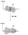
リスケーリング部231Aは、図8Aに示すように、CCDイメージセンサ115により得られた干渉光の検出結果である干渉信号Sgに対してリスケーリング処理を施す。リスケーリング処理は、波長等間隔軸で測定された干渉信号を波数等間隔軸に設定し直す処理である。(Rescaling part)
As shown in FIG. 8A, the
(分散特定部)
分散特定部231Bは、リスケーリング部231Aによりリスケーリング処理が施された干渉信号から、OCT計測における測定光路と参照光路との差に対応した波長分散量を特定する。(Dispersion Specification Department)
The
ここで、リスケーリング部231Aによりリスケーリング処理が施された干渉信号I(k)は、式(1)に示すように表すことができる。 Here, the interference signal I(k) subjected to the rescaling process by the

式(1)において、kは波数を表し、S(k)は光源ユニット101から出力される光のスペクトルを示す関数を表し、Rrは参照光路の反射率を表し、Rsは測定光路の反射率を表し、φは位相を表す。 In equation (1), k represents the wave number, S(k) represents a function indicating the spectrum of light output from the
様々な屈折率を有する媒質を通る光の位相φ(k)は、式(1)に示す干渉信号に対してヒルベルト変換(Hilbert Transform)を施すことにより得られる。得られた位相φ(k)は、式(2)に示すようにTaylor展開することができる。 The phase φ(k) of light passing through media having various refractive indices can be obtained by applying Hilbert Transform to the interference signal shown in equation (1). The obtained phase φ(k) can be subjected to Taylor expansion as shown in equation (2).

式(2)において、k0は光源ユニット101から出力される光の中心波数を表す。式(2)の2(n=2)次以上の項は、スペクトルの幅を広げてしまい、ピーク強度を下げる。分散特定部231Bは、式(2)に示す2次以上の高次の項の少なくとも一部をOCT計測の経路(OCT計測における経路差)に対応した波長分散量として特定する。In equation (2), k0 represents the center wave number of light output from the
このような分散特定部231Bは、図7に示すように、ヒルベルト変換部233と、第1フィッティング部234と、差分算出部235と、第2フィッティング部236とを含む。 As shown in FIG. 7, the
(ヒルベルト変換部)
ヒルベルト変換部233は、上記のように、リスケーリング部231Aによりリスケーリング処理が施された干渉信号に対してヒルベルト変換処理を施す。それにより、式(2)に示す位相φ(k)が得られる。ヒルベルト変換処理を行うことにより、例えば、図8Bに示すように、干渉信号Sgの振幅成分Apと位相成分Phを抽出される。位相成分Phは、式(2)に示す1次以上の項に相当する。(Hilbert transform part)
The
いくつかの実施形態では、ヒルベルト変換部233によるヒルベルト変換処理により得られた位相成分Phから、OCT計測の経路に対応した波長分散量が特定される。この場合、後述の分散補償部231Cは、干渉信号Sgに対して、特定された波長分散量に基づいて分散補償を行う。 In some embodiments, the amount of chromatic dispersion corresponding to the path of OCT measurement is specified from the phase component Ph obtained by Hilbert transform processing by the
(第1フィッティング部)
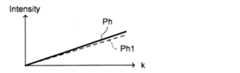
第1フィッティング部234は、図8Cに示すように、ヒルベルト変換部233によるヒルベルト変換処理により得られた位相成分Phを公知の手法で1次関数でフィッティングし、得られた1次関数Ph1を出力する。1次関数Ph1は、式(2)に示す1次の項に相当する。(1st fitting part)
As shown in FIG. 8C, the first
(差分算出部)
差分算出部235は、ヒルベルト変換部233によるヒルベルト変換処理により得られた干渉信号の位相成分phから、第1フィッティング部234によるフィッティング処理により得られた1次関数Ph1を減算する。差分算出部235により得られた差分は、式(2)に示す2次以上の高次の項に相当する。(Difference calculation part)
The
いくつかの実施形態では、差分算出部235により得られた差分から、OCT計測の経路に対応した波長分散量が特定される。この場合、後述の分散補償部231Cは、干渉信号Sgに対して、特定された波長分散量に基づいて分散補償を行う。 In some embodiments, the amount of chromatic dispersion corresponding to the path of OCT measurement is specified from the difference obtained by the
(第2フィッティング部)
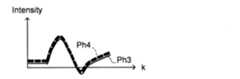
第2フィッティング部236は、図8Dに示すように、差分算出部235により得られた差分Ph3を公知の手法で3次以上の高次の関数(例えば、4次関数)でフィッティングし、得られた高次の関数Ph4を出力する。関数Ph4は、分散補償関数である。(Second fitting part)
As shown in FIG. 8D, the second
(分散補償部)
分散補償部231Cは、分散特定部231Bにより特定されたOCT計測の経路に対応した波長分散量に基づいて、干渉信号Sgに対して分散補償処理を施す。具体的には、分散補償部231Cは、第2フィッティング部236によるフィッティング処理により得られた高次の関数Ph4を用いて干渉信号Sgに対して分散補償処理を施す。(Dispersion compensation section)
The
例えば、分散補償前の干渉信号をI(k)と表し、分散補償後の干渉信号をI´(k)と表すと、分散補償部231Cは、式(3)に示すような演算処理を行うことにより分散補償処理を行う。 For example, if the interference signal before dispersion compensation is expressed as I(k), and the interference signal after dispersion compensation is expressed as I'(k), then the

以上のような分散補償を行うことにより、OCT計測の経路に対応した波長分散量を補償(キャンセル)することができるようになる。OCT計測の経路に対応した波長分散量には、OCT計測の経路上に配置された光学素子の波長分散量、OCT計測対象の被検眼Eの波長分散量、リスケーリング処理による波長分散量が含まれる。 By performing the dispersion compensation as described above, it becomes possible to compensate (cancel) the amount of chromatic dispersion corresponding to the path of OCT measurement. The amount of chromatic dispersion corresponding to the path of OCT measurement includes the amount of chromatic dispersion of the optical element placed on the path of OCT measurement, the amount of chromatic dispersion of the eye E to be measured by OCT, and the amount of chromatic dispersion due to rescaling processing. It will be done.
特に、光源ユニット101から出力される光の中心波数k0は、製造ばらつきによる個体差や経年変化によって必ずしも一定ではない。しかしながら、実施形態では、OCT計測の経路に対応した波長分散量には、OCT計測時に光源ユニット101から出力される光の中心波数k0のバラツキに起因した波長分散量も含まれる。それにより、簡素な処理で、OCT計測時点での波長分散量(OCT計測時点での光学系の状態、及び被検眼に応じた波長分散量)を補償することができるようになる。In particular, the central wave number k0 of the light output from the
以上のように機能するデータ処理部230は、例えば、1以上のプロセッサ、RAM、ROM、ハードディスクドライブ、回路基板等を含んで構成される。例えば、データ処理部230の機能は、1以上のプロセッサにより実現される。いくつかの実施形態では、データ処理部230の各部の機能は、各部に対応して設けられた1以上のプロセッサにより実現される。ハードディスクドライブ等の記憶装置には、上記機能をプロセッサに実行させるコンピュータプログラムがあらかじめ格納されている。 The
(ユーザインターフェイス)
図4に示すように、ユーザインターフェイス240には、表示部241と操作部242とが含まれる。表示部241は、前述した演算制御ユニット200の表示デバイスや表示装置3を含んで構成される。操作部242は、前述した演算制御ユニット200の操作デバイスを含んで構成される。操作部242には、眼科装置1の筐体や外部に設けられた各種のボタンやキーが含まれていてもよい。また、表示部241は、眼底カメラユニット2の筺体に設けられたタッチパネルなどの各種表示デバイスを含んでいてもよい。(user interface)
As shown in FIG. 4, the
なお、表示部241と操作部242は、それぞれ個別のデバイスとして構成される必要はない。例えばタッチパネルのように、表示機能と操作機能とが一体化されたデバイスを用いることも可能である。その場合、操作部242は、このタッチパネルとコンピュータプログラムとを含んで構成される。操作部242に対する操作内容は、電気信号として制御部210に入力される。また、表示部241に表示されたグラフィカルユーザインターフェイス(GUI)と、操作部242とを用いて、操作や情報入力を行うようにしてもよい。 Note that the
表示部241は、図1に示す表示装置520の機能を実現する。操作部242は、図1に示す操作装置510の機能を実現する。 The
OCTユニット100から対物レンズ22までの光学系は、実施形態に係る「干渉光学系」の一例である。表示装置3又は表示部241は、実施形態に係る「表示手段」の一例である。分散特定部231Bは、実施形態に係る「特定部」の一例である。演算制御ユニット200は、実施形態に係る「眼科情報処理装置」の一例である。 The optical system from the
[動作例]
眼科装置1の動作について説明する。以下では、被検眼Eの眼底Efに対してOCT計測を行う場合について説明する。[Operation example]
The operation of the
図9及び図10に、実施形態に係る眼科装置1の動作例のフロー図を示す。図9及び図10は、実施形態に係る眼科装置1の動作例のフローチャートを表す。図10は、図9のステップS3の動作例のフローチャートを表す。記憶部212には、図9及び図10に示す処理を実現するためのコンピュータプログラムが記憶されている。主制御部211は、このコンピュータプログラムに従って動作することにより、図9及び図10に示す処理を実行する。 9 and 10 show flowcharts of operation examples of the
(S1:アライメント)
まず、主制御部211は、アライメントを実行する。(S1: Alignment)
First, the
すなわち、主制御部211は、アライメント光学系50を制御して、被検眼Eにアライメント指標を投影させる。このとき、被検眼Eには、LCD39による固視標も投影される。主制御部211は、例えばCCDイメージセンサ35により取得された受光像に基づいて特定された光学系の移動量に基づいて図示しない移動機構を制御し、被検眼Eに対して光学系を当該移動量だけ相対的に移動させる。主制御部211は、この処理を繰り返し実行させる。いくつかの実施形態では、ステップS1におけるアライメント完了後に、フォーカス光学系60を用いたフォーカス調整が行われる。 That is, the
(S2:OCT計測)
続いて、主制御部211は、OCTユニット100等を制御して被検眼Eの眼底Efに対してOCT計測を実行する。これにより、眼底EfをOCT計測対象とする干渉信号が取得される。(S2: OCT measurement)
Next, the
例えば、ステップS1からステップS2に移行したとき、まず、主制御部211は、LCD39の所定位置にOCT計測用の固視標を表示させる。主制御部211は、眼底Efにおける光学系の光軸の位置に対応するLCD39の表示位置に固視標を表示させることが可能である。その後、主制御部211は、OCTユニット100等を制御して、事前に設定されたスキャンエリアに対して測定光LSを用いたスキャンを開始させる。いくつかの実施形態では、スキャンエリアは、眼底Efの形態に応じて自動で設定される。いくつかの実施形態では、ユーザが表示部241に表示された眼底Efの画像を見ながら操作部242を用いて眼底Efに対してスキャンエリアを設定する。 For example, when moving from step S1 to step S2, the
ステップS2において、スキャンエリア内の複数の測定位置(入射位置)における干渉信号(Aスキャン方向)が得られる。ステップS2において得られた干渉信号は、例えば、記憶部212に保存される。 In step S2, interference signals (in the A-scan direction) at a plurality of measurement positions (incidence positions) within the scan area are obtained. The interference signal obtained in step S2 is stored in the
(S3:分散補償)
次に、主制御部211は、ステップS2において得られた干渉信号に対する分散補償を分散補償処理部231に行わせる。これにより、ステップS2におけるスキャンエリア内の複数の測定位置における、分散補償処理後の干渉信号が得られる。ステップS3の詳細は、後述する。(S3: Dispersion compensation)
Next, the
(S4:解析処理)
続いて、主制御部211は、ステップS3において得られた分散補償処理後の干渉信号を用いて所定の解析処理を解析部232に実行させる。解析部232は、上記の解析処理を行う。(S4: Analysis processing)
Next, the
例えば、主制御部211は、ステップS3において得られた分散補償処理後の干渉信号に基づいてOCT画像を画像形成部220に形成させ、形成されたOCT画像を用いて上記の解析処理を解析部232に実行させる。 For example, the
また、例えば、主制御部211は、ステップS3において得られた分散補償処理後の干渉信号に基づいてOCT画像を画像形成部220に形成させ、形成されたOCT画像を表示部241に表示させる。 Further, for example, the
以上で、眼科装置1の処理は終了である(エンド)。 This is the end of the processing of the ophthalmological apparatus 1 (END).
図9のステップS3では、図10に示すように処理が実行される。 In step S3 of FIG. 9, processing is executed as shown in FIG.
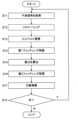
(S11:干渉信号を取得)
まず、主制御部211は、ステップS2において得られた干渉信号を取得する。例えば、主制御部211は、ステップS2において記憶部212に保存された1つのAスキャンに対応した干渉信号を読み出す。(S11: Obtain interference signal)
First, the
(S12:リスケ-リング)
次に、主制御部211は、ステップS11において取得された干渉信号に対してリスケ-リング処理をリスケーリング部231Aに実行させる。(S12: Rescaling)
Next, the
例えば、リスケーリング部231Aは、図8Aに示すように、干渉信号に対してリスケ-リング処理を実行する。 For example, the
(S13:ヒルベルト変換)
次に、主制御部211は、ステップS12において得られたリスケ-リング処理後の干渉信号に対してヒルベルト変換処理をヒルベルト変換部233に実行させる。(S13: Hilbert transformation)
Next, the
例えば、ヒルベルト変換部233は、図8Bに示すように、リスケ-リング処理後の干渉信号に対して公知のヒルベルト変換を実行する。これにより、リスケ-リング処理後の干渉信号の位相成分が抽出される。 For example, the
(S14:第1フィッティング処理)
次に、主制御部211は、ステップS13において得られた干渉信号の位相成分を1次関数でフィッティングする第1フィッティング処理を第1フィッティング部234に実行させる。(S14: First fitting process)
Next, the
例えば、第1フィッティング部234は、図8Cに示すように、干渉信号の位相成分を1次関数でフィッティングする。 For example, the first
(S15:差分を算出)
次に、主制御部211は、ステップS13において得られた干渉信号の位相成分から、ステップS14において得られた1次関数を差分算出部235に減算させる。(S15: Calculate the difference)
Next, the
例えば、差分算出部235は、上記のように、式(2)に示す2次以上の高次の項を算出する。 For example, the
(S16:第2フィッティング処理)
次に、主制御部211は、ステップS15において得られた差分を4次関数でフィッティングする第2フィッティング処理を第2フィッティング部236に実行させる。(S16: Second fitting process)
Next, the
例えば、第2フィッティング部236は、図8Dに示すように、ステップS15において得られた差分を4次関数でフィッティングする。 For example, the second
(S17:分散補償)
続いて、主制御部211は、ステップS16において得られた4次関数を用いて、ステップS11において得られた干渉信号に対して分散補償処理を分散補償部231Cに実行させる。(S17: Dispersion compensation)
Next, the
例えば、分散補償部231Cは、式(3)に示す演算処理を行うことで、当該Aスキャンにより得られた干渉信号に対して分散補償処理を行う。 For example, the
(S18:次?)
次に、主制御部211は、次に分散補償を行うべき干渉信号あるか否かを判定する。例えば、主制御部211は、スキャンエリア内の複数の測定位置に対してあらかじめ決められた順序でステップS11~ステップS17が実行されたか否かを判定することにより、次に分散補償を行うべき干渉信号があるか否かを判定することが可能である。或いは、例えば、主制御部211は、ステップS11~ステップS17の一連の処理の実行回数があらかじめ決められた回数であるか否かを判定することにより、次に分散補償を行うべき干渉信号があるか否かを判定することが可能である。(S18: Next?)
Next, the
次に分散補償を行うべき干渉信号があると判定されたとき(S18:Y)、眼科装置1の動作はステップS11に移行する。次に分散補償を行うべき干渉信号があると判定されなかったとき(S18:N)、眼科装置1の動作は終了である(エンド)。 When it is determined that there is an interference signal for which dispersion compensation should be performed next (S18: Y), the operation of the
実施形態に係る眼科情報処理方法は、実施形態に係る眼科情報処理装置によって実現される。いくつかの実施形態では、上記の眼科情報処理方法をコンピュータに実行させるためのプログラムが提供される。このようなプログラムを、コンピュータによって読み取り可能な非一時的な(non-transitory)任意の記録媒体に記憶させることができる。記録媒体は、磁気、光、光磁気、半導体などを利用した電子媒体であってよい。典型的には、記録媒体は、磁気テープ、磁気ディスク、光ディスク、光磁気ディスク、フラッシュメモリ、ソリッドステートドライブなどである。また、インターネットやLAN等のネットワークを通じてこのプログラムを送受信することも可能である。 The ophthalmological information processing method according to the embodiment is realized by the ophthalmological information processing apparatus according to the embodiment. In some embodiments, a program for causing a computer to execute the above ophthalmological information processing method is provided. Such a program can be stored on any non-transitory computer readable storage medium. The recording medium may be an electronic medium using magnetism, light, magneto-optical, semiconductor, or the like. Typically, the recording medium is a magnetic tape, magnetic disk, optical disk, magneto-optical disk, flash memory, solid state drive, or the like. It is also possible to send and receive this program via a network such as the Internet or LAN.
[作用・効果]
実施形態に係る眼科情報処理装置、眼科装置、眼科情報処理方法、及びプログラムの作用及び効果について説明する。[Action/Effect]
The operations and effects of the ophthalmologic information processing device, ophthalmologic device, ophthalmologic information processing method, and program according to the embodiment will be described.
いくつかの実施形態に係る眼科情報処理装置(500、演算制御ユニット200)は、特定部(分散特定部231B)と、分散補償部(231C)とを含む。特定部は、被検眼(E)における所定の部位(例えば、眼底(網膜))に対するOCT計測における測定光路と参照光路との差に対応した波長分散量を特定する。分散補償部は、所定の部位に対するOCT計測により得られた干渉信号に対し、波長分散量に基づいて分散補償を行う。 The ophthalmological information processing device (500, arithmetic control unit 200) according to some embodiments includes a specifying section (
このような構成によれば、干渉信号からOCT計測における測定光路と参照光路との差に対応した波長分散量を特定し、特定された波長分散量に基づいて干渉信号に対して分散補償を行うようにしたので、光学系の経年変化やOCT計測対象の被検眼にかかわらず、簡素な処理で、高精度なOCT計測結果を取得することができるようになる。 According to such a configuration, the amount of chromatic dispersion corresponding to the difference between the measurement optical path and the reference optical path in OCT measurement is specified from the interference signal, and dispersion compensation is performed for the interference signal based on the specified amount of chromatic dispersion. This makes it possible to obtain highly accurate OCT measurement results with simple processing, regardless of the aging of the optical system or the eye to be measured by OCT.
いくつかの実施形態では、特定部は、干渉信号に対してヒルベルト変換を行うヒルベルト変換部(233)を含み、ヒルベルト変換を行うことにより得られた干渉信号の位相成分に基づいて波長分散量を特定する。 In some embodiments, the identifying unit includes a Hilbert transform unit (233) that performs Hilbert transform on the interference signal, and calculates the amount of chromatic dispersion based on the phase component of the interference signal obtained by performing the Hilbert transform. Identify.
このような構成によれば、干渉信号から位相成分を抽出し、抽出された位相成分に基づいて波長分散量を特定するようにしたので、簡素な処理で分散補償を行うことが可能になる。 According to this configuration, the phase component is extracted from the interference signal, and the amount of chromatic dispersion is specified based on the extracted phase component, so that dispersion compensation can be performed with simple processing.
いくつかの実施形態では、特定部は、位相成分を1次関数でフィッティングする第1フィッティング部(234)と、位相成分から第1フィッティング部により得られた1次関数を減算する差分算出部(235)と、を含み、差分算出部により算出された差分に基づいて波長分散量を特定する。 In some embodiments, the identification unit includes a first fitting unit (234) that fits the phase component with a linear function, and a difference calculation unit (234) that subtracts the linear function obtained by the first fitting unit from the phase component. 235), and specifies the amount of chromatic dispersion based on the difference calculated by the difference calculating section.
このような構成によれば、干渉信号の位相成分をフィッティングすることにより得られた1次関数を位相成分から減算することで波長分散量を特定するようにしたので、簡素な処理で分散補償を行うことが可能になる。 With this configuration, the amount of chromatic dispersion is determined by subtracting the linear function obtained by fitting the phase component of the interference signal from the phase component, so dispersion compensation can be achieved with simple processing. It becomes possible to do so.
いくつかの実施形態では、特定部は、差分を2次以上の高次の関数でフィッティングする第2フィッティング部(236)を含み、第2フィッティング部により得られた関数に基づいて波長分散量を特定する。 In some embodiments, the identification unit includes a second fitting unit (236) that fits the difference with a function of second order or higher order, and calculates the amount of chromatic dispersion based on the function obtained by the second fitting unit. Identify.
このような構成によれば、上記の差分をフィッティングすることにより得られた2次以上の高次の関数に基づいて波長分散量を特定するようにしたので、簡素な処理で分散補償を行うことが可能になる。 According to such a configuration, the amount of chromatic dispersion is specified based on a higher-order function of second order or higher obtained by fitting the above-mentioned difference, so dispersion compensation can be performed with simple processing. becomes possible.
いくつかの実施形態では、特定部は、Aスキャン毎に波長分散量を特定し、分散補償部は、Aスキャン毎に分散補償を行う。 In some embodiments, the identification unit identifies the amount of chromatic dispersion for each A-scan, and the dispersion compensation unit performs dispersion compensation for each A-scan.
このような構成によれば、Aスキャン毎に、波長分散量を特定し、特定された波長分散量に基づいて干渉信号に対して分散補償を行うようにしたので、簡素な処理で、高精度なOCT計測結果を取得することが可能になる。 With this configuration, the amount of chromatic dispersion is specified for each A-scan, and dispersion compensation is performed for the interference signal based on the specified amount of chromatic dispersion, so that high precision can be achieved with simple processing. It becomes possible to obtain accurate OCT measurement results.
いくつかの実施形態は、分散補償部により分散補償が行われた干渉信号に基づいて所定の部位の画像を形成する画像形成部(220)と、画像形成部により形成された画像を表示手段(表示装置520、表示部241)に表示させる表示制御部(211A)と、を含む。 Some embodiments include an image forming section (220) that forms an image of a predetermined region based on an interference signal subjected to dispersion compensation by a dispersion compensator, and a display section (220) that displays the image formed by the image forming section. The
このような構成によれば、OCT計測により得られた干渉信号に基づいて形成される画像の画質を向上させることが可能になる。 According to such a configuration, it is possible to improve the image quality of an image formed based on an interference signal obtained by OCT measurement.
いくつかの実施形態は、分散補償部により分散補償が行われた干渉信号に基づいて眼内距離を特定する解析部(232)を含む。 Some embodiments include an analysis unit (232) that identifies the intraocular distance based on the interference signal for which dispersion compensation has been performed by the dispersion compensation unit.
このような構成によれば、OCT計測により得られた干渉信号に基づいて特定される眼内距離の精度を向上させることが可能になる。 According to such a configuration, it is possible to improve the accuracy of the intraocular distance specified based on the interference signal obtained by OCT measurement.
いくつかの実施形態では、所定の部位は、網膜を含む。 In some embodiments, the predetermined site includes the retina.
このような構成によれば、装置光学系から網膜までのOCT計測の経路における波長分散量を補償することが可能になる。 With such a configuration, it is possible to compensate for the amount of chromatic dispersion in the OCT measurement path from the apparatus optical system to the retina.
いくつかの実施形態に係る眼科装置(1)は、光源(光源ユニット101)からの光(L0)を測定光(LS)と参照光(LR)とに分割し、測定光を被検眼に照射し、被検眼からの戻り光と参照光との干渉光(LC)を検出する干渉光学系(OCTユニット100から対物レンズ22までの光学系)と、上記のいずれかに記載の眼科情報処理装置と、を含む。 The ophthalmological apparatus (1) according to some embodiments divides light (L0) from a light source (light source unit 101) into measurement light (LS) and reference light (LR), and irradiates the eye to be examined with the measurement light. and an interference optical system (optical system from the
このような構成によれば、光学系の経年変化やOCT計測対象の被検眼にかかわらず、簡素な処理で、高精度なOCT計測結果を取得することが可能な眼科装置を提供することができるようになる。 According to such a configuration, it is possible to provide an ophthalmological apparatus that is capable of obtaining highly accurate OCT measurement results through simple processing, regardless of the aging of the optical system or the subject's eye to be measured by OCT. It becomes like this.
いくつかの実施形態に係る眼科情報処理方法は、被検眼(E)における所定の部位(例えば、眼底(網膜))に対するOCT計測における測定光路と参照光路との差に対応した波長分散量を特定する特定ステップと、所定の部位に対するOCT計測により得られた干渉信号に対し、波長分散量に基づいて分散補償を行う分散補償ステップと、を含む。 The ophthalmological information processing method according to some embodiments specifies the amount of chromatic dispersion corresponding to the difference between the measurement optical path and the reference optical path in OCT measurement of a predetermined part (for example, the fundus (retina)) of the eye (E) to be examined. and a dispersion compensation step of performing dispersion compensation on the interference signal obtained by OCT measurement of a predetermined region based on the amount of chromatic dispersion.
このような方法によれば、干渉信号からOCT計測における測定光路と参照光路との差に対応した波長分散量を特定し、特定された波長分散量に基づいて干渉信号に対して分散補償を行うようにしたので、光学系の経年変化やOCT計測対象の被検眼にかかわらず、簡素な処理で、高精度なOCT計測結果を取得することができるようになる。 According to such a method, the amount of chromatic dispersion corresponding to the difference between the measurement optical path and the reference optical path in OCT measurement is specified from the interference signal, and dispersion compensation is performed for the interference signal based on the specified amount of chromatic dispersion. This makes it possible to obtain highly accurate OCT measurement results with simple processing, regardless of the aging of the optical system or the eye to be measured by OCT.
いくつかの実施形態では、特定ステップは、干渉信号に対してヒルベルト変換を行うヒルベルト変換ステップを含み、ヒルベルト変換を行うことにより得られた干渉信号の位相成分に基づいて波長分散量を特定する。 In some embodiments, the identifying step includes a Hilbert transform step of performing a Hilbert transform on the interference signal, and identifying the amount of chromatic dispersion based on a phase component of the interference signal obtained by performing the Hilbert transform.
このような方法によれば、干渉信号から位相成分を抽出し、抽出された位相成分に基づいて波長分散量を特定するようにしたので、簡素な処理で分散補償を行うことが可能になる。 According to this method, the phase component is extracted from the interference signal, and the amount of chromatic dispersion is specified based on the extracted phase component, so that dispersion compensation can be performed with simple processing.
いくつかの実施形態では、特定ステップは、位相成分を1次関数でフィッティングする第1フィッティングステップと、位相成分から第1フィッティングステップにおいて得られた1次関数を減算する差分算出ステップと、を含み、差分算出ステップにおいて算出された差分に基づいて波長分散量を特定する。 In some embodiments, the identifying step includes a first fitting step of fitting the phase component with a linear function, and a difference calculation step of subtracting the linear function obtained in the first fitting step from the phase component. , the amount of chromatic dispersion is specified based on the difference calculated in the difference calculation step.
このような方法によれば、干渉信号の位相成分をフィッティングすることにより得られた1次関数を位相成分から減算することで波長分散量を特定するようにしたので、簡素な処理で分散補償を行うことが可能になる。 According to this method, the amount of chromatic dispersion is determined by subtracting the linear function obtained by fitting the phase component of the interference signal from the phase component, so dispersion compensation can be achieved with simple processing. It becomes possible to do so.
いくつかの実施形態では、特定ステップは、差分を2次以上の高次の関数でフィッティングする第2フィッティングステップを含み、第2フィッティングステップにおいて得られた関数に基づいて波長分散量を特定する。 In some embodiments, the identifying step includes a second fitting step of fitting the difference with a higher-order function of second order or higher, and the amount of chromatic dispersion is identified based on the function obtained in the second fitting step.
このような方法によれば、上記の差分をフィッティングすることにより得られた2次以上の高次の関数に基づいて波長分散量を特定するようにしたので、簡素な処理で分散補償を行うことが可能になる。 According to this method, the amount of chromatic dispersion is specified based on a function of higher order than second order obtained by fitting the above-mentioned difference, so dispersion compensation can be performed with simple processing. becomes possible.
いくつかの実施形態では、特定ステップは、Aスキャン毎に波長分散量を特定し、分散補償ステップは、Aスキャン毎に分散補償を行う。 In some embodiments, the identifying step identifies the amount of chromatic dispersion for each A-scan, and the dispersion compensation step performs dispersion compensation for each A-scan.
このような方法によれば、Aスキャン毎に、波長分散量を特定し、特定された波長分散量に基づいて干渉信号に対して分散補償を行うようにしたので、簡素な処理で、高精度なOCT計測結果を取得することが可能になる。 According to this method, the amount of chromatic dispersion is specified for each A-scan, and dispersion compensation is performed for the interference signal based on the specified amount of chromatic dispersion, so it is possible to achieve high precision with simple processing. It becomes possible to obtain accurate OCT measurement results.
いくつかの実施形態は、分散補償ステップにおいて分散補償が行われた干渉信号に基づいて所定の部位の画像を形成する画像形成ステップと、画像形成ステップにおいて形成された画像を表示手段(表示装置520、表示部241)に表示させる表示制御ステップと、を含む。 Some embodiments include an image forming step of forming an image of a predetermined region based on the interference signal subjected to dispersion compensation in the dispersion compensation step, and a display unit (display device 520) for displaying the image formed in the image forming step. , a display control step of displaying the information on the display unit 241).
このような方法によれば、OCT計測により得られた干渉信号に基づいて形成される画像の画質を向上させることが可能になる。 According to such a method, it is possible to improve the image quality of an image formed based on an interference signal obtained by OCT measurement.
いくつかの実施形態は、分散補償ステップにおいて分散補償が行われた干渉信号に基づいて眼内距離を特定する解析ステップを含む。 Some embodiments include an analysis step that determines the intraocular distance based on the dispersion compensated interference signal in the dispersion compensation step.
このような方法によれば、OCT計測により得られた干渉信号に基づいて特定される眼内距離の精度を向上させることが可能になる。 According to such a method, it is possible to improve the accuracy of the intraocular distance specified based on the interference signal obtained by OCT measurement.
いくつかの実施形態では、所定の部位は、網膜を含む。 In some embodiments, the predetermined site includes the retina.
このような方法によれば、装置光学系から網膜までのOCT計測の経路における波長分散量を補償することが可能になる。 According to such a method, it becomes possible to compensate for the amount of chromatic dispersion in the OCT measurement path from the device optical system to the retina.
いくつかの実施形態に係るプログラムは、コンピュータに、上記のいずれかに記載の眼科情報処理方法の各ステップを実行させる。 A program according to some embodiments causes a computer to execute each step of any of the ophthalmological information processing methods described above.
このようなプログラムによれば、干渉信号からOCT計測の経路に対応した波長分散量を特定し、特定された波長分散量に基づいて干渉信号に対して分散補償を行うようにしたので、光学系の経年変化やOCT計測対象の被検眼にかかわらず、簡素な処理で、高精度なOCT計測結果を取得することができるようになる。 According to such a program, the amount of chromatic dispersion corresponding to the path of OCT measurement is specified from the interference signal, and dispersion compensation is performed for the interference signal based on the specified amount of chromatic dispersion, so the optical system It becomes possible to obtain highly accurate OCT measurement results through simple processing, regardless of the aging of the eye or the subject's eye to be measured by OCT.
以上に説明した構成は、この発明を好適に実施するための一例に過ぎない。よって、この発明の要旨の範囲内における任意の変形(省略、置換、付加等)を適宜に施すことが可能である。適用される構成は、例えば目的に応じて選択される。また、適用される構成に応じ、当業者にとって自明の作用効果や、本明細書において説明された作用効果が得られる。 The configuration described above is only one example for suitably implementing the present invention. Therefore, any modification (omission, substitution, addition, etc.) can be made as appropriate within the scope of the gist of the present invention. The configuration to be applied is selected depending on the purpose, for example. Further, depending on the applied configuration, effects that are obvious to those skilled in the art and effects described in this specification can be obtained.
1 眼科装置
2 眼底カメラユニット
3、520 表示装置
100 OCTユニット
200 演算制御ユニット
210 制御部
211 主制御部
211A 表示制御部
212 記憶部
220 画像形成部
230 データ処理部
231 分散補償処理部
231A リスケーリング部
231B 分散特定部
231C 分散補償部
232 解析部
233 ヒルベルト変換部
234 第1フィッティング部
235 差分算出部
236 第2フィッティング部
240 ユーザインターフェイス
241 表示部
242 操作部
500 眼科情報処理装置
510 操作装置
1000 眼科システム
E 被検眼1
Claims (14)
Translated fromJapanese前記所定の部位に対するOCT計測により得られた干渉信号に対し、前記波長分散量に基づいて分散補償を行う分散補償部と、
を含み、
前記特定部は、
前記干渉信号に対してヒルベルト変換を行うヒルベルト変換部と、
前記ヒルベルト変換を行うことにより得られた前記干渉信号の位相成分を1次関数でフィッティングする第1フィッティング部と、
前記位相成分から前記第1フィッティング部により得られた1次関数を減算する差分算出部と、
を含み、
前記差分算出部により算出された差分に基づいて前記波長分散量を特定する、眼科情報処理装置。an identification unit that identifies an amount of chromatic dispersion corresponding to a difference between a measurement optical path and a reference optical path in OCT measurement for a predetermined part of the eye to be examined;
a dispersion compensation unit that performs dispersion compensation on the interference signal obtained by OCT measurement of the predetermined portion based on the amount of chromatic dispersion;
including;
The specific part is
a Hilbert transform unit that performs Hilbert transform on the interference signal;
a first fitting unit that fits a phase component of the interference signal obtained by performing the Hilbert transform with a linear function;
a difference calculation unit that subtracts the linear function obtained by the first fitting unit from the phase component;
including;
An ophthalmological information processing devicethat specifies the chromatic dispersion amount based on the difference calculated by the difference calculation unit .
前記差分を2次以上の高次の関数でフィッティングする第2フィッティング部
を含み、
前記第2フィッティング部により得られた関数に基づいて前記波長分散量を特定する
ことを特徴とする請求項1に記載の眼科情報処理装置。The specific part is
a second fitting unit that fits the difference with a higher-order function of second order or higher;
The ophthalmological information processing apparatus according to claim1, wherein the chromatic dispersion amount is specified based on a function obtained by the second fitting section.
前記分散補償部は、Aスキャン毎に前記分散補償を行う
ことを特徴とする請求項1又は請求項2に記載の眼科情報処理装置。The specifying unit specifies the chromatic dispersion amount for each A scan,
The ophthalmologic information processing apparatus according to claim 1or 2 , wherein the dispersion compensation unit performs the dispersion compensation for each A scan.
前記画像形成部により形成された前記画像を表示手段に表示させる表示制御部と、
を含む
ことを特徴とする請求項1~請求項3のいずれか一項に記載の眼科情報処理装置。an image forming unit that forms an image of the predetermined region based on the interference signal subjected to dispersion compensation by the dispersion compensator;
a display control unit that causes a display unit to display the image formed by the image forming unit;
The ophthalmological information processing device according to any one of claims 1 to3 , characterized in that it includes:
ことを特徴とする請求項1~請求項4のいずれか一項に記載の眼科情報処理装置。The ophthalmological information processing device according to any one of claims 1 to4 , further comprising an analysis unit that specifies an intraocular distance based on an interference signal subjected to dispersion compensation by the dispersion compensation unit. .
ことを特徴とする請求項1~請求項5のいずれか一項に記載の眼科情報処理装置。The ophthalmological information processing device according to any one of claims 1 to5 , wherein the predetermined region includes a retina.
請求項1~請求項6のいずれか一項に記載の眼科情報処理装置と、
を含む、眼科装置。an interference optical system that divides light from a light source into measurement light and reference light, irradiates the test eye with the measurement light, and detects interference light between return light from the test eye and the reference light;
The ophthalmological information processing device according to any one of claims 1 to6 ,
Ophthalmic equipment, including.
前記所定の部位に対するOCT計測により得られた干渉信号に対し、前記波長分散量に基づいて分散補償を行う分散補償ステップと、
を含み、
前記特定ステップは、
前記干渉信号に対してヒルベルト変換を行うヒルベルト変換ステップと、
前記ヒルベルト変換を行うことにより得られた前記干渉信号の位相成分を1次関数でフィッティングする第1フィッティングステップと、
前記位相成分から前記第1フィッティングステップにおいて得られた1次関数を減算する差分算出ステップと、
を含み、
前記差分算出ステップにおいて算出された差分に基づいて前記波長分散量を特定する、眼科情報処理方法。a specifying step of specifying the amount of chromatic dispersion corresponding to the difference between the measurement optical path and the reference optical path in OCT measurement for a predetermined part of the eye to be examined;
a dispersion compensation step of performing dispersion compensation on the interference signal obtained by OCT measurement of the predetermined portion based on the amount of chromatic dispersion;
including;
The identifying step includes:
a Hilbert transform step of performing a Hilbert transform on the interference signal;
a first fitting step of fitting the phase component of the interference signal obtained by performing the Hilbert transform with a linear function;
a difference calculation step of subtracting the linear function obtained in the first fitting step from the phase component;
including;
An ophthalmological information processing method, wherein the chromatic dispersion amount is specified based on the difference calculated in the difference calculation step .
前記差分を2次以上の高次の関数でフィッティングする第2フィッティングステップ
を含み、
前記第2フィッティングステップにおいて得られた関数に基づいて前記波長分散量を特定する
ことを特徴とする請求項8に記載の眼科情報処理方法。The identifying step includes:
a second fitting step of fitting the difference with a higher-order function of second order or higher;
The ophthalmological information processing method according to claim8 , wherein the chromatic dispersion amount is specified based on the function obtained in the second fitting step.
前記分散補償ステップは、Aスキャン毎に前記分散補償を行う
ことを特徴とする請求項8又は請求項9に記載の眼科情報処理方法。The specifying step specifies the chromatic dispersion amount for each A scan,
The ophthalmologic information processing method according to claim8 or 9 , wherein the dispersion compensation step performs the dispersion compensation for each A scan.
前記画像形成ステップにおいて形成された前記画像を表示手段に表示させる表示制御ステップと、
を含む
ことを特徴とする請求項8~請求項10のいずれか一項に記載の眼科情報処理方法。an image forming step of forming an image of the predetermined region based on the interference signal subjected to dispersion compensation in the dispersion compensation step;
a display control step of displaying the image formed in the image forming step on a display means;
The ophthalmological information processing method according to any one of claims8 to10 , comprising:
ことを特徴とする請求項8~請求項11のいずれか一項に記載の眼科情報処理方法。The ophthalmological information processing method according to any one of claims8 to11 , further comprising an analysis step of specifying an intraocular distance based on the interference signal subjected to dispersion compensation in the dispersion compensation step. .
ことを特徴とする請求項8~請求項12のいずれか一項に記載の眼科情報処理方法。The ophthalmological information processing method according to any one of claims8 to12 , wherein the predetermined region includes a retina.
Priority Applications (1)
| Application Number | Priority Date | Filing Date | Title |
|---|---|---|---|
| JP2020040527AJP7412229B2 (en) | 2020-03-10 | 2020-03-10 | Ophthalmology information processing device, ophthalmology device, ophthalmology information processing method, and program |
Applications Claiming Priority (1)
| Application Number | Priority Date | Filing Date | Title |
|---|---|---|---|
| JP2020040527AJP7412229B2 (en) | 2020-03-10 | 2020-03-10 | Ophthalmology information processing device, ophthalmology device, ophthalmology information processing method, and program |
Publications (2)
| Publication Number | Publication Date |
|---|---|
| JP2021141943A JP2021141943A (en) | 2021-09-24 |
| JP7412229B2true JP7412229B2 (en) | 2024-01-12 |
Family
ID=77765307
Family Applications (1)
| Application Number | Title | Priority Date | Filing Date |
|---|---|---|---|
| JP2020040527AActiveJP7412229B2 (en) | 2020-03-10 | 2020-03-10 | Ophthalmology information processing device, ophthalmology device, ophthalmology information processing method, and program |
Country Status (1)
| Country | Link |
|---|---|
| JP (1) | JP7412229B2 (en) |
Citations (3)
| Publication number | Priority date | Publication date | Assignee | Title |
|---|---|---|---|---|
| JP2008501118A (en) | 2004-05-29 | 2008-01-17 | ザ ジェネラル ホスピタル コーポレイション | Chromatic dispersion compensation process, system and software configuration using refractive layer in optical coherence tomography (OCT) imaging |
| JP2017185342A (en) | 2017-07-18 | 2017-10-12 | 株式会社トプコン | Optical image measuring device |
| JP2019150409A (en) | 2018-03-06 | 2019-09-12 | 株式会社ニデック | Oct apparatus |
- 2020
- 2020-03-10JPJP2020040527Apatent/JP7412229B2/enactiveActive
Patent Citations (3)
| Publication number | Priority date | Publication date | Assignee | Title |
|---|---|---|---|---|
| JP2008501118A (en) | 2004-05-29 | 2008-01-17 | ザ ジェネラル ホスピタル コーポレイション | Chromatic dispersion compensation process, system and software configuration using refractive layer in optical coherence tomography (OCT) imaging |
| JP2017185342A (en) | 2017-07-18 | 2017-10-12 | 株式会社トプコン | Optical image measuring device |
| JP2019150409A (en) | 2018-03-06 | 2019-09-12 | 株式会社ニデック | Oct apparatus |
Non-Patent Citations (1)
| Title |
|---|
| Maciej Wojtkowski, et al.,Ultrahigh-resolution, high-speed, Fourier domain optical coherence tomography and methods for dispersion compensation,Optics Express,米国,Optical Society of America,2004年05月31日,Vol.12, No.11,2404-2422 |
Also Published As
| Publication number | Publication date |
|---|---|
| JP2021141943A (en) | 2021-09-24 |
Similar Documents
| Publication | Publication Date | Title |
|---|---|---|
| JP6009935B2 (en) | Ophthalmic equipment | |
| JP6045895B2 (en) | Ophthalmic observation device | |
| JP5543171B2 (en) | Optical image measuring device | |
| JP6776076B2 (en) | OCT device | |
| JP2022176282A (en) | Ophthalmologic apparatus and control method thereof | |
| JP6901264B2 (en) | Ophthalmic equipment | |
| JP2023080218A (en) | ophthalmic equipment | |
| JP7096392B2 (en) | Ophthalmic equipment | |
| JP6452977B2 (en) | Ophthalmic imaging apparatus and control method thereof | |
| JP6779674B2 (en) | OCT device | |
| JP6159454B2 (en) | Ophthalmic observation device | |
| JP7335107B2 (en) | Ophthalmic information processing device, ophthalmic device, ophthalmic information processing method, and program | |
| JP2023175006A (en) | Ophthalmologic apparatus and control method thereof | |
| JP6934747B2 (en) | Ophthalmic device and its control method | |
| JP7412229B2 (en) | Ophthalmology information processing device, ophthalmology device, ophthalmology information processing method, and program | |
| JP6809926B2 (en) | Ophthalmic equipment | |
| JP7359724B2 (en) | Ophthalmology information processing device, ophthalmology device, ophthalmology information processing method, and program | |
| WO2022176828A1 (en) | Ophthalmic information processing device, ophthalmic device, ophthalmic information processing method, and program | |
| JP6557388B2 (en) | Ophthalmic imaging equipment | |
| WO2021149430A1 (en) | Ophthalmic information processing device, ophthalmic device, ophthalmic information processing method, and program | |
| JP7096391B2 (en) | Ophthalmic equipment | |
| JP6664992B2 (en) | Ophthalmic imaging equipment | |
| JP7684158B2 (en) | Ophthalmic information processing device, ophthalmic device, ophthalmic information processing method, and program | |
| JP7202819B2 (en) | Ophthalmic device and its control method | |
| JP6756873B2 (en) | Ophthalmologic imaging equipment |
Legal Events
| Date | Code | Title | Description |
|---|---|---|---|
| A621 | Written request for application examination | Free format text:JAPANESE INTERMEDIATE CODE: A621 Effective date:20230216 | |
| A977 | Report on retrieval | Free format text:JAPANESE INTERMEDIATE CODE: A971007 Effective date:20230810 | |
| A131 | Notification of reasons for refusal | Free format text:JAPANESE INTERMEDIATE CODE: A131 Effective date:20230905 | |
| A521 | Request for written amendment filed | Free format text:JAPANESE INTERMEDIATE CODE: A523 Effective date:20230919 | |
| TRDD | Decision of grant or rejection written | ||
| A01 | Written decision to grant a patent or to grant a registration (utility model) | Free format text:JAPANESE INTERMEDIATE CODE: A01 Effective date:20231205 | |
| A61 | First payment of annual fees (during grant procedure) | Free format text:JAPANESE INTERMEDIATE CODE: A61 Effective date:20231226 | |
| R150 | Certificate of patent or registration of utility model | Ref document number:7412229 Country of ref document:JP Free format text:JAPANESE INTERMEDIATE CODE: R150 |