JP7409204B2 - Vehicle control device - Google Patents
Vehicle control deviceDownload PDFInfo
- Publication number
- JP7409204B2 JP7409204B2JP2020066605AJP2020066605AJP7409204B2JP 7409204 B2JP7409204 B2JP 7409204B2JP 2020066605 AJP2020066605 AJP 2020066605AJP 2020066605 AJP2020066605 AJP 2020066605AJP 7409204 B2JP7409204 B2JP 7409204B2
- Authority
- JP
- Japan
- Prior art keywords
- vehicle
- preceding vehicle
- deceleration
- speed
- target
- Prior art date
- Legal status (The legal status is an assumption and is not a legal conclusion. Google has not performed a legal analysis and makes no representation as to the accuracy of the status listed.)
- Active
Links
- 238000000034methodMethods0.000claimsdescription25
- 230000008569processEffects0.000claimsdescription24
- 238000004364calculation methodMethods0.000description61
- 238000011156evaluationMethods0.000description49
- 238000010586diagramMethods0.000description27
- 230000001133accelerationEffects0.000description24
- 230000006870functionEffects0.000description23
- 238000012545processingMethods0.000description14
- 238000005457optimizationMethods0.000description13
- 230000008859changeEffects0.000description12
- 238000001514detection methodMethods0.000description10
- 230000002093peripheral effectEffects0.000description9
- 238000013459approachMethods0.000description5
- 238000012937correctionMethods0.000description5
- 230000007423decreaseEffects0.000description5
- 230000033001locomotionEffects0.000description5
- 238000012986modificationMethods0.000description5
- 230000004048modificationEffects0.000description5
- 238000004891communicationMethods0.000description4
- 230000036461convulsionEffects0.000description4
- 230000005484gravityEffects0.000description4
- 101100208381Caenorhabditis elegans tth-1 geneProteins0.000description3
- 238000005259measurementMethods0.000description3
- 238000012508change requestMethods0.000description2
- 230000000052comparative effectEffects0.000description2
- 230000000994depressogenic effectEffects0.000description2
- 230000033228biological regulationEffects0.000description1
- 230000005540biological transmissionEffects0.000description1
- 238000006073displacement reactionMethods0.000description1
- 238000005516engineering processMethods0.000description1
- 238000010191image analysisMethods0.000description1
- 238000012886linear functionMethods0.000description1
- 238000003825pressingMethods0.000description1
- 238000012887quadratic functionMethods0.000description1
- 230000004044responseEffects0.000description1
Images


Landscapes
- Control Of Driving Devices And Active Controlling Of Vehicle (AREA)
- Controls For Constant Speed Travelling (AREA)
- Traffic Control Systems (AREA)
Description
Translated fromJapanese本発明は、車両制御装置に係り、特に、運転者による車両の運転を支援する車両制御装置に関する。 The present invention relates to a vehicle control device, and particularly to a vehicle control device that supports a driver in driving a vehicle.
従来、所定の予測期間(例えば、3秒間)が経過するまでの将来の走行経路を算出し、この走行経路上を車両が走行するように車両の挙動を制御する車両制御装置が知られている(例えば、特許文献1参照)。特許文献1に記載の車両制御装置では、このような走行経路が先行車を追従する際にも適用される。 Conventionally, a vehicle control device is known that calculates a future travel route until a predetermined prediction period (for example, 3 seconds) has elapsed, and controls the behavior of the vehicle so that the vehicle travels on this travel route. (For example, see Patent Document 1). In the vehicle control device described in
また、車両が先行車に追従して走行する際に、先行車の減速度を考慮に入れて車両の挙動を制御する技術が提案されている(例えば、特許文献2参照)。特許文献2に記載の装置では、先行車の減速開始直後から先行車の減速度に応じて車両の減速度が決定されるので、例えば、先行車が一時的に減速したときに車両が先行車に急接近することを抑制することができる。 Furthermore, a technique has been proposed in which, when a vehicle follows a preceding vehicle, the behavior of the vehicle is controlled by taking into account the deceleration of the preceding vehicle (for example, see Patent Document 2). In the device described in Patent Document 2, the deceleration of the vehicle is determined according to the deceleration of the preceding vehicle immediately after the preceding vehicle starts decelerating, so that, for example, when the preceding vehicle temporarily decelerates, the vehicle It is possible to prevent the vehicle from approaching rapidly.
特許文献2に記載の上記技術を特許文献1に記載の車両制御に適用すれば、先行車の減速時に車両が先行車に急接近するような予測走行経路の算出を回避することができると考えられる。 It is believed that if the above technology described in Patent Document 2 is applied to the vehicle control described in
引用文献1及び2に基づく車両制御装置では、先行車の減速が開始されたとき、先行車の減速が将来の予測期間にわたって継続すると予測され、この予測に基づいて車両の走行経路が算出されることになる。しかしながら、ブレーキ操作は多くの場合、短時間(例えば、1秒程度)で終了する。このため、上述のような走行経路の算出では、先行車の減速量が過大に見積もられることになる。したがって、このように算出された走行経路に基づいて車両が制御されると、車両が過剰に減速されるため、運転者に違和感を与えてしまう。 In the vehicle control devices based on
本発明は、このような問題を解決するためになされたものであり、先行車に追従するように車両の走行を支援する車両制御装置において、先行車の減速時において、車両が過剰に減速されることを抑制することが可能な車両制御装置を提供することを目的としている。 The present invention has been made in order to solve such problems, and is a vehicle control device that supports the running of a vehicle so as to follow a preceding vehicle. It is an object of the present invention to provide a vehicle control device that can suppress such problems.
上述した課題を解決するために、本発明は、車両の運転を支援するための車両制御装置であって、先行車の予測走行挙動に基づいて、先行車に追従するための所定の予測期間にわたる走行経路を算出する処理と、車両が走行経路を走行するための車両の制御目標値を算出する処理とを、予測期間より短い所定の制御周期毎に繰り返し実行するように構成されており、先行車が減速している場合、先行車の現在の減速度を、予測期間の始端における先行車の第1の減速度に設定し、第1の減速度よりも小さい減速度を、予測期間の終端における先行車の第2の減速度に設定し、予測期間において、先行車の減速度が第1の減速度から第2の減速度に変化するように、先行車の予測走行挙動を設定することを特徴としている。 In order to solve the above-mentioned problems, the present invention is a vehicle control device for supporting vehicle driving, and the present invention provides a vehicle control device that supports vehicle driving over a predetermined prediction period for following a preceding vehicle based on the predicted driving behavior of the preceding vehicle. The process of calculating the driving route and the process of calculating the vehicle control target value for the vehicle to travel along the driving route are repeatedly executed at predetermined control cycles shorter than the prediction period. If the car is decelerating, set the current deceleration of the preceding vehicle to the first deceleration of the preceding vehicle at the beginning of the prediction period, and set the deceleration smaller than the first deceleration to the end of the prediction period. and setting the predicted driving behavior of the preceding vehicle so that the deceleration of the preceding vehicle changes from the first deceleration to the second deceleration in the prediction period. It is characterized by
このように構成された本発明によれば、先行車の予想走行挙動に応じて車両が先行車に追従するように、予測期間にわたる車両の走行経路が算出され、この走行経路を走行するように車両の制御目標値が算出される。本発明では、このような走行経路は、例えば、車両と先行車との車間距離又は車間時間が車両の速度に応じて一定に維持されるように計算される。走行経路により、車両は走行経路上の各目標点における目標位置と目標速度等が設定される。そして、本発明では、追従時に先行車が減速した場合、先行車の現在の減速度が維持されるとの予測に基づく先行車の予測走行挙動に代えて、典型的な車両のブレーキ操作に沿うような予測走行挙動が用いられる。すなわち、本発明では、先行車の減速度が、予測期間の始端における減速度よりも終端における減速度の方が小さく設定される。これにより、本発明では、先行車に対して車両の過剰な減速が抑制され、先行車と車両との間の車間距離又は車間時間の変動を抑制することができる。なお、仮に先行車の減速度が長時間にわたって維持されたとしても、所定の制御周期毎に走行経路が繰り返し計算されるので、車両が十分に減速できずに先行車との車間距離や車間時間が極端に短くなることは回避される。 According to the present invention configured in this way, the travel route of the vehicle over a prediction period is calculated so that the vehicle follows the preceding vehicle according to the predicted travel behavior of the preceding vehicle, and the vehicle travels along this travel route. A control target value for the vehicle is calculated. In the present invention, such a travel route is calculated such that, for example, the inter-vehicle distance or inter-vehicle time between the vehicle and the preceding vehicle is maintained constant depending on the speed of the vehicle. Depending on the travel route, a target position, target speed, etc. at each target point on the travel route are set for the vehicle. In the present invention, when the preceding vehicle decelerates during following, instead of the predicted driving behavior of the preceding vehicle based on the prediction that the current deceleration of the preceding vehicle will be maintained, the driving behavior is based on the predicted driving behavior of the preceding vehicle, which is based on the prediction that the current deceleration of the preceding vehicle will be maintained. Predicted driving behavior such as this is used. That is, in the present invention, the deceleration of the preceding vehicle is set to be smaller at the end of the prediction period than at the beginning. As a result, in the present invention, excessive deceleration of the vehicle relative to the preceding vehicle can be suppressed, and fluctuations in the inter-vehicle distance or inter-vehicle time between the preceding vehicle and the vehicle can be suppressed. Even if the deceleration of the preceding vehicle is maintained for a long period of time, the driving route is repeatedly calculated at each predetermined control cycle, so the vehicle may not be able to decelerate sufficiently and the distance and time between the preceding vehicle and is avoided from becoming extremely short.
本発明において、好ましくは、車両制御装置は、第2の減速度をゼロに設定し、予測期間において、先行車の減速度が第1の減速度から第2の減速度に線形的に変化するように、先行車の予測走行挙動を設定する。このように構成された本発明によれば、一般的に想定される車両の減速挙動に沿って先行車の予測走行挙動が設定されるので、先行車の実際の走行挙動と予測走行挙動との差異を小さくすることができる。 In the present invention, preferably, the vehicle control device sets the second deceleration to zero, and the deceleration of the preceding vehicle changes linearly from the first deceleration to the second deceleration in the prediction period. The predicted driving behavior of the preceding vehicle is set as follows. According to the present invention configured in this way, the predicted driving behavior of the preceding vehicle is set in accordance with the generally assumed deceleration behavior of the vehicle, so that the actual driving behavior of the preceding vehicle and the predicted driving behavior are The difference can be reduced.
本発明において、好ましくは、車両制御装置は、先行車の前方に赤信号が検出されない場合よりも、先行車の前方に赤信号が検出される場合の方が、第2の減速度を大きな値に設定する。 In the present invention, preferably, the vehicle control device sets the second deceleration to a larger value when a red light is detected in front of the preceding vehicle than when no red light is detected in front of the preceding vehicle. Set to .
本発明において、具体的には、車両制御装置は、予測期間において、始端から所定の閾値期間経過後は、先行車の減速度が第2の減速度に維持されるように、先行車の予測走行挙動を設定し、先行車の前方に赤信号が検出されない場合よりも、先行車の前方に赤信号が検出される場合の方が、閾値期間を長く設定する。 In the present invention, specifically, the vehicle control device predicts the preceding vehicle so that the deceleration of the preceding vehicle is maintained at the second deceleration after a predetermined threshold period has elapsed from the starting point during the prediction period. The driving behavior is set, and the threshold period is set longer when a red light is detected in front of the preceding vehicle than when no red light is detected in front of the preceding vehicle.
一般的に赤信号により車両が停止する場合はブレーキペダルがより長く且つより大きな力で踏み続けられる。よって、本発明では、第2の減速度をより大きな値に設定し、及び/又は、閾値時間をより長い時間に設定することにより、先行車の実際の走行挙動に合わせて予測走行挙動を設定することができる。 Generally, when a vehicle is stopped due to a red light, the brake pedal is depressed for a longer period of time and with greater force. Therefore, in the present invention, the predicted driving behavior is set in accordance with the actual driving behavior of the preceding vehicle by setting the second deceleration to a larger value and/or setting the threshold time to a longer time. can do.
本発明において、好ましくは、車両制御装置は、先行車の前方の所定距離以内にカーブ路が存在しない場合よりも、先行車の前方の所定距離以内にカーブ路が存在する場合の方が、第2の減速度を小さな値に設定する。 In the present invention, preferably, the vehicle control device is configured to control the vehicle control device more when a curved road exists within a predetermined distance in front of the preceding vehicle than when there is no curved road within a predetermined distance in front of the preceding vehicle. Set the deceleration of 2 to a small value.
一般的にカーブ路への進入前に車両が減速する場合は大きな減速度が長時間維持されることは少ない。よって、本発明では、カーブ路への進入前において、第2の減速度をより小さな値に設定することにより、先行車の実際の走行挙動に合わせて予測走行挙動を設定することができる。 Generally, when a vehicle decelerates before entering a curved road, a large deceleration is rarely maintained for a long time. Therefore, in the present invention, by setting the second deceleration to a smaller value before entering a curved road, the predicted driving behavior can be set in accordance with the actual driving behavior of the preceding vehicle.
本発明において、好ましくは、車両制御装置は、予測期間において、始端から所定の閾値期間経過後は、先行車の減速度が第2の減速度に維持されるように、先行車の予測走行挙動を設定し、先行車の前方の所定距離以内に存在するカーブ路の曲率半径が小さいほど、及び/又は、先行車の速度が大きいほど、閾値期間を長く設定する。 In the present invention, preferably, the vehicle control device controls the predicted driving behavior of the preceding vehicle so that the deceleration of the preceding vehicle is maintained at the second deceleration after a predetermined threshold period has elapsed from the start point in the prediction period. The threshold period is set longer as the radius of curvature of a curved road existing within a predetermined distance in front of the preceding vehicle is smaller and/or as the speed of the preceding vehicle is greater.
一般的にカーブ路の曲率半径が小さい場合や、カーブ路への進入前の車両の速度が大きい場合は、比較的長い時間にわたって車両においてブレーキ操作が継続される。よって、本発明では、カーブ路の曲率半径が小さいほど、及び/又は、先行車の速度が大きいほど、閾値期間を長く設定することにより、先行車の実際の走行挙動に合わせて予測走行挙動を設定することができる。 Generally, when the radius of curvature of a curved road is small or when the speed of the vehicle before entering the curved road is high, the brake operation is continued in the vehicle for a relatively long time. Therefore, in the present invention, the smaller the radius of curvature of the curved road and/or the greater the speed of the preceding vehicle, the longer the threshold period is set, thereby adjusting the predicted driving behavior to match the actual driving behavior of the preceding vehicle. Can be set.
本発明の車両制御装置によれば、先行車の減速時において、車両が過剰に減速されることを抑制することができる。 According to the vehicle control device of the present invention, it is possible to prevent the vehicle from being excessively decelerated when the preceding vehicle decelerates.
以下、添付図面を参照して、本発明の実施形態による車両制御装置について説明する。
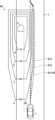
まず、図1及び図2を参照して、車両制御装置の構成について説明する。図1Aは車両制御装置の構成図、図1Bは運転者操作部の詳細を示す図、図2は車両制御装置の制御ブロック図である。DESCRIPTION OF THE PREFERRED EMBODIMENTS A vehicle control device according to an embodiment of the present invention will be described below with reference to the accompanying drawings.
First, the configuration of the vehicle control device will be described with reference to FIGS. 1 and 2. FIG. 1A is a configuration diagram of the vehicle control device, FIG. 1B is a diagram showing details of a driver operation section, and FIG. 2 is a control block diagram of the vehicle control device.
本実施形態の車両制御装置100は、これを搭載した車両1(図4等参照)に対して複数の運転支援モードにより、それぞれ異なる運転支援制御を提供するように構成されている。運転者は、複数の運転支援モードから所望の運転支援モードを選択可能である。 The
図1Aに示すように、車両制御装置100は、車両1に搭載されており、車両制御演算部(ECU)10と、複数のセンサ及びスイッチと、複数の制御システムと、運転支援モードについてのユーザ入力を行うための運転者操作部35を備えている。複数のセンサ及びスイッチには、車載カメラ21,ミリ波レーダ22,車両の挙動を検出する複数の挙動センサ(車速センサ23,加速度センサ24,ヨーレートセンサ25,舵角センサ26,アクセルセンサ27,ブレーキセンサ28),測位システム29,ナビゲーションシステム30が含まれる。また、複数の制御システムには、エンジン制御システム31,ブレーキ制御システム32,ステアリング制御システム33が含まれる。 As shown in FIG. 1A, a
図1Bに示すように、運転者操作部35は、運転者が操作可能なように車両1の車室内に設けられており、複数の運転支援モードから所望の運転支援モードを選択するためのモード設定操作部として機能する。運転者操作部35には、速度制限モードを設定するためのISAスイッチ36aと、先行車追従モードを設定するためのTJAスイッチ36bと、自動速度制御モードを設定するためのACCスイッチ36cと、レーンキープ制御モードを設定するためのLASスイッチ36dが設けられている。さらに、運転者操作部35には、先行車追従モードにおける車間距離(実質的には、車間距離に代わる車間時間)を設定するための距離設定スイッチ37aと、自動速度制御モード等における車速を設定するための車速設定スイッチ37bと、を備えている。 As shown in FIG. 1B, the
図1Aに示すECU10は、プロセッサ,各種プログラムを記憶するメモリ,入出力装置等を備えたコンピュータにより構成される。ECU10は、運転者操作部35から受け取った運転支援モード選択信号や設定車速信号、及び、複数のセンサ及びスイッチから受け取った信号に基づき、エンジン制御システム31,ブレーキ制御システム32,ステアリング制御システム33に対して、それぞれエンジンシステム,ブレーキシステム,ステアリングシステムを適宜に作動させるための要求信号を出力可能に構成されている。 The
車載カメラ21は、車両1の周囲を撮像し、撮像した画像データを出力する。ECU10は、画像データに基づいて対象物(例えば、車両、歩行者、道路、区画線(車線境界線、白線、黄線)、交通信号、交通標識、停止線、交差点、障害物等)を特定する。さらに、本実施形態においては、車載カメラ21として、車両を運転中の運転者を撮像する車室内カメラも備えている。なお、ECU10は、交通インフラや車々間通信等によって、車載通信機器を介して外部から対象物の情報を取得してもよい。 The vehicle-mounted
ミリ波レーダ22は、対象物(特に、先行車、駐車車両、歩行者、障害物等)の位置及び速度を測定する測定装置であり、車両1の前方へ向けて電波(送信波)を送信し、対象物により送信波が反射されて生じた反射波を受信する。そして、ミリ波レーダ22は、送信波と受信波に基づいて、車両1と対象物との間の距離(例えば、車間距離)や車両1に対する対象物の相対速度を測定する。なお、本実施形態において、ミリ波レーダ22に代えて、レーザレーダや超音波センサ等を用いて対象物との距離や相対速度を測定するように構成してもよい。また、複数のセンサを用いて、位置及び速度測定装置を構成してもよい。 The
車速センサ23は、車両1の絶対速度を検出する。
加速度センサ24は、車両1の加速度(前後方向の縦加速度、横方向の横加速度)を検出する。なお、加速度は、増速側(正)及び減速側(負)を含む。
ヨーレートセンサ25は、車両1のヨーレートを検出する。
舵角センサ26は、車両1のステアリングホイールの回転角度(舵角)を検出する。
アクセルセンサ27は、アクセルペダルの踏み込み量を検出する。
ブレーキセンサ28は、ブレーキペダルの踏み込み量を検出する。
The
The
The
測位システム29は、全球測位衛星システム(GNSS)及び/又はジャイロシステムであり、車両1の位置(現在車両位置情報)を検出する。また、測位システム29は、デッドレコニングや路車間通信(Wi-Fi等を用いる)による位置情報取得手段を含んでもよい。 The
ナビゲーションシステム30は、内部に地図情報を格納しており、ECU10へ地図情報を提供することができる。ECU10は、地図情報及び現在車両位置情報に基づいて、車両1の周囲(特に、進行方向前方)に存在する道路、交差点、交通信号、建造物等を特定する。地図情報は、ECU10内に格納されていてもよい。 The
エンジン制御システム31は、車両1のエンジンを制御するコントローラである。ECU10は、車両1を加速又は減速させる必要がある場合に、エンジン制御システム31に対して、エンジン出力の変更を要求するエンジン出力変更要求信号を出力する。
ブレーキ制御システム32は、車両1のブレーキ装置を制御するためのコントローラである。ECU10は、車両1を減速させる必要がある場合に、ブレーキ制御システム32に対して、車両1への制動力の発生を要求するブレーキ要求信号を出力する。 The
ステアリング制御システム33は、車両1のステアリング装置を制御するコントローラである。ECU10は、車両1の進行方向を変更する必要がある場合に、ステアリング制御システム33に対して、操舵方向の変更を要求する操舵方向変更要求信号を出力する。 The
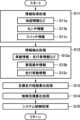
図2に示すように、ECU10は、入力処理部10a、周辺物標検出部10b、目標走行経路算出部10c、運転操作判断部10e、及び制御目標算出部10fとして機能する単一のCPU又はプロセッサを備えている。なお、本実施形態では、単一のCPUが複数の上記機能を実行するように構成されているが、これに限らず、複数のCPUがこれら機能を実行するように構成することができる。 As shown in FIG. 2, the
入力処理部10aは、車載カメラ21を含む種々のセンサ/スイッチ群、及び運転者操作部35から入力された入力情報を処理するように構成されている。この入力処理部10aは、走行路面を撮像したカメラ21の画像を解析し、車両1が走行している走行車線(車線の両側の区画線)を検出する画像解析部として機能する。 The
周辺物標検出部10bは、ミリ波レーダ22、カメラ21等からの入力情報に基づいて周辺物標を検出するように構成されている。
目標走行経路算出部10cは、ミリ波レーダ22、車載カメラ21、センサ群等からの入力情報に基づいて車両の目標走行経路を算出するように構成されている。The peripheral
The target travel
運転操作判断部10eは、運転支援制御として自動速度制御及び/又は自動操舵制御が実行されているときに、乗員がアクセルペダル,ブレーキペダル,又はステアリングホイールを操作した場合、乗員による操作を優先して、乗員による操作に応じた要求信号を制御システム31~33へ出力するように構成されている。すなわち、運転操作判断部10eにより、乗員は、自動的な運転支援制御をオーバーライドして、自らが運転操作を行うことが可能である。 When an occupant operates an accelerator pedal, a brake pedal, or a steering wheel while automatic speed control and/or automatic steering control is being executed as driving support control, the driving
制御目標算出部10fは、目標走行経路算出部10cによって算出された目標走行経路を補正して、補正走行経路を算出し、この補正走行経路に基づいて制御システム31~33へ要求信号を出力するように構成されている。 The control
例えば、制御目標算出部10fは、周辺物標検出部10bによって回避すべき周辺物標が検出された場合に、目標走行経路を補正して補正走行経路を算出する。また、制御目標算出部10fは、運転支援モードの変更によって目標走行経路自体が変更になった場合にも、新たな目標走行経路を補正して補正走行経路を算出する。車両1は、この補正走行経路を走行することにより、新たな目標走行経路へ合流する。すなわち、この場合の補正走行経路は、現在の車両挙動(舵角,加速度等)を新たな目標走行経路における車両挙動に適合させるための遷移的な経路である。 For example, when a peripheral target to be avoided is detected by the peripheral
制御目標算出部10fは、補正走行経路を算出するため、所定の評価関数を用いる。制御目標算出部10fは、目標走行経路を基準として評価関数を用いて複数の候補走行経路を評価し、所定の制約条件(又は、拘束条件)を満足するように最適化された1つの補正走行経路を算出する。また、本実施形態においては、評価関数及び制約条件は、選択されている運転支援モードや周辺物標等に基づいて、適宜設定される。 The control
ECU10は、制御目標算出部10fによって決定された最適な補正走行経路を走行すべく、少なくともエンジン制御システム31,ブレーキ制御システム32,又はステアリング制御システム33のいずれか1つ又は複数に対する要求信号を生成し、出力する。 The
次に、本実施形態による車両制御装置100が備える運転支援モードについて説明する。本実施形態では、運転支援モードとして、5つのモード(レーンキープ制御モード、先行車追従モード、自動速度制御モード、速度制限モード、基本制御モード)が備えられている。 Next, the driving support mode included in the
<レーンキープ制御モード>
レーンキープ制御モードは、車両1が車線の中央付近を走行するようにステアリング制御するモードであり、車両制御装置100による自動的なステアリング制御、速度制御(エンジン制御、ブレーキ制御)を伴う。<Lane keep control mode>
The lane keep control mode is a mode in which steering is controlled so that the
本実施形態では、レーンキープ制御モードの選択時(すなわち、LASスイッチ36dが操作又は押下されている状態)において、走行車線の車線両端部の検出の可否に応じて、異なる制御が行われる。すなわち、車線両端部の検出中、ECU10は、車両1が走行車線の中央付近を走行するようにステアリング制御及び速度制御を行う。しかしながら、車線両端部が検出されない場合、運転支援モードは、基本制御モード(オフモード)に切り替えられる。基本制御モードでは、運転者がステアリング操作,アクセル操作及びブレーキ操作を行う。 In this embodiment, when the lane keep control mode is selected (that is, when the
なお、車線両端部とは、車両1が走行する車線の両端部(白線等の区画線,道路端,縁石,中央分離帯,ガードレール等)であり、隣接する車線や歩道等との境界である。ECU10は、この車線両端部を車載カメラ21より撮像された画像データから検出する。また、ナビゲーションシステム30の地図情報から車線両端部を検出してもよい。 Note that both lane ends are the ends of the lane in which the
<先行車追従モード>
先行車追従モードは、基本的に、車両1と先行車との間に車速に応じた所定の車間距離又は車間時間を維持しつつ、先行車の走行軌跡を車両1に追従走行させるモードであり、車両制御装置100による自動的なステアリング制御,速度制御(エンジン制御,ブレーキ制御)を伴う。<Leading vehicle following mode>
The preceding vehicle following mode is basically a mode in which the
本実施形態では、ECU10は、車載カメラ21による画像データ及びミリ波レーダ22による測定データにより、先行車を検出する。具体的には、車載カメラ21による画像データにより前方を走行する他車両を走行車として検出する。更に、本実施形態では、ミリ波レーダ22による測定データにより、車両1と他車両との車間距離が所定距離(例えば、400~500m)以下である場合に、当該他車両が先行車として検出される。なお、代替的に、車載カメラ21及び/又はミリ波レーダ22が先行車を検出して、先行車の位置等の先行車情報をECU10へ出力してもよい。 In this embodiment, the
本実施形態では、先行車追従モードの選択時(すなわち、TJAスイッチ36bが操作又は押下されている状態)において、先行車の検出の可否に応じて、異なる制御が行われる。すなわち、先行車の検出中は、ECU10は、車両1が先行車を追従走行するようにステアリング制御及び速度制御を行う。しかしながら、先行車が検出されない間は、ECU10は、車両1が設定車速(一定速度)を目標速度として走行するように速度制御を行い、運転者がステアリング操作を行う。なお、設定車速は、例えば、車速設定スイッチ37bによって設定することができる。または、代替的に、先行車が検出されない間は、運転支援モードは、基本制御モード(オフモード)に切り替えられる。 In this embodiment, when the preceding vehicle following mode is selected (that is, the
また、代替的な先行車追従モードにおいて、車線両端部及び先行車の検出の可否に応じて、異なる制御が行われるように構成してもよい。例えば、代替的な先行車追従モードでは、車線両端部及び先行車が検出されている場合、ECU10は、車両1が先行車の走行軌跡を追従するのではなく、先行車との所定の車間距離を維持しながら、車両1が走行車線の中央付近を走行するようにステアリング制御及び速度制御を行う。一方、先行車は検出されているが、車線両端部は検出されていない場合は、ECU10は、車両1が先行車の走行軌跡を追従走行するようにステアリング制御及び速度制御を行う。さらに、車線両端部は検出されているが、先行車は検出されていない場合、ECU10は、車両1が走行車線の中央付近を設定車速で走行するようにステアリング制御及び速度制御を行う。さらに、先行車も車線両端部も検出されていない場合、ECU10は、車両1は設定車速で走行するように速度制御を行い、運転者がステアリング操作を行う。 Further, in the alternative preceding vehicle following mode, different control may be performed depending on whether or not a preceding vehicle can be detected at both ends of the lane. For example, in the alternative preceding vehicle following mode, when both ends of the lane and the preceding vehicle are detected, the
<自動速度制御モード>
また、自動速度制御モードは、車速設定スイッチ37bを使用して運転者によって予め設定された所定の設定車速(一定速度)を目標速度として維持するように速度制御するモードであり、車両制御装置100による自動的な速度制御(エンジン制御,ブレーキ制御)を伴うが、ステアリング制御は行われない。この自動速度制御モードでは、車両1は、設定車速を維持するように走行するが、運転者によるアクセルペダルの踏み込みにより設定車速を超えて増速され得る。また、運転者がブレーキ操作を行った場合には、運転者の意思が優先され、設定車速から減速される。また、先行車に追いついた場合には、車速に応じた車間距離又は車間時間を維持しながら先行車に追従するように速度制御され、先行車が存在しなくなると、再び設定車速に復帰するように速度制御される。<Automatic speed control mode>
Further, the automatic speed control mode is a mode in which speed control is performed so as to maintain a predetermined set vehicle speed (constant speed) set in advance by the driver using the vehicle
<速度制限モード>
また、速度制限モードは、車両1の車速が速度標識による制限速度又は運転者によって設定された設定車速を超えないように速度制御するモードであり、車両制御装置100による自動的な速度制御(エンジン制御)を伴うが、ステアリング制御は行われない。制限速度は、車載カメラ21により撮像された速度標識や路面上の速度表示の画像データをECU10が画像認識処理することにより特定してもよいし、外部からの無線通信により受信してもよい。速度制限モードでは、運転者が制限速度を超えるようにアクセルペダルを踏み込んだ場合であっても、車両1は制限速度までしか増速されない。<Speed limit mode>
In addition, the speed limit mode is a mode in which the speed of the
<基本制御モード>
基本制御モードは、運転者操作部35により、何れの運転支援モードも選択されていないときのモード(オフモード)であり、車両制御装置100による自動的なステアリング制御及び速度制御は行われない。<Basic control mode>
The basic control mode is a mode (off mode) when no driving support mode is selected by the
次に、本実施形態による車両制御装置100により計算される目標走行経路について説明する。本実施形態では、ECU10に備えられた目標走行経路算出部10cが、以下の第1走行経路R1~第3走行経路R3を時間的に繰返し計算するように構成されている(例えば、0.1秒毎)。本実施形態では、ECU10は、センサ等の情報に基づいて、現時点から所定期間(例えば、3秒)が経過するまでの間の走行経路を計算する。走行経路Rx(x=1,2,3)は、所定時間毎(例えば、0.3秒毎)に設定される走行経路上の車両1の目標位置(Px_k)及び目標速度(Vx_k)により特定される(k=0,1,2,・・・,n)。更に、各目標位置において、目標速度以外に複数の変数(加速度、ジャーク、ヨーレート、舵角、車両角度等)について目標値が特定される。 Next, the target travel route calculated by the
なお、第1走行経路~第3走行経路は、車両1が走行する走行路上又は走行路周辺の物標(駐車車両、歩行者等の障害物)に関する周辺物標の検出情報を考慮せずに、走行路の形状,先行車の走行軌跡,車両1の走行挙動,及び設定車速に基づいて計算される。このように、本実施形態では、周辺物標の情報が計算に考慮されないので、これら複数の走行経路の全体的な計算負荷を低く抑えることができる。 Note that the first to third travel routes are determined without taking into account detection information of peripheral targets on the travel road on which the
(第1走行経路)
第1走行経路R1は、道路形状に即して車両1に走行車線内の走行を維持させるように所定期間分だけ設定される。詳しくは、第1走行経路R1は、原則的に、車線の中央付近の走行を維持するように設定される。(First driving route)
The first travel route R1 is set for a predetermined period of time in accordance with the road shape so that the
目標走行経路算出部10cは、車載カメラ21により撮像された車両1の周囲の画像データの画像認識処理を実行し、車線両端部を検出する。車線両端部は、上述のように、区画線(白線等)や路肩等である。目標走行経路算出部10cは、車線両端部の幅方向の中央部を車両1の幅方向中央部(例えば、重心位置)が通過するように、第1走行経路R1の複数の目標位置P1_kを設定する。また、第1走行経路R1の各目標位置P1_kにおける目標速度V1_kは、原則的に、運転者が運転者操作部35の車速設定スイッチ37bによって設定した速度、又は車両制御装置100によって予め設定された所定の設定車速(一定速度)に設定される。 The target travel
(第2走行経路)
第2走行経路R2は、先行車の走行軌跡を追従するように所定期間分だけ設定される。目標走行経路算出部10cは、車載カメラ21による画像データ,ミリ波レーダ22による測定データ,車速センサ23による車両1の車速に基づいて先行車情報(先行車の位置,速度,加速度等)を取得し、先行車情報に基づいて、将来の所定期間にわたる先行車の走行挙動を推定又は予測する。具体的には、目標走行経路算出部10cは、先行車の予測走行挙動として、先行車が現在の走行挙動を維持しながら現在から所定期間後まで走行すると仮定する。(Second driving route)
The second travel route R2 is set for a predetermined period of time so as to follow the travel trajectory of the preceding vehicle. The target driving
そして、目標走行経路算出部10cは、先行車の予測走行挙動に基づいて、車両1が先行車に対して、先行車の後方位置において、車両1の速度に応じた車間距離(実際は、先行車との車間時間)を維持するように、第2走行経路R2(目標位置P2_k、目標速度V2_k)を計算する。 Then, the target travel
(第3走行経路)
第3走行経路R3は、運転者による車両1の現在の運転状態に基づいて所定期間分だけ設定される。即ち、第3走行経路R3は、車両1の現在の走行挙動又は車両運動から推定される位置及び速度に基づいて設定される。(Third driving route)
The third travel route R3 is set for a predetermined period of time based on the current driving state of the
目標走行経路算出部10cは、車両1の速度,ヨーレートに基づいて、所定期間分の第3走行経路R3を計算する。具体的には、第3走行経路R3は、車両1が現在の速度V及びヨーレートφを維持しながら、旋回半径R(=V/φ)で規定される円弧経路を定常円旋回するように計算される。よって、第3走行経路R3の目標速度V3_kは、現在の速度Vに設定され、目標位置P3_kは、円弧経路上を車両1が速度Vで走行した場合における所定時間毎の通過位置に設定される。 The target travel
次に、本実施形態による車両制御装置100における運転支援モードと走行経路との関係について説明する。本実施形態では、運転者が運転者操作部35を操作して1つの運転支援モードを選択すると、選択された運転支援モードに応じて第1~第3走行経路のうちの1つが目標走行経路として選択されるように構成されている。 Next, the relationship between the driving support mode and the travel route in the
レーンキープ制御モードの選択時には、車線両端部が検出されていると、第1走行経路が選択される。この場合、車速設定スイッチ37bによって設定された設定車速が目標速度となる。
また、先行車追従モードの選択時には、先行車が検出された場合、第2走行経路が選択される。この場合、目標速度は、先行車の車速に応じて設定される。また、先行車追従モードの選択時において、先行車が検出されない場合、車線両端部の検出の可否に応じて、第1又は第3走行経路が選択され、設定車速が目標速度となる。When the lane keep control mode is selected, if both ends of the lane are detected, the first travel route is selected. In this case, the set vehicle speed set by the vehicle
Furthermore, when the preceding vehicle following mode is selected, if a preceding vehicle is detected, the second travel route is selected. In this case, the target speed is set according to the vehicle speed of the preceding vehicle. Further, when the preceding vehicle following mode is selected, if the preceding vehicle is not detected, the first or third traveling route is selected depending on whether both ends of the lane can be detected, and the set vehicle speed becomes the target speed.
また、自動速度制御モードの選択時には、第3走行経路が選択される。自動速度制御モードは、上述のように速度制御を自動的に実行するモードであり、車速設定スイッチ37bによって設定された設定車速が目標速度となる。また、運転者によるステアリングホイールの操作に基づいてステアリング制御が実行される。 Furthermore, when the automatic speed control mode is selected, the third travel route is selected. The automatic speed control mode is a mode in which speed control is automatically executed as described above, and the set vehicle speed set by the vehicle
また、速度制限モードの選択時にも第3走行経路が選択される。速度制限モードも、上述のように速度制御を自動的に実行するモードであり、目標速度は、制限速度以下の範囲で、運転者によるアクセルペダルの踏み込み量に応じて設定される。また、運転者によるステアリングホイールの操作に基づいてステアリング制御が実行される。 Further, the third travel route is also selected when the speed limit mode is selected. The speed limit mode is also a mode in which speed control is automatically executed as described above, and the target speed is set in a range below the speed limit according to the amount of depression of the accelerator pedal by the driver. Furthermore, steering control is executed based on the driver's operation of the steering wheel.
また、基本制御モード(オフモード)の選択時には、第3走行経路が選択される。基本制御モードは、基本的に、速度制限モードにおいて制限速度が設定されない状態と同様である。 Furthermore, when the basic control mode (off mode) is selected, the third travel route is selected. The basic control mode is basically the same as the speed limit mode in which no speed limit is set.
次に、図3~図5を参照して、本実施形態によるECU10の制御目標算出部10fにおいて実行される制御目標算出処理について説明する。図3は制御目標算出処理の説明図、図4は補正走行経路の説明図、図5は車両モデルの説明図である。本実施形態において、制御目標算出処理には、走行経路補正処理が含まれる。 Next, the control target calculation process executed in the control
図3及び図4に示すように、制御目標算出部10fは、目標走行経路Rを外部環境(障害物3等)や運転支援モードの変更に応じて補正して、補正走行経路Rcを算出する。そして、制御目標算出部10fは、車両1がこの補正走行経路Rcを走行するための所定の制御量の制御目標値(加速度目標、舵角目標)を計算し、制御目標に基づいて車両1の制御システムへ要求信号を出力する。なお、図4には、所定期間(例えば、3秒)にわたる例示的な目標走行経路R,補正走行経路Rcが示されている。各経路R,Rcには、それぞれ所定時間毎(例えば、0.3秒毎)の目標位置P,補正目標位置Pcが示されている。 As shown in FIGS. 3 and 4, the control
具体的には、制御目標算出部10fは、センサ/スイッチ群から各種情報を受け取り、目標走行経路算出部10cから目標走行経路Rを受け取り、周辺物標検出部10bから周辺物標に関する情報を受け取る。制御目標算出部10fは、これらの情報に基づいて、制約条件(周辺物標との衝突回避等)を満足しつつ、目標走行経路Rからの逸脱量が小さくなるように最適化された補正走行経路Rcをモデル予測制御を用いて計算する。すなわち、本実施形態では、制御目標算出部10fは、制約条件下で(又は拘束条件下で)所定の評価関数Jの評価値を最小にするという最適化問題を解くように構成されたソルバーを含む。このため、制御目標算出部10fは、最適化計算部11aとモデル予測部11bを備えている。 Specifically, the control
本実施形態では、概略的には、最適化計算部11aは、車両1の現在の挙動(速度、位置、加速度、舵角等)に基づいて、制約条件(障害物等)を回避するような候補補正走行経路を設定し、候補補正走行経路上の各候補目標位置での物理量(加速度、舵角)を入力値としてモデル予測部11bへ与える。モデル予測部11bは、入力値を車両モデルに適用することにより、候補補正走行経路上での車両1の挙動を計算し、候補補正走行経路上の各候補目標位置を特定すると共に、車両挙動に基づく種々の物理量を最適化計算部11aへフィードバックする。各候補目標位置は、隣り合う候補目標位置間での移動距離を積算していくことにより算出される。 In this embodiment, roughly speaking, the
車両モデルは、車両1の物理的な運動を規定するものであり、以下の運動方程式で記述される。この車両モデルは、本例では図5に示す2輪モデルである。車両モデルにより車両1の物理的な運動が規定される。 The vehicle model defines the physical motion of the


図5及び式(1)、(2)中、mは車両1の質量、Iは車両1のヨーイング慣性モーメント、lはホイールベース、lfは車両重心点と前車軸間の距離、lrは車両重心点と後車軸間の距離、Kfは前輪1輪あたりのタイヤコーナリングパワー、Krは後輪1輪あたりのタイヤコーナリングパワー、Vは車両1の車速、δは前輪の実舵角、βは車両重心点の横すべり角、rは車両1のヨー角速度、θは車両1のヨー角、yは絶対空間に対する車両1の横変位、tは時間である。In Figure 5 and equations (1) and (2), m is the mass of
最適化計算部11aは、候補補正走行経路上での車両1の挙動を表すフィードバックに基づいて評価関数Jを用いて、候補補正走行経路を評価する。本実施形態では、評価関数Jは、補正走行経路の評価に関する評価項JEと、制約条件に関する制約項JCとを含む。評価項JEは、複数の評価ファクタを有する。また、制約項JCは複数の制約ファクタを有する。制御目標算出部10fは、実行中の運転支援モード及びセンサ情報等に応じて異なるように評価関数Jを設定する。 The
複数の評価ファクタは、目標位置Pでの車両1の挙動を表す複数の物理量(例えば、速度(縦方向及び横方向)、加速度(縦方向及び横方向)、ジャーク(縦方向及び横方向)、ヨーレート、車線中心に対する横位置、車両角度、舵角、舵角速度、その他ソフト制約)にそれぞれ対応して設定されている。評価ファクタには、目標走行経路と補正走行経路の物理量の差が小さいほど評価が高くなる第1評価ファクタと、物理量自体の大きさが小さいほど評価が高くなる第2評価ファクタが含まれる。本実施形態では、評価値が小さな値となるほど、評価が高くなる。 The plurality of evaluation factors include a plurality of physical quantities representing the behavior of the
第1評価ファクタは、目標走行経路と補正走行経路の差を最小化するための評価ファクタであり、第1評価ファクタの物理量は、例えば、速度(縦方向及び横方向)、横位置等である。一方、第2評価ファクタは、所定の物理量を最小化するための評価ファクタであり、第2評価ファクタの物理量は、例えば、加速度(縦方向及び横方向)、ジャーク(縦方向及び横方向)、舵角、舵角速度等である。 The first evaluation factor is an evaluation factor for minimizing the difference between the target travel route and the corrected travel route, and the physical quantities of the first evaluation factor are, for example, speed (vertical and horizontal directions), lateral position, etc. . On the other hand, the second evaluation factor is an evaluation factor for minimizing a predetermined physical quantity, and the physical quantities of the second evaluation factor are, for example, acceleration (vertical and lateral directions), jerk (vertical and lateral directions), These include the rudder angle and rudder angular speed.
また、複数の制約ファクタは、複数の物理量にそれぞれ対応して設定されている。制約ファクタは、対応する物理量に対して規定された制限範囲(下限値~上限値)をその物理量が超えた量に応じて、ペナルティ値として見積もられる。よって、超過量が大きいほど、ペナルティ値は大きくなる(すなわち、結果的に、評価値は大きくなる)。 Further, the plurality of constraint factors are set corresponding to the plurality of physical quantities, respectively. The constraint factor is estimated as a penalty value according to the amount by which the physical quantity exceeds the limit range (lower limit to upper limit) defined for the corresponding physical quantity. Therefore, the larger the excess amount, the larger the penalty value (that is, the larger the evaluation value becomes).
例えば、速度(縦方向及び横方向)、加速度(縦方向及び横方向)、ジャーク(縦方向及び横方向)、舵角、舵角速度、ヨーレートを含む複数の物理量には、それぞれ原則的に固定された制限範囲が規定されている。しかしながら、固定の制限範囲よりも狭い範囲に制限範囲が変更される場合がある。例えば、下記で説明する速度分布領域(図6参照)が適用される場合には、車両1の位置に応じて物標3に対する速度の制限範囲が変更される。 For example, multiple physical quantities including speed (longitudinal and lateral), acceleration (longitudinal and lateral), jerk (longitudinal and lateral), steering angle, steering angle velocity, and yaw rate are each fixed in principle. A limited range is specified. However, the limit range may be changed to a narrower range than the fixed limit range. For example, when the speed distribution area described below (see FIG. 6) is applied, the speed limit range with respect to the
評価関数J(=JE+JC)は、以下の式で記述される。


評価項JEについて、式中、Wk(Xk-Xrefk)2は評価ファクタ、Xkは候補補正走行経路の物理量、Xrefkは目標走行経路の物理量又は0(ゼロ値)、Wkは評価ファクタの重み係数(例えば、0≦Wk≦1)である(但し、k=1~n)。したがって、本実施形態の評価項JEは、n個の評価ファクタの物理量について、候補補正走行経路の物理量から目標走行経路の物理量(目標走行経路との差を最小化する評価ファクタの場合)又はゼロ値(物理量自体を最小化する評価ファクタの場合)を差し引いた差分の2乗の和を重み付けして、所定期間(例えば、N=3秒)の走行経路長にわたって合計した値に相当する。なお、重み係数Wkは、各運転支援モードに応じて異なって設定される。Regarding the evaluation term JE, in the formula, Wk (Xk - Xrefk)2 is the evaluation factor, Xk is the physical quantity of the candidate corrected travel route, Xrefk is the physical quantity of the target travel route or 0 (zero value), and Wk is the weighting coefficient of the evaluation factor ( For example, 0≦Wk≦1) (where k=1 to n). Therefore, the evaluation term JE of the present embodiment is calculated from the physical quantities of the candidate corrected travel route to the physical quantity of the target travel route (in the case of an evaluation factor that minimizes the difference from the target travel route) or zero for the physical quantities of the n evaluation factors. It corresponds to the value obtained by weighting the sum of the squares of the differences obtained by subtracting the value (in the case of an evaluation factor that minimizes the physical quantity itself) and summing the sum over the travel route length for a predetermined period (for example, N=3 seconds). Note that the weighting coefficient Wk is set differently depending on each driving support mode.
一方、制約項JCは、複数の物理量の制限範囲からの超過量に応じた評価値の合計値を、所定期間(例えば、N=3秒)の走行経路長にわたって合計した値に相当する。各評価値は、例えば、超過量を2乗した値に所定の重み係数Wを乗じた値とすることができる。なお、所定の物理量の制限範囲は、周辺物標等に応じて変動し得る。 On the other hand, the constraint term JC corresponds to a value obtained by summing the total value of evaluation values according to the amount of excess of a plurality of physical quantities from the limit range over the travel route length for a predetermined period (for example, N=3 seconds). Each evaluation value can be, for example, a value obtained by multiplying a value obtained by squaring the amount of excess by a predetermined weighting coefficient W. Note that the limit range of the predetermined physical quantity may vary depending on surrounding targets and the like.
本実施形態では、評価関数Jは、制約項JCが組み込まれたラグランジュ関数である。よって、最適化計算部11aは、無制約の最適化問題を解くように構成されており、良好な収束性で最適解を導出可能である。仮に評価関数Jが制約項JCを含まない場合、モデル予測部11bからのフィードバックが制約条件を満足しないと、そのフィードバックは最適化問題の収束性に何ら寄与しない。この場合、最適解が所定計算時間内に得られないおそれがある。 In this embodiment, the evaluation function J is a Lagrangian function incorporating a constraint term JC. Therefore, the
さらに、本実施形態では、フィードバックが制約条件を完全には満足しない場合であっても、最適化計算部11aは、その候補補正走行経路を、制約条件を考慮して評価関数Jにより評価することができる。これにより、本実施形態では、収束性を向上させることができる。例えば、センサ情報等のノイズ誤差や、道路環境の評価に対する誤差や、モデル関数に起因する誤差等により、制約条件をわずかに超えるような候補補正走行経路を確実に評価することができる。ただし、本実施形態では、制約項JCの重み係数を大きな値に設定することにより、制約項JCを制約条件として確実に機能させることができる。 Furthermore, in the present embodiment, even if the feedback does not completely satisfy the constraint conditions, the
本実施形態では、最適化計算部11aは、モデル予測部11bからのフィードバックに基づいて、評価関数Jを用いて候補補正走行経路についての評価値を算出する。最適化計算部11aは、評価値に応じて、新たな候補目標走行経路を設定し、この新たな候補補正走行経路に基づいて、修正した入力値をモデル予測部11bへ与える。本実施形態では、このような最適化計算部11aとモデル予測部11bとの間でのフィードバックが複数回繰り返されることにより、評価関数Jの評価値が最小化(又は、最適化)された補正走行経路Rcが算出される。なお、フィードバックの最大繰り返し回数は、所定回数に制限されてもよい。 In this embodiment, the
次に、図6~図7を参照して、本実施形態による障害物回避処理について説明する。図6は目標走行経路の補正による障害物回避の説明図、図7は障害物を回避する際の障害物と車両との間のすれ違い速度の許容上限値とクリアランスとの関係を示す説明図である。図6では、車両1は走行路(車線)7上を走行しており、走行中又は停車中の車両3とすれ違って、車両3を追い抜こうとしている。 Next, obstacle avoidance processing according to this embodiment will be described with reference to FIGS. 6 and 7. FIG. 6 is an explanatory diagram of obstacle avoidance by correcting the target driving route, and FIG. 7 is an explanatory diagram showing the relationship between the allowable upper limit value of the passing speed between the obstacle and the vehicle when avoiding the obstacle and the clearance. be. In FIG. 6, the
一般に、道路上又は道路付近の障害物(例えば、先行車、駐車車両、歩行者等)とすれ違うとき(又は追い抜くとき)、車両1の運転者は、進行方向に対して直交する横方向において、車両1と障害物との間に所定のクリアランス又は間隔(横方向距離)を保ち、且つ、車両1の運転者が安全と感じる速度に減速する。具体的には、先行車が急に進路変更したり、障害物の死角から歩行者が出てきたり、駐車車両のドアが開いたりするといった危険を回避するため、クリアランスが小さいほど、障害物に対する相対速度は小さくされる。 Generally, when passing (or overtaking) an obstacle on or near the road (e.g., a preceding vehicle, a parked vehicle, a pedestrian, etc.), the driver of the
また、一般に、後方から先行車に近づいているとき、車両1の運転者は、進行方向に沿った車間距離(縦方向距離)に応じて速度(相対速度)を調整する。具体的には、車間距離が大きいときは、接近速度(相対速度)が大きく維持されるが、車間距離が小さくなると、接近速度は低速にされる。そして、所定の車間距離で両車両の間の相対速度はゼロとなる。これは、先行車が駐車車両であっても同様である。 Generally, when approaching a preceding vehicle from behind, the driver of the
このように、運転者は、障害物と車両1との間の距離(横方向距離及び縦方向距離を含む)と相対速度との関係を考慮しながら、危険がないように車両1を運転している。 In this way, the driver can drive the
そこで、本実施形態では、図6に示すように、車両1は、車両1から検知される障害物(例えば、駐車車両3)に対して、障害物の周囲に(横方向領域、後方領域、及び前方領域にわたって)又は少なくとも障害物と車両1との間に、車両1の進行方向における相対速度についての許容上限値を規定する2次元分布(速度分布領域40)を設定するように構成されている。速度分布領域40では、障害物の周囲の各点において、相対速度の許容上限値Vlimが設定されている。Therefore, in this embodiment, as shown in FIG. and the forward area) or at least between the obstacle and the
図6から分かるように、速度分布領域40は、原則的に、障害物からの横方向距離及び縦方向距離が小さくなるほど(障害物に近づくほど)、相対速度の許容上限値が小さくなるように設定される。また、図6では、理解の容易のため、同じ許容上限値を有する点を連結した等相対速度線が示されている。等相対速度線a,b,c,dは、それぞれ許容上限値Vlimが0km/h,20km/h,40km/h,60km/hに相当する。本例では、各等相対速度領域は、略矩形に設定されている。As can be seen from FIG. 6, the
本実施形態では、すべての運転支援モードにおいて、障害物に対する車両1の相対速度が速度分布領域40内の許容上限値Vlimを超えることがないように目標走行経路の補正が実施される。すなわち、速度分布領域40が、車両1の速度に対する制約条件となる。具体的には、制御目標算出部10fは、周辺物標検出部10bによって回避すべき障害物(周辺物標)が検出されると、障害物に対して速度分布領域40を設定する。そして、制御目標算出部10fは、速度分布領域40により規定される許容上限値Vlimを超えることがないように、目標走行経路算出部10cによって算出された目標走行経路Rを補正して、補正走行経路Rcを算出する。図6には、例示的な補正走行経路Rc1,Rc2,Rc3が示されている。In this embodiment, in all driving support modes, the target travel route is corrected so that the relative speed of the
なお、速度分布領域40は、必ずしも障害物の全周にわたって設定されなくてもよく、少なくとも障害物の後方、及び、車両1が存在する障害物の横方向の一方側(図6では、車両3の右側領域)に設定されればよい。 Note that the
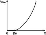
図7に示すように、車両1がある絶対速度で走行するときにおいて、障害物の横方向に設定される許容上限値Vlimは、クリアランスXがD0(安全距離)までは0(ゼロ)km/hであり、D0以上で2次関数的に増加する(Vlim=k(X-D0)2。ただし、X≧D0)。即ち、安全確保のため、クリアランスXがD0以下では車両1は相対速度がゼロとなる。一方、クリアランスXがD0以上では、クリアランスが大きくなるほど、車両1は大きな相対速度ですれ違うことが許容される。As shown in FIG. 7, when the
図7の例では、障害物の横方向における許容上限値は、Vlim=f(X)=k(X-D0)2で定義されている。なお、kは、Xに対するVlimの変化度合いに関連するゲイン係数であり、障害物の種類等に依存して設定される。また、D0も障害物の種類等に依存して設定される。In the example of FIG. 7, the allowable upper limit value of the obstacle in the lateral direction is defined as Vlim =f(X)=k(X-D0 )2 . Note that k is a gain coefficient related to the degree of change of Vlim with respect to X, and is set depending on the type of obstacle and the like. Further, D0 is also set depending on the type of obstacle and the like.
なお、本実施形態では、VlimがXの2次関数となるように定義されているが、これに限らず、他の関数(例えば、一次関数等)で定義されてもよい。また、図7を参照して、障害物の横方向の許容上限値Vlimについて説明したが、障害物の縦方向を含むすべての径方向について同様に設定することができる。その際、係数k、安全距離D0は、障害物からの方向に応じて設定することができる。Note that in this embodiment, Vlim is defined as a quadratic function of X, but is not limited to this and may be defined as another function (for example, a linear function, etc.). Further, although the permissible upper limit Vlim in the horizontal direction of the obstacle has been described with reference to FIG. 7, it can be similarly set in all radial directions including the vertical direction of the obstacle. At this time, the coefficient k and the safety distance D0 can be set depending on the direction from the obstacle.
なお、速度分布領域40は、種々のパラメータに基づいて設定することが可能である。パラメータとして、例えば、車両1と障害物の相対速度、障害物の種類、車両1の進行方向、障害物の移動方向及び移動速度、障害物の長さ、車両1の絶対速度等を考慮することができる。即ち、これらのパラメータに基づいて、係数k及び安全距離D0を選択することができる。Note that the
また、本実施形態において、障害物は、車両,歩行者,自転車,崖,溝,穴,落下物等を含む。更に、車両は、自動車,トラック,自動二輪で区別可能である。歩行者は、大人,子供,集団で区別可能である。 In the present embodiment, obstacles include vehicles, pedestrians, bicycles, cliffs, grooves, holes, fallen objects, and the like. Furthermore, vehicles can be distinguished as cars, trucks, and motorcycles. Pedestrians can be distinguished as adults, children, and groups.
図6に示すように、車両1が走行路7上を走行しているとき、車両1のECU10に内蔵された周辺物標検出部10bは、車載カメラ21から画像データに基づいて障害物(車両3)を検出する。このとき、障害物の種類(この場合は、車両、歩行者)が特定される。 As shown in FIG. 6, when the
また、周辺物標検出部10bは、ミリ波レーダ22の測定データ及び車速センサ23の車速データに基づいて、車両1に対する障害物(車両3)の位置及び相対速度並びに絶対速度を算出する。なお、障害物の位置は、車両1の進行方向に沿ったx方向位置(縦方向距離)と、進行方向と直交する横方向に沿ったy方向位置(横方向距離)が含まれる。 Further, the surrounding
制御目標算出部10fは、検知したすべての障害物(図6の場合、車両3)について、それぞれ速度分布領域40を設定する。そして、制御目標算出部10fは、車両1の速度が速度分布領域40の許容上限値Vlimを超えないように目標走行経路Rの補正を行う。The control
即ち、目標走行経路Rを車両1が走行すると、ある目標位置において目標速度が速度分布領域40によって規定された許容上限値を超えてしまう場合には、目標位置を変更することなく目標速度を低下させるか(図6の経路Rc1)、目標速度を変更することなく目標速度が許容上限値を超えないように迂回経路上に目標位置を変更するか(図6の経路Rc3)、目標位置及び目標速度の両方が変更される(図6の経路Rc2)。 That is, when the
なお、一般的に、評価関数Jにおいて、舵角速度を最小化するための評価ファクタの重み係数が大きい場合に補正走行経路Rc1が算出され、前後方向の加速度を最小化するための評価ファクタの重み係数が大きい場合に補正走行経路Rc3が算出される。 Generally, in the evaluation function J, the corrected travel route Rc1 is calculated when the weighting coefficient of the evaluation factor for minimizing the steering angular velocity is large, and the weighting of the evaluation factor for minimizing the longitudinal acceleration is calculated. When the coefficient is large, a corrected travel route Rc3 is calculated.
例えば、図6は、計算されていた目標走行経路Rが、走行路7の幅方向の中央位置(目標位置)を60km/h(目標速度)で走行する経路であった場合を示している。この場合、前方に駐車車両3が障害物として存在するが、上述のように、目標走行経路Rの計算段階においては、計算負荷の低減のため、この障害物は考慮されていない。 For example, FIG. 6 shows a case where the calculated target travel route R is a route in which the vehicle travels at a widthwise center position (target position) of the
目標走行経路Rを走行すると、車両1は、速度分布領域40の等相対速度線d,c,c,dを順に横切ることになる。即ち、60km/hで走行する車両1が等相対速度線d(許容上限値Vlim=60km/h)の内側の領域に進入することになる。したがって、制御目標算出部10fは、目標走行経路Rの各目標位置における目標速度を許容上限値Vlim以下に制限するように目標走行経路Rを補正して、補正走行経路Rc1を生成する。即ち、補正走行経路Rc1では、各目標位置において目標速度が許容上限値Vlim以下となるように、車両3に接近するに連れて目標速度が徐々に40km/h未満に低下し、その後、車両3から遠ざかるに連れて目標速度が元の60km/hまで徐々に増加される。When the
また、補正走行経路Rc3は、目標走行経路Rの目標速度(60km/h)を変更せず、このため等相対速度線d(相対速度60km/hに相当)の外側を走行するように設定された経路である。制御目標算出部10fは、目標走行経路Rの目標速度を維持するため、目標位置が等相対速度線d上又はその外側に位置するように目標位置を変更するように目標走行経路Rを補正して、補正走行経路Rc3を生成する。したがって、補正走行経路Rc3の目標速度は、目標走行経路Rの目標速度であった60km/hに維持される。 In addition, the corrected travel route Rc3 does not change the target speed (60 km/h) of the target travel route R, and is therefore set to travel outside the constant relative speed line d (corresponding to a relative speed of 60 km/h). This is the route taken. In order to maintain the target speed of the target travel route R, the control
また、補正走行経路Rc2は、目標走行経路Rの目標位置及び目標速度の両方が変更された経路である。補正走行経路Rc2では、目標速度は、60km/hには維持されず、車両3に接近するに連れて徐々に低下し、その後、車両3から遠ざかるに連れて元の60km/hまで徐々に増加される。 Further, the corrected travel route Rc2 is a route in which both the target position and target speed of the target travel route R have been changed. In the corrected travel route Rc2, the target speed is not maintained at 60 km/h, but gradually decreases as it approaches the
補正走行経路Rc1のように、目標走行経路Rの目標位置を変更せず、目標速度のみを変更する補正は、速度制御を伴うが、ステアリング制御を伴わない運転支援モードに適用することができる(例えば、自動速度制御モード、速度制限モード、基本制御モード)。
また、補正走行経路Rc3のように、目標走行経路Rの目標速度を変更せず、目標位置のみを変更する補正は、ステアリング制御を伴う運転支援モードに適用することができる(例えば、先行車追従モード)。
また、補正走行経路Rc2のように、目標走行経路Rの目標位置及び目標速度を共に変更する補正は、速度制御及びステアリング制御を伴う運転支援モードに適用することができる(例えば、先行車追従モード)。A correction that does not change the target position of the target travel route R and only changes the target speed, such as the corrected travel route Rc1, involves speed control but can be applied to a driving support mode that does not involve steering control ( For example, automatic speed control mode, speed limit mode, basic control mode).
In addition, a correction that does not change the target speed of the target travel route R and only changes the target position, such as the corrected travel route Rc3, can be applied to a driving support mode that involves steering control (for example, following a preceding vehicle mode).
In addition, correction that changes both the target position and target speed of the target travel route R, such as the corrected travel route Rc2, can be applied to a driving support mode that involves speed control and steering control (for example, a preceding vehicle following mode ).
次に、図8を参照して、本実施形態の車両制御装置100における運転支援制御の処理フローを説明する。図8は運転支援制御の処理フローである。
ECU10は、図8の処理フローを所定時間(例えば、0.1秒)ごとに繰り返して実行している。まず、ECU10(入力処理部10a)は、情報取得処理を実行する(S11)。情報取得処理において、ECU10は、測位システム29及びナビゲーションシステム30から、現在車両位置情報及び地図情報を取得し(S11a)、車載カメラ21,ミリ波レーダ22,車速センサ23,加速度センサ24,ヨーレートセンサ25,運転者操作部35等からセンサ情報を取得し(S11b)、舵角センサ26,アクセルセンサ27,ブレーキセンサ28等からスイッチ情報を取得する(S11c)。Next, with reference to FIG. 8, a processing flow of driving support control in the
The
次に、ECU10(入力処理部10a,周辺物標検出部10b)は、情報取得処理(S11)において取得した各種の情報を用いて所定の情報検出処理を実行する(S12)。情報検出処理において、ECU10は、現在車両位置情報及び地図情報並びにセンサ情報から、車両1の周囲及び前方エリアにおける走行路形状に関する走行路情報(直線区間及びカーブ区間の有無,各区間長さ,カーブ区間の曲率半径,車線幅,車線両端部位置,車線数,交差点の有無,カーブ曲率で規定される制限速度等)、走行規制情報(制限速度、赤信号等)、先行車情報(先行車の位置,速度,加速度等),周辺物標情報を検出する(S12a)。 Next, the ECU 10 (
また、ECU10は、スイッチ情報から、運転者による車両操作に関する車両操作情報(舵角,アクセルペダル踏み込み量,ブレーキペダル踏み込み量等)を検出し(S12b)、更に、スイッチ情報及びセンサ情報から、車両1の挙動に関する走行挙動情報(車速、縦加速度、横加速度、ヨーレート等)を検出する(S12c)。 The
次に、ECU10(目標走行経路算出部10c)は、計算により得られた情報に基づいて、目標走行経路算出処理を実行する(S13)。目標走行経路算出処理では、上述のように、第1走行経路R1,第2走行経路R2,及び第3走行経路R3が計算され、これらの中から、選択されている運転支援モードとセンサ情報(先行車、車線両端部等)に応じて、目標走行経路Rが選択される。 Next, the ECU 10 (target travel
次に、ECU10(制御目標算出部10f)は、目標走行経路R、周辺物標情報、各種のセンサ情報等に基づいて、制御目標算出処理を実行する(S14)。制御目標算出処理では、上述のように、補正走行経路Rcが算出され、この補正走行経路Rc上の各補正目標位置Pcにおける所定の制御量の制御目標(加速度目標、舵角目標)が生成される。 Next, the ECU 10 (control
最後に、ECU10(制御目標算出部10f)は、生成した補正走行経路Rcにおける制御目標に基づいて、システム制御処理を実行して(S15)、処理を終了する。システム制御処理では、補正走行経路Rcにおける制御目標に応じて、要求信号(エンジン要求信号,ブレーキ要求信号,ステアリング要求信号)が生成され、生成された要求信号が車両1の制御システム31~33へ出力される。 Finally, the ECU 10 (control
次に、図9A~図13を参照して、本実施形態の第2走行経路を算出する際の先行車の予測走行挙動について説明する。図9Aは比較例に係る先行車の予測走行挙動の説明図であり、図9Bは本実施形態による先行車の予測走行挙動の説明図である。図10A,図10Bは、それぞれ一般的に想定される車両の減速度の説明図である。図11~図13は、本実施形態の変形例による先行車の予測走行挙動の説明図である。 Next, with reference to FIGS. 9A to 13, the predicted driving behavior of the preceding vehicle when calculating the second driving route of this embodiment will be described. FIG. 9A is an explanatory diagram of the predicted driving behavior of the preceding vehicle according to the comparative example, and FIG. 9B is an explanatory diagram of the predicted traveling behavior of the preceding vehicle according to the present embodiment. FIGS. 10A and 10B are explanatory diagrams of generally assumed vehicle deceleration, respectively. 11 to 13 are explanatory diagrams of predicted driving behavior of a preceding vehicle according to a modification of the present embodiment.
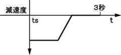
所定の予測期間Tpにわたる先行車の未来の走行挙動を予測して、この予測走行挙動に基づいて、先行車に追従する予測期間Tpにわたる目標走行経路Rを計算する際に、先行車の速度変化(例えば、減速)を考慮することが考えられる。この場合、一般的には、先行車の現在(t=ts)の走行挙動が予測期間Tp(ts~te)にわたって継続すると仮定される。例えば、図9Aに示すように、先行車の現在の減速度が値d0である場合、予測期間Tp(例えば、3秒)にわたって値d0が継続すると仮定される。なお、車両1が減速する場合、減速度(負の加速度)は正の値である(d0>0)。 When predicting the future driving behavior of the preceding vehicle over a predetermined prediction period Tp and calculating a target driving route R over the prediction period Tp for following the preceding vehicle based on this predicted driving behavior, changes in the speed of the preceding vehicle are calculated. (For example, deceleration) may be considered. In this case, it is generally assumed that the current (t=ts) driving behavior of the preceding vehicle continues over the prediction period Tp (ts to te). For example, as shown in FIG. 9A, when the current deceleration of the preceding vehicle is the value d0, it is assumed that the value d0 continues over the prediction period Tp (for example, 3 seconds). Note that when the
しかしながら、一般的にカーブへの進入前の減速や先行車の減速に合わせて減速する場合、運転者がブレーキペダルを長時間(例えば、3秒)にわたって踏み続けることはまれである。例えば、運転者は、典型的には、短時間(例えば、1秒程度)でブレーキ操作を終了するか(図10A参照)、短時間の大きな減速度のための第1のブレーキ操作後に必要に応じて小さな減速度のための第2のブレーキ操作をする(図10B参照)。 However, in general, when decelerating before entering a curve or decelerating in accordance with the deceleration of a preceding vehicle, it is rare for a driver to continue pressing the brake pedal for a long period of time (for example, 3 seconds). For example, the driver typically completes the brake application in a short period of time (e.g., on the order of 1 second) (see Figure 10A), or if necessary after the first brake application for a short period of large deceleration (see Figure 10A). A second brake operation for a small deceleration is performed accordingly (see FIG. 10B).
したがって、図9Aに示される先行車の予測走行挙動では、図10A,図10Bのような典型的な走行挙動と比べて、先行車の減速が過剰に見積もられている。このため、図9Aに示す予測走行挙動に基づいて算出された目標走行経路Rを車両1が走行すると、車両1は先行車よりも減速されるので、先行車と車両1との間の車間距離(又は車間時間)が大きくなってしまう。そして、その後に計算される目標走行経路Rは、大きくなった車間距離を元に戻すように算出されるので、車両1の挙動が不安定になってしまう。 Therefore, in the predicted driving behavior of the preceding vehicle shown in FIG. 9A, the deceleration of the preceding vehicle is overestimated compared to the typical driving behavior shown in FIGS. 10A and 10B. Therefore, when the
そこで、本実施形態では、ECU10(目標走行経路算出部10c)は、先行車情報に基づいて、先行車の減速を検出すると、時間経過と共に減速度が小さくなると予測して、目標走行経路Rを算出する。すなわち、本実施形態よる先行車の予測走行挙動では、先行車の減速度が、現在の値d0(d0>0)から、所定期間後に値d0よりも小さい値(d0よりもゼロに近い値)に変化するように設定される。 Therefore, in the present embodiment, when the ECU 10 (target travel
図9Bに示す本実施形態による予測走行挙動では、先行車の減速度が、時間と共に線形的に減少して、現在の値d0から予測期間Tp経過後にゼロとなるように設定される。すなわち、先行車の減速度は、予測期間Tpの始端(t=ts)において値d0(第1の減速度)に設定され、予測期間Tpの終端(t=te)において値d0よりも小さい値(第2の減速度)に設定される。このように予測走行挙動を設定することにより、先行車の減速を過剰に見積もることが抑制されると共に、先行車と車両1との間の車間距離又は車間時間の変動を抑制することができる。 In the predicted driving behavior according to the present embodiment shown in FIG. 9B, the deceleration of the preceding vehicle is set to decrease linearly with time and become zero after the prediction period Tp has elapsed from the current value d0. That is, the deceleration of the preceding vehicle is set to the value d0 (first deceleration) at the beginning of the prediction period Tp (t=ts), and is set to a value smaller than the value d0 at the end of the prediction period Tp (t=te). (second deceleration). By setting the predicted driving behavior in this way, it is possible to suppress excessive estimation of the deceleration of the preceding vehicle, and to suppress fluctuations in the inter-vehicle distance or inter-vehicle time between the preceding vehicle and the
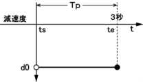
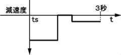
また、図11に示す本実施形態の変形例に係る先行車の予測走行挙動では、現在から閾値期間Tth1(0<Tth1<Tp)経過するまで(ts~t1)、先行車の減速度が現在の値d0(第1の減速度)に維持され、閾値期間Tth1経過後から予測期間Tp経過後まで(t1~te)、減速度が値d0よりも小さい値d1(第2の減速度)に維持される(d0>d1>0)。図11の例においても、予測期間Tpの終端(t=te)における先行車の減速度は、予測期間Tpの始端(t=ts)における減速度よりも小さな値に設定される。 In addition, in the predicted driving behavior of the preceding vehicle according to the modification of the present embodiment shown in FIG. 11, the deceleration of the preceding vehicle will be is maintained at the value d0 (first deceleration), and from after the threshold period Tth1 has elapsed until after the prediction period Tp has elapsed (t1 to te), the deceleration becomes a value d1 (second deceleration) smaller than the value d0. is maintained (d0>d1>0). Also in the example of FIG. 11, the deceleration of the preceding vehicle at the end of the prediction period Tp (t=te) is set to a smaller value than the deceleration at the beginning (t=ts) of the prediction period Tp.
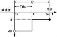
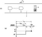
また、図12(A)に示すように、走行路7上において、先行車3の前方の所定距離以内(例えば、50m以内)に信号機5が検出され、この信号機5が「赤信号」であった場合、図11Aの予測走行挙動に代えて、図12(B)に示す予測走行挙動が用いられる。この状況では、前方の赤信号に起因して、先行車3において停止するために、より大きな制動力で通常よりも長い時間にわたってブレーキ操作が行われると予想される。よって、図12(B)では、閾値期間(ts~t2)が、通常のTth1よりも長いTth2に設定され(Tth1<Tth2<Tp)、且つ、閾値期間Tth2経過後(t2~te)の減速度が、通常の値d1よりも大きい値d2(第2の減速度)に設定される(0<d1<d2)。なお、図12(B)では、より長い閾値期間とより大きい減速度が用いられているが、いずれか一方のみでもよい。 Further, as shown in FIG. 12(A), a
また、図13(A)に示すように、走行路7上において、先行車3の前方の所定距離以内(例えば、50m以内)に所定曲率半径Rth以下の曲率半径R0を有するカーブ路7aが検出された場合、図11の予測走行挙動に代えて、図13(B)に示す予測走行挙動が用いられる。この状況では、前方のカーブ路7aに起因して行われる先行車3におけるブレーキ操作が、長期間にわたって継続される可能性は低いと予想される。よって、図13(B)では、所定の閾値期間Tth3が経過するまでは(ts~t3)、減速度が値d0に維持され、閾値期間Tth3経過後(t3~te)は減速度がゼロを含む通常の値d1よりも小さな値d3(第2の減速度)に設定される(0≦d3<d1)。また、カーブ路7aの曲率半径R0が小さいほど、及び、先行車3の速度が大きいほど、先行車におけるブレーキ操作の時間がより長くなると予想される。よって、カーブ路7aの曲率半径R0が小さいほど、及び/又は、先行車3の速度が大きいほど、閾値期間Tth3は、よりも長い期間に設定される。 Further, as shown in FIG. 13(A), a
次に、本発明の実施形態による車両制御装置100の作用について説明する。
本発明の実施形態の車両1の運転を支援するための車両制御装置100は、先行車3の予測走行挙動(例えば、図9B,図11~図13)に基づいて、先行車3に追従するための所定の予測期間Tpにわたる走行経路(目標走行経路R又は補正走行経路Rc)を算出する処理(S13)と、車両1が走行経路を走行するための車両1の制御目標値を算出する処理(S14)とを、予測期間Tpより短い所定の制御周期毎に繰り返し実行するように構成されており、先行車3が減速している場合、先行車3の現在の減速度d0を、予測期間Tpの始端(t=ts)における先行車3の第1の減速度に設定し、第1の減速度よりも小さい減速度(ゼロ,d1,d2,d3)を、予測期間Tpの終端(t=te)における先行車3の第2の減速度に設定し、予測期間Tpにおいて、先行車3の減速度が第1の減速度から第2の減速度に変化するように、先行車3の予測走行挙動を設定する。Next, the operation of the
The
このように構成された本実施形態では、先行車3の予想走行挙動に応じて車両1が先行車3に追従するように、予測期間Tpにわたる車両1の走行経路が算出され、この走行経路を走行するように車両1の制御目標値が算出される。本実施形態では、このような走行経路は、例えば、車両1と先行車3との車間距離又は車間時間が車両1の速度に応じて一定に維持されるように計算される。走行経路により、車両1は走行経路上の各目標点における目標位置と目標速度等が設定される。そして、本実施形態では、追従時に先行車3が減速した場合、先行車3の現在の減速度が維持されるとの予測に基づく先行車の予測走行挙動に代えて、典型的な車両のブレーキ操作に沿うような予測走行挙動が用いられる。すなわち、本実施形態では、先行車3の減速度が、予測期間Tpの始端における減速度よりも終端における減速度の方が小さく設定される。これにより、本実施形態では、先行車3に対して車両1の過剰な減速が抑制され、先行車3と車両1との間の車間距離又は車間時間の変動を抑制することができる。なお、仮に先行車3の減速度が長時間にわたって維持されたとしても、所定の制御周期毎に走行経路が繰り返し計算されるので、車両1が十分に減速できずに先行車3との車間距離や車間時間が極端に短くなることは回避される。 In this embodiment configured in this way, the traveling route of the
また、本実施形態では、車両制御装置100は、第2の減速度をゼロに設定し、予測期間Tpにおいて、先行車3の減速度が第1の減速度から第2の減速度に線形的に変化するように、先行車3の予測走行挙動を設定する(図9B参照)。 Further, in the present embodiment, the
このように構成された本実施形態では、一般的に想定される車両の減速挙動に沿って先行車3の予測走行挙動が設定されるので、先行車3の実際の走行挙動と予測走行挙動との差異を小さくすることができる。 In this embodiment configured in this way, the predicted driving behavior of the preceding
また、本実施形態では、車両制御装置100は、先行車3の前方に赤信号が検出されない場合よりも、先行車3の前方に赤信号が検出される場合の方が、第2の減速度を大きな値d2に設定する(図12(B)参照)。 Furthermore, in the present embodiment, the
具体的には、本実施形態では、車両制御装置100は、予測期間Tpにおいて、始端から所定の閾値期間Tth2経過後は、先行車3の減速度が第2の減速度(d2)に維持されるように、先行車3の予測走行挙動を設定し、先行車3の前方に赤信号が検出されない場合よりも、先行車3の前方に赤信号が検出される場合の方が、閾値期間Tth2を長く設定する(図12(B)参照)。 Specifically, in the present embodiment, the
一般的に赤信号により車両が停止する場合はブレーキペダルがより長く且つより大きな力で踏み続けられる。よって、本実施形態では、第2の減速度をより大きな値に設定し、及び/又は、閾値時間をより長い時間に設定することにより、先行車3の実際の走行挙動に合わせて予測走行挙動を設定することができる。 Generally, when a vehicle is stopped due to a red light, the brake pedal is depressed for a longer period of time and with greater force. Therefore, in this embodiment, by setting the second deceleration to a larger value and/or setting the threshold time to a longer time, the predicted driving behavior is adjusted to match the actual driving behavior of the preceding
また、本実施形態では、車両制御装置100は、先行車3の前方の所定距離以内にカーブ路7aが存在しない場合よりも、先行車3の前方の所定距離以内にカーブ路7aが存在する場合の方が、第2の減速度を小さな値d3に設定する(図13(B))。 Furthermore, in the present embodiment, the
一般的にカーブ路への進入前に車両が減速する場合は大きな減速度が長時間維持されることは少ない。よって、本実施形態では、カーブ路7aへの進入前において、第2の減速度をより小さな値に設定することにより、先行車3の実際の走行挙動に合わせて予測走行挙動を設定することができる。 Generally, when a vehicle decelerates before entering a curved road, a large deceleration is rarely maintained for a long time. Therefore, in the present embodiment, by setting the second deceleration to a smaller value before entering the
また、本実施形態では、車両制御装置100は、予測期間Tpにおいて、始端から所定の閾値期間Tth3経過後は、先行車3の減速度が第2の減速度(d3)に維持されるように、先行車3の予測走行挙動を設定し、先行車3の前方の所定距離以内に存在するカーブ路の曲率半径R0が小さいほど、及び/又は、先行車3の速度が大きいほど、閾値期間Tth3を長く設定する(図13(B)参照)。 Furthermore, in the present embodiment, the
一般的にカーブ路の曲率半径が小さい場合や、カーブ路への進入前の車両の速度が大きい場合は、比較的長い時間にわたって車両においてブレーキ操作が継続される。よって、本実施形態では、カーブ路の曲率半径R0が小さいほど、及び/又は、先行車3の速度が大きいほど、閾値期間Tth3を長く設定することにより、先行車3の実際の走行挙動に合わせて予測走行挙動を設定することができる。 Generally, when the radius of curvature of a curved road is small or when the speed of the vehicle before entering the curved road is high, the brake operation is continued in the vehicle for a relatively long time. Therefore, in this embodiment, the smaller the radius of curvature R0 of the curved road and/or the greater the speed of the preceding
1 車両
3 先行車
5 信号機
7 走行路
7a カーブ路
10 ECU
100 車両制御装置
R 目標走行経路
Rc 補正走行経路
Tp 予測期間1
100 Vehicle control device R Target travel route Rc Corrected travel route Tp Prediction period
Claims (6)
Translated fromJapanese先行車の予測走行挙動に基づいて、前記先行車に追従するための所定の予測期間にわたる走行経路を算出する処理と、前記車両が前記走行経路を走行するための前記車両の制御目標値を算出する処理とを、前記予測期間より短い所定の制御周期毎に繰り返し実行するように構成されており、
前記先行車が減速している場合、前記先行車の現在の減速度を、前記予測期間の始端における前記先行車の第1の減速度に設定し、前記第1の減速度よりも小さい減速度を、前記予測期間の終端における前記先行車の第2の減速度に設定し、前記予測期間において、前記先行車の減速度が前記第1の減速度から前記第2の減速度に変化するように、前記先行車の予測走行挙動を設定する、車両制御装置。A vehicle control device for supporting vehicle driving,
A process of calculating a driving route over a predetermined prediction period for following the preceding vehicle based on the predicted driving behavior of the preceding vehicle, and calculating a control target value for the vehicle so that the vehicle travels on the driving route. The process is configured to repeatedly execute the process of
If the preceding vehicle is decelerating, the current deceleration of the preceding vehicle is set to the first deceleration of the preceding vehicle at the beginning of the prediction period, and the deceleration is smaller than the first deceleration. is set to a second deceleration of the preceding vehicle at the end of the prediction period, such that the deceleration of the preceding vehicle changes from the first deceleration to the second deceleration in the prediction period. A vehicle control device that sets a predicted driving behavior of the preceding vehicle.
Priority Applications (1)
| Application Number | Priority Date | Filing Date | Title |
|---|---|---|---|
| JP2020066605AJP7409204B2 (en) | 2020-04-02 | 2020-04-02 | Vehicle control device |
Applications Claiming Priority (1)
| Application Number | Priority Date | Filing Date | Title |
|---|---|---|---|
| JP2020066605AJP7409204B2 (en) | 2020-04-02 | 2020-04-02 | Vehicle control device |
Publications (2)
| Publication Number | Publication Date |
|---|---|
| JP2021160659A JP2021160659A (en) | 2021-10-11 |
| JP7409204B2true JP7409204B2 (en) | 2024-01-09 |
Family
ID=78002287
Family Applications (1)
| Application Number | Title | Priority Date | Filing Date |
|---|---|---|---|
| JP2020066605AActiveJP7409204B2 (en) | 2020-04-02 | 2020-04-02 | Vehicle control device |
Country Status (1)
| Country | Link |
|---|---|
| JP (1) | JP7409204B2 (en) |
Families Citing this family (3)
| Publication number | Priority date | Publication date | Assignee | Title |
|---|---|---|---|---|
| JP7342828B2 (en)* | 2020-09-24 | 2023-09-12 | いすゞ自動車株式会社 | automatic driving device |
| CN113788031B (en)* | 2021-10-19 | 2023-08-25 | 广州小鹏自动驾驶科技有限公司 | Vehicle speed prediction method and device, electronic equipment and storage medium |
| CN115503710B (en)* | 2022-11-02 | 2025-07-29 | 联创汽车电子有限公司 | Monocular vision-based ACC following target acceleration compensation method and module |
Citations (5)
| Publication number | Priority date | Publication date | Assignee | Title |
|---|---|---|---|---|
| JP2003022498A (en) | 2001-07-09 | 2003-01-24 | Nissan Motor Co Ltd | Driver future situation prediction device |
| JP2003058994A (en) | 2001-08-14 | 2003-02-28 | Nissan Motor Co Ltd | Driver future situation prediction apparatus and method |
| JP2018521401A (en) | 2015-06-30 | 2018-08-02 | コンティ テミック マイクロエレクトロニック ゲゼルシャフト ミット ベシュレンクテル ハフツングConti Temic microelectronic GmbH | Improved calculation of time to collision for vehicles |
| WO2018173175A1 (en) | 2017-03-22 | 2018-09-27 | 本田技研工業株式会社 | Vehicle control device |
| JP2019043190A (en) | 2017-08-30 | 2019-03-22 | マツダ株式会社 | Vehicle control device |
- 2020
- 2020-04-02JPJP2020066605Apatent/JP7409204B2/enactiveActive
Patent Citations (5)
| Publication number | Priority date | Publication date | Assignee | Title |
|---|---|---|---|---|
| JP2003022498A (en) | 2001-07-09 | 2003-01-24 | Nissan Motor Co Ltd | Driver future situation prediction device |
| JP2003058994A (en) | 2001-08-14 | 2003-02-28 | Nissan Motor Co Ltd | Driver future situation prediction apparatus and method |
| JP2018521401A (en) | 2015-06-30 | 2018-08-02 | コンティ テミック マイクロエレクトロニック ゲゼルシャフト ミット ベシュレンクテル ハフツングConti Temic microelectronic GmbH | Improved calculation of time to collision for vehicles |
| WO2018173175A1 (en) | 2017-03-22 | 2018-09-27 | 本田技研工業株式会社 | Vehicle control device |
| JP2019043190A (en) | 2017-08-30 | 2019-03-22 | マツダ株式会社 | Vehicle control device |
Also Published As
| Publication number | Publication date |
|---|---|
| JP2021160659A (en) | 2021-10-11 |
Similar Documents
| Publication | Publication Date | Title |
|---|---|---|
| JP7391293B2 (en) | Vehicle control device | |
| JP6573224B2 (en) | Vehicle control device | |
| JP6573223B2 (en) | Vehicle control device | |
| JP6573222B2 (en) | Vehicle control device | |
| JP7069518B2 (en) | Vehicle control unit | |
| JP6525413B1 (en) | Vehicle control device | |
| JP6525401B2 (en) | Vehicle control device | |
| WO2019044645A1 (en) | Vehicle control device | |
| JP7054048B2 (en) | Vehicle control unit | |
| JP6647681B2 (en) | Vehicle control device | |
| JP7409204B2 (en) | Vehicle control device | |
| JP7397408B2 (en) | Vehicle control device | |
| JP6525415B1 (en) | Vehicle control device | |
| JP6572948B2 (en) | Vehicle control device | |
| JP6572949B2 (en) | Vehicle control device | |
| JP7454122B2 (en) | Vehicle control device | |
| JP6525416B1 (en) | Vehicle control device | |
| JP7186952B2 (en) | vehicle controller | |
| JP7185191B2 (en) | vehicle controller | |
| JP6525414B1 (en) | Vehicle control device | |
| JP6525417B1 (en) | Vehicle control device | |
| JP7205804B2 (en) | vehicle controller |
Legal Events
| Date | Code | Title | Description |
|---|---|---|---|
| A621 | Written request for application examination | Free format text:JAPANESE INTERMEDIATE CODE: A621 Effective date:20230221 | |
| A977 | Report on retrieval | Free format text:JAPANESE INTERMEDIATE CODE: A971007 Effective date:20231031 | |
| TRDD | Decision of grant or rejection written | ||
| A01 | Written decision to grant a patent or to grant a registration (utility model) | Free format text:JAPANESE INTERMEDIATE CODE: A01 Effective date:20231121 | |
| A61 | First payment of annual fees (during grant procedure) | Free format text:JAPANESE INTERMEDIATE CODE: A61 Effective date:20231204 | |
| R150 | Certificate of patent or registration of utility model | Ref document number:7409204 Country of ref document:JP Free format text:JAPANESE INTERMEDIATE CODE: R150 |