JP7407835B2 - Auto alignment tool guide - Google Patents
Auto alignment tool guideDownload PDFInfo
- Publication number
- JP7407835B2 JP7407835B2JP2021557485AJP2021557485AJP7407835B2JP 7407835 B2JP7407835 B2JP 7407835B2JP 2021557485 AJP2021557485 AJP 2021557485AJP 2021557485 AJP2021557485 AJP 2021557485AJP 7407835 B2JP7407835 B2JP 7407835B2
- Authority
- JP
- Japan
- Prior art keywords
- lifting mechanism
- tool guide
- lifting
- axis
- gravity
- Prior art date
- Legal status (The legal status is an assumption and is not a legal conclusion. Google has not performed a legal analysis and makes no representation as to the accuracy of the status listed.)
- Active
Links
- 230000007246mechanismEffects0.000claimsdescription91
- 230000005484gravityEffects0.000claimsdescription35
- 230000033001locomotionEffects0.000claimsdescription26
- 238000000034methodMethods0.000claimsdescription6
- 230000003028elevating effectEffects0.000claimsdescription4
- 230000003213activating effectEffects0.000claims1
- 230000005540biological transmissionEffects0.000description5
- 238000010586diagramMethods0.000description4
- 238000005553drillingMethods0.000description4
- 238000009434installationMethods0.000description4
- 239000000463materialSubstances0.000description4
- 230000001133accelerationEffects0.000description3
- 230000004913activationEffects0.000description3
- 238000006243chemical reactionMethods0.000description3
- 230000000694effectsEffects0.000description3
- 238000005259measurementMethods0.000description3
- 238000012937correctionMethods0.000description2
- 238000006073displacement reactionMethods0.000description2
- 230000008569processEffects0.000description2
- 230000004044responseEffects0.000description2
- 238000009423ventilationMethods0.000description2
- 230000009471actionEffects0.000description1
- 239000000853adhesiveSubstances0.000description1
- 230000001070adhesive effectEffects0.000description1
- 230000008859changeEffects0.000description1
- 238000002485combustion reactionMethods0.000description1
- 238000001514detection methodMethods0.000description1
- 238000011156evaluationMethods0.000description1
- 239000000446fuelSubstances0.000description1
- 239000003292glueSubstances0.000description1
- 238000007689inspectionMethods0.000description1
- 238000012423maintenanceMethods0.000description1
- 239000003550markerSubstances0.000description1
- 230000003287optical effectEffects0.000description1
- 239000003973paintSubstances0.000description1
- 239000000843powderSubstances0.000description1
- 230000000630rising effectEffects0.000description1
- 239000007921spraySubstances0.000description1
Images


Classifications
- B—PERFORMING OPERATIONS; TRANSPORTING
- B25—HAND TOOLS; PORTABLE POWER-DRIVEN TOOLS; MANIPULATORS
- B25D—PERCUSSIVE TOOLS
- B25D17/00—Details of, or accessories for, portable power-driven percussive tools
- B25D17/28—Supports; Devices for holding power-driven percussive tools in working position
- B—PERFORMING OPERATIONS; TRANSPORTING
- B60—VEHICLES IN GENERAL
- B60L—PROPULSION OF ELECTRICALLY-PROPELLED VEHICLES; SUPPLYING ELECTRIC POWER FOR AUXILIARY EQUIPMENT OF ELECTRICALLY-PROPELLED VEHICLES; ELECTRODYNAMIC BRAKE SYSTEMS FOR VEHICLES IN GENERAL; MAGNETIC SUSPENSION OR LEVITATION FOR VEHICLES; MONITORING OPERATING VARIABLES OF ELECTRICALLY-PROPELLED VEHICLES; ELECTRIC SAFETY DEVICES FOR ELECTRICALLY-PROPELLED VEHICLES
- B60L50/00—Electric propulsion with power supplied within the vehicle
- B60L50/50—Electric propulsion with power supplied within the vehicle using propulsion power supplied by batteries or fuel cells
- B—PERFORMING OPERATIONS; TRANSPORTING
- B25—HAND TOOLS; PORTABLE POWER-DRIVEN TOOLS; MANIPULATORS
- B25H—WORKSHOP EQUIPMENT, e.g. FOR MARKING-OUT WORK; STORAGE MEANS FOR WORKSHOPS
- B25H1/00—Work benches; Portable stands or supports for positioning portable tools or work to be operated on thereby
- B25H1/0021—Stands, supports or guiding devices for positioning portable tools or for securing them to the work
- B25H1/0035—Extensible supports, e.g. telescopic
- B—PERFORMING OPERATIONS; TRANSPORTING
- B25—HAND TOOLS; PORTABLE POWER-DRIVEN TOOLS; MANIPULATORS
- B25J—MANIPULATORS; CHAMBERS PROVIDED WITH MANIPULATION DEVICES
- B25J5/00—Manipulators mounted on wheels or on carriages
- B25J5/007—Manipulators mounted on wheels or on carriages mounted on wheels
- B—PERFORMING OPERATIONS; TRANSPORTING
- B28—WORKING CEMENT, CLAY, OR STONE
- B28D—WORKING STONE OR STONE-LIKE MATERIALS
- B28D1/00—Working stone or stone-like materials, e.g. brick, concrete or glass, not provided for elsewhere; Machines, devices, tools therefor
- B28D1/14—Working stone or stone-like materials, e.g. brick, concrete or glass, not provided for elsewhere; Machines, devices, tools therefor by boring or drilling
- B—PERFORMING OPERATIONS; TRANSPORTING
- B60—VEHICLES IN GENERAL
- B60L—PROPULSION OF ELECTRICALLY-PROPELLED VEHICLES; SUPPLYING ELECTRIC POWER FOR AUXILIARY EQUIPMENT OF ELECTRICALLY-PROPELLED VEHICLES; ELECTRODYNAMIC BRAKE SYSTEMS FOR VEHICLES IN GENERAL; MAGNETIC SUSPENSION OR LEVITATION FOR VEHICLES; MONITORING OPERATING VARIABLES OF ELECTRICALLY-PROPELLED VEHICLES; ELECTRIC SAFETY DEVICES FOR ELECTRICALLY-PROPELLED VEHICLES
- B60L50/00—Electric propulsion with power supplied within the vehicle
- B60L50/50—Electric propulsion with power supplied within the vehicle using propulsion power supplied by batteries or fuel cells
- B60L50/60—Electric propulsion with power supplied within the vehicle using propulsion power supplied by batteries or fuel cells using power supplied by batteries
- B—PERFORMING OPERATIONS; TRANSPORTING
- B25—HAND TOOLS; PORTABLE POWER-DRIVEN TOOLS; MANIPULATORS
- B25H—WORKSHOP EQUIPMENT, e.g. FOR MARKING-OUT WORK; STORAGE MEANS FOR WORKSHOPS
- B25H1/00—Work benches; Portable stands or supports for positioning portable tools or work to be operated on thereby
- B25H1/0021—Stands, supports or guiding devices for positioning portable tools or for securing them to the work
- B25H1/0028—Tool balancers
- B—PERFORMING OPERATIONS; TRANSPORTING
- B60—VEHICLES IN GENERAL
- B60L—PROPULSION OF ELECTRICALLY-PROPELLED VEHICLES; SUPPLYING ELECTRIC POWER FOR AUXILIARY EQUIPMENT OF ELECTRICALLY-PROPELLED VEHICLES; ELECTRODYNAMIC BRAKE SYSTEMS FOR VEHICLES IN GENERAL; MAGNETIC SUSPENSION OR LEVITATION FOR VEHICLES; MONITORING OPERATING VARIABLES OF ELECTRICALLY-PROPELLED VEHICLES; ELECTRIC SAFETY DEVICES FOR ELECTRICALLY-PROPELLED VEHICLES
- B60L2200/00—Type of vehicles
- B60L2200/16—Single-axle vehicles
- B—PERFORMING OPERATIONS; TRANSPORTING
- B60—VEHICLES IN GENERAL
- B60L—PROPULSION OF ELECTRICALLY-PROPELLED VEHICLES; SUPPLYING ELECTRIC POWER FOR AUXILIARY EQUIPMENT OF ELECTRICALLY-PROPELLED VEHICLES; ELECTRODYNAMIC BRAKE SYSTEMS FOR VEHICLES IN GENERAL; MAGNETIC SUSPENSION OR LEVITATION FOR VEHICLES; MONITORING OPERATING VARIABLES OF ELECTRICALLY-PROPELLED VEHICLES; ELECTRIC SAFETY DEVICES FOR ELECTRICALLY-PROPELLED VEHICLES
- B60L2200/00—Type of vehicles
- B60L2200/40—Working vehicles
- B—PERFORMING OPERATIONS; TRANSPORTING
- B60—VEHICLES IN GENERAL
- B60L—PROPULSION OF ELECTRICALLY-PROPELLED VEHICLES; SUPPLYING ELECTRIC POWER FOR AUXILIARY EQUIPMENT OF ELECTRICALLY-PROPELLED VEHICLES; ELECTRODYNAMIC BRAKE SYSTEMS FOR VEHICLES IN GENERAL; MAGNETIC SUSPENSION OR LEVITATION FOR VEHICLES; MONITORING OPERATING VARIABLES OF ELECTRICALLY-PROPELLED VEHICLES; ELECTRIC SAFETY DEVICES FOR ELECTRICALLY-PROPELLED VEHICLES
- B60L2260/00—Operating Modes
- B60L2260/20—Drive modes; Transition between modes
- B60L2260/34—Stabilising upright position of vehicles, e.g. of single axle vehicles
- Y—GENERAL TAGGING OF NEW TECHNOLOGICAL DEVELOPMENTS; GENERAL TAGGING OF CROSS-SECTIONAL TECHNOLOGIES SPANNING OVER SEVERAL SECTIONS OF THE IPC; TECHNICAL SUBJECTS COVERED BY FORMER USPC CROSS-REFERENCE ART COLLECTIONS [XRACs] AND DIGESTS
- Y02—TECHNOLOGIES OR APPLICATIONS FOR MITIGATION OR ADAPTATION AGAINST CLIMATE CHANGE
- Y02T—CLIMATE CHANGE MITIGATION TECHNOLOGIES RELATED TO TRANSPORTATION
- Y02T10/00—Road transport of goods or passengers
- Y02T10/60—Other road transportation technologies with climate change mitigation effect
- Y02T10/70—Energy storage systems for electromobility, e.g. batteries
Landscapes
- Engineering & Computer Science (AREA)
- Mechanical Engineering (AREA)
- Life Sciences & Earth Sciences (AREA)
- Sustainable Development (AREA)
- Sustainable Energy (AREA)
- Power Engineering (AREA)
- Transportation (AREA)
- Mining & Mineral Resources (AREA)
- Robotics (AREA)
- Handcart (AREA)
- Toys (AREA)
- Conveying And Assembling Of Building Elements In Situ (AREA)
- Workshop Equipment, Work Benches, Supports,Or Storage Means (AREA)
- Drilling And Boring (AREA)
- Portable Power Tools In General (AREA)
- Electric Propulsion And Braking For Vehicles (AREA)
Description
Translated fromJapanese本発明は、自動位置合わせツールガイドとその自動位置合わせツールガイドの制御方法に関する。 The present invention relates to an automatic alignment tool guide and a method of controlling the automatic alignment tool guide.
吊り天井は、大きな建物、特に産業用及びオフィス用建物で頻繁に見られる構成要素である。技術的な設置、例えば電気設備、換気システム、照明、及び防音処理は、シェルの天井と吊り天井との間に敷設される場合があり、以降の点検及び保守のためにアクセス可能である。設備及び吊り天井の支持構造体は、シェルの天井に留められている、ダウェル、ねじ、又は類似要素を用いて締結される。吊り天井を構築するために、シェルの天井に穴が穿孔され、この穴にダウェルが挿入され得るか又はねじがねじ込まれ得る。穴の横方向位置は、支持下部構造によって予め指定されている。 Suspended ceilings are components frequently found in large buildings, especially industrial and office buildings. Technical installations, such as electrical equipment, ventilation systems, lighting and soundproofing, may be laid between the shell ceiling and the suspended ceiling and are accessible for subsequent inspection and maintenance. The support structure of the equipment and suspended ceiling is fastened using dowels, screws or similar elements, which are fastened to the ceiling of the shell. To build a suspended ceiling, a hole is drilled in the ceiling of the shell, into which a dowel can be inserted or a screw can be screwed. The lateral position of the hole is prespecified by the supporting substructure.
穴の穿孔は時間を要する。使用者は、梯子又は足場を用いてのみシェルの高い吊り下げ天井に到達することができる。梯子は、予め指定された位置の下に置かれなければならず、使用者は梯子を登り、穴を穿孔し、梯子を降り、梯子を次の位置に移動させる。 Drilling holes takes time. Users can only reach the shell's high suspended ceiling using a ladder or scaffolding. The ladder must be placed under a pre-specified position, and the user climbs the ladder, drills the hole, descends the ladder, and moves the ladder to the next position.
特許文献1は、インパクト式ダウェルを部屋の天井に取り付けるための可動式天井穿孔及び組立デバイスについて記載している。天井穿孔デバイスは、入れ子式の柱に取り付けられたインパクトドリルに基づいている。入れ子式の柱は、揺れ動く形態で台車から吊り下げられている。使用者は、所望の場所の下に天井穿孔デバイスを移動することができ、柱によってインパクトドリルを室内天井に対してセットすることができ、天井に穴を穿孔することができる。インパクトドリルは、スイッチパネルを介して制御され得る。階段を経由する輸送のために、デバイスは、4つのパーツ、即ち、台車、入れ子式の柱、インパクトドリル、及びスイッチパネルに分解されなければならない。 US Pat. No. 5,001,201 describes a movable ceiling drilling and assembly device for attaching an impact dowel to the ceiling of a room. Ceiling drilling devices are based on impact drills mounted on telescoping columns. The telescoping columns are suspended from a trolley in a swinging manner. The user can move the ceiling drilling device under the desired location and the pillar can set the impact drill against the interior ceiling to drill a hole in the ceiling. The impact drill can be controlled via a switch panel. For transportation via stairs, the device has to be disassembled into four parts: a trolley, a telescoping column, an impact drill, and a switch panel.
本発明は、自動位置合わせツールガイドに関する。この自動位置合わせツールガイドは、保持具、昇降機構及びシャーシを有する。保持具は、可搬式電動ツールを固定するためのものである。保持具は、昇降機構上に取り付けられている。昇降機構は、保持具を垂直に上昇させるための推進システムを有する。シャーシは、車輪軸上の2つの車輪と、車輪に結合された駆動部と、操縦システムとを有する。昇降機構は、シャーシ上に強固に取り付けられている。重心センサは、車輪軸に対する昇降機構の重心の横方向の偏位を検出するように構成されている。操縦システムは、駆動部を作動させて、この偏位を相殺するトルクを出力させるように構成されている。傾斜センサ(37)は、前頭面内における、重力に対する昇降機構(7)の傾斜(36)を検出する役割を果たす。前頭面は、車輪軸(28)に平行且つ昇降軸(25)に平行である。昇降機構(7)は、ピボットジョイントによってシャーシ(8)上に取り付けられており、ピボットジョイント(93)の枢軸(94)は、前頭面に対して傾斜しているか又は前頭面に垂直である。枢動駆動部(100)は、前頭面内における、車輪軸(28)に対する昇降軸(25)の傾斜(36)を調整するために、ピボットジョイント(93)に結合されている。傾斜コントローラ(103)は、枢動駆動部(100)を作動させて、傾斜(36)を最小限にするように構成されている。 The present invention relates to automatic alignment tool guides. The automatic alignment tool guide includes a holder, a lifting mechanism, and a chassis. The holder is for fixing the portable electric tool. The holder is mounted on the lifting mechanism. The lifting mechanism has a propulsion system for raising the holder vertically. The chassis has two wheels on an axle, a drive connected to the wheels, and a steering system. The lifting mechanism is rigidly mounted on the chassis. The center of gravity sensor is configured to detect a lateral deviation of the center of gravity of the lifting mechanism with respect to the wheel axle. The steering system is configured to actuate the drive to output a torque that offsets this excursion. The tilt sensor (37) serves to detect the tilt (36) of the lifting mechanism (7) relative to gravity in the coronal plane. The coronal plane is parallel to the wheel axis (28) and parallel to the lifting axis (25). The lifting mechanism (7) is mounted on the chassis (8) by a pivot joint, the pivot axis (94) of which is either inclined to the coronal plane or perpendicular to the coronal plane. The pivot drive (100) is coupled to a pivot joint (93) for adjusting the inclination (36) of the lifting axis (25) relative to the wheel axle (28) in the coronal plane. The tilt controller (103) is configured to operate the pivot drive (100) to minimize tilt (36).
以下の記述では、実施例及び図面を参照しながら本発明を説明する。 In the following description, the invention will be explained with reference to examples and drawings.
他の記載がない限り、同一の又は機能的に同一の要素は、同じ参照符号によって示される。本明細書との関連において、垂直は、重力に平行な方向を意味し、水平は、重力に対して直角をなす方向又は平面を意味する。 Unless stated otherwise, identical or functionally identical elements are designated by the same reference numerals. In the context of this specification, vertical means a direction parallel to gravity, and horizontal means a direction or plane at right angles to gravity.
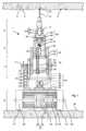
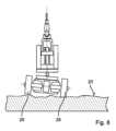
図1及び図2は、シェルにおける設置作業用の自動位置合わせツールガイド1(以下単にツールガイド1と記す)の一例を示す。例えば、通風管の設置にはシェルの天井3に複数の穴2が必要である。穴2は、予め指定された位置4に、例えば位置合わせされて位置付けられるものである。更に、穴2は、例えば垂直に方向付けられた状態で、互いに平行であるものとされている。位置4は、例えば、図面に示されている。監督者が、シェルの天井3上の色目印によって位置4を示すことができる。天井3での他の設置作業は、釘を打つこと、ねじをねじ込むこと、研磨などを含み得る。 1 and 2 show an example of an automatic alignment tool guide 1 (hereinafter simply referred to as tool guide 1) for installation work in a shell. For example, the installation of ventilation pipes requires a plurality of
図1及び図2は、自動位置合わせツールガイド1の一実施例を概略的に示す。ツールガイド1は、可搬式電動ツール6用の保持具5と、電動式昇降機構7と、電動式ピボットジョイント8と、電動式シャーシ9と、コントローラ10と、コンソール11とを有する。 1 and 2 schematically illustrate an embodiment of an automatic
使用者は、用途に応じて、ツールガイド1に、適切な可搬式電動ツール6及び適切なツール12を装備させることができる。シェルに穴2を穿孔するために、これは、例えば、インパクト機構13を有するハンマードリル及び焼結カーバイドチップを有するドリルであり得る。可搬式電動ツール6は、昇降機構7上の保持具5に挿入され得る。ロック14は、保持具5内の可搬式電動ツール6を固定する。ロック14は、ツールなしで解除できることが好ましい。他の実施例では、可搬式電動ツールは、保持具5に恒久的に接続することができ、例えば、ねじ止めすることができる。 The user can equip the
ハンマードリルは、可搬式電動ツール6の単なる一例である。他の例は、電気式スクリュードライバ、釘締め機、アングルグラインダ、グルーガン、スプレーガンなどである。可搬式電動ツール6の一種は、その操作において、交換可能なツール12、例えば、ドリル、たがね、スクリュードライバのビット、切削ホイールなどを駆動する。別の種類の可搬式電動ツール6は、消耗材料、例えば、釘、ねじ、塗料、接着剤を直接処理する。可搬式電動ツール6は、ツール12を駆動するか又は消耗材料を駆動若しくは適用するその駆動部によって区別される。使用者は、可搬式電動ツール6を使用するためにいかなる手動力も印加する必要はない。可搬式電動ツールは、電動ツールと呼ばれる。電源15は、電気的に又は燃料によって駆動され得る。例としては、電気モータ、電気ポンプ、ガス供給内燃機関、粉末駆動式(powder-driven)ピストンなどが挙げられる。電源15は、(始動)ボタン16に結合されている。始動ボタン16が押されると、電源15が起動される。始動ボタン16は、好ましくは、遠隔で始動又はロックされ得る。 A hammer drill is just one example of a
可搬式電動ツール6は、市販の手持型可搬式電動ツール6であり得る。手持型可搬式電動ツール6は、ハンドル17、及び典型的には、追加のハンドルを固定するためのハウジング部18を有する。可搬式電動ツール6は、ハンドルなしで構成され得る。保持具5は、手持型でない可搬式電動ツール用に構成することもできる。 The
手持型電動ツール6は、その構造によって画定される作業軸19を有する。ツール12のチップ又は消耗材料のチップは、作業軸19上にある。チップは、作業軸19に沿って移動する。チップは、被作業下地表面、例えば天井3に最初に接触する。 The hand-held
ツールガイド1の状態図を図4に示す。使用者は、コンソール11を用いてツールガイド1を起動させる。シャーシ9は、使用者がツールガイド1を空間全体にわたって床20の上で移動させることができる(駆動)モードS1にある。コントローラ10は、ツールガイド1の操縦システム21を起動させる。使用者は、コンソール11を介して、移動方向及び速度を予め指定することができる。使用者は、ツールガイド1を、印を付けた位置4のうちの1つに案内する。シャーシ9は、シャーシ9を床20の上で自力で移動させる駆動部22を有する。シャーシ9の移動の方向及び速度は、ツールガイド1の操縦システム21によって制御される。この目的のために、操縦システム21は、とりわけ、コンソール11を介して入力された、移動の速度及び方向に関する予め指定された事項(prespecification)を処理する。 A state diagram of the
使用者は、印を付けた位置4にツールガイド1を維持する。使用者は、コンソール11を介して、シャーシ9を(起立)モードS2に切り替える。コントローラ10は、操縦システム21を使用者に対してブロックするか又は操縦システム21を停止させるように操縦システム21を切り替える。操縦システム21は、コンソール11を介して入力された移動の速度及び方向に関する予め指定された事項を無視する。ツールガイド1は、現在とっている位置4に留まる。操縦システム21は、現在位置4を検出することができる。シャーシ9が現在位置4を離れた場合又は前記位置から移動した場合、操縦システム21は、シャーシ9を検出位置4に戻すために、制御信号を自動的に生成する。 The user maintains the
使用者は、昇降機構7を用いて可搬式電動ツール6を上昇させるために、コンソール11を介して、(昇降)モードS3を起動させることができる。コントローラ10は、昇降モードが起動され得る前に、シャーシ9を強制的に起立モードS2にする。コントローラ10は、シャーシ9が起立するまで、昇降モードの起動を遅延させることができる。昇降モードでは、使用者用の制御ステーション23が有効化又は起動される。使用者は、コンソール11を介して、昇降機構7の移動方向24、即ち上又は下、昇降速度及び位置を予め指定することができる。これに対応して、保持具5は、昇降機構7によって移動される。制御ステーション23は、コンソール11を介して予め指定された垂直移動方向及び昇降速度を考慮に入れて、昇降機構7の推進システム25を制御する。昇降機構7は、保持具5、及び可能であれば、保持具5に挿入された可搬式電動ツール6を、固定された昇降軸26に沿って上昇又は下降させる。昇降機構7は、昇降軸26上での単軸の並進運動に限定される。 The user can activate (lift) mode S3 via the
可搬式電動ツール6の作業軸19は、昇降軸26に平行である。一改良形態では、保持具5の構造によって、平行な位置合わせを強制する。例えば、保持具5の形状が可搬式電動ツール6のハウジングに対応することにより、可搬式電動ツール6は、既定の1つの方向でのみ保持具5に挿入することができる。一改良形態では、作業軸19を昇降軸26上に位置合わせするために、保持具5は、昇降軸26に対して傾斜した(枢)軸を中心に枢動することができる。 The working
天井3に対する昇降軸26、したがって、作業軸19の位置合わせは、シャーシ9によって動的に実施される。シャーシ9は、少なくとも、シャーシ9が水平床20上に立っていることを条件として、昇降軸26を垂直に、即ち重力に平行に位置合わせする。 The alignment of the lifting
可搬式電動ツール6は、好ましくは、制御ステーション23を介してスイッチを入れることができる。ツール12は、天井3で作業することができ、例えば、穴2を穿孔することができる。コントローラ10は、天井3での作業中に昇降機構7の推進システム25を自動的に制御する(作業)モードS4を有することができる。作業モードは、例えばコンソール11において手動で起動させることができる。作業モードにおいて、制御ステーション23は、昇降機構7の昇降速度を、ツール12の作業の進み具合に対応させる。昇降機構7及びツール12は、過剰な負荷から保護され得る。作業目標、例えばドリル穴の深さは、制御ステーション23に予め指定され得る。作業目標に到達した後、制御ステーション23は推進システム25を自動的に停止させることができる。更に、制御ステーション23は、ツール12が天井3から離れる程度まで、昇降機構7を自動的に下降させることができる。 The
ここで、使用者は、ツールガイド1を次の印を付けた位置4に方向転換することができる。使用者は、ツールガイド1を駆動モードS1に切り替える。制御ステーション23は、使用者に対してブロックされる。可搬式電動ツール6は、強制的にオフに切り替えられる。ツールガイド1は、起動前に、ツール12が天井3と依然として係合しているかどうかを確認することができる。例えば、操縦システム21は、シャーシ9を予め指定されたわずかな距離だけ一方向27に移動させ、相殺するトルクがシャーシ9に作用しているかどうかを確認する。操縦システム21は、シャーシ9を以前の位置4に戻し、起立モードに切り替え、制御ステーション23に昇降機構7を下降させるように促す。 The user can now turn the
シャーシ9は、駆動部22に結合された2つの車輪28を有する。2つの車輪28は、横軸又は車輪軸29上で互いに対してオフセットして配置されている。車輪軸29は、2つの車輪28の中心を通って延びている。車輪28は、互いに対して平行な場合がある、又は車輪28は、車輪のキャンバー角及び/若しくはトー角が理由で、互いに対して数度だけ傾斜している。2つの車輪28は、実質的に車輪軸29を中心に回転する。各車輪28は、駆動部22に結合されている。駆動部22は、例えば2つの電気モータ30を含み得る。車輪28はそれぞれ、1つの電気モータ30の回転子31に直接配置されている。代替として、車輪28は、クラッチ及びトランスミッションを介して中央電気モータ30に結合され得る。駆動部22は、車輪軸29を中心に作用するトルクを車輪28にかける。回転駆動された車輪28は、シャーシ9を床20上で移動させる。2つの車輪28が同一速度で回転するとき、シャーシ9は直進する。車輪28は、駆動部22によって個別に駆動され得る。車輪28の異なるトルク及び異なる回転速度により、シャーシが角を回って移動することを可能にする。シャーシ9をその垂直軸を中心に回転させるために、車輪28は、反対方向に駆動され得ることが好ましい。駆動部22は、2つの車輪28の回転速度及びトルクの制御信号を操縦システム21から受信する。操縦システム21は、予め指定された操縦動作、例えば、使用者によって予め指定された操縦動作に応答して、制御信号を生成する。駆動部22は、車輪28の出力トルク及び回転速度を検出するためのセンサシステムを有することができる。検出された測定データは、操縦動作の偏差を補正するために、操縦システム21に伝送され得る。 The
このシャーシ9及びツールガイド1は、2つの車輪28のみによって床20の上に立っている。2つの接触点P1、P2は、車輪軸29に平行な線上にある。線の外に、静的に安定した起立姿勢のための、床20との第3の接触点はない。ツールガイド1は、対策なしでは転倒する。操縦システム21は、昇降機構7の重心Gの釣合いを恒久的にとることによって動的平衡を実現する。操縦システム21は、重心Gの検出に基づいて、駆動部22を作動させ、転倒を防ぐトルクを生成する。 This
昇降機構7は、ピボットジョイント8によってシャーシ9上に取り付けられている。昇降機構7は、ピボットジョイント8によって予め指定された1つの枢軸32のみを中心にシャーシ9に対して傾斜させることができる。枢軸32は、車輪軸29に垂直に方向付けられていることが好ましい。昇降機構7は、車輪軸29に垂直な平面に関して、シャーシ9、特に駆動部22及び車輪軸29に対して動かない状態で配置されている。昇降機構7は、駆動部22の固定子33に強固に接続されていることが好ましい。駆動部22は、同じ大きさ及び反対の回転方向のトルクと反作用トルクを原則的に対で生成する。トルクは、駆動部22の回転子31を介して車輪28に作用する。反作用トルクは、駆動部22の固定子33を介して昇降機構7に作用する。 The
ツールガイド1の重量は、シャーシ9の重量及び昇降機構7の重量で構成される。可搬式電動ツール6の重量は、昇降機構7の重量に単に加えられる。シャーシ9の重心は、ほぼ車輪軸29上に位置する。駆動部22の車輪28及び電池34は、車輪軸29を中心に対称に配置されている。昇降機構7の重心Gは、車輪軸29より上に位置する。ツールガイド1は、重心Gが車輪軸29の垂直方向上方にある場合、準安定的でしかなくても起立はする(平衡状態、図5)。横方向の偏位xはゼロに等しい。重心Gが車輪軸29に対して横方向35にオフセットしている場合、即ち、横方向の偏位xがゼロに等しくない場合(図6)、ツールガイド1は転倒する。 The weight of the
操縦システム21は、昇降機構7の重心Gの横方向の偏位xを検出するための(重心)センサ36を有する。重心Gの横方向の偏位xが平衡の範囲外にあると、測定可能な変数が異なる結果となる。昇降機構7は、重力に対して傾斜しており、これに対応して、重心センサ36は、傾斜センサを含み得る。転倒運動は、特徴的な加速につながり、重心センサ36は、速度、加速度、回転率及び/又は車輪軸29を中心とした回転運動を決定するためのジャイロセンサ、加速度センサ、回転率センサなどを含み得る。傾斜した昇降機構7は、駆動部22にトルクを作用する。重心センサ36は、トルク、非垂直力などを検出するためのトルクセンサ、力センサなどを含み得る。センサは、機械的、光学的、磁気的又は電気的効果に基づいて、上述の変数を検出することができる。 The
操縦システム21は、昇降機構7を直立させるためのトルクを偏位xに基づいて決定する制御シーケンスを含む。例えば、操縦システム21は、偏位xに比例するトルクを予め指定することができる。操縦システム21は、トルクを生成する駆動部22に、制御信号の形態でトルクを伝送する。制御シーケンスは、偏位xをゼロに補正する制御ループを含み得る。例えば、制御シーケンスを可搬式電動ツール6の異なる重量に合わせて調整するために、ブースト因子及び積分成分などの制御パラメータを調整できることが好ましい。 The
昇降機構7は、駆動部22のモータ力により、垂直に位置合わせされる。昇降機構7は、平衡状態を崩すことにより始動させることができ、制御シーケンスを受けて垂直位置合わせ状態の周りで繰り返し揺れ動くことができる。揺動運動後、使用者は、それ以上のあらゆる運動を確認することはできない。昇降機構7に作用するトルクは、車輪28に作用するトルクと対抗する。これに対応するように車輪28は回転し、その結果、シャーシ9は偏位xの方向27に移動する(図6)。シャーシ9は、昇降機構7と同様に、中心位置の周りで揺れ動く。床20上での車輪28の摩擦及びグリップにより、揺れ動きを減衰させる。 The
シャーシ9の静的に不安定な起立姿勢及び釣合いを使用して、昇降軸26を垂直に位置合わせする。動的平衡状態において、重心Gは、車輪軸29の垂直上方に位置する。昇降機構7は、重心G及び車輪軸29を通る線が昇降軸26に平行であるように、車輪軸29に対して配置されている。重心Gの位置4を様々な可搬式電動ツール6に対して調整するために、一例として示す昇降機構7は、保持具5上に補償用重り37を有する。補償用重り37は、昇降軸26から異なる距離でロックされ得る。補償用重り37の代わりに、調節により、偏位xを予め指定されたオフセットに補正することができる。オフセットには、昇降機構7の作動位置を考慮に入れることが好ましい。動釣合いにより、昇降機構7の高さに関係なく昇降軸26を垂直に位置合わせする。 The statically unstable upright position and counterbalance of the
動釣合いにより、車輪軸29が水平にある場合の垂直位置合わせを確実にする。偏位xは、車輪軸29に垂直な平面内に位置する。平坦でない床20又は傾斜した床20の場合、車輪軸29は、水平面に対して傾斜し得る(図7)。車輪軸29の傾斜38は、昇降機構7の同等の傾斜に変換される。傾斜38は、ツールガイド1の前頭面内に位置する。前頭面は、車輪軸29及び昇降軸26に及ぶ。車輪軸29の傾斜38は、動釣合いによって直接補償できない。 The dynamic balance ensures vertical alignment when the
天井3での作業のために、傾斜38も補償されることが好ましい。昇降モードS3が起動されると、一例として示すコントローラ10は、傾斜38の発生に備える。ツールガイド1が予め指定された位置4に配置されると、使用者又は外部コントローラ10は昇降モードS3を起動させる。補償は、異なるモードでも発生させることができる。例えば、特定のモードを補償用に提供することができ、このモードは、例えば、位置4に到達した時又は使用者の要求により自動的に始動される。 Preferably, for working on the
ツールガイド1は、昇降機構7をシャーシ9に対して故意に枢動させることにより傾斜38を補償することができる。昇降機構7は、ピボットジョイント8によってシャーシ9に締結されている。ピボットジョイント8により、前頭面の昇降機構7が枢動することを可能にする。傾斜コントローラ39及び(枢動)駆動部40が、昇降機構7をピボットジョイント8を中心に枢動させることによって、昇降機構7を重力の方向と平行に位置合わせする。 The
ピボットジョイント8は、1つの枢軸32を有し、この1つの枢軸32を中心に、昇降機構7をシャーシ9に対して枢動させることができる。枢軸32は、好ましくは、前頭面に垂直であるか又は前頭面に対して少なくとも45度の角度である。車輪軸29に対する枢軸32の向きにより、車輪軸29に垂直な、シャーシ9の動釣合いのための運動と、昇降機構7を車輪軸29に沿って位置合わせするための運動を分離する。 The pivot joint 8 has one
枢動駆動部40は、ピボットジョイント8の近傍に配置されていることが好ましい。一例として示す枢動駆動部40は、電気モータ41及びベルト駆動部42を含む。電気モータ41は、シャーシ9上に取り付けられている固定子43と、昇降機構7に結合されている回転子44とを有する。同様に、別の実施例では、固定子は、昇降機構7に取り付けることができ、回転子は、シャーシ9に結合することができる。回転子31の結合は、ベルト駆動部42によって解除される。ベルト駆動部42は、ピボットジョイント8に懸架された昇降機構7に回転子44のトルクを伝達し、また、昇降機構7によって作用されるトルクを回転子44に伝達する。歯車を備えたトランスミッションの場合とは対照的に、ベルト駆動部42は、トルクを伝達するための運動を行う必要はない。更に、昇降機構7から発生したトルクと電気モータ41から発生したトルクとの間に時間のずれは生じない。これにより、傾斜38のより堅牢且つより急速な補正を可能にする。更なる重要な点は、昇降機構7によって作用されるトルクは、回転子44に戻る(retrospective)効果を有することである。歯車を備えたトランスミッション、例えば、遊星歯車トランスミッションは、駆動スピンドルから出力スピンドルにのみトルクを伝達することができ、出力スピンドルから駆動スピンドルへの反対方向の移動は阻止し得る。歯車を備えた単純なトランスミッションは、その遊びが理由で、ピボットジョイントの補正には好適でない。 Preferably, the pivot drive 40 is arranged in the vicinity of the pivot joint 8. The pivot drive 40 shown by way of example includes an
一例として示すベルト駆動部42は、駆動ローラ45及びベルト46を有する。駆動ローラ45は、回転子44に強固に接続されている。例えば、駆動ローラ45は、回転子44のシャフト47に取り付けられ得る。ベルト46は、駆動ローラ45上に案内される。駆動ローラ45のトルクは、ベルト46に導入される。ベルト46は、昇降機構7に締結されている。枢軸32を中心とした回転方向のトルクと枢軸32を中心とした反対の回転方向のトルクとを伝達できるようにするために、一例として示すベルト46は、2つの箇所48に締結されている。2つの箇所は、一致させることもでき、この場合、ベルトは、2つの反対方向から機能する。追加の補助ローラ49は、ベルトを案内し、ベルトに張力をかけることができる。 The
傾斜コントローラ39は、傾斜センサ50を含む。傾斜センサ50は、前頭面内における、重力51の方向に対する昇降機構7の傾斜38を決定することができる。傾斜センサ50は、例えば、重心センサ36によって又は同様の手法で実装され得る。傾斜センサ50は、重力に対する昇降機構7の傾斜38を直接決定することができる、又は水平面に対する車輪軸29の傾斜によって傾斜38を間接的に決定することができる。傾斜コントローラ39は、傾斜38が最小限になるように枢動駆動部40を補正する。
操縦システム21は、例えば、移動方向及び速度の入力要素を有するコンソール11を含む。一例として示すコンソール11は、二軸ジョイスティックに基づく。他のコンソールは、例えば、移動方向用のステアリングホイール及び速度用のスライドを有し得る。コンソール11は、ツールガイド1から取り外しできることが好ましい。コンソール11によって生成された制御信号は、無線に基づく手法で、光学的に、又は有線に基づく手法で駆動部22に伝送される。操縦システム21は、使用者によってシャーシ9に作用された押す力又は引く力を検出することができる。力の作用下で、シャーシ9は、押す力又は引く力の方向27に傾く。操縦システム21は、シャーシ9の偏位xを検出する。シャーシ9の速度は、例えば、偏位xに比例させることができる。 The
一例として示す昇降機構7は、線形レールガイド52に基づく。2本の平行なプロファイルレール53が、シャーシ9に締結されている。2本のプロファイルレール53は、昇降軸26を画定する。回転子54が、2本のプロファイルレール53に係合する。回転子54は、昇降軸26に沿ってプロファイルレール53上を移動することができる。電気モータ55及びスピンドル56は、回転子54用の推進システム25を形成する。スピンドル56は、2本のプロファイルレール53の間に回転自在に取り付けられている。回転子54は、スピンドル56に係合するねじ山57を有する。電気モータ55は、スピンドル56をその長手方向軸を中心に回転させ、ねじ山57は、この回転運動を、昇降軸26に沿った運動に変換する。図示される昇降機構7は、入れ子式の昇降機構の一例である。プロファイルレール及び回転子54の代わりに、又はそれに加えて、一方を他方の中に挿入した管を同様に使用できる。別の推進システム25は、モータによって駆動される歯付きラック及びピニオンに基づく。代替として、液圧プレス又は空気圧プレスも昇降機構7を上昇させることができる。 The
一例として示す昇降機構7は、動力駆動式昇降機構7に加えて、手動入れ子式プラットフォーム58を含み得る。プラットフォーム58は、比較的コンパクトな状態で構築され得る。動力駆動部分を、プラットフォームによって基準高さまで運ぶことができる。プラットフォーム58は、一段式又は多段式プラットフォームであり得る。一例として示すプラットフォーム58は、レールガイドに基づく。 The
一例として示す保持具5は、張力ストラップ60を備えた谷状のトレイ59を有する。ハンドル17をトレイ59内に配置することができ、トレイ59内で張力ストラップ60によって固定することができる。可搬式電動ツール6のハウジングは、第2の張力ストラップ61により保持具5に縛り付けることができる。保持具5は、昇降軸26に垂直に移動できることが好ましい。保持具5は、例えば、あり継ぎガイド62上を移動可能であり得る。使用者は、作業軸19を車輪軸29に対して垂直に位置付けることができる。保持具5は、昇降軸26に平行な、作業軸19の精密な位置合わせを可能にする角度設定部を含み得る。角度設定部は、例えば、継手及び調整ねじを含む。 The
昇降機構7は、天井3への接触圧による力を決定するためのセンサ63を備えていることが好ましい。例えば、保持具5は、ばね64上で垂直方向27に支持されている。接触圧による力により、ばね64を圧縮する。変位センサ65、例えばスライドポテンショメータは、ばね64が圧縮される変位距離を決定する。ばね定数が既知であれば、センサ63は、接触圧による力を決定する。接触圧による力を決定するための他のセンサは、圧電効果、歪みゲージなどに基づき得る。他の改良形態は、接触圧による力を間接的に決定する。例えば、センサ63は、推進システム25の電力消費、例えば電流消費の評価を含む。電力消費と接触圧による力の測定値との相関は、センサ内のテーブルに格納される。天井3に対するツール12の初期接触圧は、センサ63によって、接触圧による力の急増として検出される。センサ63は、ツール12が天井3に当たっていることを制御信号で制御ステーション23に示す。それに応じて、制御ステーション23は、昇降機構7の手動制御を停止し、作業モードに切り替えることができる。好ましい変形形態では、接触圧による力の目標値が制御ステーション23に格納されている。目標値は、使用者によって事前に入力又は選択され得る。目標値は、ツール12、例えば、ドリルの直径に依存する。推進システム25は、接触圧による力が一定になるように補正される。センサ63は、保護回路66の一部として、接触圧による力の測定値を提供することができる。測定値が閾値を超えた場合、保護回路66は昇降機構7の上昇を停止する。 Preferably, the
一改良実施例では、ツールガイド1は、ツール12が天井3に触れた場合、動釣合いを一時停止することができる。接触点が天井3にある状態で、ツールガイド1は、静止して起立することができる。ツールガイド1は、車輪28がブレーキ67によってロックされる停止モードS5に切り替えることができる(図9)。釣合い及び関連するわずかな揺れ動き運動は止まる。 In one improved embodiment, the
ツールガイド1は、天井3との接触を検出する(接触)センサ68を有する。典型的には、ツール12、消耗材料又は可搬式電動ツール6は、天井3に触れる。保持具5は、天井3に間接的に触れる。接触センサ68は、(接触)信号をコントローラ10に出力し、接触信号は、ツール12が天井3と接触しているかどうかに関する符号化された情報を含む。接触センサ68は、例えば、昇降機構7の接触圧による力又は接触圧による力の測定値を評価することができる。接触センサ68は、接触圧による力が閾値を超える場合に又は接触圧による力の変化率が閾値を超える場合に、接触を示す。2つの車輪28及び天井3の接触点を介してツールガイド1を静的に安定な起立姿勢に保持するのに、関連する接触圧による力が十分であるような大きさに閾値が設定されることが好ましい。接触センサ68は、例えば、センサ63又は類似のセンサ63によって実現され得る。 The
接触信号が印加された場合、コントローラ10は、シャーシ9の釣合いをとることを一時停止することが好ましい。コントローラ10は、接触信号が最小限の時間にわたって印加されるまで、一時停止を遅延させることができる。接触信号が印加された場合、操縦システム21は、昇降機構7が垂直に位置合わせされているかどうかを確認する。操縦システム21が垂直位置合わせ状態からの偏差を検出した場合、それに応答して、制御ステーション23は昇降機構7を下降させる。下降は、所定の行程、例えば1cmで行われ得る。代替として、行程は、垂直位置合わせ状態からの偏差及び/又は昇降機構7の高さに基づいて決定され得る。例えば、行程は、角度寸法の偏差と昇降機構7の現在高さとの積に比例する。ツール12は、天井3から離される。その結果、接触センサ68は、天井3との接触をもはや示さない。コントローラ10は即座に、操縦システム21を用いて釣合いを再アクティブ化する。操縦システム21は、昇降機構7を垂直に位置合わせする。コントローラ10は、昇降機構7が垂直に位置合わせされるまで、本段落に記載されている方法を反復的に繰り返すことができる。その後、コントローラ10は、少なくとも好ましくは接触信号が印加されるまで、昇降機構7を上昇させる。その後、ツールガイド1は、垂直に位置合わせされる。 Preferably,
シャーシ9は、好ましくはブレーキ67を有する。ブレーキ67は、好ましくは、ツールガイド1が垂直に位置合わせされ、接触信号が印加されるとすぐに起動される。ブレーキ67は、シャーシ9の車輪28を永続的にロックするパーキングブレーキである。ブレーキ67は、例えば、モータブレーキとして実現される。ブレーキ67は、車輪28の運動に対抗する電磁力を発生させる。ブレーキ67は、受動的であり得る。電気モータ30は、前記電気モータの回転子31が回転した場合、発電機の原理に従い、固定子33内で電流を発生させることができる。発電機の原理を用いた電気モータ30の例は、直流モータ、交直両用電気モータなどである。発電機によって発生した電流は、負荷抵抗器を介してブレーキ67により短絡させる。反作用磁場は、回転子31の回転運動に対抗する。代替として、回転速度センサ又は運動センサが運動を検出することができる。この運動を打ち消すように推進システム25を操縦するために、操縦システム21は、対応する制御信号を確認する。ブレーキ67はまた、シャーシ9内の機械式ブレーキ、例えば、ディスクブレーキ又はドラムブレーキによって実現され得る。機械式ブレーキ67は、モータブレーキを支援することができる。
ツールガイド1は、1つ以上の電池34、69を有する。電池69は、操縦システム21、制御ステーション23、駆動部22の電気モータ30、推進システムの電気モータ55、及び可能であれば、可搬式電動ツール6に電力を供給する。電池69は、据置電池34及び1つ以上の取り外し可能な電池69を含み得る。据置電池34は、好ましくはシャーシ9内に組み込まれている。ツールガイド1は、取り外し可能な電池69用の対応する電気機械インターフェースを有する。インターフェースは、例えば、可搬式電動ツール6のインターフェースに対応する。使用者は、放電した電池69を充電済み電池69と交換することができ、放電した電池69を別個の充電ステーションで充電することができる。可搬式電動ツール6の消費電力は、典型的には、200ワットを大幅に超える。それに応じた大きな静電容量が電池によって提供される必要がある。据置電池34は、他の電池69に電気的に接続されている。充電調整器70が、据置電池34を他の電池69で充電する。充電調整器70は、好ましくは、据置電池34の充電状態を、非常時の値を上回るように維持する。使用者は、他の電池69をリスクなく取り外すことができる。非常時の値が理由で、据置電池34は、少なくとも10分間、好ましくは少なくとも30分間にわたって、シャーシ9の釣合いをとるのに十分な充電状態を有する。 The
ツールガイド1は、電池34、69の充電状態が非常時の値を下回った場合、(非常)モードS9に入る。非常モードは、ツールガイド1の安全な起立姿勢を確保する。シャーシ9及び操縦システム21に、電力が供給される。使用者は、ツールガイド1を充電ステーション又は別の所望の場所に移動させることができる。他の消費部は、好ましくは、作動停止され、特に、昇降機構7及び可搬式電動ツール6は、作動停止される。例えば、制御ステーション23は、使用者による入力をブロックすることができる。使用者は、制御ステーション23をもはや上昇させることはできない。可搬式電動ツール6は、スイッチによって電池から切り離され得る。非常モードにおいて、昇降機構7は、最低高さに自動的に引き込まれ得る。非常モードでは、ツールガイド1は、非常モードを光学的に又は音響的に示すことができる。 The
Claims (9)
Translated fromJapanese可搬式電動ツール(6)を固定するための保持具(5)と、
前記保持具(5)が取り付けられ、前記保持具(5)を昇降軸(26)に平行に上昇させるための推進システム(25)を有する、昇降機構(7)と、
自動釣合いシャーシ(9)であって、車輪軸(29)上の2つの車輪(28)と、前記車輪(28)に結合された駆動部(22)と、操縦システム(21)とを有する、自動釣合いシャーシ(9)と、
前記車輪軸(29)に垂直かつ重力に平行な平面に対する、前記昇降機構(7)の重心(G)の偏位(x)を検出するための重心センサ(36)と
を備え、
前記操縦システム(21)は、前記駆動部(22)を作動させて、前記偏位(x)を相殺するトルクを出力させるように構成され、
前記車輪軸(29)に平行且つ前記昇降軸(26)に平行な前頭面内における、重力に対する前記昇降機構(7)の傾斜(38)を検出するための傾斜センサ(50)と、
前記昇降機構(7)を前記シャーシ(9)に取り付けるためのピボットジョイント(8)であって、前記ピボットジョイント(8)の枢軸(32)は、前記前頭面に対して傾斜しているか又は前記前頭面に垂直である、ピボットジョイント(8)と、
前記ピボットジョイント(8)に結合されており、前記前頭面内における、前記重力に対する前記昇降軸(26)の傾斜(38)を調整するための枢動駆動部(40)と、
前記枢動駆動部(40)を作動させて、前記傾斜(38)を最小限にするように構成されている傾斜コントローラ(39)と、
を含み、
前記昇降機構(7)は前記可搬式電動ツール(6)の前記天井(3)への接触圧による力を決定するためのセンサ(63)を備え、測定値が閾値を超えた場合前記昇降機構(7)の上昇を停止し、
前記自動位置合わせツールガイド(1)は前記天井(3)との接触を検出する(接触)センサ(68)を有し、接触信号が検出された場合、前記操縦システム(21)は、昇降機構(7)が垂直に位置合わせされているかどうかを確認し、垂直位置からの偏差を検出した場合には前記昇降機構(7)を下降させ、前記可搬式電動ツール(6)は前記天井(3)から離れ、前記操縦システム(21)は昇降機構(7)が垂直になるまで位置合わせを繰り返す、
自動位置合わせツールガイド。An automatic alignment tool guide (1) for alignment of a working axis (19) of a portable electric tool (6) working against a ceiling (3), comprising:
a holder (5) for fixing the portable electric tool (6);
a lifting mechanism (7) to which the holding device (5) is attached and having a propulsion system (25) for raising the holding device (5) parallel to the lifting axis (26);
a self-balancing chassis (9) comprising two wheels (28) on a wheel axle (29), a drive (22) connected to said wheels (28) and a steering system (21); an automatic balancing chassis (9);
a center of gravity sensor (36) for detecting a deviation (x) of the center of gravity (G) of the lifting mechanism (7) with respect to a plane perpendicular to the wheel axis (29) and parallel to gravity;
The steering system (21) is configured to actuate the drive unit (22) to output a torque that offsets the deviation (x),
an inclination sensor (50) for detecting the inclination (38) of the elevating mechanism (7) with respect to gravity in a coronal plane parallel to the wheel axis (29) and parallel to the elevating axis (26);
a pivot joint (8) for attaching the lifting mechanism (7) to the chassis (9), the pivot (32) of the pivot joint (8) being inclined with respect to the coronal plane or a pivot joint (8) perpendicular to the coronal plane;
a pivoting drive (40) coupled to the pivot joint (8) for adjusting the inclination (38) of the lifting axis (26) relative to gravity in the coronal plane;
a tilt controller (39) configured to operate said pivot drive (40) to minimize said tilt (38);
including ;
The lifting mechanism (7) includes a sensor (63) for determining the force due to the contact pressure of the portable electric tool (6) on the ceiling (3), and if the measured value exceeds a threshold, the lifting mechanism (7) Stop the rise,
The automatic alignment tool guide (1) has a (contact) sensor (68) for detecting contact with the ceiling (3), and if a contact signal is detected, the steering system (21) (7) is vertically aligned, and if a deviation from the vertical position is detected, the lifting mechanism (7) is lowered, and the portable electric tool (6) is moved to the ceiling (3). ), the steering system (21) repeats the alignment until the lifting mechanism (7) is vertical;
Automatic alignment tool guide.
前記自動位置合わせツールガイド(1)の前記車輪軸(29)に垂直かつ重力に平行な平面に対する前記昇降機構(7)の前記重心(G)の偏位(x)を検出する工程と、
前記駆動部(22)が前記偏位(x)を相殺するトルクを出力するように、前記駆動部(22)を作動させる工程と、
を特徴とする制御方法。A method for controlling an automatic alignment tool guide according to any one of claims 1 to 8, comprising:
detecting the deviation (x) of the center of gravity (G) of the lifting mechanism (7) with respect to a plane perpendicular to the wheel axis (29) of the automatic alignment tool guide (1) and parallel to gravity;
activating the drive unit (22) such that the drive unit (22) outputs a torque that offsets the deviation (x);
A control method characterized by:
Applications Claiming Priority (3)
| Application Number | Priority Date | Filing Date | Title |
|---|---|---|---|
| EP19166942.3AEP3718812A1 (en) | 2019-04-03 | 2019-04-03 | Self-aligning tool guide |
| EP19166942.3 | 2019-04-03 | ||
| PCT/EP2020/057936WO2020200868A1 (en) | 2019-04-03 | 2020-03-23 | Self-aligning tool guide |
Publications (2)
| Publication Number | Publication Date |
|---|---|
| JP2022527165A JP2022527165A (en) | 2022-05-31 |
| JP7407835B2true JP7407835B2 (en) | 2024-01-04 |
Family
ID=66092005
Family Applications (1)
| Application Number | Title | Priority Date | Filing Date |
|---|---|---|---|
| JP2021557485AActiveJP7407835B2 (en) | 2019-04-03 | 2020-03-23 | Auto alignment tool guide |
Country Status (5)
| Country | Link |
|---|---|
| US (1) | US20220184790A1 (en) |
| EP (2) | EP3718812A1 (en) |
| JP (1) | JP7407835B2 (en) |
| CN (1) | CN113423600A (en) |
| WO (1) | WO2020200868A1 (en) |
Families Citing this family (6)
| Publication number | Priority date | Publication date | Assignee | Title |
|---|---|---|---|---|
| EP3488978A1 (en)* | 2017-11-23 | 2019-05-29 | HILTI Aktiengesellschaft | Self-aligning tool guide |
| EP3488977A1 (en) | 2017-11-23 | 2019-05-29 | HILTI Aktiengesellschaft | Self-aligning tool guide |
| EP3488974A1 (en) | 2017-11-23 | 2019-05-29 | HILTI Aktiengesellschaft | Self-aligning tool guide |
| CN113829516B (en)* | 2021-08-24 | 2023-12-22 | 中工武大设计集团有限公司 | Collect drilling, install in dress pole device of an organic whole |
| CN114012672B (en)* | 2021-11-09 | 2023-03-14 | 正阳科技股份有限公司 | Hand-held electric tool |
| CN117661866B (en)* | 2023-12-22 | 2024-08-06 | 中铁二十五局集团第三工程有限公司 | Beam body traversing device and beam body traversing method |
Citations (1)
| Publication number | Priority date | Publication date | Assignee | Title |
|---|---|---|---|---|
| US20040007425A1 (en) | 1994-05-27 | 2004-01-15 | Kamen Dean L. | Self-balancing ladder and camera dolly |
Family Cites Families (17)
| Publication number | Priority date | Publication date | Assignee | Title |
|---|---|---|---|---|
| DE3328582A1 (en) | 1982-09-27 | 1984-03-29 | Siemens AG, 1000 Berlin und 8000 München | Mobile ceiling-drilling and assembly appliance for impact plugs |
| JPH06182677A (en)* | 1992-12-21 | 1994-07-05 | Supiide Fastener Kk | Ceiling driller |
| JPH0819765B2 (en)* | 1993-04-19 | 1996-02-28 | 第一工業株式会社 | Automatic ceiling opening machine |
| US5350033A (en)* | 1993-04-26 | 1994-09-27 | Kraft Brett W | Robotic inspection vehicle |
| US5794721A (en)* | 1996-09-06 | 1998-08-18 | Long-Airdox Company | Drilling apparatus |
| JP2011523903A (en)* | 2008-05-21 | 2011-08-25 | ジョージア テック リサーチ コーポレイション | Force balance mobile robot system |
| US8442661B1 (en)* | 2008-11-25 | 2013-05-14 | Anybots 2.0, Inc. | Remotely controlled self-balancing robot including a stabilized laser pointer |
| US8342493B2 (en)* | 2009-11-11 | 2013-01-01 | Koike Aronson, Inc. | Anti-drift turning roll system |
| US8671805B2 (en)* | 2011-05-03 | 2014-03-18 | Illinois Tool Works, Inc. | Ceiling support installation system |
| SE536029C2 (en)* | 2011-11-04 | 2013-04-09 | Atlas Copco Ind Tech Ab | Motor-driven tool and method for operating an automated drilling operation |
| US20170080558A1 (en)* | 2013-03-13 | 2017-03-23 | Double Robotics, Inc. | Telepresence robot with stabilization mechanism |
| WO2016025617A1 (en)* | 2014-08-13 | 2016-02-18 | Sphero, Inc. | Self-propelled device with magnetic coupling |
| US10189528B2 (en)* | 2014-09-15 | 2019-01-29 | Changzhou Airwheel | Self-balancing double-wheeled electrical scooter |
| GB201419182D0 (en)* | 2014-10-28 | 2014-12-10 | Nlink As | Mobile robotic drilling apparatus and method for drilling ceillings and walls |
| CN105537651A (en)* | 2016-03-08 | 2016-05-04 | 长沙市富湘建筑工程有限公司 | Lever hinge type drilling ladder and hole-forming construction method |
| GB2560328B (en)* | 2017-03-07 | 2021-12-15 | Niftylift Ltd | Base unit for a vehicle |
| CN108656032A (en)* | 2018-05-17 | 2018-10-16 | 栾仁卫 | A kind of electronic fast lifting holder of electric hammer and its electric hammer component |
- 2019
- 2019-04-03EPEP19166942.3Apatent/EP3718812A1/ennot_activeWithdrawn
- 2020
- 2020-03-23USUS17/432,267patent/US20220184790A1/ennot_activeAbandoned
- 2020-03-23CNCN202080014671.7Apatent/CN113423600A/enactivePending
- 2020-03-23EPEP20712571.7Apatent/EP3947019B1/enactiveActive
- 2020-03-23WOPCT/EP2020/057936patent/WO2020200868A1/ennot_activeCeased
- 2020-03-23JPJP2021557485Apatent/JP7407835B2/enactiveActive
Patent Citations (1)
| Publication number | Priority date | Publication date | Assignee | Title |
|---|---|---|---|---|
| US20040007425A1 (en) | 1994-05-27 | 2004-01-15 | Kamen Dean L. | Self-balancing ladder and camera dolly |
Also Published As
| Publication number | Publication date |
|---|---|
| EP3718812A1 (en) | 2020-10-07 |
| WO2020200868A1 (en) | 2020-10-08 |
| US20220184790A1 (en) | 2022-06-16 |
| JP2022527165A (en) | 2022-05-31 |
| EP3947019B1 (en) | 2023-11-29 |
| CN113423600A (en) | 2021-09-21 |
| EP3947019A1 (en) | 2022-02-09 |
Similar Documents
| Publication | Publication Date | Title |
|---|---|---|
| JP7407835B2 (en) | Auto alignment tool guide | |
| JP7034283B2 (en) | Self-aligning tool guide | |
| JP7341137B2 (en) | Self-adjusting tool guide | |
| US11478918B2 (en) | Self-aligning tool guide | |
| US20220379457A1 (en) | Improved Self-Balancing Tool Guide | |
| US8464820B2 (en) | Air cushion platform for carrying a manipulator arm and movable robot | |
| US9022135B2 (en) | Torque-applying tool and torque controller therefor | |
| WO2019101482A1 (en) | Self-aligning tool guide | |
| EP3713715B1 (en) | Self-aligning tool guide | |
| EP4132751B1 (en) | Levelling system | |
| US20240189923A1 (en) | Methods, system and electronic module for counterbalancing a weight force of an object | |
| JP2023127657A (en) | Screw driving device | |
| KR20130112989A (en) | Automatic balancing control apparatus and lifting equipment |
Legal Events
| Date | Code | Title | Description |
|---|---|---|---|
| A621 | Written request for application examination | Free format text:JAPANESE INTERMEDIATE CODE: A621 Effective date:20210927 | |
| A977 | Report on retrieval | Free format text:JAPANESE INTERMEDIATE CODE: A971007 Effective date:20221027 | |
| A131 | Notification of reasons for refusal | Free format text:JAPANESE INTERMEDIATE CODE: A131 Effective date:20221107 | |
| A601 | Written request for extension of time | Free format text:JAPANESE INTERMEDIATE CODE: A601 Effective date:20230206 | |
| A521 | Request for written amendment filed | Free format text:JAPANESE INTERMEDIATE CODE: A523 Effective date:20230225 | |
| A131 | Notification of reasons for refusal | Free format text:JAPANESE INTERMEDIATE CODE: A131 Effective date:20230616 | |
| A601 | Written request for extension of time | Free format text:JAPANESE INTERMEDIATE CODE: A601 Effective date:20230912 | |
| A521 | Request for written amendment filed | Free format text:JAPANESE INTERMEDIATE CODE: A523 Effective date:20231022 | |
| TRDD | Decision of grant or rejection written | ||
| A01 | Written decision to grant a patent or to grant a registration (utility model) | Free format text:JAPANESE INTERMEDIATE CODE: A01 Effective date:20231129 | |
| A61 | First payment of annual fees (during grant procedure) | Free format text:JAPANESE INTERMEDIATE CODE: A61 Effective date:20231219 | |
| R150 | Certificate of patent or registration of utility model | Ref document number:7407835 Country of ref document:JP Free format text:JAPANESE INTERMEDIATE CODE: R150 |