JP7407812B2 - Storage devices, loading devices, feeding systems, kits and related methods - Google Patents
Storage devices, loading devices, feeding systems, kits and related methodsDownload PDFInfo
- Publication number
- JP7407812B2 JP7407812B2JP2021521943AJP2021521943AJP7407812B2JP 7407812 B2JP7407812 B2JP 7407812B2JP 2021521943 AJP2021521943 AJP 2021521943AJP 2021521943 AJP2021521943 AJP 2021521943AJP 7407812 B2JP7407812 B2JP 7407812B2
- Authority
- JP
- Japan
- Prior art keywords
- loading
- puller
- medical device
- implantable medical
- sheath
- Prior art date
- Legal status (The legal status is an assumption and is not a legal conclusion. Google has not performed a legal analysis and makes no representation as to the accuracy of the status listed.)
- Active
Links
Images


Classifications
- A—HUMAN NECESSITIES
- A61—MEDICAL OR VETERINARY SCIENCE; HYGIENE
- A61F—FILTERS IMPLANTABLE INTO BLOOD VESSELS; PROSTHESES; DEVICES PROVIDING PATENCY TO, OR PREVENTING COLLAPSING OF, TUBULAR STRUCTURES OF THE BODY, e.g. STENTS; ORTHOPAEDIC, NURSING OR CONTRACEPTIVE DEVICES; FOMENTATION; TREATMENT OR PROTECTION OF EYES OR EARS; BANDAGES, DRESSINGS OR ABSORBENT PADS; FIRST-AID KITS
- A61F2/00—Filters implantable into blood vessels; Prostheses, i.e. artificial substitutes or replacements for parts of the body; Appliances for connecting them with the body; Devices providing patency to, or preventing collapsing of, tubular structures of the body, e.g. stents
- A61F2/0095—Packages or dispensers for prostheses or other implants
- A—HUMAN NECESSITIES
- A61—MEDICAL OR VETERINARY SCIENCE; HYGIENE
- A61F—FILTERS IMPLANTABLE INTO BLOOD VESSELS; PROSTHESES; DEVICES PROVIDING PATENCY TO, OR PREVENTING COLLAPSING OF, TUBULAR STRUCTURES OF THE BODY, e.g. STENTS; ORTHOPAEDIC, NURSING OR CONTRACEPTIVE DEVICES; FOMENTATION; TREATMENT OR PROTECTION OF EYES OR EARS; BANDAGES, DRESSINGS OR ABSORBENT PADS; FIRST-AID KITS
- A61F2/00—Filters implantable into blood vessels; Prostheses, i.e. artificial substitutes or replacements for parts of the body; Appliances for connecting them with the body; Devices providing patency to, or preventing collapsing of, tubular structures of the body, e.g. stents
- A61F2/02—Prostheses implantable into the body
- A61F2/24—Heart valves ; Vascular valves, e.g. venous valves; Heart implants, e.g. passive devices for improving the function of the native valve or the heart muscle; Transmyocardial revascularisation [TMR] devices; Valves implantable in the body
- A—HUMAN NECESSITIES
- A61—MEDICAL OR VETERINARY SCIENCE; HYGIENE
- A61B—DIAGNOSIS; SURGERY; IDENTIFICATION
- A61B50/00—Containers, covers, furniture or holders specially adapted for surgical or diagnostic appliances or instruments, e.g. sterile covers
- A61B50/30—Containers specially adapted for packaging, protecting, dispensing, collecting or disposing of surgical or diagnostic appliances or instruments
- A—HUMAN NECESSITIES
- A61—MEDICAL OR VETERINARY SCIENCE; HYGIENE
- A61F—FILTERS IMPLANTABLE INTO BLOOD VESSELS; PROSTHESES; DEVICES PROVIDING PATENCY TO, OR PREVENTING COLLAPSING OF, TUBULAR STRUCTURES OF THE BODY, e.g. STENTS; ORTHOPAEDIC, NURSING OR CONTRACEPTIVE DEVICES; FOMENTATION; TREATMENT OR PROTECTION OF EYES OR EARS; BANDAGES, DRESSINGS OR ABSORBENT PADS; FIRST-AID KITS
- A61F2/00—Filters implantable into blood vessels; Prostheses, i.e. artificial substitutes or replacements for parts of the body; Appliances for connecting them with the body; Devices providing patency to, or preventing collapsing of, tubular structures of the body, e.g. stents
- A61F2/02—Prostheses implantable into the body
- A61F2/24—Heart valves ; Vascular valves, e.g. venous valves; Heart implants, e.g. passive devices for improving the function of the native valve or the heart muscle; Transmyocardial revascularisation [TMR] devices; Valves implantable in the body
- A61F2/2427—Devices for manipulating or deploying heart valves during implantation
- A61F2/2436—Deployment by retracting a sheath
- A—HUMAN NECESSITIES
- A61—MEDICAL OR VETERINARY SCIENCE; HYGIENE
- A61F—FILTERS IMPLANTABLE INTO BLOOD VESSELS; PROSTHESES; DEVICES PROVIDING PATENCY TO, OR PREVENTING COLLAPSING OF, TUBULAR STRUCTURES OF THE BODY, e.g. STENTS; ORTHOPAEDIC, NURSING OR CONTRACEPTIVE DEVICES; FOMENTATION; TREATMENT OR PROTECTION OF EYES OR EARS; BANDAGES, DRESSINGS OR ABSORBENT PADS; FIRST-AID KITS
- A61F2/00—Filters implantable into blood vessels; Prostheses, i.e. artificial substitutes or replacements for parts of the body; Appliances for connecting them with the body; Devices providing patency to, or preventing collapsing of, tubular structures of the body, e.g. stents
- A61F2/95—Instruments specially adapted for placement or removal of stents or stent-grafts
- A61F2/9522—Means for mounting a stent or stent-graft onto or into a placement instrument
- A61F2/9525—Means for mounting a stent or stent-graft onto or into a placement instrument using a funnel
- A—HUMAN NECESSITIES
- A61—MEDICAL OR VETERINARY SCIENCE; HYGIENE
- A61F—FILTERS IMPLANTABLE INTO BLOOD VESSELS; PROSTHESES; DEVICES PROVIDING PATENCY TO, OR PREVENTING COLLAPSING OF, TUBULAR STRUCTURES OF THE BODY, e.g. STENTS; ORTHOPAEDIC, NURSING OR CONTRACEPTIVE DEVICES; FOMENTATION; TREATMENT OR PROTECTION OF EYES OR EARS; BANDAGES, DRESSINGS OR ABSORBENT PADS; FIRST-AID KITS
- A61F2/00—Filters implantable into blood vessels; Prostheses, i.e. artificial substitutes or replacements for parts of the body; Appliances for connecting them with the body; Devices providing patency to, or preventing collapsing of, tubular structures of the body, e.g. stents
- A61F2/02—Prostheses implantable into the body
- A61F2/24—Heart valves ; Vascular valves, e.g. venous valves; Heart implants, e.g. passive devices for improving the function of the native valve or the heart muscle; Transmyocardial revascularisation [TMR] devices; Valves implantable in the body
- A61F2/2412—Heart valves ; Vascular valves, e.g. venous valves; Heart implants, e.g. passive devices for improving the function of the native valve or the heart muscle; Transmyocardial revascularisation [TMR] devices; Valves implantable in the body with soft flexible valve members, e.g. tissue valves shaped like natural valves
- A—HUMAN NECESSITIES
- A61—MEDICAL OR VETERINARY SCIENCE; HYGIENE
- A61F—FILTERS IMPLANTABLE INTO BLOOD VESSELS; PROSTHESES; DEVICES PROVIDING PATENCY TO, OR PREVENTING COLLAPSING OF, TUBULAR STRUCTURES OF THE BODY, e.g. STENTS; ORTHOPAEDIC, NURSING OR CONTRACEPTIVE DEVICES; FOMENTATION; TREATMENT OR PROTECTION OF EYES OR EARS; BANDAGES, DRESSINGS OR ABSORBENT PADS; FIRST-AID KITS
- A61F2/00—Filters implantable into blood vessels; Prostheses, i.e. artificial substitutes or replacements for parts of the body; Appliances for connecting them with the body; Devices providing patency to, or preventing collapsing of, tubular structures of the body, e.g. stents
- A61F2/02—Prostheses implantable into the body
- A61F2/30—Joints
- A61F2/46—Special tools for implanting artificial joints
- A—HUMAN NECESSITIES
- A61—MEDICAL OR VETERINARY SCIENCE; HYGIENE
- A61F—FILTERS IMPLANTABLE INTO BLOOD VESSELS; PROSTHESES; DEVICES PROVIDING PATENCY TO, OR PREVENTING COLLAPSING OF, TUBULAR STRUCTURES OF THE BODY, e.g. STENTS; ORTHOPAEDIC, NURSING OR CONTRACEPTIVE DEVICES; FOMENTATION; TREATMENT OR PROTECTION OF EYES OR EARS; BANDAGES, DRESSINGS OR ABSORBENT PADS; FIRST-AID KITS
- A61F2/00—Filters implantable into blood vessels; Prostheses, i.e. artificial substitutes or replacements for parts of the body; Appliances for connecting them with the body; Devices providing patency to, or preventing collapsing of, tubular structures of the body, e.g. stents
- A61F2/95—Instruments specially adapted for placement or removal of stents or stent-grafts
- A61F2/9522—Means for mounting a stent or stent-graft onto or into a placement instrument
- A61F2/9526—Means for mounting a stent or stent-graft onto or into a placement instrument using a mandrel
- A—HUMAN NECESSITIES
- A61—MEDICAL OR VETERINARY SCIENCE; HYGIENE
- A61L—METHODS OR APPARATUS FOR STERILISING MATERIALS OR OBJECTS IN GENERAL; DISINFECTION, STERILISATION OR DEODORISATION OF AIR; CHEMICAL ASPECTS OF BANDAGES, DRESSINGS, ABSORBENT PADS OR SURGICAL ARTICLES; MATERIALS FOR BANDAGES, DRESSINGS, ABSORBENT PADS OR SURGICAL ARTICLES
- A61L2300/00—Biologically active materials used in bandages, wound dressings, absorbent pads or medical devices
- A61L2300/40—Biologically active materials used in bandages, wound dressings, absorbent pads or medical devices characterised by a specific therapeutic activity or mode of action
- A61L2300/404—Biocides, antimicrobial agents, antiseptic agents
Landscapes
- Health & Medical Sciences (AREA)
- Cardiology (AREA)
- Engineering & Computer Science (AREA)
- Biomedical Technology (AREA)
- Life Sciences & Earth Sciences (AREA)
- Veterinary Medicine (AREA)
- Heart & Thoracic Surgery (AREA)
- Animal Behavior & Ethology (AREA)
- General Health & Medical Sciences (AREA)
- Public Health (AREA)
- Vascular Medicine (AREA)
- Transplantation (AREA)
- Oral & Maxillofacial Surgery (AREA)
- Surgery (AREA)
- Nuclear Medicine, Radiotherapy & Molecular Imaging (AREA)
- Medical Informatics (AREA)
- Molecular Biology (AREA)
- Prostheses (AREA)
Description
Translated fromJapanese関連出願の相互参照
本出願は、2018年7月6日付けで出願された米国仮特許出願第62/694,660号明細書の利益を主張するものであり、この関連出願の開示全体は、参照により本明細書に援用される。CROSS-REFERENCE TO RELATED APPLICATIONS This application claims the benefit of U.S. Provisional Patent Application No. 62/694,660, filed July 6, 2018, the entire disclosure of which is incorporated herein by reference. Incorporated herein by reference.
本開示は、概して、医療装置の分野に関する。より詳細には、本開示は、埋植可能な医療装置のためのストレージ装置、ローディング装置、供給システム、補助装置、キット及び関連する方法に関する。 TECHNICAL FIELD This disclosure relates generally to the field of medical devices. More particularly, the present disclosure relates to storage devices, loading devices, delivery systems, auxiliary devices, kits and related methods for implantable medical devices.
様々な障害を治療するためのメカニズムを提供する様々な埋植可能な医療装置が開発されている。例えば、埋植可能な弁の1つの潜在的な臨床用途は、下肢の静脈内の自然弁が機能不全を起こし、その結果、逆流、静脈圧力の上昇及び血流の低下が引き起こされる慢性静脈不全を治療することである。埋植可能な弁の別の臨床用途は、肺動脈弁が機能不全を起こし、且つ肺動脈から心臓の右心室への逆流を許容している状態である肺不全を治療することである。埋植可能な弁は、機械的構造と、移植材料とを含み得る。特定の弁構造において、弁移植材料は、埋植可能な弁が、移植材料の完全性を維持するために湿潤状態において保存されることを必要とし得る。例えば、埋植可能な弁は、グルタルアルデヒドなどの化学溶液中において保存することが可能であり、この場合、溶液は、埋植前に埋植可能な弁からすすぎ落しされることを必要とする。すすぎ落し処理に対するニーズは、生体弁の分野で一般的な慣行である。例えば、心臓弁がグルタルアルデヒド又はホルムアルデヒドなどの溶液中において保存されている際、弁は、ストレージ容器から取り出され、患者のベッドサイドにおいて生理食塩水のボール内ですすぎ落しされ、且つ埋植手順前に供給システム内にローディングされることが一般的な慣行であり、この結果、埋植可能な医療装置の汚染の尤度が増大する。 A variety of implantable medical devices have been developed that provide mechanisms for treating a variety of disorders. For example, one potential clinical use for implantable valves is chronic venous insufficiency, in which the native valves in the veins of the lower extremities malfunction, resulting in regurgitation, increased venous pressure, and reduced blood flow. It is to treat. Another clinical use for implantable valves is to treat pulmonary insufficiency, a condition in which the pulmonary valve malfunctions and allows backflow from the pulmonary artery into the right ventricle of the heart. An implantable valve may include a mechanical structure and an implant material. In certain valve constructions, the valve implant material may require that the implantable valve be stored in a moist state to maintain the integrity of the implant material. For example, implantable valves can be stored in a chemical solution such as glutaraldehyde, in which case the solution requires rinsing from the implantable valve prior to implantation. . The need for a rinse-off process is a common practice in the field of bioprosthetic valves. For example, when a heart valve is stored in a solution such as glutaraldehyde or formaldehyde, the valve is removed from the storage container, rinsed in a saline bowl at the patient's bedside, and removed before the implantation procedure. It is common practice for implantable medical devices to be loaded into delivery systems, thereby increasing the likelihood of contamination of the implantable medical device.
従って、新しい且つ有用なストレージ装置、ローディング装置、供給システム、補助装置、キット及び関連する方法に対する必要性が存在する。 Accordingly, a need exists for new and useful storage devices, loading devices, feeding systems, auxiliary devices, kits, and related methods.
本明細書では、様々なストレージ装置、ローディング装置、供給システム、キット及び方法が記述される。 Various storage devices, loading devices, feeding systems, kits, and methods are described herein.
例示的なストレージ装置は、ストレージ部材と、第1キャップと、第2キャップとを含む。ストレージ部材は、第1端部と、第2端部と、第1開口部、第2開口部、パセッジウェイ、分離壁及び複数の孔を画定する本体とを有する。パセッジウェイは、第1開口部から第2開口部まで延在し、且つ第1部分と、第2部分とを有する。分離壁は、第1端部と第2端部との間の場所においてパセッジウェイ内に延在する。パセッジウェイの第1部分は、ストレージ部材の第1端部から分離壁まで延在し、且つパセッジウェイの第2部分は、ストレージ部材の第2端部から分離壁まで延在する。第2部分は、埋植可能な医療装置を収容するようにサイズ設定及び構成されている。複数の孔のそれぞれの孔は、分離壁を通して延在し、且つパセッジウェイの第1部分とパセッジウェイの第2部分との間のアクセスを提供する。第1キャップは、ストレージ部材の第1端部に解放可能に装着されている。第2キャップは、ストレージ部材の第2端部に解放可能に装着されている。 An exemplary storage device includes a storage member, a first cap, and a second cap. The storage member has a first end, a second end, and a body defining a first opening, a second opening, a passageway, a separation wall, and a plurality of holes. The passageway extends from the first opening to the second opening and has a first portion and a second portion. A separation wall extends into the passageway at a location between the first end and the second end. A first portion of the passageway extends from the first end of the storage member to the separation wall, and a second portion of the passageway extends from the second end of the storage member to the separation wall. The second portion is sized and configured to accommodate an implantable medical device. Each hole of the plurality of holes extends through the separation wall and provides access between the first portion of the passageway and the second portion of the passageway. A first cap is releasably attached to the first end of the storage member. A second cap is releasably attached to the second end of the storage member.
例示的なローディング装置は、ストレージ部材と、第1キャップと、ローディング部材と、第2キャップとを含む。ストレージ部材は、第1端部と、第2端部と、第1開口部、第2開口部、パセッジウェイ、分離壁及び複数の孔を画定する本体とを有する。パセッジウェイは、第1開口部から第2開口部まで延在し、且つ第1部分と、第2部分とを有する。分離壁は、第1端部と第2端部との間の場所においてパセッジウェイ内に延在する。パセッジウェイの第1部分は、ストレージ部材の第1端部から分離壁まで延在し、且つパセッジウェイの第2部分は、ストレージ部材の第2端部から分離壁まで延在する。第2部分は、埋植可能な医療装置を収容するようにサイズ設定及び構成されている。複数の孔のそれぞれの孔は、分離壁を通して延在し、且つパセッジウェイの第1部分とパセッジウェイの第2部分との間のアクセスを提供する。第1キャップは、ストレージ部材の第1端部に解放可能に装着されている。ローディング部材は、ストレージ部材の第2端部に解放可能に装着され、且つ第1端部と、第2端部と、第1開口部、第2開口部及び第1開口部から第2開口部まで延在するパセッジウェイを画定する本体とを有する。ローディング部材のパセッジウェイは、第1部分と、第2部分と、第3部分と、第4部分とを有する。ローディング部材のパセッジウェイの第1部分は、ローディング部材の第1端部からローディング部材のパセッジウェイの第2部分まで延在し、且つ第1内径を有する。ローディング部材のパセッジウェイの第2部分は、ローディング部材のパセッジウェイの第1部分からローディング部材のパセッジウェイの第3部分まで延在し、且つローディング部材のパセッジウェイの第1部分からローディング部材のパセッジウェイの第3部分までテーパー化される第2内径を有する。ローディング部材のパセッジウェイの第3部分は、ローディング部材のパセッジウェイの第2部分からローディング部材の第2端部まで延在し、且つローディング部材のパセッジウェイの第1部分の第1内径より小さい第3内径を有する。ローディング部材のパセッジウェイの第4部分は、第3部分から延在し、且つパセッジウェイの第3部分の第3内径より大きい幅を有する。第2キャップは、ローディング部材の第2端部に解放可能に装着されている。 An exemplary loading device includes a storage member, a first cap, a loading member, and a second cap. The storage member has a first end, a second end, and a body defining a first opening, a second opening, a passageway, a separation wall, and a plurality of holes. The passageway extends from the first opening to the second opening and has a first portion and a second portion. A separation wall extends into the passageway at a location between the first end and the second end. A first portion of the passageway extends from the first end of the storage member to the separation wall, and a second portion of the passageway extends from the second end of the storage member to the separation wall. The second portion is sized and configured to accommodate an implantable medical device. Each hole of the plurality of holes extends through the separation wall and provides access between the first portion of the passageway and the second portion of the passageway. A first cap is releasably attached to the first end of the storage member. A loading member is releasably attached to the second end of the storage member and includes a first end, a second end, a first opening, a second opening, and a portion from the first opening to the second opening. and a body defining a passageway extending to. The loading member passageway has a first portion, a second portion, a third portion, and a fourth portion. A first portion of the loading member passageway extends from the first end of the loading member to a second portion of the loading member passageway and has a first inner diameter. The second portion of the loading member passageway extends from the first portion of the loading member passageway to the third portion of the loading member passageway, and the second portion of the loading member passageway extends from the first portion of the loading member passageway to the third portion of the loading member passageway. a second inner diameter tapered to a second inner diameter; The third portion of the loading member passageway extends from the second portion of the loading member passageway to the second end of the loading member and has a third inner diameter that is less than the first inner diameter of the first portion of the loading member passageway. have A fourth portion of the passageway of the loading member extends from the third portion and has a width greater than a third inner diameter of the third portion of the passageway. A second cap is releasably attached to the second end of the loading member.
例示的な供給システムは、シースと、細長い部材と、先端と、把持部材とを含む。シースは、第1端部と、第2端部と、長さと、管腔を画定する本体とを有する。シースの長さは、第1端部から第2端部まで延在する。管腔は、シースの全長を通して延在する。細長い部材は、長手方向軸と、第1端部と、第2端部と、外側表面を画定する本体と、切欠きとを有する。切欠きは、長手方向軸に向かって且つ長手方向軸に対して0度超である角度において細長い部材の第2端部に向かって外側表面から細長い部材の本体内に延在する。先端は、細長い部材の第2端部上に配設され、且つ第1端部と第2端部とを有する。把持部材は、切欠きと先端の第1端部との間で細長い部材に装着されている。把持部材は、第1端部と、第2端部と、長さと、本体とを有する。把持部材は、シース内に配設されるようにサイズ設定及び構成されている。切欠きは、細長い部材の第1端部と把持部材との間に配設されている。 An exemplary delivery system includes a sheath, an elongate member, a tip, and a gripping member. The sheath has a first end, a second end, a length, and a body defining a lumen. The length of the sheath extends from the first end to the second end. The lumen extends through the entire length of the sheath. The elongated member has a longitudinal axis, a first end, a second end, a body defining an outer surface, and a notch. The notch extends into the body of the elongate member from the outer surface toward the second end of the elongate member toward the longitudinal axis and at an angle greater than 0 degrees relative to the longitudinal axis. The tip is disposed on the second end of the elongate member and has a first end and a second end. A gripping member is attached to the elongate member between the notch and the first end of the tip. The gripping member has a first end, a second end, a length, and a body. The gripping member is sized and configured to be disposed within the sheath. The notch is disposed between the first end of the elongate member and the gripping member.
例示的なキットは、ストレージ装置と、装置ガードと、供給システムと、ローディング部材とを含む。ストレージ装置は、ストレージ部材と、第1キャップと、第2キャップとを含む。別の例示的なキットは、ローディング装置と、装置ガードと、供給システムとを含む。ローディング装置は、ストレージ部材と、第1キャップと、ローディング部材と、第2キャップとを含む。 An exemplary kit includes a storage device, a device guard, a feeding system, and a loading member. The storage device includes a storage member, a first cap, and a second cap. Another exemplary kit includes a loading device, a device guard, and a feeding system. The loading device includes a storage member, a first cap, a loading member, and a second cap.
埋植可能な医療装置を消毒する例示的な方法は、埋植可能な医療装置をストレージ部材内に挿入するステップと、第1キャップをストレージ部材に装着するステップと、消毒材料をストレージ部材内に導入するステップと、消毒材料がストレージ部材から除去されるように、保持材料をストレージ部材内に導入するステップと、第2キャップをストレージ部材に装着するステップとを含む。 An exemplary method of disinfecting an implantable medical device includes the steps of: inserting the implantable medical device into a storage member; attaching a first cap to the storage member; and placing a disinfectant material within the storage member. introducing a retention material into the storage member such that the disinfecting material is removed from the storage member; and mounting a second cap on the storage member.
埋植可能な医療装置を保存する例示的な方法は、消毒された埋植可能な医療装置をストレージ部材内に挿入するステップと、第1キャップをストレージ部材に装着するステップと、保持材料をストレージ部材内に導入するステップと、第2キャップをストレージ部材に装着するステップとを含む。 An exemplary method of storing an implantable medical device includes inserting a sterilized implantable medical device into a storage member, attaching a first cap to the storage member, and storing a retaining material. and attaching a second cap to the storage member.
埋植可能な医療装置をすすぎ落しする例示的な方法は、すすぎ落し材料を含む装置をストレージ装置の一方弁に装着するステップと、ストレージ装置を通過するようにすすぎ落し材料をストレージ装置内に導入するステップと、すすぎ落し材料をストレージ装置内に導入するステップを停止するステップとを含む。 An exemplary method for rinsing an implantable medical device includes attaching a device containing a rinsing material to a one-way valve of a storage device and introducing the rinsing material into the storage device through the storage device. and stopping introducing the rinse material into the storage device.
埋植可能な医療装置を供給システム上にローディングする例示的な方法は、埋植可能な医療装置を収容するストレージ部材からキャップを除去するステップと、ストレージ部材からディフューザを除去するステップと、装置ガードをストレージ部材に装着するステップと、第2キャップを除去するステップと、ストレージ部材をガイドシステムのローディング部材に装着するステップと、ストレージ部材を通過し、且つ装置ガード内に部分的に配設されるように供給システムの一部分に軸方向の力を印加するステップと、供給システムの細長い部材によって画定された切欠き内にローディングプラーを位置決めするステップと、ローディングプラーがその開放構成に移動し、且つ埋植可能な医療装置から自由になる時点までストレージ部材から離れるように供給システムの細長い部材に軸方向の力を印加するステップと、供給システム及びローディング部材からローディングプラーを除去するステップと、シースがローディング部材に接触する時点まで、細長い部材の位置を維持しつつ、ローディング部材に向かって供給システムのシースに軸方向の力を印加するステップと、細長い部材がローディング部材から後退し、且つ医療装置がシース内に前進するように、シースの位置を維持しつつ、細長い部材に軸方向の力を印加するステップと、ローディング部材から供給システムを除去するステップとを含む。 An exemplary method of loading an implantable medical device onto a delivery system includes the steps of: removing a cap from a storage member containing an implantable medical device; removing a diffuser from the storage member; and removing a device guard. attaching the second cap to the storage member; removing the second cap; attaching the storage member to the loading member of the guide system; passing through the storage member and partially disposed within the device guard; applying an axial force to a portion of the feeding system so as to position the loading puller within the notch defined by the elongate member of the feeding system, the loading puller moving to its open configuration and filling the applying an axial force to the elongate member of the delivery system away from the storage member to the point where it becomes free of the implantable medical device; and removing the loading puller from the delivery system and the loading member; applying an axial force to the sheath of the delivery system toward the loading member while maintaining the position of the elongated member until contacting the member; and the elongated member is retracted from the loading member and the medical device is retracted from the sheath. applying an axial force to the elongated member while maintaining the position of the sheath so as to advance the elongate member inwardly; and removing the delivery system from the loading member.
埋植可能な医療装置を供給システム上にローディングする別の例示的な方法は、埋植可能な医療装置を収容するストレージ部材からキャップを除去するステップと、ストレージ部材からディフューザを除去するステップと、装置ガードをストレージ部材に装着するステップと、ストレージ部材を通過し、且つ装置ガード内に部分的に配設されるように供給システムの一部分に軸方向の力を印加するステップと、供給システムの細長い部材によって画定された切欠き内にローディングプラーを位置決めするステップと、ローディングプラーがその開放構成に移動し、且つ埋植可能な医療装置から自由になる時点まで供給システムの細長い部材に軸方向の力を印加するステップと、供給システム及びローディング部材からローディングプラーを除去するステップと、シースがローディング部材と接触する時点まで、細長い部材の位置を維持しつつ、ローディング部材に向かって供給システムのシースに軸方向の力を印加するステップと、細長い部材がローディング部材から後退し、且つ医療装置がシース内に前進するように、シースの位置を維持しつつ、細長い部材に軸方向の力を印加するステップと、ローディング部材から供給システムを除去するステップとを含む。 Another exemplary method of loading an implantable medical device onto a delivery system includes: removing a cap from a storage member containing the implantable medical device; removing a diffuser from the storage member; attaching an equipment guard to the storage member; applying an axial force to a portion of the delivery system such that it passes through the storage member and is partially disposed within the equipment guard; positioning a loading puller within a notch defined by the member and applying an axial force to the elongate member of the delivery system until the loading puller moves to its open configuration and is free of the implantable medical device; removing the loading puller from the delivery system and the loading member; and pivoting the sheath of the delivery system towards the loading member while maintaining the position of the elongated member until the sheath contacts the loading member. and applying an axial force to the elongated member while maintaining the sheath position such that the elongated member is retracted from the loading member and the medical device is advanced into the sheath. , removing the supply system from the loading member.
埋植可能な医療装置を供給システム上にローディングする別の例示的な方法は、装着されたローディングプラーを有する埋植可能な医療装置を取得するステップと、容器から埋植可能な医療装置及びローディングプラーを取り出すステップと、埋植可能な医療装置及びローディングプラーをすすぎ落しするステップと、ローディングアシスタを、ローディング部材によって画定されたパセッジウェイを通して前進させるステップと、ローディングアシスタをローディングプラーに装着するステップと、ローディング部材からローディングアシスタを後退させるステップと、ローディングプラーからローディングアシスタを除去するステップと、装置ガードをローディング部材に装着するステップと、ローディング部材を通過し、且つ装置ガード内に部分的に配設されるように、供給システムの細長い部材にローディング部材に向かう軸方向の力を印加するステップと、供給システムの細長い部材によって画定された切欠き内にローディングプラーを位置決めするステップと、ローディングプラーの第1及び第2端部がローディング部材の第4部分内に配設される時点まで、供給システムの細長い部材にローディング部材から離れる方に向かう軸方向の力を印加するステップと、供給システム及びローディング部材からローディングプラーを除去するステップと、シースがローディング部材に接触する時点まで、細長い部材の位置を維持しつつ、供給システムのシースにローディング部材に向かう軸方向の力を印加するステップと、細長い部材がローディング部材から後退し、且つ医療装置がシース内に前進するように、シースの位置を維持しつつ、細長い部材にローディング部材から離れる方に向かう軸方向の力を印加するステップと、ローディング部材から供給システムを除去するステップとを含む。Another exemplary method of loading an implantable medical device onto a delivery system includes obtaining an implantable medical device with an attached loading puller and loading the implantable medical device from a container. removing the puller, rinsing the implantable medical device and the loading puller, advancing the loading assister through a passageway defined by the loading member, and attaching the loading assister to the loading puller; retracting the loading assister from the loading member, removing the loading assister from the loading puller, and attaching the device guard to the loading member, passing through the loading member and partially disposed within the device guard. applying an axial forcetoward the loading member to the elongated member ofthe feeding system, positioning the loading puller within a notch defined by the elongated member of the feeding system; applying an axial forcedirected away from the loading member to the elongated member ofthe feeding system until the first and second ends are disposed within the fourth portion of the loading member; removing the loading puller from the member; applying an axial force to the sheath ofthe delivery systemtoward the loading member while maintaining the position of the elongate member until the sheath contacts the loading member; applying an axial force to theelongated member away from the loading member while maintaining the position of the sheath such thatthe member is retracted from the loading member and the medical device is advanced into the sheath; removing the delivery system from the component.
例示的なストレージ装置、ローディング装置、供給システム、補助装置、キット及び関連する方法ついての更なる理解は、以下の詳細な説明及び添付の図面を検討することにより得ることができる。 A further understanding of exemplary storage devices, loading devices, feeding systems, auxiliary devices, kits, and related methods can be gained by studying the following detailed description and accompanying drawings.
以下の詳細な説明及び添付の図面は、ストレージ装置、ローディング装置、供給システム、補助装置、キット及び方法の様々な例示的な実施形態を記述及び図示す。これらの例の説明及び図示は、当業者がストレージ装置、ローディング装置、供給システム、補助装置を製造及び使用し、キットを製造し、且つ方法を実施することを可能にするために提供されるものである。これらは、決して請求項の範囲を限定することを意図したものではない。 The following detailed description and accompanying drawings describe and illustrate various exemplary embodiments of storage devices, loading devices, feeding systems, auxiliary devices, kits, and methods. These example descriptions and illustrations are provided to enable any person skilled in the art to make and use the storage devices, loading devices, feeding systems, auxiliary devices, manufacture kits, and practice the methods. It is. They are not intended to limit the scope of the claims in any way.
本明細書で使用されている「直径」という用語は、ボディ、要素又は特徴の中心を通して一側部から他側部に通過する直線の長さを意味し、且つボディ、要素又は特徴に関する任意の構造的構成を付与するものではない。 As used herein, the term "diameter" means the length of a straight line passing from one side to the other through the center of a body, element, or feature; It does not provide any structural configuration.
本明細書で使用されている「周囲」という用語は、ボディ、要素又は特徴の取り囲む境界を意味し、且つボディ、要素又は特徴に関する任意の構造的構成を付与するものではない。 The term "periphery" as used herein means the surrounding boundary of a body, element or feature, and does not imply any structural configuration with respect to the body, element or feature.
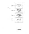
図1、図2及び図3は、ストレージ部材12と、第1キャップ14と、第2キャップ16とを含む第1の例示的なストレージ装置10を示す。図示の実施形態において、第1キャップ14及び第2キャップ16のそれぞれは、ストレージ部材12に解放可能に装着されている。 1, 2, and 3 illustrate a first
ストレージ部材12は、長手方向軸13と、第1端部20と、第2端部22と、周壁26、第1開口部28、第2開口部30、パセッジウェイ32、分離壁34及び複数の孔36を画定する本体24とを有する。パセッジウェイ32は、ストレージ部材12を通して第1開口部28から第2開口部30まで延在し、且つ第1端部20から分離壁34まで延在する第1部分38と、第2端部22から分離壁34まで延在する第2部分40とを有する。第1部分38は、第1内径39を有する。第2部分40は、第2部分40が第2端部22から分離壁34までテーパー化される(例えば、部分的な円錐を生成する)ように、第1内径39余小さい、分離壁34における第2内径41と、第1内径39に等しい、第2端部22における第3内径43とを有する。図示の実施形態において、第2部分40は、本明細書において更に詳細に記述するように、埋植可能な医療装置を収容するようにサイズ設定及び構成されている。分離壁34は、第1端部20と、第1端部20に相対的に近接した状態で位置決めされた第2端部22との間の場所においてパセッジウェイ32内に延在する。分離壁34は、第2部分40の第2内径41より小さい内径45を有するスルーホール42を画定する。複数の孔36のそれぞれの孔は、分離壁34を通して延在し、且つストレージ部材12を通過した流体が、パセッジウェイ40の第2部分内に配設された医療装置の外側及び内側表面上においてスルーホール42及び/又は複数の孔36を通過し得るように、パセッジウェイ32の第1部分38とパセッジウェイ32の第2部分40との間のアクセスを提供する。複数の孔36のそれぞれの孔は、複数の孔36の隣接する孔から等しく離隔され、且つ複数の孔36の他の孔に対して周壁26から同一の距離に配設されている。 The
ストレージ部材12は、特定の構造的構成を有するものとして示されているが、ストレージ部材は、任意の適切な構造的構成を有することが可能であり、且つストレージ部材のための適切な構造的構成の選択は、ストレージ部材内に保存されることを意図された埋植可能な医療装置のタイプを含む様々な考慮事項に基づいたものであり得る。例えば、パセッジウェイ32は、第1部分38及び第2部分40を有するものとして示されているが、ストレージ部材の本体によって画定されたパセッジウェイは、1つ、少なくとも1つ、2つ、複数、3つ、4つ及び特定の実施形態に適切であるとみなされる任意の他の数などの任意の適切な数の部分を有することができる。第2部分40は、第1内径39より小さい、分離壁34における第2内径41と、第1内径39に等しい、第2端部22における第3内径43とを有するものとして図示されているが、第2部分は、任意の適切な内径を有することができる。例えば、第2部分は、第1部分の第1内径に等しい、それ未満、それ超若しくはほぼそれに等しい、分離壁における第2内径並びに/又は第1内径に等しい、それ未満、それ超若しくはほぼそれに等しい、第2端部における第3内径を有することができる。分離壁34は、第1端部20に相対的に近接した状態で位置決めされるものとして示されているが、分離壁は、ストレージ部材の第1及び第2端部間の任意の適切な場所に位置決めすることができる。例えば、分離壁は、第1及び第2端部間でストレージ部材の中心に配置することが可能であるか、又はストレージ部材の第2端部に相対的に近接した状態で位置決めすることができる。ストレージ部材12は、複数の孔36のそれぞれの孔が、複数の孔36の隣接する孔から等しく離隔され、且つ複数の孔36の他の孔に対して周壁26から同一の距離に配設されるように、複数の孔36を画定するものとして図示されているが、ストレージ部材は、任意の適切な向きで位置決めされた任意の適切な数の孔を含むことができる。分離壁上に画定するためにストレージ部材の本体に適切であるとみなされる孔の数の例は、1つ、少なくとも1つ、2つ、複数、3つ、4つ、5つ、5つ超、10個超及び特定の実施形態に適切であるとみなされる任意の他の数を含む。複数の孔を配置するために適切であるとみなされる位置の例は、複数の孔のそれぞれの孔が、複数の孔の隣接する孔から等しく離隔されるか又は不規則に離隔され、且つ複数の孔の他の孔に対して周壁から同一の距離又は変化した距離に配設されるようなものを含む。 Although
第1キャップ14及び第2キャップ16のそれぞれは、ストレージ部材12に解放可能に装着されるようにサイズ設定及び構成されている。第1キャップ14は、ストレージ部材12の第1端部20に解放可能に装着され、且つ第2キャップ16は、ストレージ部材の第2端部22に解放可能に装着されている。ストレージ部材12に装着された際、第1キャップ14及び第2キャップ16のそれぞれは、ストレージ部材12によって画定されたパセッジウェイ32を封止している。図示の実施形態において、第1キャップ14及び第2キャップ16のそれぞれは、ストレージ部材12と第1及び第2キャップ14、16との間の解放可能な装着を実現するために、ストレージ部材12によって画定されたねじ山と結合するねじ山を画定する。 Each of first cap 14 and
第1キャップ14は、ストレージ部材12に結合可能に装着されるものとして示されており、且つ第2キャップ16は、ストレージ部材12に結合可能に装着されるものとして示されているが、第1キャップ及び第2キャップは、任意の適切な装着の技法又は方法を使用することにより、ストレージ部材に装着することが可能であり、且つキャップとストレージ部材との間の適切な装着の技法又は方法の選択は、キャップ及び/又はストレージ部材を形成している1つ又は複数の材料を含む様々な考慮事項に基づいたものであり得る。キャップとストレージ部材との間、ストレージ部材と任意の他のコンポーネントとの間、ローディング部材と任意の他のコンポーネントとの間及び/又は本明細書において記述されている2つのコンポーネント間で適切であるとみなされる装着の技法及び方法の例は、ねじ接続、(例えば、キャップの装着時、ストレージ装置内に保存されている埋植可能医療装置の破壊を回避するために)ストレージ部材の回転を回避するためにストレージ部材の外部表面上に配設されたねじ山を使用したねじ接続、スナップフィット装着の使用、1つ又は複数のコネクタ、1つ又は複数の結合スロット及び突起、1つ又は複数の封止された結合、テーパー化された装着(例えば、モールステーパー)並びに特定の用途に適切であるとみなされる任意の装着の技法又は方法の使用を含む。 Although the first cap 14 is shown as being connectably attached to the
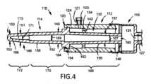
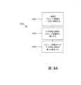
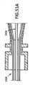
図4及び図5は、別の例示的なストレージ装置110を示す。ストレージ装置110は、以下において詳述されている内容を除いて、図1、図2及び図3に示され、且つ上述したストレージ装置10に類似している。ストレージ装置110は、ストレージ部材112と、第1キャップ114と、第2キャップ116とを含む。図示の例において、第1キャップ114及び第2キャップ116のそれぞれは、ストレージ部材112と第1及び第2キャップ114、116との間の解放可能なスナップフィット装着を実現するために、ストレージ部材112によって画定された構造と結合する構造を画定する。 4 and 5 illustrate another
図示の実施形態において、ストレージ部材112は、本体124から延在するポート121と、ポート121に装着された第1二方弁123とを含む。加えて、第2キャップ116は、第2二方弁127と連通している第2キャップ116の本体を通して延在するパセッジウェイ125を画定する。この構造的構成は、ストレージ装置110内に保存されている埋植可能な医療装置を消毒及び/又はすすぎ落しする、埋植可能な医療装置の消毒、保存、すすぎ落し及び/又はローディングの複雑性を減少させ、且つストレージ装置内に位置決めされることを意図された埋植可能な医療装置のハンドリングと関連するリスクを極小化するためのメカニズムを提供する。一代替実施形態において、ポート121、第1二方弁123、パセッジウェイ125及び/又は第2二方弁127は、省略することができる。 In the illustrated embodiment,
図示の実施形態において、第1キャップ114は、ストレージ部材112の第1端部120に解放可能に装着され、且つストレージ部材112によって画定されたパセッジウェイ132内に部分的に延在する装置ガード146を含む。装置ガード146は、長手方向軸147と、第1端部148と、第2端部150と、ベース154、第1突起156、第2突起158及び凹部160を画定する本体152とを有する。ベース154は、第1端部148と第2端部150との間に配設され、且つストレージ部材112のパセッジウェイ132内に解放可能に装着されるようにサイズ設定及び構成されている。図示の実施形態において、ベース154は、外径155と、第1側部162と、第2側部164とを有し、且つ装置ガード146とストレージ部材112との間のスナップフィット装着を使用してパセッジウェイ132内でストレージ部材112に解放可能に装着されるようにサイズ設定及び構成されている。従って、ストレージ部材112及び装置ガード146は、ストレージ部材112と装置ガード146との間の解放可能なスナップフィット装着を実現する結合構造を画定する。 In the illustrated embodiment, the
第1突起156は、第1側部162から第1端部148まで延在し、且つ第2突起158は、第2側部164から第2端部150まで延在する。第1突起156は、ベース154から第1端部148までテーパー化される外径157を有し、これは、第1突起156とストレージ部材112との間で埋植可能な医療装置を位置決めするためのメカニズムを提供する。第2突起158は、ベース154における第1外径149と、ベース154と第2端部150との間における第2外径151と、第2端部150における第3外径153とを有する。第2外径151は、第1外径149より小さく、且つ第3外径153は、第2外径151より小さい。凹部160は、第1端部148から第2端部150に向かって凹部ベース166まで延在し、且つ更に詳細に後述するように、供給システムの一部分を受け入れるようにサイズ設定及び構成されている。凹部160は、第1部分168と、第2部分170と、第3部分172とを有する。第1部分168は、第1端部148から第2部分170まで増大する内径167を有する。第2部分170は、第1部分168から第3部分172までテーパー化される内径169を有する。第3部分172は、第2部分170の内径169より小さい内径171を有する。第1部分168及び第2部分170のそれぞれは、部分的な円錐構成を有し、且つ第3部分172は、本明細書において更に詳細に記述するように、第3部分172内に配設された際、供給システムの一部分が装置ガード146に対して回転的に固定されるように、供給システムの一部分(例えば、先端1516)と結合するようにサイズ設定及び構成されている。図示の実施形態において、第3部分172は、本明細書において更に詳述するように、供給システムの先端の一部分(例えば、先端1516の平坦な表面1572)と結合するようにサイズ設定及び構成された、凹部ベース166まで第2部分170から延在する平坦な表面173を画定する。ストレージ部材112に装着された際、装置ガード146は、第1突起156が分離壁134のスルーホール142を通して延在するように位置決めされている。使用時、装置ガード146は、本明細書において更に詳述するように、ストレージ部材を通した供給システムの前進に対する機械的なストップとして機能する。 The
装置ガード146は、特定の構造的構成を有するものとして示されているが、装置ガードは、任意の適切な構造的構成を有することが可能であり、且つ装置ガードのための適切な構造的構成の選択は、装置ガードがそのコンポーネントであるストレージ装置を使用して埋植されることを意図されている埋植可能な医療装置のタイプを含む様々な考慮事項に基づいたものであり得る。例えば、装置ガード146は、単一コンポーネントとして示されているが、装置ガードは、互いに解放可能に装着された又は固定方式で装着された複数のコンポーネント(例えば、ベース、第1突起、第2突起)として形成することが可能である一方、第1突起は、その長さに沿って一定の外径を有することが可能であり、第2突起は、その長さに沿って一定の外径を有することが可能であり、且つ/又は第1部分は、第1端部から第2端部まで一定である内径を有することができる。第1部分168及び第2部分170のそれぞれは、部分的な円錐構成を有するものとして示されており、且つ第3部分172は、第2部分170から凹部ベース166まで延在する平坦な表面173を有するものとして示されているが、装置ガードによって画定される凹部は、任意の適切な構成を有することができる。例えば、凹部は、供給システムの任意の適切な部分(例えば、先端の一部分、先端全体)を受け入れるようにサイズ設定及び構成された任意の構造的構成を画定することが可能であり、且つ/又は装置ガード内に配設された際、装置ガードに対して供給システムの一部分を回転可能に固定することができる。装置ガード146は、ストレージ部材112に解放可能に装着されるものとして示されているが、本明細書において記述されているもの(例えば、装置ガード715、装置ガード1714)などの任意の装置ガードは、ストレージ部材に解放可能に装着することができる。 Although the
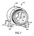
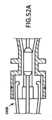
図6及び図7は、別の例示的なストレージ装置210を示す。ストレージ装置210は、以下において詳述されている内容を除いて、図1、図2及び図3に示され、且つ上述したストレージ装置10に類似している。ストレージ装置210は、ストレージ部材212と、第1キャップ214と、第2キャップ216とを含む。 6 and 7 illustrate another
図示の実施形態において、第2部分240は、第2部分240が分離壁234から第2端部222まで一定の内径241を有する(例えば、円筒体を生成する)ように、第1内径239に等しい分離壁234における第2内径241を有する。加えて、ストレージ部材212の本体224によって画定された複数の孔236のそれぞれの孔は、複数の孔236の隣接する孔から等しく離隔されておらず、且つ複数の孔236の他の孔に対して周壁226から異なる距離に配設されている。ストレージ部材212の本体224は、周壁226から延在する第1及び第2突起276、278と、第1突起276を通して延在する第1パセッジウェイ280と、第2突起278を通して延在する第2パセッジウェイ282とを画定する。突起276、278及びパセッジウェイ280、282は、本明細書において更に上述したように、ストレージ部材212がローディング部材及び/又はガイド部材に解放可能に装着され得るように、ローディング部材及び/又はガイド部材と結合するようにサイズ設定及び構成されている。ストレージ部材212は、ローディング部材及び/又はガイド部材に対する解放可能な装着を実現するために特定の構造的構成を含むものとして示されているが、このような解放可能な装着を実現するために任意の適切な構造を使用することができる。本明細書において記述されているストレージ部材の任意の実施形態は、更に詳細に本明細書において記述されているように、ストレージ部材がローディング部材及び/若しくはガイド部材に解放可能に装着され得るように、且つ/又はガイドシステムと共に使用され得るように、1つ又は複数の突起(例えば、突起276、278)及び1つ又は複数のパセッジウェイ(パセッジウェイ280、282)を任意選択により含むことができる。 In the illustrated embodiment, the
図示の実施形態において、第2キャップ216は、ストレージ部材212の第2端部222に解放可能に装着されている。第2キャップ216は、長手方向の軸283と、第1端部284と、第2端部286と、第2キャップ216内に延在する凹部290を画定する本体288とを有する。凹部290は、第1部分292と、第2部分294とを有し、且つ凹部ベース296まで延在する。第1部分292は、第1端部284から第2端部286に向かって延在し、且つ第1内径291を有する。第2部分294は、第1部分292から凹部ベース296まで延在し、且つ第1部分292から凹部ベース296までテーパー化される第2内径293を有する。 In the illustrated embodiment,
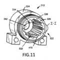
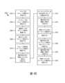
図8、図9、図10、図11、図12、図13及び図14は、別の例示的なストレージ装置310を示す。ストレージ装置310は、以下において詳述されている内容を除いて、図6及び図7に示され、且つ上述したストレージ装置210に類似している。ストレージ装置310は、ストレージ部材312と、第1キャップ314と、第2キャップ316と、第1一方弁410と、第2一方弁412と、ディフューザ414とを含む。 8, 9, 10, 11, 12, 13, and 14 illustrate another
図示の実施形態において、ストレージ部材312の第2部分340の内径は、部分的に複数の孔336を遮断するように、パセッジウェイ332の第2部分340内に周壁326を位置決めする分離壁334における第2内径341を有する。図10、図11及び図12に示されているように、ストレージ部材312の本体324は、複数の凹部416を画定する。複数の凹部416のそれぞれの凹部は、凹部ベース418まで周壁326内に延在し、且つ分離壁334から第2端部322に向かって延在する。図示の実施形態において、複数の凹部416のそれぞれの凹部は、第2端部322まで延在する。複数の凹部416のそれぞれの凹部は、複数の孔336の1つの孔と連通しており、且つ凹部ベース418における分離壁334における第1幅415と、第1幅415より大きい、凹部ベース418における分離壁334と第2端部322との間の第2幅417とを有する。複数の孔336の孔に隣接し、且つそれと連通するように、複数の凹部416のそれぞれの凹部を位置決めすることにより、第1一方弁410から第2一方弁412に向かってストレージ部材312を通過した流体は、ストレージ部材312内に配設された任意の埋植可能な医療装置に接触する流体の量を増大させるために、複数の孔336を通して且つ複数の凹部416内で流れることができる。ストレージ部材312の本体324によって画定されたスルーホール342は、更に詳細に本明細書において記述するように、ディフューザ414の一部分を受け入れるようにサイズ設定及び構成されている。 In the illustrated embodiment, the inner diameter of the
複数の凹部416のそれぞれの凹部は、分離壁334から第2端部322まで延在するものとして、複数の孔336の1つの孔と連通しているものとして、且つ凹部ベース418における分離壁334における第1幅415と、第1幅415より大きい、凹部ベース418における分離壁334と第2端部322との間の第2幅417とを有するものとして示されているが、それぞれの凹部は、任意の適切な構造的構成を有することができる。ストレージ部材に含まれるそれぞれの凹部のための適切な構造的構成の選択は、ストレージ部材内に配設されることを意図された埋植可能な医療装置の構造的構成を含む様々な考慮事項に基づいたものであり得る。例えば、ストレージ部材は、特定の実施形態について適切であるとみなされる、1つ、少なくとも1つ、2つ、複数、3つ、4つ、5つ、5つ超、10個超及び任意の他の数などの任意の適切な数の凹部を画定することができる。ストレージ部材上に含まれる凹部は、ストレージ部材の任意の適切な長さだけ延在することができる。例えば、1つの凹部又は複数の凹部のそれぞれの凹部は、分離壁からストレージ部材の第2端部まで、分離壁から分離壁と第2端部との間の場所まで、分離壁と第2端部との間の場所から第2端部まで、分離壁と第2端部との間の第1場所から第1場所と第2端部との間の第2場所まで、且つ特定の実施形態について適切であるとみなされるストレージ部材の任意の他の長さだけ延在することができる。ストレージ部材上に含まれる凹部は、その長さに沿って任意の適切な幅を有することができる。例えば、1つ凹部又は複数の凹部のそれぞれの凹部は、凹部ベースにおける第1端部における(例えば、分離壁における)第1幅と、第1幅超、それ未満、それに等しい又はほぼそれに等しい、凹部ベースにおける第2端部における(例えば、分離壁と第2端部との間の)第2幅とを有することができる。ストレージ部材上に含まれる凹部は、特定の実施形態について適切であるとみなされる、湾曲した、立方体形の、プリズム形の及び任意の他の構造的構成などの任意の適切な構造的構成を有することができる。 Each recess of the plurality of
図示の実施形態において、第2キャップ316は、ストレージ部材312の第2端部322に解放可能に装着されている。第2キャップ316のパセッジウェイ390は、第1部分392と、第2部分394と、第3部分396と、第4部分398とを有する。第1部分392は、第1端部384から第2端部386に向かって延在し、且つ第1内径391を有する。第2部分394は、第1部分392から第3部分396まで延在し、且つ第1部分392から第3部分396までテーパー化される第2内径393を有する。第3部分396は、第2部分394から第4部分398まで延在し、且つ第2部分394から第4部分398までテーパー化される内径395を有する。第4部分398は、第3部分396から第2端部386まで延在し、且つ更に詳細に本明細書において記述されるように、流体がパセッジウェイ390を通して第2一方弁412まで通過することを許容するようにサイズ設定及び構成された内径397を有する。 In the illustrated embodiment,
図示の実施形態において、第1キャップ314は、第1端部420と、第2端部422と、パセッジウェイ426及び凹部428を画定する本体424とを有する。パセッジウェイ426は、第1端部420から凹部428まで延在し、且つ流体がパセッジウェイ426を通過することを許容するようにサイズ設定及び構成されている。第1一方弁410が第1キャップ314の第1端部420に解放可能に装着され、且つ第2一方弁412が第2キャップ316の第2端部386に解放可能に装着されている。第1及び第2一方弁410、412のそれぞれは、第1開口部430と、第2開口部432とを有し、且つ流体が1つの方向において弁を通過することを許容するように適合されている。図示の実施形態において、第1一方弁410は、流体が第1開口部430から第2開口部432まで弁を通過することを許容するように適合され、且つ第2一方弁412は、流体が第2開口部432から第1開口部430まで弁を通過することを許容するように適合されている。代わりに、第1一方弁は、流体が第1開口部から第2開口部まで又は第2開口部から第1開口部まで弁を通過することを許容するように適合させることが可能であり、且つ/又は第2一方弁は、流体が第1開口部から第2開口部まで又は第2開口部から第1開口部まで弁を通過することを許容するように適合させることができる。代替実施形態において、第1一方弁及び/又は第2一方弁は、更に詳細に本明細書において記述するように、ストレージ装置及び/又はローディング装置から省略することが可能であり、第1キャップは、凹部を画定することが可能であり、且つパセッジウェイの包含を省略することが可能であり、第2キャップは、凹部を画定することが可能であり、且つパセッジウェイの包含を省略することが可能であり、及び/又はローディング部材は、凹部を画定することが可能であり、且つパセッジウェイの包含を省略することができる。代わりに、第1一方弁及び/又は第2一方弁は、より詳細に本明細書において記述するように、ストレージ装置及び/又はローディング装置から省略することが可能であり、且つ流体が1つ又は複数のパセッジウェイを通して通過することができないように、第1キャップによって画定されたパセッジウェイ、第2キャップによって画定されたパセッジウェイ及び/又はローディング部材によって画定されたパセッジウェイを封止するために、キャップを第1キャップの第1端部、第2キャップの第2端部及び/又はローディング部材の第2端部上に配設することができる。代わりに、第1一方弁及び/又は第2一方弁は、本明細書において更に詳述するように、ストレージ装置及び/又はローディング装置から省略することが可能であり、且つ第1二方弁及び/又は第2二方弁は、任意の他の一方弁の代わりに、ストレージ装置及び/又はローディング装置内に含まれ得る。代わりに、ストレージ装置内に含まれる第1一方弁及び/又は第2一方弁は、キャップに永久的に固定することも可能であり、ストレージ装置のキャップ又は他のコンポーネントによって画定された凹部内に配設することもできる。 In the illustrated embodiment,
ディフューザ414は、パセッジウェイ332の第1部分及び分離壁334のスルーホール342内に解放可能に配設されている。図13及び図14に示されているように、ディフューザ414は、第1端部434と、第2端部436と、ベース438と、フレーム440とを有する。ベース438は、第2端部436から第1端部に向かってフレーム440まで延在し、且つ分離壁334のスルーホール342によって受け入れられるようにサイズ設定及び構成されている。ベース438は、(例えば、ディフューザがスルーホール342を封止するように)スルーホール342の内径に等しい外径439を有する。但し、代替実施形態は、スルーホールの内径未満、それ超又はほぼそれに等しい外径を有するベースを有するディフューザを含むことができる。ストレージ部材312及びディフューザ414は、ディフューザ414のベース438とストレージ部材312の分離壁334との間のスナップフィット装着を実現する結合構造を画定する。フレーム440は、ベース438から第1端部434まで延在し、且つ流体が使用時にフレーム432を通過することを許容するようにサイズ設定及び構成された複数の開口部446を画定する複数の支柱442を有する。ディフューザ414は、ディフューザ414のベース438がスルーホール342を封止していない実施形態において、流体が複数の孔336及び/又はスルーホール342を通過し得るように、使用時にストレージ部材312を通過した流体を供給するためのメカニズムを提供する。代替実施形態において、ディフューザは、本明細書において更に詳述するように、ストレージ装置及び/又はローディング装置から省略することができる。
ディフューザ414は、特定の構造構成を有するものとして、且つストレージ部材の第1部分内に解放可能に配設されるものとして示されているが、ディフューザは、任意の適切な構造的構成を有することが可能であり、且つ任意の適切な場所においてストレージ部材内に位置決めすることができる。ディフューザのための適切な構造的構成及びストレージ部材内にディフューザを位置決めするための適切な場所の選択は、ディフューザが配設されているストレージ部材の構造的構成を含む様々な考慮事項に基づいたものであり得る。ストレージ部材内にディフューザを位置決めするための適切な場所の例は、ディフューザが、ストレージ装置の第1部分内に解放可能に配設されるようなもの、ストレージ装置の第2部分内に解放可能に配設されるようなもの、永久的又は解放可能にストレージ装置のキャップ(例えば、第1キャップ、第2キャップ)に装着されるようなもの、永久的又は解放可能に(例えば、パセッジウェイの第1部分内、パセッジウェイの第2部分内において)ストレージ部材に装着されるようなもの並びに特定の実施形態について適切であるとみなされる任意の他の場所を含む。 Although the
ストレージ装置310は、埋植可能な医療装置の消毒、保存、すすぎ落し及び/又はローディングの複雑さを減少させ、且つ埋植することを意図された埋植可能な医療装置のハンドリングと関連するリスクを極小化するためのメカニズムを提供する。例えば、ストレージ装置310は、消毒、保存、すすぎ落し及び/又はローディング時に埋植可能な医療装置との相互作用を低減する閉鎖システムを使用して埋植可能な医療装置を消毒、保存、すすぎ落し及び/又はローディングするためのメカニズムを提供する。
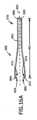
図15、図16及び図16Aは、別の例示的なストレージ装置510を示す。ストレージ装置510は、以下において詳述されている内容を除いて、図8、図9、図10、図11、図12、図13及び図14に示され、且つ上述したストレージ装置310に類似している。ストレージ装置510は、ストレージ部材512と、第1キャップ514と、第2キャップ516と、第1一方弁610と、第2一方弁612と、ディフューザ614と、埋植可能な医療装置650と、ローディングプラー652とを含む。 15, 16, and 16A illustrate another
図示の実施形態において、埋植可能な部材装置650は、フレーム654と、フレーム654に装着された材料656とを含む。埋植可能な医療装置650は、流体がストレージ部材512の第1部分538を通して且つ複数の孔536及び分離壁534のスルーホール542を介して第2部分540内に通過した際、流体が埋植可能な医療装置650の外側及び内側表面上を通過し得るように、ストレージ部材512の第2部分540内に配設されている。 In the illustrated embodiment,
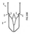
図示の実施形態において、ローディングプラー652は、埋植可能な医療装置650に解放可能に装着され、且つストレージ部材512及び第2キャップ516のそれぞれ内に部分的に配設されている。ローディングプラー652は、長手方向軸657と、第1端部658と、第2端部660と、長さ661と、第1屈曲部664、第2屈曲部666、第3屈曲部668及び第4屈曲部670を画定する本体662とを有する。ローディングプラー657は、本明細書において詳述しているように、供給システムの細長い部材によって画定された切欠きと結合するようにサイズ設定及び構成されている。ローディングプラー652が埋植可能な医療装置650に解放可能に装着された際、ローディングプラーが、埋植可能な医療装置650のフレーム654の一部分を部分的に取り囲む2つのフック付き端部672、674を画定するように、第1屈曲部664は、第1端部658と第2屈曲部666との間の第1端部658の近傍に位置決めされ、且つ第4屈曲部670は、第2端部660と第3屈曲部668との間の第2端部660の近傍に位置決めされている。第1フック付き端部672は、ローディングプラー652の長手方向軸657に対して第2フック付き端部674とは反対側に位置決めされている。ローディングプラー652がU字形状の部材676を画定するように、第2屈曲部666は、第1屈曲部664と第3屈曲部668との間に配設され、且つ第3屈曲部668は、第2屈曲部666と第4屈曲部670との間に配設されている。ローディングプラー652は、第1の圧縮されていない又は開放された構成と、第2の圧縮された又は閉鎖された構成との間で移動可能である。閉鎖構成において、ローディングプラー652は、ローディングプラー652が埋植可能な医療装置に解放可能に装着され得るように、埋植可能な医療装置の外径より小さい、フック付き端部672、674間に配設された幅を有する。閉鎖構成において、図16Bに示されているように、ローディングプラー652の一部分(例えば、フック付き端部672、674)は、軸方向の力がローディングプラー652に印加された際、ローディングプラー652が、埋植可能な医療装置650に軸方向の力を印加する能力を有するように、埋植可能な医療装置650のフレームによって画定された1つ又は複数の開口部651内に配設されている。開放構成において、ローディングプラー652は、ローディングプラーが埋植可能な医療装置から自由になるように、埋植可能な医療装置の外径より大きい、フック付き端部672、674間に配設された幅を有する。図示の実施形態において、ローディングプラー652は、開放構成に付勢されている。 In the illustrated embodiment, a
ローディングプラー652は、特定の構造的構成を有するものとして示されているが、ローディングプラーは、本明細書において更に詳述するように、埋植可能な医療装置に対する解放可能な装着を提供し、且つ埋植可能な医療装置をストレージ装置及び/又はローディング装置を通して前進させる、能力を有する任意の適切な構造的構成を有することができる。ローディングプラーのための適切な構造的構成の選択は、ローディングプラーが装着されることを意図されている埋植可能な医療装置の構造的構成などの様々な考慮事項に基づいたものであり得る。例えば、ローディングプラー652は、ローディングプラー652の長手方向軸657に対して第2フック付き端部674とは反対側に位置決めされた第1フック付き端部672を有するものとして示されているが、第1フック付き端部は、ローディングプラーの長手方向軸に対して第2フック付き端部に対して任意の適切な場所に位置決めすることができる。ローディングプラー652は、4つの屈曲部を画定するものとして示されているが、ローディングプラーは、任意の数の屈曲部を画定することができる。画定されるローディングプラーについて適切であるとみなされる屈曲部の数の例は、1つ、少なくとも1つ、2つ、複数、3つ、4つ、5つ、5つ超及び特定の実施形態について適切であるとみなされる任意の他の数を含む。例えば、ローディングプラーは、第1及び第2フック付き端部を画定するために第1及び第2屈曲部のみを画定することが可能であり、且つ第1フック付き端部が第2フック付き端部とは反対側に位置決めされるように、第1屈曲部と第2屈曲部との間に画定されたカーブを含むことができる。代わりに、ローディングプラーは、第1及び第2フック付き端部を画定するために、第1、第2及び第3屈曲部のみを画定することも可能であり、且つ第3屈曲部は、第1フック付き端部が第2フック付き端部とは反対側に位置決めされるように、第1屈曲部と第2バンドとの間に画定することもできる。 Although loading
ローディングプラー652は、任意の適切な材料から且つ任意の製造の方法を使用して形成することが可能であり、且つ適切な材料及び製造方法の選択は、ローディングプラーが解放可能に装着されることを意図された埋植可能な医療装置を形成する材料を含む様々な考慮事項に基づいたものであり得る。ローディングプラーを形成するために適切であるとみなされる材料の例は、生体適合性材料、生体適合性を有し得る材料、金属、形状記憶合金、Nitinol、プラスチック及び特定の実施形態について適合しているとみなされる任意の他の材料を含む。図示の実施形態において、ローディングプラーは、Nitinolから形成されている。
図17は、例示的なローディング装置710を示す。ローディング装置710は、ローディング部材712と、第1キャップ714と、第2キャップ716と、埋植可能な医療装置718と、ローディングプラー720とを含む。埋植可能な医療装置718は、以下に詳述されている内容を除いて、図15及び図16に示され、且つ上述した埋植可能な医療装置650に類似している。ローディングプラー720は、以下において詳述されている内容を除いて、図15及び図16に示され、且つ上述したローディングプラー652に類似している。 FIG. 17 shows an
図示の実施形態において、ローディング部材712は、長手方向軸721と、第1端部722と、第2端部724と、第1開口部728、第2開口部730及びパセッジウェイ732を画定する本体726とを有する。パセッジウェイ732は、第1開口部728から第2開口部730まで延在し、且つ第1部分734と、第2部分736と、第3部分738と、第4部分740とを有する。パセッジウェイ732は、埋植可能な医療装置718を収容するようにサイズ設定及び構成されている。第1部分734は、第1端部722から第2部分736まで延在し、且つ内径735を有する。第2部分736は、第1部分734から第3部分738まで延在し、且つ第1部分734から第3部分738までテーパー化される内径737を有する。第3部分738は、第2部分736から第2端部に向かって延在する。図示の実施形態において、第3部分738は、第2部分736から第2端部724まで延在し、長手方向軸721に直交する平面に沿って取得された第1断面構成(例えば、円形の断面構成)を有し、且つ第1部分734の内径735より小さい内径739を有する。第4部分740は、第3部分738(例えば、第2端部724と第2部分736との間の場所)から第2端部724まで延在し、長手方向軸721に直交する平面に沿って取得された第2断面構成(例えば、細長い断面構成、矩形の断面構成)を有し、且つ第3部分738の内径739より大きく、且つパセッジウェイ732の第1部分734の内径735より小さい、(長手方向軸721に直交する平面上において計測された)幅741を有する。使用時、ローディングプラー720がパセッジウェイ732を通して引っ張られた際、パセッジウェイ732の第2部分736を通して移動するのに伴い、ローディングプラー720は、その閉鎖構成にあり、且つ埋植可能な医療装置718は、その圧縮された構成にある。ローディングプラー720がパセッジウェイ732の第4部分に到達した際、ローディングプラーは、その開放構成に膨張する一方、埋植可能な医療装置718は、その圧縮された構成において留まっている。埋植可能な医療装置718は、パセッジウェイ732の第1部分734内に配設されるものとして示されているが、埋植可能な医療装置は、ローディング部材の任意の適切な部分内に配設することができる。ローディング装置内に位置決めされることを意図された埋植可能な医療装置の構造的構成に応じて、パセッジウェイは、任意の適切な構造的構成を有することができる。例えば、パセッジウェイの様々な部分は、円形、細長い、楕円、矩形などの任意の適切な断面構成を有することが可能であり、パセッジウェイの一部分は、その部分の長さに沿って、一定の内径、部分の長さに沿って変化する内径(例えば、第1端部から第2端部又は第2端部に向かう第1端部と第2端部との間の場所に向かってテーパー化されている、第1内径が第1端部とショルダとの間であり、且つ第1内径より大きい第2内径がショルダと第2端部との間であるように、その部分内でショルダを画定する)又は特定の実施形態について適合するとみなされる任意の他の構成を有することができる。 In the illustrated embodiment,
第2キャップ716は、ローディング部材712の第2端部724に解放可能に装着され、且つ第1端部742と、第2端部744と、凹部748及び凹部ベース750を画定する本体746とを有する。凹部748は、第1部分752と、第2部分754とを有する。第1部分752は、第1内径753を有し、且つ第2部分754は、第1部分752の第1内径753より小さい第2内径755を有する。第2部分754は、ローディングプラー720の一部分を受け入れるようにサイズ設定及び構成されている。第2キャップ716及びローディング部材712は、第2キャップ716とローディング部材712との間におけるスナップフィット装着を実現する結合構造を画定する。 A
図示の実施形態において、第1キャップ714は、ローディング部材712の第1端部722に解放可能に装着され、且つローディング部材712によって画定されたパセッジウェイ732内に部分的に延在する、装置ガード715を含む。装置ガード715は、第1端部756と、第2端部758と、ベース762、側壁764、突起766及び突起766内に延在する凹部768を画定する本体760とを有する。ベース762及び側壁764は、ローディング部材712の一部分を受け入れるようにサイズ設定及び構成された空洞770を協働して画定する。突起766は、ベース762から空洞770を通して、空洞770の外部である環境まで延在する。凹部768は、第2端部758から第1端部756に向かって凹部ベース769まで延在する。凹部768は、本明細書において更に詳述されているように、供給システムの一部分を受け入れるようにサイズ設定及び構成されている。装置ガード715は、ローディング部材712に解放可能に装着されるものとして示されているが、本明細書において記述されているものなどの任意の適切な装置ガード(例えば、装置ガード146、装置ガード1714)又は本明細書において記述されているものなどのキャップ(例えば、キャップ14)をローディング部材に解放可能に装着することができる。代替実施形態は、供給システムの先端を上回る又はそれと等しい長さを有するか、又は供給システムの先端の一部分を受け入れるようにサイズ設定及び構成された第1端部上の開口部又は中空の延在を画定する、突起を含む装置ガードを含むことができる。 In the illustrated embodiment, the
図示の実施形態において、ローディングプラー720は、埋植可能な医療装置718に解放可能に装着され、且つローディング部材712(例えば、パセッジウェイ732)及び第2キャップ716のそれぞれ内に部分的に配設されている。第1及び第2トラックを含む実施形態では、本明細書において更に詳述されているように、ローディングプラーは、ローディング部材、第1トラック及び第2トラックによって画定されたパセッジウェイ内に部分的に配設されている。 In the illustrated embodiment,
任意選択により、ローディング装置は、ポート(例えば、ポート121)と、第1二方弁(例えば、弁123)と、第1キャップ上に画定されたパセッジウェイ(例えば、パセッジウェイ426)と、第2キャップ上に画定されたパセッジウェイ(例えば、パセッジウェイ125)と、第2二方弁(例えば、弁127)とを含むことができる。これらの実施形態において、埋植可能な医療装置は、ローディング部材(例えば、パセッジウェイの第1部分)内に位置決めすることが可能であり、且つキャップは、記述されているように、ローディング部材上に位置決めすることができる。この結果、既に消毒済みではない場合、第1及び第2二方弁及び弁に装着された任意の適切なコンポーネントを使用してローディング部材に消毒材料を通すことにより、埋植可能な医療装置を消毒するために、消毒材料を、ポートを使用してローディング部材に通すことができる。消毒後、第1及び第2二方弁及び弁に装着された任意の適切なコンポーネントを使用してローディング部材にすすぎ落し材料を通すことにより、埋植可能な医療装置をすすぎ落しするために、ポートを使用してローディング部材にすすぎ落し材料を通すことができる。任意選択により、第1及び第2二方弁及び弁に装着された任意の適切なコンポーネントを使用してローディング部材に保持材料を通すことにより、埋植可能な医療装置を保存するために、保持材料を、ポートを使用してローディング部材に通すことができる。この構造的構成は、本明細書において記述されているように、供給システムが、埋植可能な医療装置を供給するために使用される時点まで、埋植可能な医療装置がいずれのコンポーネントによっても接触されないように、埋植可能な医療装置を消毒、すすぎ落し及び保存するためのメカニズムを提供する。 Optionally, the loading device includes a port (e.g., port 121), a first two-way valve (e.g., valve 123), a passageway defined on the first cap (e.g., passageway 426), and a second cap. The passageway defined above (eg, passageway 125) and a second two-way valve (eg, valve 127) can be included. In these embodiments, the implantable medical device can be positioned within the loading member (e.g., the first portion of the passageway) and the cap is positioned on the loading member as described. Can be positioned. As a result, if not already sterilized, the implantable medical device can be removed by passing sterilizing material through the loading member using the first and second two-way valves and any suitable components attached to the valves. For disinfection, disinfection material can be passed through the loading member using the port. After disinfection, rinsing the implantable medical device by passing rinsing material through the loading member using the first and second two-way valves and any suitable components attached to the valves; The port can be used to pass rinse material through the loading member. optionally, retaining the implantable medical device by passing a retaining material through the loading member using the first and second two-way valves and any suitable components attached to the valves; Material can be passed through the loading member using the port. This structural configuration ensures that the implantable medical device is not affected by any of its components until the point at which the delivery system is used to deliver the implantable medical device, as described herein. Provides a mechanism for disinfecting, rinsing and storing implantable medical devices from contact.
ローディング装置710は、埋植可能な医療装置の消毒、すすぎ落し及び/又はローディングの複雑さを減少させ、且つ埋植することを意図されている埋植可能な医療装置のハンドリングと関連するリスクを極小化するためのメカニズムを提供する。例えば、ローディング装置710は、消毒、保存、すすぎ落し及び/又はローディング時の埋植可能な医療装置との相互作用を低減する閉鎖システムを使用して埋植可能な医療装置を消毒、保存、すすぎ落し及び/又はローディングするためのメカニズムを提供する。
図18、19、図20、図21、図22、図23、図24、図25及び図26は、別の例示的なローディング装置810を示す。ローディング装置810は、ストレージ部材812と、第1キャップ814と、第1一方弁910と、第2一方弁912と、ディフューザ914と、ローディング部材1012と、第2キャップ1014と、コネクタ1016と、ローディングプラー1020とを含む。ストレージ部材812、第1キャップ814、第1一方弁910、第2一方弁912及びディフューザ914のそれぞれは、それぞれ、以下において詳述されている内容を除いて、図8、図9、図10、図11、図12、図13及び図14に示され、且つ上述したストレージ部材312、第1キャップ314、第1一方弁410、第2一方弁412及びディフューザ414に類似している。ローディング部材1012及び第2キャップ1014のそれぞれは、それぞれ、以下において詳述される内容を除いて、図17に示され、且つ上述したローディング部材712及びキャップ714に類似している。 18, 19, 20, 21, 22, 23, 24, 25, and 26 illustrate another
図19及び図24に示されているように、ストレージ部材812の本体824は、第1及び第2ポスト1074、1076と、隆起1078と、凹部1079とを画定する。第1及び第2ポスト1074、1076のそれぞれは、第1端部820から且つ第2端部822から離れるように端部1073まで延在する。ポスト1074、1076のそれぞれのものは、ポストの端部1073における第1外径1075と、ポストの端部と第1キャップ812の第1端部820との間の第2外径1077とを有する。第2外径は、第1外径より小さい。それぞれの隆起1078は、第2端部822から且つ第1端部820から離れるように延在し、且つ図21に示されているように、ローディング部材1012によって画定された凹部1098によって受け入れられるようにサイズ設定及び構成されている。凹部1079は、外部表面から本体824内に且つストレージ部材812の長手方向軸813に向かって延在する。凹部1079は、本明細書において更に詳述されているように、コネクタ1016の一部分を受け入れるようにサイズ設定及び構成されている。 As shown in FIGS. 19 and 24, the
図19及び図25に示されているように、ディフューザ914は、第1キャップ814に永久的に装着され、第1一方弁910は、第1キャップ814に永久的に装着され、且つ第1キャップ814は、それぞれ、ストレージ部材812によって画定されたポスト1074、1076の一部分を受け入れるようにサイズ設定及び構成された第1及び第2開口部1080、1082を画定する。それぞれの開口部1080、1082は、第1外径1075を有するポスト1074、1076の一部分を受け入れるようにサイズ設定及び構成された第1部分1084と、第2外径1077を有するポスト1074、1076の一部分を受け入れるようにサイズ設定及び構成された第2部分1086とを有する。使用時、第1キャップ814は、第1ポスト1074が第1開口部1080内に配設され、且つ第2ポスト1076が第2開口部1082内に配設されるように、ストレージ部材812上に位置決めされている。ポスト1074、1076が開口部1080、1082内に位置決めされた後、第1キャップ814は、ストレージ部材812と第1キャップ814との間で解放可能な装着を実現するために、ストレージ部材812の長手方向軸813を中心としてストレージ部材812に対して回転している。 As shown in FIGS. 19 and 25, a
図示の実施形態において、ローディング部材1012は、コネクタ1016を使用してストレージ部材812に解放可能に装着され、且つローディング部材1012の本体1026は、複数の凹部1088と、第1トラック1090と、第2トラック1092と、第1及び第2ポスト1094、1096と、複数の凹部1098と、凹部1099とを画定する。複数の凹部1088のそれぞれの凹部は、ローディング部材1012の第1端部1022から第2端部1024に向かって延在し、且つパセッジウェイ1032の第1部分1034と第2部分1036との間の接合部において終了している。複数の凹部1088のそれぞれの凹部は、ローディング部材1012の第1端部1022における第1幅1087と、第1端部1022と第2端部1024との間の第2幅1089とを有する。第1幅1087は、複数の凹部のそれぞれの凹部が第1端部1022から第2端部1024に向かってテーパー化されるように第2幅1089より大きい。第1トラック1090及び第2トラック1092のそれぞれは、ローディング部材1012の第1端部1022から本体1026内に第1部分1034、第2部分1036及びパセッジウェイ1032の一部分のそれぞれを通してパセッジウェイ1032の第4部分1040まで延在し、且つローディングプラー1020の一部分を受け入れるようにサイズ設定及び構成されている。第1及び第2トラック1090、1092のそれぞれは、使用時にローディング部材1012を通してローディングプラー1020をガイドするためのメカニズムを提供する。第1及び第2ポスト1094、1096のそれぞれは、ローディング部材1012の第2端部1024から且つ第1端部1022から離れるように端部1093まで延在する。ポスト1094、1096のそれぞれは、ポストの端部1093における第1外径1095と、ポストの端部1093とローディング部材1012の第2端部1024との間の第2外径1097とを有する。第2外径1097は、第1外径1095より小さい。それぞれの凹部1098は、第1端部1022からローディング部材1012の本体1026内に延在し、且つストレージ部材812によって画定された隆起1078を受け入れるようにサイズ設定及び構成されている。隆起1078が凹部1098内に受け入れられた際、ストレージ部材812によって画定された複数の凹部916は、ローディング部材1012によって画定された複数の凹部1088とアライメントされている。凹部1099は、本体1026内に外部表面から且つローディング部材1012の長手方向軸1021に向かって延在する。凹部1099は、本明細書において更に詳述されているように、コネクタ1016の一部分を受け入れるようにサイズ設定及び構成されている。 In the illustrated embodiment, the
複数の凹部1088のそれぞれの凹部は、ローディング部材1012の第1端部1022から第2端部1024に向かって延在し、且つ第1部分1034とパセッジウェイ1032の第2部分1036との間の接合部において終了するものとして、且つローディング部材1012の第1端部における第1幅1087と、第1幅1087より小さい、第1端部1022と第2端部1024との間の第2幅1089とを有するものとして示されているが、それぞれの凹部は、任意の適切な構造的構成を有することができる。ローディング部材内に含まれるそれぞれの凹部のための適切な構造的構成の選択は、ローディング部材を通過することを意図されている埋植可能な医療装置の構造的構成を含む様々な考慮事項に基づいたものであり得る。例えば、ローディング部材は、1つ、少なくとも1つ、2つ、複数、3つ、4つ、5つ、5つ超、10個超及び特定の実施形態について適切であるとみなされる任意の他の数などの任意の適切な数の凹部を画定することができる。ローディング部材上に含まれる凹部は、ローディング部材の任意の適切な長さだけ延在し得る。例えば、1つの凹部又は複数の凹部のそれぞれの凹部は、ローディング部材の第1端部から第2端部まで、ローディング部材の第1端部から第1端部と第2端部との間の場所まで、ローディング部材の第1端部と第2端部との間の場所から第2端部まで、ローディング部材の第1端部と第2端部との間の第1場所から第1場所と第2端部との間の第2場所まで、且つ特定の実施形態について適切であるとみなされるローディング部材の任意の他の長さだけ延在し得る。ローディング部材上に含まれる凹部は、その長さに沿って任意の適切な幅を有することができる。例えば、1つの凹部又は複数の凹部のそれぞれの凹部は、第1端部における(例えば、ローディング部材の第1端部における)第1幅と、第1幅超、それ未満、それと等しい又はほぼそれに等しい、第2端部における(例えば、ローディング部材の第1端部と第2端部との間における)第2幅とを有することができる。ローディング部材上に含まれる凹部は、湾曲した、立方体形の、プリズム形の、且つ特定の実施形態について適切であるとみなされる任意の他の構造的構成などの任意の適切な構造的構成を有することができる。 Each recess of the plurality of
図示の実施形態において、第2キャップ1014は、ローディング部材1012の第2端部1024に解放可能に装着され、且つ第2一方弁912は、第2キャップ1014の第2端部1044に永久的に装着されている。但し、代替実施形態は、キャップに装着された別個のコンポーネントが必要とされないように、キャップ内に一方又は二方弁を内蔵するキャップを含むことができる。第2キャップ1014の本体1046は、第2端部1044を通して延在し、且つ凹部1048に対するアクセスを提供するパセッジウェイ1102を画定する。図23に示されているように、第2キャップ1014は、ローディング部材1012によって画定されたポスト1094、1096の一部分を受け入れるようにそれぞれサイズ設定及び構成された第1及び第2開口部1104、1106を画定する。それぞれの開口部1104、1106は、第1外径1095を有する、ポスト1094、1096の一部分を受け入れるようにサイズ設定及び構成された第1部分1108と、第2外径1097を有する、ポスト1094、1096の一部分を受け入れるようにサイズ設定及び構成された第2部分1110を有する。使用時、第2キャップ1014は、第1ポスト1094が第1開口部1104内に配設され、且つ第2ポスト1096が第2開口部1106内に配設されるように、ローディング部材1012上に位置決めされている。ポスト1094、1096が開口部1104、1106内に位置決めされた後、第2キャップ1014は、ローディング部材1012と第2キャップ1014との間の解放可能な装着を実現するために、ローディング部材1012の長手方向軸1021を中心としてローディング部材1012に対して回転している。 In the illustrated embodiment, the
コネクタ1016は、ストレージ部材812及びローディング部材1012に解放可能に装着されている。コネクタ1016は、長手方向軸1113と、第1端部1114と、第2端部1116と、第1突起1120及び第2突起1122を画定する本体1118とを有する。第1突起1120及び第2突起1122のそれぞれは、本体1118から且つコネクタ1016の長手方向軸1113に向かって延在する。第1突起1120は、ストレージ部材812によって画定された凹部1079によって受け入れられるようにサイズ設定及び構成され、且つ第2突起1122は、ローディング部材1012によって画定された凹部1099によって受け入れられるようにサイズ設定及び構成されている。コネクタ1016は、ストレージ部材812とローディング部材1012との間の解放可能な装着を提供する。一代替実施形態において、コネクタは、省略することが可能であり、且つストレージ部材は、本明細書において記述されているものなどの解放可能な装着を実現する任意の適切な方法又は技法を使用することにより、ローディング部材に直接装着することができる。代わりに、コネタクは、(例えば、クリンプ接続を使用して)ストレージ部材及びローディング部材に永久的に装着することもできる。
本明細書において記述されているストレージ装置及び/又はローディング装置の任意のものは、任意選択により、ストレージ部材の第2部分内に収容された埋植可能な医療装置を含むことができる。任意の適切な埋植可能な医療装置は、ストレージ部材内に含めることが可能であり、且つ適切な埋植可能な医療装置の選択は、実行されることを意図されている治療を含む様々な考慮事項に基づいたものであり得る。ストレージ部材内に含むために適切であるとみなされる埋植可能な医療装置の例は、支持フレームなどのフレームを含む埋植可能な医療装置、フレーム及びフレームに装着された材料を含む埋植可能な医療装置、静脈弁、心臓弁、ステント、関連する弁開口部を永久的に閉鎖するために互いに縫合された又は他の方法で装着された小葉又は開口部を欠いた移植材料と共にフレームを含む閉鎖栓並びに特定の実施形態について適切であるとみなされる任意の他の埋植可能な医療装置を含む。 Any of the storage devices and/or loading devices described herein can optionally include an implantable medical device housed within the second portion of the storage member. Any suitable implantable medical device can be included within the storage member, and the selection of a suitable implantable medical device can vary depending on the treatment intended to be performed. It can be based on considerations. Examples of implantable medical devices that are considered suitable for inclusion within a storage member include an implantable medical device that includes a frame, such as a support frame, an implantable medical device that includes a frame and material attached to the frame. medical devices, including venous valves, heart valves, stents, frames with implant materials lacking leaflets or orifices sutured or otherwise attached to each other to permanently close the associated valve orifice. Includes a closure plug as well as any other implantable medical device deemed appropriate for a particular embodiment.
埋植可能な医療装置上に含むために適切であるとみなされるフレームの例は、半径方向において圧縮され、且つ半径方向において膨張する構成を有する膨張可能なフレームを含むものを含む。このようなフレームは、身体血管内におけるナビゲーションのためにサイズ設定及び構成された、本明細書において記述されているものなどの供給システムによる供給及び配備などの最小限に侵襲的な技法により、身体血管内の治療のポイントにおいて埋植することができる。フレームのタイプ及び/又は特性とは無関係に、フレームなどの埋植可能な医療装置は、本明細書において記述されているものなどの関連する供給システムによる供給により、手術技法により又は身体血管内の治療のポイントにおいてフレーム若しくは医療装置を配置するための任意の他の適切な技法などにより、従来の最小限に侵襲的な技法を使用して治療の望ましいポイントにおいて身体血管内に埋植することができることに留意されたい。 Examples of frames that are considered suitable for inclusion on an implantable medical device include those that include expandable frames having a radially compressible and radially expandable configuration. Such frames can be delivered to the body by minimally invasive techniques, such as delivery and deployment with delivery systems such as those described herein, sized and configured for navigation within the body's blood vessels. It can be implanted at the point of treatment within the blood vessel. Regardless of the type and/or characteristics of the frame, an implantable medical device such as a frame can be delivered by a surgical technique or within a body blood vessel by delivery by an associated delivery system such as those described herein. The medical device can be implanted within a body blood vessel at the desired point of treatment using conventional minimally invasive techniques, such as by a frame or any other suitable technique for positioning the medical device at the point of treatment. Please note that you can.
フレームは、自己膨張可能であり得るか、又はバルーン膨張可能フレームなど、膨張を実現するための力の入力を必要とし得る。フレームは、ステント機能を提供し得、即ちフレーム又はフレームを含む埋植可能な医療装置が埋植される血管の内部壁上において半径方向において外向きの力を作用させることができる。このような力を作用させるフレームを含むことにより、埋植可能な医療装置は、身体血管内の治療のポイントでステント及び弁機能などの複数の機能を提供することが可能であり、これは、所定程度の血管狭窄、閉塞及び/又は弱化が存在する際などの特定の状況において望ましいものであり得る。 The frame may be self-inflatable or may require force input to achieve inflation, such as a balloon-inflatable frame. The frame may provide a stent function, ie, exert a radially outward force on the interior wall of a blood vessel in which the frame or an implantable medical device comprising the frame is implanted. By including a frame that exerts such forces, the implantable medical device can provide multiple functions, such as stent and valve functions, at the point of treatment within the body's blood vessels, which It may be desirable in certain situations, such as when a certain degree of vascular narrowing, occlusion and/or weakening is present.
埋植可能な医療装置のフレームは、支柱及び屈曲部などの任意の適切な構造的要素、バーブ及び/又はマイクロバーブなどの身体血管内の治療のポイントにおけるフレームの係留を促進する従来の構造的特徴並びにX線撮影、蛍光透視法及び他の技法などの従来の又は他の医療視覚化技法におけるフレームの視覚化を促進する放射線不透過性のマーカーなどの構造的特徴を含むことができる。更に、フレームは、移植及び他の材料のための装着ポイントを提供する、小孔、バーブ、細帯及び他の適切な構造などの構造的特徴を含むことができる。 The frame of the implantable medical device may include any suitable structural elements such as struts and bends, barbs and/or microbarbs, and any conventional structural elements that facilitate anchoring of the frame at the point of treatment within the body's blood vessels. Features and structural features such as radiopaque markers that facilitate visualization of the frame in conventional or other medical visualization techniques such as radiography, fluoroscopy, and other techniques may be included. Additionally, the frame can include structural features such as stoma, barbs, strips, and other suitable structures that provide attachment points for grafts and other materials.
フレームは、任意の適切な材料から製造することが可能であり、且つ特定の実施形態によるフレーム内における使用のための適切な材料の選択は、任意の望ましい柔軟性及び視覚化特性を含む様々な考慮事項に基づいたものであり得る。フレーム用に選択される材料は、生体適合性を有するか又は生体適合性を有し得ることのみを必要とする。適切な材料の例は、限定を伴うことなしに、ステンレス鋼、Nitinolなどのニッケルチタニウム(NiTi)合金、他の形状記憶及び/又は超弾性材料、モリブデン合金、タンタル合金、チタニウム合金、貴金属合金、ニッケルクロミウム合金、コバルトクロミウム合金、ニッケルコバルトクロミウム合金、ニッケルコバルトクロミウムモリブデン合金、ニッケルチタニウムクロミウム合金、線形弾性Nitinolワイヤ、ポリマー材料及び複合材料を含む。また、フレームを形成するために、吸収可能且つ生体再構築可能な材料を使用することもできる。本明細書で使用されている「吸収可能」という用語は、組織及び/又は体液との接触時に分解し、且つ組織及び/又は体液内に吸収される材料の能力を意味する。いくつかの吸収可能な材料は、当技術分野において既知であり、且つ任意の適切な吸収可能材料を使用することができる。吸収可能な材料の適切なタイプの例は、吸収可能なホモポリマー、コポリマー又は吸収可能なポリマーのブレンドを含む。適切な吸収可能な材料の特定の例は、ポリ乳酸、ポリラクチド、ポリグリコール酸(PGA)又はポリグリコリドなどのポリ-アルファヒドロキシ酸、トリメチレンカーボネート、ポリカプロラクトン、ポリヒドロキシブチレート又はポリヒドロキシバレラートなどのポリ-ベータヒドロキシ酸又はポリフォスファゼン、ポリオルガノフォスファゼン、ポリ無水物、ポリエステルアミド、ポリオルトステル、ポリエチレン酸化物、ポリエステル-エーテル(例えば、ポリジオキサノン)又はポリアミノ酸(例えば、ポリ-L-グルタミン酸又はポリ-L-リジン)などの他のポリマーを含む。また、セルロース、キチン及びデキストランなどの改質された多糖類並びにフィブリン及びカゼインなどの改質されたタンパク質を含む、適切であり得るいくつかの自然由来の吸収可能なポリマーも存在する。 The frame can be manufactured from any suitable material, and the selection of a suitable material for use within the frame according to a particular embodiment may vary, including any desired flexibility and visualization properties. It can be based on considerations. The material chosen for the frame need only be biocompatible or capable of being biocompatible. Examples of suitable materials include, without limitation, stainless steel, nickel titanium (NiTi) alloys such as Nitinol, other shape memory and/or superelastic materials, molybdenum alloys, tantalum alloys, titanium alloys, precious metal alloys, Including nickel chromium alloy, cobalt chromium alloy, nickel cobalt chromium alloy, nickel cobalt chromium molybdenum alloy, nickel titanium chromium alloy, linear elastic Nitinol wire, polymer materials and composite materials. Absorbable and bioreconstructible materials can also be used to form the frame. As used herein, the term "absorbable" refers to the ability of a material to degrade upon contact with and be absorbed into tissue and/or body fluids. Several absorbable materials are known in the art, and any suitable absorbable material can be used. Examples of suitable types of absorbable materials include absorbable homopolymers, copolymers or blends of absorbable polymers. Particular examples of suitable absorbable materials are poly-alpha hydroxy acids such as polylactic acid, polylactide, polyglycolic acid (PGA) or polyglycolide, trimethylene carbonate, polycaprolactone, polyhydroxybutyrate or polyhydroxyvalerate. poly-beta hydroxy acids such as polyphosphazenes, polyorganophosphazenes, polyanhydrides, polyesteramides, polyorthostels, polyethylene oxides, polyester-ethers (e.g. polydioxanone) or polyamino acids (e.g. poly-L - glutamic acid or poly-L-lysine). There are also a number of naturally occurring absorbable polymers that may be suitable, including modified polysaccharides such as cellulose, chitin and dextran, and modified proteins such as fibrin and casein.
ステンレス鋼及びニチノールは、現時点において、少なくともその生体適合性、成形性及び良好に特徴付けられた特性に起因して、埋植可能な医療装置のフレーム内で使用される適切な材料であるとみなされている。また、ASTM F562及びASTM F1058などの冷間引抜きコバルトクロミウム合金(その商業的な例は、MP35N(商標)及びElgiloy(商標)を含み、これらは、いずれもFort Wayne Metals,Fort Wayne,INから入手可能であり、MP35Nは、SPS Technologies,Inc.(Jenkintown,PA,USA)の登録商標であり、Elgiloyは、Chicago LLC(ElkGrove Village,IL,USA)のCombined Metalsの登録商標である)も、現時点において、フレームのための適切な材料であるとみなされ、なぜなら、少なくとも、これらは、有益な磁気共鳴撮像(MRI)との互換性を提供し、且つステンレス鋼などのいくつかの他の材料と通常関連するMRIアーチファクトを回避する非磁性材料であるからである。 Stainless steel and nitinol are currently considered suitable materials for use within implantable medical device frames, at least due to their biocompatibility, formability, and well-characterized properties. has been done. Also, cold drawn cobalt chromium alloys such as ASTM F562 and ASTM F1058 (commercial examples of which include MP35N™ and Elgiloy™, both available from Fort Wayne Metals, Fort Wayne, IN) MP35N is a registered trademark of SPS Technologies, Inc. (Jenkintown, PA, USA) and Elgiloy is a registered trademark of Combined Metals of Chicago LLC (ElkGrove Village, IL, USA). ) is also currently are considered suitable materials for the frame because, at least, they offer useful magnetic resonance imaging (MRI) compatibility and are compatible with some other materials such as stainless steel. This is because it is a non-magnetic material that avoids the normally associated MRI artifacts.
フレームは、任意の適切な方式及び任意の技法により製造することが可能であり、且つフレームを製造する適切な方式及び/又は技法の選択は、フレームが製造される材料の特性を含む様々な考慮事項に基づいたものであり得る。適切な技法の例は、適切なマンドレルの周りに適切なワイヤを巻き付けるなどにより、ワイヤからフレームを形成するステップ、金属管状部材から支持フレームをレーザー切断するなどにより、適切な材料の管状セクションからフレームを切断するステップ及び蒸着又は他の適切な技法などにより、シート形状において望ましい構造を形成し、ローリング又は他の技法などによってシートを管状形状に構成し、且つレーザー溶接又は他の適切な技法などにより、フレームを管状形状において固定するステップを含む。 The frame may be manufactured in any suitable manner and by any technique, and the selection of the appropriate manner and/or technique for manufacturing the frame depends on various considerations, including the characteristics of the material from which the frame is manufactured. It can be based on matters. Examples of suitable techniques include forming a frame from wire, such as by wrapping a suitable wire around a suitable mandrel, forming a frame from a tubular section of a suitable material, such as by laser cutting a supporting frame from a metal tubular member. forming the desired structure in the sheet shape, such as by cutting and vapor deposition or other suitable technique, configuring the sheet into a tubular shape, such as by rolling or other technique, and forming the sheet into a tubular shape, such as by laser welding or other suitable technique. , including securing the frame in a tubular shape.
埋植可能な医療装置がフレーム及びフレームに装着された材料を含む場合、フレームに装着された材料は、任意の適切な構造を形成することが可能であり、且つ形成するためにフレームに装着される材料のための適切な構造の選択は、実行することを意図されている治療を含む様々な考慮事項に基づいたものであり得る。埋植可能な医療装置を形成するために、任意の適切な材料をフレームに装着することが可能であり、且つ埋植可能な医療装置内でフレームと共に使用される適切な材料の選択は、埋植可能な医療装置の意図された使用法及び望ましい機能を含む様々な考慮事項に基づいたものであり得る。静脈弁、心臓弁又は任意の他の弁装置などの弁装置の場合、自由エッジをそれぞれ有する1つ又は複数の小葉をフレームに装着することが可能であり、小葉は、個々の装着経路に沿ってフレームに装着される、シートなどの材料のセクションを含むことができる。小葉は、任意の適切な材料から形成することが可能であり、且つ生体適合性を有するか又は生体適合性を有し得ることのみを必要とする。材料は、曲がりやすい材料から形成することができる。埋植可能な医療装置内で小葉として使用される適切な材料の例は、天然材料、合成材料及び天然及び合成材料の組合せを含む。適切な天然材料の例は、小腸粘膜下組織(SIS)などの細胞外基質(ECM)及びウシ心膜などの他の生体再構築可能材料を含む。使用され得る適切なECM材料の他の例は、胃粘膜下組織、肝臓基底膜、膀胱粘膜下組織、組織粘膜及び硬膜を含む。適切な天然材料の他の例は、腎臓被膜基質、腹部筋膜、腹部柔組織などの柔組織、接続組織、肺又は肺臓靭帯、組織ラミネート及び隣接する血管壁を有する又は有さない自然弁小葉を含む。また、内臓胸膜を含む胸膜も適切な自然材料とみなされている。また、固定されたSIS、固定された心膜、固定された肺又は肺臓靭帯及び任意の他の適切な固定された自然組織を含む固定された組織も適切であるとみなされている。固定された組織が使用される際、例えばホルムアルデヒド、グルタルアルデヒドなどのアルデヒド及びフォルマリン並びにエチルジメチルアミノプロピルカルボジイミド、ジシクロヘキシルカルボジイミドなどのカルボジイミドなどの化学固定剤を含む任意の適切な固定技法及び/又は手順を使用することができる。また、熱及び/又は放射に対する曝露を含む物理的な固定技法及び/又は手順も使用することができる。また、これらの天然材料の凍結乾燥された調製及び化学的に乾燥された調製も適切であるものとみなされる。適切な合成材料の例は、膨張ポリテトラフルオロエチレン、ポリウレタン、ポリウレタンウエア、ポリカーボネート及びポリエステルなどのポリマー材料を含む。 Where the implantable medical device includes a frame and material attached to the frame, the material attached to the frame can form and is attached to the frame to form any suitable structure. Selection of an appropriate structure for the material used may be based on a variety of considerations, including the treatment intended to be performed. Any suitable material can be attached to the frame to form the implantable medical device, and the selection of the appropriate material for use with the frame within the implantable medical device is dependent on the implantable medical device. This may be based on a variety of considerations, including the intended use and desired functionality of the implantable medical device. In the case of valve devices, such as venous valves, heart valves or any other valve device, it is possible to attach one or more leaflets to the frame, each with a free edge, and the leaflets are attached along their respective attachment paths. It can include a section of material, such as a sheet, that is attached to a frame. The leaflet can be formed from any suitable material and need only be biocompatible or capable of being biocompatible. The material can be formed from a pliable material. Examples of suitable materials for use as leaflets in implantable medical devices include natural materials, synthetic materials, and combinations of natural and synthetic materials. Examples of suitable natural materials include extracellular matrix (ECM) such as small intestinal submucosa (SIS) and other bioreconstructible materials such as bovine pericardium. Other examples of suitable ECM materials that may be used include gastric submucosa, liver basement membrane, bladder submucosa, tissue mucosa and dura mater. Other examples of suitable natural materials are renal capsular matrix, abdominal fascia, soft tissue such as abdominal parenchyma, connecting tissue, lung or pulmonary ligaments, tissue laminates and native valve leaflets with or without adjacent vessel walls. including. Pleura, including visceral pleura, is also considered to be a suitable natural material. Fixed tissues are also considered suitable, including fixed SIS, fixed pericardium, fixed lung or pulmonary ligaments, and any other suitable fixed natural tissue. When fixed tissue is used, any suitable fixation technique and/or procedure including chemical fixatives such as aldehydes such as formaldehyde, glutaraldehyde, and formalin and carbodiimides such as ethyldimethylaminopropylcarbodiimide, dicyclohexylcarbodiimide, etc. can be used. Physical fixation techniques and/or procedures involving exposure to heat and/or radiation may also be used. Freeze-dried and chemically dried preparations of these natural materials are also considered suitable. Examples of suitable synthetic materials include polymeric materials such as expanded polytetrafluoroethylene, polyurethane, polyurethane wear, polycarbonate, and polyester.
フレームに装着された任意の材料は、適切なサイズ、形状及び構成を有することができる。例えば、弁装置は、フレームに装着された材料のシート様のセクションである、1つ、2つ又はそれを超える数の小葉を含むことができる。フレームに装着され得る材料の別の例は、フレームの外周の周りに装着される管状構造である。実際に、外側スリーブを有する弁装置を形成するために、管状構造と、1つ、2つ又はそれを超える数の小葉とをフレームに装着することができる。 Any material attached to the frame can have any suitable size, shape and configuration. For example, the valve device can include one, two, or more leaflets that are sheet-like sections of material attached to a frame. Another example of a material that may be attached to the frame is a tubular structure that is attached around the outer periphery of the frame. Indeed, a tubular structure and one, two or more leaflets can be attached to the frame to form a valve device with an outer sleeve.
フレームに装着された任意の材料及び/又は要素は、任意の適切な方式により、且つ任意の適切な構造及び/又は物質を伴ってフレームに装着することができる。例えば、小葉は、縫合、組織溶接、1つ又は複数の接着剤、1つ又は複数の機械的装着、これらの方式の組合せ並びに任意の他の適切な構造及び/又は物質を使用することにより、弁装置内でフレームに装着することができる。 Any materials and/or elements attached to the frame may be attached to the frame in any suitable manner and with any suitable structure and/or substance. For example, the leaflets may be attached by sutures, tissue welds, one or more adhesives, one or more mechanical attachments, combinations of these methods, and any other suitable structures and/or materials. It can be mounted on the frame within the valve device.
ローディング装置810は、埋植可能な医療装置の消毒、保存、すすぎ落し及び/又はローディングの複雑さを減少させ、且つ埋植が意図されている埋植可能な医療装置のハンドリングと関連するリスクを極小化するためのメカニズムを提供する。例えば、ローディング装置810は、消毒、保存、すすぎ落し及び/又はローディング時の埋植可能な医療装置との間の相互作用を低減する閉鎖システムを使用することにより、埋植可能な医療装置を消毒、保存、すすぎ落し及び/又はローディングするためのメカニズムを提供する。
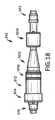
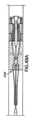
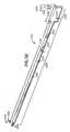
図27及び図28は、例示的な供給システム1210を示す。供給システム1210は、シース1212と、細長い部材1214と、先端1216とを含む。 27 and 28 illustrate an
シース1212は、第1端部1220と、第2端部1222と、長さ1223と、全長1223を通して延在し、且つ細長い部材1214の一部分、先端1216の一部分及び埋植可能な装置の一部分を受け入れるようにサイズ設定及び構成された管腔1226を画定する本体1224とを含む。シースの第2端部は、任意選択により、放射線不透過性材料を含み得る。細長い部材1214は、長手方向軸1229と、第1端部1230と、第2端部1232と、外側表面1236、内側表面1238、管腔1240及び切欠き1242を画定する本体1234とを有する。図示の実施形態において、細長い部材1214は、304ステンレス鋼から形成されている。管腔1240は、細長い部材1214の全長を通して延在し、且つワイヤガイドの一部分又は別の医療装置を受け入れるようにサイズ設定(例えば、0.035’’)及び構成されている。切欠き1242は、外側表面1236から内側表面1238まで細長い部材1214の本体1234内に長手方向軸1229に向かって且つ角度1243において細長い部材1214の第2端部1232に向かって延在する。図示の実施形態において、角度1243は、細長い部材1214の長手方向軸1229に対してゼロ度超である。切欠きは、細長い部材の長手方向軸に対して15度、30度、45度、60度又は75度に等しい、それ未満、それ超又はほぼそれに等しい角度などの任意の適切な角度で画定することができる。切欠き1242は、更に本明細書において詳述されているように、ローディングプラーの一部分を受け入れ且つそれと結合するようにサイズ設定及び構成されている。図示の実施形態において、角度1243は、細長い部材1214の長手方向軸1229に対して約45度に等しい。細長い部材1214は、内側表面1238及び管腔1240を画定するものとして示されているが、代替実施形態は、管腔を画定する内側表面を含まない、材料の中実片を有する細長い部材を含み得る。この代替実施形態では、細長い部材1214に関して上述したように、切欠きは、細長い部材として本体内で画定することができる。
先端1216は、細長い部材1214の第2端部1232上に配設され、且つ第1端部1246と、第2端部1248と、管腔1251、第1部分1252、第2部分1254及び第3部分1256を画定する本体1250とを有する。先端1216は、シース1212内に部分的に配設され、且つ埋植可能な医療装置が治療のポイントに供給され得るように、その上部において埋植可能な医療装置を受け入れるようにサイズ設定及び構成されている。図示の実施形態において、第1部分1252は、シース1212内に配設されるようにサイズ設定及び構成されている。一代替実施形態において、細長い部材は、先端が細長い部材の長さの一部分上に配設されるように、先端によって画定された管腔を通して配設することができる。切欠き1242は、ローディングプラーが切欠き内に配設され得ると共に、切欠き1242と先端1216との間に配設された又は先端1216上に配設された埋植可能な医療装置に解放可能に装着され得るように、先端1216の第1端部1246から、ローディングプラーの長さより大きい距離1257に位置決めされている。先端1216は、管腔1251を画定するものとして示されているが、一代替実施形態は、管腔を省略した材料の中実片を含む先端を含むことができる。 The
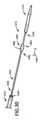
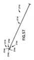
図29は、別の例示的な供給システム1310を示す。供給システム1310は、以下において詳述されている内容を除いて、図27及び図28に示され、且つ上述した供給システム1210に類似している。供給システム1310は、シース1312と、細長い部材1314と、先端1316と、把持部材1360とを含む。 FIG. 29 shows another
図示の実施形態において、細長い部材1314は、長手方向軸1329と、第1端部1330と、第2端部1332と、外側表面1336を画定する本体1334とを有する。把持部材1360は、細長い部材1314の第1端部1330と先端1316の第1端部1346との間で細長い部材1314に装着されている。把持部材1360は、第1端部1362と、第2端部1364と、長さ1365と、本体1366とを有する。使用時、把持部材1360は、シース1312によって画定された管腔1326内において、且つストレージ部材内に配設された埋植可能な医療装置によって画定された管腔内に配設されるようにサイズ設定及び構成されている。把持部材1360は、埋植可能な医療装置のフレームとシース1312との間に摩擦力を提供し、且つシース1312から解放される際、埋植可能な医療装置のジャンプが防止されるように、供給時の埋植可能な医療装置の制御された解放を支援している。バルーンが供給システム上に含まれる実施形態では、バルーンは、先端と把持部材との間に位置決めすることが可能であるか、又は先端とみなすことが可能であり、且つ把持部材の遠位に位置決めすることができる。これらの実施形態において、細長い部材は、バルーンチャンバと流体連通しており、且つシースの遠位に画定された膨張ポートまで延在する膨張管腔を画定することができる。 In the illustrated embodiment,
把持部材は、任意の適切な材料から形成することが可能であり、且つ任意の適切な構造的構成を有することが可能であり、且つ把持部材のための適切な材料及び構造的構成の選択は、その把持部材が含まれる供給システムの意図された使用法を含む様々な考慮事項に基づいたものであり得る。把持部材について適切であるとみなされる材料の例は、把持部材が装着される細長い部材を形成する材料の摩擦係数より大きい摩擦係数を有する任意の材料、ポリマー、シリコーン、ポリウレタン、ゴム及び特定の実施形態について適切であるとみなされる任意の他の材料を含む。 The gripping member can be formed from any suitable material and can have any suitable structural configuration, and the selection of suitable materials and structural configurations for the gripping member can be , may be based on a variety of considerations, including the intended use of the delivery system in which the gripping member is included. Examples of materials that are considered suitable for the gripping member include any material that has a coefficient of friction that is greater than the coefficient of friction of the material forming the elongated member to which the gripping member is attached, polymers, silicones, polyurethanes, rubbers, and certain implementations. Contains any other material deemed suitable for the form.
図30は、別の例示的な供給システム1410を示す。供給システム1410は、以下において詳述されている内容を除いて、図27及び図28に示され、且つ上述した供給システム1210に類似している。供給システム1410は、シース1412と、細長い部材1414と、先端1416と、把持部材1460とを含む。 FIG. 30 shows another
図示の実施形態において、供給システムは、切欠き1442と先端1416の第1端部1446との間で細長い部材1414に装着された把持部材1460を含む。把持部材1460は、第1端部1462と、第2端部1464と、長さ1465と、本体1466とを有する。使用時、把持部材1460は、シース1412によって画定された管腔1426内において、且つストレージ部材内に配設された埋植可能な医療装置によって画定された管腔内において配設されるようにサイズ設定及び構成されている。図示の例において、把持部材1460は、切欠き1442から、供給システム1410と共に使用されることを意図されたローディングプラーの長さ(例えば、長さ661、長さ2761)より大きい距離に位置決めされている。任意選択により、供給システムは、シース内において、且つ埋植可能な医療装置の供給を支援するために使用され得る細長い部材上において配設された内側プッシャカテーテルを含むことができる。加えて、供給システムは、切欠きと細長い部材の近端との間に配設された1つ又は複数のカーフを含むことができる。 In the illustrated embodiment, the delivery system includes a gripping
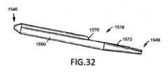
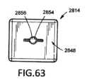
図31及び図32は、例示的な供給システムの細長い部材の第2端部に配設され得る代替的な先端1516を示す。先端1516は、以下において詳述されている内容を除いて、図27に示され、且つ上述した先端1216に類似している。 31 and 32 illustrate an
図示の実施形態において、先端1516の本体1550は、ショルダ1570及び平坦な表面1572を画定する。ショルダ1570は、先端1516の第1端部1546と先端1516の第2端部1548との間に配設されている。平坦な表面1572は、ショルダ1570から第2端部1548に向かって、ショルダ1570と第2端部1548との間の場所まで延在する。ショルダ1570及び平坦な表面1572の包含は、本明細書において記述されているものなどの別のコンポーネント(例えば、ローディング部材、ストレージ部材、装置ガード、装置ガードの平坦な表面)に対して先端1516及び装着された細長い部材を方向付けするためのメカニズムを提供する。 In the illustrated embodiment, the
図32A及び図32Bは、例示的な供給システムの細長い部材の第2端部に配設され得る代替的な先端1516’を示す。先端1516’は、以下において詳述されている内容を除いて、図27に示され、且つ上述した先端1216に類似している。 32A and 32B illustrate an alternative tip 1516' that may be disposed on the second end of the elongated member of an exemplary delivery system. Tip 1516' is similar to
図示の実施形態において、先端1516’の本体1550’は、第1凹部1570’及び第2凹部1572’を画定する。第1凹部1570’及び第2凹部1572’のそれぞれは、第1端部1546’から第2端部1548’に向かって延在し、且つ先端1516’及び装着された細長い部材が、本明細書において記述されているものなどの別のコンポーネント(例えば、ローディング部材、ストレージ部材、装置ガード、装置ガードの平坦な表面)に対して方向付けされ得るように、装置ガード又はキャップの一部分を受け入れるようにサイズ設定及び構成されている。図示の実施形態において、第1凹部1570’及び第2凹部1572’のそれぞれは、先端1516’の長手方向軸を通して延在する平面上に配設されている。但し、代替実施形態は、先端の長手方向軸を通して延在する第1平面上に配設された第1凹部と、第1平面に対して任意の適切な角度(例えば、45度)において先端の長手方向軸を通して延在する第2平面上に配設された第2凹部とを含むことができる。 In the illustrated embodiment, the body 1550' of the tip 1516' defines a first recess 1570' and a second recess 1572'. Each of the first recess 1570' and the second recess 1572' extends from the first end 1546' toward the second end 1548', and the tip 1516' and the attached elongated member are to receive a portion of the device guard or cap so that it can be oriented against another component (e.g., a loading member, a storage member, a device guard, a flat surface of the device guard) such as those described in Sized and configured. In the illustrated embodiment, each of the first recess 1570' and the second recess 1572' are disposed on a plane extending through the longitudinal axis of the tip 1516'. However, alternative embodiments include a first recess disposed on a first plane extending through the longitudinal axis of the tip, and a first recess disposed on a first plane extending through the longitudinal axis of the tip, and a first recess disposed on a first plane extending through the longitudinal axis of the tip; a second recess disposed on a second plane extending through the longitudinal axis.
第1凹部1570’及び第2凹部1572’が示されているが、先端の本体は、ストレージ装置及び/又はローディング装置の一部分に対する先端の方向付けを支援するために、任意の適切な数の凹部を画定することが可能であり、且つ画定する先端の本体のための凹部の適切な数の選択は、先端を形成している材料のタイプなどの様々な考慮事項に基づいたものであり得る。画定する先端の本体のための凹部の適切な数の例は、1つ、2つ、複数、3つ、4つ、5つ、5つ超並びに特定の実施形態について適切であるとみなされる任意の他の数を含む。 Although first recess 1570' and second recess 1572' are shown, the body of the tip may include any suitable number of recesses to assist in orienting the tip relative to a portion of the storage device and/or loading device. Selection of the appropriate number of recesses for the body of the tip capable of defining and defining the tip may be based on various considerations, such as the type of material forming the tip. Examples of suitable numbers of recesses for the body of the defining tip include one, two, multiple, three, four, five, more than five, as well as any deemed appropriate for a particular embodiment. Contains other numbers.
図32C及び図32Dは、例示的なストレージ装置のストレージ部材又は例示的なローディング装置のローディング部材に解放可能に装着され得る代替的な第1キャップ114’を示す。第1キャップ114’は、以下において詳述されている内容を除いて、図4及び図5に示され、且つ上述した第1キャップ114に類似している。 32C and 32D illustrate an alternative first cap 114' that may be releasably attached to a storage member of an exemplary storage device or a loading member of an exemplary loading device. The first cap 114' is similar to the
図示の実施形態において、第1キャップ114’は、ストレージ部材又はローディング部材の第1端部に解放可能に装着され得る装置ガード146’を含む。装置ガード146’は、長手方向軸147’と、第1端部148’と、第2端部150’と、ベース154’、第1突起156’、凹部160’、第1突起161’及び第2突起163’を画定する本体152’とを有する。ベース154’は、第1端部148’から第2端部150’に向かって延在し、且つストレージ部材のパセッジウェイ内に解放可能に装着されるようにサイズ設定及び構成されている。図示の実施形態において、ベース154’は、外径155’と、第1側部162’と、第2側部164’とを有し、且つ装置ガード146’とストレージ部材との間でスナップフィット装着を使用することにより、パセッジウェイ内でストレージ部材に解放可能に装着されるようにサイズ設定及び構成されている。 In the illustrated embodiment, the first cap 114' includes a device guard 146' that may be releasably attached to the first end of the storage or loading member. The device guard 146' has a longitudinal axis 147', a first end 148', a second end 150', a base 154', a first protrusion 156', a recess 160', a first protrusion 161' and a
第1突起156’は、第2側部164’から第2端部150’まで延在する。第1突起156’は、ベース154’と第2端部150’との間でテーパー化される外径157’を有する。凹部160’は、第1端部148’から第2端部150’に向かって凹部ベース166’まで延在し、且つ本明細書において更に詳述されているように、供給システムの一部分(例えば、先端1516’)を受け入れるようにサイズ設定及び構成されている。凹部160’は、第1部分168’と、第2部分170’とを有する。第1部分168’は、第1端部148’から第2部分170’まで一定である内径167’を有する。第2部分170’は、第1部分168’から凹部ベース166’までテーパー化される内径169’を有する。第1部分168’は、円筒形の構成を有し、且つ第2部分170’は、円錐形の構成を有する。第1突起161’及び第2突起163’のそれぞれは、凹部160’内に延在し、且つ突起161’、163’が、供給システムの先端によって画定された凹部内に配設された際、供給システムが装置ガード146’に対して回転的に固定されるように、先端と結合するように、且つ先端によって画定された凹部(例えば、凹部1570’、凹部1572’)内に配設されるようにサイズ設定及び構成されている。 The first protrusion 156' extends from the second side 164' to the second end 150'. The first projection 156' has an outer diameter 157' that tapers between the base 154' and the second end 150'. The recess 160' extends from the first end 148' toward the second end 150' to the recess base 166', and as further detailed herein, includes a portion of a dispensing system (e.g. , tip 1516'). The recess 160' has a first portion 168' and a second portion 170'. The first portion 168' has an inner diameter 167' that is constant from the first end 148' to the second portion 170'. The second portion 170' has an inner diameter 169' that tapers from the first portion 168' to the recessed base 166'. The first portion 168' has a cylindrical configuration and the second portion 170' has a conical configuration. Each of the first protrusion 161' and the second protrusion 163' extends within the recess 160', and when the protrusions 161', 163' are disposed within the recess defined by the distal end of the delivery system; The delivery system is disposed to mate with the tip and within a recess defined by the tip (e.g., recess 1570', recess 1572') such that the delivery system is rotationally fixed relative to
第1突起161’及び第2突起163’が示されているが、装置ガードの本体は、ストレージ装置及び/又はローディング装置の一部分に対する先端の方向付けを支援するために任意の適切な数の突起を画定することが可能であり、且つ画定する装置ガードの本体のための突起の適切な数の選択は、先端を形成している材料のタイプなどの様々な考慮事項に基づいたものであり得る。画定する装置ガードの本体のための突起の適切な数の例は、1つ、2つ、複数、3つ、4つ、5つ、5つ超及び特定の実施形態について適切であるとみなされる任意の他の数を含む。 Although a first protrusion 161' and a second protrusion 163' are shown, the body of the device guard may include any suitable number of protrusions to assist in orienting the tip relative to a portion of the storage device and/or loading device. The selection of the appropriate number of protrusions for the body of the device guard that is capable of defining and defining the tip may be based on various considerations such as the type of material forming the tip. . Examples of suitable numbers of protrusions for the body of the device guard defining are one, two, multiple, three, four, five, more than five and as deemed appropriate for the particular embodiment. Including any other number.
図33、図34、図35及び図36は、例示的なガイドシステム1610を示す。ガイドシステム1610は、ガイドボード1612と、ローディング部材1614と、ガイド部材1616とを含む。ローディング部材1614は、以下において詳述されている内容を除いて、図17に示され、且つ上述したローディング部材712に類似している。ガイドシステム1610は、ストレージ装置10、ストレージ装置110、ストレージ装置210、ストレージ装置310及び/又はストレージ装置510などの本明細書において記述されている任意の適切なストレージ装置と共に使用することができる。 33, 34, 35, and 36 illustrate an
ガイドボード1612は、第1端部1620と、第2端部1622と、第1側部1624と、第2側部1626と、上部表面1628と、下部表面1630と、切欠き1634及び複数のアパーチャ1636を画定する本体1632とを有する。切欠き1634は、第1端部1620から第2端部1622まで延在し、且つ本明細書において記述されているように、ローディング部材1614、ガイド部材1616及びストレージ部材又は装着された装置ガードを含むストレージ部材を受け入れるようにサイズ設定及び構成されている。複数のアパーチャ1636のアパーチャの第1の組1638は、第1端部1620の近傍に配設され、且つ複数のアパーチャ1636のアパーチャの第2の組1640は、アパーチャの第1の組1638と第2端部1622との間に配設されている。 The
図示の実施形態において、ローディング部材1614は、切欠き1634内に配設され、且つ取付ピン(図示されてはいない)を使用してガイドボード1612に解放可能に装着可能である。ローディング部材1614は、取付ピンを使用して第2部分1617に解放可能に装着された第1部分1615を有する。代わりに、ローディング部材の第1部分及び第2部分は、相互の関係において位置決めすることも可能であり、且つ相互に解放可能に装着されないことも可能である。ローディング部材1614は、長手方向軸1644と、第1端部1646と、第2端部1648と、第1開口部1652、第2開口部1654、パセッジウェイ1656、第1トラック1658、第2トラック1660、第3トラック1662、第4トラック1677、複数の取付パセッジウェイ1663及びガイドピン1665を画定する本体1650とを有する。第1開口部1652、第2開口部1654、パセッジウェイ1656、第1トラック1658、第2トラック1660及び複数の取付パセッジウェイ1663のそれぞれは、第1及び第2部分1615、1617によって協働して画定されている。パセッジウェイ1656は、第1開口部1652から第2開口部1654まで延在し、且つ第1部分1664と、第2部分1666と、第3部分1668と、第4部分1670と、第5部分1672とを有する。パセッジウェイ1656は、本明細書において記述されているものなどの埋植可能な医療装置、ローディングプラー及び供給システムの一部分を受け入れるようにサイズ設定及び構成されている。第1部分1664は、第1端部1646から第2部分まで延在し、且つ一定の内径を有する。但し、代替実施形態は、第1部分(例えば、第1部分1664)の包含を省略し得るであろう。第2部分1666は、第1部分1664から第3部分1668まで延在し、且つ第1部分1664から第3部分1668までテーパー化される内径1667を有する。第3部分1668は、第2部分1666から第5部分1672まで延在し、且つ第1端部1646において第1部分1664の内径1667より小さい内径1669を有する。第3部分1668は、埋植可能な医療装置の一部分、ローディングプラー及び供給システムの一部分(例えば、把持部材)を受け入れるようにサイズ設定及び構成されている。第4部分1670は、第3部分1668から第2端部1648まで延在し、且つ第3部分1668の内径1669より大きい幅1671を有する。第4部分1670は、本明細書において更に詳述されているように、開放又は部分的開放構成においてローディングプラーの一部分を受け入れるようにサイズ設定及び構成されている。第5部分1672は、第3部分1668(例えば、第2端部1648と第3部分1668との間の場所)から第2端部1648まで延在し、且つ第4部分1670の幅1671より小さく、且つ第3部分1668の内径1669より大きい内径1673を有する。第5部分1672は、本明細書において更に詳述されているように、供給システムのシースの一部分を受け入れるようにサイズ設定及び構成されている。第5部分1672と第3部分1668との間の直径の減少は、パセッジウェイ1656を通した供給システムのシースの前進に対する機械的ストップとして機能するショルダ1674を生成している。図示の実施形態において、第3部分1668は、長手方向軸1644に直交する平面に沿って取得された第1断面構成(例えば、円形断面構成)を有し、第4部分1670は、第3部分1668(例えば、第2端部1648と第2部分1666との間の場所)から第2端部1648まで延在し、且つ長手方向軸1644に直交する平面に沿って取得された第2断面構成(例えば、細長い断面構成、矩形の断面構成)を有し、且つ第5部分1672は、長手方向軸1644に直交する平面に沿って取得された第3断面構成(例えば、円形断面構成)を有する。図示の実施形態において、第1及び第3断面構成は、同一であり、且つ円形であり、及び第2断面構成は、第1及び第3断面構成と異なっており、且つ細長い。 In the illustrated embodiment,
使用時、ローディングプラーがパセッジウェイ1656を通して引っ張られた際、ローディングプラーは、パセッジウェイ1656の第2部分1666を通して移動するのに伴って圧縮され、且つ次いでパセッジウェイ1656の第4部分1670に到達した際に膨張する。 In use, when the loading puller is pulled through the
第1トラック1658及び第3トラック1662のそれぞれは、ローディング部材の長手方向軸1644を含む平面上に配設され、本体1650内にベース1651まで延在し、且つ第1端部1646から第4部分1670まで延在する。但し、代替実施形態は、第1及び第2トラックのそれぞれが、ローディング部材の長手方向軸を含まないか又はそれと接触しない平面上に配設されるように、又は第1及び第2トラックの1つのみがローディング部材の長手方向軸を含むか又はそれと接触する平面上に配設されるように、第1トラック及び第2トラックを画定することができる。第1トラック1658及び第3トラック1662のそれぞれは、ローディング部材1614の第1及び第2部分1615、1617が相互に装着された際、長手方向軸1644に直交する場所上において計測される厚さを有する。パセッジウェイ1656の第1部分1664に沿った第1トラック1658のベース1651と第3トラック1662のベース1651との間の距離は、第1部分1664の内径より大きい。パセッジウェイ1656の第2部分1666に沿った第1トラック1658のベース1651と第3トラック1662のベース1651との間の距離は、第2部分1666の内径1667より大きい。パセッジウェイ1656の第3部分1668に沿った第1トラック1658のベース1651と第3トラック1662のベース1651との間の距離は、第3部分1668の内径1669より大きく、且つ第4部分1670の幅1674より小さい。第2トラック1660及び第4トラック1677のそれぞれは、第1端部1646から第5部分1672まで延在する。代替実施形態において、第2トラック及び第4トラックは、ローディング部材から省略することができる。第1トラック1658及び第3トラック1662のそれぞれは、ローディングプラーの一部分を受け入れるようにサイズ設定及び構成され、且つ使用時にローディング部材1614を通してローディングプラーをガイドするためのメカニズムを提供する。第2トラック1660及び第4トラック1677のそれぞれは、埋植可能な医療装置の一部分を受け入れるようにサイズ設定及び構成されている。例えば、埋植可能な医療装置が、フレームの長手方向軸から外向きに延在する部分(例えば、1つ又は複数のマーカー、1つ又は複数のバーブ)を有するフレームを含む実施形態において、第2トラック及び第4トラックの1つ又はそれぞれは、使用時にローディング部材1614を通して埋植可能な医療装置をガイドするためのメカニズムを提供する。 Each of the
複数の取付パセッジウェイ1663のそれぞれのパセッジウェイは、1つ又は複数のアライメントピン(図示されてはいない)が、ガイドボード1612に対してローディング部材1614の位置を維持するために、パセッジウェイ及びアパーチャ内に位置決めされ得るように、ガイドボード1612のアパーチャの第2の組1640とアライメントするようにサイズ設定及び構成されている。ガイドピン1665のそれぞれは、ローディング部材1614の第1部分1615の第1端部1646から、第2端部1648から離れるように延在し、且つストレージ部材とローディング部材1614との間のアライメントを実現するために、ストレージ部材によって画定されたパセッジウェイ(例えば、パセッジウェイ280、パセッジウェイ282)によって受け入れられるようにサイズ設定及び構成されている。 Each of the plurality of
ガイド部材1616は、切欠き1634内に配設され、且つ取付ピン(図示されてはいない)を使用してガイドボード1612に解放可能に装着可能である。ガイド部材1616は、取付ピンを使用して第2部分1621に解放可能に装着された第1部分1619を有する。ガイド部材1616は、長手方向軸1675と、第1端部1676と、第2端部1678と、第1開口部1682、第2開口部1684、パセッジウェイ1686及び複数の取付パセッジウェイ1688を画定する本体1680とを有する。第1開口部1682、第2開口部1684、パセッジウェイ1686及び複数の取付パセッジウェイ1688のそれぞれは、第1及び第2部分1619、1621によって協働して画定されている。パセッジウェイ1686は、第1開口部1682から第2開口部1684まで延在し、且つ本明細書において記述されているものなど、供給システムの一部分(例えば、シース)を受け入れるようにサイズ設定及び構成されている。ガイド部材1616は、本明細書において更に詳述されているように、埋植可能な医療装置をローディングしつつ、供給システムの位置を維持するためのメカニズムを提供する。複数の取付パセッジウェイ1688のそれぞれのパセッジウェイは、1つ又は複数の取付ピン(図示されてはいない)が、ガイドボード1612に対してガイド部材1616の位置を維持するために、パセッジウェイ及びアパーチャ内に位置決めされ得るように、ガイドボード1612のアパーチャの第1の組1638とアライメントするようにサイズ設定及び構成されている。ガイドボード1612、ローディング部材1614及びガイド部材1616が別個の要素として示されているが、ガイドボードは、ローディング部材及び/又はガイド部材を有する統合されたコンポーネントであり得る。例えば、ガイド部材は、ガイドボードに永久的に装着することができる。
図37は、一実施形態によるストレージ装置1712と、一実施形態による装置ガード1714と、一実施形態による供給システム1716と、一実施形態によるガイドシステム1718と、使用のための命令1720と、ストレージ容器1722とを含む例示的なキット1710を示す。 FIG. 37 shows a
任意の適切なストレージ装置、装置ガード、供給システム、ローディング部材、ローディングアシスタ、ローディングプラー及びガイドシステムをキット内に含めることが可能であり、且つキット内に含まれる適切なストレージ装置、装置ガード、供給システム、ローディング部材、ローディングアシスタ、ローディングプラー及びガイドシステムの選択は、キットを使用して埋植されることを意図されている埋植可能な医療装置のタイプを含む様々な考慮事項に基づいたものであり得る。キット内に含むために適切であるとみなされるストレージ装置の例は、ストレージ装置10、ストレージ装置110、ストレージ装置210、ストレージ装置310、ストレージ装置510、本明細書において記述されているストレージ装置の変形形態及び一実施形態による任意の他のストレージ装置を含む。キットに含むために適切であるとみなされる装置ガードの例は、装置ガード146、装置ガード715、装置ガード1714、装置ガード2615、本明細書において記述されている装置ガードの変形形態及び一実施形態による任意の他の装置ガードを含む。キットに含むために適切であるとみなされる供給システムの例は、供給システム1210、供給システム1310、供給システム1410、供給システム2510、本明細書において記述されている供給システムの変形形態及び一実施形態による任意の他の供給システムを含む。キットに含むために適切であるとみなされるローディング部材の例は、ローディング部材712、ローディング部材1012、ローディング部材1614、ローディング部材2814、本明細書において記述されているローディング部材の変形形態及び一実施形態による任意の他のローディング部材を含む。キットに含むために適切であるとみなされるローディングアシスタの例は、ローディングアシスタ2710及び特定の実施形態について適切であるとみなされる任意の他のローディングアシスタを含む。キットに含むために適切であるとみなされるローディングプラーの例は、ローディングプラー652、ローディングプラー2752及び特定の実施形態について適切であるとみなされる任意の他のローディングプラーを含む。キット内に含むために適切であるとみなされるガイドシステムの例は、ガイドシステム1610、本明細書において記述されているガイドシステムの変形形態及び一実施形態による任意の他のガイドシステムを含む。図示の実施形態において、キット1710は、図15、図16及び図16Aに示されているストレージ装置510、図30に示されている供給システム1410並びに図33、図34、図35及び図36に示されているガイドシステム1610を含む。 Any suitable storage device, device guard, supply system, loading member, loading assister, loading puller and guide system can be included in the kit and any suitable storage device, device guard, supply system, loading member, loading assister, loading puller and guide system included in the kit. The selection of the system, loading member, loading assister, loading puller, and guide system is based on various considerations, including the type of implantable medical device that is intended to be implanted using the kit. It can be. Examples of storage devices that are considered suitable for inclusion in the kit include
図示の実施形態において、装置ガード1714は、以下において詳述されている内容を除いて、図17に示され、且つ上述した装置ガード715に類似している。装置ガード1714は、ストレージ部材512の第1端部520に解放可能に装着可能であり、且つ装置ガード1714の本体1760は、ベース1762と、側壁1764と、突起1766と、第1開口部1768と、第2開口部1770と、パセッジウェイ1772とを画定する。ベース1762及び側壁1764は、ストレージ部材512の一部分を受け入れるようにサイズ設定及び構成された空洞1770を協働して画定する。突起1766は、ベース1762から空洞1770を通して、空洞1770の外部である環境まで延在する。パセッジウェイ1772は、第1開口部1768から第2開口部1770まで延在し、且つ本明細書において詳述されているように、供給システムの一部分を受け入れるようにサイズ設定及び構成されている。 In the illustrated embodiment,
キット1710は、単一のストレージ装置510、単一の装置ガード1714、単一の供給システム1310及び単一のガイドシステム1610を含むものとして示されているが、本明細書において記述されているものなど、任意の適切な数及びタイプのストレージ装置、装置ガード、供給システム、ローディング部材、ローディングプラー、ローディングアシスタ及び/又はガイドシステムをキット内に含めることができる。特定の一実施形態に従ってキットに含まれるストレージ装置、装置ガード、供給システム、ローディング部材、ローディングプラー、ローディングアシスタ及び/又はガイドシステムの適切な数の選択は、キットを使用して埋植されることを意図されている埋植可能な医療装置のタイプなどの様々な考慮事項に基づいたものであり得る。キット内に含まれるストレージ装置、装置ガード、供給システム、ローディング部材、ローディングプラー、ローディングアシスタ及び/又はガイドシステムの適切な数の例は、少なくとも1つ、1つ、2つ、複数、3つ、4つ及び特定の実施形態について適切であるとみなされる任意の他の数を含む。
キット1710は、ストレージ装置1712、装置ガード1714、供給システム1716、ガイドシステム1718、使用のための命令1720及びストレージ容器1720のみを含むものとして示されているが、キットは、任意の適切な数の任意選択のコンポーネントを含むことができる。(例えば、ストレージ装置内に配設された、ストレージ装置を伴うことなしに提供された、ローディングプラーに事前に装着された、ローディングプラーに事前に装着され、且つ容器内に配設された、ローディングプラーに事前に装着され、且つローディング部材内に配設された)埋植可能な医療装置など、キット内に含むために適切であるとみなされる任意選択のコンポーネントの数の例は、1つ、少なくとも1つ、2つ、複数、3つ、4つ、5つ、5つ超及び特定の実施形態について適切であるとみなされる任意の他の数を含む。キット内に含むために適切であるとみなされる任意選択のコンポーネント及び/又は装置の例は、生理食塩水、潤滑剤、すすぎ落し溶液又は洗浄溶液によって充填された容器又はバッグ(例えば、I.V.バッグ)、チューブ、ボール、ガイドワイヤ、カテーテル、注射器及び/又は特定の実施形態について適切であるとみなされる任意の他のコンポーネント及び/又は装置を含む。 Although the
キット内に含まれるストレージ容器は、任意の適切な構造的構成を有することが可能であり、及び任意の適切な材料から形成することが可能であり、且つストレージ容器を形成するために適切な構造的構成及び材料の選択は、キットに含まれるストレージ装置、装置ガード、供給システム、ローディング部材及び/又はガイドシステムの数を含む様々な考慮事項に基づいたものであり得る。ストレージ容器を形成するために適切であるとみなされる構造的構成の例は、ボックス、蓋を含むボックス、ボックスに装着された(例えば、回動可能に装着された)蓋を含むボックス、バッグ及び特定の実施形態について適切であるとみなされる任意の他の構造的構成を含む。ストレージ容器を形成するために適切であるとみなされる材料の例は、金属、プラスチック、ガラス、本明細書において記述されている材料の組合せ及び特定の実施形態について適切であるとみなされる任意の他の材料を含む。図示の実施形態において、ストレージ容器1722は、剛性プラスチックから形成されたボックス1723である。 The storage container included within the kit can have any suitable structural configuration and can be formed from any suitable material and structure suitable for forming the storage container. The selection of physical configuration and materials may be based on a variety of considerations, including the number of storage devices, device guards, feeding systems, loading members, and/or guide systems included in the kit. Examples of structural configurations that are considered suitable for forming storage containers are boxes, boxes with a lid, boxes with a lid attached (e.g. pivotably attached) to the box, bags and including any other structural configurations deemed appropriate for a particular embodiment. Examples of materials deemed suitable for forming the storage container include metal, plastic, glass, combinations of materials described herein and any others deemed suitable for the particular embodiment. Contains materials. In the illustrated embodiment,
図38は、一実施形態によるローディング装置1812と、一実施形態による装置ガード1814と、一実施形態による供給システム1816と、使用のための命令1818と、ストレージ容器1820とを含む例示的なキット1810を示す。 FIG. 38 shows an
任意の適切なローディング装置、装置ガード及び供給システムをキット内に含めることが可能であり、且つキット内に含まれる適切なローディング装置、装置ガード及び供給システムの選択は、キットを使用して埋植されることを意図されている埋植可能な医療装置のタイプを含む様々な考慮事項に基づいたものであり得る。キットに含むために適切であるとみなされるローディング装置の例は、ローディング装置710、ローディング装置810、本明細書において記述されているローディング装置の変形形態及び一実施形態による任意の他のローディング装置を含む。キット内に含むために適切であるとみなされる装置ガードの例は、装置ガード146、装置ガード715、装置ガード1714、装置ガード2615、本明細書において記述されている装置ガードの変形形態及び一実施形態による任意の他の装置ガードを含む。キット内に含むために適切であるとみなされる供給システムの例は、供給システム1210、供給システム1310、供給システム1410、供給システム2510、本明細書において記述されている供給システムの変形形態及び一実施形態による任意の他の供給システムを含む。図示の実施形態において、キット1810は、図18、図19、図20、図21、図22、図23、図24、図25及び図26に示されているローディング装置810と、図30に示されている供給システム1410とを含む。 Any suitable loading device, device guard, and delivery system can be included in the kit, and selection of the appropriate loading device, device guard, and delivery system included in the kit can be used to perform implantation using the kit. This may be based on a variety of considerations, including the type of implantable medical device that is intended to be implanted. Examples of loading devices that are considered suitable for inclusion in the kit include
キット1810は、単一のローディング装置1812、単一の装置ガード1814及び単一の供給システム1816を含むものとして示されているが、本明細書において記述されているものなど、任意の適切な数及びタイプのローディング装置、装置ガード及び/及び供給システムをキット内に含めることができる。特定の実施形態に従ってキット内に含まれるローディング装置、装置ガード及び/又は供給システムの適切な数の選択は、キットを使用して埋植されることを意図されている埋植可能な医療装置のタイプなどの様々な考慮事項に基づいたものであり得る。キットに含まれるローディング装置、装置ガード及び/又は供給システムの適切な数の例は、少なくとも1つ、1つ、2つ、複数、3つ、4つ及び特定の実施形態について適切であるとみなされる任意の他の数を含む。 Although the
キット1810は、ローディング装置1812、装置ガード1814、供給システム1816、使用のための命令1818及びストレージ容器1820のみを含むものとして示されているが、キットは、任意の適切な数の任意選択のコンポーネントを含むことができる。(例えば、ローディング装置内に配設された、ローディング装置を伴うことなしに提供された、ローディングプラーに事前に装着された、ローディングプラーに事前に装着され、且つ容器内に配設された、ローディングプラーに事前に装着され、且つローディング部材内に配設された)埋植可能な医療装置など、キット内に含むために適切であるとみなされる任意選択のコンポーネントの数の例は、1つ、少なくとも1つ、2つ、複数、3つ、4つ、5つ、5つ超及び特定の実施形態について適切であるとみなされる任意の他の数を含む。キット内に含むために適切であるとみなされる任意選択のコンポーネント及び/又は装置の例は、生理食塩水、潤滑剤、すすぎ落し溶液又は洗浄溶液よって充填された容器又はバッグ(例えば、I.V.バッグ)、チューブ、ボール、ガイドワイヤ、カテーテル、注射器及び/又は特定の実施形態について適切であるとみなされる任意の他のコンポーネント及び/又は装置を含む。 Although the
本明細書において記述されている実施形態のストレージ部材、キャップ、装置ガード、一方弁、二方弁、ディフューザ、ローディング部材、ローディングプラー、ローディングアシスタ、コネクタ、カテーテル、細長い部材、プッシュ部材、先端、ガイドボード、ガイド部材及び任意の他の装置、コンポーネント、要素又は特徴は、任意の適切な材料から且つ任意の適切な製造方法を使用することにより形成することができる。適切な材料及び製造方法の選択は、装置、コンポーネント、要素又は特徴の意図された使用法を含む様々な考慮事項に基づいたものであり得る。本明細書において記述されている実施形態のストレージ部材、キャップ、装置ガード、一方弁、二方弁、ディフューザ、ローディング部材、ローディングプラー、ローディングアシスタ、コネクタ、カテーテル、細長い部材、プッシュ部材、先端、ガイドボード、ガイド部材及び任意の他の装置、コンポーネント、要素又は特徴を形成するために適切であるとみなされる材料の例は、生体適合性材料、生体適合性を有し得る材料、金属、プラスチック、ポリマー、透明材料、不透明材料及び特定の実施形態について適切であるとみなされる任意の他の材料を含む。任意選択により、本明細書において記述されている実施形態のストレージ部材、キャップ、装置ガード、一方弁、二方弁、ディフューザ、ローディング部材、ローディングプラー、ローディングアシスタ、コネクタ、カテーテル、細長い部材、プッシュ部材、先端、ガイドボード、ガイド部材及び任意の他の装置、コンポーネント、要素又は特徴の任意のものは、それ自体と、その自体が装着される別の要素との間に配設されたガスケット(例えば、Oリング)を含むことができる。 Storage members, caps, device guards, one-way valves, two-way valves, diffusers, loading members, loading pullers, loading assisters, connectors, catheters, elongate members, push members, tips, guides of embodiments described herein. The board, guide member and any other devices, components, elements or features may be formed from any suitable material and by using any suitable manufacturing method. Selection of appropriate materials and manufacturing methods may be based on a variety of considerations, including the intended use of the device, component, element, or feature. Storage members, caps, device guards, one-way valves, two-way valves, diffusers, loading members, loading pullers, loading assisters, connectors, catheters, elongate members, push members, tips, guides of embodiments described herein. Examples of materials considered suitable for forming the board, guide members and any other devices, components, elements or features include biocompatible materials, materials that may be biocompatible, metals, plastics, Includes polymers, transparent materials, opaque materials, and any other materials deemed suitable for a particular embodiment. Optionally, storage members, caps, device guards, one-way valves, two-way valves, diffusers, loading members, loading pullers, loading assisters, connectors, catheters, elongate members, push members of embodiments described herein. , the tip, the guide board, the guide member and any other device, component, element or feature may include a gasket (e.g. , O-ring).
ストレージ部材、キャップ、装置ガード、一方弁、ディフューザ、ローディング部材、ローディングプラー、ローディングアシスタ、コネクタ、カテーテル、細長い部材、プッシュ部材、先端、ガイドボード、ガイド部材及び本明細書において記述されている別の要素間の任意の装着は、要素間の装着の任意の適切な技法又は方法を利用することができる。2つの要素間の装着の適切な技法又は方法の選択は、要素を形成している1つ又は複数の材料を含む様々な考慮事項に基づいたものであり得る。本明細書において記述されている2つの要素間の適切であるとみなされる装着の技法及び方法の例は、図示のもの、ねじ山による接続、スナップフィット装着の使用、1つ又は複数のコネクタの使用、1つ又は複数の結合スロット及び突起、要素間の穿孔可能なメンブレイン、解放可能な装着、永久的な装着及び特定の用途について適切であるとみなされる装着の任意の他の技法又は方法を含む。 Storage members, caps, device guards, one-way valves, diffusers, loading members, loading pullers, loading assisters, connectors, catheters, elongated members, push members, tips, guide boards, guide members and other described herein. Any attachment between elements may utilize any suitable technique or method of attachment between elements. Selection of an appropriate technique or method of attachment between two elements may be based on a variety of considerations, including the material or materials forming the elements. Examples of attachment techniques and methods considered suitable between two elements described herein include those shown, threaded connections, use of snap-fit attachments, the use of one or more connectors, etc. The use of one or more coupling slots and protrusions, perforable membranes between elements, releasable attachment, permanent attachment and any other technique or method of attachment deemed appropriate for the particular application. including.
本明細書では、埋植可能な医療装置を消毒し、埋植可能な医療装置を保存し、埋植可能な医療装置をすすぎ落し、且つ埋植可能な医療装置を供給システム上にローディングする様々な方法について記述されている。本明細書において記述されている方法は、一連の行為として図示及び記述されているが、いくつかの行為は、これらの方法に従って、図示及び/又は記述されている順序において、異なる順序において且つ/又は本明細書において記述されている他の行為と共に同時に発生し得ることから、方法は、行為の順序により限定されるものではないことを理解及び認識されたい。 Various methods for disinfecting an implantable medical device, storing an implantable medical device, rinsing an implantable medical device, and loading an implantable medical device onto a delivery system are described herein. A method is described. Although the methods described herein are illustrated and described as a series of acts, some acts may be performed in a different order and/or in the order shown and/or described in accordance with these methods. It should be understood and appreciated that the method is not limited by the order of the acts, as they may occur simultaneously or with other acts described herein.
図39は、埋植可能な医療装置を消毒する例示的な方法1900の概略図である。 FIG. 39 is a schematic diagram of an
ステップ1902は、埋植可能な医療装置をストレージ部材内に挿入するステップを含む。別のステップ1904は、第1キャップをストレージ部材に装着するステップを含む。別のステップ1906は、消毒材料をストレージ部材内に導入するステップを含む。別のステップ1908は、消毒材料がストレージ部材から除去されるように、保持材料をストレージ部材内に導入するステップを含む。別のステップ1910は、第2キャップをストレージ部材に装着するステップを含む。 Step 1902 includes inserting the implantable medical device into the storage member. Another step 1904 includes attaching the first cap to the storage member. Another step 1906 includes introducing disinfectant material into the storage member. Another
ステップ1902は、本明細書において記述されているものなどの任意の適切な埋植可能な医療装置を使用することにより実現することができる。図示の実施形態において、埋植可能な医療装置1900を消毒する例示的な方法は、弁装置を消毒する方法を含む。ステップ1902は、埋植可能な医療装置が、ストレージ部材によって画定されたパセッジウェイの一部分(例えば、第1部分、第2部分)内に配設される時点まで、ストレージ部材の長手方向軸に沿ってストレージ部材の端部(例えば、第1端部、第2端部)に向かう軸方向の力を埋植可能な医療装置に印加することにより実現することができる。方法1900を完了させるために、本明細書において記述されているストレージ部材などの任意の他のストレージ部材を使用することができる。ステップ1902前又はその後に完了され得る任意選択のステップは、ローディングプラーを埋植可能な医療装置に解放可能に装着するステップを含む。Step 1902 can be accomplished using any suitable implantable medical device, such as those described herein. In the illustrated embodiment, an exemplary method of disinfecting an implantable
ステップ1904は、本明細書において記述されているキャップなどの任意の適切なキャップを使用して実現することが可能であり、且つキャップは、ストレージ部材の第1又は第2端部に装着することができる。代わりに、ステップ1904は、ストレージ部材にローディング部材を装着するステップを含むことが可能であり、且つ本明細書において記述されているローディング部材などの任意の適切なローディング部材を使用して実現することができる。 Step 1904 can be accomplished using any suitable cap, such as those described herein, and the cap can be attached to the first or second end of the storage member. Can be done. Alternatively, step 1904 can include attaching a loading member to the storage member and may be accomplished using any suitable loading member, such as those described herein. Can be done.
ステップ1906は、(例えば、注射器を使用して)消毒材料をストレージ部材内に導入する任意の適切な方法又は技法を使用することにより、且つストレージ部材によって画定されたパセッジウェイ内(例えば、パセッジウェイの第2部分のみ内、パセッジウェイの第1部分のみ内、パセッジウェイの第1部分及び第2部分の両方内)で蓄積するように又はパセッジウェイを通過するように、消毒材料をストレージ部材の第1開口部又は第2開口部に通すことにより実現することができる。任意の適切な消毒材料をストレージ部材内に導入することが可能であり、且つ適切な消毒材料の選択は、ストレージ部材内に配設されている埋植可能な医療装置のタイプを含む様々な考慮事項に基づいたものであり得る。消毒材料の例は、グルタルアルデヒド、ホルムアルデヒド、アルコール及び特定の実施形態について適切であるとみなされる任意の他の消毒材料を含む。任意選択のステップは、ストレージ部材から消毒材料を除去するステップを含む。任意選択により、ステップ1906は、ステップ1904前に実現することができる。 Step 1906 includes introducing disinfectant material into the storage member (e.g., using a syringe) and within the passageway defined by the storage member (e.g., the first part of the passageway). Disinfectant material is placed in the first opening of the storage member or passed through the passageway so that the disinfectant material accumulates in only the first part of the passageway, only in the first part of the passageway, in both the first part and the second part of the passageway) or passes through the passageway. This can be achieved by passing it through the second opening. Any suitable disinfecting material can be introduced into the storage member, and the selection of a suitable disinfecting material depends on various considerations, including the type of implantable medical device being disposed within the storage member. It can be based on matters. Examples of disinfecting materials include glutaraldehyde, formaldehyde, alcohol, and any other disinfecting material deemed appropriate for the particular embodiment. An optional step includes removing disinfectant material from the storage member. Optionally, step 1906 can be implemented before step 1904.
ステップ1908は、(例えば、注射器を使用して)保持材料をストレージ部材内に導入する任意の適切な方法又は技法を使用することにより、且つストレージ部材によって画定されたパセッジウェイ内(例えば、パセッジウェイの第2部分のみ内、パセッジウェイの第1部分のみ内、パセッジウェイの第1部分及び第2部分の両方内)で蓄積するように又はパセッジウェイを通過し、且つストレージ部材内の任意の消毒材料を置換するように、保持材料をストレージ部材の第1開口部又は第2開口部に通すことにより実現することができる。任意の適切な保持材料をストレージ部材内に導入することが可能であり、且つ適切な保持材料の選択は、ストレージ部材内に配設されている埋植可能な医療装置のタイプを含む様々な考慮事項に基づいたものであり得る。保持材料の例は、グルタルアルデヒド、生理食塩水、ホルムアルでヒド、リン酸緩衝液、リン酸緩衝生理食塩水(PBS)、作用物質、生物学的作用物質、被覆、吸収可能な被覆、薬剤、クエンチング溶液、アミノ酸を含み得るクエンチング溶液、抗石灰化材料、すすぎ落し流体、洗浄流体及び特定の実施形態について適切であるとみなされる任意の他の保持材料を含む。任意選択により、ステップ1908は、複数回(例えば、2回、3回)にわたって完了させることができる。任意選択により、ステップ1908は、ステップ1904前且つステップ1906後に実現することができる。
ステップ1910は、本明細書において記述されているキャップなどの任意の適切なキャップを使用して実現することが可能であり、且つキャップは、キャップを含まないストレージ部材の第1又は第2端部に装着することができる。一代替実施形態において、ステップ1904は、ストレージ材料にキャップを装着するステップを含むことができ、且つステップ1910は、ローディング部材をストレージ部材に装着するステップを含むことができる。図40は、例示的なストレージ部材1914内に保存されている埋植可能な医療装置1912を示す。 Step 1910 can be accomplished using any suitable cap, such as the caps described herein, and the cap can be attached to the first or second end of the storage member that does not include a cap. It can be attached to. In an alternative embodiment, step 1904 can include attaching a cap to the storage material, and step 1910 can include attaching a loading member to the storage member. FIG. 40 shows an implantable
様々なステップ、代替的なステップ及び任意選択のステップを例示的な方法1900に関して上述したが、これらのステップ、代替的なステップ及び任意選択のステップは、例示的な方法2000、例示的な方法2100、例示的な方法2200、例示的な方法2300、例示的な方法2400及び/又は例示的な方法2900に関して本明細書において記述されている方法、ステップ、代替的なステップ及び/又は任意選択のステップ内に含めることが可能であり、それと同時に実現することが可能であり、且つ/又はその代替形態として実現することができる。 Although various steps, alternative steps, and optional steps are described above with respect to
図41は、埋植可能な医療装置を消毒する別の例示的な方法2000の概略図を示す。 FIG. 41 shows a schematic diagram of another
ステップ2002は、埋植可能な医療装置をストレージ部材内に挿入するステップを含む。別のステップ2004は、第1キャップをストレージ部材に装着するステップを含む。別のステップ2006は、第2キャップをストレージ部材に装着するステップを含む。別のステップ2008は、消毒材料をストレージ部材内に導入するステップを含む。別のステップ2010は、消毒材料がストレージ部材から除去されるように、保持材料をストレージ部材内に導入するステップを含む。
ステップ2002は、ステップ1902に関して上述したように実現することができる。
ステップ2004は、本明細書において記述されているキャップなど、任意の適切なキャップを使用して実現することが可能であり、且つキャップは、ストレージ部材の第1又は第2端部に装着することができる。代わりに、ステップ2004は、ローディング部材をストレージ部材に装着するステップを含むことが可能であり、且つ本明細書において記述されているローディング部材などの任意の適切なローディング部材を使用して実現することができる。
ステップ2006は、本明細書において記述されているキャップなどの任意の適切なキャップを使用して実現することが可能であり、且つキャップは、キャップを含まないストレージ部材の第1又は第2端部に装着することができる。
ステップ2008は、消毒材料がストレージ部材の第1開口部又は第2開口部を通過し、且つストレージ部材によって画定されたパセッジウェイ内(例えば、パセッジウェイの第2部分のみ内、パセッジウェイの第1部分のみ内、パセッジウェイの第1部分及び第2部分の両方内)で蓄積するように又はパセッジウェイを通過するように、消毒材料をストレージ部材内に導入する任意の適切な方法又は技法を使用して実現することができる。例えば、消毒材料を収容しているバッグに接続された注射器又はラインを第1一方弁に装着することが可能であり、且つ消毒材料がストレージ部材内に収容され、且つ第2一方弁を通過しないように、消毒流体をストレージ部材内に導入するために利用することができる。代わりに、第2一方弁を通して且つストレージ部材内に、又は第1一方弁、ストレージ部材及び第2一方弁を通して、又は第2一方弁、ストレージ部材及び第1一方弁を通して消毒流体を通過させるために、バッグに接続された注射器又はラインを使用することもできる。任意の適切な消毒材料を、本明細書において記述されているものなどのストレージ部材内に導入することができる。任意選択のステップは、一方弁から注射器又はラインを除去するステップを含む。
ステップ2010は、保持材料がストレージ部材の第1開口部又は第2開口部を通過し、且つストレージ部材によって画定されたパセッジウェイ内(例えば、パセッジウェイの第2部分のみ内、パセッジウェイの第1部分のみ内、パセッジウェイの第1部分及び第2部分の両方内)で蓄積されるように又はパセッジウェイを通過するように、保持材料をストレージ部材内に導入する任意の適切な方法又は技法を使用して実現することができる。例えば、保持材料を収容するバッグに接続された注射器又はラインを第1一方弁に装着することが可能であり、且つ保持材料がストレージ部材内に収容され、且つ第2一方弁を通過しないように、保持流体をストレージ部材内に導入するために利用することができる。代わりに、第2一方弁を通して且つストレージ部材内に、又は第1一方弁、ストレージ部材及び第2一方弁を通して、又は第2一方弁、ストレージ部材及び第1一方弁を通して保持流体を通すために、バッグに接続された注射器又はラインを使用することもできる。任意選択のステップは、注射器又はラインを一方弁から除去するステップを含む。本明細書において記述されているものなど、任意の適切な保持材料をストレージ部材内に導入することができる。任意選択により、ステップ2010は、複数回(例えば、2回、3回)にわたって完了させることができる。これは、ステップ2010が完了するたびに特定の期間(例えば、1分、5分)にわたって且つ/又は規定された保持流体の容積がストレージ部材を通過する時点まで完了させることができる。図42は、例示的なストレージ部材2014内に保存されている埋植可能な医療装置2012と、埋植可能な医療装置2012に予め装着された、第1及び第2屈曲部並びに第1及び第2屈曲部間の湾曲のみを画定するローディングプラー2016とを示す。
様々なステップ、代替的なステップ及び任意選択のステップを例示的な方法2000に関して上述したが、これらのステップ、代替的なステップ及び任意選択のステップは、例示的な方法1900、例示的な方法2100、例示的な方法2200、例示的な方法2300、例示的な方法2400及び/又は例示的な方法2900に関して本明細書において記述されている方法、ステップ、代替的なステップ及び又は任意選択のステップ内に含めることが可能であり、それと同時に実現することが可能であり、且つ/又はその代替形態として実現することができる。 Although various steps, alternative steps, and optional steps are described above with respect to
図43は、埋植可能な医療装置を保存する例示的な方法2100の概略図である。 FIG. 43 is a schematic diagram of an
ステップ2102は、消毒された埋植可能な医療装置をストレージ部材内に挿入するステップを含む。別のステップ2104は、第1キャップをストレージ部材に装着するステップを含む。別のステップ2106は、保持材料をストレージ部材内に導入するステップを含む。別のステップ2108は、第2キャップをストレージ部材に装着するステップを含む。
ステップ2102は、ステップ1902に関して上述したように実現することができる。ステップ2102前に完了され得る任意選択のステップは、埋植可能な医療装置を消毒するステップ、埋植可能な医療装置をすすぎ落しするステップ及び/又はローディングプラーを埋植可能な医療装置に装着するステップを含む。これらの任意選択のステップは、従来の消毒及び/又はすすぎ落し方法又は本明細書において記述されているものを使用して実現することができる。代替実施形態において、ステップ2102は、ストレージ部材内に配設された消毒済みの埋植可能な医療装置を取得するステップを含むことができる。
ステップ2104は、本明細書において記述されているキャップなどの任意の適切なキャップを使用して実現することが可能であり、且つキャップは、ストレージ部材の第1又は第2端部に装着することができる。代わりに、ステップ2104は、ローディング部材をストレージ部材に装着するステップを含むことが可能であり、且つ本明細書において記述されているローディング部材などの任意の適切なローディング部材を使用して実現することができる。
ステップ2106は、保持部材をストレージ部材内に導入する任意の適切な方法又は技法を使用して(例えば、注射器を使用して)、且つストレージ部材によって画定されたパセッジウェイ内(例えば、パセッジウェイの第2部分のみ内、パセッジウェイの第1部分のみ内、パセッジウェイの第1部分及び第2部分の両方内)で蓄積されるか又はパセッジウェイを通して通過するように、保持材料をストレージ部材の第1開口部又は第2開口部に通すことにより実現することができる。本明細書において記述されているものなどの任意の適切な保持材料をストレージ部材内に導入することができる。任意選択により、ステップ2106は、複数回(例えば、2回、3回)にわたって完了させることできる。任意選択により、ステップ2106は、ステップ2104前又はステップ2108後に実現することができる。ステップ2106がステップ2108に続いて実現される実施形態において、ステップ2106は、保持材料がストレージ部材の第1開口部又は第2開口部を通過し、且つストレージ部材によって画定されたパセッジウェイ内(例えば、パセッジウェイの第2部分のみ内、パセッジウェイの第1部分のみ内、パセッジウェイの第1部分及び第2部分の両方内)で蓄積するか又はパセッジウェイを通して通過するように、保持材料をストレージ部材内に導入する任意の適切な方法又は技法を使用して実現することができる。例えば、保持材料を収容する注射器を第1一方弁に装着することが可能であり、且つ保持材料がストレージ部材内に収容され、且つ第2一方弁を通過しないように、保持流体をストレージ部材内に導入するために利用することができる。代わりに、保持流体を、第2一方弁を通して且つストレージ部材内に、又は第1一方弁、ストレージ部材及び第2一方弁を通して、又は第2一方弁、ストレージ弁及び第1一方弁を通して通過させるために注射器を使用することができる。この実施形態において、ステップ2106は、複数回(例えば、2回、3回)にわたって完了させることができる。これは、ステップ2106が完了するたびに特定の期間(例えば、1分、5分)にわたって且つ/又は規定された保持流体の容積がストレージ部材を通過する時点まで完了させることができる。任意選択のステップは、一方弁から注射器又はラインを除去するステップを含む。
ステップ2108は、本明細書において記述されているキャップなど、任意の適切なキャップを使用して実現することが可能であり、且つキャップは、キャップを含まないストレージ部材の第1又は第2端部に装着することができる。
様々なステップ、代替的なステップ及び任意選択のステップについて例示的な方法2100に関して上述したが、これらのステップ、代替的なステップ及び任意選択のステップは、例示的な方法1900、例示的な方法2000、例示的な方法2200、例示的な方法2300、例示的な方法2400及び/又は例示的な方法2900に関して本明細書において記述されている方法、ステップ、代替的なステップ及び/又は任意選択のステップ内に含めることが可能であり、それと同時に実現することが可能であり、且つ/又はその代替形態として実現することができる。 Although various steps, alternative steps, and optional steps are described above with respect to
図44は、埋植可能な医療装置をすすぎ落しする例示的な方法2200の概略図である。 FIG. 44 is a schematic diagram of an
ステップ2202は、すすぎ落し材料を含む装置をストレージ装置の一方弁に装着するステップを含む。別のステップ2204は、ストレージ装置を通過するように、すすぎ落し材料をストレージ装置内に導入するステップを含む。別のステップ2206は、すすぎ落し材料をストレージ装置内に導入するステップを停止するステップを含む。
ステップ2202は、任意の適切な装着の方法又は技法を使用することにより、且つすすぎ落し材料を含むバッグに装着された注射器、ライン及び特定の実施形態について適切であるとみなされる任意の他の装置などのすすぎ落し材料を含む任意の適切な装置を使用することにより実現することができる。任意の適切なすすぎ落し材料を装置内に含めることが可能であり、且つ適切なすすぎ落し材料の選択は、ストレージ部材内に配設されている埋植可能な医療装置のタイプを含む様々な考慮事項に基づいたものであり得る。すすぎ落し材料の例は、生理食塩水、作用物質、生物学的作用物質、被覆、吸収可能な被覆、薬剤、リン酸緩衝液、リン酸緩衝生理食塩水(PBS)及び特定の実施形態について適切であるとみなされる任意の他のすすぎ落し材料を含む。記述されている実施形態において、装置は、ストレージ装置の第1一方弁に装着されている。但し、代替実施形態は、ストレージ装置の第2一方弁又は二方弁に装着された装置を含むことができる。
ステップ2202は、装置をストレージ装置に装着することによって完了されるものとして記述されているが、代替実施形態は、装置をローディング装置に装着するステップを含むことができる。ステップ2202は、装置をストレージ装置及び/若しくはローディング装置の第1一方弁、ストレージ装置及び/若しくはローディング装置の第1二方弁、ストレージ装置及び/若しくはローディング装置の第2一方弁又はストレージ装置及び/若しくはローディング装置の第2二方弁に装着することにより実現することができる。 Although
ステップ2204は、すすぎ落し材料がストレージ部材の第1開口部又は第2開口部を通過し、且つストレージ部材によって画定されたパセッジウェイ内(例えば、パセッジウェイの第2部分のみ内、パセッジウェイの第1部分のみ内、パセッジウェイの第1部分及び第2部分の両方内)で蓄積するか又はパセッジウェイを通過するように、すすぎ落し材料をストレージ装置に導入する任意の適切な方法又は技法を利用して実現することができる。代わりに、すすぎ落し流体を、第2一方弁を通して且つストレージ部材内に、又は第1一方弁、ストレージ部材及び第2一方弁を通して、又は第2一方弁、ストレージ部材及び第1一方弁を通して通過させるために注射器を使用することもできる。代わりに、すすぎ落し材料を収容する注射器を第1一方弁に装着することが可能であり、且つすすぎ落し材料がストレージ部材内に収容され、且つ第2一方弁を通過しないように、すすぎ落し流体をストレージ部材内に導入するために利用することもできる。ステップ2204は、複数回(例えば、2回、3回)にわたって完了させることができる。これは、ステップ2204が完了するたびに特定の期間(例えば、1分、5分)にわたって且つ/又は規定されたすすぎ落し流体の容積がストレージ部材を通過する時点まで完了させることができる。
任意選択により、ステップ2202、2204、2206は、ストレージ部材を当初通過したすすぎ落し流体と異なる第2のすすぎ落し流体を使用することにより、1回以上にわたって反復することができる。任意選択のステップは、ステップ2204において又はステップ2204の完了後にストレージ部材を揺動させるステップを含む。 Optionally,
方法2200は、一方弁を使用して実現されるものとして記述したが、他の実施形態は、1つの又は複数の一方弁の包含を省略したストレージ装置及び/又はローディング装置を含むことができる。これらの実施形態において、方法2200は、第1キャップ、第2キャップ、第1一方弁及び/又は第2一方弁を除去するステップ、すすぎ落し材料内でストレージ部材を浸漬するステップ、任意選択により、ストレージ部材を揺動させるステップ及びすすぎ落し材料からストレージ部材を除去するステップを含むことができる。本明細書において記述されている方法において、一方弁の任意の包含は、代替実施形態において、二方弁と置換することができる。 Although
様々なステップ、代替的なステップ及び任意選択のステップについて例示的な方法2200に関して上述したが、これらのステップ、代替的なステップ及び任意選択のステップは、例示的な方法1900、例示的な方法2000、例示的な方法2100、例示的な方法2300、例示的な方法2400及び/又は例示的な方法2900に関して本明細書において記述されている方法、ステップ、代替的なステップ及び/又は任意選択のステップ内に含めることが可能であり、それと同時に実現することが可能であり、且つ/又はその代替形態として実現することができる。 Although various steps, alternative steps, and optional steps are described above with respect to
図45は、埋植可能な医療装置を供給システム上にローディングする例示的な方法2300の概略図である。 FIG. 45 is a schematic diagram of an
ステップ2302は、埋植可能な医療装置を収容するストレージ部材から第1キャップを除去するステップを含む。別のステップ2304は、ストレージ部材からディフューザを除去するステップを含む。別のステップ2306は、装置ガードをストレージ部材に装着するステップを含む。別のステップ2308は、第2キャップをストレージ部材から除去するステップを含む。別のステップ2310は、ストレージ部材をガイドシステムのローディング部材に装着するステップを含む。別のステップ2312は、ストレージ部材、ローディング部材を通過し、且つ部分的に装置ガード内に配設されるように、供給システムの一部分にストレージ部材に向かう軸方向の力を印加するステップを含む。別のステップ2314は、供給システムの細長い部材によって画定された切欠き内にローディングプラーを位置決めするステップを含む。別のステップ2316は、ローディングプラーの第1及び第2端部がローディング部材の第4部分内に配設される時点まで、供給システムの細長い部材にストレージ部材から離れる方に向かう軸方向の力を印加するステップを含む。別のステップ2318は、供給システム及びローディング部材からローディングプラーを除去するステップを含む。別のステップ2320は、シースがローディング部材に接触する時点まで、細長い部材の位置を維持しつつ、供給システムのシースにローディング部材に向かう軸方向の力を印加するステップを含む。別のステップ2322は、細長い部材がローディング部材から後退し、且つ医療装置がシース内に前進するように、シースの位置を維持しつつ、細長い部材にストレージ部材から離れる方に向かう軸方向の力を印加するステップを含む。別のステップ2324は、ローディング部材から供給システムを除去するステップを含む。
ステップ2302は、キャップがストレージ部材から除去されるように、第1キャップにストレージ部材から離れる方に向かう力(例えば、軸方向の力、回転力)を印加することにより実現することができる。力のタイプは、キャップとストレージ部材との間の装着のタイプに依存することになる。
ステップ2304は、ディフューザがストレージ部材内に解放可能に配設されている実施形態では、ディフューザにストレージ部材から離れる方に向かう力を印加するなどによる任意の適切な方式により実現することができる。代わりに、ディフューザがキャップに永久的に装着されているか又は解放可能に装着されている実施形態では、ステップ2304は、ステップ2302と同時に実現することができる。
ステップ2306は、装置ガードがストレージ部材に装着される時点まで、装置ガードにストレージ部材に向かう力を印加することにより実現することができる。ステップ2306は、本明細書において記述されている装置ガードなどの任意の適切な装置ガードを使用して実現することができる。一代替実施形態において、ステップ2306は、埋植可能な医療装置を供給システム上にローディングする方法から省略することができる。
ステップ2308は、キャップがストレージ部材から除去されるように、第2キャップにストレージ部材から離れる方に向かう力(例えば、軸方向の力、回転力)を印加することにより実現することができる。力のタイプは、キャップとストレージ部材との間の装着のタイプに依存することになる。
ステップ2310は、ストレージ部材がローディング部材に装着される時点まで、ストレージ部材にローディング部材に向かう力を印加するか、ストレージ部材がローディング部材に装着される時点までローディング部材にストレージ部材に向かう力を印加するか、又はストレージ部材にローディング部材に向かう力を印加し、且つストレージ部材がローディング部材に装着される時点までローディング部材にストレージ部材に向かう力を印加することにより実現することができる。図46及び図46Aは、ガイドシステム2334のローディング部材2332に装着されたストレージ部材2330を示す。
ステップ2312は、本明細書において記述されている供給システムなど、任意の適切な供給システムを使用して実現することができる。ステップ2312は、シースの位置を維持し、且つ細長い部材がストレージ部材、ローディング部材を通過し、且つ装置ガード内に部分的(例えば、先端)に配設される時点まで、細長い部材にローディング部材に向かう軸方向の力を印加することにより実現することができる。
ステップ2314は、ローディングプラーが細長い部材によって画定された切欠き内に配設される時点まで、ローディングプラーに供給システムの細長い部材に向かう力を印加することにより実現することができる。図47及び図47Aは、装置ガード2338内に部分的に配設された供給システム2336と、細長い部材2344によって画定された切欠き2342内に配設されたローディングプラー2340とを示す。図48及び図48Aは、開放状態にある、埋植可能な医療装置から自由であり、且つローディング部材の第4部分内に配設されたローディングプラー2340を示す。本明細書において更に詳述されているように、ローディングプラー2752が利用されている実施形態では、別のステップは、第1及び第2部分のそれぞれに対して、当初はローディングプラー2752の長手方向軸2757に向けられ、そして第1及び第2部分が長手方向軸2757を通過したら、ローディングプラーを開放構成に移動させるために長手方向軸2757から離れる方に向けられる軸方向の力を印加するステップを含む。
ステップ2318は、供給システムから自由になる時点まで、ローディングプラーに供給システムから離れる方に向かう軸方向の力を印加することにより実現することができる。図49及び図49Aは、ローディング部材に接触するように、ローディングプラーに向かって前進したシースを示す(例えば、これは、ローディング部材によって画定されたパセッジウェイ内で画定されたショルダ1674と接触しており、これは、ローディング部材の第2端部に接触している)。
ステップ2322は、任意選択により、シースの位置が、細長い部材がシース内に後退している間に維持され得るように、使用時にローディング部材とシースとの間の解放可能な装着を提供する、ローディング部材に装着されているか又はそれとは別個の構造を使用することにより実現することができる。例えば、ローディング部材は、シースと結合し、且つそれをローディング部材から除去するために軸方向の力がシースに印加される時点までシースの位置を維持するようにサイズ設定及び構成された、ローディング部材によって画定されたパセッジウェイ内に延在するコレット又は曲がりやすいフラップを含むことができる。
ステップ2324は、供給システムがローディング部材から自由になる時点まで、供給システムにローディング部材から離れる方に向かう軸方向の力を印加することにより実現することができる。任意選択のステップは、患者の身体内に埋植可能な医療装置を埋植するステップを含む。別の任意選択のステップは、装置ガードを使用して埋植可能な医療装置に対して供給システムの先端を方向付けするステップを含む。
様々なステップ、代替的なステップ及び任意選択のステップについて例示的な方法2300に関して説明したが、これらのステップ、代替的なステップ及び任意選択のステップは、例示的な方法1900、例示的な方法2000、例示的な方法2100、例示的な方法2200、例示的な方法2400及び/又は例示的な方法2900に関して本明細書において記述されている方法、ステップ、代替的なステップ及び/又は任意選択のステップ内に含めることが可能であり、それと同時に実現することが可能であり、且つ/又はその代替形態として実現することできる。 Although various steps, alternative steps, and optional steps have been described with respect to
図50は、埋植可能な医療装置を供給システム上にローディングする別の例示的な方法2400の概略図である。 FIG. 50 is a schematic diagram of another
ステップ2402は、埋植可能な医療装置を収容するストレージ部材からキャップを除去するステップを含む。別のステップ2404は、ストレージ部材からディフューザを除去するステップを含む。別のステップ2406は、装置ガードをストレージ部材に装着するステップを含む。別のステップ2408は、細長い部材がストレージ部材を通過し、且つ装置ガード内に部分的に配設されるように、供給システムのシースの位置を維持しつつ、供給システムの細長い部材にストレージ部材に向かう軸方向の力を印加するステップを含む。別のステップ2410は、供給システムの細長い部材によって画定された切欠き内にローディングプラーを位置決めするステップを含む。別のステップ2412は、ローディングプラーの第1及び第2端部がローディング部材の第4部分内に配設される時点まで、供給システムの細長い部材にローディング部材から離れる方に向かう軸方向の力を印加するステップを含む。別のステップ2414は、供給システム及びローディング部材からローディングプラーを除去するステップを含む。別のステップ2416は、シースがローディング部材に接触する時点まで、細長い部材の位置を維持しつつ、供給システムのシースにローディング部材に向かう軸方向の力を印加するステップを含む。別のステップ2418は、細長い部材がローディング部材から後退し、且つ医療装置がシース内に前進するように、シースの位置を維持しつつ、細長い部材にローディング部材から離れる方に向かう軸方向の力を印加するステップを含む。別のステップ2420は、ローディング部材から供給システムを除去するステップを含む。
ステップ2404は、ステップ2304に関して上述したように実現することができる。ステップ2406は、本明細書において記述されている装置ガードなどの任意の適切な装置ガードを使用して実現することができる。一代替実施形態において、ステップ2406は、埋植可能な医療装置を供給システム上にローディングする方法から省略することができる。ステップ2408は、本明細書において記述されている供給システムなどの任意の適切な供給システムを使用して実現することができる。供給システム上に埋植可能な医療装置をローディングする方法で使用されているストレージ部材の構成に応じて、埋植可能な医療装置は、ローディングプロセスにおいて湿潤性を有することができる。図51及び図51Aは、装置ガード2424内に部分的に配設された供給システム2422と、細長い部材2430によって画定された切欠き2428内に配設されたローディングプラー2426とを示す。図52及び図52Aは、開放構成においてローディングプラー2426を示す。図53及び図53Aは、ローディング部材2434と接触するように、ローディング部材2434に向かって前進したシース2432を示す。供給システム内に配設された際、埋植可能な医療装置は、把持部材上において部分的に配設され得ると共に、先端の近傍において全体的に配設され得る。任意選択のステップは、埋植可能な医療装置を患者の身体内に埋植するステップを含む。別の任意選択のステップは、装置ガードを使用して埋植可能な医療装置に対して供給システムの先端を方向付けするステップを含む。別の任意選択のステップは、ローディングプラーを曝露するためにローディング部材から第2キャップを除去するステップを含む。
様々なステップ、代替的なステップ及び任意選択のステップについて例示的な方法2400に関して上述したが、これらのステップ、代替的なステップ及び任意選択のステップは、例示的な方法1900、例示的な方法2000、例示的な方法2100、例示的な方法2200、例示的な方法2300及び/又は例示的な方法2900に関して本明細書において記述されている方法、ステップ、代替的なステップ及び/又は任意選択のステップ内に含めることが可能であり、それと同時に実現することが可能であり、且つ/又はその代替形態として実現することができる。 Although various steps, alternative steps, and optional steps are described above with respect to
図54は、別の例示的な供給システム2510を示す。供給システム2510は、以下において詳述されている内容を除いて、図30に示され、且つ上述した供給システム1410に類似している。供給システム2510は、シース2512と、細長い部材2514と、先端2516と、把持部材2560と、プッシュ部材2570とを含む。 FIG. 54 shows another
図示の実施形態において、プッシュ部材2570は、シース2512によって画定された管腔2526内に部分的に配設され、且つ第1端部2572と、第2端部2574と、長さ2575と、長さ2575の全体を通して延在し、且つ細長い部材2514の一部分を受け入れるようにサイズ設定及び構成された、管腔2578を画定する本体2576とを有する。任意選択により、プッシュ部材を形成する材料は、視覚化の改善のために充填された放射線不透過体を含むことが可能であり、且つ/又はプッシュ部材は、把持部材及び/又は先端の一部分を受け入れるようにサイズ設定及び構成することができる。シース2512によって画定された管腔2526は、細長い部材2514の一部分、把持部材2560、細長い部材及び/又は把持部材上に配設された埋植可能な医療装置並びに先端2516の一部分を受け入れるようにサイズ設定及び構成されている。但し、代替実施形態は、先端の一部分を受け入れないようにサイズ設定及び構成された管腔を画定するシースを含むことができる。使用時、シース2512によって画定された管腔2526内に配設された埋植可能な医療装置を配備することが望ましい場合、ユーザーは、細長い部材2514及びプッシュ部材2570の位置を維持しつつ、先端2516から離れる方に向けられ且つ細長い部材2514の第1端部2530に向かう軸方向の力をシース2512に印加している。代わりに、ユーザーは、シース2512の位置を維持しつつ、細長い部材2514及びプッシュ部材2570にシースに向けられた軸方向の力を印加している。シース2512の第2端部2522が把持部材2560と切欠き2542との間のポイントに位置決めされたら、ユーザーは、プッシュ部材2570の位置を維持することが可能であり、且つ先端2516がシース2512の第2端部2522に向かって前進するように、細長い部材2514にシースから離れる方に向かう軸方向の力を印加することが可能であるか、又はプッシュ部材2570の第2端部2574が先端2516に向かって若しくは先端2516の第2端部2548を越えて前進するように、細長い部材2514の位置を維持しつつ、プッシュ部材2570に先端に向かう軸方向の力を印加することができる。これは、埋植可能な医療装置を治療のポイントにおいて供給するためのメカニズムを提供する。In the illustrated embodiment,
図55は、ローディング部材1614などのローディング部材又は本明細書において更に詳述されている任意の他の適切なローディング部材と共に使用され得る代替的な装置ガード2615を示す。装置ガード2615は、第1端部2656と、第2端部2658と、ベース2662、第1突起2664、第2突起2666、第3突起2668及びパセッジウェイ2670を画定する本体2660とを有する。第1突起2664及び第2突起2666のそれぞれは、ベース2662から装置ガード2615の第2端部2658まで延在する。第3突起2668は、ベース2662から第2端部2658に向かって端部2672まで延在し、且つ長手方向軸2673を有する。図示の実施形態において、第3突起2668は、第1及び第2突起2664、2666のそれぞれのものの長さ未満の長さを有する。装置ガード2615がローディング部材(例えば、ローディング部材2814)に装着された際、第3突起2668の長手方向軸2673は、ローディング部材によって画定されたパセッジウェイの軸と同軸状態にある。第1及び第2突起2664、2666のそれぞれは、長手方向軸2673と接触しない平面上に配設されている。但し、代替実施形態は、第3突起の長手方向軸を含むか、又はそれと接触し、且つ/又は第3突起の長さに等しい若しくはそれより小さい長さを有する、平面上に配設された第1及び第2突起を含むことができる。本体2660は、ベース2662及び第3突起2668を通したパセッジウェイ2670を画定する。パセッジウェイ2670は、本明細書において更に詳述されているように、供給システムの一部分(例えば、細長い部材、先端)を受け入れるようにサイズ設定及び構成されている。スナップフィット接続などの任意の適切な構造と、本明細書において記述されているものなどの特定の実施形態について適切であるとみなされる任意の他の構造とが、装置ガードに対する解放可能な装着を実現するために装置ガード2615などの装置ガード上に含まれ得る。 FIG. 55 shows an
図56及び図57は、例示的なローディングアシスタ2710を示す。ローディングアシスタ2710は、第1端部2712と、第2端部2714と、シャフト2716と、フック2718とを有する。 56 and 57 illustrate an
シャフト2716は、第1端部2720と、第2端部2722と、第1部分2726及び第2部分2728を画定する本体2724とを有する。第1部分2726は、幅2727と、長さ2729と、厚さ2731とを有する。第2部分2728は、幅2733と、長さ2735と、厚さ2737とを有する。第2部分2728の厚さ2737は、第1部分2726の厚さ2731に等しい。第2部分2728の幅2733は、第1部分2726の幅2727より小さく、且つローディング部材によって画定されたパセッジウェイ及び/又はローディング部材によって画定された第1及び第2トラック(例えば、第1及び第2トラック1090、1092、第1及び第2トラック1658、1662、第1及び第2トラック2858、2862)によって受け入れられるようにサイズ設定及び構成されている。第2部分2728の長さ2733は、第1部分2726の長さ2729より大きく、且つローディング部材によって画定されたパセッジウェイ(例えば、パセッジウェイ1032、パセッジウェイ1656、パセッジウェイ2856)の長さより大きい。図示の実施形態において、第2部分2728の幅2731は、ローディング部材によって画定されたパセッジウェイの第4部分(例えば、パセッジウェイ1032の第4部分1040、パセッジウェイ1656の第4部分1670、パセッジウェイ2856の第4部分2870)の幅1671より小さく、且つローディング部材のパセッジウェイの第3部分に沿った第1トラックのベースと第3トラックのベース(例えば、パセッジウェイ1656の第3部分1668に沿った第1トラック1658のベース1651と第3トラック1662のベース1651)との間の距離未満である。第2部分2728の厚さ2737は、ローディング部材1614によって画定されたローディング部材の第1及び第3トラック(例えば、第1及び第3トラック1658、1662)のそれぞれのものの厚さ未満である。この構造的構成は、ローディング部材によって画定されたパセッジウェイを通して前進するため且つそれから後退するための、ローディングアシスタのためのメカニズムを提供する。
フック2718は、シャフト2716の第2端部2722に装着された別個のコンポーネントであり、且つ第1端部2740と、第2端部2742と、カーブ2746及び凹部2748を画定する本体2744とを有する。カーブ2746は、第1及び第2端部2740、2742間に画定されている。凹部2748は、第2端部2742から且つ第1端部2740から離れるように延在し、且つ本明細書において記述されているものなどのローディングプラーの一部分(例えば、ローディングプラー652の第3屈曲部668と第4屈曲部670との間の部分、カーブ2768)を受け入れるようにサイズ設定及び構成されている。
ローディングアシスタ2710は、特定の構造的構成を有するものとして、且つシャフトに対して装着されたフックを有するものとして示されているが、ローディングアシスタは、任意の適切な構造的構成を有することができる。適切な構造的構成の選択は、ローディングアシスタが通過することを意図されたローディング部材の構造的構成などの様々な考慮事項に基づいたものであり得る。例えば、ローディングアシスタは、同一の又は異なる長さ、幅及び/又は厚さを有する第1部分及び第2部分を有するシャフト、シャフトの任意の適切な部分に装着されたフック及び/又は(例えば、シャフトとフックが単一の一体的なコンポーネントとして形成されるように)シャフトを形成する材料から形成されたフックを画定することができる。 Although the
図58、図59及び図60は、別の例示的なローディングプラー2752を示したものである。ローディングプラー2752は、以下において詳述されている内容を除いて、図16及び図16Aに示され、且つ上述したローディングプラー652に類似している。 58, 59, and 60 illustrate another
図示の実施形態において、ローディングプラー2752は、長手方向軸2757と、第1端部2758と、第2端部2760と、長さ2761と、第1部分2763と、第2部分2765と、第1屈曲部2764、第2屈曲部2766、カーブ2768、第3屈曲部2770及び第4屈曲部2772を画定する本体2762とを有する。第1屈曲部2764は、第1端部2758と第2屈曲部2766との間の第1端部2758の近傍に位置決めされ、且つ第4屈曲部2772は、ローディングプラー2752が埋植可能な医療装置に解放可能に装着された際、ローディングプラーが、埋植可能な医療装置のフレームの一部分を部分的に取り囲むように適合された2つのフック付き端部2774、2776を画定するように、第2端部2760と第3屈曲部2770との間の第2端部2760の近傍に位置決めされている。第2屈曲部2766は、第1屈曲部2764とカーブ2768との間に配設され、且つ第3屈曲部2770は、ローディングプラー2752が、互いに交差する部分を含むU字形状の部材2778を画定するように、カーブ2768と第4屈曲部2772との間に配設されている。 In the illustrated embodiment,
ローディングプラー2752は、ローディング部材内に配設されるように適合され、且つ図58及び図59に示されている第1の閉鎖構成と、図60に示されている第2の開放構成との間で移動可能である。ローディングプラー2752は、閉鎖構成に付勢されている。閉鎖構成において、第1部分2763は、フック付き端部2772、2774が互いに離れるように方向付けされるように、第2部分2765とオーバーラップしている。開放構成において、第1部分2763は、第2部分2765とオーバーラップしておらず、且つフック付き端部2772、2774は、第1のフック付き端部2774がローディングプラー2752の長手方向軸2757に対して第2のフック付き端部2776とは反対側に位置決めされるように、互いに向かって方向付けされている。閉鎖構成から開放構成へのローディングプラー2752の移動は、当初はローディングプラー2752の長手方向軸2757に向けられ、そして第1及び第2部分が長手方向軸2757を通過したら、長手方向軸2757から離れる方に向けられる軸方向の力を第1及び第2部分のそれぞれに印加することにより実現することができる。図60に示されているように、ローディングプラー2752を埋植可能な医療装置2780に装着するために、ローディングプラー2752は、ローディングプラー2752が、埋植可能な医療装置2780の外径より大きい、フック付き端部2772、2774間に配設されている幅を有するように、開放構成に移動している。次いで、ローディングプラー2752は、埋植可能な医療装置に向かって前進し、且つ軸方向の力は、ローディングプラー2752が埋植可能な医療装置2780に解放可能に装着され、且つフック付き端部2772、2774間に配設されている幅が、埋植可能な医療装置2780の外径より小さいように、第1及び第2部分2763、2765から除去されている。埋植可能な医療装置2780に装着される際、ローディングプラー2752の一部分(例えば、フック付き端部2772、2774)は、ローディングプラー2752が、軸方向の力がその長手方向軸2757に沿ってローディングプラー2752に印加された際、埋植可能な医療装置2780に軸方向の力を印加する能力を有するように、埋植可能な医療装置2780のフレームによって画定された1つ又は複数の開口部2781内に配設されている。図60に示されているように、埋植可能な医療装置2780に対する解放可能な装着からのローディングプラー2752の除去は、ローディングプラー2752が埋植可能な医療装置2780から自由になる時点まで、第1及び第2部分2763、2765のそれぞれに長手方向軸2757から離れる方に向かう軸方向の力を印加することにより実現することができる。本明細書において記述されているものなどのローディングプラーは、任意選択により、埋植可能な医療装置(例えば、消毒済みの埋植可能な医療装置)に事前装着することが可能であり、消毒することも可能であり、且つ/又は封止されたパッケージ内の液体材料(例えば、保持材料)中に配設することもできる。ローディングプラー2752は、外部力がローディングプラー2752及び/又は埋植可能な装置に印加される時点まで、使用時にローディングプラー2752と埋植可能な医療装置との間の装着を維持するためのメカニズムを提供する。The
図61、図62、図63、図64、図65及び図66は、別の例示的なローディング部材2814を示す。ローディング部材2814は、以下において詳述されている内容を除いて、図33、図35及び図35Aに示され、且つ上述したローディング部材1614に類似している。 61, 62, 63, 64, 65, and 66 illustrate another
図示の実施形態において、ローディング部材2814は、単一の一体的なコンポーネントとして形成されている。ローディング部材2814は、長手方向軸2844と、第1端部2846と、第2端部2848と、第1開口部2852、第2開口部2854、パセッジウェイ2856、第1トラック2858、第2トラック2860、第3トラック2862、第4トラック2877及びガイドパセッジウェイ2865を画定する本体2850とを有する。パセッジウェイ2856は、第1開口部2852から第2開口部2854まで延在し、且つ第1部分2864と、第2部分2866と、第3部分2868と、第4部分2870と、第5部分2872とを有する。第1トラック2858及び第3トラック2862のそれぞれは、厚さ2853を有する。第2トラック2860及び第4トラック2877のそれぞれは、第1端部2846から第5部分2872に向かって第3部分2868内の場所まで延在する。第1トラック2858及び第3トラック2862のそれぞれは、ローディングアシスタ及び/又はローディングプラーの一部分を受け入れるようにサイズ設定及び構成され、且つ使用時にローディング部材2814を通してローディングアシスタ及び/又はローディングプラーをガイドするためのメカニズムを提供する。ガイドパセッジウェイ2865のそれぞれは、第1端部2846から本体2850内に第2端部2848に向かって延在し、且つローディング部材2814と装置ガードとの間のアライメント及び/又は解放可能な装着を実現するために、装置ガード(例えば、装置ガード2615)によって画定された突起(例えば、第1突起2664、第2突起2666)を受け入れるようにサイズ設定及び構成されている。 In the illustrated embodiment,
図67は、埋植可能な医療装置を供給システム上にローディングする別の例示的な方法2900の概略図である。 FIG. 67 is a schematic diagram of another exemplary method 2900 of loading an implantable medical device onto a delivery system.
ステップ2902は、装着されたローディングプラーを有する埋植可能な医療装置を取得するステップを含む。別のステップ2904は、埋植可能な医療装置及びローディングプラーを容器から除去するステップを含む。別のステップ2906は、埋植可能な医療装置及びローディングプラーをすすぎ落しするステップを含む。別のステップ2908は、ローディング部材によって画定されたパセッジウェイを通してローディングアシスタを前進させるステップを含む。別のステップ2910は、ローディングアシスタをローディングプラーに装着するステップを含む。別のステップ2912は、ローディング部材からローディングアシスタを後退させるステップを含む。別のステップ2914は、ローディングアシスタをローディングプラーから除去するステップを含む。別のステップ2916は、装置ガードをローディング部材に装着するステップを含む。別のステップ2918は、ローディング部材を通過し、且つ部分的に装置ガード内に配設されるように、供給システムの細長い部材にローディング部材に向かう軸方向の力を印加するステップを含む。別のステップ2920は、供給システムの細長い部材によって画定された切欠き内にローディングプラーを位置決めするステップを含む。別のステップ2922は、ローディングプラーの第1及び第2端部がローディング部材の第4部分内に配設される時点まで、供給システムの細長い部材にローディング部材から離れる方に向かう軸方向の力を印加するステップを含む。別のステップ2924は、供給システム及びローディング部材からローディングプラーを除去するステップを含む。別のステップ2926は、シースがローディング部材に接触する(例えば、ローディング部材内に配設され、且つローディング部材の一部分(例えば、ショルダ)に接触する)時点まで、細長い部材の位置を維持しつつ、供給システムのシースにローディング部材に向かう軸方向の力を印加するステップを含む。別のステップ2928は、細長い部材がローディング部材から後退し、且つ医療装置がシース内に前進するように、シースの位置を維持しつつ、細長い部材にローディング部材から離れる方に向かう軸方向の力を印加するステップを含む。別のステップ2930は、ローディング部材から供給システムを除去するステップを含む。Step 2902 includes obtaining an implantable medical device with a loading puller attached. Another
ステップ2902は、ローディングプラー2752などの任意の適切な事前に装着されたローディングプラー及び図60に示されている埋植可能な医療装置2780を有する任意の適切な埋植可能な医療装置を取得することにより実現することができる。埋植可能な医療装置及び事前に装着されたローディングプラーは、保持材料によって充填された容器内に配設することができる。代わりに、ステップ2902は、埋植可能な医療装置を取得するステップ、容器から埋植可能な医療装置を除去するステップ及びローディングプラーを埋植可能な医療装置に装着するステップを含む様々な別個のステップを含むことができる。代わりに、ステップ2902は、方法2900から省略することもできる。 Step 2902 obtains any suitable implantable medical device with any suitable pre-loaded loading puller, such as
ステップ2904は、容器から埋植可能な医療装置及び事前に装着されたローディングプラーを除去する任意の適切な方法又は技法を使用して実現することができる。代わりに、ステップ2904は、方法2900から省略することもできる。
ステップ2906は、埋植可能な医療装置及び/又はローディングプラーをすすぎ落しする任意の方法又は技法と、本明細書において記述されているものなどの任意の適切なすすぎ落し材料とを使用して実現することができる。代わりに、ステップ2906は、方法2900から省略することもできる。
ステップ2908は、ローディングアシスタ2710のような任意の適切なローディングアシスタと、本明細書において記述されているもの(例えば、ローディングプラー2814)などの任意の適切なローディング部材とを使用して実現することができる。ステップ2908は、ローディングアシスタの第2端部が、ローディング部材によって画定されたパセッジウェイを通過する時点まで、ローディング部材の位置を維持しつつ、ローディングアシスタにローディング部材によって画定されたパセッジウェイに向かう軸方向の力を印加することにより、又はローディング部材にローディングアシスタに向かう軸方向の力を印加することにより実現することができる。代わりに、ステップ2908は、ローディング部材にローディングアシスタに向かう軸方向の力を印加しつつ、ローディングアシスタの位置を維持することにより実現することができる。
ステップ2910は、ローディングプラーの一部分(例えば、ローディングプラー652の第2屈曲部666と第3屈曲部668との間の部分、ローディングプラー2752のカーブ2768)をローディングアシスタによって画定された凹部(例えば、凹部2748)内に前進させることにより実現することができる。任意選択により、ステップ2910は、ローディングプラー、ローディングアシスタ及び埋植可能な医療装置が垂直方向に位置決めされるように実現することができる。図68は、図61、図62、図63、図64、図65及び図66に示されているローディング部材2814を通して前進した、図56及び図57に示されているローディングアシスタ2710、ローディングアシスタ2710(例えば、ローディングアシスタ2710によって画定された凹部2748内に配設されたカーブ2768)に解放可能に装着され、且つローディング部材2814から自由である、図58、図59及び図60に示されているローディングプラー2752と、ローディングプラー2752に解放可能に装着された埋植可能な医療装置2780とを示す。図示の実施形態において、ローディング部材2814は、透明な材料から形成されている。
ステップ2912は、ローディングアシスタの第2端部が、ローディング部材によって画定されたパセッジウェイを通過し、且つローディングアシスタがローディング部材から自由になる時点まで、ローディング部材の位置を維持しつつ、ローディングアシスタにローディング部材から離れる方に向かう軸方向の力を印加するか、又はローディング部材にローディングアシスタから離れる方に向かう軸方向の力を印加することにより実現することができる。代わりに、ステップ2912は、ローディング部材にローディングアシスタから離れる方に向かう軸方向の力を印加しつつ、ローディングアシスタの位置を維持することにより実現することもできる。任意選択により、ステップ2912は、ローディングプラー、ローディングアシスタ及び埋植可能な医療装置が垂直方向に位置決めされるように実現することができる。図69は、ローディング部材2814から自由になり、ローディングプラー2752がローディングアシスタ2710に解放可能に装着されると共に部分的にローディング部材2814内に配設され、且つ埋植可能な医療装置2780がローディングプラー2752に解放可能に装着されると共にローディング部材2814内に全体的に配設されるように、ローディング部材2814から後退したローディングアシスタ2710を示す。
ステップ2914は、ローディングアシスタによって画定された凹部(例えば、凹部2748)からローディングプラーの一部分(例えば、ローディングプラー652の第2屈曲部666と第3屈曲部668との間の部分、ローディングプラー2752のカーブ2768)を後退させることにより実現することができる。図70は、ローディングアシスタから自由であり、且つローディング部材2814内に部分的に配設されたローディングプラー2752と、ローディングプラー2752に解放可能に装着され、且つローディング部材2814内に全体的に配設された埋植可能な医療装置2780とを示す。
ステップ2916は、本明細書において記述されている装置ガードなど、任意の適切な装置ガード(例えば、装置ガード2615)を使用して実現することができる。ステップ2916は、装置ガードがローディング部材に解放可能に装着される(例えば、第1及び第2突起2664、2666がガイドパセッジウェイ2865内に配設される)時点まで、ローディング部材の位置を維持しつつ、装置ガードにローディング部材に向かう軸方向の力を印加するか、又はローディング部材に装置ガードに向かう軸方向の力を印加することにより実現することができる。代わりに、ステップ2916は、ローディング部材に装置ガードに向かう軸方向の力を印加しつつ、装置ガードの位置を維持することにより実現することができる。図70は、ローディング部材2814に装着された装置ガード2615を示す。
ステップ2918は、本明細書において記述されている供給システム(例えば、供給システム2510)などの任意の適切な供給システムを使用して実現することができる。ステップ2918は、細長い部材の第2端部がローディング部材によって画定されたパセッジウェイを通過する時点まで、供給システム(例えば、シース、プッシュ部材)及びローディング部材の残りの部分の位置を維持しつつ、供給システムの一部分(例えば、細長い部材2514)にローディング部材によって画定されたパセッジウェイに向かう軸方向の力を印加するか、又はローディング部材に供給システムの一部分(例えば、細長い部材)に向かう軸方向の力を印加することにより実現することができる。代わりに、ステップ2918は、ローディング部材にローディングアシスタに向かう軸方向の力を印加しつつ、供給システムの一部分(例えば、細長い部材)の位置を維持することにより実現することができる。Step 2918 may be accomplished using any suitable delivery system, such as the delivery systems described herein (eg, delivery system 2510). Step 2918 includes dispensing while maintaining the position of the dispensing system (e.g., sheath, push member) and the remainder of the loading member until the second end of the elongated member passes through the passageway defined by the loading member. Applying an axial force to a portion of the feeding system (e.g., elongated member 2514)toward a passageway defined by the loading member ,or applying an axial force to the loading member in an axialdirection toward a portion of the feeding system (e.g., elongated member). This can be achieved by applying a force of . Alternatively, step 2918 can be accomplished by maintaining the position of a portion of thedelivery system (eg, an elongate member) while applying an axial force to the loading membertoward the loading assister .
ステップ2920は、ローディングプラー(例えば、カーブ2768)が切欠き内に配設される時点まで、ローディングプラーに供給システムの細長い部材によって画定された切欠きに向かう力を印加することにより実現することができる。図71は、装置ガード2615とローディング部材2814内に部分的に配設された供給システム2510と、細長い部材2514によって画定された切欠き2542内に配設されたローディングプラー2752とを示す。加えて、図71は、ローディング部材2814内に部分的に配設されたローディングプラー2752と、ローディングプラー2752に解放可能に装着され、且つローディング部材2814内に全体的に配設された埋植可能な医療装置2780とを示す。
ステップ2922は、ローディングプラーの第1及び第2端部がローディング部材の第4部分内に配設される時点まで、ローディング部材の位置を維持しつつ、細長い部材にローディング部材から離れる方に向かう軸方向の力を印加するか、又はローディング部材に細長い部材から離れる方に向かう軸方向の力を印加することにより実現することができる。代わりに、ステップ2922は、ローディング部材に細長い部材から離れる方に向かう軸方向の力を印加しつつ、細長い部材の位置を維持することにより実現することもできる。埋植可能な医療装置がローディング部材内で圧縮されるのに伴い、埋植可能な医療装置の一部分又は全体が把持部材上に潰れることになり、それにより把持部材と埋植可能な医療装置との間に摩擦が提供される。
ローディングプラー2752が方法2900で使用されている実施形態において、ステップ2924は、ローディングプラー2752が埋植可能な医療装置2780から自由になる時点まで、第1及び第2部分2763、2765のそれぞれに長手方向軸2757から離れる方に向かう軸方向の力を印加し、且つその後、ローディングプラーにローディング部材から離れる方に向かう軸方向の力を印加することにより実現することができる。ローディングプラー652が方法2900において利用されている実施形態において、ステップ2924は、ローディングプラーにローディング部材から離れる方に向かう軸方向の力を印加することにより実現することができる。In embodiments where a
様々なステップ、代替的なステップ及び任意選択のステップについて例示的な方法2900に関して上述したが、これらのステップ、代替的なステップ及び任意選択のステップは、例示的な方法1900、例示的な方法2000、例示的な方法2100、例示的な方法2200、例示的な方法2300及び/又は例示的な方法2400に関して本明細書において記述されている方法、ステップ、代替的なステップ及び/又は任意選択のステップ内に含めることが可能であり、それと同時に実現することが可能であり、且つ/又はその代替形態として実現することができる。 Although various steps, alternative steps, and optional steps are described above with respect to example method 2900, these steps, alternative steps, and optional steps are described above with respect to
本明細書において記述されている例示的なストレージ装置、ローディング装置、ガイドシステム、供給システム、ローディングプラー及び方法は、埋植可能な医療装置の消毒、保存、すすぎ落し及び/又はローディングの複雑さを減少させ、且つ埋植が意図されている埋植可能な医療装置のハンドリングと関連するリスクを極小化するためのメカニズムを提供する。例えば、本明細書において記述されている例示的なストレージ装置、ローディング装置、ガイドシステム、供給システム及び方法は、消毒、保存、すすぎ落し及び/又はローディング時の埋植可能な医療装置との相互作用を低減する閉鎖システムを使用して埋植可能な医療装置を消毒、保存、すすぎ落し及び/又はローディングするためのメカニズムを提供する。 The exemplary storage devices, loading devices, guide systems, delivery systems, loading pullers and methods described herein reduce the complexity of disinfecting, storing, rinsing and/or loading implantable medical devices. A mechanism is provided for reducing and minimizing the risks associated with handling an implantable medical device intended for implantation. For example, the exemplary storage devices, loading devices, guide systems, delivery systems and methods described herein can be used to disinfect, preserve, rinse and/or interact with an implantable medical device during loading. Provides a mechanism for disinfecting, storing, rinsing and/or loading implantable medical devices using a closed system that reduces waste.
当業者は、本開示の全体的な教示に鑑み、記述及び図示されている実施形態の様々な修正形態及び変更形態が実施され得ることを理解するであろう。従って、開示されている特定の構成は、例示を目的としたものに過ぎず、且つ添付の請求項及びその任意の且つすべての均等物の完全な範囲が付与されるべき本発明の範囲を限定するものではないものと解釈されたい。
Those skilled in the art will appreciate that various modifications and variations of the described and illustrated embodiments may be practiced in light of the overall teachings of this disclosure. Accordingly, the specific configurations disclosed are for illustrative purposes only and limit the scope of the invention, which is to be accorded the full scope of the appended claims and any and all equivalents thereof. It should be interpreted as something other than something that does.
Claims (25)
Translated fromJapanese埋植可能な医療装置と前記埋植可能な医療装置に装着されているローディングプラーとをローディング部材内に位置決めするステップと、
供給システムの細長い部材の一部を前記ローディング部材内に位置決めするステップであって、前記供給システムは、前記細長い部材、シース、及び把持部材を含み、前記細長い部材は、部分的に前記シース内に配設され、第1端部及び第2端部を有し、前記把持部材は、前記細長い部材の前記第1端部と前記細長い部材の前記第2端部との間で前記細長い部材に装着されている、ステップと、
前記埋植可能な医療装置を前記把持部材上に潰すステップと、
前記シースが前記ローディング部材に接触するまで、前記細長い部材の位置を維持しつつ、前記シースに力を印加するステップと、
前記細長い部材が前記ローディング部材から後退し且つ前記医療装置が前記シース内に前進するように、前記シースの位置を維持しつつ、前記細長い部材に前記ローディング部材から離れる方に向かう軸方向の力を印加するステップと、
前記供給システムを前記ローディング部材から除去するステップと、
を備える方法。A method of loading an implantable medical device onto a delivery system, the method comprising:
positioning an implantable medical deviceand a loading puller attached to the implantable medical device within a loading member;
positioning a portion of an elongate member of a delivery system within the loading member, the delivery system including the elongate member, a sheath, and a gripping member, the elongate member partially within the sheath; disposed and having a first end and a second end, the gripping member being attached to the elongate member between the first end of the elongate member and the second end of the elongate member. The steps being
collapsing the implantable medical device onto the gripping member;
applying a force to the sheath while maintaining the position of the elongate member until the sheath contacts the loading member;
applying an axial force to the elongate member away from the loading member while maintaining the sheath position such that the elongate member is retracted from the loading member and the medical device is advanced into the sheath; a step of applying;
removing the supply system from the loading member;
How to prepare.
前記把持部材が、前記細長い部材の前記第1端部と前記先端との間で前記細長い部材に装着されている、請求項1に記載の方法。the delivery system includes a tip disposed at the second end of the elongate member;
2. The method of claim 1, wherein the gripping member is attached to the elongate member between the first end and the tip of the elongate member.
前記供給システムが前記ローディング部材及び前記装置ガードの中に部分的に配設されるように、前記供給システムの前記細長い部材に力を印加するステップと、
をさらに備える、請求項1に記載の方法。attaching a device guard to the loading member;
applying a force to the elongate member of the delivery system such that the delivery system is partially disposed within the loading member and the device guard;
2. The method of claim 1, further comprising:
前記シースが前記ローディング部材に接触するまで、前記細長い部材の位置を維持しつつ、前記シースに前記力を印加するステップが、前記シースが前記ショルダに接触するまでなされる、請求項8に記載の方法。a reduction in the inner diameter between the fifth portion and the third portion creates a shoulder within the passageway defined by the loading member;
9. The method of claim 8, wherein applying the force to the sheath while maintaining the position of the elongated member until the sheath contacts the loading member is performed until the sheath contacts the shoulder. Method.
ローディングアシスタを前記ローディング部材によって画定されたパセッジウェイを通して前進させるステップと、
前記ローディングアシスタを前記ローディングプラーに装着するステップと、
前記ローディングプラーが前記ローディング部材内に部分的に配設され且つ前記埋植可能な医療装置が前記ローディング部材内に全体的に配設されるように、前記ローディングアシスタを前記ローディング部材から後退させるステップと、
前記ローディングアシスタを前記ローディングプラーから除去するステップと、
を備える、請求項1に記載の方法。positioning the implantable medical device and the loading puller within the loading member;
advancing a loading assistor through a passageway defined by the loading member;
attaching the loading assister to the loading puller;
retracting the loading assister from the loading member such that the loading puller is partially disposed within the loading member and the implantable medical device is disposed entirely within the loading member; and,
removing the loading assistor from the loading puller;
2. The method of claim1 , comprising:
前記ローディングアシスタを前記ローディングプラーに装着するステップが、前記ローディングプラーの一部を前記ローディングアシスタによって画定された前記凹部の中に前進させることによってなされる、請求項11に記載の方法。the loading assister has a hook, the hook having a first end, a second end, and a body defining a curve and a recess;
12. The method of claim11 , wherein mounting the loading assister on the loading puller is accomplished by advancing a portion of the loading puller into the recess defined by the loading assister.
前記ローディングプラーを前記供給システム、前記ローディング部材、及び前記埋植可能な医療装置から除去するステップが、前記ローディングプラーが前記埋植可能な医療装置から自由になるまで、前記第1及び第2部分のそれぞれに前記長手方向軸から離れる方に向かう軸方向の力を印加することによってなされる、請求項17に記載の方法。the loading puller has a longitudinal axis;
removing the loading puller from the delivery system, the loading member, and the implantable medical device comprises removing the loading puller from the first and second portions until the loading puller is free from the implantable medical device. 18. The method of claim17 , by applying an axial force directed away from the longitudinal axis to each of the longitudinal axis.
前記ローディングプラーが前記1つ又は複数の開口部内に配設されている、請求項1に記載の方法。the implantable medical device includes a frame and material attached to the frame, the frame defining one or more openings;
2. The method of claim1 , wherein the loading puller is disposed within the one or more openings.
前記ローディングプラーの前記第1端部及び第2端部を前記ローディング部材の前記第4部分内に位置決めするステップをさらに備える、請求項22に記載の方法。the loading puller has a first end and a second end;
23. The method of claim22 , further comprising positioning the first and second ends of the loading puller within the fourth portion of the loading member.
前記埋植可能な医療装置と前記埋植可能な医療装置に装着されたローディングプラーとをローディング部材内に位置決めするステップと、
前記供給システムが前記ローディング部材内に部分的に配設されるように、供給システムの細長い部材に前記ローディング部材に向かう軸方向の力を印加するステップであって、前記供給システムは、前記細長い部材、シース、及び把持部材を含み、前記細長い部材は前記シース内に部分的に配設され、第1端部及び第2端部を有し、且つ切欠きを画定し、前記把持部材は前記切欠きと前記細長い部材の前記第2端部との間で前記細長い部材に装着されている、ステップと、
前記ローディングプラーを前記細長い部材によって画定された前記切欠き内に位置決めするステップと、
前記埋植可能な医療装置が前記把持部材上に潰れるように、前記細長い部材に前記ローディング部材から離れる方に向かう軸方向の力を印加するステップと、
前記ローディングプラーを前記供給システム、前記ローディング部材、及び前記埋植可能な医療装置から除去するステップと、
前記シースが前記ローディング部材に接触するまで、前記細長い部材の位置を維持しつつ、前記シースに前記ローディング部材に向かう軸方向の力を印加するステップと、
前記細長い部材が前記ローディング部材から後退され且つ前記医療装置が前記シース内に前進するように、前記シースの位置を維持しつつ、前記細長い部材に前記ローディング部材から離れる方に向かう軸方向の力を印加するステップと、
前記供給システムを前記ローディング部材から除去するステップと、
を備える方法。A method of loading an implantable medical device onto a delivery system, the method comprising:
positioning the implantable medical device and a loading puller attached to the implantable medical device within a loading member;
applying an axial force toward the loading member on an elongate member of the delivery system such that the delivery system is partially disposed within the loading member; , a sheath, and a gripping member, the elongate member being partially disposed within the sheath, having a first end and a second end, and defining a notch, and the gripping member disposed within the notch. a step attached to the elongate member between the notch and the second end of the elongate member;
positioning the loading puller within the notch defined by the elongate member;
applying an axial force to the elongated member away from the loading member such that the implantable medical device collapses onto the gripping member;
removing the loading puller from the delivery system, the loading member, and the implantable medical device;
applying an axial force to the sheath toward the loading member while maintaining the position of the elongate member until the sheath contacts the loading member;
applying an axial force to the elongate member away from the loading member while maintaining the sheath position such that the elongate member is retracted from the loading member and the medical device is advanced into the sheath; a step of applying;
removing the supply system from the loading member;
How to prepare.
前記埋植可能な医療装置及びローディングプラーをローディング部材内に位置決めするステップであって、前記埋植可能な医療装置は、膨張可能なフレームと前記フレームに装着された天然材料とを含み、前記フレームは1つ又は複数の開口部を画定し、前記ローディングプラーは前記1つ又は複数の開口部内に部分的に配設されている、ステップと、
前記供給システムが前記ローディング部材内に部分的に配設されるように、供給システムの細長い部材に前記ローディング部材に向かう軸方向の力を印加するステップであって、前記供給システムは、前記細長い部材、シース、及び把持部材を含み、前記細長い部材は、前記シース内に部分的に配設され、第1端部及び第2端部を含み、且つ切欠きを画定し、前記把持部材は前記切欠きと前記細長い部材の前記第2端部との間で前記細長い部材に装着されている、ステップと、
前記ローディングプラーを前記細長い部材によって画定された前記切欠き内に位置決めするステップと、
前記埋植可能な医療装置が前記把持部材上で潰れるように、前記細長い部材に前記ローディング部材から離れる方に向かう軸方向の力を印加するステップと、
前記ローディングプラーを前記供給システム、前記ローディング部材、及び前記埋植可能な医療装置から除去するステップと、
前記シースが前記ローディング部材に接触するまで、前記細長い部材の位置を維持しつつ、前記シース上に前記ローディング部材に向かう軸方向の力を印加するステップと、
前記細長い部材が前記ローディング部材から後退し且つ前記医療装置が前記シース内に前進するように、前記シースの位置を維持しつつ、前記細長い部材に前記ローディング部材から離れる方に向かう軸方向の力を印加するステップと、
前記供給システムを前記ローディング部材から除去するステップと、
を備える方法。A method of loading an implantable medical device onto a delivery system, the method comprising:
positioning the implantable medical device and a loading puller within a loading member, the implantable medical device including an expandable frame and a natural material attached to the frame; defines one or more openings, and the loading puller is partially disposed within the one or more openings;
applying an axial force toward the loading member on an elongate member of the delivery system such that the delivery system is partially disposed within the loading member; , a sheath, and a gripping member, the elongate member being partially disposed within the sheath, including a first end and a second end, and defining a notch, and the gripping member disposed within the notch. a step attached to the elongate member between the notch and the second end of the elongate member;
positioning the loading puller within the notch defined by the elongate member;
applying an axial force to the elongated member away from the loading member such that the implantable medical device collapses on the gripping member;
removing the loading puller from the delivery system, the loading member, and the implantable medical device;
applying an axial force on the sheath toward the loading member while maintaining the position of the elongate member until the sheath contacts the loading member;
applying an axial force to the elongate member away from the loading member while maintaining the sheath position such that the elongate member is retracted from the loading member and the medical device is advanced into the sheath; a step of applying;
removing the supply system from the loading member;
How to prepare.
Applications Claiming Priority (3)
| Application Number | Priority Date | Filing Date | Title |
|---|---|---|---|
| US201862694660P | 2018-07-06 | 2018-07-06 | |
| US62/694,660 | 2018-07-06 | ||
| PCT/US2019/040666WO2020010292A1 (en) | 2018-07-06 | 2019-07-05 | Storage devices, loading devices, delivery systems kits, and associated methods |
Publications (3)
| Publication Number | Publication Date |
|---|---|
| JP2021535815A JP2021535815A (en) | 2021-12-23 |
| JPWO2020010292A5 JPWO2020010292A5 (en) | 2022-03-29 |
| JP7407812B2true JP7407812B2 (en) | 2024-01-04 |
Family
ID=67441691
Family Applications (1)
| Application Number | Title | Priority Date | Filing Date |
|---|---|---|---|
| JP2021521943AActiveJP7407812B2 (en) | 2018-07-06 | 2019-07-05 | Storage devices, loading devices, feeding systems, kits and related methods |
Country Status (7)
| Country | Link |
|---|---|
| US (4) | US12186175B2 (en) |
| EP (1) | EP3817687A1 (en) |
| JP (1) | JP7407812B2 (en) |
| KR (1) | KR102749621B1 (en) |
| CN (1) | CN113038907B (en) |
| AU (2) | AU2019298316B2 (en) |
| WO (1) | WO2020010292A1 (en) |
Families Citing this family (4)
| Publication number | Priority date | Publication date | Assignee | Title |
|---|---|---|---|---|
| EP3900752B1 (en)* | 2017-01-20 | 2022-08-31 | Hollister Incorporated | Catheter assembly |
| JP7407812B2 (en)* | 2018-07-06 | 2024-01-04 | クック・メディカル・テクノロジーズ・リミテッド・ライアビリティ・カンパニー | Storage devices, loading devices, feeding systems, kits and related methods |
| EP4096589A1 (en)* | 2020-01-28 | 2022-12-07 | Edwards Lifesciences Corporation | Apparatus and methods for loading and deploying implants from delivery apparatuses |
| US20220031487A1 (en)* | 2020-07-28 | 2022-02-03 | Medtronic, Inc. | Non-uniform loading systems and methods for implantable medical devices |
Citations (3)
| Publication number | Priority date | Publication date | Assignee | Title |
|---|---|---|---|---|
| US20100121424A1 (en) | 2008-11-12 | 2010-05-13 | Petr Kubena | Stent compression tool |
| US20110046712A1 (en) | 2009-08-20 | 2011-02-24 | Cook Incorporated | Loading apparatus and system for expandable intraluminal medical devices |
| US20170348097A1 (en) | 2011-07-27 | 2017-12-07 | Edwards Lifesciences Corporation | Crimping device |
Family Cites Families (109)
| Publication number | Priority date | Publication date | Assignee | Title |
|---|---|---|---|---|
| US2305261A (en) | 1940-11-23 | 1942-12-15 | Myron M Kinley | Method of removing pipe from wells |
| US3070105A (en)* | 1959-05-04 | 1962-12-25 | Barnes Hind International Inc | Contact lens case |
| US3052246A (en)* | 1961-04-06 | 1962-09-04 | Chester E Beard | Container for contact lenses |
| US4014333A (en) | 1975-09-22 | 1977-03-29 | Mcintyre David J | Instrument for aspirating and irrigating during ophthalmic surgery |
| US4372743A (en) | 1981-06-22 | 1983-02-08 | American Hospital Supply Corp. | Low-pressure fixation of valvular tissue intended for implantation |
| GB2113249B (en) | 1982-01-12 | 1985-03-13 | Inveresk Res Int | Tissue cassette |
| US4602763A (en) | 1984-04-20 | 1986-07-29 | Gaylin Wayne L | Method for positioning cable |
| US4635989A (en) | 1984-12-18 | 1987-01-13 | Tekna Recherche & Developpement Inc. | Cable clamping device |
| US4869299A (en) | 1986-01-29 | 1989-09-26 | Halliburton Company | Radioactivity shielding transportation assembly and method |
| US4891239A (en) | 1988-07-05 | 1990-01-02 | Raytheon Company | Method and apparatus for ultrafast microwave tissue fixation |
| US5068086A (en) | 1990-06-12 | 1991-11-26 | Raytheon Company | Method and apparatus for batch fixating tissue specimens |
| JPH06505187A (en) | 1991-02-14 | 1994-06-16 | バクスター インターナショナル インコーポレーテッド | Flexible biograft material and method for manufacturing the same |
| US5626599A (en) | 1992-01-22 | 1997-05-06 | C. R. Bard | Method for the percutaneous transluminal front-end loading delivery of a prosthetic occluder |
| US5824060A (en) | 1993-09-29 | 1998-10-20 | Medtronic, Inc. | Natural tissue heart valve fixation |
| ES2135520T3 (en) | 1993-11-04 | 1999-11-01 | Bard Inc C R | NON-MIGRANT VASCULAR PROSTHESIS. |
| JP3937181B2 (en) | 1994-08-05 | 2007-06-27 | ボシュ・アンド・ロム・インコーポレイテッド | Device for inserting a flexible intraocular lens |
| AU708360B2 (en) | 1994-09-15 | 1999-08-05 | C.R. Bard Inc. | Hooked endoprosthesis |
| US5792603A (en) | 1995-04-27 | 1998-08-11 | Advanced Tissue Sciences, Inc. | Apparatus and method for sterilizing, seeding, culturing, storing, shipping and testing tissue, synthetic or native, vascular grafts |
| US5725519A (en) | 1996-09-30 | 1998-03-10 | Medtronic Instent Israel Ltd. | Stent loading device for a balloon catheter |
| US5911452A (en) | 1997-02-04 | 1999-06-15 | Advanced Cardiovascular Systems, Inc. | Apparatus and method for mounting a stent onto a catheter |
| US6152944A (en) | 1997-03-05 | 2000-11-28 | Scimed Life Systems, Inc. | Catheter with removable balloon protector and stent delivery system with removable stent protector |
| US5810873A (en) | 1997-07-15 | 1998-09-22 | Advanced Cardiovascular Systems, Inc. | Stent crimping tool and method of use |
| US5928258A (en) | 1997-09-26 | 1999-07-27 | Corvita Corporation | Method and apparatus for loading a stent or stent-graft into a delivery sheath |
| US6202272B1 (en) | 1998-02-26 | 2001-03-20 | Advanced Cardiovascular Systems, Inc. | Hand-held stent crimping device |
| DE59812219D1 (en) | 1998-03-04 | 2004-12-09 | Schneider Europ Gmbh Buelach | Device for inserting an endoprosthesis into a catheter shaft |
| US6132458A (en) | 1998-05-15 | 2000-10-17 | American Medical Systems, Inc. | Method and device for loading a stent |
| US6149680A (en) | 1998-06-04 | 2000-11-21 | Scimed Life Systems, Inc. | Stent loading tool |
| US6096027A (en) | 1998-09-30 | 2000-08-01 | Impra, Inc., A Subsidiary Of C.R. Bard, Inc. | Bag enclosed stent loading apparatus |
| DE19851846A1 (en) | 1998-11-10 | 2000-05-18 | Jomed Implantate Gmbh | Crimper has compression chamber for compressing stent, power entry part, attachments, and chamber base and sides |
| SG76636A1 (en) | 1998-12-22 | 2000-11-21 | Medinol Ltd | Apparatus and method for securing a stent on a balloon |
| US6126007A (en) | 1998-12-30 | 2000-10-03 | St. Jude Medical, Inc. | Tissue valve holder |
| US6090035A (en) | 1999-03-19 | 2000-07-18 | Isostent, Inc. | Stent loading assembly for a self-expanding stent |
| US20030055492A1 (en) | 1999-08-20 | 2003-03-20 | Shaolian Samuel M. | Transluminally implantable venous valve |
| US6360577B2 (en) | 1999-09-22 | 2002-03-26 | Scimed Life Systems, Inc. | Apparatus for contracting, or crimping stents |
| AU1361901A (en) | 1999-11-03 | 2001-05-14 | Endocare, Inc. | Method of loading a stent on a delivery catheter |
| US20020120328A1 (en) | 2000-12-21 | 2002-08-29 | Pathak Chandrashekhar Prabhakar | Mechanical heart valve packaged in a liquid |
| FR2822055B1 (en) | 2001-03-16 | 2003-09-12 | Lab Contactologie Appl Lca | INTRAOCULAR LENS INJECTOR |
| US6640412B2 (en) | 2001-04-26 | 2003-11-04 | Endovascular Technologies, Inc. | Method for loading a stent using a collapsing machine |
| US6926732B2 (en) | 2001-06-01 | 2005-08-09 | Ams Research Corporation | Stent delivery device and method |
| US20030083730A1 (en) | 2001-10-25 | 2003-05-01 | Scimed Life Systems, Inc. | Loading cartridge for self-expanding stent |
| US20030088240A1 (en) | 2001-11-02 | 2003-05-08 | Vahid Saadat | Methods and apparatus for cryo-therapy |
| US6902575B2 (en) | 2001-12-18 | 2005-06-07 | Linvatec Biomaterials, Inc. | Stent delivery apparatus and method |
| US20030139795A1 (en) | 2002-01-23 | 2003-07-24 | Scimed Life Systems, Inc. | Stent delivery system loading tool |
| US6948223B2 (en) | 2002-05-03 | 2005-09-27 | Medtronic Vascular, Inc. | Apparatus for mounting a stent onto a stent delivery system |
| WO2003094790A2 (en) | 2002-05-13 | 2003-11-20 | Salviac Limited | Catheter system with procedural catheter and embolic proctection system |
| US20030225445A1 (en) | 2002-05-14 | 2003-12-04 | Derus Patricia M. | Surgical stent delivery devices and methods |
| US7104343B2 (en) | 2002-10-04 | 2006-09-12 | Jeffrey John Roberts | Soil drill rod extractor |
| US6702845B1 (en) | 2003-01-17 | 2004-03-09 | Gore Enterprise Holdings, Inc. | Compacted implantable medical devices and method of compacting such devices |
| US6859986B2 (en) | 2003-02-20 | 2005-03-01 | Cordis Corporation | Method system for loading a self-expanding stent |
| DE602004024766D1 (en) | 2003-03-12 | 2010-02-04 | Cook Inc | |
| US7527643B2 (en) | 2004-05-28 | 2009-05-05 | Cook Incorporated | Exchangeable delivery system for expandable prosthetic devices |
| US20060167468A1 (en) | 2004-11-12 | 2006-07-27 | Shlomo Gabbay | Implantation system and method for loading an implanter with a prosthesis |
| US20070162100A1 (en) | 2006-01-10 | 2007-07-12 | Shlomo Gabbay | System and method for loading implanter with prosthesis |
| US7316148B2 (en) | 2005-02-15 | 2008-01-08 | Boston Scientific Scimed, Inc. | Protective sheet loader |
| US7503105B2 (en) | 2005-04-19 | 2009-03-17 | Boston Scientific Scimed, Inc. | Loading stent with compressed air |
| JP5275791B2 (en) | 2005-04-20 | 2013-08-28 | クック メディカル テクノロジーズ エルエルシー | Internal fittings for medical devices |
| US20070050006A1 (en) | 2005-08-31 | 2007-03-01 | Cook Ireland Limited | Coaxial dilatation method for stent implantation |
| US7530253B2 (en) | 2005-09-09 | 2009-05-12 | Edwards Lifesciences Corporation | Prosthetic valve crimping device |
| ATE506038T1 (en) | 2005-11-17 | 2011-05-15 | Cleveland Clinic Foundation | METHOD AND DEVICE FOR COMPRESSING AN INTRALUMINAL PROSTHESIS |
| US7819388B2 (en) | 2006-01-17 | 2010-10-26 | Mccallion James P | Tendon gripping device |
| US8834550B2 (en) | 2006-05-19 | 2014-09-16 | Boston Scientific Scimed, Inc. | Apparatus and method for loading and delivering a stent using a suture retaining mechanism |
| US8753384B2 (en) | 2006-05-19 | 2014-06-17 | Boston Scientific Scimed, Inc. | Apparatus and method for loading and delivering a stent |
| US8535368B2 (en) | 2006-05-19 | 2013-09-17 | Boston Scientific Scimed, Inc. | Apparatus for loading and delivering a stent |
| US7837706B2 (en) | 2006-05-31 | 2010-11-23 | Boston Scientific Scimed, Inc. | Tissue attachment device, system, and method |
| JP4781914B2 (en) | 2006-06-15 | 2011-09-28 | 株式会社ブリヂストン | Cord alignment jig |
| WO2008033950A2 (en)* | 2006-09-13 | 2008-03-20 | C. R. Bard, Inc. | Urethral support system |
| WO2008091409A1 (en) | 2007-01-25 | 2008-07-31 | Boston Scientific Limited | Endoscope with preloaded or preloadable stent |
| US8657805B2 (en) | 2007-05-08 | 2014-02-25 | Intuitive Surgical Operations, Inc. | Complex shape steerable tissue visualization and manipulation catheter |
| US8747458B2 (en) | 2007-08-20 | 2014-06-10 | Medtronic Ventor Technologies Ltd. | Stent loading tool and method for use thereof |
| US8906081B2 (en) | 2007-09-13 | 2014-12-09 | W. L. Gore & Associates, Inc. | Stented vascular graft |
| US7959595B2 (en) | 2007-09-18 | 2011-06-14 | Cook Medical Technologies Llc | Catheter assembly |
| AU2008333855B2 (en) | 2007-12-04 | 2013-10-24 | Cook Medical Technologies Llc | Tapered loading system for implantable medical devices. |
| US8663320B2 (en) | 2007-12-04 | 2014-03-04 | Cook Medical Technologies Llc | Storage and loading system for implantable medical devices |
| US8353876B2 (en) | 2008-01-30 | 2013-01-15 | Becton, Dickinson And Company | Occlusion resistant catheters |
| ATE556679T1 (en) | 2008-04-09 | 2012-05-15 | Cook Medical Technologies Llc | CHARGER AND METHOD FOR EXPANDABLE INTRALUMINAL MEDICAL DEVICES |
| US8312825B2 (en) | 2008-04-23 | 2012-11-20 | Medtronic, Inc. | Methods and apparatuses for assembly of a pericardial prosthetic heart valve |
| US8652202B2 (en)* | 2008-08-22 | 2014-02-18 | Edwards Lifesciences Corporation | Prosthetic heart valve and delivery apparatus |
| US8359721B2 (en) | 2008-09-04 | 2013-01-29 | Cook Medical Technologies Llc | Sliding split-sleeve implant compressor |
| EP2339985A4 (en)* | 2008-09-12 | 2013-07-03 | Articulinx Inc | Tether-based orthopedic joint device delivery methods |
| AU2009313554B2 (en) | 2008-11-04 | 2015-08-27 | Inregen | Cell-scaffold constructs |
| US8702589B2 (en) | 2008-12-23 | 2014-04-22 | Ams Research Corporation | System to transport components of implantable penile prostheses |
| CN201314886Y (en) | 2008-12-23 | 2009-09-23 | 北京化工大学 | A plastic uniform tensile stress-strain testing device |
| GB2474252B (en) | 2009-10-07 | 2012-01-25 | Cook Medical Technologies Llc | Deployment handle for an introducer |
| US8858577B2 (en) | 2010-05-19 | 2014-10-14 | University Of Utah Research Foundation | Tissue stabilization system |
| US8945156B2 (en) | 2010-05-19 | 2015-02-03 | University Of Utah Research Foundation | Tissue fixation |
| WO2012106491A1 (en)* | 2011-02-02 | 2012-08-09 | St. Jude Medical, Inc. | System and method for loading a collapsile heart valve into a delivery device |
| US8808350B2 (en) | 2011-03-01 | 2014-08-19 | Endologix, Inc. | Catheter system and methods of using same |
| US10028854B2 (en)* | 2012-02-02 | 2018-07-24 | Covidien Lp | Stent retaining systems |
| US9078659B2 (en) | 2012-04-23 | 2015-07-14 | Covidien Lp | Delivery system with hooks for resheathability |
| GB2514855B (en)* | 2013-07-04 | 2015-08-05 | Norsepower Oy | User-Operable control for Magnus-type rotor propulsion system |
| EP3038570B1 (en)* | 2013-08-27 | 2017-11-22 | Covidien LP | Luminal stenting |
| US10045867B2 (en) | 2013-08-27 | 2018-08-14 | Covidien Lp | Delivery of medical devices |
| US9750599B2 (en) | 2013-09-27 | 2017-09-05 | Depuy Mitek, Llc | Tissue fixation system with auxiliary plate |
| US9526611B2 (en)* | 2013-10-29 | 2016-12-27 | Tendyne Holdings, Inc. | Apparatus and methods for delivery of transcatheter prosthetic valves |
| EP3107497B1 (en)* | 2014-02-21 | 2020-07-22 | Edwards Lifesciences CardiAQ LLC | Delivery device for controlled deployment of a replacement valve |
| US10966850B2 (en)* | 2014-03-06 | 2021-04-06 | W. L. Gore & Associates, Inc. | Implantable medical device constraint and deployment apparatus |
| US10765544B2 (en) | 2014-05-02 | 2020-09-08 | W. L. Gore & Associates, Inc. | Push and pull medical device delivery system |
| AU2015258930A1 (en) | 2014-05-15 | 2016-11-24 | Smith & Nephew, Inc. | Tissue graft fixation with tension adjustment |
| US9974638B2 (en)* | 2014-06-04 | 2018-05-22 | Boston Scientific Scimed, Inc. | Devices and methods for delivery of implants |
| US20160130042A1 (en)* | 2014-11-11 | 2016-05-12 | Source Designs Ltd. | Container for storage and transfer of powdered substances |
| US9375333B1 (en)* | 2015-03-06 | 2016-06-28 | Covidien Lp | Implantable device detachment systems and associated devices and methods |
| EP3280335B1 (en) | 2015-04-10 | 2024-02-21 | Board of Supervisors of Louisiana State University and Agricultural and Mechanical College | Soft tissue tensioning and fixation device |
| US10123892B2 (en)* | 2015-05-28 | 2018-11-13 | St. Jude Medical, Cardiology Division, Inc. | System for loading a collapsible heart valve having a leaflet restraining member |
| EP3313330A4 (en) | 2015-06-29 | 2019-03-20 | 480 Biomedical, Inc. | SUPPORT LOADING AND DISTRIBUTION SYSTEMS |
| US11026788B2 (en)* | 2015-08-20 | 2021-06-08 | Edwards Lifesciences Corporation | Loader and retriever for transcatheter heart valve, and methods of crimping transcatheter heart valve |
| US10481051B2 (en) | 2016-10-13 | 2019-11-19 | Lions VisionGift | Corneal tissue sample assemblies and related methods of use |
| CN106624575B (en) | 2017-02-24 | 2019-05-17 | 上海晓奥享荣汽车工业装备有限公司 | Shifting carrying platform flexible fixture positioning device |
| US20180344993A1 (en)* | 2017-05-31 | 2018-12-06 | Robert A. Ganz | Blockage clearing devices, systems, and methods |
| JP7407812B2 (en)* | 2018-07-06 | 2024-01-04 | クック・メディカル・テクノロジーズ・リミテッド・ライアビリティ・カンパニー | Storage devices, loading devices, feeding systems, kits and related methods |
- 2019
- 2019-07-05JPJP2021521943Apatent/JP7407812B2/enactiveActive
- 2019-07-05KRKR1020217003790Apatent/KR102749621B1/enactiveActive
- 2019-07-05EPEP19745451.5Apatent/EP3817687A1/enactivePending
- 2019-07-05WOPCT/US2019/040666patent/WO2020010292A1/ennot_activeCeased
- 2019-07-05CNCN201980057195.4Apatent/CN113038907B/enactiveActive
- 2019-07-05AUAU2019298316Apatent/AU2019298316B2/enactiveActive
- 2019-07-05USUS17/261,053patent/US12186175B2/enactiveActive
- 2019-07-05USUS16/503,675patent/US11376110B2/enactiveActive
- 2022
- 2022-07-01USUS17/855,964patent/US20220331083A1/ennot_activeAbandoned
- 2022-12-23AUAU2022291640Apatent/AU2022291640A1/ennot_activeAbandoned
- 2023
- 2023-02-17USUS18/111,146patent/US11857404B2/enactiveActive
Patent Citations (3)
| Publication number | Priority date | Publication date | Assignee | Title |
|---|---|---|---|---|
| US20100121424A1 (en) | 2008-11-12 | 2010-05-13 | Petr Kubena | Stent compression tool |
| US20110046712A1 (en) | 2009-08-20 | 2011-02-24 | Cook Incorporated | Loading apparatus and system for expandable intraluminal medical devices |
| US20170348097A1 (en) | 2011-07-27 | 2017-12-07 | Edwards Lifesciences Corporation | Crimping device |
Also Published As
| Publication number | Publication date |
|---|---|
| KR102749621B1 (en) | 2025-01-03 |
| US11376110B2 (en) | 2022-07-05 |
| US20220331083A1 (en) | 2022-10-20 |
| US20210259836A1 (en) | 2021-08-26 |
| US11857404B2 (en) | 2024-01-02 |
| CN113038907A (en) | 2021-06-25 |
| WO2020010292A1 (en) | 2020-01-09 |
| JP2021535815A (en) | 2021-12-23 |
| US20200008922A1 (en) | 2020-01-09 |
| CN113038907B (en) | 2024-09-03 |
| US20230200968A1 (en) | 2023-06-29 |
| AU2022291640A1 (en) | 2023-02-02 |
| EP3817687A1 (en) | 2021-05-12 |
| AU2019298316A1 (en) | 2021-02-11 |
| AU2019298316B2 (en) | 2022-09-29 |
| US12186175B2 (en) | 2025-01-07 |
| KR20210044210A (en) | 2021-04-22 |
Similar Documents
| Publication | Publication Date | Title |
|---|---|---|
| JP7407812B2 (en) | Storage devices, loading devices, feeding systems, kits and related methods | |
| CN112822991B (en) | Implants for the treatment and/or replacement of heart valves | |
| JP4299462B2 (en) | Device for loading a stent | |
| US8070800B2 (en) | Transcatheter heart valve prostheses | |
| AU2005213458B2 (en) | Transcatheter delivery of a replacement heart valve | |
| JP5114548B2 (en) | Medical device for treating heart valve dysfunction or stenosis | |
| JP5730909B2 (en) | Device and system for treating heart failure | |
| CN101442958B (en) | Apparatus for cardiac valve replacement | |
| US9198781B2 (en) | Implant, system formed of an implant and a catheter, and method for producing such a system | |
| US20090276039A1 (en) | Implantable Prosthetic Valve | |
| US20060293698A1 (en) | Retainer device for mitral valve leaflets | |
| US20140039614A1 (en) | Stent-Valves For Valve Replacement and Associated Methods and Systems for Surgery | |
| US20120172980A1 (en) | Kits with prosthetic valves formed with isotropic filter screen leaflets and methods thereof | |
| JP2009514628A (en) | Self-expandable medical device for treating a patient's heart defect | |
| JP2014503246A (en) | Coronary sinus pressure relief device and technique | |
| CN113316423B (en) | Occluder, system consisting of occluder and insertion catheter, and method for providing the system | |
| JP2019522506A (en) | Storage container with implant covering guide | |
| JPWO2020010292A5 (en) | ||
| CN212490255U (en) | Edge-to-edge repair device and edge-to-edge repair system | |
| KR20160026289A (en) | Intra-cardiac exchanage catheter between cerclage rope unified with coronary sinus arch and guidewire, apparatus and inserting method in the mitral cerclage coronary sinus annuloplasty procedure | |
| US20250262075A1 (en) | Preloaded delivery system for a preformed stent introduction | |
| CN113274167A (en) | Edge-to-edge repair device and edge-to-edge repair system | |
| HK1181290A (en) | Devices and systems for treating heart failure |
Legal Events
| Date | Code | Title | Description |
|---|---|---|---|
| A524 | Written submission of copy of amendment under article 19 pct | Free format text:JAPANESE INTERMEDIATE CODE: A524 Effective date:20220318 | |
| A621 | Written request for application examination | Free format text:JAPANESE INTERMEDIATE CODE: A621 Effective date:20220624 | |
| A131 | Notification of reasons for refusal | Free format text:JAPANESE INTERMEDIATE CODE: A131 Effective date:20230613 | |
| A601 | Written request for extension of time | Free format text:JAPANESE INTERMEDIATE CODE: A601 Effective date:20230913 | |
| A521 | Request for written amendment filed | Free format text:JAPANESE INTERMEDIATE CODE: A523 Effective date:20231107 | |
| TRDD | Decision of grant or rejection written | ||
| A01 | Written decision to grant a patent or to grant a registration (utility model) | Free format text:JAPANESE INTERMEDIATE CODE: A01 Effective date:20231205 | |
| A61 | First payment of annual fees (during grant procedure) | Free format text:JAPANESE INTERMEDIATE CODE: A61 Effective date:20231219 | |
| R150 | Certificate of patent or registration of utility model | Ref document number:7407812 Country of ref document:JP Free format text:JAPANESE INTERMEDIATE CODE: R150 |