JP7405624B2 - wireless power transmission system - Google Patents
wireless power transmission systemDownload PDFInfo
- Publication number
- JP7405624B2 JP7405624B2JP2020005233AJP2020005233AJP7405624B2JP 7405624 B2JP7405624 B2JP 7405624B2JP 2020005233 AJP2020005233 AJP 2020005233AJP 2020005233 AJP2020005233 AJP 2020005233AJP 7405624 B2JP7405624 B2JP 7405624B2
- Authority
- JP
- Japan
- Prior art keywords
- power
- microwave power
- wireless
- phase
- receiver
- Prior art date
- Legal status (The legal status is an assumption and is not a legal conclusion. Google has not performed a legal analysis and makes no representation as to the accuracy of the status listed.)
- Active
Links
- 230000005540biological transmissionEffects0.000titleclaimsdescription87
- 230000007613environmental effectEffects0.000claims2
- 238000004891communicationMethods0.000description30
- 238000000034methodMethods0.000description21
- 238000003491arrayMethods0.000description17
- 238000010586diagramMethods0.000description17
- 230000033001locomotionEffects0.000description15
- 230000008859changeEffects0.000description11
- 230000000737periodic effectEffects0.000description7
- 230000006870functionEffects0.000description5
- 230000008569processEffects0.000description5
- 238000012546transferMethods0.000description5
- 238000001514detection methodMethods0.000description4
- 230000007246mechanismEffects0.000description4
- 239000013598vectorSubstances0.000description4
- 230000007423decreaseEffects0.000description3
- 230000000694effectsEffects0.000description3
- 238000004519manufacturing processMethods0.000description3
- 230000005855radiationEffects0.000description3
- 230000001360synchronised effectEffects0.000description3
- 230000002238attenuated effectEffects0.000description2
- 230000008901benefitEffects0.000description2
- 239000003990capacitorSubstances0.000description2
- 238000013461designMethods0.000description2
- 230000006872improvementEffects0.000description2
- 238000005259measurementMethods0.000description2
- 230000010355oscillationEffects0.000description2
- 238000000819phase cycleMethods0.000description2
- 229920001690polydopaminePolymers0.000description2
- 238000012913prioritisationMethods0.000description2
- 230000001105regulatory effectEffects0.000description2
- 230000004044responseEffects0.000description2
- 230000007480spreadingEffects0.000description2
- 238000003892spreadingMethods0.000description2
- 230000003068static effectEffects0.000description2
- 238000003860storageMethods0.000description2
- 238000012360testing methodMethods0.000description2
- 241000473391Archosargus rhomboidalisSpecies0.000description1
- 238000013459approachMethods0.000description1
- 230000009286beneficial effectEffects0.000description1
- 235000013361beverageNutrition0.000description1
- 230000002457bidirectional effectEffects0.000description1
- 230000033228biological regulationEffects0.000description1
- 238000006243chemical reactionMethods0.000description1
- 235000020965cold beverageNutrition0.000description1
- 230000001276controlling effectEffects0.000description1
- 230000001419dependent effectEffects0.000description1
- 230000005670electromagnetic radiationEffects0.000description1
- 230000036541healthEffects0.000description1
- 235000012171hot beverageNutrition0.000description1
- 230000006698inductionEffects0.000description1
- 238000009434installationMethods0.000description1
- 238000009413insulationMethods0.000description1
- 230000007774longtermEffects0.000description1
- 239000000463materialSubstances0.000description1
- 239000003607modifierSubstances0.000description1
- 238000012544monitoring processMethods0.000description1
- 238000004806packaging method and processMethods0.000description1
- 238000012856packingMethods0.000description1
- 238000010422paintingMethods0.000description1
- 229920000729poly(L-lysine) polymerPolymers0.000description1
- 230000009467reductionEffects0.000description1
- 239000007779soft materialSubstances0.000description1
- 239000013589supplementSubstances0.000description1
Images


Classifications
- H—ELECTRICITY
- H02—GENERATION; CONVERSION OR DISTRIBUTION OF ELECTRIC POWER
- H02J—CIRCUIT ARRANGEMENTS OR SYSTEMS FOR SUPPLYING OR DISTRIBUTING ELECTRIC POWER; SYSTEMS FOR STORING ELECTRIC ENERGY
- H02J50/00—Circuit arrangements or systems for wireless supply or distribution of electric power
- H02J50/20—Circuit arrangements or systems for wireless supply or distribution of electric power using microwaves or radio frequency waves
- H02J50/23—Circuit arrangements or systems for wireless supply or distribution of electric power using microwaves or radio frequency waves characterised by the type of transmitting antennas, e.g. directional array antennas or Yagi antennas
- H02J7/025—
- H—ELECTRICITY
- H02—GENERATION; CONVERSION OR DISTRIBUTION OF ELECTRIC POWER
- H02J—CIRCUIT ARRANGEMENTS OR SYSTEMS FOR SUPPLYING OR DISTRIBUTING ELECTRIC POWER; SYSTEMS FOR STORING ELECTRIC ENERGY
- H02J50/00—Circuit arrangements or systems for wireless supply or distribution of electric power
- H02J50/20—Circuit arrangements or systems for wireless supply or distribution of electric power using microwaves or radio frequency waves
- H02J50/27—Circuit arrangements or systems for wireless supply or distribution of electric power using microwaves or radio frequency waves characterised by the type of receiving antennas, e.g. rectennas
- H—ELECTRICITY
- H02—GENERATION; CONVERSION OR DISTRIBUTION OF ELECTRIC POWER
- H02J—CIRCUIT ARRANGEMENTS OR SYSTEMS FOR SUPPLYING OR DISTRIBUTING ELECTRIC POWER; SYSTEMS FOR STORING ELECTRIC ENERGY
- H02J50/00—Circuit arrangements or systems for wireless supply or distribution of electric power
- H02J50/40—Circuit arrangements or systems for wireless supply or distribution of electric power using two or more transmitting or receiving devices
- H02J50/402—Circuit arrangements or systems for wireless supply or distribution of electric power using two or more transmitting or receiving devices the two or more transmitting or the two or more receiving devices being integrated in the same unit, e.g. power mats with several coils or antennas with several sub-antennas
- H—ELECTRICITY
- H02—GENERATION; CONVERSION OR DISTRIBUTION OF ELECTRIC POWER
- H02J—CIRCUIT ARRANGEMENTS OR SYSTEMS FOR SUPPLYING OR DISTRIBUTING ELECTRIC POWER; SYSTEMS FOR STORING ELECTRIC ENERGY
- H02J50/00—Circuit arrangements or systems for wireless supply or distribution of electric power
- H02J50/70—Circuit arrangements or systems for wireless supply or distribution of electric power involving the reduction of electric, magnetic or electromagnetic leakage fields
- H—ELECTRICITY
- H02—GENERATION; CONVERSION OR DISTRIBUTION OF ELECTRIC POWER
- H02J—CIRCUIT ARRANGEMENTS OR SYSTEMS FOR SUPPLYING OR DISTRIBUTING ELECTRIC POWER; SYSTEMS FOR STORING ELECTRIC ENERGY
- H02J50/00—Circuit arrangements or systems for wireless supply or distribution of electric power
- H02J50/80—Circuit arrangements or systems for wireless supply or distribution of electric power involving the exchange of data, concerning supply or distribution of electric power, between transmitting devices and receiving devices
- H—ELECTRICITY
- H02—GENERATION; CONVERSION OR DISTRIBUTION OF ELECTRIC POWER
- H02J—CIRCUIT ARRANGEMENTS OR SYSTEMS FOR SUPPLYING OR DISTRIBUTING ELECTRIC POWER; SYSTEMS FOR STORING ELECTRIC ENERGY
- H02J7/00—Circuit arrangements for charging or depolarising batteries or for supplying loads from batteries
- H02J7/0029—Circuit arrangements for charging or depolarising batteries or for supplying loads from batteries with safety or protection devices or circuits
- H—ELECTRICITY
- H04—ELECTRIC COMMUNICATION TECHNIQUE
- H04B—TRANSMISSION
- H04B5/00—Near-field transmission systems, e.g. inductive or capacitive transmission systems
- H04B5/70—Near-field transmission systems, e.g. inductive or capacitive transmission systems specially adapted for specific purposes
- H04B5/79—Near-field transmission systems, e.g. inductive or capacitive transmission systems specially adapted for specific purposes for data transfer in combination with power transfer
- H—ELECTRICITY
- H02—GENERATION; CONVERSION OR DISTRIBUTION OF ELECTRIC POWER
- H02J—CIRCUIT ARRANGEMENTS OR SYSTEMS FOR SUPPLYING OR DISTRIBUTING ELECTRIC POWER; SYSTEMS FOR STORING ELECTRIC ENERGY
- H02J50/00—Circuit arrangements or systems for wireless supply or distribution of electric power
- H02J50/90—Circuit arrangements or systems for wireless supply or distribution of electric power involving detection or optimisation of position, e.g. alignment
- H—ELECTRICITY
- H02—GENERATION; CONVERSION OR DISTRIBUTION OF ELECTRIC POWER
- H02J—CIRCUIT ARRANGEMENTS OR SYSTEMS FOR SUPPLYING OR DISTRIBUTING ELECTRIC POWER; SYSTEMS FOR STORING ELECTRIC ENERGY
- H02J7/00—Circuit arrangements for charging or depolarising batteries or for supplying loads from batteries
- H02J7/007—Regulation of charging or discharging current or voltage
Landscapes
- Engineering & Computer Science (AREA)
- Power Engineering (AREA)
- Computer Networks & Wireless Communication (AREA)
- Physics & Mathematics (AREA)
- Electromagnetism (AREA)
- Signal Processing (AREA)
- Charge And Discharge Circuits For Batteries Or The Like (AREA)
- Variable-Direction Aerials And Aerial Arrays (AREA)
Description
Translated fromJapanese本出願は、2007年6月14日に出願された米国特許出願第11/812060号の一部継続出願である、2010年8月23日に出願された米国仮特許出願第12/861526号の利益を主張するものであり、各開示は、すべて記載されているかのように参照により本明細書に組み込まれる。 This application is a continuation-in-part of U.S. Provisional Patent Application No. 12/861,526, filed on August 23, 2010, which is a continuation-in-part of U.S. Patent Application No. 11/812,060, filed on June 14, 2007. each disclosure is incorporated herein by reference as if fully set forth.
本発明は、一般には、電力送信システムおよび充電器に関し、特に、マイクロ波送信によって、電力を必要とするデバイスに電力を供給する無線電力送信の方法およびシステムに関する。 TECHNICAL FIELD The present invention relates generally to power transmission systems and chargers, and more particularly to wireless power transmission methods and systems for providing power to devices in need of power via microwave transmission.
多くの携帯用電子デバイスは、バッテリーによって電力が供給される。再充電可能なバッテリーは、従来の乾電池を交換するコストを省き、そして貴重な資源を節約するのに使用されることが多い。しかしながら、従来の再充電可能なバッテリー充電器を用いてバッテリーを再充電するには、交流(AC)の電源コンセントに接続する必要があり、当該コンセントを使用できないかまたは不便なこともある。したがってバッテリー充電器の電力を電磁放射から得ることが望ましい。 Many portable electronic devices are powered by batteries. Rechargeable batteries are often used to eliminate the cost of replacing traditional dry cell batteries and save valuable resources. However, recharging a battery using conventional rechargeable battery chargers requires connection to an alternating current (AC) power outlet, which may be unavailable or inconvenient. It is therefore desirable to derive power for battery chargers from electromagnetic radiation.
太陽発電によるバッテリー充電器が知られているが、太陽バッテリーは高価であり、大容量のバッテリーを充電するのに太陽バッテリーの大型アレイが必要になる。AC主電源から離れた位置にあるバッテリー充電器に電力を供給する電磁エネルギーの別の潜在的な電力源は、マイクロ波エネルギーであり、そのエネルギーは、太陽発電衛星から得られて、マイクロ波ビームによって地上に送信されるか、またはセル電話などの送信機による環境無線周波数エネルギーから得られる場合もある。しかし、マイクロ波送信による効率的な電力送出に関連したいくつかの問題があり、そのために地上マイクロ波専用の電力送信機の使用を不可能にしている。 Although solar powered battery chargers are known, solar batteries are expensive and require large arrays of solar batteries to charge large capacity batteries. Another potential source of electromagnetic energy to power battery chargers located away from the AC mains is microwave energy, which can be obtained from solar power satellites and used to generate microwave beams. may be transmitted to the ground by a cell phone, or may be derived from ambient radio frequency energy from a transmitter such as a cell phone. However, there are several problems associated with efficient power delivery via microwave transmission that preclude the use of dedicated terrestrial microwave power transmitters.
電磁(EM)信号が単一の電力源から電力送信されると仮定すると、EM信号は、距離rに対して係数1/r2の割合で強度が減少する。従って、EM送信機から遠く離れたところで受信される電力は、送信された電力のうちのほんのわすかである。Assuming that an electromagnetic (EM) signal is transmitted in power from a single power source, the EM signal decreases in strength with distance r by a factor of 1/r2 . Therefore, the power received far from the EM transmitter is only a fraction of the transmitted power.
受信信号の電力を増大するには、送信電力を上げなければならないであろう。送信信号がEM送信機から3センチメートル離れた位置で効率的に受信されると仮定すると、同じ信号電力を3メートルの有用な距離から受信するには、送信される電力を10,000倍に上げることが必要であろう。そのような電力送信は、ほとんどのエネルギーが送られても目的のデバイスによって受け取られないであろうし、生体組織に有害の恐れがあり、すぐ近くの電子デバイスのほとんどと干渉する可能性が高いし、熱として散逸する場合もあるので、無駄である。 To increase the power of the received signal, the transmit power would have to be increased. Assuming that the transmitted signal is effectively received 3 centimeters away from the EM transmitter, to receive the same signal power from a useful distance of 3 meters, the transmitted power must be multiplied by 10,000. It will be necessary to raise it. Such power transmissions are likely to result in most of the energy being sent not being received by the intended device, potentially harmful to biological tissue, and likely to interfere with most electronic devices in the immediate vicinity. , it may be dissipated as heat, so it is wasteful.
指向性アンテナを利用するにはいくつかの課題があり、その一部として、アンテナがどこを示しているかを認識することと、アンテナを追跡するのに必要な機械デバイスにノイズがあって信頼性に欠けることと、送信の見通し線にあるデバイスの干渉が発生することがある。 There are several challenges to utilizing directional antennas, including knowing where the antenna is pointing and the mechanical devices needed to track the antenna being noisy and unreliable. interference from devices in the line of sight of the transmission.
指向性電力送信は、一般に、信号を正しい方向で示して電力送信効率を高めることができるようにデバイスの位置を知る必要がある。しかし、デバイスが正しい位置にあるときでさえ、受信するデバイスのパスまたは近くにある物体の反射および干渉により、効率的な送信は保証されない。 Directional power transmission generally requires knowing the location of the device so that the signal can be pointed in the correct direction to increase power transmission efficiency. However, even when the device is in the correct position, efficient transmission is not guaranteed due to reflections and interference from objects in the receiving device's path or nearby.
従って、前述の問題を解決する無線電力送信システムが望まれる。 Therefore, a wireless power transmission system that solves the aforementioned problems is desired.
無線電力送信は、マイクロ波エネルギーを介して電子/電気デバイスに無線充電および/または主電力を供給するためのシステムである。マイクロ波エネルギーは、1または複数の適応位相マイクロ波アレイエミッタを有する電力送信機によってビーコンデバイスからビーコン信号が受信されるのに応答する位置に集中する。充電されるデバイス内のレクテナは、マイクロ波エネルギーを受け取って整流し、それをバッテリーの充電および/または主電力用に使用する。 Wireless power transmission is a system for wireless charging and/or providing mains power to electronic/electrical devices via microwave energy. Microwave energy is concentrated at a location responsive to a beacon signal being received from a beacon device by a power transmitter having one or more adaptively phased microwave array emitters. A rectenna within the device being charged receives and rectifies the microwave energy and uses it for battery charging and/or mains power.
充電されるデバイスは、レクテナで受信されたビームの信号強度を、サイドチャネルを介して電力源に報告する。この情報は、充電されるデバイスによってマイクロ波の最大エネルギーが報告されるまで、マイクロ波アレイエミッタの送信位相を調整するシステムによって使用される。 The device being charged reports the signal strength of the beam received at the rectenna to the power source via a side channel. This information is used by the system to adjust the transmission phase of the microwave array emitter until the maximum energy of the microwave is reported by the device being charged.
代替として、充電されるデバイスから較正信号を受信するようにアレイ素子を設定することができる。各アレイ素子は、受信した較正信号から位相情報を検出/報告することができる。その後、各アレイ素子は、その素子用に検出された位相を、充電されるデバイスに送信位相を返すための指針として使用する。 Alternatively, the array elements can be configured to receive calibration signals from the device being charged. Each array element can detect/report phase information from the received calibration signal. Each array element then uses the detected phase for that element as a guide to transmit phase back to the device being charged.
例えば、平坦な二次元アレイによって生じる反射焦点(mirror focal points)は、マイクロ波アレイエミッタを実質的に不均等で同一平面上にない方法で物理的に構成することによって最小化される。 For example, mirror focal points caused by a flat two-dimensional array are minimized by physically configuring the microwave array emitters in a substantially non-uniform and non-coplanar manner.
本発明のこれらおよび他の特徴は、以下の明細書および図面をさらに精査すれば容易に明らかになるであろう。 These and other features of the invention will become readily apparent upon further examination of the following specification and drawings.
同様の参照文字は、対応する特徴が添付図面全体にわたって一貫していることを表す。 Like reference characters indicate corresponding features that are consistent throughout the accompanying drawings.
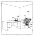
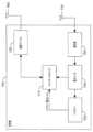
図1Aおよび図1Bに示すように、本発明は、マイクロ波エネルギーを介して、ラップトップコンピュータ102などの、電子/電気デバイスに無線充電および/または主電力を供給するためのシステム100aあるいはシステム100bを含む。システム100aあるいはシステム100bのいずれかにおいて、電力送信グリッド101aあるいは電力送信グリッド101bは、電源コンセントOに差し込まれた電力コードPを介して、AC主電源から動作電力を得ることができる。マイクロ波送信周波数は、好ましくは、適した波長を有する、FCCが規制していない使用可能な周波数である。その波長は、位相アレイ101aあるいは位相アレイ101bの分解能を制限することがあり得るので、システムが動作することができるその他の周波数の選択を制限するわけではないが、好ましい周波数は、5.8GHz(波長5.17cm)と判定されていて、その周波数は、部屋、公会堂などの規模の距離においてラップトップ、セル電話、PDAなどのデバイスの電力送信に適している。 As shown in FIGS. 1A and 1B, the present invention provides a
図1A乃至図3Bに示すように、マイクロ波エネルギーは、1または複数の適応位相マイクロ波アレイエミッタ204、即ち、アンテナまたはラジエータに接続された電力源300によって充電されるデバイスに集中する。本発明に従って、適応位相マイクロ波アレイエミッタ204からのマイクロ波エネルギーを、デバイスの位置を知る必要なくそのデバイスに集中させることが可能である。図1A、図1B、図3Aおよび図3Bに示すように、充電されるデバイス102内の、好ましい高効率のレクテナ340(レクテナは、マイクロ波エネルギーを直流(DC)電力に直接変換する整流アンテナである。そのようなデバイスは、当業者には周知であり、本明細書では詳述しない)は、マイクロ波エネルギーを受け取って整流し、コントロールロジック350によって判定される時に、それをバッテリー370の充電用および/またはデバイス102の主電力用に使用する。第1の実施形態において、無線電力源100aと充電されるデバイス102の電力受信機330bとの間の通信チャネルは、電力を送るのに使用される周波数以外の周波数で開かれる。 As shown in FIGS. 1A-3B, microwave energy is focused on devices that are charged by a
充電されるデバイス102は、通信チャネル110a上でレクテナ340において受信されたビームの信号強度を、電力受信機330bの通信デバイス360の送信機部からの信号を介して、システム100aの電力送信機330aの通信デバイス320の受信機部に中継する。この情報は、充電されるデバイス102によって報告されるときに、アレイ110aによってマイクロ波エネルギーの最大ビーム301が放射されるまで、マイクロ波アレイエミッタノード204の送信位相の出力を上げたり、出力を下げたり、調整したりするのにシステム100aのコントロールロジック310によって使用される。 The
所望の送信周波数の単一の電力源に接続された各エミッタ204は、π/2の倍数である、特定の位相差を用いて信号を送信することができる。π/2の位相増分は、単なる例示であり、π/4、π/8、π/16などの、他の位相増分も可能である。好ましくは、エミッタ204の動作をオフまたはオンにして所望の位相になるようにする以外は、電力は、調整されない。 Each
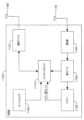
図2Aおよび図2Bで最も明確に示すように、垂直ケーブルと水平ケーブルは、各アレイノード204で交差する。この構成は、アレイ101aかアレイ101bのいずれかに適用する。垂直ケーブル202内で、ワイヤ210は、ゼロ位相の給電線である。ワイヤ212は、1/2π位相の給電線であり、ワイヤ209は、垂直制御線である。同様に、水平ケーブル200において、ワイヤ214は、π位相の給電線である。ワイヤ216は、3/2π位相の給電線であり、ワイヤ211は、水平制御線である。制御線209および211をコントローラ310に接続して、どの位相を所与のノード204上でアクティブにするかを制御することができる。単一のアンテナ制御をチップ206上で行うことができる一方、実際のノードラジエータまたはアンテナ208は、ノード204の幾何学的中心を囲む円形素子として形成される。単一のコントローラか複数のコントローラのいずれかは、電力送信グリッドのうちの1または複数を制御できることを理解されるべきである。 As shown most clearly in FIGS. 2A and 2B, the vertical and horizontal cables intersect at each
システム100a用のコントロールロジック310の例示的なアルゴリズムは、以下の通りになるであろう。(1)電力受信機330は、通信チャネル110aを使用して、近傍にある任意の送信機330aにその受信機の存在を宣言することができる。(2)電力送信機330aは、通信チャネル110a上でその送信機の存在を伝達して、その送信機のアンテナ208またはノード204のうちの1つのみを使用して送信を開始することができる。(3)電力受信機330bは、通信チャネル110a上で微弱信号を受信したことを確認することができる。(4)電力送信機330aは、ゼロのデフォルト位相にして別のアンテナ208またはノード204を作動させて、通信チャネル110a上で受信機330bに信号強度を求めることができる。(5)電力受信機330bは、受信した信号が以前よりも強い、同じ、または弱いことを示す信号を送信し返すことができる。(6)その信号が以前よりも弱いまたは同じである場合、コントローラ310は、ノード204における位相を1/2πに増加させて、別の信号強度を送信するように要求できる。(7)全位相に対してステップ5および6が繰り返される。(8)信号強度の増加が見られない場合、その特定のノード204の作動を終了させ、別のノードが、ステップ4から繰り返されるプロセスにおいて使用される。(9)すべてのエミッタのノードが使用中になるまでステップ4から6までが繰り返される。 An exemplary algorithm for
別の例において、ステップ(6)は、位相を弧度0、1/2π、および5π/4を含む3位相サイクルで増加させることを含む。この方法において、全正弦曲線のおおよその形が判定される。従って、ピーク電力の位相角度を判定することができる。さらに、同調アンテナが合計される時点から、次に加算されるアンテナの受信電力は、受信された総電力のわずかな割合になる場合がある。従って、2番目のアンテナを加算することにより、電力が4倍に増加する一方、101番目のアンテナを加算することにより、その受信された総電力の2%に増加して、1001番目のアンテナを加算することにより、その電力の0.2%に増加する。これは、調査されるアンテナから実際の電力ゲイン/損失を検出するのが困難になる場合がある。従って、検査サイクル中に、わずかなアンテナだけの出力を上げて、検査される各アンテナの位相を記憶することができる。全アレイの位相が決定されると、すべての素子を作動させて、電力を送出することができる。 In another example, step (6) includes increasing the phase in three phase cycles including
代替として、電力送信されるすべてのアンテナを再同調することができ、それは、アンテナの位相をそのアンテナの電流値付近にわずかに移動させて、受信した信号のインパクトを検出することによって可能である。再同調が1方向で(例えば、位相を前進または後退させて)改善する場合、どちらの側でも改善しなくなるまで位相のサイクル/増分が継続される。これは、大規模なアレイの受信電力レベルの変化を検出する能力に依存するであろうし、そうでなければ、すべてのアレイの電源を切り、位相を一から再構築するように要求されるかもしれない。 Alternatively, all power transmitted antennas can be retuned by slightly shifting the phase of the antenna around the current value of that antenna and detecting the impact of the received signal. . If the retuning improves in one direction (eg, by moving the phase forward or backward), the cycles/increments of phase continue until there is no improvement on either side. This will depend on the large array's ability to detect changes in received power levels and may otherwise require powering down all arrays and rebuilding the phase from scratch. unknown.
第2の実施形態において、図2Bおよび図3Bで最も明確に示すように、各アレイ素子またはノード204を、電力受信システム330bの較正送信機460から較正信号を受信するように設定することができる。各アレイ素子またはノード204は、そのノード204において検出された受信較正信号を、データ線303を介してコントロールロジック310に送信することができる。その後、最適化された電力送信301を電力受信機330bに送信し返すために、コントローラ310またはコントローラ206のいずれか、または両方のコントローラの組み合わせを、各アレイ素子またはノード204に対し、その素子用に検出された位相を送信位相として設定できる。実施形態100aおよび100bの両方において、充電されるデバイス102に最初に通信する必要はなく、アレイが特定の位置または「ホットスポット」に電力送信することを可能にするために、構成メモリデバイスをコントロールロジック310と通信可能な状態にすることができる。この機能は、充電されるデバイス102に通信チャネル110aまたは110bを確立する予備電力がない場合に、電力送信301を充電されるデバイス102に送信するときに有用である。 In a second embodiment, as shown most clearly in FIGS. 2B and 3B, each array element or
代替として、第2の実施形態は、送受信機にあるような、受信機とそれぞれの送信機アンテナとの双方向能力を利用する以下の動作を行うことができる。コントローラは、それぞれの送受信機に、電力受信機(即ち、充電されるデバイス)からビーコン信号を受信するように準備させることができる。その後充電されるデバイスは、ビーコン信号(例えば、位相調整アレイと同じ周波数にできる較正信号であり、例えば、そのアレイと受信機との間の無線通信を介してそれらのクロックに同期させる較正信号)を送信して、その信号は、充電されるデバイスと電力送信機との間のすべてのオープンパスをトラバースする。電力送信機で受信される信号は、受信機と、送信機の各アンテナに接続する送信機のアンテナとの間のすべてのオープンパスの合計に等しく、特定の電力レベルとそれぞれの特定の電力送信機アンテナの位相とが合計された各パスの合計である。 Alternatively, the second embodiment may take advantage of the bidirectional capabilities of the receiver and respective transmitter antennas as in the transceiver. The controller may prepare each transceiver to receive a beacon signal from the power receiver (i.e., the device being charged). The devices that are then charged are supplied with a beacon signal (e.g., a calibration signal that can be at the same frequency as the phased array and synchronized to their clock via wireless communication between that array and the receiver). The signal traverses all open paths between the device being charged and the power transmitter. The signal received at a power transmitter is equal to the sum of all open paths between the receiver and the transmitter's antennas that connect to each of the transmitter's antennas at a particular power level and each particular power transmission. This is the sum of each path in which the phase of the antenna is summed.
送信機アレイの各アンテナは、受信された位相を検出するために着信信号と内部信号を比較する。受信された位相がすべての送信機のアンテナによって確立されると、各アンテナは、その全出力を用いて、受信された位相を複素共役で送信し返す。 Each antenna in the transmitter array compares the incoming signal to the internal signal to detect the received phase. Once the received phase has been established by all transmitter antennas, each antenna uses its full power to transmit back the received phase in its complex conjugate.
さらに、上記のアレイの同調は、考えられるすべてのパスを考慮する(例えば、アレイと受信機との間で直接のオープンパスがあることまたは受信機が環境内を滑らかな直線運動で移動することを仮定していない)ので、環境の構成の変更は、移動される受信機または変更される電力送信機アレイの物理的構成に等しいであろう。従って、アレイの頻繁な再同調が絶えず要求されるであろう(例えば、1秒当たりの同調が10回以上になる)。 Additionally, the array tuning described above takes into account all possible paths (e.g., there is a direct open path between the array and the receiver or the receiver moves in a smooth linear motion through the environment). ), the change in the configuration of the environment will be equivalent to the physical configuration of the receiver being moved or the power transmitter array being changed. Therefore, frequent retuning of the array will be continually required (eg, 10 or more tunings per second).
アンテナの再同調は、受信機のビーコン信号を「リスン(listen)する」ために、送信される出力を停止するように要求されるので、アレイに電力を供給するのに使用されたであろう時間が損失する。従って、受信機への電力送出を最大にするために、アレイは、受信機の電力レベルが大きく変わらない場合、再同調の頻度を減らすことができる。受信機の電力の受け取りが低下する場合、アレイは、受信機の電力が再度安定するまで、更新の頻度を増やすことができる。同調の頻度に対する特定の制限を、最小10tsp(1秒当たりの同調)から最大500tpsなどにして設定できる。同調の頻度を著しくすると、電力転送の効率を下げる恐れがあるので、有用でない。 Antenna retuning would have been used to power the array since it would require stopping the transmitted power in order to "listen" for the receiver's beacon signal. Time is lost. Therefore, to maximize power delivery to the receiver, the array can retune less frequently if the power level of the receiver does not change significantly. If the receiver power reception decreases, the array can be updated more frequently until the receiver power stabilizes again. Certain limits on the frequency of tuning can be set, such as a minimum of 10 tsp (tunes per second) to a maximum of 500 tps. Increasing the frequency of tuning too much is not useful as it may reduce the efficiency of power transfer.
代替として、いくつかの数(n)のアンテナの同調を以下のように実行することができる。すべてのアンテナの電源を切ることができる。その後n個のアンテナのうちの1つの動作をオンにして、他のn個のアンテナのそれぞれが同調するための参照としてそのアンテナをそのままにする。その後残りのnアンテナのそれぞれの動作をオンにして、それらのアンテナの最適位相が記録され、その後それらのアンテナの動作をオフにする。このシーケンスがn番目のアンテナで実行されるときに、すべてのアンテナは、それぞれが最適位相で動作をオンにする。 Alternatively, tuning of some number (n) of antennas can be performed as follows. All antennas can be turned off. One of the n antennas is then turned on, leaving it as a reference for each of the other n antennas to tune to. The operation of each of the remaining n antennas is then turned on and the optimal phase of those antennas is recorded, and then the operation of those antennas is turned off. When this sequence is executed on the nth antenna, all antennas turn on, each with their optimum phase.
移動する受信機を有する第1の実施形態について、すべての送信機アンテナは、例えば、そのアンテナの位相をそのアンテナの電流値付近にわずかに移動させて、受信した信号のインパクトを検出することによって再同調される必要がある。再同調が1方向で改善する場合、位相のサイクル/増分は、どちらの側でも改善しなくなるまで継続する。これは、大規模なアレイの受信電力レベルの変化を検出する能力に依存するであろうし、そうでなければ、すべてのアレイの電源を切り、位相を最初から再構築するように要求されるかもしれない。 For the first embodiment with a moving receiver, all transmitter antennas are controlled by detecting the impact of the received signal, e.g. by slightly shifting the phase of its antenna around its current value. Needs to be re-tuned. If the retuning improves in one direction, the phase cycles/increments continue until there is no improvement on either side. This will depend on the large array's ability to detect changes in received power levels, and may otherwise require powering down all arrays and rebuilding the phase from scratch. unknown.
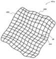
典型的なアレイ101aまたは101bは、1辺当たりおよそ1メートルの30×30のグリッド網とし、ワイヤの各交点は、単一の送信アンテナ204を有する。好適には、アレイグリッド101aまたは101bは、柔軟な/柔らかい素材で作られる。グリッド素材の柔軟性は、ユーザが、マイクロ波アレイエミッタグリッド101aまたは101bを実質的に不均等で同一平面上にない方法、即ち、平らにならないように広げて物理的に構成することができるようにして、例えば、平坦な二次元アレイによって生じる反射焦点、および個別の位相差を有する平坦で定期的に処理されるアレイで通常起こる盲点を最小にする。図1Aおよび1Bに示すように、アレイ101aまたはアレイ101bのいずれかは、鉢植えSなどの、支持構造物を覆うことができるように、好適には、不均等で同一平面上にない構成にするために十分柔軟である。 A
この方法において、位相アンテナに指向性があることによって、受信するデバイス102において受信することができる構造位相された(constructively phased)ビーム信号を介してゲインが発生するので、逆二乗の法則にうまく対応する。加えて、101aまたは101bなどの位相調整アレイの使用は、物理的指向性アンテナ、即ち、パラボラアンテナ、八木アンテナなどの、扱いにくく、外観の悪いデバイスを使用する必要性をなくす。さらに、環境を害し、または他の場所に位置するデバイスとの干渉を引き起こさないようにするために、電力送信プロセスの効率性によって、電磁(EM)信号をあらゆる所に広げることなくそのほとんどを受信するデバイスに近似の信号強度にすることができるように、低電力による送信が使用される。 In this way, the directional nature of the phased antenna creates a gain through a constructively phased beam signal that can be received at the receiving
信号が受信されて、その電力が使用可能になると、アンテナから来るおよそ5.80GHzのAC電流をDC電流に変換して、バッテリー370、蓄電キャパシタなどを充電するプロセスは、そのタスクを実行できる電圧の低い整流器で行われる。これらの整流器は、狭い範囲のショットキーダイオードに基づくか、または受信した信号と同じ位相の5.80GHzの発振回路との共振を利用することができるので、整流器の電力を、レクテナ340の整流器部で使用されるダイオードの電圧低下を克服する時点まで強めることができる。複数のビーム構成をシミュレートするために、複数のデバイスを、そのアレイを時間共有することによって、またはアンテナの位相を重ね合わせることによって充電できることに留意されたい。 Once the signal is received and its power is available, the process of converting the approximately 5.80 GHz AC current coming from the antenna into DC current to charge the
上記の充電メカニズムは、送信機と受信機が互いに通信しているときに動作する。しかし、通信する電力がない受信機を充電するための方法も有益である。これを実現するために、周期的な電力送信バーストを受信する1つの位置または複数の位置が確立されてよい。 The charging mechanism described above operates when the transmitter and receiver are communicating with each other. However, methods for charging receivers that do not have power to communicate are also useful. To accomplish this, one or more locations may be established to receive periodic power transmission bursts.
バッテリー電力がないデバイスを充電する方法の一例において、ビーコンデバイス、またはレザレクタ(resurrector)(図示せず)を、周期的な電力送信バーストを受信する位置またはユーザの要求に応じた位置に置くことができる。ビーコンデバイスは、ビーコン信号を送信するなどによって、電力送信グリッドと通信して、その電力送信グリッドは、そのビーコン信号位相の構成を、周期的な電力送信バースト(例えば、10分毎に1秒間のバースト、または10分毎に1秒間のバーストと同時に行う毎分0.1秒間のバースト)を送信する位置として認識する。ビーコンデバイスから送信されるビーコン信号は、その信号が電力送信グリッドに到達する前にさまざまな媒体を介して反射および/または屈折する。従って、複数のビーコン信号は、電力送信グリッドによって受信される。電力送信グリッドが1または複数のビーコン信号を受信すると、ビーコンデバイスの位置から電力送信グリッドまでのオープンパスが確立される。 In one example of a method for charging a device without battery power, a beacon device, or resurrector (not shown), may be placed in a position to receive periodic power transmission bursts or in response to a user's request. can. A beacon device communicates with a power transmission grid, such as by transmitting a beacon signal, such that the power transmission grid configures its beacon signal phase in periodic power transmission bursts (e.g., 1 second every 10 minutes). burst, or a burst of 0.1 seconds per minute performed at the same time as a burst of 1 second every 10 minutes) is recognized as the transmitting position. Beacon signals transmitted from beacon devices reflect and/or refract through various media before the signal reaches the power transmission grid. Accordingly, multiple beacon signals are received by the power transmission grid. When the power transmission grid receives one or more beacon signals, an open path is established from the location of the beacon device to the power transmission grid.
電力送信グリッドはその後、ビーコン信号を集めて、送信されたビーコン信号の波形を再現することができる。この再現された波形から、電力送信グリッドはその後、電力送信バーストを、例えば、再現された波形の逆波形として送信して、ビーコンデバイスによって確立された位置に電力バーストを供給することができる。一実施形態において、この逆波形は、ビーコンデバイスから受信された波形を複素共役、または数学的な等価変換を用いることによって判定されてよい。周期的な電力送信バーストを受信する位置が確立されると、ビーコンデバイスの動作をオフにすることができる。 The power transmission grid can then collect the beacon signals and recreate the waveform of the transmitted beacon signals. From this reconstructed waveform, the power transmission grid can then transmit power transmission bursts, eg, as an inverse waveform of the reconstructed waveform, to provide power bursts to the locations established by the beacon device. In one embodiment, this inverse waveform may be determined by using a complex conjugate, or mathematical equivalent transform, of the waveform received from the beacon device. Once a location for receiving periodic power transmission bursts is established, operation of the beacon device can be turned off.
バッテリー電力がない充電されるデバイス102を、その後、上記の充電プロセスを経るために電力送信グリッドと通信するのに十分な電力を有するまで、周期的な電力送信バーストを受信する位置に置くことができる。そのデバイスをその後、その位置」から移動することができる。 A
充電されるデバイス102がある位置から別の位置に移動されるか、または電力送信グリッドが移動されると、電力送信グリッドは、自身を再同調して(例えば、送信アンテナを再整列する)充電されるデバイス102への最適な電力送信を確立できる。この再同調は、電力の低下を報告するデバイス102に応答して、または定期的な間隔(例えば、1マイクロ秒-10秒間隔)で発生させることができる。しかし、定期的な間隔は、信号電力が受信機によって維持されている程度に応じて、短くまたは長くされてもよいし、一方で電力の低下にかかわらず定期的に再同調を継続してもよい。 When the
送信機アンテナは、さまざまな形状およびデザインで構成して使用できる細長い「位相ワイヤ」を作り出すために、回路を単一のチップに含めて、ワイヤでチップをデイジーチェーン接続する形をとることもできる。数千ものアンテナおよび「位相制御」チップの列を介して関連するコントローラを有する複雑なアレイを構築するには、チップ間のワイヤは、チップを共通のコントローラに接続するデータパスとして機能することができ、一方それと同時に、ワイヤは、自身を送信/受信アンテナとしても機能することができる。各チップは、アンテナとして機能する、チップから延びたより多くのワイヤを有することができる。各アンテナは、チップが他のアンテナから独立した各アンテナの位相を制御できるようにするアドレス(例えば、a、b、cなど)が付与されてもよい。さらに、ワイヤは、アレイの同調がアンテナの位置および配置に影響されないので、使用可能な空間に応じてあらゆる配置で構成されてよい。 The transmitter antenna can also take the form of daisy-chaining chips with wires, with the circuitry on a single chip, to create an elongated "phase wire" that can be configured and used in a variety of shapes and designs. . To build complex arrays with thousands of antennas and controllers associated through rows of "phase-controlled" chips, wires between the chips can act as data paths connecting the chips to a common controller. However, at the same time, the wire can also act as a transmitting/receiving antenna. Each chip can have more wires extending from the chip that act as antennas. Each antenna may be given an address (eg, a, b, c, etc.) that allows the chip to control the phase of each antenna independent of other antennas. Furthermore, the wires may be configured in any arrangement depending on the available space, since the tuning of the array is not affected by the position and placement of the antenna.
アンテナチップのコントローラは、短いワイヤを介して接続され、そのワイヤを、いくつかの方法でアンテナとして利用できる。例えば、ワイヤ自体は、発振器および/または増幅器によって駆動されてよいし、またはシールドをワイヤの周りに使用して、シールド自体を駆動してアンテナとして使用することができるので、通信ワイヤが多層アレイの信号を遮断するのを防ぐことができる。 The controller of the antenna chip is connected via a short wire, which can be used as an antenna in several ways. For example, the wires themselves may be driven by oscillators and/or amplifiers, or a shield can be used around the wires to drive the shield itself and use it as an antenna, so that the communication wires are in a multilayer array. This can prevent the signal from being blocked.
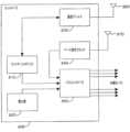
図4は、第1の代替的実施形態の電力送信機のブロック図である。送信機は、コントロールロジック410、位相シフタ420(Nカウント)、信号ジェネレータ/乗算器430、増幅器440(Nカウント)、および(N)アンテナ450を含む、アンテナコントローラ400であってよい。アンテナコントローラ400は、電力およびベース周波数制御信号、ならびに他のコマンドおよび通信信号を、すべてのアンテナコントローラを制御する単一のコントローラから、または前のアンテナコントローラ400からの共通バス上で受信する。例えば、電力信号は、送信機400の電源(図示せず)によって受信されてもよいし、一方、ベース周波数制御信号は、信号ジェネレータ/乗算器430によって受信されてもよいし、通信信号およびコマンドは、コントロールロジック410によって受信されてもよい。各々の前のアンテナコントローラ400が電力およびベース周波数制御信号を供給する場合において、それらの信号を搬送するバスは、次のアンテナコントローラ400まで継続することができる。コントロールロジック410は、位相シフタ420を制御して、増幅器440の位相を調整させるようにすることができる。信号ジェネレータ/乗算器は、バスからの信号を、例えば、10MHzで受信して、その信号を無線送信用に例えば、2.4、5.8GHzなどに変換する。 FIG. 4 is a block diagram of a first alternative embodiment power transmitter. The transmitter may be an
図5は、第2の代替的実施形態の電力送信機のブロック図である。送信機は、コントロールロジック510、位相シフタ520(Nカウント)、信号ジェネレータ/乗算器530、送受信機540(Nカウント)、(N)アンテナ550、および位相比較器560(Nカウント)を含む、アンテナコントローラ500であってよい。送受信機540は、受信機から較正信号またはビーコン信号を受信して、その信号を位相比較器560に転送する。位相比較器560は、位相比較器のそれぞれの送受信機540が受信した信号の位相を判定して、電力信号を送信する最適な位相角度を判定する。この情報は、コントロールロジック510に提供され、その後位相シフタ520に、送受信機の位相を(例えば、受信したビーコン/較正信号の複素共役で)設定して、その設定された位相で電力を送信するようにさせる。信号ジェネレータ/乗算器530は、実質的にアンテナコントローラ400の信号ジェネレータ/乗算器430と同様の機能を実行する。さらに、バス信号は、送信機400のバス信号と同様であり、例えば、送信機500の相当するコンポーネントによって受信される信号と同様である。 FIG. 5 is a block diagram of a second alternative embodiment power transmitter. The transmitter includes a
図6は、例えば、図4および図5のアンテナコントローラを制御するためのコントローラ600のブロック図である。コントローラ600は、コントロールロジック610、電力源620、アンテナ660に接続された通信ブロック630、アンテナ670に接続されたベース信号クロック640、およびバスコントローラ650を含む。コントロールロジック610は、Mバス上からの信号をM個のアンテナコントローラ(例えば、400および500)に送信する、バスコントローラ650を制御する。電力源620は、電力源をバスコントローラ650に供給する。通信ブロック630は、通信ブロックのそれぞれのアンテナ660を介して受信機からのデータを送受信する。ベース信号クロック640は、ベース信号を他のコントローラに送信し、受信機が同期するための送信も送信/受信することができる。1つのコントローラ600を利用して、すべての送信機アンテナを制御してもよいし、または1つのコントローラ600が一群のアンテナを制御する場所でいくつかのコントローラを使用してもよい。さらに、それぞれのアンテナを有している、別個の通信ブロックおよびベース信号クロックを示しているが、それらの機能性は、1つのブロック(例えば、通信ブロック630)に組み込まれてよいことに留意されたい。 FIG. 6 is a block diagram of a
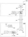
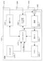
図7は、第1の実施形態に従った、代替的受信機700のブロック図である。受信機700は、コントロールロジック710、バッテリー720、通信ブロック730および関連するアンテナ760、電力メータ740、および整流器750および関連するアンテナ770を含む。コントロールロジック710は、通信ブロック730からのデータ信号をデータ搬送周波数で送受信する。このデータ信号は、上記のサイドチャネルを介して送信される電力強度信号の形式であってよい。整流器750は、電力送信機から電力送信信号を受信し、その信号は、電力メータ740を通って充電用のバッテリー720に供給される。電力メータ740は、受信した電力信号の強度を測定して、この測定値をコントロールロジック710に提供する。コントロールロジック710は、バッテリー720自体からバッテリーの電力レベルを受信することもできる。 FIG. 7 is a block diagram of an
受信機700は、例えば、コントローラ600がアンテナ670を介してベース周波数信号を送信することによって、コントローラ600と同期されてもよい。受信機はその後、この信号を使用してビーコン信号または較正信号を同期することができ、それらの信号は、受信機によってコントローラに送信し返される。この技術は、複数のコントローラにも利用されてよいことにも留意されたい。つまり、複数の送信アレイが利用されている場所で、コントローラは、コントローラのうちの1つから送信されたベース周波数信号を利用することによって、互いに同期されてよい。
図8は、第2の実施形態に従った、代替的受信機800のブロック図である。受信機800は、コントロールロジック810、バッテリー820、通信ブロック830および関連するアンテナ870、電力メータ840、整流器850、ビーコン信号ジェネレータ860および関連するアンテナ880、および整流器850またはビーコン信号ジェネレータ860を関連するアンテナ890に接続するスイッチ865含む。整流器850は、電力送信機から電力送信信号を受信し、その信号は、電力メータ840を通って充電用のバッテリー820に供給される。電力メータ840は、受信した電力信号の強度を測定して、この測定値をコントロールロジック810に提供する。コントロールロジック810は、バッテリー820自体からバッテリーの電力レベルを受信することもできる。コントロールロジック810は、通信ブロック830を介して、クロックを同期化するベース信号クロックなどの、データ信号をデータ搬送周波数で送信/受信することもできる。ビーコン信号ジェネレータ860は、アンテナ880またはアンテナ890のいずれかを使用して、ビーコン信号または較正信号を送信する。バッテリー820は、電力が受信され、その電力を受信機800に供給するために図示されているが、受信機は、その電力を整流器850から直接受信することもできることに留意されたい。この電力は、バッテリー820に充電電流(charging current)を供給する整流器850に加えてもよいし、または充電する代わりにされてもよい。さらに、複数のアンテナの使用は、一つの例示的な実装であり、その構造を1つの共有アンテナに縮小してもよい。 FIG. 8 is a block diagram of an
送信機のアンテナの制御回路と受信機の電力および制御回路を、集積チップ(IC)として組み込むことができ、いくつかの主要な回路コンポーネントを共有できるので、2つのチップの機能性を単一のチップとして設計することができ、異なるパッケージングまたは構成を選択することによって、そのチップは、送信機または受信機のいずれにも機能することができる。つまり、同じチップのある部分を機能させるまたは機能させないようにして、送信アンテナのコントローラまたは受信機のコントローラとして利用することができる。このことは、2つの異なるチップを組み立てて検査するコストを削減できるだけでなく、高額になりうるチップの製造コストも節約することができる。 The transmitter antenna control circuitry and the receiver power and control circuitry can be integrated as integrated chips (ICs) and share some major circuit components, combining the functionality of the two chips into a single It can be designed as a chip, and by choosing different packaging or configurations, the chip can function as either a transmitter or a receiver. That is, a portion of the same chip can be activated or deactivated and used as a transmit antenna controller or a receiver controller. This not only reduces the cost of assembling and testing two different chips, but also saves on chip manufacturing costs, which can be expensive.
上記のように、送信グリッドの形状は、さまざまな種類であってよい。従って、アンテナのパッキング(packing)は、およそ送信される電力信号の波長の半分からその波長の数倍まで十分対応できるであろう。二次元配置は、アレイがカーペットの下に平らに敷かれ、屋根裏の断熱材を覆うことも可能である。例えば、複数の送信アンテナを包含する複数のワイドワイヤ(例えば、細長い2次元アレイ)を採用してもよい。これらのワイドワイヤを床または壁の中に設置することも可能である。代替として、電力送信グリッドは、ループアンテナの形状、またはその他の形状にすることも可能である。 As mentioned above, the shape of the transmission grid may be of various types. Therefore, the packing of the antenna will be sufficient to accommodate approximately half the wavelength of the transmitted power signal to several times that wavelength. A two-dimensional arrangement is also possible where the array is laid flat under the carpet and covered with attic insulation. For example, multiple wide wires (eg, an elongated two-dimensional array) containing multiple transmit antennas may be employed. It is also possible to install these wide wires in the floor or in the wall. Alternatively, the power transmission grid may be in the form of a loop antenna or other shape.
三次元配置は、最大数のアンテナをパックすることができ、オフィスの天井タイル、ドア、絵およびテレビなどの、便利な形状に組み込むことができる。従って、アレイを見えないように、目立たないようにする。さらに、グリッドアレイは、いくつかの層が互いに重なった形状にすることができるので、高密度のアンテナが実現可能である。この例において、アレイは、単一の転送ビームの背面の反射ビームを最小にする「位相体積」と同様の働きをする。反射ビームは、位相体積の厚さが増すにつれて減衰する。 Three-dimensional arrangements can pack the maximum number of antennas and can be incorporated into convenient shapes, such as office ceiling tiles, doors, paintings, and televisions. Thus, making the array invisible and unobtrusive. Additionally, grid arrays can be shaped with several layers stacked on top of each other, so high antenna densities are possible. In this example, the array acts similar to a "phase volume" that minimizes the reflected beam on the backside of a single transmitted beam. The reflected beam is attenuated as the thickness of the phase volume increases.
つまり、全指向性アンテナを使用した完全に平坦な位相調整アレイは、(例えば、自由空間またはアレイの反対側で同一の環境がある場合)アレイ面の周りで対称的に形成された波面の2つの「像」を作り出す。これは、電力送出が減少する望ましくない結果になるおそれがある(例えば、背面に流れる電力が50%になる)、従って転送効率が低下する。アレイアンテナを同一平面上にない形式で配置することは、この対称波面が、たとえ三次元アレイの対称デザインであっても、アンテナがアレイの対称面で異なる位相を有し、その信号が非対称および非「反射」になるという事実によって、対称波面が減衰する。 In other words, a perfectly flat phased array using an omnidirectional antenna will have two wavefronts formed symmetrically around the array plane (e.g., in free space or with the same environment on opposite sides of the array). Create two "images". This can have the undesirable result of reduced power delivery (eg, 50% power going to the back side), thus reducing transfer efficiency. Placing the array antenna in a non-coplanar manner means that this symmetrical wavefront, even in the symmetrical design of a three-dimensional array, means that the antenna will have a different phase in the plane of symmetry of the array and its signal will be asymmetric and The fact that it becomes non-"reflective" causes the symmetrical wavefront to be attenuated.
アレイの位相が特定の受信機用に同調される場合、アレイのそれぞれのアンテナは、その特定の受信機に到達する信号を生成するために送信する特定の位相を有する。2以上の受信機を、以下の技術のうちの1つまたはその組み合わせによって電力を受信するように構成することができる。 When the phase of the array is tuned for a particular receiver, each antenna in the array has a particular phase to transmit to produce a signal that reaches that particular receiver. The two or more receivers may be configured to receive power by one or a combination of the following techniques.
第1の技術において、電力送出の時間共有を異なる受信機間で利用することができる。これは、アレイのアンテナを1つの受信機に同調させて、その後次の受信機に移行し、各受信機に均一な(または不均一な)時間量を付与することによって行うことができる。アレイを各受信機に同調させることは、メモリから行われるか、または第2の実施形態と同様のプロセスを用いてアレイを再同調することによって行われる。 In the first technique, time sharing of power delivery can be utilized between different receivers. This can be done by tuning the antennas of the array to one receiver and then transitioning to the next, giving each receiver a uniform (or non-uniform) amount of time. Tuning the array to each receiver is done from memory or by retuning the array using a process similar to the second embodiment.
別の技術において、すべてのアレイアンテナの位相を変調して複数の電力スポットを生成する技術を利用することができる。各アンテナに対し、受信信号は、受信角度である位相のベクトル信号であり、一方その強度は、受信信号の電力レベルである。複数のアンテナに戻る信号を生成するために、送信の位相は、受信ベクトルの合計角度として判定される。受信信号の強度を利用して、通常の送信電力で各アンテナから送信する必要がないかもしれないが、マルチパス信号が考慮されるときに良く機能する多焦点偏向信号(biased multi-focus signal)を生成するために、各受信機からピーク受信信号電力を見つけ出して、ベクトル加算は、正規化スケール(例えば、各受信機からのピーク電力をそのピーク電力に対して強度1.0と見なす)と対照にベクトルをスケーリングすることによって偏向される。ベクトルの加算は、各アンテナが、より多くの電力を送出しまたはより多くの電力を受信する受信機に、より多くの電力を供給することを確保する。 Another technique may utilize a technique that modulates the phase of all array antennas to create multiple power spots. For each antenna, the received signal is a vector signal whose phase is the reception angle, while its strength is the power level of the received signal. To generate signals back to multiple antennas, the phase of the transmission is determined as the sum angle of the receive vectors. A biased multi-focus signal that takes advantage of the strength of the received signal and may not need to be transmitted from each antenna at normal transmit power, but works better when multipath signals are taken into account. Find the peak received signal power from each receiver to produce Deflected by scaling the vector to the contrast. Vector addition ensures that each antenna provides more power to the receiver, which transmits more power or receives more power.
アンテナの共有がもう1つの技術である。アレイ全体を複数のサブアレイに分割することによって、各アレイは、その電力を特定の受信機に割り当てることができる。この手法は、アレイが分割されるときに、当該アレイが効率のよい十分な大きさであるときに有益であろう。 Antenna sharing is another technique. By dividing the entire array into multiple subarrays, each array can allocate its power to specific receivers. This approach may be beneficial when the array is large enough to be efficient when it is partitioned.
別個のアレイは、統一して使用されてもよく、そこにおいて個々のアレイのユニットは、そのベース信号クロックを共有無線周波数を使用して同期して、すべての「スレーブ(slave)」送信機のコントローラユニットがそれらの波形をコヒーレントに合計できるようにする、指定された「マスタ(master)」ユニットから連続信号を得る。これによって、別個のアレイが環境内で分散されることが可能になり、ユーザが、建物、住居、製造工場またはオフィスの周囲に複数のアレイを柔軟に配置することができる。これらのコントローラの起動中、インストーラ/マネージャは、どんなに多くのアレイが不具合になっても、システムが、使用可能なアレイを使用して機能を継続するようにする、フェイルオーバーシーケンスと共にマスターユニットを指定することによって、異なるコントローラアレイを互いにリンクさせることができる。例えば、アレイは、原子時計を使用してそれらを同期することによって設定されてよい。つまり、別個のアレイユニットが、電力送信に使用する単一の周波数を利用する場合、別個のアレイユニットは、精密な原子時計(例えば、1:10^10より高い精度)を使用することによって、ベース周波数に同期せずに機能することができる。この場合、それらのアレイユニットは、数分の1秒で同位相になり、位相/信号のコヒーレンスを維持することが可能になるであろう。 Separate arrays may be used in unison, where the individual array units synchronize their base signal clocks using a shared radio frequency to synchronize all "slave" transmitters. Obtain continuous signals from a designated "master" unit that allows the controller unit to coherently sum their waveforms. This allows separate arrays to be distributed within the environment, giving users the flexibility to place multiple arrays around a building, residence, manufacturing plant, or office. During startup of these controllers, the installer/manager specifies a master unit with a failover sequence that ensures that no matter how many arrays fail, the system continues to function using available arrays. By doing so, different controller arrays can be linked together. For example, arrays may be set up by synchronizing them using atomic clocks. That is, if the separate array units utilize a single frequency for power transmission, the separate array units can Can function without synchronization to base frequency. In this case, the array units would be able to be in phase in a fraction of a second and maintain phase/signal coherence.
別の電力送信技術において、送信機は、その存在をすべての受信機にブロードキャストするサイド通信チャネルで通常の信号を送信する。その送信機は、近くに他の送信機がある場合、取り決めた周波数のうちの1つを使用することを確保するか、または他の送信機の信号をモニタすることによって信号の衝突を避ける。このようなブロードキャスト告知は、1分当たり数周波数から1分当たり1未満の周波数まで異なる場合がある。受信機は、その存在を告知する信号を送信することができ、送信機は、どの受信機が電力転送に最も適しているかを見つけるためにネゴシエートすることができる。ひとたび決まると、受信機は、単一の送信機を「ロック」する。これは、各送信機が、論理的(単一のコントローラ)デバイスとして定義されることを要求することができる。そのデバイスを複数にリンクされた送信機から構成することが可能である。コントローラが、電力エンベロープ(power envelope)が変更した(即ち、受信機が同じ電力を要求していない)ことを検出する場合、コントローラは、受信機が機能を停止しないように、電力の供給を継続することができる。 In another power transmission technique, the transmitter sends a regular signal on a side communication channel that broadcasts its presence to all receivers. The transmitter avoids signal collisions by ensuring that it uses one of the negotiated frequencies or by monitoring the signals of other transmitters when there are other transmitters nearby. Such broadcast announcements may vary from a few frequencies per minute to less than one frequency per minute. The receiver can transmit a signal announcing its presence, and the transmitter can negotiate to find out which receiver is most suitable for power transfer. Once determined, the receiver "locks" to a single transmitter. This may require that each transmitter be defined as a logical (single controller) device. It is possible for the device to consist of multiple linked transmitters. If the controller detects that the power envelope has changed (i.e., the receiver is not requesting the same power), the controller continues to provide power so that the receiver does not stop functioning. can do.
別の電力送信技術において、送信機を、電力を求めている任意のデバイスに電力を供給するために開放するように設定することができ、またはそれらの送信機が供給しなければならないデバイスと「ペアになる」ことができる。ペアリングは、送信機の所有者の観点から、効率性に影響を与えるおそれのある、近隣機同士から無意識に借りる電力の問題を回避する。送信機が複数の受信機と衝突する場合、送信機は、電力を最も必要とするデバイスに最初に電力を供給するなどの、順位の優先度付けを確立することを求めてよいし、それを1または複数の所定の基準で確立することもできる。 In another power transmission technique, transmitters can be configured to be open to powering any device that is seeking power, or the devices that they must supply. can be paired. Pairing avoids the problem of unintentionally borrowing power from neighboring machines, which can affect efficiency from the transmitter owner's perspective. If a transmitter collides with multiple receivers, the transmitter may seek to establish order prioritization, such as providing power to the devices that need it most first. It can also be established on one or more predetermined criteria.
例えば、いくつかの基準は、以下を含む。デバイスは、その所有者にとって(例えば、セル電話はおもちゃとは対照的に)非常に重要であることと、デバイスは、典型的には、送信機の近くで一日中何もしない(例えば、セル電話と比較したテレビのリモート制御)ことはないことと、デバイスは、すぐに電力を供給する必要があり、そうしないと機能が停止すると見なされること、を含む。そのようなデバイスは、危機的でない電力に達するまで、他のデバイスよりも高い優先度が付与されてよい。代替として、ユーザがカスタマイズした優先度が利用されてもよく、それによって、ユーザは、どのデバイスに最も高い優先度を与えるべきかを決定する。 For example, some criteria include: The device is very important to its owner (e.g., a cell phone as opposed to a toy), and the device typically does not do anything near its transmitter all day (e.g., a cell phone (as compared to TV remote control) and that the device must be powered immediately or it will be considered non-functional. Such devices may be given higher priority than other devices until non-critical power is reached. Alternatively, user-customized priorities may be utilized, whereby the user determines which devices should be given the highest priority.
上記の例示的な優先度付けの選好は、送信機システム(例えば、コントロールロジックにおいて)に事前にインストールされてよく、アレイのインストーラによって却下される(overruled)能力を用いて、システムが所有者/ユーザの優先度付けで送出することを確保する。所有者またはユーザは、アレイを開放して任意のデバイスに電力を送出するかどうかを望んでもよいし、または特定のデバイスを、優先度が最も高いまたは優先度が最も低いデバイスとして登録することを望んでもよい。さらに、ユーザまたは所有者は、特定のデバイスが動いていても、そのデバイスに電力の供給を維持するか否かを判定することを望んでよい。 The above exemplary prioritization preferences may be pre-installed on the transmitter system (e.g., in the control logic), with the ability to be overruled by the array installer, so that the system Ensure user-prioritized sending. The owner or user may wish to open the array to send power to any device, or may wish to register a particular device as the highest or lowest priority device. You may wish. Additionally, a user or owner may wish to determine whether to maintain power to a particular device even if the device is in motion.
第2の実施形態のアレイ同調アルゴリズムにおいて、電力の送信は、アレイが受信機の新しい位置に再同調する時に停止されなければならない。受信機の高速移動のためまたは環境の構成の素早い変化のために、このような再同調の動作が高周波数で行われる場合、新しいビーコン信号を受信する間にアレイの動作をオフにし続けるのに必要な時間によって、電力送出の効率が低下するおそれがある。従って、これに対抗するために、2以上の周波数をアレイ/受信機によって使用することができる。1つの周波数が同調されている間、もう1つの周波数は、電力の送信を継続することができ、その後、後続の周波数は、すべての周波数が再同調されるまで同調されるので、送信によって停止されるギャップを回避することができる。 In the array tuning algorithm of the second embodiment, power transmission must be stopped when the array retunes to the new position of the receiver. If such retuning operations are performed at high frequencies, due to fast movement of the receiver or rapid changes in the configuration of the environment, it may be necessary to continue turning off array operation while receiving new beacon signals. The required time can reduce the efficiency of power delivery. Therefore, more than one frequency can be used by the array/receiver to counter this. While one frequency is tuned, another frequency can continue transmitting power and then subsequent frequencies are stopped by transmitting as they are tuned until all frequencies are retuned. gap can be avoided.
大規模な位相調整アレイを設計するときに、要求される周波数をそれぞれのアンテナに送信することは、ケーブル(例えば、同軸ケーブル)の数が多いために困難になるかもしれない。これは、アンテナの数が1000を超える場合にさらに困難になるかもしれない。従って別の代替において、高周波数信号(>1GHz)をすべてのアンテナに送信する代わりに、低周波数信号(~10MHz)をすべてのアンテナを介して送信することができ、それぞれのアンテナは、位相ロックループ(PLL)および位相シフタなどの、周波数乗算回路を有するであろう。 When designing large phased arrays, transmitting the required frequencies to each antenna may be difficult due to the large number of cables (eg, coaxial cables). This may become even more difficult when the number of antennas exceeds 1000. Therefore, in another alternative, instead of transmitting a high frequency signal (>1 GHz) to all antennas, a low frequency signal (~10 MHz) can be transmitted through all antennas, each antenna being phase-locked. It will have frequency multiplier circuits, such as loops (PLLs) and phase shifters.
さらに、電力を受信して、自身で再充電する能力を有する標準フォーマットのバッテリー(例えば、AA、AAA、C-バッテリー、D-バッテリーなど)は、電子/電気デバイスに使用される使い捨ての(disposable)または再充電可能なバッテリーに代わるものとして望ましいであろう。これは、バッテリーが、送信機アレイと通信するのに必要なすべての回路を有するだけでなく、バッテリーが供給するデバイスを稼動させるのに使用される充電/エネルギーのキャパシタンスを有することが必要になるであろう。 Additionally, standard format batteries (e.g., AA, AAA, C-battery, D-battery, etc.) that have the ability to receive power and recharge themselves are disposable batteries used in electronic/electrical devices. ) or would be desirable as an alternative to rechargeable batteries. This requires that the battery not only have all the circuitry necessary to communicate with the transmitter array, but also have the charge/energy capacitance used to power the devices it supplies. Will.
デバイスは、コンポーネントを活性化するための電圧または電流、または単一のバッテリーの能力を上回る、バッテリー交換までの長時間の動作を確保するためのバッテリーのキャパシタンスを要求することが多い。従って、複数のバッテリーは、直列または並列で使用されることが多い。しかし、単一の受信機のバッテリーでは、デバイスの動作に必要なバッテリーは1つのみであり、そのバッテリーは、必要な電圧を送出することができ、そのバッテリーを充電する必要なく永久的に動作を維持する大量のエネルギーを受信できるので、エネルギー容量は、議論の余地のある問題になる。 Devices often require voltage or current to energize components, or battery capacitance to ensure long-term operation between battery replacements, which exceeds the capabilities of a single battery. Therefore, multiple batteries are often used in series or in parallel. However, with a single receiver battery, only one battery is required for the operation of the device, and that battery can deliver the required voltage and can operate permanently without the need to recharge the battery. Since large amounts of energy can be received to sustain the energy capacity, energy capacity becomes a controversial issue.
しかし、いくつかのバッテリーの代わりに単一のバッテリーを使用することは、デバイスのバッテリー記憶領域の構成のために、動作しないかもしれない。従って、これを克服するために付加的な技術を採用することができる。 However, using a single battery instead of several batteries may not work due to the device's battery storage configuration. Therefore, additional techniques can be employed to overcome this.
図9は、受信機バッテリーシステム900のブロック図である。システム900は、少なくとも1つの受信機バッテリー910を含み、任意の数の空バッテリー920を含んでもよい。例示目的として、1つの受信機バッテリー910と2つの空バッテリー920を示しているが、任意の数のバッテリーが利用されてよいことに留意されたい。受信機バッテリー910は、電力キャパシタ911、制御回路912、および電圧制御発振器913を含む。空バッテリー920は、インダクションロジック(induction logic)921を含む。 FIG. 9 is a block diagram of a
従って、バッテリーシステム900は、以下の通りに動作することができる。「受信機」が使用可能なバッテリー(即ち、910)を有する1つのみのバッテリーが供給される。しかし、性能の良いバッテリーと直列に置かれて使用される通常のバッテリーは、時間とともに抵抗が生じることもあり、とりわけ起こり得る問題として、通常のバッテリーは、バッテリーの使用期限が過ぎると漏電するおそれがある。 Accordingly,
代替として、「空」バッテリー(即ち、920)を、「電力セレクタ」とともに受信機バッテリー910上で使用することができる。一つの例の空バッテリー920は、正確なバッテリー寸法(battery dimensions)を有するデバイスであるが、アノードが短いので、受信バッテリー910の電圧によってそのデバイスを自力で駆動させる。受信機バッテリー910は、制御回路またはスライダ912または他の選択機構を利用して、ユーザが取り替えるバッテリーの数をユーザが選択することが可能にさせる。受信機バッテリー910は、その後、空バッテリー920を補うのに望ましい電圧を出力する。 Alternatively, an "empty" battery (ie, 920) can be used on the
別の技術において、知的空バッテリー920ならびに知的受信機バッテリー910を使用することができる。受信機バッテリーは、最初に、1KHz(または同様の他の周波数)の低電圧発振(<0.1V発振を、使用される空バッテリーの数を検出する期間で用いる)と同じ程度の所望のフォーマット1つのバッテリーの電圧を出力し、知的空バッテリー920は、1KHzを使用して自身に誘導して電力を供給する。空バッテリーは、抵抗、キャパシタンスまたは受信機バッテリーが検出することができる他の手段によって、電力線に効果(effect)を発生させる。知的空バッテリー920の周波数の効果は、静的付加である特性を有する内蔵擬似乱数ジェネレータ(例えば、論理921)によって行われる。従って、擬似ランダムジェネレータのカウントを電力線上で判定することができる。このうちの1つの実施形態では、電力線上で効果「ブリップ」をトリガするのに使用されるシフトビットなどの、周知の間隔で実行する32ビット線形フィードバックシフトレジスタが使用されるであろう。フィードバックシフトレジスタを出力するシード番号は、統一して機能しないように、すべての空バッテリー920上で異なる番号にしなければならない。 In another technique, an intelligent
図10は、「ブリップ」1010を含む、例示的なバッテリーシステムの電力線の図1000である。受信機バッテリー910は、電力線上でブリップ1010をカウントして、知的空バッテリー920の数を判定する。ブリップ1010は、高周波数パルスまたはキャパシタンス修正器になり得る。ほとんどの電子/電気デバイスによってマスクアウトされないブリップが選択される。このプロセスは、例えば、1ミリ秒未満の短い時間期間で実行される。その後、受信機バッテリー910は、異なる電力が必要な異なるデバイスで行われる次の出力増(power-up)まで電圧の検出を要求しない。受信機バッテリー910によって生成される1KHz「電力」周波数が停止して、空バッテリー920は、休止状態になり、電力が供給されるデバイスに透過的になる。 FIG. 10 is a diagram 1000 of an exemplary battery system power line, including a “blip” 1010.
再度図10を参照するが、ランダムブリップ1010は、システム900の電力システム線を介して2つの空バッテリー920のそれぞれによって生成される。ランダムブリップ1010を使用して、受信機バッテリー910によってランダムブリップジェネレータの数を判定する。ブリップを時間でカウントして、単一の空バッテリー920から予想される数で割ることによって、直列で設置される空バッテリー920の数を判定することができる。しかし、並列のバッテリー設置システムにおいて、並列の電力線毎に1つの受信機バッテリー910が要求される。 Referring again to FIG. 10,
デバイスが上記の500MHzを超える高周波数で電力を受け取る場合、受け取る位置は、(入ってくる)放射のホットスポットになる場合がある。従ってデバイスが人の手にある時、放射のレベルは、FCCの規制の範囲を超えるか、または医療/産業局によって設定された受け入れ可能な放射レベルを超えるかもしれない。過剰照射の問題を回避するために、デバイスは、加速度計などのモーション検出機構または同等の機構を統合することができる。デバイスが、移動中であると検出すると、デバイスが手荒に扱われていると仮定することができ、アレイにデバイスへの電力送信を停止するか、受信可能な電力の一部に受信される電力を低下させるいずれかの信号をアレイにトリガする。デバイスが車、電車または飛行機などの移動環境で使用される事例において、デバイスにすべての使用可能な電力がほとんど残ってない場合を除いて、電力は、断続的または低下したレベルでのみ送信されるかもしれない。 If the device receives power at high frequencies above 500 MHz, the receiving location may become a hotspot for (incoming) radiation. Thus, when the device is in a person's hands, the level of radiation may exceed the limits of FCC regulations or the acceptable radiation levels set by the Bureau of Health/Industry. To avoid over-irradiation problems, the device can integrate motion detection mechanisms such as accelerometers or equivalent mechanisms. When a device detects that it is moving, it can assume that the device is being mistreated and the array stops sending power to the device or reduces the received power to a fraction of the receivable power. Trigger any signal to the array that lowers the value. In instances where the device is used in a mobile environment such as a car, train, or airplane, power is only transmitted intermittently or at reduced levels, unless the device has almost all available power remaining. Maybe.
図11は、上記のようなモーション検出を含む第1の実施形態に従った、代替的受信機1100である。受信機1100は、コントロールロジック1110、バッテリー1120、通信ブロック1130および関連するアンテナ1160、電力メータ1140、整流器1150および関連するアンテナ1170、およびモーションセンサ1180を含む。モーションサンサ1180を除いて、残りのコンポーネントは、受信機700のそれぞれのコンポーネントと同様の機能で動作する。モーションセンサ1180は、上記のようなモーションを検出して、上記の技術に従って動作するための信号をコントロールロジック1110に送信する。 FIG. 11 is an alternative receiver 1100 according to the first embodiment that includes motion detection as described above. Receiver 1100 includes
図12は、上記のようなモーション検出を含む第2の実施形態に従った、代替的受信機1200である。受信機1200は、コントロールロジック1210、バッテリー1220、通信ブロック1230および関連するアンテナ1170、電力メータ1240、整流器1250、ビーコン信号ジェネレータ1260および関連するアンテナ1280、および整流器1250またはビーコン信号ジェネレータ1260を関連するアンテナ1290に接続するスイッチ1265を含む。モーションサンサ1280を除いて、残りのコンポーネントは、受信機800のそれぞれのコンポーネントと同様の機能で動作する。モーションセンサ1280は、上記のようなモーションを検出して、上記の技術に従って動作するための信号をコントロールロジック1210に送信する。 FIG. 12 is an
セル電話またはメディアプレーヤなどの、WiFi通信またはBluetooth(登録商標)などによって使用される周波数で電力を受信するように設計されたデバイスは、電力送信周波数で電力を受信する能力があるアンテナをすでに有しているかもしれない。従って、電力を受信する付加的なアンテナを有する代わりにWiFi通信などに使用される同じ通信アンテナを使用して、必要な回路を通信ハードウェアに付加する(例えば、整流回路、コントロールロジック回路などを付加する)ことによって電力を受信することができる。 Devices designed to receive power at frequencies used, such as those used by WiFi communications or Bluetooth, such as cell phones or media players, already have an antenna capable of receiving power at the power transmission frequency. You may be doing it. Therefore, instead of having an additional antenna to receive power, the same communication antenna used for WiFi communication etc. can be used and the necessary circuitry added to the communication hardware (e.g. rectifier circuit, control logic circuit, etc.) power can be received by adding
無線電力送信システムのいくつかの使用例は、商品の棚に値札を付けるスーパーマーケットまたは消費者用小売店を含む。これらの値札の価格番号を管理することは、費用がかかり、手間を要する作業になる。さらに、特売品および宣伝広告では、値札が日々変更されることになる。 Some examples of uses for wireless power transmission systems include supermarkets or consumer retail stores that place price tags on shelves of merchandise. Managing the price numbers of these price tags can be an expensive and time-consuming task. Additionally, price tags for special offers and advertisements may change daily.
今日の電子インク標識を用いれば、各値札を価格/広告宣伝をかなり効果的に表示する小型の電子デバイスで作ることが可能であり、電子インクは、静的画像を表示する間は電力をまったく消費しない。しかし、電力は、新しいデータを表示するのに要求され、さらに電子インク標識を変更するのにも電力が必要である。ワイヤをそれぞれのタグにつなげるのは、実現可能な解決策でもなければ、各値札にバッテリーを入れるのも実現的ではない。それは、定期的な充電または交換が必要になるからである。無線電力送信を利用することによって、数千もの値札を、天井または棚に置かれた無線送信機アレイによって動作可能に維持する、つまり、値札を定期的に充電するならびに値札が移動した時に充電することができる。値札が所望の目的場所に置かれると、その値札を、初期電力を用いて有線または無線のいずれかで活性化することができる。 With today's electronic ink signs, each price tag can be made with a small electronic device that displays the price/promotion quite effectively, and the electronic ink consumes no power while displaying a static image. Don't consume. However, power is required to display new data, and power is also required to change electronic ink indicia. Connecting a wire to each tag is not a viable solution, nor is putting a battery in each tag. This is because periodic charging or replacement is required. By utilizing wireless power transmission, thousands of price tags are kept operational by a wireless transmitter array placed on the ceiling or on a shelf, which charges the tags periodically as well as when they are moved. be able to. Once the price tag is placed at the desired destination location, the price tag can be activated either wired or wirelessly using the initial power.
別の例において、製造工場は、多数のセンサおよびコントローラを利用して、製造、製造される商品全体の生産性および品質を同時に維持する。無線通信の使用にかかわらず、それは、いまだにそれぞれのデバイスにワイヤを搬送する電力を稼動しなければならず、それによってデバイスが1または複数のコンポーネントに依存して、不具合になる傾向になり、例えば、石油製油所などの、かなり燃えやすい環境で使用するデバイスが設置される前に、デバイスに電線を通す穴をあける必要であるので、デバイスを密封することができない。従って、このようなデバイスに上記の無線電力受信機のうちの1つを組み込むことによって、無線の電力を供給することができる。 In another example, a manufacturing plant utilizes multiple sensors and controllers to simultaneously maintain productivity and quality of the overall manufactured goods. Regardless of the use of wireless communication, it still has to run power carrying wires to each device, thereby making the device dependent on one or more components and prone to failure, e.g. Before the device is installed for use in highly flammable environments, such as oil refineries, it is not possible to seal the device because holes must be drilled through it to pass electrical wires. Thus, by incorporating one of the wireless power receivers described above into such a device, it can be provided with wireless power.
無線電力システムは、モーション検出にも利用されてよい。電力送信システムが起動しているときに、環境内の小さな外乱は、転送の効率を変化させることがあり、その変化が送信の見通し線にない場合もある。この無線電力システムは、環境内の複数のパス(マルチパス)を活用するので、それをモーション検出器として使用することができる。ローカライズされたまたは環境に分散されたアレイから受信される電力を測定することによって、受信された電力レベルのどの変化も、環境の電磁構成の変更の表示になる。そのような使用において、ワイヤが受信機に電力を供給することができるので、電力転送レベルは非常に低くなるが、アレイを同調する手段としてのみ動作することに留意されたい。環境の構成の変化が検出されると、セキュリティシステム/アラームは、その変化を通知できる。 Wireless power systems may also be utilized for motion detection. When a power transmission system is activated, small disturbances in the environment can change the efficiency of the transfer, and the change may not be in the line of sight of the transmission. This wireless power system exploits multiple paths (multipath) in the environment, so it can be used as a motion detector. By measuring the power received from a localized or environmentally distributed array, any change in the received power level becomes an indication of a change in the electromagnetic configuration of the environment. Note that in such use, the power transfer level will be very low as the wire can power the receiver, but will only act as a means of tuning the array. When a change in the configuration of the environment is detected, the security system/alarm can notify you of the change.
別の例において、中身の温度が規制される個々の飲料および食べ物の容器は、常に電力源が必要である。このような容器が頻繁に移動する場合、電力源の可用性を維持することが困難になる。無線電力を使用して、電力源の可用性を維持することができるので、容器の温度を望ましい温度に維持することができる。容器を、使用可能な電力を使用して、中身の温度、中身の液量または重量を報告するのに使用することもできる。この例として、冷たい/熱い飲み物が暑い日に出される場合、またはそれらを飲むときに冷たい/熱いのが最良である場合、この能力を用いれば、飲む人は、自分達の飲み物が周囲の温度に達する前に飲み終える必要がないばかりか、長期間自分達の飲み物を楽しめる。さらに、飲み物が減りだすと、ホスト役は、信号受信機を介して無線で通知されることがでるし、飲み物がなくなる前に注ぎ足すことができる。 In another example, individual beverage and food containers whose contents are temperature regulated require a constant power source. If such containers are frequently moved, it becomes difficult to maintain the availability of power sources. Wireless power can be used to maintain the availability of a power source, thereby maintaining the temperature of the container at a desired temperature. The container can also be used to report the temperature, volume or weight of the contents using the available power. As an example of this, if cold/hot drinks are served on a hot day, or if they are best served cold/hot, this ability allows the drinker to know that their drink is at the ambient temperature. Not only do they not have to finish their drink before it reaches the point, they can enjoy their drink for a longer period of time. Additionally, if the drink is running low, the host can be notified wirelessly via the signal receiver and can refill the drink before it runs out.
別の例において、電力受信機を使用してデバイスの電力使用量をモニタすることができるときに、デバイスの機能が停止する前に機能が低下したデバイスを検出することが可能である。例えば、火災報知器は、その報知器が使用する公称電力を消費していないときに機能が停止したと見なされてもよく、またはデバイスの機能が停止する寸前に通常起きる、デバイスの電力消費が急激に変化するときに、デバイスの機能が停止したと見なされてもよい。 In another example, when a power receiver can be used to monitor the power usage of a device, it is possible to detect a degraded device before the device stops functioning. For example, a fire alarm may be considered to have stopped functioning when it is not consuming the nominal power that the alarm uses, or when the device's power consumption increases, which typically occurs just before the device stops functioning. When there is an abrupt change, the device may be considered to have stopped functioning.
本発明は、上記の実施形態に限定されず、以下の特許請求の範囲の範囲において一部およびすべての実施形態を網羅することを理解されたい。例えば、5.8GHzの周波数が上述されているが、100MHzを超える任意の周波数を電力送信周波数として利用してよい。 It is to be understood that the invention is not limited to the embodiments described above, but covers some and all embodiments within the scope of the following claims. For example, although a 5.8 GHz frequency is mentioned above, any frequency above 100 MHz may be utilized as the power transmission frequency.
再充電可能な任意のタイプのバッテリーを利用して、標準サイズの再充電可能なバッテリーまたは特定の電子デバイスに使用される再充電可能なカスタムバッテリー(即ち、セル電話、PDAなど)を含む、電力送信グリッドから充電を受け取ることができる。このような再充電可能なバッテリーを利用して、現在の既存のバッテリーに置き換えることができ、受信機の電子機器が、電力送信信号を受信して、その信号を、バッテリーを再充電する信号に変換することを可能にする、電子機器を含むことができる。 Power by utilizing any type of rechargeable battery, including standard size rechargeable batteries or rechargeable custom batteries used in certain electronic devices (i.e. cell phones, PDAs, etc.) It can receive charging from the transmission grid. Such a rechargeable battery can be utilized to replace the current existing battery, and receiver electronics receive the power transmission signal and convert it into a signal that recharges the battery. It can include electronic equipment that allows the conversion.
実施形態
1、無線マイクロ波電力送信機。
2、マイクロ波電力送信信号を送信する複数のマイクロ波アレイ送受信機を有するコントローラおよび位相アレイアンテナをさらに備えることを特徴とする実施形態1の無線マイクロ電力波送信機。
3、前記送受信機は、選択された位相において前記送受信機のそれぞれの電力送信信号を送信するように前記コントローラによって適応位相されることを特徴とする先行実施形態のいずれかにおける無線マイクロ波電力送信機。
4、各送受信機は、充電されるデバイスから較正信号を受信し、および前記較正信号が前記送受信機によって受信される位相を検出するようにさらに動作可能であることを特徴とする先行実施形態のいずれかにおける無線マイクロ波電力送信機。
5、前記コントローラは、前記電力送信信号を、判定された位相に送信する時に使用される前記選択された位相を調整するようにさらに構成され、前記検出された位相に基づく前記判定された位相であって、前記判定された位相は、充電される前記デバイスに送信される前記電力送信信号に対して最適位相を示すことを特徴とする先行実施形態のいずれかにおける無線マイクロ波電力送信機。
6、前記電力送信信号は、もしあれば、充電される前記デバイスからの、充電される前記デバイスの前記位置を示す位置信号を利用することなく送信されることを特徴とする先行実施形態のいずれかにおける無線マイクロ波電力送信機。
7、前記判定された位相は、前記検出された位相の前記複素共役であることを特徴とする先行実施形態のいずれかにおける無線マイクロ波電力送信機。
8、前記コントローラは、前記較正信号を内部信号と比較して、前記較正信号の前記受信された位相を検出するように構成されることを特徴とする先行実施形態のいずれかにおける無線マイクロ波電力送信機。
9、前記コントローラは、判定された位相において前記電力送信信号を送信する時に使用される前記選択された位相を調整するようにさらに構成され、前記判定された位相は、実質的に、充電される前記デバイスに送信される前記電力送信信号用に、前記検出された位相の複素共役であることを特徴とする先行実施形態のいずれかにおける無線マイクロ波電力送信機。
10、前記コントローラであって、前記判定された位相は、前記検出された位相の前記複素共役からの偏差限界内の位相角であることを特徴とする先行実施形態のいずれかにおける無線マイクロ波電力送信機。
11、前記コントローラであって、前記判定された位相は、前記検出された位相の前記複素共役のプラスマイナス36度内の位相角であることを特徴とする先行実施形態のいずれかにおける無線マイクロ波電力送信機。
12、無線マイクロ波電力受信機。
13、電力送信信号を受信して充電受信機を充電するように構成されたレクテナをさらに備えることを特徴とする実施形態12の無線マイクロ波電力送信機。
14、較正信号をマイクロ波電力送信機に送信するように構成された送信機をさらに備えることを特徴とする実施形態12乃至13のいずれかにおける無線マイクロ波電力受信機。
15、前記レクテナは、判定された位相を有する電力送信信号を受信するようにさらに構成され、前記電力送信信号の前記判定された位相は、実質的に前記較正信号の検出された位相の記複素共役であることを特徴とする実施形態12乃至14のいずれかにおける無線マイクロ波電力受信機。
16、前記判定された位相は、前記較正信号の前記検出された位相の前記複素共役からの偏差限界内の位相角であることを特徴とする実施形態12乃至15のいずれかにおける無線マイクロ波電力受信機。
17、前記判定された位相は、前記較正信号の前記検出された位相の前記複素共役のプラスマイナス36度内の位相角であることを特徴とする実施形態12乃至16のいずれかにおける無線マイクロ波電力送信機。
2. The wireless microwave power wave transmitter of
3. Wireless microwave power transmission according to any of the preceding embodiments, wherein the transceivers are adaptively phased by the controller to transmit their respective power transmission signals in selected phases. Machine.
4. of the preceding embodiment, wherein each transceiver is further operable to receive a calibration signal from a device to be charged and to detect the phase with which said calibration signal is received by said transceiver. Wireless microwave power transmitter in any.
5. The controller is further configured to adjust the selected phase used when transmitting the power transmission signal at the determined phase, and the controller is further configured to adjust the selected phase used when transmitting the power transmission signal at the determined phase based on the detected phase. A wireless microwave power transmitter as in any preceding embodiment, wherein the determined phase indicates an optimal phase for the power transmission signal transmitted to the device being charged.
6. Any of the preceding embodiments, characterized in that the power transmission signal is transmitted without utilizing a location signal, if any, from the device to be charged, indicating the location of the device to be charged. A wireless microwave power transmitter.
7. The wireless microwave power transmitter of any of the preceding embodiments, wherein the determined phase is the complex conjugate of the detected phase.
8. The wireless microwave power of any of the preceding embodiments, wherein the controller is configured to compare the calibration signal with an internal signal to detect the received phase of the calibration signal. transmitter.
9. The controller is further configured to adjust the selected phase used in transmitting the power transmission signal at the determined phase, the determined phase being substantially charged. A wireless microwave power transmitter as in any preceding embodiment, wherein for the power transmission signal transmitted to the device is a complex conjugate of the detected phase.
10. Wireless microwave power according to any of the preceding embodiments, wherein the controller is characterized in that the determined phase is a phase angle within a deviation limit from the complex conjugate of the detected phase. transmitter.
11. The wireless microwave according to any of the preceding embodiments, wherein the controller is characterized in that the determined phase is a phase angle within plus or minus 36 degrees of the complex conjugate of the detected phase. power transmitter.
12. Wireless microwave power receiver.
13. The wireless microwave power transmitter of embodiment 12, further comprising a rectenna configured to receive the power transmission signal and charge the charging receiver.
14. The wireless microwave power receiver as in any of embodiments 12-13, further comprising a transmitter configured to transmit a calibration signal to the microwave power transmitter.
15. The rectenna is further configured to receive a power transmission signal having a determined phase, wherein the determined phase of the power transmission signal is substantially the complex of the detected phase of the calibration signal. The wireless microwave power receiver according to any one of embodiments 12 to 14, wherein the wireless microwave power receiver is conjugate.
16. The wireless microwave power according to any of embodiments 12-15, wherein the determined phase is a phase angle within a deviation limit from the complex conjugate of the detected phase of the calibration signal. Receiving machine.
17. The wireless microwave according to any of embodiments 12-16, wherein the determined phase is a phase angle within plus or minus 36 degrees of the complex conjugate of the detected phase of the calibration signal. power transmitter.
Claims (5)
Translated fromJapanese前記電子/電気デバイスに設置される無線マイクロ波電力受信機と、
電力送信信号を前記無線マイクロ波電力受信機に送信する無線マイクロ波電力送信機と、
を備え、
前記無線マイクロ波電力受信機は、前記無線マイクロ波電力送信機から前記電力送信信号を受信して、前記無線マイクロ波電力受信機を充電するように構成された1つまたは複数のレクテナを含み、前記無線マイクロ波電力送信機は、前記マイクロ波電力送信信号を送信するための複数のマイクロ波アレイ送受信機を有するコントローラおよび位相アレイアンテナを含み、前記送受信機は、それぞれの選択された位相において前記電力送信信号を送信するように前記コントローラによって適応位相され、
各々の送受信機は、前記マイクロ波電力受信機から較正信号を受信し、前記較正信号の各々が前記送受信機によって受信される位相を検出するように更に動作可能であり、前記較正信号は、前記マイクロ波電力受信機と前記マイクロ波電力送信機との間の複数のパスをトラバースし、それにより、前記マイクロ波電力受信機と前記マイクロ波電力送信機との間の複数のパスのすべてが確立され、
前記マイクロ波電力受信機は、前記マイクロ波電力送信機に前記較正信号を送信するように構成された送信機を更に備え、
各々のレクテナは、判定された位相を有する電力送信信号を受信するように更に構成され、前記マイクロ波電力送信機において前記コントローラの制御の下に生成された前記電力送信信号の前記判定された位相は、前記複数のパスをトラバースする前記較正信号の検出された位相の実質的に複素共役であり、
前記マイクロ波電力送信機および前記無線マイクロ波電力受信機は、相互に見通し線にあることを必要とされず、
前記コントローラは、予め定義された基準に基づいて、前記無線マイクロ波電力受信機への前記電力送信信号の送信のための優先順位を判定するように更に構成されており、前記優先順位の選好は、前記無線マイクロ波電力送信機に事前にインストールされ、前記無線マイクロ波電力送信機のインストーラによって却下される能力を用いて、前記システムが所有者又はユーザの優先順位で送出することを確保する、
ことを特徴とするシステム。A system for wireless charging and/or mains power supply to electronic/electrical devices via microwave energy, the system comprising:
a wireless microwave power receiver installed in the electronic/electrical device;
a wireless microwave power transmitter that transmits a power transmission signal to the wireless microwave power receiver;
Equipped with
the wireless microwave power receiver includes one or more rectennas configured to receive the power transmission signal from the wireless microwave power transmitter to charge the wireless microwave power receiver; The wireless microwave power transmitter includes a controller having a plurality of microwave array transceivers and a phased array antenna for transmitting the microwave power transmission signals, the transceivers transmitting the microwave power at respective selected phases. adaptively phased by the controller to transmit a power transmission signal;
Each transceiver is further operable to receive a calibration signal from the microwave power receiver and detect a phase in which each of the calibration signals is received by the transceiver, and wherein the calibration signal is traversing a plurality of paths between a microwave power receiver and the microwave power transmitter, thereby establishing all of the plurality of paths between the microwave power receiver and the microwave power transmitter; is,
The microwave power receiver further comprises a transmitter configured to transmit the calibration signal to the microwave power transmitter;
Each rectenna is further configured to receive a power transmission signal having a determined phase, the determined phase of the power transmission signal being generated at the microwave power transmitter under control of the controller. is substantially the complex conjugate of the detected phase of the calibration signal traversing the plurality of paths;
the microwave power transmitter and the wireless microwave power receiver are not required to be in line of sight to each other;
The controller is further configured to determine a priority for transmission of the power transmission signal to the wireless microwave power receiver based on predefined criteria, the priority preferencebeing : , using capabilities pre-installed on the wireless microwave power transmitter and overruled by the installer of the wireless microwave power transmitter to ensure that the system delivers at the priority of the owner or user;
A system characterized by:
前記検知された環境状態に関する情報を送信するように構成された送受信機と、
を更に備えたことを特徴とする請求項1に記載のシステム。a sensing device configured to sense at least one environmental condition;
a transceiver configured to transmit information regarding the sensed environmental condition;
The system of claim 1, further comprising:
Priority Applications (2)
| Application Number | Priority Date | Filing Date | Title |
|---|---|---|---|
| JP2022001883AJP7428732B2 (en) | 2010-08-23 | 2022-01-07 | wireless power transmission system |
| JP2023190775AJP2023184683A (en) | 2010-08-23 | 2023-11-08 | wireless power transmission system |
Applications Claiming Priority (3)
| Application Number | Priority Date | Filing Date | Title |
|---|---|---|---|
| US12/861,526US8159364B2 (en) | 2007-06-14 | 2010-08-23 | Wireless power transmission system |
| US12/861,526 | 2010-08-23 | ||
| JP2017075466AJP6797061B2 (en) | 2010-08-23 | 2017-04-05 | Wireless power transmission system |
Related Parent Applications (1)
| Application Number | Title | Priority Date | Filing Date |
|---|---|---|---|
| JP2017075466ADivisionJP6797061B2 (en) | 2010-08-23 | 2017-04-05 | Wireless power transmission system |
Related Child Applications (1)
| Application Number | Title | Priority Date | Filing Date |
|---|---|---|---|
| JP2022001883ADivisionJP7428732B2 (en) | 2010-08-23 | 2022-01-07 | wireless power transmission system |
Publications (2)
| Publication Number | Publication Date |
|---|---|
| JP2020058233A JP2020058233A (en) | 2020-04-09 |
| JP7405624B2true JP7405624B2 (en) | 2023-12-26 |
Family
ID=45723743
Family Applications (6)
| Application Number | Title | Priority Date | Filing Date |
|---|---|---|---|
| JP2013525987AActiveJP5738416B2 (en) | 2010-08-23 | 2011-08-17 | Wireless power transmission system |
| JP2014180372AActiveJP6125471B2 (en) | 2010-08-23 | 2014-09-04 | Wireless power transmission system |
| JP2017075466AActiveJP6797061B2 (en) | 2010-08-23 | 2017-04-05 | Wireless power transmission system |
| JP2020005233AActiveJP7405624B2 (en) | 2010-08-23 | 2020-01-16 | wireless power transmission system |
| JP2022001883AActiveJP7428732B2 (en) | 2010-08-23 | 2022-01-07 | wireless power transmission system |
| JP2023190775APendingJP2023184683A (en) | 2010-08-23 | 2023-11-08 | wireless power transmission system |
Family Applications Before (3)
| Application Number | Title | Priority Date | Filing Date |
|---|---|---|---|
| JP2013525987AActiveJP5738416B2 (en) | 2010-08-23 | 2011-08-17 | Wireless power transmission system |
| JP2014180372AActiveJP6125471B2 (en) | 2010-08-23 | 2014-09-04 | Wireless power transmission system |
| JP2017075466AActiveJP6797061B2 (en) | 2010-08-23 | 2017-04-05 | Wireless power transmission system |
Family Applications After (2)
| Application Number | Title | Priority Date | Filing Date |
|---|---|---|---|
| JP2022001883AActiveJP7428732B2 (en) | 2010-08-23 | 2022-01-07 | wireless power transmission system |
| JP2023190775APendingJP2023184683A (en) | 2010-08-23 | 2023-11-08 | wireless power transmission system |
Country Status (9)
| Country | Link |
|---|---|
| US (9) | US8159364B2 (en) |
| EP (2) | EP3474415A1 (en) |
| JP (6) | JP5738416B2 (en) |
| KR (6) | KR102066720B1 (en) |
| CN (4) | CN103155353B (en) |
| BR (1) | BR112013004393B1 (en) |
| RU (2) | RU2596604C2 (en) |
| TW (4) | TWI478461B (en) |
| WO (1) | WO2012027166A1 (en) |
Families Citing this family (508)
| Publication number | Priority date | Publication date | Assignee | Title |
|---|---|---|---|---|
| US9130602B2 (en) | 2006-01-18 | 2015-09-08 | Qualcomm Incorporated | Method and apparatus for delivering energy to an electrical or electronic device via a wireless link |
| US8447234B2 (en) | 2006-01-18 | 2013-05-21 | Qualcomm Incorporated | Method and system for powering an electronic device via a wireless link |
| US9774086B2 (en) | 2007-03-02 | 2017-09-26 | Qualcomm Incorporated | Wireless power apparatus and methods |
| US8482157B2 (en) | 2007-03-02 | 2013-07-09 | Qualcomm Incorporated | Increasing the Q factor of a resonator |
| US8378523B2 (en) | 2007-03-02 | 2013-02-19 | Qualcomm Incorporated | Transmitters and receivers for wireless energy transfer |
| US9124120B2 (en) | 2007-06-11 | 2015-09-01 | Qualcomm Incorporated | Wireless power system and proximity effects |
| US8159364B2 (en)* | 2007-06-14 | 2012-04-17 | Omnilectric, Inc. | Wireless power transmission system |
| US11264841B2 (en) | 2007-06-14 | 2022-03-01 | Ossia Inc. | Wireless power transmission system |
| WO2009036405A1 (en) | 2007-09-13 | 2009-03-19 | Nigelpower, Llc | Maximizing power yield from wireless power magnetic resonators |
| JP5362733B2 (en) | 2007-10-11 | 2013-12-11 | クゥアルコム・インコーポレイテッド | Wireless power transfer using a magneto-mechanical system |
| US8653784B2 (en)* | 2008-01-31 | 2014-02-18 | Todd Allen Bland | System and method for relaying energy from a space transmitter to an electronic device via an earth station |
| US8629576B2 (en) | 2008-03-28 | 2014-01-14 | Qualcomm Incorporated | Tuning and gain control in electro-magnetic power systems |
| JP4544338B2 (en)* | 2008-04-28 | 2010-09-15 | ソニー株式会社 | Power transmission device, power reception device, power transmission method, program, and power transmission system |
| US10447094B2 (en)* | 2016-05-03 | 2019-10-15 | Origin Wireless, Inc. | Method, system, and apparatus for wireless power transmission based on power waveforming |
| US8264101B2 (en) | 2008-09-30 | 2012-09-11 | The Invention Science Fund I, Llc | Beam power with multiple power zones |
| US8803053B2 (en)* | 2008-09-30 | 2014-08-12 | The Invention Science Fund I, Llc | Beam power with multipoint reception |
| US7786419B2 (en)* | 2008-09-30 | 2010-08-31 | The Invention Science Fund I, Llc | Beam power with beam redirection |
| US8929957B2 (en)* | 2008-11-21 | 2015-01-06 | Qualcomm Incorporated | Reduced jamming between receivers and wireless power transmitters |
| US9173178B2 (en)* | 2010-09-21 | 2015-10-27 | Broadcom Corporation | Method and system for power headroom reporting in the presence of multiple transmit antennas |
| US8759721B1 (en) | 2010-11-02 | 2014-06-24 | Piatto Technologies, Inc. | Heated or cooled dishwasher safe dishware and drinkware |
| US10010213B2 (en) | 2010-11-02 | 2018-07-03 | Ember Technologies, Inc. | Heated or cooled dishware and drinkware and food containers |
| US11950726B2 (en) | 2010-11-02 | 2024-04-09 | Ember Technologies, Inc. | Drinkware container with active temperature control |
| CN105496128B (en) | 2010-11-02 | 2020-06-09 | 恩伯技术公司 | Mug system |
| US9814331B2 (en) | 2010-11-02 | 2017-11-14 | Ember Technologies, Inc. | Heated or cooled dishware and drinkware |
| US9035222B2 (en) | 2010-11-02 | 2015-05-19 | Oromo Technologies, Inc. | Heated or cooled dishware and drinkware |
| WO2012092383A1 (en)* | 2010-12-30 | 2012-07-05 | Mohawk Carpet Corporation | Floor systems and methods of making and using same |
| US9819399B2 (en) | 2011-05-27 | 2017-11-14 | uBeam Inc. | Beam interaction control for wireless power transfer |
| US9831920B2 (en) | 2011-05-27 | 2017-11-28 | uBeam Inc. | Motion prediction for wireless power transfer |
| US9722671B2 (en) | 2011-05-27 | 2017-08-01 | uBeam Inc. | Oscillator circuits for wireless power transfer |
| US9094111B2 (en) | 2011-05-27 | 2015-07-28 | uBeam Inc. | Receiver transducer for wireless power transfer |
| US9537322B2 (en) | 2011-05-27 | 2017-01-03 | uBeam Inc. | Sub-apertures with interleaved transmit elements for wireless power transfer |
| US10148131B2 (en) | 2011-05-27 | 2018-12-04 | uBeam Inc. | Power density control for wireless power transfer |
| US9030161B2 (en)* | 2011-06-27 | 2015-05-12 | Board Of Regents, The University Of Texas System | Wireless power transmission |
| KR101832331B1 (en)* | 2011-06-29 | 2018-02-26 | 엘지전자 주식회사 | Wireless power transmission and communication between devices |
| KR101222777B1 (en)* | 2011-10-25 | 2013-01-15 | 삼성전기주식회사 | Coil structure for wireless chargement and wireless charging apparatus having the same |
| SG190477A1 (en)* | 2011-11-28 | 2013-06-28 | Sony Corp | Wireless energy transfer system |
| US9553959B2 (en) | 2011-12-29 | 2017-01-24 | Elwha Llc | Customized hardware selection for a mobile phone |
| US8391934B1 (en) | 2011-12-29 | 2013-03-05 | Elwha Llc | Customized hardware selection for a mobile phone |
| EP2810356A1 (en)* | 2012-02-05 | 2014-12-10 | Humavox Ltd. | Remote charging system |
| US9018898B2 (en)* | 2012-02-10 | 2015-04-28 | Sandisk Technologies Inc. | Regulation of wirelessly charging multiple devices from the same source |
| KR20130098521A (en)* | 2012-02-28 | 2013-09-05 | 삼성전자주식회사 | Wireless power providing device and method for controlling thereof |
| NZ702514A (en) | 2012-05-29 | 2016-11-25 | Humavox Ltd | Wireless charging device |
| US9490649B2 (en)* | 2012-06-13 | 2016-11-08 | Toyota Motor Engineering & Manufacturing North America, Inc. | System and method for wireless charging |
| CN103488099B (en)* | 2012-06-14 | 2017-02-08 | 珠海格力电器股份有限公司 | Electric appliance standby control device and control method |
| US9867062B1 (en) | 2014-07-21 | 2018-01-09 | Energous Corporation | System and methods for using a remote server to authorize a receiving device that has requested wireless power and to determine whether another receiving device should request wireless power in a wireless power transmission system |
| US10050462B1 (en) | 2013-08-06 | 2018-08-14 | Energous Corporation | Social power sharing for mobile devices based on pocket-forming |
| US9130397B2 (en)* | 2013-05-10 | 2015-09-08 | Energous Corporation | Wireless charging and powering of electronic devices in a vehicle |
| US10008889B2 (en)* | 2014-08-21 | 2018-06-26 | Energous Corporation | Method for automatically testing the operational status of a wireless power receiver in a wireless power transmission system |
| US9941754B2 (en)* | 2012-07-06 | 2018-04-10 | Energous Corporation | Wireless power transmission with selective range |
| US9906065B2 (en)* | 2012-07-06 | 2018-02-27 | Energous Corporation | Systems and methods of transmitting power transmission waves based on signals received at first and second subsets of a transmitter's antenna array |
| US10959158B2 (en) | 2012-07-06 | 2021-03-23 | Neutronic Perpetual Innovations Operating, Llc | System and method for mobile data expansion |
| US10312715B2 (en)* | 2015-09-16 | 2019-06-04 | Energous Corporation | Systems and methods for wireless power charging |
| US9954374B1 (en) | 2014-05-23 | 2018-04-24 | Energous Corporation | System and method for self-system analysis for detecting a fault in a wireless power transmission Network |
| US9900057B2 (en)* | 2012-07-06 | 2018-02-20 | Energous Corporation | Systems and methods for assigning groups of antenas of a wireless power transmitter to different wireless power receivers, and determining effective phases to use for wirelessly transmitting power using the assigned groups of antennas |
| US9838083B2 (en) | 2014-07-21 | 2017-12-05 | Energous Corporation | Systems and methods for communication with remote management systems |
| US10439448B2 (en) | 2014-08-21 | 2019-10-08 | Energous Corporation | Systems and methods for automatically testing the communication between wireless power transmitter and wireless power receiver |
| US9806564B2 (en) | 2014-05-07 | 2017-10-31 | Energous Corporation | Integrated rectifier and boost converter for wireless power transmission |
| US10243414B1 (en) | 2014-05-07 | 2019-03-26 | Energous Corporation | Wearable device with wireless power and payload receiver |
| US9871398B1 (en) | 2013-07-01 | 2018-01-16 | Energous Corporation | Hybrid charging method for wireless power transmission based on pocket-forming |
| US12057715B2 (en) | 2012-07-06 | 2024-08-06 | Energous Corporation | Systems and methods of wirelessly delivering power to a wireless-power receiver device in response to a change of orientation of the wireless-power receiver device |
| US9941747B2 (en)* | 2014-07-14 | 2018-04-10 | Energous Corporation | System and method for manually selecting and deselecting devices to charge in a wireless power network |
| US9812890B1 (en) | 2013-07-11 | 2017-11-07 | Energous Corporation | Portable wireless charging pad |
| US10992185B2 (en) | 2012-07-06 | 2021-04-27 | Energous Corporation | Systems and methods of using electromagnetic waves to wirelessly deliver power to game controllers |
| US9824815B2 (en)* | 2013-05-10 | 2017-11-21 | Energous Corporation | Wireless charging and powering of healthcare gadgets and sensors |
| US9843213B2 (en)* | 2013-08-06 | 2017-12-12 | Energous Corporation | Social power sharing for mobile devices based on pocket-forming |
| US20140375253A1 (en)* | 2013-06-24 | 2014-12-25 | DvineWave Inc. | Methodology for multiple pocket-forming |
| US9859797B1 (en) | 2014-05-07 | 2018-01-02 | Energous Corporation | Synchronous rectifier design for wireless power receiver |
| US10199835B2 (en) | 2015-12-29 | 2019-02-05 | Energous Corporation | Radar motion detection using stepped frequency in wireless power transmission system |
| US20150077036A1 (en)* | 2013-05-10 | 2015-03-19 | DvineWave Inc. | Wireless power distribution system for military applications |
| US10211682B2 (en) | 2014-05-07 | 2019-02-19 | Energous Corporation | Systems and methods for controlling operation of a transmitter of a wireless power network based on user instructions received from an authenticated computing device powered or charged by a receiver of the wireless power network |
| US9831718B2 (en) | 2013-07-25 | 2017-11-28 | Energous Corporation | TV with integrated wireless power transmitter |
| US9893554B2 (en) | 2014-07-14 | 2018-02-13 | Energous Corporation | System and method for providing health safety in a wireless power transmission system |
| US10090699B1 (en) | 2013-11-01 | 2018-10-02 | Energous Corporation | Wireless powered house |
| US9991741B1 (en) | 2014-07-14 | 2018-06-05 | Energous Corporation | System for tracking and reporting status and usage information in a wireless power management system |
| US20150326143A1 (en)* | 2014-05-07 | 2015-11-12 | Energous Corporation | Synchronous Rectifier Design for Wireless Power Receiver |
| US9450449B1 (en)* | 2012-07-06 | 2016-09-20 | Energous Corporation | Antenna arrangement for pocket-forming |
| US9859757B1 (en) | 2013-07-25 | 2018-01-02 | Energous Corporation | Antenna tile arrangements in electronic device enclosures |
| US9887584B1 (en) | 2014-08-21 | 2018-02-06 | Energous Corporation | Systems and methods for a configuration web service to provide configuration of a wireless power transmitter within a wireless power transmission system |
| US20150222126A1 (en)* | 2013-05-10 | 2015-08-06 | Energous | External or internal receiver for smart mobile devices |
| US9143000B2 (en) | 2012-07-06 | 2015-09-22 | Energous Corporation | Portable wireless charging pad |
| US9252628B2 (en) | 2013-05-10 | 2016-02-02 | Energous Corporation | Laptop computer as a transmitter for wireless charging |
| US20150041459A1 (en)* | 2013-08-06 | 2015-02-12 | DvineWave Inc. | Wireless electrical temperature regulator for food and beverages |
| US10193396B1 (en) | 2014-05-07 | 2019-01-29 | Energous Corporation | Cluster management of transmitters in a wireless power transmission system |
| US9825674B1 (en)* | 2014-05-23 | 2017-11-21 | Energous Corporation | Enhanced transmitter that selects configurations of antenna elements for performing wireless power transmission and receiving functions |
| US9843201B1 (en)* | 2012-07-06 | 2017-12-12 | Energous Corporation | Wireless power transmitter that selects antenna sets for transmitting wireless power to a receiver based on location of the receiver, and methods of use thereof |
| US9876379B1 (en) | 2013-07-11 | 2018-01-23 | Energous Corporation | Wireless charging and powering of electronic devices in a vehicle |
| US10381880B2 (en) | 2014-07-21 | 2019-08-13 | Energous Corporation | Integrated antenna structure arrays for wireless power transmission |
| US10211674B1 (en) | 2013-06-12 | 2019-02-19 | Energous Corporation | Wireless charging using selected reflectors |
| US10128693B2 (en) | 2014-07-14 | 2018-11-13 | Energous Corporation | System and method for providing health safety in a wireless power transmission system |
| US20140008993A1 (en) | 2012-07-06 | 2014-01-09 | DvineWave Inc. | Methodology for pocket-forming |
| US9219991B2 (en) | 2012-07-06 | 2015-12-22 | Neutronic Perpetual Innovations, Llc. | System and method for mobile data expansion |
| US9793758B2 (en) | 2014-05-23 | 2017-10-17 | Energous Corporation | Enhanced transmitter using frequency control for wireless power transmission |
| US9891669B2 (en) | 2014-08-21 | 2018-02-13 | Energous Corporation | Systems and methods for a configuration web service to provide configuration of a wireless power transmitter within a wireless power transmission system |
| US9899861B1 (en) | 2013-10-10 | 2018-02-20 | Energous Corporation | Wireless charging methods and systems for game controllers, based on pocket-forming |
| US20140354063A1 (en)* | 2013-05-10 | 2014-12-04 | DvineWave Inc. | Tracking surface for determining optimal charging position |
| US20150326070A1 (en) | 2014-05-07 | 2015-11-12 | Energous Corporation | Methods and Systems for Maximum Power Point Transfer in Receivers |
| US10205239B1 (en) | 2014-05-07 | 2019-02-12 | Energous Corporation | Compact PIFA antenna |
| US9876394B1 (en) | 2014-05-07 | 2018-01-23 | Energous Corporation | Boost-charger-boost system for enhanced power delivery |
| US10992187B2 (en) | 2012-07-06 | 2021-04-27 | Energous Corporation | System and methods of using electromagnetic waves to wirelessly deliver power to electronic devices |
| US10199849B1 (en) | 2014-08-21 | 2019-02-05 | Energous Corporation | Method for automatically testing the operational status of a wireless power receiver in a wireless power transmission system |
| US10148097B1 (en)* | 2013-11-08 | 2018-12-04 | Energous Corporation | Systems and methods for using a predetermined number of communication channels of a wireless power transmitter to communicate with different wireless power receivers |
| US9887739B2 (en)* | 2012-07-06 | 2018-02-06 | Energous Corporation | Systems and methods for wireless power transmission by comparing voltage levels associated with power waves transmitted by antennas of a plurality of antennas of a transmitter to determine appropriate phase adjustments for the power waves |
| US9847677B1 (en) | 2013-10-10 | 2017-12-19 | Energous Corporation | Wireless charging and powering of healthcare gadgets and sensors |
| US9912199B2 (en)* | 2012-07-06 | 2018-03-06 | Energous Corporation | Receivers for wireless power transmission |
| US11502551B2 (en) | 2012-07-06 | 2022-11-15 | Energous Corporation | Wirelessly charging multiple wireless-power receivers using different subsets of an antenna array to focus energy at different locations |
| US20150077037A1 (en)* | 2013-05-10 | 2015-03-19 | DvineWave Inc. | Wireless power transmission utilizing alternate energy sources |
| US9882427B2 (en) | 2013-05-10 | 2018-01-30 | Energous Corporation | Wireless power delivery using a base station to control operations of a plurality of wireless power transmitters |
| US10291066B1 (en) | 2014-05-07 | 2019-05-14 | Energous Corporation | Power transmission control systems and methods |
| US9853458B1 (en) | 2014-05-07 | 2017-12-26 | Energous Corporation | Systems and methods for device and power receiver pairing |
| US9847679B2 (en) | 2014-05-07 | 2017-12-19 | Energous Corporation | System and method for controlling communication between wireless power transmitter managers |
| US10103582B2 (en)* | 2012-07-06 | 2018-10-16 | Energous Corporation | Transmitters for wireless power transmission |
| US9923386B1 (en)* | 2012-07-06 | 2018-03-20 | Energous Corporation | Systems and methods for wireless power transmission by modifying a number of antenna elements used to transmit power waves to a receiver |
| US9973021B2 (en)* | 2012-07-06 | 2018-05-15 | Energous Corporation | Receivers for wireless power transmission |
| US9882430B1 (en) | 2014-05-07 | 2018-01-30 | Energous Corporation | Cluster management of transmitters in a wireless power transmission system |
| US10090886B1 (en) | 2014-07-14 | 2018-10-02 | Energous Corporation | System and method for enabling automatic charging schedules in a wireless power network to one or more devices |
| US10211680B2 (en) | 2013-07-19 | 2019-02-19 | Energous Corporation | Method for 3 dimensional pocket-forming |
| US10263432B1 (en) | 2013-06-25 | 2019-04-16 | Energous Corporation | Multi-mode transmitter with an antenna array for delivering wireless power and providing Wi-Fi access |
| US9806792B2 (en) | 2012-07-06 | 2017-10-31 | Neutronic Perpetual Innovations Operating, Llc | System and method for mobile data expansion |
| US9787103B1 (en) | 2013-08-06 | 2017-10-10 | Energous Corporation | Systems and methods for wirelessly delivering power to electronic devices that are unable to communicate with a transmitter |
| US10128699B2 (en) | 2014-07-14 | 2018-11-13 | Energous Corporation | Systems and methods of providing wireless power using receiver device sensor inputs |
| US9899873B2 (en) | 2014-05-23 | 2018-02-20 | Energous Corporation | System and method for generating a power receiver identifier in a wireless power network |
| US9966765B1 (en) | 2013-06-25 | 2018-05-08 | Energous Corporation | Multi-mode transmitter |
| US10965164B2 (en) | 2012-07-06 | 2021-03-30 | Energous Corporation | Systems and methods of wirelessly delivering power to a receiver device |
| US20150076917A1 (en)* | 2013-05-10 | 2015-03-19 | DvineWave Inc. | Wireless power supply for logistic services |
| US9859756B2 (en)* | 2012-07-06 | 2018-01-02 | Energous Corporation | Transmittersand methods for adjusting wireless power transmission based on information from receivers |
| US10063105B2 (en) | 2013-07-11 | 2018-08-28 | Energous Corporation | Proximity transmitters for wireless power charging systems |
| US9368020B1 (en) | 2013-05-10 | 2016-06-14 | Energous Corporation | Off-premises alert system and method for wireless power receivers in a wireless power network |
| US10224758B2 (en)* | 2013-05-10 | 2019-03-05 | Energous Corporation | Wireless powering of electronic devices with selective delivery range |
| US9438045B1 (en) | 2013-05-10 | 2016-09-06 | Energous Corporation | Methods and systems for maximum power point transfer in receivers |
| US9893768B2 (en)* | 2012-07-06 | 2018-02-13 | Energous Corporation | Methodology for multiple pocket-forming |
| US10141768B2 (en) | 2013-06-03 | 2018-11-27 | Energous Corporation | Systems and methods for maximizing wireless power transfer efficiency by instructing a user to change a receiver device's position |
| US10038337B1 (en)* | 2013-09-16 | 2018-07-31 | Energous Corporation | Wireless power supply for rescue devices |
| US10291055B1 (en)* | 2014-12-29 | 2019-05-14 | Energous Corporation | Systems and methods for controlling far-field wireless power transmission based on battery power levels of a receiving device |
| US10230266B1 (en)* | 2014-02-06 | 2019-03-12 | Energous Corporation | Wireless power receivers that communicate status data indicating wireless power transmission effectiveness with a transmitter using a built-in communications component of a mobile device, and methods of use thereof |
| US9124125B2 (en) | 2013-05-10 | 2015-09-01 | Energous Corporation | Wireless power transmission with selective range |
| US9941707B1 (en) | 2013-07-19 | 2018-04-10 | Energous Corporation | Home base station for multiple room coverage with multiple transmitters |
| US10063064B1 (en) | 2014-05-23 | 2018-08-28 | Energous Corporation | System and method for generating a power receiver identifier in a wireless power network |
| US10124754B1 (en) | 2013-07-19 | 2018-11-13 | Energous Corporation | Wireless charging and powering of electronic sensors in a vehicle |
| US10218227B2 (en) | 2014-05-07 | 2019-02-26 | Energous Corporation | Compact PIFA antenna |
| US10075008B1 (en)* | 2014-07-14 | 2018-09-11 | Energous Corporation | Systems and methods for manually adjusting when receiving electronic devices are scheduled to receive wirelessly delivered power from a wireless power transmitter in a wireless power network |
| US10256657B2 (en) | 2015-12-24 | 2019-04-09 | Energous Corporation | Antenna having coaxial structure for near field wireless power charging |
| US10223717B1 (en)* | 2014-05-23 | 2019-03-05 | Energous Corporation | Systems and methods for payment-based authorization of wireless power transmission service |
| US20150001949A1 (en)* | 2013-07-01 | 2015-01-01 | DvineWave Inc. | Hybrid charging method for wireless power transmission based on pocket-forming |
| US9853692B1 (en) | 2014-05-23 | 2017-12-26 | Energous Corporation | Systems and methods for wireless power transmission |
| US9876648B2 (en)* | 2014-08-21 | 2018-01-23 | Energous Corporation | System and method to control a wireless power transmission system by configuration of wireless power transmission control parameters |
| US9876380B1 (en)* | 2013-09-13 | 2018-01-23 | Energous Corporation | Secured wireless power distribution system |
| US10141791B2 (en) | 2014-05-07 | 2018-11-27 | Energous Corporation | Systems and methods for controlling communications during wireless transmission of power using application programming interfaces |
| US9948135B2 (en)* | 2015-09-22 | 2018-04-17 | Energous Corporation | Systems and methods for identifying sensitive objects in a wireless charging transmission field |
| US10206185B2 (en)* | 2013-05-10 | 2019-02-12 | Energous Corporation | System and methods for wireless power transmission to an electronic device in accordance with user-defined restrictions |
| US20140354221A1 (en)* | 2013-05-10 | 2014-12-04 | DvineWave Inc. | Antenna arrangement for pocket-forming |
| US10063106B2 (en) | 2014-05-23 | 2018-08-28 | Energous Corporation | System and method for a self-system analysis in a wireless power transmission network |
| US20150130285A1 (en)* | 2013-05-10 | 2015-05-14 | DvineWave Inc. | Portable transmitter for wireless power transmission |
| US10224982B1 (en) | 2013-07-11 | 2019-03-05 | Energous Corporation | Wireless power transmitters for transmitting wireless power and tracking whether wireless power receivers are within authorized locations |
| US9893555B1 (en) | 2013-10-10 | 2018-02-13 | Energous Corporation | Wireless charging of tools using a toolbox transmitter |
| US10270261B2 (en) | 2015-09-16 | 2019-04-23 | Energous Corporation | Systems and methods of object detection in wireless power charging systems |
| US10186913B2 (en)* | 2012-07-06 | 2019-01-22 | Energous Corporation | System and methods for pocket-forming based on constructive and destructive interferences to power one or more wireless power receivers using a wireless power transmitter including a plurality of antennas |
| US9939864B1 (en)* | 2014-08-21 | 2018-04-10 | Energous Corporation | System and method to control a wireless power transmission system by configuration of wireless power transmission control parameters |
| US10270297B2 (en) | 2012-08-06 | 2019-04-23 | Ge Hybrid Technologies, Llc | Apparatus and method for providing compatibility in wireless power transmission system |
| SG2012082020A (en)* | 2012-11-02 | 2014-06-27 | Sony Corp | A system and method for tracking |
| US11843260B2 (en) | 2012-11-09 | 2023-12-12 | California Institute Of Technology | Generator unit for wireless power transfer |
| US11616520B2 (en) | 2012-11-09 | 2023-03-28 | California Institute Of Technology | RF receiver |
| CN104885333B (en) | 2012-11-09 | 2018-05-15 | 加州理工学院 | Smart RF Lensing: Efficient, Dynamic, and Mobile Wireless Power Transfer |
| US9735835B2 (en)* | 2012-12-28 | 2017-08-15 | Avago Technologies General Ip (Singapore) Pte. Ltd. | Power transfer architecture with charging history |
| KR102004541B1 (en)* | 2012-12-31 | 2019-07-26 | 지이 하이브리드 테크놀로지스, 엘엘씨 | Method for controlling wireless power transmission in resonat wireless power transmission system, wireless power transmitting apparatus using the same, and wireless power receiving apparatus using the same |
| US9424665B1 (en) | 2013-01-04 | 2016-08-23 | University Of Maryland | System and method for signals transmission in complex scattering environments using interaction of the waves with a nonlinear object |
| CN103915878A (en)* | 2013-01-06 | 2014-07-09 | 王薪 | Remote wireless power supply method |
| US20140203643A1 (en)* | 2013-01-22 | 2014-07-24 | Ryuji Maeda | Energy Harvesting Scheme |
| US9685711B2 (en) | 2013-02-04 | 2017-06-20 | Ossia Inc. | High dielectric antenna array |
| US9553473B2 (en)* | 2013-02-04 | 2017-01-24 | Ossia Inc. | Systems and methods for optimally delivering pulsed wireless power |
| US9983616B2 (en) | 2013-03-15 | 2018-05-29 | uBeam Inc. | Transducer clock signal distribution |
| US9707593B2 (en) | 2013-03-15 | 2017-07-18 | uBeam Inc. | Ultrasonic transducer |
| WO2014144250A1 (en)* | 2013-03-15 | 2014-09-18 | Neutronic Perpetual Innovations, LLC | System and method for mobile data expansion |
| US9242272B2 (en) | 2013-03-15 | 2016-01-26 | uBeam Inc. | Ultrasonic driver |
| US9278375B2 (en) | 2013-03-15 | 2016-03-08 | uBeam Inc. | Ultrasonic transducer control |
| GB2512092A (en)* | 2013-03-20 | 2014-09-24 | Univ Bedfordshire | Method of charging batteries in electronic devices |
| US9419443B2 (en) | 2013-05-10 | 2016-08-16 | Energous Corporation | Transducer sound arrangement for pocket-forming |
| US9538382B2 (en) | 2013-05-10 | 2017-01-03 | Energous Corporation | System and method for smart registration of wireless power receivers in a wireless power network |
| US9866279B2 (en) | 2013-05-10 | 2018-01-09 | Energous Corporation | Systems and methods for selecting which power transmitter should deliver wireless power to a receiving device in a wireless power delivery network |
| US9537357B2 (en) | 2013-05-10 | 2017-01-03 | Energous Corporation | Wireless sound charging methods and systems for game controllers, based on pocket-forming |
| US20140368161A1 (en)* | 2013-06-17 | 2014-12-18 | DvineWave Inc. | Battery life of portable electronic devices |
| US9819230B2 (en) | 2014-05-07 | 2017-11-14 | Energous Corporation | Enhanced receiver for wireless power transmission |
| US9843763B2 (en) | 2013-05-10 | 2017-12-12 | Energous Corporation | TV system with wireless power transmitter |
| US10103552B1 (en) | 2013-06-03 | 2018-10-16 | Energous Corporation | Protocols for authenticated wireless power transmission |
| US10003211B1 (en)* | 2013-06-17 | 2018-06-19 | Energous Corporation | Battery life of portable electronic devices |
| US9705183B2 (en)* | 2013-06-19 | 2017-07-11 | Intermec Ip Corp. | Wirelessly reconfigurable antenna |
| US9521926B1 (en) | 2013-06-24 | 2016-12-20 | Energous Corporation | Wireless electrical temperature regulator for food and beverages |
| US9601267B2 (en) | 2013-07-03 | 2017-03-21 | Qualcomm Incorporated | Wireless power transmitter with a plurality of magnetic oscillators |
| US10021523B2 (en) | 2013-07-11 | 2018-07-10 | Energous Corporation | Proximity transmitters for wireless power charging systems |
| US9979440B1 (en) | 2013-07-25 | 2018-05-22 | Energous Corporation | Antenna tile arrangements configured to operate as one functional unit |
| CA2865739C (en) | 2013-09-30 | 2018-12-04 | Norman R. Byrne | Wireless power for portable articles |
| CA2865457C (en) | 2013-09-30 | 2019-01-22 | Norman R. Byrne | Articles with electrical charging surfaces |
| US20150091496A1 (en)* | 2013-10-01 | 2015-04-02 | Blackberry Limited | Bi-directional communication with a device under charge |
| US20150091508A1 (en)* | 2013-10-01 | 2015-04-02 | Blackberry Limited | Bi-directional communication with a device under charge |
| KR102195109B1 (en)* | 2013-11-20 | 2020-12-24 | 삼성전자주식회사 | Apparatus and method for for wireless charge |
| EP3072214B1 (en)* | 2013-11-22 | 2018-10-10 | California Institute of Technology | Generator unit for wireless power transfer |
| CN103762724B (en)* | 2014-01-03 | 2017-09-05 | 北京智谷睿拓技术服务有限公司 | Wireless energy transfer method and system |
| US10181877B2 (en)* | 2014-01-21 | 2019-01-15 | Ossia Inc. | Systems and methods for wireless power and communication |
| US9935482B1 (en)* | 2014-02-06 | 2018-04-03 | Energous Corporation | Wireless power transmitters that transmit at determined times based on power availability and consumption at a receiving mobile device |
| US10075017B2 (en)* | 2014-02-06 | 2018-09-11 | Energous Corporation | External or internal wireless power receiver with spaced-apart antenna elements for charging or powering mobile devices using wirelessly delivered power |
| CN103795157B (en) | 2014-02-08 | 2016-03-23 | 北京智谷睿拓技术服务有限公司 | Wireless energy transfer method and wireless energy receiving equipment |
| CN103872796B (en) | 2014-03-21 | 2016-09-28 | 北京智谷睿拓技术服务有限公司 | Wireless energy transfer method and detection equipment |
| CN103956803B (en)* | 2014-04-15 | 2017-04-05 | 华南理工大学 | A kind of wireless charging circuit of efficient electric automobile |
| CN103972993A (en) | 2014-04-23 | 2014-08-06 | 北京智谷睿拓技术服务有限公司 | Wireless energy transmission method and wireless energy transmission device |
| CN103944282B (en) | 2014-04-23 | 2016-07-27 | 北京智谷睿拓技术服务有限公司 | Wireless energy transfer method and wireless energy send equipment |
| CN103944283B (en) | 2014-04-23 | 2016-10-05 | 北京智谷睿拓技术服务有限公司 | Wireless energy transfer method and wireless energy send equipment |
| US10158257B2 (en) | 2014-05-01 | 2018-12-18 | Energous Corporation | System and methods for using sound waves to wirelessly deliver power to electronic devices |
| US9966784B2 (en) | 2014-06-03 | 2018-05-08 | Energous Corporation | Systems and methods for extending battery life of portable electronic devices charged by sound |
| US10170917B1 (en) | 2014-05-07 | 2019-01-01 | Energous Corporation | Systems and methods for managing and controlling a wireless power network by establishing time intervals during which receivers communicate with a transmitter |
| US10153645B1 (en) | 2014-05-07 | 2018-12-11 | Energous Corporation | Systems and methods for designating a master power transmitter in a cluster of wireless power transmitters |
| US9973008B1 (en) | 2014-05-07 | 2018-05-15 | Energous Corporation | Wireless power receiver with boost converters directly coupled to a storage element |
| US10153653B1 (en) | 2014-05-07 | 2018-12-11 | Energous Corporation | Systems and methods for using application programming interfaces to control communications between a transmitter and a receiver |
| US9800172B1 (en) | 2014-05-07 | 2017-10-24 | Energous Corporation | Integrated rectifier and boost converter for boosting voltage received from wireless power transmission waves |
| US9876536B1 (en) | 2014-05-23 | 2018-01-23 | Energous Corporation | Systems and methods for assigning groups of antennas to transmit wireless power to different wireless power receivers |
| CN104037954B (en) | 2014-06-12 | 2017-05-10 | 北京智谷睿拓技术服务有限公司 | Wireless energy transmission control method and control device |
| US9400904B2 (en)* | 2014-06-13 | 2016-07-26 | Verily Life Sciences Llc | System for aligning a handheld RFID reader |
| US10630108B2 (en)* | 2014-06-27 | 2020-04-21 | Intel Corporation | Systems, methods, and devices for wireless charging |
| CN104090265B (en) | 2014-07-04 | 2016-10-05 | 北京智谷睿拓技术服务有限公司 | Localization method and equipment |
| US10218221B2 (en) | 2014-07-17 | 2019-02-26 | University Of Florida Research Foundation, Inc. | Wireless power transfer using one or more rotating magnets in a receiver |
| CN104079080A (en)* | 2014-07-17 | 2014-10-01 | 江苏博信通科技有限公司 | Power supply device of high-voltage line equipment |
| US10068703B1 (en) | 2014-07-21 | 2018-09-04 | Energous Corporation | Integrated miniature PIFA with artificial magnetic conductor metamaterials |
| US10116143B1 (en) | 2014-07-21 | 2018-10-30 | Energous Corporation | Integrated antenna arrays for wireless power transmission |
| US9871301B2 (en) | 2014-07-21 | 2018-01-16 | Energous Corporation | Integrated miniature PIFA with artificial magnetic conductor metamaterials |
| US10447092B2 (en) | 2014-07-31 | 2019-10-15 | Ossia Inc. | Techniques for determining distance between radiating objects in multipath wireless power delivery environments |
| EP3183797B1 (en)* | 2014-08-19 | 2020-10-07 | California Institute of Technology | Wireless power transfer |
| US9965009B1 (en) | 2014-08-21 | 2018-05-08 | Energous Corporation | Systems and methods for assigning a power receiver to individual power transmitters based on location of the power receiver |
| US9917477B1 (en) | 2014-08-21 | 2018-03-13 | Energous Corporation | Systems and methods for automatically testing the communication between power transmitter and wireless receiver |
| BR112017002417A2 (en) | 2014-09-12 | 2017-11-28 | Hendrickson Usa Llc | wheel end sensor for heavy duty vehicles |
| US10811908B2 (en) | 2014-09-25 | 2020-10-20 | Supply, Inc. | System and method for wireless power reception |
| EP3210279B1 (en)* | 2014-10-22 | 2019-07-03 | Elwha LLC | Wireless power receiver in a mobile device |
| US10256678B2 (en) | 2014-10-31 | 2019-04-09 | Teslonix Inc. | Wireless energy transfer using alignment of electromagnetic waves |
| US10474852B2 (en) | 2014-10-31 | 2019-11-12 | Teslonix Inc. | Charging long-range radio frequency identification tags |
| US10530190B2 (en) | 2014-10-31 | 2020-01-07 | Teslonix Inc. | Wireless energy transfer in a multipath environment |
| EP3213390A4 (en)* | 2014-10-31 | 2018-03-14 | Teslonix Inc. | Wireless energy transfer using alignment of electromagnetic waves |
| US10099253B2 (en) | 2014-12-10 | 2018-10-16 | uBeam Inc. | Transducer with mesa |
| US10122415B2 (en)* | 2014-12-27 | 2018-11-06 | Energous Corporation | Systems and methods for assigning a set of antennas of a wireless power transmitter to a wireless power receiver based on a location of the wireless power receiver |
| WO2016106259A1 (en)* | 2014-12-27 | 2016-06-30 | Energous Corporation | Receivers for wireless power transmission |
| CN110289701B (en)* | 2014-12-29 | 2023-11-24 | 艾诺格思公司 | System and method for wireless power transfer |
| CN104638777B (en)* | 2015-02-03 | 2018-04-27 | 黄雄壮 | A kind of wireless power supply system |
| JP6337797B2 (en) | 2015-02-13 | 2018-06-06 | オムロン株式会社 | Wireless power supply control system, wireless power supply control device, wireless power supply control method, and directivity information generation method |
| US9893535B2 (en) | 2015-02-13 | 2018-02-13 | Energous Corporation | Systems and methods for determining optimal charging positions to maximize efficiency of power received from wirelessly delivered sound wave energy |
| CN107533534A (en)* | 2015-02-19 | 2018-01-02 | 欧希亚有限公司 | Embedded or sedimentation type skin antenna for integrated wireless power facility |
| US9782036B2 (en) | 2015-02-24 | 2017-10-10 | Ember Technologies, Inc. | Heated or cooled portable drinkware |
| US10181735B2 (en) | 2015-03-11 | 2019-01-15 | Norman R. Byrne | Portable electrical power unit |
| JP6312031B2 (en)* | 2015-04-02 | 2018-04-18 | パナソニックIpマネジメント株式会社 | Wireless power supply method |
| US9971015B2 (en) | 2015-04-10 | 2018-05-15 | Ossia Inc. | Techniques for imaging wireless power delivery environments and tracking objects therein |
| US10825417B2 (en)* | 2015-04-10 | 2020-11-03 | Ossia Inc. | Wirelessly powered electronic display apparatuses |
| US10079494B2 (en)* | 2015-04-10 | 2018-09-18 | Ossia Inc. | Removably attachable portable device apparatus with integrated wireless power receiving facilities |
| WO2016164790A1 (en) | 2015-04-10 | 2016-10-13 | Ossia Inc. | Wireless power transceivers for supplementing wireless power delivery and extending range |
| US10193397B2 (en) | 2015-04-10 | 2019-01-29 | Ossia Inc. | Establishing connections with chargers in multi-charger wireless power delivery environments |
| US10177607B2 (en) | 2015-04-10 | 2019-01-08 | Ossia Inc. | Techniques for delivering retrodirective wireless power |
| US9632554B2 (en) | 2015-04-10 | 2017-04-25 | Ossia Inc. | Calculating power consumption in wireless power delivery systems |
| US9620996B2 (en)* | 2015-04-10 | 2017-04-11 | Ossia Inc. | Wireless charging with multiple power receiving facilities on a wireless device |
| US10559971B2 (en) | 2015-04-10 | 2020-02-11 | Ossia Inc. | Wirelessly chargeable battery apparatus |
| KR20160125048A (en)* | 2015-04-21 | 2016-10-31 | 엘지이노텍 주식회사 | Wireless power control method based on network, and apparatus and system thereof |
| US9711973B2 (en) | 2015-04-24 | 2017-07-18 | Motorola Solutions, Inc. | Wireless power transfer using a microwave signal |
| US9736579B2 (en) | 2015-05-20 | 2017-08-15 | uBeam Inc. | Multichannel waveform synthesis engine |
| EP3694081B1 (en)* | 2015-05-28 | 2025-08-20 | NIKE Innovate C.V. | Transportation apparatus with nfc charger |
| US9997963B2 (en)* | 2015-06-08 | 2018-06-12 | Ossia Inc. | Techniques for scheduling delivery of wireless power in wireless power delivery environments |
| US9673665B2 (en) | 2015-06-30 | 2017-06-06 | Ossia Inc. | Energy delivery modulation in wireless power delivery environments |
| US10498177B2 (en) | 2015-06-30 | 2019-12-03 | Ossia Inc. | Techniques for wireless power transmission system handoff and load balancing |
| US10566845B2 (en) | 2015-06-30 | 2020-02-18 | Ossia Inc. | Techniques for clock synchronization and control in wireless power delivery environments |
| JP6380279B2 (en)* | 2015-07-30 | 2018-08-29 | アイシン精機株式会社 | Locking and unlocking device for vehicle opening / closing body |
| US10243412B1 (en) | 2015-08-27 | 2019-03-26 | The United States Of America As Represented By The Administrator Of The National Aeronautics And Space Administration | Beamforming rectennas, systems and methods for wireless power transfer |
| US9857402B2 (en)* | 2015-09-08 | 2018-01-02 | CPG Technologies, L.L.C. | Measuring and reporting power received from guided surface waves |
| US10523033B2 (en) | 2015-09-15 | 2019-12-31 | Energous Corporation | Receiver devices configured to determine location within a transmission field |
| US9906275B2 (en)* | 2015-09-15 | 2018-02-27 | Energous Corporation | Identifying receivers in a wireless charging transmission field |
| US12283828B2 (en) | 2015-09-15 | 2025-04-22 | Energous Corporation | Receiver devices configured to determine location within a transmission field |
| US9893538B1 (en) | 2015-09-16 | 2018-02-13 | Energous Corporation | Systems and methods of object detection in wireless power charging systems |
| US10211685B2 (en)* | 2015-09-16 | 2019-02-19 | Energous Corporation | Systems and methods for real or near real time wireless communications between a wireless power transmitter and a wireless power receiver |
| US9941752B2 (en) | 2015-09-16 | 2018-04-10 | Energous Corporation | Systems and methods of object detection in wireless power charging systems |
| US11710321B2 (en) | 2015-09-16 | 2023-07-25 | Energous Corporation | Systems and methods of object detection in wireless power charging systems |
| US10008875B1 (en) | 2015-09-16 | 2018-06-26 | Energous Corporation | Wireless power transmitter configured to transmit power waves to a predicted location of a moving wireless power receiver |
| US10199850B2 (en)* | 2015-09-16 | 2019-02-05 | Energous Corporation | Systems and methods for wirelessly transmitting power from a transmitter to a receiver by determining refined locations of the receiver in a segmented transmission field associated with the transmitter |
| US9871387B1 (en) | 2015-09-16 | 2018-01-16 | Energous Corporation | Systems and methods of object detection using one or more video cameras in wireless power charging systems |
| US10158259B1 (en)* | 2015-09-16 | 2018-12-18 | Energous Corporation | Systems and methods for identifying receivers in a transmission field by transmitting exploratory power waves towards different segments of a transmission field |
| US10186893B2 (en)* | 2015-09-16 | 2019-01-22 | Energous Corporation | Systems and methods for real time or near real time wireless communications between a wireless power transmitter and a wireless power receiver |
| US10778041B2 (en) | 2015-09-16 | 2020-09-15 | Energous Corporation | Systems and methods for generating power waves in a wireless power transmission system |
| US10027168B2 (en) | 2015-09-22 | 2018-07-17 | Energous Corporation | Systems and methods for generating and transmitting wireless power transmission waves using antennas having a spacing that is selected by the transmitter |
| US10050470B1 (en) | 2015-09-22 | 2018-08-14 | Energous Corporation | Wireless power transmission device having antennas oriented in three dimensions |
| US10020678B1 (en) | 2015-09-22 | 2018-07-10 | Energous Corporation | Systems and methods for selecting antennas to generate and transmit power transmission waves |
| US9693196B2 (en)* | 2015-09-22 | 2017-06-27 | Intel IP Corporation | Detection of wireless power transmitters |
| US10135294B1 (en) | 2015-09-22 | 2018-11-20 | Energous Corporation | Systems and methods for preconfiguring transmission devices for power wave transmissions based on location data of one or more receivers |
| US10135295B2 (en)* | 2015-09-22 | 2018-11-20 | Energous Corporation | Systems and methods for nullifying energy levels for wireless power transmission waves |
| US10153660B1 (en) | 2015-09-22 | 2018-12-11 | Energous Corporation | Systems and methods for preconfiguring sensor data for wireless charging systems |
| US10033222B1 (en) | 2015-09-22 | 2018-07-24 | Energous Corporation | Systems and methods for determining and generating a waveform for wireless power transmission waves |
| US10128686B1 (en)* | 2015-09-22 | 2018-11-13 | Energous Corporation | Systems and methods for identifying receiver locations using sensor technologies |
| CN108352209A (en)* | 2015-09-22 | 2018-07-31 | 加州理工学院 | RF receivers |
| EP3338340B1 (en)* | 2015-09-24 | 2020-06-17 | Apple Inc. | Configurable wireless transmitter device |
| US10333332B1 (en) | 2015-10-13 | 2019-06-25 | Energous Corporation | Cross-polarized dipole antenna |
| US10734717B2 (en) | 2015-10-13 | 2020-08-04 | Energous Corporation | 3D ceramic mold antenna |
| EP3363097A4 (en)* | 2015-10-15 | 2019-03-13 | Ossia Inc. | Focusing pulsed transmissions in multipath wireless power delivery environments |
| JP2018536372A (en)* | 2015-10-15 | 2018-12-06 | オシア,インク. | Concentration method of pulsed transmission in multipath wireless power supply environment |
| CN105259900A (en)* | 2015-10-22 | 2016-01-20 | 毛茂军 | Microwave-charged underwater robot remote control system |
| US9853485B2 (en) | 2015-10-28 | 2017-12-26 | Energous Corporation | Antenna for wireless charging systems |
| US9899744B1 (en) | 2015-10-28 | 2018-02-20 | Energous Corporation | Antenna for wireless charging systems |
| US10135112B1 (en) | 2015-11-02 | 2018-11-20 | Energous Corporation | 3D antenna mount |
| US10063108B1 (en) | 2015-11-02 | 2018-08-28 | Energous Corporation | Stamped three-dimensional antenna |
| US10027180B1 (en) | 2015-11-02 | 2018-07-17 | Energous Corporation | 3D triple linear antenna that acts as heat sink |
| CN105262173A (en)* | 2015-11-03 | 2016-01-20 | 福建奥通迈胜电力科技有限公司 | Wireless charger suitable for fault indicator |
| KR20170053237A (en)* | 2015-11-06 | 2017-05-16 | 엘지이노텍 주식회사 | Multi-Coil Wireless Charging Method and Apparatus and System therefor |
| US10317963B1 (en) | 2015-11-13 | 2019-06-11 | X Development Llc | Modular mechanism enabled by mid-range wireless power |
| US10153644B2 (en) | 2015-11-13 | 2018-12-11 | X Development Llc | Delivering and negotiating wireless power delivery in a multi-receiver system |
| US10389140B2 (en) | 2015-11-13 | 2019-08-20 | X Development Llc | Wireless power near-field repeater system that includes metamaterial arrays to suppress far-field radiation and power loss |
| US9866039B2 (en) | 2015-11-13 | 2018-01-09 | X Development Llc | Wireless power delivery over medium range distances using magnetic, and common and differential mode-electric, near-field coupling |
| US10128660B1 (en) | 2015-11-13 | 2018-11-13 | X Development Llc | Wireless solar power delivery |
| US10181729B1 (en) | 2015-11-13 | 2019-01-15 | X Development Llc | Mobile hybrid transmit/receive node for near-field wireless power delivery |
| US10135257B1 (en) | 2015-11-13 | 2018-11-20 | X Development Llc | Extending the distance range of near-field wireless power delivery |
| WO2017087730A1 (en)* | 2015-11-17 | 2017-05-26 | Ossia Inc. | Integrated circuits for transmitting wireless power, receiving wireless power, and/or communicating wirelessly |
| KR102582542B1 (en)* | 2015-12-16 | 2023-09-25 | 삼성메디슨 주식회사 | Ultrasound probe and charging method thereof |
| US10424972B2 (en) | 2015-12-17 | 2019-09-24 | Ossia Inc. | Systems and methods for wireless power transfer in multipath vehicle environments |
| US10263465B2 (en) | 2015-12-17 | 2019-04-16 | Witricity Corporation | Radiative wireless power transmission |
| US11863001B2 (en) | 2015-12-24 | 2024-01-02 | Energous Corporation | Near-field antenna for wireless power transmission with antenna elements that follow meandering patterns |
| US10038332B1 (en) | 2015-12-24 | 2018-07-31 | Energous Corporation | Systems and methods of wireless power charging through multiple receiving devices |
| US10027159B2 (en) | 2015-12-24 | 2018-07-17 | Energous Corporation | Antenna for transmitting wireless power signals |
| US10320446B2 (en) | 2015-12-24 | 2019-06-11 | Energous Corporation | Miniaturized highly-efficient designs for near-field power transfer system |
| US10116162B2 (en) | 2015-12-24 | 2018-10-30 | Energous Corporation | Near field transmitters with harmonic filters for wireless power charging |
| US10256677B2 (en) | 2016-12-12 | 2019-04-09 | Energous Corporation | Near-field RF charging pad with adaptive loading to efficiently charge an electronic device at any position on the pad |
| US10079515B2 (en) | 2016-12-12 | 2018-09-18 | Energous Corporation | Near-field RF charging pad with multi-band antenna element with adaptive loading to efficiently charge an electronic device at any position on the pad |
| US10008886B2 (en) | 2015-12-29 | 2018-06-26 | Energous Corporation | Modular antennas with heat sinks in wireless power transmission systems |
| WO2017132509A1 (en)* | 2016-01-27 | 2017-08-03 | University Of South Florida | Thermal rectifying antenna complex (trac) |
| CN105759682A (en)* | 2016-02-03 | 2016-07-13 | 深圳市有方科技股份有限公司 | A wireless wake-up system, method, control device and controlled device |
| TWM526343U (en)* | 2016-02-05 | 2016-08-01 | 品法設計國際有限公司 | Wireless temperature maintenance container |
| CN108702030A (en)* | 2016-02-09 | 2018-10-23 | 泰斯尼克斯公司 | Improved wireless energy transfer using electromagnetic wave alignment |
| US10230271B2 (en) | 2016-03-03 | 2019-03-12 | uBeam Inc. | Beamforming for wireless power transfer |
| US10148137B2 (en)* | 2016-03-03 | 2018-12-04 | uBeam Inc. | Beamforming for wireless power transfer |
| DE102016203937A1 (en)* | 2016-03-10 | 2017-09-14 | Robert Bosch Gmbh | Method for an inductive energy transfer |
| MX383881B (en) | 2016-03-11 | 2025-03-14 | Norman R Byrne | Furniture-mounted charging station |
| US10797537B2 (en)* | 2016-03-15 | 2020-10-06 | Northeastern University | Distributed wireless charging system and method |
| KR102592492B1 (en)* | 2016-03-31 | 2023-10-23 | 삼성전자주식회사 | Wireless power transmitter and method for controlling thereof |
| US10411523B2 (en) | 2016-04-06 | 2019-09-10 | Powersphyr Inc. | Intelligent multi-mode wireless power system |
| US10069328B2 (en) | 2016-04-06 | 2018-09-04 | Powersphyr Inc. | Intelligent multi-mode wireless power system |
| KR102601601B1 (en) | 2016-04-19 | 2023-11-13 | 삼성전자주식회사 | Wireless Power Transceiver using phase and amplitude control algorithm and wireless power receiver |
| WO2017192396A1 (en) | 2016-05-02 | 2017-11-09 | Ember Technologies, Inc. | Heated or cooled drinkware |
| KR102013507B1 (en) | 2016-05-12 | 2019-10-21 | 엠버 테크놀로지스 인코포레이티드 | Beverage conatiner system |
| US11183885B2 (en) | 2016-05-13 | 2021-11-23 | Samsung Electronics Co., Ltd. | Wireless power transmission device and control method thereof |
| US11038379B2 (en)* | 2016-05-16 | 2021-06-15 | Ossia Inc. | Techniques for calibrating wireless power transmission systems for operation in multipath wireless power delivery environments |
| JP2017212849A (en)* | 2016-05-27 | 2017-11-30 | マクセルホールディングス株式会社 | Power transmission device and power reception device |
| JP6437954B2 (en)* | 2016-06-02 | 2018-12-12 | パナソニック株式会社 | Wireless power supply method |
| US10988940B2 (en) | 2016-06-03 | 2021-04-27 | Norman R. Byrne | Surface-mounted resonators for wireless power |
| TWI679826B (en)* | 2016-06-10 | 2019-12-11 | 美商歐西亞股份有限公司 | Method and apparatus for wireless power transmission for near and far field applications |
| US10536041B2 (en)* | 2016-07-13 | 2020-01-14 | Comcast Cable Communications, Llc | System and method for wireless intercommunication and power delivery |
| US10367374B2 (en) | 2016-07-27 | 2019-07-30 | Azbil North America Research and Development, Inc. | System and method for wireless sharing of electrical power in a wireless mesh network |
| US20180062434A1 (en) | 2016-08-26 | 2018-03-01 | Nucurrent, Inc. | Wireless Connector Receiver Module Circuit |
| US10622843B2 (en) | 2016-09-02 | 2020-04-14 | Motorola Solutions, Inc. | System and method for determining a microwave beam and a power setting for wireless power transfer within a volume |
| KR102572578B1 (en)* | 2016-09-19 | 2023-09-01 | 삼성전자주식회사 | Wireless power transmitter and method for controlling thereof |
| EP3522310A1 (en) | 2016-09-28 | 2019-08-07 | Kyocera Corporation | Power receiver and adapter |
| KR20180035662A (en) | 2016-09-29 | 2018-04-06 | 엠버 테크놀로지스 인코포레이티드 | Heated or cooled drinkware |
| JP6808742B2 (en)* | 2016-09-30 | 2021-01-06 | 株式会社日立製作所 | Wireless battery system |
| WO2018070293A1 (en) | 2016-10-14 | 2018-04-19 | 京セラ株式会社 | Power receiver, power transmitter, power receiver/transmitter, and power transmission system |
| US10547211B2 (en) | 2016-10-18 | 2020-01-28 | Powersphyr Inc. | Intelligent multi-mode wireless power transmitter system |
| US9830816B1 (en)* | 2016-10-27 | 2017-11-28 | Ford Global Technologies, Llc | Antenna validation for vehicle-to-vehicle communication |
| US10923954B2 (en) | 2016-11-03 | 2021-02-16 | Energous Corporation | Wireless power receiver with a synchronous rectifier |
| KR102607544B1 (en) | 2016-11-08 | 2023-11-30 | 삼성전자주식회사 | Wireless power transmitting apparatus |
| US9991752B1 (en)* | 2016-12-07 | 2018-06-05 | Panasonic Corporation | Wireless power feeding method |
| US9995529B1 (en)* | 2016-12-08 | 2018-06-12 | Nova Laboratories | Temperature-regulating containment system |
| KR102185600B1 (en) | 2016-12-12 | 2020-12-03 | 에너저스 코포레이션 | A method of selectively activating antenna zones of a near field charging pad to maximize transmitted wireless power |
| RU2643177C1 (en) | 2016-12-14 | 2018-01-31 | Самсунг Электроникс Ко., Лтд. | Microwave wireless charger device with focusing of microwave field |
| KR102133294B1 (en) | 2016-12-16 | 2020-07-14 | 전자부품연구원 | Wireless power transmission and reception system and method |
| US10790703B2 (en)* | 2016-12-19 | 2020-09-29 | Koji Yoden | Smart wireless power transfer between devices |
| IT201600130208A1 (en)* | 2016-12-22 | 2018-06-22 | Eggtronic Eng S R L | Wireless power transfer system |
| KR102623589B1 (en) | 2016-12-23 | 2024-01-11 | 삼성전자주식회사 | Wireless power transmitter, electronic device and method for controlling thereof |
| US10243415B1 (en) | 2016-12-29 | 2019-03-26 | X Development Llc | Mobile power transmitter |
| US10389161B2 (en) | 2017-03-15 | 2019-08-20 | Energous Corporation | Surface mount dielectric antennas for wireless power transmitters |
| US10439442B2 (en) | 2017-01-24 | 2019-10-08 | Energous Corporation | Microstrip antennas for wireless power transmitters |
| US10680319B2 (en) | 2017-01-06 | 2020-06-09 | Energous Corporation | Devices and methods for reducing mutual coupling effects in wireless power transmission systems |
| US10277078B2 (en) | 2017-02-01 | 2019-04-30 | Ossia Inc. | Central controller board enhancements for wireless power battery charging systems |
| JP6764541B2 (en)* | 2017-03-02 | 2020-09-30 | シグニファイ ホールディング ビー ヴィSignify Holding B.V. | Wireless power distribution controllers and methods for controlling wireless power supply |
| US11011942B2 (en) | 2017-03-30 | 2021-05-18 | Energous Corporation | Flat antennas having two or more resonant frequencies for use in wireless power transmission systems |
| US11146093B2 (en) | 2017-03-31 | 2021-10-12 | Ossia Inc. | Actively modifying output voltage of a wirelessly chargeable energy storage apparatus |
| JP6967867B2 (en) | 2017-04-04 | 2021-11-17 | キヤノン株式会社 | Power transmission equipment and its control method, as well as programs |
| US10425131B2 (en) | 2017-04-06 | 2019-09-24 | Ossia Inc. | Beacon localization for a client device in wireless environment applications |
| KR102268987B1 (en) | 2017-04-07 | 2021-06-24 | 광동 오포 모바일 텔레커뮤니케이션즈 코포레이션 리미티드 | Wireless charging device, wireless charging method and charging standby equipment |
| CN106849380A (en)* | 2017-04-17 | 2017-06-13 | 华南师范大学 | A kind of phased microwave energy collection device and method based on Butler matrixes |
| US10511097B2 (en) | 2017-05-12 | 2019-12-17 | Energous Corporation | Near-field antennas for accumulating energy at a near-field distance with minimal far-field gain |
| US12074452B2 (en) | 2017-05-16 | 2024-08-27 | Wireless Electrical Grid Lan, Wigl Inc. | Networked wireless charging system |
| US12074460B2 (en) | 2017-05-16 | 2024-08-27 | Wireless Electrical Grid Lan, Wigl Inc. | Rechargeable wireless power bank and method of using |
| US11462949B2 (en) | 2017-05-16 | 2022-10-04 | Wireless electrical Grid LAN, WiGL Inc | Wireless charging method and system |
| US9942788B1 (en) | 2017-05-19 | 2018-04-10 | Ossia Inc. | Systems and methods for determining operational status of functional components of a wireless signal transmission environment |
| US10355515B2 (en) | 2017-05-22 | 2019-07-16 | Witricity Corporation | Multi-supply synchronization for wireless charging |
| US10523038B2 (en) | 2017-05-23 | 2019-12-31 | Hand Held Products, Inc. | System and method for wireless charging of a beacon and/or sensor device |
| WO2018215073A1 (en)* | 2017-05-26 | 2018-11-29 | Abb Schweiz Ag | Communications system for transmission of control signals to a power electronics module |
| WO2018218252A1 (en) | 2017-05-26 | 2018-11-29 | California Institute Of Technology | Method and apparatus for dynamic rf lens focusing and tracking of wireless power recovery unit |
| US11264715B2 (en) | 2017-06-02 | 2022-03-01 | California Institute Of Technology | Self-calibrating phased-array transceiver |
| US11178625B2 (en) | 2017-06-06 | 2021-11-16 | Supply, Inc. | Method and system for wireless power delivery |
| WO2018226871A1 (en) | 2017-06-06 | 2018-12-13 | Supply, Inc. | Method and system for wireless power delivery |
| US10798665B2 (en) | 2017-06-06 | 2020-10-06 | Supply, Inc. | Method and system for wireless power delivery |
| US10283952B2 (en) | 2017-06-22 | 2019-05-07 | Bretford Manufacturing, Inc. | Rapidly deployable floor power system |
| US10848853B2 (en) | 2017-06-23 | 2020-11-24 | Energous Corporation | Systems, methods, and devices for utilizing a wire of a sound-producing device as an antenna for receipt of wirelessly delivered power |
| DE102017006678A1 (en)* | 2017-07-14 | 2019-01-17 | Drägerwerk AG & Co. KGaA | Cascadable multi-loader and method of operation thereof |
| JP7193863B2 (en) | 2017-07-19 | 2022-12-21 | 帝國製薬株式会社 | Transdermal formulation containing rivastigmine |
| EP3432443B1 (en) | 2017-07-20 | 2025-09-10 | Goodrich Actuation Systems Limited | Wireless power system |
| US11536756B2 (en)* | 2017-07-21 | 2022-12-27 | California Institute Of Technology | Phased array wireless power delivery optmization |
| MX387762B (en) | 2017-07-24 | 2025-03-18 | Norman R Byrne | Furniture-mounted electrical charging station |
| RU2658332C1 (en)* | 2017-08-04 | 2018-06-20 | Самсунг Электроникс Ко., Лтд. | Wireless power transmission system for a multi-path environment |
| KR101966636B1 (en)* | 2017-08-23 | 2019-04-08 | (주)성진아이엘 | Wireless power transmitter and operation method thereof |
| US10862344B2 (en) | 2017-09-28 | 2020-12-08 | Ossia Inc. | Wafer-level integrated antenna array for wireless battery charging |
| KR102179684B1 (en) | 2017-09-29 | 2020-11-17 | 주식회사 엘지화학 | Apparatus and method for calculating battery pack SOH |
| US11105526B1 (en) | 2017-09-29 | 2021-08-31 | Integrated Global Services, Inc. | Safety shutdown systems and methods for LNG, crude oil refineries, petrochemical plants, and other facilities |
| US11545855B2 (en)* | 2017-10-09 | 2023-01-03 | Voice Life Inc. | Receiver device for facilitating transaction of energy wirelessly received by the receiver device |
| DK3673560T3 (en)* | 2017-10-09 | 2022-02-28 | Voice Life Inc | RECEIVER DEVICE TO EASY WIRELESS POWER RECEPTION |
| US12199445B2 (en)* | 2018-04-03 | 2025-01-14 | Voice Life FZCO | Systems, methods, apparatuses, and devices for facilitating harnessing terahertz electromagnetic waves for energy generation |
| US11735960B2 (en)* | 2017-10-09 | 2023-08-22 | Voice Life FZCO | Systems, methods, apparatuses, and devices for facilitating wireless energy transmissions |
| US11171521B2 (en) | 2018-04-03 | 2021-11-09 | Voice Life Inc. | Receiver device for facilitating wireless energy reception |
| US12348048B2 (en)* | 2017-10-09 | 2025-07-01 | TeraNova Energy Inc. | Systems, methods, apparatuses, and devices for facilitating harnessing terahertz electromagnetic waves for photovoltaically generating electrical energy |
| US10122219B1 (en) | 2017-10-10 | 2018-11-06 | Energous Corporation | Systems, methods, and devices for using a battery as a antenna for receiving wirelessly delivered power from radio frequency power waves |
| US20190110643A1 (en)* | 2017-10-14 | 2019-04-18 | Gloria Contreras | Smart charger plate |
| JP6630712B2 (en) | 2017-10-30 | 2020-01-15 | 京セラ株式会社 | Measurement method, measurement program, and measurement device |
| US11342798B2 (en) | 2017-10-30 | 2022-05-24 | Energous Corporation | Systems and methods for managing coexistence of wireless-power signals and data signals operating in a same frequency band |
| CN117791901A (en) | 2017-11-08 | 2024-03-29 | 欧希亚有限公司 | Wireless power transmission system and method of operating the same |
| CN107733105A (en)* | 2017-11-08 | 2018-02-23 | 深圳市春宏实业有限公司 | Contactless power transmission device |
| US10558260B2 (en) | 2017-12-15 | 2020-02-11 | Microsoft Technology Licensing, Llc | Detecting the pose of an out-of-range controller |
| CN111758204B (en)* | 2017-12-22 | 2021-10-19 | 欧希亚有限公司 | Transmission Path Identification Based on Propagation Channel Diversity |
| US10418861B2 (en) | 2017-12-22 | 2019-09-17 | Ossia Inc. | Transmission path identification based on propagation channel diversity |
| KR20240090580A (en) | 2018-01-02 | 2024-06-21 | 위-차지 리미티드. | Multiple beam wireless power transmission system |
| WO2019152386A1 (en) | 2018-01-31 | 2019-08-08 | Ember Technologies, Inc. | Actively heated or cooled infant bottle system |
| US10615647B2 (en) | 2018-02-02 | 2020-04-07 | Energous Corporation | Systems and methods for detecting wireless power receivers and other objects at a near-field charging pad |
| US20190245388A1 (en) | 2018-02-06 | 2019-08-08 | Kabushiki Kaisha Toshiba | Wireless power transmission device and wireless power transmission system |
| WO2019165299A1 (en)* | 2018-02-23 | 2019-08-29 | Phion Technologies Llc | A method for safe and secure free space power and data transfer |
| JP2019154195A (en)* | 2018-03-06 | 2019-09-12 | 株式会社東芝 | Electronic device and power feeding method |
| EP3763015A4 (en) | 2018-03-08 | 2021-12-29 | Supply, Inc. | Method and system for wireless power delivery |
| US11159057B2 (en) | 2018-03-14 | 2021-10-26 | Energous Corporation | Loop antennas with selectively-activated feeds to control propagation patterns of wireless power signals |
| WO2019191336A1 (en) | 2018-03-27 | 2019-10-03 | Auspion, Inc. | Situation aware wireless power transmission |
| EP3766271B1 (en)* | 2018-04-03 | 2023-06-07 | Voice Life Inc. | Receiver device for facilitating wireless power reception |
| US10708871B2 (en)* | 2018-04-19 | 2020-07-07 | Blackberry Limited | Apparatus and method for powering nodes of a wireless network |
| EP3781884A1 (en) | 2018-04-19 | 2021-02-24 | Ember Technologies, Inc. | Portable cooler with active temperature control |
| KR102657294B1 (en)* | 2018-04-25 | 2024-04-12 | 오시아 인크. | Directional wireless power and wireless data communication |
| RU184180U1 (en)* | 2018-05-05 | 2018-10-18 | Дмитрий Валерьевич Хачатуров | Two-way wireless electricity transmission device |
| FR3081620B1 (en)* | 2018-05-25 | 2020-07-17 | Greenerwave | METHOD FOR DETERMINING A CHARACTERISTIC OF A RECEPTOR IN A MEDIUM, AND SYSTEM IMPLEMENTING THIS METHOD |
| US10796112B2 (en) | 2018-05-28 | 2020-10-06 | Teslonix Inc. | Protocol layer coordination of wireless energy transfer systems |
| US11515732B2 (en) | 2018-06-25 | 2022-11-29 | Energous Corporation | Power wave transmission techniques to focus wirelessly delivered power at a receiving device |
| JP7083720B2 (en)* | 2018-07-27 | 2022-06-13 | 京セラ株式会社 | Power transmission equipment, wireless power supply system and power transmission method |
| US10903677B2 (en)* | 2018-07-31 | 2021-01-26 | International Business Machines Corporation | Prioritizing an inductive charging of each device of multiple devices based on power preferences |
| CN119482994A (en) | 2018-08-02 | 2025-02-18 | 麦克赛尔株式会社 | Wireless terminal device and wireless power supply device |
| KR102607259B1 (en) | 2018-08-23 | 2023-11-29 | 삼성전자주식회사 | Wireless power transmitter, electronic device wirelessly receiving power and method for controlling thereof |
| CN109088484B (en)* | 2018-08-23 | 2020-11-10 | 四川大学 | Spatial Matching Method for Wireless Energy Transmission |
| US10374470B1 (en) | 2018-08-31 | 2019-08-06 | At&T Intellectual Property I, L.P. | Wireless energy transfer in a far-field environment |
| US10770931B2 (en) | 2018-09-26 | 2020-09-08 | The Invention Science Fund I Llc | Wireless energy transfer systems for networks of interlinked prescribed paths |
| US20200099260A1 (en)* | 2018-09-26 | 2020-03-26 | Searete Llc | Wireless energy transfer systems for networks of interlinked prescribed paths |
| US10763708B2 (en) | 2018-09-26 | 2020-09-01 | The Invention Science Fund I Llc | Wireless energy transfer systems for networks of interlinked prescribed paths |
| US10916974B2 (en)* | 2018-09-26 | 2021-02-09 | The Invention Science Fund I Llc | Wireless power receivers that receive power during traversal of a prescribed path |
| CN111030201A (en)* | 2018-10-10 | 2020-04-17 | Oppo广东移动通信有限公司 | Wireless charging device, method, storage medium and electronic device |
| CN109245221B (en)* | 2018-10-12 | 2021-06-04 | Oppo(重庆)智能科技有限公司 | Wireless charging method and system for mobile terminal and wireless charger |
| US11437735B2 (en) | 2018-11-14 | 2022-09-06 | Energous Corporation | Systems for receiving electromagnetic energy using antennas that are minimally affected by the presence of the human body |
| KR102202728B1 (en)* | 2018-11-16 | 2021-01-13 | 한국과학기술원 | Wireless power transmit apparatus |
| US10820283B2 (en) | 2018-11-28 | 2020-10-27 | Supply, Inc. | System and method for wireless power delivery |
| WO2020113046A1 (en) | 2018-11-30 | 2020-06-04 | Supply, Inc. | Methods and systems for multi-objective optimization and/or wireless power delivery |
| JP7021059B2 (en)* | 2018-12-05 | 2022-02-16 | 株式会社東芝 | Electronic devices and methods |
| JP6937287B2 (en)* | 2018-12-06 | 2021-09-22 | 株式会社東芝 | Electronics and methods |
| EP3906617A1 (en)* | 2019-01-02 | 2021-11-10 | GE Hybrid Technologies, LLC | Wireless power transmission using multiple transmitters and receivers |
| JP7082214B2 (en) | 2019-01-09 | 2022-06-07 | マクセル株式会社 | Wireless power transmission method using mobile terminal devices and mobile terminal devices |
| CA3125017A1 (en) | 2019-01-11 | 2020-07-16 | Ember Technologies, Inc. | Portable cooler with active temperature control |
| US11031827B2 (en)* | 2019-01-18 | 2021-06-08 | Ossia Inc. | Optimizing pairing of a wireless power transmission system with a wireless power receiver client |
| US11539243B2 (en) | 2019-01-28 | 2022-12-27 | Energous Corporation | Systems and methods for miniaturized antenna for wireless power transmissions |
| EP3921945A1 (en)* | 2019-02-06 | 2021-12-15 | Energous Corporation | Systems and methods of estimating optimal phases to use for individual antennas in an antenna array |
| US12155231B2 (en) | 2019-04-09 | 2024-11-26 | Energous Corporation | Asymmetric spiral antennas for wireless power transmission and reception |
| WO2020247916A1 (en)* | 2019-06-07 | 2020-12-10 | Jonathan Nord | Docking station with spatially-adjusted wireless energy transfer and digital offloading |
| US11162716B2 (en) | 2019-06-25 | 2021-11-02 | Ember Technologies, Inc. | Portable cooler |
| EP4621318A2 (en) | 2019-06-25 | 2025-09-24 | YETI Coolers, LLC | Portable cooler |
| US11668508B2 (en) | 2019-06-25 | 2023-06-06 | Ember Technologies, Inc. | Portable cooler |
| CN110429723B (en)* | 2019-07-27 | 2023-07-25 | 西南电子技术研究所(中国电子科技集团公司第十研究所) | Wireless charging microwave power transmission system |
| CN112039227B (en)* | 2019-07-31 | 2022-06-28 | 南京绿芯集成电路有限公司 | Distributed wireless charging method |
| JP7321849B2 (en) | 2019-09-06 | 2023-08-07 | 株式会社東芝 | Electronic device and method |
| WO2021055899A1 (en) | 2019-09-20 | 2021-03-25 | Energous Corporation | Systems and methods of protecting wireless power receivers using multiple rectifiers and establishing in-band communications using multiple rectifiers |
| US11381118B2 (en) | 2019-09-20 | 2022-07-05 | Energous Corporation | Systems and methods for machine learning based foreign object detection for wireless power transmission |
| WO2021055901A1 (en) | 2019-09-20 | 2021-03-25 | Energous Corporation | Asymmetric spiral antennas with parasitic elements for wireless power transmission |
| CN114731061A (en) | 2019-09-20 | 2022-07-08 | 艾诺格思公司 | Classifying and detecting foreign objects using a power amplifier controller integrated circuit in a wireless power transmission system |
| WO2021055898A1 (en) | 2019-09-20 | 2021-03-25 | Energous Corporation | Systems and methods for machine learning based foreign object detection for wireless power transmission |
| CN110536519B (en)* | 2019-09-23 | 2024-05-28 | 天津华来科技股份有限公司 | Wireless intelligent wall switch based on super capacitor and rechargeable battery |
| KR102274679B1 (en)* | 2019-10-21 | 2021-07-08 | 충북대학교 산학협력단 | System of wireless power transfer system with human body protection function |
| JP2023500400A (en) | 2019-11-12 | 2023-01-05 | ジーイー・ハイブリッド・テクノロジーズ・エルエルシー | Wireless power transfer using load sharing receiver |
| CN112886994B (en)* | 2019-11-29 | 2022-05-06 | 北京小米移动软件有限公司 | Terminal |
| JP7425590B2 (en)* | 2019-12-12 | 2024-01-31 | キヤノン株式会社 | Power receiving device, its control method, and program |
| US11355966B2 (en) | 2019-12-13 | 2022-06-07 | Energous Corporation | Charging pad with guiding contours to align an electronic device on the charging pad and efficiently transfer near-field radio-frequency energy to the electronic device |
| US10985617B1 (en) | 2019-12-31 | 2021-04-20 | Energous Corporation | System for wirelessly transmitting energy at a near-field distance without using beam-forming control |
| US12046910B2 (en) | 2020-02-24 | 2024-07-23 | Ossia Inc. | Devices and systems for providing wirelessly chargeable batteries with improved charge capacities |
| JP2023521040A (en) | 2020-04-03 | 2023-05-23 | エンバー ライフサイエンシズ, インコーポレイテッド | Portable cooler with active temperature control |
| US11799324B2 (en) | 2020-04-13 | 2023-10-24 | Energous Corporation | Wireless-power transmitting device for creating a uniform near-field charging area |
| US12042043B2 (en) | 2020-06-11 | 2024-07-23 | Kohler Co. | Temperature tracking mirror |
| US11283300B1 (en) | 2020-07-07 | 2022-03-22 | Armani Campbell | Vehicular cigarette battery charger using resonant inductive coupling |
| US11469629B2 (en) | 2020-08-12 | 2022-10-11 | Energous Corporation | Systems and methods for secure wireless transmission of power using unidirectional communication signals from a wireless-power-receiving device |
| CN112165185B (en)* | 2020-09-22 | 2022-03-04 | 中国运载火箭技术研究院 | In-situ wireless energy replenishment system and method for aircraft wireless sensor network nodes |
| US12306285B2 (en) | 2020-12-01 | 2025-05-20 | Energous Corporation | Systems and methods for using one or more sensors to detect and classify objects in a keep-out zone of a wireless-power transmission field, and antennas with integrated sensor arrangements |
| CN112621719B (en)* | 2020-12-11 | 2022-09-02 | 珠海格力电器股份有限公司 | Demonstrator system file protection method and device, storage medium and demonstrator |
| US11764832B2 (en) | 2020-12-14 | 2023-09-19 | University Of Maryland, College Park | Systems, methods, and media for wireless power transfer |
| CN114977539A (en)* | 2021-02-27 | 2022-08-30 | 华为技术有限公司 | Microwave transmitting method and device |
| CN113108824A (en)* | 2021-04-13 | 2021-07-13 | 内蒙古显鸿科技股份有限公司 | Test system and test method |
| US11611242B2 (en) | 2021-04-14 | 2023-03-21 | Reach Power, Inc. | System and method for wireless power networking |
| EP4092863A1 (en)* | 2021-05-17 | 2022-11-23 | Nxp B.V. | Gain control for packet based wireless battery management system |
| JP7571974B2 (en)* | 2021-05-19 | 2024-10-23 | ミネベアミツミ株式会社 | Power supply device and power supply method |
| KR102593833B1 (en)* | 2021-08-24 | 2023-10-26 | 한국과학기술원 | Waveform Design for Multi-user Wideband Wireless Power Transfer with Non-linear Energy Harvester |
| EP4145635A1 (en) | 2021-09-07 | 2023-03-08 | TMY Technology Inc. | Beamforming apparatus and beam controlling method |
| JP7557659B1 (en)* | 2021-09-23 | 2024-09-27 | オシア インク. | Retrodirective wireless power transmission using backscattering |
| JP7632253B2 (en)* | 2021-12-08 | 2025-02-19 | 豊田合成株式会社 | Power receiving device and non-contact power supply system |
| US11916398B2 (en) | 2021-12-29 | 2024-02-27 | Energous Corporation | Small form-factor devices with integrated and modular harvesting receivers, and shelving-mounted wireless-power transmitters for use therewith |
| JP7683509B2 (en) | 2022-02-24 | 2025-05-27 | 豊田合成株式会社 | Power transmission equipment |
| US12142939B2 (en) | 2022-05-13 | 2024-11-12 | Energous Corporation | Integrated wireless-power-transmission platform designed to operate in multiple bands, and multi-band antennas for use therewith |
| JP7476395B2 (en)* | 2022-05-26 | 2024-04-30 | マクセル株式会社 | Portable terminal device and power transmission system |
| CN117279125A (en)* | 2022-06-14 | 2023-12-22 | 中兴通讯股份有限公司 | Communication devices and equipment |
| ES1296544Y (en)* | 2022-08-12 | 2023-04-12 | Velasco Antolin David | Remote electric charging wireless device |
| KR102660274B1 (en)* | 2022-08-30 | 2024-04-24 | 이노시스 주식회사 | Magnesium ion-containing curing agent for synthetic bone and synthetic bone composition comprising the same |
| JP2024050220A (en)* | 2022-09-29 | 2024-04-10 | トヨタ自動車株式会社 | Non-contact power supply device |
| WO2024118762A1 (en)* | 2022-11-29 | 2024-06-06 | Voice Life FZCO | Systems, methods, apparatuses, and devices for facilitating wireless energy transmissions |
| CN115655515B (en)* | 2022-12-07 | 2023-03-14 | 四川赛康智能科技股份有限公司 | High-voltage switch cabinet online temperature measurement system based on energy information integrated transmission technology |
| US20240213810A1 (en)* | 2022-12-23 | 2024-06-27 | Ossia Inc. | Method and apparatus for providing high power in a wireless power system |
| US20240243615A1 (en)* | 2023-01-17 | 2024-07-18 | Ossia Inc. | Wireless power communication system for communicating with mobile electronic devices through backscattering |
| WO2024160644A1 (en)* | 2023-01-31 | 2024-08-08 | Sony Group Corporation | Waveform for wireless power transfer with multiple antennas |
| CN119651935A (en)* | 2023-09-15 | 2025-03-18 | 华为技术有限公司 | A wireless charging method and communication device |
| EP4586462A1 (en)* | 2024-01-11 | 2025-07-16 | Yan Kit Suen | Wireless charging method and equipment, and storage media |
Citations (3)
| Publication number | Priority date | Publication date | Assignee | Title |
|---|---|---|---|---|
| JP2005304154A (en) | 2004-04-09 | 2005-10-27 | Ntn Corp | Rectenna and bearing device fitted with rectenna |
| WO2008156571A2 (en) | 2007-06-14 | 2008-12-24 | Hatem Zeine | Wireless power transmission system |
| JP2009524399A (en) | 2006-01-18 | 2009-06-25 | ナイジェル パワー エルエルシー. | Method and apparatus for delivering energy to an electrical or electronic device via a wireless link |
Family Cites Families (72)
| Publication number | Priority date | Publication date | Assignee | Title |
|---|---|---|---|---|
| US500037A (en)* | 1893-06-20 | Workman s time-recorder | ||
| US2255243A (en)* | 1937-08-25 | 1941-09-09 | Fawick General Company Inc | Driving clutch |
| US3989994A (en)* | 1974-08-09 | 1976-11-02 | Raytheon Company | Space oriented microwave power transmission system |
| US4257050A (en)* | 1978-02-16 | 1981-03-17 | George Ploussios | Large element antenna array with grouped overlapped apertures |
| US4361892A (en)* | 1980-11-03 | 1982-11-30 | Bell Telephone Laboratories, Incorporated | Adaptive equalizer |
| SU1094110A1 (en)* | 1983-02-01 | 1984-05-23 | Предприятие П/Я А-1836 | Rectenna |
| US5223781A (en)* | 1983-07-13 | 1993-06-29 | Criswell David R | Power collection and transmission system and method |
| US4779097A (en) | 1985-09-30 | 1988-10-18 | The Boeing Company | Segmented phased array antenna system with mechanically movable segments |
| US4685047A (en)* | 1986-07-16 | 1987-08-04 | Phillips Raymond P Sr | Apparatus for converting radio frequency energy to direct current |
| US5218374A (en)* | 1988-09-01 | 1993-06-08 | Apti, Inc. | Power beaming system with printer circuit radiating elements having resonating cavities |
| JP3099405B2 (en)* | 1991-04-24 | 2000-10-16 | 株式会社デンソー | Power supply for vehicles |
| GB2256948B (en)* | 1991-05-31 | 1995-01-25 | Thomas William Russell East | Self-focussing antenna array |
| US5486833A (en)* | 1993-04-02 | 1996-01-23 | Barrett; Terence W. | Active signalling systems |
| US5503350A (en)* | 1993-10-28 | 1996-04-02 | Skysat Communications Network Corporation | Microwave-powered aircraft |
| JPH07236204A (en) | 1994-02-22 | 1995-09-05 | Hitachi Ltd | Method and system for charging electric automobile |
| JP3339967B2 (en)* | 1994-07-22 | 2002-10-28 | 株式会社アイ・エイチ・アイ・エアロスペース | Microwave power transmission equipment |
| JPH08103039A (en) | 1994-09-30 | 1996-04-16 | Mitsubishi Electric Corp | Radio power feeder |
| JPH08130840A (en) | 1994-11-01 | 1996-05-21 | Mitsubishi Electric Corp | Radio power feeder |
| US6895253B1 (en)* | 1995-03-14 | 2005-05-17 | Lucent Technologies Inc. | Wireless indoor communications using antenna arrays |
| US5733313A (en)* | 1996-08-01 | 1998-03-31 | Exonix Corporation | RF coupled, implantable medical device with rechargeable back-up power source |
| US7068991B2 (en)* | 1997-05-09 | 2006-06-27 | Parise Ronald J | Remote power recharge for electronic equipment |
| US5982139A (en)* | 1997-05-09 | 1999-11-09 | Parise; Ronald J. | Remote charging system for a vehicle |
| US6615074B2 (en)* | 1998-12-22 | 2003-09-02 | University Of Pittsburgh Of The Commonwealth System Of Higher Education | Apparatus for energizing a remote station and related method |
| JP2000278888A (en)* | 1999-03-19 | 2000-10-06 | Toshiba Corp | Inter-satellite power transmission system |
| US6127799A (en)* | 1999-05-14 | 2000-10-03 | Gte Internetworking Incorporated | Method and apparatus for wireless powering and recharging |
| JP2003503974A (en) | 1999-07-02 | 2003-01-28 | ザ トラスティーズ オブ コロンビア ユニヴァーシティ イン ザ シティ オブ ニューヨーク | Mobile and handheld broadcast video earth station terminal and method for communicating with earth terminal via satellite |
| US6474341B1 (en)* | 1999-10-28 | 2002-11-05 | Surgical Navigation Technologies, Inc. | Surgical communication and power system |
| US6466165B2 (en)* | 2000-06-16 | 2002-10-15 | Kabushiki Kaisha Toshiba | Adaptive array antenna |
| JP3505618B2 (en) | 2000-09-04 | 2004-03-08 | 株式会社椿本チエイン | Power supply device, transport vehicle and transport system |
| JP3385472B2 (en) | 2000-09-07 | 2003-03-10 | 京都大学長 | Rectenna and how to increase rectenna power |
| US6882128B1 (en)* | 2000-09-27 | 2005-04-19 | Science Applications International Corporation | Method and system for energy reclamation and reuse |
| JP2002152995A (en) | 2000-11-10 | 2002-05-24 | Toyota Motor Corp | Power receiving system |
| US6690324B2 (en)* | 2000-12-12 | 2004-02-10 | Harris Corporation | Phased array antenna having reduced beam settling times and related methods |
| US6621470B1 (en)* | 2001-03-23 | 2003-09-16 | Northrop Grumman Corporation | Tiled phased array antenna |
| US6738017B2 (en)* | 2002-08-06 | 2004-05-18 | Lockheed Martin Corporation | Modular phased array with improved beam-to-beam isolation |
| US6856291B2 (en)* | 2002-08-15 | 2005-02-15 | University Of Pittsburgh- Of The Commonwealth System Of Higher Education | Energy harvesting circuits and associated methods |
| JP3891427B2 (en)* | 2002-12-27 | 2007-03-14 | 富士通株式会社 | Adaptive array antenna controller |
| JP2004229427A (en)* | 2003-01-23 | 2004-08-12 | Toyota Motor Corp | Transportation system using energy |
| US8310201B1 (en) | 2003-05-06 | 2012-11-13 | Cypress Semiconductor Corporation | Battery with electronic compartment |
| US6967462B1 (en)* | 2003-06-05 | 2005-11-22 | Nasa Glenn Research Center | Charging of devices by microwave power beaming |
| US7084605B2 (en)* | 2003-10-29 | 2006-08-01 | University Of Pittsburgh | Energy harvesting circuit |
| JP3777577B2 (en) | 2004-02-12 | 2006-05-24 | 関西ティー・エル・オー株式会社 | Wireless power supply system for portable IT equipment |
| US7288918B2 (en) | 2004-03-02 | 2007-10-30 | Distefano Michael Vincent | Wireless battery charger via carrier frequency signal |
| KR100524254B1 (en) | 2004-03-29 | 2005-10-26 | 주식회사 한림포스텍 | Non-contact battery charging system possible multi-charging and core block design method for it |
| JP4318044B2 (en) | 2005-03-03 | 2009-08-19 | ソニー株式会社 | Power supply system, power supply apparatus and method, power reception apparatus and method, recording medium, and program |
| US7844306B2 (en)* | 2005-05-24 | 2010-11-30 | Powercast Corporation | Power transmission network |
| CN101860089B (en)* | 2005-07-12 | 2013-02-06 | 麻省理工学院 | wireless non-radiative energy transfer |
| JP4113207B2 (en) | 2005-07-13 | 2008-07-09 | 島田理化工業株式会社 | Phase control method, phase control oscillator, and transmitting array antenna |
| JP4632889B2 (en) | 2005-07-19 | 2011-02-16 | 三菱電機株式会社 | Power supply system for flying object and power transmission device and flying object used for flying object |
| US7904117B2 (en) | 2005-08-12 | 2011-03-08 | Sibeam | Wireless communication device using adaptive beamforming |
| KR100654623B1 (en)* | 2005-10-12 | 2006-12-08 | 인하대학교 산학협력단 | Lectenna array system consisting of multiple dipole rectennas to enhance power reception of wireless power delivery |
| WO2007052649A1 (en)* | 2005-10-31 | 2007-05-10 | Sharp Kabushiki Kaisha | Radio transmitter, radio communication system, and radio transmission method |
| KR100734676B1 (en) | 2005-11-25 | 2007-07-02 | 엘에스전선 주식회사 | Wireless charging device having a plurality of charging cells and control method thereof |
| US20070132578A1 (en)* | 2005-12-14 | 2007-06-14 | Powell Michael J | Monitoring system and method |
| JP4658146B2 (en)* | 2005-12-26 | 2011-03-23 | シャープ株式会社 | Wireless transmitter and wireless transmission method |
| US7307589B1 (en)* | 2005-12-29 | 2007-12-11 | Hrl Laboratories, Llc | Large-scale adaptive surface sensor arrays |
| US9130602B2 (en)* | 2006-01-18 | 2015-09-08 | Qualcomm Incorporated | Method and apparatus for delivering energy to an electrical or electronic device via a wireless link |
| CN101401322A (en)* | 2006-01-18 | 2009-04-01 | 奈杰尔电力有限公司 | Method and system for powering electronic devices via a wireless link |
| RU2306653C1 (en)* | 2006-04-20 | 2007-09-20 | Олег Валерьевич Белянин | Wireless charging system with reverse communication |
| US7826873B2 (en)* | 2006-06-08 | 2010-11-02 | Flextronics Ap, Llc | Contactless energy transmission converter |
| US8791824B2 (en)* | 2006-08-14 | 2014-07-29 | Allen Hollister | Method for reading RFID tags using directional antennas |
| JP2010503368A (en) | 2006-09-01 | 2010-01-28 | パワーキャスト コーポレイション | Hybrid power extraction and method |
| JP5336709B2 (en)* | 2007-03-09 | 2013-11-06 | 三菱重工業株式会社 | Power supply system |
| TW200904015A (en)* | 2007-03-15 | 2009-01-16 | Powercast Corp | Multiple frequency transmitter, receiver, and systems thereof |
| US7744032B2 (en) | 2007-04-27 | 2010-06-29 | Lockheed Martin Corporation | Power and imaging system for an airship |
| US8159364B2 (en)* | 2007-06-14 | 2012-04-17 | Omnilectric, Inc. | Wireless power transmission system |
| US8855554B2 (en) | 2008-03-05 | 2014-10-07 | Qualcomm Incorporated | Packaging and details of a wireless power device |
| US20090284369A1 (en)* | 2008-05-13 | 2009-11-19 | Qualcomm Incorporated | Transmit power control for a wireless charging system |
| JP4715874B2 (en)* | 2008-06-20 | 2011-07-06 | 三菱電機株式会社 | Wireless power transmission system, power transmission device, and rectenna base station |
| US7893564B2 (en)* | 2008-08-05 | 2011-02-22 | Broadcom Corporation | Phased array wireless resonant power delivery system |
| WO2011135493A2 (en)* | 2010-04-29 | 2011-11-03 | Koninklijke Philips Electronics N.V. | Method of driving an arc-discharge lamp |
| US9893768B2 (en)* | 2012-07-06 | 2018-02-13 | Energous Corporation | Methodology for multiple pocket-forming |
- 2010
- 2010-08-23USUS12/861,526patent/US8159364B2/enactiveActive
- 2011
- 2011-08-17EPEP18211220.1Apatent/EP3474415A1/enactivePending
- 2011-08-17KRKR1020197020780Apatent/KR102066720B1/enactiveActive
- 2011-08-17KRKR1020177020582Apatent/KR101911052B1/enactiveActive
- 2011-08-17KRKR1020187030047Apatent/KR102002624B1/enactiveActive
- 2011-08-17CNCN201180041117.9Apatent/CN103155353B/enactiveActive
- 2011-08-17KRKR1020207000784Apatent/KR102227472B1/enactiveActive
- 2011-08-17CNCN201610890579.2Apatent/CN107069905B/enactiveActive
- 2011-08-17WOPCT/US2011/048075patent/WO2012027166A1/enactiveApplication Filing
- 2011-08-17KRKR1020137007452Apatent/KR101762882B1/enactiveActive
- 2011-08-17EPEP11820399.1Apatent/EP2609670B1/enactiveActive
- 2011-08-17CNCN201610890916.8Apatent/CN106877524B/enactiveActive
- 2011-08-17JPJP2013525987Apatent/JP5738416B2/enactiveActive
- 2011-08-17RURU2013112936/08Apatent/RU2596604C2/enactive
- 2011-08-17CNCN201610891908.5Apatent/CN106953424B/enactiveActive
- 2011-08-17RURU2016131457Apatent/RU2719472C2/enactive
- 2011-08-17BRBR112013004393-8Apatent/BR112013004393B1/enactiveIP Right Grant
- 2011-08-17KRKR1020217007009Apatent/KR102391333B1/enactiveActive
- 2011-08-18TWTW100129570Apatent/TWI478461B/ennot_activeIP Right Cessation
- 2011-08-18TWTW105121042Apatent/TW201717523A/enunknown
- 2011-08-18TWTW103114589Apatent/TWI499156B/enactive
- 2011-08-18TWTW104124300Apatent/TWI563767B/ennot_activeIP Right Cessation
- 2012
- 2012-04-10USUS13/443,355patent/US8410953B2/enactiveActive
- 2013
- 2013-03-27USUS13/851,528patent/US8558661B2/enactiveActive
- 2013-10-14USUS14/052,828patent/US8854176B2/enactiveActive
- 2014
- 2014-09-04JPJP2014180372Apatent/JP6125471B2/enactiveActive
- 2014-10-06USUS14/507,095patent/US9142973B2/enactiveActive
- 2015
- 2015-09-21USUS14/859,909patent/US10008887B2/enactiveActive
- 2017
- 2017-04-05JPJP2017075466Apatent/JP6797061B2/enactiveActive
- 2017-07-31USUS15/664,889patent/US10396602B2/enactiveActive
- 2019
- 2019-08-26USUS16/551,132patent/US10566846B2/enactiveActive
- 2020
- 2020-01-16JPJP2020005233Apatent/JP7405624B2/enactiveActive
- 2020-02-14USUS16/791,765patent/US10897161B2/enactiveActive
- 2022
- 2022-01-07JPJP2022001883Apatent/JP7428732B2/enactiveActive
- 2023
- 2023-11-08JPJP2023190775Apatent/JP2023184683A/enactivePending
Patent Citations (3)
| Publication number | Priority date | Publication date | Assignee | Title |
|---|---|---|---|---|
| JP2005304154A (en) | 2004-04-09 | 2005-10-27 | Ntn Corp | Rectenna and bearing device fitted with rectenna |
| JP2009524399A (en) | 2006-01-18 | 2009-06-25 | ナイジェル パワー エルエルシー. | Method and apparatus for delivering energy to an electrical or electronic device via a wireless link |
| WO2008156571A2 (en) | 2007-06-14 | 2008-12-24 | Hatem Zeine | Wireless power transmission system |
Also Published As
Similar Documents
| Publication | Publication Date | Title |
|---|---|---|
| JP7428732B2 (en) | wireless power transmission system | |
| US11735961B2 (en) | Wireless power transmission system | |
| CN117955262A (en) | Method and apparatus for power delivery in a wireless power system | |
| HK1185458A (en) | Wireless power transmission system |
Legal Events
| Date | Code | Title | Description |
|---|---|---|---|
| A621 | Written request for application examination | Free format text:JAPANESE INTERMEDIATE CODE: A621 Effective date:20200217 | |
| A977 | Report on retrieval | Free format text:JAPANESE INTERMEDIATE CODE: A971007 Effective date:20210125 | |
| A131 | Notification of reasons for refusal | Free format text:JAPANESE INTERMEDIATE CODE: A131 Effective date:20210209 | |
| A601 | Written request for extension of time | Free format text:JAPANESE INTERMEDIATE CODE: A601 Effective date:20210510 | |
| A521 | Request for written amendment filed | Free format text:JAPANESE INTERMEDIATE CODE: A523 Effective date:20210709 | |
| A02 | Decision of refusal | Free format text:JAPANESE INTERMEDIATE CODE: A02 Effective date:20210907 | |
| C60 | Trial request (containing other claim documents, opposition documents) | Free format text:JAPANESE INTERMEDIATE CODE: C60 Effective date:20220107 | |
| C22 | Notice of designation (change) of administrative judge | Free format text:JAPANESE INTERMEDIATE CODE: C22 Effective date:20220823 | |
| C22 | Notice of designation (change) of administrative judge | Free format text:JAPANESE INTERMEDIATE CODE: C22 Effective date:20220913 | |
| C13 | Notice of reasons for refusal | Free format text:JAPANESE INTERMEDIATE CODE: C13 Effective date:20221101 | |
| A601 | Written request for extension of time | Free format text:JAPANESE INTERMEDIATE CODE: A601 Effective date:20230201 | |
| A521 | Request for written amendment filed | Free format text:JAPANESE INTERMEDIATE CODE: A523 Effective date:20230301 | |
| C13 | Notice of reasons for refusal | Free format text:JAPANESE INTERMEDIATE CODE: C13 Effective date:20230314 | |
| A521 | Request for written amendment filed | Free format text:JAPANESE INTERMEDIATE CODE: A523 Effective date:20230613 | |
| A521 | Request for written amendment filed | Free format text:JAPANESE INTERMEDIATE CODE: A523 Effective date:20231003 | |
| A61 | First payment of annual fees (during grant procedure) | Free format text:JAPANESE INTERMEDIATE CODE: A61 Effective date:20231214 | |
| R150 | Certificate of patent or registration of utility model | Ref document number:7405624 Country of ref document:JP Free format text:JAPANESE INTERMEDIATE CODE: R150 |