JP7403522B2 - Manufacturing processes and systems for manufacturing 3D printed drug delivery products - Google Patents
Manufacturing processes and systems for manufacturing 3D printed drug delivery productsDownload PDFInfo
- Publication number
- JP7403522B2 JP7403522B2JP2021500153AJP2021500153AJP7403522B2JP 7403522 B2JP7403522 B2JP 7403522B2JP 2021500153 AJP2021500153 AJP 2021500153AJP 2021500153 AJP2021500153 AJP 2021500153AJP 7403522 B2JP7403522 B2JP 7403522B2
- Authority
- JP
- Japan
- Prior art keywords
- flow
- extruder
- metering pump
- printhead
- outlet
- Prior art date
- Legal status (The legal status is an assumption and is not a legal conclusion. Google has not performed a legal analysis and makes no representation as to the accuracy of the status listed.)
- Active
Links
- 238000004519manufacturing processMethods0.000titleclaimsdescription43
- 238000012377drug deliveryMethods0.000titledescription12
- 238000000034methodMethods0.000claimsdescription71
- 239000000463materialSubstances0.000claimsdescription62
- 239000008186active pharmaceutical agentSubstances0.000claimsdescription40
- 239000000203mixtureSubstances0.000claimsdescription38
- 238000009826distributionMethods0.000claimsdescription30
- 239000000546pharmaceutical excipientSubstances0.000claimsdescription30
- 238000001125extrusionMethods0.000claimsdescription28
- 2380000101463D printingMethods0.000claimsdescription21
- 239000000825pharmaceutical preparationSubstances0.000claimsdescription20
- 229940127557pharmaceutical productDrugs0.000claimsdescription20
- 238000000151depositionMethods0.000claimsdescription13
- 230000008021depositionEffects0.000claimsdescription12
- 239000008188pelletSubstances0.000claimsdescription12
- 239000000843powderSubstances0.000claimsdescription12
- 230000001105regulatory effectEffects0.000claimsdescription12
- 239000002699waste materialSubstances0.000claimsdescription9
- 238000003908quality control methodMethods0.000claimsdescription8
- 238000005070samplingMethods0.000claimsdescription7
- 230000000750progressive effectEffects0.000claimsdescription4
- 239000000047productSubstances0.000description35
- 238000007639printingMethods0.000description31
- 239000007858starting materialSubstances0.000description10
- 238000002156mixingMethods0.000description9
- 239000004615ingredientSubstances0.000description8
- 239000003814drugSubstances0.000description7
- 238000009474hot melt extrusionMethods0.000description7
- 238000002844meltingMethods0.000description7
- 230000008018meltingEffects0.000description7
- 229920000642polymerPolymers0.000description7
- 229940079593drugDrugs0.000description6
- 239000002994raw materialSubstances0.000description6
- 229920001169thermoplasticPolymers0.000description6
- 235000012041food componentNutrition0.000description5
- 239000005417food ingredientSubstances0.000description5
- 239000004033plasticSubstances0.000description5
- 229920003023plasticPolymers0.000description5
- 239000002552dosage formSubstances0.000description4
- 238000010521absorption reactionMethods0.000description3
- 230000015556catabolic processEffects0.000description3
- 238000001816coolingMethods0.000description3
- 238000006731degradation reactionMethods0.000description3
- 230000001419dependent effectEffects0.000description3
- 239000012467final productSubstances0.000description3
- 238000011068loading methodMethods0.000description3
- 239000000155meltSubstances0.000description3
- 239000006186oral dosage formSubstances0.000description3
- 239000008194pharmaceutical compositionSubstances0.000description3
- 230000001225therapeutic effectEffects0.000description3
- 239000012815thermoplastic materialSubstances0.000description3
- 230000015572biosynthetic processEffects0.000description2
- 238000005056compactionMethods0.000description2
- 230000001276controlling effectEffects0.000description2
- 238000011161developmentMethods0.000description2
- 238000010586diagramMethods0.000description2
- 238000011067equilibrationMethods0.000description2
- 238000005469granulationMethods0.000description2
- 230000003179granulationEffects0.000description2
- 238000010438heat treatmentMethods0.000description2
- 239000011159matrix materialSubstances0.000description2
- 238000003801millingMethods0.000description2
- 238000000926separation methodMethods0.000description2
- 239000007787solidSubstances0.000description2
- 239000006104solid solutionSubstances0.000description2
- 238000007711solidificationMethods0.000description2
- 230000008023solidificationEffects0.000description2
- 239000000126substanceSubstances0.000description2
- 239000004416thermosoftening plasticSubstances0.000description2
- 238000012369In process controlMethods0.000description1
- 239000004677NylonSubstances0.000description1
- 239000004952PolyamideSubstances0.000description1
- 238000012356Product developmentMethods0.000description1
- 239000004433Thermoplastic polyurethaneSubstances0.000description1
- XECAHXYUAAWDEL-UHFFFAOYSA-Nacrylonitrile butadiene styreneChemical compoundC=CC=C.C=CC#N.C=CC1=CC=CC=C1XECAHXYUAAWDEL-UHFFFAOYSA-N0.000description1
- 239000004676acrylonitrile butadiene styreneSubstances0.000description1
- 229920000122acrylonitrile butadiene styrenePolymers0.000description1
- 239000000654additiveSubstances0.000description1
- 231100001125band 2 compoundToxicity0.000description1
- 239000011230binding agentSubstances0.000description1
- 239000004566building materialSubstances0.000description1
- 239000000919ceramicSubstances0.000description1
- 235000019219chocolateNutrition0.000description1
- 239000011248coating agentSubstances0.000description1
- 238000000576coating methodMethods0.000description1
- 239000003086colorantSubstances0.000description1
- 150000001875compoundsChemical class0.000description1
- 238000010924continuous productionMethods0.000description1
- 229940088679drug related substanceDrugs0.000description1
- 238000002651drug therapyMethods0.000description1
- 230000000694effectsEffects0.000description1
- 238000005516engineering processMethods0.000description1
- 239000000945fillerSubstances0.000description1
- 238000011049fillingMethods0.000description1
- 239000012530fluidSubstances0.000description1
- 229920005669high impact polystyrenePolymers0.000description1
- 239000004797high-impact polystyreneSubstances0.000description1
- 239000008240homogeneous mixtureSubstances0.000description1
- 238000010965in-process controlMethods0.000description1
- 231100000252nontoxicToxicity0.000description1
- 230000003000nontoxic effectEffects0.000description1
- 229920001778nylonPolymers0.000description1
- 235000011837pastiesNutrition0.000description1
- 229920000747poly(lactic acid)Polymers0.000description1
- 229920002647polyamidePolymers0.000description1
- 239000004626polylactic acidSubstances0.000description1
- 238000004886process controlMethods0.000description1
- 238000004064recyclingMethods0.000description1
- 229920002803thermoplastic polyurethanePolymers0.000description1
- 238000009827uniform distributionMethods0.000description1
- XLYOFNOQVPJJNP-UHFFFAOYSA-NwaterSubstancesOXLYOFNOQVPJJNP-UHFFFAOYSA-N0.000description1
Images


Classifications
- A—HUMAN NECESSITIES
- A61—MEDICAL OR VETERINARY SCIENCE; HYGIENE
- A61K—PREPARATIONS FOR MEDICAL, DENTAL OR TOILETRY PURPOSES
- A61K9/00—Medicinal preparations characterised by special physical form
- A61K9/14—Particulate form, e.g. powders, Processes for size reducing of pure drugs or the resulting products, Pure drug nanoparticles
- A61K9/141—Intimate drug-carrier mixtures characterised by the carrier, e.g. ordered mixtures, adsorbates, solid solutions, eutectica, co-dried, co-solubilised, co-kneaded, co-milled, co-ground products, co-precipitates, co-evaporates, co-extrudates, co-melts; Drug nanoparticles with adsorbed surface modifiers
- A61K9/146—Intimate drug-carrier mixtures characterised by the carrier, e.g. ordered mixtures, adsorbates, solid solutions, eutectica, co-dried, co-solubilised, co-kneaded, co-milled, co-ground products, co-precipitates, co-evaporates, co-extrudates, co-melts; Drug nanoparticles with adsorbed surface modifiers with organic macromolecular compounds
- A—HUMAN NECESSITIES
- A61—MEDICAL OR VETERINARY SCIENCE; HYGIENE
- A61K—PREPARATIONS FOR MEDICAL, DENTAL OR TOILETRY PURPOSES
- A61K9/00—Medicinal preparations characterised by special physical form
- A61K9/20—Pills, tablets, discs, rods
- A61K9/2095—Tabletting processes; Dosage units made by direct compression of powders or specially processed granules, by eliminating solvents, by melt-extrusion, by injection molding, by 3D printing
- B—PERFORMING OPERATIONS; TRANSPORTING
- B29—WORKING OF PLASTICS; WORKING OF SUBSTANCES IN A PLASTIC STATE IN GENERAL
- B29C—SHAPING OR JOINING OF PLASTICS; SHAPING OF MATERIAL IN A PLASTIC STATE, NOT OTHERWISE PROVIDED FOR; AFTER-TREATMENT OF THE SHAPED PRODUCTS, e.g. REPAIRING
- B29C48/00—Extrusion moulding, i.e. expressing the moulding material through a die or nozzle which imparts the desired form; Apparatus therefor
- B29C48/022—Extrusion moulding, i.e. expressing the moulding material through a die or nozzle which imparts the desired form; Apparatus therefor characterised by the choice of material
- B—PERFORMING OPERATIONS; TRANSPORTING
- B29—WORKING OF PLASTICS; WORKING OF SUBSTANCES IN A PLASTIC STATE IN GENERAL
- B29C—SHAPING OR JOINING OF PLASTICS; SHAPING OF MATERIAL IN A PLASTIC STATE, NOT OTHERWISE PROVIDED FOR; AFTER-TREATMENT OF THE SHAPED PRODUCTS, e.g. REPAIRING
- B29C48/00—Extrusion moulding, i.e. expressing the moulding material through a die or nozzle which imparts the desired form; Apparatus therefor
- B29C48/03—Extrusion moulding, i.e. expressing the moulding material through a die or nozzle which imparts the desired form; Apparatus therefor characterised by the shape of the extruded material at extrusion
- B29C48/05—Filamentary, e.g. strands
- B—PERFORMING OPERATIONS; TRANSPORTING
- B29—WORKING OF PLASTICS; WORKING OF SUBSTANCES IN A PLASTIC STATE IN GENERAL
- B29C—SHAPING OR JOINING OF PLASTICS; SHAPING OF MATERIAL IN A PLASTIC STATE, NOT OTHERWISE PROVIDED FOR; AFTER-TREATMENT OF THE SHAPED PRODUCTS, e.g. REPAIRING
- B29C48/00—Extrusion moulding, i.e. expressing the moulding material through a die or nozzle which imparts the desired form; Apparatus therefor
- B29C48/25—Component parts, details or accessories; Auxiliary operations
- B29C48/92—Measuring, controlling or regulating
- B—PERFORMING OPERATIONS; TRANSPORTING
- B29—WORKING OF PLASTICS; WORKING OF SUBSTANCES IN A PLASTIC STATE IN GENERAL
- B29C—SHAPING OR JOINING OF PLASTICS; SHAPING OF MATERIAL IN A PLASTIC STATE, NOT OTHERWISE PROVIDED FOR; AFTER-TREATMENT OF THE SHAPED PRODUCTS, e.g. REPAIRING
- B29C64/00—Additive manufacturing, i.e. manufacturing of three-dimensional [3D] objects by additive deposition, additive agglomeration or additive layering, e.g. by 3D printing, stereolithography or selective laser sintering
- B29C64/10—Processes of additive manufacturing
- B29C64/106—Processes of additive manufacturing using only liquids or viscous materials, e.g. depositing a continuous bead of viscous material
- B29C64/118—Processes of additive manufacturing using only liquids or viscous materials, e.g. depositing a continuous bead of viscous material using filamentary material being melted, e.g. fused deposition modelling [FDM]
- B—PERFORMING OPERATIONS; TRANSPORTING
- B29—WORKING OF PLASTICS; WORKING OF SUBSTANCES IN A PLASTIC STATE IN GENERAL
- B29C—SHAPING OR JOINING OF PLASTICS; SHAPING OF MATERIAL IN A PLASTIC STATE, NOT OTHERWISE PROVIDED FOR; AFTER-TREATMENT OF THE SHAPED PRODUCTS, e.g. REPAIRING
- B29C64/00—Additive manufacturing, i.e. manufacturing of three-dimensional [3D] objects by additive deposition, additive agglomeration or additive layering, e.g. by 3D printing, stereolithography or selective laser sintering
- B29C64/20—Apparatus for additive manufacturing; Details thereof or accessories therefor
- B29C64/205—Means for applying layers
- B29C64/209—Heads; Nozzles
- B—PERFORMING OPERATIONS; TRANSPORTING
- B29—WORKING OF PLASTICS; WORKING OF SUBSTANCES IN A PLASTIC STATE IN GENERAL
- B29C—SHAPING OR JOINING OF PLASTICS; SHAPING OF MATERIAL IN A PLASTIC STATE, NOT OTHERWISE PROVIDED FOR; AFTER-TREATMENT OF THE SHAPED PRODUCTS, e.g. REPAIRING
- B29C64/00—Additive manufacturing, i.e. manufacturing of three-dimensional [3D] objects by additive deposition, additive agglomeration or additive layering, e.g. by 3D printing, stereolithography or selective laser sintering
- B29C64/30—Auxiliary operations or equipment
- B29C64/307—Handling of material to be used in additive manufacturing
- B29C64/343—Metering
- B—PERFORMING OPERATIONS; TRANSPORTING
- B33—ADDITIVE MANUFACTURING TECHNOLOGY
- B33Y—ADDITIVE MANUFACTURING, i.e. MANUFACTURING OF THREE-DIMENSIONAL [3-D] OBJECTS BY ADDITIVE DEPOSITION, ADDITIVE AGGLOMERATION OR ADDITIVE LAYERING, e.g. BY 3-D PRINTING, STEREOLITHOGRAPHY OR SELECTIVE LASER SINTERING
- B33Y10/00—Processes of additive manufacturing
- B—PERFORMING OPERATIONS; TRANSPORTING
- B33—ADDITIVE MANUFACTURING TECHNOLOGY
- B33Y—ADDITIVE MANUFACTURING, i.e. MANUFACTURING OF THREE-DIMENSIONAL [3-D] OBJECTS BY ADDITIVE DEPOSITION, ADDITIVE AGGLOMERATION OR ADDITIVE LAYERING, e.g. BY 3-D PRINTING, STEREOLITHOGRAPHY OR SELECTIVE LASER SINTERING
- B33Y40/00—Auxiliary operations or equipment, e.g. for material handling
- B—PERFORMING OPERATIONS; TRANSPORTING
- B33—ADDITIVE MANUFACTURING TECHNOLOGY
- B33Y—ADDITIVE MANUFACTURING, i.e. MANUFACTURING OF THREE-DIMENSIONAL [3-D] OBJECTS BY ADDITIVE DEPOSITION, ADDITIVE AGGLOMERATION OR ADDITIVE LAYERING, e.g. BY 3-D PRINTING, STEREOLITHOGRAPHY OR SELECTIVE LASER SINTERING
- B33Y70/00—Materials specially adapted for additive manufacturing
- B—PERFORMING OPERATIONS; TRANSPORTING
- B29—WORKING OF PLASTICS; WORKING OF SUBSTANCES IN A PLASTIC STATE IN GENERAL
- B29C—SHAPING OR JOINING OF PLASTICS; SHAPING OF MATERIAL IN A PLASTIC STATE, NOT OTHERWISE PROVIDED FOR; AFTER-TREATMENT OF THE SHAPED PRODUCTS, e.g. REPAIRING
- B29C48/00—Extrusion moulding, i.e. expressing the moulding material through a die or nozzle which imparts the desired form; Apparatus therefor
- B29C48/25—Component parts, details or accessories; Auxiliary operations
- B29C48/255—Flow control means, e.g. valves
- B—PERFORMING OPERATIONS; TRANSPORTING
- B33—ADDITIVE MANUFACTURING TECHNOLOGY
- B33Y—ADDITIVE MANUFACTURING, i.e. MANUFACTURING OF THREE-DIMENSIONAL [3-D] OBJECTS BY ADDITIVE DEPOSITION, ADDITIVE AGGLOMERATION OR ADDITIVE LAYERING, e.g. BY 3-D PRINTING, STEREOLITHOGRAPHY OR SELECTIVE LASER SINTERING
- B33Y30/00—Apparatus for additive manufacturing; Details thereof or accessories therefor
Landscapes
- Engineering & Computer Science (AREA)
- Chemical & Material Sciences (AREA)
- Materials Engineering (AREA)
- Mechanical Engineering (AREA)
- Manufacturing & Machinery (AREA)
- Health & Medical Sciences (AREA)
- Optics & Photonics (AREA)
- Physics & Mathematics (AREA)
- Medicinal Chemistry (AREA)
- Pharmacology & Pharmacy (AREA)
- Epidemiology (AREA)
- Life Sciences & Earth Sciences (AREA)
- Animal Behavior & Ethology (AREA)
- General Health & Medical Sciences (AREA)
- Public Health (AREA)
- Veterinary Medicine (AREA)
- Bioinformatics & Cheminformatics (AREA)
- Medicinal Preparation (AREA)
Description
Translated fromJapanese本発明は、3D印刷された製品の製造方法に関連し、特に熱溶解積層法(FDM)プロセスにより製造されたドラッグデリバリー製品に関連する。 TECHNICAL FIELD The present invention relates to methods for manufacturing 3D printed products, and in particular to drug delivery products manufactured by fused deposition modeling (FDM) processes.
医薬製品の開発において、3D印刷は、経口剤形のようなドラッグデリバリー製品の従来製法のいくつかの課題を克服する方策として、ますます注目を集めている。 In the development of pharmaceutical products, 3D printing is gaining increasing attention as a way to overcome some of the challenges of traditional manufacturing methods for drug delivery products such as oral dosage forms.
従来製法では、ミリング、混合、造粒及び圧縮のような多くのステップが含まれる。それらの全ての異なるステップは、薬物負荷、薬物放出、薬物安定性及び医薬製品剤形の安定性に関して、最終製品の品質に望ましくない変動をもたらす可能性がある。プロセスの性質から、多くの場合で、許容可能なコストで大量の錠剤のみを効率的に製造することが求められる。3D印刷は、パーソナライズされた及びプログラム可能な医療で使用可能な複雑な物の設計及び製造において前例のない柔軟性を示した。3D印刷は、サブプロセスの数を減らすことによって、プロセス制御工程及び関連する事務処理を著しく削減し、それにより製造コストを著しく削減する可能性ももたらす。 Traditional manufacturing methods include many steps such as milling, mixing, granulation and compaction. All those different steps can lead to undesirable variations in the quality of the final product with respect to drug loading, drug release, drug stability and stability of the pharmaceutical product dosage form. The nature of the process often requires that only large quantities of tablets be produced efficiently at an acceptable cost. 3D printing has demonstrated unprecedented flexibility in the design and manufacture of complex objects that can be used in personalized and programmable medicine. 3D printing also offers the potential to significantly reduce process control steps and associated paperwork by reducing the number of sub-processes, thereby significantly reducing manufacturing costs.
医薬製剤は、一般に、活性医薬成分(API)が分散されている剤形の本体を形成する賦形剤材料からなる。FDMに適した賦形剤の1つのカテゴリは、熱可塑性ポリマー賦形剤である。製薬会社では、これらの賦形剤は、ホットメルト押出成形(HME)による処理で一般に使用される。特に興味深いことは、HMEを使用して、活性医薬成分をマトリックス中に分子レベルで分散させて、固溶体を形成することである。医薬製品開発において溶解性の低い新しい化学物質の割合が絶えず増加しているため、この方法は、ますます重要となっている。特にBCSクラスII化合物について、APIの溶解性を高めることによって、吸収及び治療効果の改善が実現できることが知られている。技術自体は、賦形剤とAPI材料との混合物が昇温昇圧下で溶融又は軟化し、一般にスクリューポンプ装置を備える押出機によってオリフィスを通って押し出される処理として説明することができる。 Pharmaceutical formulations generally consist of excipient materials forming the body of the dosage form in which the active pharmaceutical ingredient (API) is dispersed. One category of excipients suitable for FDM is thermoplastic polymer excipients. In pharmaceutical companies, these excipients are commonly used in hot melt extrusion (HME) processing. Of particular interest is the use of HMEs to disperse active pharmaceutical ingredients in a matrix at the molecular level to form a solid solution. This method is becoming increasingly important as the proportion of new chemicals with low solubility in pharmaceutical product development is constantly increasing. It is known that improved absorption and therapeutic efficacy can be achieved by increasing the solubility of APIs, especially for BCS class II compounds. The technique itself can be described as a process in which a mixture of excipients and API materials is melted or softened under elevated temperature and pressure and extruded through an orifice by an extruder, typically equipped with a screw pump device.
他の態様において、本発明は温度に敏感な食品原料の堆積モデリングに関連する。 In other embodiments, the invention relates to deposition modeling of temperature sensitive food ingredients.
熱可塑性樹脂の適切な挙動は、ホットメルト押出成形で使用されるポリマーの前提条件である。押出成形ドラッグデリバリーシステムでは、ポリマーがバインダ又はコーティング剤として使用される場合と比べて大量のポリマーが必要である。従って、ポリマーは毒性がなく、高用量でヒトへ提供することを承認されていることが極めて重要である。 Proper behavior of thermoplastics is a prerequisite for polymers used in hot melt extrusion. Extrusion drug delivery systems require large amounts of polymer compared to when the polymer is used as a binder or coating. Therefore, it is extremely important that the polymer is non-toxic and approved for delivery to humans in high doses.
しかしながら、そのような医薬用途に承認されたポリマーの数は限られており、ほとんどの候補は、更なる処理に適さないという限られた機械的特性を有する。 However, the number of polymers approved for such pharmaceutical applications is limited, and most candidates have limited mechanical properties that make them unsuitable for further processing.
スクリュー押出機は、プラスチック大量製造業界で知られている。スクリュー押出機は、様々な出発成分の溶融と混合とを良好にできるが、それらには制限が伴う。これらは、とりわけ、出力温度の点からも出力組成の点からも長い平衡時間を含む。これは、回転速度及び固体出発材料の供給速度のような押出処理パラメータを変えることによって、流量のような出力パラメータの制御を得ることを非現実的とする。 Screw extruders are known in the plastics bulk manufacturing industry. Although screw extruders provide good melting and mixing of various starting components, they come with limitations. These include, inter alia, long equilibration times both in terms of output temperature and in terms of output composition. This makes it impractical to obtain control of output parameters such as flow rate by varying extrusion process parameters such as rotation speed and solid starting material feed rate.
特定の3D製造処理の1つは、3D印刷技術として使用可能な熱溶解積層法又はFDM処理である。一般に、FDMでは温度制御されたプリントヘッドが熱可塑性樹脂材料を層ごとにビルドプラットフォーム上に押し出す。通常、材料はワイヤのフィラメントの形でプリントヘッドへ供給され、従って、上述のホットメルト押出成形について、フィラメントがFDMプリントヘッドへ供給されるのが当然である。一般に、計量は、プリントヘッドへ向かうフィラメントの供給速度によって行うことができる。印刷される材料の流量の制御を改善するために、許容されるスピードで3D印刷に必要とされる俊敏な方法でプリントヘッドへの流れを自由に開始及び停止する計量ポンプを使用することができる。例えば、第1の印刷シーケンスの終了と第2の印刷シーケンスの開始とを可能にする、又はより微妙に出力を変更して、より精細な3D印刷構造を作成することができる。この変化は、印刷プロセスのタイムスケールと互換性を有するために十分な速さであるべきである。しかし、FDMプリントヘッドへフィラメントを供給するこの方法に関連し、以下:
i)一般に使用されるフィラメントは機械的特性が低く、FDMプリントヘッドで扱うことが困難である、
ii)FDMプリントヘッドの投与の精度は、フィラメントの直径の精度に大きく依存し、利用可能な熱可塑性の賦形剤材料の制御が容易ではないことがある、
iii)錠剤内のAPI分布の精度は、フィラメント内のAPIの分布の均一性に非常に依存する、
iv)2つの別々の溶融ステップを実行すると、材料への熱負荷が増え、特に医薬製品の場合、原薬の劣化につながる可能性がある、
v)別々の溶融ステップは、使用された成分の混合物中の成分の分離につながる可能性があり、賦形剤と活性生成物との混合組成物の不確実性をもたらす可能性がある、
vi)ペレット又は粉末からフィラメントの製造をすること及び印刷プロセスは、一般に別個のプロセスであり、特に製薬用途では、追加の品質管理ステップが必要になることがある、
を含むいくつかの問題がある。One particular 3D manufacturing process is fused deposition modeling or FDM processing, which can be used as a 3D printing technique. Generally, in FDM, a temperature-controlled printhead extrudes thermoplastic material layer by layer onto a build platform. Typically, the material is supplied to the printhead in the form of a filament of wire, so for hot melt extrusion as described above, it is natural that the filament is supplied to the FDM printhead. Generally, metering can be done by the feed rate of filament towards the printhead. To improve control of the flow rate of printed material, metering pumps can be used to freely start and stop the flow to the printhead at acceptable speeds and in the agile manner required for 3D printing. . For example, it is possible to allow the end of a first printing sequence and the beginning of a second printing sequence, or to modify the output more subtly to create more detailed 3D printed structures. This change should be fast enough to be compatible with the timescale of the printing process. However, related to this method of feeding filament to the FDM printhead:
i) commonly used filaments have poor mechanical properties and are difficult to handle in FDM printheads;
ii) The dosing precision of FDM printheads is highly dependent on the precision of the filament diameter, which may not be easy to control with available thermoplastic excipient materials;
iii) the accuracy of the API distribution within the tablet is highly dependent on the uniformity of the distribution of the API within the filament;
iv) Performing two separate melting steps increases the thermal load on the material and can lead to degradation of the drug substance, especially in the case of pharmaceutical products;
v) separate melting steps can lead to separation of components in the mixture of components used and can lead to uncertainties in the mixture composition of excipients and active product;
vi) the production of filaments from pellets or powders and the printing process are generally separate processes and, especially in pharmaceutical applications, may require additional quality control steps;
There are several issues including.
特許文献1は、圧力体積を溶融物で満たす、加圧された溶融物を開口に供給する、及び3次元体を構築するために溶融物の液滴を放出するステップを含む連続するプロセスで対象物が形成される3次元プラスチック体を形成するためのFDM装置を説明する。特許文献1は、システムが非定常運転にない時に、つまりスタートアップ中、又は印刷が一時停止又は停止している時に、加熱されたシステム内の構築材料の滞留時間を制御する方法を提供しない。代わりに、印刷開口部を閉じることは、システム内の圧力上昇と、それに伴って加熱されたシステム内の構築材料の滞留時間が延びることにつながる。システムを再起動すると、これは、液滴体積の制御が不十分となることにつながる、より重大には、制御されていない混合と、構築材料を含む成分の温度又は圧力による劣化とにつながる。 US Pat. No. 5,021,000 is directed to a continuous process that includes the steps of filling a pressure volume with melt, supplying pressurized melt to an aperture, and ejecting droplets of melt to construct a three-dimensional body. An FDM apparatus for forming three-dimensional plastic bodies from which objects are formed is described. US Pat. No. 5,300,302 does not provide a method for controlling the residence time of build material in a heated system when the system is not in unsteady operation, i.e. during start-up or when printing is paused or stopped. Instead, closing the printing openings leads to an increase in pressure within the system and a concomitant increase in the residence time of the build material within the heated system. Upon restarting the system, this leads to poor control of the droplet volume and, more importantly, to uncontrolled mixing and temperature or pressure degradation of the components, including the build materials.
1つの態様において、本発明は、出発成分の混合及び加熱の安定したプロセスを維持しながら、プロセスフローの正確な制御及び計量によって、印刷プロセスを良好に制御する医薬製品を製造するための3D製造方法及び装置を提供することによって、上記の問題の少なくとも一部に対処することを目的とする。 In one aspect, the present invention provides 3D manufacturing for producing pharmaceutical products that provides good control of the printing process through precise control and metering of the process flow while maintaining a stable process of mixing and heating the starting components. It is an object of the invention to address at least some of the above problems by providing a method and apparatus.
1つの態様において、賦形剤と活性医薬成分との混合物によって製造される医薬製品の製造方法が提供される。該方法は、押出成形物として一定の流れで押し出すための押出機装置によって、賦形剤と活性医薬成分とを所定の比率で含む粉末又はペレット材料の混合物を受け取ること、押出機からの押出成形物の一定の出力流れを、プリントヘッドへの押出成形物の調整された供給に適した計量ポンプへ向かう入力流れへと分配すること、計量ポンプにより受け取られた流れから計量される方法で、製品の3D印刷に適した1つ以上のノズルを備えるプリントヘッドによって製品を印刷すること、及び、プリントヘッドへ供給されてない、押出機からの一定の出力流れの一部を、オーバーフロー出口へ向かう残余流れへ分配すること、を含む。それにより、押出機の一定の出力流れは、計量ポンプの入力への十分な圧力、例えば入口バルブの閾値よりも高い圧力を提供するように調整され、それにより、計量ポンプが常に満たされることを確実にする。押出機によって提供される一定の流れと計量ポンプによって受け取られて変化する流れとの差である残余流れは、オーバーフロー出口へ向けられる。 In one embodiment, a method of manufacturing a pharmaceutical product made by a mixture of excipients and active pharmaceutical ingredients is provided. The method includes receiving a mixture of powder or pellet materials containing excipients and active pharmaceutical ingredients in a predetermined ratio by an extruder apparatus for extrusion in a constant flow as an extrudate; distributing a constant output flow of material into an input flow directed to a metering pump suitable for regulated feeding of extrudate to a printhead, in a manner metered from the flow received by the metering pump; printing the product by a print head comprising one or more nozzles suitable for 3D printing of the product, and directing a portion of the constant output flow from the extruder that is not fed to the print head, with the remainder directed to an overflow outlet. including distributing into streams. Thereby, the constant output flow of the extruder is adjusted to provide sufficient pressure to the input of the metering pump, e.g. higher than the threshold of the inlet valve, thereby ensuring that the metering pump is always filled. Assure. The residual flow, which is the difference between the constant flow provided by the extruder and the varying flow received by the metering pump, is directed to the overflow outlet.
本発明は図面に表されている例示的な実施形態に基づき、更に解明される。例示的な実施形態は、非限定的な説明により与えられる。本発明の概略図は非限定的な例として与えられることに留意されたい。 The invention will be further elucidated on the basis of exemplary embodiments represented in the drawings. Exemplary embodiments are provided by way of non-limiting description. It should be noted that the schematic diagram of the invention is given as a non-limiting example.
医薬製剤の開発において、3D印刷は、経口剤形のようなドラッグデリバリー製品の従来の製造のいくつかの課題を克服するための方策として、ますます注目を集めている。 In the development of pharmaceutical formulations, 3D printing is gaining increasing attention as a strategy to overcome some of the challenges of traditional manufacturing of drug delivery products such as oral dosage forms.
従来製法において、ミリング、混合、造粒及び圧縮のような多くのステップが含まれる。それらの全ての異なるステップは、薬物負荷、薬物放出、薬物安定性及び医薬製品剤形の安定性に関して、最終製品の品質に望ましくない変動をもたらす可能性がある。これらの製法の性質から、多くの場合で、許容可能なコストで大量の錠剤のみを効率的に製造することが求められる。3D印刷は、パーソナライズされた及びプログラム可能な薬物療法で使用可能な複雑な物の設計及び製造において前例のない柔軟性を示した。3D印刷は、サブプロセスステップの数を減らす可能性ももたらし、結果としてプロセス制御ステップを著しく減少させる。 In conventional manufacturing methods, many steps are involved, such as milling, mixing, granulation and compaction. All those different steps can lead to undesirable variations in the quality of the final product with respect to drug loading, drug release, drug stability and stability of the pharmaceutical product dosage form. The nature of these manufacturing processes often requires that only large quantities of tablets be efficiently manufactured at an acceptable cost. 3D printing has demonstrated unprecedented flexibility in the design and manufacture of complex objects that can be used in personalized and programmable drug therapy. 3D printing also offers the possibility of reducing the number of sub-process steps, resulting in a significant reduction in process control steps.
本発明の1つの態様は、経口剤形のような3D印刷されたドラッグデリバリー製品の製造に好適な3D印刷システムを提供することである。 One aspect of the invention is to provide a 3D printing system suitable for manufacturing 3D printed drug delivery products such as oral dosage forms.
熱溶解積層法(FDM)は、プラスチック3D体の製造に特に適する3D造形の特定の種類である。好適な従来の材料は、アクリロニトリルブタジエンスチレン、熱可塑性ポリウレタン、ポリ乳酸、高耐衝撃性ポリスチレン、及びポリアミド(ナイロン)等の熱可塑性ポリマーを一般に含む。FDM装置には、一般に、そのような原料から形成されるフィラメント又はワイヤが供給される。これらのフィラメントは、スプールから引き出されるとで装置へと導入され、それらは、スプールから原料が液化され開口に向かって押される装置のホットエンドへと搬送される。この開口は、溶融又は液化した材料をシステム外に出すことができる直径を備えるノズル端のホールであることができる。ノズルが移動可能なプリントヘッド上に設けられる場合及び/又は材料が、コンピュータで移動可能なビルディングプラットフォーム上に堆積される場合に、3D体を形成することができる。一般的に、3D体は、事前にプログラムされた2D軌道に沿って材料の連続ストリームを堆積することによって層ごとに形成される。一般に、例えば、最終製品を取り出せるように、第1の軌道の終点から第2の軌道の始点までノズルを動かすことができるように、第1の層の印刷終了後に終点から第2の層の印刷の始点までノズルを動かすことができるように、及び/又は、例えば軌道の角の印刷中にプリントヘッドを減速できるように、材料の流れは中断され及び/又は減速される。そして、プロセスを再開して、更に同一の又は、必要ならば異なる個別の製品を製造することができる。装置内での材料の固化を防ぐため、もしあれば、ノズル及び圧力チャンバを含む液化された材料の流れに接触する装置の全てのパーツを、加熱する必要がある。ノズルの形状、圧力、及び液化された材料の流れの溶融挙動は、プロセスにおける重要なパラメータである。 Fused modeling (FDM) is a particular type of 3D printing that is particularly suited to the production of plastic 3D bodies. Suitable conventional materials generally include thermoplastic polymers such as acrylonitrile butadiene styrene, thermoplastic polyurethane, polylactic acid, high impact polystyrene, and polyamide (nylon). FDM devices are commonly supplied with filaments or wires formed from such raw materials. These filaments are introduced into the device as they are drawn from the spool and they are conveyed from the spool to the hot end of the device where the material is liquefied and pushed towards the opening. This opening can be a hole in the nozzle end with a diameter that allows melted or liquefied material to exit the system. 3D objects can be formed when the nozzles are provided on a movable print head and/or when the material is deposited on a computationally movable building platform. Generally, 3D bodies are formed layer by layer by depositing successive streams of material along preprogrammed 2D trajectories. Generally, the printing of the second layer starts from the end point after the end of printing of the first layer so that the nozzle can be moved from the end point of the first trajectory to the start point of the second trajectory, for example, so that the final product can be removed. The flow of material is interrupted and/or slowed down so that the nozzle can be moved to the starting point and/or the print head can be slowed down, for example during printing of a corner of the trajectory. The process can then be restarted to produce further identical or, if desired, different individual products. To prevent solidification of the material within the device, all parts of the device that come into contact with the flow of liquefied material, including the nozzle and the pressure chamber, if any, need to be heated. The nozzle geometry, pressure, and melting behavior of the liquefied material stream are important parameters in the process.
本発明の実施形態において、3D印刷製品の製造方法のために、熱溶解積層法が提供される。 In an embodiment of the invention, a fused deposition modeling method is provided for a method of manufacturing a 3D printed product.
本発明の実施形態において、3D印刷されたドラッグデリバリー製品の製造のために熱溶解積層法が提供される。 In embodiments of the present invention, a fused deposition modeling method is provided for the manufacture of 3D printed drug delivery products.
医薬製剤は、一般に、活性医薬成分(API)が分散されている、剤形の本体を形成する賦形剤材料からなる。FDMに好適な賦形剤の1つのカテゴリは、熱可塑性ポリマー賦形剤である。製薬分野では、これらの賦形剤は、一般にホットメルト押出成形(HME)による処理に使用される。特に興味深いのは、HMEを使用して、分子レベルでマトリクス内に活性医薬成分(API)を分散させ、それにより固溶体を形成することである。APIの溶解性を高めることで、吸収性及び治療効果の向上を実現できることが知られている。技術自体は、昇温昇圧下で賦形剤とAPI材料との混合物が溶融又は軟化し、一般にスクリューポンプ装置を備える押出機によってオリフィスを通って押し出されるプロセスとして説明できる。 Pharmaceutical formulations generally consist of excipient materials forming the body of the dosage form, in which the active pharmaceutical ingredient (API) is dispersed. One category of excipients suitable for FDM is thermoplastic polymer excipients. In the pharmaceutical field, these excipients are commonly used in hot melt extrusion (HME) processing. Of particular interest is the use of HME to disperse active pharmaceutical ingredients (APIs) within a matrix at the molecular level, thereby forming a solid solution. It is known that by increasing the solubility of APIs, absorption and therapeutic effects can be improved. The technique itself can be described as a process in which a mixture of excipients and API materials is melted or softened under elevated temperature and pressure and is forced through an orifice by an extruder, typically equipped with a screw pump device.
本発明の実施形態において、熱溶解積層法は、改善された吸収性及び治療効果を実現可能な3D印刷されたドラッグデリバリー製品の製造のために提供される。APIとポリマー賦形剤材料との良好な混合が提供される。 In an embodiment of the present invention, fused deposition modeling is provided for the production of 3D printed drug delivery products capable of achieving improved absorption and therapeutic efficacy. Good mixing of API and polymeric excipient material is provided.
本発明の実施形態において、熱に敏感な活性医薬成分を含む3D印刷されたドラッグデリバリー製品の製造のための熱溶解積層法に適している装置が提供される。 In an embodiment of the invention, an apparatus is provided that is suitable for fused deposition modeling for the production of 3D printed drug delivery products containing heat-sensitive active pharmaceutical ingredients.
FDM装置が、異なる原料から1つの製品とされる3Dプラスチック部品を製造するために使用される場合、装置は、複数の独立した液化材料ストリーム及びノズルと共に使用することができる。これらのストリームを組み合わせることで、多成分体を形成することができる。しかし、溶融熱可塑性材料の複数のストリームは、印刷にとって望ましいタイムスケールでは、混合が不十分となる傾向がある。 When FDM equipment is used to manufacture 3D plastic parts into one product from different raw materials, the equipment can be used with multiple independent liquefied material streams and nozzles. By combining these streams, multicomponent bodies can be formed. However, multiple streams of molten thermoplastic material tend to be poorly mixed on the desired timescale for printing.
それゆえ、事前に混合された原料を使用することが好ましいことがある。この場合、例えば、所望の出発材料が所望の量及び程度で混合された事前に形成されたフィラメントを、FDM装置に供給してもよい。例えば、このフィラメントは、例えば、着色剤又は充填剤のような添加剤を加えることができる上述の従来の任意のポリマーの組み合わせから形成されてもよい。 Therefore, it may be preferable to use premixed ingredients. In this case, for example, a preformed filament mixed with the desired starting materials in the desired amount and extent may be fed to the FDM device. For example, the filament may be formed from a combination of any of the conventional polymers mentioned above to which additives such as colorants or fillers can be added.
押出は、プラスチック材料で知られる高体積製造プロセスであり、液化されたビルディング材料の連続するストリームが、狭い開口を通って押し出され、冷却バスへと供給され、細長いフィラメントを形成する。熱可塑性ポリマー、又はセラミック又は、更にはチョコレートのようなペースト状の材料を含む様々な種類の材料を使用することができる。 Extrusion is a high-volume manufacturing process known for plastic materials in which a continuous stream of liquefied building material is extruded through narrow openings and fed into a cooling bath to form elongated filaments. Various types of materials can be used including thermoplastic polymers, or ceramics or even pasty materials such as chocolate.
押出機は、一般にウォームエンドとコールドエンドとを備える。ペレット又は粉末状の冷たい原料を、ホッパーから、細長いバレルの後部近くの開口に供給する。このバレル内では、原料は、バレルの長さ方向に延びる1つ以上のスクリューと接触する。回転する1つ又は複数のスクリューが、原料をバレル内へと押し込み、摩擦によって生ずる熱と、加えて外部から供給される熱とによって、原料がバレルの他端の開口に向かって処理されるに従い、徐々に原料は溶融し混合する。この時点で、溶融流れは、開口から押し出される。開口の形状及び寸法に応じて、及び出口のプロセスストリームに適切な冷却をすることによって、成分の混合物を含むフィラメントを形成することができる。 Extruders generally include a warm end and a cold end. Cold raw material in pellet or powder form is fed from a hopper to an opening near the rear of the elongated barrel. Within this barrel, the feedstock comes into contact with one or more screws that run the length of the barrel. As the rotating screw or screws force the material into the barrel, the heat generated by friction and additional heat supplied from the outside processes the material toward the opening at the other end of the barrel. , Gradually the raw materials are melted and mixed. At this point, the melt stream is forced out the aperture. Depending on the shape and size of the apertures and by providing appropriate cooling to the exit process stream, filaments containing mixtures of components can be formed.
押出プロセスにおいて、一旦定常状態に達すると、押出機からの出力は、粉末又はペレットの入力流れによって決まり、押出スクリューのスピードからは独立する。一般に押出システムは、プロセス条件の変化及び投入物の組成の変化に対して非常にゆっくり反応する。かく乱が発生すると、再び定常状態に達するために、長い時間が必要になることがある。 In an extrusion process, once steady state is reached, the output from the extruder is determined by the input flow of powder or pellets and is independent of the speed of the extrusion screw. Extrusion systems generally react very slowly to changes in process conditions and changes in input composition. Once a disturbance occurs, it may take a long time to reach steady state again.
本発明の実施形態において、多数の出発原料から形成された安定な混合物が長時間プリンタに提供され、組成及び特性の変化が最小限の一連の製品の製造を容易にする、3D印刷された製品の製造方法が提供される。 In embodiments of the present invention, a stable mixture formed from a large number of starting materials is provided to the printer over time, facilitating the production of a series of products with minimal changes in composition and properties. A manufacturing method is provided.
出発原料の混合は、押出機で実施されてもよい。 Mixing of the starting materials may be carried out in an extruder.
3D印刷されたドラッグデリバリー製品の製造のためのAPI及びポリマー賦形剤の混合は、押出機で実施されてもよい。 Mixing of API and polymeric excipients for the manufacture of 3D printed drug delivery products may be performed in an extruder.
スクリュー押出機は、出発成分の範囲の溶融及び混合を良好にすることができるが、制限が伴う。これらは、とりわけ、出力温度の点からも、出力組成の点からも、長い平衡時間を含む。これにより、回転速度及び固体出発材料の供給速度のような押出プロセスパラメータを変えることによって、流量のような出力パラメータを制御することが非現実的となる。 Although screw extruders can provide good melting and mixing of a range of starting components, they come with limitations. These include, inter alia, long equilibration times, both in terms of output temperature and in terms of output composition. This makes it impractical to control output parameters such as flow rate by varying extrusion process parameters such as rotation speed and solid starting material feed rate.
製薬用途に承認された好適なポリマーの数は限られており、候補の大半は、更なる処理にあまり適していない限られた機械的特性を有する。 The number of suitable polymers approved for pharmaceutical use is limited, and the majority of candidates have limited mechanical properties that make them poorly suited for further processing.
1つの特定の3D製造プロセスは、3D印刷技術で使用できる熱溶解積層法又はFDMプロセスである。温度制御されたFDMプリントヘッドにおいて、熱可塑性材料は、ビルドプラットフォーム上に押し出され、層ごとに製品を形成する。一般に、材料は、ワイヤのフィラメントの形でプリントヘッドに供給され、従って、上述したホットメルト押出成形では、フィラメントがFDMプリントヘッドに供給されることが当然である。印刷される材料の流量の制御を改善するため、押出機の排出口とプリントヘッドとの間に計量ポンプを加えることができる。前記計量ポンプを使用し、許容可能な速度で3D印刷に必要とされる機敏な方法で、プリントヘッドへの流れを自由に開始する及び停止することができる。例えば、最初の印刷シーケンスの終了と第2の印刷シーケンスの開始とを可能とする、又は出力を微妙に変更して、より正確な3D印刷構造を作成する。この変更は、印刷プロセスのタイムスケールと両立できるために十分な速さがある必要がある。FDMプリントヘッドにフィラメントを供給することを含む、方法に関連するいくつかの重要な制限がある。 One particular 3D manufacturing process is the fused deposition modeling or FDM process that can be used in 3D printing technology. In a temperature-controlled FDM printhead, thermoplastic material is extruded onto a build platform to form the product layer by layer. Generally, the material is supplied to the printhead in the form of a filament of wire, so in hot melt extrusion as described above, it is natural that the filament is supplied to the FDM printhead. A metering pump can be added between the extruder outlet and the printhead to improve control of the flow rate of the printed material. Using the metering pump, flow to the printhead can be started and stopped at will at acceptable speeds and in the agile manner required for 3D printing. For example, allowing the end of a first printing sequence and the beginning of a second printing sequence, or subtly changing the output to create a more accurate 3D printed structure. This change needs to be fast enough to be compatible with the timescales of the printing process. There are several important limitations associated with the method, including feeding the filament to the FDM printhead.
フィラメント供給FDM法の制限は、押出機によって製造されるフィラメントの機械的特性を含む。これらは、プリントヘッドでの取り扱いにとって十分である必要がある。脆いといった低い機械的特性は、フィラメントの取り扱いが難しくなり、FDMプリントヘッドの低いパフォーマンスにつながる。 Limitations of filament-fed FDM methods include the mechanical properties of the filaments produced by the extruder. These need to be sufficient for handling by the printhead. Poor mechanical properties, such as brittleness, make the filament difficult to handle and lead to poor performance of FDM printheads.
フィラメント供給FDM法の更なる制限は、FDMプリントヘッドの投与の精度が、フィラメントの直径の精度に強く依存するという事実に由来する。この理由から、フィラメントの長さに沿って均一な直径を有するフィラメントが必要となる。フィラメント構成要素の1つに低い機械的特性があると、直径が不均一なフィラメントの形成につながる可能性がある。 A further limitation of the filament-fed FDM method comes from the fact that the dosing accuracy of the FDM printhead is strongly dependent on the accuracy of the filament diameter. For this reason, filaments with a uniform diameter along the length of the filament are required. Poor mechanical properties in one of the filament components can lead to the formation of filaments with non-uniform diameters.
フィラメント供給FDM法の更なる制限は、成分分布の精度と、それらの変動に関連する。製造された製品全体に良好に成分を分散させるためには、フィラメント内に成分を均一に分布させることが求められる。これは、特に薬剤投与製品にとって重要である。 Further limitations of filament-fed FDM methods are related to the accuracy of component distributions and their variations. Good distribution of the ingredients throughout the manufactured product requires uniform distribution of the ingredients within the filament. This is particularly important for drug delivery products.
追加の制限は、フィラメント供給FDM法では、フィラメントを構成する成分が、1つはフィラメントを形成する間ともう1つはフィラメントを処理する間という2つの溶融ステップに曝されるという事実に関連する。これは、成分が増加された熱又は熱負荷に曝される製品を製造するという結果となる。これは、食品原料のような熱に敏感な成分又は温度に敏感な活性医薬成分について特に問題となりうる。ドラッグデリバリー製品では、過剰な熱負荷は、活性医薬成分の劣化につながる可能性がある。加えて、2つの別個の溶融ステップを使用することも、物質の分離を起こす可能性があり、賦形剤と活性製品との混合組成物における不確実性を生ずる。 An additional limitation is related to the fact that in filament-fed FDM methods, the components that make up the filament are exposed to two melting steps, one during filament formation and one during filament processing. . This results in producing a product in which the ingredients are exposed to increased heat or heat loads. This can be particularly problematic for heat-sensitive ingredients such as food ingredients or temperature-sensitive active pharmaceutical ingredients. In drug delivery products, excessive heat loading can lead to degradation of the active pharmaceutical ingredient. In addition, the use of two separate melting steps can also cause separation of substances, creating uncertainties in the mixed composition of excipients and active product.
製品を、例えば医薬製品をFDM印刷によって製造することの更なる制限は、FDMが、一般に複数のステッププロセスを含む点にあり、ペレット又は粉末からフィラメントを製造することと、印刷プロセスとは、一般に別個のプロセスである。これは、特に医薬用途では、付加的な品質管理ステップが必要となる場合がある。 A further limitation of manufacturing products, e.g. pharmaceutical products, by FDM printing is that FDM generally involves a multi-step process; manufacturing filaments from pellets or powder and the printing process generally involve It is a separate process. This may require additional quality control steps, especially for pharmaceutical applications.
本発明の目標は、原料に過度な熱負荷をかけずに成分の均一な混合物を有する製品の3D製造方法を提供することによって、上述した態様に対処することである。 The goal of the present invention is to address the above-mentioned aspects by providing a method for the 3D manufacturing of products with a homogeneous mixture of components without imposing excessive heat loads on the raw materials.
所望の成分のペレット又は粉末を直接導入することによって、加熱ステップの数と熱負荷とを減らすことができる。本発明に係る1つの実施形態において、押出機の出口を、加熱された計量ユニットの入口につなげることによって達成できる。この方法では、付加的な冷却ステップと、フィラメントとして材料を供給する場合に必要となる再溶融ステップとを備えることなく、良好に混合された材料が計量ポンプに供給される。 By directly introducing pellets or powders of the desired components, the number of heating steps and heat load can be reduced. In one embodiment according to the invention, this can be achieved by connecting the outlet of the extruder to the inlet of a heated metering unit. In this method, well-mixed material is fed to the metering pump without the additional cooling and remelting steps required when feeding the material as a filament.
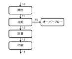
図2は、本発明に係る例示的な製造方法の概略を説明する。例示的な方法では、出発材料の混合物が、押出ステップで押し出される。これは、単軸押出機を備える押出ユニットを含みうる。原料又は材料の混合物は、押出機のバレルに供給される。バレルは加熱されてもよい。スクリューの回転が、原料を混合し、チューブの長さに沿って出口開口に向かって原料を搬送する。材料がバレルに沿って動くに従い、スクリューの回転によって生ずる摩擦によって、プロセスフローが徐々に混合し、溶融する。 FIG. 2 schematically illustrates an exemplary manufacturing method according to the present invention. In an exemplary method, a mixture of starting materials is extruded in an extrusion step. This may include an extrusion unit with a single screw extruder. The raw material or mixture of materials is fed into the barrel of the extruder. The barrel may be heated. Rotation of the screw mixes the ingredients and conveys them along the length of the tube toward the outlet opening. As the material moves along the barrel, friction caused by the rotation of the screw gradually mixes and melts the process flow.
押出機の出口流れは、一般に一定の体積の流れであることを理解することが重要である。同様に、押出機の操作中、バレルの壁とスクリューとの間の空間は、一般にプロセス流れでは完全に満たされておらず、一部の空間は利用可能なままであることを理解することも重要である。例えば、一時的な遮断で生ずる出口流れの遮断は、バレル内の圧力上昇につながる。バレルの端では、出発材料の溶融混合物が出口開口から流れ出す。一旦、定常状態の操作に達すると、出発材料の溶融流れの組成は、原料出発材料の供給比に依存する。例えば、もし供給比が変わると、新しい定常状態に達するまで長時間が必要となる可能性がある。 It is important to understand that the exit stream of an extruder is generally a constant volume stream. Similarly, it is also understood that during extruder operation, the space between the barrel wall and the screw is generally not completely filled with process flow, and some space remains available. is important. For example, a blockage of the outlet flow caused by a temporary blockage leads to an increase in pressure within the barrel. At the end of the barrel, the molten mixture of starting materials flows out of the outlet opening. Once steady state operation is reached, the composition of the starting material melt stream depends on the raw starting material feed ratio. For example, if the feed ratio changes, it may take a long time to reach a new steady state.
押出後、本発明に係る方法は、分配プロセスを含む。バレルの出口開口から、材料の溶融混合物は、分配部材へと運ばれる。この分配部材は、流入する流れの一部を、プリントヘッドへの押出成形物を調整された供給に適する計量ポンプへ分配するために好適である。プリントヘッドに提供されない押出流れの残りは、オーバーフロー出口へ向けられる。押出流れの非使用部分をオーバーフロー出口へと移動させることによって、押出機内の圧力上昇が避けられ、チューブ内での材料の滞留時間が変化せず維持される。これは、押出プロセスでの乱れを防ぐのに役立ち、従って、定常状態に達した後、押出機の一定の流出を維持することに役立つ。分配部材は、押出流れを完全にオーバーフロー出口に向けるためにも使用することができる。これは、例えば、印刷プロセスが停止した場合、又は押出機が定常状態条件下で動作していない場合に有用である。分配部材は、三方圧力弁、又は上記の目的に適した任意の他の種類のバルブであることができる。 After extrusion, the method according to the invention includes a distribution process. From the outlet opening of the barrel, the molten mixture of materials is conveyed to the distribution member. This distribution member is suitable for distributing a portion of the incoming flow to a metering pump suitable for a regulated supply of extrudate to the print head. The remainder of the extrusion flow not provided to the printhead is directed to an overflow outlet. By moving the unused portion of the extrusion flow to the overflow outlet, pressure build-up within the extruder is avoided and the residence time of the material within the tube remains unchanged. This helps prevent turbulence in the extrusion process and thus helps maintain a constant outflow of the extruder after steady state is reached. The distribution member can also be used to direct the extrusion flow completely to the overflow outlet. This is useful, for example, if the printing process is stopped or the extruder is not operating under steady state conditions. The distribution member can be a three-way pressure valve or any other type of valve suitable for the above purpose.
オーバーフロー出口は、廃棄出口に接続され、品質管理のようなサンプリング目的のために、サンプリングポートに更に接続されてもよい。任意に、温度に敏感ではない成分を使用する場合、オーバーフロー出口は、押出機にフィードバックされ得る。これは、材料の損失を低減する。熱に敏感な活性医薬成分を使用する場合、材料の損失は、流れを更なる押出サイクルへ曝すことを引き起こすリサイクルよりも好ましい。そのような場合、オーバーフロー出口は、一般に廃棄出口へ接続される。 The overflow outlet is connected to a waste outlet and may be further connected to a sampling port for sampling purposes such as quality control. Optionally, when using components that are not temperature sensitive, the overflow outlet can be fed back to the extruder. This reduces material loss. When using heat sensitive active pharmaceutical ingredients, loss of material is preferable to recycling which would cause subjecting the stream to further extrusion cycles. In such cases, the overflow outlet is generally connected to a waste outlet.
印刷プロセスに必要な流れの一部は、計量ポンプの入口に供給される。このポンプは、印刷される材料の流量を制御するのに適した任意の種類のポンプであり得る。この計量ポンプは、許容可能な速さでの3D印刷に求められる機敏な方法で、プリントヘッドへの流れを自由に開始する及び停止するために使用されてもよい。例えば、最初の印刷シーケンスの終了と第2の印刷シーケンスの開始とを可能とする、又は出力を微妙に変更して、より正確な3D印刷構造を作成する。この変更は、印刷プロセスのタイムスケールと互換性があるために十分な速さである必要がある。 A portion of the flow required for the printing process is supplied to the inlet of the metering pump. This pump can be any type of pump suitable for controlling the flow rate of the material being printed. This metering pump may be used to freely start and stop flow to the printhead in the agile manner required for 3D printing at acceptable speeds. For example, it is possible to end a first printing sequence and start a second printing sequence, or to subtly change the output to create a more accurate 3D printed structure. This change needs to be fast enough to be compatible with the timescale of the printing process.
計量ポンプから、材料の溶融混合物が、印刷ユニットへ向けられる。これは、計量ポンプから受け取られた流れから計量される方法での製品の3D印刷に適した1つ以上のノズルを備えるプリントヘッドであり得る。 From the metering pump, the molten mixture of materials is directed to the printing unit. This may be a printhead comprising one or more nozzles suitable for 3D printing of products in a metered manner from the flow received from a metering pump.
任意に、プリントヘッド内の個々のノズル又はノズルのセットは、更に計量ユニットを備えてもよい。これにより、ノズルからの流出をより正確に制御することができる。オーガーポンプは、材料が回転するスクリューによって移動するポンプである。アルキメデスタイプのスクリューは、オーガーポンプの好適なタイプを形成する。代わりに、ロータが回転する時に流体がポンプを介して、一連の小さな固定形状の個別のキャビティを介して移動する点に特徴があるプログレッシブポンプも好適である。 Optionally, individual nozzles or sets of nozzles within the printhead may further include a metering unit. This allows for more accurate control of outflow from the nozzle. An auger pump is a pump in which material is moved by a rotating screw. Archimedes type screws form the preferred type of auger pump. Alternatively, progressive pumps are also suitable, characterized in that as the rotor rotates, fluid moves through the pump through a series of small fixed-shaped individual cavities.
システム内で材料の溶融流れの固化を避けるため、印刷される材料に接触する装置の全ての部分は、好適な温度に維持されてもよい。 To avoid solidification of the molten stream of material within the system, all parts of the apparatus that come into contact with the material to be printed may be maintained at a suitable temperature.
(図の詳細な説明)
本発明に係る医薬製品を製造する例示的な製造方法、又は医薬製品の製造装置が視覚化されたステージは、例示的なプロセス又は実施形態に限られず、これらの例で使用されている材料にも限定されないことが理解される。例えば更なるステップを含む他の製造方法、又は他の材料を使用する製品、同様にそのようなステップのために好適な部品又は部品を備える装置も想定される。(Detailed explanation of the figure)
The exemplary manufacturing method for manufacturing a pharmaceutical product according to the present invention, or the stages at which the pharmaceutical product manufacturing apparatus is visualized, is not limited to the exemplary process or embodiment, and may be based on the materials used in these examples. It is understood that there is no limitation. Other manufacturing methods, eg including further steps, or products using other materials, as well as devices comprising parts or components suitable for such steps, are also envisaged.
図1は、特許文献1の教示に係るFDM装置を示す。装置は、ノズル1を備えるプリントヘッド2であって、そこから材料が印刷されるプリントヘッド2と、1つのスクリューを備えるバレルを有する押出ユニット3と、印刷される材料を押出機に供給するホッパー4と、を備える。特許文献1に記載の装置では、材料の溶融流れは、材料がそこから堆積されるプリントヘッドへ押出機から直接供給される。分配ユニットがない場合は、押出機の完全な出力ストリームがプリントヘッドへ向けられる。計量ユニットもない場合は、このストリームの流れは、調整されず、押出機からの出口流における流速及び又は組成の変動は、プリントユニットに向けられる。反対に、プリントヘッドによる堆積速度の変動は、押出機に伝わる。例えば、プリントヘッドからの中断する出力流れは、押出機内の圧力上昇をもたらし、印刷される材料の組成変動につながる処理条件の乱れを引き起こす。 FIG. 1 shows an FDM device according to the teachings of Patent Document 1. The device comprises a printhead 2 with a nozzle 1 from which the material is printed, an
図2は、本発明の態様に係る製造方法の例示的な概略図を示す。この方法では、印刷される材料の混合物は、押出ユニット10に供給される。医薬製品の製造のため、混合物は、賦形剤と活性医薬成分との混合物を含む。食品原料のような他の成分も使用することができる。押出ユニットにおいて、出発物質の混合物は、混合され、溶融される。押出機を出る溶融流れ11は、分配ユニットへと供給される。このユニットは、押出機からの押出成形物の出力流れを、プリントヘッドへの押出成形物の調整された供給に適する計量ポンプに向けられる入力流れ12に分配するように適切に選択される。プリントヘッドに提供されない押出機からの一定の出力流れの一部は、オーバーフロー出口へ向かう残余流れ15へと分配される。 FIG. 2 shows an exemplary schematic diagram of a manufacturing method according to an aspect of the invention. In this method, a mixture of materials to be printed is fed to an
プリントヘッドへの押出成形物の調整された供給のために適した計量ポンプは、前記プリントヘッドへの流れ13を提供し、プリントヘッドからは流れ14が排出され、所望の製品を形成する。オーバーフロー出口に接続された分配ユニットを含む方法を提供することで、印刷プロセスで使用されない流れの一部を、廃棄出口に向けさせることができる。これは、押出ユニット内の圧力上昇を防ぎ、前記押出機の安定した状態の出力の維持を容易とする。押出出力流れの未使用部分を廃棄出口に向けることにより、押出機内の成分の一定の滞留時間を維持することも容易となる。この方法では、押出プロセス中、一定の熱負荷が材料へ提供される。上述した両方の効果は、製造された製品の一定の組成と品質を維持することに役立つ。 A metering pump suitable for regulated feeding of the extrudate to the printhead provides a
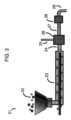
図3は、賦形剤と活性医薬成分との混合物22によって製造される医薬製品を製造するための装置21の第1の例示的な実施形態を概略的に示す。例示的な装置は、1つのスクリューが設けられたバレルを備える押出機装置23を備える。例示的な押出機は、一定の流れで押出成形物として押し出すための、所定の比率の賦形剤及び活性医薬成分の粉末又はペレット材料の混合物を受け取るために適している。出口開口から、押出成形物24は、押出機装置と計量ポンプ28との間に設けられた分配部材26の入口に供給される。分配装置は、押出機からの、印刷プロセス27で必要な押出成形物の一定の出力流れの一部を計量ポンプ28の入力へ分配するために適している。残余流れ25、つまり、プリントヘッドに提供されない押出機からの一定の出力流の一部を、オーバーフロー出口へ向ける。第1の例示的な実施形態において、図3に示すように、分配部材は、三方圧力弁を備える。 FIG. 3 schematically depicts a first exemplary embodiment of a
印刷プロセスに必要な流れは、プリントヘッド29への押出成形物の調整された供給に適した計量ポンプの入口に供給される。例示的な実施形態では、計量ポンプによって受け取られた流れから計量される方法で製品の3D印刷に適した、1つのノズルを含むプリントヘッドを示す。それぞれが1つ以上のノズルを有する複数のノズルを備えるプリントヘッド、又は代わりに複数のプリントヘッドも想定されることが理解される。同様に、食品原料のような他の成分から製品が形成されることも想定されることが理解される。 The flow required for the printing process is fed to the inlet of a metering pump suitable for the regulated feeding of extrudate to the
図4は、賦形剤及び活性医薬成分の混合物32によって製造される医薬製品を製造する装置31の第2の例示的な実施形態を概略的に示す。例示的な装置は、1つのスクリューが設けられたバレルを備える押出機装置33を備える。例示的な押出機は、押出成形物として一定の流れで押し出すための所定の比率の賦形剤と活性医薬成分との粉末又はペレット材料の混合物を受け取るために適している。押出成形物34は、出口開口から、押出機装置とプリントヘッド38の入口との間に設けられた分配部材36の入口に供給される。分配装置は、印刷プロセスで必要となる押出機からの押出成形物の一定の出力流れの一部37を、プリントヘッドの入口に分配するために適している。残余流れ35、つまり、プリントヘッドに提供されない押出機からの一定の出力流の一部は、オーバーフロー出口へと向けられる。 FIG. 4 schematically depicts a second exemplary embodiment of a
第2の例示的な実施形態において、分配部材は、三方圧力弁を備える。任意に、容積及び可動ピストンを含む部材のような圧力調整部材を、分配部材とプリントヘッドとの間に設けてもよい。例示的な第2の実施形態において、装置には2つのプリントヘッド38が設けられ、各ヘッドは、計量ポンプ39によって供給される2つのノズルを備え、ノズルは、圧力調整部材から受け取られた流れから計量される方法での製品の3D印刷に適している。本発明に係る第2の例示的な実施形態において、各ノズルは、個別の計量ポンプを備える。これは、例えば各ノズルの固有の必要性に対して材料の流れを調整する及び適合させることができるという追加の利点を有する。そのような流れを計量するために好適な任意のポンプを使用することができる。好適なポンプは、例えば、ギアポンプ、又はオージェポンプ若しくはプログレッシブキャビティポンプのようなアルキメデスタイプのスクリューポンプを含む。 In a second exemplary embodiment, the distribution member comprises a three-way pressure valve. Optionally, a pressure regulating member, such as a member containing a volume and a movable piston, may be provided between the distribution member and the printhead. In a second exemplary embodiment, the apparatus is provided with two
印刷プロセス中、押出機からの出力流れは、好ましくは、このプロセス中に計量ポンプによって要求される、例えば向けられる流れより大きいことが理解される。残余流れは、もしあれば、廃棄出口へと向けられてもよい。計量ポンプ流れへ向かう流れより多い、押出機からの出力流れを有することは、印刷プロセスにおける乱れを、例えば、材料の堆積の一時的な停止を回避することに貢献し得る。 It will be appreciated that during the printing process the output flow from the extruder is preferably greater than the flow required, eg directed, by the metering pump during this process. The residual flow, if any, may be directed to a waste outlet. Having more output flow from the extruder than flow toward the metering pump flow may contribute to avoiding disturbances in the printing process, such as temporary cessation of material deposition.
異なる数のプリントヘッド及び又は異なる数のノズルを備えるプリントヘッドを備える実施形態、又は単一の計量ポンプから流れが供給される複数のノズルを備えるプリントヘッド、並びに他の圧力調整部材を備える実施形態も想定されることが理解される。 Embodiments with printheads with different numbers of printheads and/or different numbers of nozzles, or embodiments with printheads with multiple nozzles supplied with flow from a single metering pump, as well as other pressure regulating members. It is understood that this is also assumed.
同様に、食品原料などの他の材料から形成された製品も同様に想定されることが理解されるだろう。 It will be appreciated that products formed from other materials, such as food ingredients, are likewise contemplated.
[付記]
[付記1]
押出成形物として一定の流れで押し出すための押出機装置によって賦形剤と活性医薬成分(API)とを所定の比率で含む粉末又はペレット材料の混合物を受け取ること、
前記押出機からの前記押出成形物の一定の出力流れを、プリントヘッドへの前記押出成形物の調整された供給に適した計量ポンプへ向かう入力流れへ分配すること、
前記計量ポンプにより受け取られた前記流れから計量される方法で、製品の3D印刷に適した1つ以上のノズルを備えるプリントヘッドによって前記製品を印刷すること、及び、
前記プリントヘッドへ供給されてない、前記押出機からの前記一定の出力流れの一部を、オーバーフロー出口へ向かう残余流れへ分配すること、
を含む、
賦形剤と活性医薬成分との混合物によって製造される医薬製品を製造する方法。[Additional notes]
[Additional note 1]
receiving a mixture of powder or pellet material containing excipients and an active pharmaceutical ingredient (API) in a predetermined ratio by an extruder device for extrusion in a constant flow as an extrudate;
distributing a constant output flow of the extrudate from the extruder into an input flow towards a metering pump suitable for regulated feeding of the extrudate to a printhead;
printing the product in a metered manner from the flow received by the metering pump by a printhead comprising one or more nozzles suitable for 3D printing of the product; and
distributing a portion of the constant output stream from the extruder that is not being fed to the printhead into a residual stream directed to an overflow outlet;
including,
A method of manufacturing a pharmaceutical product produced by a mixture of excipients and active pharmaceutical ingredients.
[付記2]
前記押出成形物の流れは、前記残余流れの品質管理パラメータに応じて中断される、
ことを特徴とする付記1に記載の方法、[Additional note 2]
the extrudate flow is interrupted according to quality control parameters of the residual flow;
The method according to appendix 1, characterized in that
[付記3]
前記残余流れは、少なくとも部分的に廃棄へ分配される、
ことを特徴とする付記1に記載の方法、[Additional note 3]
the residual stream is at least partially distributed to waste;
The method according to appendix 1, characterized in that
[付記4]
前記APIは、熱に敏感なAPIを含む、
ことを特徴とする付記1に記載の方法。[Additional note 4]
the API includes a heat sensitive API;
The method according to appendix 1, characterized in that:
[付記5]
賦形剤と活性医薬成分との混合物から製造される医薬製品を製造するための装置であって、
押出成形物として一定の流れで押し出すための、所定の比率の賦形剤と活性医薬成分の粉末又はペレット材料の混合物を受け取るために適した押出機装置、
計量ポンプによって受け取られた前記流れから計量される方法での前記製品の3D印刷に適した1つ以上のノズルを備えるプリントヘッド、
前記押出機装置の出口と前記プリントヘッドの入口との間に設けられた計量ポンプであって、前記プリントヘッドへの前記押出成形物の調整された供給に適した計量ポンプ、及び、
前記押出機装置と前記計量ポンプとの間に設けられた分配部材、
を備え、
前記分配部材は、
i)前記押出機装置の前記出口に接続された入口、
ii)オーバーフロー出口へ向かう出口、及び、
iii)前記計量ポンプの入口へ向かう出口、
を備え、
前記分配部材は、前記プリントヘッドへ供給されていない前記押出機からの前記一定の出力流れを、前記オーバーフロー出口へ向かう残余流れに分配することに適し、前記押出機からの前記押出成形物の前記一定の流れを、前記計量ポンプの前記入口に分配する、
装置。[Additional note 5]
An apparatus for producing a pharmaceutical product made from a mixture of excipients and an active pharmaceutical ingredient, comprising:
an extruder apparatus suitable for receiving a mixture of excipient and active pharmaceutical ingredient powder or pellet material in a predetermined ratio for extrusion in a constant flow as an extrudate;
a printhead comprising one or more nozzles suitable for 3D printing the product in a metered manner from the flow received by a metering pump;
a metering pump provided between the outlet of the extruder device and the inlet of the printhead, the metering pump being suitable for the regulated feeding of the extrudate to the printhead; and
a distribution member provided between the extruder device and the metering pump;
Equipped with
The distribution member is
i) an inlet connected to the outlet of the extruder device;
ii) an outlet towards an overflow outlet; and
iii) an outlet towards the inlet of said metering pump;
Equipped with
The distribution member is adapted to distribute the constant output flow from the extruder that is not being fed to the print head into a residual flow directed to the overflow outlet, and the distribution member distributing a constant flow to the inlet of the metering pump;
Device.
[付記6]
前記分配部材は、自動的に、前記押出機からの前記一定の出力流れを、前記計量ポンプへ向かう入力流れと前記オーバーフロー出口へ向かう残余流れとへ分配する三方圧力弁を含む、
ことを特徴とする付記5に記載の装置。[Additional note 6]
The distribution member includes a three-way pressure valve that automatically distributes the constant output flow from the extruder into an input flow toward the metering pump and a residual flow toward the overflow outlet.
The device according to appendix 5, characterized in that:
[付記7]
前記オーバーフロー出口を通る前記残余流れは、少なくとも部分的に廃棄出口へ分配される、
ことを特徴とする付記6に記載の装置。[Additional note 7]
the residual flow through the overflow outlet is at least partially distributed to a waste outlet;
The device according to appendix 6, characterized in that:
[付記8]
前記オーバーフロー出口を通る前記残余流れは、少なくとも部分的に、品質管理目的のサンプリングに適したサンプリングポートへと分配される、
ことを特徴とする付記6に記載の装置。[Additional note 8]
the residual flow through the overflow outlet is at least partially distributed to a sampling port suitable for sampling for quality control purposes;
The device according to appendix 6, characterized in that:
[付記9]
前記計量ポンプは、ギアポンプである、
ことを特徴とする付記5に記載の装置。[Additional note 9]
the metering pump is a gear pump;
The device according to appendix 5, characterized in that:
[付記10]
前記計量ポンプは、オージェポンプである、
ことを特徴とする付記5乃至8のいずれか1つに記載の装置。[Additional note 10]
the metering pump is an Auger pump;
9. The device according to any one of appendices 5 to 8, characterized in that:
[付記11]
前記オージェポンプは、アルキメデスタイプスクリューポンプまたはプログレッシブキャビティポンプである、
ことを特徴とする付記10に記載の装置。[Additional note 11]
The Auger pump is an Archimedes type screw pump or a progressive cavity pump.
The device according to
Claims (11)
Translated fromJapanese前記押出機からの前記押出成形物の一定の出力流れを、熱溶解積層法(FDM)プリントヘッドへの前記押出成形物の調整された供給に適した計量ポンプに向かわせること、
前記計量ポンプにより受け取った前記流れを用いて、製品の3D印刷に適した1つ以上のノズルを備える前記プリントヘッドによって熱溶解積層法で前記製品を形成すること、及び、
前記押出機と前記計量ポンプとの間に設けられた分配部材によって、前記押出機からの前記一定の出力流れのうち前記プリントヘッドに必要ではない残余を、オーバーフロー出口へ向かう残余流れへ分配すること、
を含む、
賦形剤と活性医薬成分との混合物によって製造される医薬製品を製造する方法。receiving a mixture of powder or pellet material containing excipients and an active pharmaceutical ingredient (API) in a predetermined ratio by an extruder device for extrusion in a constant flow as an extrudate;
directing a constant output flow of the extrudate from the extruderto a metering pump suitable for regulated feeding of the extrudate toa fused deposition modeling (FDM) printhead;
forming the product by fuseddeposition modelingusing the flowreceived by the metering pump bythe printhead comprising one or more nozzles suitable for 3D printing of the product;
a distribution member disposed between the extruder and the metering pump to distributethe remainder of the constant output flow from the extruder not required by the printhead into a remainder flow directed to an overflow outlet; ,
including,
A method of manufacturing a pharmaceutical product produced by a mixture of excipients and active pharmaceutical ingredients.
前記押出機から前記計量ポンプに向かう前記押出成形物の流れは、前記残余流れの前記品質管理に応じて中断される、
ことを特徴とする請求項1に記載の方法。the overflow outlet is connected to a sampling port for quality control;
the flow of extrudatefrom the extruder to the metering pump is interrupted in responseto the quality control of theresidual flow;
The method according to claim 1, characterized in that:
ことを特徴とする請求項1に記載の方法。the residual stream is at least partially distributed to waste;
The method according to claim 1, characterized in that:
ことを特徴とする請求項1に記載の方法。the APIis exposed toa constant thermal load;
The method according to claim 1, characterized in that:
押出成形物として一定の流れで押し出すための、所定の比率の賦形剤と活性医薬成分の粉末又はペレット材料の混合物を受け取るために適した押出機装置、
計量ポンプによって受け取られた前記流れから計量される方法での前記製品の3D印刷に適した1つ以上のノズルを備えるプリントヘッド、
前記押出機装置の出口と前記プリントヘッドの入口との間に設けられた計量ポンプであって、前記プリントヘッドへの前記押出成形物の調整された供給に適した計量ポンプ、及び、
前記押出機装置と前記計量ポンプとの間に設けられた分配部材、
を備え、
前記分配部材は、
i)前記押出機装置の前記出口に接続された入口、
ii)オーバーフロー出口へ向かう出口、及び、
iii)前記計量ポンプの入口へ向かう出口、
を備え、
前記分配部材は、前記プリントヘッドへ供給されていない前記押出機からの前記一定の出力流れを、前記オーバーフロー出口へ向かう残余流れに分配することに適し、前記押出機からの前記押出成形物の前記一定の流れを、前記計量ポンプの前記入口に分配する、
装置。An apparatus for producing a pharmaceutical product made from a mixture of excipients and an active pharmaceutical ingredient, comprising:
an extruder apparatus suitable for receiving a mixture of excipient and active pharmaceutical ingredient powder or pellet material in a predetermined ratio for extrusion in a constant flow as an extrudate;
a printhead comprising one or more nozzles suitable for 3D printing the product in a metered manner from the flow received by a metering pump;
a metering pump provided between the outlet of the extruder device and the inlet of the printhead, the metering pump being suitable for the regulated feeding of the extrudate to the printhead; and
a distribution member provided between the extruder device and the metering pump;
Equipped with
The distribution member is
i) an inlet connected to the outlet of the extruder device;
ii) an outlet towards an overflow outlet; and
iii) an outlet towards the inlet of said metering pump;
Equipped with
The distribution member is adapted to distribute the constant output flow from the extruder that is not being fed to the print head into a residual flow directed to the overflow outlet, and the distribution member distributing a constant flow to the inlet of the metering pump;
Device.
ことを特徴とする請求項5に記載の装置。The distribution member includes a three-way pressure valve that automatically distributes the constant output flow from the extruder into an input flow toward the metering pump and a residual flow toward the overflow outlet.
6. The device according to claim 5, characterized in that:
ことを特徴とする請求項6に記載の装置。the residual flow through the overflow outlet is at least partially distributed to a waste outlet;
7. The device according to claim 6.
ことを特徴とする請求項6に記載の装置。the residual flow through the overflow outlet is at least partially distributed to a sampling port suitable for sampling for quality control purposes;
7. The device according to claim 6.
ことを特徴とする請求項5に記載の装置。the metering pump is a gear pump;
6. The device according to claim 5, characterized in that:
ことを特徴とする請求項5乃至8のいずれか1項に記載の装置。the metering pump is an Auger pump;
9. Device according to any one of claims 5 to 8, characterized in that:
ことを特徴とする請求項10に記載の装置。The Auger pump is an Archimedes type screw pump or a progressive cavity pump.
11. The device according to claim 10.
Applications Claiming Priority (3)
| Application Number | Priority Date | Filing Date | Title |
|---|---|---|---|
| EP18182170.3AEP3590501A1 (en) | 2018-07-06 | 2018-07-06 | Manufacturing process and system for manufacturing a 3d printed drug delivery product |
| EP18182170.3 | 2018-07-06 | ||
| PCT/NL2019/050422WO2020009583A1 (en) | 2018-07-06 | 2019-07-05 | Manufacturing process and system for manufacturing a 3d printed drug delivery product |
Publications (2)
| Publication Number | Publication Date |
|---|---|
| JP2021529209A JP2021529209A (en) | 2021-10-28 |
| JP7403522B2true JP7403522B2 (en) | 2023-12-22 |
Family
ID=62874757
Family Applications (1)
| Application Number | Title | Priority Date | Filing Date |
|---|---|---|---|
| JP2021500153AActiveJP7403522B2 (en) | 2018-07-06 | 2019-07-05 | Manufacturing processes and systems for manufacturing 3D printed drug delivery products |
Country Status (4)
| Country | Link |
|---|---|
| US (2) | US20210267904A1 (en) |
| EP (2) | EP3590501A1 (en) |
| JP (1) | JP7403522B2 (en) |
| WO (1) | WO2020009583A1 (en) |
Families Citing this family (4)
| Publication number | Priority date | Publication date | Assignee | Title |
|---|---|---|---|---|
| EP3902405A1 (en)* | 2018-12-27 | 2021-11-03 | Kraft Foods Schweiz Holding GmbH | Method and apparatus for 3d printing and products obtained therefrom |
| GB202001747D0 (en)* | 2020-02-10 | 2020-03-25 | Fabrx Ltd | Apparatus and method for 3d printing |
| AU2021358025A1 (en)* | 2020-10-05 | 2023-03-30 | Frito-Lay North America, Inc. | Commercial scale 3D food printing |
| WO2024092237A1 (en)* | 2022-10-28 | 2024-05-02 | Board Of Regents, The University Of Texas System | Continuous mid-air 3-dimensional printing for pharmaceutical dosage forms |
Citations (6)
| Publication number | Priority date | Publication date | Assignee | Title |
|---|---|---|---|---|
| JP2011245790A (en) | 2010-05-28 | 2011-12-08 | Kohei Sawa | Kneading extrusion apparatus |
| JP2013252643A (en) | 2012-06-06 | 2013-12-19 | Olympus Corp | Kneading extrusion molding apparatus |
| CN104742375A (en) | 2015-04-02 | 2015-07-01 | 共享装备有限公司 | 3D printing equipment based on FDM |
| US20170251713A1 (en) | 2016-03-07 | 2017-09-07 | Telamens, Inc. | 3d printer and method for printing an object using a curable liquid |
| WO2017175792A1 (en) | 2016-04-06 | 2017-10-12 | アステラス製薬株式会社 | Fast-eluting three-dimensional molding, filament for fast-eluting three-dimensional molding, and material for fast-eluting three-dimensional molding |
| JP2018502878A (en) | 2015-01-21 | 2018-02-01 | バイエル・オサケユキテュアBayer Oy | Drug delivery system comprising non-steroidal anti-inflammatory drug (NSAID) and progestogen compound and method for manufacturing |
Family Cites Families (11)
| Publication number | Priority date | Publication date | Assignee | Title |
|---|---|---|---|---|
| DE2306834C2 (en)* | 1973-02-12 | 1982-07-08 | Windmöller & Hölscher, 4540 Lengerich | Film die head for the production of tubular films |
| FR2789622B1 (en)* | 1999-02-11 | 2001-06-08 | Ecia Equip Composants Ind Auto | INSTALLATION FOR MANUFACTURING THERMOPLASTIC STRUCTURAL PARTS, PARTICULARLY FOR MOTOR VEHICLES |
| ES2403187T3 (en)* | 2005-03-17 | 2013-05-16 | Sulzer Chemtech Ag | Procedure and installation for the continuous manufacture of plastic granules that can be expanded |
| FR2932956B1 (en)* | 2008-06-25 | 2010-08-27 | Air Liquide | PROCESS FOR FORMING A FOOD PRODUCT BY CRYOEXTRUSION USING PREDICTIVE TEMPERATURE REGULATION |
| US9381154B2 (en)* | 2011-06-09 | 2016-07-05 | Xerox Corporation | Direct inkjet fabrication of drug delivery devices |
| DE102012000988B3 (en) | 2012-01-20 | 2012-12-13 | Voith Patent Gmbh | Device for detecting abrasive wear |
| CA2852545A1 (en)* | 2014-05-20 | 2015-11-20 | Manfred A. A. Lupke | Material standard testing for extrusion of plastic |
| CN106515005B (en)* | 2015-09-10 | 2020-04-28 | 深圳市人彩科技有限公司 | Precision mixing type stacking forming method and assembly and color FDM-3D printer |
| CA3029869A1 (en)* | 2016-07-06 | 2018-01-11 | Grunenthal Gmbh | Reinforced pharmaceutical dosage form |
| AU2018267821B2 (en)* | 2017-05-16 | 2023-01-12 | Triastek, Inc. | 3D printing device and method |
| US20190168300A1 (en)* | 2017-05-25 | 2019-06-06 | Daniel Gelbart | Method for Making Metal Objects by 3D Printing |
- 2018
- 2018-07-06EPEP18182170.3Apatent/EP3590501A1/ennot_activeWithdrawn
- 2019
- 2019-07-05JPJP2021500153Apatent/JP7403522B2/enactiveActive
- 2019-07-05WOPCT/NL2019/050422patent/WO2020009583A1/ennot_activeCeased
- 2019-07-05USUS17/257,409patent/US20210267904A1/ennot_activeAbandoned
- 2019-07-05EPEP19749839.7Apatent/EP3817905B1/enactiveActive
- 2022
- 2022-11-23USUS17/993,197patent/US20230091824A1/ennot_activeAbandoned
Patent Citations (6)
| Publication number | Priority date | Publication date | Assignee | Title |
|---|---|---|---|---|
| JP2011245790A (en) | 2010-05-28 | 2011-12-08 | Kohei Sawa | Kneading extrusion apparatus |
| JP2013252643A (en) | 2012-06-06 | 2013-12-19 | Olympus Corp | Kneading extrusion molding apparatus |
| JP2018502878A (en) | 2015-01-21 | 2018-02-01 | バイエル・オサケユキテュアBayer Oy | Drug delivery system comprising non-steroidal anti-inflammatory drug (NSAID) and progestogen compound and method for manufacturing |
| CN104742375A (en) | 2015-04-02 | 2015-07-01 | 共享装备有限公司 | 3D printing equipment based on FDM |
| US20170251713A1 (en) | 2016-03-07 | 2017-09-07 | Telamens, Inc. | 3d printer and method for printing an object using a curable liquid |
| WO2017175792A1 (en) | 2016-04-06 | 2017-10-12 | アステラス製薬株式会社 | Fast-eluting three-dimensional molding, filament for fast-eluting three-dimensional molding, and material for fast-eluting three-dimensional molding |
Also Published As
| Publication number | Publication date |
|---|---|
| EP3590501A1 (en) | 2020-01-08 |
| EP3817905B1 (en) | 2024-04-03 |
| EP3817905C0 (en) | 2024-04-03 |
| WO2020009583A1 (en) | 2020-01-09 |
| EP3817905A1 (en) | 2021-05-12 |
| JP2021529209A (en) | 2021-10-28 |
| US20210267904A1 (en) | 2021-09-02 |
| US20230091824A1 (en) | 2023-03-23 |
Similar Documents
| Publication | Publication Date | Title |
|---|---|---|
| JP7403522B2 (en) | Manufacturing processes and systems for manufacturing 3D printed drug delivery products | |
| TWI786444B (en) | Extruding system and method of extruding | |
| EP2578378B1 (en) | Kneading extruder | |
| US20160096321A1 (en) | Apparatus for three-dimensional printing | |
| EP2735418B1 (en) | Injection molding machine and raw material metering unit | |
| US3866890A (en) | Apparatus for simultaneous plasticating and mixing | |
| TW201903014A (en) | Mixing mechanism of supercritical fluid and polymer raw material melt | |
| CN107635735B (en) | Melting apparatus and method for melting meltable plastic materials, method for mixing reactive plastic components | |
| ITMI20002383A1 (en) | CONTINUOUS MIXER | |
| CN108817395B (en) | Additive manufacturing device and method | |
| US10179429B2 (en) | Device for polymerising lactams in moulds | |
| KR102320668B1 (en) | 3D Printer Head Device and Control Method for Blended Drainage Control of Soft Foamed Polymer Materials | |
| JP7270501B2 (en) | Extrusion manufacturing device for foam molded product, extrusion manufacturing method, and screw for extrusion manufacturing device for foam molded product | |
| KR101692978B1 (en) | 3d printer that implements the fragrance material | |
| US3375552A (en) | Apparatus for forming plastic units | |
| EP3894159B1 (en) | Plant for treatment of polymeric materials | |
| US20240092018A1 (en) | Integrated Additive Manufacturing Apparatus and Method | |
| JPS5889341A (en) | Extruder for thermoplastic resin molding | |
| KR102063006B1 (en) | Screw extruder for extruding products with two or more colors | |
| CN108817396B (en) | Additive manufacturing device and method | |
| JP2812635B2 (en) | Polymer kneading method | |
| Dreiblatt | Extrusioneering International, Inc., Randolph, New Jersey, USA |
Legal Events
| Date | Code | Title | Description |
|---|---|---|---|
| A621 | Written request for application examination | Free format text:JAPANESE INTERMEDIATE CODE: A621 Effective date:20220609 | |
| A977 | Report on retrieval | Free format text:JAPANESE INTERMEDIATE CODE: A971007 Effective date:20230426 | |
| A131 | Notification of reasons for refusal | Free format text:JAPANESE INTERMEDIATE CODE: A131 Effective date:20230509 | |
| A521 | Request for written amendment filed | Free format text:JAPANESE INTERMEDIATE CODE: A523 Effective date:20230809 | |
| TRDD | Decision of grant or rejection written | ||
| A01 | Written decision to grant a patent or to grant a registration (utility model) | Free format text:JAPANESE INTERMEDIATE CODE: A01 Effective date:20231121 | |
| A61 | First payment of annual fees (during grant procedure) | Free format text:JAPANESE INTERMEDIATE CODE: A61 Effective date:20231212 | |
| R150 | Certificate of patent or registration of utility model | Ref document number:7403522 Country of ref document:JP Free format text:JAPANESE INTERMEDIATE CODE: R150 |