JP7402889B2 - Spatial multiplexed waveforms for selective cell ablation - Google Patents
Spatial multiplexed waveforms for selective cell ablationDownload PDFInfo
- Publication number
- JP7402889B2 JP7402889B2JP2021555452AJP2021555452AJP7402889B2JP 7402889 B2JP7402889 B2JP 7402889B2JP 2021555452 AJP2021555452 AJP 2021555452AJP 2021555452 AJP2021555452 AJP 2021555452AJP 7402889 B2JP7402889 B2JP 7402889B2
- Authority
- JP
- Japan
- Prior art keywords
- electrodes
- signal generator
- pulse
- monophasic
- output
- Prior art date
- Legal status (The legal status is an assumption and is not a legal conclusion. Google has not performed a legal analysis and makes no representation as to the accuracy of the status listed.)
- Active
Links
Images


Classifications
- A—HUMAN NECESSITIES
- A61—MEDICAL OR VETERINARY SCIENCE; HYGIENE
- A61B—DIAGNOSIS; SURGERY; IDENTIFICATION
- A61B18/00—Surgical instruments, devices or methods for transferring non-mechanical forms of energy to or from the body
- A61B18/04—Surgical instruments, devices or methods for transferring non-mechanical forms of energy to or from the body by heating
- A61B18/12—Surgical instruments, devices or methods for transferring non-mechanical forms of energy to or from the body by heating by passing a current through the tissue to be heated, e.g. high-frequency current
- A61B18/14—Probes or electrodes therefor
- A—HUMAN NECESSITIES
- A61—MEDICAL OR VETERINARY SCIENCE; HYGIENE
- A61B—DIAGNOSIS; SURGERY; IDENTIFICATION
- A61B18/00—Surgical instruments, devices or methods for transferring non-mechanical forms of energy to or from the body
- A61B18/04—Surgical instruments, devices or methods for transferring non-mechanical forms of energy to or from the body by heating
- A61B18/12—Surgical instruments, devices or methods for transferring non-mechanical forms of energy to or from the body by heating by passing a current through the tissue to be heated, e.g. high-frequency current
- A61B18/1206—Generators therefor
- A—HUMAN NECESSITIES
- A61—MEDICAL OR VETERINARY SCIENCE; HYGIENE
- A61B—DIAGNOSIS; SURGERY; IDENTIFICATION
- A61B18/00—Surgical instruments, devices or methods for transferring non-mechanical forms of energy to or from the body
- A61B2018/00053—Mechanical features of the instrument of device
- A61B2018/0016—Energy applicators arranged in a two- or three dimensional array
- A—HUMAN NECESSITIES
- A61—MEDICAL OR VETERINARY SCIENCE; HYGIENE
- A61B—DIAGNOSIS; SURGERY; IDENTIFICATION
- A61B18/00—Surgical instruments, devices or methods for transferring non-mechanical forms of energy to or from the body
- A61B2018/00571—Surgical instruments, devices or methods for transferring non-mechanical forms of energy to or from the body for achieving a particular surgical effect
- A61B2018/00577—Ablation
- A—HUMAN NECESSITIES
- A61—MEDICAL OR VETERINARY SCIENCE; HYGIENE
- A61B—DIAGNOSIS; SURGERY; IDENTIFICATION
- A61B18/00—Surgical instruments, devices or methods for transferring non-mechanical forms of energy to or from the body
- A61B2018/00571—Surgical instruments, devices or methods for transferring non-mechanical forms of energy to or from the body for achieving a particular surgical effect
- A61B2018/00613—Irreversible electroporation
- A—HUMAN NECESSITIES
- A61—MEDICAL OR VETERINARY SCIENCE; HYGIENE
- A61B—DIAGNOSIS; SURGERY; IDENTIFICATION
- A61B18/00—Surgical instruments, devices or methods for transferring non-mechanical forms of energy to or from the body
- A61B2018/00636—Sensing and controlling the application of energy
- A—HUMAN NECESSITIES
- A61—MEDICAL OR VETERINARY SCIENCE; HYGIENE
- A61B—DIAGNOSIS; SURGERY; IDENTIFICATION
- A61B18/00—Surgical instruments, devices or methods for transferring non-mechanical forms of energy to or from the body
- A61B2018/00636—Sensing and controlling the application of energy
- A61B2018/00696—Controlled or regulated parameters
- A61B2018/0075—Phase
- A—HUMAN NECESSITIES
- A61—MEDICAL OR VETERINARY SCIENCE; HYGIENE
- A61B—DIAGNOSIS; SURGERY; IDENTIFICATION
- A61B18/00—Surgical instruments, devices or methods for transferring non-mechanical forms of energy to or from the body
- A61B2018/00636—Sensing and controlling the application of energy
- A61B2018/00773—Sensed parameters
- A61B2018/00875—Resistance or impedance
- A—HUMAN NECESSITIES
- A61—MEDICAL OR VETERINARY SCIENCE; HYGIENE
- A61B—DIAGNOSIS; SURGERY; IDENTIFICATION
- A61B18/00—Surgical instruments, devices or methods for transferring non-mechanical forms of energy to or from the body
- A61B18/04—Surgical instruments, devices or methods for transferring non-mechanical forms of energy to or from the body by heating
- A61B18/12—Surgical instruments, devices or methods for transferring non-mechanical forms of energy to or from the body by heating by passing a current through the tissue to be heated, e.g. high-frequency current
- A61B18/1206—Generators therefor
- A61B2018/124—Generators therefor switching the output to different electrodes, e.g. sequentially
- A—HUMAN NECESSITIES
- A61—MEDICAL OR VETERINARY SCIENCE; HYGIENE
- A61B—DIAGNOSIS; SURGERY; IDENTIFICATION
- A61B18/00—Surgical instruments, devices or methods for transferring non-mechanical forms of energy to or from the body
- A61B18/04—Surgical instruments, devices or methods for transferring non-mechanical forms of energy to or from the body by heating
- A61B18/12—Surgical instruments, devices or methods for transferring non-mechanical forms of energy to or from the body by heating by passing a current through the tissue to be heated, e.g. high-frequency current
- A61B18/1206—Generators therefor
- A61B2018/1246—Generators therefor characterised by the output polarity
- A61B2018/1253—Generators therefor characterised by the output polarity monopolar
- A—HUMAN NECESSITIES
- A61—MEDICAL OR VETERINARY SCIENCE; HYGIENE
- A61B—DIAGNOSIS; SURGERY; IDENTIFICATION
- A61B18/00—Surgical instruments, devices or methods for transferring non-mechanical forms of energy to or from the body
- A61B18/04—Surgical instruments, devices or methods for transferring non-mechanical forms of energy to or from the body by heating
- A61B18/12—Surgical instruments, devices or methods for transferring non-mechanical forms of energy to or from the body by heating by passing a current through the tissue to be heated, e.g. high-frequency current
- A61B18/1206—Generators therefor
- A61B2018/1273—Generators therefor including multiple generators in one device
Landscapes
- Health & Medical Sciences (AREA)
- Surgery (AREA)
- Engineering & Computer Science (AREA)
- Life Sciences & Earth Sciences (AREA)
- Biomedical Technology (AREA)
- Molecular Biology (AREA)
- Nuclear Medicine, Radiotherapy & Molecular Imaging (AREA)
- Plasma & Fusion (AREA)
- Physics & Mathematics (AREA)
- Heart & Thoracic Surgery (AREA)
- Medical Informatics (AREA)
- Otolaryngology (AREA)
- Animal Behavior & Ethology (AREA)
- General Health & Medical Sciences (AREA)
- Public Health (AREA)
- Veterinary Medicine (AREA)
- Electrotherapy Devices (AREA)
- Surgical Instruments (AREA)
Description
Translated fromJapanese本発明は選択的細胞切除のための空間多重化波形に関する。 The present invention relates to spatially multiplexed waveforms for selective cell ablation.
病変組織の除去又は破壊は、多くの癌治療法の目標である。腫瘍は外科的に除去してもよいが、より侵襲性の低いアプローチが多くの注目を集めている。組織切除は、体内の望ましくない組織を破壊する低侵襲な方法である。切除は、熱的であってもよく、又は非熱的であってもよい。 Removal or destruction of diseased tissue is the goal of many cancer treatments. Tumors may be removed surgically, but less invasive approaches are receiving much attention. Tissue ablation is a minimally invasive method of destroying unwanted tissue within the body. Ablation may be thermal or non-thermal.
熱的切除は、望ましくない細胞を破壊するために、熱を加えるか、又は熱を除去する。たとえば、冷凍切除は、細胞外区画を凍結させることによって、-15Cで細胞の脱水を開始させ、さらに低温で膜破裂を生じさせることによって細胞を殺す。冷凍切除は、患者の抗腫瘍免疫反応を(有益に)刺激することが公知である。 Thermal ablation applies or removes heat to destroy unwanted cells. For example, cryoablation kills cells by freezing the extracellular compartment, initiating cell dehydration at -15C, and causing membrane rupture at lower temperatures. Cryoablation is known to (beneficially) stimulate anti-tumor immune responses in patients.
加熱に基づく熱切除は、組織を破壊するために加熱する。無線周波数(RF:Radio-frequency)熱切除、マイクロ波切除及び高密度焦点式超音波療法は、それぞれ、局所組織の温度を身体の正常な37℃よりもかなり上に上げるために用いることができる。たとえば、RF熱切除は、摩擦によって熱に変換される細胞膜の振動を誘発するために高周波電界を用いる。細胞温度が50℃に達すれば細胞死は30秒で起こり、より高い温度では細胞死は瞬時に起こる。しかしながら、加熱に基づく切除は、冷凍切除に伴う望ましい免疫反応を引き起こさない可能性がある。 Heat-based thermal ablation uses heat to destroy tissue. Radio-frequency (RF) thermal ablation, microwave ablation, and high-intensity focused ultrasound therapy can each be used to raise local tissue temperatures well above the body's normal 37°C. . For example, RF thermal ablation uses high frequency electric fields to induce vibrations in cell membranes that are converted into heat by friction. Cell death occurs in 30 seconds when the cell temperature reaches 50°C, and at higher temperatures cell death occurs instantaneously. However, heat-based ablation may not elicit the desired immune response associated with cryoablation.
加熱又は冷却を用いる熱切除技術は、それぞれ、治療領域の正常構造を助ける能力をほとんどあるいはまったく持たないという欠点がある。血管構造、神経構造又は他の構造への二次的な損傷は望ましくない。したがって、様々な研究者が、非熱切除も探求してきた。 Thermal ablation techniques using heating or cooling each have the disadvantage of having little or no ability to aid the normal structure of the treated area. Secondary damage to vascular, neural or other structures is undesirable. Therefore, various researchers have also explored non-thermal ablation.
非熱切除技術は、電気化学療法及び不可逆的電気穿孔を含む。電気穿孔とは、高電圧パルス電界にさらされた細胞の細胞膜が、脂質二重層の不安定化により一時的に透過性になる現象を指す。次いで、少なくとも一時的に孔が形成される。電気化学療法は、孔の形成と、細胞死をもたらす化学物質の導入とを組み合わせている。用いる化学分子が大きいため、電界を受ける細胞のみがその化学物質を吸収し、その後死ぬため、治療ゾーンに有用な選択性をもたらす。不可逆的電気穿孔(IRE:Irreversible electroporation)は、化学物質を省き、代わりに通常は振幅が大きい電界を用い、回復点を超えて細胞膜の孔を拡大させるため、利用できる細胞膜がないために細胞死を引き起こす。印加電界の空間特性は、どの細胞及び組織が影響を受けるかを制御するため、熱技術と比較して、治療ゾーンでのより優れた選択性を可能にする。 Non-thermal ablation techniques include electrochemotherapy and irreversible electroporation. Electroporation refers to a phenomenon in which the cell membrane of a cell exposed to a high-voltage pulsed electric field becomes temporarily permeable due to destabilization of the lipid bilayer. A hole is then formed, at least temporarily. Electrochemotherapy combines pore formation with the introduction of chemicals that cause cell death. Because the chemical molecules used are large, only the cells subjected to the electric field will absorb the chemical and subsequently die, providing useful selectivity to the treatment zone. Irreversible electroporation (IRE) omits chemicals and instead uses an electric field, usually of high amplitude, to enlarge the cell membrane pores beyond the point of recovery, causing cell death due to no available cell membrane. cause. The spatial characteristics of the applied electric field control which cells and tissues are affected, thus allowing greater selectivity in the treatment zone compared to thermal techniques.
電気(熱的か否かにかかわらず)切除技術を用いる場合の課題の1つは、局所筋肉刺激に関するものである。単相波形は、一定の細胞死を引き起こす点で、IREにより優れた結果をもたらすと考えられている。しかしながら、単相波形は、とりわけ筋肉刺激を引き起こす傾向にあり、手術を容易にするために麻痺薬の使用を必要とする。二相波形は、筋肉刺激を回避するが、単相波形と同じエネルギーレベル及び振幅、又は同じエネルギーレベルもしくは振幅では同等に有効ではない可能性がある。二相波形をより有効にするために、単に電力を上げることは、熱切除を引き起こすリスクがある。筋肉刺激を回避しながら、IREのための単相刺激と同等に有効な使用波形を可能にし、それによって単相治療と二相治療の両方の利点を得るための、最新技術の強化と代替手段が望まれている。 One of the challenges when using electrical (thermal or not) ablation techniques concerns local muscle stimulation. Monophasic waveforms are believed to provide better results for IRE in causing constant cell death. However, monophasic waveforms are particularly prone to causing muscle irritation and require the use of paralytic drugs to facilitate surgery. Biphasic waveforms avoid muscle stimulation, but may not be as effective at the same energy levels and amplitudes as monophasic waveforms, or at the same energy levels or amplitudes. Simply increasing the power to make the biphasic waveform more effective risks causing thermal ablation. State-of-the-art technology enhancements and alternatives to allow use of waveforms as effective as monophasic stimulation for IRE while avoiding muscle stimulation, thereby obtaining the benefits of both monophasic and biphasic treatments. is desired.
本件発明者らは、とりわけ、解決すべき課題は、筋肉刺激を避けながら、高い効果と組織選択性とを組み合わせた切除治療を提供することであると認識した。以下に示すいくつかの例は、このような目的を達成するために、治療出力の空間多重化を使用する。 The inventors have recognized that, inter alia, the problem to be solved is to provide an ablative treatment that combines high efficacy and tissue selectivity while avoiding muscle stimulation. Some examples presented below use spatial multiplexing of treatment outputs to achieve such goals.
例示であって限定するものではない第1の例は、組織切除エネルギーの送達に使用するのに適した信号発生器であって、電圧変換回路、エネルギー蓄積回路及び出力制御回路を含む治療出力ブロックと、組織切除エネルギーの送達プローブに接続するのに適した入力/出力回路であって、それに接続され、複数の電極を有するプローブを、複数の電極のサブセットの個々の活性化によって使用できるように複数の出力チャンネルを規定する入力/出力回路と、ユーザが信号発生器を制御することを可能にし、信号発生器によって送達される組織切除エネルギーの1つ以上のパラメータを表示するのに適したユーザインタフェースと、治療出力ブロックとユーザインタフェースとに接続されたコントローラと、コントローラに接続され、治療サイクルであって、少なくとも3つの電極から選択される電極の第1対間の第1単相パルスと、少なくとも3つの電極から選択される電極の第2対間の第2単相パルスと、少なくとも3つの電極から選択される電極の第3対間の第3単相パルスとを含む治療サイクルの送達のための格納された命令を有するメモリと、を含む信号発生器において、各第1、第2及び第3単相パルスが、第1、第2及び第3単相パルスのそれぞれに固有の出力チャンネルの定義を含む格納された命令を有するアノード及びカソードの固有の組み合わせを使用し、各治療サイクルの終了時に、各出力チャンネルによって送達された電荷量がゼロ付近に保たれ、格納された命令が、周辺組織の時定数未満である規定の最大時間内に治療サイクルが完了することを要求し、時定数が、筋収縮の高リスクに関連する時間の長さを規定する、信号発生器の形態を取る。 A first illustrative and non-limiting example is a signal generator suitable for use in the delivery of tissue ablation energy, the treatment output block including a voltage conversion circuit, an energy storage circuit and a power control circuit. and an input/output circuit suitable for connection to a tissue ablation energy delivery probe, the input/output circuit being connected thereto such that the probe having a plurality of electrodes can be used by individual activation of a subset of the plurality of electrodes. an input/output circuit defining a plurality of output channels and suitable for allowing the user to control the signal generator and displaying one or more parameters of the tissue ablation energy delivered by the signal generator; a controller connected to the interface, the treatment output block and the user interface; and a first monophasic pulse between the first pair of electrodes selected from the at least three electrodes in a treatment cycle, the controller being connected to the controller; delivery of a treatment cycle comprising a second monophasic pulse between a second pair of electrodes selected from the at least three electrodes and a third monophasic pulse between a third pair of electrodes selected from the at least three electrodes. a memory having stored instructions for each of the first, second and third monophasic pulses; Using a unique combination of anode and cathode with a stored instruction containing the definition of , at the end of each treatment cycle, the amount of charge delivered by each output channel is kept near zero, and the stored instruction is A form of signal generator that requires the treatment cycle to be completed within a defined maximum time that is less than the time constant of the surrounding tissue, and where the time constant defines a length of time that is associated with a high risk of muscle contraction. take.
例示であって限定するものではない第1の例に加えて、あるいはこれに代えて、格納された命令は、内部又は表面にプローブが配置される組織の電気穿孔閾値を超える第1、第2及び第3単相パルスのそれぞれの振幅を規定してもよい。 In addition to or in the alternative to the first illustrative and non-limiting example, the stored instructions may include first and second electroporation thresholds that exceed the electroporation threshold of the tissue in or on which the probe is placed. and the amplitude of each of the third single-phase pulses may be defined.
例示であって限定するものではない第1の例に加えて、あるいはこれに代えて、格納された命令は、内部又は表面にプローブが配置される組織の不可逆的電気穿孔閾値を超える第1、第2及び第3単相パルスのそれぞれの振幅を規定してもよい。 In addition to or in the alternative to the first illustrative and non-limiting example, the stored instructions may include a first step that exceeds an irreversible electroporation threshold of the tissue in or on which the probe is placed; The amplitude of each of the second and third monophasic pulses may be defined.
例示であって限定するものではない第1の例に加えて、あるいはこれに代えて、格納された命令は、プローブを考慮して、1センチメートルあたり約600ボルトを超える第1、第2及び第3単相パルスのそれぞれの振幅を規定してもよい。 In addition to or in lieu of the first illustrative and non-limiting example, the stored instructions may include the first, second, and The amplitude of each of the third monophasic pulses may be defined.
例示であって限定するものではない第1の例に加えて、あるいはこれに代えて、格納された命令は、約10マイクロ秒未満のパルス幅をそれぞれが有するように第1、第2及び第3単相パルスを規定してもよい。 In addition to or in the alternative to the first illustrative and non-limiting example, the stored instructions may include first, second and second instructions each having a pulse width of less than about 10 microseconds. Three monophasic pulses may be defined.
例示であって限定するものではない第1の例に加えて、あるいはこれに代えて、格納された命令は、筋収縮を防止するために、1ミリ秒未満の時間間隔で完了するようにパルス列を構成してもよい。 In addition to, or in lieu of, the first illustrative and non-limiting example, the stored instructions include a pulse train that completes in a time interval of less than 1 millisecond to prevent muscle contraction. may be configured.
例示であって限定するものではない第1の例に加えて、あるいはこれに代えて、格納された命令は、パルス列の最後の単相パルスが送達されるとき、すべての出力チャンネルを通じて電荷平衡が達成されるようにパルス列を構成してもよい。 In addition to, or in lieu of, the first illustrative and non-limiting example, the stored instructions may provide charge balance across all output channels when the last monophasic pulse of the pulse train is delivered. The pulse train may be configured to achieve this.
例示であって限定するものではない第1の例に加えて、あるいはこれに代えて、機器は、入力/出力回路構成に接続され、各出力チャンネルにおいて電流又は電圧の少なくとも1つを監視するのに適した検出回路構成をさらに備え、格納された命令は、電荷平衡の計算を容易にするために、治療出力時のインピーダンスを監視するための命令をさらに含んでもよい。 In addition to or in the alternative to the first illustrative and non-limiting example, the device is connected to the input/output circuitry and monitors at least one of current or voltage at each output channel. The stored instructions may further include instructions for monitoring impedance at the output of the therapy to facilitate charge balance calculations.
これに加えて、あるいはこれに代えて、格納された命令は、各出力チャンネルにおいて送達される電荷をコントローラに監視させ、パルス列の完了前に、1つ以上の単相パルスの送達を行って、切除治療送達時の電流の流れ又はインピーダンスの1つ以上の変動により普通ならゼロ以外のはずの電荷平衡を高めてもよい。 Additionally or alternatively, the stored instructions cause the controller to monitor the charge delivered on each output channel and, prior to completion of the pulse train, deliver one or more monophasic pulses; One or more variations in current flow or impedance during ablative therapy delivery may enhance the otherwise non-zero charge balance.
これに加えて、あるいはこれに代えて、格納された命令は、各出力チャンネルにおいて送達される電荷をコントローラに監視させ、パルス列の完了前に、1つ以上の治療パルスのパルス幅をコントローラに調節させて電荷の不均衡を減少させてもよい。 Additionally or alternatively, the stored instructions cause the controller to monitor the charge delivered at each output channel and cause the controller to adjust the pulse width of one or more treatment pulses prior to completion of the pulse train. may be used to reduce charge imbalance.
これに加えて、あるいはこれに代えて、格納された命令は、各出力チャンネルにおいて送達される電荷をコントローラに監視させ、パルス列の完了前に、1つ以上の治療パルスの電圧レベルをコントローラに調節させて電荷の不均衡を減少させてもよい。 Additionally or alternatively, the stored instructions cause the controller to monitor the charge delivered at each output channel and cause the controller to adjust the voltage level of one or more treatment pulses prior to completion of the pulse train. may be used to reduce charge imbalance.
例示であって限定するものではない第1の例に加えて、あるいはこれに代えて、格納された命令は、パルス列の少なくとも2回の送達を要求してもよい。
他の例は、例示であって限定するものではない第1の例に記載の信号発生器と、独立してアドレス可能な複数の電極をその表面に有するレビーン(LeVeen、登録商標)ニードルプローブとを含むシステムを含む。In addition to or in the alternative to the first illustrative and non-limiting example, the stored instructions may require delivery of the pulse train at least twice.
Other examples include the signal generator described in the first example, which is illustrative and non-limiting, and a LeVeen® needle probe having a plurality of independently addressable electrodes on its surface. Including systems that include.
他の例は、例示であって限定するものではない第1の例に記載の信号発生器と、プローブ使用時に患者の身体上に配置されるのに適したリターン電極とを含むシステムを含む。
例示であって限定するものではない第2の例は、少なくとも3つの電極を含む複数の電極を用いて組織を切除する方法であって、切除される組織の内部又は表面に少なくとも3つの電極を配置し、少なくとも3つの電極から選択される電極の第1対間の第1単相パルスと、少なくとも3つの電極から選択される電極の第2対間の第2単相パルスと、少なくとも3つの電極から選択される電極の第3対間の第3単相パルスとを含む治療サイクルを送達し、各第1、第2及び第3単相パルスは、アノードとカソードの固有の組み合わせを使用し、各治療サイクルの終了時に、各電極によって送達される電荷量はゼロ付近に保たれ、治療サイクルは、周辺組織の時定数未満である規定の最大時間内に完了し、時定数は、筋収縮の高リスクに関連する時間の長さを規定することを含む方法の形態を取る。Other examples include a system that includes the signal generator described in the first exemplary and non-limiting example and a return electrode suitable for placement on a patient's body during use of the probe.
A second illustrative and non-limiting example is a method of ablating tissue using a plurality of electrodes, including at least three electrodes, the method comprising at least three electrodes in or on the tissue to be ablated. a first monophasic pulse between a first pair of electrodes selected from the at least three electrodes; a second monophasic pulse between a second pair of electrodes selected from the at least three electrodes; a third monophasic pulse between a third pair of electrodes selected from the electrodes, each first, second and third monophasic pulse using a unique combination of anode and cathode; , at the end of each treatment cycle, the amount of charge delivered by each electrode is kept near zero, and the treatment cycle is completed within a defined maximum time that is less than the time constant of the surrounding tissue, the time constant of muscle contraction This may take the form of a method that includes specifying the length of time associated with a high risk of
例示であって限定するものではない第2の例に加えて、あるいはこれに代えて、第1、第2及び第3単相パルスは、それぞれ、電極が内部又は表面に配置される組織の電気穿孔閾値を超える振幅を有していてもよい。 In addition to, or in lieu of, the second illustrative and non-limiting example, the first, second and third monophasic pulses each represent an electrical charge in the tissue within or on which the electrode is disposed. It may have an amplitude above the perforation threshold.
例示であって限定するものではない第2の例に加えて、あるいはこれに代えて、第1、第2及び第3単相パルスは、それぞれ、電極が内部又は表面に配置される組織の不可逆的電気穿孔閾値を超える振幅を有していてもよい。 In addition to or in lieu of the second illustrative and non-limiting example, the first, second and third monophasic pulses, respectively, are irreversible in the tissue in or on which the electrode is placed. may have an amplitude above the target electroporation threshold.
例示であって限定するものではない第2の例に加えて、あるいはこれに代えて、第1、第2及び第3単相パルスは、それぞれ、1センチメートルあたり約600ボルトを上回る電界を発生させてもよい。 In addition to or in lieu of the second illustrative and non-limiting example, the first, second and third monophasic pulses each generate an electric field greater than about 600 volts per centimeter. You may let them.
例示であって限定するものではない第2の例に加えて、あるいはこれに代えて、第1、第2及び第3単相パルスは、それぞれ、約10マイクロ秒未満のパルス幅を有していてもよい。 In addition to or in the alternative to the second illustrative and non-limiting example, the first, second and third monophasic pulses each have a pulse width of less than about 10 microseconds. It's okay.
例示であって限定するものではない第2の例に加えて、あるいはこれに代えて、複数の電極の少なくとも2つは、少なくともいくつかの電極の対が、標的組織を通る治療ベクトルを規定するように、切除される標的組織の周りに配置されるのに適したコンフォーマルアレイの一部であってもよい。 In addition to or in the alternative to the second illustrative and non-limiting example, at least two of the plurality of electrodes define a treatment vector through the target tissue. As such, it may be part of a conformal array suitable for placement around the target tissue to be ablated.
これに加えて、あるいはこれに代えて、複数の電極の少なくとも4つは、標的組織領域の周りに空間的に配置されるように組織に配置されてもよく、第1、第2及び第3電極対の少なくとも1つは、それらの間で少なくとも1つの別の電極を有する2つの電極を使用する。 Additionally or alternatively, at least four of the plurality of electrodes may be disposed in the tissue so as to be spatially disposed about the target tissue area, with first, second and third electrodes being arranged spatially around the target tissue area. At least one of the electrode pairs uses two electrodes with at least one other electrode between them.
例示であって限定するものではない第2の例に加えて、あるいはこれに代えて、各パルス列は、筋収縮を防止するために、1ミリ秒未満の時間間隔で完了してもよい。
例示であって限定するものではない第2の例に加えて、あるいはこれに代えて、電荷平衡は、パルス列の最後の単相パルスが送達されるとき、すべての電極を通じて達成される。In addition to or in the alternative to the second illustrative and non-limiting example, each pulse train may be completed in time intervals of less than 1 millisecond to prevent muscle contraction.
In addition to or in the alternative to the second illustrative and non-limiting example, charge balance is achieved across all electrodes when the last monophasic pulse of the pulse train is delivered.
例示であって限定するものではない第2の例に加えて、あるいはこれに代えて、方法は、電荷平衡の計算を容易にするために、第1、第2及び第3電極対のそれぞれの間でインピーダンスを監視することをさらに含んでもよい。 In addition to, or in lieu of, the second illustrative and non-limiting example, the method provides a method for each of the first, second and third electrode pairs to facilitate charge balance calculations. The method may further include monitoring impedance between.
例示であって限定するものではない第2の例に加えて、あるいはこれに代えて、方法は、電荷平衡の計算を容易にするために、第1、第2及び第3電極対のそれぞれの間で電流の流れを監視することをさらに含んでもよい。 In addition to, or in lieu of, the second illustrative and non-limiting example, the method provides a method for each of the first, second and third electrode pairs to facilitate charge balance calculations. It may further include monitoring the flow of current between.
例示であって限定するものではない第2の例に加えて、あるいはこれに代えて、方法は、パルス列時に、複数の電極によって送達される電荷を監視させることと、パルス列の完了前に、1つ以上の単相パルスを送達して、切除治療送達時に使用される電極対間の電流の流れ又はインピーダンスの1つ以上の変動により普通ならゼロ以外のはずの電荷平衡を高めることとをさらに含んでもよい。 In addition to or in the alternative to the second illustrative and non-limiting example, the method includes monitoring charge delivered by a plurality of electrodes during a pulse train and, prior to completion of the pulse train, further comprising delivering two or more monophasic pulses to enhance charge balance that would normally be non-zero due to one or more variations in current flow or impedance between the electrode pairs used during ablation therapy delivery. But that's fine.
例示であって限定するものではない第2の例に加えて、あるいはこれに代えて、方法は、電荷の不均衡を減少させるために、1つ以上の治療パルスのパルス幅を調整することをさらに含んでもよい。 In addition to or in the alternative to the second illustrative and non-limiting example, the method includes adjusting the pulse width of one or more treatment pulses to reduce charge imbalance. It may further include.
例示であって限定するものではない第2の例に加えて、あるいはこれに代えて、方法は、電荷の不均衡を減少させるために、1つ以上の治療パルスの電圧レベルを調整することをさらに含んでもよい。 In addition to or in the alternative to the second illustrative and non-limiting example, the method includes adjusting the voltage level of one or more treatment pulses to reduce charge imbalance. It may further include.
例示であって限定するものではない第3の例は、少なくとも3つの電極を含む複数の電極を用いて組織を切除する方法であって、切除される組織の内部又は表面に少なくとも3つの電極を配置し、少なくとも3つの電極から選択される電極の第1対間の第1単相パルス、少なくとも3つの電極から選択される電極の第2対であって、第1対とは異なる第2対間の第2単相パルス、電極の第1対を用いる第1単相パルスと等しいが逆の第3単相パルス、電極の第2対を用いる第2単相パルスと等しいが逆の第4単相パルスを含み、各治療サイクルの終了時に、各電極によって送達される電荷量がゼロ付近に保たれ、第2単相パルスが、第1単相パルスと第3単相パルスとの間で行われ、第3単相パルスが、第2単相パルスと第4単相パルスとの間で行われ、治療サイクルが、周辺組織の時定数未満である規定の最大時間内に完了し、時定数が、筋収縮の高リスクに関連する時間の長さを規定する治療サイクルを送達することを含む方法の形態を取る。 A third illustrative and non-limiting example is a method of ablating tissue using a plurality of electrodes, including at least three electrodes, the method comprising at least three electrodes in or on the tissue to be ablated. a first monophasic pulse between a first pair of electrodes selected from the at least three electrodes; a second pair of electrodes selected from the at least three electrodes, the second pair being different from the first pair; a second monophasic pulse between, a third monophasic pulse equal to but opposite to the first monophasic pulse using the first pair of electrodes, a fourth monophasic pulse equal to but opposite to the second monophasic pulse using the second pair of electrodes; a monophasic pulse, at the end of each treatment cycle, the amount of charge delivered by each electrode is maintained near zero, and a second monophasic pulse is applied between the first monophasic pulse and the third monophasic pulse. a third monophasic pulse is delivered between the second monophasic pulse and a fourth monophasic pulse, and the treatment cycle is completed within a predetermined maximum time that is less than the time constant of the surrounding tissue; The constant takes the form of a method that includes delivering a treatment cycle that defines a length of time associated with a high risk of muscle contraction.
例示であって限定するものではない第3の例に加えて、あるいはこれに代えて、第1、第2、第3及び第4単相パルスの少なくとも1つは、電極が内部又は表面に配置される組織の電気穿孔閾値を超える振幅を有していてもよい。 In addition to or in lieu of the third illustrative and non-limiting example, at least one of the first, second, third and fourth monophasic pulses has an electrode disposed therein or on a surface thereof. may have an amplitude that exceeds the electroporation threshold of the tissue being treated.
例示であって限定するものではない第3の例に加えて、あるいはこれに代えて、第1、第2、第3及び第4単相パルスの少なくとも1つは、電極が内部又は表面に配置される組織の不可逆的電気穿孔閾値を超える振幅を有していてもよい。 In addition to or in lieu of the third illustrative and non-limiting example, at least one of the first, second, third and fourth monophasic pulses has an electrode disposed therein or on a surface thereof. may have an amplitude that exceeds the irreversible electroporation threshold of the tissue being treated.
例示であって限定するものではない第3の例に加えて、あるいはこれに代えて、単相パルスは、それぞれ、1センチメートルあたり約600ボルトを上回る電界を発生させてもよい。 In addition to or in the alternative to the third illustrative and non-limiting example, the monophasic pulses may each generate an electric field greater than about 600 volts per centimeter.
例示であって限定するものではない第3の例に加えて、あるいはこれに代えて、単相パルスは、それぞれ、約10マイクロ秒未満のパルス幅を有していてもよい。
例示であって限定するものではない第3の例に加えて、あるいはこれに代えて、複数の電極の少なくとも2つは、少なくともいくつかの電極の対が、標的組織を通る治療ベクトルを規定するように、切除される標的組織の周りに配置されるのに適したコンフォーマルアレイの一部であってもよい。In addition to or in the alternative to the third illustrative and non-limiting example, the monophasic pulses may each have a pulse width of less than about 10 microseconds.
In addition to or in the alternative to the third illustrative and non-limiting example, at least two of the plurality of electrodes define a treatment vector through the target tissue. As such, it may be part of a conformal array suitable for placement around the target tissue to be ablated.
例示であって限定するものではない第3の例に加えて、あるいはこれに代えて、各パルス列は、筋収縮を防止するために、1ミリ秒未満の時間間隔で完了してもよい。
例示であって限定するものではない第3の例に加えて、あるいはこれに代えて、電荷平衡は、パルス列の最後の単相パルスが送達されるとき、すべての電極を通じて達成される。In addition to or in the alternative to the third illustrative and non-limiting example, each pulse train may be completed in time intervals of less than 1 millisecond to prevent muscle contraction.
Additionally or alternatively to the third illustrative and non-limiting example, charge balance is achieved across all electrodes when the last monophasic pulse of the pulse train is delivered.
例示であって限定するものではない第3の例に加えて、あるいはこれに代えて、方法は、電荷平衡の計算を容易にするために、第1及び第2電極対のそれぞれの間でインピーダンスを監視することをさらに含んでもよい。 In addition to, or in lieu of, the third illustrative and non-limiting example, the method includes an impedance between each of the first and second electrode pairs to facilitate charge balance calculations. The method may further include monitoring.
例示であって限定するものではない第3の例に加えて、あるいはこれに代えて、方法は、電荷平衡の計算を容易にするために、第1及び第2電極対のそれぞれの間で電流の流れを監視することをさらに含んでもよい。 In addition to, or in lieu of, the third illustrative and non-limiting example, the method includes the step of applying an electric current between each of the first and second electrode pairs to facilitate charge balance calculations. The method may further include monitoring the flow of the information.
例示であって限定するものではない第3の例に加えて、あるいはこれに代えて、方法は、パルス列時に、複数の電極によって送達される電荷を監視させ、パルス列の完了前に、1つ以上の単相パルスを送達して、切除治療送達時に使用される電極対間の電流の流れ又はインピーダンスの1つ以上の変動により普通ならゼロ以外のはずの電荷平衡を高めることをさらに含んでもよい。 In addition to or in the alternative to the third illustrative and non-limiting example, the method includes monitoring charge delivered by a plurality of electrodes during a pulse train, and prior to completion of the pulse train, one or more The method may further include delivering monophasic pulses of to enhance charge balance that would otherwise be non-zero due to one or more variations in current flow or impedance between the electrode pairs used during ablative treatment delivery.
例示であって限定するものではない第2又は第3の例に加えて、あるいはこれに代えて、方法は、少なくとも2回の治療サイクルを送達することをさらに含んでもよい。
例示であって限定するものではない第4の例は、患者に切除治療を送達するためのプローブとともに使用するように構成されたパルス発生器であって、電圧ベースの治療を送達するための出力回路構成と、送達される治療パルスの特性を監視するための監視回路構成と、例示であって、限定するものではない第2又は第3の例、又は言及した付記又はその代替物に記載の治療を送達するのに適した実行可能命令セットを含む不揮発性メモリを含む制御回路構成とを含むパルス発生器の形態を取る。In addition to or in the alternative to the second or third exemplary and non-limiting example, the method may further include delivering at least two treatment cycles.
A fourth illustrative, non-limiting example is a pulse generator configured for use with a probe for delivering ablative therapy to a patient, the pulse generator having an output for delivering voltage-based therapy. circuitry and monitoring circuitry for monitoring the characteristics of the delivered therapeutic pulse; and control circuitry including non-volatile memory containing a set of executable instructions suitable for delivering therapy.
例示であって限定するものではない第5の例は、例示であって限定するものではない第4の例に記載のパルス発生器と、切除信号の送達のために、その表面に複数の電極を有するプローブとの形態を取る。 A fifth illustrative, non-limiting example includes a pulse generator as described in the fourth illustrative, non-limiting example and a plurality of electrodes on a surface thereof for delivery of an ablation signal. It takes the form of a probe with .
この概要は、本特許出願の主題への導入を目的としたものである。この概要は、本発明の排他的又は網羅的な説明を提供するものではない。発明の詳細な説明は、本特許出願についてのさらなる情報を提供するために含まれている。 This summary is intended as an introduction to the subject matter of this patent application. This summary is not intended to provide an exclusive or exhaustive description of the invention. The Detailed Description of the Invention is included to provide further information about this patent application.
必ずしも縮尺どおり描かれているわけではない図面において、同じ数字は、異なる図において同様な構成要素を示すことができる。異なる文字の接尾語を持つ同じ数字は、同様な構成要素の異なる例を示すことができる。図面は、例として一般的に説明するものであって、本文書で説明されている様々な実施形態を限定するものではない。 In the drawings, which are not necessarily drawn to scale, the same numerals may indicate similar components in different figures. The same number with a different letter suffix can indicate different instances of a similar component. The drawings are illustrated generally by way of example and not as limitations on the various embodiments described in this document.
図1は、送達される電気パルスの振幅-時間関係に依る様々な生物物理学的応答の近似を示す。細胞応答間の閾値(10、20、30)は、一般に、印加電界強度とパルス持続時間との関数として機能する。第1閾値10未満では効果は生じない。第1閾値10と第2閾値20との間では可逆的電気穿孔が生じる。第2閾値20超第3閾値30未満では、主として不可逆的電気穿孔(IRE)が生じる。第3閾値30超では、主として組織の加熱によってもたらされる熱的な効果が出始める。したがって、たとえば、一定の電界強度と持続時間では効果がない可能性があるが(位置12)、電界印加の持続時間が長くなれば、可逆的電気穿孔(位置22)と、不可逆的電気穿孔(位置32)と、熱切除(位置40)とが起こり得る。 FIG. 1 shows an approximation of various biophysical responses depending on the amplitude-time relationship of the electrical pulses delivered. The threshold between cellular responses (10, 20, 30) generally functions as a function of applied field strength and pulse duration. If the first threshold value is less than 10, no effect will occur. Between the first threshold value 10 and the second threshold value 20, reversible electroporation occurs. Above the second threshold of 20 and below the third threshold of 30, irreversible electroporation (IRE) mainly occurs. Above the third threshold value of 30, thermal effects mainly brought about by tissue heating begin to appear. Thus, for example, a constant electric field strength and duration may have no effect (position 12), but a longer duration of electric field application may result in reversible electroporation (position 22) and irreversible electroporation (position 22). position 32) and thermal ablation (position 40) may occur.
米国特許第6,010,613号に記載されているように、可逆的電気穿孔を引き起こすためには、約1ボルトの範囲の膜電位が必要である。しかしながら、タイミング及び持続時間などのパルスパラメータと、可逆的電気穿孔に必要となる膜電位との間の関係については、依然として活発に研究が行われている。治療される細胞の特性に応じて必要な電界は異なる可能性がある。マクロレベルでは、可逆的電気穿孔は、1センチメートルあたり数百ボルトのレベルの電圧を必要とするが、不可逆的電気穿孔では、より高い電圧を必要とする。例として肝臓組織のin vivo電気穿孔を考慮すれば、米国特許8,048,067号に記載されているように、可逆的電気穿孔の閾値電界強度は約360V/cmの可能性があり、不可逆的電気穿孔の閾値電界強度は約680V/cmの可能性がある。一般的に言って、治療される組織の大部分を通じてこのような効果を得るために、複数の個々のパルスが送達される。たとえば、2、4、8又は16以上のパルスが送達されてもよい。いくつかの実施形態において、数百のパルスを送達してもよい。 As described in US Pat. No. 6,010,613, a membrane potential in the range of about 1 volt is required to cause reversible electroporation. However, the relationship between pulse parameters such as timing and duration and the membrane potential required for reversible electroporation is still under active investigation. The required electric field may vary depending on the characteristics of the cells being treated. At a macro level, reversible electroporation requires voltages on the order of hundreds of volts per centimeter, whereas irreversible electroporation requires higher voltages. Considering in vivo electroporation of liver tissue as an example, the threshold field strength for reversible electroporation can be approximately 360 V/cm, as described in U.S. Pat. No. 8,048,067; The threshold field strength for target electroporation can be about 680 V/cm. Generally speaking, multiple individual pulses are delivered to achieve this effect through a large portion of the tissue being treated. For example, 2, 4, 8 or 16 or more pulses may be delivered. In some embodiments, hundreds of pulses may be delivered.
電気穿孔のための電界は、通常は、1~数百マイクロ秒の範囲の持続時間をそれぞれが有する一連の個々のパルスを送達することによって印加されている。たとえば、米国特許第8,048,067号は、図1の線20と線30との間の領域が実際に存在し、いくつかの実験において、1秒間隔で送達される一連の800マイクロ秒のパルスを用いて非熱IRE治療を実現することができることを示すために行った分析と実験を記載している。 Electric fields for electroporation are typically applied by delivering a series of individual pulses, each having a duration ranging from one to several hundred microseconds. For example, U.S. Pat. No. 8,048,067 shows that the region between lines 20 and 30 in FIG. We describe analyzes and experiments performed to demonstrate that non-thermal IRE treatment can be achieved using pulses of
組織膜は、穿孔状態から静止状態まで瞬時には復帰しない。そのため、時間的に近接するパルスの印加は、たとえば米国特許第8,926,606号に記載されているように、累積効果を有し得る。さらに、米国特許出願公開第2007/0025919号に記載されているように、一連のパルスは、最初に細胞膜に穿孔を生成させ、次いで生成された可逆的な孔を通して大分子を移動させるために使用することができる。 The tissue membrane does not instantly return from the perforated state to the resting state. Therefore, the application of pulses that are close in time can have a cumulative effect, as described, for example, in US Pat. No. 8,926,606. Furthermore, as described in U.S. Patent Application Publication No. 2007/0025919, a series of pulses is used to first create perforations in the cell membrane and then move large molecules through the reversible pores created. can do.
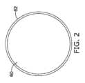
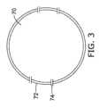
図2~図4は、細胞への電界の印加の様々な影響を示す。可逆的電気穿孔閾値未満の電界強度では、図2に示すように、細胞60の細胞膜62はそのまま維持され、孔は生じない。図3に示すように、より高い電界強度では、可逆的電気穿孔閾値超不可逆的電気穿孔閾値未満で、細胞70の膜72は孔74を発生させる。印加電界とパルス形状の特性に応じて、大小の孔74が生じることが可能であり、発生した孔は、長い時間又は短い時間持続する可能性がある。 Figures 2-4 illustrate the various effects of applying an electric field to cells. At field strengths below the reversible electroporation threshold, the
図4に示すように、さらに高い電界強度では、不可逆的電気穿孔閾値超で、細胞80は、多くの孔84、孔86を伴う膜82を有するようになっている。高振幅又は高出力レベルでは、孔84、孔86は、大きくなりすぎるため、かつ、数が多くなりすぎるため、又はそのいずれか一方のため、細胞が回復できない可能性がある。図4に示されるように、孔は細胞80の左側及び右側に空間的に集中し、細胞膜が印加電界に平行となる領域88には孔がほとんど又はまったくないことにも注目してよい(ここでは、電界は、図4で示された細胞の右側及び左側に配置される電極間で印加されていると想定している)。これは、電界が、細胞膜に対して直交せずに平行に近いため、領域88の膜電位が低いままであることによるものである。 As shown in FIG. 4, at even higher field strengths, above the irreversible electroporation threshold,
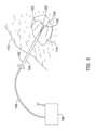
図5は、従来技術である「レビーン(LeVeen、登録商標)」ニードルを示す。米国特許第5,855,576号に記載されているように、この機器は、患者110の標的組織112にアクセスしたあとに伸長又は収縮させることができる複数の組織穿刺電極102に延びているシャフト104を有する挿入可能部分100を含む。この装置の近位端には、電源108への電気配線106が接続されており、RFエネルギーを供給するために使用することができる。 FIG. 5 shows a prior art "LeVeen®" needle. As described in U.S. Pat. No. 5,855,576, the device includes a shaft extending into a plurality of
通常は、レビーンニードルは、標的組織への熱切除を送達するために使用される。たとえば、‘576特許に記載されているように、プレート(単数又は複数)の形態でのリターン電極は、患者の皮膚上に配置してもよく、リターン電極は、他の組織穿刺電極として設置することが可能であり、また、リターン電極は、組織穿刺電極102の近位の、その遠位端の近くのシャフト104上に設置してもよい。 Typically, Levene needles are used to deliver thermal ablation to target tissue. For example, as described in the '576 patent, a return electrode in the form of a plate or plates may be placed on the patient's skin, and the return electrode may be placed as other tissue-piercing electrodes. Alternatively, a return electrode may be placed on the
元の設計に対する機能強化は、たとえば、複数の電極の作動はもちろん、別々に電気的に活性化する電極の個々の作動の両方に関して、組織穿刺電極102の独立した作動を説明している米国特許第6,638,277号において見つけることができる。特許第5,855,576号及び第6,638,277号は、様々な治療送達プローブを示すために参照によって本願に組み込まれる。米国仮特許出願第62/620,873号(その開示は、様々な治療送達プローブを示すものとして参照によって本願に組み込まれる)は、電極のスペーシング、サイズ及び選択における自由度を可能にするレビーンニードル概念の更新及び強化を開示している。 Enhancements to the original design include, for example, the U.S. patent that describes independent actuation of
図6~図8は、様々な波形の特徴を示す。図6について言えば、単相波形は150で示されている。波形150は、ベースライン又は等電位152に対して示されている。理想的な方形波は、振幅154、パルス幅156及びサイクル長158を有することが示されている。波形150は、ベースライン152から指定された振幅154まで垂直に上昇する理想的な方形波として示されている。このような波形を説明するとき、周波数は、通常はサイクル長158の逆数を示す。したがって、たとえば、1マイクロ秒のパルス幅156を有する波形が2マイクロ秒間隔158で送達される場合、その波形の「周波数」は、500kHz(2マイクロ秒の逆数)と記載してもよい。波形150は、電流制御又は電圧制御波形であってもよい。以下でさらに詳しく述べるように、様々な例において、いずれのアプローチを使用してもよい。 6-8 illustrate various waveform characteristics. Referring to FIG. 6, the single phase waveform is indicated at 150.
任意の実際の印加において、生成された波形のエッジは丸くされ、ベースライン152からの上昇は、図7に示すようにさらに丸くされ、162で示されるベースラインからの上方剥離は、立ち上がり時間160が特徴となる。出力の終わりに、立ち下がり時間166を特徴とする非理想的な立ち下がり164もある。波形の実際の印加は、示されているように、臨界減衰信号又は過減衰信号のエッジの信号出力が不足減衰か又は丸くされている場合にたとえば振幅のオーバーシュートを含む可能性のある、ピーク振幅のいくらかの変動も含む。 In any actual application, the edges of the generated waveform will be rounded and the rise from the
いくつかの例において、1つ以上の立ち上がり時間160又は立ち下がり時間166を操作することができる。例示的な例において、システムの出力回路構成は、抵抗器、インダクタなどの、その回路に切り替えた場合に立ち上がり時間を遅らせることができる選択可能な要素を含んでもよい。たとえば、インダクタを流れる電流は瞬時には変化することはできず、したがって、誘導素子を出力回路に切り替えることによって、インダクタが電流を流し始めるときに立ち上がり時間を遅くすることができる。 In some examples, one or more of the
立ち上がり時間及び立ち下がり時間は、いくつかの異なる方法で操作してもよい。たとえば、プロセス設定は、ピーク電圧目標を変更するように選択してもよい。高い目標は、様々な構成要素が指数関数的に応答して、出力回路がオンになるか、又はそれに切り替えられるため、速い立ち上がり時間をもたらすことができる。出力を監視することによって、システムはピーク電圧目標を人工的に増加させて立ち上がり時間を減少させることができ、真のピーク電圧に達すると、システムは、電圧源を切り替えるか、又は出力レギュレーションを使用して(整流器の使用か、又は個々の放電経路による出力電流のリダイレクトなどによる)、電圧出力に制限を加えてもよい。他の例において、様々な立ち上がり時間及び立ち下がり時間を示す様々なHVスイッチタイプを備える、システムに使用可能かつ選択可能な複数の様々なHVスイッチを備えることなどによる構成要素選択を行ってもよい。たとえば、それぞれが様々な立ち上がり/立ち下がり特性を示す3つの出力スイッチが使用可能な場合、システムは、特定の治療出力セッション中に使用するための適切な出力スイッチを選択することにより、長いか又は短い立ち上がり時間/立ち下がり時間を要求するユーザ入力に応答してもよい。ハイパス又はローパスフィルタリングは、スルーレートを制御するための出力回路に切り替えてもよく、又は制御信号回路に切り替えてもよい。たとえば、出力トランジスタの低速ターンオンは、トランジスタそれ自身の立ち上がり時間を遅くすることができ、逆に出力トランジスタの高速ターンオンは、立ち上がり時間を速めることができる。他の例において、立ち上がり時間又は立ち下がり時間のデジタル化制御を可能にする出力回路として、デジタル‐アナログ変換器を使用してもよい。さらに別の例において、デジタル‐アナログ変換器によって出力スイッチへの制御信号を生成することができ、それによって、出力回路構成それ自身へのオン/オフ信号を操作することができる。さらに別の例において、波形発生器及び選択的細胞切除の制御と題された米国仮特許出願第62/819,101号(その開示は、参照によって本願に組み込まれる)に示したコンデンサスタック出力を使用して、迅速な立ち上がり時間は、コンデンサスタックの最上部からの1つのスイッチング出力(又は所望の目標レベル)を用いて達成されてもよく、また、遅い立ち上がり時間は、コンデンサスタックのすべてよりも小さい出力を用いて出力を順にオンさせ、次いでさらにコンデンサスタックを出力に追加することによって達成されてもよい。出力回路構成における適切に配置されたダイオードは、このような操作時のコンデンサスタックの新しく追加された部分の逆電流又は短絡を防止する。 Rise and fall times may be manipulated in several different ways. For example, process settings may be selected to change peak voltage targets. High targets can result in fast rise times because the various components respond exponentially to turn on or switch output circuits. By monitoring the output, the system can artificially increase the peak voltage target to reduce the rise time, and when the true peak voltage is reached, the system can switch the voltage source or use output regulation. The voltage output may be limited (such as through the use of rectifiers or redirection of the output current through individual discharge paths). In other examples, component selection may be made, such as by having a plurality of different HV switches available and selectable in the system, with different HV switch types exhibiting different rise and fall times. . For example, if three output switches are available, each exhibiting various rise/fall characteristics, the system can select the appropriate output switch to use during a particular therapy output session to It may also be in response to user input requesting short rise/fall times. High-pass or low-pass filtering may be switched to the output circuit to control the slew rate, or may be switched to the control signal circuit. For example, a slow turn-on of the output transistor can slow down the rise time of the transistor itself, and conversely, a fast turn-on of the output transistor can speed up the rise time. In other examples, a digital-to-analog converter may be used as an output circuit that allows for digitized control of rise time or fall time. In yet another example, a digital-to-analog converter can generate a control signal to an output switch, thereby manipulating an on/off signal to the output circuitry itself. In yet another example, the capacitor stack output shown in U.S. Provisional Patent Application No. 62/819,101 entitled Waveform Generator and Control of Selective Cell Ablation, the disclosure of which is incorporated herein by reference. Using, a fast rise time may be achieved with one switching output (or desired target level) from the top of the capacitor stack, and a slower rise time may be achieved with one switching output (or desired target level) from the top of the capacitor stack, and a slower rise time may be achieved with one switching output from the top of the capacitor stack This may be achieved by using a small output to turn on the outputs in sequence and then adding more capacitor stacks to the outputs. Properly placed diodes in the output circuitry prevent reverse current or short circuiting of the newly added portion of the capacitor stack during such operations.
図8は、今回は、二相信号についてのさらなる詳細を示す。ここでは、波形は180で示され、最初は182の正パルスであり、すぐ後に190の負パルスが続く。正パルス182は振幅184を有し、負パルス190は、通常は正パルスと電圧は等しいが、正パルスとは逆の極性である振幅192を有する。正パルス182はパルス幅186を有し、負パルス190はパルス幅194を有する。通常は、2つのパルス幅186、194は互いに等しい。示されている信号については、サイクル長は、正パルス182の始めの部分からその後のサイクルの開始まで、196で示されているように決定することができる。同様に、周波数はサイクル長の逆数である。 FIG. 8 shows further details, this time about the two-phase signal. Here, the waveform is shown at 180, starting with a positive pulse at 182 followed immediately by a negative pulse at 190. The
二相信号の典型的な印加又は使用において、その目的は、一部分において、各サイクルの終わりに電荷平衡を達成することである。そのため、二相のパルス幅は等しく保たれ、極性は逆ではあるが振幅も等しい。電圧制御又は電流制御システムのどちらを使用する場合でも、単にパルス幅及び振幅を制御することによって、電荷平衡を合理的に維持することができる。たとえば、電圧制御システムにおいて、電流の流れは、サイクル内で大なり小なり一定であり、サイクル長196はミリ秒範囲以下であることが想定される。すなわち、切除手術時に、細胞が破壊されるにしたがって組織インピーダンスは変化し、一般にインピーダンスを減少させる細胞媒体を排出することが公知であるが、インピーダンスは直ちに変化することはないため、電圧を制御するものではなくても、単純な二相波形の電荷平衡が課題になる。 In the typical application or use of biphasic signals, the purpose is, in part, to achieve charge balance at the end of each cycle. Therefore, the pulse widths of the two phases are kept equal, and although the polarities are opposite, the amplitudes are also equal. Whether using a voltage or current control system, charge balance can be reasonably maintained simply by controlling pulse width and amplitude. For example, in a voltage controlled system, it is assumed that the current flow is more or less constant within a cycle, and that the
位相間の時間188は、正及び負パルス間のベースラインにおいて使われる時間間隔であり、基礎となる回路構成の物理的制約に従って通常は最小化される。したがって、たとえば、第1スイッチをオフにして正パルス182を終了させる必要があり、第2スイッチが負パルス190を開始させるために用いられる場合、デジタル制御を想定して、可能性のある内部短絡を防止するために、システムは、第1スイッチをオフにして、次いで第2スイッチをオンにした後に数デジタルクロックサイクルを終了してもよい。より速い切り替えにより、この位相間の時間を短縮させることができ、この時間間隔188を短縮するために多くのエンジニアリングの努力が行われている。 The time between
たとえば、非常に短い位相間の時間188は、米国特許第10,154,869号に示すような設計を用いて達成することができる。特許第10,154,869号において、インダクタは出力負荷と平行して配置される。電源は、治療送達の初期段階において負荷とインダクタに印加される。電源と負荷/インダクタとの間のスイッチを開くことによって、電源が切断された後、インダクタが負荷から電流を引き出すため、負荷を流れる電流がほぼ瞬時に反転する。 For example, a very
図6~図8から、一般的な使用法の背景が得られる。以下にさらに示すいくつかの実施形態において、単相パルスは、筋肉刺激を防止する電荷平衡に関して二相の成果を達成するために用いられる。本明細書におけるすべての例において、用語「筋肉刺激を引き起こさずに」とは、少しの筋肉刺激は許容されるが、それは該当する介入及び手術領域内で、又は介入もしくは手術領域内で許容される量のみであることに留意する必要がある。たとえば、生じる刺激は、患者が不快に感じるほど強くはない。他の例において、生じる刺激は、組織を除去するための手術が、刺激を受けた患者の動作によって干渉を受けない程度に小さい。他の例において、生じる筋肉刺激は、手術に影響がなく、麻痺薬の投与を必要とせずに手術を行うことが可能である。いくつかの例において、生じる刺激は、プローブの配置と固定に影響を及ぼさないか、又は十分に小さいために、プローブの移動が生じない。 6-8 provide background on common usage. In some embodiments, described further below, monophasic pulses are used to achieve a biphasic outcome with respect to charge balance that prevents muscle stimulation. In all examples herein, the term "without causing muscle stimulation" means that some muscle stimulation is tolerated, but it is tolerated within or within the interventional or surgical field in question. It should be noted that this is only the amount that For example, the resulting stimulation is not so strong that the patient feels uncomfortable. In other examples, the resulting stimulation is small enough that the surgery to remove the tissue is not interfered with by movement of the stimulated patient. In other instances, the resulting muscle stimulation does not affect the surgery, allowing the surgery to be performed without the need for administration of paralytic drugs. In some instances, the resulting stimulus does not affect the placement and fixation of the probe, or is small enough that no movement of the probe occurs.
図9は、ブロック方式の信号発生器を示す。信号発生器200は内蔵型ユニットであってもよく、またそれは、ワイヤ及び無線接続のうちの少なくともいずれか一方とともに接続されたいくつかの個々の構成要素を含んでもよい。制御ブロックは202で示されており、ステートマシン、マイクロコントローラ及び関連するデジタル論理又はマイクロプロセッサの形での複数の論理回路や、さらには、必要に応じてラップトップ又はデスクトップコンピュータなどの既成の演算装置を含んでもよい。メモリ204は、制御ブロック202から独立していてもしていなくてもよく、操作のための実行可能命令セットを格納するだけでなく、システムの動作のログ及び、治療時に受信されるセンサ出力を保管するためにも含まれる。メモリ204は揮発性又は不揮発性メモリであってもよく、光学メディア、デジタルメディア、フラッシュドライブ、ハードドライブ、ROM、RAMなどを含んでもよい。UI又はユーザインタフェース206は、制御ブロックに組み込まれてもよい(制御装置202のためにラップトップ(メモリ204及びUI206のそれぞれを含む)を用いる場合など)。UI206は、必要に応じて、マウス、キーボード、スクリーンタッチスクリーン、マイクロホン、スピーカなどを含んでもよい。 FIG. 9 shows a block-based signal generator. Signal generator 200 may be a self-contained unit, or it may include several individual components connected together with wires and/or wireless connections. The control block is indicated at 202 and includes a plurality of logic circuits in the form of state machines, microcontrollers and associated digital logic or microprocessors, or even off-the-shelf computing devices such as laptop or desktop computers, if desired. It may also include a device. Memory 204, which may or may not be independent of control block 202, stores a set of executable instructions for operation, as well as logs of system operation and sensor outputs received during treatment. Also included to do. Memory 204 may be volatile or non-volatile memory and may include optical media, digital media, flash drives, hard drives, ROM, RAM, and the like. A UI or user interface 206 may be incorporated into the control block (such as when using a laptop (including each of memory 204 and UI 206) for control device 202). UI 206 may include a mouse, keyboard, screen touch screen, microphone, speakers, etc., as appropriate.
電源入力208は、電池(単数又は複数)を含んでもよいが、通常は、線電源を受け取るための壁コンセントに差し込む電気的接続を含む。治療ブロックは210で示され、いくつかの段階を含む。絶縁及び電圧変換回路は212で示され、たとえば、電池又は線電圧を受け入れ、HVストレージ214に格納される高電圧出力に増加させる1つ以上の変圧器又は他の昇圧コンバータ(容量式昇圧変換回路など)を含んでもよい。HVストレージ214は、電池、インダクタ又は他の回路素子を含んでもよいが、通常は、積層型コンデンサなどの容量式ストレージブロックである。HVストレージ214は、ブロック212からHV信号を取得し、経時的にそれを平滑化して、それからHV出力回路216によって送達されるより安定した高電圧出力を提供するのに役立ててもよい。また、HVストレージ214は、長時間にわたってエネルギーを格納して短いバーストで送達することによって、低出力電圧入力が、非常に高い電源出力を生成することを可能にしてもよい。 Power input 208 may include battery(s), but typically includes an electrical connection that plugs into a wall outlet for receiving line power. The treatment block is shown at 210 and includes several stages. Isolation and voltage conversion circuitry is shown at 212, such as one or more transformers or other step-up converters (capacitive step-up converter circuits) that accept battery or line voltage and increase it to a high voltage output that is stored in HV storage 214. ) may also be included. HV storage 214 may include batteries, inductors or other circuit elements, but is typically a capacitive storage block such as a stacked capacitor. HV storage 214 may obtain the HV signal from block 212 and smooth it over time to help provide a more stable high voltage output that is then delivered by HV output circuit 216. HV storage 214 may also allow low output voltage inputs to produce very high power outputs by storing energy over long periods of time and delivering it in short bursts.
HV出力回路216は、218で示されるIOブロックへの高電圧信号の選択的出力を可能にする、たとえば、シリコン制御式整流器、高出力Mosfet及び他の要素などの高電圧スイッチを含む多くのスイッチ及び他の要素を含む出力制御回路であってもよい。IOブロック218は、1つ以上の送達プローブ220からのプラグを受け入れるためのいくつかのコンセントだけでなく、リターン電極として役立てるか、又は単に患者及びシステムを接地するための、患者の身体に配置される1つ以上の不関電極の1つ以上の出力を提供してもよい。 HV output circuit 216 includes a number of switches, including high voltage switches, such as silicon controlled rectifiers, high power Mosfet's and other elements, to enable selective output of high voltage signals to the IO block shown at 218. It may also be an output control circuit including other elements. The IO block 218 is located on the patient's body to serve as a return electrode, or simply to ground the patient and system, as well as several outlets for accepting plugs from one or more delivery probes 220. One or more outputs of one or more indifferent electrodes may be provided.
治療ブロック210へのいくつかの代替的アプローチにおいて、HVストレージから信号を直接に出力するためのスイッチのセットを用いるHV出力216ではなく、共振回路は、HV信号を電源として、共振回路の出力を選択的に切り替えることによって、共振回路の出力を治療送達に用いてもよい。「Hブリッジ」における4つのスイッチのセットを用いてRF回路を駆動するトポロジーは、たとえば米国特許第10,105,172号に示されている。いくつかの実施形態において、個々のパルスの制御は、本発明において、波形発生器及び選択的細胞切除のための制御と題された米国仮特許出願第62/819,101号(その開示は、参照によって本願に組み込まれる)に示すように、駆動RF回路を省略し、単に拡張Hブリッジ回路の1形態に依存することによって達成される。 In some alternative approaches to therapy block 210, rather than HV output 216 using a set of switches to output the signal directly from HV storage, the resonant circuit is powered by the HV signal and outputs the output of the resonant circuit. By selectively switching, the output of the resonant circuit may be used for therapeutic delivery. A topology for driving an RF circuit using a set of four switches in an "H-bridge" is shown, for example, in US Pat. No. 10,105,172. In some embodiments, the control of individual pulses is disclosed in US Provisional Patent Application No. 62/819,101 entitled Waveform Generator and Control for Selective Cell Ablation (the disclosure of which is incorporated herein by reference). This is accomplished by omitting the drive RF circuitry and relying solely on a form of extended H-bridge circuitry, as shown in Embodiment 1 (herein incorporated by reference).
制御ブロック202へのフィードバックを提供するために、1つ以上の検出回路224が含まれてもよい。たとえば、検出回路は、プローブ220への出力ノードの電圧を測定してもよく、組織性状を観察することを可能にするプローブ220に接続する出力ノードに向かう電流を測定してもよい。たとえば、一例として直接変換、遂次近似、ランプ型、ウィルキンソン、積分、デルタコード化、パイプライン化、シグマデルタ、及び時間インターリーブADCなどのうちの少なくともいずれか1つを含む電圧測定回路は当該分野で周知であり、適用に適している場合は、それらのいずれも使用してもよい。電流測定回路構成は、たとえば、トレース抵抗検出、変流器又はロゴスキーコイルなどの、ファラデーの法則に基づく電流センサ、又は1つ以上の伝送路に電気的又は磁気的に接続された磁場センサの使用(ホール効果、フラックスゲート、及び磁気抵抗電流センサのうちの少なくともいずれか1つ)を使用してもよい。安全目的のために、出力回路構成に電流センサを使用して、短絡又は過電流状態を抑えてもよい。 One or more detection circuits 224 may be included to provide feedback to control block 202. For example, the detection circuit may measure a voltage at an output node to probe 220, or may measure a current toward an output node connected to probe 220 that allows tissue properties to be observed. For example, voltage measurement circuits including at least one of direct conversion, successive approximation, ramp type, Wilkinson, integration, delta coding, pipelined, sigma delta, and time interleaved ADCs are known in the art. Any of these may be used if they are well known and suitable for the application. The current measurement circuitry may include, for example, a Faraday's law based current sensor, such as trace resistance sensing, a current transformer or Rogowski coil, or a magnetic field sensor electrically or magnetically connected to one or more transmission lines. (Hall effect, fluxgate, and/or magnetoresistive current sensors) may be used. For safety purposes, current sensors may be used in the output circuitry to suppress short circuit or overcurrent conditions.
他の例において、プローブ220は、温度センサ、力センサ又は化学物質もしくはpHセンサなどのセンサを含んでもよく、それらのいずれも、治療送達時に組織性状を監視するために使用することができる。たとえば、温度センサを使用して、ある領域の温度が閾値温度より高くなっているか、又は上昇傾向を示しているかどうかを観察することによって、電気穿孔などの非熱療法を管理してもよく、その場合、電源出力の1つ以上の要素を減少させて、所望の治療タイプが優位であることを確認してもよい。プローブがこのような部材を含む場合、検出回路224は、感知された信号が制御ブロック202での使用のために調整されることを可能にするために、任意の適切な増幅器、フィルターなどを含んでもよい。 In other examples, probe 220 may include sensors such as temperature sensors, force sensors, or chemical or pH sensors, any of which can be used to monitor tissue properties during therapy delivery. For example, temperature sensors may be used to manage non-thermal therapies such as electroporation by observing whether the temperature of an area is above a threshold temperature or exhibiting an upward trend; In that case, one or more components of the power supply output may be reduced to ensure that the desired treatment type is dominant. If the probe includes such components, detection circuit 224 includes any suitable amplifiers, filters, etc. to enable the sensed signal to be conditioned for use in control block 202. But that's fine.
検出回路224は、以下に述べるように、心調律を捕捉し、治療送達のための生理学的ウィンドウを同定するために、1つ以上の電極(たとえば患者の胸部に配置した表面電極)とともに使用するのに適した心調律センサを含んでもよい。治療のための生理学的ウィンドウを同定するための心臓信号は、代わりに、クリニック内ECGモニター、心臓モニター、ペースメーカ又は除細動器などの埋め込み型医療機器、又は心調律を検知する様々なウェアラブル製品から受信してもよい。 Detection circuit 224 is used in conjunction with one or more electrodes (e.g., surface electrodes placed on the patient's chest) to capture cardiac rhythm and identify physiological windows for therapy delivery, as described below. It may also include a heart rhythm sensor suitable for. Cardiac signals to identify physiological windows for treatment may alternatively be obtained from in-clinic ECG monitors, cardiac monitors, implantable medical devices such as pacemakers or defibrillators, or various wearable products that detect heart rhythm. It may be received from
任意選択で、「他の治療」ブロック222を含めてもよい。「他の」治療は、たとえば、追加の治療を提供するため、送達される治療を促進するため、又は免疫反応を引き起こして切除後の身体の治癒自体を容易にするための化学薬品又は生物学的製剤の送達を含んでもよい。このような他の治療222は、たとえば、シリンジ又はカテーテル又はプローブによって患者に送達される材料のリザーバ(詰め替え可能であってもよい)を含んでもよい。「他の治療」222は、電気的に送達される治療の切除効果を、促進するため、増強するため、相乗的に発揮するため、又は別に追加するための物質を導入することを含んでもよい。たとえば、物質注入と電界印加の組み合わせによる不可逆的電気穿孔と題された米国特許出願第16/188,343号(その開示は、参照によって本願に組み込まれる)に開示されているように、電界効果を改変又は増強するために物質を注入してもよい。 Optionally, an “other treatment” block 222 may be included. “Other” treatments may include, for example, chemicals or biological agents to provide additional treatment, to enhance the treatment being delivered, or to provoke an immune response to facilitate the body's own healing after resection. delivery of targeted formulations. Such other treatments 222 may include, for example, a reservoir of material (which may be refillable) delivered to the patient by a syringe or catheter or probe. "Other treatments" 222 may include introducing substances to enhance, enhance, synergize, or otherwise add to the ablation effects of the electrically delivered treatments. . For example, as disclosed in U.S. patent application Ser. Substances may be injected to modify or enhance.
いくつかの例において、必要に応じて免疫反応を促進して、電気的切除の前、最中又は後に組織冷却を可能にする凍結療法をこのシステムに組み込んでもよい。凍結療法は、たとえば、治療プローブ220上のバルーンを用いて送達されてもよく、亜酸化窒素などの加圧流体源に接続されたバルーン内のノズルとは別に提供されてもよい。たとえば米国特許第6,428,534号に開示されているように、ノズルから排出された加圧流体は、膨張するか、又は液体からガスへの相変化を行って局所冷却を引き起こす。他の例において、流体(ガス又は液体)は、外部で冷却され、凍結目的でカテーテルによって導入されてもよく、これに変えて外部で熱せられ、加熱切除目的で、カテーテルによって導入されてもよい。 In some examples, cryotherapy may be incorporated into the system to optionally stimulate the immune response and allow for tissue cooling before, during, or after electrical ablation. Cryotherapy may be delivered using a balloon on the treatment probe 220, for example, and may be provided separately from a nozzle within the balloon connected to a source of pressurized fluid, such as nitrous oxide. For example, as disclosed in US Pat. No. 6,428,534, pressurized fluid discharged from a nozzle expands or undergoes a phase change from liquid to gas to cause localized cooling. In other examples, the fluid (gas or liquid) may be externally cooled and introduced by the catheter for freezing purposes, or alternatively may be externally heated and introduced by the catheter for thermal ablation purposes. .
さらに他の例において、他の治療222は、機械的エネルギー(たとえば超音波)又は、たとえば、標的組織にレーザーエネルギーが送達されるのを可能にするプローブを通して延びている光ファイバーに接続されたレーザー源(たとえば垂直共振器面発光型レーザー)を用いる光エネルギーなどのエネルギーの送達を含んでもよい。いくつかの例において、指摘したように、標的組織を破壊するための主要アプローチとして使用されない場合であっても、免疫反応を引き起こすための二次の又は「他の」治療を使用してもよい。 In yet other examples, other treatments 222 include mechanical energy (e.g., ultrasound) or a laser source connected to an optical fiber extending through a probe that allows laser energy to be delivered to the target tissue, for example. (e.g., a vertical cavity surface emitting laser). In some instances, as noted, secondary or "other" treatments may be used to elicit an immune response even if not used as the primary approach to destroying the target tissue. .
図10~図11は、電極がその近傍にある標的組織を示す。図10に示すように、標的組織300は、複数の電極1~6によって囲まれていてもよい。上記の図5に示すプローブは、標的組織300の周りにいくつかの電極を容易に配置するために、個々の電極1~6を標的の周りの組織に穿刺し、進めて用いてもよい。従来の二相印加において、電極は対又は群で、又は遠隔のリターン電極に関連する完全群で使用してもよく、正相信号の直後に、ほぼ等しいが逆の電圧又は電流の負相信号を用いてもよい。このような使用と対照的に、本発明は、代わりに、治療出力の空間多重化を用いて、二相治療の副作用の低減(特に筋肉刺激)を利用しながら、単相出力の有効性をも備えた治療を送達する。そうするための一例において、電極を使用して、以下のようなラウンドロビン方式で単相治療を送達してもよい。 Figures 10-11 show target tissue with electrodes in its vicinity. As shown in FIG. 10, target tissue 300 may be surrounded by multiple electrodes 1-6. The probe shown in FIG. 5 above may be used to easily place several electrodes around the target tissue 300 by puncturing and advancing individual electrodes 1-6 into the tissue around the target. In a conventional two-phase application, the electrodes may be used in pairs or groups, or in complete groups associated with a remote return electrode, with a positive sequence signal immediately followed by a negative sequence signal of approximately equal but opposite voltage or current. may also be used. In contrast to such uses, the present invention instead utilizes spatial multiplexing of the treatment output to take advantage of the reduced side effects (particularly muscle stimulation) of the biphasic treatment while leveraging the effectiveness of the monophasic output. Deliver complete treatment. In one example for doing so, electrodes may be used to deliver monophasic therapy in a round robin manner as follows.
この例では、各出力は単相波形であってもよい。シーケンス中のパルス幅と振幅は、必要に応じて、一定に保ってもよく、又は変化させてもよい。一例において、パルス幅は、各パルスについて0.1~10マイクロ秒の範囲にある。振幅は、電圧又は電流に基づいて決定してもよく、また、たとえば、視覚化又は距離推定を用いて決定して、1センチメートルあたりのボルトで出力を提供してもよい。たとえば、出力振幅は、標的組織300のIRE閾値を超えると同時に、このような距離を考慮に入れて選択されてもよい。一例において、X線撮影又は他の視覚化によって行うことができる計算、又はプローブの展開領域の組織の単位距離あたりのインピーダンスを推定し、電極1と4の間のインピーダンスを測定し、次いで距離を計算することによって決定することができる計算、電極1と4は、2センチメートル離れていると推定してもよい。In this example, each output may be a single phase waveform. The pulse width and amplitude during the sequence may be held constant or varied as desired. In one example, the pulse width ranges from 0.1 to 10 microseconds for each pulse. The amplitude may be determined based on voltage or current, and may be determined using visualization or distance estimation, for example, to provide an output in volts per centimeter. For example, the output amplitude may be selected to exceed the IRE threshold of the target tissue 300 while taking such distance into account. In one example, calculations that can be made by radiography or other visualization, or estimating the impedance per unit distance of tissue in the deployment area of the probe, measure the impedance between electrodes 1 and 4, and then calculate the distance. Calculations that can be determined by calculating, electrodes 1 and 4 may be estimated to be 2 centimeters apart.
治療は、上記のチャートを参照して、任意の順序で順次送達されてもよい。すなわち、ABCDEFがその順序であってもよい。いくつかの例において、シーケンスADは、名前を書かなくても本質的に二相出力の形態であり、そのため単相出力と同等に有効でない可能性があり、回避してもよい。いくつかの例において、電極ペアリングの連続又は瞬時の反転を避けるために、直前のパルス送達から、任意の所定のパルス送達に対して少なくとも1つの電極が異なることを要求するルールを設定してもよい。 Treatments may be delivered sequentially in any order with reference to the chart above. That is, the order may be ABCDEF. In some instances, the sequence AD is essentially a form of two-phase output, even without a name, and therefore may not be as effective as a single-phase output and may be avoided. In some examples, to avoid continuous or instantaneous reversals of electrode pairing, a rule is set that requires at least one electrode to be different for any given pulse delivery from the previous pulse delivery. Good too.
いくつかの例において、完了したシーケンスは、以下の2つのルールのそれぞれを満たす時間間隔(単数又は複数)内に完了するパルス列として送達される。
‐電荷平衡ルール:以下の範囲内の電荷平衡又は電荷平衡の近似を与えることによってパルス列が完了する。
○組織型及び水分含有量などの因子に依存する場合がある、周辺組織の時定数よりも小さい時間間隔。周辺組織の時定数は、電界内の組織及び細胞の複素インピーダンスを反映する。たとえば、2つの電極間の組織の時定数は、その複素インピーダンスによって決定される。簡略化したモデルでは、時定数は、2つの電極間で生成される電界内の、細胞を含む組織の抵抗を掛けた静電容量になる。すでに分極化されている細胞又は組織は、より大きい又はより小さい有効時定数を有していてもよい。
○約1ミリ秒未満の時間間隔
○患者を試験することによって決定された、患者が許容できる最大時間間隔。たとえば、患者を試験するために、治療出力は、ある時間間隔によって分離された第1部分及び第2部分を含んでもよく、第1部分と第2部分を分離する間隔は、筋収縮が認められるまで、患者が収縮又は張力を感じることを報告するまで、又は患者によって不快感が示されるまで延ばすことができ、治療の第1部分は、電荷の不均衡をもたらす第1単相パルス(単数又は複数)であり、治療の第2部分は、電荷の不均衡を取り除くように構成されている。たとえば、二相出力は、位相間の時間(図8、188)を個々のパルス幅の倍数まで制御し広げることによって、たとえば数十マイクロ秒又は数百マイクロ秒、又はさらに患者が許容できる数ミリ秒まで分離され、なお以下に示す治療完了ルールの範囲内にとどまる、5マイクロ秒パルスを用いて、2つの部分に分離してもよい。
‐治療完了ルール:パルス列は、患者の心調律などの非治療因子の観察によって決定される生理学的ウィンドウ内で送達される。In some examples, a completed sequence is delivered as a train of pulses that completes within a time interval or intervals that satisfy each of the following two rules:
- Charge balance rules: the pulse train is completed by providing a charge balance or an approximation of the charge balance within the following ranges:
o Time interval smaller than the time constant of the surrounding tissue, which may depend on factors such as tissue type and water content. The time constant of the surrounding tissue reflects the complex impedance of the tissue and cells within the electric field. For example, the time constant of tissue between two electrodes is determined by its complex impedance. In a simplified model, the time constant is the capacitance multiplied by the resistance of the tissue containing the cells within the electric field generated between the two electrodes. Cells or tissues that are already polarized may have a larger or smaller effective time constant.
o A time interval of less than approximately 1 millisecond o The maximum time interval that the patient can tolerate, as determined by testing the patient. For example, to test a patient, the treatment output may include a first portion and a second portion separated by an interval of time, the interval separating the first portion and the second portion being the interval during which muscle contraction is observed. The first part of the treatment consists of a first monophasic pulse (single or plural), and the second portion of the treatment is configured to remove the charge imbalance. For example, biphasic output can be achieved by controlling and spreading the time between phases (FIG. 8, 188) to multiples of the individual pulse widths, e.g. tens or hundreds of microseconds, or even a few millimeters as tolerated by the patient. The two parts may be separated using a 5 microsecond pulse that is separated by up to seconds and still remains within the treatment completion rules set forth below.
- Treatment completion rule: pulse trains are delivered within a physiological window determined by observation of non-therapeutic factors such as the patient's heart rhythm.
治療完了ルールに関しては、心臓をドライバーとして、心調律は、R波、QRS群、P波及びT波として一般に公知の様々な構成要素を含む。切除目的での非心臓組織の刺激は、心調律の妨げになるべきではなく、心臓は、R波ピーク(又はQRS群の終点)とT波との間の間隔では電気信号の干渉の影響を受けにくい可能性がある。この間隔は、ST間隔(S波はQRS群の終点となる)と呼ばれることもある。特定の患者のST間隔は数十ミリ秒持続する可能性があり、5~100ミリ秒の範囲である可能性がある。おおよそ60ミリ秒が健常者に一般的であるが、本明細書で説明した治療は必ずしも健康な人や一般的な人を対象とするものではないため、ST間隔は「一般的」でない可能性がある。一例において、R波が感知されると、治療バーストは、R波検出又はR波ピークから約50ミリ秒の遅延の後に送達される。いずれにしても、いくつかの例において、治療はST間隔ウィンドウ内で開始され、完了される。ST間隔又は他の生理学的に有用なウィンドウの同定に有用な心臓信号は、別の機器(外部又は埋め込み型の)から得られてもよく、又は患者の内部もしくは表面に配置された電極から心臓信号を受信するための入力を有する治療発生装置によって感知されてもよい。他の情報源は、ドライバーであってもよい。たとえば、横隔膜運動の検出は、患者がいつ吸気又は呼気したかに関する治療の送達の時間を設定するのに役立つ可能性がある。 With respect to treatment completion rules, with the heart as the driver, cardiac rhythm includes various components commonly known as R waves, QRS complexes, P waves, and T waves. Stimulation of non-cardiac tissue for ablation purposes should not disturb the cardiac rhythm; the heart is immune to the effects of electrical signal interference in the interval between the R-wave peak (or the end of the QRS complex) and the T-wave. It may be difficult to receive. This interval is sometimes referred to as the ST interval (the S wave marks the end of the QRS complex). A particular patient's ST interval can last tens of milliseconds and can range from 5 to 100 milliseconds. Although approximately 60 milliseconds is typical for healthy individuals, the ST interval may not be "typical" as the treatments described herein are not necessarily intended for healthy or general populations. There is. In one example, when an R-wave is sensed, the therapy burst is delivered after a delay of about 50 milliseconds from R-wave detection or R-wave peak. In any event, in some instances, treatment is initiated and completed within the ST interval window. Cardiac signals useful for identifying ST intervals or other physiologically useful windows may be obtained from separate equipment (external or implanted) or from electrodes placed inside or on the patient's surface. It may be sensed by a therapy generating device having an input for receiving the signal. Other sources of information may be drivers. For example, detection of diaphragm movement may help time the delivery of therapy relative to when the patient inhales or exhales.
他の例において、これらのタイミングルールの一方、他方又は両方を省いてもよい。いくつかの例において、パルス列が1ミリ秒又は800マイクロ秒又は500マイクロ秒以内に平衡電荷状態に戻らなければならないというルールを設定することなどによってウィンドウを近似してもよい。 In other examples, one, the other, or both of these timing rules may be omitted. In some examples, the window may be approximated, such as by setting a rule that the pulse train must return to an equilibrium charge state within 1 millisecond or 800 microseconds or 500 microseconds.
他の例において、複数の電極をカソードとして一緒にまとめることができる。 In other examples, multiple electrodes can be grouped together as a cathode.
さらにもう1つの例において、複数の電極をアノードとして一緒にまとめてもよい。In yet another example, multiple electrodes may be grouped together as an anode.
アノードとカソードの両方とも一緒にまとめることができる。Both the anode and cathode can be grouped together.
このような様々なペアリングを使用してもよい。上記で述べたように、治療はルールセットに従って送達することができる。治療を送達するための装置は、必要に応じて、格納された命令セット又はハードワイヤリングにこのようなルールセットを組み込んでもよい。Various such pairings may be used. As mentioned above, treatment can be delivered according to a set of rules. A device for delivering therapy may incorporate such a rule set into a stored instruction set or hardwiring, if desired.
上記を考慮すれば、例示的な例は、パルス列内の電極の選択された対又は群間で複数の単相出力を送達することを含む治療送達法の形態を取る。さらに、治療送達及びパルス列は、パルス列内の連続する各パルスが、直前のパルスとは異なる少なくとも1つの電極を使用することを要求する第1ルールを用いて送達されてもよい(以前用いられた電極を省くか、1つの電極を追加するか、又は1つ以上の電極を1つ以上の他の電極と交換するかのいずれかで)。第2ルールは、周辺組織の時定数未満又は1ミリ秒未満などの事前設定された時間間隔内でパルス列が送達されることを要求する。第3ルールは、指定された生理学的ウィンドウ内でパルス列が送達されることを要求する。ここで、この生理学的ウィンドウは、心臓が電気的干渉に不応性であるか、又は少なくとも比較的影響を受けにくい心周期内の時間に該当する。他の例示的な例は、第1、第2及び第3ルールを実行形式で保存するか、又は組み込むように構成されている、上記の図9に示されているような信号発生器の形態を取ってもよい。これらの例示的な例のそれぞれについて、出力治療パルスは、たとえば、パルスあたり約0.1~10マイクロ秒の範囲であってもよく、パルス列は任意の適切な長さ、たとえば約4~約100パルスであってもよく、パルス列は繰り返されてもよい。 In view of the above, an illustrative example takes the form of a therapy delivery method that includes delivering multiple monophasic outputs between selected pairs or groups of electrodes within a pulse train. Additionally, therapy delivery and pulse trains may be delivered using a first rule that requires each successive pulse in a pulse train to use at least one electrode different from the immediately preceding pulse (as previously used either by omitting an electrode, adding one electrode, or replacing one or more electrodes with one or more other electrodes). The second rule requires that the pulse train be delivered within a preset time interval, such as less than the time constant of the surrounding tissue or less than 1 millisecond. The third rule requires that the pulse train be delivered within a specified physiological window. Here, this physiological window corresponds to a time within the cardiac cycle during which the heart is refractory to, or at least relatively unsusceptible to, electrical interference. Other illustrative examples include the configuration of a signal generator as shown in FIG. 9 above, which is configured to store or incorporate the first, second, and third rules in executable form. You may take . For each of these illustrative examples, the output therapy pulses may range, for example, from about 0.1 to 10 microseconds per pulse, and the pulse train may have any suitable length, such as from about 4 to about 100 microseconds. It may be a pulse, and the pulse train may be repeated.
いくつかの例において、様々な電極を用いて治療が送達されるとき、各電極に出入りする出力電流を追跡してもよい。パルス列又は一連のパルス列の終わりに、各電極を流れる電流の合計を決定してもよく、任意の1つの電極界面で任意の蓄積電荷を相殺すると考えられる所定量の電流又は電圧を送達することによる1つ以上の補正出力が生成されてもよい。様々な例示的な実施例は、送達される電荷を監視し、次いで「補正」パルスを提供して電極表面上のいずれか1つ以上の任意の蓄積電荷を打ち消すという組み合わせを含んでもよい。補正パルスは、特に、電流制御出力ではなく、電圧制御出力が用いられる場合に役立つ可能性がある。 In some examples, the output current to and from each electrode may be tracked as therapy is delivered using the various electrodes. At the end of a pulse train or series of pulse trains, the total current flowing through each electrode may be determined, by delivering a predetermined amount of current or voltage that is believed to offset any accumulated charge at any one electrode interface. One or more corrected outputs may be generated. Various exemplary embodiments may include a combination of monitoring the delivered charge and then providing a "correction" pulse to counteract any accumulated charge on any one or more of the electrode surfaces. Correction pulses may be particularly useful when voltage-controlled outputs are used rather than current-controlled outputs.
図11は他の例を示す。ここでは、不規則な形状の標的組織320の周りに電極のアレイが示されている。この例において、電極は、互いに、又は標的組織320から、すべて等距離にあるわけではない。距離/スペースのこのような変化を考慮に入れるために、治療出力が送達される前に、追加的な一連の計算を行ってもよい。可視化ツールを用いるか、又は組織インピーダンスに依拠して、治療に使用する様々な電極対間の距離を計算してもよい。その場合、治療シーケンスは次のとおりである。 FIG. 11 shows another example. Here, an array of electrodes is shown around an irregularly shaped
ここで、V1は、それを送達するために使用される電極(1,4)の対を考慮して、標的組織320のIRE閾値を超えるように選択された電圧である。したがって、たとえば、電極1と4が3cm離れ、電極3と6が2cm離れている場合、V1は電圧V3の約1.5倍として選択される可能性がある。大まかに700v/cmというIREの要件を用いれば、V1は2100ボルトになり、V3は1400ボルトになる可能性がある。上記の、一緒にまとめた電極も、必要に応じて用いることができる。Here, V1 is a voltage selected to exceed the IRE threshold of the
示されたパルス列内で、必要に応じてV1とV1*とは同じであってもよい。あるいは、ステップA中に、インピーダンス又は他の因子を監視することによって、ステップDで、たとえば、インピーダンスが高すぎる場合には電圧を上げ、インピーダンスが低すぎる場合には電圧を下げる変更を通知してもよい。しかしながら、一般に、1つのパルス列内では、アスタリスクの付いた電圧は、以前の送達と同じになる可能性が高い。Within the pulse train shown, V1 and V1* may be the same if desired. Alternatively, monitoring the impedance or other factors during step A may signal a change in step D, e.g., increasing the voltage if the impedance is too high or decreasing the voltage if the impedance is too low. Good too. However, in general, within one pulse train, the asterisked voltage is likely to be the same as the previous delivery.
ABCDEFのパルス列については、治療が送達されるときに、一連の測定インピーダンスを生成することができる。複数のパルス列が送達されるとき、治療が機能していると想定して、細胞が破裂し、細胞膜に形成された開口部を通じて流体が排出され、それによって一般にインピーダンスが低下するため、測定インピーダンスが変化する可能性がある。インピーダンスが低下するとき、電流が上昇して熱効果が大きくなることがさらに懸念される可能性がある。したがって、いくつかの例において、各パルス列が完了したとき、それに続くパルス列を送達する前に、インピーダンスをチェックし、出力電圧を下げて、熱効果を回避又は制限してもよい。 For an ABCDEF pulse train, a series of measured impedances can be generated as therapy is delivered. Assuming the therapy is working, when multiple pulse trains are delivered, the measured impedance is Subject to change. When the impedance decreases, the current increases and thermal effects become more significant, which can be a further concern. Thus, in some examples, upon completion of each pulse train and before delivering a subsequent pulse train, the impedance may be checked and the output voltage reduced to avoid or limit thermal effects.
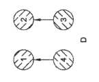
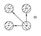
図10~図11で示されている例は、基本的に電極対を使用して電荷平衡を生じるための整合出力を提供するが、代わりに他のアプローチを使用してもよい。図12は、以下のようなステップA、B、C及びDによる例を示す。 Although the examples shown in FIGS. 10-11 essentially use electrode pairs to provide matched outputs to create charge balance, other approaches may be used instead. FIG. 12 shows an example with steps A, B, C and D as follows.
このパルス列において、治療送達に用いられる各電極は、少なくとも1回はアノードとして、また少なくとも1回はカソードとして用いられる。各パルスは単相であってもよく、したがってステップA~Dの治療パルスのいずれも個々には電荷平衡をもたらさないが、パルス列全体で電荷平衡をもたらす。いくつかの例において、一般に、V1~V4のそれぞれは同じであってもよい。In this pulse train, each electrode used for therapy delivery is used at least once as an anode and at least once as a cathode. Each pulse may be monophasic, such that none of the treatment pulses of steps AD individually provide charge balance, but the pulse train as a whole provides charge balance. In some examples, generally each of V1-V4 may be the same.
このアプローチのために、V1~V4がすべて同じ場合は、各ステップで電流の流れを監視し、完了時に1つ以上の補正出力を使用することが役に立つ可能性がある。たとえば、電極の間隔は均一ではない可能性があり、そのためあるステップでは他のステップよりも電流が多く流れ、1つ以上の電極界面で電荷の不均衡が残る場合がある。いくつかの例において、各電極が、一般にバランスのとれた方法で使用される限り、これで十分な可能性がある。他の例において、監視は、電極の電荷不均衡が閾値を超えると決定するなど、電荷平衡閾値に関して行ってもよく、補正パルス(単数又は複数)が生成されてもよい。 For this approach, if V1-V4 are all the same, it may be useful to monitor the current flow at each step and use one or more correction outputs upon completion. For example, the spacing of the electrodes may not be uniform, so that more current flows in some steps than in others, leaving a charge imbalance at one or more electrode interfaces. In some instances, this may be sufficient as long as each electrode is used in a generally balanced manner. In other examples, monitoring may be performed with respect to a charge balance threshold, such as determining that the charge imbalance of the electrodes exceeds a threshold, and a correction pulse(s) may be generated.
他の例において、V1~V4は、インピーダンスを考慮に入れて変更してもよい。インピーダンスは、先行するパルス列で、又は治療目的で使用されるよりも低い出力電圧で予備試験することによって、パルス列が送達される前に測定することができる。各出力対のインピーダンス(すなわち、ステップAでは1~2で、ステップBでは2~3で、など)を知ることによって、一連のインピーダンスI(1,2)、I(2,3)、I(3.4)、I(4,1)が得られ、次のように行ってV1~V4を算出してもよい。
V1=Vn×I(1,2)/In
V2=Vn×I(2,3)/In
V3=Vn×I(3,4)/In
V4=Vn×I(4,1)/In
式中、Vnは公称電圧であり、Inは公称インピーダンスである。Inは、4つのインピーダンスI(1,2)、I(2,3)、I(3.4)、I(4,1)のセットの平均インピーダンスにすることもできる。少なくとも一次近似で、このアプローチは各ステップにおける電流の流れを均等化する。他の例において、印加電圧を変更するのではなく、可変抵抗を電流流路に切り替えるか、又は電流流路から切り替えて、各ステップにおいて治療出力から見たインピーダンスを同じにすることができる。In other examples, V1-V4 may be changed to take impedance into account. Impedance can be measured before a pulse train is delivered by pretesting with a preceding pulse train or at a lower output voltage than used for therapeutic purposes. By knowing the impedance of each output pair (i.e. 1 to 2 for step A, 2 to 3 for step B, etc.), a series of impedances I(1,2), I(2,3), I( 3.4), I(4,1) is obtained, and V1 to V4 may be calculated as follows.
V1=Vn×I(1,2)/In
V2=Vn×I(2,3)/In
V3=Vn×I(3,4)/In
V4=Vn×I(4,1)/In
where Vn is the nominal voltage and In is the nominal impedance. In can also be the average impedance of a set of four impedances I(1,2), I(2,3), I(3.4), I(4,1). At least to a first order approximation, this approach equalizes the current flow at each step. In other examples, rather than changing the applied voltage, a variable resistor can be switched into or out of the current flow path to provide the same impedance seen by the treatment output at each step.
いくつかの例において、補正修正は、インピーダンス又は距離を算出することによって残留電荷を減少させる保護的アプローチとして、パルス列内のパルスごとに振幅ではなくパルス幅を変更することであってもよい。たとえば: In some examples, the corrective modification may be to change the pulse width rather than the amplitude for each pulse in the pulse train as a protective approach to reduce residual charge by calculating impedance or distance. for example:
ここで、たとえば、電極1と2の間のインピーダンスが電極3と4の間のインピーダンスよりも低いためにステップAが他のステップよりも高い電流の流れを有する場合、PW1を短くして各ステップの電流の流れを等しくしてもよい。各ステップで送達される電荷は次のとおりである。
Q1=V1×PW1/I(1,2)
Q2=V1×PW2/I(2,3)
Q3=V1×PW3/I(3,4)
Q4=V1×PW4/I(4,1)
等化計算を行い、得られたパルス幅を治療送達に用いてもよい。たとえば、PWnを公称パルス幅とし(これはユーザが入力してもよいし、システムデフォルトにしてもよい)、Inを公称インピーダンスとして、以下を用いてパルス幅を調整してもよい。
PW1=PWT×I(1,2)/In
PW2=PWT×I(2,3)/In
PW3=PWT×I(3,4)/In
PW4=PWT×I(4,1)/In
したがって、これらの式において、インピーダンスが高いほどパルス幅が長くなり、その特定の治療送達ベクターに関連する電流を低下させる原因となる。公称インピーダンスInではなく、上記式は、インピーダンスI(1,2)、I(2,3)、I(3,4)、I(4,1)のセットの平均インピーダンスを使用してもよい。求めるパルス幅は、たとえば、計算が、公称値に対して一定の量又は百分率以内のパルス幅に調節することを要求することによる、たとえば数マイクロ秒又は20~30パーセント以下の調整を可能にすることによる、特定の境界条件に制限してもよい。たとえば、10マイクロ秒の公称パルス幅を用いる場合、最大調整パルス幅は12マイクロ秒であり、最小は8マイクロ秒(プラス/マイナス2マイクロ秒、又はプラスマイナス20%)であってもよい。いくつかの例において、変更制限は公称値の25%、最大2マイクロ秒であってもよい。Now, if, for example, step A has a higher current flow than the other steps because the impedance between
Q1=V1×PW1/I(1,2)
Q2=V1×PW2/I(2,3)
Q3=V1×PW3/I(3,4)
Q4=V1×PW4/I(4,1)
Equalization calculations may be performed and the resulting pulse width used for therapy delivery. For example, where PWn is the nominal pulse width (which may be entered by the user or the system default) and In is the nominal impedance, the pulse width may be adjusted using:
PW1=PWT×I(1,2)/In
PW2=PWT×I(2,3)/In
PW3=PWT×I(3,4)/In
PW4=PWT×I(4,1)/In
Therefore, in these equations, the higher the impedance, the longer the pulse width, causing the current associated with that particular therapeutic delivery vector to drop. Rather than the nominal impedance In, the above equation may use the average impedance of the set of impedances I(1,2), I(2,3), I(3,4), I(4,1). The desired pulse width allows adjustment by, for example, a few microseconds or 20-30 percent or less, for example by requiring calculations to adjust the pulse width within a certain amount or percentage relative to the nominal value. It may also be limited to certain boundary conditions. For example, using a nominal pulse width of 10 microseconds, the maximum adjusted pulse width may be 12 microseconds and the minimum may be 8 microseconds (plus/
さらに別の例において、一般的アプローチ又はデフォルトアプローチは、各ステップで等しい電圧を提供して、出力を単純化することであってもよい。患者に筋肉刺激が発生していることが認められた場合はインピーダンスを計算して、電圧を変更するか、又はパルス幅(単数又は複数)を変更するか、又は治療経路の抵抗を追加もしくは削除するなどの補正機能を作動させてもよい。同様に、パルス列又は一連のパルス列の最後にパルスを追加して残留電荷を除去することによって、補正機能を印加してもよい。しかしながら、パルス列の最後にこのような機能を送達することは、患者に埋め込まれたままではない切除療法の状況では有用性が低い可能性がある。筋肉刺激の短期間の影響は、電極/組織の境界面の分解を導く長期不均衡を、回避するというよりも、追跡する因子である。代わりに、治療送達中に電荷平衡を監視し、電荷の不均衡閾値が計算又は検出されたときに補正出力を出すことによって補正出力を決定してもよい。 In yet another example, a common or default approach may be to provide equal voltages at each step to simplify the output. If the patient is found to be experiencing muscle stimulation, calculate the impedance and change the voltage or pulse width(s) or add or remove resistance in the treatment path. You may activate a correction function such as Similarly, a correction function may be applied by adding a pulse at the end of a pulse train or series of pulses to remove residual charge. However, delivering such a function at the end of a pulse train may be less useful in ablative therapy situations where it does not remain implanted in the patient. The short-term effects of muscle stimulation are a factor that tracks rather than avoids long-term imbalances that lead to degradation of the electrode/tissue interface. Alternatively, the correction output may be determined by monitoring charge balance during therapy delivery and providing a correction output when a charge imbalance threshold is calculated or detected.
図13は他の例を示す。今回は、電極を4段階の治療出力にグループ化する。 FIG. 13 shows another example. This time, we will group the electrodes into four levels of treatment output.
同様に、電圧V1~V4は、各ステップで等しくてもよく、又は上記の図12に関して説明した方法と原理を用いて異なるものにしてもよい。また、印加されるパルス幅は、上記のように修正してもよい。Similarly, voltages V1-V4 may be equal at each step or may be different using the methods and principles described with respect to FIG. 12 above. Additionally, the applied pulse width may be modified as described above.
図14は、交互の電極の対が、交互にアノードとカソードになっているさらに他の例を示す。ここでは、電極1と3は1つの群であり、電極2,4は他の群である。治療アプローチ又はパターンは、アノード/カソードとしての2つの群の間で交互に行われる。この例は、各群の極性を完全に逆転させるという点でいくつかの以前の例とは異なる。その切り替えが迅速に行われる場合、出力は実質的に二相治療になる。そのため、このシステムは、1つ以上の追加の制約を加える。例示的な例において、ステップAとBの間で瞬時又はほぼ瞬時の極性切り替えが行われる二相アプローチではなく、下記のパターンを使用してもよい。 FIG. 14 shows yet another example in which alternating pairs of electrodes are alternately anodes and cathodes. Here,
ここで、T1はPW1以上であり、T2はPW2以上である。この例において、PW1及びPW2又はPW1もしくはPW2は、0.1~10マイクロ秒の範囲であってもよく、それより長いか又は短い範囲であってもよい。電極1、2、3及び4への接続を開放するのではなく、チャートに示すように、システムは、それぞれを基準電圧に接地又は接続してもよい。Here, T1 is greater than or equal to PW1, and T2 is greater than or equal to PW2. In this example, PW1 and PW2 or PW1 or PW2 may be in the range of 0.1 to 10 microseconds, or may be in a longer or shorter range. Rather than opening the connections to
上記の例において、いくつかの実施態様において、アノードとして識別される電極を、接地に対して負電圧を印可するために使用してもよく、一方、正電圧はカソードによって印加される。他の例において、アノードは単に接地されているか、又はシステムの基準電極である。 In the example above, in some implementations, an electrode identified as an anode may be used to apply a negative voltage with respect to ground, while a positive voltage is applied by the cathode. In other examples, the anode is simply grounded or is the reference electrode for the system.
図15は他の例を示す。ここでは、出力のセットは、単一のカソードを使用し、他の電極はアノードとして機能する。 FIG. 15 shows another example. Here, the set of outputs uses a single cathode, and the other electrodes serve as anodes.
再度、電流の流れは、出力電極の全部又は一部を介して監視してもよく、また所望の程度の電荷平衡を維持するために、電圧レベル及びパルス幅のうちの少なくともいずれか一方の管理又は補正パルスの印加を使用してもよい。Again, current flow may be monitored through all or part of the output electrodes, and the voltage level and/or pulse width may be controlled to maintain the desired degree of charge balance. Alternatively, the application of correction pulses may be used.
これらの限定されない例のそれぞれは、単独で通用することもできるが、他の例の1つ以上と様々な順列又は組み合わせで組み合わせることもできる。
上記の詳細な説明には、発明の詳細な説明の一部を構成する添付図面への参照が含まれている。図面は、本発明を実施することができる特定の実施形態を例示として示している。これらの実施形態は、本明細書では「実施例」とも呼ぶ。このような例は、図示又は記載されているものに加えて要素を含むことができる。しかしながら、本発明者らは、図示又は記載されている要素のみが提供される例も企図する。さらに、本発明者らは、特定の例(又はその1つ以上の態様)に関して、又は本明細書に図示又は記載されている他の例(又はその1つ以上の態様)に関して、図示又は記載されているこれらの要素(又はその1つ以上の態様)の任意の組み合わせ又は順列を用いる例も企図する。Each of these non-limiting examples can stand alone or can be combined with one or more of the other examples in various permutations or combinations.
The above detailed description includes references to the accompanying drawings, which constitute a part of the detailed description. The drawings show by way of illustration certain embodiments in which the invention may be practiced. These embodiments are also referred to herein as "examples." Such examples may include elements in addition to those shown or described. However, we also contemplate instances in which only the elements shown or described are provided. Additionally, we provide the information shown or described with respect to a particular example (or one or more aspects thereof) or with respect to other examples (or one or more aspects thereof) illustrated or described herein. Examples using any combination or permutation of these elements (or one or more aspects thereof) are also contemplated.
本文書と、参照によって組み込まれる任意の文書との間に矛盾した用法が用いられている場合、本文書の用法が優先する。
本文書において、特許文献では一般的であるように、用語「a」又は「an」は、「少なくとも1つの」又は「1つ以上の」という任意の他の例又は使用に依存せず、1つ又は1つ以上を含むために使用される。さらに、下記の請求項において、用語「第1」、「第2」及び「第3」などは、単に符号として使用され、それらの対象に数値要件を課すものではない。In the event of conflicting usage between this document and any document incorporated by reference, the usage of this document will control.
In this document, as is common in the patent literature, the term "a" or "an" is used without relying on any other instance or use of "at least one" or "one or more"; Used to include one or more. Furthermore, in the claims below, the terms "first", "second", "third", etc. are used merely as symbols and do not impose numerical requirements on their subject matter.
本明細書に記載の方法の例は、少なくとも一部分において機械又はコンピュータに実装可能である。いくつかの例は、上記の例で説明された方法を実行する電子機器を構成するように動作可能な命令で符号化された、コンピュータ可読媒体又は機械可読媒体を含むことができる。このような方法の実施態様は、たとえばマイクロコード、アセンブリ言語コード、高級言語コードなどのコードを含むことができる。このようなコードは、様々な方法を実行するためのコンピュータ可読命令を含むことができる。コードは、コンピュータプログラム製品の一部を形成してもよい。さらに、一例において、コードは、実行中又は他の時間などに、1つ以上の揮発性、非一次的、又は不揮発性の有形のコンピュータ可読媒体に有形に格納することができる。これらの有形のコンピュータ可読媒体の例は、限定するものではないが、ハードディスク、取り外し可能な磁気又は光ディスク、磁気カセット、メモリカード又はスティック、ランダムアクセスメモリ(RAM)、読み取り専用メモリ(ROM)などを含むことができる。 The example methods described herein can be implemented, at least in part, in a machine or computer. Some examples may include a computer-readable or machine-readable medium encoded with instructions operable to configure electronic equipment to perform the methods described in the examples above. Implementations of such methods may include code, such as microcode, assembly language code, high-level language code, and the like. Such code may include computer readable instructions for performing various methods. The code may form part of a computer program product. Further, in one example, the code may be tangibly stored on one or more volatile, non-transitory, or non-volatile tangible computer-readable media, such as during execution or other times. Examples of these tangible computer readable media include, but are not limited to, hard disks, removable magnetic or optical disks, magnetic cassettes, memory cards or sticks, random access memory (RAM), read only memory (ROM), etc. can be included.
上記の説明は、例示を目的としたものであり、限定を目的としたものではない。たとえば、上記の例(又はその1つ以上の態様)は、互いに組み合わせて使用してもよい。たとえば、当業者は、上記の説明を精査することによって、他の実施形態を使用することができる。 The above description is intended to be illustrative, not limiting. For example, the above examples (or one or more aspects thereof) may be used in combination with each other. For example, other embodiments may be used by those skilled in the art upon reviewing the above description.
要約は、読者が、技術的開示の性質を素早く確認できるように、37C.F.R.§1.72(b)に準拠して提供されている。要約は、請求項の範囲又は意味を解釈又は制限するために使用されないという理解のもとに提出されている。 The Abstract is provided in accordance with 37C. so that the reader can quickly ascertain the nature of the technical disclosure. F. R. Provided pursuant to §1.72(b). The Abstract is submitted with the understanding that it will not be used to interpret or limit the scope or meaning of the claims.
また、上記「発明を実施するための形態」において、様々な特徴をまとめて、本開示を簡素化してもよい。これは、請求されていない開示された特徴が、請求に不可欠であることを意図すると解釈されるべきではない。むしろ、発明の主題は、開示されている特定の実施形態の全部の特徴にあるとは限らないことがある。したがって、以下の請求項は、本明細書において実施例又は実施形態として「発明を実施するための形態」に組み込まれ、各請求項は、個別の実施形態として独立しており、そのような実施形態は、さまざまな組み合わせ又は入れ替えにおいて互いに組み合わされうると想定される。本発明の範囲は、添付の特許請求の範囲を参照して、そのような請求項に権利が認められる均等物の全範囲とともに判断されるべきである。 Further, in the above-mentioned "Detailed Description of the Invention", various features may be grouped together to simplify the present disclosure. This should not be construed to imply that any unclaimed disclosed feature is intended to be essential to the claim. Rather, inventive subject matter may lie in less than all features of a particular embodiment disclosed. Accordingly, the following claims are hereby incorporated by way of example or embodiment into the Detailed Description, with each claim standing on its own as a separate embodiment, and each claim standing on its own as a separate embodiment. It is envisioned that the forms can be combined with each other in various combinations or permutations. The scope of the invention should be determined with reference to the appended claims, along with the full scope of equivalents to which such claims are entitled.
Claims (15)
Translated fromJapanese電圧変換回路、エネルギー蓄積回路及び出力制御回路を有する治療出力ブロックと、
組織切除エネルギーの送達プローブに接続するのに適した入力/出力回路であって、それに接続され、第1、第2及び第3の電極を含む少なくとも3つの電極を有するプローブを、前記少なくとも3つの電極のサブセットの個々の活性化によって使用できるように複数の出力チャンネルを規定する前記入力/出力回路と、
ユーザが前記信号発生器を制御することを可能にし、前記信号発生器によって送達される組織切除エネルギーの1つ以上のパラメータを表示するのに適したユーザインタフェースと、
前記治療出力ブロックと前記ユーザインタフェースとに接続されたコントローラと、
前記コントローラに接続され、及び、治療サイクルの送達のための命令を格納しているメモリであって、
前記治療サイクルは、
前記少なくとも3つの電極から選択される電極の第1対間の第1単相パルスと、
前記少なくとも3つの電極から選択される電極の第2対間の第2単相パルスと、
前記少なくとも3つの電極から選択される電極の第3対間の第3単相パルスと、を含む、前記メモリと、を備え、
各第1、第2及び第3単相パルスが、アノード及びカソードの固有の組み合わせを使用し、ここで、格納された命令が、前記第1、第2及び第3単相パルスのそれぞれについて、前記少なくとも3つの電極のうちのどれをアノードとして使用し、前記少なくとも3つの電極のうちのどれをカソードとして使用するかを規定し、
各治療サイクルの終了時に、周辺組織の複素インピーダンスによって決定される周辺組織の時定数未満である規定の最大時間内に前記第1、第2及び第3の電極のそれぞれによって送達された電荷量がそれぞれゼロ付近に保たれ、それによって筋収縮のリスクを低減させる、信号発生器。In a signal generator suitable for use in the delivery of tissue ablation energyfor use in irreversible electroporation ,
a treatment output block having a voltage conversion circuit, an energy storage circuit and an output control circuit;
an input/output circuit suitable for connecting to a tissue ablation energy delivery probe, the probe havingat least three electrodes connected thereto, including a first, second and third electrode; said input/output circuit defining a plurality of output channels for use by individual activation of a subset of electrodes;
a user interface suitable for allowing a user to control the signal generator and displaying one or more parameters of tissue ablation energy delivered by the signal generator;
a controller connected to the therapy output block and the user interface;
a memory connected to the controller and storing instructions for delivery of treatment cycles;
The treatment cycle includes:
a first monophasic pulse between a first pair of electrodes selected from the at least three electrodes;
a second monophasic pulse between a second pair of electrodes selected from the at least three electrodes;
a third monophasicpulse between a third pair of electrodes selected from the at least three electrodes;
Each first, second and third monophasic pulseuses a unique combination of anodes and cathodes, wherein the stored instructions include, for each of said first, second and third monophasic pulses: defining which of the at least three electrodes is used as an anode and which of the at least three electrodes is used as a cathode ;
At the end of each treatment cycle, the amount of charge deliveredby each of said first, second and third electrodes within a defined maximum time that is less than the time constant of the surrounding tissue determined by the complex impedance of the surrounding tissue. The signal generators areeach kept near zero,thereby reducing the risk of muscle contraction .
Applications Claiming Priority (3)
| Application Number | Priority Date | Filing Date | Title |
|---|---|---|---|
| US201962819135P | 2019-03-15 | 2019-03-15 | |
| US62/819,135 | 2019-03-15 | ||
| PCT/US2020/022571WO2020190688A1 (en) | 2019-03-15 | 2020-03-13 | Spatially multiplexed waveform for selective cell ablation |
Publications (2)
| Publication Number | Publication Date |
|---|---|
| JP2022525344A JP2022525344A (en) | 2022-05-12 |
| JP7402889B2true JP7402889B2 (en) | 2023-12-21 |
Family
ID=70228819
Family Applications (1)
| Application Number | Title | Priority Date | Filing Date |
|---|---|---|---|
| JP2021555452AActiveJP7402889B2 (en) | 2019-03-15 | 2020-03-13 | Spatial multiplexed waveforms for selective cell ablation |
Country Status (5)
| Country | Link |
|---|---|
| US (1) | US20200289188A1 (en) |
| EP (1) | EP3937810A1 (en) |
| JP (1) | JP7402889B2 (en) |
| CN (1) | CN113573655B (en) |
| WO (1) | WO2020190688A1 (en) |
Families Citing this family (21)
| Publication number | Priority date | Publication date | Assignee | Title |
|---|---|---|---|---|
| US8632534B2 (en) | 2009-04-03 | 2014-01-21 | Angiodynamics, Inc. | Irreversible electroporation (IRE) for congestive obstructive pulmonary disease (COPD) |
| WO2010138919A2 (en) | 2009-05-28 | 2010-12-02 | Angiodynamics, Inc. | System and method for synchronizing energy delivery to the cardiac rhythm |
| US9895189B2 (en) | 2009-06-19 | 2018-02-20 | Angiodynamics, Inc. | Methods of sterilization and treating infection using irreversible electroporation |
| EP2627274B1 (en) | 2010-10-13 | 2022-12-14 | AngioDynamics, Inc. | System for electrically ablating tissue of a patient |
| US9078665B2 (en) | 2011-09-28 | 2015-07-14 | Angiodynamics, Inc. | Multiple treatment zone ablation probe |
| US9414881B2 (en)* | 2012-02-08 | 2016-08-16 | Angiodynamics, Inc. | System and method for increasing a target zone for electrical ablation |
| US12114911B2 (en) | 2014-08-28 | 2024-10-15 | Angiodynamics, Inc. | System and method for ablating a tissue site by electroporation with real-time pulse monitoring |
| US10905492B2 (en) | 2016-11-17 | 2021-02-02 | Angiodynamics, Inc. | Techniques for irreversible electroporation using a single-pole tine-style internal device communicating with an external surface electrode |
| US11432871B2 (en) | 2017-04-10 | 2022-09-06 | St. Jude Medical, Cardiology Division, Inc. | Electroporation system and method of preconditioning tissue for electroporation therapy |
| JP7401555B2 (en) | 2019-03-15 | 2023-12-19 | ボストン サイエンティフィック サイムド,インコーポレイテッド | Time-multiplexed waveforms for selective cell ablation |
| CN114945338A (en) | 2019-10-15 | 2022-08-26 | 波士顿科学国际有限公司 | Control system and user interface for an ablation system |
| US12102374B2 (en)* | 2019-12-03 | 2024-10-01 | Biosense Webster (Israel) Ltd. | Pulse generator for irreversible electroporation with switchable pulse application |
| US11992260B2 (en) | 2020-03-31 | 2024-05-28 | Boston Scientific Scimed, Inc. | Smart probe identification for ablation modalities |
| EP4157439A1 (en)* | 2020-05-26 | 2023-04-05 | Zoll Medical Corporation | Electrotherapeutic waveform and pulse generation and delivery system and method |
| US12076071B2 (en) | 2020-08-14 | 2024-09-03 | Kardium Inc. | Systems and methods for treating tissue with pulsed field ablation |
| US12082877B2 (en) | 2021-01-22 | 2024-09-10 | CRC EP, Inc. | Ablation catheter and operation method of same |
| CN113648053B (en)* | 2021-09-01 | 2025-09-12 | 杭州维纳安可医疗科技有限责任公司 | Pulse monitoring method, device and equipment for pulse ablation therapy |
| JP2024541563A (en) | 2021-11-29 | 2024-11-08 | ボストン サイエンティフィック サイムド,インコーポレイテッド | Bipolar needle with adjustable electrodes for geometrically controlled thermal ablation of biological tissue |
| EP4531725A1 (en)* | 2022-06-02 | 2025-04-09 | Boston Scientific Scimed, Inc. | A-bridge pfa biphasic generator for electroproration using finite energy transfer |
| CN116236691A (en)* | 2023-03-17 | 2023-06-09 | 上海杉翎医疗科技有限公司 | Implantable stimulation system, method, computer device and storage medium |
| CN119113391B (en)* | 2024-08-28 | 2025-05-06 | 北京领创医谷科技发展有限责任公司 | Method and device for applying current to electrodes |
Citations (10)
| Publication number | Priority date | Publication date | Assignee | Title |
|---|---|---|---|---|
| JP2004516274A (en) | 2000-12-21 | 2004-06-03 | メドトロニック・インコーポレーテッド | Electrically responsive promoter system |
| US20050021028A1 (en) | 2003-06-18 | 2005-01-27 | Daniel Palanker | Electro-adhesive tissue manipulator |
| US20050171523A1 (en) | 2003-12-24 | 2005-08-04 | The Regents Of The University Of California | Irreversible electroporation to control bleeding |
| JP2005523085A (en) | 2002-04-16 | 2005-08-04 | サイト パルス サイエンシズ、インコーポレイテッド | A method of treating biomaterials by moving electric fields and reversing electrode polarity. |
| US20100030210A1 (en) | 2008-08-01 | 2010-02-04 | Paulus Joseph A | Polyphase Electrosurgical System and Method |
| JP2011036672A (en) | 2009-08-12 | 2011-02-24 | Tyco Healthcare Group Lp | System and method for augmented impedance sensing |
| US20170189097A1 (en) | 2016-01-05 | 2017-07-06 | Iowa Approach Inc. | Systems, apparatuses and methods for delivery of ablative energy to tissue |
| WO2017157890A1 (en) | 2016-03-16 | 2017-09-21 | Forschungszentrum Jülich GmbH | Device for effective, invasive and amplitude-modulated neurostimulation |
| US20180303543A1 (en) | 2017-04-24 | 2018-10-25 | Medtronic Cryocath Lp | Enhanced electroporation of cardiac tissue |
| JP2019500170A (en) | 2016-01-05 | 2019-01-10 | ファラパルス,インコーポレイテッド | System, apparatus and method for delivery of ablation energy to tissue |
Family Cites Families (14)
| Publication number | Priority date | Publication date | Assignee | Title |
|---|---|---|---|---|
| US5868740A (en) | 1995-03-24 | 1999-02-09 | Board Of Regents-Univ Of Nebraska | Method for volumetric tissue ablation |
| US6010613A (en) | 1995-12-08 | 2000-01-04 | Cyto Pulse Sciences, Inc. | Method of treating materials with pulsed electrical fields |
| US6428534B1 (en) | 1999-02-24 | 2002-08-06 | Cryovascular Systems, Inc. | Cryogenic angioplasty catheter |
| US6638277B2 (en) | 2000-07-06 | 2003-10-28 | Scimed Life Systems, Inc. | Tumor ablation needle with independently activated and independently traversing tines |
| EP1906923B1 (en) | 2005-07-22 | 2018-01-24 | The Foundry, LLC | Systems and methods for delivery of a therapeutic agent |
| US8926606B2 (en) | 2009-04-09 | 2015-01-06 | Virginia Tech Intellectual Properties, Inc. | Integration of very short electric pulses for minimally to noninvasive electroporation |
| US20120197356A1 (en)* | 2011-01-27 | 2012-08-02 | Medtronic, Inc. | Waveforms for Remote Electrical Stimulation Therapy |
| US10154869B2 (en) | 2013-08-02 | 2018-12-18 | Gary M. Onik | System and method for creating radio-frequency energy electrical membrane breakdown for tissue ablation |
| US10105172B2 (en) | 2013-10-16 | 2018-10-23 | Covidien Lp | Radiofrequency amplifier impedance optimization |
| MX390311B (en)* | 2013-12-05 | 2025-03-20 | Rfemb Holdings Llc | PRESENTATION OF ENHANCED CANCER ANTIGEN TO CELLS PRESENTING BY ELECTRICAL MEMBRANE BREAKDOWN BY RADIOFREQUENCY (RF-RMB) AS AN ADJUVANT MECHANISM FOR IMMUNOTHERAPY. |
| CN107921258B (en)* | 2015-08-06 | 2021-09-07 | 美敦力公司 | Cardiac pulse field ablation |
| EP3399933B1 (en)* | 2016-01-05 | 2021-09-01 | Farapulse, Inc. | Systems for delivery of pulsed electric field ablative energy to endocardial tissue |
| US9987081B1 (en)* | 2017-04-27 | 2018-06-05 | Iowa Approach, Inc. | Systems, devices, and methods for signal generation |
| US11612424B2 (en)* | 2018-11-07 | 2023-03-28 | Medtronic, Inc. | Methods of recognizing and eliminating arcs and arc induced plasma during energy delivery in tissue |
- 2020
- 2020-03-13WOPCT/US2020/022571patent/WO2020190688A1/ennot_activeCeased
- 2020-03-13JPJP2021555452Apatent/JP7402889B2/enactiveActive
- 2020-03-13CNCN202080021536.5Apatent/CN113573655B/enactiveActive
- 2020-03-13EPEP20718038.1Apatent/EP3937810A1/enactivePending
- 2020-03-13USUS16/817,987patent/US20200289188A1/enactivePending
Patent Citations (14)
| Publication number | Priority date | Publication date | Assignee | Title |
|---|---|---|---|---|
| JP2004516274A (en) | 2000-12-21 | 2004-06-03 | メドトロニック・インコーポレーテッド | Electrically responsive promoter system |
| JP2005523085A (en) | 2002-04-16 | 2005-08-04 | サイト パルス サイエンシズ、インコーポレイテッド | A method of treating biomaterials by moving electric fields and reversing electrode polarity. |
| US20050021028A1 (en) | 2003-06-18 | 2005-01-27 | Daniel Palanker | Electro-adhesive tissue manipulator |
| JP2007526012A (en) | 2003-06-18 | 2007-09-13 | ザ・ボード・オブ・トラスティーズ・オブ・ザ・レランド・スタンフォード・ジュニア・ユニバーシティ | Electroadhesive tissue manipulator |
| US20050171523A1 (en) | 2003-12-24 | 2005-08-04 | The Regents Of The University Of California | Irreversible electroporation to control bleeding |
| JP2007516792A (en) | 2003-12-24 | 2007-06-28 | ザ・レジェンツ・オブ・ザ・ユニバーシティ・オブ・カリフォルニア | Tissue ablation by irreversible electroporation |
| US20100030210A1 (en) | 2008-08-01 | 2010-02-04 | Paulus Joseph A | Polyphase Electrosurgical System and Method |
| JP2010036037A (en) | 2008-08-01 | 2010-02-18 | Tyco Healthcare Group Lp | Polyphase electrosurgical system and method |
| JP2011036672A (en) | 2009-08-12 | 2011-02-24 | Tyco Healthcare Group Lp | System and method for augmented impedance sensing |
| US20170189097A1 (en) | 2016-01-05 | 2017-07-06 | Iowa Approach Inc. | Systems, apparatuses and methods for delivery of ablative energy to tissue |
| JP2019500170A (en) | 2016-01-05 | 2019-01-10 | ファラパルス,インコーポレイテッド | System, apparatus and method for delivery of ablation energy to tissue |
| WO2017157890A1 (en) | 2016-03-16 | 2017-09-21 | Forschungszentrum Jülich GmbH | Device for effective, invasive and amplitude-modulated neurostimulation |
| JP2019508138A (en) | 2016-03-16 | 2019-03-28 | フォースチュングスヌートラム ユーリッヒ ゲーエムベーハー | Device and method for effective invasive amplitude modulation neural stimulation |
| US20180303543A1 (en) | 2017-04-24 | 2018-10-25 | Medtronic Cryocath Lp | Enhanced electroporation of cardiac tissue |
Also Published As
| Publication number | Publication date |
|---|---|
| JP2022525344A (en) | 2022-05-12 |
| US20200289188A1 (en) | 2020-09-17 |
| CN113573655A (en) | 2021-10-29 |
| WO2020190688A1 (en) | 2020-09-24 |
| EP3937810A1 (en) | 2022-01-19 |
| CN113573655B (en) | 2025-05-27 |
Similar Documents
| Publication | Publication Date | Title |
|---|---|---|
| JP7402889B2 (en) | Spatial multiplexed waveforms for selective cell ablation | |
| JP7324860B2 (en) | Waveform generator and control for selective cell ablation | |
| JP7401555B2 (en) | Time-multiplexed waveforms for selective cell ablation | |
| US12245802B2 (en) | Generating irreversible electroporation and radiofrequency-abaltion (IRE/RFA) waveforms | |
| US12070265B2 (en) | Electroporation system and method of preconditioning tissue for electroporation therapy | |
| JP2023535062A (en) | Electric field application for single-shot cardiac ablation by irreversible electroporation | |
| EP3753516A1 (en) | Electroporation device | |
| US20230240745A1 (en) | Systems and methods for electroporation using waveforms that reduce electrical stimulation | |
| JP2025513395A (en) | Systems and methods for electroporation with arbitrary electrode addressing - Patents.com | |
| CN120265226A (en) | Electroporation system | |
| US20220346857A1 (en) | Tissue ablation using high-frequency unipolar ire | |
| JP2025533569A (en) | Electroporation System | |
| JP2025534749A (en) | Systems and methods for monitoring pulsed field ablation generator output - Patents.com |
Legal Events
| Date | Code | Title | Description |
|---|---|---|---|
| A621 | Written request for application examination | Free format text:JAPANESE INTERMEDIATE CODE: A621 Effective date:20210922 | |
| A977 | Report on retrieval | Free format text:JAPANESE INTERMEDIATE CODE: A971007 Effective date:20220920 | |
| A131 | Notification of reasons for refusal | Free format text:JAPANESE INTERMEDIATE CODE: A131 Effective date:20221004 | |
| A601 | Written request for extension of time | Free format text:JAPANESE INTERMEDIATE CODE: A601 Effective date:20230104 | |
| A521 | Request for written amendment filed | Free format text:JAPANESE INTERMEDIATE CODE: A523 Effective date:20230224 | |
| A131 | Notification of reasons for refusal | Free format text:JAPANESE INTERMEDIATE CODE: A131 Effective date:20230530 | |
| TRDD | Decision of grant or rejection written | ||
| A01 | Written decision to grant a patent or to grant a registration (utility model) | Free format text:JAPANESE INTERMEDIATE CODE: A01 Effective date:20231114 | |
| A61 | First payment of annual fees (during grant procedure) | Free format text:JAPANESE INTERMEDIATE CODE: A61 Effective date:20231211 | |
| R150 | Certificate of patent or registration of utility model | Ref document number:7402889 Country of ref document:JP Free format text:JAPANESE INTERMEDIATE CODE: R150 |