JP7402736B2 - Excavator and its control method - Google Patents
Excavator and its control methodDownload PDFInfo
- Publication number
- JP7402736B2 JP7402736B2JP2020068677AJP2020068677AJP7402736B2JP 7402736 B2JP7402736 B2JP 7402736B2JP 2020068677 AJP2020068677 AJP 2020068677AJP 2020068677 AJP2020068677 AJP 2020068677AJP 7402736 B2JP7402736 B2JP 7402736B2
- Authority
- JP
- Japan
- Prior art keywords
- attachment
- ground
- excavator
- excavation
- control device
- Prior art date
- Legal status (The legal status is an assumption and is not a legal conclusion. Google has not performed a legal analysis and makes no representation as to the accuracy of the status listed.)
- Active
Links
- 238000000034methodMethods0.000titleclaimsdescription17
- 238000009412basement excavationMethods0.000claimsdescription124
- 238000001514detection methodMethods0.000claimsdescription29
- 238000003384imaging methodMethods0.000claimsdescription26
- 230000008929regenerationEffects0.000description59
- 238000011069regeneration methodMethods0.000description59
- 239000003921oilSubstances0.000description42
- 239000010720hydraulic oilSubstances0.000description30
- 238000006243chemical reactionMethods0.000description28
- 230000007704transitionEffects0.000description19
- 238000004891communicationMethods0.000description14
- 238000010586diagramMethods0.000description13
- 230000008569processEffects0.000description12
- 230000007423decreaseEffects0.000description11
- 230000008859changeEffects0.000description6
- 230000002123temporal effectEffects0.000description5
- 230000001133accelerationEffects0.000description4
- 239000002689soilSubstances0.000description4
- 238000006073displacement reactionMethods0.000description2
- 238000005553drillingMethods0.000description2
- 239000012530fluidSubstances0.000description2
- 230000007246mechanismEffects0.000description2
- 238000012545processingMethods0.000description2
- 230000004044responseEffects0.000description2
- 229910000831SteelInorganic materials0.000description1
- 238000010276constructionMethods0.000description1
- 230000008602contractionEffects0.000description1
- 230000000694effectsEffects0.000description1
- 230000005611electricityEffects0.000description1
- 239000000446fuelSubstances0.000description1
- 230000006870functionEffects0.000description1
- 238000005259measurementMethods0.000description1
- 239000000203mixtureSubstances0.000description1
- 238000012986modificationMethods0.000description1
- 230000004048modificationEffects0.000description1
- 239000010959steelSubstances0.000description1
- 238000006467substitution reactionMethods0.000description1
- 238000012876topographyMethods0.000description1
Images


Classifications
- E—FIXED CONSTRUCTIONS
- E02—HYDRAULIC ENGINEERING; FOUNDATIONS; SOIL SHIFTING
- E02F—DREDGING; SOIL-SHIFTING
- E02F3/00—Dredgers; Soil-shifting machines
- E02F3/04—Dredgers; Soil-shifting machines mechanically-driven
- E02F3/28—Dredgers; Soil-shifting machines mechanically-driven with digging tools mounted on a dipper- or bucket-arm, i.e. there is either one arm or a pair of arms, e.g. dippers, buckets
- E02F3/36—Component parts
- E02F3/42—Drives for dippers, buckets, dipper-arms or bucket-arms
- E02F3/43—Control of dipper or bucket position; Control of sequence of drive operations
- E02F3/435—Control of dipper or bucket position; Control of sequence of drive operations for dipper-arms, backhoes or the like
- E—FIXED CONSTRUCTIONS
- E02—HYDRAULIC ENGINEERING; FOUNDATIONS; SOIL SHIFTING
- E02F—DREDGING; SOIL-SHIFTING
- E02F9/00—Component parts of dredgers or soil-shifting machines, not restricted to one of the kinds covered by groups E02F3/00 - E02F7/00
- E02F9/20—Drives; Control devices
- E02F9/2025—Particular purposes of control systems not otherwise provided for
- E02F9/2037—Coordinating the movements of the implement and of the frame
- E—FIXED CONSTRUCTIONS
- E02—HYDRAULIC ENGINEERING; FOUNDATIONS; SOIL SHIFTING
- E02F—DREDGING; SOIL-SHIFTING
- E02F3/00—Dredgers; Soil-shifting machines
- E02F3/04—Dredgers; Soil-shifting machines mechanically-driven
- E02F3/28—Dredgers; Soil-shifting machines mechanically-driven with digging tools mounted on a dipper- or bucket-arm, i.e. there is either one arm or a pair of arms, e.g. dippers, buckets
- E02F3/30—Dredgers; Soil-shifting machines mechanically-driven with digging tools mounted on a dipper- or bucket-arm, i.e. there is either one arm or a pair of arms, e.g. dippers, buckets with a dipper-arm pivoted on a cantilever beam, i.e. boom
- E02F3/32—Dredgers; Soil-shifting machines mechanically-driven with digging tools mounted on a dipper- or bucket-arm, i.e. there is either one arm or a pair of arms, e.g. dippers, buckets with a dipper-arm pivoted on a cantilever beam, i.e. boom working downwardly and towards the machine, e.g. with backhoes
- E—FIXED CONSTRUCTIONS
- E02—HYDRAULIC ENGINEERING; FOUNDATIONS; SOIL SHIFTING
- E02F—DREDGING; SOIL-SHIFTING
- E02F9/00—Component parts of dredgers or soil-shifting machines, not restricted to one of the kinds covered by groups E02F3/00 - E02F7/00
- E02F9/20—Drives; Control devices
- E—FIXED CONSTRUCTIONS
- E02—HYDRAULIC ENGINEERING; FOUNDATIONS; SOIL SHIFTING
- E02F—DREDGING; SOIL-SHIFTING
- E02F9/00—Component parts of dredgers or soil-shifting machines, not restricted to one of the kinds covered by groups E02F3/00 - E02F7/00
- E02F9/20—Drives; Control devices
- E02F9/22—Hydraulic or pneumatic drives
- E02F9/2221—Control of flow rate; Load sensing arrangements
- E02F9/2232—Control of flow rate; Load sensing arrangements using one or more variable displacement pumps
- E02F9/2235—Control of flow rate; Load sensing arrangements using one or more variable displacement pumps including an electronic controller
- E—FIXED CONSTRUCTIONS
- E02—HYDRAULIC ENGINEERING; FOUNDATIONS; SOIL SHIFTING
- E02F—DREDGING; SOIL-SHIFTING
- E02F9/00—Component parts of dredgers or soil-shifting machines, not restricted to one of the kinds covered by groups E02F3/00 - E02F7/00
- E02F9/20—Drives; Control devices
- E02F9/22—Hydraulic or pneumatic drives
- E02F9/226—Safety arrangements, e.g. hydraulic driven fans, preventing cavitation, leakage, overheating
- E—FIXED CONSTRUCTIONS
- E02—HYDRAULIC ENGINEERING; FOUNDATIONS; SOIL SHIFTING
- E02F—DREDGING; SOIL-SHIFTING
- E02F9/00—Component parts of dredgers or soil-shifting machines, not restricted to one of the kinds covered by groups E02F3/00 - E02F7/00
- E02F9/20—Drives; Control devices
- E02F9/22—Hydraulic or pneumatic drives
- E02F9/2264—Arrangements or adaptations of elements for hydraulic drives
- E02F9/2267—Valves or distributors
- E—FIXED CONSTRUCTIONS
- E02—HYDRAULIC ENGINEERING; FOUNDATIONS; SOIL SHIFTING
- E02F—DREDGING; SOIL-SHIFTING
- E02F9/00—Component parts of dredgers or soil-shifting machines, not restricted to one of the kinds covered by groups E02F3/00 - E02F7/00
- E02F9/20—Drives; Control devices
- E02F9/22—Hydraulic or pneumatic drives
- E02F9/2278—Hydraulic circuits
- E02F9/2282—Systems using center bypass type changeover valves
- E—FIXED CONSTRUCTIONS
- E02—HYDRAULIC ENGINEERING; FOUNDATIONS; SOIL SHIFTING
- E02F—DREDGING; SOIL-SHIFTING
- E02F9/00—Component parts of dredgers or soil-shifting machines, not restricted to one of the kinds covered by groups E02F3/00 - E02F7/00
- E02F9/20—Drives; Control devices
- E02F9/22—Hydraulic or pneumatic drives
- E02F9/2278—Hydraulic circuits
- E02F9/2292—Systems with two or more pumps
- E—FIXED CONSTRUCTIONS
- E02—HYDRAULIC ENGINEERING; FOUNDATIONS; SOIL SHIFTING
- E02F—DREDGING; SOIL-SHIFTING
- E02F9/00—Component parts of dredgers or soil-shifting machines, not restricted to one of the kinds covered by groups E02F3/00 - E02F7/00
- E02F9/20—Drives; Control devices
- E02F9/22—Hydraulic or pneumatic drives
- E02F9/2278—Hydraulic circuits
- E02F9/2296—Systems with a variable displacement pump
- E—FIXED CONSTRUCTIONS
- E02—HYDRAULIC ENGINEERING; FOUNDATIONS; SOIL SHIFTING
- E02F—DREDGING; SOIL-SHIFTING
- E02F9/00—Component parts of dredgers or soil-shifting machines, not restricted to one of the kinds covered by groups E02F3/00 - E02F7/00
- E02F9/24—Safety devices, e.g. for preventing overload
- E—FIXED CONSTRUCTIONS
- E02—HYDRAULIC ENGINEERING; FOUNDATIONS; SOIL SHIFTING
- E02F—DREDGING; SOIL-SHIFTING
- E02F9/00—Component parts of dredgers or soil-shifting machines, not restricted to one of the kinds covered by groups E02F3/00 - E02F7/00
- E02F9/26—Indicating devices
- E02F9/261—Surveying the work-site to be treated
- E02F9/262—Surveying the work-site to be treated with follow-up actions to control the work tool, e.g. controller
- E—FIXED CONSTRUCTIONS
- E02—HYDRAULIC ENGINEERING; FOUNDATIONS; SOIL SHIFTING
- E02F—DREDGING; SOIL-SHIFTING
- E02F9/00—Component parts of dredgers or soil-shifting machines, not restricted to one of the kinds covered by groups E02F3/00 - E02F7/00
- E02F9/26—Indicating devices
- E02F9/264—Sensors and their calibration for indicating the position of the work tool
- E02F9/265—Sensors and their calibration for indicating the position of the work tool with follow-up actions (e.g. control signals sent to actuate the work tool)
- B—PERFORMING OPERATIONS; TRANSPORTING
- B60—VEHICLES IN GENERAL
- B60Y—INDEXING SCHEME RELATING TO ASPECTS CROSS-CUTTING VEHICLE TECHNOLOGY
- B60Y2200/00—Type of vehicle
- B60Y2200/40—Special vehicles
- B60Y2200/41—Construction vehicles, e.g. graders, excavators
- B60Y2200/412—Excavators
- G—PHYSICS
- G01—MEASURING; TESTING
- G01S—RADIO DIRECTION-FINDING; RADIO NAVIGATION; DETERMINING DISTANCE OR VELOCITY BY USE OF RADIO WAVES; LOCATING OR PRESENCE-DETECTING BY USE OF THE REFLECTION OR RERADIATION OF RADIO WAVES; ANALOGOUS ARRANGEMENTS USING OTHER WAVES
- G01S19/00—Satellite radio beacon positioning systems; Determining position, velocity or attitude using signals transmitted by such systems
- G01S19/38—Determining a navigation solution using signals transmitted by a satellite radio beacon positioning system
- G01S19/39—Determining a navigation solution using signals transmitted by a satellite radio beacon positioning system the satellite radio beacon positioning system transmitting time-stamped messages, e.g. GPS [Global Positioning System], GLONASS [Global Orbiting Navigation Satellite System] or GALILEO
- G01S19/42—Determining position
Landscapes
- Engineering & Computer Science (AREA)
- Mining & Mineral Resources (AREA)
- Civil Engineering (AREA)
- General Engineering & Computer Science (AREA)
- Structural Engineering (AREA)
- Mechanical Engineering (AREA)
- Physics & Mathematics (AREA)
- Fluid Mechanics (AREA)
- Operation Control Of Excavators (AREA)
- Component Parts Of Construction Machinery (AREA)
- Fluid-Pressure Circuits (AREA)
Description
Translated fromJapanese本発明は、アタッチメントを備えたショベル及びその制御方法に関する。 The present invention relates to an excavator equipped with an attachment and a control method thereof.
アームを閉じる際にアームシリンダのロッド側油室から流出する作動油の流量を増減させる可変絞りを有するショベルが知られている(特許文献1参照。)。このショベルは、可変絞りを制御するためにアームシリンダのボトム側油室の圧力を監視する。ボトム側油室の圧力が所定値未満であれば、バケットが地面に接触しておらず掘削アタッチメントが空中で動作していると判断でき、アームが自重で落下しないように可変絞りを流れる作動油の流量を低減すべきと判断できるためである。また、ボトム側油室の圧力が所定値以上であれば、バケットが地面に接触していると判断でき、可変絞りのところで無駄な圧力損失が生じないように可変絞りを流れる作動油の流量を増大すべきと判断できるためである。 An excavator is known that has a variable throttle that increases or decreases the flow rate of hydraulic oil flowing out from a rod-side oil chamber of an arm cylinder when the arm is closed (see Patent Document 1). This excavator monitors the pressure in the bottom oil chamber of the arm cylinder to control the variable throttle. If the pressure in the bottom oil chamber is less than a predetermined value, it can be determined that the bucket is not in contact with the ground and the drilling attachment is operating in the air, and the hydraulic oil flows through the variable restrictor to prevent the arm from falling under its own weight. This is because it can be determined that the flow rate of In addition, if the pressure in the bottom side oil chamber is above a predetermined value, it can be determined that the bucket is in contact with the ground, and the flow rate of the hydraulic oil flowing through the variable restrictor is adjusted to prevent unnecessary pressure loss at the variable restrictor. This is because it can be determined that it should be increased.
しかしながら、上述のショベルは、掘削対象の地面の現在の形状を認識していない。 However, the excavators mentioned above are not aware of the current shape of the ground to be excavated.
上述に鑑み、作業対象の地面の現在の形状を認識できるショベルを提供することが望まれる。 In view of the above, it would be desirable to provide an excavator that can recognize the current shape of the ground on which it is working.
本発明の実施例に係るショベルは、下部走行体と、前記下部走行体に搭載される上部旋回体と、前記上部旋回体に取り付けられるアタッチメントと、前記アタッチメントの姿勢を検出する姿勢検出装置と、制御装置と、を備えるショベルであって、前記制御装置は、前回の掘削動作に対応する空間に対し、今回の掘削動作の開始前に撮像装置が出力した情報に基づいてショベルの周囲の地面の形状に関する情報を取得し、前記下部走行体が静止した状態での掘削操作によって行われる前記今回の掘削動作の際に、前記取得したショベルの周囲の地面の形状に関する情報と前記姿勢検出装置が検出する前記アタッチメントの姿勢とに基づいて前記アタッチメントと地面とが接触しているか否かを判定し、前記アタッチメントと地面とが接触していないと判定しているときに前記アタッチメントを構成するアームの自重落下を防止する。
An excavator according to an embodiment of the present invention includes a lower traveling body, an upper rotating body mounted on the lower traveling body, an attachment attached to the upper rotating body, and an attitude detection device that detects the attitude of the attachment. A control device, the control device detects the ground surrounding the shovel in a space corresponding to the previous excavation operation based on information output by the imaging device before the start of the current excavation operation. Information regarding the shape is acquired,and during the current excavation operation performed by the excavation operation with the lower traveling body stationary, the acquired information regarding the shape of the ground around the excavator and the attitude detection device are detected.It is determined whether or not the attachment is in contact with the ground based on the attitude of the attachment, and when it is determined that the attachment is not in contact with the ground, the dead weight of the arm constituting the attachment is determined. Prevent falls .
上述の手段により、作業対象の地面の現在の形状を認識できるショベルが提供される。 By means of the above-mentioned measures, an excavator is provided which is able to recognize the current shape of the ground on which it is working.
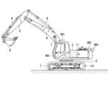
最初に、図1を参照し、本発明の実施例に係る建設機械としてのショベル(掘削機)について説明する。なお、図1は、本発明の実施例に係るショベルの側面図である。図1に示すショベルの下部走行体1には旋回機構2を介して上部旋回体3が搭載される。上部旋回体3にはブーム4が取り付けられる。ブーム4の先端にはアーム5が取り付けられ、アーム5の先端にはバケット6が取り付けられる。作業要素としてのブーム4、アーム5、及びバケット6は、アタッチメントの一例である掘削アタッチメントを構成する。なお、アタッチメントは、床堀アタッチメント、均しアタッチメント、浚渫アタッチメント等の他のアタッチメントであってもよい。また、ブーム4、アーム5、及びバケット6は、ブームシリンダ7、アームシリンダ8、及びバケットシリンダ9によりそれぞれ油圧駆動される。また、上部旋回体3にはキャビン10が設けられ、エンジン11等の動力源が搭載される。また、上部旋回体3には通信装置M1、測位装置M2、姿勢検出装置M3、及び撮像装置M4が取り付けられる。 First, with reference to FIG. 1, a shovel (excavator) as a construction machine according to an embodiment of the present invention will be described. Note that FIG. 1 is a side view of an excavator according to an embodiment of the present invention. An upper rotating
通信装置M1は、ショベルと外部との間の通信を制御する装置である。本実施例では、通信装置M1は、GNSS(Global Navigation Satellite System)測量システムとショベルとの間の無線通信を制御する。具体的には、通信装置M1は、例えば1日1回の頻度で、ショベルの作業を開始する際に作業現場の地形情報を取得する。GNSS測量システムは、例えばネットワーク型RTK-GNSS測位方式を採用する。 The communication device M1 is a device that controls communication between the excavator and the outside. In this embodiment, the communication device M1 controls wireless communication between a GNSS (Global Navigation Satellite System) surveying system and an excavator. Specifically, the communication device M1 acquires topographical information of the work site, for example, once a day when starting work with the shovel. The GNSS surveying system employs, for example, a network type RTK-GNSS positioning method.
測位装置M2は、ショベルの位置及び向きを測定する装置である。本実施例では、測位装置M2は、電子コンパスを組み込んだGNSS受信機であり、ショベルの存在位置の緯度、経度、高度を測定し、且つ、ショベルの向きを測定する。ショベルの向きは、例えば、上部旋回体3の向き及びアタッチメントの向きに対応し、下部走行体1の向きとは無関係である。なお、下部走行体1は、操作装置26(図3参照。)の1つである走行レバーの傾倒方向に応じて前進或いは後進する。そして、走行用油圧モータ1A(左用)、走行用油圧モータ1B(右用、不可視)が配置される側(図1では右側)が下部走行体1の後方に相当する。 The positioning device M2 is a device that measures the position and orientation of the shovel. In this embodiment, the positioning device M2 is a GNSS receiver incorporating an electronic compass, and measures the latitude, longitude, and altitude of the location of the shovel, as well as the direction of the shovel. The orientation of the shovel corresponds to, for example, the orientation of the revolving
姿勢検出装置M3は、アタッチメントの姿勢を検出する装置である。本実施例では、姿勢検出装置M3は、掘削アタッチメントの姿勢を検出する装置である。 The attitude detection device M3 is a device that detects the attitude of the attachment. In this embodiment, the attitude detection device M3 is a device that detects the attitude of the excavation attachment.
撮像装置M4はショベルの周辺の画像を取得する装置である。本実施例では、撮像装置M4は、ショベルの上部旋回体3に取り付けられるカメラであり、撮像した画像に基づいてショベルの周囲の地面までの距離を認識して作業現場の地形情報を取得する。なお、撮像装置M4はステレオカメラ、距離画像カメラ、3次元レーザスキャナ等であってもよい。 The imaging device M4 is a device that captures images around the excavator. In this embodiment, the imaging device M4 is a camera attached to the upper revolving
図2は、図1のショベルに搭載される姿勢検出装置M3を構成する各種センサの出力内容の一例を示すショベルの側面図である。具体的には、姿勢検出装置M3は、ブーム角度センサM3a、アーム角度センサM3b、バケット角度センサM3c、及び車体傾斜センサM3dを含む。 FIG. 2 is a side view of the excavator showing an example of output contents of various sensors forming the attitude detection device M3 mounted on the excavator of FIG. Specifically, the attitude detection device M3 includes a boom angle sensor M3a, an arm angle sensor M3b, a bucket angle sensor M3c, and a vehicle body tilt sensor M3d.
ブーム角度センサM3aは、ブーム角度θ1を取得するセンサであり、例えば、ブームフートピンの回転角度を検出する回転角度センサ、ブームシリンダ7のストローク量を検出するストロークセンサ、ブーム4の傾斜角度を検出する傾斜(加速度)センサ等を含む。ブーム角度θ1は、XZ平面において、ブームフートピン位置P1とアーム連結ピン位置P2とを結ぶ線分の水平線に対する角度である。 The boom angle sensor M3a is a sensor that obtains the boom angle θ1, and includes, for example, a rotation angle sensor that detects the rotation angle of the boom foot pin, a stroke sensor that detects the stroke amount of the
アーム角度センサM3bは、アーム角度θ2を取得するセンサであり、例えば、アーム連結ピンの回転角度を検出する回転角度センサ、アームシリンダ8のストローク量を検出するストロークセンサ、アーム5の傾斜角度を検出する傾斜(加速度)センサ等を含む。アーム角度θ2は、XZ平面において、アーム連結ピン位置P2とバケット連結ピン位置P3とを結ぶ線分の水平線に対する角度である。 The arm angle sensor M3b is a sensor that acquires the arm angle θ2, and includes, for example, a rotation angle sensor that detects the rotation angle of the arm connecting pin, a stroke sensor that detects the stroke amount of the
バケット角度センサM3cは、バケット角度θ3を取得するセンサであり、例えば、バケット連結ピンの回転角度を検出する回転角度センサ、バケットシリンダ9のストローク量を検出するストロークセンサ、バケット6の傾斜角度を検出する傾斜(加速度)センサ等を含む。バケット角度θ3は、XZ平面において、バケット連結ピン位置P3とバケット爪先位置P4とを結ぶ線分の水平線に対する角度である。 The bucket angle sensor M3c is a sensor that acquires the bucket angle θ3, and includes, for example, a rotation angle sensor that detects the rotation angle of the bucket connecting pin, a stroke sensor that detects the stroke amount of the
車体傾斜センサM3dは、ショベルのY軸回りの傾斜角θ4、及び、ショベルのX軸回りの傾斜角θ5(図示せず。)を取得するセンサであり、例えば2軸傾斜(加速度)センサ等を含む。なお、図2のXY平面は水平面である。 The vehicle body inclination sensor M3d is a sensor that obtains the inclination angle θ4 around the Y axis of the excavator and the inclination angle θ5 (not shown) around the X axis of the excavator, and is, for example, a two-axis inclination (acceleration) sensor. include. Note that the XY plane in FIG. 2 is a horizontal plane.
図3は、図1のショベルに搭載される駆動系の構成例を示す図であり、機械的動力伝達ライン、高圧油圧ライン、パイロットライン、電気制御ライン、及び電力ラインをそれぞれ二重線、実線、破線、点線、及び一点鎖線で示す。 FIG. 3 is a diagram showing an example of the configuration of the drive system installed in the excavator of FIG. , indicated by dashed lines, dotted lines, and dash-dotted lines.
ショベルの駆動系は、主に、エンジン11、発電機12、メインポンプ14L、14R、パイロットポンプ15、コントロールバルブ17、操作装置26、操作内容検出装置29、コントローラ30、バッテリ70、電装品72、給電装置74、及び表示装置76を含む。 The drive system of the excavator mainly includes an
エンジン11は、例えば、所定の回転数を維持するように動作するディーゼルエンジンである。また、エンジン11の出力軸は、発電機12、メインポンプ14L、14R及びパイロットポンプ15のそれぞれの入力軸に接続される。
発電機12は、エンジン11の駆動力を利用して回転することで発電する装置であり、コントローラ30、バッテリ70、電装品72、給電装置74、表示装置76等に電気エネルギを供給する。 The
メインポンプ14L、14Rは、高圧油圧ラインを介して作動油をコントロールバルブ17に供給するための装置であり、例えば斜板式可変容量型油圧ポンプである。 The
パイロットポンプ15は、パイロットライン25を介して操作装置26等の各種油圧制御機器に作動油を供給するための装置であり、例えば固定容量型油圧ポンプである。 The
コントロールバルブ17は、ショベルにおける油圧系を制御する油圧制御装置である。具体的には、コントロールバルブ17は、メインポンプ14L、14Rが吐出する作動油の流れを制御する流量制御弁171~176を含む。そして、コントロールバルブ17は、流量制御弁171~176を通じ、ブームシリンダ7、アームシリンダ8、バケットシリンダ9、走行用油圧モータ1A(左用)、走行用油圧モータ1B(右用)、及び旋回用油圧モータ2Aのうちの1又は複数のものに対しメインポンプ14L、14Rが吐出する作動油を選択的に供給する。なお、以下では、ブームシリンダ7、アームシリンダ8、バケットシリンダ9、走行用油圧モータ1A(左用)、走行用油圧モータ1B(右用)、及び旋回用油圧モータ2Aを集合的に「油圧アクチュエータ」と称する。 The
操作装置26は、操作者が油圧アクチュエータの操作のために用いる装置である。本実施例では、操作装置26は、パイロットライン25を通じ、パイロットポンプ15が吐出する作動油を油圧アクチュエータのそれぞれに対応する流量制御弁のパイロットポートに供給する。なお、パイロットポートのそれぞれに供給される作動油の圧力(パイロット圧)は、油圧アクチュエータのそれぞれに対応する操作装置26のレバー又はペダル(図示せず。)の操作方向及び操作量に応じた圧力である。 The operating
操作内容検出装置29は、操作装置26を用いた操作者の操作内容を検出する装置である。本実施例では、操作内容検出装置29は、油圧アクチュエータのそれぞれに対応する操作装置26のレバー又はペダルの操作方向及び操作量を圧力の形で検出し、検出した値をコントローラ30に対して出力する。なお、操作装置26の操作内容は、ポテンショメータ等、圧力センサ以外の他のセンサの出力を用いて導き出されてもよい。 The operation
コントローラ30は、ショベルを制御するための制御装置であり、例えば、CPU、RAM、不揮発性メモリ等を備えたコンピュータで構成される。また、コントローラ30は、各種機能要素に対応するプログラムをROMから読み出してRAMにロードし、各種機能要素に対応する処理をCPUに実行させる。 The
バッテリ70は電気エネルギを蓄える装置であり、例えば、発電機12で発電した電力で充電される。また、バッテリ70の電気エネルギは、コントローラ30、電装品72、給電装置74、表示装置76等に供給される。 The
電装品72は、ショベルに搭載される電気負荷であり、例えば、音声出力装置、照明装置等を含む。 The
給電装置74は、外部電気機器に電気エネルギを供給するための装置であり、例えば、外部電気機器の差込プラグを受け入れるプラグ受けを含む。外部電気機器は空撮用マルチコプタ(ドローン)を含む。例えば、操作者は、空撮用マルチコプタのバッテリから延びる電源ケーブルの差込プラグを給電装置74のプラグ受けに差し込むことで空撮用マルチコプタのバッテリを充電できる。 The
表示装置76は、各種情報を表示する装置であり、例えば、キャビン10内に設置される車載ディスプレイである。本実施例では、表示装置76は撮像装置M4に接続され、撮像装置M4が取得したショベル周辺の画像を表示できる。 The
エンジン11によって駆動されるメインポンプ14L、14Rは、センターバイパス管路40L、40Rのそれぞれを経て作動油タンクまで作動油を循環させる。 Main pumps 14L and 14R driven by
センターバイパス管路40Lは、コントロールバルブ17内に配置された流量制御弁171、173、及び175を通る高圧油圧ラインである。また、センターバイパス管路40Rは、コントロールバルブ17内に配置された流量制御弁172、174、及び176を通る高圧油圧ラインである。 The
流量制御弁171、172、173は、走行用油圧モータ1A(左用)、走行用油圧モータ1B(右用)、旋回用油圧モータ2Aに流出入する作動油の流量及び流れ方向を制御するスプール弁である。 The
また、流量制御弁174、175、176は、バケットシリンダ9、アームシリンダ8、ブームシリンダ7に流出入する作動油の流量及び流れ方向を制御するスプール弁である。なお、本実施例では、流量制御弁175の内部に再生油路175a(図6A参照。)が形成される。また、流量制御弁175と作動油タンクとの間には再生解除弁50が取り付けられる。 Further, the flow
次に、図4を参照してコントローラ30の機能について説明する。なお、図4は、コントローラ30の構成例を示す機能ブロック図である。本実施例では、コントローラ30は、通信装置M1、測位装置M2、姿勢検出装置M3、撮像装置M4の出力を受けて各種演算を実行し、その演算結果に応じた制御指令を制御対象(例えば、エンジン11、メインポンプ14L、14R、コントロールバルブ17、再生解除弁50等である。)に対して出力する。 Next, the functions of the
具体的には、コントローラ30は、主に、地形データベース更新部31、位置座標更新部32、地面形状情報取得部33、及び掘削制御部34を含む。 Specifically, the
地形データベース更新部31は、作業現場の地形情報を参照可能に体系的に記憶する地形データベースを更新する機能要素である。本実施例では、地形データベース更新部31は、例えばショベルの起動時に通信装置M1を通じて作業現場の地形情報を取得して地形データベースを更新する。地形データベースは不揮発性メモリ等に記憶される。また、作業現場の地形情報は、例えば世界測位系に基づく3次元地形モデルで記述される。 The topographical
また、地形データベース更新部31は撮像装置M4の出力を利用して地形データベースを更新してもよい。この場合、撮像装置M4はショベルから独立していてもよい。また、コントローラ30は通信装置M1を介して撮像装置M4が出力する地形情報を取得してもよい。具体的には、撮像装置M4は、空撮用マルチコプタ、作業現場に設置された鉄塔等に取り付けられ、作業現場を上から見た画像に基づいて作業現場の地形情報を取得してもよい。また、撮像装置M4は、空撮用マルチコプタに取り付けられた場合、1時間に1回程度の頻度で或いはリアルタイムで、作業現場を上から見た画像を撮像して作業現場の地形情報を取得してもよい。 Furthermore, the terrain
また、地形データベース更新部31は、例えば、1日1回の頻度で通信装置M1を通じて作業現場の地形情報を取得し、且つ、1時間に1回の頻度で或いはリアルタイムで撮像装置M4を通じて作業現場の地形情報を取得して地形データベースを更新してもよい。 Furthermore, the terrain
また、地形データベース更新部31は、通信装置M1を通じて取得した地形情報と撮像装置M4を通じて取得した地形情報とを併用する場合、通信装置M1を通じて取得した地形情報を補正するために、撮像装置M4を通じて取得した地形情報を用いてもよい。この場合、地形データベース更新部31は、通信装置M1が地形情報を取得する周期(間隔)よりも長い周期(間隔)で地形情報を補正してもよい。 In addition, when using the topographical information acquired through the communication device M1 and the topographical information acquired through the imaging device M4 together, the topographical
位置座標更新部32は、ショベルの現在位置を表す座標及び向きを更新する機能要素である。本実施例では、位置座標更新部32は、測位装置M2の出力に基づいて世界測位系におけるショベルの位置座標及び向きを取得し、不揮発性メモリ等に記憶されるショベルの現在位置を表す座標及び向きに関するデータを更新する。 The position coordinate updating
また、位置座標更新部32は、地形データベース更新部31の場合と同様、撮像装置M4の出力を利用してショベルの現在位置を表す座標及び向きを更新してもよい。この場合、位置座標更新部32は、測位装置M2の出力と撮像装置M4の出力を併用してショベルの現在位置を表す座標及び向きに関するデータをリアルタイムで更新してもよい。また、位置座標更新部32は、撮像装置M4の出力のみに基づいてショベルの現在位置を表す座標及び向きに関するデータをリアルタイムで更新してもよい。 Further, as in the case of the terrain
地面形状情報取得部33は、作業対象の地面の現在の形状に関する情報を取得する機能要素である。本実施例では、地面形状情報取得部33は、地形データベース更新部31が更新した地形情報と、位置座標更新部32が更新したショベルの現在位置を表す座標及び向きと、姿勢検出装置M3が検出した掘削アタッチメントの姿勢の過去の推移とに基づいて掘削対象地面の現在の形状に関する情報を取得する。 The ground shape
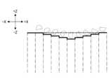
図5は、地面形状情報取得部33が取得する掘削対象地面の現在の形状に関する情報の概念図である。なお、図5の破線で示す複数のバケット形状は、前回の掘削動作の際のバケット6の軌跡を表す。バケット6の軌跡は、姿勢検出装置M3が過去に検出した掘削アタッチメントの姿勢の推移から導き出される。また、図5の太実線は、地面形状情報取得部33が把握している掘削対象地面の現在の断面形状を表し、太点線は、地面形状情報取得部33が把握している前回の掘削動作が行われる前の掘削対象地面の断面形状を表す。すなわち、地面形状情報取得部33は、前回の掘削動作が行われる前の掘削対象地面の形状から、前回の掘削動作の際にバケット6が通過した空間に対応する部分を取り除くことで掘削対象地面の現在の形状を導き出す。また、図5の一点鎖線で示すZ軸方向に伸びる各ブロックは3次元地形モデルの各要素を表す。各要素は例えばXY平面に平行な単位面積の上面と-Z方向に無限大の長さを有するモデルで表現される。なお、3次元地形モデルは3次元メッシュモデルで表現されてもよい。 FIG. 5 is a conceptual diagram of information regarding the current shape of the ground to be excavated, which is acquired by the ground shape
掘削制御部34は、掘削アタッチメントを制御する機能要素である。本実施例では、掘削制御部34は、地面形状情報取得部33が取得した掘削対象地面の現在の形状に関する情報に基づいて掘削アタッチメントを制御する。 The
具体的には、掘削制御部34は、姿勢検出装置M3が検出する掘削アタッチメントの現在の姿勢と、地面形状情報取得部33が取得した掘削対象地面の現在の形状に関する情報(前回の掘削動作の際の姿勢情報より算出される情報)とに基づいて掘削状態を判断する。例えば、掘削制御部34は、バケット6の爪先が掘削対象地面に接触しているかを判定する。そして、バケット6の爪先が掘削対象地面に接触していると判定した場合、制御モードを「地表面モード」から「地中モード」へ切り替える。特に、掘削アタッチメント(バケット6の爪先)が地表面よりも上に存在する場合にアーム5を閉じるときにはアームシリンダ8のロッド側油室をボトム側油室よりも高圧にして自重落下させることが望ましい。また、地面接触後の掘削作業では、掘削のためにアームシリンダ8のボトム側油室をロッド側油室よりも高圧にする必要がある。このため、掘削制御部34は、スムーズに掘削を開始すべく、バケット6が掘削対象地面に接触しているかを正確に判定した上でメインポンプ14L、14Rが吐出する高圧の作動油をアームシリンダ8のボトム側油室へ供給する。そして、制御対象が例えば再生解除弁50の場合には、掘削制御部34は、バケット6の爪先が掘削対象地面に接触する際に、再生解除弁50に対して制御指令を出力してその開口面積を増大させる。なお、「接触する際」は「接触する直前」を含み、掘削制御部34は、好ましくは、バケット6の爪先が掘削対象地面に接触する直前に再生解除弁50に対して制御指令を出力してその開口面積を増大させる。さらに、予め入力された土砂密度情報に基づいて掘削アタッチメントを制御してもよい。例えば、土砂密度が大きいほど開口面積が大きくなるようにしてもよい。 Specifically, the
また、掘削制御部34はエンジン11、メインポンプ14L、14R等を制御対象としてもよい。この場合、バケット6が掘削対象地面に接触していると判定したときに制御モードを「地表面モード」から「地中モード」へと切り替える。そして、エンジン11の回転数指令を上昇させ、或いは、メインポンプ14L、14Rの斜板の傾転角を変更する等して掘削アタッチメントの出力馬力を増大させる。その結果、「地中モード」で作業する際に掘削アタッチメントの駆動力を増大させることができる。また、「地表面モード」の際にはその出力馬力を低減させて燃費を向上させることができる。 Further, the
掘削制御部34は、上述の各制御対象の制御を単独で実行してもよく、組み合わせて実行してもよい。また、この制御は掘削対象地面の現在の形状が目標形状になるまで実行されてもよい。例えば、掘削対象地面の深さが予め設定された目標面の深さに到達するまで実行されてもよい。なお、掘削対象地面の深さが目標面の深さに到達すると、それより深い掘削は制限されてもよい。 The
図6A~図6Cは、再生油路175a及び再生解除弁50の構成例を示す図である。具体的には、図6Aは、図3に示すコントロールバルブ17における流量制御弁175及び再生解除弁50を含む部分の拡大図である。また、図6Bはアーム閉じ操作時に再生解除弁50の開口面積を最小としたときの作動油の流れを示し、図6Cはアーム閉じ操作時に再生解除弁50の開口面積を最大としたときの作動油の流れを示す。 6A to 6C are diagrams showing configuration examples of the
再生油路175aは、アーム閉じ操作時に収縮側油室であるアームシリンダ8のロッド側油室から流出する作動油を伸張側油室であるボトム側油室に流入(再生)させる油路である。また、再生油路175aは、ボトム側油室からロッド側油室への作動油の流れを防止する逆止弁を含む。なお、再生油路175aは、流量制御弁175の外部に形成されてもよい。 The
再生解除弁50は、アームシリンダ8のロッド側油室から流出して作動油タンクに流れる作動油の流量を調整する弁である。本実施例では、再生解除弁50は、コントローラ30からの制御指令に応じて動作する電磁弁であり、流量制御弁175と作動油タンクとの間の油路50aの流路面積を増減させて油路50a及び再生油路175aのそれぞれを流れる作動油の流量を調整する。 The
具体的には、再生解除弁50は、図6Bに示すように、コントローラ30からの制御指令に応じてその開口面積を低減させて油路50aを流れる作動油の流量を低減させ且つ再生油路175aを流れる作動油の流量を増大させる。この構成により、再生解除弁50は、掘削アタッチメントを空中で動作させる場合にアーム5がその自重によって落下するのを防止できる。 Specifically, as shown in FIG. 6B, the
また、再生解除弁50は、図6Cに示すように、コントローラ30からの制御指令に応じてその開口面積を増大させて油路50aを流れる作動油の流量を増大させ且つ再生油路175aを流れる作動油の流量を低減或いは消失させる。この構成により、再生解除弁50は、掘削中であるにもかかわらず、すなわち掘削アタッチメントが地面に接触しているにもかかわらず、油路50aで無駄な圧力損失を発生させて掘削力を低減させてしまうのを防止できる。 Further, as shown in FIG. 6C, the
なお、再生解除弁50は、アームシリンダ8のロッド側油室と流量制御弁175との間に設置されてもよい。 Note that the
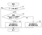
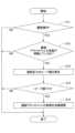
次に、図7を参照し、コントローラ30が再生解除弁50の開口面積を調整する処理(以下、「開口面積調整処理」とする。)について説明する。なお、図7は、開口面積調整処理の流れを示すフローチャートである。コントローラ30は、ショベル稼働中、所定の制御周期で繰り返しこの開口面積調整処理を実行する。 Next, with reference to FIG. 7, a process in which the
最初に、コントローラ30は、アーム閉じ操作が行われたかを判定する(ステップS1)。本実施例では、コントローラ30は、操作内容検出装置29の出力に基づいてアーム操作レバーが閉じ方向に操作されたかを判定する。 First, the
アーム閉じ操作が行われていないと判定した場合(ステップS1のNO)、コントローラ30は今回の開口面積調整処理を終了させる。 If it is determined that the arm closing operation has not been performed (NO in step S1), the
アーム閉じ操作が行われたと判定した場合(ステップS1のYES)、コントローラ30は、掘削アタッチメントと地面が接触しているかを判定する(ステップS2)。本実施例では、コントローラ30は、姿勢検出装置M3の出力から導き出されるバケット6の爪先の現在位置と、地面形状情報取得部33が取得した掘削対象地面の現在の形状に関する情報とに基づいてバケット6の爪先が地面に接触しているか否かを判定する。 If it is determined that the arm closing operation has been performed (YES in step S1), the
そして、掘削アタッチメントと地面が接触していると判定した場合(ステップS2のYES)、コントローラ30は、必要に応じて再生解除弁50の開口面積を増大させる(ステップS3)。本実施例では、コントローラ30は、バケット6の爪先が地面に接触していると判定した場合、再生解除弁50の開口面積が所定値未満であれば、その開口面積を所定値まで増大させる。 If it is determined that the excavation attachment is in contact with the ground (YES in step S2), the
一方、掘削アタッチメントと地面が接触していないと判定した場合(ステップS2のNO)、コントローラ30は、必要に応じて再生解除弁50の開口面積を低減させる(ステップS4)。本実施例では、コントローラ30は、バケット6の爪先が地面に接触していないと判定した場合、再生解除弁50の開口面積が所定値より大きければ、再生解除弁50の開口面積を所定値まで低減させる。 On the other hand, if it is determined that the excavation attachment is not in contact with the ground (NO in step S2), the
次に、図8を参照し、コントローラ30が再生解除弁50の開口面積を調整する際の各種パラメータの時間的推移について説明する。なお、図8(A)はアームシリンダ8のロッド側油室の圧力の時間的推移を表す。また、図8(B)は地面接触フラグの時間的推移を表し、図8(C)は再生解除弁50の開口面積の時間的推移を表す。なお、図8(A)~図8(C)のそれぞれの時間軸(横軸)は共通である。また、地面接触フラグは、コントローラ30による掘削アタッチメントと地面との接触の有無の判定結果を表す。具体的には、地面接触フラグの値「OFF」は、コントローラ30により「接触無し」と判定されている状態を表し、地面接触フラグの値「ON」は、コントローラ30により「接触あり」と判定されている状態を表す。また、図8の実線で示す推移は、実際の接触と「接触あり」の判定が同時に行われた場合の推移を表す。一方で、図8の破線で示す推移は、「接触あり」の判定が実際の接触よりも前に行われた場合の推移を表し、図8の一点鎖線で示す推移は、「接触あり」の判定が実際の接触よりも後に行われた場合の推移を表す。 Next, with reference to FIG. 8, a description will be given of changes over time of various parameters when the
具体的には、「接触あり」の判定が実際の接触よりも前に行われた場合、地面接触フラグは、図8(B)の破線で示すように、時刻t1において値「OFF」から値「ON」に切り替えられる。なお、本実施例では実際の接触は時刻t2において発生する。そして、地面接触フラグを値「ON」に切り替えると、コントローラ30は、再生解除弁50の開口面積を増大させる。そのため、再生解除弁50の開口面積は、図8(C)の破線で示すように、時刻t1において値Anから値Aw(>An)に調整される。なお、値Anはアーム5を空中で動作させる際に最適な値として予め設定される開口面積であり、値Awは掘削中にアーム5を動作させる際に最適な値として予め設定される開口面積である。その結果、アームシリンダ8のロッド側油室の圧力は、図8(A)の破線で示すように、時刻t1において減少し始め、実際の接触が起こるまで減少し続ける。アーム5が自重で落下するためである。そして、時刻t2において実際の接触が起こった後に(時刻t2と時刻t3の間で)増加に転じ、その後は作業反力としての掘削反力に応じた値まで増大する。 Specifically, if the determination of "contact" is made before actual contact, the ground contact flag changes from the value "OFF" to the value at time t1, as shown by the broken line in FIG. 8(B). It can be switched to “ON”. Note that in this embodiment, actual contact occurs at time t2. Then, when the ground contact flag is switched to the value "ON", the
このように、コントローラ30は、「接触あり」の判定を実際の接触よりも前に行うと、アームシリンダ8のロッド側油室の圧力を一時的に急減させてしまうため、キャビテーションを発生させるおそれがある。 In this way, if the
一方で、「接触あり」の判定が実際の接触よりも後に行われた場合、実際の接触が起こる時刻t2では再生解除弁50の開口面積は小さいままであるため、ロッド側油室の圧力は上昇してしまう。そして、地面接触フラグは、図8(B)の一点鎖線で示すように、時刻t3において値「OFF」から値「ON」に切り替えられる。そのため、再生解除弁50の開口面積は、図8(C)の一点鎖線で示すように、時刻t3において値Anから値Awに調整される。その結果、アームシリンダ8のロッド側油室の圧力は、図8(A)の一点鎖線で示すように、実際の接触が起こる時刻t2で増加し始め、時刻t3において再生解除弁50の開口面積が値Awに増大されるまで増加し続ける。掘削反力と再生解除弁50での圧力損失とによる影響を受けるためである。そして、時刻t3において再生解除弁50の開口面積が値Awに増大されると減少に転じ、その後は掘削反力に応じた値まで減少する。 On the other hand, if the determination of "contact" is made after the actual contact, the opening area of the
このように、コントローラ30は、「接触あり」の判定を実際の接触よりも後に行うと、アームシリンダ8のロッド側油室の圧力を一時的に増加させてしまうため、掘削アタッチメントの動きを不安定にし、且つ、作業効率を低下させてしまう。 In this way, if the
そこで、コントローラ30は、姿勢検出装置M3が検出する掘削アタッチメントの現在の姿勢と、地面形状情報取得部33が取得した掘削対象地面の現在の形状に関する情報とに基づいて掘削アタッチメントが掘削対象地面に接触しているかを判定する。「接触あり」の判定を実際の接触と同時に行うためである。 Therefore, the
「接触あり」の判定が実際の接触と同時に行われた場合、地面接触フラグは、図8(B)の実線で示すように、時刻t2において値「OFF」から値「ON」に切り替えられる。そのため、再生解除弁50の開口面積は、図8(C)の実線で示すように、時刻t2において値Anから値Awに調整される。その結果、アームシリンダ8のロッド側油室の圧力は、図8(A)の実線で示すように、実際の接触が起こる時刻t2で減少し始め、その後は掘削反力に応じた値まで減少する。実際の接触が起こる前に一時的に急減することはなく、実際の接触が起こった後で再生解除弁50での圧力損失による影響を受けて増加することもない。 If the determination of "contact" is made at the same time as actual contact, the ground contact flag is switched from the value "OFF" to the value "ON" at time t2, as shown by the solid line in FIG. 8(B). Therefore, the opening area of the
以上の構成により、コントローラ30は、姿勢検出装置M3が検出したアタッチメントの姿勢の推移に基づいて作業対象の地面の現在の形状に関する情報を取得する。そして、取得した作業対象の地面の現在の形状に関する情報に基づいてアタッチメントを制御する。本実施例では、コントローラ30は、掘削アタッチメントの現在の姿勢と掘削対象地面の現在の形状とに基づいて再生解除弁50の開口面積を調整する。具体的には、バケット6の爪先の現在位置と掘削対象地面の現在の形状とに基づいて再生解除弁50の開口面積を調整する。そのため、バケット6の爪先が掘削対象地面に接触すると同時に、アームシリンダ8のロッド側油室から作動油タンクに流出する作動油の再生解除弁50での圧力損失を低減或いは消失させることができる。その結果、コントローラ30は、アームシリンダ圧の変化等に基づいてバケット6の爪先と掘削対象地面との接触の有無を判定する場合に比べ、より正確に接触の有無を判定でき、誤判定を抑制できる。また、接触の有無の誤判定を抑制することで操作性及び作業効率を向上できる。具体的には、バケット6の爪先が地面に接触するのと同時に、アーム5の自重落下の防止のために再生解除弁50のところで発生させていた圧力損失を低減或いは消失させることができ、圧力損失分だけ掘削に要する力が増大してしまうのを防止できる。また、地面との接触の前にアーム5が自重落下してしまうのを防止でき、キャビテーションの発生を防止できる。 With the above configuration, the
なお、コントローラ30は、アームシリンダ8に関する再生解除弁50の開口面積を調整するのと同様に、ブームシリンダ7に関する再生解除弁(図示せず。)の開口面積を調整してもよく、バケットシリンダ9に関する再生解除弁(図示せず。)の開口面積を調整してもよい。 Note that the
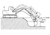
次に、図9~図11を参照し、コントローラ30の掘削制御部34による掘削アタッチメント制御の別の例について説明する。なお、図9は、掘削対象地面の深さと基準面との関係を示す図である。基準面は、掘削対象地面の深さを定める基準となる平面である。本実施例では、基準面はショベルの中心点Rが位置する水平面であり、中心点Rはショベルの旋回軸と下部走行体1の接地面との交点である。 Next, another example of excavation attachment control by the
具体的には、図9の一点鎖線で示す掘削アタッチメントは、一点鎖線で示す基準面と同じ深さの掘削対象地面を掘削する際の掘削アタッチメントの姿勢を表す。この場合、掘削対象地面の深さDは基準面の深さD0(=0)と同じである。なお、掘削対象地面の深さDは、地面形状情報取得部33が取得した掘削対象地面の現在の形状に関する情報(前回の掘削動作の際の姿勢情報から算出される情報)に基づいて導き出される。また、掘削対象地面の深さDは、姿勢検出装置M3が検出した掘削アタッチメントの現在の姿勢に基づいて導き出されてもよい。 Specifically, the excavation attachment shown by the dashed-dotted line in FIG. 9 represents the attitude of the excavation attachment when excavating the ground to be excavated at the same depth as the reference plane shown by the dashed-dotted line. In this case, the depth D of the ground to be excavated is the same as the depth D0 (=0) of the reference surface. Note that the depth D of the ground to be excavated is derived based on information regarding the current shape of the ground to be excavated acquired by the ground shape information acquisition unit 33 (information calculated from posture information during the previous excavation operation). . Further, the depth D of the ground to be excavated may be derived based on the current attitude of the excavation attachment detected by the attitude detection device M3.
また、図9の破線で示す掘削アタッチメントは、破線で示す掘削対象地面を掘削する際の掘削アタッチメントの姿勢を表す。この場合、掘削対象地面の深さDは深さD1(>D0)で表される。 Moreover, the excavation attachment shown by the broken line in FIG. 9 represents the attitude of the excavation attachment when excavating the ground to be excavated shown by the broken line. In this case, the depth D of the ground to be excavated is represented by depth D1 (>D0).
また、図9の実線で示す掘削アタッチメントは、実線で示す掘削対象地面を掘削する際の掘削アタッチメントの姿勢を表す。この場合、掘削対象地面の深さDは深さD2(>D1)で表される。 Moreover, the excavation attachment shown by the solid line in FIG. 9 represents the attitude of the excavation attachment when excavating the ground to be excavated, which is shown by the solid line. In this case, the depth D of the ground to be excavated is represented by depth D2 (>D1).
なお、掘削対象地面は基準面よりも高い位置にあってもよい。この場合、掘削対象地面の深さDは負の値で表されてもよい。 Note that the ground to be excavated may be located at a higher position than the reference plane. In this case, the depth D of the ground to be excavated may be expressed as a negative value.
図10は、バケット角度θ3と掘削反力Fと掘削対象地面の深さDとの関係を示す図である。具体的には、図10(A)は、バケット6をバケット角度30°からバケット角度180°まで閉じる際のバケット6の姿勢の推移を示す。なお、図10(A)の破線で示すバケット6はバケット角度30°のときの姿勢を表し、図10(A)の実線で示すバケット6はバケット角度180°のときの姿勢を表す。 FIG. 10 is a diagram showing the relationship between the bucket angle θ3, the excavation reaction force F, and the depth D of the ground to be excavated. Specifically, FIG. 10(A) shows the transition of the attitude of the
図10(B)は、掘削対象地面の深さDと所定のバケット閉じ操作が行われる場合の掘削反力Fの推移又はピーク値との対応関係を予め記憶する対応テーブルの内容の一例を示す。具体的には、図10(B)は、バケット角度30°からバケット角度180°までバケット6を閉じる際のバケット角度θ3に対する掘削反力Fの推移を示す。なお、対応テーブルは、実測データの分析に基づいて生成されるデータテーブルであり、例えば不揮発性メモリに予め登録されている。 FIG. 10(B) shows an example of the contents of a correspondence table that stores in advance the correspondence between the depth D of the ground to be excavated and the transition or peak value of the excavation reaction force F when a predetermined bucket closing operation is performed. . Specifically, FIG. 10(B) shows the transition of the excavation reaction force F with respect to the bucket angle θ3 when the
また、図10(C)はバケット角度θ3の時間的推移を示し、図10(D)は図10(B)の対応テーブルを用いて算出される掘削反力Fの時間的推移を示す。なお、図10(C)及び図10(D)のそれぞれの時間軸(横軸)は共通である。 Moreover, FIG. 10(C) shows the temporal transition of the bucket angle θ3, and FIG. 10(D) shows the temporal transition of the excavation reaction force F calculated using the correspondence table of FIG. 10(B). Note that the time axes (horizontal axes) of FIGS. 10(C) and 10(D) are common.
また、図10(B)及び図10(D)の一点鎖線で示す推移は、掘削対象地面の深さDが深さD0のときの推移を表す。また、破線で示す推移は、掘削対象地面の深さDが深さD1のときの推移を表し、実線で示す推移は、掘削対象地面の深さDが深さD2のときの推移を表す。 Further, the transition shown by the dashed line in FIGS. 10(B) and 10(D) represents the transition when the depth D of the ground to be excavated is the depth D0. Moreover, the transition shown by the broken line represents the transition when the depth D of the ground to be excavated is the depth D1, and the transition shown by the solid line is the transition when the depth D of the ground to be excavated is the depth D2.
図10(A)及び図10(C)に示すようなバケット角度30°から180°までのバケット閉じ操作が行われた場合、掘削反力Fは、図10(B)に示すように、バケット角度θ3がある角度(例えば100°)に至るまで増大した後で減少に転じ、バケット角度θ3が180°に達したときにゼロに至る。この傾向は、掘削対象地面の深さDにかかわらず同じである。但し、掘削反力Fのピーク値は、掘削対象地面の深さDの変化に応じて変化する。図10(B)及び図10(D)は、掘削対象地面の深さDが深くなるほど掘削反力Fのピーク値が大きくなる傾向を一例として示す。 When the bucket closing operation is performed at a bucket angle of 30° to 180° as shown in FIGS. 10(A) and 10(C), the excavation reaction force F is After the angle θ3 increases to a certain angle (for example, 100°), it begins to decrease, and reaches zero when the bucket angle θ3 reaches 180°. This tendency is the same regardless of the depth D of the ground to be excavated. However, the peak value of the excavation reaction force F changes according to a change in the depth D of the ground to be excavated. FIGS. 10(B) and 10(D) show, as an example, that the peak value of the excavation reaction force F tends to increase as the depth D of the ground to be excavated increases.
そこで、コントローラ30の掘削制御部34は、地面形状情報取得部33が取得した掘削対象地面の現在の形状に関する情報に基づいて掘削対象地面の現在の深さDを導き出す。そして、掘削制御部34は、掘削対象地面の現在の深さDに応じて、所定のバケット閉じ操作が行われる場合の掘削反力Fのピーク値を推定する。その後、掘削制御部34は、推定した掘削反力Fのピーク値が所定値を上回るかを判定する。そして、上回ると判定した場合には、掘削アタッチメントの動きを制御してそのピーク値が所定値を超えないようにする。掘削反力Fが大きくなり過ぎて掘削アタッチメントの動きが不安定になるのを防止するためである。例えば、掘削制御部34は、操作者によるブーム上げ操作の有無にかかわらず、バケット閉じ動作中にブーム4を自動的に上昇させることで掘削反力Fのピーク値が所定値を超えないようにする。例えば、掘削制御部34は、操作者が気付かない程度の上昇率(単位時間当たりのブーム4の回動角度)でブーム4を自動的に上昇させる。そのため、掘削制御部34は、ブーム4が自動的に上昇したことを操作者に気付かせずに掘削アタッチメントの動きを滑らかにすることができ、操作感を向上させることができる。なお、この場合の掘削制御部34の制御対象は、再生解除弁50ではなく流量制御弁176である。例えば、掘削制御部34は、流量制御弁176のパイロット圧を増減させる電磁弁(図示せず。)に対して制御指令を出力して流量制御弁176を自動的に移動させる。また、この制御は掘削対象地面の現在の形状が目標形状になるまで実行されてもよい。例えば、掘削対象地面の深さが予め設定された目標面の深さに到達するまで実行されてもよい。なお、掘削対象地面の深さが目標面の深さに到達すると、それより深い掘削は制限されてもよい。 Therefore, the
図11は、掘削反力Fのピーク値が所定値を超えないようにコントローラ30が掘削アタッチメントの姿勢を自動的に調整する処理(以下、「姿勢自動調整処理」とする。)の流れを示すフローチャートである。コントローラ30は、ショベル稼働中、所定の制御周期で繰り返しこの姿勢自動調整処理を実行する。 FIG. 11 shows the flow of a process in which the
最初に、コントローラ30は、掘削操作が行われたかを判定する(ステップS11)。本実施例では、コントローラ30は、操作内容検出装置29の出力に基づいてブーム操作、アーム操作、及びバケット操作の少なくとも1つが行われたかを判定する。 First, the
そして、掘削操作が行われたと判定した場合(ステップS11のYES)、コントローラ30は、掘削アタッチメントと地面が接触しているかを判定する(ステップS12)。本実施例では、コントローラ30は、姿勢検出装置M3の出力から導き出されるバケット6の爪先の現在位置と、地面形状情報取得部33が取得した掘削対象地面の現在の形状に関する情報とに基づいてバケット6の爪先が地面に接触しているか否かを判定する。 If it is determined that an excavation operation has been performed (YES in step S11), the
そして、掘削アタッチメントと地面が接触していると判定した場合(ステップS12のYES)、コントローラ30は、掘削反力Fのピーク値を推定する(ステップS13)。本実施例では、コントローラ30は、地面形状情報取得部33が取得した掘削対象地面の現在の形状に関する情報に基づいて掘削対象地面の現在の深さDを導き出す。そして、コントローラ30は、掘削対象地面の現在の深さDに応じて所定のバケット閉じ操作が行われる場合の掘削反力Fのピーク値を推定する。具体的には、コントローラ30は、図10(B)に示すような対応テーブルを参照して掘削対象地面の現在の深さDに対応する掘削反力Fのピーク値を導き出す。また、コントローラ30は、掘削対象地面の現在の深さDに基づいて所定のバケット閉じ操作が行われる場合の掘削反力Fのピーク値をリアルタイムで算出してもよい。また、コントローラ30は、そのピーク値を算出する際に土砂密度等を考慮してもよい。土砂密度は、車載入力装置(図示せず。)を通じて操作者が入力する値であってもよく、シリンダ圧センサ等の各種センサの出力に基づいて自動的に算出される値であってもよい。 If it is determined that the excavation attachment is in contact with the ground (YES in step S12), the
その後、コントローラ30は、推定した掘削反力Fのピーク値が所定値Fthを上回るかを判定する(ステップS14)。 Thereafter, the
そして、ピーク値が所定値Fthを上回ると判定した場合(ステップS14のYES)、コントローラ30は、バケット閉じ動作中に掘削アタッチメントの姿勢を自動的に調整する(ステップS15)。本実施例では、コントローラ30は、操作者によるブーム上げ操作の有無にかかわらず、バケット閉じ動作中にブーム4を自動的に上昇させる。具体的には、バケット角度θ3の変化に応じた所定の動作パターンでブーム4を自動的に上昇させる。 If it is determined that the peak value exceeds the predetermined value Fth (YES in step S14), the
なお、コントローラ30は、掘削操作が行われていないと判定した場合(ステップS11のNO)、掘削アタッチメントと地面が接触していないと判定した場合(ステップS12のNO)、或いは、ピーク値が所定値Fth以下であると判定した場合には(ステップS14のNO)、掘削アタッチメントの姿勢を自動的に調整することなく、今回の姿勢自動調整処理を終了する。 Note that when the
以上の構成により、コントローラ30は、姿勢検出装置M3が検出したアタッチメントの姿勢の推移に基づいて作業対象の地面の現在の形状に関する情報を取得する。そして、取得した作業対象の地面の現在の形状に関する情報に基づいてアタッチメントを制御する。本実施例では、コントローラ30は、バケット閉じ動作中に掘削反力Fのピーク値が所定値Fthを超えないようにすることができる。そのため、掘削反力Fが過度に増大して掘削アタッチメントの動きが不安定になるのを防止し、ショベルの操作性及び作業効率を向上させることができる。また、コントローラ30は、低めに設定された所定値Fthを用いることで、床堀作業、均し作業等の掘削作業以外の作業でも同様の効果を実現できる。 With the above configuration, the
以上、本発明の好ましい実施例について詳説したが、本発明は、上述した実施例に制限されることはなく、本発明の範囲を逸脱することなしに上述した実施例に種々の変形及び置換を加えることができる。 Although the preferred embodiments of the present invention have been described in detail above, the present invention is not limited to the embodiments described above, and various modifications and substitutions can be made to the embodiments described above without departing from the scope of the present invention. can be added.
例えば、上述の実施例では、コントローラ30は、姿勢検出装置M3が検出する掘削アタッチメントの現在の姿勢と、地面形状情報取得部33が取得した掘削対象地面の現在の形状に関する情報とに基づいて掘削アタッチメントが掘削対象地面に接触しているかを判定する。そして、接触していると判定した場合に、再生解除弁50に対して制御指令を出力してその開口面積を増大させる。或いは、接触していると判定した場合に、所定のバケット閉じ動作が行われるときの掘削反力Fのピーク値を推定し、その推定したピーク値が所定値Fthを上回るときに、ブーム4を自動的に上昇させて実際のピーク値が所定値Fth以下となるようにする。しかしながら、本発明はこれらの構成に限定されるものではない。例えば、コントローラ30は、接触していると判定した場合に、アタッチメントの駆動力(例えば掘削アタッチメントによる掘削力)を増大させてもよい。具体的には、コントローラ30は、エンジン11の回転数を増大させたり、メインポンプ14L、14Rの吐出量を増大させたりしてもよい。なお、この場合の掘削制御部34の制御対象は、再生解除弁50ではなく、エンジン11又はメインポンプ14L、14Rのレギュレータである。 For example, in the above embodiment, the
また、コントローラ30は、ショベルのリモート運転又は自動掘削運転(無人運転)の場合であっても、掘削反力Fのピーク値が所定値Fthを上回ると判断したときにブーム4を自動的に上昇させてもよい。掘削反力Fを小さくして円滑な掘削作業を継続させるためである。 In addition, the
また、本願は、2014年6月20日に出願した日本国特許出願2014-127672号に基づく優先権を主張するものであり、この日本国特許出願の全内容を本願に参照により援用する。 Furthermore, this application claims priority based on Japanese patent application No. 2014-127672 filed on June 20, 2014, and the entire contents of this Japanese patent application are incorporated by reference into this application.
1・・・下部走行体 1A・・・走行用油圧モータ(左用) 1B・・・走行用油圧モータ(右用) 2・・・旋回機構 2A・・・旋回用油圧モータ 3・・・上部旋回体 4・・・ブーム 5・・・アーム 6・・・バケット 7・・・ブームシリンダ 8・・・アームシリンダ 9・・・バケットシリンダ 10・・・キャビン 11・・・エンジン 12・・・発電機 14L、14R・・・メインポンプ 15・・・パイロットポンプ 17・・・コントロールバルブ 25・・・パイロットライン 26・・・操作装置 29・・・操作内容検出装置 30・・・コントローラ 31・・・地形データベース更新部 32・・・位置座標更新部 33・・・地面形状情報取得部 34・・・掘削制御部 40L、40R・・・センターバイパス管路 50・・・再生解除弁 50a・・・油路 70・・・バッテリ 72・・・電装品 74・・・給電装置 76・・・表示装置 171~176・・・流量制御弁 175a・・・再生油路 M1・・・通信装置 M2・・・測位装置 M3・・・姿勢検出装置 M3a・・・ブーム角度センサ M3b・・・アーム角度センサ M3c・・・バケット角度センサ M3d・・・車体傾斜センサ M4・・・撮像装置 1...Lower traveling
Claims (13)
Translated fromJapanese前記下部走行体に搭載される上部旋回体と、
前記上部旋回体に取り付けられるアタッチメントと、
前記アタッチメントの姿勢を検出する姿勢検出装置と、
制御装置と、を備えるショベルであって、
前記制御装置は、前回の掘削動作に対応する空間に対し、今回の掘削動作の開始前に撮像装置が出力した情報に基づいてショベルの周囲の地面の形状に関する情報を取得し、前記下部走行体が静止した状態での掘削操作によって行われる今回の掘削動作の際に、前記取得したショベルの周囲の地面の形状に関する情報と前記姿勢検出装置が検出する前記アタッチメントの姿勢とに基づいて前記アタッチメントと地面とが接触しているか否かを判定し、前記アタッチメントと地面とが接触していないと判定しているときに前記アタッチメントを構成するアームの自重落下を防止する、
ショベル。a lower running body;
an upper revolving body mounted on the lower traveling body;
an attachment attached to the upper revolving body;
a posture detection device that detects the posture of the attachment;
An excavator comprising a control device,
The control device acquires information regarding the shape of the ground around the excavator based on the information output by the imaging device before the start of the current excavation operation with respect to the spacecorresponding to the previous excavation operation, andDuring the current excavation operation performed when the excavator is stationary, the attachmentand determining whether or not the attachment is in contact with the ground, and preventing the arm constituting the attachment from falling under its own weight when it is determined that the attachment is not in contact with the ground;
shovel.
請求項1に記載のショベル。The control device acquires the output of the imaging device before starting work.
The excavator according to claim 1.
請求項1又は2に記載のショベル。The control device acquires position information of the upper revolving body.
The excavator according to claim 1 or 2.
請求項1乃至3の何れかに記載のショベル。the imaging device is attached to a multicopter;
A shovel according to any one of claims 1 to 3.
請求項4に記載のショベル。A power supply device configured to supply power to the multicopter is provided.
The excavator according to claim 4.
前記制御装置は前記第2の撮像装置の出力を取得する、
請求項4に記載のショベル。comprising a second imaging device attached to the upper revolving body,
the control device obtains the output of the second imaging device;
The excavator according to claim 4.
請求項1に記載のショベル。The control device derives the depth of the ground to be excavated based on the attitude of the attachment detected by the attitude detection device.
The excavator according to claim 1.
請求項7に記載のショベル。The control device controls the attachment according to the derived depth.
The excavator according to claim 7.
前記制御装置は、前記複数の油圧アクチュエータのうち第1の油圧アクチュエータの動作中に、前記第1の油圧アクチュエータの動作に応じた所定の動作パターンにより第2の油圧アクチュエータを制御する請求項1乃至11の何れかに記載のショベル。The upper revolving body includes a plurality of hydraulic actuators,
The control device controls the second hydraulic actuator according to a predetermined operation pattern according to the operation of the first hydraulic actuator during operation of the first hydraulic actuator among the plurality of hydraulic actuators. 11. The excavator according to any one of 11.
前回の掘削動作に対応する空間に対し、今回の掘削動作の開始前に撮像装置が検出した情報に基づいてショベルの周囲の地面の形状に関する情報を取得する取得ステップと、
前記アタッチメントの姿勢を検出する検出ステップと、
前記下部走行体が静止した状態での掘削操作によって行われる今回の掘削動作の際に、前記取得したショベルの周囲の地面の形状に関する情報と検出された前記アタッチメントの姿勢とに基づいて前記アタッチメントと地面とが接触しているか否かを判定する判定ステップと、
前記アタッチメントと地面とが接触していないと判定しているときに前記アタッチメントを構成するアームの自重落下を防止する制御ステップと、を有する、
ショベルの制御方法。A method for controlling an excavator including an undercarriage, an upper revolving body mounted on the undercarriage, and an attachment attached to the upper revolving body, the method comprising:
an acquisition step of acquiring information about the shape of the ground around the excavator based on information detected by the imaging device before the start of the current excavation operation with respect to the space corresponding to the previous excavation operation;
a detection step of detecting the attitude of the attachment;
During the current excavation operation performed when the undercarriage body is stationary, the attachmentand a determination step of determining whether or not there is contact with the ground;
a control stepof preventing an arm constituting the attachment from falling under its own weight when it is determined that the attachment is not in contact with the ground ;
How to control the excavator.
Priority Applications (1)
| Application Number | Priority Date | Filing Date | Title |
|---|---|---|---|
| JP2020068677AJP7402736B2 (en) | 2014-06-20 | 2020-04-06 | Excavator and its control method |
Applications Claiming Priority (4)
| Application Number | Priority Date | Filing Date | Title |
|---|---|---|---|
| JP2014127672 | 2014-06-20 | ||
| JP2014127672 | 2014-06-20 | ||
| JP2018220396AJP7178885B2 (en) | 2014-06-20 | 2018-11-26 | Excavator and its control method |
| JP2020068677AJP7402736B2 (en) | 2014-06-20 | 2020-04-06 | Excavator and its control method |
Related Parent Applications (1)
| Application Number | Title | Priority Date | Filing Date |
|---|---|---|---|
| JP2018220396ADivisionJP7178885B2 (en) | 2014-06-20 | 2018-11-26 | Excavator and its control method |
Publications (2)
| Publication Number | Publication Date |
|---|---|
| JP2020128690A JP2020128690A (en) | 2020-08-27 |
| JP7402736B2true JP7402736B2 (en) | 2023-12-21 |
Family
ID=54935581
Family Applications (7)
| Application Number | Title | Priority Date | Filing Date |
|---|---|---|---|
| JP2016529413AActiveJP6442502B2 (en) | 2014-06-20 | 2015-06-17 | Excavator and control method thereof |
| JP2018220396AActiveJP7178885B2 (en) | 2014-06-20 | 2018-11-26 | Excavator and its control method |
| JP2020068679APendingJP2020128691A (en) | 2014-06-20 | 2020-04-06 | Shovel |
| JP2020068677AActiveJP7402736B2 (en) | 2014-06-20 | 2020-04-06 | Excavator and its control method |
| JP2020068676APendingJP2020125676A (en) | 2014-06-20 | 2020-04-06 | Terrain data update method and shovel |
| JP2020068680AActiveJP7441710B2 (en) | 2014-06-20 | 2020-04-06 | A system including a shovel and a multicopter, and a shovel |
| JP2020068678AActiveJP7474102B2 (en) | 2014-06-20 | 2020-04-06 | Shovel and control method thereof |
Family Applications Before (3)
| Application Number | Title | Priority Date | Filing Date |
|---|---|---|---|
| JP2016529413AActiveJP6442502B2 (en) | 2014-06-20 | 2015-06-17 | Excavator and control method thereof |
| JP2018220396AActiveJP7178885B2 (en) | 2014-06-20 | 2018-11-26 | Excavator and its control method |
| JP2020068679APendingJP2020128691A (en) | 2014-06-20 | 2020-04-06 | Shovel |
Family Applications After (3)
| Application Number | Title | Priority Date | Filing Date |
|---|---|---|---|
| JP2020068676APendingJP2020125676A (en) | 2014-06-20 | 2020-04-06 | Terrain data update method and shovel |
| JP2020068680AActiveJP7441710B2 (en) | 2014-06-20 | 2020-04-06 | A system including a shovel and a multicopter, and a shovel |
| JP2020068678AActiveJP7474102B2 (en) | 2014-06-20 | 2020-04-06 | Shovel and control method thereof |
Country Status (6)
| Country | Link |
|---|---|
| US (3) | US10081928B2 (en) |
| EP (2) | EP3418455B1 (en) |
| JP (7) | JP6442502B2 (en) |
| KR (2) | KR102389935B1 (en) |
| CN (2) | CN106661867B (en) |
| WO (1) | WO2015194601A1 (en) |
Families Citing this family (42)
| Publication number | Priority date | Publication date | Assignee | Title |
|---|---|---|---|---|
| JP6965160B2 (en) | 2015-09-15 | 2021-11-10 | 住友建機株式会社 | Excavator |
| JP6884702B2 (en)* | 2015-09-16 | 2021-06-09 | 住友重機械工業株式会社 | Excavator |
| JP6545609B2 (en)* | 2015-12-04 | 2019-07-17 | 日立建機株式会社 | Control device of hydraulic construction machine |
| JP6932648B2 (en)* | 2015-12-28 | 2021-09-08 | 住友建機株式会社 | Excavator |
| EP3399111B1 (en)* | 2015-12-28 | 2020-04-15 | Sumitomo (S.H.I.) Construction Machinery Co., Ltd. | Shovel |
| JP7186504B2 (en) | 2016-01-28 | 2022-12-09 | 住友建機株式会社 | Excavator |
| JP6938389B2 (en)* | 2016-01-29 | 2021-09-22 | 住友建機株式会社 | Excavator and autonomous aircraft flying around the excavator |
| JP6506205B2 (en)* | 2016-03-31 | 2019-04-24 | 日立建機株式会社 | Construction machinery |
| CN109072581B (en)* | 2016-04-19 | 2021-06-22 | 科派克系统公司 | Control unit for recognizing a person operating a tool in a working machine |
| JP6740025B2 (en)* | 2016-06-17 | 2020-08-12 | 住友重機械工業株式会社 | Excavator |
| JP6666209B2 (en)* | 2016-07-06 | 2020-03-13 | 日立建機株式会社 | Work machine |
| US10794046B2 (en) | 2016-09-16 | 2020-10-06 | Hitachi Construction Machinery Co., Ltd. | Work machine |
| US10731322B2 (en) | 2017-01-13 | 2020-08-04 | Komatsu Ltd. | Work machine control system and work machine control method |
| WO2019003431A1 (en)* | 2017-06-30 | 2019-01-03 | 株式会社小松製作所 | Imaging device, construction machine, and imaging system |
| CN110832146B (en) | 2017-07-05 | 2022-08-16 | 住友重机械工业株式会社 | Excavator |
| CN107447800A (en)* | 2017-08-17 | 2017-12-08 | 山东省环科院环境工程有限公司 | A kind of ephemeral stream polluted bed mud accurately controls dredging method |
| JP6878226B2 (en)* | 2017-09-19 | 2021-05-26 | 日立建機株式会社 | Work machine |
| JP6752186B2 (en)* | 2017-09-26 | 2020-09-09 | 日立建機株式会社 | Work machine |
| WO2019093103A1 (en)* | 2017-11-10 | 2019-05-16 | 住友建機株式会社 | Excavator |
| WO2019116451A1 (en)* | 2017-12-12 | 2019-06-20 | 住友重機械工業株式会社 | Excavator |
| JP6910983B2 (en)* | 2018-03-28 | 2021-07-28 | 株式会社クボタ | Work machine hydraulic system |
| JP7703816B2 (en)* | 2018-03-30 | 2025-07-08 | 住友建機株式会社 | Excavator |
| JP7236826B2 (en)* | 2018-07-31 | 2023-03-10 | 株式会社小松製作所 | working machine |
| JP7141894B2 (en)* | 2018-09-05 | 2022-09-26 | 日立建機株式会社 | working machine |
| KR102785874B1 (en)* | 2019-02-04 | 2025-03-21 | 스미도모쥬기가이고교 가부시키가이샤 | Shovel |
| WO2020203329A1 (en)* | 2019-03-30 | 2020-10-08 | 住友建機株式会社 | Information processing device, information processing method, program, and working machine |
| JP7293933B2 (en)* | 2019-07-17 | 2023-06-20 | コベルコ建機株式会社 | Work machines and work machine support servers |
| CN110616770A (en)* | 2019-09-23 | 2019-12-27 | 三一重机有限公司 | Anti-suction control system and control method for bucket rod oil cylinder, bucket rod oil cylinder and excavator |
| JP7276046B2 (en)* | 2019-09-26 | 2023-05-18 | コベルコ建機株式会社 | Operation teaching system for work machines |
| JP7043471B2 (en)* | 2019-09-30 | 2022-03-29 | 日立建機株式会社 | Work machine |
| KR102637524B1 (en)* | 2020-03-24 | 2024-02-19 | 히다찌 겐끼 가부시키가이샤 | working machine |
| JP7372726B2 (en)* | 2020-05-11 | 2023-11-01 | キャタピラー エス エー アール エル | Boom control device for construction machinery |
| JP7481908B2 (en)* | 2020-05-29 | 2024-05-13 | 株式会社小松製作所 | Drilling plan creating device, work machine, and drilling plan creating method |
| US11236492B1 (en)* | 2020-08-25 | 2022-02-01 | Built Robotics Inc. | Graphical user interface for real-time management of an earth shaping vehicle |
| JP7571424B2 (en) | 2020-09-01 | 2024-10-23 | コベルコ建機株式会社 | Attachment target trajectory change system |
| CN112180928B (en)* | 2020-09-30 | 2023-01-31 | 上海三一重机股份有限公司 | Excavator control method, excavator control device and excavator |
| JP7149447B1 (en)* | 2020-12-21 | 2022-10-06 | 日本国土開発株式会社 | construction machinery |
| CN112902919B (en)* | 2021-01-21 | 2023-04-07 | 天津视通智能科技有限公司 | Method, device, equipment and storage medium for measuring pipe trench section data |
| JP7666865B2 (en)* | 2021-03-30 | 2025-04-22 | 住友重機械工業株式会社 | Excavator |
| JP7588249B2 (en)* | 2021-10-29 | 2024-11-21 | 株式会社日立建機ティエラ | Electric Construction Machinery |
| DE102022206976A1 (en) | 2022-07-08 | 2024-01-11 | Zf Friedrichshafen Ag | Method for measuring a work target using an attachment |
| US20240301651A1 (en)* | 2023-03-09 | 2024-09-12 | Kubota Corporation | Working machine |
Citations (4)
| Publication number | Priority date | Publication date | Assignee | Title |
|---|---|---|---|---|
| JP2001159156A (en) | 1999-12-02 | 2001-06-12 | Hitachi Constr Mach Co Ltd | Excavation machine work state monitoring system, work state display device, and recording medium |
| JP2007218405A (en) | 2006-02-20 | 2007-08-30 | Ishikawajima Constr Mach Co | Hydraulic circuit for construction machine |
| JP2011220356A (en) | 2010-04-02 | 2011-11-04 | Hitachi Constr Mach Co Ltd | Hydraulic control device of construction machine |
| JP2012172428A (en) | 2011-02-22 | 2012-09-10 | Komatsu Ltd | Position guidance system of hydraulic shovel and control method for position guidance system |
Family Cites Families (53)
| Publication number | Priority date | Publication date | Assignee | Title |
|---|---|---|---|---|
| AU571540B2 (en) | 1983-06-21 | 1988-04-21 | Solaja, N. | Combination grader/loader attachment |
| JPH0745738B2 (en) | 1986-01-10 | 1995-05-17 | 株式会社小松製作所 | Power shovel work machine controller |
| US4807131A (en)* | 1987-04-28 | 1989-02-21 | Clegg Engineering, Inc. | Grading system |
| JPH01165827A (en)* | 1987-12-21 | 1989-06-29 | Mitsui Constr Co Ltd | Excavator for pneumatic caisson |
| GB8904211D0 (en)* | 1989-02-24 | 1989-04-12 | Johnson David M | Curve computer |
| JPH0618253A (en)* | 1992-06-30 | 1994-01-25 | Fujita Corp | Sediment shape measuring device |
| JPH0790879A (en) | 1993-09-28 | 1995-04-04 | Komatsu Esuto:Kk | Motor blade automatic blade lifting control device |
| JP3024910B2 (en)* | 1994-07-18 | 2000-03-27 | 新キャタピラー三菱株式会社 | Automatic excavation control equipment for excavating construction machinery |
| US5854988A (en)* | 1996-06-05 | 1998-12-29 | Topcon Laser Systems, Inc. | Method for controlling an excavator |
| US6047227A (en)* | 1996-11-19 | 2000-04-04 | Caterpillar Inc. | Method and apparatus for operating geography altering machinery relative to a work site |
| US5968103A (en)* | 1997-01-06 | 1999-10-19 | Caterpillar Inc. | System and method for automatic bucket loading using crowd factors |
| JP3802688B2 (en)* | 1998-08-19 | 2006-07-26 | 日立建機株式会社 | Hydraulic excavator load measuring device |
| US6363632B1 (en)* | 1998-10-09 | 2002-04-02 | Carnegie Mellon University | System for autonomous excavation and truck loading |
| US8478492B2 (en)* | 1998-11-27 | 2013-07-02 | Caterpillar Trimble Control Technologies, Inc. | Method and system for performing non-contact based determination of the position of an implement |
| JP2000242796A (en)* | 1999-02-18 | 2000-09-08 | Ntt Data Corp | Method and device for extracting change area in image data, and recording medium |
| AU773818B2 (en) | 1999-11-30 | 2004-06-10 | Caterpillar Inc. | Method and apparatus for dynamically updating representations of a work site and a propagation model |
| AU2001262968A1 (en)* | 2000-05-05 | 2001-11-20 | Robert A. Hasara | Laser-guided construction equipment |
| US6453227B1 (en)* | 2000-12-16 | 2002-09-17 | Caterpillar Inc. | Method and apparatus for providing a display of a work machine at a work site |
| JP4671317B2 (en)* | 2001-05-02 | 2011-04-13 | 株式会社小松製作所 | Terrain shape measuring device and guidance device |
| JP4727068B2 (en)* | 2001-05-29 | 2011-07-20 | 株式会社トプコン | Construction monitoring system, construction management method |
| US7113105B2 (en)* | 2003-08-28 | 2006-09-26 | Caterpillar Inc. | Work machine display system |
| JP2005344482A (en)* | 2004-06-07 | 2005-12-15 | Hitachi Constr Mach Co Ltd | Control and support system for ground surface treatment, civil engineering and mine removal work |
| JP2006051893A (en)* | 2004-08-12 | 2006-02-23 | Seiko Epson Corp | Position / attitude detection system |
| JP4362452B2 (en) | 2005-02-07 | 2009-11-11 | 青木あすなろ建設株式会社 | Work equipment construction support system |
| JP4606365B2 (en) | 2006-03-29 | 2011-01-05 | 株式会社クボタ | loader |
| US7734398B2 (en)* | 2006-07-31 | 2010-06-08 | Caterpillar Inc. | System for automated excavation contour control |
| JP2008144379A (en)* | 2006-12-06 | 2008-06-26 | Shin Caterpillar Mitsubishi Ltd | Image processing system of remote controlled working machine |
| US7865285B2 (en)* | 2006-12-27 | 2011-01-04 | Caterpillar Inc | Machine control system and method |
| JP2010174574A (en) | 2009-01-30 | 2010-08-12 | Caterpillar Japan Ltd | Working machine |
| US8205820B2 (en)* | 2009-02-03 | 2012-06-26 | Honeywell International Inc. | Transforming unmanned aerial-to-ground vehicle |
| JP5135274B2 (en) | 2009-03-26 | 2013-02-06 | 住友建機株式会社 | Hydraulic control circuit for construction machinery |
| JP5118116B2 (en)* | 2009-11-11 | 2013-01-16 | コベルコ建機株式会社 | Construction machinery |
| KR101395407B1 (en)* | 2010-01-29 | 2014-05-14 | 스미토모 겐키 가부시키가이샤 | Hybrid construction machine |
| JP5519414B2 (en)* | 2010-06-03 | 2014-06-11 | 住友重機械工業株式会社 | Construction machinery |
| KR20120004132A (en)* | 2010-07-06 | 2012-01-12 | 전자부품연구원 | Excavator automation system and its integrated management method |
| JP2012203677A (en)* | 2011-03-25 | 2012-10-22 | Penta Ocean Construction Co Ltd | Safety management system |
| EP2511658A1 (en)* | 2011-04-14 | 2012-10-17 | Hexagon Technology Center GmbH | Measuring system and method for new point determination |
| JP5864138B2 (en)* | 2011-06-13 | 2016-02-17 | 住友重機械工業株式会社 | Excavator |
| JP5802476B2 (en)* | 2011-08-09 | 2015-10-28 | 株式会社トプコン | Construction machine control system |
| JP5901381B2 (en) | 2012-03-26 | 2016-04-06 | Kyb株式会社 | Construction machine control equipment |
| US9598836B2 (en)* | 2012-03-29 | 2017-03-21 | Harnischfeger Technologies, Inc. | Overhead view system for a shovel |
| JP5824405B2 (en) | 2012-04-18 | 2015-11-25 | 公益財団法人鉄道総合技術研究所 | Extraction method of slope instability |
| JP5944271B2 (en)* | 2012-08-29 | 2016-07-05 | 株式会社東芝 | Ground mobile unit route deriving device |
| JP5426742B1 (en)* | 2012-10-05 | 2014-02-26 | 株式会社小松製作所 | Excavator display system and excavator |
| US9043098B2 (en) | 2012-10-05 | 2015-05-26 | Komatsu Ltd. | Display system of excavating machine and excavating machine |
| JP2014074317A (en)* | 2012-10-05 | 2014-04-24 | Serita Kensetsu Co Ltd | Construction support apparatus, and the method and program |
| JP5476450B1 (en) | 2012-11-19 | 2014-04-23 | 株式会社小松製作所 | Excavator display system and excavator |
| JP6085153B2 (en)* | 2012-11-26 | 2017-02-22 | 日立Geニュークリア・エナジー株式会社 | Indoor survey system |
| WO2014184978A1 (en)* | 2013-11-26 | 2014-11-20 | 株式会社小松製作所 | Utility vehicle |
| US9651381B2 (en)* | 2014-01-10 | 2017-05-16 | Caterpillar Inc. | Terrain mapping system using virtual tracking features |
| JP6496182B2 (en)* | 2015-04-28 | 2019-04-03 | 株式会社小松製作所 | Construction planning system |
| KR20180033226A (en)* | 2015-07-16 | 2018-04-02 | 미카 아호넨 | Apparatus for polishing concrete floor surfaces |
| KR101814589B1 (en)* | 2015-10-23 | 2018-01-04 | 가부시키가이샤 고마쓰 세이사쿠쇼 | Display system of work machine, work machine, and display method |
- 2015
- 2015-06-17EPEP18181903.8Apatent/EP3418455B1/enactiveActive
- 2015-06-17EPEP15809022.5Apatent/EP3159455B1/enactiveActive
- 2015-06-17KRKR1020167035676Apatent/KR102389935B1/enactiveActive
- 2015-06-17KRKR1020227013033Apatent/KR102528572B1/enactiveActive
- 2015-06-17WOPCT/JP2015/067505patent/WO2015194601A1/enactiveApplication Filing
- 2015-06-17CNCN201580033429.3Apatent/CN106661867B/enactiveActive
- 2015-06-17CNCN202011317579.6Apatent/CN112359892A/enactivePending
- 2015-06-17JPJP2016529413Apatent/JP6442502B2/enactiveActive
- 2016
- 2016-12-19USUS15/382,891patent/US10081928B2/enactiveActive
- 2018
- 2018-08-22USUS16/108,681patent/US10968597B2/enactiveActive
- 2018-11-26JPJP2018220396Apatent/JP7178885B2/enactiveActive
- 2020
- 2020-04-06JPJP2020068679Apatent/JP2020128691A/enactivePending
- 2020-04-06JPJP2020068677Apatent/JP7402736B2/enactiveActive
- 2020-04-06JPJP2020068676Apatent/JP2020125676A/enactivePending
- 2020-04-06JPJP2020068680Apatent/JP7441710B2/enactiveActive
- 2020-04-06JPJP2020068678Apatent/JP7474102B2/enactiveActive
- 2021
- 2021-03-17USUS17/204,140patent/US20210198865A1/ennot_activeAbandoned
Patent Citations (4)
| Publication number | Priority date | Publication date | Assignee | Title |
|---|---|---|---|---|
| JP2001159156A (en) | 1999-12-02 | 2001-06-12 | Hitachi Constr Mach Co Ltd | Excavation machine work state monitoring system, work state display device, and recording medium |
| JP2007218405A (en) | 2006-02-20 | 2007-08-30 | Ishikawajima Constr Mach Co | Hydraulic circuit for construction machine |
| JP2011220356A (en) | 2010-04-02 | 2011-11-04 | Hitachi Constr Mach Co Ltd | Hydraulic control device of construction machine |
| JP2012172428A (en) | 2011-02-22 | 2012-09-10 | Komatsu Ltd | Position guidance system of hydraulic shovel and control method for position guidance system |
Non-Patent Citations (3)
| Title |
|---|
| スマートシティ ドローンで測る建設現場、コマツのスマートコンストラクションが順調に実績拡大、(1/2ページ)、https://built.itmedia.co.JP/bt/articles/1505/22/news045.html |
| スマートシティ ドローンで測る建設現場、コマツのスマートコンストラクションが順調に実績拡大、(2/2ページ)、https://built.itmedia.co.JP/bt/articles/1505/22/news045_2.html |
| 島野 佑基、外2名、「技術論文 PC210LCi-10/PC200i-10の開発 マシンコントロール油圧ショベル」、コマツテクニカルレポートVol.60 No.167 2015年3月27日発行 |
Also Published As
| Publication number | Publication date |
|---|---|
| EP3159455A4 (en) | 2017-06-07 |
| US20210198865A1 (en) | 2021-07-01 |
| EP3418455A1 (en) | 2018-12-26 |
| JP6442502B2 (en) | 2018-12-19 |
| JP2020125677A (en) | 2020-08-20 |
| EP3418455B1 (en) | 2020-04-08 |
| JP2019035326A (en) | 2019-03-07 |
| WO2015194601A1 (en) | 2015-12-23 |
| KR20220051438A (en) | 2022-04-26 |
| JP7178885B2 (en) | 2022-11-28 |
| JP2020128690A (en) | 2020-08-27 |
| KR102389935B1 (en) | 2022-04-21 |
| JP7441710B2 (en) | 2024-03-01 |
| US20180363270A1 (en) | 2018-12-20 |
| EP3159455A1 (en) | 2017-04-26 |
| JPWO2015194601A1 (en) | 2017-04-20 |
| JP2020128691A (en) | 2020-08-27 |
| KR20170021792A (en) | 2017-02-28 |
| JP2020143571A (en) | 2020-09-10 |
| JP7474102B2 (en) | 2024-04-24 |
| KR102528572B1 (en) | 2023-05-02 |
| CN106661867A (en) | 2017-05-10 |
| JP2020125676A (en) | 2020-08-20 |
| US20170101761A1 (en) | 2017-04-13 |
| EP3159455B1 (en) | 2018-08-22 |
| US10968597B2 (en) | 2021-04-06 |
| US10081928B2 (en) | 2018-09-25 |
| CN112359892A (en) | 2021-02-12 |
| CN106661867B (en) | 2020-12-11 |
Similar Documents
| Publication | Publication Date | Title |
|---|---|---|
| JP7402736B2 (en) | Excavator and its control method | |
| JP7387795B2 (en) | Excavators and systems for excavators | |
| CN108431338B (en) | Shovel | |
| JP7354312B2 (en) | How to update information on excavators and shovels | |
| EP4159932B1 (en) | Excavator and excavator system | |
| JP6781749B2 (en) | Excavators and systems for excavators | |
| JP2016169572A (en) | Shovel | |
| JP6542550B2 (en) | Shovel | |
| JP7521024B2 (en) | Excavators and systems for excavators | |
| JP6710442B2 (en) | Excavator | |
| JP6874058B2 (en) | Excavators and systems for excavators | |
| WO2022210620A1 (en) | Excavator and excavator assist system |
Legal Events
| Date | Code | Title | Description |
|---|---|---|---|
| A621 | Written request for application examination | Free format text:JAPANESE INTERMEDIATE CODE: A621 Effective date:20200423 | |
| A131 | Notification of reasons for refusal | Free format text:JAPANESE INTERMEDIATE CODE: A131 Effective date:20210511 | |
| A521 | Request for written amendment filed | Free format text:JAPANESE INTERMEDIATE CODE: A523 Effective date:20210712 | |
| A02 | Decision of refusal | Free format text:JAPANESE INTERMEDIATE CODE: A02 Effective date:20211207 | |
| A521 | Request for written amendment filed | Free format text:JAPANESE INTERMEDIATE CODE: A523 Effective date:20220307 | |
| C60 | Trial request (containing other claim documents, opposition documents) | Free format text:JAPANESE INTERMEDIATE CODE: C60 Effective date:20220307 | |
| A911 | Transfer to examiner for re-examination before appeal (zenchi) | Free format text:JAPANESE INTERMEDIATE CODE: A911 Effective date:20220315 | |
| C21 | Notice of transfer of a case for reconsideration by examiners before appeal proceedings | Free format text:JAPANESE INTERMEDIATE CODE: C21 Effective date:20220322 | |
| A912 | Re-examination (zenchi) completed and case transferred to appeal board | Free format text:JAPANESE INTERMEDIATE CODE: A912 Effective date:20220415 | |
| C211 | Notice of termination of reconsideration by examiners before appeal proceedings | Free format text:JAPANESE INTERMEDIATE CODE: C211 Effective date:20220419 | |
| C22 | Notice of designation (change) of administrative judge | Free format text:JAPANESE INTERMEDIATE CODE: C22 Effective date:20221101 | |
| C22 | Notice of designation (change) of administrative judge | Free format text:JAPANESE INTERMEDIATE CODE: C22 Effective date:20221115 | |
| C13 | Notice of reasons for refusal | Free format text:JAPANESE INTERMEDIATE CODE: C13 Effective date:20221220 | |
| A521 | Request for written amendment filed | Free format text:JAPANESE INTERMEDIATE CODE: A523 Effective date:20230217 | |
| C22 | Notice of designation (change) of administrative judge | Free format text:JAPANESE INTERMEDIATE CODE: C22 Effective date:20230404 | |
| C22 | Notice of designation (change) of administrative judge | Free format text:JAPANESE INTERMEDIATE CODE: C22 Effective date:20230418 | |
| A521 | Request for written amendment filed | Free format text:JAPANESE INTERMEDIATE CODE: A523 Effective date:20230718 | |
| A61 | First payment of annual fees (during grant procedure) | Free format text:JAPANESE INTERMEDIATE CODE: A61 Effective date:20231211 | |
| R150 | Certificate of patent or registration of utility model | Ref document number:7402736 Country of ref document:JP Free format text:JAPANESE INTERMEDIATE CODE: R150 |