JP7401560B2 - Heat treatment chamber lid with backside pumping - Google Patents
Heat treatment chamber lid with backside pumpingDownload PDFInfo
- Publication number
- JP7401560B2 JP7401560B2JP2021569867AJP2021569867AJP7401560B2JP 7401560 B2JP7401560 B2JP 7401560B2JP 2021569867 AJP2021569867 AJP 2021569867AJP 2021569867 AJP2021569867 AJP 2021569867AJP 7401560 B2JP7401560 B2JP 7401560B2
- Authority
- JP
- Japan
- Prior art keywords
- zone
- gas distribution
- lid
- gas
- plate
- Prior art date
- Legal status (The legal status is an assumption and is not a legal conclusion. Google has not performed a legal analysis and makes no representation as to the accuracy of the status listed.)
- Active
Links
Images


Classifications
- H—ELECTRICITY
- H01—ELECTRIC ELEMENTS
- H01L—SEMICONDUCTOR DEVICES NOT COVERED BY CLASS H10
- H01L21/00—Processes or apparatus adapted for the manufacture or treatment of semiconductor or solid state devices or of parts thereof
- H01L21/70—Manufacture or treatment of devices consisting of a plurality of solid state components formed in or on a common substrate or of parts thereof; Manufacture of integrated circuit devices or of parts thereof
- H01L21/71—Manufacture of specific parts of devices defined in group H01L21/70
- H01L21/768—Applying interconnections to be used for carrying current between separate components within a device comprising conductors and dielectrics
- H01L21/76801—Applying interconnections to be used for carrying current between separate components within a device comprising conductors and dielectrics characterised by the formation and the after-treatment of the dielectrics, e.g. smoothing
- H01L21/76822—Modification of the material of dielectric layers, e.g. grading, after-treatment to improve the stability of the layers, to increase their density etc.
- H01L21/76826—Modification of the material of dielectric layers, e.g. grading, after-treatment to improve the stability of the layers, to increase their density etc. by contacting the layer with gases, liquids or plasmas
- C—CHEMISTRY; METALLURGY
- C23—COATING METALLIC MATERIAL; COATING MATERIAL WITH METALLIC MATERIAL; CHEMICAL SURFACE TREATMENT; DIFFUSION TREATMENT OF METALLIC MATERIAL; COATING BY VACUUM EVAPORATION, BY SPUTTERING, BY ION IMPLANTATION OR BY CHEMICAL VAPOUR DEPOSITION, IN GENERAL; INHIBITING CORROSION OF METALLIC MATERIAL OR INCRUSTATION IN GENERAL
- C23C—COATING METALLIC MATERIAL; COATING MATERIAL WITH METALLIC MATERIAL; SURFACE TREATMENT OF METALLIC MATERIAL BY DIFFUSION INTO THE SURFACE, BY CHEMICAL CONVERSION OR SUBSTITUTION; COATING BY VACUUM EVAPORATION, BY SPUTTERING, BY ION IMPLANTATION OR BY CHEMICAL VAPOUR DEPOSITION, IN GENERAL
- C23C16/00—Chemical coating by decomposition of gaseous compounds, without leaving reaction products of surface material in the coating, i.e. chemical vapour deposition [CVD] processes
- C23C16/44—Chemical coating by decomposition of gaseous compounds, without leaving reaction products of surface material in the coating, i.e. chemical vapour deposition [CVD] processes characterised by the method of coating
- C23C16/4412—Details relating to the exhausts, e.g. pumps, filters, scrubbers, particle traps
- C—CHEMISTRY; METALLURGY
- C23—COATING METALLIC MATERIAL; COATING MATERIAL WITH METALLIC MATERIAL; CHEMICAL SURFACE TREATMENT; DIFFUSION TREATMENT OF METALLIC MATERIAL; COATING BY VACUUM EVAPORATION, BY SPUTTERING, BY ION IMPLANTATION OR BY CHEMICAL VAPOUR DEPOSITION, IN GENERAL; INHIBITING CORROSION OF METALLIC MATERIAL OR INCRUSTATION IN GENERAL
- C23C—COATING METALLIC MATERIAL; COATING MATERIAL WITH METALLIC MATERIAL; SURFACE TREATMENT OF METALLIC MATERIAL BY DIFFUSION INTO THE SURFACE, BY CHEMICAL CONVERSION OR SUBSTITUTION; COATING BY VACUUM EVAPORATION, BY SPUTTERING, BY ION IMPLANTATION OR BY CHEMICAL VAPOUR DEPOSITION, IN GENERAL
- C23C16/00—Chemical coating by decomposition of gaseous compounds, without leaving reaction products of surface material in the coating, i.e. chemical vapour deposition [CVD] processes
- C23C16/44—Chemical coating by decomposition of gaseous compounds, without leaving reaction products of surface material in the coating, i.e. chemical vapour deposition [CVD] processes characterised by the method of coating
- C23C16/455—Chemical coating by decomposition of gaseous compounds, without leaving reaction products of surface material in the coating, i.e. chemical vapour deposition [CVD] processes characterised by the method of coating characterised by the method used for introducing gases into reaction chamber or for modifying gas flows in reaction chamber
- C23C16/45587—Mechanical means for changing the gas flow
- C23C16/45591—Fixed means, e.g. wings, baffles
- C—CHEMISTRY; METALLURGY
- C23—COATING METALLIC MATERIAL; COATING MATERIAL WITH METALLIC MATERIAL; CHEMICAL SURFACE TREATMENT; DIFFUSION TREATMENT OF METALLIC MATERIAL; COATING BY VACUUM EVAPORATION, BY SPUTTERING, BY ION IMPLANTATION OR BY CHEMICAL VAPOUR DEPOSITION, IN GENERAL; INHIBITING CORROSION OF METALLIC MATERIAL OR INCRUSTATION IN GENERAL
- C23C—COATING METALLIC MATERIAL; COATING MATERIAL WITH METALLIC MATERIAL; SURFACE TREATMENT OF METALLIC MATERIAL BY DIFFUSION INTO THE SURFACE, BY CHEMICAL CONVERSION OR SUBSTITUTION; COATING BY VACUUM EVAPORATION, BY SPUTTERING, BY ION IMPLANTATION OR BY CHEMICAL VAPOUR DEPOSITION, IN GENERAL
- C23C16/00—Chemical coating by decomposition of gaseous compounds, without leaving reaction products of surface material in the coating, i.e. chemical vapour deposition [CVD] processes
- C23C16/02—Pretreatment of the material to be coated
- C—CHEMISTRY; METALLURGY
- C23—COATING METALLIC MATERIAL; COATING MATERIAL WITH METALLIC MATERIAL; CHEMICAL SURFACE TREATMENT; DIFFUSION TREATMENT OF METALLIC MATERIAL; COATING BY VACUUM EVAPORATION, BY SPUTTERING, BY ION IMPLANTATION OR BY CHEMICAL VAPOUR DEPOSITION, IN GENERAL; INHIBITING CORROSION OF METALLIC MATERIAL OR INCRUSTATION IN GENERAL
- C23C—COATING METALLIC MATERIAL; COATING MATERIAL WITH METALLIC MATERIAL; SURFACE TREATMENT OF METALLIC MATERIAL BY DIFFUSION INTO THE SURFACE, BY CHEMICAL CONVERSION OR SUBSTITUTION; COATING BY VACUUM EVAPORATION, BY SPUTTERING, BY ION IMPLANTATION OR BY CHEMICAL VAPOUR DEPOSITION, IN GENERAL
- C23C16/00—Chemical coating by decomposition of gaseous compounds, without leaving reaction products of surface material in the coating, i.e. chemical vapour deposition [CVD] processes
- C23C16/44—Chemical coating by decomposition of gaseous compounds, without leaving reaction products of surface material in the coating, i.e. chemical vapour deposition [CVD] processes characterised by the method of coating
- C23C16/4401—Means for minimising impurities, e.g. dust, moisture or residual gas, in the reaction chamber
- C23C16/4405—Cleaning of reactor or parts inside the reactor by using reactive gases
- C—CHEMISTRY; METALLURGY
- C23—COATING METALLIC MATERIAL; COATING MATERIAL WITH METALLIC MATERIAL; CHEMICAL SURFACE TREATMENT; DIFFUSION TREATMENT OF METALLIC MATERIAL; COATING BY VACUUM EVAPORATION, BY SPUTTERING, BY ION IMPLANTATION OR BY CHEMICAL VAPOUR DEPOSITION, IN GENERAL; INHIBITING CORROSION OF METALLIC MATERIAL OR INCRUSTATION IN GENERAL
- C23C—COATING METALLIC MATERIAL; COATING MATERIAL WITH METALLIC MATERIAL; SURFACE TREATMENT OF METALLIC MATERIAL BY DIFFUSION INTO THE SURFACE, BY CHEMICAL CONVERSION OR SUBSTITUTION; COATING BY VACUUM EVAPORATION, BY SPUTTERING, BY ION IMPLANTATION OR BY CHEMICAL VAPOUR DEPOSITION, IN GENERAL
- C23C16/00—Chemical coating by decomposition of gaseous compounds, without leaving reaction products of surface material in the coating, i.e. chemical vapour deposition [CVD] processes
- C23C16/44—Chemical coating by decomposition of gaseous compounds, without leaving reaction products of surface material in the coating, i.e. chemical vapour deposition [CVD] processes characterised by the method of coating
- C23C16/4401—Means for minimising impurities, e.g. dust, moisture or residual gas, in the reaction chamber
- C23C16/4408—Means for minimising impurities, e.g. dust, moisture or residual gas, in the reaction chamber by purging residual gases from the reaction chamber or gas lines
- C—CHEMISTRY; METALLURGY
- C23—COATING METALLIC MATERIAL; COATING MATERIAL WITH METALLIC MATERIAL; CHEMICAL SURFACE TREATMENT; DIFFUSION TREATMENT OF METALLIC MATERIAL; COATING BY VACUUM EVAPORATION, BY SPUTTERING, BY ION IMPLANTATION OR BY CHEMICAL VAPOUR DEPOSITION, IN GENERAL; INHIBITING CORROSION OF METALLIC MATERIAL OR INCRUSTATION IN GENERAL
- C23C—COATING METALLIC MATERIAL; COATING MATERIAL WITH METALLIC MATERIAL; SURFACE TREATMENT OF METALLIC MATERIAL BY DIFFUSION INTO THE SURFACE, BY CHEMICAL CONVERSION OR SUBSTITUTION; COATING BY VACUUM EVAPORATION, BY SPUTTERING, BY ION IMPLANTATION OR BY CHEMICAL VAPOUR DEPOSITION, IN GENERAL
- C23C16/00—Chemical coating by decomposition of gaseous compounds, without leaving reaction products of surface material in the coating, i.e. chemical vapour deposition [CVD] processes
- C23C16/44—Chemical coating by decomposition of gaseous compounds, without leaving reaction products of surface material in the coating, i.e. chemical vapour deposition [CVD] processes characterised by the method of coating
- C23C16/455—Chemical coating by decomposition of gaseous compounds, without leaving reaction products of surface material in the coating, i.e. chemical vapour deposition [CVD] processes characterised by the method of coating characterised by the method used for introducing gases into reaction chamber or for modifying gas flows in reaction chamber
- C23C16/45523—Pulsed gas flow or change of composition over time
- C23C16/45525—Atomic layer deposition [ALD]
- C23C16/45544—Atomic layer deposition [ALD] characterized by the apparatus
- C—CHEMISTRY; METALLURGY
- C23—COATING METALLIC MATERIAL; COATING MATERIAL WITH METALLIC MATERIAL; CHEMICAL SURFACE TREATMENT; DIFFUSION TREATMENT OF METALLIC MATERIAL; COATING BY VACUUM EVAPORATION, BY SPUTTERING, BY ION IMPLANTATION OR BY CHEMICAL VAPOUR DEPOSITION, IN GENERAL; INHIBITING CORROSION OF METALLIC MATERIAL OR INCRUSTATION IN GENERAL
- C23C—COATING METALLIC MATERIAL; COATING MATERIAL WITH METALLIC MATERIAL; SURFACE TREATMENT OF METALLIC MATERIAL BY DIFFUSION INTO THE SURFACE, BY CHEMICAL CONVERSION OR SUBSTITUTION; COATING BY VACUUM EVAPORATION, BY SPUTTERING, BY ION IMPLANTATION OR BY CHEMICAL VAPOUR DEPOSITION, IN GENERAL
- C23C16/00—Chemical coating by decomposition of gaseous compounds, without leaving reaction products of surface material in the coating, i.e. chemical vapour deposition [CVD] processes
- C23C16/44—Chemical coating by decomposition of gaseous compounds, without leaving reaction products of surface material in the coating, i.e. chemical vapour deposition [CVD] processes characterised by the method of coating
- C23C16/455—Chemical coating by decomposition of gaseous compounds, without leaving reaction products of surface material in the coating, i.e. chemical vapour deposition [CVD] processes characterised by the method of coating characterised by the method used for introducing gases into reaction chamber or for modifying gas flows in reaction chamber
- C23C16/45523—Pulsed gas flow or change of composition over time
- C23C16/45525—Atomic layer deposition [ALD]
- C23C16/45553—Atomic layer deposition [ALD] characterized by the use of precursors specially adapted for ALD
- C—CHEMISTRY; METALLURGY
- C23—COATING METALLIC MATERIAL; COATING MATERIAL WITH METALLIC MATERIAL; CHEMICAL SURFACE TREATMENT; DIFFUSION TREATMENT OF METALLIC MATERIAL; COATING BY VACUUM EVAPORATION, BY SPUTTERING, BY ION IMPLANTATION OR BY CHEMICAL VAPOUR DEPOSITION, IN GENERAL; INHIBITING CORROSION OF METALLIC MATERIAL OR INCRUSTATION IN GENERAL
- C23C—COATING METALLIC MATERIAL; COATING MATERIAL WITH METALLIC MATERIAL; SURFACE TREATMENT OF METALLIC MATERIAL BY DIFFUSION INTO THE SURFACE, BY CHEMICAL CONVERSION OR SUBSTITUTION; COATING BY VACUUM EVAPORATION, BY SPUTTERING, BY ION IMPLANTATION OR BY CHEMICAL VAPOUR DEPOSITION, IN GENERAL
- C23C16/00—Chemical coating by decomposition of gaseous compounds, without leaving reaction products of surface material in the coating, i.e. chemical vapour deposition [CVD] processes
- C23C16/44—Chemical coating by decomposition of gaseous compounds, without leaving reaction products of surface material in the coating, i.e. chemical vapour deposition [CVD] processes characterised by the method of coating
- C23C16/455—Chemical coating by decomposition of gaseous compounds, without leaving reaction products of surface material in the coating, i.e. chemical vapour deposition [CVD] processes characterised by the method of coating characterised by the method used for introducing gases into reaction chamber or for modifying gas flows in reaction chamber
- C23C16/45563—Gas nozzles
- C23C16/45565—Shower nozzles
- C—CHEMISTRY; METALLURGY
- C23—COATING METALLIC MATERIAL; COATING MATERIAL WITH METALLIC MATERIAL; CHEMICAL SURFACE TREATMENT; DIFFUSION TREATMENT OF METALLIC MATERIAL; COATING BY VACUUM EVAPORATION, BY SPUTTERING, BY ION IMPLANTATION OR BY CHEMICAL VAPOUR DEPOSITION, IN GENERAL; INHIBITING CORROSION OF METALLIC MATERIAL OR INCRUSTATION IN GENERAL
- C23C—COATING METALLIC MATERIAL; COATING MATERIAL WITH METALLIC MATERIAL; SURFACE TREATMENT OF METALLIC MATERIAL BY DIFFUSION INTO THE SURFACE, BY CHEMICAL CONVERSION OR SUBSTITUTION; COATING BY VACUUM EVAPORATION, BY SPUTTERING, BY ION IMPLANTATION OR BY CHEMICAL VAPOUR DEPOSITION, IN GENERAL
- C23C16/00—Chemical coating by decomposition of gaseous compounds, without leaving reaction products of surface material in the coating, i.e. chemical vapour deposition [CVD] processes
- C23C16/44—Chemical coating by decomposition of gaseous compounds, without leaving reaction products of surface material in the coating, i.e. chemical vapour deposition [CVD] processes characterised by the method of coating
- C23C16/455—Chemical coating by decomposition of gaseous compounds, without leaving reaction products of surface material in the coating, i.e. chemical vapour deposition [CVD] processes characterised by the method of coating characterised by the method used for introducing gases into reaction chamber or for modifying gas flows in reaction chamber
- C23C16/45563—Gas nozzles
- C23C16/45568—Porous nozzles
- C—CHEMISTRY; METALLURGY
- C23—COATING METALLIC MATERIAL; COATING MATERIAL WITH METALLIC MATERIAL; CHEMICAL SURFACE TREATMENT; DIFFUSION TREATMENT OF METALLIC MATERIAL; COATING BY VACUUM EVAPORATION, BY SPUTTERING, BY ION IMPLANTATION OR BY CHEMICAL VAPOUR DEPOSITION, IN GENERAL; INHIBITING CORROSION OF METALLIC MATERIAL OR INCRUSTATION IN GENERAL
- C23C—COATING METALLIC MATERIAL; COATING MATERIAL WITH METALLIC MATERIAL; SURFACE TREATMENT OF METALLIC MATERIAL BY DIFFUSION INTO THE SURFACE, BY CHEMICAL CONVERSION OR SUBSTITUTION; COATING BY VACUUM EVAPORATION, BY SPUTTERING, BY ION IMPLANTATION OR BY CHEMICAL VAPOUR DEPOSITION, IN GENERAL
- C23C16/00—Chemical coating by decomposition of gaseous compounds, without leaving reaction products of surface material in the coating, i.e. chemical vapour deposition [CVD] processes
- C23C16/44—Chemical coating by decomposition of gaseous compounds, without leaving reaction products of surface material in the coating, i.e. chemical vapour deposition [CVD] processes characterised by the method of coating
- C23C16/455—Chemical coating by decomposition of gaseous compounds, without leaving reaction products of surface material in the coating, i.e. chemical vapour deposition [CVD] processes characterised by the method of coating characterised by the method used for introducing gases into reaction chamber or for modifying gas flows in reaction chamber
- C23C16/45585—Compression of gas before it reaches the substrate
- C—CHEMISTRY; METALLURGY
- C23—COATING METALLIC MATERIAL; COATING MATERIAL WITH METALLIC MATERIAL; CHEMICAL SURFACE TREATMENT; DIFFUSION TREATMENT OF METALLIC MATERIAL; COATING BY VACUUM EVAPORATION, BY SPUTTERING, BY ION IMPLANTATION OR BY CHEMICAL VAPOUR DEPOSITION, IN GENERAL; INHIBITING CORROSION OF METALLIC MATERIAL OR INCRUSTATION IN GENERAL
- C23C—COATING METALLIC MATERIAL; COATING MATERIAL WITH METALLIC MATERIAL; SURFACE TREATMENT OF METALLIC MATERIAL BY DIFFUSION INTO THE SURFACE, BY CHEMICAL CONVERSION OR SUBSTITUTION; COATING BY VACUUM EVAPORATION, BY SPUTTERING, BY ION IMPLANTATION OR BY CHEMICAL VAPOUR DEPOSITION, IN GENERAL
- C23C16/00—Chemical coating by decomposition of gaseous compounds, without leaving reaction products of surface material in the coating, i.e. chemical vapour deposition [CVD] processes
- C23C16/44—Chemical coating by decomposition of gaseous compounds, without leaving reaction products of surface material in the coating, i.e. chemical vapour deposition [CVD] processes characterised by the method of coating
- C23C16/458—Chemical coating by decomposition of gaseous compounds, without leaving reaction products of surface material in the coating, i.e. chemical vapour deposition [CVD] processes characterised by the method of coating characterised by the method used for supporting substrates in the reaction chamber
- C23C16/4582—Rigid and flat substrates, e.g. plates or discs
- C23C16/4583—Rigid and flat substrates, e.g. plates or discs the substrate being supported substantially horizontally
- C23C16/4584—Rigid and flat substrates, e.g. plates or discs the substrate being supported substantially horizontally the substrate being rotated
- C—CHEMISTRY; METALLURGY
- C23—COATING METALLIC MATERIAL; COATING MATERIAL WITH METALLIC MATERIAL; CHEMICAL SURFACE TREATMENT; DIFFUSION TREATMENT OF METALLIC MATERIAL; COATING BY VACUUM EVAPORATION, BY SPUTTERING, BY ION IMPLANTATION OR BY CHEMICAL VAPOUR DEPOSITION, IN GENERAL; INHIBITING CORROSION OF METALLIC MATERIAL OR INCRUSTATION IN GENERAL
- C23C—COATING METALLIC MATERIAL; COATING MATERIAL WITH METALLIC MATERIAL; SURFACE TREATMENT OF METALLIC MATERIAL BY DIFFUSION INTO THE SURFACE, BY CHEMICAL CONVERSION OR SUBSTITUTION; COATING BY VACUUM EVAPORATION, BY SPUTTERING, BY ION IMPLANTATION OR BY CHEMICAL VAPOUR DEPOSITION, IN GENERAL
- C23C16/00—Chemical coating by decomposition of gaseous compounds, without leaving reaction products of surface material in the coating, i.e. chemical vapour deposition [CVD] processes
- C23C16/44—Chemical coating by decomposition of gaseous compounds, without leaving reaction products of surface material in the coating, i.e. chemical vapour deposition [CVD] processes characterised by the method of coating
- C23C16/50—Chemical coating by decomposition of gaseous compounds, without leaving reaction products of surface material in the coating, i.e. chemical vapour deposition [CVD] processes characterised by the method of coating using electric discharges
- C23C16/505—Chemical coating by decomposition of gaseous compounds, without leaving reaction products of surface material in the coating, i.e. chemical vapour deposition [CVD] processes characterised by the method of coating using electric discharges using radio frequency discharges
- H—ELECTRICITY
- H01—ELECTRIC ELEMENTS
- H01L—SEMICONDUCTOR DEVICES NOT COVERED BY CLASS H10
- H01L21/00—Processes or apparatus adapted for the manufacture or treatment of semiconductor or solid state devices or of parts thereof
- H01L21/02—Manufacture or treatment of semiconductor devices or of parts thereof
- H01L21/02104—Forming layers
- H01L21/02107—Forming insulating materials on a substrate
- H01L21/02225—Forming insulating materials on a substrate characterised by the process for the formation of the insulating layer
- H01L21/0226—Forming insulating materials on a substrate characterised by the process for the formation of the insulating layer formation by a deposition process
- H01L21/02263—Forming insulating materials on a substrate characterised by the process for the formation of the insulating layer formation by a deposition process deposition from the gas or vapour phase
- H01L21/02271—Forming insulating materials on a substrate characterised by the process for the formation of the insulating layer formation by a deposition process deposition from the gas or vapour phase deposition by decomposition or reaction of gaseous or vapour phase compounds, i.e. chemical vapour deposition
- H01L21/0228—Forming insulating materials on a substrate characterised by the process for the formation of the insulating layer formation by a deposition process deposition from the gas or vapour phase deposition by decomposition or reaction of gaseous or vapour phase compounds, i.e. chemical vapour deposition deposition by cyclic CVD, e.g. ALD, ALE, pulsed CVD
- H—ELECTRICITY
- H01—ELECTRIC ELEMENTS
- H01L—SEMICONDUCTOR DEVICES NOT COVERED BY CLASS H10
- H01L21/00—Processes or apparatus adapted for the manufacture or treatment of semiconductor or solid state devices or of parts thereof
- H01L21/02—Manufacture or treatment of semiconductor devices or of parts thereof
- H01L21/04—Manufacture or treatment of semiconductor devices or of parts thereof the devices having potential barriers, e.g. a PN junction, depletion layer or carrier concentration layer
- H01L21/18—Manufacture or treatment of semiconductor devices or of parts thereof the devices having potential barriers, e.g. a PN junction, depletion layer or carrier concentration layer the devices having semiconductor bodies comprising elements of Group IV of the Periodic Table or AIIIBV compounds with or without impurities, e.g. doping materials
- H01L21/28—Manufacture of electrodes on semiconductor bodies using processes or apparatus not provided for in groups H01L21/20 - H01L21/268
- H01L21/283—Deposition of conductive or insulating materials for electrodes conducting electric current
- H01L21/285—Deposition of conductive or insulating materials for electrodes conducting electric current from a gas or vapour, e.g. condensation
- H01L21/28506—Deposition of conductive or insulating materials for electrodes conducting electric current from a gas or vapour, e.g. condensation of conductive layers
- H01L21/28512—Deposition of conductive or insulating materials for electrodes conducting electric current from a gas or vapour, e.g. condensation of conductive layers on semiconductor bodies comprising elements of Group IV of the Periodic Table
- H01L21/28568—Deposition of conductive or insulating materials for electrodes conducting electric current from a gas or vapour, e.g. condensation of conductive layers on semiconductor bodies comprising elements of Group IV of the Periodic Table the conductive layers comprising transition metals
- H—ELECTRICITY
- H01—ELECTRIC ELEMENTS
- H01L—SEMICONDUCTOR DEVICES NOT COVERED BY CLASS H10
- H01L21/00—Processes or apparatus adapted for the manufacture or treatment of semiconductor or solid state devices or of parts thereof
- H01L21/02—Manufacture or treatment of semiconductor devices or of parts thereof
- H01L21/04—Manufacture or treatment of semiconductor devices or of parts thereof the devices having potential barriers, e.g. a PN junction, depletion layer or carrier concentration layer
- H01L21/48—Manufacture or treatment of parts, e.g. containers, prior to assembly of the devices, using processes not provided for in a single one of the groups H01L21/18 - H01L21/326 or H10D48/04 - H10D48/07
- H01L21/4814—Conductive parts
- H01L21/4871—Bases, plates or heatsinks
- H—ELECTRICITY
- H01—ELECTRIC ELEMENTS
- H01L—SEMICONDUCTOR DEVICES NOT COVERED BY CLASS H10
- H01L21/00—Processes or apparatus adapted for the manufacture or treatment of semiconductor or solid state devices or of parts thereof
- H01L21/67—Apparatus specially adapted for handling semiconductor or electric solid state devices during manufacture or treatment thereof; Apparatus specially adapted for handling wafers during manufacture or treatment of semiconductor or electric solid state devices or components ; Apparatus not specifically provided for elsewhere
- H01L21/683—Apparatus specially adapted for handling semiconductor or electric solid state devices during manufacture or treatment thereof; Apparatus specially adapted for handling wafers during manufacture or treatment of semiconductor or electric solid state devices or components ; Apparatus not specifically provided for elsewhere for supporting or gripping
- H01L21/687—Apparatus specially adapted for handling semiconductor or electric solid state devices during manufacture or treatment thereof; Apparatus specially adapted for handling wafers during manufacture or treatment of semiconductor or electric solid state devices or components ; Apparatus not specifically provided for elsewhere for supporting or gripping using mechanical means, e.g. chucks, clamps or pinches
- H01L21/68714—Apparatus specially adapted for handling semiconductor or electric solid state devices during manufacture or treatment thereof; Apparatus specially adapted for handling wafers during manufacture or treatment of semiconductor or electric solid state devices or components ; Apparatus not specifically provided for elsewhere for supporting or gripping using mechanical means, e.g. chucks, clamps or pinches the wafers being placed on a susceptor, stage or support
- H01L21/68764—Apparatus specially adapted for handling semiconductor or electric solid state devices during manufacture or treatment thereof; Apparatus specially adapted for handling wafers during manufacture or treatment of semiconductor or electric solid state devices or components ; Apparatus not specifically provided for elsewhere for supporting or gripping using mechanical means, e.g. chucks, clamps or pinches the wafers being placed on a susceptor, stage or support characterised by a movable susceptor, stage or support, others than those only rotating on their own vertical axis, e.g. susceptors on a rotating caroussel
- H—ELECTRICITY
- H01—ELECTRIC ELEMENTS
- H01L—SEMICONDUCTOR DEVICES NOT COVERED BY CLASS H10
- H01L21/00—Processes or apparatus adapted for the manufacture or treatment of semiconductor or solid state devices or of parts thereof
- H01L21/67—Apparatus specially adapted for handling semiconductor or electric solid state devices during manufacture or treatment thereof; Apparatus specially adapted for handling wafers during manufacture or treatment of semiconductor or electric solid state devices or components ; Apparatus not specifically provided for elsewhere
- H01L21/683—Apparatus specially adapted for handling semiconductor or electric solid state devices during manufacture or treatment thereof; Apparatus specially adapted for handling wafers during manufacture or treatment of semiconductor or electric solid state devices or components ; Apparatus not specifically provided for elsewhere for supporting or gripping
- H01L21/687—Apparatus specially adapted for handling semiconductor or electric solid state devices during manufacture or treatment thereof; Apparatus specially adapted for handling wafers during manufacture or treatment of semiconductor or electric solid state devices or components ; Apparatus not specifically provided for elsewhere for supporting or gripping using mechanical means, e.g. chucks, clamps or pinches
- H01L21/68714—Apparatus specially adapted for handling semiconductor or electric solid state devices during manufacture or treatment thereof; Apparatus specially adapted for handling wafers during manufacture or treatment of semiconductor or electric solid state devices or components ; Apparatus not specifically provided for elsewhere for supporting or gripping using mechanical means, e.g. chucks, clamps or pinches the wafers being placed on a susceptor, stage or support
- H01L21/68771—Apparatus specially adapted for handling semiconductor or electric solid state devices during manufacture or treatment thereof; Apparatus specially adapted for handling wafers during manufacture or treatment of semiconductor or electric solid state devices or components ; Apparatus not specifically provided for elsewhere for supporting or gripping using mechanical means, e.g. chucks, clamps or pinches the wafers being placed on a susceptor, stage or support characterised by supporting more than one semiconductor substrate
- H—ELECTRICITY
- H01—ELECTRIC ELEMENTS
- H01L—SEMICONDUCTOR DEVICES NOT COVERED BY CLASS H10
- H01L21/00—Processes or apparatus adapted for the manufacture or treatment of semiconductor or solid state devices or of parts thereof
- H01L21/70—Manufacture or treatment of devices consisting of a plurality of solid state components formed in or on a common substrate or of parts thereof; Manufacture of integrated circuit devices or of parts thereof
- H01L21/71—Manufacture of specific parts of devices defined in group H01L21/70
- H01L21/768—Applying interconnections to be used for carrying current between separate components within a device comprising conductors and dielectrics
- H01L21/76838—Applying interconnections to be used for carrying current between separate components within a device comprising conductors and dielectrics characterised by the formation and the after-treatment of the conductors
- H01L21/76841—Barrier, adhesion or liner layers
- H01L21/76843—Barrier, adhesion or liner layers formed in openings in a dielectric
- H—ELECTRICITY
- H01—ELECTRIC ELEMENTS
- H01L—SEMICONDUCTOR DEVICES NOT COVERED BY CLASS H10
- H01L21/00—Processes or apparatus adapted for the manufacture or treatment of semiconductor or solid state devices or of parts thereof
- H01L21/70—Manufacture or treatment of devices consisting of a plurality of solid state components formed in or on a common substrate or of parts thereof; Manufacture of integrated circuit devices or of parts thereof
- H01L21/71—Manufacture of specific parts of devices defined in group H01L21/70
- H01L21/768—Applying interconnections to be used for carrying current between separate components within a device comprising conductors and dielectrics
- H01L21/76838—Applying interconnections to be used for carrying current between separate components within a device comprising conductors and dielectrics characterised by the formation and the after-treatment of the conductors
- H01L21/76841—Barrier, adhesion or liner layers
- H01L21/76853—Barrier, adhesion or liner layers characterized by particular after-treatment steps
- H01L21/76861—Post-treatment or after-treatment not introducing additional chemical elements into the layer
- H—ELECTRICITY
- H01—ELECTRIC ELEMENTS
- H01L—SEMICONDUCTOR DEVICES NOT COVERED BY CLASS H10
- H01L21/00—Processes or apparatus adapted for the manufacture or treatment of semiconductor or solid state devices or of parts thereof
- H01L21/70—Manufacture or treatment of devices consisting of a plurality of solid state components formed in or on a common substrate or of parts thereof; Manufacture of integrated circuit devices or of parts thereof
- H01L21/71—Manufacture of specific parts of devices defined in group H01L21/70
- H01L21/768—Applying interconnections to be used for carrying current between separate components within a device comprising conductors and dielectrics
- H01L21/76838—Applying interconnections to be used for carrying current between separate components within a device comprising conductors and dielectrics characterised by the formation and the after-treatment of the conductors
- H01L21/76877—Filling of holes, grooves or trenches, e.g. vias, with conductive material
- H—ELECTRICITY
- H01—ELECTRIC ELEMENTS
- H01L—SEMICONDUCTOR DEVICES NOT COVERED BY CLASS H10
- H01L23/00—Details of semiconductor or other solid state devices
- H01L23/52—Arrangements for conducting electric current within the device in operation from one component to another, i.e. interconnections, e.g. wires, lead frames
- H01L23/522—Arrangements for conducting electric current within the device in operation from one component to another, i.e. interconnections, e.g. wires, lead frames including external interconnections consisting of a multilayer structure of conductive and insulating layers inseparably formed on the semiconductor body
- H01L23/532—Arrangements for conducting electric current within the device in operation from one component to another, i.e. interconnections, e.g. wires, lead frames including external interconnections consisting of a multilayer structure of conductive and insulating layers inseparably formed on the semiconductor body characterised by the materials
- H01L23/53204—Conductive materials
- H01L23/53209—Conductive materials based on metals, e.g. alloys, metal silicides
- H01L23/53257—Conductive materials based on metals, e.g. alloys, metal silicides the principal metal being a refractory metal
- H01L23/53266—Additional layers associated with refractory-metal layers, e.g. adhesion, barrier, cladding layers
Landscapes
- Chemical & Material Sciences (AREA)
- Engineering & Computer Science (AREA)
- Chemical Kinetics & Catalysis (AREA)
- Organic Chemistry (AREA)
- General Chemical & Material Sciences (AREA)
- Materials Engineering (AREA)
- Mechanical Engineering (AREA)
- Metallurgy (AREA)
- Physics & Mathematics (AREA)
- Condensed Matter Physics & Semiconductors (AREA)
- General Physics & Mathematics (AREA)
- Computer Hardware Design (AREA)
- Microelectronics & Electronic Packaging (AREA)
- Power Engineering (AREA)
- Manufacturing & Machinery (AREA)
- Plasma & Fusion (AREA)
- Crystallography & Structural Chemistry (AREA)
- Chemical Vapour Deposition (AREA)
- Drying Of Semiconductors (AREA)
- Incineration Of Waste (AREA)
- Non-Positive Displacement Air Blowers (AREA)
Description
Translated fromJapanese[0001]本開示の実施態様は、電子デバイス製造の分野に関する。特に、本開示の実施態様は、半導体デバイス製造において反応ガスを送達するための装置を対象とする。 [0001] Embodiments of the present disclosure relate to the field of electronic device manufacturing. In particular, embodiments of the present disclosure are directed to apparatus for delivering reactive gases in semiconductor device manufacturing.
[0002]サブミクロン以下のフィーチャを確実に生産することは、半導体デバイスの次世代の超大規模集積(VLSI)および極超大規模集積回路(ULSI)のための鍵となる技術の1つである。しかしながら、回路技術の限界が追及されるにつれて、VLSIおよびULSI技術におけるインターコネクトの寸法の縮小により、処理能力に対する要求が高まった。VLSIおよびULSI技術の心臓部に位置するマルチレベルインターコネクトは、ビアおよび他のインターコネクトといった高アスペクト比フィーチャの精密処理を使用する。これらのインターコネクトの確実な形成は、VLSIおよびULSIの成功と、個々の基板の回路密度と品質とを高めるための継続的な努力にとって極めて重要である。 [0002] Reliably producing sub-micron features is one of the key technologies for the next generation of very large scale integration (VLSI) and ultra large scale integration (ULSI) of semiconductor devices. However, as the limits of circuit technology are pushed, shrinking interconnect dimensions in VLSI and ULSI technologies have increased demands on processing power. Multilevel interconnects, which lie at the heart of VLSI and ULSI technologies, use precision processing of high aspect ratio features such as vias and other interconnects. Reliable formation of these interconnects is critical to the success of VLSI and ULSI and the continued efforts to increase the circuit density and quality of individual boards.
[0003]回路密度が増加すると、ビア、トレンチ、コンタクト、および他のフィーチャといったインターコネクトの幅、ならびにそれらの間の誘電体材料が減少する一方で、誘電体層の厚さは実質的に一定のままであり、その結果、フィーチャの高さ対幅のアスペクト比が増加する。多くの伝統的な堆積プロセスは、サブミクロン構造を充填することおよび表面フィーチャのための良好なステップカバレッジを提供することが困難である。 [0003] As circuit density increases, the width of interconnects such as vias, trenches, contacts, and other features, as well as the dielectric material between them, decreases while the thickness of dielectric layers remains substantially constant. remains the same, resulting in an increase in the height-to-width aspect ratio of the feature. Many traditional deposition processes have difficulty filling submicron structures and providing good step coverage for surface features.
[0004]原子層堆積(ALD)は、高いアスペクト比を有するフィーチャ上の材料層の堆積のために探求されている堆積技術である。ALDプロセスの一例は、ガスのパルスの連続的な導入を含む。例えば、ガスのパルスの連続的導入のための1サイクルは、第1の反応ガスのパルスと、それに続くパージガスおよび/またはポンプ排気のパルスと、それに続く第2の反応ガスのパルスと、それに続くパージガスおよび/またはポンプ排気のパルスとを含むことができる。本明細書で使用される「ガス」という用語は、単一のガスまたは複数のガスを含むと定義される。第1の反応物および第2の反応物の別々のパルスの連続的な導入は、基板の表面上の反応物の単層の交互の自己制御的吸着をもたらすことができ、したがって、各サイクルについて材料の単層を形成する。このサイクルを繰り返して、所定の厚さの膜を形成することができる。第1の反応ガスのパルスと第2の反応ガスのパルスとの間のパージガスおよび/またはポンプ排気のパルスは、チャンバ内に残る過剰量の反応物に起因する反応物の気相反応の可能性を低減するように働く。 [0004] Atomic layer deposition (ALD) is a deposition technique that is being explored for the deposition of material layers on features with high aspect ratios. One example of an ALD process involves the continuous introduction of pulses of gas. For example, one cycle for the sequential introduction of pulses of gas may include a first pulse of reactant gas, followed by a pulse of purge gas and/or pumping, followed by a pulse of second reactant gas, followed by pulses of purge gas and/or pump exhaust. The term "gas" as used herein is defined to include a single gas or multiple gases. The sequential introduction of separate pulses of the first and second reactants can result in an alternating self-limiting adsorption of monolayers of the reactants on the surface of the substrate, thus for each cycle Form a single layer of material. This cycle can be repeated to form a film of a predetermined thickness. The pulse of purge gas and/or pumping between the first pulse of reactant gas and the second pulse of reactant gas reduces the possibility of gas phase reactions of the reactants due to excess amounts of reactants remaining in the chamber. It works to reduce the
[0005]ALD処理のためのいくつかのチャンバ設計では、前駆体およびガスは、漏斗蓋を使用して送達され、前駆体は、この蓋を通して、漏斗状の蓋の上の複数のインジェクタか分配される。インジェクタは噴射ガスの円運動を発生させ、ガスは蓋の中心にある漏斗形状を通して分散される。ガス/ALD前駆体分子の回転慣性は、分子を中心からエッジに分散するので均一堆積を改善する。 [0005] In some chamber designs for ALD processing, precursors and gases are delivered using a funnel lid through which the precursors are distributed to multiple injectors or dispensed onto the funnel lid. be done. The injector generates a circular motion of propellant gas, which is dispersed through a funnel shape in the center of the lid. The rotational inertia of the gas/ALD precursor molecules improves uniform deposition as it disperses the molecules from the center to the edges.
[0006]反応ガスが処理中にリッドプレートとシャワーヘッドとの間に捕捉されることにより、堆積される膜が不均一になることが観察された。したがって、当技術分野において、堆積される膜の均一性を改善するための方法および装置が継続的に必要とされている。 [0006] It has been observed that reactive gases are trapped between the lid plate and the showerhead during processing, resulting in non-uniformity in the deposited film. Accordingly, there is a continuing need in the art for methods and apparatus for improving the uniformity of deposited films.
[0007]本開示の1つまたは複数の実施態様は、処理チャンバのリッドアセンブリを対象とする。ハウジングは、ハウジングの中心軸に沿って延びるガス分散チャネルを包囲する。ガス分散チャネルは、上部および下部を有する。リッドプレートは、ハウジングに連結され、ガス分散チャンネルの下部に連結された中央開口部からリッドプレートの周辺部分まで下方および外方に延びる輪郭底面を有する。ガス分配プレートは、リッドプレートの下方に配置され、ガス分配プレートとリッドプレートとの間にポンピングチャネルを形成するように構成された上部外周輪郭を有する。ガス分配プレートは、上面および底面を有し、複数の開孔が上面から底面までガス分配プレートを貫通して配置される。リッドプレートの輪郭底面とガス分配プレートの上面とは、間隙を画定する。 [0007] One or more embodiments of the present disclosure are directed to a processing chamber lid assembly. The housing surrounds a gas distribution channel that extends along a central axis of the housing. The gas distribution channel has an upper part and a lower part. The lid plate is connected to the housing and has a contoured bottom surface extending downwardly and outwardly from a central opening connected to the bottom of the gas distribution channel to a peripheral portion of the lid plate. The gas distribution plate is disposed below the lid plate and has an upper circumferential contour configured to define a pumping channel between the gas distribution plate and the lid plate. The gas distribution plate has a top surface and a bottom surface, and a plurality of apertures are disposed through the gas distribution plate from the top surface to the bottom surface. The contoured bottom surface of the lid plate and the top surface of the gas distribution plate define a gap.
[0008]本開示の上述の特徴を詳細に理解することができるように、上記で簡単に要約された本開示のより詳細な説明が実施態様を参照することによって得られ、それら実施態様のいくつかが添付図面に例示される。しかしながら、本開示は他の等しく有効な実施態様を許容しうるので、添付図面は、本開示の典型的な実施態様のみを例示しており、したがって、本開示の範囲を限定すると見なすべきではないことに留意されたい。本明細書に記載される実施態様は、添付図面では、例示として示されているのであって限定ではなく、図面において類似の参照符号は同様の要素を示す。 [0008] In order that the above-described features of the present disclosure may be understood in detail, a more detailed description of the present disclosure briefly summarized above may be obtained by reference to the embodiments, some of which may be summarized as follows. This is illustrated in the accompanying drawings. However, the accompanying drawings are illustrative only of typical embodiments of the disclosure and should therefore not be considered as limiting the scope of the disclosure, as the disclosure is susceptible to other equally effective embodiments. Please note that. The embodiments described herein are shown by way of example, and not by way of limitation, in the accompanying drawings, in which like reference numerals indicate like elements.
[0018]理解を容易にするために、可能な場合には、図に共通する同一の要素を指し示すために同一の参照番号を使用した。図は縮尺どおりには描かれておらず、分かり易くするために簡略化されることがある。一実施態様の要素および特徴は、さらなる記載がなくとも、他の実施態様に有益に組み込まれうる。 [0018] To facilitate understanding, where possible, the same reference numbers have been used to refer to the same elements common to the figures. The figures are not drawn to scale and may be simplified for clarity. Elements and features of one embodiment may be beneficially incorporated into other embodiments without further description.
[0019]本開示のいくつかの例示的な実施態様を記載する前に、本開示が、以下の説明において提示される構成または処理ステップの詳細に限定されないということを理解されたい。本開示は、他の実施態様が可能であり、様々な方法で実施または実行することができる。 [0019] Before describing some example implementations of the present disclosure, it is to be understood that the present disclosure is not limited to the details of construction or processing steps presented in the following description. The present disclosure is capable of other embodiments and of being practiced or carried out in various ways.
[0020]本明細書で使用される「基板」は、製造プロセス中に膜処理が実施される任意の基板または基板上に形成された材料表面を指す。例えば、処理が実施されうる基板表面は、用途に応じて、ケイ素、酸化ケイ素、ストレインドシリコン、シリコンオンインシュレータ(SOI)、炭素がドープされた酸化ケイ素、アモルファスシリコン、ドープされたケイ素、ゲルマニウム、ヒ化ガリウム、ガラス、サファイアといった材料、ならびに金属、金属窒化物、金属合金、および他の導電性材料といった他の任意の材料を含む。基板は半導体ウエハを含むが、これに限定されない。基板は、基板表面を研磨、エッチング、還元、酸化、ヒドロキシル化、アニール、および/またはベークするために、前処理プロセスに曝露されうる。本開示では、基板自体の表面に対する直接的な膜処理に加えて、開示される膜処理ステップのうちのいずれをも、後述でより詳細に開示される基板上に形成された下部層に対して実施することができ、「基板表面」という用語は、文脈が示すように、このような下部層を含むことを意図している。したがって、例えば、膜/層または部分的な膜/層が基板表面上に堆積されている場合、新たに堆積された膜/層の露出表面が基板表面となる。 [0020] "Substrate" as used herein refers to any substrate or material surface formed on a substrate on which film processing is performed during the manufacturing process. For example, substrate surfaces on which the treatment may be performed include silicon, silicon oxide, strained silicon, silicon-on-insulator (SOI), carbon-doped silicon oxide, amorphous silicon, doped silicon, germanium, Includes materials such as gallium arsenide, glass, sapphire, and any other materials such as metals, metal nitrides, metal alloys, and other conductive materials. Substrates include, but are not limited to, semiconductor wafers. The substrate may be exposed to a pretreatment process to polish, etch, reduce, oxidize, hydroxylate, anneal, and/or bake the substrate surface. In addition to direct film processing on the surface of the substrate itself, the present disclosure also performs any of the disclosed film processing steps on underlying layers formed on the substrate, which are disclosed in more detail below. The term "substrate surface" is intended to include such underlying layers, as the context indicates. Thus, for example, if a film/layer or partial film/layer is being deposited on a substrate surface, the exposed surface of the newly deposited film/layer becomes the substrate surface.
[0021]この明細書および特許請求の範囲において使用される「前駆体」、「反応物」、「反応ガス」などの用語は、交換可能に使用され、基板表面と反応することのできるいずれかのガス種を指す。 [0021] As used in this specification and the claims, terms such as "precursor," "reactant," "reactive gas," and the like are used interchangeably and refer to any material that is capable of reacting with the substrate surface. Refers to the type of gas.
[0022]本開示の実施態様は、原子層堆積(ALD)チャンバといった基板処理チャンバを洗浄し、例えばALDプロセス中に、材料を堆積させるために使用されうる装置および方法を提供する。実施態様は、基板処理チャンバと、遠隔プラズマ源およびガス分配プレートを含みうるガス供給システムとを含む。以下の処理チャンバの記載は、文脈上のおよび例示的な目的のために提供されており、本開示の範囲を限定するものとして解釈または理解するべきではない。 [0022] Embodiments of the present disclosure provide apparatus and methods that can be used to clean a substrate processing chamber, such as an atomic layer deposition (ALD) chamber, and deposit materials, eg, during an ALD process. Embodiments include a substrate processing chamber and a gas supply system that can include a remote plasma source and a gas distribution plate. The following description of a processing chamber is provided for contextual and exemplary purposes and should not be construed or understood as limiting the scope of this disclosure.
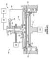
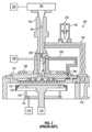
[0023]図1は、本開示のいくつかの実施態様による、ALDプロセスに適合されたガス供給システム130を含む基板処理チャンバ(処理チャンバ100)の概略図である。図2は、処理チャンバ100の断面図である。処理チャンバ100はチャンバ本体102を含み、チャンバ本体102は内部のチャンバリッドアセンブリ132の下に処理容積を有する。処理チャンバ100のスリットバルブ108は、ロボット(図示せず)が、処理チャンバ100との間で200mmまたは300mmの半導体ウエハまたはガラス基板といった基板110を送達したり取り出したりするためのアクセスを提供する。チャンバライナ177は、処理/洗浄中に使用される腐食性ガスからチャンバを保護するために、処理チャンバ100の壁に沿って配置されている。 [0023] FIG. 1 is a schematic diagram of a substrate processing chamber (processing chamber 100) that includes a
[0024]基板支持体112は、処理チャンバ100の基板受け面111上に基板110を支持する。基板支持体112は、基板支持体112と基板支持体上に配置された基板110とを昇降させるためのリフトモータ114に取り付けられている。リフトプレート116(図2に示す)は、リフトモータ118に接続されており、処理チャンバ100に取り付けられて、基板支持体112を通して移動可能に配置されたリフトピン120を上下させる。リフトピン120は、基板支持体112の表面の上方で基板110を上下させる。基板支持体112は、堆積プロセス中に基板110を基板支持体112に固定するための真空チャック(図示せず)、静電チャック(図示せず)、またはクランプリング(図示せず)を含みうる。 [0024]
[0025]基板支持体112の温度は、基板110の温度を制御するように調節されうる。例えば、基板支持体112は、抵抗ヒータ(図示せず)といった埋め込まれた加熱要素を使用して加熱されてもよく、または基板支持体112の上方に配置された加熱ランプ(図示せず)といった放射熱を使用して加熱されてもよい。パージリング122を基板支持体112上に配置し、基板110の周辺部分にパージガスを提供して基板110の周辺部分への堆積を防止するパージチャネル124を画定することができる。 [0025] The temperature of the
[0026]ガス供給システム130は、処理ガスおよび/またはパージガスといったガスをチャンバ100に提供するために、チャンバ本体102の上部に配置されている。真空システム(図示せず)は、処理チャンバ100から任意の所望のガスを排気し、処理チャンバ100内部に所望の圧力または圧力範囲を維持するのを助けるために、ポンピングチャネル179と連絡している。 [0026] A
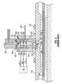
[0027]いくつかの実施態様では、チャンバリッドアセンブリ132は、チャンバリッドアセンブリ132の中央部分を通って延びるガス分散チャネル134を含む。図1および図2に示すように、ガス分散チャネル134は、基板受け面111に向かって垂直に延び、また、ガス分散チャネル134の中心軸133に沿って、リッドプレート170を通って底面160まで延びている。いくつかの実施態様では、ガス分散チャネル134の上部は、中心軸133に沿って実質的に円筒状であり、ガス分散チャネル134の下部は、中心軸133から離れる方向にテーパ付けされている。底面160は、基板支持体112の基板受け面111上に配置された基板110を実質的に覆うような大きさおよび形状である。底面160は、リッドプレート170の外側エッジからガス分散チャネル134に向かってテーパ付けされている。ガス供給システム130は、基板110を処理するために、1つまたは複数のガスをガス分散チャネル134に提供することができる。いくつかの実施態様では、ガス供給システム130は、1つのガス入口を介してガス分散チャネル134に連結されてもよい。いくつかの実施態様では、例えば図3に示すように、ガス供給システムは、複数の入口を介してガス分散チャネル134に連結されてもよい。 [0027] In some embodiments,
[0028]図3に示すように、ガス分散チャネル134を通る処理ガスの流れを示す円形ガス流174は、様々なタイプの流れパターンを含みうる。いくつかの実施態様では、分散チャネルを通過する間に、処理ガスを、ガス分散チャネル134の中心軸133の周りで回転させることができる。このような実施態様では、円形のガス流174は、渦パターン、3次元螺旋パターン、螺旋パターン、またはそれらの派生物といった様々なタイプの円形流れパターンを含むことができる。 [0028] As shown in FIG. 3,
[0029]円形のガス流174を提供することは多くの用途にとって有益であるが、本発明者らは、いくつかの用途において、円形のガス流が不均一な処理結果を招きうることを発見した。本発明者らは、ガス流が、処理されている基板110の中心付近にドーナツ状の堆積プロファイルをもたらしうることを観察した。ドーナツ状のプロファイルは、ガス分散チャネル134の漏斗形状によって引き起こされうる。したがって、いくつかの実施態様では、処理チャンバ100は、貫通する複数の開孔126を有するガス分配プレート125をさらに含む。ガス分配プレート125は、ガス分散チャネル134から基板への唯一の経路がガス分配プレート125の複数の開孔126を通るように、ガス分散チャネル134の表面まで延びる。ガス分配プレート125は、有利には、ガス分配プレート125を通るガスのチョーク流を作り出し、その結果、基板110上へのより均一な堆積が得られ、したがって、ガスの回転流によって引き起こされるドーナツ状の堆積が実質的に排除される。 [0029] Although providing a
[0030]いくつかの実施態様では、ガス分配プレート125は、例えば酸化アルミニウムまたは窒化アルミニウムといった、非腐食性セラミック材料で形成される。いくつかの実施態様では、複数の開孔126の各々は、同等の流体コンダクタンスを有しうる。いくつかの実施態様では、複数の開孔126の密度(例えば、単位面積あたりの開孔の数または開孔の開口部のサイズ)は、基板110上に所望の堆積プロファイルを達成するために、ガス分配プレート125全体で変化してもよい。例えば、より高密度の開孔126をガス分配プレート125の中心に配置し、基板のエッジに対して基板の中心での堆積速度を上昇させることで、堆積の均一性をさらに改善することができる。 [0030] In some embodiments,
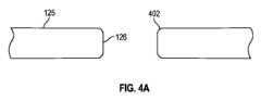
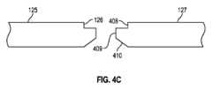
[0031]複数の開孔126は、円筒状の貫通孔として示されているが、異なるプロファイルを有してもよい。図4A~Cは、複数の開孔126のプロファイルの異なる非限定的実施態様を示す。図4Aに示される実施態様では、開孔126は、開孔を囲む湾曲したエッジ402を有する円筒状の貫通孔である。図4Bに示される実施態様では、開孔126は、開孔の中心に向かって内側にテーパ付けされている上部404と、ガス分配プレート125の上面127に対して垂直に延びる円筒状の中心部405と、開孔の中心から外側に向かってテーパ付けされている下部406とを有する貫通孔である。図4Cに示す実施態様では、開孔126は、皿穴を有する上部408と、ガス分配プレート125の上面127に対して垂直に延びる円筒状の中心部409と、開孔の中心から外側に向かってテーパ付けされている下部410とを有する貫通孔である。代替的に、複数の開孔126の他のプロファイルを使用して、基板110の処理中に最適な堆積均一性を達成してもよい。 [0031] Although the plurality of
[0032]理論によって束縛されることを望まないが、本発明者らは、ガス分散チャネル134の直径が、ガス分散チャネル134の上部から中心軸133に沿った第1の点まで一定であり、ガス分散チャネル134の第1の点から下部135まで増加することにより、ガス分散チャネル134を通るガスの断熱膨張を小さくすることができ、これが円形ガス流174に含まれる処理ガスの温度を制御するために役立ちうると考える。例えば、ガス分散チャネル134内に送達されるガスの急激な断熱膨張は、ガスの温度の低下をもたらし、ガスの凝縮および液滴の形成を引き起こしうる。一方、テーパ付けされているガス分散チャネル134は、より小さなガスの断熱膨張を提供すると考えられる。したがって、より多くの熱をガスに、またはガスから伝達することができ、このようにすることで、チャンバリッドアセンブリ132の温度を制御することによって、ガスの温度をより容易に制御することができる。ガス分散チャネル134にはテーパ付けすることができ、ガス分散チャネル134は、テーパ付けされた平面、凹面、凸面、またはそれらの組合せといった1つまたは複数のテーパ付けされた内面を含むことができるか、あるいは1つまたは複数のテーパ付けされた内面のセクション(すなわち、テーパ付けされた部分およびテーパ付けされていない部分)を含むことができる。 [0032] While not wishing to be bound by theory, the inventors believe that the diameter of
[0033]図3に示すように、ガス分散チャネル134の上部は、ハウジング375の内部領域に配置されたインサート300によって画定される。インサート300は、インサート300の上部のキャップ302と、ガス分散チャネル134を少なくとも部分的に画定する中央通路とを含む。キャップ302は、ハウジング375の上に延びて、インサート300を所定の位置に保持する。インサート300およびキャップ302は、インサート300とハウジング375との間に配置された複数のOリング385を含み、適切なシールを確実にする。インサート300は、複数の円周方向開孔を含み、これら円周方向開孔は、インサート300がハウジング375に挿入されると、対応する複数の円周方向チャネル360、365、370を形成する。複数の円周チャネル360、365、370は、対応する複数の孔340、345、350を介してガス分散チャネル134に流体連結される。図3に示される実施態様では、ガス供給システム130は、複数のガス供給ライン310、315、320を介してガス分散チャネル134に連結されている。ガス供給ライン310、315、320は、複数の円周方向チャネル360、365、370に流体連結されて、1つまたは複数のガスをガス分散チャネル134に提供する。 [0033] As shown in FIG. 3, the upper portion of
[0034]図1および図2に戻ると、処理チャンバ100は、遠隔プラズマ源(RPS)190と、一端がRPS190に、反対端がキャップ302に連結された分離カラー192と、リッドプレート170の上面に連結されたヒータプレート198と、RPS190に流体連結された洗浄ガス(すなわち、パージガス)源197とを含むチャンバ洗浄システムをさらに含む。洗浄ガス源は、処理チャンバ100を洗浄するためのプラズマを形成するのに適した任意のガスを含むことができる。いくつかの実施態様では、例えば、洗浄ガスは三フッ化窒素(NF3)であってもよい。分離カラー192は、キャップ302の中央部分に配置された複数の孔285を通してガス分散チャネル134に流体連結された内側チャネル193を含み、プラズマをRPS190からガス分散チャネル134を通して反応ゾーン164内に流す。ヒータプレート198は、ステンレス鋼で形成され、プレート全体に分散した複数の抵抗加熱要素を含むことができる。[0034] Returning to FIGS. 1 and 2, the
[0035]典型的には、ガス分散チャネル134および反応ゾーン164から第1のガスを迅速にパージするために、第1のガスがガス供給システム130によってガス分散チャネル134に供給された後、洗浄ガスがガス分散チャネル134および反応ゾーン164を通して流される。続いて、第2のガスがガス供給システム130によってガス分散チャネル134に提供され、洗浄ガスが再びガス分散チャネル134を通して反応ゾーン164に流され、ガス分散チャネル134および反応ゾーン164から第2のガスを迅速にパージする。しかしながら、ガス分配プレート125の追加は、ポンピングチャネル179への洗浄ガスの流れをチョークさせ、洗浄プロセスを延長させる。そのため、本発明者らは、第1の端部186が分離カラー192に、第2の端部188がポンピングチャネル179にそれぞれ連結された排気導管184を有する排気システム180を組み込んだ。排気導管184を内部チャネル193に選択的に流体連結させるために、排気導管184にはバルブ182が配置される。いくつかの実施態様では、例えば、バルブ182は、排気導管184を内部チャネル193に流体連結する第1の位置(図2に示される)と、排気導管184を内部チャネル193からシールする第2の位置との間で移動可能なプランジャ202を有するプランジャ型バルブであってもよい。洗浄ガスがガス分散チャネル134および反応ゾーン164を通って流れるたびに、バルブ182が開き、洗浄ガスがポンピングチャネル179に迅速に排出される。 [0035] Typically, after the first gas is supplied to the
[0036]処理チャンバ100内部の圧力がRPS190内部の圧力を超えると、処理ガスがRPS190まで流れ、RPS190に損傷を与える可能性がある。複数の孔285は、処理ガスの逆流が内側チャネル193を通ってRPS190内へと上方へ流れるのを防止するためのチョークポイントとして機能する。分離カラー192は、使用されている洗浄ガスと反応しない任意の材料で形成することができる。いくつかの実施態様では、分離カラー192は、洗浄ガスがNF3であるときはアルミニウムで形成されてもよい。いくつかの実施態様では、分離カラー192およびインサート300は、アルミニウムで形成され、使用時に腐食性ガスによる分離カラー192およびインサート300の腐食を防止するためのコーティングでコーティングされてもよい。例えば、コーティングは、ニッケルまたは酸化アルミニウムで形成されてもよい。[0036] If the pressure inside the
図3に示されるように、RPS190は約40℃以下の温度で動作する。RPS190を処理チャンバ100内で発生した熱から有利に絶縁するために、熱的分離リング394が分離カラー192とキャップ302との間に配置されている。熱的分離リング394は、熱伝導率が低い(例えば、分離カラー192およびキャップ302の熱伝導率よりも低い)金属で形成される。加えて、分離カラー192とキャップ302との間の接触面積をさらに減少させるために、分離カラー192とキャップ302との間にOリング385を配置することもできる。熱的分離リング394とOリング385との組み合わせは、処理チャンバ100内で発生する熱がRPS190に悪影響を及ぼさないことを確実にするための熱チョークとして作用する。As shown in FIG. 3,
[0038]いくつかの実施態様では、リッドプレート170が100℃を超えて加熱されると、処理チャンバ100は、Oリング385間に捕捉された処理ガスまたは副生成物がポンピングチャンネル179に排出されることを確実にするために、差動ポンピングライン250を含んでもよい。差動ポンピングライン250は、第1の端部でリッドプレート170に連結され、第1の端部の反対側の第2の端部でハウジング375に連結される。差動ポンピングラインは、ガス分散チャネル134と、2つ以上のOリング385間の領域に形成された1つまたは複数のチャネル260とに流体連結される。ガス分散チャネル134を排気するためにバルブ182が開くと、差動ポンピングラインは、Oリング385間に捕捉されたガスを排気する。 [0038] In some embodiments, when
[0039]図3に戻ると、チャンバリッドアセンブリ132の底面160の一部分は、ガス分散チャネル134に連結された中央開口部からチャンバリッドアセンブリ132の周辺部分まで、下方および外方に向かう輪郭を有するかまたは下方および外方に角度付けされており、基板110の表面を横切る(すなわち、基板の中心から基板のエッジまでの)ガス分散チャネル134からのガス流の速度プロファイルを改善するのを助けることができる。底面160は、平面、凹面、凸面、またはそれらの組み合わせといった1つまたは複数の表面を含むことができる。一実施態様では、底面160は凸状の漏斗形状である。 [0039] Returning to FIG. 3, a portion of the
[0040]一実施例では、底面160は、基板受け面111のエッジに向かって下方および外方に傾斜しており、チャンバリッドアセンブリ132の底面160と基板110との間を移動する処理ガスの速度の変動を低減するのに役立つと共に、基板110の表面の反応ガスへの均一な露出を提供することを助ける。チャンバリッドアセンブリ132の構成要素および部品は、ステンレス鋼、アルミニウム、ニッケルめっきアルミニウム、ニッケル、それらの合金、または他の適切な材料といった材料を含みうる。一実施態様では、リッドプレート170は、アルミニウム、アルミニウム合金、鋼、ステンレス鋼、それらの合金、またはそれらの組み合わせといった金属から、製造、機械加工、鍛造、または他の方法で独立して作製されうる。 [0040] In one embodiment, the
[0041]いくつかの実施態様では、ガス分散チャネル134の内面131およびチャンバリッドアセンブリ132の底面160は、ガス分散チャネル134およびチャンバリッドアセンブリ132の底面160に沿ったガスの流れを助ける鏡面研磨面を含みうる。 [0041] In some embodiments, the inner surface 131 of the
[0042]図1~図3に示されるように、処理動作中に、基板110は、ロボット(図示せず)によってスリットバルブ108を通して処理チャンバ100に送達される。基板110は、リフトピン120とロボットとの協働により、基板支持体112上に位置決めされる。基板支持体112は、基板110を上昇させて、ガス分配プレート125の下面に密接に対向させる。第1のガス流は、第2のガス流と一緒に、または別々に(すなわち、パルス)、ガス供給システム130によって処理チャンバ100のガス分散チャネル134に注入されうる。第1のガス流は、パージガス源からのパージガスの連続流と、反応ガス源からの反応ガスのパルスとを含むことができるか、または反応ガス源からの反応ガスのパルスと、パージガス源からのパージガスのパルスとを含むことができる。第2のガス流は、パージガス源からのパージガスの連続流と、反応ガス源からの反応ガスのパルスとを含むことができるか、または反応ガス源からの反応ガスのパルスと、パージガス源からのパージガスのパルスとを含むことができる。 [0042] As shown in FIGS. 1-3, during a processing operation, a
[0043]円形ガス流174は、ガス分散チャネル134を通って、続いてガス分配プレート125の複数の開孔126を通って進む。次いで、ガスが基板110の表面上に堆積される。下方に傾斜しているチャンバリッドアセンブリ132の底面160は、ガス分配プレート125の表面を横切るガス流の速度の変動を減少させるために役立つ。余剰ガス、副生成物などは、ポンピングチャネル179に流入し、次いで処理チャンバ100から排気される。処理動作を通して、ヒータプレート198は、チャンバリッドアセンブリ132を所定の温度に加熱して、処理チャンバ100(またはチャンバ内に配置された処理キット)の壁に蓄積した固体副生成物を加熱することができる。結果として、蓄積された固体副生成物が気化する。気化した副生成物は、真空システム(図示せず)およびポンピングチャネル179によって排気される。いくつかの実施態様では、所定の気温は150℃以上である。 [0043]
[0044]いくつかのプロセス条件は、例えば、気相反応を可能にするガス供給システム内の残留前駆体に起因して、ステップカバレッジ問題を引き起こしうる。典型的なALDプロセスでは、通常気相反応は回避される。したがって、本開示のいくつかの実施態様は、処理チャンバリッドおよび処理チャンバにチャンバリッドへの裏側ポンピング能力を提供する。いくつかの実施態様の装置は、プラズマ源が接続されていないサーマルチャンバリッドである。いくつかの実施態様では、チャンバリッドは、リモートプラズマを処理チャンバに提供する遠隔プラズマ源を有するように構成される。 [0044] Some process conditions can cause step coverage problems, for example, due to residual precursors in the gas supply system that enables gas phase reactions. In typical ALD processes, gas phase reactions are usually avoided. Accordingly, some embodiments of the present disclosure provide a processing chamber lid and processing chamber with backside pumping capability to the chamber lid. The apparatus of some embodiments is a thermal chamber lid with no plasma source connected. In some implementations, the chamber lid is configured with a remote plasma source that provides remote plasma to the processing chamber.
[0045]本開示の1つまたは複数の実施態様は、有利には、表面フィーチャ上の膜のステップカバレッジを改善する装置を提供する。本開示の1つまたは複数の実施態様は、有利には、残留反応ガスを除去する裏側ポンピングを追加する装置を提供する。いくつかの実施態様では、装置は、リッドプレートとシャワーヘッドとの間に捕捉された化学薬品をより効率的にポンピングするために役立つ。 [0045] One or more embodiments of the present disclosure advantageously provide an apparatus that improves step coverage of a film on a surface feature. One or more embodiments of the present disclosure advantageously provide an apparatus that adds backside pumping to remove residual reactant gases. In some embodiments, the device serves to more efficiently pump chemicals trapped between the lid plate and the showerhead.
[0046]図5は、本開示の1つまたは複数の実施態様による処理チャンバのリッドアセンブリ500を示す。ハウジング375は、ハウジング375の中心軸133に沿って延びるガス分散チャネル134を包囲する。ガス分散チャネル134は、上部134aおよび下部134bを有する。 [0046] FIG. 5 illustrates a processing
[0047]リッドプレート170は、ハウジング375に連結され、輪郭底面160を有する。輪郭底面160は、ガス分散チャネル134の下部134bに連結された中央開口部136からリッドプレート170の外周部138まで、下方および外方に延びている。図示の実施態様では、外周部138は、外周エッジ137に隣接する輪郭底面160の外側部分を指す。 [0047]
[0048]リッドアセンブリ500は、リッドプレート170の下方に配置されたガス分配プレート125を含む。ガス分配プレート125は、上面128と底面129とを有し、複数の開孔126が上面128から底面129までガス分配プレート125を貫通している。 [0048]
[0049]ガス分配プレート125は、ガス分配プレート125とリッドプレート170との間にポンピングチャネル530を形成するように構成された上部外周輪郭520を有する。図5の実施態様に示されるポンピングチャネル530は、リッドプレート170の外周底面532とガス分配プレート125の上部外周輪郭520との間に画定されている。いくつかの実施態様では、リッドプレート170の外周底面532は、輪郭底面160の外周部138よりも中心軸133から遠い。別の言い方をすれば、いくつかの実施態様では、外周底面532は、輪郭底面160を囲んでいる。 [0049]
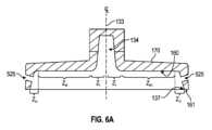
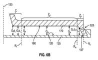
[0050]リッドプレート170の輪郭底面160とガス分配プレート125の上面128とは、間隙Gを画定する。底面160は輪郭形成されるため、間隙Gは、中心軸133からの距離の関数として可変である。いくつかの実施態様では、内側ゾーンZIは、中間ゾーンZMよりも大きな間隙を有し、中間ゾーンZMは、外側ゾーンZOよりも大きな間隙を有する。図6Aは、図5に示されるものと同様の輪郭底面160を有するリッドプレート170の概略断面図を示す。図6Bは、図5のリッドプレート170およびガス分配プレート125の概略断面図であり、中心軸133からの半径方向距離に対する空隙Gの関係を示している。図6Aでは、リッドプレート170の輪郭底面160は、内側ゾーンZI、中間ゾーンZM、および外側ゾーンZOの3つのゾーンに分離されている。この実施態様では、中間ゾーンZMにおいて、輪郭底面160は、間隙GMが均一になるように平坦である。図6Bの部分断面図では、中間ゾーンZMの間隙GMは、中間ゾーンZMの左エッジから右エッジまで均一である。内側ゾーンZIにおいて、間隙GIは、中心軸133から測定される距離xの関数である。図6Bには、内側ゾーンZIにおける間隙GIdxの2つの測定値が示されている。外側ゾーンZOでは、間隙GOは、中心軸133から測定される距離xの関数である。図6Bには、外側ゾーンZOの間隙GOdxの1つの測定値が示されている。当業者であれば、図示の測定値が説明のみを目的としていることが分かるであろう。図6Bでは、ガス分配プレート125の開孔126が説明上省略されている。[0050] The contoured
[0051]再び図6Bを参照すると、いくつかの実施態様では、内側ゾーンZIは、リッドプレート170の中心軸133から、中心軸133から内側ゾーン半径方向距離RIまで画定されている。中間ゾーンZMは、内側ゾーン半径方向距離RIから、中心軸133から中間ゾーン半径方向距離RMまで画定されている。外側ゾーンZOは、中間ゾーン半径方向距離ZMから、輪郭底面160の外周エッジ137にある外側ゾーン半径方向距離ROまで画定される。[0051] Referring again to FIG. 6B, in some embodiments, the inner zone ZI is defined from the
[0052]中間ゾーンZMのサイズは、中心軸133から外周エッジ137までの全半径方向距離に対して測定される任意の適切なサイズとすることができる。いくつかの実施態様では、中心軸133から外周エッジ137までの距離は、約50mm、100mm、150mm、または200mm以上である。いくつかの実施態様では、中心軸133から外周エッジ137までの距離は、処理される基板の半径よりも大きい。例えば、300mmの基板が処理されている実施態様では、中心軸から基板のエッジまでの半径方向距離は、基板が中心であると仮定すると、150mmである。この実施例では、中心軸133から外周エッジ137までの距離は150mm以上である。[0052] The size of the intermediate zone ZM may be any suitable size measured relative to the total radial distance from the
[0053]いくつかの実施態様では、中心軸133から中間ゾーン半径方向距離ZMまでの距離は、約50mm、100mm、150mm、または200mm以上である。いくつかの実施態様では、中心軸133から中間ゾーン半径方向距離ZMまでの距離は、処理される基板の半径よりも大きい。例えば、300mmの基板が処理されている実施態様では、中心軸から基板のエッジまでの半径方向距離は、基板が中心であると仮定すると、150mmである。この実施例では、中心軸133から中間ゾーン半径方向距離ZMまでの距離は、例えば150mm以上である。[0053] In some implementations, the distance from
[0054]いくつかの実施態様では、リッドプレート170の中間ゾーンZMのサイズは、中心軸から外側ゾーン半径方向距離ROまでの距離の約10%から約90%の範囲である。いくつかの実施態様では、リッドプレート170の中間ゾーンZMのサイズは、中心軸133から外側ゾーン半径方向距離ROまでの距離の約20%から約80%の範囲、または約30%から約70%の範囲、または約40%から約60%の範囲である。[0054] In some embodiments, the size of the middle zone ZM of the
[0055]いくつかの実施態様では、中間ゾーンZMにおける実質的に均一な間隙は、約0.1インチから約2インチ(約2.5mmから約51mm)の範囲である。このように使用される場合、「実質的に均一な間隙」という用語は、中間ゾーンZM内の任意の半径方向距離にある間隙が、中間ゾーンZMにおける平均間隙の5%、2%、1%または0.5%以内であることを意味する。[0055] In some embodiments, the substantially uniform gap in the intermediate zone ZM ranges from about 0.1 inch to about 2 inches (about 2.5 mm to about 51 mm). When used in this manner, the term "substantially uniform gap" means that the gap at any radial distance within the intermediate zoneZM is 5%, 2%, 2%, It means within 1% or 0.5%.
[0056]いくつかの実施態様では、外側ゾーンZOは、中間ゾーンZMからリッドプレート170の前面161まで傾斜している。いくつかの実施態様では、外側ゾーンZOは、中間ゾーンZMからガス分配プレート125の上面128まで傾斜している。平坦な中間ゾーンZMに対する外側ゾーンZOの傾斜は、図7に示すように外側ゾーン角θを形成する。いくつかの実施態様では、外側ゾーン角は、約15°から約75°の範囲、または約30°から約60°の範囲、または約40°から約50°の範囲である。[0056] In some embodiments, the outer zone ZO is sloped from the middle zone ZM to the
[0057]図5および図7に示されるように、いくつかの実施態様では、輪郭底面160の外側ゾーンZOは、リッドプレート170に形成されたポンピング孔525を通してポンピングチャネル530に接続される。いくつかの実施態様では、ポンピング孔525は、輪郭底面160の外側ゾーンZOに形成される。ポンピング孔525の数は、例えば、リッドプレート170のサイズに基づいて変化させることができる。いくつかの実施態様では、約24から約144個のポンピング孔525が存在する。[0057] As shown in FIGS. 5 and 7, in some embodiments, the outer zone ZO of the contoured
[0058]図7に示すように、ポンピング孔は、輪郭底面160の外側ゾーンZOと角度φで交差する。いくつかの実施態様では、角度φは、約75°から約105°の範囲、または約80°から約100°の範囲、または約85°から約95°の範囲、または約88°から約92°の範囲である。[0058] As shown in FIG. 7, the pumping holes intersect the outer zone ZO of the contoured
[0059]いくつかの実施態様のリッドアセンブリ500は、図5に示されるように、ポンピングチャネル530と流体連結する少なくとも1つのポンプポート560を含む。ポンプポート560は、リッドプレート170に接続された別個の構成要素とすることができる。いくつかの実施態様では、異なる半径方向位置でポンピングチャネル530に接続された2つ以上のポンプポート560が存在する。いくつかの実施態様では、ポンプポートの各々は、排気目的のために別個の真空源に接続される。いくつかの実施態様では、ポンプポートは、単一の真空源と流体連結している。いくつかの実施態様では、ポンプポートは、ポンピングチャネル179と流体連結している(図1参照)。 [0059] The
[0060]図8は、本開示の1つまたは複数の実施態様によるリッドアセンブリ600を示している。リッドプレート170の輪郭底面160は、輪郭底面160の内側エッジ610から外周エッジ137まで傾斜している。 [0060] FIG. 8 illustrates a
[0061]輪郭底面160の傾斜は、外周エッジ137で最小となるまで減少する間隙Gを作り出す。いくつかの実施態様では、最小間隙Gは、約0.01インチから約1インチ(約0.25mmから約25.4mm)の範囲、または約0.05インチから約0.5インチ(約1.25mmから約12.7mm)の範囲である。 [0061] The slope of the
[0062]本開示のさらなる実施態様は、リッドアセンブリ500またはリッドアセンブリ600を組み込んだ処理チャンバを対象とする。 [0062] Further embodiments of the present disclosure are directed to processing chambers that incorporate a
[0063]上述の明細書では、本開示の実施態様が、その具体的な例示的実施態様を参照して説明された。特許請求の範囲に記載されている本開示の実施態様のより広い主旨および範囲から逸脱することなく、様々な修正を行うことができることが明らかだろう。したがって、本明細書および図面は、限定ではなく例示を意味すると見なされるべきである。 [0063] In the foregoing specification, embodiments of the present disclosure are described with reference to specific exemplary implementations thereof. It will be apparent that various modifications may be made without departing from the broader spirit and scope of the embodiments of the disclosure as set forth in the claims. Accordingly, the specification and drawings are to be regarded in an illustrative rather than a restrictive sense.
Claims (11)
Translated fromJapanese前記ハウジングに連結されたリッドプレートであって、前記ガス分散チャネルの前記下部に連結された中央開口部から前記リッドプレートの周辺部分まで下方および外方に延びる輪郭底面を有する前記リッドプレート;および
前記リッドプレートの下方に配置されたガス分配プレートであって、前記ガス分配プレートと前記リッドプレートとの間にポンピングチャネルを形成するように構成された上部外周輪郭を有し、かつ、上面と、底面であって、前記上面から前記底面まで前記ガス分配プレートを貫通する複数の開孔を有する前記底面とを有しており、前記リッドプレートの前記輪郭底面と前記ガス分配プレートの上面とが間隙を画定している、前記ガス分配プレート
を備え、
前記リッドプレートの前記輪郭底面が、内側ゾーン、中間ゾーンおよび外側ゾーンを含み、
前記内側ゾーンが、前記リッドプレートの中心軸から、前記中心軸から内側ゾーン半径方向距離まで画定されており、前記中間ゾーンが、前記内側ゾーン半径方向距離から、前記中心軸から中間ゾーン半径方向距離まで画定されており、前記外側ゾーンが、前記中間ゾーン半径方向距離から、前記輪郭底面の外周エッジにおける外側ゾーン半径方向距離まで画定され、
前記リッドプレートの前記輪郭底面の前記内側ゾーンが、前記リッドプレートの前記輪郭底面の前記中間ゾーンよりも大きな間隙を有し、前記リッドプレートの前記輪郭底面の前記中間ゾーンが、前記リッドプレートの前記輪郭底面の前記外側ゾーンよりも大きな間隙を有し、
前記リッドプレートの前記輪郭底面の前記中間ゾーンが、実質的に均一な間隙を形成している、
処理チャンバのリッドアセンブリ。a housing surrounding a gas distribution channel extending along a central axis, the gas distribution channel having an upper portion and a lower portion;
a lid plate connected to the housing, the lid plate having a contoured bottom surface extending downwardly and outwardly from a central opening connected to the lower portion of the gas distributionchannel to a peripheral portion of the lid plate; and a gas distribution plate disposed below the lid plate, the gas distribution plate having an upper circumferential contour configured to form a pumping channel between the gas distribution plate and the lid plate; and a bottom surface having a plurality of apertures passing through the gas distribution plate from the top surface to the bottom surface, the contoured bottom surface of the lid plate and the top surface of the gas distribution plate defining a gap;
the contoured bottom surface of the lid plate includes an inner zone, a middle zone and an outer zone;
the inner zone is defined from a central axis of the lid plate to an inner zone radial distance from the central axis; and the intermediate zone is defined from the inner zone radial distance to an intermediate zone radial distance from the central axis. and the outer zone isdefined from the intermediate zone radial distance to an outer zone radial distance at an outer peripheral edge of the contour base;
the inner zone of the contoured bottom surface of the lid plate has a larger gap than the intermediate zone of the contoured bottom surface of the lid plate; having a gap larger than the outer zone of the contour bottom surface;
the intermediate zone of the contoured bottom surface of the lid plate defines a substantially uniform gap;
Processing chamber lid assembly.
Priority Applications (1)
| Application Number | Priority Date | Filing Date | Title |
|---|---|---|---|
| JP2023206653AJP7702468B2 (en) | 2019-05-28 | 2023-12-07 | Lid for thermal processing chamber with backside pumping - Patents.com |
Applications Claiming Priority (3)
| Application Number | Priority Date | Filing Date | Title |
|---|---|---|---|
| US201962853699P | 2019-05-28 | 2019-05-28 | |
| US62/853,699 | 2019-05-28 | ||
| PCT/US2020/034903WO2020243288A1 (en) | 2019-05-28 | 2020-05-28 | Thermal process chamber lid with backside pumping |
Related Child Applications (1)
| Application Number | Title | Priority Date | Filing Date |
|---|---|---|---|
| JP2023206653ADivisionJP7702468B2 (en) | 2019-05-28 | 2023-12-07 | Lid for thermal processing chamber with backside pumping - Patents.com |
Publications (2)
| Publication Number | Publication Date |
|---|---|
| JP2022534893A JP2022534893A (en) | 2022-08-04 |
| JP7401560B2true JP7401560B2 (en) | 2023-12-19 |
Family
ID=73549739
Family Applications (2)
| Application Number | Title | Priority Date | Filing Date |
|---|---|---|---|
| JP2021569867AActiveJP7401560B2 (en) | 2019-05-28 | 2020-05-28 | Heat treatment chamber lid with backside pumping |
| JP2023206653AActiveJP7702468B2 (en) | 2019-05-28 | 2023-12-07 | Lid for thermal processing chamber with backside pumping - Patents.com |
Family Applications After (1)
| Application Number | Title | Priority Date | Filing Date |
|---|---|---|---|
| JP2023206653AActiveJP7702468B2 (en) | 2019-05-28 | 2023-12-07 | Lid for thermal processing chamber with backside pumping - Patents.com |
Country Status (5)
| Country | Link |
|---|---|
| US (3) | US11335591B2 (en) |
| JP (2) | JP7401560B2 (en) |
| KR (2) | KR102742593B1 (en) |
| TW (3) | TWI838240B (en) |
| WO (1) | WO2020243288A1 (en) |
Families Citing this family (8)
| Publication number | Priority date | Publication date | Assignee | Title |
|---|---|---|---|---|
| US9793096B2 (en)* | 2014-09-12 | 2017-10-17 | Lam Research Corporation | Systems and methods for suppressing parasitic plasma and reducing within-wafer non-uniformity |
| US11384432B2 (en)* | 2015-04-22 | 2022-07-12 | Applied Materials, Inc. | Atomic layer deposition chamber with funnel-shaped gas dispersion channel and gas distribution plate |
| TWI838240B (en)* | 2019-05-28 | 2024-04-01 | 美商應用材料股份有限公司 | Thermal process chamber lid with backside pumping |
| CN119980191A (en)* | 2019-08-28 | 2025-05-13 | 朗姆研究公司 | Metal Deposition |
| WO2021257462A1 (en)* | 2020-06-15 | 2021-12-23 | Lam Research Corporation | Showerhead faceplates with angled gas distribution passages for semiconductor processing tools |
| US11584993B2 (en) | 2020-10-19 | 2023-02-21 | Applied Materials, Inc. | Thermally uniform deposition station |
| US11742185B2 (en)* | 2021-03-26 | 2023-08-29 | Applied Materials, Inc. | Uniform in situ cleaning and deposition |
| US20250191897A1 (en)* | 2023-12-07 | 2025-06-12 | Applied Materials, Inc. | Cross flow gas delivery for particle reduction |
Citations (5)
| Publication number | Priority date | Publication date | Assignee | Title |
|---|---|---|---|---|
| JP2010212335A (en) | 2009-03-09 | 2010-09-24 | Hitachi Kokusai Electric Inc | Substrate-treating device |
| JP2016204729A (en) | 2015-04-28 | 2016-12-08 | 株式会社日立国際電気 | Substrate processing apparatus, semiconductor device manufacturing method, and program |
| JP2017123425A (en) | 2016-01-08 | 2017-07-13 | 株式会社日立国際電気 | Substrate processing apparatus, semiconductor device manufacturing method, program and recording medium |
| JP2017183393A (en) | 2016-03-29 | 2017-10-05 | 株式会社日立国際電気 | Substrate processing apparatus, manufacturing method of semiconductor device, and program |
| JP2018138691A (en) | 2016-12-15 | 2018-09-06 | エーエスエム アイピー ホールディング ビー.ブイ. | Shower plate structure for film formation suppression gas exhaust |
Family Cites Families (21)
| Publication number | Priority date | Publication date | Assignee | Title |
|---|---|---|---|---|
| US6106625A (en)* | 1997-12-02 | 2000-08-22 | Applied Materials, Inc. | Reactor useful for chemical vapor deposition of titanium nitride |
| JP3479833B2 (en)* | 2000-08-22 | 2003-12-15 | 日本電気株式会社 | Laser correction method and apparatus |
| TWI224815B (en)* | 2001-08-01 | 2004-12-01 | Tokyo Electron Ltd | Gas processing apparatus and gas processing method |
| WO2005015613A2 (en) | 2003-08-07 | 2005-02-17 | Sundew Technologies, Llc | Perimeter partition-valve with protected seals |
| US7408225B2 (en)* | 2003-10-09 | 2008-08-05 | Asm Japan K.K. | Apparatus and method for forming thin film using upstream and downstream exhaust mechanisms |
| CN101370963B (en)* | 2006-01-19 | 2012-03-28 | Asm美国公司 | High temperature atomic layer deposition intake manifold |
| JP4527670B2 (en)* | 2006-01-25 | 2010-08-18 | 東京エレクトロン株式会社 | Heat treatment apparatus, heat treatment method, control program, and computer-readable storage medium |
| US7740705B2 (en)* | 2006-03-08 | 2010-06-22 | Tokyo Electron Limited | Exhaust apparatus configured to reduce particle contamination in a deposition system |
| SG183536A1 (en) | 2010-03-12 | 2012-09-27 | Applied Materials Inc | Atomic layer deposition chamber with multi inject |
| US9982340B2 (en) | 2012-04-04 | 2018-05-29 | Taiwan Semiconductor Manufacturing Co. Ltd. | Shower head apparatus and method for controlling plasma or gas distribution |
| US10714315B2 (en)* | 2012-10-12 | 2020-07-14 | Asm Ip Holdings B.V. | Semiconductor reaction chamber showerhead |
| US10781516B2 (en)* | 2013-06-28 | 2020-09-22 | Lam Research Corporation | Chemical deposition chamber having gas seal |
| JP5807084B2 (en)* | 2013-09-30 | 2015-11-10 | 株式会社日立国際電気 | Semiconductor device manufacturing method, substrate processing apparatus, and program |
| TWI524388B (en)* | 2013-12-27 | 2016-03-01 | Hitachi Int Electric Inc | A substrate processing apparatus, a manufacturing method of a semiconductor device, and a recording medium |
| JP5800969B1 (en)* | 2014-08-27 | 2015-10-28 | 株式会社日立国際電気 | Substrate processing apparatus, semiconductor device manufacturing method, program, and recording medium |
| US10407771B2 (en) | 2014-10-06 | 2019-09-10 | Applied Materials, Inc. | Atomic layer deposition chamber with thermal lid |
| US11384432B2 (en)* | 2015-04-22 | 2022-07-12 | Applied Materials, Inc. | Atomic layer deposition chamber with funnel-shaped gas dispersion channel and gas distribution plate |
| KR102417934B1 (en)* | 2015-07-07 | 2022-07-07 | 에이에스엠 아이피 홀딩 비.브이. | Thin Film Deposition Apparatus |
| JP6198086B1 (en) | 2016-03-29 | 2017-09-20 | Necプラットフォームズ株式会社 | Board guide member and housing |
| KR102546317B1 (en) | 2016-11-15 | 2023-06-21 | 에이에스엠 아이피 홀딩 비.브이. | Gas supply unit and substrate processing apparatus including the same |
| TWI838240B (en)* | 2019-05-28 | 2024-04-01 | 美商應用材料股份有限公司 | Thermal process chamber lid with backside pumping |
- 2020
- 2020-05-28TWTW112116780Apatent/TWI838240B/enactive
- 2020-05-28TWTW109117824Apatent/TWI803753B/enactive
- 2020-05-28JPJP2021569867Apatent/JP7401560B2/enactiveActive
- 2020-05-28WOPCT/US2020/034903patent/WO2020243288A1/ennot_activeCeased
- 2020-05-28USUS16/886,116patent/US11335591B2/enactiveActive
- 2020-05-28TWTW113108101Apatent/TWI871205B/enactive
- 2020-05-28KRKR1020217042885Apatent/KR102742593B1/enactiveActive
- 2020-05-28KRKR1020247040898Apatent/KR20250004380A/enactivePending
- 2022
- 2022-04-14USUS17/720,836patent/US11715667B2/enactiveActive
- 2023
- 2023-06-12USUS18/208,409patent/US12387975B2/enactiveActive
- 2023-12-07JPJP2023206653Apatent/JP7702468B2/enactiveActive
Patent Citations (5)
| Publication number | Priority date | Publication date | Assignee | Title |
|---|---|---|---|---|
| JP2010212335A (en) | 2009-03-09 | 2010-09-24 | Hitachi Kokusai Electric Inc | Substrate-treating device |
| JP2016204729A (en) | 2015-04-28 | 2016-12-08 | 株式会社日立国際電気 | Substrate processing apparatus, semiconductor device manufacturing method, and program |
| JP2017123425A (en) | 2016-01-08 | 2017-07-13 | 株式会社日立国際電気 | Substrate processing apparatus, semiconductor device manufacturing method, program and recording medium |
| JP2017183393A (en) | 2016-03-29 | 2017-10-05 | 株式会社日立国際電気 | Substrate processing apparatus, manufacturing method of semiconductor device, and program |
| JP2018138691A (en) | 2016-12-15 | 2018-09-06 | エーエスエム アイピー ホールディング ビー.ブイ. | Shower plate structure for film formation suppression gas exhaust |
Also Published As
| Publication number | Publication date |
|---|---|
| WO2020243288A1 (en) | 2020-12-03 |
| TW202120738A (en) | 2021-06-01 |
| JP2022534893A (en) | 2022-08-04 |
| TWI871205B (en) | 2025-01-21 |
| TW202336270A (en) | 2023-09-16 |
| TWI838240B (en) | 2024-04-01 |
| US20220246471A1 (en) | 2022-08-04 |
| KR102742593B1 (en) | 2024-12-16 |
| JP2024037816A (en) | 2024-03-19 |
| US12387975B2 (en) | 2025-08-12 |
| US11335591B2 (en) | 2022-05-17 |
| TW202428929A (en) | 2024-07-16 |
| KR20220002741A (en) | 2022-01-06 |
| US11715667B2 (en) | 2023-08-01 |
| US20200381295A1 (en) | 2020-12-03 |
| TWI803753B (en) | 2023-06-01 |
| JP7702468B2 (en) | 2025-07-03 |
| KR20250004380A (en) | 2025-01-07 |
| US20230335434A1 (en) | 2023-10-19 |
Similar Documents
| Publication | Publication Date | Title |
|---|---|---|
| US11932939B2 (en) | Lids and lid assembly kits for atomic layer deposition chambers | |
| JP7401560B2 (en) | Heat treatment chamber lid with backside pumping | |
| JP2023509386A (en) | Showerhead for ALD precursor delivery | |
| KR20200098739A (en) | Atomic layer deposition chamber with thermal lid | |
| US20190048467A1 (en) | Showerhead and process chamber incorporating same | |
| US20230009859A1 (en) | Asymmetric purged block beneath wafer plane to manage non-uniformity |
Legal Events
| Date | Code | Title | Description |
|---|---|---|---|
| A621 | Written request for application examination | Free format text:JAPANESE INTERMEDIATE CODE: A621 Effective date:20220121 | |
| A977 | Report on retrieval | Free format text:JAPANESE INTERMEDIATE CODE: A971007 Effective date:20221222 | |
| A131 | Notification of reasons for refusal | Free format text:JAPANESE INTERMEDIATE CODE: A131 Effective date:20230117 | |
| A521 | Request for written amendment filed | Free format text:JAPANESE INTERMEDIATE CODE: A523 Effective date:20230414 | |
| A131 | Notification of reasons for refusal | Free format text:JAPANESE INTERMEDIATE CODE: A131 Effective date:20230711 | |
| A521 | Request for written amendment filed | Free format text:JAPANESE INTERMEDIATE CODE: A523 Effective date:20231011 | |
| TRDD | Decision of grant or rejection written | ||
| A01 | Written decision to grant a patent or to grant a registration (utility model) | Free format text:JAPANESE INTERMEDIATE CODE: A01 Effective date:20231107 | |
| A61 | First payment of annual fees (during grant procedure) | Free format text:JAPANESE INTERMEDIATE CODE: A61 Effective date:20231207 | |
| R150 | Certificate of patent or registration of utility model | Ref document number:7401560 Country of ref document:JP Free format text:JAPANESE INTERMEDIATE CODE: R150 |