JP7400085B2 - Atherectomy system using electromagnetic guide wire clamp - Google Patents
Atherectomy system using electromagnetic guide wire clampDownload PDFInfo
- Publication number
- JP7400085B2 JP7400085B2JP2022516170AJP2022516170AJP7400085B2JP 7400085 B2JP7400085 B2JP 7400085B2JP 2022516170 AJP2022516170 AJP 2022516170AJP 2022516170 AJP2022516170 AJP 2022516170AJP 7400085 B2JP7400085 B2JP 7400085B2
- Authority
- JP
- Japan
- Prior art keywords
- guidewire
- electromagnet
- clamp
- atherectomy
- steel plunger
- Prior art date
- Legal status (The legal status is an assumption and is not a legal conclusion. Google has not performed a legal analysis and makes no representation as to the accuracy of the status listed.)
- Active
Links
Images


Classifications
- A—HUMAN NECESSITIES
- A61—MEDICAL OR VETERINARY SCIENCE; HYGIENE
- A61B—DIAGNOSIS; SURGERY; IDENTIFICATION
- A61B17/00—Surgical instruments, devices or methods
- A61B17/32—Surgical cutting instruments
- A61B17/3205—Excision instruments
- A61B17/3207—Atherectomy devices working by cutting or abrading; Similar devices specially adapted for non-vascular obstructions
- A61B17/320758—Atherectomy devices working by cutting or abrading; Similar devices specially adapted for non-vascular obstructions with a rotating cutting instrument, e.g. motor driven
- A—HUMAN NECESSITIES
- A61—MEDICAL OR VETERINARY SCIENCE; HYGIENE
- A61B—DIAGNOSIS; SURGERY; IDENTIFICATION
- A61B17/00—Surgical instruments, devices or methods
- A61B2017/00017—Electrical control of surgical instruments
- A61B2017/00199—Electrical control of surgical instruments with a console, e.g. a control panel with a display
- A—HUMAN NECESSITIES
- A61—MEDICAL OR VETERINARY SCIENCE; HYGIENE
- A61B—DIAGNOSIS; SURGERY; IDENTIFICATION
- A61B17/00—Surgical instruments, devices or methods
- A61B2017/00367—Details of actuation of instruments, e.g. relations between pushing buttons, or the like, and activation of the tool, working tip, or the like
- A61B2017/00398—Details of actuation of instruments, e.g. relations between pushing buttons, or the like, and activation of the tool, working tip, or the like using powered actuators, e.g. stepper motors, solenoids
- A—HUMAN NECESSITIES
- A61—MEDICAL OR VETERINARY SCIENCE; HYGIENE
- A61B—DIAGNOSIS; SURGERY; IDENTIFICATION
- A61B17/00—Surgical instruments, devices or methods
- A61B2017/0042—Surgical instruments, devices or methods with special provisions for gripping
- A—HUMAN NECESSITIES
- A61—MEDICAL OR VETERINARY SCIENCE; HYGIENE
- A61B—DIAGNOSIS; SURGERY; IDENTIFICATION
- A61B17/00—Surgical instruments, devices or methods
- A61B2017/00831—Material properties
- A61B2017/00876—Material properties magnetic
- A—HUMAN NECESSITIES
- A61—MEDICAL OR VETERINARY SCIENCE; HYGIENE
- A61B—DIAGNOSIS; SURGERY; IDENTIFICATION
- A61B17/00—Surgical instruments, devices or methods
- A61B17/22—Implements for squeezing-off ulcers or the like on inner organs of the body; Implements for scraping-out cavities of body organs, e.g. bones; for invasive removal or destruction of calculus using mechanical vibrations; for removing obstructions in blood vessels, not otherwise provided for
- A61B2017/22038—Implements for squeezing-off ulcers or the like on inner organs of the body; Implements for scraping-out cavities of body organs, e.g. bones; for invasive removal or destruction of calculus using mechanical vibrations; for removing obstructions in blood vessels, not otherwise provided for with a guide wire
- A61B2017/22049—Means for locking the guide wire in the catheter
- A—HUMAN NECESSITIES
- A61—MEDICAL OR VETERINARY SCIENCE; HYGIENE
- A61M—DEVICES FOR INTRODUCING MEDIA INTO, OR ONTO, THE BODY; DEVICES FOR TRANSDUCING BODY MEDIA OR FOR TAKING MEDIA FROM THE BODY; DEVICES FOR PRODUCING OR ENDING SLEEP OR STUPOR
- A61M25/00—Catheters; Hollow probes
- A61M25/01—Introducing, guiding, advancing, emplacing or holding catheters
- A61M25/09—Guide wires
- A61M2025/09125—Device for locking a guide wire in a fixed position with respect to the catheter or the human body
Landscapes
- Health & Medical Sciences (AREA)
- Surgery (AREA)
- Life Sciences & Earth Sciences (AREA)
- Biomedical Technology (AREA)
- Nuclear Medicine, Radiotherapy & Molecular Imaging (AREA)
- Engineering & Computer Science (AREA)
- Vascular Medicine (AREA)
- Heart & Thoracic Surgery (AREA)
- Medical Informatics (AREA)
- Molecular Biology (AREA)
- Animal Behavior & Ethology (AREA)
- General Health & Medical Sciences (AREA)
- Public Health (AREA)
- Veterinary Medicine (AREA)
- Surgical Instruments (AREA)
Description
Translated fromJapanese本開示は医療装置、及び医療装置を製造及び使用するための方法に関する。さらに具体的には本開示は、体管腔から閉塞物を取り除くための装置及び方法に関する。さらに本開示は、血管のような体管腔の閉塞を通過する通路を形成するためのアテレクトミイ装置に関する。 TECHNICAL FIELD This disclosure relates to medical devices and methods for making and using medical devices. More specifically, the present disclosure relates to devices and methods for removing obstructions from body lumens. Further, the present disclosure relates to an atherectomy device for creating a passageway through an occlusion in a body lumen, such as a blood vessel.
多くの患者が、血流を制限する動脈及び他の血管の閉塞に苦しむ。閉塞は、血管の閉塞部を通る血流を減少させる部分閉塞、又は閉塞した血管を通る血流を実質的に遮断する完全閉塞(例えば慢性完全閉塞病変)であり得る。場合によってはステントが、治療される閉塞の領域に配置され得る。しかしながら再狭窄がステント内に起こることにより、さらに血管を塞ぐとともに血流を制限し得る。血行再建術は、閉塞を通る穴を作製するか、又は拡大するために閉塞を貫通するための様々な装置を使用することを含む。アテレクトミイは、表面上に切断要素を有するカテーテルが閉塞を通る通路を形成するか、又は拡大するために閉塞を通って進められる一つの技術である。閉塞を横断することを容易にするための代わりのアテレクトミイ装置の必要性が残されている。 Many patients suffer from blockages in arteries and other blood vessels that restrict blood flow. The occlusion can be a partial occlusion, which reduces blood flow through the occluded portion of the blood vessel, or a complete occlusion, which substantially blocks blood flow through the occluded blood vessel (eg, a chronic total occlusion lesion). A stent may optionally be placed in the area of the occlusion to be treated. However, restenosis can occur within the stent, further occluding the blood vessel and restricting blood flow. Revascularization involves the use of various devices to penetrate the occlusion to create or enlarge a hole through the occlusion. Atherectomy is one technique in which a catheter having a cutting element on its surface is advanced through an occlusion to create or enlarge a passageway through the occlusion. There remains a need for alternative atherectomy devices to facilitate crossing the occlusion.
本開示は、医療装置の設計、材料、製造方法及び代替品の使用を提供する。例えばアテレクトミイシステムは、アテレクトミイバー、及びアテレクトミイバーを回転可能に作動させるように適合された駆動機構を含む。駆動機構は、そこを通って延びるガイドワイヤを収容できるように適合される。コントローラは、駆動機構の動作を制御するように適合される。ガイドワイヤは、駆動機構を通って延びるとともに、電磁ガイドワイヤクランプは、駆動機構に対してガイドワイヤを解放可能に固定するように適合される。 The present disclosure provides medical device designs, materials, manufacturing methods, and alternative uses. For example, an atherectomy system includes an atherectomy bar and a drive mechanism adapted to rotatably actuate the atherectomy bar. The drive mechanism is adapted to accommodate a guidewire extending therethrough. The controller is adapted to control operation of the drive mechanism. A guidewire extends through the drive mechanism and an electromagnetic guidewire clamp is adapted to releasably secure the guidewire relative to the drive mechanism.
あるいは、又はさらに電磁ガイドワイヤクランプは、クランプハウジング、クランプハウジングの中に固定された電磁石、及びクランプハウジングの中に摺動自在に配置されたスチールプランジャを含み得る。そのためスチールプランジャは、電磁石が作動された時に電磁石に向かって移動できるとともに、電磁石が作動されていない時に電磁石から離間するように移動できる。電磁石を作動することにより、電磁石に向かってスチールプランジャを移動させ、それによって電磁石とスチールプランジャとの間でガイドワイヤを締め付ける。 Alternatively, or in addition, the electromagnetic guidewire clamp may include a clamp housing, an electromagnet secured within the clamp housing, and a steel plunger slidably disposed within the clamp housing. The steel plunger can thus move towards the electromagnet when the electromagnet is activated and away from the electromagnet when the electromagnet is not activated. Activating the electromagnet moves the steel plunger toward the electromagnet, thereby tightening the guide wire between the electromagnet and the steel plunger.
あるいは、又はさらに電磁ガイドワイヤクランプは、電磁ガイドワイヤクランプを通してガイドワイヤを進めることを容易にするために、クランプハウジングの中に成形されたガイドワイヤ導入部をさらに含み得る。 Alternatively, or in addition, the electromagnetic guidewire clamp may further include a guidewire introducer molded into the clamp housing to facilitate advancing the guidewire through the electromagnetic guidewire clamp.
あるいは、又はさらに電磁ガイドワイヤクランプは、スチールプランジャに対向する電磁石の側面に固定された第一の弾性パッド、及び電磁石に対向するスチールプランジャの側面に固定された第二の弾性パッドをさらに含み得る。 Alternatively, or in addition, the electromagnetic guide wire clamp may further include a first resilient pad secured to the side of the electromagnet opposite the steel plunger, and a second resilient pad secured to the side of the steel plunger opposite the electromagnet. .
あるいは、又はさらにクランプハウジングは、スチールプランジャを収容するように適合された下部クランプハウジング、及び電磁石を収容するように適合された上部クランプハウジングを含み得る。 Alternatively, or in addition, the clamp housing may include a lower clamp housing adapted to house the steel plunger and an upper clamp housing adapted to house the electromagnet.
あるいは、又はさらにクランプハウジングは、上部クランプハウジングに対して固定されたキャップをさらに含み得る。
あるいは、又はさらに電磁石は、キャップを通って電磁石の中に延びる取り付け具によって上部クランプハウジングに対して固定され得る。Alternatively or additionally, the clamp housing may further include a cap secured to the upper clamp housing.
Alternatively, or additionally, the electromagnet may be secured to the upper clamp housing by a fitting that extends through the cap and into the electromagnet.
あるいは、又はさらに駆動機構は、アテレクトミイバーと連結された駆動ケーブル、及び駆動ケーブルを回転させるように適合された駆動モータを含み得る。
あるいは、又はさらにアテレクトミイシステムは、ハンドルハウジングを有するハンドルをさらに含み、駆動モータはハンドルハウジング内に配置され得る。Alternatively, or in addition, the drive mechanism may include a drive cable coupled to the atherectomy bar and a drive motor adapted to rotate the drive cable.
Alternatively, or in addition, the atherectomy system may further include a handle having a handle housing, and the drive motor may be disposed within the handle housing.
あるいは、又はさらに電磁ガイドワイヤクランプは、ハンドルハウジング内に配置され得る。
別の例は、ハンドルハウジングを含むハンドル及びアテレクトミイバーを含む、アテレクトミイシステムである。駆動モータは、ハンドルハウジング内に配置されるとともに、駆動モータからアテレクトミイバーまで延びる駆動ケーブルによってアテレクトミイバーを回転可能に作動させるように適合される。駆動ケーブルは、その駆動ケーブルを通って延びるガイドワイヤを収容するように適合される。コントローラは、駆動機構の動作を制御するように適合される。電磁ガイドワイヤクランプは、駆動ケーブルに対してガイドワイヤを解放可能に固定するように適合されるとともに、電磁石、及び電磁石に対して摺動自在に配置されたスチールプランジャを含む。そのためスチールプランジャは、電磁石が作動された時に電磁石に向かって移動できるとともに電磁石とスチールプランジャとの間にガイドワイヤを締め付ける。Alternatively, or in addition, an electromagnetic guidewire clamp may be disposed within the handle housing.
Another example is an atherectomy system that includes a handle that includes a handle housing and an atherectomy bar. A drive motor is disposed within the handle housing and is adapted to rotatably actuate the atherosclerosis bar with a drive cable extending from the drive motor to the atherectomy bar. The drive cable is adapted to accommodate a guidewire extending therethrough. The controller is adapted to control operation of the drive mechanism. The electromagnetic guidewire clamp is adapted to releasably secure the guidewire to the drive cable and includes an electromagnet and a steel plunger slidably disposed relative to the electromagnet. The steel plunger is therefore able to move towards the electromagnet when the electromagnet is actuated and clamps the guide wire between the electromagnet and the steel plunger.
あるいは、又はさらに電磁石は、ハンドルハウジングに対して固定され得る。
あるいは、又はさらにスチールプランジャは、ハンドルハウジングに対して摺動自在に固定され得る。Alternatively, or in addition, the electromagnet may be fixed to the handle housing.
Alternatively, or in addition, the steel plunger may be slidably secured to the handle housing.
あるいは、又はさらにアテレクトミイシステムは、ハンドルハウジング内に固定された電磁ガイドワイヤクランプハウジングをさらに含み得る。
あるいは、又はさらに電磁ガイドワイヤクランプハウジングは、スチールプランジャを収容するように適合され得る下部クランプハウジング、及び電磁石を収容するように適合され得る上部クランプハウジングを含み得る。Alternatively, or in addition, the atherectomy system may further include an electromagnetic guide wire clamp housing secured within the handle housing.
Alternatively, or in addition, the electromagnetic guidewire clamp housing may include a lower clamp housing that may be adapted to house a steel plunger and an upper clamp housing that may be adapted to house an electromagnet.
あるいは、又はさらに電磁ガイドワイヤクランプハウジングは、上部クランプハウジングに対して固定されたキャップをさらに含み得る。
あるいは、又はさらに電磁石は、キャップを通って電磁石の中に延びる取り付け具によって上部クランプハウジングに対して固定され得る。Alternatively or additionally, the electromagnetic guidewire clamp housing may further include a cap secured to the upper clamp housing.
Alternatively, or additionally, the electromagnet may be secured to the upper clamp housing by a fitting that extends through the cap and into the electromagnet.
あるいは、又はさらに電磁ガイドワイヤクランプは、スチールプランジャに対向する電磁石の側面に固定された第一の弾性パッド、及び電磁石に対抗するスチールプランジャの側面に固定された第二の弾性パッドをさらに含み得る。 Alternatively, or in addition, the electromagnetic guide wire clamp may further include a first resilient pad secured to the side of the electromagnet opposite the steel plunger, and a second resilient pad secured to the side of the steel plunger opposite the electromagnet. .
別の例は、アテレクトミイバー、及びアテレクトミイバーを回転可能に作動させるように適合された駆動機構を含むアテレクトミイシステムである。駆動機構は、それを通って延びるガイドワイヤを収容するように適合される。コントローラは、駆動機構の動作を制御するように適合される。ガイドワイヤは、駆動機構を通って延びるとともに、電気的に作動されるガイドワイヤクランプは、駆動装置に対してガイドワイヤを解放可能に固定するように適合される。 Another example is an atherectomy system that includes an atherectomy bar and a drive mechanism adapted to rotatably actuate the atherectomy bar. The drive mechanism is adapted to accommodate a guidewire extending therethrough. The controller is adapted to control operation of the drive mechanism. A guidewire extends through the drive mechanism and an electrically actuated guidewire clamp is adapted to releasably secure the guidewire relative to the drive mechanism.
あるいは、又はさらに電気的に作動されるガイドワイヤクランプは、電磁石、及び電磁石に対して摺動自在に配置されたスチールプランジャを含み得る。そのためスチールプランジャは、電磁石が作動された時に電磁石に向かって移動できるとともに電磁石とスチールプランジャとの間にガイドワイヤを締め付ける。 Alternatively, or in addition, an electrically actuated guidewire clamp may include an electromagnet and a steel plunger slidably disposed relative to the electromagnet. The steel plunger is therefore able to move towards the electromagnet when the electromagnet is actuated and clamps the guide wire between the electromagnet and the steel plunger.
いくつかの実施形態の上記概要は、各開示された実施形態、又は本開示の全ての実施を説明することを意図したものではない。以下の図面及び詳細な説明は、これらの実施形態のさらに具体的な典型的な例となる。 The above summary of some embodiments is not intended to describe each disclosed embodiment or every implementation of the present disclosure. The drawings and detailed description below serve as more specific representative examples of these embodiments.
本発明は、付随する図に関連して発明の様々な実施形態についての以下の詳細な説明を考慮することにより、さらに完全に理解され得る。
本開示は様々な修正例及び代替形態に適しているが、それらの詳細は、図面の例として示されるとともに、詳細に説明されるであろう。しかしながらその意図は、説明される特定の実施形態に本開示を限定することではないことが理解されるべきである。反対にその意図は、本開示の主旨及び範囲内にある全ての修正例、同等品及び代替品を包含することである。 While this disclosure is susceptible to various modifications and alternative forms, specifics thereof have been shown by way of example in the drawings and will be described in detail. However, it should be understood that the intention is not to limit the disclosure to the particular embodiments described. On the contrary, the intent is to cover all modifications, equivalents, and alternatives falling within the spirit and scope of the disclosure.
以下に規定された用語に関して、特許請求の範囲、又は本明細書中の他の場所に異なる定義が与えられない限り、これらの定義が適用される。
全ての数値は、明示されているか否かに関わらず用語「約」によって修飾されていると明細書中において想定される。用語「約」は、当業者が記載された値と同等であると考える(すなわち同じ機能又は結果を有する)であろう数の範囲を一般的に指す。多くの例では用語「約」は、最も近い有効数字に丸められる数を含み得る。For the terms defined below, these definitions apply unless a different definition is given in the claims or elsewhere in this specification.
All numerical values are assumed herein to be modified by the term "about" whether explicitly stated or not. The term "about" generally refers to a range of numbers that one of ordinary skill in the art would consider equivalent (ie, having the same function or result) as the recited value. In many instances, the term "about" may include a number rounded to the nearest significant figure.
終点による数的な範囲の記載は、その範囲内の全ての数を含む(例えば1から5は、1、1.5、2、2.75、3、3.80、4及び5を含む)。
本明細書及び添付の特許請求の範囲における使用において、文脈が明示的に別段の指示をしない限り単数形「a」、「an」及び「the」は、複数の指示対象を含む。本明細書及び添付の特許請求の範囲における使用において文脈が明示的に別段の指示をしない限り、用語「又は」は「及び/又は」を含む意味として一般的に使用される。The recitation of numerical ranges by endpoints includes all numbers within that range (e.g., 1 to 5 includes 1, 1.5, 2, 2.75, 3, 3.80, 4, and 5). .
As used in this specification and the appended claims, the singular forms "a,""an," and "the" include plural referents unless the context clearly dictates otherwise. As used herein and in the appended claims, the term "or" is generally used to include "and/or" unless the context clearly dictates otherwise.
以下の詳細な説明は、異なる図面中の類似した要素は同様の付番がされた図面を参照して読まれるべきである。図面は必ずしも縮尺通りではないが、例示的な実施形態を示し、発明の範囲を制限することを意図されるものではない。 The following detailed description should be read with reference to the drawings in which similar elements in different drawings are similarly numbered. The drawings, which are not necessarily to scale, depict illustrative embodiments and are not intended to limit the scope of the invention.
多くの患者は、体液(例えば血液、胆汁等)の流れを制限し得る動脈、他の血管の閉塞、及び/又は管又は他の体管腔の閉塞に苦しむ。閉塞は、血管の閉塞部を通る血流を減少させる部分閉塞、又は閉塞した血管を通る血流を実質的に遮断する完全閉塞(例えば慢性完全閉塞病変)であり得る。血行再建術は、閉塞を通る穴を作製するか、又は拡大するために閉塞を貫通するための様々な装置を使用することを含む。アテレクトミイは、表面上に切断要素を有するカテーテルが閉塞を通る通路を形成するか、又は拡大するために閉塞を通って進められる一つの技術である。理想的には切断要素は、周囲の血管壁、及び/又は再狭窄が起こった以前に埋め込まれたステントを損傷することなく閉塞を切除する。しかしながら時には切断要素は、血管壁及び/又はステントに接触するように操作及び/又は進められ得る。それ故、周囲の血管及び/又は再狭窄が起こった以前に埋め込まれたステントを損傷することなく閉塞を切除できる材料の利用及び/又はアテレクトミイ装置の設計が望まれ得る。さらに切断要素は、より柔らかい閉塞物だけでなく石灰化物のような硬い閉塞物を取り除くために有用であることが望まれ得る。明細書中に開示される方法及びシステムは、閉塞物を効果的に切除すると同時に以前のアテレクトミイ装置の欠点のうち少なくともいくつかを克服するように設計され得る。例えば明細書中に開示される装置及び方法のうちいくつかは、独自の切断面の形状及び/又は設計を有する切断要素を含み得る。 Many patients suffer from occlusions in arteries, other blood vessels, and/or ducts or other body lumens that can restrict the flow of body fluids (eg, blood, bile, etc.). The occlusion can be a partial occlusion, which reduces blood flow through the occluded portion of the blood vessel, or a complete occlusion, which substantially blocks blood flow through the occluded blood vessel (eg, a chronic total occlusion lesion). Revascularization involves the use of various devices to penetrate the occlusion to create or enlarge a hole through the occlusion. Atherectomy is one technique in which a catheter having a cutting element on its surface is advanced through an occlusion to create or enlarge a passageway through the occlusion. Ideally, the cutting element excises the occlusion without damaging the surrounding vessel wall and/or the previously implanted stent where restenosis occurred. However, sometimes the cutting element may be manipulated and/or advanced into contact with the vessel wall and/or stent. Therefore, it may be desirable to utilize materials and/or design atherectomy devices that can ablate the occlusion without damaging the surrounding blood vessel and/or the previously implanted stent in which the restenosis occurred. Additionally, it may be desired that the cutting element be useful for removing softer occlusions as well as hard occlusions such as calcifications. The methods and systems disclosed herein can be designed to effectively ablate obstructions while overcoming at least some of the shortcomings of previous atherectomy devices. For example, some of the devices and methods disclosed herein may include cutting elements with unique cutting surface shapes and/or designs.
図1は、アテレクトミイバー14を回転可能に作動させるように適合された駆動機構12を含む例示的なアテレクトミイシステム10の概略ブロック図である。アテレクトミイシステム10は、駆動機構12の動作を制御するように適合されたコントローラ16を含む。場合によってはアテレクトミイシステム10は、コントローラ16に動作可能に連結され得るユーザインタフェース18を含み得るため、コントローラ16は、駆動機構12の動作に関する情報を表示できる。例えばこの情報は、駆動機構12の瞬間的な速度、アテレクトミイバー14によって経験されている瞬間的なトルク等のうち一つ以上を含む。時にはアテレクトミイシステム10は、ユーザインタフェース18を含まなくてもよい。場合によってはアテレクトミイバー14は、切断ヘッド又は切断部材であるか又は含むものであるとも言及され得るとともに、これらの用語は、交換可能に使用され得る。 FIG. 1 is a schematic block diagram of an
図2は、駆動機構12が駆動モータ22、及び、アテレクトミイバー14だけでなく駆動モータ22とも動作可能に連結された駆動ケーブル24を含み得る例示的なアテレクトミイシステム20の概略ブロック図である。場合によってはアテレクトミイシステム20の特徴は、アテレクトミイシステム10の特徴と組み合わされ得る。場合によってはアテレクトミイシステム20は、ハンドルも含む(図示なし)。 FIG. 2 is a schematic block diagram of an exemplary atherectomy system 20 in which the drive mechanism 12 may include a drive motor 22 and a drive cable 24 operably coupled to the atherectomy bar 14 as well as to the drive motor 22. It is. In some cases, features of atherectomy system 20 may be combined with features of
図3は、アテレクトミイバー14を回転可能に作動させるために駆動機構12の動作を制御するように適合された制御システム42を含む例示的なアテレクトミイシステム40の概略ブロック図である。場合によってはアテレクトミイシステム40の特徴は、アテレクトミイシステム10及びアテレクトミイシステム20のうち一つ以上と組み合わせられ得る。制御システム42は、参照ブロック32に動作可能に連結された比例積分微分(PID)コントローラ44だけでなく参照ブロック32を含み得る。場合によっては参照ブロック32は、公称の値、負の値及びゼロの間で選択可能である速度参照46を決定し得る。場合によっては参照ブロック32がオフセット値を加え得るが、時にはPIDコントローラ44は、参照ブロック32から受信した速度参照46にオフセット値を加え、それによって出力信号48を出力するようにさらに適合され得る。PIDコントローラ44はさらに、アテレクトミイバー14にて経験されたトルクの増加に応じて、そうでなければ通常起こり得ることよりも大きい駆動機構12のモータ速度の低下を提供するようにさらに適合され得る。 FIG. 3 is a schematic block diagram of an
図4は、アテレクトミイバー14を回転可能に作動させるために駆動モータ22の動作を制御するように適合された制御システム52を含む例示的なアテレクトミイシステム50の概略ブロック図である。場合によってはアテレクトミイシステム50の特徴は、アテレクトミイシステム10、アテレクトミイシステム20又はアテレクトミイシステム40のうちの一つ以上と組み合わされ得る。制御システム52は、駆動モータ22に動作可能に連結されるとともに、駆動モータ22の動作を監視し、かつ制御努力信号56を出力するように適合されたフィードバックループ54を含む。駆動回路58は、制御努力信号56を受信するとともに制御努力信号56に従って駆動モータ22の動作を制御するように適合される。 FIG. 4 is a schematic block diagram of an exemplary atherectomy system 50 that includes a control system 52 adapted to control operation of drive motor 22 to rotatably actuate atherectomy bar 14. As shown in FIG. In some cases, features of the atherectomy system 50 may be combined with one or more of the
場合によってはフィードバックループ54は、速度参照を決定するための参照ブロック、及び速度参照を受信するために参照ブロックに動作可能に連結された比例積分微分(PID)コントローラを含み得る。PIDコントローラは、制御努力信号の決定において速度参照、比例(P)ゲイン値、積分(I)ゲイン値及び微分ゲイン値(D)を利用するように適合される。場合によってはフィードバックループ54は、無負荷状態の間に駆動モータ22の速度を正確に維持するために参照ループ54に提供された参照信号にオフセット値を加えるように適合され得る。時には例えばアテレクトミイバー14が行き詰まると、制御システム52は、駆動モータ22によって付加されるトルクを、トルク閾値に短期間の内に到達するまで増加させ、そして駆動機構におけるエネルギを解放するために駆動モータ22が低速に戻るように実質的に導くようにさらに適合され得る。 In some cases, feedback loop 54 may include a reference block for determining a speed reference and a proportional-integral-derivative (PID) controller operably coupled to the reference block for receiving the speed reference. The PID controller is adapted to utilize a velocity reference, a proportional (P) gain value, an integral (I) gain value and a differential gain value (D) in determining the control effort signal. In some cases, feedback loop 54 may be adapted to add an offset value to the reference signal provided to reference loop 54 to accurately maintain the speed of drive motor 22 during no-load conditions. Sometimes, for example, if the atherectomy bar 14 becomes stuck, the control system 52 increases the torque applied by the drive motor 22 until a torque threshold is reached within a short period of time, and then controls the control system 52 to release energy in the drive mechanism. The drive motor 22 may be further adapted to substantially direct the drive motor 22 back to low speed.
図5は、例示的なアテレクトミイシステム300の概略ブロック図である。場合によってはアテレクトミイシステム300は、アテレクトミイ10、20、40又は150の例と見なし得る。時にはアテレクトミイシステム300の特徴は、例えばアテレクトミイシステム10、20、40又は50のうちのいずれか一つの特徴と組み合わされ得る。アテレクトミイシステム300は、それ自身が負荷306と係合する駆動ケーブル304を駆動させるモータ302を含む。負荷306は、例えばアテレクトミイバーを表す。モータ302は例えば、駆動モータ22(図2)及び/又はコントローラ16(図1及び2)の例、又は、そうでなければそれらの中に包含されると見なし得る駆動回路308によって制御される。場合によってはモータ302は、アテレクトミイシステム300の重量及び他の寸法に合わせた大きさに形成され得るため、3秒以内、又は場合によっては2秒以内にアテレクトミイバーを最大速度まで加速できる。例としてモータ302は、少なくとも60ワットの定格であり得る。特定の例ではモータ302は、約80ワットの定格であり得る。これらは単なる例である。 FIG. 5 is a schematic block diagram of an exemplary atherectomy system 300. In some cases, atherectomy system 300 may be considered an example of
駆動回路308は、フィードバック部分310からの入力を受信する。場合によってはフィードバック部分310は、参照入力312をPIDコントローラ316に提供する参照予定ブロック314からの参照入力312から始まる。場合によっては参照予定ブロック314は、使用者から及び/又は図示のないさらなるセンサからのような、さらなる入力に対応するように構成され得る。例として装置が長期間稼働しすぎていると、参照予定ブロック314は、過熱を防止するために速度参照を低下させ得る。PIDコントローラは、(P)比例部分、(I)積分部分、及び(D)微分部分を含むコントローラである。PIDコントローラ316は、制御努力値又は参照電流318を駆動回路308に出力する。モータ状態推定ブロック320は、駆動回路308からの電流/電圧信号322及びモータ位置信号323を受信するとともに、PIDコントローラ316からの状態フィードバック324を受信する。モータ状態推定ブロック320は、PIDコントローラ316に戻る状態フィードバック信号325を提供する。 Drive circuit 308 receives input from feedback portion 310 . In some cases, the feedback portion 310 begins with a reference input 312 from a reference schedule block 314 that provides a reference input 312 to a PID controller 316 . In some cases, reference schedule block 314 may be configured to respond to additional inputs, such as from a user and/or from additional sensors not shown. For example, if the device has been running for too long, reference schedule block 314 may reduce the speed reference to prevent overheating. A PID controller is a controller that includes (P) a proportional part, (I) an integral part, and (D) a differential part. PID controller 316 outputs a control effort value or reference current 318 to drive circuit 308 . Motor state estimation block 320 receives current/voltage signals 322 and motor position signals 323 from drive circuit 308 and receives state feedback 324 from PID controller 316 . Motor state estimation block 320 provides a state feedback signal 325 back to PID controller 316.
モータ状態推定ブロック320は、参照予定ブロック314に戻る速度値326を出力する。モータ状態推定ブロック320から参照予定ブロック314へのフィードバックは速度値であると示されるが、場合によってはフィードバックは、さらに、又は代わりに位置、トルク、電圧又は電流のうち一つ以上を含み得るとともに、場合によってはそれらの値のうちいずれか一つの微分又は積分を含み得る。場合によってはモータ状態推定ブロック320は、(図示されるように)位置に代わって速度を示す信号323を代わりに受信し得る。モータ位置信号323は、モータ302の出力軸の相対的な回転位置の表示であり、ひいては負荷306の相対的な回転位置の表示であり得るため、経時的に追跡すれば速度の表示を提供し得る。 Motor state estimation block 320 outputs a speed value 326 that is returned to reference schedule block 314 . Although the feedback from the motor state estimation block 320 to the reference schedule block 314 is shown to be a speed value, in some cases the feedback may also or alternatively include one or more of position, torque, voltage, or current; , possibly including the differentiation or integration of any one of those values. In some cases, motor state estimation block 320 may instead receive a signal 323 indicative of speed instead of position (as shown). Motor position signal 323 is an indication of the relative rotational position of the output shaft of motor 302, which in turn may be an indication of the relative rotational position of load 306, and thus, when tracked over time, provides an indication of speed. obtain.
場合によっては駆動回路308及びフィードバックループ310は、組み合わされてアテレクトミイバー(図5に示されるような負荷306)における推定トルクを決定するように適合されたコントローラ350を形成していると見なし得る。コントローラ350は、コントローラ16(図1)の例であると見なし得る。場合によってはコントローラ350は、駆動回路308及びフィードバックループ310のうちいくつかの要素のみを含むと見なし得る。時にはコントローラ350の特徴及び機能のうちいくつかは、モータ状態推定ブロック320の中で起こり得る。図5は独立型の構成要素として様々な構成要素を示すが、場合によっては構成要素のうち一つ以上の機能は実際には、個別の構成要素の間に広がり得ることが理解されるであろう。時には構成要素のうち一つ以上の機能は、一つ以上の構成要素へと組み合わされ得る。 In some cases, drive circuit 308 and feedback loop 310 are considered to be combined to form a controller 350 adapted to determine an estimated torque at an atherectomy bar (load 306 as shown in FIG. 5). obtain. Controller 350 may be considered an example of controller 16 (FIG. 1). In some cases, controller 350 may be considered to include only some elements of drive circuit 308 and feedback loop 310. At times, some of the features and functions of controller 350 may occur within motor state estimation block 320. Although FIG. 5 depicts various components as stand-alone components, it will be appreciated that in some cases the functionality of one or more of the components may actually be spread between individual components. Dew. Sometimes the functionality of one or more of the components may be combined into one or more components.
負荷306における推定トルクが高くなりすぎると、これは、バーが行き詰まっていることを示し得る。駆動ケーブル304への起こり得る損傷から保護し、かつ患者への起こり得る負傷から保護するために、アテレクトミイシステム300は、推定トルクが既定のトルク閾値に達するか、又は超過するときに、アテレクトミイシステム300の動作を停止するか、又は逆作動さえするように適合され得る。既定のトルク閾値の実際の値は、アテレクトミイシステム300の機構によって変化し得るものの、損傷及び負傷を防止するために十分低い水準に設定され得るが、負荷306が行き詰まることによって引き起こされるのでなく、わずかな及び/又は一時的なトルクの増加によって引き起こされる誤認警報を多く生じさせすぎるほど低く設定されなくてもよいことが理解されるであろう。例えば瞬間的なトルクは、アテレクトミイシステム300が患者の血管系を通って進むとわずかに変化し得る。 If the estimated torque at load 306 becomes too high, this may indicate that the bar is stuck. To protect against possible damage to the drive cable 304 and to protect against possible injury to the patient, the atherectomy system 300 performs an atherectomy when the estimated torque reaches or exceeds a predetermined torque threshold. It may be adapted to stop or even reverse operation of the rectomy system 300. Although the actual value of the predetermined torque threshold may vary depending on the mechanism of the atherectomy system 300, it may be set at a level low enough to prevent damage and injury, but not caused by the load 306 becoming stuck. , may not be set so low as to cause too many false alarms caused by small and/or temporary increases in torque. For example, the instantaneous torque may change slightly as the atherectomy system 300 advances through the patient's vasculature.
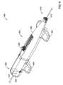
図6は、例示的なアテレクトミイシステム400の斜視図である。場合によってはアテレクトミイシステム400は、アテレクトミイシステム10、20、40、50又は300の具現であると見なし得る。場合によってはアテレクトミイシステム400の特徴は、例えばアテレクトミイシステム10、20、40、50又は300の特徴と組み合わされ得る。アテレクトミイシステム400は、ハンドル402を含む。図示されていないが、アテレクトミイシステム400は、(図1~3に示される駆動機構12のような)駆動機構、及びハンドル402の中に配置されるとともに駆動機構の動作を制御する(図1~2に示されるコントローラ16のような)コントローラを含むことが理解されるであろう。例えばハンドル402は、動作中にハンドル402を平面上に安定させることに役立つ脚404を含み得る。制御機構406は、ハンドル402の外に延びるとともに、使用中にアテレクトミイシステム400の一つ以上の特徴を制御する際に使用され得る。例えば制御機構406は、使用者が駆動機構の動作速度を変更することを許容するために使用され得る。 FIG. 6 is a perspective view of an
ハンドル402は、近位領域408及び遠位領域410を含む。見られるように遠位領域410は、(図2及び4の駆動ケーブル24、又は図5の駆動ケーブル304のような)駆動ケーブルがハンドル402から抜け出すことを可能にするように適合された開口部412を含む。見えないが近位領域408は、アテレクトミイシステム400を通って延びるガイドワイヤ414を収容するように構成され得る。遠位領域410においてガイドワイヤ414は、本図に示されていない駆動ケーブルを通って延びるであろうことが理解されるであろう。 Handle 402 includes a
アテレクトミイシステム400は、図6に鎖線ブロック図にて模式的に示される電気的に作動されるガイドワイヤクランプ420を含む。場合によってはガイドワイヤクランプ420は、ガイドワイヤブレーキとして言及され得ることが理解されるであろう。場合によってはガイドワイヤクランプ420は、電磁ガイドワイヤクランプであり得る。電磁ガイドワイヤクランプ420は、ハンドル402の内部に配置され得るとともに、アテレクトミイシステム400の動作中のガイドワイヤ414の移動を防止するためにガイドワイヤ414を可逆的にしっかりと固定するように構成され得る。電磁ガイドワイヤクランプ420は、ガイドワイヤ414を超えてアテレクトミイシステム400を進めるためにガイドワイヤ414がハンドル420に対して軸線方向に移動することを許容するように構成され得る。電磁ガイドワイヤクランプ420は、それ故に締め付け形態及び締め付け解除形態を有すると見なし得る。言い換えれば電磁ガイドワイヤクランプ420は、締め付け解除形態から締め付け形態へ作動されることができると見なし得る。
場合によってはコントローラ350(図5)は、駆動モータ22、302が動作することを許容する前に、電磁ガイドワイヤクランプ420を自動的に作動するように構成され得る。コントローラ350は、所定の値又は閾値が電磁ガイドワイヤクランプ420にて検出されると、駆動モータ22、302の動作を自動的かつ即座に停止し得る。 In some cases, controller 350 (FIG. 5) may be configured to automatically activate
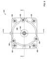
図7は、電磁ガイドワイヤクランプ420の例の斜視図である。図8は、いくつかの断面がどのように採られ得るかを示す電磁ガイドワイヤクランプ420の上面図である。電磁ガイドワイヤクランプ420は、クランプハウジング422を含む。場合によってはクランプハウジング又はガイドワイヤクランプハウジング422は、上部クランプハウジング424及び下部クランプハウジング426を含むと見なし得る。示されるように上部クランプハウジング424及び下部クランプハウジング426は、上部クランプハウジングフランジ432と下部クランプハウジングフランジ434との間に延びる留め具428によって互いに固定されているように示される。場合によっては留め具428は、ネジ、ボルト又はリベットであり得る。場合によっては上部クランプハウジングフランジ432及び下部クランプハウジングフランジ434は、互いに接着して固定され得る。これらは単なる例である。クランプハウジング422は、キャップ436も含む。キャップ436は、留め具438によって上部クランプハウジング424に固定され得る。見られるように留め具440は、キャップ436の中へ下向きに延びる。図9に対して説明されるように留め具440は、電磁ガイドワイヤクランプ420の内部構成要素を固定するために使用され得る。前述した内部構成要素に動作可能に連結される一組の導電体442もまた、図7に示される。 FIG. 7 is a perspective view of an example
図9は、図8の線9-9に沿った電磁ガイドワイヤクランプ420の断面図である。電磁ガイドワイヤクランプ420は、電磁石450及びスチールプランジャ452を含む。電磁石450は、留め具442と電磁石450の中に形成された対応するねじ付き開口部442aとの間の相互作用によって上部クランプハウジング424に対して固定されていると見なし得る。スチールプランジャ452は、下部クランプハウジング426に対して摺動自在に配置されると見なし得る。電磁石450が電気的に励起されていない非作動形態では、電磁石450とスチールプランジャ452との間にガイドワイヤ414(図6)の通路を収容する隙間454が存在する。上部クランプハウジング424及び下部クランプハウジング426は、協働してガイドワイヤ導入部456を形成する。ガイドワイヤ導入部456は、電磁ガイドワイヤクランプ420の中にガイドワイヤ414を延ばすことを、より容易にするために内部に向かって先細にし得る。 FIG. 9 is a cross-sectional view of electromagnetic
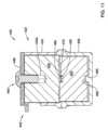
図10は、図8の線10-10に沿った電磁ガイドワイヤクランプ420の断面図である。場合によっては電磁ガイドワイヤクランプ420は、スチールプランジャ452に対向する電磁石450の側面に固定された第一の弾性パッド460、及び電磁石450に面するスチールプランジャ452の側面に固定された第二の弾性パッド462を含み得る。第一の弾性パッド460及び第二の弾性パッド462は、電磁石450が作動されることによってスチールプランジャ452が電磁石450に向かって(図示された配向において)上方に移動する際に、相対的な移動からガイドワイヤ414を固定することを協働して補助し得ることが理解されるであろう。第一及び第二の弾性パッド460、462は、限定されないがシリコーン、ネオプレン、ニトリル、EPFM等のような適切な電気的に絶縁性(非導電性)の材料のいずれかから作製されうる。 FIG. 10 is a cross-sectional view of
図10における図は、図9に示されたものから90度回転されていることが理解されるであろう。この図ではスチールプランジャ452はスチールプランジャ452の上部を横切って延びる凹部470を含むことがみられる。この図では第一の弾性パッド460は、比較的細い長尺片であるとともに第二の弾性462パッドもまた、比較的細い長尺片であることがみられる。さらに第二の弾性パッド462は、凹部470の中に配置されていることがみられるとともに、第一の弾性パッド460は、電磁石450に対して固定されており、凹部470及び第二の弾性パッド462と整列されている。場合によっては示されるように、下部クランプハウジング424は、スチールプランジャ452の中に形成された対応する整列開口部482と整列させる整列ペグ480を規定し得る。整列ペグ480及び整列開口部482は、協働して下部クランプハウジング424に対するスチールプランジャ452の相対的な放射方向の移動を制限し得る。場合によっては整列開口部482は、凹部470と同じ大きさに形成されるため、スチールプランジャ452は、180度離れた二つの縦方向の位置のうちいずれか一方に設置され得ることが熟考される。 It will be appreciated that the view in FIG. 10 has been rotated 90 degrees from that shown in FIG. In this view,
図10は、電磁石450が電気的に作動されていない締め付け解除位置における電磁ガイドワイヤクランプ420を示す。一方、図11は、電磁石450が電気的に作動された締め付け位置における電磁石ガイドワイヤクランプ420を示す。図11を図10と比較することによって見られるようにスチールプランジャ452は、電磁石450に向かって(図示された配向において)上方に移動している。第一の弾性パッド460及び第二の弾性パッド462は共に凹部470を実質的に満たし、それによってガイドワイヤ414(図11に図示なし)をそれらの間に締め付ける。同様に空間は、整列ペグ480とスチールプランジャ452の底に位置する対応する整列開口部482との間に現在視認可能であり、スチールプランジャ452が下部クランプハウジング424に対して移動したことを示している。 FIG. 10 shows
明細書中に説明されるように電磁ガイドワイヤクランプ420は、図10に示される締め付け解除形態へと重力によって付勢されていると見なし得る。電磁石450へ電流を供給することにより、スチールプランジャ452が電磁石450に近づくように移動させられ、従って図11に示される締め付け形態になる。電流を解除することにより、電磁ガイドワイヤクランプ420が締め付け解除形態に戻ることが許容されるであろう。 The
ガイドワイヤクランプを形成する他の方法が熟考される。例えば、ガイドワイヤクランプは、限定されないが、例えば機械的付勢を提供するための一つ以上のばねを使用して、互いに向かって機械的に付勢される二つの電磁石、又は、一つの磁石及び一つの電磁石を含み得る。従って、ガイドワイヤクランプは、締め付け形態へと付勢され得る。二つの磁石を互いに離間するように移動させるために、電流が選択的に両方の電磁石(又は一つの電磁石)に適用され、その結果、磁石が互いに反発し、それによってガイドワイヤクランプが締め付け解除形態に移動するため、ガイドワイヤはそこを通って延ばされる。電流を止めることによって、磁石が再度互いに向かって移動してガイドワイヤを定位置に保持し得る。場合によっては両方の磁石が自由に移動し得るが、他の場合には一つの磁石は定位置に固定され、他方は自由に移動し得る。二つの電磁石、又は、一つの電磁石及び一つの磁石を有するこのようなガイドワイヤクランプは、二つの電磁石の間、又は、電磁石と磁石との間の相対的な移動を容易にするハウジング要素を含み得ることが理解されるであろう。これらは単なる例である。 Other methods of forming guidewire clamps are contemplated. For example, a guidewire clamp may include two electromagnets or a single magnet that are mechanically biased toward each other, such as, but not limited to, using one or more springs to provide the mechanical bias. and one electromagnet. Accordingly, the guidewire clamp may be biased into a clamped configuration. To move the two magnets away from each other, a current is selectively applied to both electromagnets (or one electromagnet), so that the magnets repel each other, thereby causing the guidewire clamp to move into the unclamped configuration. A guidewire is extended therethrough to move the guidewire. By stopping the current, the magnets can move toward each other again to hold the guidewire in place. In some cases both magnets may be free to move, while in other cases one magnet may be fixed in place and the other may be free to move. Such guidewire clamps with two electromagnets, or one electromagnet and one magnet, include a housing element that facilitates relative movement between the two electromagnets or between an electromagnet and a magnet. You will understand what you get. These are just examples.
本開示は、多くの事項に関して、単なる例示であることを理解されるべきである。特に形状、大きさおよび工程の準備に関して、本開示の範囲を逸脱することなく変更が詳細になされ得る。これは、適切な範囲において他の実施形態に使用されている一例の実施形態の特徴のうちいずれかの使用が含まれ得る。本発明の範囲は、もちろん添付の特許請求の範囲が表す言語において規定される。 It should be understood that this disclosure, in many respects, is merely illustrative. Changes may be made in details, particularly with respect to shape, size and process preparation, without departing from the scope of the disclosure. This may include the use of any of the features of the example embodiment that are used in other embodiments to the extent appropriate. The scope of the invention is, of course, defined in the language of the appended claims.
Claims (4)
Translated fromJapaneseアテレクトミイバーと、
前記アテレクトミイバーと連結された駆動ケーブルと、
前記ハンドルハウジング内に配置された駆動モータであって、前記駆動モータから前記アテレクトミイバーまで延びる前記駆動ケーブルによって前記アテレクトミイバーを回転可能に作動させるように適合されるとともに、前記駆動ケーブルがその駆動ケーブルを通って延びるガイドワイヤを収容するように適合された前記駆動モータと、
前記駆動モータの動作を制御するように適合されたコントローラと、
前記駆動ケーブルに対して前記ガイドワイヤを解放可能に固定するように適合された電磁ガイドワイヤクランプとを備え、前記電磁ガイドワイヤクランプは、
電磁石と、
前記電磁石に対して摺動自在に配置されたスチールプランジャであって、そのため前記スチールプランジャは、前記電磁石が作動された時に前記電磁石へ向かって移動できるとともに前記電磁石と前記スチールプランジャとの間で前記ガイドワイヤを締め付ける前記スチールプランジャを含む、アテレクトミイシステム。a handle including a handle housing;
Aterectomiver and
a drive cable connected to the atherectomy bar;
a drive motor disposed within the handle housing, the drive motor being adapted to rotatably actuate the atherosclerosis bar by the drive cable extending from the drive motor to the atherosclerotic bar; the drive motor being adapted to accommodate a guide wire extending through the drive cable;
a controller adapted to control operation of the drive motor;
an electromagnetic guidewire clamp adapted to releasably secure the guidewire to the drive cable, the electromagnetic guidewire clamp comprising:
electromagnet and
a steel plunger slidably disposed relative to the electromagnet, such that the steel plunger is movable towards the electromagnet when the electromagnet is actuated and between the electromagnet and the steel plunger; An atherectomy system including said steel plunger that tightens the guide wire.
前記スチールプランジャを収容するように適合された下部クランプハウジングと、
前記電磁石を収容するように適合された上部クランプハウジングとを含む、請求項2に記載のアテレクトミイシステム。The electromagnetic guide wire clamp housing includes:
a lower clamp housing adapted to accommodate the steel plunger;
3. The atherectomy system of claim2 , including an upper clamp housing adapted to house the electromagnet.
前記アテレクトミイバーを回転可能に作動させるように適合された駆動機構であって、前記駆動機構はそれを通って延びるガイドワイヤを収容するように適合された前記駆動機構と、
前記駆動機構の動作を制御するように適合されたコントローラと、
前記駆動機構を通って延びるガイドワイヤと、
前記駆動機構に対して前記ガイドワイヤを解放可能に固定するように適合された電気的に作動されるガイドワイヤクランプであって、
電磁石、および
前記電磁石に対して摺動自在に配置されたスチールプランジャを備え、前記スチールプランジャは、前記電磁石が作動された時に前記電磁石へ向かって移動できるとともに前記電磁石と前記スチールプランジャとの間で前記ガイドワイヤを締め付けるスチールプランジャを備えるガイドワイヤクランプとを備える、アテレクトミイシステム。Aterectomiver and
a drive mechanism adapted to rotatably actuate the atherectomy bar, the drive mechanism adapted to receive a guidewire extending therethrough;
a controller adapted to control operation of the drive mechanism;
a guidewire extending through the drive mechanism;
an electrically actuated guidewire clamp adapted to releasably secure the guidewire relative to the drive mechanism;
an electromagnet; and a steel plunger slidably disposed relative to the electromagnet, the steel plunger being movable towards the electromagnet and between the electromagnet and the steel plunger when the electromagnet is actuated. a guidewire clamp having a steel plunger for tightening the guidewire.
Applications Claiming Priority (3)
| Application Number | Priority Date | Filing Date | Title |
|---|---|---|---|
| US201962899623P | 2019-09-12 | 2019-09-12 | |
| US62/899,623 | 2019-09-12 | ||
| PCT/US2020/049999WO2021050592A1 (en) | 2019-09-12 | 2020-09-09 | Atherectomy system with electromagnetic guidewire clamp |
Publications (2)
| Publication Number | Publication Date |
|---|---|
| JP2022548587A JP2022548587A (en) | 2022-11-21 |
| JP7400085B2true JP7400085B2 (en) | 2023-12-18 |
Family
ID=72562035
Family Applications (1)
| Application Number | Title | Priority Date | Filing Date |
|---|---|---|---|
| JP2022516170AActiveJP7400085B2 (en) | 2019-09-12 | 2020-09-09 | Atherectomy system using electromagnetic guide wire clamp |
Country Status (5)
| Country | Link |
|---|---|
| US (2) | US11744608B2 (en) |
| EP (1) | EP3998970A1 (en) |
| JP (1) | JP7400085B2 (en) |
| CN (1) | CN114364332B (en) |
| WO (1) | WO2021050592A1 (en) |
Families Citing this family (2)
| Publication number | Priority date | Publication date | Assignee | Title |
|---|---|---|---|---|
| US20230069219A1 (en)* | 2021-08-27 | 2023-03-02 | Boston Scientific Scimed, Inc. | Atherectomy system with anterograde and retrograde ablation |
| CN116250899A (en)* | 2021-12-10 | 2023-06-13 | 上海鸿脉医疗科技有限公司 | Rotary grinding system and rotary grinding control handle thereof |
Citations (3)
| Publication number | Priority date | Publication date | Assignee | Title |
|---|---|---|---|---|
| JP2004514463A (en) | 2000-04-05 | 2004-05-20 | エスティーエックス メディカル インコーポレイテッド | Tube material removal system and method |
| US20070293719A1 (en) | 2006-06-20 | 2007-12-20 | Boston Scientific Scimed, Inc. | Medical device for use in endoscopic procedure |
| CN207980153U (en) | 2017-07-06 | 2018-10-19 | 北京理工大学 | A kind of intervention operation catheter guide wire control device |
Family Cites Families (13)
| Publication number | Priority date | Publication date | Assignee | Title |
|---|---|---|---|---|
| FR58301E (en)* | 1948-05-14 | 1953-11-18 | Further training in the looms | |
| GB921312A (en)* | 1960-11-25 | 1963-03-20 | Cincinnati Milling Machine Co | Machine tool loader |
| US4037704A (en)* | 1975-07-03 | 1977-07-26 | Ncr Corporation | Actuator for a wire matrix printer and method of making |
| US4330104A (en)* | 1979-01-23 | 1982-05-18 | Henri Klok | Hydraulic jack and stand combination with key and hinged handle |
| US5318576A (en) | 1992-12-16 | 1994-06-07 | Plassche Jr Walter M | Endovascular surgery systems |
| US5893857A (en) | 1997-01-21 | 1999-04-13 | Shturman Cardiology Systems, Inc. | Handle for atherectomy device |
| US6149663A (en)* | 1999-08-17 | 2000-11-21 | Scimed Life Systems, Inc. | Guide wire brake for ablation assembly |
| AU2001270790A1 (en)* | 2000-07-11 | 2002-01-21 | Dall Vagn-Erik | Gripping devices |
| US6503227B1 (en)* | 2000-07-24 | 2003-01-07 | Scimed Life Systems, Inc. | Guide wire brake |
| US20070270688A1 (en)* | 2006-05-19 | 2007-11-22 | Daniel Gelbart | Automatic atherectomy system |
| CN101209209B (en)* | 2006-12-30 | 2010-06-16 | Ge医疗系统环球技术有限公司 | Radiation photography system |
| KR20100086103A (en)* | 2009-01-22 | 2010-07-30 | 서울대학교산학협력단 | A rotational atherectomy burr for ablating chronic total occlusion and the ablation apparatus using the same |
| CA2953631A1 (en)* | 2017-01-05 | 2018-07-05 | Eric Robert | Hair braiding machine to perform three-stranded braids |
- 2020
- 2020-09-09EPEP20775558.8Apatent/EP3998970A1/enactivePending
- 2020-09-09CNCN202080063947.0Apatent/CN114364332B/enactiveActive
- 2020-09-09JPJP2022516170Apatent/JP7400085B2/enactiveActive
- 2020-09-09USUS17/016,173patent/US11744608B2/enactiveActive
- 2020-09-09WOPCT/US2020/049999patent/WO2021050592A1/ennot_activeCeased
- 2023
- 2023-07-26USUS18/226,583patent/US20230363789A1/enactivePending
Patent Citations (3)
| Publication number | Priority date | Publication date | Assignee | Title |
|---|---|---|---|---|
| JP2004514463A (en) | 2000-04-05 | 2004-05-20 | エスティーエックス メディカル インコーポレイテッド | Tube material removal system and method |
| US20070293719A1 (en) | 2006-06-20 | 2007-12-20 | Boston Scientific Scimed, Inc. | Medical device for use in endoscopic procedure |
| CN207980153U (en) | 2017-07-06 | 2018-10-19 | 北京理工大学 | A kind of intervention operation catheter guide wire control device |
Also Published As
| Publication number | Publication date |
|---|---|
| CN114364332B (en) | 2025-01-21 |
| WO2021050592A1 (en) | 2021-03-18 |
| US20230363789A1 (en) | 2023-11-16 |
| CN114364332A (en) | 2022-04-15 |
| US20210077143A1 (en) | 2021-03-18 |
| EP3998970A1 (en) | 2022-05-25 |
| US11744608B2 (en) | 2023-09-05 |
| JP2022548587A (en) | 2022-11-21 |
Similar Documents
| Publication | Publication Date | Title |
|---|---|---|
| US20230363789A1 (en) | Atherectomy system with electromagnetic guidewire clamp | |
| US11696782B2 (en) | Rotational medical device | |
| US12213697B2 (en) | Atherectomy system adapted to free a stuck atherectomy burr | |
| US20250176993A1 (en) | Atherectomy system with excess torque protection | |
| ATE405226T1 (en) | INTERVENTION CATHETER WITH DIFFERENT CUTTING SURFACES | |
| US12369942B2 (en) | Atherectomy system with guidewire detection | |
| US12295614B2 (en) | High power atherectomy with multiple safety limits | |
| JP7386249B2 (en) | Atherectomy motor control system |
Legal Events
| Date | Code | Title | Description |
|---|---|---|---|
| A621 | Written request for application examination | Free format text:JAPANESE INTERMEDIATE CODE: A621 Effective date:20220323 | |
| A131 | Notification of reasons for refusal | Free format text:JAPANESE INTERMEDIATE CODE: A131 Effective date:20230104 | |
| A521 | Request for written amendment filed | Free format text:JAPANESE INTERMEDIATE CODE: A523 Effective date:20230403 | |
| A02 | Decision of refusal | Free format text:JAPANESE INTERMEDIATE CODE: A02 Effective date:20230516 | |
| A521 | Request for written amendment filed | Free format text:JAPANESE INTERMEDIATE CODE: A523 Effective date:20230915 | |
| A911 | Transfer to examiner for re-examination before appeal (zenchi) | Free format text:JAPANESE INTERMEDIATE CODE: A911 Effective date:20230926 | |
| TRDD | Decision of grant or rejection written | ||
| A01 | Written decision to grant a patent or to grant a registration (utility model) | Free format text:JAPANESE INTERMEDIATE CODE: A01 Effective date:20231107 | |
| A61 | First payment of annual fees (during grant procedure) | Free format text:JAPANESE INTERMEDIATE CODE: A61 Effective date:20231206 | |
| R150 | Certificate of patent or registration of utility model | Ref document number:7400085 Country of ref document:JP Free format text:JAPANESE INTERMEDIATE CODE: R150 |