JP7395715B2 - solar powered display assembly - Google Patents
solar powered display assemblyDownload PDFInfo
- Publication number
- JP7395715B2 JP7395715B2JP2022513050AJP2022513050AJP7395715B2JP 7395715 B2JP7395715 B2JP 7395715B2JP 2022513050 AJP2022513050 AJP 2022513050AJP 2022513050 AJP2022513050 AJP 2022513050AJP 7395715 B2JP7395715 B2JP 7395715B2
- Authority
- JP
- Japan
- Prior art keywords
- solar energy
- energy harvesting
- power
- harvesting device
- housing
- Prior art date
- Legal status (The legal status is an assumption and is not a legal conclusion. Google has not performed a legal analysis and makes no representation as to the accuracy of the status listed.)
- Active
Links
Images


Classifications
- G—PHYSICS
- G09—EDUCATION; CRYPTOGRAPHY; DISPLAY; ADVERTISING; SEALS
- G09F—DISPLAYING; ADVERTISING; SIGNS; LABELS OR NAME-PLATES; SEALS
- G09F27/00—Combined visual and audible advertising or displaying, e.g. for public address
- G09F27/007—Displays with power supply provided by solar cells or photocells
- B—PERFORMING OPERATIONS; TRANSPORTING
- B60—VEHICLES IN GENERAL
- B60K—ARRANGEMENT OR MOUNTING OF PROPULSION UNITS OR OF TRANSMISSIONS IN VEHICLES; ARRANGEMENT OR MOUNTING OF PLURAL DIVERSE PRIME-MOVERS IN VEHICLES; AUXILIARY DRIVES FOR VEHICLES; INSTRUMENTATION OR DASHBOARDS FOR VEHICLES; ARRANGEMENTS IN CONNECTION WITH COOLING, AIR INTAKE, GAS EXHAUST OR FUEL SUPPLY OF PROPULSION UNITS IN VEHICLES
- B60K6/00—Arrangement or mounting of plural diverse prime-movers for mutual or common propulsion, e.g. hybrid propulsion systems comprising electric motors and internal combustion engines
- B60K6/20—Arrangement or mounting of plural diverse prime-movers for mutual or common propulsion, e.g. hybrid propulsion systems comprising electric motors and internal combustion engines the prime-movers consisting of electric motors and internal combustion engines, e.g. HEVs
- B60K6/22—Arrangement or mounting of plural diverse prime-movers for mutual or common propulsion, e.g. hybrid propulsion systems comprising electric motors and internal combustion engines the prime-movers consisting of electric motors and internal combustion engines, e.g. HEVs characterised by apparatus, components or means specially adapted for HEVs
- B60K6/24—Arrangement or mounting of plural diverse prime-movers for mutual or common propulsion, e.g. hybrid propulsion systems comprising electric motors and internal combustion engines the prime-movers consisting of electric motors and internal combustion engines, e.g. HEVs characterised by apparatus, components or means specially adapted for HEVs characterised by the combustion engines
- B—PERFORMING OPERATIONS; TRANSPORTING
- B60—VEHICLES IN GENERAL
- B60K—ARRANGEMENT OR MOUNTING OF PROPULSION UNITS OR OF TRANSMISSIONS IN VEHICLES; ARRANGEMENT OR MOUNTING OF PLURAL DIVERSE PRIME-MOVERS IN VEHICLES; AUXILIARY DRIVES FOR VEHICLES; INSTRUMENTATION OR DASHBOARDS FOR VEHICLES; ARRANGEMENTS IN CONNECTION WITH COOLING, AIR INTAKE, GAS EXHAUST OR FUEL SUPPLY OF PROPULSION UNITS IN VEHICLES
- B60K6/00—Arrangement or mounting of plural diverse prime-movers for mutual or common propulsion, e.g. hybrid propulsion systems comprising electric motors and internal combustion engines
- B60K6/20—Arrangement or mounting of plural diverse prime-movers for mutual or common propulsion, e.g. hybrid propulsion systems comprising electric motors and internal combustion engines the prime-movers consisting of electric motors and internal combustion engines, e.g. HEVs
- B60K6/22—Arrangement or mounting of plural diverse prime-movers for mutual or common propulsion, e.g. hybrid propulsion systems comprising electric motors and internal combustion engines the prime-movers consisting of electric motors and internal combustion engines, e.g. HEVs characterised by apparatus, components or means specially adapted for HEVs
- B60K6/26—Arrangement or mounting of plural diverse prime-movers for mutual or common propulsion, e.g. hybrid propulsion systems comprising electric motors and internal combustion engines the prime-movers consisting of electric motors and internal combustion engines, e.g. HEVs characterised by apparatus, components or means specially adapted for HEVs characterised by the motors or the generators
- B—PERFORMING OPERATIONS; TRANSPORTING
- B60—VEHICLES IN GENERAL
- B60K—ARRANGEMENT OR MOUNTING OF PROPULSION UNITS OR OF TRANSMISSIONS IN VEHICLES; ARRANGEMENT OR MOUNTING OF PLURAL DIVERSE PRIME-MOVERS IN VEHICLES; AUXILIARY DRIVES FOR VEHICLES; INSTRUMENTATION OR DASHBOARDS FOR VEHICLES; ARRANGEMENTS IN CONNECTION WITH COOLING, AIR INTAKE, GAS EXHAUST OR FUEL SUPPLY OF PROPULSION UNITS IN VEHICLES
- B60K6/00—Arrangement or mounting of plural diverse prime-movers for mutual or common propulsion, e.g. hybrid propulsion systems comprising electric motors and internal combustion engines
- B60K6/20—Arrangement or mounting of plural diverse prime-movers for mutual or common propulsion, e.g. hybrid propulsion systems comprising electric motors and internal combustion engines the prime-movers consisting of electric motors and internal combustion engines, e.g. HEVs
- B60K6/22—Arrangement or mounting of plural diverse prime-movers for mutual or common propulsion, e.g. hybrid propulsion systems comprising electric motors and internal combustion engines the prime-movers consisting of electric motors and internal combustion engines, e.g. HEVs characterised by apparatus, components or means specially adapted for HEVs
- B60K6/28—Arrangement or mounting of plural diverse prime-movers for mutual or common propulsion, e.g. hybrid propulsion systems comprising electric motors and internal combustion engines the prime-movers consisting of electric motors and internal combustion engines, e.g. HEVs characterised by apparatus, components or means specially adapted for HEVs characterised by the electric energy storing means, e.g. batteries or capacitors
- B—PERFORMING OPERATIONS; TRANSPORTING
- B60—VEHICLES IN GENERAL
- B60L—PROPULSION OF ELECTRICALLY-PROPELLED VEHICLES; SUPPLYING ELECTRIC POWER FOR AUXILIARY EQUIPMENT OF ELECTRICALLY-PROPELLED VEHICLES; ELECTRODYNAMIC BRAKE SYSTEMS FOR VEHICLES IN GENERAL; MAGNETIC SUSPENSION OR LEVITATION FOR VEHICLES; MONITORING OPERATING VARIABLES OF ELECTRICALLY-PROPELLED VEHICLES; ELECTRIC SAFETY DEVICES FOR ELECTRICALLY-PROPELLED VEHICLES
- B60L58/00—Methods or circuit arrangements for monitoring or controlling batteries or fuel cells, specially adapted for electric vehicles
- B60L58/10—Methods or circuit arrangements for monitoring or controlling batteries or fuel cells, specially adapted for electric vehicles for monitoring or controlling batteries
- B—PERFORMING OPERATIONS; TRANSPORTING
- B60—VEHICLES IN GENERAL
- B60R—VEHICLES, VEHICLE FITTINGS, OR VEHICLE PARTS, NOT OTHERWISE PROVIDED FOR
- B60R11/00—Arrangements for holding or mounting articles, not otherwise provided for
- B60R11/02—Arrangements for holding or mounting articles, not otherwise provided for for radio sets, television sets, telephones, or the like; Arrangement of controls thereof
- B60R11/0229—Arrangements for holding or mounting articles, not otherwise provided for for radio sets, television sets, telephones, or the like; Arrangement of controls thereof for displays, e.g. cathodic tubes
- B60R11/0235—Arrangements for holding or mounting articles, not otherwise provided for for radio sets, television sets, telephones, or the like; Arrangement of controls thereof for displays, e.g. cathodic tubes of flat type, e.g. LCD
- B—PERFORMING OPERATIONS; TRANSPORTING
- B60—VEHICLES IN GENERAL
- B60R—VEHICLES, VEHICLE FITTINGS, OR VEHICLE PARTS, NOT OTHERWISE PROVIDED FOR
- B60R13/00—Elements for body-finishing, identifying, or decorating; Arrangements or adaptations for advertising purposes
- B—PERFORMING OPERATIONS; TRANSPORTING
- B60—VEHICLES IN GENERAL
- B60R—VEHICLES, VEHICLE FITTINGS, OR VEHICLE PARTS, NOT OTHERWISE PROVIDED FOR
- B60R16/00—Electric or fluid circuits specially adapted for vehicles and not otherwise provided for; Arrangement of elements of electric or fluid circuits specially adapted for vehicles and not otherwise provided for
- B60R16/02—Electric or fluid circuits specially adapted for vehicles and not otherwise provided for; Arrangement of elements of electric or fluid circuits specially adapted for vehicles and not otherwise provided for electric constitutive elements
- B60R16/03—Electric or fluid circuits specially adapted for vehicles and not otherwise provided for; Arrangement of elements of electric or fluid circuits specially adapted for vehicles and not otherwise provided for electric constitutive elements for supply of electrical power to vehicle subsystems or for
- B60R16/033—Electric or fluid circuits specially adapted for vehicles and not otherwise provided for; Arrangement of elements of electric or fluid circuits specially adapted for vehicles and not otherwise provided for electric constitutive elements for supply of electrical power to vehicle subsystems or for characterised by the use of electrical cells or batteries
- B—PERFORMING OPERATIONS; TRANSPORTING
- B60—VEHICLES IN GENERAL
- B60R—VEHICLES, VEHICLE FITTINGS, OR VEHICLE PARTS, NOT OTHERWISE PROVIDED FOR
- B60R9/00—Supplementary fittings on vehicle exterior for carrying loads, e.g. luggage, sports gear or the like
- B60R9/04—Carriers associated with vehicle roof
- E—FIXED CONSTRUCTIONS
- E04—BUILDING
- E04H—BUILDINGS OR LIKE STRUCTURES FOR PARTICULAR PURPOSES; SWIMMING OR SPLASH BATHS OR POOLS; MASTS; FENCING; TENTS OR CANOPIES, IN GENERAL
- E04H1/00—Buildings or groups of buildings for dwelling or office purposes; General layout, e.g. modular co-ordination or staggered storeys
- E04H1/12—Small buildings or other erections for limited occupation, erected in the open air or arranged in buildings, e.g. kiosks, waiting shelters for bus stops or for filling stations, roofs for railway platforms, watchmen's huts or dressing cubicles
- E04H1/1205—Small buildings erected in the open air
- E04H1/1211—Waiting shelters for bus stops
- G—PHYSICS
- G09—EDUCATION; CRYPTOGRAPHY; DISPLAY; ADVERTISING; SEALS
- G09F—DISPLAYING; ADVERTISING; SIGNS; LABELS OR NAME-PLATES; SEALS
- G09F15/00—Boards, hoardings, pillars, or like structures for notices, placards, posters, or the like
- G09F15/0006—Boards, hoardings, pillars, or like structures for notices, placards, posters, or the like planar structures comprising one or more panels
- G09F15/0037—Boards, hoardings, pillars, or like structures for notices, placards, posters, or the like planar structures comprising one or more panels supported by a post
- G—PHYSICS
- G09—EDUCATION; CRYPTOGRAPHY; DISPLAY; ADVERTISING; SEALS
- G09F—DISPLAYING; ADVERTISING; SIGNS; LABELS OR NAME-PLATES; SEALS
- G09F15/00—Boards, hoardings, pillars, or like structures for notices, placards, posters, or the like
- G09F15/0006—Boards, hoardings, pillars, or like structures for notices, placards, posters, or the like planar structures comprising one or more panels
- G09F15/005—Boards, hoardings, pillars, or like structures for notices, placards, posters, or the like planar structures comprising one or more panels for orientation or public information
- G—PHYSICS
- G09—EDUCATION; CRYPTOGRAPHY; DISPLAY; ADVERTISING; SEALS
- G09F—DISPLAYING; ADVERTISING; SIGNS; LABELS OR NAME-PLATES; SEALS
- G09F19/00—Advertising or display means not otherwise provided for
- G09F19/22—Advertising or display means on roads, walls or similar surfaces, e.g. illuminated
- G—PHYSICS
- G09—EDUCATION; CRYPTOGRAPHY; DISPLAY; ADVERTISING; SEALS
- G09F—DISPLAYING; ADVERTISING; SIGNS; LABELS OR NAME-PLATES; SEALS
- G09F21/00—Mobile visual advertising
- G09F21/04—Mobile visual advertising by land vehicles
- G—PHYSICS
- G09—EDUCATION; CRYPTOGRAPHY; DISPLAY; ADVERTISING; SEALS
- G09F—DISPLAYING; ADVERTISING; SIGNS; LABELS OR NAME-PLATES; SEALS
- G09F21/00—Mobile visual advertising
- G09F21/04—Mobile visual advertising by land vehicles
- G09F21/042—Mobile visual advertising by land vehicles the advertising matter being fixed on the roof of the vehicles
- G—PHYSICS
- G09—EDUCATION; CRYPTOGRAPHY; DISPLAY; ADVERTISING; SEALS
- G09F—DISPLAYING; ADVERTISING; SIGNS; LABELS OR NAME-PLATES; SEALS
- G09F9/00—Indicating arrangements for variable information in which the information is built-up on a support by selection or combination of individual elements
- G09F9/30—Indicating arrangements for variable information in which the information is built-up on a support by selection or combination of individual elements in which the desired character or characters are formed by combining individual elements
- G09F9/33—Indicating arrangements for variable information in which the information is built-up on a support by selection or combination of individual elements in which the desired character or characters are formed by combining individual elements being semiconductor devices, e.g. diodes
- H—ELECTRICITY
- H02—GENERATION; CONVERSION OR DISTRIBUTION OF ELECTRIC POWER
- H02J—CIRCUIT ARRANGEMENTS OR SYSTEMS FOR SUPPLYING OR DISTRIBUTING ELECTRIC POWER; SYSTEMS FOR STORING ELECTRIC ENERGY
- H02J3/00—Circuit arrangements for AC mains or AC distribution networks
- H02J3/38—Arrangements for parallely feeding a single network by two or more generators, converters or transformers
- H02J3/381—Dispersed generators
- H—ELECTRICITY
- H02—GENERATION; CONVERSION OR DISTRIBUTION OF ELECTRIC POWER
- H02J—CIRCUIT ARRANGEMENTS OR SYSTEMS FOR SUPPLYING OR DISTRIBUTING ELECTRIC POWER; SYSTEMS FOR STORING ELECTRIC ENERGY
- H02J7/00—Circuit arrangements for charging or depolarising batteries or for supplying loads from batteries
- H02J7/0068—Battery or charger load switching, e.g. concurrent charging and load supply
- H—ELECTRICITY
- H02—GENERATION; CONVERSION OR DISTRIBUTION OF ELECTRIC POWER
- H02J—CIRCUIT ARRANGEMENTS OR SYSTEMS FOR SUPPLYING OR DISTRIBUTING ELECTRIC POWER; SYSTEMS FOR STORING ELECTRIC ENERGY
- H02J7/00—Circuit arrangements for charging or depolarising batteries or for supplying loads from batteries
- H02J7/34—Parallel operation in networks using both storage and other DC sources, e.g. providing buffering
- H02J7/35—Parallel operation in networks using both storage and other DC sources, e.g. providing buffering with light sensitive cells
- H—ELECTRICITY
- H02—GENERATION; CONVERSION OR DISTRIBUTION OF ELECTRIC POWER
- H02S—GENERATION OF ELECTRIC POWER BY CONVERSION OF INFRARED RADIATION, VISIBLE LIGHT OR ULTRAVIOLET LIGHT, e.g. USING PHOTOVOLTAIC [PV] MODULES
- H02S10/00—PV power plants; Combinations of PV energy systems with other systems for the generation of electric power
- H02S10/40—Mobile PV generator systems
- H—ELECTRICITY
- H02—GENERATION; CONVERSION OR DISTRIBUTION OF ELECTRIC POWER
- H02S—GENERATION OF ELECTRIC POWER BY CONVERSION OF INFRARED RADIATION, VISIBLE LIGHT OR ULTRAVIOLET LIGHT, e.g. USING PHOTOVOLTAIC [PV] MODULES
- H02S20/00—Supporting structures for PV modules
- H02S20/10—Supporting structures directly fixed to the ground
- H—ELECTRICITY
- H02—GENERATION; CONVERSION OR DISTRIBUTION OF ELECTRIC POWER
- H02S—GENERATION OF ELECTRIC POWER BY CONVERSION OF INFRARED RADIATION, VISIBLE LIGHT OR ULTRAVIOLET LIGHT, e.g. USING PHOTOVOLTAIC [PV] MODULES
- H02S20/00—Supporting structures for PV modules
- H02S20/20—Supporting structures directly fixed to an immovable object
- H02S20/22—Supporting structures directly fixed to an immovable object specially adapted for buildings
- H02S20/23—Supporting structures directly fixed to an immovable object specially adapted for buildings specially adapted for roof structures
- H—ELECTRICITY
- H02—GENERATION; CONVERSION OR DISTRIBUTION OF ELECTRIC POWER
- H02S—GENERATION OF ELECTRIC POWER BY CONVERSION OF INFRARED RADIATION, VISIBLE LIGHT OR ULTRAVIOLET LIGHT, e.g. USING PHOTOVOLTAIC [PV] MODULES
- H02S20/00—Supporting structures for PV modules
- H02S20/30—Supporting structures being movable or adjustable, e.g. for angle adjustment
- H—ELECTRICITY
- H02—GENERATION; CONVERSION OR DISTRIBUTION OF ELECTRIC POWER
- H02S—GENERATION OF ELECTRIC POWER BY CONVERSION OF INFRARED RADIATION, VISIBLE LIGHT OR ULTRAVIOLET LIGHT, e.g. USING PHOTOVOLTAIC [PV] MODULES
- H02S30/00—Structural details of PV modules other than those related to light conversion
- H02S30/10—Frame structures
- H—ELECTRICITY
- H02—GENERATION; CONVERSION OR DISTRIBUTION OF ELECTRIC POWER
- H02S—GENERATION OF ELECTRIC POWER BY CONVERSION OF INFRARED RADIATION, VISIBLE LIGHT OR ULTRAVIOLET LIGHT, e.g. USING PHOTOVOLTAIC [PV] MODULES
- H02S40/00—Components or accessories in combination with PV modules, not provided for in groups H02S10/00 - H02S30/00
- H02S40/30—Electrical components
- H02S40/38—Energy storage means, e.g. batteries, structurally associated with PV modules
- H—ELECTRICITY
- H02—GENERATION; CONVERSION OR DISTRIBUTION OF ELECTRIC POWER
- H02S—GENERATION OF ELECTRIC POWER BY CONVERSION OF INFRARED RADIATION, VISIBLE LIGHT OR ULTRAVIOLET LIGHT, e.g. USING PHOTOVOLTAIC [PV] MODULES
- H02S40/00—Components or accessories in combination with PV modules, not provided for in groups H02S10/00 - H02S30/00
- H02S40/40—Thermal components
- H02S40/42—Cooling means
- H02S40/425—Cooling means using a gaseous or a liquid coolant, e.g. air flow ventilation, water circulation
- H—ELECTRICITY
- H05—ELECTRIC TECHNIQUES NOT OTHERWISE PROVIDED FOR
- H05K—PRINTED CIRCUITS; CASINGS OR CONSTRUCTIONAL DETAILS OF ELECTRIC APPARATUS; MANUFACTURE OF ASSEMBLAGES OF ELECTRICAL COMPONENTS
- H05K5/00—Casings, cabinets or drawers for electric apparatus
- H05K5/0017—Casings, cabinets or drawers for electric apparatus with operator interface units
- H—ELECTRICITY
- H05—ELECTRIC TECHNIQUES NOT OTHERWISE PROVIDED FOR
- H05K—PRINTED CIRCUITS; CASINGS OR CONSTRUCTIONAL DETAILS OF ELECTRIC APPARATUS; MANUFACTURE OF ASSEMBLAGES OF ELECTRICAL COMPONENTS
- H05K7/00—Constructional details common to different types of electric apparatus
- H05K7/20—Modifications to facilitate cooling, ventilating, or heating
- H05K7/20009—Modifications to facilitate cooling, ventilating, or heating using a gaseous coolant in electronic enclosures
- H05K7/20136—Forced ventilation, e.g. by fans
- H05K7/20172—Fan mounting or fan specifications
- H—ELECTRICITY
- H05—ELECTRIC TECHNIQUES NOT OTHERWISE PROVIDED FOR
- H05K—PRINTED CIRCUITS; CASINGS OR CONSTRUCTIONAL DETAILS OF ELECTRIC APPARATUS; MANUFACTURE OF ASSEMBLAGES OF ELECTRICAL COMPONENTS
- H05K7/00—Constructional details common to different types of electric apparatus
- H05K7/20—Modifications to facilitate cooling, ventilating, or heating
- H05K7/20009—Modifications to facilitate cooling, ventilating, or heating using a gaseous coolant in electronic enclosures
- H05K7/202—Air circulating in closed loop within enclosure wherein heat is removed through heat-exchangers
- H—ELECTRICITY
- H05—ELECTRIC TECHNIQUES NOT OTHERWISE PROVIDED FOR
- H05K—PRINTED CIRCUITS; CASINGS OR CONSTRUCTIONAL DETAILS OF ELECTRIC APPARATUS; MANUFACTURE OF ASSEMBLAGES OF ELECTRICAL COMPONENTS
- H05K7/00—Constructional details common to different types of electric apparatus
- H05K7/20—Modifications to facilitate cooling, ventilating, or heating
- H05K7/20954—Modifications to facilitate cooling, ventilating, or heating for display panels
- H05K7/20972—Forced ventilation, e.g. on heat dissipaters coupled to components
- B—PERFORMING OPERATIONS; TRANSPORTING
- B60—VEHICLES IN GENERAL
- B60R—VEHICLES, VEHICLE FITTINGS, OR VEHICLE PARTS, NOT OTHERWISE PROVIDED FOR
- B60R11/00—Arrangements for holding or mounting articles, not otherwise provided for
- B60R2011/0001—Arrangements for holding or mounting articles, not otherwise provided for characterised by position
- B60R2011/004—Arrangements for holding or mounting articles, not otherwise provided for characterised by position outside the vehicle
- B—PERFORMING OPERATIONS; TRANSPORTING
- B60—VEHICLES IN GENERAL
- B60Y—INDEXING SCHEME RELATING TO ASPECTS CROSS-CUTTING VEHICLE TECHNOLOGY
- B60Y2300/00—Purposes or special features of road vehicle drive control systems
- B60Y2300/91—Battery charging
- B—PERFORMING OPERATIONS; TRANSPORTING
- B60—VEHICLES IN GENERAL
- B60Y—INDEXING SCHEME RELATING TO ASPECTS CROSS-CUTTING VEHICLE TECHNOLOGY
- B60Y2400/00—Special features of vehicle units
- B60Y2400/11—Electric energy storages
- B60Y2400/112—Batteries
- B—PERFORMING OPERATIONS; TRANSPORTING
- B60—VEHICLES IN GENERAL
- B60Y—INDEXING SCHEME RELATING TO ASPECTS CROSS-CUTTING VEHICLE TECHNOLOGY
- B60Y2400/00—Special features of vehicle units
- B60Y2400/43—Engines
- B—PERFORMING OPERATIONS; TRANSPORTING
- B60—VEHICLES IN GENERAL
- B60Y—INDEXING SCHEME RELATING TO ASPECTS CROSS-CUTTING VEHICLE TECHNOLOGY
- B60Y2400/00—Special features of vehicle units
- B60Y2400/60—Electric Machines, e.g. motors or generators
- G—PHYSICS
- G09—EDUCATION; CRYPTOGRAPHY; DISPLAY; ADVERTISING; SEALS
- G09F—DISPLAYING; ADVERTISING; SIGNS; LABELS OR NAME-PLATES; SEALS
- G09F9/00—Indicating arrangements for variable information in which the information is built-up on a support by selection or combination of individual elements
- G09F9/30—Indicating arrangements for variable information in which the information is built-up on a support by selection or combination of individual elements in which the desired character or characters are formed by combining individual elements
- G09F9/35—Indicating arrangements for variable information in which the information is built-up on a support by selection or combination of individual elements in which the desired character or characters are formed by combining individual elements being liquid crystals
- H—ELECTRICITY
- H02—GENERATION; CONVERSION OR DISTRIBUTION OF ELECTRIC POWER
- H02J—CIRCUIT ARRANGEMENTS OR SYSTEMS FOR SUPPLYING OR DISTRIBUTING ELECTRIC POWER; SYSTEMS FOR STORING ELECTRIC ENERGY
- H02J2300/00—Systems for supplying or distributing electric power characterised by decentralized, dispersed, or local generation
- H02J2300/20—The dispersed energy generation being of renewable origin
- H02J2300/22—The renewable source being solar energy
- H02J2300/24—The renewable source being solar energy of photovoltaic origin
- Y—GENERAL TAGGING OF NEW TECHNOLOGICAL DEVELOPMENTS; GENERAL TAGGING OF CROSS-SECTIONAL TECHNOLOGIES SPANNING OVER SEVERAL SECTIONS OF THE IPC; TECHNICAL SUBJECTS COVERED BY FORMER USPC CROSS-REFERENCE ART COLLECTIONS [XRACs] AND DIGESTS
- Y02—TECHNOLOGIES OR APPLICATIONS FOR MITIGATION OR ADAPTATION AGAINST CLIMATE CHANGE
- Y02B—CLIMATE CHANGE MITIGATION TECHNOLOGIES RELATED TO BUILDINGS, e.g. HOUSING, HOUSE APPLIANCES OR RELATED END-USER APPLICATIONS
- Y02B10/00—Integration of renewable energy sources in buildings
- Y02B10/10—Photovoltaic [PV]
- Y—GENERAL TAGGING OF NEW TECHNOLOGICAL DEVELOPMENTS; GENERAL TAGGING OF CROSS-SECTIONAL TECHNOLOGIES SPANNING OVER SEVERAL SECTIONS OF THE IPC; TECHNICAL SUBJECTS COVERED BY FORMER USPC CROSS-REFERENCE ART COLLECTIONS [XRACs] AND DIGESTS
- Y02—TECHNOLOGIES OR APPLICATIONS FOR MITIGATION OR ADAPTATION AGAINST CLIMATE CHANGE
- Y02E—REDUCTION OF GREENHOUSE GAS [GHG] EMISSIONS, RELATED TO ENERGY GENERATION, TRANSMISSION OR DISTRIBUTION
- Y02E10/00—Energy generation through renewable energy sources
- Y02E10/50—Photovoltaic [PV] energy
- Y02E10/56—Power conversion systems, e.g. maximum power point trackers
- Y—GENERAL TAGGING OF NEW TECHNOLOGICAL DEVELOPMENTS; GENERAL TAGGING OF CROSS-SECTIONAL TECHNOLOGIES SPANNING OVER SEVERAL SECTIONS OF THE IPC; TECHNICAL SUBJECTS COVERED BY FORMER USPC CROSS-REFERENCE ART COLLECTIONS [XRACs] AND DIGESTS
- Y02—TECHNOLOGIES OR APPLICATIONS FOR MITIGATION OR ADAPTATION AGAINST CLIMATE CHANGE
- Y02E—REDUCTION OF GREENHOUSE GAS [GHG] EMISSIONS, RELATED TO ENERGY GENERATION, TRANSMISSION OR DISTRIBUTION
- Y02E70/00—Other energy conversion or management systems reducing GHG emissions
- Y02E70/30—Systems combining energy storage with energy generation of non-fossil origin
- Y—GENERAL TAGGING OF NEW TECHNOLOGICAL DEVELOPMENTS; GENERAL TAGGING OF CROSS-SECTIONAL TECHNOLOGIES SPANNING OVER SEVERAL SECTIONS OF THE IPC; TECHNICAL SUBJECTS COVERED BY FORMER USPC CROSS-REFERENCE ART COLLECTIONS [XRACs] AND DIGESTS
- Y02—TECHNOLOGIES OR APPLICATIONS FOR MITIGATION OR ADAPTATION AGAINST CLIMATE CHANGE
- Y02T—CLIMATE CHANGE MITIGATION TECHNOLOGIES RELATED TO TRANSPORTATION
- Y02T10/00—Road transport of goods or passengers
- Y02T10/60—Other road transportation technologies with climate change mitigation effect
- Y02T10/70—Energy storage systems for electromobility, e.g. batteries
- Y—GENERAL TAGGING OF NEW TECHNOLOGICAL DEVELOPMENTS; GENERAL TAGGING OF CROSS-SECTIONAL TECHNOLOGIES SPANNING OVER SEVERAL SECTIONS OF THE IPC; TECHNICAL SUBJECTS COVERED BY FORMER USPC CROSS-REFERENCE ART COLLECTIONS [XRACs] AND DIGESTS
- Y02—TECHNOLOGIES OR APPLICATIONS FOR MITIGATION OR ADAPTATION AGAINST CLIMATE CHANGE
- Y02T—CLIMATE CHANGE MITIGATION TECHNOLOGIES RELATED TO TRANSPORTATION
- Y02T10/00—Road transport of goods or passengers
- Y02T10/60—Other road transportation technologies with climate change mitigation effect
- Y02T10/7072—Electromobility specific charging systems or methods for batteries, ultracapacitors, supercapacitors or double-layer capacitors
Landscapes
- Engineering & Computer Science (AREA)
- Physics & Mathematics (AREA)
- Mechanical Engineering (AREA)
- General Physics & Mathematics (AREA)
- Theoretical Computer Science (AREA)
- Architecture (AREA)
- Microelectronics & Electronic Packaging (AREA)
- Power Engineering (AREA)
- Transportation (AREA)
- Civil Engineering (AREA)
- Structural Engineering (AREA)
- Sustainable Development (AREA)
- Life Sciences & Earth Sciences (AREA)
- Thermal Sciences (AREA)
- Marketing (AREA)
- Accounting & Taxation (AREA)
- Business, Economics & Management (AREA)
- Chemical & Material Sciences (AREA)
- Combustion & Propulsion (AREA)
- Sustainable Energy (AREA)
- Photovoltaic Devices (AREA)
- Devices For Indicating Variable Information By Combining Individual Elements (AREA)
- Illuminated Signs And Luminous Advertising (AREA)
- Crystallography & Structural Chemistry (AREA)
- Charge And Discharge Circuits For Batteries Or The Like (AREA)
Description
Translated fromJapanese本出願は、2020年6月29日に出願された米国出願第16/915,774号の優先権を主張し、当該米国出願は、2019年8月27日に出願された米国仮出願第62/892,104号及び2019年10月7日に出願された米国仮出願第62/911,806号の優先権を主張し、これらの各々の開示内容は、参照により本明細書に完全に再掲されているかのように組み込まれるものとする。本出願は、2019年8月27日に出願された米国仮出願第62/892,104号及び2019年10月7日に出願された米国仮出願第62/911,806号の優先権を主張し、その各々の開示内容は、参照により本明細書に完全に再掲されているかのように組み込まれるものとする。 This application claims priority to U.S. Application No. 16/915,774, filed on June 29, 2020, which is U.S. Provisional Application No. 62/892,104, filed on August 27, 2019. and U.S. Provisional Application No. 62/911,806, filed October 7, 2019, the disclosures of each of which are hereby incorporated by reference in their entirety. shall be incorporated as such. This application claims priority to U.S. Provisional Application No. 62/892,104, filed on August 27, 2019, and U.S. Provisional Application No. 62/911,806, filed on October 7, 2019, each of which is hereby incorporated by reference as if recited in its entirety.
例示的な実施形態は、一般に、ソーラーパワー式の(太陽光で駆動される)ディスプレイアセンブリ、ならびに、それに電力を供給するためのシステムおよび方法に関する。 BACKGROUND OF THE INVENTION Exemplary embodiments generally relate to solar-powered display assemblies and systems and methods for powering the same.
公共の告知、広告などのための、物理的な看板、掲示物、ポスター、チラシ、バナー、その他の物理的な標識(サイネージ)は、電子ディスプレイに代わりつつある。歩道、道端、バス停留所、柱、ドライブスルー、車両頂部(topper)などに、このような物理的な標識を設けることが知られている。また、屋内、屋外、および半屋外の使用のために、頑丈なディスプレイが提供されてきた。このようなディスプレイは、電子ディスプレイおよびその関連部品を風雨、破壊行為、盗難などから保護し、公告、広告などを表示するように構成することができる。このようなディスプレイの例としては、米国ジョージア州アルファレッタのManufacturing Resources International, Inc.から入手できるものがある(https://mri-inc.net/)。歩道、地面、窓、歩道上、バス停留所、ドライブスルー(クイックサービスレストラン(QSR: Quick Service Restaurant)など)、自動車の頂上などに設けられる、これらのディスプレイは、物理的な標識に取って代わることができる。 Electronic displays are replacing physical signs, bulletin boards, posters, flyers, banners, and other physical signs for public announcements, advertising, etc. It is known to place such physical signs on sidewalks, roadsides, bus stops, poles, drive-throughs, vehicle toppers, etc. Additionally, rugged displays have been provided for indoor, outdoor, and semi-outdoor use. Such displays can be configured to protect the electronic display and its related components from the elements, vandalism, theft, etc., and to display public announcements, advertisements, and the like. An example of such a display is available from Manufacturing Resources International, Inc., Alpharetta, Georgia (https://mri-inc.net/). These displays, which may be placed on sidewalks, on the ground, in windows, on sidewalks, at bus stops, drive-thrus (such as Quick Service Restaurants (QSR)), or on top of cars, may replace physical signs. I can do it.
太陽エネルギ技術の進歩により、ソーラーパネルの小型化・高効率化が進んでいる。ディスプレイは、動作のために電力を必要とする。ディスプレイには、例えば、照明、電子ディスプレイ、ファンなどの冷却装置、演算装置、電気回路など、動作のために電力を必要とする電気駆動の装置が含まれる。地上設置型の場合、電力は一般的に電力網から供給される。太陽光発電のような代替エネルギ源への関心が高まっているため、電力網から電力を供給されない、あるいは少なくともそれほど多く供給されないディスプレイが望まれている。さらに、ディスプレイに電力を供給するためのコストは、かなりの額になり得る。 Advances in solar energy technology have led to solar panels becoming smaller and more efficient. Displays require power to operate. Displays include, for example, electrically powered devices that require electrical power for operation, such as lighting, electronic displays, cooling devices such as fans, computing devices, and electrical circuitry. For ground-mounted systems, power is typically supplied from the power grid. With the increasing interest in alternative energy sources such as solar power, displays that are not powered, or at least not as heavily powered, from the electrical grid are desired. Additionally, the cost of powering the display can be significant.
車載型や移動型の場合、電源は一般的に車両のバッテリから供給される。車両頂部は、一般的に他人のための広告を表示することによって、車両の運転手や会社に追加の収入源を提供し得るが、車両頂部の追加の重量は、燃料効率を低下させ、追加の収入の一部または全部をキャンセルする可能性がある。また、バッテリを使用するため、特に車両が走行中でない場合、バッテリ容量に負担がかかる可能性がある。 In the case of in-vehicle or mobile types, power is generally supplied from the vehicle's battery. Although vehicle tops may provide an additional source of income for vehicle drivers and companies, typically by displaying advertisements for others, the additional weight of vehicle tops reduces fuel efficiency and adds may cancel some or all of their income. Furthermore, since a battery is used, there is a possibility that the battery capacity will be taxed, especially when the vehicle is not running.
必要とされるのは、太陽電池を用いたディスプレイアセンブリである。ソーラーパワー式のディスプレイアセンブリと、それに電力を供給するためのシステムおよび方法と、が提供される。 What is needed is a display assembly using solar cells. A solar-powered display assembly and systems and methods for powering the same are provided.
歩道、ベンチ、壁、窓、バス停留所、地表、駐車場、街路に設置される公共物(ストリートファニチャー)、ドライブスルー(例えば、クイックサービスレストラン)、柱、車両(例えば、タクシー、個人用車両、商用車、リムジン、タウンカー、バス、SUV、ライドシェア車両、配送車両など)、および、これらの組み合わせなどに取り付けるように構成されるソーラーパワー式の電子ディスプレイアセンブリが提供される。各電子ディスプレイアセンブリは、1つまたは複数のディスプレイユニットを含むことができる。このようなディスプレイユニットの任意の、数、タイプ、サイズ、および方向を利用することができる。1つ以上の太陽エネルギ取得装置は、電子ディスプレイアセンブリの一部として提供されてもよく、電子ディスプレイアセンブリの、1つ以上のディスプレイユニット及び/又は他の構成要素と電気的に接続されてもよい。 Sidewalks, benches, walls, windows, bus stops, surfaces, parking lots, street furniture, drive-throughs (e.g. quick service restaurants), pillars, vehicles (e.g. taxis, private vehicles, etc.) A solar-powered electronic display assembly is provided that is configured to be mounted on a commercial vehicle, limousine, town car, bus, SUV, rideshare vehicle, delivery vehicle, etc.), and combinations thereof. Each electronic display assembly may include one or more display units. Any number, type, size, and orientation of such display units may be utilized. One or more solar energy harvesting devices may be provided as part of an electronic display assembly and may be electrically connected to one or more display units and/or other components of the electronic display assembly. .
太陽エネルギ取得装置は、ディスプレイユニットのハウジング、街路に設置される公共物、近隣の構造物、ドライブスルー用のキャノピー(canopy)、ルーフラック、その他の取り付け装置、または車両用の支持構造、これらの組み合わせなどに、取り付けまたは接続することができる。このような太陽エネルギ取得装置は、一般に、ディスプレイユニットの上方に取り付けられてもよいが、他の場所を利用して、視認性、美観、及び/又は空気力学を改善してもよい。1つまたは複数の支持体が、直接または間接的に、このような太陽エネルギ取得装置をディスプレイユニットに接続することができる。 Solar energy harvesting devices may be installed on display unit housings, on street-mounted public property, on nearby structures, on drive-through canopies, roof racks, other mounting devices, or on vehicle support structures. Can be attached or connected in combination etc. Such solar energy harvesting devices may generally be mounted above the display unit, but other locations may be utilized to improve visibility, aesthetics, and/or aerodynamics. One or more supports can directly or indirectly connect such a solar energy harvesting device to a display unit.
例示的な実施形態において、太陽エネルギ取得装置は、ディスプレイユニットの一部又は全部の少なくとも一部に影を落とすように配置され、サイズされ、形状され、及び/又はその他の方法で構成され得る。代替的に、又は追加的に、太陽エネルギ取得装置は、電子ディスプレイアセンブリの保守作業を行うために十分な隙間を提供するように配置され、サイズされ、形状され、及び/又は他の方法で構成されてもよい。例えば、太陽エネルギ取得装置は、ディスプレイユニットよりも大きな設置面積を有していてもよい。日陰の覆いは、他の利点の中でも、ディスプレイユニットに表示される画像の外観を改善し、視聴者に日陰を提供し、太陽負荷を低減し、及び/又は輝度要件を低下させ得る。 In exemplary embodiments, the solar energy harvesting device may be positioned, sized, shaped, and/or otherwise configured to cast a shadow on at least a portion of a portion or all of the display unit. Alternatively or additionally, the solar energy harvesting device is positioned, sized, shaped, and/or otherwise configured to provide sufficient clearance to perform maintenance operations on the electronic display assembly. may be done. For example, a solar energy harvesting device may have a larger footprint than a display unit. The shade covering may improve the appearance of images displayed on the display unit, provide shade to the viewer, reduce solar load, and/or reduce brightness requirements, among other benefits.
太陽エネルギ取得装置によって生成された電力は、条件が十分に晴れであるときに、電子ディスプレイアセンブリに、または、選択された構成要素に、電力を供給するために使用することができる。余剰のエネルギは、1つ以上のエネルギ貯蔵装置(例えば、バッテリ)および/または電力網などの返却される電力源に貯蔵することができるが、これらに限定されるものではない。1つ以上の太陽エネルギ取得装置によって生成された電力が、電子ディスプレイアセンブリ、または、選択された構成要素に電力を供給するには不十分である場合、エネルギは、1つ以上のエネルギ貯蔵装置および/または電力網などの他の電力源から引き出されてもよいが、これらに限定されるものではない。 The power generated by the solar energy harvesting device can be used to power an electronic display assembly or selected components when conditions are sufficiently clear. Excess energy can be stored in one or more energy storage devices (eg, batteries) and/or a returned power source, such as, but not limited to, a power grid. If the power generated by the one or more solar energy harvesting devices is insufficient to power the electronic display assembly or selected components, the energy is transferred to the one or more energy storage devices and and/or may be drawn from other sources such as, but not limited to, the power grid.
ディスプレイユニットは、AC電源およびDC電源の両方を直接受け入れるように構成されていてもよい。代替的に、又は追加的に、ディスプレイユニットは、DC電源のみで動作するように構成されてもよい。太陽エネルギ取得装置によって生成された直流電力は、ディスプレイユニットに直接供給されてもよい。1つまたは複数の太陽エネルギ取得装置によって生成された電力が、電子ディスプレイアセンブリに電力を供給するために不十分である場合、またはその他の予想される電力需要を満たすために、必要な追加エネルギだけが代替電源から引き出されることがある。この電力は、必要に応じて、AC形式、DC形式でディスプレイユニットに直接供給されてもよく、および/または、必要に応じて直流電力に変換されてもよい。これにより、電子ディスプレイアセンブリの全体的なエネルギ効率を向上させることができる。 The display unit may be configured to directly accept both AC and DC power. Alternatively or additionally, the display unit may be configured to operate solely on DC power. The DC power generated by the solar energy harvesting device may be directly supplied to the display unit. Only additional energy is required if the power generated by the one or more solar energy harvesting devices is insufficient to power an electronic display assembly or to meet other anticipated power demands. may be drawn from an alternative power source. This power may be supplied directly to the display unit in AC, DC, and/or converted to DC power as required. This can improve the overall energy efficiency of the electronic display assembly.
本明細書に開示されるシステムおよび方法のさらなる特徴および利点、ならびに本開示の様々な態様の構造および動作は、添付の図を参照して以下に詳細に説明される。 Further features and advantages of the systems and methods disclosed herein, as well as the structure and operation of various aspects of the disclosure, are described in detail below with reference to the accompanying figures.
上述の特徴に加えて、本発明の他の態様は、図面および例示的な実施形態の以下の説明から容易に明らかになるであろう。なお、いくつかの図にわたる同様の参照符号は、同一または同等の特徴を示す。 In addition to the features described above, other aspects of the invention will be readily apparent from the drawings and the following description of exemplary embodiments. It should be noted that like reference numerals across several figures indicate the same or equivalent features.
次に、本発明の様々な実施形態について、添付図面を参照しながら詳細に説明する。なお、以下の説明において、詳細な構成や構成要素などの具体的な内容は、単に、本発明のこれらの実施形態の全体的な理解を助けるために提供されるものである。したがって、本発明の範囲および精神から逸脱することなく、本明細書に記載された実施形態の様々な変更および修正を行うことができることは、当業者にとって明らかであろう。さらに、周知の機能および構造に関する説明は、明確かつ簡潔にするために省略する。 Next, various embodiments of the present invention will be described in detail with reference to the accompanying drawings. Note that in the following description, specific contents such as detailed configurations and constituent elements are provided merely to assist in overall understanding of these embodiments of the present invention. Accordingly, it will be apparent to those skilled in the art that various changes and modifications to the embodiments described herein can be made without departing from the scope and spirit of the invention. Additionally, descriptions of well-known functions and structures are omitted for clarity and brevity.
本発明の実施形態は、本発明の理想化された実施形態(および中間構造)の図を参照して本明細書で説明される。そのため、例えば製造技術および/または公差の結果として、図示の形状からの変動が予想される。したがって、本発明の実施形態は、本明細書に例示された領域の特定の形状に限定して解釈されるべきではなく、例えば、製造に起因する形状の逸脱を含むものである。 Embodiments of the invention are described herein with reference to illustrations of idealized embodiments (and intermediate structures) of the invention. As such, variations from the shapes illustrated, for example as a result of manufacturing techniques and/or tolerances, are to be expected. Therefore, embodiments of the present invention should not be construed as limited to the particular shapes of regions illustrated herein, but are intended to include deviations in shape due to, for example, manufacturing.
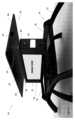
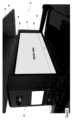
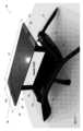
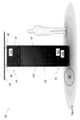
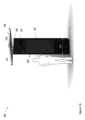
図1-図4は、例示的なVMDU(Vehicle Mounted Display Unit)10を示す図である。VMDU10は、例えば、広告、公共サービスアナウンスなど、公道に沿って公衆に情報を表示するために採用されてもよい。さらに、VMDU10は、任意のサイズ及び形状で製作されてもよく、車両12に直接に又は間接的に取り付けられてもよく、任意の向き(例えば、車両12の長手方向寸法に、平行、角度付き、及び/又はその他の向き)で取り付けられてもよい。さらに、図1-図7のVMDU10は、車両12のルーフ13に取り付けられるものとして示されているが、VMDU10は、車両12の他の部分(例えば、フード(ボンネット)および/またはトランク)に取り付けられてもよい。 1-4 are diagrams illustrating an exemplary vehicle mounted display unit (VMDU) 10. FIG.
車両12は、ガソリン式、ハイブリッド式(例えば、ガソリンおよび電気)、ディーゼル式、電気式、燃料電池式、水素式、人力式、それらの何らかの組み合わせ、などであってもよい。さらに、車両12は、例えば限定されないが、個人用車両、商用車、ライドシェア車両、タクシー、リムジン、タウンカー、バス、SUV、セダン、配送車両、トレーラー、バン、バイク、スクーター、三輪車などを含む任意のタイプの車両であってよい。
図示のように、VMDU10は、取り付けシステム14によって車両12に間接的に取り付けることができる。取り付けシステム14は、1つまたは複数のクロスバー16を含んでいてもよい。クロスバー16は、車両12のルーフ13に固定されるように構成されてもよい。クロスバー16は、任意のサイズ、形状(例えば、断面)およびタイプで作製されてもよい。クロスバー16は、VMDU10をしっかりと支持するために十分な程度の強度及び剛性を提供するように構成されてもよい。 As shown,
取り付けシステム14は、VMDU10をクロスバー16に取り付ける(例えば、VMDUハウジング20をクロスバー16に取り付ける)ための、および/または、クロスバー16を車両12に取り付けるための1つまたは複数のボルト、ネジ、ブラケット、留め具、アダプタ、これらの何らかの組み合わせ等を更に含んでいてもよい。代替的に、又は追加的に、接着剤、溶接、接合、それらの何らかの組み合わせ、又は他の接合技術が利用されてもよい。
サイズおよび形状(例えば、実質的に長方形)が異なってもよい1つ以上の支持体36が提供されてもよい。支持体36は、ハウジング20と1つ以上の太陽エネルギ取得装置24の各々との間に垂直に延びて、太陽エネルギ取得装置24の底面をVMDU10の上面から持ち上げることができる。そうすることで、VMDU10へのアクセスを容易にすることができ、これは、保守及びサービス作業のために有用であり得る。一例では、支持体36は、第1の端部においてハウジング20に取り付けられてもよい。支持体36は、ハウジング20上に配置された吊上げ用アイボルトに取り付けられてもよい。他の例示的な実施形態では、支持体36は、ハウジング20の一部又は全部に又はそれを通して延在してもよく、VMDU10の1つ以上の内部構造構成要素及び/又は取り付けシステム14の1つ以上の構成要素に(例えば、クロスバー16に)取付けられてもよい。例示的な実施形態において、第1の支持体36は、VMDU10の近位部分に配置されてもよく、第2の支持体36は、VMDU10の遠位部分に配置されてもよい。支持体36の他の数量及び配置も利用されてもよい。支持体36および/または本明細書に記載される他の構成要素の取り付けは、締結具(リベットナット、ボルト、ねじ、釘、それらのいくつかの組み合わせなど)、接着剤、溶接、接着、それらのいくつかの組み合わせなどによって行われてもよい。 One or
いくつかの非限定的な例では、VMDU10は、1つ以上のサイドアセンブリ22を含んでいてもよい。各サイドアセンブリ22は、電子ディスプレイ18を構成してもよい。各サイドアセンブリ22は、サイドアセンブリ22及び/又はVMDU10の他の部分の内部に位置する構成要素へのアクセスを容易にするために、外側にスイングするか、さもなければ回転、ピボット、または移動するように構成されてもよく、この構成要素は、標識、冷却経路、照明、ファン、電子ディスプレイ、取り付け構成要素、構造構成要素、電気回路、VMDU10および/または太陽エネルギ取得装置24を操作するための種々の電子機器、それらのいくつかの組み合わせ、又は同様のものを含むことができる。各サイドアセンブリ22は、電子ディスプレイ層、透明カバーパネル、バックライト、これらの何らかの組み合わせ、または同様のものを含んでいてもよい。バックライトは、直接バックライト、エッジ照明、それらの何らかの組み合わせ、又は同様のものから構成されてもよい。他の例示的な実施形態では、電子ディスプレイ18は、有機発光ダイオード型ディスプレイなどの発光型ディスプレイであってよいが、これに限定されないので、別個のバックライトは必要でない場合がある。電子ディスプレイ18は、液晶、有機発光ダイオード、QLED、発光ダイオード、陰極線管、プラズマ、それらのいくつかの組合せなど、これらに限定されない任意のタイプの電子ディスプレイであってよい。 In some non-limiting examples,
例示的な実施形態では、VMDU10の上面と太陽エネルギ取得装置24の下面との間に少なくとも5インチのクリアランスが提供されてもよいが、任意の距離、または様々な距離が利用されてもよい。このクリアランスは、電子ディスプレイ18、VMDU10、車両12の内部、又はそれらのいくつかの組み合わせなどに影を落とすことを容易にし、それによってVMDUが過度の太陽(例えば、熱)負荷を受けることを防止し、および/または、特定の望ましい空力的効果を提供するために提供されてもよい。 In an exemplary embodiment, a clearance of at least 5 inches may be provided between the top surface of
補強材34が設けられてもよい。補強材34は、基板32の下面に沿って水平に延びていてもよい。補強材34は、1つ以上の支持体36のそれぞれのいずれかの側から延在していてもよい。図示の補強材34は、太陽エネルギ取得装置24の幅W2全体にわたって実質的に延在しているが、これは必須ではない。例示的な実施形態において、補強材34は、1つ以上の支持体36の各々の上面と基板32の下面との間に挟まれてもよい。補強材34は、太陽エネルギ取得装置24の一部又は全部の下に設けられてもよく、構造的安定性、強度、及び/又は剛性を提供してもよい。 A
例示的な実施形態では、太陽エネルギ取得装置24は、他の形状も企図されるが、実質的に長方形の形状であってもよい。太陽エネルギ取得装置24は、ハウジング20の幅W1よりも大きい幅W2を有してもよい。代替的に、または追加的に、太陽エネルギ取得装置24は、ハウジング20の長さL1よりも大きい長さL2を有してもよい。幅寸法W1,W2および長さ寸法L1,L2は、それぞれ、太陽エネルギ取得装置24及びハウジング20の最大幅寸法及び最大長寸法であってよい。別の言い方をすれば、太陽エネルギ取得装置24は、ハウジング20のフットプリントよりも大きなフットプリントを有していてもよい。これは、太陽エネルギを収集するための増加した表面積を提供し得る。これは、追加的又は代替的に、屋外環境に置かれたときに、ハウジング20、その様々な構成要素(電子ディスプレイ18など)、および/または車両12の一部又は全部を陰にする可能性がある。そのような遮光は、改善された色飽和度、コントラスト、それらのいくつかの組み合わせなどを含むがこれらに限定されない、より良い画像品質をもたらす可能性がある。これは、電子ディスプレイ18を駆動するために必要な輝度レベルを低下させ、したがって、冷却の必要性を低下させる結果になり得る。影はまた、VMDU10が受ける太陽負荷を減少させ、したがって、冷却の必要性を減少させることができる。 In an exemplary embodiment, solar
当業者は、太陽エネルギ取得装置24の任意のサイズ、形状、数、タイプ、および向きが、本開示の範囲から逸脱することなく利用され得ることを理解するであろう。L1、L2、W1およびW2は最大寸法を表すことができるが、L1、L2、W1および/またはW2の1つ又は複数は最小寸法を表すことができる。例えば、限定されないが、太陽エネルギ取得装置24の最小寸法W2および/またはL2は、ハウジング20の最大寸法W1および/またはL1より大きくてもよい。 Those skilled in the art will appreciate that any size, shape, number, type, and orientation of solar
太陽エネルギ取得装置24は、1つまたは複数の光電池28を含んでいてもよい。光電池28は、1つ以上の基板32に搭載されてもよい。通常、光電池28および/または基板32は、粗いエッジから構成されてもよい。光電池28および/または基板32の外縁の周囲には、サイドエッジ26が設けられていてもよい。サイドエッジ26は、歩行者との関係で、より安全であり、且つより審美的に魅力的である、より滑らかな表面を提供してもよい。 Solar
太陽エネルギ取得装置24には、1つまたは複数のアンテナ30が設けられていてもよい。アンテナ30は、無線信号、セルラー信号、GPSまたは他の位置追跡信号、Bluetoothまたは他の近距離無線通信信号、これらのいくつかの組み合わせなどを受信および/または送信するように、構成されていてもよい。アンテナ(複数可)30は、基板32に取り付けられてもよく、第1のアンテナ30は基板32の前部分に設けられてよく、第2のアンテナ30は基板32の後部分に設けられてよい。これらのアンテナ(複数可)30は、基板32の側縁に対して中央に配置されてもよい。アンテナ30の任意の数及び位置が利用されてもよいが、示されたアンテナ(複数可)30の構成は、障害物を最小化し、それによって信号の送信および/または受信を改善することができる。 The solar
太陽エネルギ取得装置24には、1つ以上のカメラ44が設けられてもよい。カメラ44は、基板32に取り付けられてもよい。例示的な実施形態において、第1および第2のカメラ44は、それぞれ、基板32の左側及び右側に設けられてよく、前方から後方に向かって中央に配置されてよい(ただし、カメラ44の任意の数及び位置が利用されてよい)。他の例示的な実施形態では、カメラ44は、補強材34のうちの1つ以上の遠位端に配置されてもよい。カメラ(単数または複数)44の他の数量および位置も、本開示の範囲から逸脱することなく利用されてもよい。1つの非限定的な実施形態において、カメラ(複数可)44は、画像および/または映像が利害関係者に送信され得るように、アンテナ30と電子通信していてもよい(ただし、そのようにすることは必須ではない)。動作において、これは、様々な異なる目的のうちの1つ以上のために実行されてもよく、例えば、近くの人々の人口統計学に基づいて、どの広告および/または公共サービスアナウンスが適切であり得るかを決定することが挙げられるが、これらに限定されない。さらに、または代替的に、このデータは、電子ディスプレイ18を遠隔でオフにするために使用することもできる。 Solar
太陽エネルギ取得装置24は、電子ディスプレイ18の1つ以上のエネルギ貯蔵装置38など、VMDU10の様々な構成要素と電気的に接続されていてもよいが、これらに限定されるわけではない。加えて、または代替的に、太陽エネルギ取得装置24は、1つ以上のエネルギ源40と電気的に接続されてもよい。エネルギ貯蔵装置38は、1つ以上の電池から構成されてもよい。エネルギ源40は、1つ以上のバッテリ、オルタネータ、これらのいくつかの組み合わせ、またはこれらと同様のものから構成されてもよい。例示的な実施形態では、エネルギ貯蔵装置38とエネルギ源40とは、このようなことは必須ではないが、1つで同じであってもよい。 Solar
コントローラ42は、太陽エネルギ取得装置24、VMDU10、エネルギ貯蔵装置38およびエネルギ源40のうちの1つ又は複数の間に介在してもよい。コントローラ42は、エネルギ貯蔵装置38および/またはエネルギ源40から電力を引き出すタイミング、ならびに太陽エネルギ取得装置24からエネルギ貯蔵装置38に余剰エネルギを供給するタイミングを決定するように、構成されてもよい。
エネルギ貯蔵装置38、エネルギ源40およびコントローラ42などの特定の構成要素は、VMDU10および太陽エネルギ取得装置24の外部に位置するものとして図示されているが、このような構成要素は、部分的又は全体的に、VMDU10および/または太陽エネルギ取得装置24の内部にあってもよい。換言すれば、これらの構成要素は、任意の場所に配置することができる。 Although certain components, such as
VMDU10は、温度センサ、ファン速度センサ、環境光センサ、加速度センサ、これらのいくつかの組み合わせなど、1つ以上のセンサ11を含んでいてもよいが、これらに限定されるものではない。このようにして、冷却の量、電子ディスプレイ18の輝度、ファンの速度、これらのいくつかの組み合わせなどが、周囲温度、車両12の動き、周囲照明条件(影を落とす量を含むが、これに限らない)、これらのいくつかの組み合わせなどに基づいて調整されてもよい。無線接続が利用される場合、データは、これらのセンサ11によって収集されてもよく、この種のデータが望まれる1つ以上の遠隔当事者および/または場所に送信されてもよい。
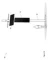
図5乃至図7は、別の例示的なVMDU10を示す図である。VMDU10は、細長い形状を有していてもよく、これは、リムジン、バス、RV車、トレーラーおよび/または同様のものなど、特に長い車両12に適している可能性があるが、これらに限定されるものではない。このような実施形態では、細長い太陽エネルギ取得装置24は、太陽エネルギ取得装置24(これも細長い場合がある)が適切に支持されることを保証するために、複数の支持体36を備えてもよい。他の例示的な実施形態では、複数の太陽エネルギ取得装置24は、VMDU10に沿って実質的に直線的に提供されてもよい。しかしながら、当業者は、電子ディスプレイ18および/または太陽エネルギ取得装置24の任意のサイズ、数および配置が、本開示の範囲から逸脱することなく、任意のサイズおよび型の車両12に利用され得ることを理解するであろう。 5-7 are diagrams illustrating another
VMDU10は、実質的に長方形の形状であってもよいが、他のサイズのVMDU10および/または他の形状のVMDU10も利用することができる。同様に、太陽エネルギ取得装置24は、任意のサイズ、形状、向き(例えば、面一または斜めに取り付けられた)、数、タイプ(例えば、不透明、透明、または半透明のパネル)、組成(例えば、1以上の光起電力セルから成る)および/または同種のもので提供されてもよい。さらに、太陽エネルギ取得装置24の一部または全部は、旋回するように、枢動するように、傾斜するように、回転するように、これらのいくつかの組み合わせ、および/または同種のもので、構成されることさえある。このような動きは、太陽の動きを追跡するように構成されたモータおよびコントローラなど、手動又は自動で達成されてもよい。
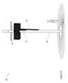
図8は、別の例示的なVMDU10を示す。VMDU10は、太陽エネルギ取得装置(複数可)24とは別個であるが、電気的に接続されているディスプレイユニット29を含んでいてもよい。ディスプレイユニット29は、ハウジング20内に部分的に、または全体的に配置された1つまたは複数の電子ディスプレイ18を含んでいてもよい。ハウジング20は、車両12に取り付けられてもよい。1つ以上の取り付け支持体37は、ハウジング20から、またはハウジング20の内部で、車両12の一部まで延び、それに固定されてもよい。例えば、これに限定するものではないが、ディスプレイユニット29は、車両12の後方部分、側方部分、前方部分、ルーフ、これらのいくつかの組み合わせなどに取り付けられてもよい。ディスプレイユニット29の配置は、視認性を向上させ、複数のディスプレイを提供し、および/または空気力学を向上させるように選択されてもよい。複数のディスプレイユニット29が提供されてもよく、これらの各々は、車両12の異なる部分のうちの同じ部分に取り付けられてもよい。 FIG. 8 shows another
例示的な実施形態では、太陽エネルギ取得装置24の大きさは、約1x2mとすることができるが、太陽エネルギ取得装置24のサイズ、形状および数は、任意で利用されてもよい。太陽エネルギ取得装置24は、車両12の別の場所に取り付けられてもよい。例示的な実施形態では、太陽エネルギ取得装置24は、クロスバー16によってなど、車両12の屋根部分に取り付けられるが、これに限定されず、他の場所および他のタイプの取り付け装置が利用されてもよい。例えば、これに限定されないが、太陽エネルギ取得装置24は、車両12の後方部分、側部、前部、ルーフ、これらのいくつかの組み合わせなどに取り付けられてもよい。太陽エネルギ取得装置24の配置は、太陽光への露出を改善するように、複数のソーラーパネルを提供するように、および/または空気力学を改善するように、選択されてもよい。複数の太陽エネルギ取得装置24が提供されてもよく、これらの各々は、車両12の異なる部分のうちの同じ部分に取り付けられてもよい。 In an exemplary embodiment, the size of solar
太陽エネルギ取得装置24と、電子ディスプレイ18(ただし、これに限定されない)などのディスプレイユニット29の1つ以上の構成要素との間に、配線などによる電気的接続を設けてもよい。このような接続は、クロスバー16、他の取り付け装置、および/または取り付け支持体37の中に部分的に又は完全に、延在していてもよい。1つ以上のエネルギ貯蔵装置38、エネルギ源40および/またはコントローラ42は、太陽エネルギ取得装置24とディスプレイユニット29との間に電気的に介在してもよい。例示的な実施形態では、1つ以上のエネルギ貯蔵装置38、エネルギ源40および/またはコントローラ42は、太陽エネルギ取得装置24および/またはディスプレイユニット29に設けられてもよい。 Electrical connections, such as by wiring, may be provided between the solar
ディスプレイユニット29の各々及び太陽エネルギ取得装置24の各々を含むがこれらに限定されないVMDU10を車両12の様々な部分に固定するために、クロスバー16、取り付け支持体37、支持体36、部材、接着剤、締結具、溶接、結び、これらのいくつかの組み合わせなどの任意の数のタイプの取り付けデバイスを利用することができる。 Cross bars 16, mounting supports 37, supports 36, members, adhesives, etc. are used to secure
図9は、VMDU10の例示的な冷却システムの上面断面図である。VMDU10は、1つ又は複数の冷却経路を含んで構成される。かかる冷却経路は、周囲空気21を1つ以上の開ループ経路19に取り込み、排出するように構成された開口部を含んでいてもよい。例示的な実施形態において、開ループ経路19は、電子ディスプレイ18のためのバックライトに沿って通過してもよい。このような冷却経路は、追加的に又は代替的に、ガス(気体)23を循環させるためにVMDU10内に完全に位置する閉ループ経路17を含んでもよい。例示的な実施形態では、閉ループ経路17は、所定のサイドアセンブリ22の透明カバーパネルと電子ディスプレイ18との間のギャップ(すき間)を通過することによって電子ディスプレイ(単数または複数)18を包囲してもよい。更に、様々な構成要素が、閉ループ経路17および開ループ経路19のいずれか一方内に配置されてもよい。例えば、VMDU10を動作させるための1つ以上の電子部品は、閉ループ経路17内又は閉ループ経路17に沿って提供されてもよい。周囲空気を強制的に通過させるために、1つ又は複数のファンが開ループ経路19内又は開ループ経路19に沿って提供されてもよい。1つ以上のファン27が、閉ループ経路17内に、または閉ループ経路17に沿って設けられ、循環ガスを強制的に通過させることができる。熱交換器25を、好ましくは電子ディスプレイ(単数または複数)18の背後に設けて、閉ループ経路17内の比較的暖かい循環ガス23と開ループ経路19内の比較的冷たい周囲空気21との間の熱伝達を可能にしてもよい。 FIG. 9 is a top cross-sectional view of an exemplary cooling system for
図10は、VMDU10および関連部品を動作させるための例示的なロジックを有するフローチャートを提供する。コントローラ42は、VMDU10を動作させるために必要な電力量を決定してもよい。この決定は、少なくとも部分的に、センサ11からの読み取り値、VMDU10からの動作データ、履歴情報、予測、これらのいくつかの組み合わせなどに基づいて行われてもよい。十分に晴れた条件の間、コントローラ42は、太陽エネルギ取得装置24から収集された電力をVMDU10に向けるように構成されてもよい。余剰エネルギが収集される場合、コントローラ42は、このような余剰電力を1つ以上のエネルギ貯蔵装置38に向けるように構成されてもよい。夜間または曇りの間など、太陽エネルギ取得装置24から十分なエネルギが提供されない場合、コントローラ42は、1つ以上のエネルギ貯蔵装置38および/またはエネルギ源40からVMDU10にエネルギを向けるように構成されてもよい。このようにして、VMDU10は、太陽エネルギ取得装置24によって定期的に、または継続的に電力供給されてもよい。特定の車両12については、これは燃費の改善をもたらす可能性があるが、そのようなことは必須ではない。 FIG. 10 provides a flowchart with example logic for operating VMDU 10 and related components.
コントローラ42は、VMDU10からの電気的引き込みを監視するように構成されてもよい。コントローラ42は、代替的又は追加的に、太陽エネルギ取得装置24からの発電を監視するように構成されてもよい。電気の引き込みおよび生成は、電流、ワット数、電圧、これらの組み合わせ等のうちの1つ以上の形態で監視されてもよい。コントローラ42は、代替的または追加的に、以下のうちの1つまたは複数を監視するように構成されてもよい:周囲照明条件(1つまたは複数の周囲光センサ11による);予測される天候条件(ネットワーク接続デバイス15の方法でアクセスされるネットワークアクセス可能な天候データによる);現在または予測される電気課金レート(ネットワーク接続デバイス15の方法でアクセスされるネットワークアクセス可能なレートデータによる);ユーザ設定(ネットワーク接続デバイス15の方法により受信);および、これらのいくつかの組み合わせまたは同種のもの。このような情報を利用する際に、コントローラ42は、どのエネルギ源(複数可)40から引き出すかを決定するように構成されてもよい。
例示的な実施形態において、電気システムは、完全に直流(「DC」)であってもよい。例えば、これに限定されないが、VMDU10、太陽エネルギ取得装置24、エネルギ貯蔵装置38、エネルギ源40、コントローラ42、これらのいくつかの組み合わせなどは、直流電力のみを使用して動作するように構成されてもよい。本明細書で利用される構成要素及び電力は、これらに限定されない例示的な実施形態において、AC-DC又はDC-ACインバータ等が必要とされないように、直流電力のみを利用することができる。 In an exemplary embodiment, the electrical system may be entirely direct current ("DC"). For example, but not limited to,
図11は、VMDU10及び関連部品を動作させるための例示的なロジックを有するフローチャートを提供する。コントローラ42は、VMDU10を動作させるのに必要な電力量を決定してもよい。この決定は、少なくとも部分的に、センサ11からの読み取り値、VMDU10からの動作データ、履歴情報、予測、これらのいくつかの組み合わせなどに基づいて行われてもよい。十分に晴れた条件の間、コントローラ42は、太陽エネルギ取得装置24から収集された電力をVMDU10に向けるように構成されてもよい。十分なエネルギが収集される場合、コントローラ42は、1つ以上の太陽エネルギ取得装置24によって生成されたエネルギによってのみ、VMDU10に電力を供給するように構成されてもよい。1つ以上の太陽エネルギ取得装置24によって生成された電力が、VMDU10に電力を供給するには不十分である場合、コントローラ42は、1つ以上の太陽エネルギ取得装置24によって供給される電力を1つ以上のエネルギ貯蔵装置38からの電力で補完するように構成されていてもよい。このように、電力は、エネルギ貯蔵装置38および/またはエネルギ源40から引き出されてもよい。電力は、必要なときだけ、また、1つ以上の太陽エネルギ取得装置24によって生成された電力を補完してVMDU10の電力要件を満たすために必要な量だけ、エネルギ貯蔵装置38及び/又はエネルギ源40から引き出されてもよい。このようにして、エネルギ貯蔵装置38および/またはエネルギ源40の負担は、低減又は排除されてもよい。さらに、VMDU10は、太陽エネルギ取得装置24によって定期的に、連続的に、部分的に、または全体的に電力を供給されてもよい。特定の車両12について、これは、他の利点の中で、改善された燃費をもたらすかもしれないが、このようなことは必須ではない。これはまた、VMDU10の環境への影響も低減することができる。 FIG. 11 provides a flowchart with example logic for operating VMDU 10 and related components.
コントローラ42は、VMDU10の電気の引き込みおよび/または必要性を監視するように構成されてもよい。コントローラ42は、代替的又は追加的に、太陽エネルギ取得装置24からの電気生産を監視するように構成されてもよい。電気の引き込み、ニーズおよび/または生産は、電流、ワット数、電圧、これらの組み合わせなどのうちの1つ以上を測定することによって監視されてもよい。コントローラ42は、代替的に又は追加的に、以下のうちの1つ以上を監視するように構成されてもよい:周囲照明条件(1つ以上の周囲光センサ11の方法によって);予測気象条件(ネットワーク接続デバイス15の方法によってアクセスされるネットワークアクセス気象データの方法によって);現在又は予測電気課金レート(ネットワーク接続デバイス15の方法によってアクセスされるネットワークアクセスレートデータの方法によって);ユーザ設定(ネットワーク接続デバイス15の方法で受信);および、これらのいくつかの組み合わせまたは同種のもの。コントローラ42は、どのエネルギ源(複数可)40を利用するかを決定するために、このような情報を利用するように構成されてもよい。
VMDU10の動作は、VMDU10の電力要件を上げるまたは下げるように調整されてもよい。例えば、これに限定されないが、VMDU10の動作に必要な電力が太陽エネルギ取得装置24によって生成される電力よりも小さい場合、画質を改善するためにバックライトレベルを上げる(ただし、これに限定されるものではない)などの特定の動作は、調整されてもよい。別の例として、これに限定されないが、VMDU10の動作に必要な電力が太陽エネルギ取得装置24によって生成された電力よりも所定量だけ大きい場合、太陽エネルギ取得装置24がVMDU10に完全にまたはより完全に電力を供給できるようにバックライトレベルを下げる(ただし、これに限定されるものではない)などの特定の動作は、調整されてもよい。 The operation of
例示的な実施形態において、電気システムは、完全に直流(「DC」)であってもよい。例えば、これに限定されないが、VMDU10、太陽エネルギ取得装置24、エネルギ貯蔵装置38、エネルギ源40、コントローラ42、これらのいくつかの組み合わせ、または同様のものは、DC電力を使用して動作するように構成されてもよい。本明細書で利用される構成要素及び電力は、これに限定されない例示的な実施形態において、AC-DC又はDC-ACインバータ等が必要とされないように、直流電力のみを利用してもよい。 In an exemplary embodiment, the electrical system may be entirely direct current ("DC"). For example, but not limited to, the
図12および図13は、例示的なバスシェルターアセンブリ50を示す図である。バスシェルターアセンブリ50は、バスシェルターアセンブリ50の構造を形成する1つ又は複数の部材56から構成されてもよい。バスシェルターアセンブリ50を歩道、地面、駐車場などに取り付けるための1つ又は複数の脚部51が設けられていてもよい。バスシェルターアセンブリ50の後壁に沿って1つ又は複数のパネル58が配置されてもよい。パネル58は、部材56の少なくとも2つの間に配置されてもよい。パネル58は、不透明な材料、透明な材料、または半透明な材料で構成されてもよい。バスシェルターアセンブリ50の任意の、デザイン、タイプまたはスタイルを利用することができる。 12 and 13 are illustrations of an exemplary
バスシェルターアセンブリ50は、1つ又は複数のディスプレイユニット52を含んでもよい。ディスプレイユニット52は、例えば、広告、公共サービスアナウンスなどを表示するように構成されてもよい。これらのディスプレイユニット52は、本開示の範囲から逸脱することなく、任意の、タイプ、サイズ、向きおよび/または形状のディスプレイを含んでもよい。さらに、これらのディスプレイユニット52は、例えば、バスシェルターアセンブリ50の両側および/または部材56への取り付けなど、バスシェルターアセンブリ50上の任意の適切な位置に取り付けられてもよい。
1つ以上の太陽エネルギ取得装置54は、バスシェルターアセンブリ50の屋根に沿って取り付けられてもよく、または屋根を形成してもよい。屋根の構造を形成する部材56が設けられる場合、太陽エネルギ取得装置54は、当該部材56に取り付けられてもよい。太陽エネルギ取得装置54は、バスシェルターアセンブリ50を使用する個人に対して、日陰、雨および他の天候の保護を提供してもよい。例示的な実施形態において、太陽エネルギ取得装置54は、ディスプレイユニット52に少なくとも部分的な陰を提供するために、ディスプレイユニット52の1つ又は複数の上に延在してもよい。太陽エネルギ取得装置54は、日陰を提供するために採用されてもよいが、太陽エネルギ取得装置54は、不透明であり得る。しかし、他の例示的な実施形態では、太陽エネルギ取得装置54は、透明および/ままたは半透明であってもよい。 One or more solar
様々な屋根部材53は、構造的な支持と剛性を提供するために、太陽エネルギ取得装置54の個々のパネルの間に配置されてもよい。このように、前記屋根部材53は、このような構造の支持および剛性を提供するように、十分な強度、剛性および他の材料特性を有していてもよいことが一般に企図される。1つ以上の例では、屋根部材53は、太陽エネルギ取得装置54を斜めに支持して、太陽エネルギの収集を改善するように構成されてもよい。
太陽エネルギ取得装置54とディスプレイユニット52との間に電気経路102が設けられてもよい。この電気経路102を通じて、太陽エネルギ取得装置54によって生成された電気エネルギは、ディスプレイユニット52にルーティングされ、これに電力を供給してもよい。コントローラ106は、電気経路102に沿って配置され、電気エネルギの流れを、それが必要とされる場所に応じて、方向付けるように構成されてもよい。例えば、コントローラ106は、太陽エネルギ取得装置54、電力網100、これらのいくつかの組み合わせ、および/または同様のものからの電気エネルギを利用するようにディスプレイユニット52を指示するように、構成されてもよい。代替的に、または追加的に、コントローラ106は、ディスプレイユニット52からの電気の引き込みおよび/または太陽エネルギ取得装置54からの電気の生産を監視するように、構成されてもよい。電気の引き込み及び生産は、例えばこれに限定されないが、マイクロワットなどの任意の適切な測定値を用いて監視(例えば定量化)されてもよい。この情報を監視する際に、コントローラ106は、バスシェルターアセンブリ50の1つ又は複数の構成要素に対してどのエネルギ源(複数可)を利用するかを決定するように、構成されてもよい。 An
太陽エネルギ取得装置54によって生成された電力を検出するために、1つまたは複数のセンサ115が利用されてもよい。センサ115からのデータは、動作を制御するためにコントローラ106によって使用されてもよい。電気経路102、コントローラ106およびセンサ115は、ディスプレイユニット52、1つ以上の部材56、太陽エネルギ取得装置54、バスシェルターアセンブリ50の他の構成要素の内部に配置されてもよく、あるいは、バスシェルターアセンブリ50の外部に配置されてもよい。コントローラ106は、ディスプレイユニット52と電力網100と太陽エネルギ取得装置54との間に、介在してもよい。 One or
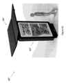
図14乃至図18は、例示的な歩道アセンブリ60を示す。歩道アセンブ60は、歩道、駐車場および/または他の公共の場所など、任意の適切な場所に配置するように構成されてもよく、地面、歩道、駐車場、壁、建物または他の構造物もしくは表面に取り付けられてもよい。各表面設置型アセンブリ60は、1つ以上のディスプレイユニット62、支持部材66および太陽エネルギ取得装置64を含んでもよい。さらに、各ディスプレイユニット62は、1つ以上の電子ディスプレイを含んでもよい。 14-18 illustrate an
1つ以上のディスプレイユニット62を有する歩道アセンブリ60は、任意の適切な配置で、当該ディスプレイユニット62を配置することができる。例えば、これに限定されないが、ディスプレイユニット62のシングル、ダブル、トリプルまたはクワッドのサイドセットが、所定の表面設置型アセンブリ60に提供されてもよい。同様に、各ディスプレイユニット62内の電子ディスプレイも、任意の適切な配置で配置されてもよい。任意の数、サイズ、配置およびタイプの電子ディスプレイが利用されてもよい。さらに、各電子ディスプレイは、三角形または長方形の形状のように互いに物理的に接続され得る、同じまたは別個のディスプレイユニット62内に提供されてもよい。 A
1つ以上の支持部材66は、ディスプレイユニット62の上方で1つ以上の太陽エネルギ取得装置64まで延びていてもよい。実用的には、支持部材66は、太陽エネルギ取得装置64の重量を支持し、このようなものとして、一般に、そのために必要な強度及び剛性を構成することが望ましい。支持部材66は、任意の適切な配置で組み立てられてよく、例えば、支持部材66は、ハウジング67の上面から延びていてもよい。別の例では、支持部材66は、ディスプレイユニット62又は表面設置型アセンブリ60の他の構成要素内に固定されてもよい。 One or
1つ以上の太陽エネルギ取得装置64は、表面設置型アセンブリ60の最大第2寸法D2を超えて延びる、最大第1寸法D1を有してもよい。寸法D1およびD2は、それぞれ、太陽エネルギ取得装置64および表面設置型アセンブリ60の深さであってもよい。代替的に、または追加的に、1つまたは複数の太陽エネルギ取得装置64は、表面設置型アセンブリ60の最大第4寸法D4を超えて延びる、最大第3寸法D3を有してもよい。寸法D3およびD4は、それぞれ、太陽エネルギ取得装置64および表面設置型アセンブリ60の幅であってもよい。別の言い方をすれば、太陽エネルギ取得装置64は、表面設置型アセンブリ60のフットプリントを超えて延びる、フットプリントを有していてもよい。このように、太陽エネルギ取得装置64は、表面設置型アセンブリ60のディスプレイユニット62の一部または全部を陰にすることができる。D1、D2、D3およびD4は、最大寸法を表すことができるが、D1、D2、D3および/またはD4のうちの1つ又は複数は、最小寸法を表すことができる。例えば、これに限定されないが、太陽エネルギ取得装置64の最小寸法D1および/またはD3は、表面設置型アセンブリ60の最大寸法D2およびD4よりも大きくてもよい。例えば、これに限定されないが、太陽エネルギ取得装置64のフットプリントは、ディスプレイアセンブリ60のフットプリントの少なくとも2倍の大きさであってもよい。太陽エネルギ取得装置64は、ディスプレイアセンブリ60の真上に配置されてもよい。太陽エネルギ取得装置64のフットプリントは、ディスプレイアセンブリ60のフットプリントに重なってもよい。 The one or more solar
太陽エネルギ取得装置64は、横方向に延びてもよい。別の言い方をすれば、太陽エネルギ取得装置64は、ディスプレイユニット62の幅に沿って延びてもよい。さらに別の言い方をすれば、太陽エネルギ取得装置64は、前方または後方から見たときに、左から右へまたは右から左へ延びてもよい。代替的に、または追加的に、太陽エネルギ取得装置64は、前方または後方から見たときに、ディスプレイユニット62の意図された視聴者に向かってまたはそこから離れる方向に延びるように配向されてもよい。別の言い方をすれば、太陽エネルギ取得装置64は、前面または背面から見たときに、ディスプレイユニット62の深さに沿って延びてもよい。さらに別の言い方をすると、太陽エネルギ取得装置64は、表面設置型アセンブリ60の前面または背面から見たときに、ページの内にまたはページの外に延びてもよい。 Solar
太陽エネルギ取得装置64は、任意の数だけ、任意の向きで提供されてもよい。例えば、これに限定されないが、太陽エネルギ取得装置64のうちの2つは、互いに平行に延びるように提供されてもよい。別の例として、これに限定されないが、太陽エネルギ取得装置64は、横方向およびディスプレイユニット62の意図された視聴者に向かっておよび視聴者から離れる方向の両方に延びてもよい。さらに別の例として、これに限定されないが、複数の太陽エネルギ取得装置64は、太陽エネルギ取得装置64のいくつかが、表面設置型アセンブリ60のための他の太陽エネルギ取得装置64と比較して異なる方向に延びるように、扇形配列で提供されてもよい。他の方向は、本開示の範囲から逸脱することなく採用することができる。 Solar
例示的な実施形態において、歩道アセンブリ60はそれぞれ、上部部分65、電子ディスプレイ層部分63および下部部分61を含んでもよい。例示的な実施形態では、コントローラ106は、下部部分61に配置されてもよい。他の例示的な実施形態では、コントローラ106は、電子ディスプレイ層部分63、例えば、これに限定されないが、前面向き電子ディスプレイ層と背面向き電子ディスプレイ層との間の密閉されたプレナム内に、配置されてもよい。このような構成要素は、周囲空気からの浸水および/または汚染から保護され得る。さらに別の例では、上部部分65は、無線信号および/または他の信号が上部部分65を出入りすることを可能にするように構成された材料で、構成されてもよい。通信機器は、信号を送受信する能力をさらに高めるために、上部部分65に配置されてもよい。電気経路102は、1つ以上の支持部材66を通って延び、表面設置型アセンブリ60の1つ以上の構成要素を、これらがどの部分61,63,65に位置するかにかかわらず、電気通信状態で配置してもよい。したって、1つ以上の実施例において、支持部材66は、必要な配線を収容するために中空であってもよい。当業者は、このような構成要素のための他の位置及び構成が、本開示の範囲から逸脱することなく利用され得ることを理解するであろう。 In an exemplary embodiment,
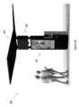
図19乃至図25は、例示的な柱設置型アセンブリ70を示す。柱設置型アセンブリ70は、各々、柱76、1つ以上のディスプレイユニット72および1つ以上の太陽エネルギ取得装置74から構成されてもよい。 19-25 illustrate an exemplary pole-mounted
柱76は、任意の形状からなり、任意の場所に取り付けることができる。例えば、これに限定されないが、柱76は、地面、歩道、建物または他の構造物もしくは表面に取り付けられてもよい。柱76は、円形、三角形、長方形、正方形、六角形、八角形の断面、これらのいくつかの組み合わせ、および/または、このようなものを含んでもよい。柱76は、単に柱設置型アセンブリに適合された、既存の機能を有する、既存の柱から構成されてもよい。柱76は、ライトポール、フラッグポール、サポートポール、円柱、これらのいくつかの組み合わせ、および/または、同様のものから構成されてもよい。 The
柱76には、1つまたは複数のディスプレイユニット72が任意の向きで取り付けられてもよい。例えば、これに限定されないが、1つ、2つ、3つまたは4つのディスプレイユニット72が柱76に取り付けられてもよく、柱76の周りに等間隔に配置されてもよいが、これは必須ではない。これらのディスプレイユニット72は、サイズおよび/または形状(例えば、実質的に立方体の形状および/または丸みを帯びたエッジからなる)が類似しても、異なってもよい。例示的な実施形態では、ディスプレイユニット72は、ディスプレイユニット72のためのハウジングの側面が柱76に取り付けられる旗の向きで柱76に取り付けられてもよい。複数のディスプレイユニット72が取り付けられる場合、かかるディスプレイユニット72は、柱76の対向する側において互いに平行に取り付けられてもよい。また、1つ以上のディスプレイユニット72は、代替的に、または追加的に、ディスプレイユニット72のためのハウジングの後面が柱76に面一に取り付けられてもよい。複数のディスプレイユニット72が柱76に取り付けられる場合、かかるディスプレイユニット72は、柱76の対向する側に、背中合わせに配置されてもよい。フラッシュマウントディスプレイユニット72およびフラッグマウントディスプレイユニット72の組み合わせが、所定の柱76に利用されてもよい。取り付け固定具71は、ディスプレイユニット72の各々から柱76まで延びていてもよい。例示的な実施形態において、取り付け固定具71は、ディスプレイユニット72のためのハウジングに取り付けられてもよい。代替的に、または追加的に、取り付け固定具71は、ディスプレイユニット72の内部構造部品に取り付けられてもよく、ディスプレイユニット72のためのハウジングを貫通して延びてもよい。取り付け固定具71の少なくとも1つの表面は、柱76の形状に実質的に一致するように構成されていてもよい。例えば、これに限定されないが、取り付け固定具71は、ディスプレイユニット72を取り付けるための平坦な外面を有する柱76に取り付けるためのプレートと、湾曲した柱76に取り付けるための湾曲した内面とから構成されてもよい。 One or
取り付け固定具71は、柱76の外周面の一部または全部を包み込むように構成されたカラー77Bを含んでもよい。取り付け固定具71は、代替的に、または追加的に、部材、留め具、ナット、受け具、ボルト、ねじ、釘、接着剤、溶接材、ストラップ、これらのいくつかの組み合わせ等から構成されてもよい。ディスプレイユニット72の柱76への取り付けは、柱76にストラップを巻き付ける、柱76に穴を開ける、ディスプレイユニット72を柱76に締結、ボルト締め、ネジ止め、釘打ち、溶接、接着またはその他の方法で実施してもよい。任意のタイプ、形状、またはサイズの取り付け固定具71を利用することができる。任意のタイプの取り付け技術が利用することができる。 The mounting
ディスプレイユニット72は、1つ以上の周辺装置79を含んで構成されてもよい。このような周辺装置79は、ネットワーク接続装置、電源モジュール、マイクロフォン、カメラ、アンテナ、周囲光センサ、周囲温度センサ、空気品質モニタ、および/または、これららのいくつかの組み合わせを含んでもよいが、これらに限定されるものではない。このような周辺装置79は、ディスプレイユニット72用ハウジングの上面、下面または側面に沿ったドーム、突出部または他の構造で提供されてもよい。
柱76には、1つまたは複数の太陽エネルギ取得装置74が取り付けられてもよい。かかる太陽エネルギ取得装置74は、ディスプレイユニット72の上方に取り付けられてもよいが、かかる太陽エネルギ取得装置74は、任意の場所に取り付けられてもよい。例示的な実施形態において、太陽エネルギ取得装置74は、柱76から斜めに延びていてもよい。太陽エネルギ取得装置74は、地面に対して垂直に延びていてもよい。支持構造78は、柱76の周囲に巻きつく1つ以上のカラー77A,77Bから構成されてもよい。
太陽エネルギ取得装置74は、柱76のディスプレイユニット72と同じ側または異なる側から延在してもよい。太陽エネルギ取得装置74の上端および下端は、ディスプレイユニット72の上端および下端と平行に延びてもよいが、このようなことは必須ではない。太陽エネルギ取得装置74は、柱76上に向けられて、日中の一部又は全部の間、ディスプレイユニット72に陰を落とすように配置されてもよい。 Solar
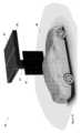
図26乃至図29は、例示的なキャノピー型アセンブリ80を示す。任意のサイズまたはスタイルのキャノピー86を利用することができるが、キャノピー86は、好ましくは、車両88の一部または全部にわたって(例えば、水平に)延びるようなサイズおよび形状であり得る。このように、キャノピー86は、ディスプレイユニットの一部または全てに日陰を提供するとともに、車両88の一部または全てに日陰を提供し、それによって、車両の窓がロールダウンされたときに車両88に雨が侵入することも防止することができる。 26-29 illustrate an
キャノピー型アセンブリ80は、地面からキャノピー86(または後述する太陽エネルギ取得装置84)に沿った位置まで延びる垂直方向に延びる部材81を含んでよく、垂直方向に延びる部材81がキャノピー86および/または太陽エネルギ取得装置84(例えば、キャノピーの周縁ではなく比較的中心付近)のサイズおよび重量を確実に支持することができる。したがって、垂直方向に延びる部材81は、そうするために必要な強度および/または剛性を構成し得ることが一般に企図される。 The canopy-
1つ以上のディスプレイユニット82は、キャノピー型アセンブリ80に取り付けられるか、さもなければ近くに提供されてもよく、サイズ、配置、および構成の点で異なってもよい。例示的な実施形態では、ディスプレイユニット82は、垂直部材81に取り付けられてもよい。ディスプレイユニット82は、デジタルメニューボードを提供するように構成されてもよい。1つ又は複数の太陽エネルギ取得装置84は、キャノピー型アセンブリ80の上部に取り付けられてもよい。かかる太陽エネルギ取得装置84は、キャノピー型アセンブリ80の上面と同一平面上に取り付けられてもよい。このような太陽エネルギ取得装置84は、キャノピー型アセンブリ80の上面に対して斜めに取り付けられてもよい。 One or
太陽エネルギ取得装置(複数可)84は、キャノピー86に対して追加的または代替的に提供されてもよく、透明または半透明であってもよい。追加で提供される場合、太陽エネルギ取得装置(複数可)84は、キャノピー86の上部または他の場所に取り付けられてもよい。太陽エネルギ取得装置84がキャノピー型アセンブリ80の上面と同一平面上にある場合、および/または太陽エネルギ取得装置84がキャノピー型アセンブリ80の上面に対して斜めに取り付けられている場合など、任意の適切な向きが採用されてもよい。他の方向および/または方向の組み合わせも、考えられる。 Solar energy harvesting device(s) 84 may be additionally or alternatively provided to
ディスプレイユニット52,62,72,82の何れもが、片面、両面および/または同様のものであり得る。別の例では、ディスプレイユニット52,62,72,82の各々は、液晶ディスプレイ、プラズマディスプレイ、有機発光ダイオードディスプレイ、発光ダイオードディスプレイ、リアプロジェクションディスプレイ、陰極線ディスプレイ、これらのいくつかの組み合わせ、および/または、同様のもので構成されてもよい。ディスプレイユニット52,62,72,82内の電子ディスプレイ(複数可)は、本開示の範囲から逸脱することなく、任意の数、サイズ、形状、タイプ、向き(例えば、横または縦)、および/または、同様のもので提供されてもよい。さらに、このようなディスプレイユニット52,62,72,82は、直下型バックライト、エッジライト、これらのいくつかの組合せなど、これらに限定されないバックライトを含んでもよい。代替的に、または追加的に、このようなディスプレイユニット52,62,72,82はまた、発光ディスプレイを構成してもよい。構成されるように、前記ディスプレイユニット52,62,72,82は、任意のタイプの情報/画像/映像を表示するようにプログラムされてもよい。さらに別の例では、ディスプレイユニット52,62,72,82の各々は、代替的に、または追加的に、ポスター、アートワーク、看板、変更可能な文字板、これらのいくつかの組み合わせなどの標識を収容するように構成された区画を含み得るポスターホルダを含んでもよい。区画は、ディスプレイユニットハウジング内の透明カバーパネルと電子ディスプレイ(および/またはポスター)との間に規定されてもよい。ポスターホルダは、そこに置かれた看板を照らすための照明装置をさらに含んでもよい。 Any of
ディスプレイユニット52,62,72,82は、実質的に長方形の形状であってもよいが、任意のサイズ及び形状を利用することができる。ディスプレイユニット52,62,72,82は、1つまたは複数の冷却経路を含んでもよい。このような冷却経路は、周囲空気を吸気および排気するように構成された開口部を含んでよく、このような周囲空気を開ループ経路を通して移動させる。例示的な実施形態では、このような開ループ経路は、ディスプレイユニット52,62,72,82のバックライトに沿って延びてもよい。このような冷却経路は、追加的に、または代替的に、ガスを循環させるためにディスプレイユニット52,62,72,82の内部に完全に位置する閉ループ経路を含んでもよい。例示的な実施形態では、閉ループ経路は、透明カバーパネルと電子ディスプレイ表面との間のギャップ(すき間)に循環ガスを通すことによって、ディスプレイユニット52,62,72,82の電子ディスプレイを取り囲んでもよい。ディスプレイユニット52,62,72,82を操作するための1つまたは複数の電子部品が、閉ループ経路内、閉ループ経路沿い、または閉ループ経路に隣接して設けられてもよい。このような電子部品は、周辺装置79、ビデオプレーヤ、電源、コントローラ、ネットワーク接続装置、アンテナ、コンピュータ、これらのいくつかの組合せ、またはこれらと同様のもので構成されてもよい。1つ以上のファンが、開ループ経路内または開ループ経路に沿って設けられ、周囲空気を強制的に通過させることができる。1つ以上のファンが、閉ループ経路内または閉ループ経路に沿って設けられ、循環ガスを強制的に通過させることができる。熱交換器が、好ましくは、ディスプレイユニット52,62,72,82の1つ又は複数の背後に設けられて、閉ループ経路内の比較的暖かい循環ガスと開ループ経路内の比較的冷たい周囲空気との間の熱伝達を可能にしてもよい。
太陽エネルギ取得装置24,54,64,74,84のいずれも、不透明、透明、および/または半透明のパネルを利用してもよく、任意のサイズ、形状、向き(例えば、同一平面または斜めに取り付けられた)、数、タイプ、および/または同様のもので提供されてもよい。これらの太陽エネルギ取得装置24,54,64,74,84は、任意の数の光起電力セルから構成されてもよい。太陽エネルギ取得装置24,54,64,74,84の一部又は全部は、旋回し、枢動し、傾斜し、回転し、これらのいくつかの組み合わせ、または同様のものを行うように、構成されてもよい。このような動きは、太陽の動きを追跡するように構成されたモータおよびコントローラなど、手動または自動で達成されてもよい。 Any of the solar
太陽エネルギ取得装置24,54,64,74,84は、バスシェルターアセンブリ50、表面設置型アセンブリ60、柱設置型アセンブリ70およびキャノピー型アセンブリ80などの様々な構造物に取り付けられる、または他の方法で関連付けられるものとして本明細書に示され又は説明されており、かかる太陽エネルギ取得装置24,54,64,74,84の一部または全ては、代わりに、又は追加として、これに限定されないが、隣接する地面、近くの構造物上(例えば、屋根または柱)、これらのいくつかの組合せまたは同様のものに、配置され得る。これにより、太陽エネルギを効率的に収集するための位置が改善され、ユニットに電力を供給するために拡張された表面積を使用できるようになる。 The solar
図30は、様々なアセンブリ50,60,70,80および関連するコンポーネントを動作させるための例示的な論理を有するフローチャートを提供する。コントローラ106は、アセンブリ50,60,70,80を動作させるために必要な電力量を決定してもよい。この決定は、コントローラ106によって実行されてもよく、少なくとも部分的に、センサ115からの読み取り値、アセンブリ50,60,70,80からの動作データ、履歴情報、予測、これらのいくつかの組み合わせ、または同様のものに基づくことができる。太陽エネルギ取得装置54,64,74,84によって収集される電気エネルギの量が、決定されてもよい。太陽エネルギ取得装置54,64,74,84は、任意の高さが利用され得るが、地表から少なくとも9.5フィート(2.8956メートル)の高さに配置されてもよい。コントローラ106は、収集されたエネルギが必要な電力以上であるか否かを判断するように、構成されてもよい。「はい(yes)」の場合、コントローラ106は、太陽エネルギ取得装置54,64,74,84によって収集された電力のみでアセンブリ50,60,70,80に電力を供給するように構成されてもよい。「いいえ(No)」の場合、コントローラ106は、太陽エネルギ取得装置54,64,74,84からすべての利用可能なエネルギを引き出し、アセンブリ50,60,70,80に電力を供給するのに十分な電力を電力網100から補足的に引き出すように構成されてもよい。 FIG. 30 provides a flowchart with example logic for operating
非限定的な一例では、太陽エネルギ取得装置54,64,74,84によって生成された電力は、条件が十分に晴れたときにディスプレイユニット52,62,72,82に電力を供給するために使用されてもよい。この例では、太陽エネルギ取得装置54,64,74,84によって生成された電力は、アセンブリを動作させるために必要な電力以上であってよい。余剰エネルギがある場合、そのエネルギは、電力網100に送り返されてもよい。 In one non-limiting example, the power generated by the solar
別の非限定的な例では、太陽エネルギ取得装置54,64,74,84によって生成された電力は、ディスプレイユニット52,62,72,82を動作させるのに不十分である場合がある。これは、例えば、太陽エネルギ取得装置が十分な太陽エネルギを受け取っていない場合(例えば、曇りすぎ、太陽光を遮る障害物、太陽エネルギ取得装置上の破片など)に発生する可能性がある。この場合、アセンブリ50,60,70,80は、電力網100からエネルギを引き出すことができるが、好ましくは、太陽エネルギ取得装置54,64,74,84によって生成されるエネルギの不十分な量を補償するために必要な量だけ、エネルギを引き出すことができる。 In another non-limiting example, the power generated by the solar
例えば、これに限定されないが、太陽エネルギ取得装置54,64,74,84によって生成された電力は、条件が十分に晴れたときにディスプレイユニット52,62,72,82に電力を供給するために使用されてもよい。余剰エネルギがあれば、電力網100に送り返すことができるが、このようなことは必須ではない。 For example, but not limited to, the electrical power generated by the solar
太陽エネルギ取得装置54,64,74,84によって収集されたエネルギの使用は、前記アセンブリが電力網100に依存する量を低減することによって、アセンブリ50,60,70,80の環境への影響を低減することができる。このような太陽エネルギ取得装置54,64,74,84の使用は、より環境的に持続可能な代替エネルギ源として機能し得る。ディスプレイユニット52,62,72,82は、太陽エネルギ取得装置54,64,74,84によって定期的に、または継続的に電力を供給されてもよい。代替的に、または追加的に、アセンブリ50,60,70,80は、電力を電力網100に戻すことによって収益を生み出してもよい。 The use of energy collected by solar
エネルギを貯蔵するために、バッテリ、スーパーキャパシタ、ウルトラキャパシタなどのバルクエネルギ貯蔵装置104が一般的に使用される。太陽エネルギ取得装置54,64,74,84は、太陽エネルギ取得装置54,64,74,84が余剰エネルギを発生しているとき(例えば、晴天時など)、バルクエネルギ貯蔵装置104にエネルギを貯蔵してもよい。そして、太陽エネルギ取得装置54,64,74,84によって生成されたエネルギが減少し始めると(例えば、暗いときなど)、バルクエネルギ貯蔵装置104内の貯蔵エネルギは、電力を供給するために使用されてもよい。 Bulk
しかしながら、アセンブリの例示的な実施形態では、バルクエネルギ貯蔵装置104は使用されない。このようなバルクエネルギ貯蔵装置104は、これに限定されないが、例えば、可燃性材料からなる場合があり、希土類材料を必要とする場合があり、アセンブリ内の物理的空間を占有する場合があり、いくつかの例を挙げると、定期的な交換を必要とする場合があるので、不都合なものと考えることができる。本開示のアセンブリ50,60,70,80は、電力網100から補足エネルギを引き出すことができるので、例示的な実施形態は、このようなバルクエネルギ貯蔵装置104を必要としない。 However, in the exemplary embodiment of the assembly, bulk
例示的な実施形態では、AC-DCコンバータは、不要である。例えば、これに限定されないが、ディスプレイユニット52,62,72,82は、AC及びDC両方の電力を直接受け入れるように構成されてもよいが、このようなことは必須ではない。例示的な実施形態では、ディスプレイユニット52,62,72,82は、太陽エネルギ取得装置54,64,74,84によって生成されたDC電力を直接受け入れるように構成されてもよく、ディスプレイユニット52,62,72,82は、電力網100によって生成されたAC電力を直接受け入れるように構成されてもよい。AC電力およびDC電力間を変換するために、必要に応じてインバータが提供され得る。 In an exemplary embodiment, an AC-DC converter is not required. For example, and without limitation,
図31は、アセンブリ60の例示的な実施形態を示す概略図である。アセンブリ60は、2つ以上のソーラーパネルを有するソーラーパネルアレイ64を含んでもよい。アセンブリ20は、2つ以上の電子ディスプレイ49から構成されてもよい。アセンブリ60は、各電子ディスプレイ49のためのDC/DC電源59を含んでもよい。アセンブリ50は、AC/DC電源69を含んでもよい。AC/DC電源69、ソーラーパネルアレイ64およびディスプレイユニット62と電子通信するようにコントローラ106が配置されてもよい。例示的な実施形態におけるAC/DC電源69は、これに限定されないが、電力網100を構成してもよい。動作時、ソーラーパネルアレイは、完全なダイオード(または理想的なダイオード)を介してコントローラ106に電力(例えば、34-50ボルト)を供給してもよい。次に、コントローラ106は、この電力を、別の完全なダイオードを介してAC/DC電源(例えば、33ボルト)に、および/またはディスプレイ内のDC/DC電源(例えば、33-50ボルト)にも向けてもよい。 FIG. 31 is a schematic diagram illustrating an exemplary embodiment of
本明細書では、アセンブリ60およびディスプレイユニット62に関して一定の言及がなされているが、様々なアセンブリ50,60,70,80および関連部品に関して、同じまたは同様の配置を利用することができる。 Although certain references are made herein with respect to
図32は、別の例示的な表面設置型アセンブリ60’を示している。表面設置型アセンブリ60’は、表面設置型アセンブリ60と同様であってもよく、および/または、表面設置型アセンブリ60と同じ構成要素の一部又は全部を含んでもよい。表面設置型アセンブリ60’は、1つまたは複数の太陽エネルギ取得装置64’を含んでもよい。複数の太陽エネルギ取得装置64’は、本明細書において以前に示されおよび/または説明された複数の太陽エネルギ取得装置64と同じまたは類似であり得る。例示的な実施形態では、複数の太陽エネルギ取得装置64’は、これに限定されないが、「V」字型を形成するような、互いに斜めに取り付けられた複数のソーラーパネルから構成されてもよい。表面設置型アセンブリ60’は、上部部分65’を含んでもよく、上部部分65と同じまたは類似してもよいが、このようなことは必須ではない。表面設置型アセンブリ60’は、ディスプレイ層部分63’を含んでもよく、これは、ディスプレイ層部分63と同一または類似してもよいが、このようなことは必須ではない。 FIG. 32 shows another exemplary surface mount assembly 60'. Surface-mounted assembly 60' may be similar to surface-mounted
図33は、別の例示的な表面設置型アセンブリ60’’を示している。表面設置型アセンブリ60’は、表面設置型アセンブリ60及び/又は60’と類似してもよく、および/または、表面設置型アセンブリ60及び/又は60’と同じ構成要素の一部又は全部を含んでもよい。表面設置型アセンブリ60’’は、1つ以上の太陽エネルギ取得装置64’’を含んでもよい。太陽エネルギ取得装置64’’は、本明細書において以前に示されおよび/または説明された太陽エネルギ取得装置64及び/又は64’と同一又は類似であってよい。例示的な実施形態では、太陽エネルギ取得装置64’’は、これに限定されないが、「V」字型を形成するような、互いに斜めに取り付けられた複数のソーラーパネルから構成されてもよい。表面設置型アセンブリ60’’は、ディスプレイ層部分63’’を含んでいてもよく、これはディスプレイ層部分63と同じか類似してもよいが、このようなことは必須ではない。 FIG. 33 illustrates another exemplary surface mount assembly 60''. Surface-mounted assembly 60' may be similar to surface-mounted
図34は、例示的な電気回路図である。太陽エネルギ取得装置64は、コントローラ106と電気的に接続された状態で配置されてもよい。コントローラ106は、AC入力110によって、例えば、これに限定されないが、商用電源100と電気的に接続されてもよい。インバータ108は、AC入力110とAC出力112との間に電気的に介在し、必要に応じてAC電力をDC電力に変換してもよい。コントローラ106は、余剰エネルギを貯蔵し、コントローラ106の指示に応じてかかる余剰エネルギを払い出すための1つ以上のエネルギ貯蔵装置104に電気的に接続されてもよい。エネルギ貯蔵装置104は、DC出力114と電気的に接続されてもよい。 FIG. 34 is an exemplary electrical circuit diagram. Solar
DC出力114は、1つ以上のディスプレイユニット62と電気的に接続された状態に置かれてもよい。DC電力は、DC/DC電源59で受け取ることができる。DC/DC電源59は、DC電力を、ディスプレイユニット62、ディスプレイ層部分63のバックライト57および/または様々な電気部品55に、ならびに/または、これらに限定されない、センサ、ファン、冷却装置、顧客装置、電子機器、これらの任意の組み合わせなどの、アセンブリ60の他の様々な部品に、分配することができる。 DC output 114 may be placed in electrical connection with one or
本明細書では、アセンブリ60およびディスプレイユニット62に関して特定の言及がなされているが、様々なアセンブリ50,60,60’,60’’,70,80および関連部品に関して、同じまたは同様の配置を利用することができる。 Although specific reference is made herein to
DC/DCシステムを利用することによって実現される効率の改善を示すために、非限定的な例として、例示的な電気効率を図34に示す。このような効率は、所与の場所に対する過去の天候および他の環境考察に基づくシミュレーションされた天候条件に基づくことができる。 As a non-limiting example, exemplary electrical efficiencies are shown in FIG. 34 to illustrate the efficiency improvements achieved by utilizing a DC/DC system. Such efficiency may be based on simulated weather conditions based on historical weather and other environmental considerations for a given location.
図35は、別の例示的な電気回路図である。太陽エネルギ取得装置64は、コントローラ106と電気的に接続された状態で配置されてもよい。コントローラ106は、これに限定されないが、例えば、AC/DC電源69によって、商用電源100と電気的に接続されてもよい。AC/DC電源69は、例示的な実施形態では、商用電源100からのACエネルギを必要に応じてDC電力に変換するための1つまたは複数のインバータ108を含んでもよい。コントローラ106は、DC/DC電源59に電気的に接続されてもよい。DC/DC電源59は、ディスプレイ層部分63のバックライト57および/または様々な電気部品55に、ならびに、これらに限定されないが、ディスプレイユニット62、センサ、ファン、冷却装置、顧客装置、電子機器、これらの任意の組み合わせなどの、アセンブリ60の他の様々な部品にDC電力を分配してよい。 FIG. 35 is another exemplary electrical circuit diagram. Solar
本明細書では、アセンブリ60およびディスプレイ層部分63に関して特定の言及がなされているが、様々なアセンブリ50,60,60’,60’’,70,80および関連部品に関して、同じまたは同様の配置を利用することができる。 Although specific references are made herein to
DC/DCシステムを利用することによって実現される効率の改善を示すために、非限定的な例として、例示的な電気効率を図35に示す。このような効率は、所与の場所に対する過去の天候および他の環境考察に基づくシミュレーションされた天候条件に基づくことができる。 As a non-limiting example, exemplary electrical efficiencies are shown in FIG. 35 to illustrate the efficiency improvements achieved by utilizing a DC/DC system. Such efficiency may be based on simulated weather conditions based on historical weather and other environmental considerations for a given location.
本発明の任意の実施形態は、本発明の他の実施形態の特徴のいずれかを含むことができる。本明細書に開示された例示的な実施形態は、網羅的であることや本発明の範囲を不必要に制限することを意図していない。例示的な実施形態は、当業者が本発明を実施できるように、本発明の原理を説明するために選択され、説明されたものである。本発明の例示的な実施形態を示し、説明したが、当業者は、説明した本発明に対して多くの変形および修正を実施できることを理解するであろう。これらの変形および修正の多くは、同じ結果を提供し、特許請求の範囲に記載される発明の精神の範囲内に入るものである。したがって、特許請求の範囲によって示されるようにのみ本発明を限定することが意図される。 Any embodiment of the invention may include any of the features of other embodiments of the invention. The exemplary embodiments disclosed herein are not intended to be exhaustive or to unnecessarily limit the scope of the invention. The exemplary embodiments were chosen and described to explain the principles of the invention to enable any person skilled in the art to practice the invention. While exemplary embodiments of the invention have been shown and described, those skilled in the art will recognize that many variations and modifications may be made to the invention as described. Many of these variations and modifications provide the same results and are within the spirit of the claimed invention. It is the intention, therefore, to limit the invention only as indicated by the scope of the claims that follow.
本明細書に記載された特定の動作は、1つまたは複数の電子デバイスによって実施し得る。各電子デバイスは、本明細書に記載された動作を実行するように構成された1つまたは複数のプロセッサ、電子記憶装置、実行可能なソフトウェア命令などを含んでもよい。電子デバイスは、汎用コンピュータであってもよく、特殊なコンピューティングデバイスであってもよい。電子デバイスは、パーソナルコンピュータ、スマートフォン、タブレット、データベース、サーバなどであってもよい。本明細書に記載される電子接続は、有線手段または無線手段によって実現されてもよい。 Certain operations described herein may be performed by one or more electronic devices. Each electronic device may include one or more processors, electronic storage, executable software instructions, etc. configured to perform the operations described herein. The electronic device may be a general purpose computer or a specialized computing device. The electronic device may be a personal computer, smart phone, tablet, database, server, etc. The electronic connections described herein may be realized by wired or wireless means.
Claims (8)
Translated fromJapanese前記電子ディスプレイ用のハウジングであって、車両のルーフへの取付用に構成される前記ハウジングと、
前記ハウジングの上に配置され、前記ハウジングから離れて配置される太陽エネルギ取得装置であって、前記太陽エネルギ取得装置が、前記電子ディスプレイに電気的に接続され、前記太陽エネルギ取得装置が、長方形の形状の基板と、前記基板の上に配置された複数の太陽電池と、を備え、前記太陽エネルギ取得装置は、前記複数の太陽電池が上方を向くように、前記車両の前記ルーフに沿って長手方向に延びる、前記太陽エネルギ取得装置と、
互いに間隔が置かれた第1および第2の支持部材であって、前記第1および前記第2の支持部材の各々が、前記ハウジングの上面と前記太陽エネルギ取得装置の下面との間に延び、前記太陽エネルギ取得装置を前記ハウジングの上方の高い位置で前記ハウジングから間隔を置いて支持する前記第1および前記第2の支持部材と、
前記太陽エネルギ取得装置と、車載バッテリを含む代替電源と、の間に電気的に挿入されたコントローラであって、前記コントローラは、該ディスプレイアセンブリの電力要件と前記太陽エネルギ取得装置による発電とを監視し、前記太陽エネルギ取得装置による前記発電が、該ディスプレイアセンブリの前記電力要件を下回る場合、前記代替電源から電力を供給するように、構成される、前記コントローラと、
を備え、
前記ハウジングが第1の占有面積を規定し、前記太陽エネルギ取得装置が第2の占有面積を規定し、前記第2の占有面積が前記第1の占有面積より大きく、
前記太陽エネルギ取得装置は、前記第2の占有面積が前記第1の占有面積を完全に覆うように、前記ハウジングの真上に配置され、前記太陽エネルギ取得装置の外周は、前記ハウジングの外周を越えて横方向に延びる、
ソーラーパワー式の車両用のディスプレイアセンブリ。electronic display;
a housing for the electronic display, the housing configured for mounting on the roof of a vehicle ;
a solar energy capture device disposed on the housing and spaced apart from the housing,the solar energy capture device being electrically connected to the electronic display, and the solar energy capture device having a rectangular shape. a shaped substrate; and a plurality of solar cells disposed on the substrate, the solar energy acquisition device longitudinally extending along the roof of the vehicle such that the plurality of solar cells face upward. the solar energy harvesting deviceextendingin the direction ;
first and second spaced support members, each of the first and second support members extending betweena top surface of the housing anda bottom surface of the solar energy harvesting device; the firstand second support members supporting the solar energy harvesting device at an elevated location above the housing andspaced from the housing ;
a controller electrically interposed between the solar energy harvesting device and an alternative power source including an onboard battery, the controller monitoring power requirements of the display assembly and power generation by the solar energy harvesting device; and the controller is configured to provide power from the alternative power source if the power generation by the solar energy harvesting device is less than the power requirement of the display assembly;
Equipped with
the housing defines a first footprint, the solar energy harvesting device defines a second footprint, the second footprint isgreater than the first footprint;
The solar energy acquisition device is disposed directly above the housing such that the second occupied area completely covers the first occupied area, and the outer periphery of the solar energy acquisition device overlaps the outer periphery of the housing. extending laterally beyond
Display assemblyfor solar powered vehicles .
前記電子ディスプレイは、前記直流電力を用いて動作するように構成される、
請求項1に記載のソーラーパワー式のディスプレイアセンブリ。The solar energy harvesting device is configured to provide direct current (DC) power;
the electronic display is configured to operate using the direct current power;
The solar powered display assembly of claim1 .
請求項1または2に記載のソーラーパワー式のディスプレイアセンブリ。the alternative power source is configured to provide direct current (DC) power;
A solar powered display assembly according to claim1 or2 .
請求項1乃至3のいずれか1項に記載のソーラーパワー式のディスプレイアセンブリ。the controller is configured to supply any power generated by the solar energy harvesting device to the alternative power source in excess of the power required for the display assembly;
A solar powered display assembly according toanypreceding claim.
更に備え、
前記代替電源は、交流(AC)電力を供給するように構成されており、前記代替電源は、電力網を含む、
請求項1または2に記載のソーラーパワー式のディスプレイアセンブリ。further comprising a converter electrically inserted between the alternative power source and the electronic display;
the alternative power source is configured to provide alternating current (AC) power, and the alternative power source includes a power grid;
A solar powered display assembly according to claim1 or2 .
前記ハウジング内に配置されて、動作時に前記電子ディスプレイを冷却するための1つ以上のファンと、
を更に備え、
前記1つ以上のファンの各々は、前記コントローラに電気的に接続され、直流(DC)電力を使用して動作するように構成される、
請求項1乃至5のいずれか1項に記載のソーラーパワー式のディスプレイアセンブリ。an open loop path for ambient air within the housing;
one or more fans disposed within the housing to cool the electronic display during operation;
further comprising;
each of the one or more fans is electrically connected to the controller and configured to operate using direct current (DC) power;
A solar powered display assembly according toanypreceding claim.
熱交換器と、
を更に備え、
前記開ループ経路が前記熱交換器の第1の部分を含み、
前記閉ループ経路が前記熱交換器の第2の部分を含む、
請求項6に記載のソーラーパワー式のディスプレイアセンブリ。a closed loop path for circulating gas within the housing;
a heat exchanger;
further comprising;
the open loop path includes a first portion of the heat exchanger;
the closed loop path includes a second portion of the heat exchanger;
7. The solar powered display assembly of claim6 .
前記電子ディスプレイは、直下型バックライトを含む、
請求項1乃至7のいずれか1項に記載のソーラーパワー式のディスプレイアセンブリ。The electronic display includes a layer of liquid crystal;
The electronic display includes a direct backlight.
A solar powered display assembly according to anypreceding claim.
Applications Claiming Priority (7)
| Application Number | Priority Date | Filing Date | Title |
|---|---|---|---|
| US201962892104P | 2019-08-27 | 2019-08-27 | |
| US62/892,104 | 2019-08-27 | ||
| US201962911806P | 2019-10-07 | 2019-10-07 | |
| US62/911,806 | 2019-10-07 | ||
| US16/915,774 | 2020-06-29 | ||
| US16/915,774US11285895B2 (en) | 2019-08-27 | 2020-06-29 | Solar powered vehicle mounted display |
| PCT/US2020/047747WO2021041381A1 (en) | 2019-08-27 | 2020-08-25 | Solar powered display assemblies |
Publications (2)
| Publication Number | Publication Date |
|---|---|
| JP2022546393A JP2022546393A (en) | 2022-11-04 |
| JP7395715B2true JP7395715B2 (en) | 2023-12-11 |
Family
ID=74680242
Family Applications (1)
| Application Number | Title | Priority Date | Filing Date |
|---|---|---|---|
| JP2022513050AActiveJP7395715B2 (en) | 2019-08-27 | 2020-08-25 | solar powered display assembly |
Country Status (7)
| Country | Link |
|---|---|
| US (7) | US11285895B2 (en) |
| EP (1) | EP4022595B1 (en) |
| JP (1) | JP7395715B2 (en) |
| KR (1) | KR20220052356A (en) |
| AU (2) | AU2020336047A1 (en) |
| CA (1) | CA3150770A1 (en) |
| WO (1) | WO2021041381A1 (en) |
Cited By (6)
| Publication number | Priority date | Publication date | Assignee | Title |
|---|---|---|---|---|
| USD1029940S1 (en) | 2022-08-31 | 2024-06-04 | Manufacturing Resources International, Inc. | Electronic display unit |
| USD1046762S1 (en) | 2019-10-29 | 2024-10-15 | Manufacturing Resources International, Inc. | Solar powered electronic display assembly with pole mount |
| USD1062872S1 (en) | 2023-03-02 | 2025-02-18 | Manufacturing Resources International, Inc. | Electronic display unit |
| USD1066280S1 (en) | 2024-09-12 | 2025-03-11 | Manufacturing Resources International, Inc. | Electronic display assembly |
| US12250781B2 (en) | 2022-08-31 | 2025-03-11 | Manufacturing Resources International, Inc. | Display assembly with unobstructed zone |
| USD1076846S1 (en) | 2024-09-12 | 2025-05-27 | Manufacturing Resources International, Inc. | Electronic display assembly |
Families Citing this family (23)
| Publication number | Priority date | Publication date | Assignee | Title |
|---|---|---|---|---|
| AU2018237580B2 (en) | 2017-03-24 | 2020-10-15 | Manufacturing Resources International, Inc. | Roof mounting apparatus and system for vehicle topper |
| US11285895B2 (en) | 2019-08-27 | 2022-03-29 | Manufacturing Resources International, Inc. | Solar powered vehicle mounted display |
| US11496091B2 (en) | 2019-08-27 | 2022-11-08 | Manufacturing Resources International, Inc. | Electronic display assemblies with solar panels |
| USD1010858S1 (en) | 2019-10-29 | 2024-01-09 | Manufacturing Resources International, Inc. | Bus shelter with solar powered electronic displays |
| USD957317S1 (en) | 2019-10-29 | 2022-07-12 | Manufacturing Resources International, Inc. | Solar powered electronic display kiosk |
| USD934159S1 (en) | 2019-10-29 | 2021-10-26 | Manufacturing Resources International, Inc. | Canopy with solar powered electronic menu board |
| US11778757B2 (en) | 2020-10-23 | 2023-10-03 | Manufacturing Resources International, Inc. | Display assemblies incorporating electric vehicle charging equipment |
| USD1063105S1 (en)* | 2021-04-26 | 2025-02-18 | Hyundai Motor Company | Canopy for electric vehicle charging stations |
| USD993906S1 (en) | 2021-06-04 | 2023-08-01 | Manufacturing Resources International, Inc. | Combined solar powered electronic display assembly with charging station |
| USD964920S1 (en) | 2021-06-04 | 2022-09-27 | Manufacturing Resources International, Inc. | Solar powered electronic display assembly |
| US11919393B2 (en) | 2021-08-23 | 2024-03-05 | Manufacturing Resources International, Inc. | Display assemblies inducing relatively turbulent flow and integrating electric vehicle charging equipment |
| GB2614748B (en)* | 2022-01-18 | 2024-10-09 | Amscreen Group Ltd | Cooling of electronic displays |
| GB2619746B (en)* | 2022-06-15 | 2025-04-16 | Externiture Ltd | Wayside shelter |
| CN115285035A (en)* | 2022-06-30 | 2022-11-04 | 深圳市有方科技股份有限公司 | Vehicle-mounted terminal and vehicle insurance terminal system |
| US12072561B2 (en) | 2022-07-22 | 2024-08-27 | Manufacturing Resources International, Inc. | Self-contained electronic display assembly, mounting structure and methods for the same |
| US20240067012A1 (en)* | 2022-08-26 | 2024-02-29 | Meridian Kiosks | Electric vehicle charger with optional and configurable digital signage |
| US12039894B2 (en) | 2022-08-31 | 2024-07-16 | Manufacturing Resources International, Inc. | Display assembly with unobstructed zone |
| US12106687B2 (en) | 2022-08-31 | 2024-10-01 | Manufacturing Resources International, Inc. | Display assembly with unobstructed zone |
| DE102022128944A1 (en)* | 2022-11-02 | 2024-05-02 | Audi Aktiengesellschaft | Motor vehicle |
| USD1029778S1 (en) | 2023-06-02 | 2024-06-04 | Manufacturing Resources International, Inc. | Electronic display assembly structure |
| USD1030691S1 (en) | 2023-06-02 | 2024-06-11 | Manufacturing Resources International, Inc. | Electronic display assembly structure |
| USD1070843S1 (en) | 2023-07-17 | 2025-04-15 | Manufacturing Resources International, Inc. | Electronic display assembly |
| JP2025075626A (en)* | 2023-10-31 | 2025-05-15 | 株式会社ヒット | Container Equipment |
Citations (5)
| Publication number | Priority date | Publication date | Assignee | Title |
|---|---|---|---|---|
| JP2012016086A (en) | 2010-06-29 | 2012-01-19 | Sanyo Electric Co Ltd | Outdoor display system |
| US20120224116A1 (en) | 2011-02-03 | 2012-09-06 | Barnes Michael S | Menu display cabinet |
| JP2012255848A (en) | 2011-06-07 | 2012-12-27 | Sanyo Electric Co Ltd | Display system |
| US20150381922A1 (en) | 2014-06-26 | 2015-12-31 | Carl Heath Hamilton | Vehicle-mountable data display device |
| US20160041423A1 (en) | 2008-03-03 | 2016-02-11 | Manufacturing Resources International, Inc. | Heat Exchanger for Back to Back Electronic Displays |
Family Cites Families (184)
| Publication number | Priority date | Publication date | Assignee | Title |
|---|---|---|---|---|
| CA183485A (en) | 1917-01-25 | 1918-04-09 | Utley Wedge | Metallurgical furnace |
| CA183486A (en) | 1917-04-02 | 1918-04-09 | John S. Wertin | Clutch for shafts |
| CA183487A (en) | 1917-04-30 | 1918-04-09 | William Wilkie | Edging machine for garments |
| US3141588A (en) | 1962-05-29 | 1964-07-21 | Karpak Company | Car-top luggage carrier with clamping, support brackets |
| US3525461A (en) | 1968-05-27 | 1970-08-25 | Joseph Bronson | Car top carrier structure with locking means |
| US4534496A (en) | 1974-07-08 | 1985-08-13 | Bott John Anthony | Luggage carrier with illuminating means |
| US3978599A (en) | 1974-12-27 | 1976-09-07 | Thomson-Leeds, Company, Inc. | Illuminated display device |
| US4052806A (en) | 1976-01-12 | 1977-10-11 | Vango Media, Inc. | Display device with adjustable attachment means |
| US4114789A (en) | 1977-04-14 | 1978-09-19 | Lectric Lites Company | Mounting apparatus for vehicle emergency warning signal |
| US4261496A (en) | 1979-09-14 | 1981-04-14 | Four Star Corporation | Ski rack |
| SE436633B (en) | 1982-04-21 | 1985-01-14 | Thule Ind Ab | LOAD SHARE FOR VEHICLES |
| US4500020A (en) | 1982-05-06 | 1985-02-19 | Masco Corp. | Article carrier with adjustably positionable bracket |
| AU574669B2 (en) | 1983-03-29 | 1988-07-14 | Unistrut Australia Pty Limited | Vehicle roof rack |
| DE3418770A1 (en) | 1984-05-19 | 1985-11-21 | Adam Opel AG, 6090 Rüsselsheim | ROOF CARRIER FOR MOTOR VEHICLES |
| US4671004A (en) | 1985-04-06 | 1987-06-09 | Berg Marlin C | Vehicle mounted portable sign |
| US4667428A (en) | 1985-04-29 | 1987-05-26 | Elmer William A | Triangular car top sign |
| AU94645S (en) | 1985-07-10 | 1987-01-08 | Rola Roof Racks Australia Pty Ltd | Roof rack |
| USD296087S (en) | 1986-04-16 | 1988-06-07 | Luck Wallace R | Distress warning signal mountable on the top of an automobile |
| US4768691A (en) | 1986-09-22 | 1988-09-06 | Huron/St. Clair Company, A Division Of Masco Industries, Inc. | Adjustable support rail for a luggage carrier |
| SE8605527L (en) | 1986-12-22 | 1988-06-23 | Thule Ind Ab | LOADER DEVICE |
| SE455589B (en) | 1987-01-12 | 1988-07-25 | Thule Ind Ab | LOADING MOVEMENT FOR A VEHICLE RELEASED FOR A VEHICLE ROOF |
| USD306990S (en) | 1987-03-19 | 1990-04-03 | Bott John A | Vehicle luggage carrier |
| SE459569B (en) | 1987-11-24 | 1989-07-17 | Thule Ind Ab | DEVICE FOR CREATING A LOAD |
| USD314983S (en) | 1988-04-04 | 1991-02-26 | Joe Cangianni | Emergency sign |
| US4972983A (en) | 1988-09-20 | 1990-11-27 | Bott John Anthony | Article carrier |
| US5207365A (en) | 1988-09-20 | 1993-05-04 | Bott John Anthony | Article carrier |
| US4982886A (en) | 1989-03-27 | 1991-01-08 | John A. Bott | Article carrier |
| USD320971S (en) | 1989-08-01 | 1991-10-22 | Huron/St. Clair Incorporated | Article carrier for a passenger vehicle |
| USD326282S (en) | 1989-12-28 | 1992-05-19 | Warrec Company | Vehicle message display sign |
| US5016798A (en) | 1990-04-05 | 1991-05-21 | Huron/St. Clair Incorporated | Spacer insert for load-bearing slats |
| DE4028433C1 (en) | 1990-09-07 | 1992-02-13 | Gebr. Happich Gmbh, 5600 Wuppertal, De | |
| US5132666A (en) | 1990-09-17 | 1992-07-21 | Travel-Ad, Inc. | Vehicle-mounted electronic display system |
| US5170920A (en) | 1991-02-15 | 1992-12-15 | Masco Corporation | Luggage rack |
| US5347736A (en) | 1991-03-15 | 1994-09-20 | Sign-Rite Inc. | Illuminated sign |
| US5171083A (en) | 1991-09-10 | 1992-12-15 | Ltc Roll & Engineering Co. | Combined luggage rack and concealed lights for vehicle roof |
| US5257710A (en) | 1991-09-17 | 1993-11-02 | Fetovu Proprietary Limited | Vehicle roof rack |
| SE469423B (en) | 1991-11-18 | 1993-07-05 | Thule Ind Ab | LASTBAERARE |
| US5306156A (en) | 1992-04-03 | 1994-04-26 | Sport Rack Systems, Inc. | Mechanical and/or electro-mechanical interconnect system for vehicle load carrying components/accessories |
| SE501016C2 (en) | 1993-05-28 | 1994-10-17 | Thule Ind Ab | The load carrier foot |
| US5918397A (en) | 1993-06-14 | 1999-07-06 | Elmer; William A. | Illuminated magnetic advertising sign |
| US5711100A (en) | 1993-06-14 | 1998-01-27 | Elmer; William A. | Vehicle advertising sign, system and method |
| US5385285A (en) | 1993-12-07 | 1995-01-31 | Jac Products, Inc. | Vehicle article carrier |
| US5474218A (en) | 1994-07-25 | 1995-12-12 | Chrysler Corporation | Article carrier |
| JPH08216779A (en) | 1995-02-10 | 1996-08-27 | Yukio Kato | Roof carrier with stop lamp |
| US5845828A (en) | 1996-01-12 | 1998-12-08 | Yakima Products | Tower assembly for mounting a crossbar to a vehicle roof rack |
| USD403434S (en) | 1996-10-22 | 1998-12-29 | Krone Aktiengesellschaft | Bus shelter |
| US5826766A (en) | 1997-03-14 | 1998-10-27 | Jac Products, Inc. | Vehicle article carrier |
| USD398409S (en) | 1997-03-19 | 1998-09-15 | Anis Jessa | Illuminated cab sign |
| CA2233930C (en) | 1997-04-03 | 2006-06-06 | Decoma International Inc. | Article carrier assembly having a cross rail assembly adjustable within a range of infinite operating positions |
| AU136023S (en) | 1997-04-17 | 1998-12-15 | Clear Channel Outdoor Ltd | A set of street furniture |
| DE19716047C2 (en) | 1997-04-17 | 1999-11-25 | Porsche Ag | Fastening device for roof rack |
| SE510962C2 (en) | 1997-11-18 | 1999-07-12 | Thule Ind Ab | Fastener for foot carrier |
| US6114954A (en) | 1998-04-01 | 2000-09-05 | Palett; Anthony P. | Luggage carrier with illumination means |
| DE19929909A1 (en) | 1999-06-29 | 2001-01-04 | Am3 Automotive Multimedia Ag | Attachment with integrated antenna assembly |
| DE19948476C1 (en) | 1999-10-08 | 2001-03-01 | Jac Products Deutschland Gmbh | Automobile roof rail has gallery rail provided at either end with plug-in rail foot provided by high pressure deformation of tubular section of same metallic material as gallery rail |
| USD430901S (en) | 1999-11-22 | 2000-09-12 | Palmer Promotional Products | Two-sided light box |
| US6701143B1 (en) | 1999-12-15 | 2004-03-02 | Vert, Inc. | Apparatus, methods, and computer programs for displaying information on mobile signs |
| US6812851B1 (en) | 1999-12-15 | 2004-11-02 | Vert, Inc. | Apparatuses for displaying information on vehicles |
| US20010030214A1 (en) | 2000-01-07 | 2001-10-18 | Harris Kevin W. | Short roof-line connective adaptation for a cargo carrier |
| US20020164962A1 (en) | 2000-07-18 | 2002-11-07 | Mankins Matt W. D. | Apparatuses, methods, and computer programs for displaying information on mobile units, with reporting by, and control of, such units |
| US6850209B2 (en) | 2000-12-29 | 2005-02-01 | Vert, Inc. | Apparatuses, methods, and computer programs for displaying information on vehicles |
| US20020009978A1 (en) | 2000-07-18 | 2002-01-24 | Semyon Dukach | Units for displaying information on vehicles |
| US20020112026A1 (en) | 2000-07-18 | 2002-08-15 | Leonid Fridman | Apparatuses, methods, and computer programs for displaying information on signs |
| US20020065046A1 (en) | 2000-07-18 | 2002-05-30 | Vert, Inc. | Apparatuses, methods, and computer programs for showing information on a vehicle having multiple displays |
| US6415970B1 (en) | 2000-10-20 | 2002-07-09 | Jac Products, Inc. | Vehicle article carrier with supports configurable elevated siderails or flush mounted slats |
| US20040036622A1 (en) | 2000-12-15 | 2004-02-26 | Semyon Dukach | Apparatuses, methods, and computer programs for displaying information on signs |
| USD453194S1 (en) | 2000-12-15 | 2002-01-29 | Daimlerchrysler Corporation | Pylon sign |
| AU2002251807A1 (en) | 2001-01-23 | 2002-08-19 | Donnelly Corporation | Improved vehicular lighting system for a mirror assembly |
| US7054596B2 (en) | 2001-12-21 | 2006-05-30 | Daimlerchrysler Corporation | Wireless vibration diagnostic instrument |
| SE521631C2 (en) | 2002-04-04 | 2003-11-18 | Thule Sweden Ab | The load carrier foot |
| US20040004827A1 (en) | 2002-07-08 | 2004-01-08 | Guest Christopher William | Light devices using light emitting diodes |
| KR100490371B1 (en) | 2002-11-05 | 2005-05-17 | 현대자동차주식회사 | Roof rack for automobile |
| US6660937B1 (en) | 2002-11-07 | 2003-12-09 | Yazaki North America | Grommet for automotive wiring harness |
| JP3094183U (en) | 2002-11-20 | 2003-06-06 | 東京ネオン株式会社 | Automotive advertising equipment |
| SE523964C2 (en) | 2002-12-18 | 2004-06-08 | Thule Sweden Ab | The load carrier foot |
| US20040170013A1 (en) | 2003-02-27 | 2004-09-02 | Smythe Vernon Bradford | Light emitting diode address number sign |
| USD486188S1 (en) | 2003-03-04 | 2004-02-03 | Solar Outdoor Lighting, Inc. | Photovoltaically illuminated advertising display |
| USD500143S1 (en) | 2003-09-23 | 2004-12-21 | Cemusa, Inc. | Shelter |
| US8104651B2 (en) | 2003-10-20 | 2012-01-31 | Cequent Performance Products, Inc. | Vehicle roof rack end support |
| DE10356429A1 (en) | 2003-11-30 | 2005-06-23 | Webasto Ag | Roof module of a vehicle roof |
| GB0329623D0 (en) | 2003-12-23 | 2004-01-28 | Thule Automotive Ltd | Vehicle load carrier |
| DE602005022683D1 (en) | 2004-03-10 | 2010-09-16 | Decoma Int Inc | SPLASHED ROOF RAIL |
| JP2006053187A (en) | 2004-08-09 | 2006-02-23 | Takashi Okada | Mobile advertisement system |
| US8122627B2 (en) | 2004-09-23 | 2012-02-28 | Daktronics, Inc. | Ventilated washable electronic sign display enclosure |
| US7134764B1 (en) | 2004-11-04 | 2006-11-14 | Roger Bieberdorf | Airport light system |
| USD545450S1 (en) | 2004-11-18 | 2007-06-26 | Jcdecaux Sa | Kiosk |
| US20080236007A1 (en) | 2005-01-07 | 2008-10-02 | Kammy Au | Electronic Display Panels for Automobiles |
| US7449998B1 (en) | 2005-01-07 | 2008-11-11 | Au Daniel W | Electronic display panels for automobiles |
| USD603973S1 (en) | 2006-03-08 | 2009-11-10 | Grimshaw Industrial Design Llc | Shelter |
| USD593213S1 (en) | 2006-03-08 | 2009-05-26 | Grimshaw Industrial Design Llc | Shelter |
| CN101689340A (en) | 2006-08-03 | 2010-03-31 | 兰德尔·J·拉纳姆 | Video display screen system and method for displaying information |
| WO2008021305A2 (en) | 2006-08-10 | 2008-02-21 | Sirius Satellite Radio Inc. | Methods and systems for retransmission of a broadcast signal using a proximity transmitting radiator |
| US20080083800A1 (en) | 2006-10-10 | 2008-04-10 | Mathson Industries | Roof railing assembly |
| US20080313193A1 (en) | 2007-05-01 | 2008-12-18 | Jacob Mestman | Method of providing information to the public |
| NZ561811A (en) | 2007-09-21 | 2010-06-25 | Hubco Automotive Ltd | Extendable roof rack |
| DE202007017477U1 (en) | 2007-12-14 | 2008-05-15 | Diebel, Martin, Dipl.-Ing. (FH) | Automated dynamic information display for motor vehicles |
| US10539311B2 (en) | 2008-04-14 | 2020-01-21 | Digital Lumens Incorporated | Sensor-based lighting methods, apparatus, and systems |
| CN201228893Y (en) | 2008-04-22 | 2009-04-29 | 东莞市福地电子材料有限公司 | Novel heat dissipation of taxi roof LED display screen device |
| JP2009296105A (en) | 2008-06-03 | 2009-12-17 | Sanyo Electric Co Ltd | Image display device |
| KR100917344B1 (en) | 2008-06-30 | 2009-09-16 | 쌍용자동차 주식회사 | Car Roof Racks |
| USD639340S1 (en) | 2008-08-07 | 2011-06-07 | Donna M. Martin | Taxi-top advertising unit |
| US8122628B2 (en) | 2008-08-21 | 2012-02-28 | Freight Train Media Llc | Portable advertising platform |
| JP5241415B2 (en) | 2008-09-30 | 2013-07-17 | 三洋電機株式会社 | Image display device |
| US8511526B2 (en) | 2008-10-17 | 2013-08-20 | Thomas E. Schellens | Vehicle mounting platform using existing opening |
| CN102272815A (en) | 2008-11-10 | 2011-12-07 | 皮克斯20公司 | Large screen portable LED display |
| JP5303318B2 (en)* | 2009-03-06 | 2013-10-02 | 株式会社エフ・シー・シー | Power transmission device |
| TW201111201A (en) | 2009-06-05 | 2011-04-01 | Yakima Products Inc | Upright bike mount |
| USD654116S1 (en) | 2009-11-04 | 2012-02-14 | Nexus Alpha Limited | Sign post |
| US20110173853A1 (en) | 2010-01-21 | 2011-07-21 | Christophe Leveque | Billboard system and methods of use thereof |
| USD634722S1 (en) | 2010-02-25 | 2011-03-22 | Samsung Electronics Co., Ltd. | Television set |
| US20110298841A1 (en) | 2010-06-07 | 2011-12-08 | Sanyo Electric Co., Ltd. | Outdoor display system and display apparatus |
| DE102010030674A1 (en) | 2010-06-29 | 2011-12-29 | Ford Global Technologies, Llc | Roof rack for a vehicle |
| USD635614S1 (en) | 2010-09-10 | 2011-04-05 | Show Media LLC | Car top display |
| USD647970S1 (en) | 2010-10-27 | 2011-11-01 | First American Advertising Corporation | Taxi top advertisement display |
| US8534516B1 (en) | 2010-11-17 | 2013-09-17 | Tri D. Vo | Protective roof rack system |
| JP2012118130A (en) | 2010-11-29 | 2012-06-21 | Sanyo Electric Co Ltd | Display device and electronic apparatus |
| USD659259S1 (en) | 2011-04-06 | 2012-05-08 | Robert Duddy | Bus shelter |
| US20120312848A1 (en) | 2011-05-20 | 2012-12-13 | Jac Products, Inc. | Advanced Composite Vehicle Article Carrier Component And Method Of Making Same |
| JP2012255847A (en) | 2011-06-07 | 2012-12-27 | Sanyo Electric Co Ltd | Display system |
| USD657422S1 (en) | 2011-08-31 | 2012-04-10 | Verifone, Inc. | Car top display |
| US8895836B2 (en) | 2011-10-19 | 2014-11-25 | King Saud University | Dual axis solar tracker apparatus and method |
| US20170129356A1 (en) | 2011-12-13 | 2017-05-11 | Brightfield Transportation Solutions, Inc. | Structural bollard assembly for electric vehicle infrastructure |
| USD669938S1 (en) | 2011-12-13 | 2012-10-30 | Verifone, Inc. | Vehicle mounted display |
| US20130173358A1 (en) | 2012-01-03 | 2013-07-04 | Frias Transportation Infrastructure Llc | Associating vehicles with advertisement display and conversion |
| TW201338348A (en)* | 2012-03-01 | 2013-09-16 | Hon Hai Prec Ind Co Ltd | Uninterruptible power supply system |
| US9121391B1 (en) | 2012-04-16 | 2015-09-01 | Robert L Koehler, III | Solar power generating and advertising income system |
| JP1463812S (en) | 2012-04-27 | 2016-02-29 | ||
| USD755987S1 (en) | 2012-06-18 | 2016-05-10 | Odebrecht Transport Participações S/A | Bus shelter |
| USD740966S1 (en) | 2012-06-18 | 2015-10-13 | Odebrecht Transport Participações S/A | Bus shelter |
| USD747816S1 (en) | 2012-06-18 | 2016-01-19 | Odebrecht Transport Participações S/A | Bus shelter |
| CA2882007A1 (en) | 2012-08-14 | 2014-02-20 | Hubco Automotive Limited | Roof rack leg for a roof rail |
| USD704265S1 (en) | 2012-08-21 | 2014-05-06 | Verifone, Inc. | Vehicle mounted display |
| USD694170S1 (en) | 2012-09-26 | 2013-11-26 | Thule Sweden Ab | Automotive cross-bar |
| KR101444022B1 (en) | 2013-05-06 | 2014-10-16 | 김원식 | A vehicle advertisement petal |
| US9135839B2 (en) | 2013-08-28 | 2015-09-15 | Tobin Remenda | Scrolling backlit display with superimposed background and foregoing graphics, multi-color LED backlit panel, and illuminated housing |
| USD740472S1 (en) | 2013-10-04 | 2015-10-06 | Government of the District of Columbia | Dome light for taxicab |
| US9341307B2 (en) | 2013-10-21 | 2016-05-17 | Hitch Demon, Llc | Apparatus, system, and method for displaying content on a vehicle |
| EP2871097B1 (en) | 2013-11-07 | 2018-12-26 | Thule Sweden AB | A load carrier foot |
| US9352696B2 (en) | 2013-11-11 | 2016-05-31 | Honda Motor Co., Ltd. | Low profile roof rail |
| US9643542B2 (en) | 2013-12-20 | 2017-05-09 | Jac Products, Inc. | Vehicle article carrier system having cross bar end supports with anti-loosening mechanism |
| US9793520B2 (en) | 2014-01-31 | 2017-10-17 | Carcoustics Techconsult Gmbh | Flexible folding battery cover |
| JP6320783B2 (en) | 2014-02-10 | 2018-05-09 | 株式会社ヨコオ | Antenna device |
| EP2923892B1 (en) | 2014-03-27 | 2018-08-22 | Bosal ACPS Holding 2 B.V. | Roof rack for motor vehicles |
| US10636335B2 (en) | 2014-06-13 | 2020-04-28 | Ildikó Kis-Benedek Pinero | Portable display device and system |
| US9388843B2 (en) | 2014-06-20 | 2016-07-12 | Ford Global Technologies, Llc | Fastener receptacle and vehicle part |
| USD775989S1 (en) | 2014-08-03 | 2017-01-10 | Uber Technologies, Inc. | Illuminatable signage device |
| USD765660S1 (en) | 2014-12-22 | 2016-09-06 | Samsung Electronics Co., Ltd. | Digital information display device |
| WO2016102980A1 (en) | 2014-12-24 | 2016-06-30 | Amscreen Group Limited | Large-scale electronic displays and methods of manufacturing the same |
| EP3040766B1 (en) | 2015-01-05 | 2018-01-31 | Samsung Electronics Co., Ltd. | Display device |
| KR101683510B1 (en) | 2015-04-07 | 2016-12-08 | 현대자동차 주식회사 | Roof rack structure |
| USD777258S1 (en) | 2015-05-20 | 2017-01-24 | Guy Thomas Strempack | Vehicle top advertisement display |
| USD792320S1 (en) | 2015-07-01 | 2017-07-18 | Jaguar Land Rover Limited | Sky roof rack |
| US9663153B2 (en) | 2015-07-28 | 2017-05-30 | Thule Sweden Ab | Fairing for vehicle load bar |
| EP3505400B1 (en) | 2015-08-17 | 2021-03-17 | Thule Sweden AB | Roof rack comprising sensors |
| US9451060B1 (en) | 2015-10-15 | 2016-09-20 | Civiq Smartscapes, Llc | Techniques and apparatus for controlling access to components of a personal communication structure (PCS) |
| US9622392B1 (en) | 2015-09-17 | 2017-04-11 | Civiq Smartscapes, Llc | Techniques and apparatus for controlling the temperature of a personal communication structure (PCS) |
| US10270918B2 (en) | 2015-10-15 | 2019-04-23 | Civiq Smartscapes, Llc | Method and apparatus for power and temperature control of compartments within a personal communication structure (PCS) |
| US9516485B1 (en) | 2015-11-13 | 2016-12-06 | Civiq Smartscapes, Llc | Systems and methods for making emergency phone calls |
| FR3044481B1 (en) | 2015-11-30 | 2017-12-22 | Bluetram | RECHARGING STATION FOR ELECTRIC COMMERCIAL TRANSPORT VEHICLE AND INSTALLATION COMPRISING SUCH A STATION. |
| USD793890S1 (en) | 2016-01-08 | 2017-08-08 | Shanghai Kazheng Energy Technology Co., Ltd. | Collapsible triangular warning frame |
| US10820445B2 (en) | 2016-03-04 | 2020-10-27 | Manufacturing Resources International, Inc. | Cooling system for double sided display assembly |
| USD815690S1 (en) | 2016-05-27 | 2018-04-17 | Phillip A. Squillante | Advertising display |
| USD839352S1 (en) | 2016-06-24 | 2019-01-29 | Lg Electronics Inc. | Digital signage |
| US10827657B2 (en) | 2016-08-10 | 2020-11-03 | Keyser Industries Inc. | Display system with canopy |
| USD806895S1 (en) | 2016-11-04 | 2018-01-02 | Panasonic Intellectual Property Management Co., Ltd. | Bus shelter |
| EP3339102B1 (en) | 2016-12-20 | 2018-12-12 | Thule Sweden AB | Clamping member for a load carrier foot |
| DE202016007703U1 (en) | 2016-12-21 | 2017-01-12 | WKW Erbslöh Automotive GmbH | Motor vehicle component |
| CN106782121B (en) | 2016-12-26 | 2022-12-16 | 深圳市大族元亨光电股份有限公司 | LED display unit screen |
| US10150432B2 (en) | 2017-03-20 | 2018-12-11 | Ford Global Technologies, Llc | Autonomous vehicle conversion |
| AU2018237580B2 (en) | 2017-03-24 | 2020-10-15 | Manufacturing Resources International, Inc. | Roof mounting apparatus and system for vehicle topper |
| US10403182B2 (en) | 2017-03-30 | 2019-09-03 | Anita Margrill | Systems and methods for providing solar-powered advertising kiosks |
| US12265992B2 (en)* | 2017-04-13 | 2025-04-01 | Alexander Terzian | Autonomous self-driving vehicle with advertising platform |
| US10485113B2 (en)* | 2017-04-27 | 2019-11-19 | Manufacturing Resources International, Inc. | Field serviceable and replaceable display |
| USD856530S1 (en) | 2017-05-15 | 2019-08-13 | City of Downey | Bus shelter |
| USD848528S1 (en) | 2017-09-08 | 2019-05-14 | Samsung Electronics Co., Ltd. | Digital signage |
| USD848529S1 (en) | 2017-09-08 | 2019-05-14 | Samsung Electronics Co., Ltd. | Digital signage |
| CN109961695B (en) | 2017-12-14 | 2024-06-18 | 深圳市元亨光电股份有限公司 | LED box assembly and LED display screen |
| US10991215B2 (en) | 2018-03-20 | 2021-04-27 | Ideal Industries Lighting Llc | Intelligent signage |
| USD879202S1 (en) | 2018-03-23 | 2020-03-24 | Manufacturing Resources International, Inc. | Vehicle topper with roof mount |
| USD878467S1 (en) | 2018-03-23 | 2020-03-17 | Manufacturing Resources International, Inc. | Vehicle topper |
| USD869378S1 (en) | 2018-03-23 | 2019-12-10 | Manufacturing Resources International, Inc. | Roof bar |
| EP3856572B1 (en) | 2018-11-13 | 2024-07-03 | Rivian IP Holdings, LLC | Extendable crossbar for a vehicle |
| US11285895B2 (en) | 2019-08-27 | 2022-03-29 | Manufacturing Resources International, Inc. | Solar powered vehicle mounted display |
| US11496091B2 (en) | 2019-08-27 | 2022-11-08 | Manufacturing Resources International, Inc. | Electronic display assemblies with solar panels |
- 2020
- 2020-06-29USUS16/915,774patent/US11285895B2/enactiveActive
- 2020-08-25EPEP20858479.7Apatent/EP4022595B1/enactiveActive
- 2020-08-25CACA3150770Apatent/CA3150770A1/enactivePending
- 2020-08-25WOPCT/US2020/047747patent/WO2021041381A1/ennot_activeCeased
- 2020-08-25AUAU2020336047Apatent/AU2020336047A1/ennot_activeAbandoned
- 2020-08-25KRKR1020227009883Apatent/KR20220052356A/ennot_activeCeased
- 2020-08-25USUS17/001,916patent/US11148621B2/enactiveActive
- 2020-08-25USUS17/001,895patent/US11203312B2/enactiveActive
- 2020-08-25JPJP2022513050Apatent/JP7395715B2/enactiveActive
- 2020-08-25USUS17/001,942patent/US11820303B2/enactiveActive
- 2021
- 2021-11-15USUS17/526,544patent/US11505145B2/enactiveActive
- 2022
- 2022-01-25USUS17/584,007patent/US11597339B2/enactiveActive
- 2023
- 2023-10-16USUS18/380,526patent/US12304406B2/enactiveActive
- 2024
- 2024-02-08AUAU2024200774Apatent/AU2024200774A1/enactivePending
Patent Citations (5)
| Publication number | Priority date | Publication date | Assignee | Title |
|---|---|---|---|---|
| US20160041423A1 (en) | 2008-03-03 | 2016-02-11 | Manufacturing Resources International, Inc. | Heat Exchanger for Back to Back Electronic Displays |
| JP2012016086A (en) | 2010-06-29 | 2012-01-19 | Sanyo Electric Co Ltd | Outdoor display system |
| US20120224116A1 (en) | 2011-02-03 | 2012-09-06 | Barnes Michael S | Menu display cabinet |
| JP2012255848A (en) | 2011-06-07 | 2012-12-27 | Sanyo Electric Co Ltd | Display system |
| US20150381922A1 (en) | 2014-06-26 | 2015-12-31 | Carl Heath Hamilton | Vehicle-mountable data display device |
Cited By (9)
| Publication number | Priority date | Publication date | Assignee | Title |
|---|---|---|---|---|
| USD1046762S1 (en) | 2019-10-29 | 2024-10-15 | Manufacturing Resources International, Inc. | Solar powered electronic display assembly with pole mount |
| USD1060206S1 (en) | 2019-10-29 | 2025-02-04 | Manufacturing Resources International, Inc. | Solar powered electronic display assembly with pole mount |
| USD1029940S1 (en) | 2022-08-31 | 2024-06-04 | Manufacturing Resources International, Inc. | Electronic display unit |
| USD1030888S1 (en) | 2022-08-31 | 2024-06-11 | Manufacturing Resources International, Inc. | Electronic display unit |
| US12250781B2 (en) | 2022-08-31 | 2025-03-11 | Manufacturing Resources International, Inc. | Display assembly with unobstructed zone |
| USD1062872S1 (en) | 2023-03-02 | 2025-02-18 | Manufacturing Resources International, Inc. | Electronic display unit |
| USD1064073S1 (en) | 2023-03-02 | 2025-02-25 | Manufacturing Resources International, Inc. | Electronic display unit |
| USD1066280S1 (en) | 2024-09-12 | 2025-03-11 | Manufacturing Resources International, Inc. | Electronic display assembly |
| USD1076846S1 (en) | 2024-09-12 | 2025-05-27 | Manufacturing Resources International, Inc. | Electronic display assembly |
Also Published As
| Publication number | Publication date |
|---|---|
| US11505145B2 (en) | 2022-11-22 |
| US20210066923A1 (en) | 2021-03-04 |
| JP2022546393A (en) | 2022-11-04 |
| US11148621B2 (en) | 2021-10-19 |
| US12304406B2 (en) | 2025-05-20 |
| EP4022595A1 (en) | 2022-07-06 |
| AU2020336047A1 (en) | 2022-03-03 |
| AU2024200774A1 (en) | 2024-02-29 |
| US20210061183A1 (en) | 2021-03-04 |
| US11203312B2 (en) | 2021-12-21 |
| US20210061197A1 (en) | 2021-03-04 |
| US20220148467A1 (en) | 2022-05-12 |
| EP4022595A4 (en) | 2023-09-27 |
| US11597339B2 (en) | 2023-03-07 |
| WO2021041381A1 (en) | 2021-03-04 |
| KR20220052356A (en) | 2022-04-27 |
| US11820303B2 (en) | 2023-11-21 |
| US20210061198A1 (en) | 2021-03-04 |
| US11285895B2 (en) | 2022-03-29 |
| CA3150770A1 (en) | 2021-03-04 |
| US20220073021A1 (en) | 2022-03-10 |
| EP4022595B1 (en) | 2025-07-02 |
| US20240034255A1 (en) | 2024-02-01 |
Similar Documents
| Publication | Publication Date | Title |
|---|---|---|
| JP7395715B2 (en) | solar powered display assembly | |
| US11496091B2 (en) | Electronic display assemblies with solar panels | |
| US11515830B2 (en) | Solar energy shade structure | |
| US8011140B2 (en) | Information display shelter | |
| US12106336B2 (en) | Customer facing media and renewable technology integrator assembly | |
| US8698732B2 (en) | Outdoor display system and display apparatus | |
| JP2004221406A (en) | Solar cell module | |
| CN210984113U (en) | L ED outdoor display screen capable of displaying in large area based on solar battery power supply | |
| CN110992849A (en) | A large-area LED outdoor display based on solar cell power supply | |
| CN210429125U (en) | Multi-functional intelligent lamp pole screen | |
| KR102794920B1 (en) | Module type eco friendly bus stop shelter | |
| CN213025144U (en) | Intelligent vehicle-mounted advertisement platform for 5G information transmission | |
| CN117789618A (en) | Propaganda device |
Legal Events
| Date | Code | Title | Description |
|---|---|---|---|
| A521 | Request for written amendment filed | Free format text:JAPANESE INTERMEDIATE CODE: A523 Effective date:20220421 | |
| A621 | Written request for application examination | Free format text:JAPANESE INTERMEDIATE CODE: A621 Effective date:20220421 | |
| A977 | Report on retrieval | Free format text:JAPANESE INTERMEDIATE CODE: A971007 Effective date:20230228 | |
| A131 | Notification of reasons for refusal | Free format text:JAPANESE INTERMEDIATE CODE: A131 Effective date:20230307 | |
| A521 | Request for written amendment filed | Free format text:JAPANESE INTERMEDIATE CODE: A523 Effective date:20230526 | |
| A131 | Notification of reasons for refusal | Free format text:JAPANESE INTERMEDIATE CODE: A131 Effective date:20230801 | |
| A521 | Request for written amendment filed | Free format text:JAPANESE INTERMEDIATE CODE: A523 Effective date:20231019 | |
| TRDD | Decision of grant or rejection written | ||
| A01 | Written decision to grant a patent or to grant a registration (utility model) | Free format text:JAPANESE INTERMEDIATE CODE: A01 Effective date:20231107 | |
| A61 | First payment of annual fees (during grant procedure) | Free format text:JAPANESE INTERMEDIATE CODE: A61 Effective date:20231129 | |
| R150 | Certificate of patent or registration of utility model | Ref document number:7395715 Country of ref document:JP Free format text:JAPANESE INTERMEDIATE CODE: R150 |