JP7393679B2 - Decoding method, decoding device and program - Google Patents
Decoding method, decoding device and programDownload PDFInfo
- Publication number
- JP7393679B2 JP7393679B2JP2021563457AJP2021563457AJP7393679B2JP 7393679 B2JP7393679 B2JP 7393679B2JP 2021563457 AJP2021563457 AJP 2021563457AJP 2021563457 AJP2021563457 AJP 2021563457AJP 7393679 B2JP7393679 B2JP 7393679B2
- Authority
- JP
- Japan
- Prior art keywords
- block
- decoding
- point
- occupancy state
- points
- Prior art date
- Legal status (The legal status is an assumption and is not a legal conclusion. Google has not performed a legal analysis and makes no representation as to the accuracy of the status listed.)
- Active
Links
Images


Classifications
- G—PHYSICS
- G06—COMPUTING OR CALCULATING; COUNTING
- G06T—IMAGE DATA PROCESSING OR GENERATION, IN GENERAL
- G06T9/00—Image coding
- G06T9/40—Tree coding, e.g. quadtree, octree
- G—PHYSICS
- G06—COMPUTING OR CALCULATING; COUNTING
- G06T—IMAGE DATA PROCESSING OR GENERATION, IN GENERAL
- G06T9/00—Image coding
- G06T9/001—Model-based coding, e.g. wire frame
Landscapes
- Engineering & Computer Science (AREA)
- Multimedia (AREA)
- Physics & Mathematics (AREA)
- General Physics & Mathematics (AREA)
- Theoretical Computer Science (AREA)
- Compression, Expansion, Code Conversion, And Decoders (AREA)
- Compression Or Coding Systems Of Tv Signals (AREA)
Description
Translated fromJapanese本発明は、復号方法、復号装置およびプログラムに関する。 The present invention relates to a decoding method, a decoding device, and a program.
仮想空間内に3次元物体を表示するコンテンツが広まっている。仮想空間内の3次元物体を表現する方法として点群データが知られている。点群データは、3次元空間上の点の集まりである。点群データそのままではデータ量が大きくなるので、点群データを含む立方体を八分木(octree)構造で符号化することが考えられている。 Content that displays three-dimensional objects in virtual space is becoming widespread. Point cloud data is known as a method for representing three-dimensional objects in virtual space. Point cloud data is a collection of points in three-dimensional space. Since the amount of data becomes large if the point group data is used as it is, it has been considered to encode a cube containing the point group data using an octree structure.
八分木構造では、点群データをすべて含む立方体を作成し、各辺を2等分して8つの立方体(以下、分割後の立方体をボックスと称する)に分割する。点を含むボックスはさらに8つに分割する。点を含まないボックスは分割しない。立方体を、ボックスそれぞれの点の占有状態(点を含むか否か)に基づいて数値で表現する。点の占有状態を1ビットの数値で表すと立方体は8ビット(0から255)の数値で表される。さらに分割されたボックスも8ビットの数値で表される。上の階層(大きい立方体)から順に、8ビットの数値を並べることで点群データを符号化できる。 In the octree structure, a cube containing all point group data is created, and each side is divided into eight cubes (hereinafter, the divided cube is referred to as a box). The box containing the points is further divided into eight parts. Boxes that do not contain points are not divided. A cube is expressed numerically based on the occupancy status of each point in the box (whether it contains a point or not). If the occupancy state of a point is represented by a 1-bit value, a cube is represented by an 8-bit value (0 to 255). Further divided boxes are also represented by 8-bit numbers. Point cloud data can be encoded by arranging 8-bit numerical values in order from the upper layer (larger cube).
しかしながら、現実空間における物体の構造を鑑みると、エッジのように、特定の方向には連続して点が存在するが、隣接する領域では連続して点が存在しないような場合が多数存在する。このような場合、点が存在する領域と点が存在しない領域の境界が1つのボックスに含まれることがある。結果として、当該エッジの大きさに対応する分だけ点が存在する座標と存在しない座標の両方を有するボックスが連続して、符号化効率が落ちる可能性がある。 However, when considering the structure of objects in real space, there are many cases, such as edges, where points exist consecutively in a specific direction, but do not exist consecutively in an adjacent region. In such a case, a single box may include the boundary between an area where points exist and an area where no points exist. As a result, there is a possibility that a box having both coordinates where a point exists and coordinates where a point does not exist will continue to correspond to the size of the edge, and the encoding efficiency may decrease.
本発明は、上記に鑑みてなされたものであり、点群データの符号化効率を向上することを目的とする。 The present invention has been made in view of the above, and an object of the present invention is to improve the encoding efficiency of point cloud data.
本発明の一態様の復号方法は、3次元の点群データを含む立方体を第1方向、第2方向、第3方向の順にn(nは2以上の整数)分割して点の占有状態を符号化した符号化データから前記点群データを復号する復号方法であって、コンピュータが、復号する順番に応じた第1方向、第2方向、第3方向を判定するステップと、前記立方体を前記第1方向にn分割したn個の第1ブロック群それぞれの点の占有状態を得るステップと、前記第1ブロック群それぞれの点の占有状態に応じて、当該第1ブロック群を前記第2方向にn分割したn個の第2ブロック群それぞれの点の占有状態を得るステップと、前記第2ブロック群それぞれの点の占有状態に応じて、当該第2ブロック群を前記第3方向にn分割したn個のブロックそれぞれの点の占有状態を得るステップを実行する。 A decoding method according to one aspect of the present invention divides a cube containing three-dimensional point group data into n parts (n is an integer of 2 or more) in the order of the first direction, the second direction, and the third direction, and calculates the occupancy state of the points. A decoding method for decoding the point group data from encoded data, the method comprising: a step in which a computer determines a first direction, a second direction, and a third direction according to the order of decoding; obtaining the occupancy state of each point of n first block groups divided into n in the first direction; and moving the first block group in the second direction according to the occupancy state of each point of the first block group. obtaining the occupancy states of the points of each of the n second block groups divided into n parts, and dividing the second block group into n parts in the third direction according to the occupancy states of the points of each of the second block groups. The step of obtaining the occupancy state of the point of each of the n blocks is executed.
本発明によれば、点群データの符号化効率を向上することができる。 According to the present invention, it is possible to improve the encoding efficiency of point cloud data.
以下、本発明の実施形態について図面を用いて説明する。 Embodiments of the present invention will be described below with reference to the drawings.
本実施形態において復号する符号化データは、3次元の点群データを含む立方体を座標軸方向ごとにn(nは2以上の整数)分割して符号化されたものである。具体的には、本実施形態の符号化データは、立方体をいずれかの座標軸方向にn分割した後、分割後の立体(n×nブロック面)を分割面と平行ないずれかの座標軸方向にn分割し、さらに分割後の立体(n×1ブロック列)をn個の立方体(1×1×1ブロックまたはブロック)に分割して得られた各立体(n×nブロック面、n×1ブロック列、および1×1×1ブロック)の点の占有状態に基づいて符号化されている。 The encoded data to be decoded in this embodiment is encoded by dividing a cube containing three-dimensional point group data into n parts (n is an integer of 2 or more) for each coordinate axis direction. Specifically, the encoded data of this embodiment divides a cube into n parts in the direction of one of the coordinate axes, and then divides the divided solid (n×n block plane) in the direction of one of the coordinate axes parallel to the dividing plane. Each solid (nxn block surface, nx1 It is encoded based on the occupancy state of points in a block sequence and 1×1×1 block).
[符号化データ]
図1~4を参照し、本実施形態の符号化データについて具体例を用いて説明する。[Encoded data]
The encoded data of this embodiment will be explained using a specific example with reference to FIGS. 1 to 4.
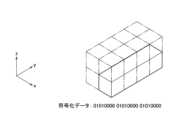
図1に示すように、点を含むブロックがy軸方向に並んでいるとする。これらのブロックを含む立方体を分割して符号化する。以下では、分割数nを4として説明する。 As shown in FIG. 1, it is assumed that blocks including points are lined up in the y-axis direction. The cube containing these blocks is divided and encoded. In the following description, the number of divisions n is assumed to be four.
図2に立方体の分割例を示す。図2の例では、立方体がz軸方向に4つの4×4ブロック面に分割されている。4×4ブロック面それぞれの点の占有状態について、点を含む立体を1、点を含まない立体を0で表す。z軸の正の方向を上位ビットとして、立方体を4分割した各立体の点の占有状態を表した数値を並べると、立方体は“0001”と表される。 Figure 2 shows an example of dividing a cube. In the example of FIG. 2, the cube is divided into four 4×4 block planes in the z-axis direction. Regarding the occupancy state of points on each 4×4 block plane, a solid that includes a point is represented by 1, and a solid that does not contain a point is represented by 0. When the numerical values representing the occupancy states of the points in each of the cubes divided into four parts are arranged with the positive direction of the z-axis as the upper bit, the cube is expressed as "0001".
4つの4×4ブロック面のうち点を含む4×4ブロック面がさらに分割されて符号化される。図2の例では、一番下の4×4ブロック面のみがさらに分割される。 Among the four 4×4 block planes, the 4×4 block plane including the points is further divided and encoded. In the example of FIG. 2, only the
図3に4×4ブロック面の分割例を示す。図3の例では、4×4ブロック面がx軸方向に4つの4×1ブロック列に分割されている。4×1ブロック列それぞれの点の占有状態について、点を含む立体を1、点を含まない立体を0で表す。x軸の正の方向を上位ビットとして、4×4ブロック面を4分割した各立体の点の占有状態を表した数値を並べると、図3の4×4ブロック面は“1000”と表される。 FIG. 3 shows an example of dividing a 4×4 block plane. In the example of FIG. 3, the 4×4 block surface is divided into four 4×1 block rows in the x-axis direction. Regarding the occupancy state of points in each 4×1 block row, a solid that includes a point is represented by 1, and a solid that does not contain a point is represented by 0. When the positive direction of the x-axis is taken as the upper bit, and the numerical values representing the occupancy status of each solid point obtained by dividing the 4 × 4 block plane into four are arranged, the 4 × 4 block plane in Figure 3 is expressed as “1000”. Ru.
4つの4×1ブロック列のうち点を含む4×1ブロック列がさらに分割されて符号化される。図3の例では、一番右の4×1ブロック列のみがさらに分割される。 Among the four 4×1 block sequences, the 4×1 block sequence including the points is further divided and encoded. In the example of FIG. 3, only the rightmost 4×1 block column is further divided.
図4に4×1ブロック列の分割例を示す。図4の例では、4×1ブロック列がy軸方向に4つのブロックに分割されている。ブロックそれぞれの点の占有状態について、点を含む立体を1、点を含まない立体を0で表す。y軸の正の方向を上位ビットとして、4×1ブロック列を4分割した各立体の点の占有状態を表した数値を並べると、図4の4×1ブロック列は“1111”と表される。 FIG. 4 shows an example of dividing a 4×1 block sequence. In the example of FIG. 4, a 4×1 block row is divided into four blocks in the y-axis direction. Regarding the occupancy state of each point in each block, a solid that includes a point is represented by 1, and a solid that does not contain a point is represented by 0. When the positive direction of the y-axis is taken as the upper bit, and the numerical values representing the occupancy status of each solid point obtained by dividing the 4 × 1 block row into 4 are arranged, the 4 × 1 block row in Fig. 4 is expressed as “1111”. Ru.
各立体を符号化した数値を並べると本実施形態の符号化データが得られる。図1の立方体は“0001 1000 1111”と12ビットで表される。このデータに、立方体を分割した順番、つまり復号する順番を示すヘッダが付与される。上記の例では、立方体をz軸、x軸、y軸の順に復号することを示すヘッダが付与される。 By arranging the numerical values encoded for each solid, the encoded data of this embodiment is obtained. The cube in FIG. 1 is represented by 12 bits as "0001 1000 1111". A header indicating the order in which the cube was divided, that is, the order in which it is decoded, is added to this data. In the above example, a header is added indicating that the cube is to be decoded in the order of the z-axis, x-axis, and y-axis.
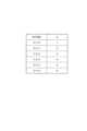
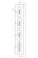
図5に符号化データの構造の一例を示す。図5の符号化データは、ヘッダ、第1符号化データ、第2符号化データ、および第3符号化データで構成される。ヘッダは、復号方法と復号方向を示す復号情報を含む。図6に復号情報の一例を示す。図6の例では、0は従来の八分木で復号することを表す。1から6は復号方向の順番を表す。例えば、図1~4の例では、z軸、x軸、y軸の順に復号するので、復号情報の値は5となる。なお、図5の符号化データの構成および図6のヘッダは一例であり、これに限るものではない。 FIG. 5 shows an example of the structure of encoded data. The encoded data in FIG. 5 includes a header, first encoded data, second encoded data, and third encoded data. The header includes decoding information indicating the decoding method and decoding direction. FIG. 6 shows an example of decoding information. In the example of FIG. 6, 0 represents decoding using a conventional octree. 1 to 6 represent the order in the decoding direction. For example, in the examples shown in FIGS. 1 to 4, the z-axis, x-axis, and y-axis are decoded in this order, so the value of the decoding information is 5. Note that the configuration of the encoded data in FIG. 5 and the header in FIG. 6 are examples, and are not limited to these.
第1符号化データは、立方体をn分割したn×nブロック面それぞれの点の占有状態を符号化したデータである。図1~4の例では、立方体をz軸方向に4分割して得られた4つのn×nブロック面それぞれの点の占有状態を符号化した“0001”が第1符号化データである。 The first encoded data is data obtained by encoding the occupancy state of each point on an n×n block surface obtained by dividing a cube into n. In the examples shown in FIGS. 1 to 4, the first encoded data is "0001" which encodes the occupancy state of each point on each of the four n×n block surfaces obtained by dividing the cube into four in the z-axis direction.
第2符号化データは、点を含むn×nブロック面それぞれをn分割したn×1ブロック列それぞれの点の占有状態を符号化したデータである。図1~4の例では、4×4ブロック面をx軸方向に4分割して得られた4つのn×1ブロック列それぞれの点の占有状態を符号化した“0001”が第2符号化データである。第2符号化データは、点を含むn×nブロック面の数分存在する。例えば、2つのn×nブロック面が点を含む場合、第2符号化データは2つ存在し、所定の順番で並べられる。 The second encoded data is data obtained by encoding the occupancy state of points in each n×1 block row obtained by dividing each n×n block surface including points into n parts. In the examples shown in Figures 1 to 4, "0001", which encodes the occupancy state of each point in four nx1 block columns obtained by dividing the 4x4 block plane into four in the x-axis direction, is the second encoding. It is data. The second encoded data exists for the number of n×n block planes including points. For example, when two n×n block planes include points, two pieces of second encoded data exist and are arranged in a predetermined order.
第3符号化データは、点を含むn×1ブロック列それぞれをn分割したブロックそれぞれの点の占有状態を符号化したデータである。図1~4の例では、4×1ブロック列をy軸方向に4分割して得られた4つのブロックそれぞれの点の占有状態を符号化した“1111”が第3符号化データである。第3符号化データは、点を含むn×1ブロック列の数分存在する。複数の第3符号化データは所定の順番で並べられる。 The third encoded data is data obtained by encoding the occupancy state of points in each block obtained by dividing each n×1 block string including points into n blocks. In the examples shown in FIGS. 1 to 4, the third encoded data is "1111" which encodes the occupancy state of each of the four blocks obtained by dividing the 4×1 block sequence into four in the y-axis direction. The third encoded data exists for the number of n×1 block sequences including points. The plurality of third encoded data are arranged in a predetermined order.
なお、復号情報の値が0の場合、ヘッダに続くデータは、立方体の各辺を2等分して分割した8つの立方体それぞれの点の占有状態である。点の占有状態を0か1の1ビットとすると、1階層分の八分木構造のデータは8ビットの数値で表される。本実施形態の符号化データの分割数nを8とすると、第1符号化データ、第2符号化データ、および第3符号化データのいずれも8ビットの数値となるので、八分木構造のデータと親和性が高くなる。 Note that when the value of the decoding information is 0, the data following the header is the occupancy state of each point of eight cubes obtained by dividing each side of the cube into two equal parts. If the occupancy state of a point is set to 1 bit, 0 or 1, the data of the octree structure for one layer is represented by an 8-bit numerical value. If the number of divisions n of the encoded data in this embodiment is 8, the first encoded data, the second encoded data, and the third encoded data are all 8-bit numerical values, so the octree structure is Greater affinity with data.
次の階層の各ブロック(図4の各ブロック)が分割できるときは、第3符号化データの後に、点を含む各ブロックを符号化した符号化データを追加する。例えば、図4の各ブロックをさらに分割するときは、ブロック4つ分の符号化データが追加される。各ブロックは図1~4と同様に符号化できる。4つのブロックの符号化データのそれぞれは、ヘッダ、第1符号化データ、第2符号化データ、および第3符号化データで構成される。ブロックごとに、本実施形態の符号化データと八分木構造のデータを使い分けてもよい。 When each block of the next layer (each block in FIG. 4) can be divided, encoded data obtained by encoding each block including points is added after the third encoded data. For example, when each block in FIG. 4 is further divided, encoded data for four blocks is added. Each block can be encoded similarly to FIGS. 1-4. Each of the four blocks of encoded data includes a header, first encoded data, second encoded data, and third encoded data. The encoded data of this embodiment and the octree-structured data may be used separately for each block.
さらに下の階層のブロック(図4の各ブロックを分割して得られるブロック)が分割できるときは、ブロックごとに下の階層のブロックの符号化データを追加してもよいし、階層ごとに符号化データをまとめてもよい。 When blocks in a lower hierarchy (blocks obtained by dividing each block in Figure 4) can be divided, the encoded data of the blocks in the lower hierarchy may be added to each block, or data may be summarized.
親の立方体(図1の立方体)と子のブロック(図4の各ブロック)の復号方向が同じ場合は、各ブロックの符号化データにヘッダを付与しなくてもよい。例えば、図4の4つのブロックの符号化データのそれぞれは、第1符号化データ、第2符号化データ、および第3符号化データで構成される。これらの符号化データは、z軸方向、x軸方向、y軸方向の順番で復号する。 If the parent cube (the cube in FIG. 1) and the child blocks (each block in FIG. 4) are decoded in the same direction, it is not necessary to add a header to the encoded data of each block. For example, each of the four blocks of encoded data in FIG. 4 is composed of first encoded data, second encoded data, and third encoded data. These encoded data are decoded in the order of the z-axis direction, the x-axis direction, and the y-axis direction.
同じ階層で復号方向が同じ場合は、階層ごとにヘッダを付与してもよい。例えば、階層の1番目の符号化データのみにヘッダを付与し、残りの符号化データにはヘッダを付与しない。 If the decoding direction is the same in the same layer, a header may be added to each layer. For example, a header is attached only to the first encoded data in the hierarchy, and no header is attached to the remaining encoded data.
[復号装置の構成]
図7を参照し、本実施形態の復号装置について説明する。図7に示す復号装置10は、復号方向判定部11、第1復号部12、第2復号部13、および第3復号部14を備える。[Decoding device configuration]
The decoding device of this embodiment will be described with reference to FIG. 7. The
復号方向判定部11は、復号する順序に応じた方向を判定する。以下では、復号する順序に応じた方向を第1方向、第2方向、第3方向とする。第1方向、第2方向、第3方向のそれぞれは、x軸方向、y軸方向、z軸方向のいずれかである。 The decoding
第1復号部12は、立方体を第1方向にn分割したn個のn×nブロック面それぞれの点の占有状態を得る。 The
第2復号部13は、n×nブロック面の点の占有状態に応じて、点を含むn×nブロック面を第2方向にn分割したn個のn×1ブロック列それぞれの点の占有状態を得る。 The
第3復号部14は、n×1ブロック列の点の占有状態に応じて、点を含むn×1ブロック列を第3方向にn分割したn個のブロックそれぞれの点の占有状態を得る。 The
ブロックをさらに分割できるときは、点を含むブロックつまり図5の第3符号化データに続く次のブロックの符号化データを復号方向判定部11に入力する。ブロックが分割できないときは、ブロックの点の占有状態が点群データを示す。 When the block can be further divided, the block including the point, that is, the encoded data of the next block following the third encoded data in FIG. 5 is input to the decoding
[復号装置の処理]
図8のフローチャートを参照し、復号装置10の処理の流れについて説明する。[Decoding device processing]
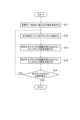
The process flow of the
ステップS1にて、復号装置10は、入力した符号化データの復号方法を取得し、ステップS2にて、復号方法は従来方法であるか否か判定する。復号方法は、ヘッダを参照することで判定できる。また、復号方向もヘッダから得ることができる。 In step S1, the
復号方法が従来方法の場合、ステップS3にて、従来方法でヘッダに続くデータを復号する。 If the decoding method is the conventional method, the data following the header is decoded using the conventional method in step S3.
符号化データが復号装置10の復号対象の場合、ステップS4にて、第1復号部12は、第1符号化データから、8×8×8ブロック(立方体)を第1方向に分割した8×8ブロック面の点の占有状態を得る。分割数n(ここではn=8)は、事前に指定されてもよいし、ヘッダで指定されてもよい。 When the encoded data is to be decoded by the
例えば、第1方向がx軸のとき、図9に示すように、立方体はx軸方向に8つの8×8ブロック面に分割されて符号化されている。8×8ブロック面の点の占有状態を1ビットで表すと、x軸の正の方向を上位ビットとした8ビットの数値(0~255)で立方体は符号化されている。 For example, when the first direction is the x-axis, as shown in FIG. 9, the cube is divided into eight 8×8 block planes in the x-axis direction and encoded. If the occupancy state of a point on an 8×8 block surface is expressed by one bit, the cube is encoded with an 8-bit numerical value (0 to 255) with the positive direction of the x-axis as the upper bit.
点を含まない8×8ブロック面は、以下のステップS5以降の処理対象としない。 An 8×8 block plane that does not include any points is not subject to processing in step S5 and subsequent steps.
ステップS5にて、8×8ブロック面のうち点を含む8×8ブロック面について、第2復号部13は、第2符号化データから、8×8ブロック面を第2方向に分割した8×1ブロック列の点の占有状態を得る。 In step S5, for the 8×8 block plane including points among the 8×8 block planes, the
例えば、第2方向がy軸のとき、図10に示すように、8×8ブロック面はy軸方向に8つの8×1ブロック列に分割されて符号化されている。8×1ブロック列の点の占有状態を1ビットで表すと、y軸の正の方向を上位ビットとした8ビットの数値(0~255)で8×8ブロック面は符号化されている。 For example, when the second direction is the y-axis, as shown in FIG. 10, the 8×8 block plane is divided into eight 8×1 block columns in the y-axis direction and encoded. If the occupancy state of a point in an 8×1 block row is expressed by one bit, the 8×8 block surface is encoded with an 8-bit numerical value (0 to 255) with the positive direction of the y-axis as the upper bit.
点を含まない8×1ブロック列は、以下のステップS6以降の処理対象としない。 An 8×1 block sequence that does not include any points is not processed in step S6 and subsequent steps.
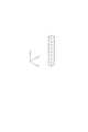
ステップS6にて、8×1ブロック列のうち点を含む8×1ブロック列について、第3復号部14は、第3符号化データから、8×1ブロック列を第3方向に分割したブロックの点の占有状態を得る。 In step S6, for the 8×1 block string including points among the 8×1 block strings, the
例えば、第3方向がz軸のとき、図11に示すように、8×1ブロック列はz軸方向に8つのブロックに分割されて符号化されている。ブロックの点の占有状態を1ビットで表すと、z軸の正の方向を上位ビットとした8ビットの数値(0~255)で8×1ブロック列は符号化されている。 For example, when the third direction is the z-axis, as shown in FIG. 11, an 8×1 block sequence is divided into eight blocks in the z-axis direction and encoded. If the occupancy state of a point in a block is represented by one bit, an 8×1 block string is encoded with an 8-bit numerical value (0 to 255) with the positive direction of the z-axis as the upper bit.
ステップS7にて、ステップS6で得られたブロックがさらに分割できるか否かを判定する。従来方法で復号した場合は、ステップS3で分割後のブロックがさらに分割できるか否かを判定する。 In step S7, it is determined whether the block obtained in step S6 can be further divided. When decoding is performed using the conventional method, it is determined in step S3 whether the divided block can be further divided.
ブロックがさらに分割できる場合、そのブロックを符号化したデータについて、ステップS1からの処理を繰り返す。具体的には、図7の次のブロック以降のデータについてステップS1からの処理を繰り返す。 If the block can be further divided, the processing from step S1 is repeated for the encoded data of that block. Specifically, the process from step S1 is repeated for the data from the next block onwards in FIG.
[符号化方法]
本実施形態では、分割後の各立体内の点の占有状態の相関が高くなる方向に立体をn分割し、分割後の立体内の点の占有状態に基づいて符号化する。例えば、立体をn分割したときに、分割後のn個の立体のうち点を含まない立体が多くなるように分割方向を決定する。このとき、n分割可能なn×1ブロック列(1×1×n,1×n×1,n×1×1のいずれでもよい)が最小単位(最小の立体)となる。または、点の占有状態の相関が高くなるように、n個のブロックを一方向に並べてn×1ブロック列を作成し、各ブロックの点の占有状態に応じてn×1ブロック列を符号化する。上の階層では、作成するブロック群内の点の占有状態の相関が高くなる方向に、n個のn×1ブロック列を並べて、各n×1ブロック列内の点の占有状態に応じて作成したブロック群を符号化する。さらに上の階層では、点の占有状態の相関が高くなる方向に下の階層のブロック群を並べて符号化する。いずれにおいても、立体を一方向にn分割した各立体の点の占有状態に基づいて符号化されるものであり、本実施例としての選択可能な最小単位はn×1ブロック列である。ただし、符号化対象の点の占有状態により、実施例としての最小単位よりも大きな単位で符号化される場合も当然ある。以下、分割数nを8とした符号化方法について説明する。[Encoding method]
In this embodiment, a solid is divided into n parts in a direction that increases the correlation between the occupancy states of points within each solid after division, and encoding is performed based on the occupancy states of points within the divided solid. For example, when a solid is divided into n parts, the division direction is determined so that the number of solids that do not include a point is large among the n solids after division. At this time, an n×1 block sequence (which may be 1×1×n, 1×n×1, or n×1×1) that can be divided into n becomes the minimum unit (minimum solid). Alternatively, create an n×1 block sequence by arranging n blocks in one direction so that the correlation between the point occupancy states is high, and encode the n×1 block sequence according to the point occupancy state of each block. do. In the upper layer,
図12のフローチャートを参照し、点群データの符号化方法の一例について説明する。 An example of a method for encoding point cloud data will be described with reference to the flowchart in FIG. 12.
ステップS11にて、点群データを全て含み、1辺が8のk乗のうち最小となる立方体を生成する。分割数nは8、階層の数はkである。 In step S11, a cube is generated that includes all the point group data and has one side that is the smallest among 8 raised to the k power. The number of divisions n is 8, and the number of layers is k.
ステップS12にて、図13に示すように、xyz軸方向にそれぞれ8分割する。つまり、立方体を8×8×8個のブロックに分割する。 In step S12, as shown in FIG. 13, the image is divided into eight parts in each of the x, y, and z axis directions. That is, the cube is divided into 8x8x8 blocks.
ステップS13にて、xyz軸方向のいずれかのうち、当該空間に点がある、もしくは点が無い相関が最も高くなる方向に8つのブロックをまとめて8×1ブロック列を作成する。例えば、点を含まないブロックだけで構成される8×1ブロック列の数が多くなる方向に、8×1ブロック列を作成する。前出の図11で示した例では、z軸方向にブロックをまとめて8×1ブロック列を作成した。全てのブロックが同じ方向(図11の例ではz軸方向)にまとめられて、64個の8×1ブロック列が作成される。 In step S13, eight blocks are grouped together in one of the x, y, and z axes in the direction in which the correlation with a point or no point in the space is highest to create an 8×1 block sequence. For example, 8x1 block rows are created in the direction in which the number of 8x1 block rows consisting only of blocks that do not include points increases. In the example shown in FIG. 11 mentioned above, blocks are grouped together in the z-axis direction to create an 8×1 block row. All blocks are grouped in the same direction (in the example of FIG. 11, the z-axis direction) to create 64 8×1 block columns.
ステップS14にて、ステップS13でブロックをまとめた方向以外のいずれかの方向に8つの8×1ブロック列をまとめて8×8ブロック面を作成する。例えば、点を含まないブロックだけで構成される8×8ブロック面の数が多くなる方向に、8×8ブロック面を作成する。前出の図10に示した例では、y軸方向に8×1ブロック列をまとめて8×8ブロック面を作成した。全ての8×1ブロック列が同じ方向(図10の例ではy軸方向)にまとめられて、8個の8×8ブロック面が作成される。 In step S14, eight 8×1 block rows are grouped together in any direction other than the direction in which the blocks were grouped in step S13 to create an 8×8 block surface. For example, 8×8 block planes are created in the direction in which the number of 8×8 block planes composed only of blocks that do not include points increases. In the example shown in FIG. 10 mentioned above, 8×1 block rows are grouped together in the y-axis direction to create an 8×8 block surface. All 8×1 block rows are grouped in the same direction (in the example of FIG. 10, the y-axis direction) to create eight 8×8 block planes.
8個の8×8ブロック面をまとめると元の立方体となる。 When the eight 8x8 block faces are put together, it becomes the original cube.
以上の処理により、立方体を分割する方向の順番と分割後の各立体の点の占有状態が決まるので、点群データを含む立方体を符号化できる。 Through the above processing, the order of the directions in which the cube is divided and the occupation state of the points of each solid after the division are determined, so that the cube containing point group data can be encoded.
また、ステップS15にて、ブロックがさらに分割できるか否か判定する。分割できるときは、点を含むブロックのそれぞれについて、ステップS12からステップS14の処理を繰り返して下の階層の各ブロックを符号化する。なお、ステップS12からステップS14の処理はk回繰り返される。 Furthermore, in step S15, it is determined whether the block can be further divided. When it is possible to divide, the processes from step S12 to step S14 are repeated for each block including points, and each block in the lower hierarchy is encoded. Note that the processing from step S12 to step S14 is repeated k times.
図14のフローチャートを参照し、点群データの符号化方法の別の例について説明する。 Another example of the method for encoding point cloud data will be described with reference to the flowchart in FIG. 14.
ステップS21にて、単位ブロックを最小とする。例えば、点群データの1つの点を含む立方体を最小の単位ブロックとする。 In step S21, the unit block is minimized. For example, the smallest unit block is a cube containing one point of point group data.
ステップS22にて、空間内の点の占有状態の相関が高い方向(x軸方向、y軸方向、z軸方向のいずれか)に、単位ブロックを8個まとめて8×1ブロック列を作成する。 In step S22, eight unit blocks are grouped together in a direction (either the x-axis direction, the y-axis direction, or the z-axis direction) in which the correlation between the occupancy states of points in the space is high to create an 8×1 block array. .
ステップS23にて、含まれるブロック列の相関が高くなる方向(ステップS22の方向と直交する方向)に、8×1ブロック列を8個まとめて8×8ブロック面を作成する。 In step S23, eight 8×1 block columns are combined to create an 8×8 block plane in a direction in which the correlation between the included block columns increases (a direction perpendicular to the direction in step S22).
ステップS24にて、8×8ブロック面を8個まとめて8×8×8ブロックの立方体を作成する。 In step S24, eight 8x8 block faces are put together to create an 8x8x8 block cube.
ステップS25にて、立方体に全ての点群データが含まれているか否か判定する。 In step S25, it is determined whether all the point group data is included in the cube.
立方体に全ての点群データが含まれている場合は、立方体を分割する方向の順番と分割後の各立体の点の占有状態が決まるので、点群データを含む立方体を符号化できる。 If the cube contains all the point group data, the order of the directions in which the cube is divided and the occupation status of the points of each solid after the division are determined, so the cube containing the point group data can be encoded.
立方体に全ての点群データが含まれていない場合は、ステップS26にて、8×8×8ブロックを単位ブロックとして、ステップS22からの処理を繰り返す。 If the cube does not contain all the point group data, in step S26, the process from step S22 is repeated using an 8×8×8 block as a unit block.
なお、符号化方法は上記のものに限らず、様々な符号化方法を用いることができる。例えば、6通りの全ての順番で符号化し、最も符号化効率のよい順番を採用する。 Note that the encoding method is not limited to the one described above, and various encoding methods can be used. For example, encoding is performed in all six orders, and the order with the highest encoding efficiency is adopted.
[八分木との比較]
次に、本実施形態の復号方法を用いて復号する符号化データと八分木で符号化したデータの符号化効率を比較する。[Comparison with octree]
Next, the encoding efficiency of encoded data decoded using the decoding method of this embodiment and data encoded using an octree will be compared.
図15,16を参照し、図1で示した4つのブロックを含む立方体を八分木で符号化したデータについて説明する。 With reference to FIGS. 15 and 16, data obtained by encoding the cube including the four blocks shown in FIG. 1 using an octree will be described.
図15に示すように、八分木構造では、立方体の各辺を2等分して8つの立方体に分割する。8つの立方体のそれぞれに、位置に応じて0番から7番の番号を付与する。具体的には、図15の左側の縦に並んだ2つの立方体を下から順に0番と1番とし、奥の縦に並んだ2つの立方体を下から順に2番と3番とし、手前の縦に並んだ2つの立方体を下から順に4番と5番とし、右側の縦に並んだ2つの立方体を下から順に6番と7番とする。立方体それぞれの点の占有状態について、点を含む立方体を1、点を含まない立方体を0で表す。立方体の番号順に、各立方体の点の占有状態を表した数値を下位ビットから並べると、立方体は“01010000”と表される。 As shown in FIG. 15, in the octree structure, each side of a cube is bisected into eight cubes. Give each of the eight cubes a number from 0 to 7 depending on its position. Specifically, the two vertically arranged cubes on the left side of Figure 15 are numbered 0 and 1 from the bottom, the two vertically arranged cubes in the back are numbered 2 and 3 from the bottom, and the one in the front is numbered 0 and 1 from the bottom. The two vertically aligned cubes are numbered 4 and 5 from the bottom, and the two vertically aligned cubes on the right side are numbered 6 and 7 from the bottom. Regarding the occupancy state of each point in a cube, a cube that contains a point is represented by 1, and a cube that does not contain a point is represented by 0. When the numerical values representing the occupancy status of the points of each cube are arranged from the least significant bit in the order of the cube number, the cube is expressed as "01010000".
図16に示すように、点を含む4番と6番の立方体のそれぞれは、さらに8つの立方体に分割されて同様に符号化される。4番と6番の立方体のいずれも“01010000”と表される。 As shown in FIG. 16, each of the cubes No. 4 and No. 6 containing the points is further divided into eight cubes and similarly encoded. Both cubes No. 4 and No. 6 are represented as "01010000".
立方体を符号化した数値を階層ごとに並べると、“01010000 01010000 01010000”と24ビットで表される。前出のように、本実施形態の符号化データは12ビットであり、八分木よりも符号量を削減できる可能性がある。 When the numerical values obtained by encoding the cube are arranged for each layer, they are expressed in 24 bits as "01010000 01010000 01010000". As mentioned above, the encoded data of this embodiment is 12 bits, and there is a possibility that the amount of code can be reduced compared to the octree.
以上説明したように、本実施形態の復号装置10は、3次元の点群データを含む立方体を第1方向、第2方向、第3方向の順にn(nは2以上の整数)分割して点の占有状態を符号化した符号化データから点群データを復号する。復号装置10は、立方体を分割した順番に応じた第1方向、第2方向、第3方向を判定する復号方向判定部11と、立方体を第1方向にn分割したn個のn×nブロック面それぞれの点の占有状態を得る第1復号部12と、n×nブロック面それぞれの点の占有状態に応じて、n×nブロック面を第2方向にn分割したn個のn×1ブロック列それぞれの点の占有状態を得る第2復号部13と、n×1ブロック列それぞれの点の占有状態に応じて、n×1ブロック列を第3方向にn分割したn個のブロックそれぞれの点の占有状態を得る第3復号部14を備える。これにより、点群データを八分木構造で表現したときよりも、符号化効率を向上できる場合がある。例えば、床または柱などの3次元物体を表現する際に符号化効率を向上できる。 As explained above, the
上記説明した復号装置10には、例えば、図17に示すような、中央演算処理装置(CPU)901と、メモリ902と、ストレージ903と、通信装置904と、入力装置905と、出力装置906とを備える汎用的なコンピュータシステムを用いることができる。このコンピュータシステムにおいて、CPU901がメモリ902上にロードされた所定のプログラムを実行することにより、復号装置10が実現される。このプログラムは磁気ディスク、光ディスク、半導体メモリ等のコンピュータ読み取り可能な記録媒体に記録することも、ネットワークを介して配信することもできる。 The
10…復号装置
11…復号方向判定部
12…第1復号部
13…第2復号部
14…第3復号部10...Decoding
Claims (6)
Translated fromJapaneseコンピュータが、
復号する順番に応じた第1方向、第2方向、第3方向を判定するステップと、
前記立方体を前記第1方向にn分割したn個の第1ブロック群それぞれの点の占有状態を得るステップと、
前記第1ブロック群それぞれの点の占有状態に応じて、当該第1ブロック群を前記第2方向にn分割したn個の第2ブロック群それぞれの点の占有状態を得るステップと、
前記第2ブロック群それぞれの点の占有状態に応じて、当該第2ブロック群を前記第3方向にn分割したn個のブロックそれぞれの点の占有状態を得るステップを実行する
復号方法。A cube containing three-dimensional point cloud data is divided into n parts (n is an integer of 2 or more) in the order of the first direction, second direction, and third direction, and the point occupancy state is encoded. A decryption method for decrypting data, the method comprising:
The computer is
determining a first direction, a second direction, and a third direction according to the order of decoding;
obtaining an occupancy state of a point in each of n first block groups obtained by dividing the cube into n in the first direction;
obtaining the occupancy state of points of each of n second block groups obtained by dividing the first block group into n in the second direction according to the occupancy state of each point of the first block group;
A decoding method comprising the step of obtaining the occupancy state of points in each of n blocks obtained by dividing the second block group into n blocks in the third direction, according to the occupancy state of each point in the second block group.
nは8である
復号方法。The decoding method according to claim1 , comprising:
n is 8 Decoding method.
前記第3方向にn分割したn個のブロックのそれぞれを符号化した符号化データを復号する
復号方法。The decoding method according to claim1 or 2 ,
A decoding method for decoding encoded data obtained by encoding eachof n blocks divided into n blocks in the third direction .
前記符号化データは、n個のブロックごとに前記復号する順番を判定するための情報を保持する
復号方法。The decoding method according to claim3 ,
The encoded data holds information for determining the decoding order foreach n block .
復号する順番に応じた第1方向、第2方向、第3方向を判定する復号方向判定部と、
前記立方体を前記第1方向にn分割したn個の第1ブロック群それぞれの点の占有状態を得る第1復号部と、
前記第1ブロック群それぞれの点の占有状態に応じて、当該第1ブロック群を前記第2方向にn分割したn個の第2ブロック群それぞれの点の占有状態を得る第2復号部と、
前記第2ブロック群それぞれの点の占有状態に応じて、当該第2ブロック群を前記第3方向にn分割したn個のブロックそれぞれの点の占有状態を得る第3復号部を備える
復号装置。A cube containing three-dimensional point cloud data is divided into n parts (n is an integer of 2 or more) in the order of the first direction, second direction, and third direction, and the point occupancy state is encoded. A decoding device for decoding data, the decoding device comprising:
a decoding direction determination unit that determines a first direction, a second direction, and a third direction according to the order of decoding;
a first decoding unit that obtains an occupancy state of a point in each of n first block groups obtained by dividing the cube into n in the first direction;
a second decoding unit that obtains the occupancy state of points of each of n second block groups obtained by dividing the first block group into n in the second direction according to the occupancy state of each point of the first block group;
A decoding device comprising: a third decoding unit that obtains the occupancy state of points in each of n blocks obtained by dividing the second block group into n blocks in the third direction, according to the occupancy state of each point in the second block group.
Applications Claiming Priority (1)
| Application Number | Priority Date | Filing Date | Title |
|---|---|---|---|
| PCT/JP2019/048108WO2021117092A1 (en) | 2019-12-09 | 2019-12-09 | Decoding method, decoding device, and program |
Publications (2)
| Publication Number | Publication Date |
|---|---|
| JPWO2021117092A1 JPWO2021117092A1 (en) | 2021-06-17 |
| JP7393679B2true JP7393679B2 (en) | 2023-12-07 |
Family
ID=76328913
Family Applications (1)
| Application Number | Title | Priority Date | Filing Date |
|---|---|---|---|
| JP2021563457AActiveJP7393679B2 (en) | 2019-12-09 | 2019-12-09 | Decoding method, decoding device and program |
Country Status (3)
| Country | Link |
|---|---|
| US (1) | US20230011947A1 (en) |
| JP (1) | JP7393679B2 (en) |
| WO (1) | WO2021117092A1 (en) |
Citations (3)
| Publication number | Priority date | Publication date | Assignee | Title |
|---|---|---|---|---|
| JP2002165217A (en) | 2000-11-28 | 2002-06-07 | Kddi Corp | Hierarchical encoding transmission method and hierarchical decoding method for three-dimensional image |
| US20190116357A1 (en) | 2017-10-12 | 2019-04-18 | Mitsubishi Electric Research Laboratories, Inc. | System and method for Inter-Frame Predictive Compression for Point Clouds |
| WO2019230920A1 (en) | 2018-06-01 | 2019-12-05 | パナソニック インテレクチュアル プロパティ コーポレーション オブ アメリカ | Three-dimensional data encoding method, three-dimensional data decoding method, three-dimensional data encoding device, and three-dimensional data decoding device |
Family Cites Families (1)
| Publication number | Priority date | Publication date | Assignee | Title |
|---|---|---|---|---|
| CA3134855A1 (en)* | 2019-06-26 | 2020-12-30 | Tencent America LLC | Implicit quadtree or binary-tree geometry partition for point cloud coding |
- 2019
- 2019-12-09JPJP2021563457Apatent/JP7393679B2/enactiveActive
- 2019-12-09WOPCT/JP2019/048108patent/WO2021117092A1/ennot_activeCeased
- 2019-12-09USUS17/783,496patent/US20230011947A1/ennot_activeAbandoned
Patent Citations (3)
| Publication number | Priority date | Publication date | Assignee | Title |
|---|---|---|---|---|
| JP2002165217A (en) | 2000-11-28 | 2002-06-07 | Kddi Corp | Hierarchical encoding transmission method and hierarchical decoding method for three-dimensional image |
| US20190116357A1 (en) | 2017-10-12 | 2019-04-18 | Mitsubishi Electric Research Laboratories, Inc. | System and method for Inter-Frame Predictive Compression for Point Clouds |
| WO2019230920A1 (en) | 2018-06-01 | 2019-12-05 | パナソニック インテレクチュアル プロパティ コーポレーション オブ アメリカ | Three-dimensional data encoding method, three-dimensional data decoding method, three-dimensional data encoding device, and three-dimensional data decoding device |
Also Published As
| Publication number | Publication date |
|---|---|
| US20230011947A1 (en) | 2023-01-12 |
| JPWO2021117092A1 (en) | 2021-06-17 |
| WO2021117092A1 (en) | 2021-06-17 |
Similar Documents
| Publication | Publication Date | Title |
|---|---|---|
| JP7330306B2 (en) | Transform method, inverse transform method, encoder, decoder and storage medium | |
| TWI546770B (en) | Fully parallel in-place construction of 3d acceleration structures in a graphics processing unit | |
| JP5955378B2 (en) | Encoding method and decoding method | |
| WO2021258374A1 (en) | Method for encoding and decoding a point cloud | |
| KR101654777B1 (en) | Apparatus and method for scalable encoding 3d mesh, and apparatus and method for scalable decoding 3d mesh | |
| US9607434B2 (en) | Apparatus and method for encoding three-dimensional (3D) mesh, and apparatus and method for decoding 3D mesh | |
| KR102759134B1 (en) | Context Determination for Planar Mode in Octree-Based Point Cloud Coding | |
| KR20180000279A (en) | Apparatus and method for encoding, apparatus and method for decoding | |
| WO2021065536A1 (en) | Information processing device and method | |
| CN110288664B (en) | Coding device, decoding device, and non-transitory computer readable medium | |
| KR20120085066A (en) | Data processing apparatus and method | |
| KR102256913B1 (en) | 3d dynamic point cloud compression method | |
| KR102799223B1 (en) | Methods for predicting attribute information, encoders, decoders and storage media | |
| US8098247B2 (en) | Systems and methods for geometric data compression and encryption | |
| WO2022054358A1 (en) | Point group decoding device, point group decoding method, and program | |
| US10373384B2 (en) | Lightfield compression using disparity predicted replacement | |
| JP7393679B2 (en) | Decoding method, decoding device and program | |
| CN113570677A (en) | Image compression method and device | |
| Kim et al. | Multiresolution random accessible mesh compression | |
| US20200336157A1 (en) | Systematic and xor-based coding technique for distributed storage systems | |
| CN114787720B (en) | Method for encoding a digital hologram, method for encoding a group of digital holograms and associated encoding device | |
| CN115391351B (en) | A multi-layer vector data overlay method based on Spark big data | |
| JP7573555B2 (en) | Point group decoding device, point group decoding method and program | |
| WO2023167153A1 (en) | Information processing device and information processing method | |
| JP2024533637A (en) | Compressing point cloud data frames |
Legal Events
| Date | Code | Title | Description |
|---|---|---|---|
| A621 | Written request for application examination | Free format text:JAPANESE INTERMEDIATE CODE: A621 Effective date:20220426 | |
| A131 | Notification of reasons for refusal | Free format text:JAPANESE INTERMEDIATE CODE: A131 Effective date:20230627 | |
| A521 | Request for written amendment filed | Free format text:JAPANESE INTERMEDIATE CODE: A523 Effective date:20230815 | |
| TRDD | Decision of grant or rejection written | ||
| A01 | Written decision to grant a patent or to grant a registration (utility model) | Free format text:JAPANESE INTERMEDIATE CODE: A01 Effective date:20231024 | |
| A61 | First payment of annual fees (during grant procedure) | Free format text:JAPANESE INTERMEDIATE CODE: A61 Effective date:20231106 | |
| R150 | Certificate of patent or registration of utility model | Ref document number:7393679 Country of ref document:JP Free format text:JAPANESE INTERMEDIATE CODE: R150 | |
| S533 | Written request for registration of change of name | Free format text:JAPANESE INTERMEDIATE CODE: R313533 |