JP7393568B1 - Information processing system and control method - Google Patents
Information processing system and control methodDownload PDFInfo
- Publication number
- JP7393568B1 JP7393568B1JP2023000173AJP2023000173AJP7393568B1JP 7393568 B1JP7393568 B1JP 7393568B1JP 2023000173 AJP2023000173 AJP 2023000173AJP 2023000173 AJP2023000173 AJP 2023000173AJP 7393568 B1JP7393568 B1JP 7393568B1
- Authority
- JP
- Japan
- Prior art keywords
- pen
- image data
- vibration
- unit
- information processing
- Prior art date
- Legal status (The legal status is an assumption and is not a legal conclusion. Google has not performed a legal analysis and makes no representation as to the accuracy of the status listed.)
- Active
Links
Images


Classifications
- G—PHYSICS
- G06—COMPUTING OR CALCULATING; COUNTING
- G06F—ELECTRIC DIGITAL DATA PROCESSING
- G06F3/00—Input arrangements for transferring data to be processed into a form capable of being handled by the computer; Output arrangements for transferring data from processing unit to output unit, e.g. interface arrangements
- G06F3/01—Input arrangements or combined input and output arrangements for interaction between user and computer
- G06F3/03—Arrangements for converting the position or the displacement of a member into a coded form
- G06F3/033—Pointing devices displaced or positioned by the user, e.g. mice, trackballs, pens or joysticks; Accessories therefor
- G06F3/038—Control and interface arrangements therefor, e.g. drivers or device-embedded control circuitry
- G06F3/0383—Signal control means within the pointing device
- G—PHYSICS
- G06—COMPUTING OR CALCULATING; COUNTING
- G06F—ELECTRIC DIGITAL DATA PROCESSING
- G06F3/00—Input arrangements for transferring data to be processed into a form capable of being handled by the computer; Output arrangements for transferring data from processing unit to output unit, e.g. interface arrangements
- G06F3/01—Input arrangements or combined input and output arrangements for interaction between user and computer
- G06F3/016—Input arrangements with force or tactile feedback as computer generated output to the user
- G—PHYSICS
- G06—COMPUTING OR CALCULATING; COUNTING
- G06F—ELECTRIC DIGITAL DATA PROCESSING
- G06F3/00—Input arrangements for transferring data to be processed into a form capable of being handled by the computer; Output arrangements for transferring data from processing unit to output unit, e.g. interface arrangements
- G06F3/01—Input arrangements or combined input and output arrangements for interaction between user and computer
- G06F3/03—Arrangements for converting the position or the displacement of a member into a coded form
- G06F3/033—Pointing devices displaced or positioned by the user, e.g. mice, trackballs, pens or joysticks; Accessories therefor
- G06F3/0354—Pointing devices displaced or positioned by the user, e.g. mice, trackballs, pens or joysticks; Accessories therefor with detection of 2D relative movements between the device, or an operating part thereof, and a plane or surface, e.g. 2D mice, trackballs, pens or pucks
- G06F3/03545—Pens or stylus
- G—PHYSICS
- G06—COMPUTING OR CALCULATING; COUNTING
- G06F—ELECTRIC DIGITAL DATA PROCESSING
- G06F3/00—Input arrangements for transferring data to be processed into a form capable of being handled by the computer; Output arrangements for transferring data from processing unit to output unit, e.g. interface arrangements
- G06F3/01—Input arrangements or combined input and output arrangements for interaction between user and computer
- G06F3/03—Arrangements for converting the position or the displacement of a member into a coded form
- G06F3/041—Digitisers, e.g. for touch screens or touch pads, characterised by the transducing means
- G06F3/0416—Control or interface arrangements specially adapted for digitisers
- G—PHYSICS
- G06—COMPUTING OR CALCULATING; COUNTING
- G06F—ELECTRIC DIGITAL DATA PROCESSING
- G06F3/00—Input arrangements for transferring data to be processed into a form capable of being handled by the computer; Output arrangements for transferring data from processing unit to output unit, e.g. interface arrangements
- G06F3/01—Input arrangements or combined input and output arrangements for interaction between user and computer
- G06F3/048—Interaction techniques based on graphical user interfaces [GUI]
- G06F3/0487—Interaction techniques based on graphical user interfaces [GUI] using specific features provided by the input device, e.g. functions controlled by the rotation of a mouse with dual sensing arrangements, or of the nature of the input device, e.g. tap gestures based on pressure sensed by a digitiser
- G06F3/0488—Interaction techniques based on graphical user interfaces [GUI] using specific features provided by the input device, e.g. functions controlled by the rotation of a mouse with dual sensing arrangements, or of the nature of the input device, e.g. tap gestures based on pressure sensed by a digitiser using a touch-screen or digitiser, e.g. input of commands through traced gestures
- G06F3/04883—Interaction techniques based on graphical user interfaces [GUI] using specific features provided by the input device, e.g. functions controlled by the rotation of a mouse with dual sensing arrangements, or of the nature of the input device, e.g. tap gestures based on pressure sensed by a digitiser using a touch-screen or digitiser, e.g. input of commands through traced gestures for inputting data by handwriting, e.g. gesture or text
- G—PHYSICS
- G06—COMPUTING OR CALCULATING; COUNTING
- G06F—ELECTRIC DIGITAL DATA PROCESSING
- G06F2203/00—Indexing scheme relating to G06F3/00 - G06F3/048
- G06F2203/038—Indexing scheme relating to G06F3/038
- G06F2203/0384—Wireless input, i.e. hardware and software details of wireless interface arrangements for pointing devices
Landscapes
- Engineering & Computer Science (AREA)
- General Engineering & Computer Science (AREA)
- Theoretical Computer Science (AREA)
- Human Computer Interaction (AREA)
- Physics & Mathematics (AREA)
- General Physics & Mathematics (AREA)
- User Interface Of Digital Computer (AREA)
- Position Input By Displaying (AREA)
Abstract
Translated fromJapaneseDescription
Translated fromJapanese本発明は、情報処理システム、及び制御方法に関する。 The present invention relates to an information processing system and a control method.
近年、電子ペン、スマートペン、スタイラス、などとも呼ばれる入力デバイスであるペンと、当該ペンによる手書き入力が可能なタブレット端末などの情報処理装置とを備える情報処理システムが知られている(例えば、特許文献1を参照)。このような情報処理システムでは、ペンが、例えば、振動などを発生するアクチュエータなどを搭載するものがあり、このようなペンを用いて振動を発生させることで、実際に紙にペンで書き込んでいるような触感を再現しようとする試みが行われている。 In recent years, information processing systems have become known that include a pen, which is an input device also called an electronic pen, smart pen, stylus, etc., and an information processing device such as a tablet terminal that can perform handwritten input using the pen (for example, patented (See Reference 1). In such information processing systems, the pen is sometimes equipped with an actuator that generates vibrations, etc., and by using such a pen to generate vibrations, it is possible to actually write on paper with the pen. Efforts are being made to recreate that tactile sensation.
しかしながら、現実の紙とペンとでは複雑な振動が発生するが、上述のような従来の情報処理システムでは、触感の再現が不十分であった。例えば、ペンで描画した描画軌跡の上を、ペンがクロスする場合に、ペンの移動が引っかかる感触など変化が発生するが、従来の情報処理システムでは、ペンが描画軌跡をクロスする際のペン入力の感触に違和感を感じる場合があった。 However, although complex vibrations occur between actual paper and a pen, conventional information processing systems such as those described above are insufficiently able to reproduce the tactile sensation. For example, when a pen crosses a drawing trajectory drawn with a pen, changes occur such as a feeling that the movement of the pen gets stuck, but in conventional information processing systems, pen input when the pen crosses the drawing trajectory There were times when I felt something strange about the touch.
本発明は、上記問題を解決すべくなされたもので、その目的は、ペン入力の違和感を低減することができる情報処理システム、及び制御方法を提供することにある。 The present invention has been made to solve the above problems, and its purpose is to provide an information processing system and a control method that can reduce the discomfort of pen input.
上記問題を解決するために、本発明の一態様は、情報処理装置と、前記情報処理装置と通信可能なペンとを備える情報処理システムであって、前記情報処理装置は、前記ペンの移動軌跡を表示可能な表示部と、前記表示部の画面上における前記ペンの接触位置を検出するタッチセンサ部と、前記タッチセンサ部が検出した前記ペンの接触位置に基づいて、前記ペンが前記画面上に接触して移動した前記画面上の移動軌跡を、前記表示部に表示させる表示処理部と、前記移動軌跡を含む前記表示部が表示する画像データを前記ペンに送信する画像送信処理部と、前記タッチセンサ部が検出した前記ペンの接触位置を、前記ペンに送信する位置送信処理部とを備え、前記ペンは、振動波形信号に基づいて、振動を出力する振動発生器と、前記画像データの前記移動軌跡を含む描画物と、前記ペンの接触位置とが一致した場合に、前記振動波形信号に特定の波形信号を加算して、前記振動発生器に振動を出力させる振動制御部とを備える情報処理システムである。 In order to solve the above problem, one aspect of the present invention is an information processing system including an information processing device and a pen capable of communicating with the information processing device, wherein the information processing device includes a movement trajectory of the pen. a display unit capable of displaying a display unit; a touch sensor unit that detects a contact position of the pen on the screen of the display unit; and a touch sensor unit that detects a contact position of the pen on the screen of the display unit; a display processing unit that causes the display unit to display a movement trajectory on the screen that was moved in contact with the pen; an image transmission processing unit that sends image data displayed by the display unit including the movement trajectory to the pen; a position transmission processing section that transmits a contact position of the pen detected by the touch sensor section to the pen; the pen includes a vibration generator that outputs vibration based on a vibration waveform signal; a vibration control unit that adds a specific waveform signal to the vibration waveform signal and causes the vibration generator to output vibration when a drawn object including the movement trajectory of the pen matches a contact position of the pen; This is an information processing system equipped with
また、本発明の一態様は、上記の情報処理システムにおいて、前記画像送信処理部は、グレイスケールに変換した前記画像データを、前記ペンに送信し、前記振動制御部は、前記画像データにおいて、前記ペンの移動による通過区間の濃淡の階調値が閾値を黒側に超えた場合に、前記振動波形信号に前記特定の波形信号を加算して、前記振動発生器に振動を出力させてもよい。 Further, in one aspect of the present invention, in the above information processing system, the image transmission processing unit transmits the image data converted into gray scale to the pen, and the vibration control unit transmits the image data to the pen. When the gradation value of the light and shade of the passing section due to the movement of the pen exceeds a threshold value toward the black side, the specific waveform signal may be added to the vibration waveform signal to cause the vibration generator to output vibration. good.
また、本発明の一態様は、上記の情報処理システムにおいて、前記画像送信処理部は、定期的に、前記画像データを前記ペンに送信して、前記画像データを更新するようにしてもよい。 Further, in one aspect of the present invention, in the above information processing system, the image transmission processing section may periodically transmit the image data to the pen to update the image data.
また、本発明の一態様は、上記の情報処理システムにおいて、前記画像送信処理部は、定期的に、前記ペンの接触位置の周辺を含む部分画像データを前記ペンに送信して、前記画像データを更新するようにしてもよい。 Further, in one aspect of the present invention, in the above information processing system, the image transmission processing unit periodically transmits partial image data including the vicinity of the contact position of the pen to the pen, and transmits the image data to the pen. may be updated.
また、本発明の一態様は、上記の情報処理システムにおいて、前記ペンは、前記画像データを記憶する画像データ記憶部を備え、前記画像送信処理部は、前記画像データを前記ペンに送信して、前記画像データ記憶部に記憶させ、前記振動制御部は、前記画像データ記憶部から取得した前記画像データの前記描画物と、前記ペンの接触位置とが一致した場合に、前記振動波形信号に特定の波形信号を加算して、前記振動発生器に振動を出力させてもよい。 Further, in one aspect of the present invention, in the above information processing system, the pen includes an image data storage unit that stores the image data, and the image transmission processing unit transmits the image data to the pen. , the vibration control unit causes the vibration waveform signal to be stored in the image data storage unit, when the drawn object of the image data acquired from the image data storage unit matches the contact position of the pen. A specific waveform signal may be added to cause the vibration generator to output vibration.
また、本発明の一態様は、上記の情報処理システムにおいて、ペンの移動軌跡を表示可能な表示部と、前記表示部の画面上における前記ペンの接触位置を検出するタッチセンサ部とを有する情報処理装置と、前記情報処理装置と通信可能であり、振動波形信号に基づいて、振動を出力する振動発生器を有するペンとを備える情報処理システムの制御方法であって、前記情報処理装置が、前記タッチセンサ部が検出した前記ペンの接触位置に基づいて、前記ペンが前記画面上に接触して移動した前記画面上の移動軌跡を、前記表示部に表示させる表示処理ステップと、前記情報処理装置が、前記移動軌跡を含む前記表示部が表示する画像データを前記ペンに送信する画像送信処理ステップと、前記情報処理装置が、前記タッチセンサ部が検出した前記ペンの接触位置を、前記ペンに送信する位置送信処理ステップと、前記ペンが、前記画像データの前記移動軌跡を含む描画物と、前記ペンの接触位置とが一致した場合に、前記振動波形信号に特定の波形信号を加算して、前記振動発生器に振動を出力させる振動制御ステップとを含む制御方法である。 Further, one aspect of the present invention provides the information processing system described above, which includes a display unit capable of displaying a movement trajectory of a pen, and a touch sensor unit that detects a contact position of the pen on a screen of the display unit. A method for controlling an information processing system comprising: a processing device; and a pen having a vibration generator capable of communicating with the information processing device and outputting vibrations based on a vibration waveform signal, the information processing device comprising: a display processing step of displaying, on the display unit, a movement trajectory on the screen in which the pen touched and moved on the screen, based on the contact position of the pen detected by the touch sensor unit; and the information processing an image transmission processing step in which the device transmits image data displayed by the display unit including the movement trajectory to the pen; and the information processing device transmits the touch position of the pen detected by the touch sensor unit to the pen. a position transmission processing step of transmitting the vibration waveform signal to the vibration waveform signal when the touch position of the pen matches a drawn object including the movement locus of the image data; and a vibration control step of causing the vibration generator to output vibration.
本発明によれば、ペン入力の違和感を低減することができる。 According to the present invention, it is possible to reduce the discomfort of pen input.
以下、本発明の一実施形態による情報処理システム、及び制御方法について、図面を参照して説明する。 DESCRIPTION OF THE PREFERRED EMBODIMENTS An information processing system and control method according to an embodiment of the present invention will be described below with reference to the drawings.
図1は、本実施形態による情報処理システム100の一例を示す外観図である。
図1に示すように、情報処理システム100は、タブレット端末1と、ペン30とを備える。なお、本実施形態において、情報処理装置の一例として、タブレット端末1について説明する。FIG. 1 is an external view showing an example of an
As shown in FIG. 1, the
タブレット端末1は、筐体CS1の片方の主面に、タッチスクリーン20が設置されており、ペン30を用いて、例えば、メモ帳、描画などのアプリケーションプログラムを実行させる。 The
タッチスクリーン20は、表示部21と、タッチセンサ部22とを備え、表示部21は、表示画面DFに各種情報を表示する。
タッチセンサ部22は、表示部21に重ねて配置されており、ペン30が、表示部21の表示画面DFに接触することを検出するとともに、ペン30の接触位置を検出する。
なお、タッチスクリーン20、表示部21、及びタッチセンサ部22の詳細については、後述する。The
The
Note that details of the
次に、図2を参照して、情報処理システム100の主要なハードウェア構成について説明する。
図2は、本実施形態による情報処理システム100の主要なハードウェア構成の一例を示す図である。Next, with reference to FIG. 2, the main hardware configuration of the
FIG. 2 is a diagram showing an example of the main hardware configuration of the
図2に示すように、情報処理システム100は、タブレット端末1とペン30とを備える。また、タブレット端末1は、プロセッサ11と、メインメモリ12と、フラッシュメモリ13と、タッチスクリーン20と、周辺デバイス23と、オーディオシステム24と、マイク25と、スピーカ26と、ベースバンドチップ27と、無線部28と、無線通信部29とを備える。 As shown in FIG. 2, the
プロセッサ11は、例えば、CPU(Central Processing Unit)を含むアプリケーションプロセッサである。プロセッサ11は、タブレット端末1の全体を制御する。 The
メインメモリ12は、プロセッサ11の実行プログラムの読み込み領域として、又は、実行プログラムの処理データを書き込む作業領域として利用される書き込み可能メモリである。メインメモリ12は、例えば、複数個のDRAM(Dynamic Random Access Memory)チップで構成される。この実行プログラムには、OS(Operating System:オペレーティングシステム)、周辺機器類をハードウェア操作するための各種デバイスドライバ、各種サービス/ユーティリティ、アプリケーションプログラム(アプリケーションソフトウェア)、等が含まれる。 The
フラッシュメモリ13は、例えば、フラッシュEEPROM(Electrically Erasable Programmable Read Only Memory)であり、OS、各種ドライバ、各種サービス/ユーティリティ、アプリケーションプログラム(以下、アプリケーションということがある)、及び各種データを記憶する。 The
表示部21は、例えば、液晶ディスプレイや有機EL(Electro-Luminescence)ディスプレイであり、プロセッサ11から出力された描画データ(表示データ)に基づく表示画面を表示する。表示部21は、例えば、ペン30の移動軌跡(描画軌跡)を表示可能である。 The
タッチセンサ部22は、表示部21の画面上(表示画面DF上)におけるペン30などの操作媒体の位置と、ペン30の画面上への接触を検出する。タッチセンサ部22は、表示部21の画面上におけるペン30の接触位置を検出する。 The
周辺デバイス23は、例えば、WLAN(Wireless Local Area Network)モジュール、GPS(Global Positioning System)モジュール、及び加速度センサなどのセンサ類、等である。 The
オーディオシステム24は、例えば、オーディオIC(Integrated Circuit)であり、音データの入力、記録、再生、出力を行う。オーディオシステム24には、例えば、マイク25と、スピーカ26とが接続されている。オーディオシステム24は、例えば、マイク25が収音した音データを、プロセッサ11又はベースバンドチップ27に出力する。また、オーディオシステム24は、例えば、プロセッサ11又はベースバンドチップ27から取得した音データを音信号に変換して、スピーカ26に出力する。 The
マイク25は、タブレット端末1の周辺の音を収音する。マイク25は、例えば、他の端末と音声融和する際に、利用者の音声等の音を収音する。
スピーカ26は、タブレット端末1の外部に、各種音を出力する。スピーカ26は、例えば、他の端末と音声融和する際に、他の端末から受信した音を出力(放音)する。The microphone 25 picks up sounds around the
The
ベースバンドチップ27は、例えば、4G(第4世代移動通信システム)や5G(第4世代移動通信システム)などの無線通信を制御する専用ICである。ベースバンドチップ27は、例えば、無線部28を用いて受信した音声データを、オーディオシステム24を介して、スピーカ26に出力させる。また、ベースバンドチップ27は、例えば、マイク25から収音した音データを、オーディオシステム24を介して取得し、無線部28を用いて、移動通信システムにより出力させる。また、ベースバンドチップ27は、移動通信システムによるデータ通信の入出力データを、プロセッサ11との間でデータ通信する。 The
無線部28は、移動通信システムによる無線通信を行うための、アンテナを含む無線通信デバイスである。
無線通信部29(第1無線通信部の一例)は、例えば、Bluetooth(登録商標)モジュールであり、ペン30との間で無線通信を行う。無線通信部29は、例えば、後述する画像データやペン30の接触位置情報を、ペン30に送信する。The
The wireless communication unit 29 (an example of a first wireless communication unit) is, for example, a Bluetooth (registered trademark) module, and performs wireless communication with the
ペン30は、ペン形状の操作媒体であり、例えば、タッチペン、スタイラスペンなどである。ペン30は、例えば、Bluetooth(登録商標)などの無線通信により、タブレット端末1と通信可能である。ペン30は、無線通信部31と、DAC(Digital Analog Converter)32と、アンプ33と、アクチュエータ34と、メモリ35と、MCU36とを備える。 The
無線通信部31(第2無線通信部の一例)は、例えば、Bluetooth(登録商標)モジュールであり、タブレット端末1とペンとの間で無線通信を行う。無線通信部31は、タブレット端末1から、例えば、画像データ及びペン30の接触位置情報を受信し、受信した画像データ及びペン30の接触位置情報をMCU36に供給する。 The wireless communication unit 31 (an example of a second wireless communication unit) is, for example, a Bluetooth (registered trademark) module, and performs wireless communication between the
また、無線通信部31は、例えば、センサ(不図示)によるペン30の接触圧力の計測値を、タブレット端末1に送信する。すなわち、無線通信部31は、無線通信部29との間で、無線通信を行う。また、無線通信部31は、例えば、アクチュエータ34から出力する振動波形信号の情報を、タブレット端末1から受信する。 Further, the
DAC32は、MCU36から出力された振動波形信号のデジタルデータをアナログ信号に変換して、後段のアンプ33に出力する。MCU36から出力された振動波形信号は、ペン30により、現実の紙とペンとの書き心地を再現するための振動用の波形信号であり、後述するペン30が描画線を跨ぐ(クロスする)場合の特定の波形信号(例えば、パルス波形)を含む波形信号である。振動波形信号の詳細については、後述する。 The
アクチュエータ34(振動発生器の一例)は、例えば、ピエゾ素子などの圧電振動子を用いて振動を発生する発生器であり、振動波形信号に基づいて、振動を出力する。アクチュエータ34は、DAC32が出力する振動波形信号を、振動に変換して、ペン30を振動させる。 The actuator 34 (an example of a vibration generator) is a generator that generates vibration using a piezoelectric vibrator such as a piezo element, and outputs vibration based on a vibration waveform signal. The
メモリ35は、例えば、RAMなどで構成され、ペン30の制御プログラムの一部やMCU36の処理データを記憶する。なお、メモリ35は、RAMの他に、フラッシュメモリやROMなどを含んでいてもよい。 The
MCU(Micro Controller Unit)36は、CPU、ROMやRAMなどのメモリ、I/O関連などを備え、ペン30を統括的に制御する。MCU36は、無線通信部31が受信した画像データをメモリ35に記憶させる。また、MCU36は、振動波形信号を生成して、DAC32及びアンプ33を介して、振動波形信号をアクチュエータ34に供給して、振動波形信号に基づく振動(又は音)をアクチュエータ34に発生させる。 The MCU (Micro Controller Unit) 36 includes a CPU, memory such as ROM and RAM, I/O related components, and controls the
次に、図3を参照して、本実施形態による情報処理システム100の機能構成について説明する。
図3は、本実施形態による情報処理システム100の機能構成の一例を示すブロック図である。Next, with reference to FIG. 3, the functional configuration of the
FIG. 3 is a block diagram showing an example of the functional configuration of the
図3に示すように、情報処理システム100は、タブレット端末1とペン30とを備え、タブレット端末1は、制御部10と、タッチスクリーン20と、記憶部40と、無線通信部29とを備える。 As shown in FIG. 3, the
タッチスクリーン20は、表示部21と、タッチセンサ部22とを備える。
タッチセンサ部22は、ペン入力として、表示部21の画面上におけるペン30の接触位置を検出する。タッチセンサ部22は、ペン30の接触位置として、例えば、表示部21の表示画面DF上の2次元座標を示す接触位置情報を検出する。タッチセンサ部22は、接触位置情報を制御部10に出力する。The
The
記憶部40は、例えば、メインメモリ12又はフラッシュメモリ13により実現される記憶部であり、画像データ記憶部41と、ペン位置情報記憶部42とを備える。
画像データ記憶部41は、例えば、メインメモリ12により実現される記憶部であり、表示画面DFに表示されている画像をキャプチャした画像データを記憶する。なお、画像データには、表示画面DF全体の画像データ(全体画像データ)と、部分画像データとが含まれる。The
The image
ペン位置情報記憶部42は、例えば、メインメモリ12により実現される記憶部であり、タッチセンサ部22が検出した接触位置情報をペン位置情報として記憶する。ペン位置情報記憶部42は、例えば、時刻情報と、接触位置情報とを対応付けて記憶する。ペン位置情報記憶部42が記憶するペン位置情報は、例えば、ペン30の画面上の移動軌跡を、表示部21に表示する際に利用される。 The pen position
制御部10は、例えば、プロセッサ11がメインメモリ12又はフラッシュメモリ13が記憶するプログラムを実行することで実現される機能部であり、OS(例えば、Android(登録商標)など)に基づく各種処理を実行する。制御部10は、入力処理部101と、表示処理部102と、ペン振動制御部110とを備える。 The
入力処理部101は、プロセッサ11がメインメモリ12又はフラッシュメモリ13が記憶するプログラムを実行することで実現される機能部である。入力処理部101は、例えば、タッチセンサ部22による入力を制御するデバイスドライバであり、タッチセンサ部22の入力によって、表示部21の画面上(表示画面DF上)におけるペン30の位置や接触を検出する。入力処理部101は、検出したペン30の接触位置情報(位置座標)、等をOSに出力する。入力処理部101が検出した接触位置情報は、例えば、OSによって、ペン位置情報記憶部42に記憶される。 The
表示処理部102は、プロセッサ11がメインメモリ12又はフラッシュメモリ13が記憶するプログラムを実行することで実現される機能部である。表示処理部102は、タッチセンサ部22が検出したペン30の接触位置に基づいて、ペン30が画面上に接触して移動した画面上の移動軌跡を、表示部21に表示させる。すなわち、表示処理部102は、入力処理部101を介して検出したペン30の接触位置情報に基づいて、ペン30の移動軌跡を表示部21に表示させる。表示処理部102は、例えば、ペン位置情報記憶部42が記憶するペン位置情報に基づいて、ペン30の移動軌跡を生成し、表示部21に表示させる。 The
ペン振動制御部110は、プロセッサ11がメインメモリ12又はフラッシュメモリ13が記憶するプログラムを実行することで実現される機能部であり、ペン30の振動の制御を行う。ペン振動制御部110は、例えば、振動波形信号の指定のための指定情報を、無線通信部29を介して、ペン30に送信する。また、ペン振動制御部110は、表示画面DFをキャプチャした画像データ及びペン30の接触位置情報を、無線通信部29を介して、ペン30に送信する。なお、ペン振動制御部110は、アプリケーションによって実現されてもよいし、OS上に常駐する常駐プログラムによって実現されてもよい。
ペン振動制御部110は、画像送信処理部111と、位置送信処理部112とを備える。The pen
The pen
画像送信処理部111は、プロセッサ11により実現される機能部であり、ペン30の移動軌跡を含む表示部21が表示する画像データをペン30に送信する。画像送信処理部111は、表示部21の表示画面DFに表示されている画像を定期的にキャプチャして画像データ(全体画像データ)を生成し、さらに、画像データをグレイスケールに変換する。画像送信処理部111は、グレイスケールに変換した画像データを、画像データ記憶部41に記憶させる。 The image
画像送信処理部111は、画像データ記憶部41が記憶するグレイスケールに変換した画像データを無線通信部29を介して、ペン30に送信する。なお、画像送信処理部111は、定期的に、画像データをペン30に送信して、ペン30が記憶する画像データを更新する。 The image
また、画像送信処理部111は、ペン30が、表示部21の画面に接触している場合に、ペン30の周辺の画像をキャプチャして部分画像データを生成し、さらに、部分画像データをグレイスケールに変換する。画像送信処理部111は、グレイスケールに変換した部分画像データを、画像データ記憶部41に記憶させる。 Furthermore, when the
画像送信処理部111は、画像データ記憶部41が記憶するグレイスケールに変換した部分画像データを無線通信部29を介して、ペン30に送信する。すなわち、画像送信処理部111は、定期的に、ペン30の接触位置の周辺を含む部分画像データをペン30に送信して、ペン30が記憶する画像データを更新する。 The image
位置送信処理部112は、プロセッサ11により実現される機能部であり、タッチセンサ部22が検出したペン30の接触位置を、ペン30に送信する。位置送信処理部112は、ペン30が、表示部21の画面に接触している場合に、例えば、タッチセンサ部22が検出した最新の接触位置情報を、無線通信部29を介して、ペン30に送信する。 The position
ペン30は、無線通信部31と、振動生成部50と、ペン記憶部60と、ペン制御部70とを備える。
振動生成部50は、DAC32と、アンプ33と、アクチュエータ34とにより実現される機能部であり、振動波形信号に基づく振動をペン30から出力する。振動生成部50は、ペン制御部70から出力された振動波形信号のデータをDAC32によりアナログ波形信号に変換し、振動波形信号をアンプ33により増幅して、振動波形信号に基づく振動をアクチュエータ34に出力させる。The
The
ペン記憶部60は、例えば、メモリ35などにより実現される記憶部であり、ペン30が利用する各種情報を記憶する。ペン記憶部60は、振動波形記憶部61と、画像データ記憶部62とを備える。 The
振動波形記憶部61は、メモリ35(例えば、フラッシュメモリやROMなど)により実現される記憶部であり、振動波形信号を記憶する。振動波形記憶部61は、例えば、振動波形信号の基本波形のデジタルデータ(基本波形データ)、及び後述する描画クロス用の特定の波形(パルス波形)のデジタルデータ、等を記憶する。なお、振動波形記憶部61は、ペン振動制御部110から指定されるペン30の種類に応じて、複数種類の振動波形信号の基本波形データを記憶していてもよい。 The vibration
画像データ記憶部62は、メモリ35(例えば、RAMなど)により実現される記憶部であり、タブレット端末1から無線通信部31を介して受信した画像データを記憶する。ここで、画像データ記憶部62が記憶する画像データは、現在の表示部21の画面上に表示されている画像に対応する全体画像データであり、ペン30による描画物などを含む画像データである。 The image
ペン制御部70は、例えば、MCU36により実現される機能部であり、ペン30を統括的に制御する。ペン制御部70は、例えば、不図示のセンサにより検出したペン30の先端部の接触圧力の計測値を示す圧力情報を、無線通信部31を介してタブレット端末1に送信する。また、ペン制御部70は、振動生成部50によるペン30の振動を制御する。ペン制御部70は、振動制御部71を備える。 The
振動制御部71は、MCU36により実現される機能部であり、振動生成部50によるペン30の振動を制御する。振動制御部71は、無線通信部31を介してタブレット端末1から指定された振動波形信号を、振動生成部50に送信して、ペン30を振動させる。振動制御部71は、ペン30を振動させる際に、タブレット端末1から指定された基本波形データを、振動波形記憶部61から取得し、基本波形データに基づく振動波形データを振動生成部50に送信して、アクチュエータ34に振動を出力させる。 The
また、振動制御部71は、画像データの移動軌跡を含む描画物と、ペン30の接触位置とが一致した場合に、振動波形信号に特定の波形信号を加算して、アクチュエータ34に振動を出力させる。すなわち、振動制御部71は、画像データ記憶部62から取得した画像データの描画物と、タブレット端末1から受信したペン30の接触位置とが一致した場合に、振動波形信号に特定の波形信号を加算して、アクチュエータ34に振動を出力させる。ここで、振動波形信号の波形データ及び特定の波形信号の波形データは、振動波形記憶部61が記憶している波形データを用いる。 Further, when the drawn object including the movement trajectory of the image data matches the contact position of the
振動制御部71は、例えば、画像データにおいて、ペン30の移動による通過区間の濃淡の階調値が閾値Th1を黒側に超えた場合に、振動波形信号に特定の波形信号を加算して、アクチュエータ34に振動を出力させる。また、振動制御部71は、例えば、濃淡の階調値が急激に変化する箇所で、振動波形信号に特定の波形信号を加算してもよい。この場合、振動制御部71は、ペン30の移動による通過区間の濃淡の階調値の変化値(差分値)が、閾値以上である場合に、振動波形信号に特定の波形信号を加算するようにしてもよい。 For example, the
次に、図面を参照して、本実施形態による情報処理システム100の動作について説明する。
図4は、本実施形態におけるタブレット端末1の画像データの送信処理の一例を示すフローチャートである。Next, the operation of the
FIG. 4 is a flowchart showing an example of the image data transmission process of the
図4に示すように、タブレット端末1は、まず、画面にペン30が接触しているか否かを判定する(ステップS101)。タブレット端末1の画像送信処理部111は、例えば、タッチセンサ部22によるペン30の接触の検出により、画面(表示画面DF)にペン30が接触しているか否かを判定する。画像送信処理部111は、画面にペン30が接触している場合(ステップS101:YES)に、処理をステップS105に進める。また、画像送信処理部111は、画面にペン30が接触していない場合(ステップS101:NO)に、処理をステップS102に進める。 As shown in FIG. 4, the
ステップS102において、画像送信処理部111は、画面全体をキャプチャして画像データを生成する。すなわち、画像送信処理部111は、表示画面DFの全体をキャプチャして全体画像データを生成する。 In step S102, the image
次に、画像送信処理部111は、画像データをグレイスケールに変換する(ステップS103)。画像送信処理部111は、全体画像データを、白黒の濃色のグレイスケールに変換して、グレイスケールに変換した画像データを、画像データ記憶部41に記憶させる。 Next, the image
次に、画像送信処理部111は、画像データをペン30に送信する(ステップS104)。画像送信処理部111は、画像データ記憶部41に記憶されているグレイスケールに変換した画像データ(全体画像データ)を、無線通信部29を介して、無線通信によりペン30に送信する。ステップS104の処理後に、画像送信処理部111は、処理をステップS101に戻す。
このように、画像送信処理部111は、定期的に、画像データを無線通信部29を介して、無線通信によりペン30に送信して、ペン30の画像データ記憶部62に記憶させる。Next, the image
In this manner, the image
また、ステップS105において、画像送信処理部111は、ペン30の周辺の差分情報をキャプチャして部分画像データを生成する。すなわち、画像送信処理部111は、ペン30の周辺の変化した部分の部分画像データを生成する。 Further, in step S105, the image
次に、画像送信処理部111は、部分画像データをグレイスケールに変換する(ステップS106)。画像送信処理部111は、部分画像データを、白黒の濃色のグレイスケールに変換して、グレイスケールに変換した部分画像データを、画像データ記憶部41に記憶させる。 Next, the image
次に、画像送信処理部111は、部分画像データをペン30に送信して画像データを更新する(ステップS107)。画像送信処理部111は、画像データ記憶部41に記憶されているグレイスケールに変換した部分画像データを、部分画像データの位置情報を付加して、無線通信部29を介して、無線通信によりペン30に送信する。ステップS107の処理後に、画像送信処理部111は、処理をステップS101に戻す。 Next, the image
このように、画像送信処理部111は、画面にペン30が接触している場合に、定期的に、部分画像データを無線通信部29を介して、無線通信によりペン30に送信して、ペン30の画像データ記憶部62が記憶する全体画像データを部分画像データにより更新させる。 In this way, when the
次に、図5を参照して、本実施形態における画像データについて説明する。
図5は、本実施形態における画像データの一例を示す図である。
画像送信処理部111は、表示画面DFをキャプチャして、図5に示すような画像データG1を生成する。Next, with reference to FIG. 5, image data in this embodiment will be described.
FIG. 5 is a diagram showing an example of image data in this embodiment.
The image
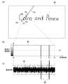
図5に示す例では、画像データG1には、描画物OB1として、ペン30による手書きの“Love and Peace”という描画が含まれている。画像データG1は、例えば、表示画面DFのサイズに対応したBMP(Bit MaP)データである。 In the example shown in FIG. 5, the image data G1 includes a handwritten drawing of "Love and Peace" with the
次に、図6を参照して、画像データを受信する側のペン30の処理について説明する。
図6は、本実施形態におけるペン30の画像データの受信処理の一例を示すフローチャートである。Next, with reference to FIG. 6, the processing of the
FIG. 6 is a flowchart illustrating an example of the image data reception process of the
図6に示すように、ペン30のペン制御部70(振動制御部71)は、画像データ又は部分画像データを受信したか否かを判定する(ステップS201)。ペン制御部70は、無線通信部31によりタブレット端末1から、画像データ又は部分画像データを受信したか否かを判定する。ペン制御部70は、画像データ又は部分画像データを受信した場合(ステップS201:YES)に、処理をステップS202に進める。また、ペン制御部70は、画像データ又は部分画像データを受信していない場合(ステップS201:NO)に、処理をステップS201に戻す。 As shown in FIG. 6, the pen control unit 70 (vibration control unit 71) of the
ステップS202において、ペン制御部70(振動制御部71)は、受信した画像データが部分画像データであるか否かを判定する。ペン制御部70は、受信した画像データが部分画像データである場合(ステップS202:YES)に、処理をステップS204に進める。また、ペン制御部70は、受信した画像データが部分画像データでない場合(ステップS202:NO)に、処理をステップS203に進める。 In step S202, the pen control unit 70 (vibration control unit 71) determines whether the received image data is partial image data. If the received image data is partial image data (step S202: YES), the
ステップS203において、ペン制御部70(振動制御部71)は、画像データを画像データ記憶部62に記憶させる。ペン制御部70は、受信した全体画像データを、画像データ記憶部62に記憶させて、画像データ(全体画像データ)を更新する。ステップS203の処理後に、ペン制御部70は、処理をステップS201に戻す。 In step S203, the pen control unit 70 (vibration control unit 71) stores the image data in the image
また、ステップS204において、ペン制御部70(振動制御部71)は、部分画像データにより画像データを更新して、画像データ記憶部62に記憶させる。ペン制御部70は、部分画像データに付与されている位置情報に基づいて、画像データ記憶部62が記憶する画像データ(全体画像データ)の一部を置き換えて、画像データ(全体画像データ)を更新し、更新した画像データ(全体画像データ)を画像データ記憶部62に記憶させる。 Further, in step S204, the pen control unit 70 (vibration control unit 71) updates the image data with the partial image data and stores it in the image
このように、ペン30では、タブレット端末1から受信した画像データ(又は部分画像データ)により、画像データ記憶部62が記憶する画像データ(全体画像データ)を定期的に更新する。 In this manner, the
次に、図7を参照して、本実施形態におけるタブレット端末1のペン入力処理について説明する。
図7は、本実施形態におけるタブレット端末1のペン入力処理の一例を示すフローチャートである。Next, with reference to FIG. 7, pen input processing of the
FIG. 7 is a flowchart showing an example of pen input processing of the
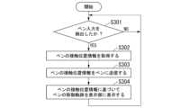
図7に示すように、タブレット端末1の入力処理部101は、ペン入力を検出したか否かを判定する(ステップS301)。入力処理部101は、タッチセンサ部22によって、ペン入力が検出されたか否かを判定する。入力処理部101は、ペン入力を検出した場合(ステップS301:YES)に、処理をステップS302に進める。また、入力処理部101は、ペン入力を検出していない場合(ステップS301:NO)に、処理をステップS301に戻す。 As shown in FIG. 7, the
ステップS302において、入力処理部101は、ペン30の接触位置情報を取得する。入力処理部101は、タッチセンサ部22から接触位置情報を取得し、ペン位置情報記憶部42に記憶させる。 In step S302, the
次に、タブレット端末1の位置送信処理部112は、ペン30の接触位置情報をペン30に送信する(ステップS303)。位置送信処理部112は、無線通信部29を介して、無線通信によりペン30の接触位置情報をペン30に送信する。 Next, the position
次に、タブレット端末1の表示処理部102は、ペン30の接触位置情報に基づいてペン30の移動軌跡を表示部21に表示する(ステップS304)。表示処理部102は、例えば、ペン位置情報記憶部42が記憶しているペン30の接触位置情報に基づいて、画面上のペン30の移動軌跡を、表示部21に表示させる。ステップS304の処理後に、表示処理部102は、処理をステップS301に戻す。 Next, the
次に、図8を参照して、本実施形態におけるペン30の振動出力処理について説明する。
図8は、本実施形態におけるペン30の振動出力処理の一例を示すフローチャートである。Next, with reference to FIG. 8, vibration output processing of the
FIG. 8 is a flowchart illustrating an example of vibration output processing of the
図8に示すように、ペン30の振動制御部71は、まず、ペン30の接触位置情報を受信したか否かを判定する(ステップS401)。振動制御部71は、無線通信部31によってペン30の接触位置情報を、タブレット端末1から受信したか否かを判定する。振動制御部71は、ペン30の接触位置情報を受信した場合(ステップS401:YES)に、処理をステップS402に進める。また、振動制御部71は、ペン30の接触位置情報を受信していない場合(ステップS401:NO)に、処理をステップS401に戻す。 As shown in FIG. 8, the
ステップS402において、振動制御部71は、ペン30の通過区間の濃淡の階調値が閾値Th1を黒側(濃側)に超えたか否かを判定する。振動制御部71は、濃淡の階調値が閾値Th1を黒側(濃側)に超えた場合(ステップS402:YES)に、処理をステップS403に進める。また、振動制御部71は、濃淡の階調値が閾値Th1を黒側(濃側)に超えていない場合(ステップS402:NO)に、処理をステップS404に進める。 In step S402, the
ステップ403において、振動制御部71は、振動波形信号に特定の波形信号を加算して、アクチュエータ34から振動を出力する。振動制御部71は、振動波形記憶部61が記憶する、指定された基本波形データに基づく振動波形信号に、振動波形記憶部61が記憶する特定の波形信号(パルス波形)を加算(重畳)して、振動生成部50によりアクチュエータ34から振動を出力させる。ステップS403の処理後に、振動制御部71は、処理をステップS401に戻す。 In step 403, the
また、ステップ404において、振動制御部71は、通常の振動波形信号により、アクチュエータ34から振動を出力する。振動制御部71は、振動波形記憶部61が記憶する、指定された基本波形データに基づく通常の振動波形信号を、振動生成部50によりアクチュエータ34から振動を出力させる。ステップS404の処理後に、振動制御部71は、処理をステップS401に戻す。 Further, in step 404, the
次に、図9を参照して、本実施形態による情報処理システム100の振動出力処理の具体例について説明する。
図9は、本実施形態による情報処理システム100の振動出力処理の一例を説明する図である。Next, a specific example of vibration output processing of the
FIG. 9 is a diagram illustrating an example of vibration output processing of the
図9(a)は、表示画面DFに、上述した図5に示す画像データG1を表示している状態において、ペン30を画面に接触させて位置P0から位置P3に移動させた場合の一例を示している。 FIG. 9A shows an example of the case where the
また、図9(b)では、ペン30を位置P0から位置P3に移動させた場合の通過区間における濃淡の階調値の変化を示している。図9(b)において、グラフは、縦軸が、濃淡の階調値を示し、横軸が移動距離を示している。また、波形W1は、濃淡の階調値の変化を示している。 Further, FIG. 9B shows changes in the gradation values of shading in the passing section when the
また、図9(c)では、ペン30がアクチュエータ34に出力させる振動波形を示している。図9(c)において、波形W2は、通常の振動波形を示し、波形W3は、追加する特定の振動波形(パルス波形)を示している。 Further, FIG. 9(c) shows a vibration waveform outputted by the
図9に示す例では、画像データG1の描画物OB1である“Love”の手書き描画の“o”(オー)の上に、ペン30を通過させて、インク線LN1を引いた場合の一例を示している。ここで、インク線LN1の位置P0から位置P3の間で、“o”の描画線を、位置P1及び位置P2において、交差(クロス)する。 In the example shown in FIG. 9, an example is shown in which an ink line LN1 is drawn by passing the
この場合、濃淡の階調値の変化は、図9(b)の波形W1に示すように、位置P0から白色の階調値が継続されて、位置P1において、黒色の階調値に変化する。また、位置P1を通過後に、再び白色の階調値が継続されて、位置P2において、黒色の階調値に変化する。また、位置P1を通過後に、再び白色の階調値が継続される。 In this case, as shown in the waveform W1 of FIG. 9(b), the change in the gradation value is such that the gradation value of white continues from position P0 and changes to the gradation value of black at position P1. . Further, after passing through position P1, the white gradation value continues again, and changes to the black gradation value at position P2. Furthermore, after passing the position P1, the white gradation value continues again.
また、この場合、振動制御部71は、図9(c)の波形W2に示すように、位置P0から位置P1の間の期間、位置P1から位置P2の間の期間、及び位置P2から位置P3の間の期間において、波形W2の振動波形を、アクチュエータ34に出力させる。また、振動制御部71は、位置P1及び位置P2において、波形W1に示すように、階調値が、閾値Th1を黒側に超えるため、波形W2に波形W3の特定の振動波形(パルス波形)を加算した波形を、アクチュエータ34に出力させる。 Further, in this case, the
以上説明したように、本実施形態による情報処理システム100は、タブレット端末1(情報処理装置)と、タブレット端末1と通信可能なペン30とを備える。タブレット端末1は、表示部21と、タッチセンサ部22と、表示処理部102と、画像送信処理部111と、位置送信処理部112とを備える。表示部21は、ペン30の移動軌跡(描画軌跡)を表示可能である。タッチセンサ部22は、表示部21の画面上におけるペン30の接触位置を検出する。表示処理部102は、タッチセンサ部22が検出したペン30の接触位置に基づいて、ペン30が画面上に接触して移動した画面上の移動軌跡を、表示部21に表示させる。画像送信処理部111は、移動軌跡を含む表示部21が表示する画像データをペン30に送信する。位置送信処理部112は、タッチセンサ部22が検出したペン30の接触位置を、ペン30に送信する。また、ペン30は、アクチュエータ34(振動発生器)と、振動制御部71とを備える。アクチュエータ34は、振動波形信号に基づいて、振動を出力する。振動制御部71は、画像データの移動軌跡を含む描画物(例えば、図5に示す描画物OB1など)と、ペン30の接触位置とが一致した場合に、振動波形信号に特定の波形信号を加算して、アクチュエータ34に振動を出力させる。 As described above, the
これにより、本実施形態による情報処理システム100は、画像データの描画物と、ペン30の接触位置とが一致した場合に、振動波形信号に特定の波形信号を加算して、アクチュエータ34に振動を出力させるため、例えば、ペン30が描画軌跡をクロスする際に、適切な振動を出力することができる。よって、本実施形態による情報処理システム100は、ペン30が描画軌跡をクロスする際のペン入力の感触の違和感を低減することができる。 As a result, the
なお、本実施形態による情報処理システム100では、ペン30側の振動制御部71が、ペン30が描画軌跡をクロスするタイミングを判定して、振動波形信号に特定の波形信号を加算して、アクチュエータ34に振動を出力させる。例えば、タブレット端末1側で、ペン30が描画軌跡をクロスするタイミングを判定した場合には、タブレット端末1側で、ペン30が描画軌跡をクロスするタイミングを判定した後に、振動波形信号を切り替える指示を、ペン30に送信する必要がある。そのため、タブレット端末1側で、ペン30が描画軌跡をクロスするタイミングを判定した場合には、振動波形信号を切り替えるまでに遅延(タイムラグ)が発生して、ペン30が描画軌跡をクロスするタイミングに、振動波形信号を切り替えることは困難である。 In the
これに対して、本実施形態による情報処理システム100では、ペン30側の振動制御部71が、ペン30が描画軌跡をクロスするタイミングを判定するため、振動波形信号を切り替えるまでの遅延(タイムラグ)を低減することができ、違和感を低減した振動をペン30に発生することができる。 In contrast, in the
また、本実施形態では、画像送信処理部111は、グレイスケールに変換した画像データを、ペン30に送信する。振動制御部71は、画像データにおいて、ペン30の移動による通過区間の濃淡の階調値が閾値Th1を黒側に超えた場合に、振動波形信号(例えば、図9の波形W2)に特定の波形信号(例えば、図9の波形W3)を加算して、アクチュエータ34に振動を出力させる(図9参照)。 Further, in this embodiment, the image
これにより、本実施形態による情報処理システム100は、濃淡の階調値が閾値Th1を黒側に超えたことを判定することにより、描画物(例えば、図5に示す描画物OB1など)と、ペン30の接触位置とが一致したこと(ペン30が描画軌跡をクロスしたこと)を、簡単且つ適切に判定することができる。 As a result, the
また、本実施形態では、画像送信処理部111は、定期的に、画像データ(全体画像データ)をペン30に送信して、画像データ(全体画像データ)を更新する。
これにより、本実施形態による情報処理システム100は、定期的に、画像データ(全体画像データ)をペン30に送信して、画像データ(全体画像データ)を更新することで、例えば、ペン30が描画軌跡をクロスするタイミングをさらに適切に判定することができる。Further, in this embodiment, the image
As a result, the
また、本実施形態では、画像送信処理部111は、定期的に、ペン30の接触位置の周辺を含む部分画像データをペン30に送信して、画像データ(全体画像データ)を更新する。すなわち、画像送信処理部111は、表示部21の表示画面DFにペン30が接触している場合に、ペン30の接触位置の周辺を含む部分画像データをペン30に送信して、画像データ(全体画像データ)を更新する。 Further, in the present embodiment, the image
これにより、本実施形態による情報処理システム100は、定期的に、ペン30の接触位置の周辺を含む部分画像データをペン30に送信することで、画像データ(全体画像データ)を更新する処理負荷及び通信負荷を低減することができる。 As a result, the
なお、本実施形態による情報処理システム100では、ペン30の接触位置の周辺を含む部分画像データをペン30に送信することで、例えば、ペン30の描画線の太さが異なる場合などのように、ペン30の種類が複数ある場合やスタンプなどを描画する場合などにおいて、画像データの更新をより適切に行うことができ、ペン入力の感触の違和感をより適切に低減することができる。 In addition, in the
また、本実施形態では、ペン30は、画像データを記憶する画像データ記憶部62を備える。画像送信処理部111は、画像データをペン30に送信して、画像データ記憶部62に記憶させる。振動制御部71は、画像データ記憶部62から取得した画像データの描画物と、ペン30の接触位置とが一致した場合に、振動波形信号に特定の波形信号を加算して、アクチュエータ34に振動を出力させる。 Furthermore, in this embodiment, the
これにより、本実施形態による情報処理システム100は、画像データ記憶部62を備えることにより、ペン30に画像データを適切に保存することができるとともに、画像データの更新をより適切に行うことができ、ペン入力の感触の違和感をより適切に低減することができる。 Accordingly, by including the image
また、本実施形態では、タブレット端末1が、無線通信部29(第1無線通信部)を備え、ペン30は、無線通信部31(第2無線通信部)を備える。画像送信処理部111及び位置送信処理部112は、無線通信部29(第1無線通信部)と無線通信部31(第2無線通信部)との間の無線通信により、画像データ及び接触位置情報を、タブレット端末1からペン30に送信する。 Furthermore, in this embodiment, the
これにより、本実施形態による情報処理システム100は、無線通信により、画像データ及び接触位置情報を、タブレット端末1からペン30に送信するため、ペン30を有線によりタブレット端末1と接続する必要がない。そのため、本実施形態による情報処理システム100は、ペン30の操作の自由度を高めることができ、ペン30の使い勝手を向上させることができる。 Thereby, the
また、本実施形態による制御方法は、ペン30の移動軌跡を表示可能な表示部21と、表示部21の画面上におけるペン30の接触位置を検出するタッチセンサ部22とを有するタブレット端末1と、タブレット端末1と通信可能であり、振動波形信号に基づいて、振動を出力するアクチュエータ34を有するペン30とを備える情報処理システム100の制御方法であって、表示処理ステップと、画像送信処理ステップと、位置送信処理ステップと、振動制御ステップとを含む。表示処理ステップにおいて、タブレット端末1が、タッチセンサ部22が検出したペン30の接触位置に基づいて、ペン30が画面上に接触して移動した画面上の移動軌跡を、表示部21に表示させる。画像送信処理ステップにおいて、タブレット端末1が、移動軌跡を含む表示部21が表示する画像データをペン30に送信する。位置送信処理ステップにおいて、タブレット端末1が、タッチセンサ部22が検出したペン30の接触位置を、ペン30に送信する。振動制御ステップにおいて、ペン30が、画像データの移動軌跡を含む描画物と、ペン30の接触位置とが一致した場合に、振動波形信号に特定の波形信号を加算して、アクチュエータ34に振動を出力させる。 The control method according to the present embodiment also applies to a
これにより、本実施形態による制御方法は、上述した情報処理システム100と同様の効果を奏し、ペン30が描画軌跡をクロスする際のペン入力の感触の違和感を低減することができる。 As a result, the control method according to the present embodiment has the same effect as the
なお、本発明は、上記の実施形態に限定されるものではなく、本発明の趣旨を逸脱しない範囲で変更可能である。
例えば、上記の実施形態において、情報処理装置が、タブレット端末1である例を説明したが、これに限定されるものではない。情報処理装置は、例えば、スマートフォンやタブレットモードを備えるノートブック型パーソナルコンピュータなどであってもよい。Note that the present invention is not limited to the above-described embodiments, and can be modified without departing from the spirit of the present invention.
For example, in the above embodiment, an example in which the information processing device is the
また、上記の各実施形態において、使用するOSの一例として、Android(登録商標)を用いる例を説明したが、これに限定されるものではなく、例えば、iOS(登録商標)などの他のOSに適用してもよい。 In addition, in each of the above embodiments, an example of using Android (registered trademark) has been described as an example of the OS used, but the invention is not limited to this. For example, other OS such as iOS (registered trademark) May be applied to
また、上記の各実施形態において、振動発生器が、アクチュエータ34である例を説明したが、これに限定されるものではなく、例えば、音を出力するスピーカなどの他の機器であってもよい。また、振動発生器として、アクチュエータ34とスピーカとを組み合わせて使用してもよい。 Further, in each of the above embodiments, an example has been described in which the vibration generator is the
また、上記の各実施形態において、無線通信部29及び無線通信部31は、無線通信として、Bluetooth(登録商標)を用いる例を説明したが、これに限定されるものではなく、他の方式の無線通信を用いてもよい。また、タブレット端末1とペン30との間の通信は、無線通信の代わりに、有線通信を用いてもよい。 Further, in each of the above embodiments, the
また、上記の各実施形態において、振動制御部71は、濃淡の階調値が閾値Th1を黒側に超えた場合に、特定の波形信号(パルス波形)を加算(重畳)する例を説明したが、これに限定されるものではなく、例えば、色の変化量に応じたレベルの特定の波形信号(パルス波形)を加算又は発生させるようにしてもよい。 Furthermore, in each of the above embodiments, an example has been described in which the
なお、上述した情報処理システム100が備える各構成は、内部に、コンピュータシステムを有している。そして、上述した情報処理システム100が備える各構成の機能を実現するためのプログラムをコンピュータ読み取り可能な記録媒体に記録して、この記録媒体に記録されたプログラムをコンピュータシステムに読み込ませ、実行することにより上述した情報処理システム100が備える各構成における処理を行ってもよい。ここで、「記録媒体に記録されたプログラムをコンピュータシステムに読み込ませ、実行する」とは、コンピュータシステムにプログラムをインストールすることを含む。ここでいう「コンピュータシステム」とは、OSや周辺機器等のハードウェアを含むものとする。 Note that each component included in the
また、「コンピュータシステム」は、インターネットやWAN、LAN、専用回線等の通信回線を含むネットワークを介して接続された複数のコンピュータ装置を含んでもよい。また、「コンピュータ読み取り可能な記録媒体」とは、フレキシブルディスク、光磁気ディスク、ROM、CD-ROM等の可搬媒体、コンピュータシステムに内蔵されるハードディスク等の記憶装置のことをいう。このように、プログラムを記憶した記録媒体は、CD-ROM等の非一過性の記録媒体であってもよい。 Further, a "computer system" may include a plurality of computer devices connected via a network including the Internet, a WAN, a LAN, a communication line such as a dedicated line, etc. Furthermore, the term "computer-readable recording medium" refers to portable media such as flexible disks, magneto-optical disks, ROMs, and CD-ROMs, and storage devices such as hard disks built into computer systems. In this way, the recording medium storing the program may be a non-transitory recording medium such as a CD-ROM.
また、記録媒体には、当該プログラムを配信するために配信サーバからアクセス可能な内部又は外部に設けられた記録媒体も含まれる。なお、プログラムを複数に分割し、それぞれ異なるタイミングでダウンロードした後に情報処理システム100が備える各構成で合体される構成や、分割されたプログラムのそれぞれを配信する配信サーバが異なっていてもよい。さらに「コンピュータ読み取り可能な記録媒体」とは、ネットワークを介してプログラムが送信された場合のサーバやクライアントとなるコンピュータシステム内部の揮発性メモリ(RAM)のように、一定時間プログラムを保持しているものも含むものとする。また、上記プログラムは、上述した機能の一部を実現するためのものであってもよい。さらに、上述した機能をコンピュータシステムに既に記録されているプログラムとの組み合わせで実現できるもの、いわゆる差分ファイル(差分プログラム)であってもよい。 The recording medium also includes a recording medium provided internally or externally that can be accessed from the distribution server for distributing the program. Note that the program may be divided into a plurality of programs, downloaded at different timings, and then combined into each component of the
また、上述した機能の一部又は全部を、LSI(Large Scale Integration)等の集積回路として実現してもよい。上述した各機能は個別にプロセッサ化してもよいし、一部、又は全部を集積してプロセッサ化してもよい。また、集積回路化の手法はLSIに限らず専用回路、又は汎用プロセッサで実現してもよい。また、半導体技術の進歩によりLSIに代替する集積回路化の技術が出現した場合、当該技術による集積回路を用いてもよい。 Further, some or all of the functions described above may be realized as an integrated circuit such as an LSI (Large Scale Integration). Each of the above-mentioned functions may be implemented as an individual processor, or some or all of them may be integrated into a processor. Moreover, the method of circuit integration is not limited to LSI, but may be implemented using a dedicated circuit or a general-purpose processor. Further, if an integrated circuit technology that replaces LSI emerges due to advances in semiconductor technology, an integrated circuit based on this technology may be used.
1 タブレット端末
10 制御部
11 プロセッサ
12 メインメモリ
13 フラッシュメモリ
20 タッチスクリーン
21 表示部
22 タッチセンサ部
23 周辺デバイス
24 オーディオシステム
25 マイク
26 スピーカ
27 ベースバンドチップ
28 無線部
29、31 無線通信部
30 ペン
32 DAC
33 アンプ
34 アクチュエータ
35 メモリ
36 MCU
40 記憶部
41、62 画像データ記憶部
42 ペン位置情報記憶部
50 振動生成部
60 ペン記憶部
61 振動波形記憶部
70 ペン制御部
71 振動制御部
100 情報処理システム
101 入力処理部
102 表示処理部
110 ペン振動制御部
111 画像送信処理部
112 位置送信処理部1
33
40
Claims (6)
Translated fromJapanese前記情報処理装置は、
前記ペンの移動軌跡を表示可能な表示部と、
前記表示部の画面上における前記ペンの接触位置を検出するタッチセンサ部と、
前記タッチセンサ部が検出した前記ペンの接触位置に基づいて、前記ペンが前記画面上に接触して移動した前記画面上の移動軌跡を、前記表示部に表示させる表示処理部と、
前記移動軌跡を含む前記表示部が表示する画像データを前記ペンに送信する画像送信処理部と、
前記タッチセンサ部が検出した前記ペンの接触位置を、前記ペンに送信する位置送信処理部と
を備え、
前記ペンは、
振動波形信号に基づいて、振動を出力する振動発生器と、
前記画像データの前記移動軌跡を含む描画物と、前記ペンの接触位置とが一致した場合に、前記振動波形信号に特定の波形信号を加算して、前記振動発生器に振動を出力させる振動制御部と
を備える情報処理システム。An information processing system comprising an information processing device and a pen capable of communicating with the information processing device,
The information processing device includes:
a display unit capable of displaying a movement trajectory of the pen;
a touch sensor unit that detects a contact position of the pen on the screen of the display unit;
a display processing unit that causes the display unit to display a movement trajectory on the screen in which the pen touched and moved on the screen, based on a contact position of the pen detected by the touch sensor unit;
an image transmission processing unit that transmits image data displayed by the display unit including the movement trajectory to the pen;
a position transmission processing unit that transmits a contact position of the pen detected by the touch sensor unit to the pen,
The pen is
a vibration generator that outputs vibration based on the vibration waveform signal;
Vibration control that adds a specific waveform signal to the vibration waveform signal and causes the vibration generator to output vibration when the drawn object including the movement trajectory of the image data matches the contact position of the pen. An information processing system comprising a department and a department.
前記振動制御部は、前記画像データにおいて、前記ペンの移動による通過区間の濃淡の階調値が閾値を黒側に超えた場合に、前記振動波形信号に前記特定の波形信号を加算して、前記振動発生器に振動を出力させる
請求項1に記載の情報処理システム。The image transmission processing unit transmits the image data converted to gray scale to the pen,
The vibration control unit adds the specific waveform signal to the vibration waveform signal when a gray scale value of a passing section due to the movement of the pen exceeds a threshold toward black in the image data; The information processing system according to claim 1, wherein the vibration generator is caused to output vibration.
請求項1に記載の情報処理システム。The information processing system according to claim 1, wherein the image transmission processing unit periodically transmits the image data to the pen to update the image data.
請求項1に記載の情報処理システム。The information processing system according to claim 1, wherein the image transmission processing unit periodically transmits partial image data including the vicinity of a contact position of the pen to the pen to update the image data.
前記画像送信処理部は、前記画像データを前記ペンに送信して、前記画像データ記憶部に記憶させ、
前記振動制御部は、前記画像データ記憶部から取得した前記画像データの前記描画物と、前記ペンの接触位置とが一致した場合に、前記振動波形信号に特定の波形信号を加算して、前記振動発生器に振動を出力させる
請求項1から請求項4のいずれか一項に記載の情報処理システム。The pen includes an image data storage unit that stores the image data,
The image transmission processing unit transmits the image data to the pen and stores it in the image data storage unit,
The vibration control unit is configured to add a specific waveform signal to the vibration waveform signal when the drawn object of the image data acquired from the image data storage unit matches the contact position of the pen. The information processing system according to any one of claims 1 to 4, wherein the vibration generator is caused to output vibration.
前記情報処理装置が、前記タッチセンサ部が検出した前記ペンの接触位置に基づいて、前記ペンが前記画面上に接触して移動した前記画面上の移動軌跡を、前記表示部に表示させる表示処理ステップと、
前記情報処理装置が、前記移動軌跡を含む前記表示部が表示する画像データを前記ペンに送信する画像送信処理ステップと、
前記情報処理装置が、前記タッチセンサ部が検出した前記ペンの接触位置を、前記ペンに送信する位置送信処理ステップと、
前記ペンが、前記画像データの前記移動軌跡を含む描画物と、前記ペンの接触位置とが一致した場合に、前記振動波形信号に特定の波形信号を加算して、前記振動発生器に振動を出力させる振動制御ステップと
を含む制御方法。an information processing device that is capable of communicating with the information processing device, has a display unit that can display a movement trajectory of a pen, and a touch sensor unit that detects a contact position of the pen on the screen of the display unit; A method for controlling an information processing system, comprising: a pen having a vibration generator that outputs vibrations based on a signal;
Display processing in which the information processing device causes the display unit to display a movement trajectory on the screen in which the pen touched and moved on the screen, based on the contact position of the pen detected by the touch sensor unit. step and
an image transmission processing step in which the information processing device transmits image data displayed by the display unit including the movement trajectory to the pen;
a position transmission processing step in which the information processing device transmits a contact position of the pen detected by the touch sensor unit to the pen;
When the drawing object including the movement trajectory of the image data and the contact position of the pen match, a specific waveform signal is added to the vibration waveform signal to cause the vibration generator to vibrate. A control method including a vibration control step for outputting.
Priority Applications (4)
| Application Number | Priority Date | Filing Date | Title |
|---|---|---|---|
| JP2023000173AJP7393568B1 (en) | 2023-01-04 | 2023-01-04 | Information processing system and control method |
| EP23210519.7AEP4398077A1 (en) | 2023-01-04 | 2023-11-17 | Information processing system and control method |
| US18/544,979US12242680B2 (en) | 2023-01-04 | 2023-12-19 | Information processing system and control method |
| CN202410005504.6ACN118295518A (en) | 2023-01-04 | 2024-01-03 | Information processing system and control method |
Applications Claiming Priority (1)
| Application Number | Priority Date | Filing Date | Title |
|---|---|---|---|
| JP2023000173AJP7393568B1 (en) | 2023-01-04 | 2023-01-04 | Information processing system and control method |
Publications (2)
| Publication Number | Publication Date |
|---|---|
| JP7393568B1true JP7393568B1 (en) | 2023-12-06 |
| JP2024096593A JP2024096593A (en) | 2024-07-17 |
Family
ID=88839246
Family Applications (1)
| Application Number | Title | Priority Date | Filing Date |
|---|---|---|---|
| JP2023000173AActiveJP7393568B1 (en) | 2023-01-04 | 2023-01-04 | Information processing system and control method |
Country Status (4)
| Country | Link |
|---|---|
| US (1) | US12242680B2 (en) |
| EP (1) | EP4398077A1 (en) |
| JP (1) | JP7393568B1 (en) |
| CN (1) | CN118295518A (en) |
Families Citing this family (1)
| Publication number | Priority date | Publication date | Assignee | Title |
|---|---|---|---|---|
| CN117075735A (en)* | 2023-08-31 | 2023-11-17 | 联想(北京)有限公司 | A control method, first electronic device and storage medium |
Citations (5)
| Publication number | Priority date | Publication date | Assignee | Title |
|---|---|---|---|---|
| US20090135164A1 (en) | 2007-11-26 | 2009-05-28 | Ki Uk Kyung | Pointing apparatus capable of providing haptic feedback, and haptic interaction system and method using the same |
| US20180081456A1 (en) | 2016-09-19 | 2018-03-22 | Apple Inc. | Multipurpose stylus with exchangeable modules |
| JP2018185823A (en) | 2012-11-20 | 2018-11-22 | イマージョン コーポレーションImmersion Corporation | System and method for providing mode or state recognition with programmable surface texture |
| JP2019169166A (en) | 2009-03-12 | 2019-10-03 | イマージョン コーポレーションImmersion Corporation | Systems and methods for interfaces featuring surface-based haptic effects |
| WO2023157556A1 (en) | 2022-02-21 | 2023-08-24 | 株式会社ワコム | System including pen and pen position detection device, pen position detection device, and method for operating haptic element built into pen |
Family Cites Families (3)
| Publication number | Priority date | Publication date | Assignee | Title |
|---|---|---|---|---|
| JP2015114836A (en)* | 2013-12-11 | 2015-06-22 | キヤノン株式会社 | Image processing apparatus, tactile sensation control method, and program |
| US10042439B2 (en) | 2014-12-11 | 2018-08-07 | Microsft Technology Licensing, LLC | Interactive stylus and display device |
| US11797090B2 (en)* | 2021-05-13 | 2023-10-24 | Microsoft Technology Licensing, Llc | Stylus haptic output |
- 2023
- 2023-01-04JPJP2023000173Apatent/JP7393568B1/enactiveActive
- 2023-11-17EPEP23210519.7Apatent/EP4398077A1/enactivePending
- 2023-12-19USUS18/544,979patent/US12242680B2/enactiveActive
- 2024
- 2024-01-03CNCN202410005504.6Apatent/CN118295518A/enactivePending
Patent Citations (5)
| Publication number | Priority date | Publication date | Assignee | Title |
|---|---|---|---|---|
| US20090135164A1 (en) | 2007-11-26 | 2009-05-28 | Ki Uk Kyung | Pointing apparatus capable of providing haptic feedback, and haptic interaction system and method using the same |
| JP2019169166A (en) | 2009-03-12 | 2019-10-03 | イマージョン コーポレーションImmersion Corporation | Systems and methods for interfaces featuring surface-based haptic effects |
| JP2018185823A (en) | 2012-11-20 | 2018-11-22 | イマージョン コーポレーションImmersion Corporation | System and method for providing mode or state recognition with programmable surface texture |
| US20180081456A1 (en) | 2016-09-19 | 2018-03-22 | Apple Inc. | Multipurpose stylus with exchangeable modules |
| WO2023157556A1 (en) | 2022-02-21 | 2023-08-24 | 株式会社ワコム | System including pen and pen position detection device, pen position detection device, and method for operating haptic element built into pen |
Also Published As
| Publication number | Publication date |
|---|---|
| EP4398077A1 (en) | 2024-07-10 |
| US20240220039A1 (en) | 2024-07-04 |
| CN118295518A (en) | 2024-07-05 |
| JP2024096593A (en) | 2024-07-17 |
| US12242680B2 (en) | 2025-03-04 |
Similar Documents
| Publication | Publication Date | Title |
|---|---|---|
| KR102374710B1 (en) | Method and electronic device for driving a display at low power | |
| CN104007816B (en) | The mobile terminal of method and realization this method for providing voice-speech service | |
| CN103761044B (en) | Touch event model programming interface | |
| US9542727B2 (en) | Reproducing device, setting changing method, and setting changing device | |
| KR102389185B1 (en) | Electronic device and method for executing function using input interface displayed via at least portion of content | |
| CN107801113B (en) | A kind of method, wireless headset and mobile terminal controlling wireless headset sound channel | |
| CN103677711A (en) | Method for connecting mobile terminal and external display and device for realizing the method | |
| CN110855551B (en) | Message reply method, server and electronic equipment | |
| JP7393568B1 (en) | Information processing system and control method | |
| JP7293462B1 (en) | Information processing system, information processing device, and control method | |
| WO2017173576A1 (en) | Display method and terminal | |
| US11169769B2 (en) | Electronic device and volume adjustment method of electronic device | |
| US11449176B2 (en) | Information processing system and method for avoiding execution of unintentional drawing operations | |
| JP2023104111A (en) | Information processing apparatus and control method | |
| JP2015516611A (en) | Display spatially related annotations for written content | |
| CN111190528B (en) | Brush display method, electronic equipment and storage medium | |
| JP7728934B1 (en) | Information processing system and control method | |
| JP7605937B1 (en) | Input device and information processing system | |
| US20230289014A1 (en) | Information processing apparatus and controlling method | |
| JP7627801B1 (en) | Information processing system, information processing method, and program | |
| CN111090393A (en) | Stored data processing method, stored data processing device and electronic device | |
| JP7487385B1 (en) | Information processing system, pen-type input device, and program | |
| CN110099169A (en) | Instant message processing method, electronic device and computer readable storage medium | |
| CN109189311A (en) | Sounding control method, device, electronic equipment and storage medium | |
| JP7562753B1 (en) | Information processing device and control method |
Legal Events
| Date | Code | Title | Description |
|---|---|---|---|
| A621 | Written request for application examination | Free format text:JAPANESE INTERMEDIATE CODE: A621 Effective date:20230104 | |
| A711 | Notification of change in applicant | Free format text:JAPANESE INTERMEDIATE CODE: A711 Effective date:20230322 | |
| TRDD | Decision of grant or rejection written | ||
| A01 | Written decision to grant a patent or to grant a registration (utility model) | Free format text:JAPANESE INTERMEDIATE CODE: A01 Effective date:20231114 | |
| A61 | First payment of annual fees (during grant procedure) | Free format text:JAPANESE INTERMEDIATE CODE: A61 Effective date:20231124 | |
| R150 | Certificate of patent or registration of utility model | Ref document number:7393568 Country of ref document:JP Free format text:JAPANESE INTERMEDIATE CODE: R150 | |
| S111 | Request for change of ownership or part of ownership | Free format text:JAPANESE INTERMEDIATE CODE: R313113 | |
| R350 | Written notification of registration of transfer | Free format text:JAPANESE INTERMEDIATE CODE: R350 | |
| S111 | Request for change of ownership or part of ownership | Free format text:JAPANESE INTERMEDIATE CODE: R313113 | |
| R350 | Written notification of registration of transfer | Free format text:JAPANESE INTERMEDIATE CODE: R350 |