JP7387407B2 - connector assembly - Google Patents
connector assemblyDownload PDFInfo
- Publication number
- JP7387407B2 JP7387407B2JP2019213901AJP2019213901AJP7387407B2JP 7387407 B2JP7387407 B2JP 7387407B2JP 2019213901 AJP2019213901 AJP 2019213901AJP 2019213901 AJP2019213901 AJP 2019213901AJP 7387407 B2JP7387407 B2JP 7387407B2
- Authority
- JP
- Japan
- Prior art keywords
- connector
- engagement
- shell
- fitting
- orthogonal
- Prior art date
- Legal status (The legal status is an assumption and is not a legal conclusion. Google has not performed a legal analysis and makes no representation as to the accuracy of the status listed.)
- Active
Links
- 239000000758substrateSubstances0.000claimsdescription14
- 239000002184metalSubstances0.000claimsdescription11
- 230000000712assemblyEffects0.000claimsdescription7
- 238000000429assemblyMethods0.000claimsdescription7
- 208000032365Electromagnetic interferenceDiseases0.000description11
- 239000004020conductorSubstances0.000description6
- 239000012212insulatorSubstances0.000description5
- 210000000078clawAnatomy0.000description3
- 230000013011matingEffects0.000description3
- 238000000034methodMethods0.000description3
- 230000001681protective effectEffects0.000description3
- 238000005476solderingMethods0.000description3
- 230000015572biosynthetic processEffects0.000description2
- 239000000463materialSubstances0.000description2
- 238000012986modificationMethods0.000description2
- 230000004048modificationEffects0.000description2
- 238000013459approachMethods0.000description1
- 238000005452bendingMethods0.000description1
- 238000002788crimpingMethods0.000description1
- 238000000465mouldingMethods0.000description1
- 238000003466weldingMethods0.000description1
Images


Classifications
- H—ELECTRICITY
- H01—ELECTRIC ELEMENTS
- H01R—ELECTRICALLY-CONDUCTIVE CONNECTIONS; STRUCTURAL ASSOCIATIONS OF A PLURALITY OF MUTUALLY-INSULATED ELECTRICAL CONNECTING ELEMENTS; COUPLING DEVICES; CURRENT COLLECTORS
- H01R13/00—Details of coupling devices of the kinds covered by groups H01R12/70 or H01R24/00 - H01R33/00
- H01R13/62—Means for facilitating engagement or disengagement of coupling parts or for holding them in engagement
- H01R13/627—Snap or like fastening
- H01R13/6271—Latching means integral with the housing
- H01R13/6272—Latching means integral with the housing comprising a single latching arm
- H—ELECTRICITY
- H01—ELECTRIC ELEMENTS
- H01R—ELECTRICALLY-CONDUCTIVE CONNECTIONS; STRUCTURAL ASSOCIATIONS OF A PLURALITY OF MUTUALLY-INSULATED ELECTRICAL CONNECTING ELEMENTS; COUPLING DEVICES; CURRENT COLLECTORS
- H01R13/00—Details of coupling devices of the kinds covered by groups H01R12/70 or H01R24/00 - H01R33/00
- H01R13/62—Means for facilitating engagement or disengagement of coupling parts or for holding them in engagement
- H01R13/627—Snap or like fastening
- H01R13/6271—Latching means integral with the housing
- H—ELECTRICITY
- H01—ELECTRIC ELEMENTS
- H01R—ELECTRICALLY-CONDUCTIVE CONNECTIONS; STRUCTURAL ASSOCIATIONS OF A PLURALITY OF MUTUALLY-INSULATED ELECTRICAL CONNECTING ELEMENTS; COUPLING DEVICES; CURRENT COLLECTORS
- H01R12/00—Structural associations of a plurality of mutually-insulated electrical connecting elements, specially adapted for printed circuits, e.g. printed circuit boards [PCB], flat or ribbon cables, or like generally planar structures, e.g. terminal strips, terminal blocks; Coupling devices specially adapted for printed circuits, flat or ribbon cables, or like generally planar structures; Terminals specially adapted for contact with, or insertion into, printed circuits, flat or ribbon cables, or like generally planar structures
- H01R12/70—Coupling devices
- H01R12/71—Coupling devices for rigid printing circuits or like structures
- H01R12/712—Coupling devices for rigid printing circuits or like structures co-operating with the surface of the printed circuit or with a coupling device exclusively provided on the surface of the printed circuit
- H01R12/716—Coupling device provided on the PCB
- H—ELECTRICITY
- H01—ELECTRIC ELEMENTS
- H01R—ELECTRICALLY-CONDUCTIVE CONNECTIONS; STRUCTURAL ASSOCIATIONS OF A PLURALITY OF MUTUALLY-INSULATED ELECTRICAL CONNECTING ELEMENTS; COUPLING DEVICES; CURRENT COLLECTORS
- H01R12/00—Structural associations of a plurality of mutually-insulated electrical connecting elements, specially adapted for printed circuits, e.g. printed circuit boards [PCB], flat or ribbon cables, or like generally planar structures, e.g. terminal strips, terminal blocks; Coupling devices specially adapted for printed circuits, flat or ribbon cables, or like generally planar structures; Terminals specially adapted for contact with, or insertion into, printed circuits, flat or ribbon cables, or like generally planar structures
- H01R12/70—Coupling devices
- H01R12/71—Coupling devices for rigid printing circuits or like structures
- H01R12/75—Coupling devices for rigid printing circuits or like structures connecting to cables except for flat or ribbon cables
- H—ELECTRICITY
- H01—ELECTRIC ELEMENTS
- H01R—ELECTRICALLY-CONDUCTIVE CONNECTIONS; STRUCTURAL ASSOCIATIONS OF A PLURALITY OF MUTUALLY-INSULATED ELECTRICAL CONNECTING ELEMENTS; COUPLING DEVICES; CURRENT COLLECTORS
- H01R13/00—Details of coupling devices of the kinds covered by groups H01R12/70 or H01R24/00 - H01R33/00
- H01R13/648—Protective earth or shield arrangements on coupling devices, e.g. anti-static shielding
- H01R13/658—High frequency shielding arrangements, e.g. against EMI [Electro-Magnetic Interference] or EMP [Electro-Magnetic Pulse]
- H01R13/6581—Shield structure
- H01R13/6582—Shield structure with resilient means for engaging mating connector
- H01R13/6583—Shield structure with resilient means for engaging mating connector with separate conductive resilient members between mating shield members
- H—ELECTRICITY
- H01—ELECTRIC ELEMENTS
- H01R—ELECTRICALLY-CONDUCTIVE CONNECTIONS; STRUCTURAL ASSOCIATIONS OF A PLURALITY OF MUTUALLY-INSULATED ELECTRICAL CONNECTING ELEMENTS; COUPLING DEVICES; CURRENT COLLECTORS
- H01R13/00—Details of coupling devices of the kinds covered by groups H01R12/70 or H01R24/00 - H01R33/00
- H01R13/648—Protective earth or shield arrangements on coupling devices, e.g. anti-static shielding
- H01R13/658—High frequency shielding arrangements, e.g. against EMI [Electro-Magnetic Interference] or EMP [Electro-Magnetic Pulse]
- H01R13/6591—Specific features or arrangements of connection of shield to conductive members
- H01R13/6594—Specific features or arrangements of connection of shield to conductive members the shield being mounted on a PCB and connected to conductive members
- H—ELECTRICITY
- H01—ELECTRIC ELEMENTS
- H01R—ELECTRICALLY-CONDUCTIVE CONNECTIONS; STRUCTURAL ASSOCIATIONS OF A PLURALITY OF MUTUALLY-INSULATED ELECTRICAL CONNECTING ELEMENTS; COUPLING DEVICES; CURRENT COLLECTORS
- H01R24/00—Two-part coupling devices, or either of their cooperating parts, characterised by their overall structure
- H01R24/005—Two-part coupling devices, or either of their cooperating parts, characterised by their overall structure requiring successive relative motions to complete the coupling, e.g. bayonet type
- H—ELECTRICITY
- H01—ELECTRIC ELEMENTS
- H01R—ELECTRICALLY-CONDUCTIVE CONNECTIONS; STRUCTURAL ASSOCIATIONS OF A PLURALITY OF MUTUALLY-INSULATED ELECTRICAL CONNECTING ELEMENTS; COUPLING DEVICES; CURRENT COLLECTORS
- H01R12/00—Structural associations of a plurality of mutually-insulated electrical connecting elements, specially adapted for printed circuits, e.g. printed circuit boards [PCB], flat or ribbon cables, or like generally planar structures, e.g. terminal strips, terminal blocks; Coupling devices specially adapted for printed circuits, flat or ribbon cables, or like generally planar structures; Terminals specially adapted for contact with, or insertion into, printed circuits, flat or ribbon cables, or like generally planar structures
- H01R12/70—Coupling devices
- H01R12/71—Coupling devices for rigid printing circuits or like structures
- H01R12/72—Coupling devices for rigid printing circuits or like structures coupling with the edge of the rigid printed circuits or like structures
- H01R12/722—Coupling devices for rigid printing circuits or like structures coupling with the edge of the rigid printed circuits or like structures coupling devices mounted on the edge of the printed circuits
- H01R12/724—Coupling devices for rigid printing circuits or like structures coupling with the edge of the rigid printed circuits or like structures coupling devices mounted on the edge of the printed circuits containing contact members forming a right angle
Landscapes
- Details Of Connecting Devices For Male And Female Coupling (AREA)
- Coupling Device And Connection With Printed Circuit (AREA)
Description
Translated fromJapanese本発明は、互いに接続可能な2つのコネクタを備えたコネクタ組立体に関する。 The present invention relates to a connector assembly including two connectors that can be connected to each other.
このタイプのコネクタ組立体は、例えば、特許文献1に開示されている。 This type of connector assembly is disclosed, for example, in
図29を参照すると、特許文献1には、互いに接続可能なオスコネクタ(第1コネクタ)92とメスコネクタ(第2コネクタ)95とを備えたコネクタ組立体90が開示されている。第1コネクタ92は、接続部(第1嵌合部)94を有している。第1嵌合部94には、2つの係止孔942が形成されている。第2コネクタ95は、接続部(第2嵌合部)96と、2つのロック爪98とを有している。第2嵌合部96には、2つの貫通孔962が形成されている。第1コネクタ92と第2コネクタ95とが互いに接続した接続状態において、第1嵌合部94は、第2嵌合部96の内部に受容され、これにより、係止孔942は、貫通孔962の直下に夫々位置する。接続状態において、ロック爪98は、貫通孔962を夫々通過して係止孔942と夫々係合し、これにより、接続状態がロックされる。即ち、コネクタ組立体90は、係止孔942、貫通孔962及びロック爪98からなるロック機構を備えている。 Referring to FIG. 29,
特許文献1に開示されたロック機構によれば、接続状態のコネクタ組立体には、係止孔及び貫通孔からなる2つの孔が形成される。このような孔は、EMI(電磁干渉:Electro Magnetic Interference)対策という観点から好ましくない。特許文献1のロック機構は、特に高速信号を伝送するコネクタ組立体に適していない。 According to the locking mechanism disclosed in
そこで、本発明は、ロック機構を備えており、且つ、EMI対策を施したコネクタ組立体を提供することを目的とする。 SUMMARY OF THE INVENTION Therefore, an object of the present invention is to provide a connector assembly that is equipped with a locking mechanism and that takes EMI measures.
本発明は、第1のコネクタ組立体として、
第1コネクタと第2コネクタとを備えたコネクタ組立体であって、
前記第1コネクタと前記第2コネクタとは、接続方向に沿って互いに接続可能であり、
前記第1コネクタは、第1保持部材と、複数の第1端子と、第1シェルと、第1係合部材とを備えており、
前記第1端子は、前記第1保持部材に保持されており、
前記第1端子の夫々は、第1接触部を有しており、
前記第1シェルは、第1嵌合部を有しており、
前記第1嵌合部は、前記接続方向と直交する直交平面において、前記第1接触部を少なくとも部分的に覆っており、
前記第1係合部材は、前記第1シェルに固定されており、
前記第1係合部材には、係合凹部が形成されており、
前記係合凹部は、前記接続方向と直交する直交方向において、前記第1シェルの外側に位置しており、
前記第2コネクタは、第2保持部材と、複数の第2端子と、第2シェルと、第2係合部材とを備えており、
前記第2端子は、前記第2保持部材に保持されており、
前記第2端子の夫々は、第2接触部を有しており、
前記第2シェルは、第2嵌合部を有しており、
前記第2嵌合部は、前記直交平面において、前記第2接触部を少なくとも部分的に覆っており、
前記第2係合部材は、前記直交平面において、前記第2嵌合部を少なくとも部分的に覆っており、
前記第2係合部材は、係合凸部と、係合支持部とを有しており、
前記係合凸部は、前記係合支持部に支持されており、前記直交方向に移動可能であり、
前記係合凸部は、前記直交方向において、前記第2シェルの外側に位置しており、且つ、前記第2シェルに向かって突出しており、
前記第1コネクタと前記第2コネクタとが互いに接続した接続状態において、前記第1接触部は、前記第2接触部と夫々接触し、
前記接続状態において、前記第1嵌合部と前記第2嵌合部とは、互いに嵌合して、前記第1接触部と前記第2接触部との間の接触領域を、前記直交平面において完全に囲み、
前記接続状態において、前記係合凸部と前記係合凹部とは、互いに係合して、前記接続状態をロックする
コネクタ組立体を提供する。The present invention provides, as a first connector assembly,
A connector assembly comprising a first connector and a second connector,
The first connector and the second connector are connectable to each other along a connection direction,
The first connector includes a first holding member, a plurality of first terminals, a first shell, and a first engaging member,
The first terminal is held by the first holding member,
Each of the first terminals has a first contact portion,
The first shell has a first fitting part,
The first fitting portion at least partially covers the first contact portion in an orthogonal plane perpendicular to the connection direction,
the first engagement member is fixed to the first shell,
An engagement recess is formed in the first engagement member,
The engagement recess is located outside the first shell in a direction orthogonal to the connection direction,
The second connector includes a second holding member, a plurality of second terminals, a second shell, and a second engagement member,
The second terminal is held by the second holding member,
Each of the second terminals has a second contact portion,
The second shell has a second fitting part,
The second fitting portion at least partially covers the second contact portion in the orthogonal plane,
The second engaging member at least partially covers the second fitting part in the orthogonal plane,
The second engagement member has an engagement convex portion and an engagement support portion,
The engagement convex portion is supported by the engagement support portion and is movable in the orthogonal direction,
The engagement protrusion is located outside the second shell in the orthogonal direction, and protrudes toward the second shell,
In a connected state in which the first connector and the second connector are connected to each other, the first contact portion is in contact with the second contact portion, respectively;
In the connected state, the first fitting part and the second fitting part fit into each other so that the contact area between the first contact part and the second contact part is in the orthogonal plane. completely surrounded,
In the connected state, the engaging protrusion and the engaging recess engage with each other to provide a connector assembly that locks the connected state.
本発明は、第2のコネクタ組立体として、第1のコネクタ組立体であって、
前記係合支持部は、弾性変形可能であり、
前記係合凸部は、前記係合支持部の弾性変形に伴って、前記直交方向に移動可能である
コネクタ組立体を提供する。The present invention provides a first connector assembly as a second connector assembly, comprising:
The engagement support part is elastically deformable,
The engaging convex portion provides a connector assembly that is movable in the orthogonal direction as the engaging support portion is elastically deformed.
本発明は、第3のコネクタ組立体として、第1又は第2のコネクタ組立体であって、
前記第1シェル、前記第1係合部材及び前記第2シェルの夫々は、金属からなり、
前記第1係合部材は、平板部を有しており、
前記平板部は、前記直交方向と交差しており、且つ、前記直交方向において、前記第1嵌合部から離れており、
前記係合凹部は、前記平板部に形成されている
コネクタ組立体を提供する。The present invention provides a first or second connector assembly as a third connector assembly, comprising:
Each of the first shell, the first engaging member, and the second shell is made of metal,
The first engaging member has a flat plate portion,
The flat plate part intersects with the orthogonal direction and is separated from the first fitting part in the orthogonal direction,
The engagement recess provides a connector assembly formed in the flat plate part.
本発明は、第4のコネクタ組立体として、第1から第3までのいずれかのコネクタ組立体であって、
前記第1係合部材は、前記第1シェルと別体の部材であり、
前記第1シェルは、内側位置決め部を有しており、
前記第1係合部材は、外側位置決め部を有しており、
前記内側位置決め部と前記外側位置決め部とは、互いに組み合わされており、これにより、前記第1係合部材は、前記第1シェルに対して位置決めされている
コネクタ組立体を提供する。The present invention provides, as a fourth connector assembly, any one of the first to third connector assemblies,
The first engaging member is a member separate from the first shell,
The first shell has an inner positioning part,
The first engagement member has an outer positioning portion,
The inner locating portion and the outer locating portion are interlocked with each other to provide a connector assembly in which the first engagement member is positioned relative to the first shell.
本発明は、第5のコネクタ組立体として、第4のコネクタ組立体であって、
前記内側位置決め部は、前記第1嵌合部に形成された開口部であり、前記直交平面において、前記第1嵌合部の内部及び外部に開口しており、
前記外側位置決め部は、前記直交平面の内側に向かって突出しており、
前記外側位置決め部は、前記内側位置決め部に受容され、前記内側位置決め部を少なくとも部分的に塞いでいる
コネクタ組立体を提供する。The present invention provides a fourth connector assembly as a fifth connector assembly, comprising:
The inner positioning part is an opening formed in the first fitting part, and is open to the inside and outside of the first fitting part in the orthogonal plane,
The outer positioning portion protrudes toward the inside of the orthogonal plane,
The outer locating portion provides a connector assembly that is received in the inner locating portion and at least partially occludes the inner locating portion.
本発明は、第6のコネクタ組立体として、第1から第5までのいずれかのコネクタ組立体であって、
前記第2係合部材は、前記第2嵌合部の前記直交方向における両側のうちの一方のみを覆っている
コネクタ組立体を提供する。The present invention, as a sixth connector assembly, is any one of the first to fifth connector assemblies,
The second engaging member provides a connector assembly that covers only one of both sides of the second fitting portion in the orthogonal direction.
本発明は、第7のコネクタ組立体として、第6のコネクタ組立体であって、
前記第1コネクタは、使用時に、前記直交平面に沿って延びる基板に固定され、
前記第1コネクタは、受止部を有しており、
前記受止部は、前記第1コネクタの前記直交方向における両側のうちの一方にのみ設けられている
コネクタ組立体を提供する。The present invention provides a sixth connector assembly as a seventh connector assembly, comprising:
In use, the first connector is fixed to a substrate extending along the orthogonal plane;
The first connector has a receiving part,
A connector assembly is provided in which the receiving portion is provided only on one of both sides of the first connector in the orthogonal direction.
本発明は、第8のコネクタ組立体として、第1から第7までのいずれかのコネクタ組立体であって、
前記第2係合部材は、保護部を有しており、
前記保護部は、前記直交方向と直交する所定平面において、前記係合支持部を覆っている
コネクタ組立体を提供する。As an eighth connector assembly, the present invention is any one of the first to seventh connector assemblies,
The second engagement member has a protection portion,
The protection portion provides a connector assembly covering the engagement support portion in a predetermined plane orthogonal to the orthogonal direction.
本発明は、第9のコネクタ組立体として、第1から第8までのいずれかのコネクタ組立体であって、
前記第2係合部材は、ガイド部を有しており、
前記ガイド部は、前記第1コネクタと前記第2コネクタとが互いに接続する際、前記第2嵌合部の前記第1嵌合部に対する前記直交平面における位置をガイドする
コネクタ組立体を提供する。The present invention, as a ninth connector assembly, is any one of the first to eighth connector assemblies,
The second engaging member has a guide portion,
The guide part provides a connector assembly that guides the position of the second fitting part in the orthogonal plane with respect to the first fitting part when the first connector and the second connector are connected to each other.
本発明は、第10のコネクタ組立体として、第9のコネクタ組立体であって、
前記ガイド部は、ガイド主部と、2つのガイド側部とを有しており、
前記直交平面において、前記ガイド主部は、前記接続方向及び前記直交方向の双方と直交する所定方向に沿って延びており、前記ガイド側部は、前記ガイド主部の前記所定方向における両端から、前記直交方向に沿って互いに平行に延びている
コネクタ組立体を提供する。The present invention provides a ninth connector assembly as a tenth connector assembly, comprising:
The guide part has a guide main part and two guide side parts,
In the orthogonal plane, the guide main portion extends along a predetermined direction orthogonal to both the connection direction and the orthogonal direction, and the guide side portions extend from both ends of the guide main portion in the predetermined direction, Connector assemblies are provided that extend parallel to each other along the orthogonal directions.
本発明は、第11のコネクタ組立体として、第9又は第10のコネクタ組立体であって、
前記接続方向において、前記第2嵌合部の先端は、前記ガイド部の先端と前記係合凸部との間に位置している
コネクタ組立体を提供する。The present invention provides a ninth or tenth connector assembly as an eleventh connector assembly, comprising:
In the connection direction, the tip of the second fitting part provides a connector assembly located between the tip of the guide part and the engagement protrusion.
本発明によれば、第1コネクタと第2コネクタとが互いに接続した接続状態において、第1コネクタの係合凸部と第2コネクタの係合凹部とは、互いに係合して、接続状態をロックする。即ち、本発明のコネクタ組立体は、係合凸部及び係合凹部からなるロック機構を備えている。また、第1コネクタ及び第2コネクタとが接続状態にあるとき、第1嵌合部及び第2嵌合部は、第1端子と第2端子との間の接触領域を直交平面において完全に囲んでいる。この構造によれば、EMI対策の妨げになるような孔の形成を防止できる。即ち、本発明によれば、ロック機構を備えており、且つ、EMI対策を施したコネクタ組立体を提供できる。 According to the present invention, in the connected state where the first connector and the second connector are connected to each other, the engaging protrusion of the first connector and the engaging recess of the second connector engage with each other to maintain the connected state. lock. That is, the connector assembly of the present invention includes a locking mechanism consisting of an engaging protrusion and an engaging recess. Further, when the first connector and the second connector are in a connected state, the first fitting part and the second fitting part completely surround the contact area between the first terminal and the second terminal in an orthogonal plane. I'm here. According to this structure, it is possible to prevent the formation of holes that would impede EMI countermeasures. That is, according to the present invention, it is possible to provide a connector assembly that is equipped with a locking mechanism and that takes EMI measures.
一般的に、部材の外部に向かって突出した突出部は、部材の破損の原因になりやすい。一方、本発明によれば、第1シェルに固定された第1係合部材には、突出部を設ける必要がない。加えて、第2係合部材の係合凸部(突出部)は、第2シェルの外側に位置する一方、第2シェルに向かって突出している。即ち、第2係合部材の突出部は、第2コネクタの内部に向かって突出している。本発明によれば、上述の構造により、コネクタ組立体の破損可能性を低減できる。 Generally, a protrusion that protrudes toward the outside of a member is likely to cause damage to the member. On the other hand, according to the present invention, there is no need to provide a protrusion on the first engaging member fixed to the first shell. In addition, the engagement convex portion (protrusion) of the second engagement member is located on the outside of the second shell, while protruding toward the second shell. That is, the protruding portion of the second engaging member protrudes toward the inside of the second connector. According to the present invention, the above-described structure can reduce the possibility of damage to the connector assembly.
(第1の実施の形態)
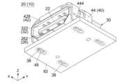
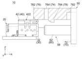
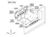
図1及び図2に示されるように、本発明の第1の実施の形態によるコネクタ組立体10は、第1コネクタ20と、第2コネクタ50とを備えている。第1コネクタ20は、レセプタクルであり、回路基板(基板)82に搭載して使用される。第2コネクタ50は、プラグであり、ケーブル86に接続して使用される。即ち、本実施の形態において、第1コネクタ20は、レセプタクルタイプのオンボードコネクタであり、第2コネクタ50は、プラグタイプのケーブルコネクタである。特に、第1コネクタ20は、所謂アングルタイプのレセプタクルである。但し、本発明は、これに限られず、様々なコネクタ組立体に適用可能である。例えば、第1コネクタ20は、プラグであってもよく、第2コネクタ50は、レセプタクルであってもよい。(First embodiment)
As shown in FIGS. 1 and 2, the
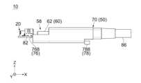
図3及び図4を参照すると、第1コネクタ20と第2コネクタ50とは、接続方向(前後方向:X方向)に沿って互いに接続可能である。より具体的には、図3に示した第1コネクタ20及び第2コネクタ50は、互いに離れた分離状態にあり、第2コネクタ50は、第1コネクタ20の前方(+X側)に位置している。分離状態にある第2コネクタ50を、第1コネクタ20に向かって後方(-X方向)に移動させると、第1コネクタ20及び第2コネクタ50は、互いに接続した接続状態(図4の状態)になる。接続状態において、第1コネクタ20と第2コネクタ50とは、互いに電気的に接続され、これにより、基板82を含む電子機器(図示せず)とケーブル86に接続された他の電子機器(図示せず)とは、互いに電気的に接続される。 Referring to FIGS. 3 and 4, the
以下、第1コネクタ20の構造について説明する。 The structure of the
図5及び図6を参照すると、本実施の形態の第1コネクタ20は、絶縁体からなる第1保持部材22と、導電体からなる複数の第1端子26と、導電体からなる第1シェル30と、高い強度を有する材料からなる第1係合部材40とを備えている。本実施の形態によれば、上述した部材は、全て別体に形成されている。例えば、第1係合部材40は、第1シェル30と別体の部材である。また、本実施の形態の第1コネクタ20は、上述した部材を組み合わせて形成されている。但し、本発明は、これに限られない。例えば、第1係合部材40は、第1シェル30と一体の部材であってもよい。即ち、第1シェル30及び第1係合部材40の夫々は、単一の部材の一部であってもよい。また、第1コネクタ20は、上述した部材に加えて、更に別の部材を備えていてもよい。 5 and 6, the
本実施の形態によれば、第1端子26、第1シェル30及び第1係合部材40の夫々は、金属からなる。詳しくは、これらの部材の夫々は、曲げを有する1枚の金属板である。但し、本発明は、これに限られない。例えば、第1シェル30は、複数の部材を接合して形成してもよい。 According to this embodiment, each of the
図7を参照すると、第1端子26は、第1保持部材22に保持されている。また、第1端子26の夫々は、第1被固定部268を有している。本実施の形態において、第1被固定部268の夫々は、第1コネクタ20を基板82に搭載したとき、基板82の導電パッド822に半田付け等によって接続され固定される。 Referring to FIG. 7, the
図5及び図6を参照すると、第1端子26の夫々は、第1接触部262を有している。第1接触部262は、接続状態(図4参照)において、第2コネクタ50(図4参照)と電気的に接続される。本実施の形態の第1接触部262は、X方向と直交する直交方向(上下方向:Z方向)において2列に分けられている。2列の第1接触部262は、第1保持部材22の板状の部位のZ方向における両面、即ち、上面(+Z側の面)及び下面(-Z側の面)に夫々配置されている。各列の第1接触部262は、X方向及びZ方向の双方と直交する所定方向(横方向:Y方向)に並んでいる。本実施の形態の第1端子26は、上述の構造を有しており、上述のように配置されている。但し、本発明において、第1端子26の構造及び配置は、特に限定されない。 Referring to FIGS. 5 and 6, each of the
図5及び図8を参照すると、本実施の形態の第1シェル30は、第1保持部材22に取り付けられている。第1シェル30は、第1嵌合部32を有している。第1嵌合部32は、主板322と、2つの側板324と、反対板326とを有している。主板322及び反対板326は、第1嵌合部32のZ方向における両側、即ち、上側(+Z側)及び下側(+Z側)に夫々位置している。主板322及び反対板326の夫々は、Z方向と直交する所定平面(XY平面)に沿って延びている。側板324は、第1嵌合部32のY方向における両側に夫々位置している。側板324の夫々は、主板322と反対板326とをZ方向において互いに連結している。本実施の形態の第1嵌合部32は、上述の構造を有している。但し、本発明は、これに限られず、第1嵌合部32の構造は、様々に変形可能である。 Referring to FIGS. 5 and 8, the
本実施の形態の第1嵌合部32は、X方向と直交する直交平面(YZ平面)において、第1保持部材22の大部分を囲んでいる。詳しくは、主板322及び反対板326は、Z方向において、第1保持部材22の両側を夫々覆っている。2つの側板324は、Y方向において、第1保持部材22の両側を夫々覆っている。即ち、第1嵌合部32は、YZ平面において、第1保持部材22に配置された第1接触部262を覆っている。一方、図10に示されるように、本実施の形態の主板322には、複数の孔部323が形成されている。従って、第1嵌合部32は、YZ平面において、第1接触部262を完全には覆っていない。但し、本発明は、これに限られず、第1嵌合部32は、YZ平面において、第1接触部262を完全に覆っていてもよい。即ち、第1嵌合部32は、YZ平面において、第1接触部262を少なくとも部分的に覆っていればよい。 The first
図9及び図10に示されるように、本実施の形態の第1シェル30は、複数の被固定部38を有している。本実施の形態によれば、側板324の夫々に、2つの被固定部38が設けられている。被固定部38の夫々は、側板324から、Z方向に沿って主板322及び反対板326から離れるように下方(-Z方向)に向かって延びている。本実施の形態によれば、第1コネクタ20を基板82に搭載したとき、被固定部38の夫々は、基板82に圧入されて固定され、グランドパターン(図示せず)に接続される。このとき、第1嵌合部32は、基板82上に位置する。第1嵌合部32の先端328(+X側の端である前端)は、X方向において基板82の縁を越えて突出する。但し、本発明は、これに限られず、第1シェル30の基板82上の配置は、様々に変形可能である。 As shown in FIGS. 9 and 10, the
図5及び図8を参照すると、本実施の形態の第1係合部材40は、第1シェル30に取り付けられている。第1係合部材40は、平板部42と、2つの腕部44とを有している。平板部42は、XY平面に沿って延びており、XY平面において概ね矩形形状を有している。即ち、本実施の形態の平板部42は、Z方向と直交する矩形板である。腕部44は、第1係合部材40のY方向における両側に夫々位置している。腕部44は、Y方向における平板部42の両端から、Z方向に沿って互いに平行に延びている。本実施の形態の第1係合部材40は、上述の構造を有している。但し、本発明は、これに限られず、第1係合部材40の構造は、様々に変形可能である。例えば、腕部44の夫々は、必要に応じて設ければよい。平板部42は、Z方向と僅かに斜交していてもよい。即ち、平板部42は、Z方向と交差していてもよい。 Referring to FIGS. 5 and 8, the
本実施の形態の第1係合部材40は、YZ平面において、第1シェル30を部分的に囲んでいる。詳しくは、平板部42は、Z方向において、第1シェル30の主板322を、距離をあけて覆っている。2つの腕部44は、Y方向において、第1シェル30の2つの側板324を夫々覆っている。即ち、本実施の形態の第1係合部材40は、第1シェル30を部分的に覆うように配置されている。但し、本発明は、これに限られず、第1係合部材40の配置は、様々に変形可能である。 The
図9及び図10に示されるように、本実施の形態の第1係合部材40は、複数の被固定部48を有している。本実施の形態によれば、腕部44の夫々に、1つの被固定部48が設けられている。被固定部48の夫々は、腕部44からZ方向に沿って平板部42から離れるように延びている。図5、図6及び図9を参照すると、本実施の形態によれば、第1コネクタ20を基板82に搭載したとき、被固定部48の夫々は、第1シェル30の被固定部38のうちの1つと共に基板82に圧入されて固定される。このとき、平板部42の先端428(+X側の端である前端)は、X方向において基板82の縁と同じ位置にある。但し、本発明は、これに限られず、第1係合部材40の基板82上の配置は、様々に変形可能である。また、第1係合部材40は、基板82に取付けることなく、第1シェル30のみに取付けてもよい。 As shown in FIGS. 9 and 10, the first engaging
図5、図7及び図9に示されるように、第1係合部材40には、係合凹部422が形成されている。本実施の形態の係合凹部422は、平板部42に形成されている。係合凹部422は、Z方向において、第1シェル30の外側に位置している。より具体的には、平板部42は、Z方向において、第1シェル30の第1嵌合部32(主板322)から離れており、これにより、係合凹部422は、Z方向において、主板322から離れている。 As shown in FIGS. 5, 7, and 9, an
図5及び図9に示されるように、本実施の形態の第1係合部材40は、折返し部43を有している。折返し部43は、弧状の部位と、平板状の部位とを有している。折返し部43の弧状の部位は、平板部42の先端428から第1嵌合部32の主板322に向かって、XZ平面において半円弧を描きつつ延びている。折返し部43の平板状の部位は、弧状の部位から、X方向に沿って先端428から離れるように延びており、Z方向において平板部42と主板322との間に位置している。即ち、平板部42及び係合凹部422は、Z方向において、第1嵌合部32の主板322から、折返し部43の板厚寸法よりも大きな距離寸法だけ離れている。本実施の形態の平板部42は、折返し部43によって補強されており撓み難い。即ち、係合凹部422は、Z方向において移動し難い。但し、本発明は、これに限られず、折返し部43は、必要に応じて設ければよい。 As shown in FIGS. 5 and 9, the first engaging
図5、図7及び図9に示されるように、本実施の形態の腕部44の夫々は、部分的に切り欠かれており、これにより、バネ片442が形成されている。バネ片442の夫々は、腕部44の切欠きの内縁からY方向の内側に向かって延びており、弾性変形可能である。 As shown in FIGS. 5, 7, and 9, each of the
図10に示されるように、本実施の形態の第1シェル30は、複数の内側位置決め部(開口部)36を有している。一方、本実施の形態の第1係合部材40は、内側位置決め部36に夫々対応する複数の外側位置決め部444を有している。内側位置決め部36の夫々は、第1嵌合部32に形成された開口部であり、YZ平面において、第1嵌合部32の内部及び外部に開口している。外側位置決め部444の夫々は、YZ平面の内側に向かって突出している。 As shown in FIG. 10, the
図5及び図10を参照すると、内側位置決め部36の夫々と、対応する外側位置決め部444とは、互いに強固に組み合わされており、これにより、第1係合部材40は、第1シェル30に対して位置決めされており、且つ、固定されている。より具体的には、外側位置決め部444は、内側位置決め部36に夫々受容され、内側位置決め部36を少なくとも部分的に夫々塞いでいる。第1係合部材40の2つの腕部44は、第1嵌合部32をY方向に挟んでいる。腕部44のバネ片442は、弾性変形しつつ第1嵌合部32の主板322に押し付けられている。第1コネクタ20が基板82に搭載されたとき、腕部44と基板82とは、第1嵌合部32をZ方向に挟む。 5 and 10, each of the
図10を参照すると、本実施の形態によれば、内側位置決め部36の夫々は、第1嵌合部32の側板324に形成された凹みであり、外側位置決め部444の夫々は、腕部44に形成された突起である。但し、本発明は、これに限られない。例えば、内側位置決め部36と外側位置決め部444とが夫々対応して設けられている限り、内側位置決め部36及び外側位置決め部444の構造及び配置は、特に限定されない。 Referring to FIG. 10, according to the present embodiment, each of the
本実施の形態によれば、第1係合部材40は、内側位置決め部36と外側位置決め部444とを夫々組み合わせた後、溶接によって第1シェル30に更に固定されている。但し、本発明は、これに限られず、第1係合部材40は、必要に応じて、第1シェル30に溶接すればよい。 According to the present embodiment, the
以下、第2コネクタ50の構造について説明する。 The structure of the
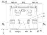
図1及び図2を参照すると、本実施の形態の第2コネクタ50は、絶縁体からなる第2保持部材52と、導電体からなる複数の第2端子56と、導電体からなる第2シェル60と、絶縁体からなる第2係合部材70とを備えている。但し、本発明は、これに限られず、第2コネクタ50は、上述した部材に加えて、更に別の部材を備えていてもよい。また、第2係合部材70は、金属製であってもよい。 Referring to FIGS. 1 and 2, the
図1を参照すると、本実施の形態の第2コネクタ50は、絶縁体からなる保護部材88によって保護されたケーブル86に取付けられている。詳しくは、保護部材88をモールド成型する際、第2シェル60及び第2係合部材70は、保護部材88に接合され、これにより、第2係合部材70は、第2シェル60に対して位置決めされる。但し、本発明において、第2コネクタ50をケーブル86に取付ける方法は、特に限定されない。 Referring to FIG. 1, the
図2を参照すると、本実施の形態によれば、第2端子56及び第2シェル60の夫々は、金属からなる。詳しくは、これらの部材の夫々は、曲げを有する1枚の金属板である。但し、本発明は、これに限られない。例えば、第2シェル60は、複数の部材を接合して形成してもよい。 Referring to FIG. 2, according to the present embodiment, each of the
図2及び図16を参照すると、第2端子56は、第2保持部材52に保持されている。第2端子56の夫々は、第2被固定部(図示せず)を有している。本実施の形態において、第2被固定部の夫々は、第2コネクタ50をケーブル86に取付けたとき、ケーブル86の導電線(図示せず)に半田付け等によって接続され固定される。 Referring to FIGS. 2 and 16, the
図17を参照すると、第2端子56は、第1コネクタ20の第1端子26に夫々対応して設けられている。図2、図16及び図17を参照すると、第2端子56の夫々は、第2接触部562を有している。図16及び図17を参照すると、第2接触部562の夫々は、接続状態において、対応する第1接触部262と接触し、これにより、第2コネクタ50は、第1コネクタ20と電気的に接続される。上述のように第1接触部262が第2接触部562と夫々接触するように配置されている限り、第2端子56の構造及び数は、特に限定されない。 Referring to FIG. 17, the
図1及び図3を参照すると、第2シェル60は、第2嵌合部62を有している。図17を参照すると、第2シェル60は、第2保持部材52に取り付けられており、第2嵌合部62は、YZ平面において、第2保持部材52を囲んでいる。本実施の形態の第2嵌合部62は、孔のない1枚の金属片を、X方向と平行な軸を中心に曲げて加締めることにより形成されている。即ち、本実施の形態の第2嵌合部62は、YZ平面において、第2保持部材52を隙間なく囲んでおり、これにより、第2保持部材52に配置された第2接触部562を完全に覆っている。但し、本発明は、これに限られず、第2嵌合部62は、YZ平面において、第2接触部562を部分的に覆っていてもよい。即ち、第2嵌合部62は、YZ平面において、第2接触部562を少なくとも部分的に覆っていればよい。 Referring to FIGS. 1 and 3, the
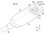
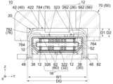
図1及び図2を参照すると、本実施の形態の第2係合部材70は、基部72と、保護部74と、係合腕78とを有している。第2係合部材70は、YZ平面において、第2保持部材52及び第2シェル60の外側に位置している。基部72は、YZ平面において、第2嵌合部62を除いて第2シェル60を完全に覆っている。図11を参照すると、保護部74は、Z方向において基部72から突出した部位と、X方向において基部72から突出した部位とを有している(基部72と保護部74との間の境界を示す破線参照)。図1及び図2を参照すると、保護部74は、XY平面において、係合腕78の大部分を、距離をあけて囲んでいる。係合腕78は、保護部74に繋がっており、Z方向において基部72から離れている。本実施の形態の第2係合部材70は、上述の構造を有している。但し、本発明は、これに限られず、第2係合部材70の構造は、様々に変形可能である。 Referring to FIGS. 1 and 2, the
図1及び図3を参照すると、本実施の形態の第2係合部材70は、YZ平面において、第2嵌合部62を部分的に囲んでいる。詳しくは、第2嵌合部62は、基部72からX方向に沿って突出している。保護部74及び係合腕78は、基部72からX方向に沿って部分的に突出しており、Z方向において、第2嵌合部62を覆っている。即ち、第2係合部材70は、第2嵌合部62のZ方向における両側のうちの一方(+Z側である上側)を覆っている。一方、第2係合部材70は、第2嵌合部62のZ方向における両側のうちの他方(-Z側である下側)を覆う部位を有していない。即ち、第2係合部材70は、Z方向において保護部74及び係合腕78の反対側に位置する空間(受容部58)を有している。第2嵌合部62は、受容部58の内部に位置している。 Referring to FIGS. 1 and 3, the second engaging
上述のように、本実施の形態の第2係合部材70は、第2嵌合部62のZ方向における両側のうちの一方のみを覆っている。即ち、本実施の形態の第2係合部材70は、YZ平面において、第2嵌合部62を部分的に覆うように配置されている。但し、本発明は、これに限られない。例えば、第2係合部材70は、YZ平面において、第2嵌合部62を完全に覆っていてもよい。即ち、第2係合部材70は、YZ平面において、第2嵌合部62を少なくとも部分的に覆っていればよい。 As described above, the second engaging
図1から図3まで及び図11に示されるように、本実施の形態の係合腕78は、係合支持部782と、係合凸部784と、2つの連結部786と、操作部788とを有している。係合支持部782は、X方向に沿って延びている。係合凸部784は、係合支持部782のX方向における両端のうちの一方(-X側の端である後端)に設けられている。係合凸部784は、Z方向において第2嵌合部62に向かって突出している。図1から図3までを参照すると、操作部788は、係合支持部782のX方向における両端のうちの他方(+X側の端である前端)に設けられている。操作部788は、Z方向において、基部72から離れており、且つ、基部72と対向している。連結部786は、係合支持部782の操作部788近傍の部位のY方向両側に夫々設けられている。連結部786の夫々は、係合支持部782からY方向外側に延びており、保護部74に繋がっている。 As shown in FIGS. 1 to 3 and 11, the
本実施の形態の係合支持部782は、連結部786を支点部として回転するように弾性変形可能である。一般的に、弾性変形可能に形成された係合支持部782は、比較的破損し易い。一方、本実施の形態の保護部74は、XY平面において、係合支持部782を覆っており、これにより、係合支持部782の破損を防止している。 The
係合凸部784は、係合支持部782の弾性変形に伴って、Z方向に移動可能である。例えば、操作部788を基部72に向かって押すと、係合凸部784は、Z方向において第2嵌合部62から離れるように移動する。係合凸部784のX方向における両側面のうちの一方(+X側の面である前面)は、X方向と直交する垂直面である。一方、係合凸部784のX方向における両側面のうちの他方(-X側の面である後面)は、緩やかに曲がる弧状面である。 The engagement
以上の説明を纏めると、第2係合部材70は、係合凸部784と、係合支持部782とを有している。係合凸部784は、係合支持部782に支持されており、Z方向に移動可能である。係合凸部784は、Z方向において、第2シェル60の外側に位置しており、且つ、第2シェル60に向かって突出している。本実施の形態によれば、係合凸部784及び係合支持部782は、操作部788と共に、係合腕78に設けられている。但し、第2係合部材70の構造は、本実施の形態に限定されない。例えば、第2係合部材70は、操作部788を有していなくてもよい。係合凸部784がZ方向に移動可能である限り、係合支持部782は、弾性変形しなくてもよい。例えば、係合支持部782は、ピンである連結部を中心に回転可能であってもよい。保護部74は、必要に応じて設ければよい。 To summarize the above description, the
図1及び図11を参照すると、本実施の形態の第2係合部材70は、ガイド部76を有している。ガイド部76は、ガイド主部762と、2つのガイド側部764とを有している。ガイド主部762は、YZ平面において、Y方向に沿って延びている。ガイド側部764は、ガイド主部762のY方向における両端から、Z方向に沿って第2嵌合部62に向かって互いに平行に延びている。本実施の形態によれば、ガイド主部762及びガイド側部764は、保護部74の一部である。詳しくは、ガイド主部762及びガイド側部764は、保護部74のうちX方向において基部72から突出した部位である。但し、本発明は、これに限られない。例えば、ガイド主部762及びガイド側部764は、保護部74と別の部位であってもよい。 Referring to FIGS. 1 and 11, the second engaging
図17を参照すると、Z方向において、ガイド主部762と第2嵌合部62との間の距離寸法D2は、第1係合部材40のZ方向外側の面と主板322のZ方向内側の面との間の距離寸法D1よりも僅かに大きい。加えて、Y方向において、2つのガイド側部764の間の距離寸法DGは、第1コネクタ20の幅寸法W1よりも僅かに大きい。図12から図14までを参照すると、上述のように配置されたガイド部76は、第1コネクタ20と第2コネクタ50とが互いに接続する際、第2嵌合部62の第1嵌合部32に対するYZ平面における位置をガイドする。但し、本発明は、これに限られず、ガイド部76は、必要に応じて設ければよい。また、ガイド部76を設ける場合でも、ガイド部76の構造は、本実施の形態に限定されない。 Referring to FIG. 17, in the Z direction, the distance dimension D2 between the guide
図3に示されるように、X方向において、第2嵌合部62の先端628(-X側の端である後端)は、ガイド部76の先端768(-X側の端である後端)と係合凸部784との間に位置している。この配置により、ガイド部76は、第1コネクタ20と第2コネクタ50とが互いに接続する際、第2嵌合部62が第1嵌合部32に接近する前に、第2嵌合部62を第1嵌合部32に対して位置決めする。但し、本発明は、これに限られず、ガイド部76の配置は、必要に応じて変形可能である。 As shown in FIG. 3, in the X direction, the tip 628 (the rear end which is the end on the -X side) of the second
以下、第2コネクタ50を第1コネクタ20に接続する際の接続操作、及び、第1コネクタ20と接続した第2コネクタ50を第1コネクタ20から抜去する際の抜去操作について説明する。接続操作及び抜去操作についての以下の説明において、接続方向(X方向)のうちの-X方向を嵌合方向といい、+X方向を抜去方向という。 The connection operation when connecting the
図12を参照すると、コネクタ組立体10は、分離状態にあり、第2コネクタ50の第2嵌合部62は、第1コネクタ20の第1嵌合部32とX方向において対向している。図12及び図13を参照すると、第2コネクタ50を、嵌合方向(-X方向)に沿って第1コネクタ20に向かって移動すると、第2嵌合部62は、第1嵌合部32に対して位置決めされつつ、第1嵌合部32に接近する。図13を参照すると、第2嵌合部62の先端628が第1嵌合部32の先端328(+X側の端である前端)に到達したとき、係合凸部784は、第1係合部材40の折返し部43から離れている。 Referring to FIG. 12, the
図14を参照すると、第2コネクタ50を、-X方向に沿って更に移動すると、第2嵌合部62は、第1嵌合部32の内部に部分的に受容され、係合凸部784の弧状面は、折返し部43の弧状の部位と突き当たる。第2コネクタ50を、-X方向に沿って更に移動すると、係合支持部782は、弾性変形し、係合凸部784は、Z方向において移動して、第1係合部材40の平板部42の上に位置する(図14の破線参照)。このとき、折返し部43の弧状の部位は、係合凸部784の弧状面をガイドし、係合凸部784は、平板部42の上にスムーズに移動する。第2コネクタ50を、-X方向に沿って更に移動すると、係合凸部784は、平板部42の上をスライドする。 Referring to FIG. 14, when the
図15を参照すると、第2コネクタ50を、-X方向に沿って更に移動すると、第2嵌合部62は、第1嵌合部32と嵌合する。このとき、コネクタ組立体10は、接続状態にある。本実施の形態によれば、接続状態において、第2係合部材70の基部72は、X方向において第1嵌合部32から離れており、第2嵌合部62の基部72近傍の部位は、第1嵌合部32の外部に位置している。但し、本発明は、これに限られず、接続状態における第1嵌合部32と第2嵌合部62との位置関係は、必要に応じて変形可能である。 Referring to FIG. 15, when the
接続状態において、係合凸部784は、平板部42の係合凹部422に到達する。このとき、係合支持部782は、初期形状に復元し、係合凸部784は、係合凹部422に受容される。この結果、接続状態がロックされる。即ち、接続状態において、係合凸部784と係合凹部422とは、互いに係合して、接続状態をロックする。より具体的には、接続状態にある第2コネクタ50を、抜去方向(+X方向)に引いたとしても、接続状態が維持される。即ち、本実施の形態のコネクタ組立体10は、係合凸部784及び係合凹部422からなるロック機構を備えている。 In the connected state, the engagement
本実施の形態の係合凸部784は、Z方向において、平板部42の厚さ寸法よりも大きな距離寸法(突出距離寸法)だけ、係合支持部782から突出している。また、Z方向における平板部42と主板322との間の距離寸法は、係合凸部784の突出距離寸法よりも大きい。この構造により、係合凹部422に受容された係合凸部784は、第1コネクタ20のZ方向内側に深く挿入される。また、係合凸部784の垂直面は、X方向において係合凹部422の内縁と対向して接続状態をロックする。更に、高い強度を有する平板部42は、折返し部43によって補強されており、力を受けても撓み難い。上述のロック機構により、接続状態は、より確実にロックされる。但し、本発明のロック機構は、本実施の形態に限られず、様々に変形可能である。 The engagement
図16及び図17を参照すると、接続状態において、第1端子26の第1接触部262は、第2端子56の第2接触部562と夫々接触する。接続状態において、第1嵌合部32と第2嵌合部62とは、互いに嵌合して、嵌合部16を形成する。本実施の形態の第2嵌合部62は、YZ平面において隙間を有していない。従って、嵌合部16は、第1嵌合部32が孔部323を有していたとしても、第1接触部262と第2接触部562との間の接触領域12を、YZ平面において完全に囲む。この構造によれば、EMI(電磁干渉:Electro Magnetic Interference)対策の妨げになるような孔の形成を防止できる。 Referring to FIGS. 16 and 17, in the connected state, the
以上に説明したように、本実施の形態によれば、ロック機構を備えており、且つ、EMI対策を施したコネクタ組立体10を提供できる。コネクタ組立体10は、高速信号を伝送する際にも使用可能である。本実施の形態によれば、ロック機構を有する部材をEMI対策用の部材と分けることによって、ロック機能及びEMI対策機能が両立している。 As described above, according to the present embodiment, it is possible to provide the
前述したように、本実施の形態によれば、第1嵌合部32に孔部323が形成されている一方、第2嵌合部62には、孔が形成されていない。但し、本発明は、これに限られない。接続状態において形成される嵌合部16に孔が形成されない限り、第2嵌合部62に孔が形成されていてもよい。換言すれば、第1嵌合部32及び第2嵌合部62の夫々には、接続状態において重ならない1以上の孔が形成されていてもよい。 As described above, according to the present embodiment, the first
図3及び図15を参照すると、第1コネクタ20及び第2コネクタ50が接続状態にあるとき、係合腕78の操作部788を基部72に向けて押すと、係合凸部784は、Z方向に沿って移動して、係合凹部422の外に出る。即ち、ロック状態が解除される。ロック状態を解除しつつ、第2コネクタ50を抜去方向(+X方向)に沿って移動させると、第2コネクタ50を、第1コネクタ20から抜去できる。 3 and 15, when the
図12及び図15を参照すると、本実施の形態によれば、第2コネクタ50の受容部58は、接続状態において、第1コネクタ20を部分的に受容する。受容部58が設けられているため、ガイド部76が第1コネクタ20に向かって突出していても、第2コネクタ50を、第1コネクタ20に接続できる。一方、ガイド部76は、第1嵌合部32への第2嵌合部62の逆挿入を防止する。より具体的には、図18を参照すると、第2嵌合部62を、第1嵌合部32に上下逆に挿入しようとすると、ガイド部76の先端768が基板82と突き当たって受け止められる。従って、仮に、第2嵌合部62が上下逆にしても第1嵌合部32に挿入可能な形状を有していたとしても、第2コネクタ50は、第1コネクタ20に接続できない。また、先端768は、第2コネクタ50が第1コネクタ20と接触する前に基板82と突き当たるため、誤嵌合に起因する金属屑の発生を防止できる。Referring to FIGS. 12 and 15, according to the present embodiment, the receiving
本発明は、既に説明した第1の実施の形態及び様々な変形例に加えて、更に様々に適用可能である。以下、本発明の第2の実施の形態について説明する。 In addition to the first embodiment and various modifications described above, the present invention can be applied in various other ways. A second embodiment of the present invention will be described below.
(第2の実施の形態)
図19に示されるように、本発明の第2の実施の形態によるコネクタ組立体10Aは、第1コネクタ20(図1参照)と異なる第1コネクタ20Aと、コネクタ組立体10(図1参照)と同じ第2コネクタ50とを備えている。但し、本発明は、これに限られず、コネクタ組立体10Aは、第2コネクタ50と異なる第2コネクタを備えていてもよい。(Second embodiment)
As shown in FIG. 19, a
図25及び図27を参照すると、第1コネクタ20Aと第2コネクタ50とは、コネクタ組立体10と同様に、接続方向(前後方向:X方向)に沿って互いに接続可能である。本実施の形態の第1コネクタ20Aは、第1コネクタ20(図1参照)と同様に、レセプタクルタイプのオンボードコネクタである。但し、第1コネクタ20Aは、所謂ストレートタイプのレセプタクルである。以下、第1コネクタ20Aの構造について、第1コネクタ20との相違点を中心に説明する。 Referring to FIGS. 25 and 27, like the
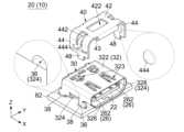
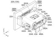
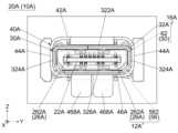
図20及び図21を参照すると、本実施の形態の第1コネクタ20Aは、絶縁体からなる第1保持部材22Aと、導電体からなる複数の第1端子26Aと、導電体からなる第1シェル30Aと、高い強度を有する材料からなる第1係合部材40Aとを備えている。本実施の形態によれば、第1係合部材40Aは、第1シェル30Aと別体の部材である。また、第1端子26A、第1シェル30A及び第1係合部材40Aの夫々は、金属からなる。但し、本発明は、これに限られない。例えば、第1係合部材40Aは、第1シェル30Aと一体の部材であってもよい。また、第1コネクタ20Aは、上述した部材に加えて、更に別の部材を備えていてもよい。 Referring to FIGS. 20 and 21, the
図22を参照すると、第1端子26Aは、第1保持部材22Aに保持されている。図20を参照すると、第1端子26Aの夫々は、第1接触部262Aと、第1被固定部268Aとを有している。本実施の形態において、第1被固定部268Aの夫々は、第1コネクタ20Aを基板82Aに搭載したとき、基板82Aの導電パッド822Aに半田付け等によって接続され固定される。図20、図21及び図23を参照すると、第1端子26Aは、第2コネクタ50(図17参照)の第2端子56(図17参照)に夫々対応して設けられている。第1接触部262Aの夫々は、接続状態(図27参照)において、対応する第2端子56の第2接触部562(図17参照)と夫々接触し、これにより、第1コネクタ20Aは、第2コネクタ50と電気的に接続される。 Referring to FIG. 22, the
図20及び図23を参照すると、本実施の形態の第1シェル30Aは、第1保持部材22Aに取り付けられている。第1シェル30Aは、第1嵌合部32Aを有している。第1嵌合部32Aは、主板322Aと、2つの側板324Aと、反対板326Aとを有している。主板322A及び反対板326Aは、第1嵌合部32AのX方向と直交する直交方向(上下方向:Z方向)における両側に夫々位置している。主板322A及び反対板326Aの夫々は、Z方向と直交する所定平面(XY平面)に沿って延びている。側板324Aは、第1嵌合部32AのX方向及びZ方向の双方と直交する所定方向(横方向:Y方向)における両側に夫々位置している。側板324Aの夫々は、主板322Aと反対板326AとをZ方向において互いに連結している。 Referring to FIGS. 20 and 23, the
本実施の形態の第1嵌合部32Aは、X方向と直交する直交平面(YZ平面)において、第1保持部材22Aを囲んでいる。特に、第1嵌合部32Aは、YZ平面において、第1保持部材22Aに配置された第1接触部262Aを少なくとも部分的に覆っている。 The first
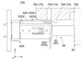
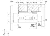
図22及び図24に示されるように、本実施の形態の第1シェル30Aは、複数の被固定部38Aを有している。本実施の形態によれば、主板322A及び反対板326Aの夫々に、2つの被固定部38Aが設けられている。被固定部38Aの夫々は、全体としてX方向に沿って延びている。第1コネクタ20Aを基板82Aに搭載したとき、被固定部38Aの夫々は、基板82Aに圧入されて固定され、グランドパターン(図示せず)に接続される。基板82Aは、YZ平面に沿って延びるように配置されている。即ち、第1コネクタ20Aは、使用時に、YZ平面に沿って延びる基板82Aに固定され、第1嵌合部32Aは、基板82Aと直交するX方向に沿って延びる。 As shown in FIGS. 22 and 24, the
図20、図21及び図23を参照すると、本実施の形態の第1係合部材40Aは、第1シェル30Aに取り付けられている。第1係合部材40Aは、平板部42Aと、2つの側板部44Aと、反対部46Aとを有している。平板部42A及び反対部46Aは、第1係合部材40AのZ方向における両側に夫々位置している。平板部42A及び反対部46Aの夫々は、Z方向と交差している。反対部46Aは、Y方向に並んだ2つの部位を含んでいる。側板部44Aは、第1係合部材40AのY方向における両側に夫々位置している。側板部44Aの夫々は、平板部42Aと反対部46AとをZ方向において互いに連結している。本実施の形態の第1係合部材40Aは、上述の構造を有している。但し、本発明は、これに限られず、第1係合部材40Aの構造は、様々に変形可能である。 Referring to FIGS. 20, 21, and 23, the
本実施の形態の第1係合部材40Aは、YZ平面において、第1シェル30Aの大部分を囲んでいる。図23を参照すると、平板部42Aは、Z方向において、第1シェル30Aの主板322Aを、距離をあけて覆っている。2つの側板部44Aは、Y方向において、第1シェル30Aの2つの側板324Aを夫々覆っている。反対部46Aは、Z方向において、第1シェル30Aの反対板326Aを覆っている。本実施の形態の第1係合部材40Aは、第1シェル30Aを上述のように覆うように配置されている。但し、本発明は、これに限られず、第1係合部材40Aの配置は、様々に変形可能である。 The
図20及び図22を参照すると、第1係合部材40Aには、係合凹部422Aが形成されている。本実施の形態の係合凹部422Aは、平板部42Aに形成されている。係合凹部422Aは、Z方向において、第1シェル30Aの外側に位置している。より具体的には、平板部42Aは、Z方向において、第1シェル30Aの第1嵌合部32A(主板322A)から離れており、これにより、係合凹部422Aは、Z方向において、主板322Aから離れている。図20に示されるように、本実施の形態の第1係合部材40Aは、折返し部43(図5参照)と同様な折返し部43Aを有している。平板部42Aは、折返し部43Aによって補強されており撓み難い。即ち、係合凹部422Aは、Z方向において移動し難い。 Referring to FIGS. 20 and 22, an
図20及び図24に示されるように、本実施の形態の第1シェル30Aは、2つの内側位置決め部(開口部)36Aを有している。一方、本実施の形態の第1係合部材40Aは、内側位置決め部36Aに夫々対応する2つの外側位置決め部444Aを有している。内側位置決め部36Aは、第1嵌合部32Aの側板324Aに夫々形成された孔である。即ち、内側位置決め部36Aの夫々は、第1嵌合部32Aに形成された開口部であり、YZ平面において、第1嵌合部32Aの内部及び外部に開口している。外側位置決め部444Aは、側板部44Aに夫々形成されたバネ片442Aの端部である。バネ片442Aの夫々は、全体としてX方向に沿って延びており、弾性変形可能である。外側位置決め部444Aの夫々は、バネ片442Aに支持されており、YZ平面の内側に向かって突出している。 As shown in FIGS. 20 and 24, the
本実施の形態によれば、外側位置決め部444Aは、内側位置決め部36Aに夫々受容され、内側位置決め部36Aを少なくとも部分的に夫々塞いでいる。第1係合部材40Aの側板部44AのX方向における両端のうちの一方(-X側の端である後端)は、第1保持部材22Aの一部と、X方向において接触又は僅かな距離をあけて対向している。加えて、外側位置決め部444Aの夫々のX方向における両端のうちの一方(+X側の端である前端)は、内側位置決め部36Aの内縁と、X方向において接触又は僅かな距離をあけて対向している。このように配置された第1係合部材40Aは、X方向に沿った力を受けても、第1シェル30Aから抜け落ち難い。即ち、内側位置決め部36Aの夫々と、対応する外側位置決め部444Aとは、互いに組み合わされており、これにより、第1係合部材40Aは、第1シェル30Aに対して位置決めされており、且つ、固定されている。 According to this embodiment, the
図20、図21、図23を参照すると、第1コネクタ20Aは、2つの受止部468Aを有している。本実施の形態の受止部468Aは、第1係合部材40Aの反対部46Aの2つの部位に夫々繋がっており、Y方向に並んでいる。図24を参照すると、受止部468Aの夫々は、X方向において、第1嵌合部32Aの先端328A(+X側の端である前端)近傍に位置しており、Z方向に沿って第1嵌合部32Aから離れるように延びている。即ち、受止部468Aは、第1コネクタ20AのZ方向における両側のうちの一方にのみ設けられている。本実施の形態によれば、2つの受止部468Aが設けられている。但し、本発明における受止部468Aの数は、特に限定されない。例えば、受止部468Aの数は、1であってもよい。 Referring to FIGS. 20, 21, and 23, the
以下、第2コネクタ50を第1コネクタ20Aに接続する際の接続操作、及び、第1コネクタ20Aと接続した第2コネクタ50を第1コネクタ20Aから抜去する際の抜去操作について、第1の実施の形態との相違点を中心に説明する。 Hereinafter, the connection operation when connecting the
図25から図27までを参照すると、分離状態にある第2コネクタ50を、嵌合方向(-X方向)に沿って第1コネクタ20Aに向かって移動すると、第1コネクタ20Aと第2コネクタ50とは、互いに接続した接続状態になる。ガイド部76は、第1コネクタ20Aと第2コネクタ50とが互いに接続する際、第1の実施の形態と同様に、第2嵌合部62の第1嵌合部32Aに対するYZ平面における位置をガイドする。 Referring to FIGS. 25 to 27, when the
接続状態において、第2係合部材70の係合凸部784は、第1係合部材40Aの平板部42Aの係合凹部422Aに受容される。この結果、接続状態がロックされる。即ち、接続状態において、係合凸部784と係合凹部422Aとは、互いに係合して、接続状態をロックする。本実施の形態のコネクタ組立体10Aは、係合凸部784及び係合凹部422Aからなるロック機構を備えている。 In the connected state, the
図23及び図27を参照すると、第1コネクタ20Aと第2コネクタ50とが互いに接続した接続状態において、第1端子26Aの第1接触部262Aは、第2端子56の第2接触部562と夫々接触する。接続状態において、第1嵌合部32Aと第2嵌合部62とは、互いに嵌合して嵌合部16Aを形成し、第1接触部262Aと第2接触部562との間の接触領域12Aを、YZ平面において完全に囲む。即ち、本実施の形態によれば、第1の実施の形態と同様に、ロック機構を備えており、且つ、EMI対策を施したコネクタ組立体10Aを提供できる。 Referring to FIGS. 23 and 27, in the connected state where the
図27を図19と併せて参照すると、第1コネクタ20A及び第2コネクタ50が接続状態にあるとき、係合腕78の操作部788を基部72に向けて押すと、第1の実施の形態と同様に、ロック状態が解除される。ロック状態を解除しつつ、第2コネクタ50を抜去方向(+X方向)に沿って移動させると、第2コネクタ50を、第1コネクタ20Aから抜去できる。 Referring to FIG. 27 in conjunction with FIG. 19, when the
図25及び図27を参照すると、本実施の形態によれば、第2コネクタ50の受容部58は、接続状態において、第1コネクタ20Aを部分的に受容する。図28を参照すると、第2嵌合部62を、第1嵌合部32Aに上下逆に挿入しようとすると、ガイド部76の先端768が第1コネクタ20Aの受止部468Aと突き当たって受け止められる。即ち、第2コネクタ50のガイド部76は、第1嵌合部32Aへの第2嵌合部62の逆挿入を防止する。また、先端768は、第2コネクタ50が第1コネクタ20Aと接触する前に受止部468Aと突き当たるため、誤嵌合に起因する金属屑の発生を防止できる。Referring to FIGS. 25 and 27, according to the present embodiment, the receiving
上述した第2の実施の形態は、第1の実施の形態と同様に様々に変形可能である。また、本発明は、以上に説明した第1の実施の形態、第2の実施の形態、及び、様々な変形例に加えて、更に様々に適用可能である。 The second embodiment described above can be modified in various ways like the first embodiment. Furthermore, the present invention can be applied in various ways in addition to the first embodiment, second embodiment, and various modifications described above.
10,10A コネクタ組立体
12,12A 接触領域
16,16A 嵌合部
20,20A 第1コネクタ
22,22A 第1保持部材
26,26A 第1端子
262,262A 第1接触部
268,268A 第1被固定部
30,30A 第1シェル
32,32A 第1嵌合部
322,322A 主板
323 孔部
324,324A 側板
326,326A 反対板
328,328A 先端
36,36A 内側位置決め部(開口部)
38,38A 被固定部
40,40A 第1係合部材
42,42A 平板部
422,422A 係合凹部
428 先端
43,43A 折返し部
44 腕部
442,442A バネ片
444,444A 外側位置決め部
44A 側板部
46A 反対部
468A 受止部
48 被固定部
50 第2コネクタ
52 第2保持部材
56 第2端子
562 第2接触部
58 受容部
60 第2シェル
62 第2嵌合部
628 先端
70 第2係合部材
72 基部
74 保護部
76 ガイド部
762 ガイド主部
764 ガイド側部
768 先端
78 係合腕
782 係合支持部
784 係合凸部
786 連結部
788 操作部
82,82A 回路基板(基板)
822,822A 導電パッド
86 ケーブル
88 保護部材10,
38, 38A Fixed
822,822A
Claims (10)
Translated fromJapanese前記第1コネクタと前記第2コネクタとは、接続方向に沿って互いに接続可能であり、
前記第1コネクタは、第1保持部材と、複数の第1端子と、第1シェルと、第1係合部材とを備えており、
前記第1端子は、前記第1保持部材に保持されており、
前記第1端子の夫々は、第1接触部を有しており、
前記第1シェルは、第1嵌合部を有しており、
前記第1嵌合部は、前記接続方向と直交する直交平面において、前記第1接触部を少なくとも部分的に覆っており、
前記第1係合部材は、前記第1シェルに固定されており、
前記第1係合部材には、係合凹部が形成されており、
前記係合凹部は、前記接続方向と直交する直交方向において、前記第1シェルの外側に位置しており、
前記第2コネクタは、第2保持部材と、複数の第2端子と、第2シェルと、第2係合部材とを備えており、
前記第2端子は、前記第2保持部材に保持されており、
前記第2端子の夫々は、第2接触部を有しており、
前記第2シェルは、第2嵌合部を有しており、
前記第2嵌合部は、前記直交平面において、前記第2接触部を少なくとも部分的に覆っており、
前記第2係合部材は、前記直交平面において、前記第2嵌合部を少なくとも部分的に覆っており、
前記第2係合部材は、係合凸部と、係合支持部とを有しており、
前記係合凸部は、前記係合支持部に支持されており、前記直交方向に移動可能であり、
前記係合凸部は、前記直交方向において、前記第2シェルの外側に位置しており、且つ、前記第2シェルに向かって突出しており、
前記第1コネクタと前記第2コネクタとが互いに接続した接続状態において、前記第1接触部は、前記第2接触部と夫々接触し、
前記接続状態において、前記第1嵌合部と前記第2嵌合部とは、互いに嵌合して、前記第1接触部と前記第2接触部との間の接触領域を、前記直交平面において完全に囲み、
前記接続状態において、前記係合凸部と前記係合凹部とは、互いに係合して、前記接続状態をロックし、
前記第2係合部材は、前記第2嵌合部の前記直交方向における両側のうちの一方のみを覆っている
コネクタ組立体。A connector assembly comprising a first connector and a second connector,
The first connector and the second connector are connectable to each other along a connection direction,
The first connector includes a first holding member, a plurality of first terminals, a first shell, and a first engaging member,
The first terminal is held by the first holding member,
Each of the first terminals has a first contact portion,
The first shell has a first fitting part,
The first fitting portion at least partially covers the first contact portion in an orthogonal plane perpendicular to the connection direction,
the first engagement member is fixed to the first shell,
An engagement recess is formed in the first engagement member,
The engagement recess is located outside the first shell in a direction orthogonal to the connection direction,
The second connector includes a second holding member, a plurality of second terminals, a second shell, and a second engagement member,
The second terminal is held by the second holding member,
Each of the second terminals has a second contact portion,
The second shell has a second fitting part,
The second fitting portion at least partially covers the second contact portion in the orthogonal plane,
The second engaging member at least partially covers the second fitting part in the orthogonal plane,
The second engagement member has an engagement convex portion and an engagement support portion,
The engagement convex portion is supported by the engagement support portion and is movable in the orthogonal direction,
The engagement protrusion is located outside the second shell in the orthogonal direction, and protrudes toward the second shell,
In a connected state in which the first connector and the second connector are connected to each other, the first contact portion is in contact with the second contact portion, respectively;
In the connected state, the first fitting part and the second fitting part fit into each other so that the contact area between the first contact part and the second contact part is in the orthogonal plane. completely surrounded,
In the connected state, the engaging protrusion and the engaging recess engage with each other to lock the connected state,
The second engaging member covers only one of both sides of the second fitting portion in the orthogonal direction.
connector assembly.
前記第1コネクタと前記第2コネクタとは、接続方向に沿って互いに接続可能であり、
前記第1コネクタは、第1保持部材と、複数の第1端子と、第1シェルと、第1係合部材とを備えており、
前記第1端子は、前記第1保持部材に保持されており、
前記第1端子の夫々は、第1接触部を有しており、
前記第1シェルは、第1嵌合部を有しており、
前記第1嵌合部は、前記接続方向と直交する直交平面において、前記第1接触部を少なくとも部分的に覆っており、
前記第1係合部材は、前記第1シェルに固定されており、
前記第1係合部材には、係合凹部が形成されており、
前記係合凹部は、前記接続方向と直交する直交方向において、前記第1シェルの外側に位置しており、
前記第2コネクタは、第2保持部材と、複数の第2端子と、第2シェルと、第2係合部材とを備えており、
前記第2端子は、前記第2保持部材に保持されており、
前記第2端子の夫々は、第2接触部を有しており、
前記第2シェルは、第2嵌合部を有しており、
前記第2嵌合部は、前記直交平面において、前記第2接触部を少なくとも部分的に覆っており、
前記第2係合部材は、前記直交平面において、前記第2嵌合部を少なくとも部分的に覆っており、
前記第2係合部材は、係合凸部と、係合支持部とを有しており、
前記係合凸部は、前記係合支持部に支持されており、前記直交方向に移動可能であり、
前記係合凸部は、前記直交方向において、前記第2シェルの外側に位置しており、且つ、前記第2シェルに向かって突出しており、
前記第1コネクタと前記第2コネクタとが互いに接続した接続状態において、前記第1接触部は、前記第2接触部と夫々接触し、
前記接続状態において、前記第1嵌合部と前記第2嵌合部とは、互いに嵌合して、前記第1接触部と前記第2接触部との間の接触領域を、前記直交平面において完全に囲み、
前記接続状態において、前記係合凸部と前記係合凹部とは、互いに係合して、前記接続状態をロックし、
前記第2係合部材は、保護部を有しており、
前記保護部は、前記直交方向と直交する所定平面において、前記係合支持部を覆っている
コネクタ組立体。A connector assembly comprising a first connector and a second connector,
The first connector and the second connector are connectable to each other along a connection direction,
The first connector includes a first holding member, a plurality of first terminals, a first shell, and a first engaging member,
The first terminal is held by the first holding member,
Each of the first terminals has a first contact portion,
The first shell has a first fitting part,
The first fitting portion at least partially covers the first contact portion in an orthogonal plane perpendicular to the connection direction,
the first engagement member is fixed to the first shell,
An engagement recess is formed in the first engagement member,
The engagement recess is located outside the first shell in a direction orthogonal to the connection direction,
The second connector includes a second holding member, a plurality of second terminals, a second shell, and a second engagement member,
The second terminal is held by the second holding member,
Each of the second terminals has a second contact portion,
The second shell has a second fitting part,
The second fitting portion at least partially covers the second contact portion in the orthogonal plane,
The second engaging member at least partially covers the second fitting part in the orthogonal plane,
The second engagement member has an engagement convex portion and an engagement support portion,
The engagement convex portion is supported by the engagement support portion and is movable in the orthogonal direction,
The engagement protrusion is located outside the second shell in the orthogonal direction, and protrudes toward the second shell,
In a connected state in which the first connector and the second connector are connected to each other, the first contact portion is in contact with the second contact portion, respectively;
In the connected state, the first fitting part and the second fitting part fit into each other so that the contact area between the first contact part and the second contact part is in the orthogonal plane. completely surrounded,
In the connected state, the engaging protrusion and the engaging recess engage with each other to lock the connected state,
The second engagement member has a protection portion,
In the connector assembly, the protection part covers the engagement support part in a predetermined plane perpendicular to the orthogonal direction.
前記係合支持部は、弾性変形可能であり、
前記係合凸部は、前記係合支持部の弾性変形に伴って、前記直交方向に移動可能である
コネクタ組立体。The connector assembly according to claim 1or claim 2 ,
The engagement support part is elastically deformable,
In the connector assembly, the engagement convex portion is movable in the orthogonal direction as the engagement support portion is elastically deformed.
前記第1シェル、前記第1係合部材及び前記第2シェルの夫々は、金属からなり、
前記第1係合部材は、平板部を有しており、
前記平板部は、前記直交方向と交差しており、且つ、前記直交方向において、前記第1嵌合部から離れており、
前記係合凹部は、前記平板部に形成されている
コネクタ組立体。A connector assemblyaccording to any one of claims 1 to 3 ,
Each of the first shell, the first engaging member, and the second shell is made of metal,
The first engaging member has a flat plate portion,
The flat plate part intersects with the orthogonal direction and is separated from the first fitting part in the orthogonal direction,
In the connector assembly, the engagement recess is formed in the flat plate part.
前記第1係合部材は、前記第1シェルと別体の部材であり、
前記第1シェルは、内側位置決め部を有しており、
前記第1係合部材は、外側位置決め部を有しており、
前記内側位置決め部と前記外側位置決め部とは、互いに組み合わされており、これにより、前記第1係合部材は、前記第1シェルに対して位置決めされている
コネクタ組立体。A connector assembly according to any one of claims 1 to4 ,
The first engaging member is a member separate from the first shell,
The first shell has an inner positioning part,
The first engagement member has an outer positioning portion,
The inner positioning portion and the outer positioning portion are interlocked with each other, thereby positioning the first engagement member with respect to the first shell.
前記内側位置決め部は、前記第1嵌合部に形成された開口部であり、前記直交平面において、前記第1嵌合部の内部及び外部に開口しており、
前記外側位置決め部は、前記直交平面の内側に向かって突出しており、
前記外側位置決め部は、前記内側位置決め部に受容され、前記内側位置決め部を少なくとも部分的に塞いでいる
コネクタ組立体。6. The connector assembly according to claim5 ,
The inner positioning part is an opening formed in the first fitting part, and is open to the inside and outside of the first fitting part in the orthogonal plane,
The outer positioning portion protrudes toward the inside of the orthogonal plane,
The connector assembly wherein the outer locating portion is received in the inner locating portion and at least partially occludes the inner locating portion.
前記第1コネクタは、使用時に、前記直交平面に沿って延びる基板に固定され、
前記第1コネクタは、受止部を有しており、
前記受止部は、前記第1コネクタの前記直交方向における両側のうちの一方にのみ設けられている
コネクタ組立体。A connector assemblyaccording to any one of claims 1 to 6 ,
In use, the first connector is fixed to a substrate extending along the orthogonal plane;
The first connector has a receiving part,
In the connector assembly, the receiving portion is provided only on one of both sides of the first connector in the orthogonal direction.
前記第2係合部材は、ガイド部を有しており、
前記ガイド部は、前記第1コネクタと前記第2コネクタとが互いに接続する際、前記第2嵌合部の前記第1嵌合部に対する前記直交平面における位置をガイドする
コネクタ組立体。A connector assembly according to any one of claims 1 to7 ,
The second engaging member has a guide portion,
The guide portion guides the position of the second fitting portion in the orthogonal plane relative to the first fitting portion when the first connector and the second connector are connected to each other.
前記ガイド部は、ガイド主部と、2つのガイド側部とを有しており、
前記直交平面において、前記ガイド主部は、前記接続方向及び前記直交方向の双方と直交する所定方向に沿って延びており、前記ガイド側部は、前記ガイド主部の前記所定方向における両端から、前記直交方向に沿って互いに平行に延びている
コネクタ組立体。9. The connector assembly according to claim8 ,
The guide part has a guide main part and two guide side parts,
In the orthogonal plane, the guide main portion extends along a predetermined direction orthogonal to both the connection direction and the orthogonal direction, and the guide side portions extend from both ends of the guide main portion in the predetermined direction, Connector assemblies extending parallel to each other along the orthogonal directions.
前記接続方向において、前記第2嵌合部の先端は、前記ガイド部の先端と前記係合凸部との間に位置している
コネクタ組立体。The connector assembly according to claim8 or9 ,
In the connector assembly, in the connection direction, the tip of the second fitting part is located between the tip of the guide part and the engagement convex part.
Priority Applications (4)
| Application Number | Priority Date | Filing Date | Title |
|---|---|---|---|
| JP2019213901AJP7387407B2 (en) | 2019-11-27 | 2019-11-27 | connector assembly |
| US17/037,998US11251564B2 (en) | 2019-11-27 | 2020-09-30 | Connector assembly |
| CN202011086738.6ACN112864706B (en) | 2019-11-27 | 2020-10-12 | connector assembly |
| TW109135662ATWI751738B (en) | 2019-11-27 | 2020-10-15 | Connector assembly |
Applications Claiming Priority (1)
| Application Number | Priority Date | Filing Date | Title |
|---|---|---|---|
| JP2019213901AJP7387407B2 (en) | 2019-11-27 | 2019-11-27 | connector assembly |
Publications (3)
| Publication Number | Publication Date |
|---|---|
| JP2021086702A JP2021086702A (en) | 2021-06-03 |
| JP2021086702A5 JP2021086702A5 (en) | 2022-12-05 |
| JP7387407B2true JP7387407B2 (en) | 2023-11-28 |
Family
ID=75974634
Family Applications (1)
| Application Number | Title | Priority Date | Filing Date |
|---|---|---|---|
| JP2019213901AActiveJP7387407B2 (en) | 2019-11-27 | 2019-11-27 | connector assembly |
Country Status (4)
| Country | Link |
|---|---|
| US (1) | US11251564B2 (en) |
| JP (1) | JP7387407B2 (en) |
| CN (1) | CN112864706B (en) |
| TW (1) | TWI751738B (en) |
Families Citing this family (2)
| Publication number | Priority date | Publication date | Assignee | Title |
|---|---|---|---|---|
| JP7387407B2 (en)* | 2019-11-27 | 2023-11-28 | 日本航空電子工業株式会社 | connector assembly |
| JP7670579B2 (en)* | 2021-08-20 | 2025-04-30 | 日本航空電子工業株式会社 | Connector Assembly |
Citations (13)
| Publication number | Priority date | Publication date | Assignee | Title |
|---|---|---|---|---|
| WO1999036997A1 (en) | 1998-01-15 | 1999-07-22 | The Siemon Company | Enhanced performance telecommunications connector |
| JP3121873U (en) | 2006-01-25 | 2006-06-01 | 建舜電子製造股▲分▼有限公司 | Stereotactic coupling structure of connector set |
| US20060160399A1 (en) | 2004-12-17 | 2006-07-20 | Dawiedczyk Daniel L | Connector guide with latch and connectors therefor |
| JP2007149650A (en) | 2005-11-29 | 2007-06-14 | Jst Mfg Co Ltd | Female connector and male connector |
| JP2009123450A (en) | 2007-11-14 | 2009-06-04 | Molex Inc | Latch connector |
| JP2011090893A (en) | 2009-10-22 | 2011-05-06 | Japan Aviation Electronics Industry Ltd | connector |
| JP2013004639A (en) | 2011-06-15 | 2013-01-07 | Hosiden Corp | Shield case, connector equipped with shield case, and cable assembly equipped with connector |
| US20130130535A1 (en) | 2010-07-30 | 2013-05-23 | Tyco Electronics Amp Gmbh | Electrical connector with an outer housing, an inner housing and an indicator sleeve |
| JP2014120407A (en) | 2012-12-19 | 2014-06-30 | D D K Ltd | Electric connector |
| US20170054258A1 (en) | 2013-07-19 | 2017-02-23 | Foxconn Interconnect Technology Limited | Flippable electrical connector |
| JP2017068945A (en) | 2015-09-29 | 2017-04-06 | 日本航空電子工業株式会社 | Connector and connector assembly |
| US20170264034A1 (en) | 2016-03-12 | 2017-09-14 | Foxconn Interconnect Technology Limited | Electrical connector with a metallical supporting member secured thereto |
| JP2021128871A (en) | 2020-02-14 | 2021-09-02 | ヒロセ電機株式会社 | Shielded electrical connector |
Family Cites Families (60)
| Publication number | Priority date | Publication date | Assignee | Title |
|---|---|---|---|---|
| US4993803A (en)* | 1989-05-18 | 1991-02-19 | General Motors Corporation | Electro-optical header connector |
| US5180312A (en)* | 1991-01-23 | 1993-01-19 | Dsc Communications Corporation | Press fit pinless latching shroud |
| TW428808U (en)* | 1999-12-07 | 2001-04-01 | Hon Hai Prec Ind Co Ltd | Fastening device of electrical connector |
| US6431887B1 (en)* | 2000-05-31 | 2002-08-13 | Tyco Electronics Corporation | Electrical connector assembly with an EMI shielded plug and grounding latch member |
| DE10141449A1 (en)* | 2001-08-23 | 2003-03-13 | Krone Gmbh | Universal Adapter |
| JP2003168519A (en)* | 2001-11-30 | 2003-06-13 | Japan Aviation Electronics Industry Ltd | connector |
| EP1387446A3 (en)* | 2002-07-29 | 2004-04-07 | Sumitomo Wiring Systems, Ltd. | Resin-molded connector assembly and method of making same |
| JP2004335275A (en) | 2003-05-08 | 2004-11-25 | Fuji Photo Film Co Ltd | Connector coming-off prevention device |
| US20050026500A1 (en)* | 2003-07-31 | 2005-02-03 | Ji Renhua | Electrical connector assembly with improved latch means |
| JP4082694B2 (en)* | 2004-03-30 | 2008-04-30 | 日本航空電子工業株式会社 | EMI countermeasure connector |
| US6932616B1 (en)* | 2004-05-12 | 2005-08-23 | Osram Sylvania Inc. | Connector with integral EMI shield |
| TWM261868U (en)* | 2004-06-18 | 2005-04-11 | Advanced Connectek Inc | An electrical connector with a latch device |
| CN2736989Y (en)* | 2004-07-15 | 2005-10-26 | 富士康(昆山)电脑接插件有限公司 | Electric connector |
| CN2785316Y (en)* | 2005-03-18 | 2006-05-31 | 富士康(昆山)电脑接插件有限公司 | Quickflashing memory and its USB interface protecting cover |
| US7963787B2 (en)* | 2007-05-22 | 2011-06-21 | Delphi Technologies, Inc. | Electronic assembly and method of making same |
| US7828579B2 (en)* | 2007-08-28 | 2010-11-09 | Kingconn Technology Co., Ltd. | Latch locking type connector |
| US7491095B1 (en)* | 2008-02-25 | 2009-02-17 | Enermax Technology Corporation | Power supply socket device |
| CN201178176Y (en)* | 2008-02-29 | 2009-01-07 | 富士康(昆山)电脑接插件有限公司 | electrical connector |
| US8062051B2 (en)* | 2008-07-29 | 2011-11-22 | Fci Americas Technology Llc | Electrical communication system having latching and strain relief features |
| US7794262B2 (en)* | 2008-08-08 | 2010-09-14 | Tyco Electronics Corporation | Connector assembly with electromagnetic interference contacts |
| JP5123801B2 (en) | 2008-09-16 | 2013-01-23 | 矢崎総業株式会社 | connector |
| US8435062B2 (en)* | 2008-10-15 | 2013-05-07 | Fci | Latch assembly for a connector |
| TWI378611B (en)* | 2008-10-31 | 2012-12-01 | Ibm | An electrical adapter for a connector having a retention latch |
| WO2011089003A1 (en)* | 2010-01-22 | 2011-07-28 | Leoni Kabel Holding Gmbh | Plug element having a locking mechanism |
| TWM397638U (en)* | 2010-09-16 | 2011-02-01 | Bizlink Internat Corp | Micro video connector socket structure |
| JP5524009B2 (en)* | 2010-09-28 | 2014-06-18 | ホシデン株式会社 | Connectors and electronic devices |
| US8287299B2 (en)* | 2010-10-13 | 2012-10-16 | All Systems Broadband, Inc. | HDMI plug and cable assembly with improved retention features |
| CN102544861A (en)* | 2010-12-15 | 2012-07-04 | 富士康(昆山)电脑接插件有限公司 | Cable connector component |
| CN102610960B (en)* | 2011-01-20 | 2014-12-24 | 富士康(昆山)电脑接插件有限公司 | Electric connector assembly |
| US8235744B1 (en)* | 2011-02-01 | 2012-08-07 | Delphi Technologies, Inc. | Electrical connection system including connector body with integral primary and secondary latch |
| CN102646899B (en)* | 2011-02-18 | 2015-04-01 | 富士康(昆山)电脑接插件有限公司 | Electrical connector assembly |
| JP5594902B2 (en)* | 2011-04-18 | 2014-09-24 | モレックス インコーポレイテド | Solar cell panel connector and solar cell panel connector |
| US8430675B2 (en)* | 2011-06-24 | 2013-04-30 | Tyco Electronics Corporation | Edge mount electrical connector |
| EP2783430B1 (en)* | 2011-11-23 | 2016-08-10 | 3M Innovative Properties Company | Latching connector assembly |
| US8529284B1 (en)* | 2012-04-25 | 2013-09-10 | Quality Computer Accessories Inc. | Connector locking assembly |
| CN103378481B (en)* | 2012-04-28 | 2015-10-07 | 富士康(昆山)电脑接插件有限公司 | Connector module |
| US9203176B2 (en)* | 2012-07-20 | 2015-12-01 | Advanced-Connetek Inc. | Plug connector |
| JP6148489B2 (en)* | 2013-02-13 | 2017-06-14 | 矢崎総業株式会社 | Connector peg press-fit structure |
| JP6063808B2 (en)* | 2013-04-26 | 2017-01-18 | 日本航空電子工業株式会社 | Electrical connector |
| US8944830B2 (en)* | 2013-05-29 | 2015-02-03 | Hon Hai Precision Industry Co., Ltd. | Connector with differently arranged contact mounting portions and connector assembly have two such connectors belly-to-belly mounted to a circuit board |
| US9614329B2 (en)* | 2013-11-05 | 2017-04-04 | Bellwether Electronic Corp | Power plug, power receptacle and power connector assembly |
| CN104733956B (en)* | 2014-03-11 | 2019-08-30 | 富士康(昆山)电脑接插件有限公司 | Socket connector and pin connector |
| TWM494418U (en)* | 2014-04-02 | 2015-01-21 | Hon Hai Prec Ind Co Ltd | Cable connector |
| CN104836051B (en)* | 2014-05-26 | 2018-04-10 | 富士康(昆山)电脑接插件有限公司 | Socket connector |
| TWM494411U (en)* | 2014-06-27 | 2015-01-21 | Speedtech Corp | Assembly of the connector |
| CN204045829U (en)* | 2014-07-16 | 2014-12-24 | 富士康(昆山)电脑接插件有限公司 | Electric connector |
| US9343851B2 (en)* | 2014-08-29 | 2016-05-17 | Tyco Electronics Corporation | Pluggable connector configured to transfer thermal energy away from internal electronics of the pluggable connector |
| CN105591235B (en)* | 2014-11-07 | 2019-06-28 | 富士康(昆山)电脑接插件有限公司 | plug connector |
| JP6052268B2 (en)* | 2014-11-28 | 2016-12-27 | 第一精工株式会社 | Electrical connector and electrical connector device |
| CN104901058B (en)* | 2015-06-29 | 2017-11-10 | 厦门唯恩电气有限公司 | Connector modules shell |
| TWM538265U (en)* | 2016-07-13 | 2017-03-11 | 宣德科技股份有限公司 | Electrical connector |
| CN206850124U (en)* | 2017-01-19 | 2018-01-05 | 番禺得意精密电子工业有限公司 | Electric connector and electric connector combination |
| CN108511984B (en)* | 2017-02-21 | 2021-07-20 | 富士康(昆山)电脑接插件有限公司 | Electrical connector assembly |
| TWM561941U (en)* | 2017-10-31 | 2018-06-11 | 宣德科技股份有限公司 | Electrical connector structure |
| US10879637B2 (en)* | 2018-02-12 | 2020-12-29 | Tesla, Inc. | Connector assembly for high-speed data transmission |
| TWM565419U (en)* | 2018-02-26 | 2018-08-11 | 宣德科技股份有限公司 | An improved connector assembly |
| CN208256943U (en)* | 2018-03-14 | 2018-12-18 | 宣德科技股份有限公司 | Improved Connector Combination |
| CN208045870U (en) | 2018-04-03 | 2018-11-02 | 富誉电子科技(淮安)有限公司 | Female end socket, public terminal plug and electric connector combination |
| CN208986300U (en) | 2018-11-12 | 2019-06-14 | 环达电脑(上海)有限公司 | Have the electronic device and its USB link block of USB linkage function |
| JP7387407B2 (en)* | 2019-11-27 | 2023-11-28 | 日本航空電子工業株式会社 | connector assembly |
- 2019
- 2019-11-27JPJP2019213901Apatent/JP7387407B2/enactiveActive
- 2020
- 2020-09-30USUS17/037,998patent/US11251564B2/enactiveActive
- 2020-10-12CNCN202011086738.6Apatent/CN112864706B/enactiveActive
- 2020-10-15TWTW109135662Apatent/TWI751738B/enactive
Patent Citations (13)
| Publication number | Priority date | Publication date | Assignee | Title |
|---|---|---|---|---|
| WO1999036997A1 (en) | 1998-01-15 | 1999-07-22 | The Siemon Company | Enhanced performance telecommunications connector |
| US20060160399A1 (en) | 2004-12-17 | 2006-07-20 | Dawiedczyk Daniel L | Connector guide with latch and connectors therefor |
| JP2007149650A (en) | 2005-11-29 | 2007-06-14 | Jst Mfg Co Ltd | Female connector and male connector |
| JP3121873U (en) | 2006-01-25 | 2006-06-01 | 建舜電子製造股▲分▼有限公司 | Stereotactic coupling structure of connector set |
| JP2009123450A (en) | 2007-11-14 | 2009-06-04 | Molex Inc | Latch connector |
| JP2011090893A (en) | 2009-10-22 | 2011-05-06 | Japan Aviation Electronics Industry Ltd | connector |
| US20130130535A1 (en) | 2010-07-30 | 2013-05-23 | Tyco Electronics Amp Gmbh | Electrical connector with an outer housing, an inner housing and an indicator sleeve |
| JP2013004639A (en) | 2011-06-15 | 2013-01-07 | Hosiden Corp | Shield case, connector equipped with shield case, and cable assembly equipped with connector |
| JP2014120407A (en) | 2012-12-19 | 2014-06-30 | D D K Ltd | Electric connector |
| US20170054258A1 (en) | 2013-07-19 | 2017-02-23 | Foxconn Interconnect Technology Limited | Flippable electrical connector |
| JP2017068945A (en) | 2015-09-29 | 2017-04-06 | 日本航空電子工業株式会社 | Connector and connector assembly |
| US20170264034A1 (en) | 2016-03-12 | 2017-09-14 | Foxconn Interconnect Technology Limited | Electrical connector with a metallical supporting member secured thereto |
| JP2021128871A (en) | 2020-02-14 | 2021-09-02 | ヒロセ電機株式会社 | Shielded electrical connector |
Also Published As
| Publication number | Publication date |
|---|---|
| CN112864706B (en) | 2023-06-02 |
| US11251564B2 (en) | 2022-02-15 |
| TWI751738B (en) | 2022-01-01 |
| CN112864706A (en) | 2021-05-28 |
| JP2021086702A (en) | 2021-06-03 |
| US20210159639A1 (en) | 2021-05-27 |
| TW202121771A (en) | 2021-06-01 |
Similar Documents
| Publication | Publication Date | Title |
|---|---|---|
| JP2018142456A (en) | connector | |
| EP1617521B1 (en) | A Receptacle Terminal | |
| JP5006610B2 (en) | connector | |
| JP4650918B2 (en) | Electrical connector | |
| JP7348090B2 (en) | connector assembly | |
| TWI430519B (en) | Connector | |
| US6814605B2 (en) | Connector having a shielding shell provided with a locking portion | |
| US10741974B2 (en) | Electrical connector | |
| US20230058140A1 (en) | Connector assembly | |
| KR101680180B1 (en) | Connector | |
| JP7387407B2 (en) | connector assembly | |
| JP7494698B2 (en) | Shielded Connectors | |
| WO2021112258A1 (en) | Connector | |
| JP6957548B2 (en) | Electrical connector and electrical connector with circuit board | |
| WO2022196269A1 (en) | Card edge connector | |
| WO2022024546A1 (en) | Receptacle and connector | |
| JP7639095B1 (en) | Connector Harness | |
| JP7745835B2 (en) | connector | |
| JP7159807B2 (en) | connector | |
| JP2019114500A (en) | connector | |
| JP7140010B2 (en) | male connector and connector | |
| JP3846826B2 (en) | Electrical connector | |
| CN118213783A (en) | Connector with a plurality of connectors | |
| US20220059962A1 (en) | Connector | |
| KR20230118169A (en) | Printed circuit board connectors with hermaphroditic contact elements |
Legal Events
| Date | Code | Title | Description |
|---|---|---|---|
| A521 | Request for written amendment filed | Free format text:JAPANESE INTERMEDIATE CODE: A523 Effective date:20221124 | |
| A621 | Written request for application examination | Free format text:JAPANESE INTERMEDIATE CODE: A621 Effective date:20221124 | |
| A977 | Report on retrieval | Free format text:JAPANESE INTERMEDIATE CODE: A971007 Effective date:20230710 | |
| A131 | Notification of reasons for refusal | Free format text:JAPANESE INTERMEDIATE CODE: A131 Effective date:20230719 | |
| A521 | Request for written amendment filed | Free format text:JAPANESE INTERMEDIATE CODE: A523 Effective date:20230821 | |
| TRDD | Decision of grant or rejection written | ||
| A01 | Written decision to grant a patent or to grant a registration (utility model) | Free format text:JAPANESE INTERMEDIATE CODE: A01 Effective date:20231025 | |
| A61 | First payment of annual fees (during grant procedure) | Free format text:JAPANESE INTERMEDIATE CODE: A61 Effective date:20231115 | |
| R150 | Certificate of patent or registration of utility model | Ref document number:7387407 Country of ref document:JP Free format text:JAPANESE INTERMEDIATE CODE: R150 |