JP7385108B2 - water heater - Google Patents
water heaterDownload PDFInfo
- Publication number
- JP7385108B2 JP7385108B2JP2019155087AJP2019155087AJP7385108B2JP 7385108 B2JP7385108 B2JP 7385108B2JP 2019155087 AJP2019155087 AJP 2019155087AJP 2019155087 AJP2019155087 AJP 2019155087AJP 7385108 B2JP7385108 B2JP 7385108B2
- Authority
- JP
- Japan
- Prior art keywords
- screen
- button
- hierarchical
- operated
- heating
- Prior art date
- Legal status (The legal status is an assumption and is not a legal conclusion. Google has not performed a legal analysis and makes no representation as to the accuracy of the status listed.)
- Active
Links
- XLYOFNOQVPJJNP-UHFFFAOYSA-NwaterSubstancesOXLYOFNOQVPJJNP-UHFFFAOYSA-N0.000titleclaimsdescription109
- 230000007704transitionEffects0.000claimsdescription23
- 238000010187selection methodMethods0.000claimsdescription12
- 238000010438heat treatmentMethods0.000description134
- 230000006870functionEffects0.000description59
- 238000010586diagramMethods0.000description27
- 238000004891communicationMethods0.000description20
- 238000003303reheatingMethods0.000description17
- 230000008859changeEffects0.000description15
- 241000404068CotulaSpecies0.000description14
- 238000001035dryingMethods0.000description11
- 238000009423ventilationMethods0.000description10
- 238000000034methodMethods0.000description9
- 230000008569processEffects0.000description9
- 239000000446fuelSubstances0.000description4
- 230000000694effectsEffects0.000description3
- 230000003247decreasing effectEffects0.000description1
- 238000001514detection methodMethods0.000description1
- 230000004048modificationEffects0.000description1
- 238000012986modificationMethods0.000description1
- 238000010248power generationMethods0.000description1
Images


Landscapes
- User Interface Of Digital Computer (AREA)
- Heat-Pump Type And Storage Water Heaters (AREA)
Description
Translated fromJapanese本発明は、給湯装置に関する。 The present invention relates to a water heater.
給湯器とリモートコントローラ(以下、リモコン略す)とを備え、リモコンは操作用のアイコンが表示されるタッチパネルを有し、タッチパネルでの給湯器に係る操作が階層選択方式により行われる給湯装置が、たとえば、特許文献1に記載されている。かかる給湯装置では、第1階層であるメニュー画面に含まれたアイコンが押されると、第2階層の画面が現れ、第2階層の画面に含まれたアイコンが押されると、第3階層の画面が現れる。 For example, a water heater is equipped with a water heater and a remote controller (hereinafter referred to as a remote controller), the remote controller has a touch panel on which operation icons are displayed, and operations related to the water heater on the touch panel are performed in a hierarchical selection method. , is described in Patent Document 1. In such a water heater, when an icon included in the first layer menu screen is pressed, a second layer screen appears, and when an icon included in the second layer screen is pressed, a third layer screen appears. appears.
上記のように給湯器に係る操作が階層選択方式により行われる場合、給湯装置のユーザが下位の階層へと画面を進めたときに、現在、全体の階層の中のどの位置の階層において操作を行っているかが分かり易くなると、ユーザがその階層の画面での操作を進めやすくなったり所望の階層へ画面を戻しやすくなったりし、操作性の向上に繋がり得る。 When operations related to the water heater are performed using the hierarchy selection method as described above, when the user of the water heater advances the screen to a lower hierarchy, in which hierarchy of the entire hierarchy is the operation currently being performed? If it becomes easier to see what the user is doing, it will be easier for the user to proceed with operations on the screen at that level or return the screen to the desired level, which may lead to improved operability.
かかる課題に鑑み、本発明は、操作性が向上し得る給湯装置を提供することを目的とする。 In view of this problem, an object of the present invention is to provide a water heater that can improve operability.
本発明の主たる態様は、給湯動作を行う給湯部と、オブジェクトを表示して当該オブジェクトに対する操作を受け付ける操作表示部とを備え、前記操作表示部での前記給湯部に係る操作が階層選択方式により行われる給湯装置に関する。本態様に係る給湯装置は、前記操作表示部を制御する制御部を備える。ここで、前記制御部は、少なくとも一つの第1のオブジェクトを含む第1の階層画面を前記操作表示部に表示させ、前記第1の階層画面上で一つの前記第1のオブジェクトが操作されると、前記操作表示部の画面を、操作された前記第1のオブジェクトに割り当てられた、少なくとも一つの第2のオブジェクトを含む第2の階層画面に移行させ、前記第2の階層画面へ移行させるために操作された前記第1のオブジェクトを前記第2の階層画面に含ませる。また、前記制御部は、前記第2の階層画面上で一つの前記第2のオブジェクトが操作されると、前記操作表示部の画面を、操作された前記第2のオブジェクトに割り当てられた、少なくとも一つの第3のオブジェクトを含む第3の階層画面に移行させ、前記第2の階層画面へ移行させるために操作された前記第1のオブジェクトと前記第3の階層画面へ移行させるために操作された前記第2のオブジェクトとを前記第3の階層画面に含ませる。さらに、前記制御部は、前記第3の階層画面において、操作された前記第1のオブジェクトの表示領域を含む範囲に、画面を戻す第1の戻し操作の操作領域を設定し、操作された前記第2のオブジェクトの表示領域を含む範囲に、画面を戻す第2の戻し操作の操作領域を設定し、前記第1の戻し操作の操作領域に対して操作がなされたときに前記操作表示部の画面を前記第1の階層画面に戻し、前記第2の戻し操作の操作領域に対して操作がなされたときに前記操作表示部の画面を前記第2の階層画面に戻す。A main aspect of the present invention includes a hot water supply unit that performs a hot water supply operation, and an operation display unit that displays an object and receives an operation on the object, and the operation related to the hot water supply unit on the operation display unit is performed by a hierarchical selection method. Regarding the hot water supply system. The water heater according to this aspect includes a control section that controls the operation display section. Here, the control unit causes the operation display unit to display a first hierarchical screen including at least one first object, and one of the first objects is operated on the first hierarchical screen. and transitioning the screen of the operation display unit to a second hierarchical screen that includes at least one second object assigned to the operated first object, and transitioning to the second hierarchical screen. The first object operated for is included in the second hierarchical screen. Further, when one of the second objects is operated on the second hierarchical screen, the control unit controls the screen of the operation display unit to include at least one of the second objects assigned to the operated second object. The first object is moved to a third hierarchical screen including one third object, the first object is operated to move to the second hierarchical screen, and the first object is operated to be moved to the third hierarchical screen. and the second object is included in the third hierarchical screen. Furthermore, the control unit sets, on the third hierarchical screen, an operation area for a first return operation to return the screen to a range that includes the display area of the operated firstobject , and An operation area for a second return operation for returning the screen is set in a range that includes the display area of the secondobject , and when an operation is performed on the operation area for the first return operation, the operation display is The screen of the operation display section is returned to the first hierarchical screen, and the screen of the operation display section is returned to the second hierarchical screen when an operation is performed on the operation area of the second return operation.
上記の構成によれば、操作表示部の画面が第2の階層画面へと移行した場合に、この第2の階層画面には、第2のオブジェクトと一緒に、第1の階層画面において操作がなされた第1のオブジェクトが表示される。これにより、ユーザは、下位の階層画面へと操作を進めたときに、現在、全体の階層の中のどの位置の階層において操作を行っているかが分かり易くなるので、その階層の画面での操作を進めやすくなったり所望の階層へ画面を戻しやすくなったりする。よって、ユーザは、一連の階層選択方式の操作を容易に行うことが可能となる。 According to the above configuration, when the screen of the operation display section moves to the second hierarchical screen, the operation on the first hierarchical screen is displayed together with the second object. The first object created is displayed. As a result, when the user proceeds to a lower hierarchical screen, it becomes easier to understand in which layer in the overall hierarchy the user is currently performing the operation, so the user can perform operations on the screen in that layer. This makes it easier to proceed with the process or return the screen to the desired hierarchy. Therefore, the user can easily perform a series of hierarchical selection method operations.
上記の構成によれば、操作表示部の画面が第3の階層画面へと移行した場合に、この第3の階層画面には、第3のオブジェクトと一緒に、第1の階層画面において操作がなされた第1のオブジェクトと第2の階層画面において操作がなされた第2のオブジェクトが表示される。これにより、ユーザは、下位の階層画面へと操作を進めたときに、現在、全体の階層の中のどの位置の階層において操作を行っているかが、一層分かり易くなるので、一連の階層選択方式の操作を、一層容易に行うことが可能となる。
さらに、ユーザは、第3の階層画面において第1の戻し操作を行うことにより、操作表示部の画面を、一気に、2つ上位の第1の階層画面に戻すことができるので、素早い画面の戻しが可能となり、操作性が向上する。
さらに、ユーザは、第3の階層画面において、操作表示部の画面を第1の階層画面に戻す場合には、第1のオブジェクト対して操作を行うようにし、操作表示部の画面を第2の階層画面に戻す場合には、第2のオブジェクト対して操作を行うようにすればよく、画面を戻す操作を直感的に行えやすくなり、操作が容易になる。According to the above configuration, when the screen of the operation display section moves to the third hierarchical screen, the third hierarchical screen includes the third object as well as the operation performed on the first hierarchical screen. The first object that has been operated on and the second object that has been operated on the second hierarchical screen are displayed. As a result, when the user advances to a lower hierarchical screen, it becomes easier to understand in which hierarchy within the overall hierarchy the user is currently performing the operation. It becomes possible to perform the operation even more easily.
Furthermore, by performing the first return operation on the third hierarchical screen, the user can quickly return the screen on the operation display section to the first hierarchical screen two places higher. This makes it possible to improve operability.
Furthermore, in the third hierarchical screen, when the user wants to return the screen of the operation display section to the first hierarchical screen, the user performs the operation on the first object and changes the screen of the operation display section to the second hierarchical screen. When returning to the hierarchical screen, it is sufficient to perform the operation on the second object, and the operation for returning the screen can be performed intuitively, making the operation easier.
上記の構成とされた場合、さらに、前記第3の階層画面には、前記第1のオブジェクト、前記第2のオブジェクトおよび前記第3のオブジェクトが、階層順に並べられ得る。 In the case of the above configuration, furthermore, the first object, the second object, and the third object may be arranged in hierarchical order on the third hierarchical screen.
このような構成とされた場合、どのような操作をたどって現在の階層画面へ進んできたかが把握されやすくなり、一連の階層選択方式の操作が、さらに一層容易になる。 With such a configuration, it becomes easier to understand what kind of operation was followed to proceed to the current hierarchical screen, and the series of hierarchical selection method operations becomes even easier.
第2のオブジェクトの操作により第3の階層画面に移行する構成とされた場合、さらに、前記第3の階層画面には、前記第1のオブジェクトが前記第1の階層画面に表示されるときよりも小さく表示され、前記第2のオブジェクトが前記第2の階層画面に表示されるときよりも小さく表示され得る。 If the configuration is such that a transition to a third hierarchical screen occurs due to the operation of a second object, the third hierarchical screen may be displayed from when the first object is displayed on the first hierarchical screen. The second object may also be displayed smaller than when the second object is displayed on the second hierarchical screen.
このような構成とされた場合、第1のオブジェトおよび第2のオブジェクトと、第3のオブジェクトとの区別がつきやすく、また、第1のオブジェクトおよび第2のオブジェクトのために表示スペースが大きくとられにくい。 With such a configuration, it is easy to distinguish between the first object, the second object, and the third object, and the display space is large for the first object and the second object. Hard to get caught.
以上のとおり、本発明によれば、操作性が向上し得る給湯装置を提供できる。 As described above, according to the present invention, it is possible to provide a water heater with improved operability.
本発明の効果ないし意義は、以下に示す実施形態の説明により更に明らかとなろう。ただし、以下に示す実施形態は、あくまでも、本発明を実施化する際の一つの例示であって、本発明は、以下の実施形態に記載されたものに何ら制限されるものではない。 The effects and significance of the present invention will become clearer from the following description of the embodiments. However, the embodiment shown below is merely one example of implementing the present invention, and the present invention is not limited to what is described in the embodiment below.
以下、本発明の実施形態について図面を参照して説明する。 Embodiments of the present invention will be described below with reference to the drawings.
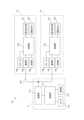
図1は、給湯装置10の構成を示す図である。 FIG. 1 is a diagram showing the configuration of a
給湯装置10は、給湯器11と、リモートコントローラ12、13を備えている。給湯器11は、ガスを燃料として湯を供給するガス給湯器である。給湯器11により生成された湯は、給湯口11aにそれぞれ接続された配管を介して、台所の蛇口や、浴槽、カラン等に供給される。給湯器11が、床暖房機能や、浴室暖房機能およびパネルヒータによる部屋暖房機能を備える場合、これら暖房機能を実現する機器に対して、給湯器11から湯が供給される。 The
給湯装置10は、カラン等に湯を供給する給湯機能の他、ふろ機能として、浴槽にお湯を張る湯張り機能と、浴槽内に湯が張られた後にその湯を保温する保温機能と、浴槽内の湯を追い焚きする追い焚き機能と、浴槽内にお湯を足す足し湯機能と、浴槽内に水を足す足し水機能とを備える。湯張り機能とそれに続く保温機能とによりふろ自動機能が構成される。ふろ自動機能が、湯張り機能のみにより構成される場合もある。 The hot
リモートコントローラ12、13は、給湯器11に接続され、給湯装置10の各機能について種々の設定を行うために用いられる。リモートコントローラ12、13は、それぞれ、操作表示部121、131と、運転ボタン122、132とを備える。 The
操作表示部121、131は、たとえば、タッチパネルであり、操作用のオブジェクトを含む画面を表示するとともに、当該オブジェクトに対する操作を受け付ける。操作者は、操作表示部121、131に表示された画面上でオブジェクトへタッチ操作を行うことにより、給湯機能、ふろ機能、暖房機能等について、任意の設定操作や運転操作を行うことができる。 The
リモートコントローラ12、13が運転オフモード(カラン等の給湯栓が開かれて基準流量以上の通水が発生したとしても給湯器11が給湯運転を行わない状態)にあるとき、操作表示部121、131は消灯状態にあり、当該操作表示部121、131へのタッチ操作は受け付けられない。運転ボタン122、132が操作され、運転オンモード(カラン等の給湯栓が開かれて基準流量以上の通水が発生したときに給湯器11が給湯運転を行える状態)になると、操作表示部121、131が点灯して給湯機能、ふろ機能、暖房機能等のための画面が表示され、当該画面上でのタッチ操作が受け付け可能となる。 When the
リモートコントローラ12、13には、音声を入出力するための音声入出力口12a、13aが設けられている。 The
リモートコントローラ12は、浴室に設置され、リモートコントローラ13は、キッチン等に設置される。以下、浴室に設置されるリモートコントローラ12を、「浴室リモコン12」と称し、キッチン等に設置されるリモートコントローラ13を、「台所リモコン13」と称する。 The
なお、給湯装置10は、宅内および宅外から携帯端末装置によって遠隔制御可能であってもよい。この場合、台所リモコン13は、無線通信により、宅内に設置されたルータと接続され、ルータおよび外部通信網(たとえば、インタネット)を介して、当該遠隔制御を行うための管理サーバと通信可能になる。携帯端末装置に入力された制御情報は、携帯端末装置から管理サーバに送信され、管理サーバから台所リモコン13に送信される。こうして、台所リモコン13に制御情報が設定され、制御情報に応じた制御が実行される。 Note that the
図2は、給湯器11、浴室リモコン12および台所リモコン13の回路ブロックを示す図である。 FIG. 2 is a diagram showing circuit blocks of the
給湯器11は、制御部111と、記憶部112と、通信部113と、センサ群114とを備える。
制御部111は、CPU(Central Processing Unit)を備え、記憶部112に記憶された制御プログラムに従って、給湯器11内の各部の制御を行う。記憶部112は、メモリを備え、制御プログラムを記憶するとともに、制御処理時のワーク領域として用いられる。 The
通信部113は、制御部111からの制御に従って、浴室リモコン12および台所リモコン13と通信を行う。通信部113は、浴室リモコン12の通信部125および台所リモコン13の通信部135と2芯通信線L10によって接続されている。 The
センサ群114は、給湯口11aに繋がる配管を流れる湯の温度を検出する温度センサ、配管を流れる湯の流量を検出する流量センサ、給湯装置10が接続された浴槽の水位を検出する水位センサ等の各種センサを備える。制御部111は、これらセンサ群114からの検出信号に基づいて、湯の供給等の制御を行う。 The
浴室リモコン12は、上述の操作表示部121および運転ボタン122の他、制御部123と、記憶部124と、通信部125と、スピーカ126とを備える。 The bathroom
制御部123は、CPUを備え、記憶部124に記憶された制御プログラムに従って所定の制御を行う。記憶部124は、メモリを備え、制御プログラムを記憶するとともに、制御処理時のワーク領域として用いられる。 The
通信部125は、制御部123からの制御に従って、給湯器11と通信を行う。通信部125は、給湯器11の通信部113および台所リモコン13の通信部135と2芯通信線L10によって接続されている。 The
スピーカ126は、制御部123からの制御に従って、所定の音声を、音声入出力口12aを介して出力する。 The
台所リモコン13は、上述の操作表示部131および運転ボタン132の他、制御部133と、記憶部134と、通信部135と、スピーカ136とを備える。 The kitchen
制御部133は、CPUを備え、記憶部134に記憶された制御プログラムに従って所定の制御を行う。記憶部134は、メモリを備え、制御プログラムを記憶するとともに、制御処理時のワーク領域として用いられる。 The
通信部135は、制御部133からの制御に従って、給湯器11と通信を行う。通信部135は、給湯器11の通信部113および浴室リモコン12の通信部125と2芯通信線L10によって接続されている。 The
スピーカ136は、制御部133からの制御に従って、所定の音声を、音声入出力口13aを介して出力する。 The
本実施形態では、浴室リモコン12および台所リモコン13の操作表示部121、131での給湯器11に係る操作、たとえば、給湯機能、ふろ機能、暖房機能等のための操作が、階層選択方式により行われる。以下、浴室リモコン12での操作について説明するが、台所リモコン13での操作も同様なものとなる。 In this embodiment, operations related to the
図3(a)、(b)は、給湯装置10が運転オンモードのときに浴室リモコン12の操作表示部121に表示されるメニュー画面200を示す図である。 FIGS. 3A and 3B are diagrams showing a
メニュー画面200は、ふろ機能に係る操作のためのふろトップ画面210と、暖房機能に係る操作のための暖房トップ画面220と、その他の2つの機能に係る操作のための2つのトップ画面230、240とが重ね合された構成である。各トップ画面210~240は、それぞれの機能における最上位の階層画面である。各トップ画面210~240には、それぞれ切替え用のタブ210a~240aが操作表示部121上に現れるように設けられ、これらタブ210a~240aがタッチ操作されることにより、操作表示部121上に現れるトップ画面210~240が切り替わる。たとえば、給湯装置10が運転オンモードになったときには、図3(a)に示すふろトップ画面210が操作表示部121に現れる。この状態から、たとえば、暖房トップ画面220のタブ220aがタッチ操作されると、図3(b)に示す暖房トップ画面220が操作表示部121に現れる。なお、タブ210a~240aは、操作表示部121の画面が下位の階層画面に移行してもそのまま残る。 The
図3(a)に示すように、ふろトップ画面210には、4つのオブジェクトとして、ふろ自動ボタンB11と、追い焚きボタンB12と、足し湯ボタンB13と、足し水ボタンB14とが、左右に並ぶように設けられる。上述の通り、ふろ機能には、ふろ自動機能、追い焚き機能、足し湯機能および足し水機能が含まれる。ふろ自動ボタンB11は、ふろ自動機能を選択するためのボタンであり、追い焚きボタンB12は、追い焚き機能を選択するボタンであり、足し湯ボタンB13は、足し湯機能を選択するためのボタンであり、足し水ボタンB14は、足し水機能を選択するためのボタンである。4つのボタンB11、B12、B13、B14の大きさは同じである。 As shown in FIG. 3(a), on the
図3(b)に示すように、暖房トップ画面220には、3つのオブジェクトとして、浴室暖房ボタンB21と、床暖房ボタンB22と、部屋暖房ボタンB23とが、左右に並ぶように設けられる。上述の通り、暖房機能には、浴室暖房機能、床暖房機能および部屋暖房機能が含まれる。浴室暖房ボタンB21は、浴室暖房機能を選択するためのボタンであり、床暖房ボタンB22は、床暖房機能を選択するボタンであり、部屋暖房ボタンB23は、部屋暖房機能を選択するためのボタンである。3つのボタンB21、B22、B23の大きさは同じである。 As shown in FIG. 3(b), the
次に、メニュー画面200が表示された状態から階層選択方式により行われる給湯器11に係る操作の具体例について説明する。 Next, a specific example of an operation related to the
まず、ふろ自動機能を開始させた後にふろ温度を設定する場合の操作と、その際の操作表示部121の画面遷移について説明する。 First, the operation for setting the bath temperature after starting the automatic bath function and the screen transition of the
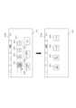
図4(a)は、操作表示部121の画面が、ふろトップ画面210から詳細設定画面211に遷移する様子を示す図であり、図4(b)は、操作表示部121の画面が、詳細設定画面211から温度設定画面212に遷移する様子を示す図である。 FIG. 4(a) is a diagram showing how the screen of the
図4(a)を参照して、ふろ自動機能の運転を開始させる場合、ユーザは、操作表示部121にふろトップ画面210が表示されている状態において、ふろ自動ボタンB11をタッチ操作する。ふろ自動ボタンB11の色が、操作されたことを示す色に変わった後に、画面がふろトップ画面210から詳細設定画面211に遷移する。詳細設定画面211は、ふろ自動ボタンB11に割り当てられた下位の階層画面である。また、ふろ自動ボタンB11が操作されることにより、ふろ自動機能の運転が開始され、浴槽内に湯が張られる。 Referring to FIG. 4A, when starting the operation of the automatic bath function, the user touches the automatic bath button B11 while the
詳細設定画面211には、3つのオブジェクトとして、ふろ温度設定ボタンB15、ふろ湯量設定ボタンB16および停止ボタンB17が、左右に並ぶように設けられる。3つのボタンB15、B16、B17の大きさは同じである。ふろ温度設定ボタンB15は、ふろの湯の温度(ふろ温度)を設定するためのボタンであり、ふろ湯量設定ボタンB16は、ふろの湯の量(ふろ湯量)を設定するためのボタンであり、停止ボタンB17は、ふろ自動機能の運転を停止させるためのボタンである。 The
また、詳細設定画面211には、上記3つのボタンB15~B17の上方に、ふろトップ画面210において詳細設定画面211へ移行させるために操作されたふろ自動ボタンB11と、ふろトップ画面210において操作されていない追い焚きボタンB12、足し湯ボタンB13および足し水ボタンB14とが、ふろトップ画面210のときと同じレイアウト(左右に配列)で設けられる。ただし、これらボタンB11~B14には、ふろトップ画面210に表示されていたときの機能が割り当てられない。 Further, on the
ここで、ふろ自動ボタンB11は、ふろトップ画面210に表示されるときよりも小さく表示される。さらに、ふろ自動ボタンB11は、追い焚きボタンB12、足し湯ボタンB13および足し水ボタンB14よりもサイズが大きくされ、且つボタンB12、B13、B14と色が変えられる。なお、ふろ自動ボタンB11は、追い焚きボタンB12、足し湯ボタンB13および足し水ボタンB14よりもサイズが大きくされるのみとされてもよいし、色が変えられるのみとされてもよい。 Here, the bath automatic button B11 is displayed smaller than when displayed on the
さらに、詳細設定画面211には、ふろトップ画面210で操作されたふろ自動ボタンB11の表示領域を含む範囲に操作領域R11が設定される。ここでは、ふろ自動ボタンB11、追い焚きボタンB12、足し湯ボタンB13および足し水ボタンB14からなるオブジェクト群の表示領域よりも少し広い範囲に操作領域R11が設定される。操作領域R11は、画面を戻す操作に利用される。 Further, on the
次に、図4(b)を参照して、ユーザは、ふろ温度を設定する場合、操作表示部121に詳細設定画面211が表示されている状態において、ふろ温度設定ボタンB15をタッチ操作する。ふろ温度設定ボタンB15の色が、操作されたことを示す色に変わった後に、画面が詳細設定画面211から温度設定画面212に遷移する。温度設定画面212は、ふろ温度設定ボタンB15に割り当てられた下位の階層画面である。 Next, referring to FIG. 4B, when setting the bath temperature, the user touches the bath temperature setting button B15 while the
温度設定画面212には、ふろ温度表示部D11の隣に、1つのオブジェクトとして、温度変更ボタンB18が設けられる。温度変更ボタンB18は、ふろ温度を昇降させるためのボタンであり、温度を上げるボタンと温度を下げるボタンとからなる。ふろ温度表示部D11は、温度変更ボタンB18により変更(設定)されたふろ温度を表示する。 On the
また、温度設定画面212には、温度変更ボタンB18とふろ温度表示部D11の上方に、詳細設定画面211において温度設定画面212へ移行させるために操作されたふろ温度設定ボタンB15と、詳細設定画面211において操作されていないふろ湯量設定ボタンB16および停止ボタンB17とが、詳細設定画面211のときと同じレイアウト(左右に配列)で設けられる。さらに、温度設定画面212には、上記3つのボタンB15~B17の上方に、ふろトップ画面210において詳細設定画面211へ移行させるために操作されたふろ自動ボタンB11と、ふろトップ画面210において操作されていない追い焚きボタンB12、足し湯ボタンB13および足し水ボタンB14とが、ふろトップ画面210のときと同じレイアウト(左右に配列)で設けられる。即ち、温度設定画面212には、2つ上位階層のふろトップ画面210に含まれていた4つのボタンB11~B14と、1つ上位階層の詳細設定画面211に含まれていた3つのボタンB15~B17と、この温度設定画面212の1つのボタンB18とが、上下に階層順に並べられる。ただし、上記のボタンB11~B14には、ふろトップ画面210に表示されていたときの機能が割り当てられず、上記のボタンB15~B17には、詳細設定画面211に表示されていたときの機能が割り当てられない。 In addition, on the
ここで、ふろ温度設定ボタンB15は、詳細設定画面211に表示されるときよりも小さく表示され、ふろ自動ボタンB11は、ふろトップ画面210に表示されるときよりも小さく且つふろ温度設定ボタンB15よりも小さく表示される。また、ふろ温度設定ボタンB15は、ふろ湯量設定ボタンB16および停止ボタンB17よりもサイズが大きくされ、且つボタンB16、B17と色が変えられる。同様に、ふろ自動ボタンB11は、追い焚きボタンB12、足し湯ボタンB13および足し水ボタンB14よりもサイズが大きくされ、且つボタンB12、B13、B14と色が変えられる。なお、ふろ温度設定ボタンB15は、ふろ湯量設定ボタンB16および停止ボタンB17よりもサイズが大きくされるのみとされてもよいし、色が変えられるのみとされてもよい。同様に、ふろ自動ボタンB11は、追い焚きボタンB12、足し湯ボタンB13および足し水ボタンB14よりもサイズが大きくされるのみとされてもよいし、色が変えられるのみとされてもよい。 Here, the bath temperature setting button B15 is displayed smaller than when displayed on the
さらに、温度設定画面212には、詳細設定画面211で操作されたふろ温度設定ボタンB15の表示領域を含む範囲に操作領域R12が設定される。ここでは、ふろ温度設定ボタンB15、ふろ湯量設定ボタンB16および停止ボタンB17からなるオブジェクト群の表示領域よりも少し広い範囲に操作領域R12が設定される。同様に、ふろトップ画面210で操作されたふろ自動ボタンB11の表示領域を含む範囲に操作領域R13が設定される。ここでは、ふろ自動ボタンB11、追い焚きボタンB12、足し湯ボタンB13および足し水ボタンB14からなるオブジェクト群の表示領域よりも少し広い範囲に操作領域R13が設定される。操作領域R12、R13は、画面を戻す操作に利用される。 Further, on the
ユーザは、温度設定画面212上において、温度変更ボタンB18を操作し、ふろ温度を所望の温度に設定する。 The user operates the temperature change button B18 on the
なお、ふろトップ画面210において、追い焚きボタンB12、足し湯ボタンB13または足し水ボタンB14がタッチ操作された場合も、これらボタンに割り当てられた、1つ以上のオブジェクトを含む下位の階層画面が表示される。また、詳細設定画面211において、ふろ湯量設定ボタンB16がタッチ操作された場合も、このボタンに割り当てられた、1つ以上のオブジェクトを含む下位の階層画面が表示される。 Furthermore, when the reheating button B12, refilling water button B13, or refilling water button B14 is touched on the
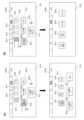
図5は、詳細設定画面211において、画面を戻す操作が行われたときの操作表示部121の画面遷移を示す図である。 FIG. 5 is a diagram showing screen transitions on the
操作表示部121に詳細設定画面211が表示されている状態において、画面をふろトップ画面210に戻す場合、ユーザは、図5に示すように、操作領域R11内の位置、即ち、ふろ自動ボタンB11を含むオブジェクト群の位置でフリック操作を行う。これにより、操作表示部121の画面が、詳細設定画面211からふろトップ画面210に戻される。 To return the screen to the
図6(a)、(b)は、温度設定画面212において、画面を戻す操作が行われたときの操作表示部121の画面遷移を示す図である。 FIGS. 6A and 6B are diagrams showing screen transitions on the
操作表示部121に温度設定画面212が表示されている状態において、画面を詳細設定画面211に戻す場合、ユーザは、図6(a)に示すように、操作領域R12内の位置、即ち、ふろ温度設定ボタンB15を含むオブジェクト群の位置でフリック操作を行う。これにより、操作表示部121の画面が、温度設定画面212から詳細設定画面211に戻される。一方、画面をふろトップ画面210に戻す場合、ユーザは、図6(b)に示すように、操作領域R13内の位置、即ち、ふろ自動ボタンB11を含むオブジェクト群の位置でフリック操作を行う。これにより、操作表示部121の画面が、温度設定画面212からふろトップ画面210に戻される。 When returning the screen to the
なお、画面を戻す操作は、操作領域R11、R12、R13内でのフリック操作に限られず、他のタッチ操作、たとえば、タップ操作であってもよい。 Note that the operation for returning the screen is not limited to a flick operation within the operation areas R11, R12, and R13, and may be another touch operation, such as a tap operation.
次に、浴室暖房機能の一つである浴室暖房の運転を行う場合の操作と、その際の操作表示部121の画面遷移について説明する。浴室暖房の運転は、浴室の暖房を行う運転である。この他、浴室暖房機能には、浴室の乾燥を行う浴室乾燥、浴室の換気を行う浴室換気、浴室に涼風を供給する浴室涼風の各運転が含まれる。 Next, the operation for operating bathroom heating, which is one of the bathroom heating functions, and the screen transitions of the
図7(a)は、操作表示部121の画面が、暖房トップ画面220から運転選択画面221に遷移する様子を示す図であり、図7(b)は、操作表示部121の画面が、運転選択画面221から詳細設定画面222に遷移する様子を示す図である。 FIG. 7(a) is a diagram showing how the screen of the
図7(a)を参照して、浴室暖房の運転を行う場合、ユーザは、操作表示部121に暖房トップ画面220が表示されている状態において、浴室暖房ボタンB21をタッチ操作する。浴室暖房ボタンB21の色が、操作されたことを示す色に変わった後に、画面が暖房トップ画面220から運転選択画面221に遷移する。運転選択画面221は、浴室暖房ボタンB21に割り当てられた下位の階層画面である。 Referring to FIG. 7A, when operating the bathroom heating, the user touches the bathroom heating button B21 while the
運転選択画面221には、4つのオブジェクトとして、乾燥ボタンB24、換気ボタンB25、涼風ボタンB26および暖房ボタンB27が、左右に並ぶように設けられる。4つのボタンB24、B25、B26、B27の大きさは同じである。乾燥ボタンB24は、浴室乾燥の運転のためのボタンであり、換気ボタンB25は、浴室換気の運転のためのボタンであり、涼風ボタンB26は、浴室涼風の運転のためのボタンであり、暖房ボタンB27は、浴室暖房の運転のためのボタンである。 On the
また、運転選択画面221には、上記4つの運転のボタンB24~B27の上方に、暖房トップ画面220において運転選択画面221へ移行させるために操作された浴室暖房ボタンB21と、暖房トップ画面220において操作されていない床暖房ボタンB22および部屋暖房ボタンB23とが、暖房トップ画面220のときと同じレイアウト(左右に配列)で設けられる。ただし、これらボタンB21~B23には、暖房トップ画面220に表示されていたときの機能が割り当てられない。 In addition, on the
ここで、浴室暖房ボタンB21は、暖房トップ画面220に表示されるときよりも小さく表示される。さらに、浴室暖房ボタンB21は、床暖房ボタンB22および部屋暖房ボタンB23よりもサイズが大きくされ、且つボタンB22、B23と色が変えられる。なお、浴室暖房ボタンB21は、床暖房ボタンB22および部屋暖房ボタンB23よりもサイズが大きくされるのみとされてもよいし、色が変えられるのみとされてもよい。 Here, the bathroom heating button B21 is displayed smaller than when displayed on the
さらに、運転選択画面221には、暖房トップ画面220で操作された浴室暖房ボタンB21の表示領域を含む範囲に操作領域R21が設定される。ここでは、浴室暖房ボタンB21、床暖房ボタンB22および部屋暖房ボタンB23からなるオブジェクト群の表示領域よりも少し広い範囲に操作領域R21が設定される。操作領域R21は、画面を戻す操作に利用される。 Further, on the
次に、図7(b)を参照して、ユーザは、操作表示部121に運転選択画面221が表示されている状態において、暖房ボタンB27をタッチ操作する。暖房ボタンB27の色が、操作されたことを示す色に変わった後に、画面が運転選択画面221から詳細設定画面222に遷移する。詳細設定画面222は、暖房ボタンB27に割り当てられた下位の階層画面である。また、暖房ボタンB27が操作されることにより、浴室暖房の運転が開始され、浴室暖房機能を実現する機器である浴室暖房機から浴室内に暖房のための温風が供給される。 Next, referring to FIG. 7(b), the user touches the heating button B27 while the
詳細設定画面222には、5つのオブジェクトとして、風向設定ボタンB28、温度設定ボタンB29、時間変更ボタンB30、強弱切替ボタンB31および停止ボタンB32が、左右に並ぶように設けられる。風向設定ボタンB28は、温風の方向を設定するためのボタンであり、温度設定ボタンB29は、温風の温度を設定するためのボタンである。時間変更ボタンB30は、運転時間を増減させるためのボタンであり、時間を増やすボタンと時間を減らすボタンとからなる。強弱変更ボタンは、浴室暖房機のヒータの強弱を切り替えるためのボタンであり、強ボタンと弱ボタンとからなる。停止ボタンB32は、浴室暖房の運転を停止させるためのボタンである。また、詳細設定画面222には、温度設定ボタンB29と時間変更ボタンB30との間に、残りの運転時間を表示する残時間表示部D21が設けられる。 The
さらに、詳細設定画面222には、上記5つのボタンB28~B32と残時間表示部D21の上方に、運転選択画面221において詳細設定画面222へ移行させるために操作された暖房ボタンB27と、運転選択画面221において操作されていない乾燥ボタンB24、換気ボタンB25および涼風ボタンB26とが、運転選択画面221のときと同じレイアウト(左右に配列)で設けられる。さらに、詳細設定画面222には、上記4つのボタンB24~B27の上方に、暖房トップ画面220において運転選択画面221へ移行させるために操作された浴室暖房ボタンB21と、暖房トップ画面220において操作されていない床暖房ボタンB22および部屋暖房ボタンB23とが、暖房トップ画面220のときと同じレイアウト(左右に配列)で設けられる。即ち、詳細設定画面222には、2つ上位階層の暖房トップ画面220に含まれていた3つのボタンB21~B23と、1つ上位階層の運転選択画面221に含まれていた4つのボタンB24~B27と、この詳細設定画面222の5つのボタンB28~B32とが、上下に階層順に並べられる。ただし、上記のボタンB21~B23には、暖房トップ画面220に表示されていたときの機能が割り当てられず、上記のボタンB24~B27には、運転選択画面221に表示されていたときの機能が割り当てられない。 Further, on the
ここで、暖房ボタンB27は、運転選択画面221に表示されるときよりも小さく表示され、浴室暖房ボタンB21は、暖房トップ画面220に表示されるときよりも小さく且つ暖房ボタンB27よりも小さく表示される。また、暖房ボタンB27は、乾燥ボタンB24、換気ボタンB25および涼風ボタンB26よりもサイズが大きくされ、且つボタンB24、B25、B26と色が変えられる。同様に、浴室暖房ボタンB21は、床暖房ボタンB22および部屋暖房ボタンB23よりもサイズが大きくされ、且つボタンB23、B23と色が変えられる。なお、暖房ボタンB27は、乾燥ボタンB24、換気ボタンB25および涼風ボタンB26よりもサイズが大きくされるのみとされてもよいし、色が変えられるのみとされてもよい。同様に、浴室暖房ボタンB21は、床暖房ボタンB22および部屋暖房ボタンB23よりもサイズが大きくされるのみとされてもよいし、色が変えられるのみとされてもよい。 Here, the heating button B27 is displayed smaller than when displayed on the
さらに、詳細設定画面222には、運転選択画面221で操作された暖房ボタンB27の表示領域を含む範囲に操作領域R22が設定される。ここでは、暖房ボタンB27、乾燥ボタンB24、換気ボタンB25および涼風ボタンB26からなるオブジェクト群の表示領域よりも少し広い範囲に操作領域R22が設定される。同様に、暖房トップ画面220で操作された浴室暖房ボタンB21の表示領域を含む範囲に操作領域R23が設定される。ここでは、浴室暖房ボタンB21、床暖房ボタンB22および部屋暖房ボタンB23からなるオブジェクト群の表示領域よりも少し広い範囲に操作領域R23が設定される。操作領域R22、R23は、画面を戻す操作に利用される。 Further, on the
浴室暖房の運転中に、温風の風向や温度の設定、運転時間やヒータの強弱の変更を行いたい場合、ユーザは、風向設定ボタンB28、温度設定ボタンB29、時間変更ボタンB30または強弱切替ボタンB31をタッチ操作する。浴室暖房の運転を終了したい場合には、ユーザは、停止ボタンB32をタッチ操作する。なお、風向設定ボタンB28および温度設定ボタンB29には、それぞれ風向および温度を設定するための下位の階層画面が割り当てられており、これらボタンがタッチ操作されると、操作表示部121の画面が詳細設定画面222から下位の階層画面に移行する。 If the user wants to set the direction and temperature of hot air, change the operating time, or change the strength of the heater while the bathroom heater is running, the user can press the wind direction setting button B28, temperature setting button B29, time change button B30, or strength switching button. Touch B31. If the user wants to end the bathroom heating operation, the user touches the stop button B32. Note that the wind direction setting button B28 and the temperature setting button B29 are assigned lower hierarchical screens for setting the wind direction and temperature, respectively, and when these buttons are touched, the screen on the
なお、暖房トップ画面220において、床暖房ボタンB22または部屋暖房ボタンB23がタッチ操作された場合も、これらボタンに割り当てられた、1つ以上のオブジェクトを含む下位の階層画面が表示される。また、運転選択画面221において、乾燥ボタンB24、換気ボタンB25または涼風ボタンB26がタッチ操作された場合も、これらボタンに割り当てられた、1つ以上のオブジェクトを含む下位の階層画面が表示される。 Note that when the floor heating button B22 or the room heating button B23 is touched on the
図8は、運転選択画面221において、画面を戻す操作が行われたときの操作表示部121の画面遷移を示す図である。 FIG. 8 is a diagram showing screen transitions on the
操作表示部121に運転選択画面221が表示されている状態において、画面を暖房トップ画面220に戻す場合、ユーザは、図8に示すように、操作領域R21内の位置、即ち、浴室暖房ボタンB21を含むオブジェクト群の位置でフリック操作を行う。これにより、操作表示部121の画面が、運転選択画面221から暖房トップ画面220に戻される。 When the
図9(a)、(b)は、詳細設定画面222において、画面を戻す操作が行われたときの操作表示部121の画面遷移を示す図である。 FIGS. 9A and 9B are diagrams showing screen transitions on the
操作表示部121に詳細設定画面222が表示されている状態において、画面を運転選択画面221に戻す場合、ユーザは、図9(a)に示すように、操作領域R22内の位置、即ち、暖房ボタンB27を含むオブジェクト群の位置でフリック操作を行う。これにより、操作表示部121の画面が、詳細設定画面222から運転選択画面221に戻される。一方、画面を暖房トップ画面220に戻す場合、ユーザは、図9(b)に示すように、操作領域R23内の位置、即ち、浴室暖房ボタンB21を含むオブジェクト群の位置でフリック操作を行う。これにより、操作表示部121の画面が、詳細設定画面222から暖房トップ画面220に戻される。 When returning the screen to the
なお、画面を戻す操作は、操作領域R21、R22、R23内でのフリック操作に限られず、他のタッチ操作、たとえば、タップ操作であってもよい。 Note that the operation for returning the screen is not limited to a flick operation within the operation areas R21, R22, and R23, and may be another touch operation, such as a tap operation.
図10は、操作表示部121に表示された最上位の階層画面上において操作が行われたときの制御部123による処理を示すフローチャートである。図11は、操作表示部121に表示された下位の階層画面上において操作が行われたときの制御部123による処理を示すフローチャートである。 FIG. 10 is a flowchart showing processing by the
図10を参照して、制御部123は、最上位の階層画面(ふろトップ画面210、暖房トップ画面220等)を操作表示部121に表示させると、最上位の階層画面に含まれたオブジェクトに対してタッチ操作がなされたか否かを監視する(S101)。何れかのオブジェクトにタッチ操作がなされた場合(S101:YES)、制御部123は、そのオブジェクトが下位の階層画面の割当があるオブジェクト(風呂自動ボタンB11、浴室暖房ボタンB21等)であれば(S102:YES)、操作表示部121の画面を、割り当てられた下位の階層画面(詳細設定画面211、運転選択画面221等)に移行させる(S103)。下位の階層画面には、少なくとも一つのオブジェクト(ふろ温度設定ボタンB15、暖房ボタンB27等)が含まれる。制御部123は、この下位の階層画面において、最上位の階層画面において操作されたオブジェクト(ふろ自動ボタンB11、浴室暖房ボタンB21等)を、最上位の階層画面で操作されていないオブジェクト(追い焚きボタンB12、床暖房ボタンB22等)とともに表示させる。 Referring to FIG. 10, when the
一方、S102において、タッチ操作されたオブジェクトが下位の階層画面の割当があるオブジェクトでないと判定した場合(S102:NO)、制御部123は、そのオブジェクトに割り当てられた制御を行う(S104)。S101の処理に戻り、新たなオブジェクトのタッチ操作が監視される。 On the other hand, if it is determined in S102 that the touched object is not an object to which a lower hierarchical screen is assigned (S102: NO), the
操作表示部121に下位の階層画面が表示されると、図11の処理が行われる。 When the lower hierarchical screen is displayed on the
図11を参照して、制御部123は、下位の階層画面(詳細設定画面211、運転選択画面221等)に含まれたオブジェクトに対してタッチ操作がなされたか否か、および、下位の階層画面に対して画面を戻す操作、即ち、戻し操作の操作領域(操作領域R11、R21等)に対するフリック操作がなされたか否かを監視する(S201、S202)。何れかのオブジェクトにタッチ操作がなされた場合(S201:YES)、制御部123は、そのオブジェクトが下位の階層画面の割当があるオブジェクト(ふろ温度設定ボタンB15、暖房ボタンB27等)であれば(S203:YES)、操作表示部121の画面を、割り当てられた1つ下位の階層画面(温度設定画面212、詳細設定画面222等)に移行させる(S204)。1つ下位の階層画面には、少なくとも1つのオブジェクト(温度変更ボタンB18、風向設定ボタンB28等)が含まれる。制御部123は、この下位の階層画面において、その1つ上位の階層画面において操作されたオブジェクト(ふろ温度設定ボタンB15、暖房ボタンB27等)を、この階層画面で操作されていないオブジェクト(ふろ湯量設定ボタンB16、乾燥ボタンB24等)とともに表示させる。また、制御部123は、この下位の階層画面において、2つ上位の階層画面(最上位の階層画面)において操作されたオブジェクト(ふろ自動ボタンB11、浴室暖房ボタンB21等)を、この階層画面で操作されていないオブジェクト(追い焚きボタンB12、床暖房ボタンB22等)とともに表示させる。その後、再び、図11の処理が開始される。 Referring to FIG. 11, the
一方、S203において、タッチ操作されたオブジェクトが下位の階層画面の割当があるオブジェクトでないと判定した場合(S203:NO)、制御部123は、そのオブジェクトに割り当てられた制御を行う(S205)。S201の処理に戻り、新たなオブジェクトのタッチ操作が監視される。 On the other hand, if it is determined in S203 that the touched object is not an object assigned to a lower hierarchical screen (S203: NO), the
S202において、戻し操作がなされたと判定した場合(S202:YES)、制御部123は、操作表示部121の画面を、戻し操作に応じた上位の階層画面に戻す(S206)。即ち、最上位よりも1つ下位あるいは2つ以上下位の階層画面において、最上位の階層画面に含まれているオブジェクトに対応する操作領域へのフリック操作がなされた場合は、操作表示部121の画面が最上位の階層画面へ戻される(図5、図6(b)、図8、図9(b)参照)。また、最上位よりも2つ以上下位の階層画面において、その階層画面より上位であって最上位でない階層画面に含まれているオブジェクトに対応する操作領域へのフリック操作がなされた場合は、操作表示部121の画面が、そのオブジェクトが含まれた上位の階層画面へ戻される(図6(a)、図9(a)参照)。 In S202, if it is determined that the return operation has been performed (S202: YES), the
操作表示部121に最上位の階層画面が表示されれば、図9の処理が開始され、操作表示部121に最上位でない上位の階層画面が表示されれば、再び図10の処理が開始される。 If the highest level hierarchical screen is displayed on the
なお、台所リモコン13においても、操作表示部131に最上位の階層画面が表示された場合に、制御部133により、図9および図10の処理が実行される。 Note that in the kitchen
<実施形態の効果>
以上、本実施形態によれば、以下の効果が奏され得る。<Effects of embodiment>
As described above, according to this embodiment, the following effects can be achieved.
図4(a)、(b)あるいは図7(a)、(b)に示すように、操作表示部121、131の画面が下位の階層画面へと移行した場合に、この下位の階層画面には、当該階層画面のオブジェクトと一緒に、その上位の階層画面において操作がなされたオブジェクトが表示される。これにより、ユーザは、下位の階層画面へと操作を進めたときに、現在、全体の階層の中のどの位置の階層において操作を行っているかが分かり易くなるので、その階層の画面での操作を進めやすくなったり所望の階層へ画面を戻しやすくなったりする。よって、ユーザは、一連の階層選択方式の操作を容易に行うことが可能となる。 As shown in FIGS. 4(a), (b) or 7(a), (b), when the screen of the
また、上位の階層画面において操作がなされたオブジェクトは、その上位の階層画面で表示されるときよりも小さく表示されるので、下位の階層画面のオブジェクトと区別がつきやすく、また、表示スペースが大きくとられにくい。 In addition, objects operated on higher-level hierarchical screens are displayed smaller than when displayed on higher-level hierarchical screens, making them easier to distinguish from objects on lower-level hierarchical screens, and requiring a larger display space. Hard to catch.
さらに、下位の階層画面には、その上位の階層画面において操作がなされたオブジェクトのみならず、操作がなされなかったオブジェクトも表示され、この際には、操作がなされたオブジェクトは、操作がなされなかったオブジェクトと大きさや色が変えられるので、ユーザは、上位の階層画面で操作されたオブジェクトを把握しやすくなる。 Furthermore, the lower hierarchical screen displays not only the objects that were operated on in the upper hierarchical screen, but also the objects that were not operated on. Since the size and color of the objects can be changed, it becomes easier for the user to understand which objects have been operated on the upper hierarchical screen.
さらに、図5、図6(a)、(b)あるいは図8、図9(a)、(b)に示すように、ユーザは、下位の階層画面において、画面を戻す操作を行うことにより、操作表示部121の画面を、上位の階層画面に戻すことができる。特に、上位の階層画面で操作がなされたオブジェクトの表示領域が含まれる操作領域が設定され、当該操作領域に対するタッチ操作(フリック操作)が画面を戻す操作とされているので、ユーザは、戻す操作を直感的に行えやすく、操作が容易になる。 Furthermore, as shown in FIGS. 5, 6(a), (b) or FIGS. 8, 9(a), (b), by performing an operation to return the screen on the lower hierarchical screen, the user can The screen of the
さらに、図4(b)あるいは図7(b)に示すように、最上位の階層画面より2つ下位の階層画面では、その階層画面より1つ上位の階層画面で操作されたオブジェクトと、最上位の階層画面で操作されたオブジェクトと、その2つ下位の階層画面のオブジェクトとが階層順に並べられるので、どのような操作をたどって現在の階層画面へ進んできたかが把握されやすくなり、一連の階層選択方式の操作が、一層容易になる。 Furthermore, as shown in FIG. 4(b) or FIG. 7(b), in the hierarchical screen two levels below the highest hierarchical screen, the objects operated on the hierarchical screen one level above the hierarchical screen and the Objects operated on the upper hierarchical screen and objects on the two lower hierarchical screens are arranged in hierarchical order, making it easier to understand what operations have been followed to reach the current hierarchical screen, and The operation of the hierarchy selection method becomes easier.
さらに、図6(a)、(b)または図9(a)、(b)に示すように、2つ下位の階層画面では、最上位の階層画面で操作されたオブジェクトが含まれる操作領域に対してタッチ操作が行われることにより、操作表示部121、131の画面が、一気に最上位の階層画面に戻されるので、素早い画面の戻しが可能となり、操作性が向上する。 Furthermore, as shown in FIGS. 6(a), (b) or 9(a), (b), in the hierarchical screen two levels below, the operation area containing the object operated on the highest hierarchical screen is By performing a touch operation on the screen, the screens of the
以上、本発明の実施形態について説明したが、本発明は、上記実施形態に限定されるものではなく、また、本発明の適用例も、上記実施形態の他に、種々の変更が可能である。 Although the embodiments of the present invention have been described above, the present invention is not limited to the above embodiments, and the application examples of the present invention can also be modified in various ways other than the above embodiments. .
たとえば、上記実施形態では、下位の階層画面に、上位の階層画面で操作されたオブジェクトと上位の階層画面で操作されていないオブジェクトの双方が表示された。しかしながら、下位の階層画面に、上位の階層画面で操作されたオブジェクトのみが表示されてもよい。この場合、画面を戻す操作のために、そのオブジェクトの表示領域と同じ範囲あるいは少し広い範囲の操作領域が設定されるとよい。 For example, in the above embodiment, both objects operated on the upper hierarchical screen and objects not operated on the upper hierarchical screen are displayed on the lower hierarchical screen. However, only the objects operated on the upper hierarchical screen may be displayed on the lower hierarchical screen. In this case, for the operation to return the screen, it is preferable to set an operation area that is the same as or slightly wider than the display area of the object.
たとえば、図12(a)の例では、詳細設定画面211に、ふろトップ画面210において操作されたふろ自動ボタンB11のみが表示される。また、詳細設定画面211には、ふろ自動ボタンB11の表示領域より少し広い範囲の操作領域R11が設定される。 For example, in the example of FIG. 12A, only the bath automatic button B11 operated on the
同様に、図12(b)の例では、温度設定画面212に、詳細設定画面211において操作されたふろ温度設定ボタンB15と、ふろトップ画面210において操作されたふろ自動ボタンB11とのみが表示される。また、温度設定画面212には、ふろ温度設定ボタンB15の表示領域より少し広い範囲の操作領域R12と、ふろ自動ボタンB11の表示領域より少し広い範囲の操作領域R13が設定される。 Similarly, in the example of FIG. 12(b), only the bath temperature setting button B15 operated on the
同様に、図12(c)の例では、運転選択画面221に、暖房トップ画面220において操作された浴室暖房ボタンB21のみが表示される。また、運転選択画面221には、浴室暖房ボタンB21の表示領域より少し広い範囲の操作領域R21が設定される。 Similarly, in the example of FIG. 12C, only the bathroom heating button B21 operated on the
同様に、図12(d)の例では、詳細設定画面222に、運転選択画面221において操作された暖房ボタンB27と、暖房トップ画面220において操作された浴室暖房ボタンB21とのみが表示される。また、詳細設定画面222には、暖房ボタンB27の表示領域より少し広い範囲の操作領域R22と、浴室暖房ボタンB21の表示領域より少し広い範囲の操作領域R23が設定される。 Similarly, in the example of FIG. 12(d), only the heating button B27 operated on the
また、上記実施形態では、下位の階層画面(詳細設定画面211、運転選択画面221等)において、その階層画面のオブジェクト(ボタンB15~B17、ボタンB24~B27等)が左右方向に並び、それらオブジェクトと、上位の階層画面(ふろトップ画面210、暖房トップ画面220等)に含まれたオブジェクト(ボタンB11~B14、ボタンB21~B23等)とが上下方向に並んだ。しかしながら、下位の階層画面において、その階層画面のオブジェクトが上下方向に並び、それらオブジェクトと、上位の階層画面に含まれたオブジェクトとが左右方向に並んでもよい。 Furthermore, in the above embodiment, in the lower hierarchical screen (
さらに、上記実施形態では、下位の階層画面において、上位の階層画面において操作されたオブジェクトの表示領域が含まれる操作領域が設定され、この操作領域へのタッチ操作、即ちフリック操作がなされると、操作表示部121の画面が、その上位の階層画面に戻された。しかしながら、画面を戻す動作は、上記のものに限られず、たとえば、下位の階層画面の任意の位置においてフリック操作が行われたときに、所定時間当たりのフリック操作の回数分だけ上位の階層画面に戻されるような構成が採られてもよい。 Furthermore, in the above embodiment, an operation area that includes the display area of the object operated on the upper layer screen is set on the lower layer screen, and when a touch operation, that is, a flick operation is performed on this operation area, The screen of the
さらに、上記実施形態では、浴室リモコン12および台所リモコン13の操作表示部121、131での給湯器11に係る操作が、階層選択方式により行われる。しかしながら、浴室リモコン12および台所リモコン13の操作表示部121、131のうちの何れか一方において、給湯器11に係る操作が階層選択方式により行われるようにされてもよい。 Further, in the embodiment described above, the operations related to the
さらに、リモートコントローラの個数は2つに限られるものではなく、1つまたは3つ以上であってもよい。 Furthermore, the number of remote controllers is not limited to two, and may be one or three or more.
さらに、給湯装置10は、ガス燃料を用いるものに限らず、オイルを燃料とする給湯装置であってもよい。給湯装置10は、貯留タンクを用いた貯留式のものであってもよく、燃料電池等の発電ユニットをさらに備えた構成であってもよい。 Furthermore, the
この他、本発明の実施形態は、特許請求の範囲に記載の範囲で適宜種々の変更可能である。 In addition, the embodiments of the present invention can be modified in various ways within the scope of the claims.
10 給湯装置
11 給湯器(給湯部)
12 浴室リモコン
121 操作表示部
123 制御部
13 台所リモコン
131 操作表示部
133 制御部
210 ふろトップ画面(第1の階層画面)
211 詳細設定画面(第2の階層画面)
212 温度設定画面(第3の階層画面)
220 暖房トップ画面(第1の階層画面)
221 運転選択画面(第2の階層画面)
222 詳細設定画面(第3の階層画面)
B11 ふろ自動ボタン(第1のオブジェクト)
B12 追い焚きボタン(第1のオブジェクト)
B13 足し湯ボタン(第1のオブジェクト)
B14 足し水ボタン(第1のオブジェクト)
B15 ふろ温度設定ボタン(第2のオブジェクト)
B16 ふろ湯量設定ボタン(第2のオブジェクト)
B17 停止ボタン(第2のオブジェクト)
B18 温度変更ボタン(第3のオブジェクト)
B21 浴室暖房ボタン(第1のオブジェクト)
B22 床暖房ボタン(第1のオブジェクト)
B23 部屋暖房ボタン(第1のオブジェクト)
B24 乾燥ボタン(第1のオブジェクト)
B25 換気ボタン(第2のオブジェクト)
B26 涼風ボタン(第2のオブジェクト)
B27 暖房ボタン(第2のオブジェクト)
B28 風向設定ボタン(第3のオブジェクト)
B29 温度設定ボタン(第3のオブジェクト)
B30 時間変更ボタン(第3のオブジェクト)
B31 強弱切替ボタン(第3のオブジェクト)
B32 停止ボタン(第3のオブジェクト)
R11 操作領域
R12 操作領域
R13 操作領域
R21 操作領域
R22 操作領域
R23 操作領域10
12 Bathroom
211 Detailed settings screen (second layer screen)
212 Temperature setting screen (third layer screen)
220 Heating top screen (first layer screen)
221 Operation selection screen (second layer screen)
222 Detailed settings screen (third layer screen)
B11 Bath automatic button (first object)
B12 Reheat button (first object)
B13 Hot water button (first object)
B14 Add water button (first object)
B15 Bath temperature setting button (second object)
B16 Bath water amount setting button (second object)
B17 Stop button (second object)
B18 Temperature change button (third object)
B21 Bathroom heating button (first object)
B22 Floor heating button (first object)
B23 Room heating button (first object)
B24 Drying button (first object)
B25 Ventilation button (second object)
B26 Cool breeze button (second object)
B27 Heating button (second object)
B28 Wind direction setting button (third object)
B29 Temperature setting button (third object)
B30 Time change button (third object)
B31 Strength switching button (third object)
B32 Stop button (third object)
R11 Operation area R12 Operation area R13 Operation area R21 Operation area R22 Operation area R23 Operation area
Claims (3)
Translated fromJapanese前記操作表示部を制御する制御部を備え、
前記制御部は、
少なくとも一つの第1のオブジェクトを含む第1の階層画面を前記操作表示部に表示させ、
前記第1の階層画面上で一つの前記第1のオブジェクトが操作されると、前記操作表示部の画面を、操作された前記第1のオブジェクトに割り当てられた、少なくとも一つの第2のオブジェクトを含む第2の階層画面に移行させ、
前記第2の階層画面へ移行させるために操作された前記第1のオブジェクトを前記第2の階層画面に含ませ、
前記第2の階層画面上で一つの前記第2のオブジェクトが操作されると、前記操作表示部の画面を、操作された前記第2のオブジェクトに割り当てられた、少なくとも一つの第3のオブジェクトを含む第3の階層画面に移行させ、
前記第2の階層画面へ移行させるために操作された前記第1のオブジェクトと前記第3の階層画面へ移行させるために操作された前記第2のオブジェクトとを前記第3の階層画面に含ませ、
前記第3の階層画面において、操作された前記第1のオブジェクトの表示領域を含む範囲に、画面を戻す第1の戻し操作の操作領域を設定し、操作された前記第2のオブジェクトの表示領域を含む範囲に、画面を戻す第2の戻し操作の操作領域を設定し、
前記第1の戻し操作の操作領域に対して操作がなされたときに前記操作表示部の画面を前記第1の階層画面に戻し、前記第2の戻し操作の操作領域に対して操作がなされたときに前記操作表示部の画面を前記第2の階層画面に戻す、
ことを特徴とする給湯装置。A hot water supply device comprising a hot water supply unit that performs a hot water supply operation, and an operation display unit that displays an object and receives an operation on the object, and in which an operation related to the hot water supply unit on the operation display unit is performed in a hierarchy selection method,
comprising a control unit that controls the operation display unit,
The control unit includes:
displaying a first hierarchical screen including at least one first object on the operation display unit;
When one of the first objects is operated on the first hierarchical screen, the screen of the operation display section is changed to display at least one second object assigned to the operated first object. Move to the second layer screen containing
including the first object operated to move to the second hierarchical screen in the second hierarchical screen;
When one of the second objects is operated on the second hierarchical screen, the screen of the operation display section is changed to display at least one third object assigned to the operated second object. Move to the third layer screen that includes
The third hierarchical screen includes the first object operated to transition to the second hierarchical screen and the second object operated to transition to the third hierarchical screen. ,
In the third hierarchical screen, an operation area for a first return operation for returning the screen is set to a range that includes the display area of the operated firstobject , and the operation area of the operated secondobject is set. Set the operation area for the second return operation to return the screen to the range that includes the display area,
When an operation is performed on the operation area for the first return operation, the screen of the operation display unit is returned to the first hierarchical screen, and an operation is performed on the operation area for the second return operation. when returning the screen of the operation display unit to the second hierarchical screen;
A water heater characterized by:
前記第3の階層画面には、前記第1のオブジェクト、前記第2のオブジェクトおよび前記第3のオブジェクトが、階層順に並べられる、
ことを特徴とする給湯装置。The water heater according to claim 1,
On the third hierarchical screen, the first object, the second object, and the third object are arranged in hierarchical order.
A water heater characterized by:
前記第3の階層画面には、前記第1のオブジェクトが前記第1の階層画面に表示されるときよりも小さく表示され、前記第2のオブジェクトが前記第2の階層画面に表示されるときよりも小さく表示される、
ことを特徴とする給湯装置。The water heater according to claim 1 or 2,
On the third hierarchical screen, the first object is displayed smaller than when displayed on the first hierarchical screen, and the second object is displayed smaller than when displayed on the second hierarchical screen. is also displayed smaller,
A water heater characterized by:
Priority Applications (1)
| Application Number | Priority Date | Filing Date | Title |
|---|---|---|---|
| JP2019155087AJP7385108B2 (en) | 2019-08-27 | 2019-08-27 | water heater |
Applications Claiming Priority (1)
| Application Number | Priority Date | Filing Date | Title |
|---|---|---|---|
| JP2019155087AJP7385108B2 (en) | 2019-08-27 | 2019-08-27 | water heater |
Publications (2)
| Publication Number | Publication Date |
|---|---|
| JP2021033793A JP2021033793A (en) | 2021-03-01 |
| JP7385108B2true JP7385108B2 (en) | 2023-11-22 |
Family
ID=74676610
Family Applications (1)
| Application Number | Title | Priority Date | Filing Date |
|---|---|---|---|
| JP2019155087AActiveJP7385108B2 (en) | 2019-08-27 | 2019-08-27 | water heater |
Country Status (1)
| Country | Link |
|---|---|
| JP (1) | JP7385108B2 (en) |
Citations (4)
| Publication number | Priority date | Publication date | Assignee | Title |
|---|---|---|---|---|
| JP2004183972A (en) | 2002-12-03 | 2004-07-02 | Toto Ltd | Hot-water supply apparatus |
| JP2010113420A (en) | 2008-11-04 | 2010-05-20 | Canon Inc | Information processing apparatus, information processing method, and program |
| JP2014120176A (en) | 2012-12-17 | 2014-06-30 | Samsung Electronics Co Ltd | Display apparatus, and method of providing ui thereof |
| JP2014142074A (en) | 2013-01-22 | 2014-08-07 | Corona Corp | Remote controller of hot water storage type water heater |
- 2019
- 2019-08-27JPJP2019155087Apatent/JP7385108B2/enactiveActive
Patent Citations (4)
| Publication number | Priority date | Publication date | Assignee | Title |
|---|---|---|---|---|
| JP2004183972A (en) | 2002-12-03 | 2004-07-02 | Toto Ltd | Hot-water supply apparatus |
| JP2010113420A (en) | 2008-11-04 | 2010-05-20 | Canon Inc | Information processing apparatus, information processing method, and program |
| JP2014120176A (en) | 2012-12-17 | 2014-06-30 | Samsung Electronics Co Ltd | Display apparatus, and method of providing ui thereof |
| JP2014142074A (en) | 2013-01-22 | 2014-08-07 | Corona Corp | Remote controller of hot water storage type water heater |
Also Published As
| Publication number | Publication date |
|---|---|
| JP2021033793A (en) | 2021-03-01 |
Similar Documents
| Publication | Publication Date | Title |
|---|---|---|
| JP6202082B2 (en) | Setting value change device | |
| JP5663711B1 (en) | Information terminal control method and program | |
| US10067661B2 (en) | Method for controlling information apparatus and computer-readable recording medium | |
| US10326607B2 (en) | Method for controlling information apparatus and computer-readable recording medium | |
| KR101266078B1 (en) | Home electric power management system | |
| JP5739002B2 (en) | Communication device and communication system | |
| CN106322770A (en) | Bathroom mirror, water heater and control method and system of water heater | |
| CN112368512A (en) | Touch screen lighting system controller | |
| JP7385108B2 (en) | water heater | |
| JP2016224666A (en) | Input control program and input device | |
| JP2019205120A (en) | Remote operation system and program for hot water equipment | |
| JP6049494B2 (en) | Mobile device | |
| JP2009250570A (en) | Remote control for heat pump type water heater | |
| CN111676654B (en) | Control method of household appliances | |
| JP2012112596A (en) | Remote control apparatus | |
| CN115325596B (en) | Multi-split control method and device and multi-split | |
| JP2016018397A (en) | Device management apparatus, device management method, and display device | |
| JP6068186B2 (en) | Equipment operation device | |
| JP7742534B2 (en) | Control system and display method | |
| JP2017032252A (en) | Hot water supply remote controller | |
| TWI714514B (en) | Node name diversified hierarchical group management device and setting method thereof | |
| JP7521234B2 (en) | Operating device | |
| JP2024047912A (en) | Terminal device and computer program | |
| JP2004353917A (en) | Hot water use remote control | |
| WO2017212614A1 (en) | Ac controller and air conditioning control management system |
Legal Events
| Date | Code | Title | Description |
|---|---|---|---|
| A621 | Written request for application examination | Free format text:JAPANESE INTERMEDIATE CODE: A621 Effective date:20220705 | |
| A977 | Report on retrieval | Free format text:JAPANESE INTERMEDIATE CODE: A971007 Effective date:20230320 | |
| A131 | Notification of reasons for refusal | Free format text:JAPANESE INTERMEDIATE CODE: A131 Effective date:20230328 | |
| A521 | Request for written amendment filed | Free format text:JAPANESE INTERMEDIATE CODE: A523 Effective date:20230526 | |
| A131 | Notification of reasons for refusal | Free format text:JAPANESE INTERMEDIATE CODE: A131 Effective date:20230711 | |
| A521 | Request for written amendment filed | Free format text:JAPANESE INTERMEDIATE CODE: A523 Effective date:20230907 | |
| TRDD | Decision of grant or rejection written | ||
| A01 | Written decision to grant a patent or to grant a registration (utility model) | Free format text:JAPANESE INTERMEDIATE CODE: A01 Effective date:20231010 | |
| A61 | First payment of annual fees (during grant procedure) | Free format text:JAPANESE INTERMEDIATE CODE: A61 Effective date:20231023 | |
| R150 | Certificate of patent or registration of utility model | Ref document number:7385108 Country of ref document:JP Free format text:JAPANESE INTERMEDIATE CODE: R150 |