JP7383516B2 - Heart valve docking devices and systems - Google Patents
Heart valve docking devices and systemsDownload PDFInfo
- Publication number
- JP7383516B2 JP7383516B2JP2020027120AJP2020027120AJP7383516B2JP 7383516 B2JP7383516 B2JP 7383516B2JP 2020027120 AJP2020027120 AJP 2020027120AJP 2020027120 AJP2020027120 AJP 2020027120AJP 7383516 B2JP7383516 B2JP 7383516B2
- Authority
- JP
- Japan
- Prior art keywords
- docking station
- valve
- expandable
- valve seat
- retention
- Prior art date
- Legal status (The legal status is an assumption and is not a legal conclusion. Google has not performed a legal analysis and makes no representation as to the accuracy of the status listed.)
- Active
Links
- 238000003032molecular dockingMethods0.000titleclaimsdescription707
- 210000003709heart valveAnatomy0.000titledescription59
- 238000007789sealingMethods0.000claimsdescription163
- 230000014759maintenance of locationEffects0.000claimsdescription111
- 210000002216heartAnatomy0.000claimsdescription99
- 239000008280bloodSubstances0.000claimsdescription66
- 210000004369bloodAnatomy0.000claimsdescription66
- 239000006260foamSubstances0.000claimsdescription30
- 239000002184metalSubstances0.000claimsdescription30
- 229910052751metalInorganic materials0.000claimsdescription30
- 239000004744fabricSubstances0.000claimsdescription21
- 230000036772blood pressureEffects0.000claimsdescription11
- 210000001147pulmonary arteryAnatomy0.000description156
- 239000000463materialSubstances0.000description50
- 230000017531blood circulationEffects0.000description35
- 238000000034methodMethods0.000description23
- 230000007246mechanismEffects0.000description17
- 210000003484anatomyAnatomy0.000description16
- 238000010586diagramMethods0.000description16
- 239000012530fluidSubstances0.000description16
- 210000005241right ventricleAnatomy0.000description16
- 238000002513implantationMethods0.000description13
- 230000002262irrigationEffects0.000description11
- 238000003973irrigationMethods0.000description11
- 230000000670limiting effectEffects0.000description10
- 210000005245right atriumAnatomy0.000description8
- 238000001356surgical procedureMethods0.000description8
- 229910001000nickel titaniumInorganic materials0.000description7
- HLXZNVUGXRDIFK-UHFFFAOYSA-Nnickel titaniumChemical compound[Ti].[Ti].[Ti].[Ti].[Ti].[Ti].[Ti].[Ti].[Ti].[Ti].[Ti].[Ni].[Ni].[Ni].[Ni].[Ni].[Ni].[Ni].[Ni].[Ni].[Ni].[Ni].[Ni].[Ni].[Ni]HLXZNVUGXRDIFK-UHFFFAOYSA-N0.000description7
- 210000003102pulmonary valveAnatomy0.000description7
- 238000004873anchoringMethods0.000description6
- 210000005240left ventricleAnatomy0.000description6
- 239000007769metal materialSubstances0.000description6
- 150000002739metalsChemical class0.000description6
- 239000007787solidSubstances0.000description6
- 210000001765aortic valveAnatomy0.000description5
- 208000037265diseases, disorders, signs and symptomsDiseases0.000description5
- 239000006261foam materialSubstances0.000description5
- 229920000642polymerPolymers0.000description5
- 230000002792vascularEffects0.000description5
- 210000001631vena cava inferiorAnatomy0.000description5
- 230000002861ventricularEffects0.000description5
- 208000023281Fallot tetralogyDiseases0.000description4
- 201000003005Tetralogy of FallotDiseases0.000description4
- 210000000709aortaAnatomy0.000description4
- 210000004204blood vesselAnatomy0.000description4
- 230000002950deficientEffects0.000description4
- 201000010099diseaseDiseases0.000description4
- 230000006870functionEffects0.000description4
- 230000002401inhibitory effectEffects0.000description4
- 230000000717retained effectEffects0.000description4
- 210000005166vasculatureAnatomy0.000description4
- 210000002620vena cava superiorAnatomy0.000description4
- 206010067171RegurgitationDiseases0.000description3
- 229910045601alloyInorganic materials0.000description3
- 239000000956alloySubstances0.000description3
- 230000036961partial effectEffects0.000description3
- 239000012781shape memory materialSubstances0.000description3
- 210000001519tissueAnatomy0.000description3
- 210000000591tricuspid valveAnatomy0.000description3
- 229920005830Polyurethane FoamPolymers0.000description2
- FAPWRFPIFSIZLT-UHFFFAOYSA-MSodium chlorideChemical compound[Na+].[Cl-]FAPWRFPIFSIZLT-UHFFFAOYSA-M0.000description2
- 208000001910Ventricular Heart Septal DefectsDiseases0.000description2
- 230000005856abnormalityEffects0.000description2
- 210000001367arteryAnatomy0.000description2
- 239000012620biological materialSubstances0.000description2
- 230000008859changeEffects0.000description2
- 238000004140cleaningMethods0.000description2
- 238000000576coating methodMethods0.000description2
- 210000003748coronary sinusAnatomy0.000description2
- 230000000694effectsEffects0.000description2
- 210000003191femoral veinAnatomy0.000description2
- 239000007943implantSubstances0.000description2
- 238000003780insertionMethods0.000description2
- 230000037431insertionEffects0.000description2
- 210000005246left atriumAnatomy0.000description2
- 230000004048modificationEffects0.000description2
- 238000012986modificationMethods0.000description2
- 210000004165myocardiumAnatomy0.000description2
- 210000003516pericardiumAnatomy0.000description2
- 229920000728polyesterPolymers0.000description2
- 239000011496polyurethane foamSubstances0.000description2
- 208000014903transposition of the great arteriesDiseases0.000description2
- 201000003130ventricular septal defectDiseases0.000description2
- 208000035473Communicable diseaseDiseases0.000description1
- 208000027205Congenital diseaseDiseases0.000description1
- 235000004035Cryptotaenia japonicaNutrition0.000description1
- 206010020880HypertrophyDiseases0.000description1
- 208000031481Pathologic ConstrictionDiseases0.000description1
- 208000006396Pulmonary artery stenosisDiseases0.000description1
- 208000000924Right ventricular hypertrophyDiseases0.000description1
- 102000007641Trefoil FactorsHuman genes0.000description1
- 235000015724Trifolium pratenseNutrition0.000description1
- 238000013459approachMethods0.000description1
- 238000005452bendingMethods0.000description1
- 230000036770blood supplyEffects0.000description1
- 230000000747cardiac effectEffects0.000description1
- 210000000748cardiovascular systemAnatomy0.000description1
- 230000004087circulationEffects0.000description1
- 239000011248coating agentSubstances0.000description1
- 230000006835compressionEffects0.000description1
- 238000007906compressionMethods0.000description1
- 230000001010compromised effectEffects0.000description1
- 208000028831congenital heart diseaseDiseases0.000description1
- 230000008878couplingEffects0.000description1
- 238000010168coupling processMethods0.000description1
- 238000005859coupling reactionMethods0.000description1
- 230000007547defectEffects0.000description1
- 238000011257definitive treatmentMethods0.000description1
- 230000010339dilationEffects0.000description1
- 208000035475disorderDiseases0.000description1
- 230000002526effect on cardiovascular systemEffects0.000description1
- 229910000701elgiloys (Co-Cr-Ni Alloy)Inorganic materials0.000description1
- 230000008030eliminationEffects0.000description1
- 238000003379elimination reactionMethods0.000description1
- 208000018578heart valve diseaseDiseases0.000description1
- 208000015181infectious diseaseDiseases0.000description1
- 208000027866inflammatory diseaseDiseases0.000description1
- 230000002757inflammatory effectEffects0.000description1
- 239000007788liquidSubstances0.000description1
- 210000004072lungAnatomy0.000description1
- 230000007257malfunctionEffects0.000description1
- 210000004115mitral valveAnatomy0.000description1
- 210000003205muscleAnatomy0.000description1
- RVTZCBVAJQQJTK-UHFFFAOYSA-Noxygen(2-);zirconium(4+)Chemical compound[O-2].[O-2].[Zr+4]RVTZCBVAJQQJTK-UHFFFAOYSA-N0.000description1
- 229920000515polycarbonatePolymers0.000description1
- 239000004417polycarbonateSubstances0.000description1
- 230000002685pulmonary effectEffects0.000description1
- 230000002829reductive effectEffects0.000description1
- 230000008439repair processEffects0.000description1
- 239000011780sodium chlorideSubstances0.000description1
- 230000006641stabilisationEffects0.000description1
- 238000011105stabilizationMethods0.000description1
- 230000000087stabilizing effectEffects0.000description1
- 239000010935stainless steelSubstances0.000description1
- 229910001220stainless steelInorganic materials0.000description1
- 230000036262stenosisEffects0.000description1
- 208000037804stenosisDiseases0.000description1
- 239000013589supplementSubstances0.000description1
- 229920002994synthetic fiberPolymers0.000description1
- 230000008719thickeningEffects0.000description1
- 210000003813thumbAnatomy0.000description1
- 238000012546transferMethods0.000description1
- 230000007704transitionEffects0.000description1
- 210000003462veinAnatomy0.000description1
Images


Classifications
- A—HUMAN NECESSITIES
- A61—MEDICAL OR VETERINARY SCIENCE; HYGIENE
- A61F—FILTERS IMPLANTABLE INTO BLOOD VESSELS; PROSTHESES; DEVICES PROVIDING PATENCY TO, OR PREVENTING COLLAPSING OF, TUBULAR STRUCTURES OF THE BODY, e.g. STENTS; ORTHOPAEDIC, NURSING OR CONTRACEPTIVE DEVICES; FOMENTATION; TREATMENT OR PROTECTION OF EYES OR EARS; BANDAGES, DRESSINGS OR ABSORBENT PADS; FIRST-AID KITS
- A61F2/00—Filters implantable into blood vessels; Prostheses, i.e. artificial substitutes or replacements for parts of the body; Appliances for connecting them with the body; Devices providing patency to, or preventing collapsing of, tubular structures of the body, e.g. stents
- A61F2/02—Prostheses implantable into the body
- A61F2/24—Heart valves ; Vascular valves, e.g. venous valves; Heart implants, e.g. passive devices for improving the function of the native valve or the heart muscle; Transmyocardial revascularisation [TMR] devices; Valves implantable in the body
- A61F2/2409—Support rings therefor, e.g. for connecting valves to tissue
- A—HUMAN NECESSITIES
- A61—MEDICAL OR VETERINARY SCIENCE; HYGIENE
- A61F—FILTERS IMPLANTABLE INTO BLOOD VESSELS; PROSTHESES; DEVICES PROVIDING PATENCY TO, OR PREVENTING COLLAPSING OF, TUBULAR STRUCTURES OF THE BODY, e.g. STENTS; ORTHOPAEDIC, NURSING OR CONTRACEPTIVE DEVICES; FOMENTATION; TREATMENT OR PROTECTION OF EYES OR EARS; BANDAGES, DRESSINGS OR ABSORBENT PADS; FIRST-AID KITS
- A61F2/00—Filters implantable into blood vessels; Prostheses, i.e. artificial substitutes or replacements for parts of the body; Appliances for connecting them with the body; Devices providing patency to, or preventing collapsing of, tubular structures of the body, e.g. stents
- A61F2/02—Prostheses implantable into the body
- A61F2/24—Heart valves ; Vascular valves, e.g. venous valves; Heart implants, e.g. passive devices for improving the function of the native valve or the heart muscle; Transmyocardial revascularisation [TMR] devices; Valves implantable in the body
- A61F2/2412—Heart valves ; Vascular valves, e.g. venous valves; Heart implants, e.g. passive devices for improving the function of the native valve or the heart muscle; Transmyocardial revascularisation [TMR] devices; Valves implantable in the body with soft flexible valve members, e.g. tissue valves shaped like natural valves
- A61F2/2418—Scaffolds therefor, e.g. support stents
- A—HUMAN NECESSITIES
- A61—MEDICAL OR VETERINARY SCIENCE; HYGIENE
- A61F—FILTERS IMPLANTABLE INTO BLOOD VESSELS; PROSTHESES; DEVICES PROVIDING PATENCY TO, OR PREVENTING COLLAPSING OF, TUBULAR STRUCTURES OF THE BODY, e.g. STENTS; ORTHOPAEDIC, NURSING OR CONTRACEPTIVE DEVICES; FOMENTATION; TREATMENT OR PROTECTION OF EYES OR EARS; BANDAGES, DRESSINGS OR ABSORBENT PADS; FIRST-AID KITS
- A61F2/00—Filters implantable into blood vessels; Prostheses, i.e. artificial substitutes or replacements for parts of the body; Appliances for connecting them with the body; Devices providing patency to, or preventing collapsing of, tubular structures of the body, e.g. stents
- A61F2/02—Prostheses implantable into the body
- A61F2/24—Heart valves ; Vascular valves, e.g. venous valves; Heart implants, e.g. passive devices for improving the function of the native valve or the heart muscle; Transmyocardial revascularisation [TMR] devices; Valves implantable in the body
- A61F2/2427—Devices for manipulating or deploying heart valves during implantation
- A—HUMAN NECESSITIES
- A61—MEDICAL OR VETERINARY SCIENCE; HYGIENE
- A61F—FILTERS IMPLANTABLE INTO BLOOD VESSELS; PROSTHESES; DEVICES PROVIDING PATENCY TO, OR PREVENTING COLLAPSING OF, TUBULAR STRUCTURES OF THE BODY, e.g. STENTS; ORTHOPAEDIC, NURSING OR CONTRACEPTIVE DEVICES; FOMENTATION; TREATMENT OR PROTECTION OF EYES OR EARS; BANDAGES, DRESSINGS OR ABSORBENT PADS; FIRST-AID KITS
- A61F2/00—Filters implantable into blood vessels; Prostheses, i.e. artificial substitutes or replacements for parts of the body; Appliances for connecting them with the body; Devices providing patency to, or preventing collapsing of, tubular structures of the body, e.g. stents
- A61F2/02—Prostheses implantable into the body
- A61F2/24—Heart valves ; Vascular valves, e.g. venous valves; Heart implants, e.g. passive devices for improving the function of the native valve or the heart muscle; Transmyocardial revascularisation [TMR] devices; Valves implantable in the body
- A61F2/2427—Devices for manipulating or deploying heart valves during implantation
- A61F2/2436—Deployment by retracting a sheath
- A—HUMAN NECESSITIES
- A61—MEDICAL OR VETERINARY SCIENCE; HYGIENE
- A61F—FILTERS IMPLANTABLE INTO BLOOD VESSELS; PROSTHESES; DEVICES PROVIDING PATENCY TO, OR PREVENTING COLLAPSING OF, TUBULAR STRUCTURES OF THE BODY, e.g. STENTS; ORTHOPAEDIC, NURSING OR CONTRACEPTIVE DEVICES; FOMENTATION; TREATMENT OR PROTECTION OF EYES OR EARS; BANDAGES, DRESSINGS OR ABSORBENT PADS; FIRST-AID KITS
- A61F2/00—Filters implantable into blood vessels; Prostheses, i.e. artificial substitutes or replacements for parts of the body; Appliances for connecting them with the body; Devices providing patency to, or preventing collapsing of, tubular structures of the body, e.g. stents
- A61F2/02—Prostheses implantable into the body
- A61F2/24—Heart valves ; Vascular valves, e.g. venous valves; Heart implants, e.g. passive devices for improving the function of the native valve or the heart muscle; Transmyocardial revascularisation [TMR] devices; Valves implantable in the body
- A61F2/2442—Annuloplasty rings or inserts for correcting the valve shape; Implants for improving the function of a native heart valve
- A—HUMAN NECESSITIES
- A61—MEDICAL OR VETERINARY SCIENCE; HYGIENE
- A61F—FILTERS IMPLANTABLE INTO BLOOD VESSELS; PROSTHESES; DEVICES PROVIDING PATENCY TO, OR PREVENTING COLLAPSING OF, TUBULAR STRUCTURES OF THE BODY, e.g. STENTS; ORTHOPAEDIC, NURSING OR CONTRACEPTIVE DEVICES; FOMENTATION; TREATMENT OR PROTECTION OF EYES OR EARS; BANDAGES, DRESSINGS OR ABSORBENT PADS; FIRST-AID KITS
- A61F2/00—Filters implantable into blood vessels; Prostheses, i.e. artificial substitutes or replacements for parts of the body; Appliances for connecting them with the body; Devices providing patency to, or preventing collapsing of, tubular structures of the body, e.g. stents
- A61F2/02—Prostheses implantable into the body
- A61F2/24—Heart valves ; Vascular valves, e.g. venous valves; Heart implants, e.g. passive devices for improving the function of the native valve or the heart muscle; Transmyocardial revascularisation [TMR] devices; Valves implantable in the body
- A61F2/2475—Venous valves
- A—HUMAN NECESSITIES
- A61—MEDICAL OR VETERINARY SCIENCE; HYGIENE
- A61F—FILTERS IMPLANTABLE INTO BLOOD VESSELS; PROSTHESES; DEVICES PROVIDING PATENCY TO, OR PREVENTING COLLAPSING OF, TUBULAR STRUCTURES OF THE BODY, e.g. STENTS; ORTHOPAEDIC, NURSING OR CONTRACEPTIVE DEVICES; FOMENTATION; TREATMENT OR PROTECTION OF EYES OR EARS; BANDAGES, DRESSINGS OR ABSORBENT PADS; FIRST-AID KITS
- A61F2/00—Filters implantable into blood vessels; Prostheses, i.e. artificial substitutes or replacements for parts of the body; Appliances for connecting them with the body; Devices providing patency to, or preventing collapsing of, tubular structures of the body, e.g. stents
- A61F2/95—Instruments specially adapted for placement or removal of stents or stent-grafts
- A61F2/9517—Instruments specially adapted for placement or removal of stents or stent-grafts handle assemblies therefor
- A—HUMAN NECESSITIES
- A61—MEDICAL OR VETERINARY SCIENCE; HYGIENE
- A61F—FILTERS IMPLANTABLE INTO BLOOD VESSELS; PROSTHESES; DEVICES PROVIDING PATENCY TO, OR PREVENTING COLLAPSING OF, TUBULAR STRUCTURES OF THE BODY, e.g. STENTS; ORTHOPAEDIC, NURSING OR CONTRACEPTIVE DEVICES; FOMENTATION; TREATMENT OR PROTECTION OF EYES OR EARS; BANDAGES, DRESSINGS OR ABSORBENT PADS; FIRST-AID KITS
- A61F2220/00—Fixations or connections for prostheses classified in groups A61F2/00 - A61F2/26 or A61F2/82 or A61F9/00 or A61F11/00 or subgroups thereof
- A61F2220/0008—Fixation appliances for connecting prostheses to the body
- A—HUMAN NECESSITIES
- A61—MEDICAL OR VETERINARY SCIENCE; HYGIENE
- A61F—FILTERS IMPLANTABLE INTO BLOOD VESSELS; PROSTHESES; DEVICES PROVIDING PATENCY TO, OR PREVENTING COLLAPSING OF, TUBULAR STRUCTURES OF THE BODY, e.g. STENTS; ORTHOPAEDIC, NURSING OR CONTRACEPTIVE DEVICES; FOMENTATION; TREATMENT OR PROTECTION OF EYES OR EARS; BANDAGES, DRESSINGS OR ABSORBENT PADS; FIRST-AID KITS
- A61F2220/00—Fixations or connections for prostheses classified in groups A61F2/00 - A61F2/26 or A61F2/82 or A61F9/00 or A61F11/00 or subgroups thereof
- A61F2220/0025—Connections or couplings between prosthetic parts, e.g. between modular parts; Connecting elements
- A61F2220/0075—Connections or couplings between prosthetic parts, e.g. between modular parts; Connecting elements sutured, ligatured or stitched, retained or tied with a rope, string, thread, wire or cable
- A—HUMAN NECESSITIES
- A61—MEDICAL OR VETERINARY SCIENCE; HYGIENE
- A61F—FILTERS IMPLANTABLE INTO BLOOD VESSELS; PROSTHESES; DEVICES PROVIDING PATENCY TO, OR PREVENTING COLLAPSING OF, TUBULAR STRUCTURES OF THE BODY, e.g. STENTS; ORTHOPAEDIC, NURSING OR CONTRACEPTIVE DEVICES; FOMENTATION; TREATMENT OR PROTECTION OF EYES OR EARS; BANDAGES, DRESSINGS OR ABSORBENT PADS; FIRST-AID KITS
- A61F2250/00—Special features of prostheses classified in groups A61F2/00 - A61F2/26 or A61F2/82 or A61F9/00 or A61F11/00 or subgroups thereof
- A61F2250/0058—Additional features; Implant or prostheses properties not otherwise provided for
- A61F2250/006—Additional features; Implant or prostheses properties not otherwise provided for modular
- A—HUMAN NECESSITIES
- A61—MEDICAL OR VETERINARY SCIENCE; HYGIENE
- A61F—FILTERS IMPLANTABLE INTO BLOOD VESSELS; PROSTHESES; DEVICES PROVIDING PATENCY TO, OR PREVENTING COLLAPSING OF, TUBULAR STRUCTURES OF THE BODY, e.g. STENTS; ORTHOPAEDIC, NURSING OR CONTRACEPTIVE DEVICES; FOMENTATION; TREATMENT OR PROTECTION OF EYES OR EARS; BANDAGES, DRESSINGS OR ABSORBENT PADS; FIRST-AID KITS
- A61F2250/00—Special features of prostheses classified in groups A61F2/00 - A61F2/26 or A61F2/82 or A61F9/00 or A61F11/00 or subgroups thereof
- A61F2250/0058—Additional features; Implant or prostheses properties not otherwise provided for
- A61F2250/0069—Sealing means
Landscapes
- Health & Medical Sciences (AREA)
- Cardiology (AREA)
- Engineering & Computer Science (AREA)
- Biomedical Technology (AREA)
- Life Sciences & Earth Sciences (AREA)
- Transplantation (AREA)
- Heart & Thoracic Surgery (AREA)
- Vascular Medicine (AREA)
- Oral & Maxillofacial Surgery (AREA)
- Animal Behavior & Ethology (AREA)
- General Health & Medical Sciences (AREA)
- Public Health (AREA)
- Veterinary Medicine (AREA)
- Prostheses (AREA)
- Check Valves (AREA)
- Surgical Instruments (AREA)
- External Artificial Organs (AREA)
Description
Translated fromJapanese本発明は、心臓弁に関し、特に、心臓弁、例えば経カテーテル心臓弁(「THV」)の埋込みに使用される、ドッキングステーション/ステント、送達システム、および方法に関する。 FIELD OF THE INVENTION The present invention relates to heart valves, and more particularly to docking stations/stents, delivery systems, and methods used in the implantation of heart valves, such as transcatheter heart valves ("THV").
人工心臓弁は心臓弁疾患の治療に使用することができる。天然心臓弁(大動脈弁、肺動脈弁、三尖弁、および僧帽弁)は、心臓血管系を通る適正な血液供給の前進流を保証する重要な機能に役立っている。これらの心臓弁は、先天性、炎症性、または感染性疾患によって効率が下がる場合がある。かかる疾患は、最終的に、深刻な心臓血管系の副作用または死亡につながり得る。長年、かかる障害に対する根治的治療は、開心術中に弁を外科的に修復または置換するものであった。 Artificial heart valves can be used to treat heart valve disease. Natural heart valves (aortic, pulmonary, tricuspid, and mitral) serve the important function of ensuring proper forward flow of blood supply through the cardiovascular system. These heart valves may become less efficient due to congenital, inflammatory, or infectious disease. Such diseases can ultimately lead to serious cardiovascular side effects or death. For many years, the definitive treatment for such disorders was to surgically repair or replace the valve during open heart surgery.
開心術よりも低侵襲性である方法で、可撓性カテーテルを使用して人工心臓弁を導入し埋め込む、経カテーテル的技術を使用することもできる。この技術では、人工弁を、折り曲げられた状態で可撓性カテーテルの端部部分に装着し、弁が埋込み部位に達するまで患者の血管を通して前進させることが可能である。次に、弁を装着しているバルーンを膨張させることなどによって、欠陥がある天然弁の部位で、カテーテル先端にある弁をそれが機能的サイズまで拡張させることができる。あるいは、弁は、カテーテルの遠位端にある送達シースから弁を前進させると弁がその機能的サイズまで拡張する、弾力性の自己拡張型ステントまたはフレームを有することができる。 Transcatheter techniques can also be used, in which a flexible catheter is used to introduce and implant a prosthetic heart valve in a less invasive manner than open heart surgery. In this technique, the prosthetic valve can be placed in a folded position on the end portion of a flexible catheter and advanced through the patient's blood vessel until the valve reaches the implantation site. The valve at the catheter tip can then be expanded to its functional size at the site of the defective native valve, such as by inflating a balloon mounting the valve. Alternatively, the valve can have a resilient, self-expanding stent or frame that expands the valve to its functional size upon advancement of the valve from the delivery sheath at the distal end of the catheter.
経カテーテル心臓弁(THV)は、ほとんどの天然大動脈弁の内部に配置されるように適切にサイズ決めすることができる。しかしながら、天然弁、血管、およびグラフトが大きい場合、大動脈経カテーテル弁は、大きい埋込みまたは配備部位にしっかり嵌め込むには小さすぎることがある。この場合、経カテーテル弁は、所定位置で固定されるように、天然弁または他の埋込みもしくは配備部位の内部で十分に拡張するのには大きさが足りないことがある。 Transcatheter heart valves (THVs) can be appropriately sized to be placed inside most native aortic valves. However, when native valves, vessels, and grafts are large, aortic transcatheter valves may be too small to fit securely into large implantation or deployment sites. In this case, the transcatheter valve may not be large enough to expand sufficiently within the native valve or other implantation or deployment site to lock in place.
pulmonic valveと称されることがある肺動脈弁(pulmonary valve)の置換は、著しい課題をもたらす。肺動脈の幾何学形状は患者ごとに大きく異なる場合がある。一般的に、矯正手術後の肺動脈流出路は、人工心臓弁を有効に配置するのには広すぎる。 Replacement of the pulmonary valve, sometimes referred to as the pulmonic valve, poses significant challenges. Pulmonary artery geometry can vary widely from patient to patient. Typically, the pulmonary artery outflow tract after corrective surgery is too wide for effective placement of a prosthetic heart valve.
この概要は、例を提供するためのものであり、本発明の範囲をいかなる形でも限定しようとするものではない。例えば、この概要の一例に含まれる任意の特徴は、特許請求の範囲においてその特徴を明示的に列挙しない限り、特許請求の範囲に必須ではない。本明細書は、拡張型弁のための拡張型ドッキングステーション、拡張型ドッキングステーションのためのカテーテル、およびカテーテルのためのハンドルの例示的な実施形態を開示する。ドッキングステーション、カテーテル、およびハンドルは、様々な方法で構築することができる。 This summary is for the purpose of providing an example and is not intended to limit the scope of the invention in any way. For example, any feature included in this exemplary summary is not essential to the scope of a claim unless the feature is explicitly recited in a claim. Disclosed herein are exemplary embodiments of an expandable docking station for an expandable valve, a catheter for an expandable docking station, and a handle for a catheter. Docking stations, catheters, and handles can be constructed in a variety of ways.
一実施形態では、例えば、ドッキングステーションは、弁座と、1つまたは複数の封止部分と、1つまたは複数の保定部分とを含むことができる。一実施形態では、弁座は、配備後のサイズ以上には実質的に拡張不能であることができ、即ち、弁座の直径は最大0~4mmしか増大できなくてもよい。1つまたは複数の封止部分は、弁座に接続し、弁座の径方向外側に延在することができる。1つまたは複数の封止部分は、弁座の外側に拡張し延在し、あるサイズ範囲にわたってシールを提供するように構築することができる(例えば、ある拡張サイズ範囲にわたって、および/または循環系もしくは脈管系内のあるサイズ範囲にわたって、様々な形状およびサイズの異なる血管または場所において拡張したときに、シールを提供することが可能であってもよい)。1つまたは複数の保定部分は、1つまたは複数の封止部分に接続することができる。1つまたは複数の保定部分は、配備位置でドッキングステーションを保定するように構成することができる。拡張型ドッキングステーションは、27mm~38mmの範囲にわたって拡張しシールを提供することができる。拡張型ドッキングステーションは、その長さLに沿って様々な程度に径方向外側に拡張することができる。弁座および1つまたは複数の封止部分は、弁座における拡張型弁の径方向外向きの力が1つもしくは複数の封止部分または1つもしくは複数の保定部分に移行されることを低減または防止する、アイソレータとして作用することができる。ドッキングステーションは、保定部分による保定が血圧によって強化されるように構成することができる。1つまたは複数の保定部分は、配備位置にある1つまたは複数の保定部分のうちの少なくとも1つによって加えられる力が、ドッキングステーションに作用する血圧に比例するように構成することができる。1つまたは複数の保定部分は、1つまたは複数の保定部分のうちの少なくとも1つによって加えられる力が、心臓が拡張期のときの方が心臓が収縮期のときよりも大きいように構成することができる。弁座は、縫合糸、リング、バンド、構造的構成、材料、発泡体、および他の方法で形成することができる。封止部分は、布地、ポリマー、および/または他の材料で被覆された金属フレームの一部分を含むことができる。封止部分は連続気泡発泡体を含むことができる。ドッキングステーションの一部分は血液透過性であることができ、ドッキングステーションの一部分は血液不透過性であることができる。血液不透過性であるドッキングステーションの一部分は、少なくとも弁座から少なくとも封止部分まで延在することができる。ドッキングステーションは長さ調節可能であることができる。ドッキングステーションは第1の半片を含むことができ、その中へとドッキングステーションの第2の半片が調節可能に延在して、長さを調節することができる。1つまたは複数の保定部分は、ドッキングステーションが非拘束状態のとき、1つまたは複数の封止部分の径方向外側に延在することができる。本開示の別の箇所に記載する他の特徴も含まれてもよい。 In one embodiment, for example, a docking station can include a valve seat, one or more sealing portions, and one or more retention portions. In one embodiment, the valve seat may be substantially non-expandable beyond its post-deployment size, ie, the diameter of the valve seat may only increase by a maximum of 0-4 mm. One or more sealing portions may connect to the valve seat and extend radially outwardly of the valve seat. The one or more sealing portions can be constructed to expand and extend outwardly of the valve seat and provide a seal over an extended size range (e.g., over an extended size range and/or within the circulatory system). or may be capable of providing a seal when expanded in different shapes and sizes of vessels or locations over a size range within the vasculature). One or more retaining portions can be connected to one or more sealing portions. The one or more retention portions can be configured to retain the docking station in the deployed position. The expandable docking station can extend and provide a seal over a range of 27mm to 38mm. The expandable docking station is capable of expanding radially outward along its length L to varying degrees. The valve seat and the one or more sealing portions reduce the transfer of radially outward forces of the expandable valve at the valve seat to the one or more sealing portions or the one or more retention portions. or can act as an isolator. The docking station can be configured such that retention by the retention portion is enhanced by blood pressure. The one or more retention portions may be configured such that the force applied by at least one of the one or more retention portions in the deployed position is proportional to the blood pressure acting on the docking station. The one or more retention portions are configured such that the force exerted by at least one of the one or more retention portions is greater when the heart is in diastole than when the heart is in systole. be able to. The valve seat can be formed with sutures, rings, bands, structural configurations, materials, foams, and other methods. The sealing portion can include a portion of a metal frame covered with fabric, polymer, and/or other materials. The sealing portion can include open cell foam. A portion of the docking station can be blood permeable and a portion of the docking station can be blood impermeable. A portion of the docking station that is blood impermeable may extend from at least the valve seat to at least the sealing portion. The docking station can be length adjustable. The docking station can include a first half into which a second docking station half can adjustably extend to adjust the length. The one or more retention portions may extend radially outwardly of the one or more sealing portions when the docking station is in an unrestrained state. Other features described elsewhere in this disclosure may also be included.
例示的な一実施形態では、システムは、拡張型ドッキングステーションと拡張型弁とを含むことができる。拡張型ドッキングステーションは、弁座と、1つまたは複数の封止部分と、1つまたは複数の保定部分とを含むことができる。弁座は配備後のサイズまで拡張することができる。1つまたは複数の封止部分は、弁座に接続することができ、弁座の径方向外側に拡張し延在し、ある拡張サイズ範囲にわたってシールを提供するように構築することができる。1つまたは複数の保定部分は、1つまたは複数の封止部分に接続することができる。1つまたは複数の保定部分は、配備位置でドッキングステーションを保定するように構成することができる。拡張型弁は、拡張型フレームと弁要素とを含むことができる。拡張型フレームを拡張させて、ドッキングステーションの弁座を係合することができる。弁要素は拡張型フレームに接続することができる。拡張型ドッキングステーションおよび拡張型弁は、循環系の一部分に埋め込まれたとき、循環系のその一部分に対して封止部分によって加えられる径方向外向きの力が、封止部分があるサイズ範囲内にある場合、拡張型フレームによって弁座に加えられる径方向外向きの力の1/2未満である(かつ、1/3未満、1/4未満、1/8未満、または1/10未満であり得る)ように、構成することができる。拡張型ドッキングステーションは、循環系の一部分に埋め込まれたとき、弁座の直径が、拡張型フレームによって弁座に加えられる径方向外向きの力によって、3mm超(または1mm、2mm、もしくは4mm超)は増大しないように、構成することができる。封止部分のサイズ範囲は27mm~38mmであることができる。拡張型ドッキングステーションは、循環系の一部分に埋め込まれたとき、その長さLに沿って様々な程度に径方向外側に拡張するように構成することができる。 In one exemplary embodiment, a system can include an expandable docking station and an expandable valve. The expandable docking station can include a valve seat, one or more sealing portions, and one or more retention portions. The valve seat can be expanded to its deployed size. One or more sealing portions can be connected to the valve seat and can be constructed to extend and extend radially outwardly of the valve seat to provide a seal over an extended size range. One or more retaining portions can be connected to one or more sealing portions. The one or more retention portions can be configured to retain the docking station in the deployed position. The expandable valve can include an expandable frame and a valve element. The expandable frame can be expanded to engage the valve seat of the docking station. The valve element can be connected to the expandable frame. Expandable docking stations and expandable valves, when implanted in a portion of a circulatory system, limit the radial outward force exerted by a sealing portion on that portion of the circulatory system to within the size range of the sealing portion. is less than 1/2 (and less than 1/3, less than 1/4, less than 1/8, or less than 1/10) of the radially outward force exerted on the valve seat by the expandable frame. (possible). The expandable docking station, when implanted in a portion of the circulatory system, allows the diameter of the valve seat to exceed 3 mm (or 1 mm, 2 mm, or 4 mm) due to the radially outward force exerted on the valve seat by the expandable frame. ) can be configured so that it does not increase. The size range of the sealing portion can be from 27mm to 38mm. The expandable docking station can be configured to expand radially outward to varying degrees along its length L when implanted in a portion of the circulatory system.
拡張型ドッキングステーションは、循環系の一部分に埋め込まれたとき、保定部分による保定が拡張型ドッキングステーションに対する血圧によって強化されるように構成することができる。拡張型ドッキングステーションは、循環系の一部分に埋め込まれたとき、保定部分によって加えられる力がアセンブリに作用する血圧に比例するように構成することができる。拡張型ドッキングステーションは、循環系の一部分に埋め込まれたとき、保定部分によって加えられる力が、心臓が拡張期のときの方が心臓が収縮期のときよりも大きいように構成することができる。弁座は、縫合糸、リング、バンド、構造的構成、材料、発泡体、および他の方法で形成することができる。封止部分は、布地で被覆された金属フレームの一部分を含むことができる。封止部分は連続気泡発泡体を含むことができる。ドッキングステーションの一部分は血液透過性であることができ、ドッキングステーションの一部分は血液不透過性であることができる。血液不透過性であるドッキングステーションの一部分は、少なくとも弁座から少なくとも封止部分まで延在することができる。ドッキングステーションは調節可能な全長を有することができる。ドッキングステーションは第1の半片(即ち、部分)を含むことができ、その中へとドッキングステーションの第2の半片(即ち、部分)が調節可能に延在して、全長を調節することができる。換言すれば、第2の半片/部分を第1の半片/部分に対して移動させることによって、ドッキングステーションの長さを調節することができ、第1の半片/部分は第2の半片/部分とは独立して移動させてもよい(例えば、一方の半片/部分が所定位置に残り、他方の半片/部分が移動してもよい)。第1または第2の半片/部分の一方が他方の半片/部分内部で延在し、重なり合って長さが調節された場合、第1の半片/部分および第2の半片/部分は、それら2つの重なり合いの量/長さを変えるように調節されてもよい。1つまたは複数の保定部分は、ドッキングステーションが非拘束状態のとき、1つまたは複数の封止部分の径方向外側に延在することができる。本開示の別の箇所に記載する他の特徴も含まれてもよい。 The expandable docking station can be configured such that when implanted in a portion of the circulatory system, retention by the retention portion is enhanced by blood pressure relative to the expandable docking station. The expandable docking station can be configured such that when implanted in a portion of the circulatory system, the force exerted by the retention portion is proportional to the blood pressure acting on the assembly. The expandable docking station, when implanted in a portion of the circulatory system, can be configured such that the force exerted by the retention portion is greater when the heart is in diastole than when the heart is in systole. The valve seat can be formed with sutures, rings, bands, structural configurations, materials, foams, and other methods. The sealing portion can include a portion of a metal frame covered with fabric. The sealing portion can include open cell foam. A portion of the docking station can be blood permeable and a portion of the docking station can be blood impermeable. A portion of the docking station that is blood impermeable may extend from at least the valve seat to at least the sealing portion. The docking station can have an adjustable overall length. The docking station can include a first half (i.e., section) into which a second half (i.e., section) of the docking station can adjustably extend to adjust the overall length. . In other words, the length of the docking station can be adjusted by moving the second half/section relative to the first half/section, and the first half/section (eg, one half/section may remain in place and the other half/section may be moved). If one of the first or second halves/sections extends within the other half/section and is adjusted in length by overlapping, the first half/section and the second half/section are may be adjusted to vary the amount/length of the two overlaps. The one or more retention portions may extend radially outwardly of the one or more sealing portions when the docking station is in an unrestrained state. Other features described elsewhere in this disclosure may also be included.
例示的な一実施形態では、方法は、ドッキングステーションを拡張することと、ドッキングステーション内で弁を拡張することとを含むことができる。ドッキングステーションは、ドッキングステーションの弁座が、弁座の配備後のサイズへと拡張し、封止部分が、ある封止サイズ範囲内の封止サイズへと拡張するように、拡張させることができる。拡張型弁のフレームを拡張させて、ドッキングステーションの弁座を係合することができる。封止サイズ範囲にわたる封止部分によって加えられる径方向外向きの力は、拡張型フレームを拡張した後にフレームによって弁座に加えられる径方向外向きの力の1/2未満であることができる(また、1/3未満、1/4未満、1/8未満、または1/10未満であることができる)。ドッキングステーションの弁座は、弁座の直径が、拡張型フレームによって弁座に加えられる径方向外向きの力によって、2mm超(または1mm、3mm、もしくは4mm超)は増大しないように、構成することができる。ドッキングステーションの封止サイズ範囲は27mm~38mmであることができる。弁座は、縫合糸、リング、バンド、構造的構成、材料、発泡体、および他の方法で形成することができる。本開示の別の箇所に記載する他の特徴/ステップも含まれてもよい。 In an exemplary embodiment, a method can include expanding a docking station and expanding a valve within the docking station. The docking station is expandable such that the valve seat of the docking station expands to a post-deployment size of the valve seat and the sealing portion expands to a sealing size within a sealing size range. . The frame of the expandable valve can be expanded to engage the valve seat of the docking station. The radially outward force exerted by the sealing portion over the sealing size range can be less than 1/2 of the radially outward force exerted by the frame on the valve seat after expanding the expandable frame ( It can also be less than 1/3, less than 1/4, less than 1/8, or less than 1/10). The valve seat of the docking station is configured such that the diameter of the valve seat is not increased by more than 2 mm (or more than 1 mm, 3 mm, or 4 mm) by the outward radial force applied to the valve seat by the expandable frame. be able to. The sealing size range of the docking station can be from 27mm to 38mm. The valve seat can be formed with sutures, rings, bands, structural configurations, materials, foams, and other methods. Other features/steps described elsewhere in this disclosure may also be included.
例示的な一実施形態では、システムは、拡張型ドッキングステーションと拡張型弁とを含むことができる。拡張型ドッキングステーションは、弁座と、1つまたは複数の封止部分と、1つまたは複数の保定部分とを含むことができる。弁座は配備後のサイズまで拡張することができる。1つまたは複数の封止部分は、弁座に接続し、弁座の径方向外側に延在することができる。1つまたは複数の封止部分は、弁座の外側に拡張し、あるサイズ範囲にわたってシールを提供するように構築することができる。1つまたは複数の保定部分は、1つまたは複数の封止部分に接続することができる。1つまたは複数の保定部分は、配備位置でドッキングステーションを保定するように構成することができる。拡張型弁は、拡張型フレームと弁要素とを備えることができる。拡張型フレームが拡張して、ドッキングステーションの弁座を係合することができる。弁要素は拡張型フレームに接続することができる。弁およびドッキングステーションに作用する血圧によって、配備位置での保定部分による保定を強化することができる。 In one exemplary embodiment, a system can include an expandable docking station and an expandable valve. The expandable docking station can include a valve seat, one or more sealing portions, and one or more retention portions. The valve seat can be expanded to its deployed size. One or more sealing portions may connect to the valve seat and extend radially outwardly of the valve seat. The one or more sealing portions can be constructed to extend outside the valve seat and provide a seal over a size range. One or more retaining portions can be connected to one or more sealing portions. The one or more retention portions can be configured to retain the docking station in the deployed position. The expandable valve can include an expandable frame and a valve element. The expandable frame can expand to engage the valve seat of the docking station. The valve element can be connected to the expandable frame. Blood pressure acting on the valve and docking station can enhance retention by the retention portion in the deployed position.
弁座は、拡張型弁の径方向外向きの力によって弁座が径方向外側には実質的に拡張されないように、構成することができる。封止部分のサイズ範囲は27mm~38mmであることができる。ドッキングステーションは、その長さLに沿って様々な程度に径方向外側に拡張するように構成することができる。保定部分によって加えられる力は、アセンブリに作用する血圧に比例することができる。保定部分によって加えられる力は、心臓が拡張期のときの方が心臓が収縮期のときよりも大きくなってよい。弁座は、縫合糸、リング、バンド、構造的構成、材料、発泡体、および他の方法で形成することができる。封止部分は、布地で被覆された金属フレームの一部分を含むことができる。封止部分は連続気泡発泡体または他の材料を含むことができる。ドッキングステーションの一部分は血液透過性であることができ、ドッキングステーションの一部分は血液不透過性であることができる。血液不透過性であるドッキングステーションの一部分は、少なくとも弁座から少なくとも封止部分まで延在することができる。ドッキングステーションは長さ調節可能であることができる。ドッキングステーションは第1の半片(即ち、部分)を含むことができ、その中へとドッキングステーションの第2の半片(即ち、部分)が調節可能に延在して、全長を調節することができる。換言すれば、第2の半片/部分を第1の半片/部分に対して移動させることによって、ドッキングステーションの長さを調節することができ、第1の半片/部分は第2の半片/部分とは独立して移動させてもよい(例えば、一方の半片/部分が所定位置に残り、他方の半片/部分が移動してもよい)。第1または第2の半片/部分の一方が他方の半片/部分内部で延在し、重なり合って長さが調節された場合、第1の半片/部分および第2の半片/部分は、それら2つの重なり合いの量/長さを変えるように調節されてもよい。1つまたは複数の保定部分は、ドッキングステーションが非拘束状態のとき、1つまたは複数の封止部分の径方向外側に延在することができる。本開示の別の箇所に記載する他の特徴も含まれてもよい。 The valve seat may be configured such that a radially outward force of the expandable valve does not substantially expand the valve seat radially outward. The size range of the sealing portion can be from 27mm to 38mm. The docking station can be configured to extend radially outwardly along its length L to varying degrees. The force applied by the retention portion can be proportional to the blood pressure acting on the assembly. The force applied by the retention portion may be greater when the heart is in diastole than when the heart is in systole. The valve seat can be formed with sutures, rings, bands, structural configurations, materials, foams, and other methods. The sealing portion can include a portion of a metal frame covered with fabric. The sealing portion may include open cell foam or other material. A portion of the docking station can be blood permeable and a portion of the docking station can be blood impermeable. A portion of the docking station that is blood impermeable may extend from at least the valve seat to at least the sealing portion. The docking station can be length adjustable. The docking station can include a first half (i.e., section) into which a second half (i.e., section) of the docking station can adjustably extend to adjust the overall length. . In other words, the length of the docking station can be adjusted by moving the second half/section relative to the first half/section, and the first half/section (eg, one half/section may remain in place and the other half/section may be moved). If one of the first or second halves/sections extends within the other half/section and is adjusted in length by overlapping, the first half/section and the second half/section are may be adjusted to vary the amount/length of the two overlaps. The one or more retention portions may extend radially outwardly of the one or more sealing portions when the docking station is in an unrestrained state. Other features described elsewhere in this disclosure may also be included.
例示的な一実施形態では、方法は、ドッキングステーションを拡張するステップと、ドッキングステーション内で弁を拡張するステップとを含むことができる。ドッキングステーションは、ドッキングステーションの弁座が、弁座の配備後のサイズへと拡張し、封止部分が、ある封止サイズ範囲内の封止サイズへと拡張するように、拡張させることができる。拡張型弁のフレームを拡張させて、ドッキングステーションの弁座を係合することができる。弁およびドッキングステーションに作用する血圧によって、配備位置での保定部分による保定を強化することができる。ドッキングステーションの弁座は、弁座の直径が、拡張型フレームによって弁座に加えられる径方向外向きの力によって、2mm超(または1mm、3mm、もしくは4mm超)は増大しないように、構成することができる。ドッキングステーションの封止サイズ範囲は27mm~38mmであることができる。弁座は、縫合糸、リング、バンド、構造的構成、材料、発泡体、および他の方法で形成することができる。本開示の別の箇所に記載する他の特徴/ステップも含まれてもよい。 In an exemplary embodiment, a method can include expanding a docking station and expanding a valve within the docking station. The docking station is expandable such that the valve seat of the docking station expands to a post-deployment size of the valve seat and the sealing portion expands to a sealing size within a sealing size range. . The frame of the expandable valve can be expanded to engage the valve seat of the docking station. Blood pressure acting on the valve and docking station can enhance retention by the retention portion in the deployed position. The valve seat of the docking station is configured such that the diameter of the valve seat is not increased by more than 2 mm (or more than 1 mm, 3 mm, or 4 mm) by the outward radial force applied to the valve seat by the expandable frame. be able to. The sealing size range of the docking station can be from 27mm to 38mm. The valve seat can be formed with sutures, rings, bands, structural configurations, materials, foams, and other methods. Other features/steps described elsewhere in this disclosure may also be included.
一実施形態では、例えば、ドッキングステーションは、弁座と1つまたは複数の封止部分とを含むことができる。弁座は配備後のサイズまで拡張させることができる。1つまたは複数の封止部分は、弁座に接続し、弁座の径方向外側に延在することができる。1つまたは複数の封止部分は、弁座の外側に拡張し、あるサイズ範囲にわたってシールを提供するように構築することができる。ドッキングステーションの長さは調節可能であることができる。ドッキングステーションは第1の半片(即ち、部分)を含むことができ、その中へとドッキングステーションの第2の半片(即ち、部分)が調節可能に延在して、全長を調節することができる。換言すれば、第2の半片/部分を第1の半片/部分に対して移動させることによって、ドッキングステーションの長さを調節することができ、第1の半片/部分は第2の半片/部分とは独立して移動させてもよい(例えば、一方の半片/部分が所定位置に残り、他方の半片/部分が移動してもよい)。第1または第2の半片/部分の一方が他方の半片/部分内部で延在し、重なり合って長さが調節された場合、第1の半片/部分および第2の半片/部分は、それら2つの重なり合いの量/長さを変えるように調節されてもよい。 In one embodiment, for example, a docking station can include a valve seat and one or more sealing portions. The valve seat can be expanded to its deployed size. One or more sealing portions may connect to the valve seat and extend radially outwardly of the valve seat. The one or more sealing portions can be constructed to extend outside the valve seat and provide a seal over a size range. The length of the docking station can be adjustable. The docking station can include a first half (i.e., section) into which a second half (i.e., section) of the docking station can adjustably extend to adjust the overall length. . In other words, the length of the docking station can be adjusted by moving the second half/section relative to the first half/section, and the first half/section (eg, one half/section may remain in place and the other half/section may be moved). If one of the first or second halves/sections extends within the other half/section and is adjusted in length by overlapping, the first half/section and the second half/section are may be adjusted to vary the amount/length of the two overlaps.
弁座は、拡張型弁の径方向外向きの力によって弁座が径方向外側には実質的に拡張可能でないように、構築することができる。封止部分のサイズ範囲は27mm~38mmであることができる。ドッキングステーションは、その長さLに沿って様々な程度に径方向外側に拡張するように構成することができる。弁座および1つまたは複数の封止部分は、拡張型弁の径方向外向きの力が1つまたは複数の封止部分に移行されることを実質的に防ぐ、アイソレータとして作用することができる。弁座は、縫合糸、リング、バンド、構造的構成、材料、発泡体、および他の方法で形成することができる。封止部分は、布地で被覆された金属フレームの一部分を含むことができる。封止部分は連続気泡発泡体を含むことができる。ドッキングステーションの一部分は血液透過性であることができ、ドッキングステーションの一部分は血液不透過性であることができる。本開示の別の箇所に記載する他の特徴も含まれてもよい。 The valve seat can be constructed such that the valve seat is not substantially expandable radially outwardly by the radially outward forces of the expandable valve. The size range of the sealing portion can be from 27mm to 38mm. The docking station can be configured to extend radially outwardly along its length L to varying degrees. The valve seat and the one or more sealing portions can act as an isolator that substantially prevents radially outward forces of the expandable valve from being transferred to the one or more sealing portions. . The valve seat can be formed with sutures, rings, bands, structural configurations, materials, foams, and other methods. The sealing portion can include a portion of a metal frame covered with fabric. The sealing portion can include open cell foam. A portion of the docking station can be blood permeable and a portion of the docking station can be blood impermeable. Other features described elsewhere in this disclosure may also be included.
例示的な一実施形態では、システムは、拡張型ドッキングステーションと拡張型弁とを含むことができる。拡張型ドッキングステーションは、弁座と1つまたは複数の封止部分とを含むことができる。弁座は配備後のサイズまで拡張することができる。1つまたは複数の封止部分は、弁座に接続し、弁座の径方向外側に延在することができる。1つまたは複数の封止部分は、弁座の外側に拡張し、あるサイズ範囲にわたってシールを提供するように構築することができる。ドッキングステーションの長さは調節可能であることができ、例えば、本明細書の別の箇所で考察するのと同じまたは類似の方法で調節可能であることができる。拡張型弁は、拡張型フレームと弁要素とを備えることができる。拡張型フレームが拡張して、ドッキングステーションの弁座を係合することができる。弁要素は拡張型フレームに接続することができる。ドッキングステーションの第2の半片がドッキングステーションの第1の半片内へと延在して、ドッキングステーションの長さを調節可能にしてもよい。弁座は、拡張型弁の径方向外向きの力によって弁座が径方向外側には実質的に拡張されないように、構成されてもよい。ドッキングステーションは、その長さLに沿って様々な程度に径方向外側に拡張するように構成することができる。弁座は、縫合糸、リング、バンド、構造的構成、材料、発泡体、および他の方法で形成することができる。封止部分は、布地で被覆された金属フレームの一部分を含むことができる。封止部分は連続気泡発泡体を含むことができる。ドッキングステーションの一部分は血液透過性であることができ、ドッキングステーションの一部分は血液不透過性であることができる。本開示の別の箇所に記載する他の特徴も含まれてもよい。 In one exemplary embodiment, a system can include an expandable docking station and an expandable valve. The expandable docking station can include a valve seat and one or more sealing portions. The valve seat can be expanded to its deployed size. One or more sealing portions may connect to the valve seat and extend radially outwardly of the valve seat. The one or more sealing portions can be constructed to extend outside the valve seat and provide a seal over a size range. The length of the docking station can be adjustable, for example, in the same or similar manner as discussed elsewhere herein. The expandable valve can include an expandable frame and a valve element. The expandable frame can expand to engage the valve seat of the docking station. The valve element can be connected to the expandable frame. A second half of the docking station may extend into the first half of the docking station to allow the length of the docking station to be adjusted. The valve seat may be configured such that a radially outward force of the expandable valve does not substantially expand the valve seat radially outward. The docking station can be configured to extend radially outwardly along its length L to varying degrees. The valve seat can be formed with sutures, rings, bands, structural configurations, materials, foams, and other methods. The sealing portion can include a portion of a metal frame covered with fabric. The sealing portion can include open cell foam. A portion of the docking station can be blood permeable and a portion of the docking station can be blood impermeable. Other features described elsewhere in this disclosure may also be included.
例示的な一実施形態では、方法は、複数個片のドッキングステーションを拡張するステップと、ドッキングステーション内で弁を拡張するステップとを含むことができる。第1のドッキングステーション半片または部分を拡張することができる。第2のドッキングステーション半片または部分の一部分/区画は、例えば所望の長さが重なり合うように、第1のドッキングステーション半片内に位置付けることができる。第2のドッキングステーション半片を第1のドッキングステーション半片内で拡張させて、ドッキングステーションの長さを設定することができる。ドッキングステーションは、弁座と封止部分とを有することができる。拡張型弁のフレームを拡張させて、ドッキングステーションの弁座を係合することができる。弁座は、拡張型弁の径方向外向きの力によって弁座が径方向外側には実質的に拡張されないように、構成することができる。ドッキングステーションの封止部分の所定サイズは27mm~38mmであることができる。弁座は、縫合糸、リング、バンド、構造的構成、材料、発泡体、および他の方法で形成することができる。本開示の別の箇所に記載する他の特徴/ステップも含まれてもよい。 In an exemplary embodiment, a method may include expanding a multi-piece docking station and expanding a valve within the docking station. The first docking station half or section can be expanded. A portion/section of the second docking station half or portion can be positioned within the first docking station half, eg, with a desired length of overlap. The second docking station half can be expanded within the first docking station half to set the length of the docking station. The docking station can have a valve seat and a sealing portion. The frame of the expandable valve can be expanded to engage the valve seat of the docking station. The valve seat may be configured such that a radially outward force of the expandable valve does not substantially expand the valve seat radially outward. The predetermined size of the sealing portion of the docking station may be between 27 mm and 38 mm. The valve seat can be formed with sutures, rings, bands, structural configurations, materials, foams, and other methods. Other features/steps described elsewhere in this disclosure may also be included.
例示的な一実施形態では、送達カテーテルは、外側チューブと内側チューブとを含むことができる。外側チューブは遠位側開口部を有することができる。内側チューブは、内側チューブと外側チューブの間にギャップが形成されるようにして、外側チューブ内に配設することができる。内側チューブは、近位端に開口部を有することができ、1つまたは複数の側面開口部を有することができる。送達カテーテルは、洗浄液を内側チューブの近位端に注入することによって洗浄液が内側チューブを通って流れ、洗浄液の少なくとも一部が1つまたは複数の側面開口部を通って内側チューブを出てギャップを満たし、外側チューブの遠位側開口部から空気を追い出すように、構成することができる。内側チューブは遠位側開口部を有することができ、送達カテーテルは、近位端で内側チューブに洗浄液を充填することによって、内側チューブの遠位側開口部から空気を追い出すように、構成することができる。内側チューブには、内側チューブの近位端にあるガイドワイヤ用の開口部で洗浄液を充填することができる。送達カテーテルは、内側チューブの遠位側開口部を通して、また内側チューブに接続することができるノーズコーンの開口部を通して、内側チューブ内の空気を追い出すことができるように構成することができる。本開示の別の箇所に記載する他の特徴も含まれてもよい。 In one exemplary embodiment, the delivery catheter can include an outer tube and an inner tube. The outer tube can have a distal opening. The inner tube can be disposed within the outer tube such that a gap is formed between the inner tube and the outer tube. The inner tube can have an opening at the proximal end and can have one or more side openings. The delivery catheter allows irrigation fluid to flow through the inner tube by injecting the irrigation fluid into the proximal end of the inner tube, and at least a portion of the irrigation fluid exits the inner tube through one or more side openings to fill the gap. The outer tube can be configured to fill and expel air from the distal opening of the outer tube. The inner tube can have a distal opening, and the delivery catheter is configured to expel air from the distal opening of the inner tube by filling the inner tube with irrigation fluid at the proximal end. Can be done. The inner tube can be filled with irrigation fluid at the guidewire opening at the proximal end of the inner tube. The delivery catheter can be configured to allow air within the inner tube to be expelled through a distal opening of the inner tube and through an opening in a nose cone that can be connected to the inner tube. Other features described elsewhere in this disclosure may also be included.
例示的な一実施形態では、方法は、送達カテーテルから空気を追い出すことができる。送達カテーテルは、遠位側開口部を有する外側チューブと、内側チューブの近位端にある近位側開口部と1つまたは複数の側面開口部とを有する内側チューブと、内側チューブと外側チューブの間に形成されるギャップとを含むことができる。洗浄液は、洗浄液が内側チューブを通って流れ、洗浄液の少なくとも一部が1つまたは複数の側面開口部を通って内側チューブを出てギャップを満たし、外側チューブの遠位側開口部から空気を追い出すように、内側チューブの近位端に注入することができる。内側チューブには、近位側開口部を通して洗浄液を充填することができ、近位側開口部は、ガイドワイヤを送達カテーテルに通すためにも使用することができる。空気を追い出した後に、送達カテーテルを血管に挿入することができる。本開示の別の箇所に記載する他の特徴/ステップも含まれてもよい。 In one exemplary embodiment, the method can expel air from the delivery catheter. The delivery catheter includes an outer tube having a distal opening, an inner tube having a proximal opening and one or more side openings at the proximal end of the inner tube, and a and a gap formed between the two. The irrigation fluid flows through the inner tube, at least a portion of the irrigation fluid exits the inner tube through the one or more side openings to fill the gap and expel air from the distal opening of the outer tube. As such, it can be injected into the proximal end of the inner tube. The inner tube can be filled with irrigation fluid through a proximal opening, which can also be used to thread a guidewire through a delivery catheter. After expelling the air, the delivery catheter can be inserted into the blood vessel. Other features/steps described elsewhere in this disclosure may also be included.
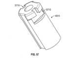
例示的な一実施形態では、カテーテルおよびドッキングステーションと、スリーブと、ドッキングステーション保定具と、ドッキングステーション。ドッキングステーション保定具はスリーブ内に配設することができる。ドッキングステーション保定具は、1つまたは複数の保定具陥凹部を含むことができる。ドッキングステーションはスリーブ内に配設することができる。ドッキングステーションは、ドッキングステーション保定具に解放可能に取り付けられた1つまたは複数の延長部を含むことができる。1つまたは複数の延長部の各延長部は、1つまたは複数の保定具陥凹部のうちの少なくとも1つに配設されたヘッドを含むことができる。1つまたは複数のドッキング延長部の各延長部は、2点のみでドッキングステーション保定具に接触するように構成することができる。ヘッドは三角形であることができ、2つのヘッドが含まれてもよい。1つまたは複数の保定具陥凹部は、ドッキングステーション保定具の長方形の陥凹部であることができる。ヘッドの側面は、60度~120度の角度で互いから離れるように延在することができる。スリーブは、スリーブが1つまたは複数の延長部の上に位置付けられたとき、1つまたは複数の延長部を係合して、1つまたは複数のヘッドを保定具陥凹部内で保定することができる。1つまたは複数の延長部は、スリーブによる拘束を解かれたとき、ドッキングステーション保定具に対して径方向外側に跳ねて、1つまたは複数の延長部をドッキングステーション保定具から解放することができる。1つまたは複数の延長部は、1つまたは複数の陥凹部内で傾けることができる。本開示の別の箇所に記載する他の特徴も含まれてもよい。 In one exemplary embodiment, a catheter and docking station, a sleeve, a docking station retainer, and a docking station. A docking station retainer can be disposed within the sleeve. The docking station retainer can include one or more retainer recesses. A docking station can be disposed within the sleeve. The docking station can include one or more extensions releasably attached to the docking station retainer. Each extension of the one or more extensions can include a head disposed in at least one of the one or more retainer recesses. Each extension of the one or more docking extensions may be configured to contact the docking station retainer at only two points. The head can be triangular and may include two heads. The one or more retainer recesses can be rectangular recesses of the docking station retainer. The sides of the head can extend away from each other at an angle of 60 degrees to 120 degrees. The sleeve is capable of engaging the one or more extensions to retain the head or heads within the retainer recess when the sleeve is positioned over the one or more extensions. can. The one or more extensions can spring radially outwardly relative to the docking station retainer when unconstrained by the sleeve, releasing the one or more extensions from the docking station retainer. . The one or more extensions can be tilted within the one or more recesses. Other features described elsewhere in this disclosure may also be included.
例示的な一実施形態では、ドッキングステーションを使用する方法は、ドッキングステーション延長部が2点のみでドッキングステーション保定具に接触するようにして、ドッキングステーション延長部のヘッドをドッキングステーション保定具の陥凹部内に配置するステップを含むことができる。ドッキングステーションおよびドッキングステーション保定具は、スリーブ内に配置することができる。スリーブは、ドッキングステーション延長部を係合して、ドッキングステーション延長部のヘッドを陥凹部内で保定することができる。ヘッドは三角形であることができる。陥凹部は、ドッキングステーション保定具の長方形の陥凹部であることができる。ヘッドの側面は、60度~120度の角度で互いから離れるように延在することができる。保定具およびドッキングステーションは、ドッキングステーション延長部のヘッドがドッキングステーション保定具に対して径方向外側に跳ねて、ドッキングステーション延長部をドッキングステーション保定具から解放するように、スリーブから除去することができる。延長部は陥凹部内で傾けることができる。本開示の別の箇所に記載する他の特徴/ステップも含まれてもよい。 In one exemplary embodiment, a method of using a docking station includes connecting the head of the docking station extension to a recess in the docking station retainer such that the docking station extension contacts the docking station retainer at only two points. The method may include the step of locating within. The docking station and docking station retainer can be placed within the sleeve. The sleeve can engage the docking station extension to retain the head of the docking station extension within the recess. The head can be triangular. The recess can be a rectangular recess in the docking station retainer. The sides of the head can extend away from each other at an angle of 60 degrees to 120 degrees. The retainer and docking station can be removed from the sleeve such that the head of the docking station extension springs radially outward relative to the docking station retainer, releasing the docking station extension from the docking station retainer. . The extension can be tilted within the recess. Other features/steps described elsewhere in this disclosure may also be included.
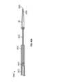
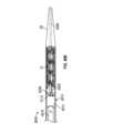
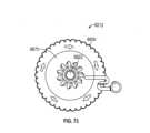
例示的な一実施形態では、ドッキングステーションを配備するアセンブリは、ハンドルとカテーテルとを含む。ハンドルは、ハウジングと、駆動部材と、被動部材とを含むことができる。駆動部材は、ハウジングに回転可能に連結することができる。被動部材は、駆動部材の回転によって被動部材がハウジング内で線形的に移動するようにして、駆動部材およびハウジングに連結することができる。カテーテルは、外側スリーブと内側スリーブとを含むことができる。外側スリーブは被動部材に固定的に接続することができる。内側スリーブは、外側スリーブ内に配設することができ、ハウジングに固定的に接続することができる。駆動部材の回転によって、外側スリーブを内側スリーブに対して移動させることができる。駆動部材は、歯車部分を有するホイールを備えることができる。駆動部材は雌ねじ部材を含むことができる。被動部材はラック歯車を含むことができる。被動部材は雄ねじ部材を含むことができる。ラチェット機構は、ラチェットが係合位置にあるとき、駆動部材を一方向のみで回転させることができるように、係合位置から係脱位置へと移動可能であることができる。ルアーポートは内側スリーブに固定されてもよい。ルアーポートおよび内側スリーブは、内側軸を通って延在するガイドワイヤを受け入れるように構成することができる。本開示の別の箇所に記載する他の特徴も含まれてもよい。 In one exemplary embodiment, an assembly for deploying a docking station includes a handle and a catheter. The handle can include a housing, a drive member, and a driven member. A drive member can be rotatably coupled to the housing. The driven member can be coupled to the drive member and the housing such that rotation of the drive member causes linear movement of the driven member within the housing. The catheter can include an outer sleeve and an inner sleeve. The outer sleeve can be fixedly connected to the driven member. The inner sleeve can be disposed within the outer sleeve and can be fixedly connected to the housing. Rotation of the drive member can move the outer sleeve relative to the inner sleeve. The drive member can include a wheel having a geared portion. The drive member can include an internally threaded member. The driven member can include a rack gear. The driven member can include an externally threaded member. The ratchet mechanism can be movable from the engaged position to the disengaged position such that when the ratchet is in the engaged position, the drive member can be rotated in only one direction. The luer port may be secured to the inner sleeve. The luer port and inner sleeve can be configured to receive a guidewire extending through the inner shaft. Other features described elsewhere in this disclosure may also be included.
例示的な一実施形態では、ドッキングステーションを配備する方法は、駆動部材をハウジングに対して回転させて、被動部材をハウジング内で線形的に移動させるステップを含むことができる。内側スリーブはハウジングに固定することができ、外側スリーブは被動部材に固定することができる。駆動部材の回転によって、外側スリーブが内側スリーブに対して移動する。駆動部材は、歯車歯の係合によって被動部材を線形的に移動させることができる。駆動部材は、ねじの係合によって被動部材を線形的に移動させることができる。駆動部材は、一方向のみで回転するように構成することができる。第1および第2のスリーブはガイドワイヤを越えて移動させることができる。 In one exemplary embodiment, a method of deploying a docking station can include rotating a drive member relative to a housing to linearly move a driven member within the housing. The inner sleeve can be secured to the housing and the outer sleeve can be secured to the driven member. Rotation of the drive member moves the outer sleeve relative to the inner sleeve. The drive member can linearly move the driven member through engagement of gear teeth. The driving member can linearly move the driven member through threaded engagement. The drive member may be configured to rotate in only one direction. The first and second sleeves can be moved over the guidewire.
本開示の任意の箇所に記載するような様々な特徴は、ここに概説した例に含まれてもよく、本明細書の任意の箇所に記載するようなものを含む、例および特徴を使用する様々な方法およびステップが使用されてもよい。 Various features as described elsewhere in this disclosure may be included in the examples outlined herein, and using examples and features, including as described elsewhere in this specification. Various methods and steps may be used.
開示する発明の性質および利点の更なる理解は、特に添付図面と併せて検討した場合に、以下の説明および特許請求の範囲から得ることができる。図面中、同様の部分は同様の参照番号を有する。 A further understanding of the nature and advantages of the disclosed invention can be obtained from the following description and claims, particularly when considered in conjunction with the accompanying drawings. In the drawings, like parts have like reference numbers.
本開示の実施形態の様々な態様を更に明確にするため、添付図面の様々な態様を参照することによって、特定の実施形態について更に具体的に説明する。これらの図面は本開示の典型的な実施形態を描いたものにすぎず、したがって、本開示の範囲を限定するものとは見なされないことが認識される。更に、図面は、一部の実施形態については縮尺通りに描かれていることがあるが、必ずしも全ての実施形態に関して縮尺通りに描かれているとは限らない。添付図面を用いて、本開示の実施形態について、更なる特異性および詳細とともに記載し説明する。 To further clarify various aspects of embodiments of the present disclosure, certain embodiments will now be described more particularly by reference to various aspects of the accompanying drawings. It is recognized that these drawings depict only typical embodiments of the disclosure and, therefore, are not to be considered limiting the scope of the disclosure. Further, the drawings may be drawn to scale for some embodiments, but not necessarily for all embodiments. Embodiments of the disclosure will be described and explained with further specificity and details with the aid of the accompanying drawings.
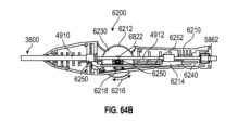
以下の説明は、本発明の特定の実施形態を示す添付図面を参照する。異なる構造および動作を有する他の実施形態は本発明の範囲から逸脱しない。本開示の例示的な実施形態は、経カテーテル心臓弁(「THV」)、例えばTHV 29のためのドッキングステーションまたはランディング域を提供する、デバイスおよび方法を対象とする。いくつかの例示的な実施形態では、THVのドッキングステーションは肺動脈内で使用されるものとして示されるが、ドッキングステーション(例えば、ドッキングステーション10)は、上大静脈または下大静脈など、解剖学的構造、心臓、または脈管系の他の領域で使用されてもよい。本明細書に記載するドッキングステーションは、中にTHVが配置される空間(例えば、解剖学的構造/脈管系/その他)よりも配備されたTHVが小さいことを補うように構成することができる。 The following description refers to the accompanying drawings that illustrate specific embodiments of the invention. Other embodiments having different structure and operation do not depart from the scope of the invention. Exemplary embodiments of the present disclosure are directed to devices and methods that provide a docking station or landing area for a transcatheter heart valve (“THV”), such as
送達および埋込みのためのドッキングステーションおよびシステムの様々な実施形態が本明細書に開示され、それらの選択肢が、具体的に除外されない限りどのように組み合わされてもよいことに留意すべきである。例えば、特定の組み合わせが明示的に記載されていない場合であっても、開示されるドッキングステーションデバイスのうちのいずれも、任意のタイプの弁、および/または任意の送達システムとともに使用されてもよい。同様に、明示的に開示されていない場合であっても、任意のドッキングステーションのタイプ/特徴、弁のタイプ/特徴、ティシューカバーなどを組み合わせることなどによって、ドッキングステーションおよび弁の異なる構造が混合され整合されてもよい。簡単に言えば、相互に排他的であるかまたは別の理由で物理的に不可能でない限り、開示されるシステムの個々の構成要素が組み合わされてもよい。 It should be noted that various embodiments of docking stations and systems for delivery and implantation are disclosed herein and that the options may be combined in any manner unless specifically excluded. For example, any of the disclosed docking station devices may be used with any type of valve and/or any delivery system, even if a particular combination is not explicitly described. . Similarly, even if not explicitly disclosed, different docking station and valve configurations may be mixed, such as by combining any docking station type/feature, valve type/feature, tissue cover, etc. May be aligned. Briefly, the individual components of the disclosed system may be combined unless they are mutually exclusive or physically impossible for other reasons.
統一のため、本出願のこれらの図面およびその他では、ドッキングステーションは、肺動脈分岐側端部を上に、心室側端部を下にして描かれる。これらの方向は、上側または肺動脈分岐側端部と同義語としての「遠位側」、および下側または心室側端部と同義語としての「近位側」と呼ばれることもあり、これらは医師の視点に対する用語である。 For the sake of uniformity, in these figures and elsewhere in this application, the docking station is drawn with the pulmonary artery bifurcation end up and the ventricular end down. These directions are sometimes referred to as "distal" as synonymous with the superior or pulmonary artery bifurcation end, and "proximal" as synonymous with the inferior or ventricular end, and are It is a term for the viewpoint of
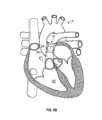
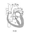
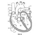
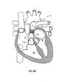
図1Aおよび図1Bはそれぞれ、拡張期および収縮期のヒトの心臓Hの切欠図である。右心室RVおよび左心室LVはそれぞれ、三尖弁TVおよび僧帽弁MV、即ち房室弁によって、右心房RAおよび左心房LAから分離されている。それに加えて、大動脈弁AVは左心室LVを上行大動脈(図示なし)から分離し、肺動脈弁PVは右心室を肺動脈PAから分離している。これらの弁はそれぞれ、流れの中で一体となるかまたは「接合」して一方向の流体閉塞面を形成する、それぞれのオリフィスを横切って内向きに延在する柔軟な弁尖を有する。本出願のドッキングステーションおよび弁については、主に肺動脈弁に関して記載する。したがって、右心房RAおよび右心室RVの解剖学的構造について、更に詳細に説明する。本明細書に記載するデバイスは、例えば、逆流または他の欠陥がある三尖弁の治療として下大静脈および/または上大静脈で、欠陥がある大動脈弁の治療として大動脈で(例えば、大動脈肥大)、心臓または脈管系の他の領域で、グラフトでなど、他の領域でも使用されてもよいことが理解されるべきである。 Figures 1A and 1B are cutaway views of a human heart H during diastole and systole, respectively. The right ventricle RV and left ventricle LV are separated from the right atrium RA and left atrium LA by the tricuspid TV and mitral MV, or atrioventricular valves, respectively. In addition, the aortic valve AV separates the left ventricle LV from the ascending aorta (not shown), and the pulmonary valve PV separates the right ventricle from the pulmonary artery PA. Each of these valves has flexible leaflets extending inwardly across their respective orifices that come together or "join" in flow to form a unidirectional fluid-occluding surface. The docking station and valve of this application will be described primarily with respect to the pulmonic valve. Therefore, the anatomy of the right atrium RA and right ventricle RV will be described in more detail. The devices described herein can be used, for example, in the inferior and/or superior vena cava as a treatment for regurgitation or other defective tricuspid valves, and in the aorta as a treatment for defective aortic valves (e.g., aortic hypertrophy). ), in the heart or other areas of the vascular system, it should be understood that it may also be used in other areas, such as in grafts.
右心房RAは、上方から右心房に入る上大静脈SVC、および下方から入る下大静脈IVCを通して、静脈系から脱酸化血液を受け取る。冠静脈洞CSは静脈の集合体であって、互いに接合されて、脱酸素化血液を心臓の筋肉(心筋)から回収し右心房RAに送達する大きい脈管を形成する。図1Aに見られる拡張期または心拡張期の間、右心房RAに集まる静脈血は、右心室RVの拡張によって三尖弁TVに入る。図1Bに見られる収縮期または心収縮期では、右心室RVが収縮して、肺動脈弁PVおよび肺動脈を通して静脈血を肺へと押し流す。例示的な一実施形態では、本出願によって記載されるデバイスは、欠陥がある肺動脈弁の機能を置換または補足するのに使用される。心収縮期の間、三尖弁TVの弁尖は閉じて、静脈血が逆流して右心房RAに戻るのを防ぐ。 The right atrium RA receives deoxidized blood from the venous system through the superior vena cava SVC, which enters the right atrium from above, and the inferior vena cava IVC, which enters from below. The coronary sinus CS is a collection of veins joined together to form a large vessel that withdraws deoxygenated blood from the heart muscle (myocardium) and delivers it to the right atrium RA. During diastole or diastole, seen in Figure 1A, venous blood that collects in the right atrium RA enters the tricuspid TV by dilation of the right ventricular RV. During systole, or systole, seen in Figure 1B, the right ventricle RV contracts, forcing venous blood through the pulmonary valve PV and pulmonary artery to the lungs. In one exemplary embodiment, the device described by this application is used to replace or supplement the function of a defective pulmonary valve. During systole, the tricuspid TV leaflets close to prevent venous blood from flowing backwards back into the right atrium RA.
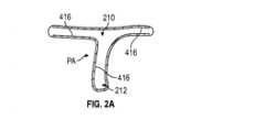
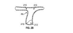
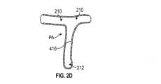
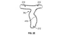
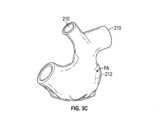
図2A~図2Eおよび図3A~図3Dを参照すると、図示される非網羅的な例は、肺動脈が多種多様な異なる形状およびサイズを有し得ることを示している。例えば、図2A~図2Eの断面図および図3A~図3Dの斜視図に示されるように、長さL、直径D、および曲率または輪郭は、異なる患者の肺動脈間で大幅に異なることがある。更に、直径Dは、個々の肺動脈の長さLに沿って大幅に異なることがある。これらの差は、特定の疾患を患っている、および/または過去の外科手術によって障害を生じている肺動脈において、より一層顕著である場合がある。例えば、ファロー四徴症(TOF)または大動脈転位(TGA)の治療は、より大きくより不規則な形状の肺動脈をもたらす場合が多い。 Referring to FIGS. 2A-2E and 3A-3D, the illustrated non-exhaustive examples illustrate that pulmonary arteries can have a wide variety of different shapes and sizes. For example, the length L, diameter D, and curvature or contour can vary significantly between pulmonary arteries of different patients, as shown in the cross-sectional views of Figures 2A-2E and perspective views of Figures 3A-3D. . Furthermore, the diameter D can vary significantly along the length L of individual pulmonary arteries. These differences may be even more pronounced in pulmonary arteries that suffer from certain diseases and/or have been compromised by previous surgery. For example, treatment of tetralogy of Fallot (TOF) or transposition of the great arteries (TGA) often results in larger and more irregularly shaped pulmonary arteries.
ファロー四徴症(TOF)は、一般的に併発する4つの関連する心臓欠陥の組み合わせを指す心臓異常である。4つの欠陥は、心室中隔欠損(VSD)、大動脈騎乗(大動脈弁が肥大し、正常な心臓のように左心室から出る代わりに、左右両方の心室から出ているように見える)、肺動脈狭窄(右心室から肺動脈への血流の閉塞を引き起こす、肺動脈弁および弁の下方の流出路または流出域の狭小化)、ならびに右心室肥大(右心室が高圧でポンピングすることによって起こる、右心室の筋肉壁の肥厚)である。 Tetralogy of Fallot (TOF) is a cardiac abnormality that refers to a combination of four related heart defects that commonly occur together. The four defects are ventricular septal defect (VSD), aortic riding (the aortic valve is enlarged and appears to exit from both the left and right ventricles instead of exiting from the left ventricle as in a normal heart), and pulmonary artery stenosis. (a narrowing of the outflow tract or outflow zone under the pulmonary valve and valve, causing obstruction of blood flow from the right ventricle to the pulmonary artery) and right ventricular hypertrophy (a narrowing of the right ventricle that occurs when the right ventricle pumps at high pressure). muscle wall thickening).
大動脈転位(TGA)は、大動脈および肺動脈がそれらの正常位置から「転位」して、大動脈が右心室から、肺動脈が左心室から出るようになる異常を指す。 Transposition of the great arteries (TGA) refers to an abnormality in which the aorta and pulmonary artery are "transposed" from their normal position, such that the aorta exits the right ventricle and the pulmonary artery exits the left ventricle.
いくつかの疾患の外科的治療には、肺動脈に沿って、肺動脈分枝の1つまでそれに沿って長手方向で切開する必要がある。この切開は、肺動脈弁の機能を排除するかまたは著しく損なう場合がある。外科手術後に切開を被覆するのにトランスアニュラーパッチが使用される。トランスアニュラーパッチは、他の外科手術と関連付けられる肺動脈PAの狭窄または拘束疾患を低減させる。しかしながら、肺動脈弁PVの障害または排除は著しい逆流を生じる場合があり、本発明以前は、後に開胸手術を行って肺動脈弁を置換することが必要な場合が多かった。トランスアニュラーパッチ技術は、広範囲の様々なサイズおよび形状を有する肺動脈をもたらすことができる(図3A~図3Dを参照)。 Surgical treatment of some diseases requires making a longitudinal incision along the pulmonary artery, up to one of the pulmonary artery branches. This incision may eliminate or significantly impair the function of the pulmonary valve. Transannual patches are used to cover incisions after surgery. The transannular patch reduces pulmonary artery PA stenosis or restrictive disease associated with other surgical procedures. However, obstruction or elimination of the pulmonic valve PV can result in significant regurgitation, and prior to the present invention, subsequent open-heart surgery was often required to replace the pulmonic valve. The transannular patch technique can yield pulmonary arteries with a wide variety of sizes and shapes (see Figures 3A-3D).
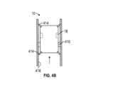
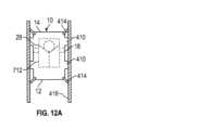
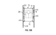
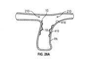
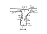
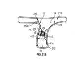
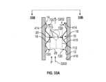
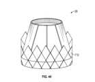
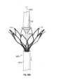
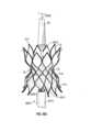
図4A~図4Fを参照すると、例示的な一実施形態では、拡張型ドッキングステーション10は、1つまたは複数の封止部分410と、弁座18と、1つまたは複数の保定部分414とを含む。封止部分410は、ドッキングステーション10と循環系の内表面416との間にシールをもたらす。弁座18は、ドッキングステーション10が循環系に埋め込まれた後、ドッキングステーション10内に弁29を埋め込むかまたは配備するための支持面となる。保定部分414は、ドッキングステーション10および弁29を、循環系内の埋込み位置または配備部位で保定するのを助ける。本明細書の様々な実施形態に記載するような拡張型ドッキングステーション10および弁29はまた、既知のものであり得るかまたは開発され得る様々なドッキングステーションおよび/または弁を表し、例えば、様々な異なるタイプの弁を、様々なドッキングステーション内の弁29の代用とする、および/または弁29として使用することができる。 4A-4F, in one exemplary embodiment, the
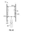
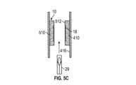
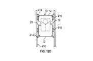
図4A~図4Dは、循環系内におけるドッキングステーション10および弁29の例示的な配備を概略的に示している。図4Aを参照すると、ドッキングステーション10は、圧縮形態/構成であり、循環系内の配備部位に導入される。例えば、ドッキングステーション10は、カテーテル(例えば、図50A~図50Dに示されるようなカテーテル3600)によって、肺動脈内の配備部位に位置付けられてもよい。図4Bを参照すると、ドッキングステーション10は、封止部分410および保定部分414が循環系の一部分の内表面416を係合するようにして、循環系内で拡張される。図4Cを参照すると、ドッキングステーション10が配備された後、弁29は、圧縮形態であり、ドッキングステーション10の弁座18に導入される。図4Dを参照すると、弁29はドッキングステーション内で拡張されて、弁29が弁座18を係合する。本明細書に描写される例では、ドッキングステーション10は弁よりも長い。しかしながら、他の実施形態では、ドッキングステーション10は、弁29と同じ長さであるかまたはそれよりも短いことが可能である。同様に、弁座18は、弁29よりも長い長さ、短い長さ、またはそれと同じ長さであることができる。 4A-4D schematically illustrate an exemplary deployment of
図4Dを参照すると、弁29が拡張し、ドッキングステーションの弁座18が弁を支持している。弁29は、ドッキングステーション10が占めている循環系の部分内のより幅が広い空間に対してではなく、幅が狭い弁座18に対して拡張すればよい。ドッキングステーション10によって、弁29が、それに合わせて設計されている拡張直径範囲内で動作することが可能になる。 Referring to FIG. 4D,
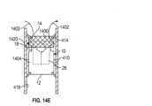
図4Eは、心臓の血管または解剖学的構造の内表面など、循環系の内表面416の断面のサイズおよび/または形状が、その長さに沿って変化し得ることを示している。例示的な一実施形態では、ドッキングステーション10は、その長さLに沿って様々な程度に径方向外側に拡張して、内表面416の形状に一致するように構成される。例示的な一実施形態では、ドッキングステーション10は、心臓の血管または解剖学的構造の形状がドッキングステーションの長さLに沿って大幅に変化するにもかかわらず、封止部分410および/または保定部分が内表面416を係合するように構成される。ドッキングステーションは、解剖学的構造の大きいばらつきに適応する、非常に弾力性または順応性が高い材料から作ることができる。例えば、ドッキングステーションは、高可撓性の金属、合金、ポリマー、または連続気泡発泡体から作ることができる。使用することができる金属および合金の例としては、非限定的に、ニチノール、エルジロイ、およびステンレス鋼が挙げられるが、他の金属および非常に弾力性または順応性が高い非金属材料を使用することができる。例えば、ドッキングステーション10は、これらの材料から、例えばニチノールなどの形状記憶材料から作られた、フレームまたはフレームの一部分(例えば、自己拡張型フレーム、保定部分、封止部分、弁座など)を有することができる。これらの材料によって、フレームを小さいサイズまで圧縮することが可能になり、次に圧縮力が解放されたとき、フレームは自己拡張してその圧縮前直径に戻る。 FIG. 4E shows that the cross-sectional size and/or shape of the
ドッキングステーションまたはドッキングステーションの一部分を形成するのに使用することができる連続気泡発泡体の一例は、(例えば、Biometrix, Rockville, MDから入手できるような)ポリウレタン発泡体などの生体適合性発泡体である。本明細書に記載するドッキングステーションは、自己拡張型、および/または膨張式デバイスを用いて拡張可能であって、ドッキングステーションによって可変の形状を有する内表面416を係合させることができる。 An example of an open cell foam that can be used to form the docking station or a portion of the docking station is a biocompatible foam such as polyurethane foam (e.g., as available from Biometrix, Rockville, MD). be. The docking stations described herein are expandable using self-expanding and/or inflatable devices to allow the docking station to engage an
図4Fは、肺動脈PAに埋め込まれたドッキングステーション10および弁29を示している。図2A~図2Eおよび図3A~図3Dに関して言及したように、肺動脈の形状はその長さに沿って大幅に変化することがある。例示的な一実施形態では、ドッキングステーション10は、図4Eに関して記載したのと同じ形で、肺動脈PAの変化する形状に一致するように構成される。 Figure 4F shows the
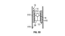
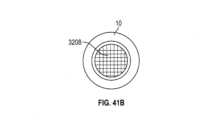
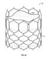
図5A~図5Fを参照すると、例示的な一実施形態では、拡張型ドッキングステーション10は、連続気泡生体適合性発泡体などの拡張型発泡体材料から作られる。発泡体材料の外表面510は封止部分410としての役割を果たすことができる。この例では、弁座18は、図示されるような発泡体材料の内表面512に設けることができ、または内表面512は弁座としての役割を果たすことができる。図5A~図5Fによって示される例では、保定部分414は省略されているが、保定部分を使用することができる。一実施形態では、発泡体材料を、(例えば、金属、形状記憶材料などの)拡張型フレームとともに使用することができる。発泡体材料は、フレームの全長またはフレームの長さの一部分のみを被覆するかもしくは延在することができる。 Referring to FIGS. 5A-5F, in one exemplary embodiment,
図5A~図5Dは、循環系内における発泡体ドッキングステーション10および弁29の配備を概略的に示している。図5Aを参照すると、ドッキングステーション10は、圧縮形態であり、循環系の配備部位に導入される。例えば、ドッキングステーション10は、カテーテル(例えば、図50A~図50Dに示されるカテーテル3600)によって、肺動脈内の配備部位に位置付けられてもよい。図5Bを参照すると、ドッキングステーション10は、封止部分410が循環系の内表面416を係合するようにして、循環系内で拡張される。図5Cを参照すると、ドッキングステーション10が配備された後、弁29は、圧縮形態であり、ドッキングステーション10の弁座18または内表面512に導入される。図5Dを参照すると、弁29は、弁29が弁座18または内表面512(例えば、内表面512が弁座として作用する場合)を係合するようにして、ドッキングステーション内で拡張される。 Figures 5A-5D schematically illustrate the deployment of
図5Eは、心臓の血管または解剖学的構造の内表面など、循環系の内表面416の断面が、その長さに沿って変化し得ることを示している。例示的な一実施形態では、発泡体ドッキングステーション10は、その長さLに沿って様々な程度に径方向外側に拡張して、内表面416の形状に一致するように構成される。 FIG. 5E shows that the cross-section of the
図5Fは、肺動脈PAに埋め込まれた発泡体ドッキングステーション10および弁29を示している。図2A~図2Eおよび図3A~図3Dに関して言及したように、肺動脈の形状はその長さに沿って大幅に変化することがある。例示的な一実施形態では、ドッキングステーション10は、図4Eに関して記載したのと同じまたは類似の形で、肺動脈PAの変化する形状に一致するように構成される。 Figure 5F shows the
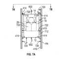
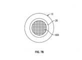
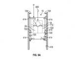
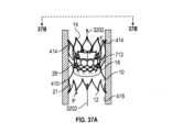
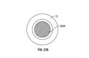
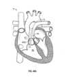
図6Aを参照すると、ドッキングステーション、例えば図4A~図4Dに関して記載したようなドッキングステーションは、心臓Hの肺動脈PA内に配備される。図6Bは、図6Aによって示されるドッキングステーション10内に配備された弁29を示している。図6Aおよび図6Bでは、心臓は収縮期である。図7Aは、図6Bの肺動脈内のドッキングステーション10および弁29の拡大表現である。心臓が収縮期のとき、弁29は開く。血液は、矢印602によって示されるように、右心室RVから、肺動脈PA、ドッキングステーション10、および弁29を通って流れる。図7Bは、心臓が収縮期のときに弁29が開いていることを表す空間608を示している。図7Bは、図面を単純にするため、ドッキングステーション10と肺動脈の境界面は示していない。図7Bの斜影線は開いた弁を通る血流を示している。例示的な一実施形態では、封止部分410によって、血液が肺動脈PAとドッキングステーション10の間を流れないようにされ、また弁29をドッキングステーション10の弁座18に収めることによって、血液がドッキングステーション10と弁29の間を流れないようにされる。この例では、血液は実質的に、心臓が収縮期のとき弁29を通って流れているのみであるか、または流れることができるのみである。 Referring to FIG. 6A, a docking station, such as that described with respect to FIGS. 4A-4D, is deployed within the pulmonary artery PA of the heart H. Figure 6B shows the
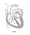
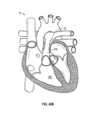
図8は、心臓が拡張期のときの、図6Bによって示される弁29と、ドッキングステーション10と、心臓Hとを示している。図9Aおよび図9Bを参照すると、心臓が拡張期のとき、弁29は閉じる。図9Aは、図8の肺動脈29内のドッキングステーション10および弁29の拡大表現である。弁29の上方における肺動脈PA内(即ち、肺動脈分枝760内)の血流は、弁29が閉じられることによって阻害され、矢印900によって示されるような血流を阻害する。図9Bの中実領域912は、心臓が拡張期のときは弁29が閉じられていることを表す。 FIG. 8 shows the
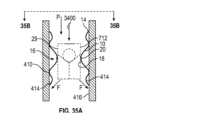
例示的な一実施形態では、ドッキングステーション10は、弁29の径方向外向きの力が循環系の内表面416に移行されることを防止または実質的に防止する、アイソレータとして作用する。一実施形態では、ドッキングステーション10は、弁座18(THVもしくは弁29の径方向外向きの力によって径方向外側に拡張されない、または径方向外側に実質的に拡張されない、即ち、弁座の直径がTHVの力によって増加しない、または4mm以上増加しない)と、(弁29によって弁座18に加えられる径方向外向きの力と比べて)比較的小さい径方向外向きの力720、722しか循環系の内表面416に対して付与しない、固着/保定部分414および封止部分410とを含む。 In one exemplary embodiment, the
ドッキングステーションが使用されない場合、THVのステントおよびフレームは、循環系の内表面416に直接作用する、THVのステントまたはフレーム712の比較的高い径方向外向きの力710によって、循環系内の所定位置で保持される。図7Aによって示される例のように、ドッキングステーションが使用される場合、弁29のステントまたはフレーム712は、径方向外側に拡張するか、または径方向外側に拡張されて、ドッキングステーション10の弁座18に対して大きい力710を付与する。この大きい径方向外向きの力710が、弁29をドッキングステーション10の弁座18に固定する。しかしながら、弁座18は力710によって拡張されないか、または実質的に拡張されないので、力710は、ドッキングステーションを循環系内で固定するのに使用されるのではなく、循環系から隔離される。 When a docking station is not used, the THV stent and frame are held in position within the circulatory system by a relatively high radially
例示的な一実施形態では、内表面416に対する封止部分410の径方向外向きの力722は、弁座18に対して弁29によって加えられる径方向外向きの力710よりも実質的に小さい。例えば、径方向外向きの封止力722は、弁によって加えられる径方向外向きの力710の1/2未満、弁によって加えられる径方向外向きの力710の1/3未満、弁によって加えられる径方向外向きの力710の1/4未満、弁によって加えられる径方向外向きの力710の1/8未満、または更には1/10未満であることができる。例示的な一実施形態では、封止部分410の径方向外向きの力722は、内表面416と封止部分410の間にシールを提供するように選択されるが、それ自体では循環系内における弁29およびドッキングステーション10の位置を保定するのに不十分である。 In one exemplary embodiment, the radially
例示的な一実施形態では、内表面416に対する固着/保定部分414の径方向外向きの力720は、弁座18に対して弁29によって加えられる径方向外向きの力710よりも実質的に小さい。例えば、径方向外向きの封止力720は、弁によって加えられる径方向外向きの力710の1/2未満、弁によって加えられる径方向外向きの力710の1/3未満、弁によって加えられる径方向外向きの力710の1/4未満、弁によって加えられる径方向外向きの力710の1/8未満、または更には1/10未満であることができる。 In one exemplary embodiment, the radially
例示的な一実施形態では、保定部分414の径方向外向きの力720は、それ自体では循環系内で弁29およびドッキングステーション10の位置を保定するのに不十分である。それよりもむしろ、血液608の圧力は、内表面416に対する保定部分414の保定を強化するのに使用される。図6Aを再び参照すると、心臓が収縮期のとき、弁29は開き、血液は矢印602によって示されるように弁を通って流れる。弁29は開いており、血液は弁29を通って流れるので、図7Aに示される小さい矢印Pによって示されるように、血液によってドッキングステーション10および弁29に加えられる圧力Pは低い。圧力Pは低いものの、ドッキングステーションおよびその上側保定部分414を、ほぼ矢印Fによって示される方向で表面416に押し付ける。保定部分414によって表面416に加えられるこの血流で支援される力Fは、ドッキングステーション10および弁29が、心臓Hの収縮期に血流の方向602で移動するのを防ぐ。 In one exemplary embodiment, the radially
図9Aを参照すると、心臓が拡張期のとき、弁29は閉じられ、血流は矢印900によって示されるように阻害される。弁29は閉じており、弁29およびドッキングステーション10は血流を阻害するので、図9Aの大きい矢印Pによって示されるように、血液によってドッキングステーション10および弁29に加えられる圧力Pは高い。この高い圧力Pは、下側保定部分414を、ほぼ大きい矢印Fによって示される方向で表面416に押し付ける。保定部分414によって表面416に加えられるこの血流で支援される力Fは、ドッキングステーション10および弁29が矢印900によって示される方向で移動するのを防ぐ。 Referring to FIG. 9A, when the heart is in diastole,
上側および下側保定部分414によって加えられる力は、血液によって弁29およびドッキングステーション10に加えられる圧力量によって決まるので、表面416に加えられる力は自動的に比例する。即ち、心臓が収縮期のときに上側保定部分が表面416に押し付けられる力は、心臓が拡張期のときに下側保定部分が表面416に押し付けられる力よりも弱い。これは、収縮期の開いた弁29およびドッキングステーション10に対する圧力が、拡張期の閉じた弁およびドッキングステーションに対する圧力よりも低いためである。 Since the force exerted by the upper and
弁座18および封止部分410は多種多様な異なる形態であることができる。例えば、弁座18は、THVの径方向外向きの力によって、径方向外側に拡張されないか、または径方向外側に実質的に拡張されない任意の構造であることができる(即ち、配備後の位置/構成の弁座の直径は、拡張しないかまたは4mm未満しか拡張しなくてもよく、例えば、弁が弁座に配備されたとき、直径は1~4mmだけ拡張してもよい)。例えば、弁座18は、拡張に抵抗するかまたは拡張を制限する縫合糸もしくは金属リングを備えることができる。しかしながら、一実施形態では、弁座18(または本明細書に記載するいずれかの弁座)は、より広い範囲にわたって拡張可能であることができ、例えば、弁が弁座に配備されたとき、直径は5mm~30mm拡張してもよい。一実施形態では、直径は、直径5mmもしくは6mmから、直径20mm~29mm、24mm、26mm、29mmなどまで拡張するか、またはその範囲内の異なる直径から異なる直径まで拡張してもよい。更に拡張可能な場合であっても、弁座は、拡張が制限されたままであることができ、例えば、弁座に配置される弁の拡張された直径以上に弁座が拡張することを回避するか、または弁と弁座の間に生じる力によって弁を弁座内でしっかり保持する直径以上に拡張するのを回避するように制限される。弁座18は、ドッキングステーション10の本体の一部であるかもしくはその一部分を規定することができ、または弁座18は、ドッキングステーションの本体に取り付けられる別個の構成要素であることができる。弁座18は、弁よりも長い長さ、短い長さ、またはそれと同じ長さであることができる。弁座18は、弁座18が縫合糸または金属リングによって規定されているとき、弁29よりも大幅に短い長さであることができる。縫合糸または金属リングによって形成される弁座18は、弁29とドッキングステーションの間に狭い円周方向のシールラインを形成することができる。
様々な実施形態の封止部分410は多種多様な異なる形態であることができる。例えば、封止部分410は、ドッキングステーション10と循環系の表面416との間にシールをもたらす任意の構造であることができる。例えば、封止部分410は、布地、発泡体、生体適合性ティシュー、それらの組み合わせなどを含むことができる。封止部分410は、ドッキングステーション10の本体の一部であるかもしくはその一部分を規定することができ、および/または封止部分410は、ドッキングステーションの本体に取り付けられる別個の構成要素であることができる。ドッキングステーション10は、単一の封止部分410、または2つ、または2つを超える封止部分を含んでもよい。 The sealing
上述したように、例示的な一実施形態では、封止部分410は、小さい径方向外向きの力を表面416に加えるように構成される。小さい径方向外向きの力は、多種多様な異なる方法で与えることができる。例えば、封止部分は、非常に圧縮性または順応性の高い材料から作られてもよい。図7Cを参照すると、例示的な一実施形態では、ドッキングステーション10の本体は弾性または超弾性金属から作られる。1つのかかる金属はニチノールである。ドッキングステーション10の本体が金属圧縮材の格子から作られる場合、本体はばねの特性を有することができる。図7Cを参照すると、ばねのように、ドッキングステーションの本体が拘束されず、その最大直径まで弛緩できるとき、ドッキングステーションの本体は径方向外向きの力をほとんどまたは全く加えない。ドッキングステーション10の本体が圧縮されるにつれて、ばねのように、ドッキングステーションによって加えられる径方向外向きの力が増加する。図7Cによって示されるように、例示的な一実施形態では、ドッキングステーション本体の径方向外向きの力とドッキングステーションの拡張された直径との関係は非線形であるが、例示的な一実施形態では、その関係は線形的であることもできる。図7Cによって示される例では、曲線750は、ドッキングステーション10によって働かされる径方向外向きの力とドッキングステーションの圧縮された直径との関係を示している。領域752では、曲線750は小さい傾斜を有する。この領域752では、径方向外向きの力は小さく、少量しか変化しない。例示的な一実施形態では、領域752は、27mm~38mmなど、25mm~40mmの直径に相当する。径方向外向きの力は、領域752では小さいがゼロではない。領域754では、曲線750はより大きい傾斜を有する。この領域754では、ドッキングステーションが圧縮されるにつれて、径方向外向きの力は大幅に増加する。例示的な一実施形態では、ステントの本体は小さい傾斜の領域752にあるように構築される。これによって、封止部分710が、広範囲の直径にわたって、小さい径方向外向きの力しか循環系の内表面416に加えないようにすることができる。 As mentioned above, in one exemplary embodiment, sealing
保定部分414は多種多様な異なる形態であることができる。例えば、保定部分414は、循環系内でドッキングステーション10の位置を設定する任意の構造であってもよい。例えば、保定部分414は、内表面416に接してもしくはその中まで押し付けられるか、または循環系の解剖学的構造の周りに延在して、ドッキングステーション10の位置を設定してもよい。保定部分414は、ドッキングステーション10の本体の一部であるかもしくはその一部分を規定してもよく、または保定部分414は、ドッキングステーションの本体に取り付けられる別個の構成要素であってもよい。ドッキングステーション10は、単一の保定部分414、または2つ、または2つを超える保定部分を含んでもよい。
図10A~図10Cは、ドッキングステーション10が、1つもしくは1つを超える異なるタイプの弁座18および封止部分410の任意の組み合わせを有し得ることを示している。図10Aによって示される例では、弁座18は、ドッキングステーション10の本体に取り付けられる別個の構成要素であり、封止部分は、ドッキングステーションの本体と一体的に形成される。図10Bによって示される例では、弁座18は、ドッキングステーション10の本体に取り付けられる別個の構成要素であり、封止部分410は、ドッキングステーションの本体に取り付けられる別個の構成要素である。図10Cによって示される例では、弁座18は、ドッキングステーション10の本体と一体的に形成され、封止部分は、ドッキングステーションの本体と一体的に形成される。図10Dによって示される例では、弁座18は、ドッキングステーション10の本体と一体的に形成され、封止部分は、ドッキングステーション10の本体に取り付けられる別個の構成要素である。 10A-10C illustrate that
上述したように、肺動脈PAおよび循環系の他の解剖学的構造の長さは、患者ごとに大幅に異なることがある。図11A~図11Dを参照すると、例示的な一実施形態では、矢印1100によって示されるように、ドッキングステーション10の長さは調節可能である。この調節可能性1100は、ステントが圧縮状態から拡張状態へと拡張したときに本来的に起こる長さの変化ではなく、ドッキングステーションの埋込み後/拡張後の長さを調節するのが可能であることを指す。長さは多種多様な異なる方法で調節されてもよい。図11A~図11Dによって示される例では、ドッキングステーション10は第1の半片1102と第2の半片1104とを含む。本明細書で使用するとき、2部分のドッキングステーションに関する「半片」という語の使用は、「部分」と同義であり、第1および第2の半片または第1および第2の部分のサイズが等しいことを要せず、即ち、第1の半片は第2の半片よりも大きい/長い場合があり、その逆もまた真である。一実施形態では、第2の半片1104を第1の半片1102に挿入するかまたは「嵌め込む」ことができる。挿入または「嵌め込み」の量によって、ドッキングステーション10の長さが設定される。本特許出願において図示し記載するドッキングステーション10のいずれも、互いに入れ子式に嵌め込まれるかまたは別の方法で互いに対して調節可能である2部分からドッキングステーションを作成することによって、長さ調節可能であることができる。一実施形態では、単一片のドッキングステーションの長さは折畳み可能および拡張可能であることができる。一実施形態では、ドッキングステーションは、形状が変化して長さを調節することができる材料で形成されてもよい。一実施形態では、2つを超える部分(例えば、3つ、4つ、もしくはそれ以上の部分)を同様の方法で組み合わせ、第1の半片1102および第2の半片1104と同様の1つまたは複数の特徴を含むことができる。 As mentioned above, the length of the pulmonary artery PA and other anatomical structures of the circulatory system can vary significantly from patient to patient. Referring to FIGS. 11A-11D, in one exemplary embodiment, the length of
例示的な一実施形態では、ドッキングステーション10の長さは、最初にドッキングステーション10の第1の半片1102を肺動脈内に配備することによって、肺動脈PA内で調節することができる。例えば、第1の半片1102は、例えば第1の半片の遠位端1106が肺動脈の分枝と位置合わせされるか、またはそれをある程度越えて延在するように、所望に応じて位置付けられ拡張されてもよい。第1の半片1102が肺動脈内で拡張された後、遠位端1110が第1の半片1102の近位端1108に配設されるように、圧縮された第2の半片1104を位置付けることができる。一実施形態では、第2の半片1104の位置は、封止部分410および保定部分414が肺動脈と接触し、肺動脈内におけるドッキングステーション10の位置を設定するように選択される。適切に位置付けられてから、第2の半片1104が拡張される。一実施形態では、第2の半片1104の遠位端1110は、第1の半片の近位端1108を摩擦係合して、2つの半片1102、1104をともに固定する。一実施形態では、ロック、係止機構、縫合糸、交差、リンク、および/または他の取付けデバイス/機構が、半片/部分をともに固定する助けとするのに使用されてもよい。 In one exemplary embodiment, the length of
図11A~図11Dによって示される例では、弁座18および封止部分410はドッキングステーション10の第2の半片1104上に含まれる。しかしながら、他の実施形態では、弁座18および/または封止部分410を第1の半片1102上に含めることができる。図11A~図11Cは、ドッキングステーション10の半片1102、1104が異なるタイプの弁座18および封止部分410の任意の組み合わせを有し得ることを示している。図11Aによって示される例では、弁座18は、ドッキングステーション半片1104の本体に取り付けられる別個の構成要素であり、封止部分は、ドッキングステーション半片1104の本体と一体的に形成される。図11Bによって示される例では、弁座18は、ドッキングステーション半片1104の本体に取り付けられる別個の構成要素であり、封止部分410は、ドッキングステーション半片1104の本体に取り付けられる別個の構成要素である。図11Cによって示される例では、弁座18は、ドッキングステーション半片1104の本体と一体的に形成され、封止部分は、ドッキングステーション半片1104の本体と一体的に形成される。図11Dによって示される例では、弁座18は、ドッキングステーション半片1104の本体と一体的に形成され、封止部分410は、ドッキングステーション半片1104の本体に取り付けられる別個の構成要素である。 In the example illustrated by FIGS. 11A-11D, the
図12A~図12Dは、2つの封止部分410を有するドッキングステーション10の例示的な実施形態を示している。ドッキングステーション10は、1つもしくは1つを超える異なるタイプの弁座18および封止部分410の任意の組み合わせを有することができる。図12Aによって示される例では、弁座18は、ドッキングステーション10の本体に取り付けられる別個の構成要素であり、封止部分410は、ドッキングステーションの本体と一体的に形成される。図12Bによって示される例では、弁座18は、ドッキングステーション10の本体に取り付けられる別個の構成要素であり、封止部分410は、ドッキングステーションの本体に取り付けられる別個の構成要素である。図12Cによって示される例では、弁座18は、ドッキングステーション10の本体と一体的に形成され、封止部分は、ドッキングステーションの本体と一体的に形成される。図12Dによって示される例では、弁座18は、ドッキングステーション10の本体と一体的に形成され、封止部分は、ドッキングステーション10の本体に取り付けられる別個の構成要素である。 12A-12D illustrate an exemplary embodiment of
図13A~図13Dは、図12A~図12Dによって示されるドッキングステーションが二個片の入れ子式のドッキングステーションであり得ることを示している。ドッキングステーション10の個片1102、1104は、2つの個片のどちらかまたは両方に、1つまたは1つを超える異なるタイプの弁座18および封止部分410の任意の組み合わせを有することができる。図13Aによって示される例では、第1の半片1102は一体的な封止部分410を含む。第2の半片1104は、ドッキングステーション10の本体に取り付けられる別個の構成要素である弁座18を含み、封止部分410は、ドッキングステーションの本体と一体的に形成される。図13Bによって示される例では、第1の半片1102は、第1の半片102の本体とは別個である封止部分410を含む。弁座18は、ドッキングステーション10の本体に取り付けられる別個の構成要素であり、封止部分410は、ドッキングステーションの本体に取り付けられる別個の構成要素である。図13Cによって示される例では、第1の半片1102は一体的な封止部分410を含む。弁座18は、ドッキングステーション10の第2の半片1104の本体と一体的に形成され、封止部分410は、第2の半片1104の本体と一体的に形成される。図13Dによって示される例では、第1の半片1102は、第1の半片102の本体とは別個である封止部分410を含む。弁座18は、ドッキングステーション10の第2の半片1104の本体と一体的に形成され、封止部分410は、第2の半片1104の本体に取り付けられる別個の構成要素である。 13A-13D illustrate that the docking station illustrated by FIGS. 12A-12D can be a two-piece nested docking station. The
図14A~図14Gを参照すると、例示的な一実施形態では、ドッキングステーション10は、矢印1402によって示されるように血液が流れることができる透過性部分1400と、血液が流れることができない不透過性部分1404とを含むことができる。例示的な一実施形態では、不透過性部分1404は、少なくとも封止部分410から弁座18まで延在して、血液が弁29の周りを流れるのを防ぐ。例示的な一実施形態では、透過性部分1400を血液が自由に流れることができるので、循環系の内表面416を封止しない、または弁29を封止するドッキングステーションの部分が、血液の流れを阻害することがない。例えば、ドッキングステーション10は肺動脈の分枝内まで延在してもよく、肺動脈内まで延在するドッキングステーション10の部分1400によって、血液がドッキングステーション10を通って自由に流れることができる。例示的な一実施形態では、透過性部分1400を血液が自由に流れることができるので、心臓が拍動する際にドッキングステーションと循環系の間の領域1420が血液で洗い流され、それによって領域1420に血液がうっ滞するのが防止される。 14A-14G, in one exemplary embodiment,
不透過性部分1404は多種多様な異なる形態であることができる。不透過性部分1404は、血液が不透過性部分1404を通って流れるのを防ぐ任意の構造または材料であってもよい。例えば、ドッキングステーション10の本体は、ニチノールワイヤまたは格子などのワイヤまたは格子から形成することができ、本体のセルは不透過性材料によって被覆される(図18を参照)。多種多様な異なる材料が不透過性材料として使用されてもよい。例えば、不透過性材料は、PET布、もしくは血液不透過性のコーティングで処理された布地などの生体適合性被覆材料などの血液不透過性布、ポリエステル、または心膜などの加工済み生体材料であってもよい。
図14A~図14Gは、多種多様なドッキングステーション構成が透過性部分1402を備え得ることを示している。封止部分410は、図14B、図14D、および図14Fによって示されるようにドッキングステーションの本体と一体的に形成されるか、または図14C、図14E、および図14Gによって示されるように別個であってもよい。図14Fおよび図14Gでは、ドッキングステーション10は部分1410を含む。これらの部分1410は封止部分410に類似しているが、部分1410は透過性部分1402の一部なので、循環系の内表面416とのシールは形成されない。弁座18は、図14A~図14Cによって示されるようにドッキングステーションの本体とは別個に形成されるか、または図14D~図14Gに示されるようにドッキングステーション10の本体と一体的に形成されてもよい。 14A-14G illustrate that a wide variety of docking station configurations can include
図15A、図15B、図16、図17A、および図17Bは、ドッキングステーション10のフレーム1500または本体の例示的な一実施形態を示している。フレーム1500または本体は多種多様な異なる形態であることができ、図15A、図15B、図16、図17A、および図17Bは、多くの可能な構成のうちの1つのみを示している。図15A、図15B、図16、図17A、図17B、および図18によって示される例では、ドッキングステーション10は、比較的幅が広い近位側流入端部12および遠位側流出端部14と、端部12、14の間に弁座18を形成する比較的幅が狭い部分16とを有する。図15A、図15B、図17A、および図17Bによって示される例では、ドッキングステーション10のフレーム1500は、好ましくは、セル1504を形成する複数の金属圧縮材1502で構成された幅広のステントである。図15A、図15B、図17A、および図17Bの例では、フレーム1500は、近位端12および遠位端14の間に、不透過性材料によって被覆されると弁座18を形成する幅の狭い部分16を有する、ほぼ砂時計形状を有する。後述するように、弁18は幅の狭い部分16内で拡張し、それによって弁座18を形成する。 15A, 15B, 16, 17A, and 17B illustrate an exemplary embodiment of a
図15A、図15B、図17A、および図17Bは、拘束されていない拡張された状態のフレーム1500を示している。この例示的な実施形態では、保定部分414は、近位端12および遠位端14に金属圧縮材1502の端部1510を備える。封止部分410は保定部分414と腰部16の間である。非拘束状態では、保定部分414はほぼ径方向外側に延在し、封止部分410の径方向外側である。図16は、カテーテルによる送達および拡張のために圧縮状態にあるフレーム16を示している。ドッキングステーションは、解剖学的構造の大きいばらつきに適応する、非常に弾力性または順応性が高い材料から作ることができる。例えば、ドッキングステーションは、高可撓性の金属、合金、ポリマー、または連続気泡発泡体から作ることができる。高弾力性金属の一例はニチノールであるが、他の金属および非常に弾力性または順応性が高い非金属材料を使用することができる。ドッキングステーション10は、自己拡張型、手動拡張型(例えば、バルーンによって拡張可能)、または機械拡張型であってもよい。自己拡張型ドッキングステーション10は、例えばニチノールなどの形状記憶材料で作られてもよい。 15A, 15B, 17A, and
図18は、フレーム1500に取り付けられてドッキングステーション10を形成する不透過性材料21を含むフレーム1500を示している。図18を参照すると、例示的な一実施形態では、バンド20は、腰部もしくは幅が狭い部分16の周りに延在するか、または腰部と一体で、拡張不能もしくは実質的に拡張不能な弁座18を形成する。バンド20は腰部を補強し、一旦ドッキングステーションが配備され拡張されると、腰部/弁座がその配備後の構成では相対的に拡張不能になる。図19によって示される例では、弁29は、その折畳み可能なフレームが幅が狭い部分16内へと拡張することによって固定されることによって、ドッキングステーション10の弁座18を形成する。上述したように、拡張不能または実質的に拡張不能な弁座18は、弁29の径方向外向きの力が循環系の内表面416へと移行されるのを防ぐ。しかしながら、別の例示的な実施形態では、配備されたドッキングステーションの腰部/弁座は、任意に、弁がそこに対して配備されたときにわずかに弾性的に拡張してもよい。腰部18のこの任意の弾性的な拡張は、弁29に圧力を与えて、弁29をドッキングステーション内の所定位置で保持する助けとなり得る。 FIG. 18 shows a
バンドは、多種多様な異なる形態であることができ、多種多様な異なる材料から作ることができる。バンド20は、PET、1つもしくは複数の縫合糸、布地、金属、ポリマー、生体適合性テープ、または弁座18の形状を維持するとともに弁29を定位置で保持するのに十分な、当該分野で知られている他の相対的に拡張不能な材料で作ることができる。バンドは、ステントの外部の周りに延在することができ、または布地もしくは別の材料がステントのセル内にもしくはセルを通して織り交ぜられた場合など、その一体部分であることができる。バンド20は、図18の縫合糸バンドなど、幅が狭くてもよく、または幅が広くてもよい。バンドは様々な幅、長さ、および厚さであることができる。1つの非限定例では、弁座18は幅27~28mmであるが、弁座の直径は、弁座18内に固定される特定の弁29の動作範囲内であるべきであり、上述の例とは異なる場合がある。弁29は、ドッキングステーション内に入れられたとき、任意に、弁座のどちらかの側の周りでわずかに拡張することができる。この態様は、「ドッグボーン」と呼ばれる場合があり(例えば、弁座またはバンドの周りに形成する形状による)、弁を所定位置で保持する助けにもなり得る。 Bands can be in a wide variety of different forms and made from a wide variety of different materials.
図20および図21は、肺動脈などの循環系に埋め込まれた図18のドッキングステーション10を示している。封止部分410は、ドッキングステーション10と循環系の内表面416の間にシールをもたらす。図20および図21の例では、封止部分410は、フレーム1500またはその一部分の上に不透過性材料21(図21を参照)を提供することによって形成される。特に、封止部分410は、フレーム1500の下側の丸み付けられた径方向外側に延在する部分2000を備えることができる。例示的な一実施形態では、不透過性材料21は、少なくともフレーム1500の部分2000から弁座18まで延在する。これによって、ドッキングステーションが封止部分410から弁座18まで不透過性になる。そのため、流入方向12で流出方向14に向かって流れる全ての血液が、弁座18へと(また、弁座内に装填または配備されると弁29へと)方向付けられる。 Figures 20 and 21 show the
ドッキングステーション10の好ましい一実施形態では、流入部分は血液不透過性の壁を有するが、流出部分の壁は比較的開放されている。1つの方策では、流入端部分12、中間区画16および流出端部分14の一部分は、ステント上に縫い付けられるかまたは当該分野で知られている別の方法で取り付けられてもよい、血液不透過性布地21で被覆される。ステントの流入部分が不透過性であることは、血液をドッキングステーション10内へと送り込み、最終的には、ドッキングステーション10内で拡張され固定される弁を通して流す助けとなる。 In one preferred embodiment of the
別の観点から、ドッキングステーションのこの実施形態は、近位側流入区画2000で封止して血流の導管を作成するように設計される。しかしながら、遠位側流出区画はほぼ開かれたままであり、それによってドッキングステーション10を、血流を制限することなく肺動脈内の高い位置に配置することが可能になる。例えば、透過性部分1400は、肺動脈の分枝内へと延在してもよいが、血液が分枝を越えて流れるのを妨害または著しくは妨害しない。一実施形態では、例えばPET布などの血液不透過性布、または他の材料は近位側流入区画を被覆するが、カバリングは遠位側流出区画14のいずれかの部分または少なくとも一部分を被覆しない。1つの非限定例として、ドッキングステーション10が大血管である肺動脈内に配置されると、動脈を通って流れる著しい量の血液が布カバリング21によって弁29に送り込まれる。布21は流体不透過性なので、血液は通ることができない。やはり、例えば、血液不透過性のコーティングで処理された発泡体もしくは布地、ポリエステル、または心膜などの加工済み生体材料など、様々な他の生体適合性被覆材料が使用されてもよい。 From another perspective, this embodiment of the docking station is designed to seal with the
図21によって示される例では、より多くのドッキングステーションフレーム1500が不透過性材料21を備えて、比較的大きい不透過性部分1404を形成する。図21によって示される例では、不透過性部分1404は流入端部12から延在し、流出端部手前の一列のセル1504で終わる。そのため、最遠位側のセル1504の列は透過性部分1400を形成する。しかしながら、より多くの列のセル1504が不透過性材料で被覆されず、より大きい透過性部分を形成することが可能である。透過性部分1400によって、矢印2132によって示されるように、血液が領域2130を出入りすることが可能になる。流入端部12に関して、セル1504はほぼ菱形の形状なので、血液は、封止部分410に達するまで、ドッキングステーション10と表面416の間を流れることができることに留意すべきである。即ち、例示的な一実施形態では、血液は領域2100を出入りすることができる。 In the example illustrated by FIG. 21, more of the
弁座18は、弁29をドッキングステーション10内に埋め込むかまたは配備するための支持面となり得る。保定部分414は、ドッキングステーション10を循環系内の埋込み位置または配備部位で保定することができる。図示される保定部分は、ドッキングステーション10を動脈内で固定する助けとなる、外側に湾曲したフレアを有する。「外側」とは、本明細書で使用するとき、ドッキングステーションの中央長手方向軸線から離れる方向に延在することを意味する。図20で分かるように、ドッキングステーション10が内表面416によって圧縮されると、保定部分414が表面416を角度α(保定部分414の表面の法線から表面における中心点の接線まで)で係合し、その角度は、非圧縮状態(図15Bを参照)のように実質的に径方向外側に延在する(即ち、αが0~20度または約10度)のではなく、約45度など、30~60度であることができる。矢印2020によって示されるような保定部分414のこの内側への曲がりは、ドッキングステーション10を循環系内で保定するように作用する。保定部分14は、より幅が広い流入端部分12および流出端部分14にあり、内表面416を圧迫する。フレア状の保定部分414は、肺動脈空間など、循環系内の周囲の解剖学的構造内に係合する。例示的な一実施形態では、フレアは、デバイスを所定位置で係止する停止部としての役割を果たす。軸線方向力がドッキングステーション10に加えられると、フレア状の保定部分414は力によって周囲組織内へと押し込まれて、更に詳細に後述するようなステントの移動に抵抗する。特定の実施形態では、ドッキングステーションは一般に、フレア状の保定部分を有する幅が広い遠位端および近位端部分と、端部の間にあって弁がその中で拡張される、幅が狭くバンド状の腰部とを有する、砂時計の形状を有する。
図22は、循環系内に配備されたドッキングステーション10と、ドッキングステーション10内に配備された弁29とを示している。ドッキングステーション10が配備された後、弁29は、圧縮形態であり、ドッキングステーション10の弁座18に導入される。弁29はドッキングステーション内で拡張されて、弁29が弁座18を係合する。図22によって示される例では、ドッキングステーション10は弁よりも長い。しかしながら、一実施形態では、ドッキングステーション10は、弁29と同じ長さであるか、またはそれよりも短くてもよい。 FIG. 22 shows the
弁29は、バルーンもしくは機械的拡張によって、または自己拡張によってなど、従来の手段を介してドッキングステーションの部位に送達されてもよい。弁29は、拡張されると、ドッキングステーション10の弁座に収まる。一実施形態では、バンド状の腰部はわずかに弾性であり、弾性力を弁29に対して働かせて、THVを所定位置で保持する助けとなる。
図23Aおよび図23Bは、一定のサイズを有する弁29を埋め込むため、循環系の解剖学的構造の様々な異なるサイズに適合させるのに、ドッキングステーション10を使用できることを示している。図23Aおよび図23Bの例では、同じサイズのドッキングステーション10が、2つの異なるサイズの肺動脈PAなど、2つの異なるサイズの脈管2300、2302内に配備されている。その例では、図23Aによって示される脈管2300は、図23Bによって示される脈管2302よりも大きい有効直径を有する。(本特許出願では、循環系の解剖学的構造のサイズは、「直径」または「有効直径」という用語で呼ばれることに留意されたい。循環系の解剖学的構造は円形ではない場合が多い。「直径」および「有効直径」という用語は、本明細書では、非円形の解剖学的構造内に嵌合させるために変形させることができる、円または円板の直径を指す。)図23Aおよび図23Bによって示される例では、封止部分410および保定部分414は各脈管2300、2302に接触するように適応する。しかしながら、弁座18は、封止部分410および保定部分414が圧縮されたとしても、同じサイズのままである。このように、ドッキングステーション10は、多種多様な異なる解剖学的構造のサイズを、標準または単一サイズの弁を埋め込むために適合させる。例えば、ドッキングステーションは、27mm~38mmなど、25mm~40mmの脈管直径に適応し、27mm~28mmなど、24mm~30mmの一定または実質的に一定の直径の弁座を提供してもよい。しかしながら、弁座10は、脈管直径が25mm~40mmよりも大きいかまたは小さく、24mm~30mmよりも大きいかまたは小さい弁座を提供する用途に適合させることができる。 Figures 23A and 23B illustrate that the
図23Aおよび図23Bを参照すると、バンド20は、ドッキングステーションの近位端および遠位端が内表面416と係合するのに必要なそれぞれの直径まで拡張する際であっても、弁座18の一定または実質的に一定の直径を維持する。肺動脈PAの直径は患者ごとに大幅に異なる可能性があるが、配備後の構成の弁座18は一貫して弁29の許容可能な範囲内の直径を有する。 Referring to FIGS. 23A and 23B, the
図24および図25は、同じサイズを有する概略的に示される経カテーテル心臓弁29が各ドッキングステーション10に装填または配備されている、循環系の異なるサイズの脈管2300、2302に埋め込まれたときの、図18によって示されるドッキングステーション10の横断面を示している。この例では、ドッキングステーション10は、様々な異なるサイズを有する脈管2300、2302に順応し、弁29の径方向外向きの力が脈管に移行されるのを防止または実質的に防止するアイソレータとして作用する。弁座18は、弁29の径方向外向きの力によって径方向外側に拡張されないか、または実質的に径方向外側に拡張されず、固着/保定部分414および封止部分410は、ドッキングステーションがより小さい直径を有する脈管2302内に配備されたときであっても、(弁29によって弁座18に加えられる径方向外向きの力と比べて)比較的小さい径方向外向きの力のみを脈管2300、2302に働かせる。 FIGS. 24 and 25 show schematically illustrated
図24および図25によって示される例では、弁29のステントまたはフレーム712は、径方向外側に拡張するか、または径方向外側に拡張されて、ドッキングステーション10の弁座18に対して大きい力710を付与する。この大きい径方向外向きの力710が、弁29をドッキングステーション10の弁座18に固定する。しかしながら、弁座18は力710によって拡張されないか、または実質的に拡張されないので、力710は、ドッキングステーションを循環系内で固定するのに使用されるのではなく、循環系から隔離される。 In the example shown by FIGS. 24 and 25, the stent or frame 712 of the
例示的な一実施形態では、より大きい脈管2300およびより小さい脈管の両方に対する封止部分410の径方向外向きの力722は、弁座18に対して弁29によって加えられる径方向外向きの力710よりも実質的に小さい。例えば、弁を埋め込むためにドッキングステーション10によって適合される最も小さい脈管の場合、径方向外向きの封止力722は、弁によって加えられる径方向外向きの力710の1/2未満、弁によって加えられる径方向外向きの力710の1/3未満、弁によって加えられる径方向外向きの力710の1/4未満、弁によって加えられる径方向外向きの力710の1/8未満、または更には1/10未満であることができる。例示的な一実施形態では、封止部分410の径方向外向きの力722は、内表面416と封止部分410の間にシールを提供するように選択されるが、それ自体では循環系内における弁29およびドッキングステーション10の位置を保定するのに不十分である。一実施形態では、径方向外向きの力722は、循環系内で弁29およびドッキングステーション10の位置を保定するのに十分である。 In one exemplary embodiment, the radially
例示的な一実施形態では、図18によって示されるドッキングステーション10は、弁座18に対して弁29によって加えられる径方向外向きの力710よりも実質的に小さい、径方向外向きの力720を加える固着/保定部分414も含む。例えば、弁を埋め込むためにドッキングステーション10によって適合される最も小さい脈管の場合、径方向外向きの封止力720は、弁によって加えられる径方向外向きの力710の1/2未満、弁によって加えられる径方向外向きの力710の1/3未満、弁によって加えられる径方向外向きの力710の1/4未満、弁によって加えられる径方向外向きの力710の1/8未満、または更には1/10未満であることができる。一実施形態では、固着/保定部分414の径方向外向きの力720は、それ自体では循環系内で弁29およびドッキングステーション10の位置を保定するのに不十分である。一実施形態では、径方向外向きの力720は、循環系内で弁29およびドッキングステーション10の位置を保定するのに十分である。 In one exemplary embodiment, the
例示的な一実施形態では、ドッキングステーション10のフレーム1500は弾性または超弾性材料または金属から作られる。1つのかかる金属はニチノールである。ドッキングステーション10のフレーム1500が金属圧縮材の格子から作られる場合、本体はばねの特性を有することができる。図7Cを参照すると、ばねのように、図24および図25によって示されるドッキングステーション10のフレーム1500が拘束されず、その最大直径まで弛緩できるとき、ドッキングステーションのフレームは径方向外向きの力をほとんどまたは全く加えない。ドッキングステーション10のフレーム1500が圧縮されるにつれて、ばねのように、ドッキングステーションによって加えられる径方向外向きの力が増加する。図7Cによって示されるように、例示的な一実施形態では、ドッキングステーションフレーム1500の径方向外向きの力とドッキングステーションの拡張された直径との関係は非線形であるが、線形的であることもできる。図7Cによって示される例では、曲線750は、ドッキングステーション10によって働かされる径方向外向きの力とドッキングステーションの圧縮された直径との関係を示している。領域752では、曲線750は小さい傾斜を有する。この領域752では、径方向外向きの力は小さく、少量しか変化しない。例示的な一実施形態では、領域752は、27mm~38mmなど、25mm~40mmの直径に相当する。径方向外向きの力は、領域752では小さいがゼロではない。領域754では、曲線750はより大きい傾斜を有する。この領域754では、ドッキングステーションが圧縮されるにつれて、径方向外向きの力は大幅に増加する。例示的な一実施形態では、ステントの本体は、ドッキングステーション10に収容される最大の脈管2300(図24)および最小の脈管2302(図25)の両方において、小さい傾斜の領域752にあるように構築される。これによって、封止部分710が、広範囲の直径にわたって、小さい径方向外向きの力しか循環系の内表面416に加えないようにすることができる。 In one exemplary embodiment, the
図26A~図26Cは、肺動脈に埋め込まれた図18のドッキングステーション10を示している。図26Aは、肺動脈PAに埋め込まれたドッキングステーション10の輪郭を示している。図26Bは、概略的に示される弁29がドッキングステーション10内に装填または配備されている、肺動脈PAに埋め込まれたドッキングステーション10の輪郭を示している。図26Cは、肺動脈PAに埋め込まれた図22に示されるようなドッキングステーション10および弁29を示している。図2A~図2Eおよび図3A~図3Dに関して言及したように、肺動脈の形状はその長さに沿って大幅に変化することがある。例示的な一実施形態では、ドッキングステーション10は、肺動脈PAの変化する形状に一致するように構成される。ドッキングステーション10は、肺動脈の分岐部または分枝の下方に位置付けられるものとして示されている。しかしながら、ドッキングステーション10は、端部14が肺動脈分岐部210内へと延在するように位置付けられる場合が多い。ドッキングステーション10が肺動脈分岐部内へと延在することが想起される場合、ドッキングステーション10は(例えば、図21に示されるような)血液透過性部分1400を有することができる。 Figures 26A-26C show the
図27は、ドッキングステーション10の別の例示的な実施形態を示している。ドッキングステーション10は、フレーム2700と外側封止部分410とを含む。フレーム2700または本体は多種多様な異なる形態であることができ、図27は、多くの可能な構成のうちの1つのみを示している。図27によって示される例では、ドッキングステーション10は比較的幅が広い近位側流入端部12および遠位側流出端部14と、細長く比較的幅が狭い部分2716とを有する。弁座18および封止部分410は、細長く比較的幅が狭い部分2716の長さに沿った任意の場所に設けることができる。図27によって示される例では、ドッキングステーション10のフレーム2700は、好ましくは、セル1504を形成する複数の金属圧縮材1502で構成されたステントである。フレーム2700またはフレームの部分は、任意に、(例えば、図18に示されるような)不透過性材料21で被覆することができる。 FIG. 27 shows another exemplary embodiment of the
図27は、拘束されていない拡張状態/構成または配備後の構成の、フレーム2700および封止部分410を示している。この例示的な実施形態では、保定部分414は、近位端12および遠位端14に金属圧縮材1502の端部1510を備える。封止部分410は、保定部分414の間でフレーム2700の周りに配設される別個の構成要素であることができる。非拘束状態では、保定部分414はほぼ径方向外側に延在し、封止部分410の径方向外側であってもよい。 FIG. 27 shows
図27によって示されるドッキングステーション10は、解剖学的構造の大きいばらつきに適応する、非常に弾力性または順応性が高い材料から作られてもよい。例えば、ドッキングステーションは、高可撓性金属(例えば、図27の例のフレーム)、ならびに布および/または連続気泡発泡体(例えば、図27の例の封止部分)から作られてもよい。高弾力性金属の一例はニチノールであるが、他の金属および非常に弾力性または順応性が高い非金属材料を使用することができる。使用することができる連続気泡発泡体の一例は、(例えば、Biometrix, Rockville, MDから入手できるような)ポリウレタン発泡体などの生体適合性発泡体である。一実施形態では、封止部分を形成する発泡体は、その内表面上の弁座も形成してもよい。 The
図27を引き続き参照すると、フレーム2700および/または別個の封止部分410は、任意のバンド20を含んで、拡張不能または実質的に拡張不能な弁座18を形成してもよい。別の例示的な実施形態では、フレーム2700は、バンド20を使用することなく、弁座18の領域では実質的に拡張不能であるように構成されてもよい。任意のバンド20は、フレーム2700および/または封止部分を補強し、弁座を相対的に拡張不能にする。 With continued reference to FIG. 27, the
任意のバンド20は、多種多様な異なる形態であることができ、多種多様な異なる材料から作ることができ、また本開示の別の箇所で考察するバンドと同じまたは同様であることができる。バンド20は、PET、1つもしくは複数の縫合糸、布地、金属、ポリマー、生体適合性テープ、または弁座18の形状を維持するとともに弁29を定位置で保持するのに十分な、当該分野で知られている他の相対的に拡張不能な材料で作ることができる。バンドは、ステントの外部の周りに延在することができ、または布地もしくは別の材料がステントのセル内にもしくはセルを通して織り交ぜられた場合など、その一体部分であることができる。バンド20は、図18の縫合糸バンドなど、幅が狭いことが可能であり、または図27の破線によって示されるように幅が広いことが可能である。1つの非限定例では、弁座18は直径27~28mmであるが、弁座の直径は、弁座18内に固定される特定の弁29の動作範囲内であるべきであり、上述の例とは異なることがある。 Any
図28および図29は、長さが拡張可能である、図27によって示されるドッキングステーション10を修正したものを示している。上述したように、肺動脈PAおよび循環系の他の解剖学的構造の長さは、患者ごとに大幅に異なることがある。図29を参照すると、例示的な一実施形態では、矢印1100によって示されるように、ドッキングステーション10の長さは調節可能である。長さは、多種多様な異なる方法で調節されてもよく、例えば、本開示の他の箇所に記載する方法のいずれかで調節可能であることができる。図28および図29によって示される例では、ドッキングステーション10は第1の半片1102と第2の半片1104とを含む。第2の半片1104は、第1の半片1102に挿入するかまたは「嵌め込む」ことができる。挿入または「嵌め込み」の量によって、ドッキングステーション10の長さが設定される。 Figures 28 and 29 show a modification of the
例示的な一実施形態では、ドッキングステーション10の長さは、最初にドッキングステーション10の第1の半片1102を肺動脈内に配備することによって、肺動脈PA内で調節される。例えば、第1の半片1102は、第1の半片の遠位端1106が肺動脈の分枝と位置合わせされるか、またはそれをある程度越えて延在するように、位置付けられ拡張されてもよい。第1の半片1102が肺動脈内で拡張された後、遠位端1110が第1の半片1102の近位端1108に配設されるように、圧縮された第2の半片1104が位置付けられる。第2の半片1104の位置は、封止部分410および保定部分414が肺動脈と接触し、肺動脈内におけるドッキングステーション10の位置を設定するように選択される。適切に位置付けられてから、第2の半片1104が拡張される。第2の半片1104の遠位端1110は、第1の半片の近位端1108を摩擦係合して、2つの半片1102、1104をともに固定する。一実施形態では、ロック、係止機構、縫合糸、交差、リンク、および/または他の取付けデバイス/機構が、2つの半片をともに固定するのに(付加的または代替的に)使用されてもよい。 In one exemplary embodiment, the length of
図28および図29によって示される例では、弁座18および封止部分410はドッキングステーション10の第1の半片1102上に含まれる。しかしながら、他の実施形態では、弁座18および/または封止部分410は、第2の半片1104上に、または第1の半片および/もしくは第2の半片上の異なる位置に含めることができる。 In the example shown by FIGS. 28 and 29, the
図30および図31Aは、肺動脈PAなどの循環系に埋め込まれた図28および図29の図27のドッキングステーション10を示している。封止部分410は、ドッキングステーション10と肺動脈PAの内表面416の間にシールをもたらす。図30および図31Aの例では、封止部分410は、フレーム2700の上の拡張型連続気泡発泡体などの拡張型材料である。例示的な一実施形態では、封止部分410は弁座18と一致するかまたは少なくとも重なり合う。封止部分410が弁座18と重なり合わない場合、不透過性材料21は、フレームの一部分の上に(例えば、封止部分410から弁座18までのドッキングステーションを不透過性にするため、封止部分410から弁座18まで)提供されてもよい。封止部分410が弁座10と重なり合うか否か、または不透過性材料が封止部分410から弁座18まで提供されるか否かにかかわらず、流入方向12で流出方向14に向かって流れる血液は全て、弁座18へと(また、弁座に装填または配備された後の弁29へと)方向付けられる。 30 and 31A show the
ドッキングステーション10の例示的な一実施形態では、フレーム2700の少なくとも流出部分14は相対的に開いている。図31Aを参照すると、これによってドッキングステーション10を、血流を制限することなく肺動脈内の高い位置に配置することが可能になる。例えば、開放セル1504は、肺動脈の分枝または分岐部内へと延在してもよいが、血液が分枝を越えて流れるのを妨害または著しくは妨害しない。開放セル1504によって、図31Aの矢印3132によって示されるように、血液がフレーム1500を通って流れることが可能になる。 In one exemplary embodiment of
図30および図31Aによって示される例では、ドッキングステーション10は、内表面416も外側に延在する肺動脈PAの領域210、212内へと径方向外側に保定部分414の1つまたは複数を拡張することによって、肺動脈PA内で保定される。例えば、保定部分414は、肺動脈分岐部210、および/または右心室RVに対する肺動脈の開口部212内へと、径方向外側に延在するように構成されてもよい。例示的な一実施形態では、ドッキングステーション10は調節可能なドッキングステーションであることができる。例えば、ドッキングステーション10は、図28によって示されるような入れ子式のドッキングステーションであることができ、第1の部分1102は、保定部分414が肺動脈分岐部210内へと径方向外側に延在するように配備される。次に、その保定部分414が肺動脈の開口部または肺動脈の別の外側に延在する領域と一致するようにして、第2の部分1104を第1の部分1102内に位置付けることができる。定位置に入れられると、第2の部分1104を拡張させて、第2の区画1104を第1の区画1102に対して固定し、開口部212または他の外側に延在する領域で、第2の区画を肺動脈に対して固定することができる。 In the example illustrated by FIGS. 30 and 31A, the
図31Bを参照すると、弁座18は、弁29をドッキングステーション10内に装填または配備するための支持面となる。弁は、本開示のこの箇所または別の箇所に開示するステップを使用して、弁座に装填または配備されてもよい。固着/保定部分414は、ドッキングステーション10を循環系内の埋込みまたは配備部位/位置で保定する。ドッキングステーション10が配備された後、弁29は、圧縮形態であり、ドッキングステーション10の弁座18に導入することができる。弁29はドッキングステーション内で拡張されて、弁29が弁座18を係合することができる。弁29は、バルーンもしくは機械的拡張によって、または自己拡張によってなど、従来の手段を介してドッキングステーションの部位に送達することができる。弁29は、拡張されると、ドッキングステーション10の弁座に収まる。 Referring to FIG. 31B,
図32Aを参照すると、図18によって示されるドッキングステーションは、心臓Hの肺動脈PA内に配備される。図32Bは、図32Aによって示されるドッキングステーション10内に配備された、包括的に示される弁29を示している。図32Aおよび図32Bでは、心臓は収縮期である。図33Aは、図32Bの肺動脈内のドッキングステーション10および弁29の拡大表現である。心臓が収縮期のとき、弁29は開く。血液は、矢印3202によって示されるように、右心室RVから、肺動脈PA、ドッキングステーション10、および弁29を通って流れる。図33Bは、心臓が収縮期のときに弁29が開いていることを表す空間3208を示している。図33Bは、図面を単純にするため、ドッキングステーション10と肺動脈の境界面は示していない。図33Bの斜影線は開いた弁を通る血流を示している。例示的な一実施形態では、シール410によって、血液が肺動脈PAとドッキングステーション10の間を流れないようにされ、また弁29をドッキングステーション10の弁座18に収めることによって、血液がドッキングステーション10と弁29の間を流れないようにされる。この例では、血液は実質的に、心臓が収縮期のとき弁29を通って流れるのみであるかまたは流れることができるのみである。 Referring to FIG. 32A, the docking station illustrated by FIG. 18 is deployed within the pulmonary artery PA of the heart H. Figure 32B shows the
図34は、心臓が拡張期のときの、図32Bによって示される弁29と、ドッキングステーション10と、心臓Hとを示している。図34を参照すると、心臓が拡張期のとき、弁29は閉じる。図35Aは、図34の肺動脈29内のドッキングステーション10および弁29の拡大表現である。弁29の上方における肺動脈PA内(即ち、肺動脈分枝210内)の血流は、弁29が閉じられることによって阻害され、矢印3400によって示されるような血流を阻害する。図35Bの中実領域3512は、心臓が拡張期のときは弁29が閉じられていることを表す。 Figure 34 shows the
図33Aを参照すると、内表面416に対する固着/保定部分414の径方向外向きの力720は、弁座18に対して弁29によって加えられる径方向外向きの力710よりも実質的に小さい。例えば、径方向外向きの封止力720は、弁によって加えられる径方向外向きの力710の1/2未満、弁によって加えられる径方向外向きの力710の1/3未満、弁によって加えられる径方向外向きの力710の1/4未満、弁によって加えられる径方向外向きの力710の1/8未満、または更には1/10未満であることができる。 Referring to FIG. 33A, the radially
図33Aおよび図35Aを参照すると、例示的な一実施形態では、保定部分414の径方向外向きの力720は、それ自体では循環系内で弁29およびドッキングステーション10の位置を保定するのに不十分である。それよりもむしろ、血液3208の圧力は、内表面416に対する保定部分414の保定を強化するのに使用される。図33Aを再び参照すると、心臓が収縮期のとき、弁29は開き、血液は矢印3202によって示されるように弁を通って流れる。弁29は開いており、血液は弁29を通って流れるので、図33Aに示される小さい矢印Pによって示されるように、血液によってドッキングステーション10および弁29に加えられる圧力Pは低い。圧力Pは低いものの、ドッキングステーションおよびその上側保定部分414を、ほぼ矢印Fによって示される方向で表面416に押し付ける(小さいFは比較的小さい力を表す)。保定部分414によって表面416に加えられるこの血流で支援される力Fは、ドッキングステーション10および弁29が、心臓Hの収縮期に血流の方向3302で移動するのを防ぐ。 33A and 35A, in one exemplary embodiment, the radially
図35Aを参照すると、心臓が拡張期のとき、弁29は閉じられ、血流は矢印3400によって示されるように阻害される。弁29は閉じており、弁29およびドッキングステーション10は血流を阻害するので、図35Aの大きい矢印Pによって示されるように、血液によってドッキングステーション10および弁29に加えられる圧力Pは高い。この高い圧力Pは、下側保定部分414を、ほぼ大きい矢印Fによって示される方向で表面416に押し付ける(大きいFは比較的大きい力を表す)。保定部分414によって表面416に加えられるこの血流で支援される力Fは、ドッキングステーション10および弁29が矢印3400によって示される方向で移動するのを防ぐ。 Referring to FIG. 35A, when the heart is in diastole,
図33Aおよび図35Aを参照すると、上側および下側保定部分414によって加えられる力は、血液によって弁29およびドッキングステーション10に加えられる圧力量によって決まるので、表面416に加えられる力は自動的に比例する。即ち、心臓が収縮期のときに上側保定部分が表面416に押し付けられる力は、心臓が拡張期のときに下側保定部分が表面416に押し付けられる力よりも弱い。これは、収縮期の開いた弁29およびドッキングステーション10に対する圧力が、拡張期の閉じた弁およびドッキングステーションに対する圧力よりも低いためである。 33A and 35A, since the force applied by the upper and
患者を治療する方法(例えば、心臓弁の機能異常/逆流/その他を治療する方法)は、ドッキングステーションを所望の位置/治療領域に導入し配備すること、および弁をドッキングステーション内に導入し配備することと関連付けられるステップなど、様々なステップを含んでもよい。例えば、図36Aは、カテーテル3600によって配備されている、図18によって示されるドッキングステーションを示している。ドッキングステーション10は、多種多様な異なる方法で位置付けし配備することができる。アクセスは大腿静脈を通して得ることができ、またはアクセスは経皮的であることができる。一般に、肺動脈につながる任意の脈管経路が使用されてもよい。例示的な一実施形態では、ガイドワイヤとその後に続くカテーテル3600を、大腿静脈、下大静脈、三尖弁、および右心室RVを用いて、肺動脈PAへと前進させる。ドッキングステーション10を、右心室の流出路/肺動脈PA内に配置して、人工導管および弁(例えば、経カテーテル心臓弁)29のランディング域を作成することができる。 A method of treating a patient (e.g., treating heart valve malfunction/regurgitation/etc.) involves introducing and deploying a docking station to the desired location/treatment area, and introducing and deploying the valve within the docking station. may include various steps, such as steps associated with doing. For example, FIG. 36A shows the docking station shown by FIG. 18 being deployed with
図36Bを参照すると、図18によって示されるドッキングステーションは、心臓Hの肺動脈(PA)内に配備される。図36Cは、図32Aによって示されるドッキングステーション10内に配備された弁29を示している。図36C、図37A、図38、図39A、および図39Bによって示される例では、弁29は、Edwards Lifesciencesによって提供されるSAPIEN 3 THVとして描かれているが、他の様々な弁も使用されてもよい。図36A~図36Cでは、心臓は収縮期である。図37Aは、図36Cの肺動脈29内のドッキングステーション10および弁29の拡大表現である。心臓が収縮期のとき、弁(例えば、Sapien 3バルブ)は開く。血液は、矢印3202によって示されるように、右心室RVから、肺動脈PA、ドッキングステーション10、および弁を通って流れる。図37Bは、心臓が収縮期のときに弁が開いていることを表す空間3208を示している。図37Bは、図面を単純にするため、ドッキングステーション10と肺動脈の境界面は示していない。図37Bの斜影線は弁を通る血流を示している。例示的な一実施形態では、シール410によって、血液が肺動脈PAとドッキングステーション10の間を流れないようにされ、また弁をドッキングステーション10の弁座18に収めることによって、血液がドッキングステーション10と弁の間を流れないようにされる。この例では、血液は実質的に、心臓が収縮期のとき弁を通って流れるのみであるかまたは流れることができるのみである。 Referring to FIG. 36B, the docking station illustrated by FIG. 18 is deployed within the pulmonary artery (PA) of heart H. Figure 36C shows
図38は、心臓が拡張期のときの、図36Cによって示される弁29と、ドッキングステーション10と、心臓Hとを示している。図38を参照すると、心臓が拡張期のとき、弁29は閉じる。図39Aは、図38の肺動脈29内のドッキングステーション10および弁(例えば、Sapien 3バルブ)の拡大表現である。弁29の上方における肺動脈PA内(即ち、肺動脈分枝210内)の血流は、弁29が閉じられることによって阻害され、矢印3400によって示されるような血流を阻害する。図39Bの中実領域3512は、心臓が拡張期のときは弁29が閉じられていることを表す。 Figure 38 shows the
図39Aを参照すると、内表面416に対する固着/保定部分414の径方向外向きの力720は、弁座18に対して弁(例えば、Sapien 3バルブ)によって加えられる径方向外向きの力710よりも実質的に小さい。例えば、径方向外向きの封止力720は、弁によって加えられる径方向外向きの力710の1/2未満、弁によって加えられる径方向外向きの力710の1/3未満、弁によって加えられる径方向外向きの力710の1/4未満、弁によって加えられる径方向外向きの力710の1/8未満、または更には1/10未満であることができる。29mmサイズのSapien 3バルブは、一般的に、約42ニュートンの径方向外向きの力710を加える。一実施形態では、本明細書に記載する配備されたドッキングステーションの、または配備されたドッキングステーションの1つまたは複数の部分の径方向外向きの力は、約4~16ニュートンであり得るが、他の力も可能である。 Referring to FIG. 39A, the radially
図40Aは、カテーテル3600によって配備されている、図27または図28によって示されるドッキングステーションを示している。図40Bを参照すると、図27または図28によって示されるドッキングステーションは、心臓Hの肺動脈PA内に配備される。図40Cは、図40Aによって示されるドッキングステーション10内に配備された弁29を示している。図36C、図37A、図38、図39A、および図39Bによって示される例では、弁29は、Edwards Lifesciencesによって提供されるSAPIEN 3 THVとして描かれているが、他の様々な弁も使用されてもよい。図40A~図40Cでは、心臓は収縮期である。図41Aは、図40Cの肺動脈29内のドッキングステーション10および弁29の拡大表現である。心臓が収縮期のとき、血液は、矢印3202によって示されるように、右心室RVから、肺動脈PA、ドッキングステーション10、および弁29を通って流れる。図41Bは、心臓が収縮期のときに弁29が開いていることを表す空間3208を示している。図41Bは、図面を単純にするため、ドッキングステーション10と肺動脈の境界面は示していない。図41Bの斜影線は弁29を通る血流を示している。例示的な一実施形態では、シール410によって、血液が肺動脈PAとドッキングステーション10の間を流れないようにされ、また弁をドッキングステーション10の弁座18に収めることによって、血液がドッキングステーション10と弁29の間を流れないようにされる。この例では、血液は実質的に、心臓が収縮期のとき弁を通って流れるのみであるかまたは流れることができるのみである。 FIG. 40A shows the docking station shown by FIG. 27 or FIG. 28 being deployed with
図42は、心臓が拡張期のときの、図40Cによって示される弁29と、ドッキングステーション10と、心臓Hとを示している。図42を参照すると、心臓が拡張期のとき、弁29は閉じる。図43Aは、図42の肺動脈29内のドッキングステーション10および弁29の拡大表現である。弁29の上方における肺動脈PA内(即ち、肺動脈分枝210内)の血流は、弁29が閉じられることによって阻害され、矢印3400によって示されるような血流を阻害する。図43Bの中実領域3512は、心臓が拡張期のときは弁29が閉じられていることを表す。 Figure 42 shows the
図43Aを参照すると、ドッキングステーション10は、内表面416も外側に延在する肺動脈PAの領域210、212内へと径方向外側に保定/固着部分414の1つまたは複数を拡張することによって、肺動脈PA内で保定される。例えば、保定部分414は、肺動脈分岐部210、および/または右心室RVに対する肺動脈の開口部212内へと、径方向外側に延在するように構成されてもよい。例示的な一実施形態では、ドッキングステーション10は調節可能なドッキングステーションおよび/または複数の構成要素によるドッキングステーションであることができる。例えば、ドッキングステーション10は、図28によって示されるような入れ子式のドッキングステーションであることができ、第1の部分1102は、保定部分414が肺動脈分岐部210内へと径方向外側に延在するように配備することができ、第2の部分1104は、その保定部分414が肺動脈の開口部212と一致するようにして、第1の部分1102内に位置付けることができる。保定部分414が領域210、212内へと延在することによって、肺動脈PA内でのドッキングステーション10の位置が設定され、図43Aに示される圧力Pがドッキングステーションを移動させるのを防止する助けとなる。 Referring to FIG. 43A, the
ドッキングステーション10とともに使用される弁29は、多種多様な異なる形態であることができる。例示的な一実施形態では、弁29は、カテーテルを介して心臓H内に埋め込まれるように構成することができる。例えば、弁29は、心臓内での経カテーテル的適用を容易にするため、拡張可能および折畳み可能であってもよい。しかしながら、他の実施形態では、弁29は外科的適用向けに構成されてもよい。同様に、本明細書に記載するドッキングステーションは、経カテーテル的適用/配置または外科的適用/配置を使用して配置されてもよい。 The
図44~図48は、使用することができる多くの弁または弁構成のいくつかの例を示している。任意の弁タイプが使用されてもよく、従来外科的に適用される一部の弁は、経カテーテル埋込み用に修正されてもよい。図44は、全体を参照により本明細書に援用する、米国特許第8,002,825号に図示され記載されている、経カテーテル埋込み向けの拡張型弁29を示している。三葉弁の一例が、全体を参照により本明細書に援用する、国際出願公開公報WO2000/42950号に図示され記載されている。三葉弁の別の例が、全体を参照により本明細書に援用する、米国特許第5,928,281号に図示され記載されている。三葉弁の別の例が、全体を参照により本明細書に援用する、米国特許第6,558,418号に図示され記載されている。図45~図47は、EdwardsのSAPIEN経カテーテル心臓弁など、拡張型三葉弁29の例示的な一実施形態を示している。図45を参照すると、例示的な一実施形態では、弁29は、フレーム712の内部で圧縮された三葉弁4500(図46を参照)を収容したフレーム712を備える。図46は、拡張されたフレーム712と開状態の弁29とを示している。図47は、拡張されたフレーム712と閉状態の弁29とを示している。図48A、図48B、および図48Cは、全体を参照により本明細書に援用する、米国特許第6,540,782号に図示され記載されている拡張型弁29の一例を示している。弁の一例が、全体を参照により本明細書に援用する、米国特許第3,365,728号に図示され記載されている。弁の別の例が、全体を参照により本明細書に援用する、米国特許第3,824,629号に図示され記載されている。弁の別の例が、全体を参照により本明細書に援用する、米国特許第5,814,099号に図示され記載されている。これらまたは他の弁のいずれかが、本明細書に開示する様々な実施形態で弁29として使用されてもよい。 Figures 44-48 show some examples of the many valves or valve configurations that can be used. Any valve type may be used, and some traditionally surgically applied valves may be modified for transcatheter implantation. FIG. 44 depicts an
図49A、図49B、および図50A~図50Dは、ドッキングステーション10を送達し配備するためのカテーテル3600の例示的な一実施形態の遠位部分を示している。カテーテル3600は多種多様な異なる形態であることができる。図示される例では、カテーテル3600は、外側チューブ/スリーブ4910と、内側チューブ/スリーブ4912と、内側チューブ4912に接続されるドッキングステーションコネクタ4914と、接続チューブ4916によってドッキングステーションコネクタ4914に接続される細長いノーズコーン28とを含む。 49A, 49B, and 50A-50D illustrate a distal portion of an exemplary embodiment of a
ドッキングステーション10は、外側チューブ/スリーブ4910内に配設することができる(図49Bを参照)。細長い脚部5000は、ドッキングステーション10をドッキングステーションコネクタ4914に接続することができる(図49Bを参照)。細長い脚部5000は、保定部分414の残りの部分よりも長い保定部分であることができる。ガイドワイヤ5002を越えてカテーテル3600を送って、ドッキングステーション10を送達部位に位置付けることができる。
図50A~図50Dを参照すると、外側チューブ4910は、内側チューブ4912、ドッキングステーションコネクタ4914、および細長いノーズコーン28に対して徐々に撤回されて、ドッキングステーション10が配備される。図50Aでは、ドッキングステーション10は外側チューブ4910から拡張し始める。図50Bでは、ドッキングステーション10の遠位端14は外側チューブ4910から拡張する。図50Cでは、ドッキングステーション10は外側チューブの外に拡張されるが、細長い脚部5000は外側チューブ4910内でドッキングステーションコネクタ4914によって保定されたままである。図50Dでは、ドッキングステーションコネクタ4914は、外側チューブ4910から延在して脚部5000を解放し、それによってドッキングステーションが完全に配備される。ドッキングステーションを循環系内で配備する間、同様のステップが使用されてもよく、ドッキングステーションは同様の形で配備されてもよい。 50A-50D,
図51および図54は、ノーズコーン28の例示的な実施形態を示している。例示的な一実施形態では、ノーズコーン28は、カテーテル3600を心臓内へと送るのを支援するのに使用される、カテーテルの細長い可撓性先端または遠位端5110である。図示される例では、ノーズコーン28は長く徐々に先細になった円錐であり、円錐の幅が狭い遠位端は相対的に可撓性である。非限定的な一実施形態では、ノーズコーンは1.5インチの長さを有し、ノーズコーン28の内腔5200は、ガイドワイヤ5002を収容する0.04インチの内径を有する。一実施形態では、ノーズコーン100の直径が、幅が狭い遠位端から幅が広い近位端まで増加するにしたがって、円錐は徐々に剛性が高くなる。これは厚さの増加によるものであってもよく、ならびに/またはノーズコーンは異なるデュロメータを有する異なる材料から構築されてもよい。任意に、剛性の急な変化を防ぐため、ノーズコーンが外側チューブ4910と接続する地点における剛性は、外側チューブ4910の剛性とほぼ同じであってもよい。図51および図54によって示される例では、ノーズコーン28の細長い遠位端5110は同じである。一実施形態では、ノーズコーン28のテーパーは、ノーズコーン28の端部から端部までの長さの全長またはその一部分のみを延在する。テーパーを形成するため、ノーズコーン28の外径は遠位から近位の方向で増加してもよい。テーパーは様々な形状であることができ、テーパーの外表面は、ノーズコーン28の長手方向軸線に対して様々な角度であることができる。 51 and 54 illustrate an exemplary embodiment of
例示的な一実施形態では、ノーズコーン28のより長い遠位端5110は、患者の脈管系におけるベンドまたは曲線の周りを進むのを支援する。ノーズコーン28の長さが増加するので、先端のより多くの部分がベンドの周りを通り、ノーズコーンの残りの部分とともに「リーダーに従う(follow-the-leader)」効果をもたらす。 In one exemplary embodiment, the longer
図51によって示される例では、ノーズコーン28のベースまたは近位端5112は、棚部5310に隣接した近位側角度付き部分5308を有する。近位側角度付き部分は、送達カテーテルが回収されるとき、心臓に埋め込まれているドッキングステーション10に引っ掛からない。したがって、近位側ベース部分5112によって、送達システムをより簡単に除去することが可能になる。図53を参照すると、ベース部分5112の角度付き部分5308(または「傾斜」)が外側チューブ4910内へと撤回されるにつれて、傾斜5308が最初に送達カテーテルに、次に棚部5310が入る。ノーズコーン28が外側スリーブ/チューブ4910と係合すると、外側スリーブの内径は傾斜5308に乗り上げ、次に棚部5310(平坦または実質的に平坦であることができ、例えば、ノーズコーン28の長手方向軸線に対して180°または180°±5°)に乗る。外側スリーブ/チューブ4910の内径は、ぴったりした適合を確保するため、棚部5310の直径よりもわずかに小さい径であり得る。 In the example illustrated by FIG. 51, the base or
1つの非限定例では、ノーズコーン28の棚部5310はカテーテルアセンブリ3600の管腔または外腔内にぴったり適合し、そのカテーテルアセンブリは、1つの非限定例では、約0.2インチまたは0.1インチ~0.4インチの直径を有することができる。一実施形態では、ノーズコーン28の最大部分の外径は、0.27インチまたは0.2インチ~0.4インチであることができ、ノーズコーンの遠位先端における直径は、0.069インチまたは0.03インチ~0.1インチである。やはり、これらの寸法は単に例示のためのものである。例えば、ノーズコーン28の外径または最大外径は、外側チューブ4910の外径よりも大きい(例えば、図示されるようにわずかに大きい)径であることができ、ノーズコーン28の外径は、外側チューブ4910の外径と同じであることができ、またはノーズコーン28の外径は、外側チューブ4910の外径よりも小さい(例えば、わずかに小さい)径であることができる。 In one non-limiting example, the
図54によって示される例では、ノーズコーン28のベース全体または近位端/部分5112は角度が付けられる。連続的に角度が付けられた近位端5112は、送達カテーテルが回収されるとき、心臓に埋め込まれているドッキングステーション10に引っ掛からない。したがって、ベース部分5112によって、送達システムをより簡単に除去することが可能になる。図55を参照すると、外側チューブ4910は、連続的に角度が付けられた近位端5112を受け入れ、それと噛合する食付き部5500を含んでもよい。 In the example illustrated by FIG. 54, the entire base or proximal end/
1つの非限定例では、ノーズコーン28の連続的に角度が付けられた近位端5112は、カテーテルアセンブリ3600の外側チューブ/スリーブ4910(任意に面取りすることができる)内へとぴったり適合する。ノーズコーン28の外径または最大外径は、外側チューブ4910の外径よりも大きい(例えば、わずかに大きい)径であることができ、ノーズコーン28の外径は、図示するように外側チューブ4910の外径と同じであることができ、またはノーズコーン28の外径は、外側チューブ4910の外径よりも小さい(例えば、わずかに小さい)径であることができる。 In one non-limiting example, the continuously angled
ドッキングステーション10は、カテーテルアセンブリ、またはカテーテルアセンブリのドッキングステーションコネクタ4914に、多種多様な異なる形で連結することができる。例えば、ドッキングステーション10は、ロック、係止機構、縫合糸(例えば、ドッキングステーションの1つもしくは複数の部分を通して、解放可能に取り付けられるか、結ばれるか、もしくは編まれた1つもしくは複数の縫合糸)、インターロックデバイス、これらの組み合わせ、または他の取付け機構を用いて、カテーテルアセンブリと連結することができる。これらの連結または取付け機構のいくつかは、例えば、ドッキングステーションの調節、除去、交換などが可能なように、ドッキングステーションの近位端を拘束してより小さい断面または折り畳まれた構成にすることによって、ドッキングステーションがカテーテルアセンブリの縁部を引っ掛けることなく、ドッキングステーションをカテーテルアセンブリ内へと撤回することが可能になるように構成されてもよい。図56、図57、図57A、および図57Bは、ドッキングステーション10をドッキングステーションコネクタ4914にどのように連結できるかの非限定的な一例を示している。図50A~図50Dによって示されるように、例示的な一実施形態では、ドッキングステーション10が外側チューブから押し出されると自己拡張する。ドッキングステーション10の拡張を制御する1つの方策は、ステントの近位端12などの少なくとも1つの端部を、ドッキングステーションコネクタ4914に固着することである。この方策によって、近位端が拡張することなく、ステントの遠位端14を最初に拡張させることが可能になる(図50Bを参照)。次に、ステントを外側チューブ4910に対して相対的に前方に移動させると、近位端12がドッキングステーションコネクタ4914から係脱し、ドッキングステーションの近位端12が拡張できる(図50Dを参照)。
この方策を達成する1つの方法は、1つまたは複数の延長部5000をステント12の少なくとも近位端上に含めることである。図示される例では、2つの延長部が含まれている。しかしながら、2つ、3つ、4つなど、任意の数の延長部5000を含めることができる。延長部5000は多種多様な異なる形態であることができる。延長部5000は、外側チューブ4910内でドッキングステーションコネクタ4914と係合することができる。例示的な一実施形態では、ドッキングステーションコネクタ4914は、延長部5000の内面5600を係合してもよい。例示的な一実施形態では、延長部5000の内面5600(図57Aを参照)とドッキングステーションコネクタ4914との可能な係合以外に、カテーテルアセンブリおよび/またはドッキングステーションの遠位部分が直線または実質的に直線の構成のとき、延長部5000およびドッキングステーションコネクタ4914は、それらの間の保定係合を2つの地点に限定するように構成されるが、これらは同様に、保定係合を別の数の地点に、例えば3~6の地点に限定するように構成することができる。例示的な一実施形態では、カテーテルアセンブリおよび/またはドッキングステーションの遠位部分が直線または実質的に直線の構成のとき、圧縮された延長部の径方向外向きの付勢力により、延長部5000の内面5600はドッキングステーションコネクタ4914と接触しない。この実施形態では、延長部5000の内面5600は、カテーテルアセンブリ3600および/またはドッキングステーションの曲がりにより、ドッキングステーションコネクタ4914に接触することができる。延長部5000は、30~60度などの角度β(図57Aを参照)で直線部分5638から離れる方向に延在する、側面5640を有するヘッド5636を含んでもよい。かかるヘッド5636は、図示されるようにほぼ三角形であってもよく、または角度を成して延在する側面5640は、丸み付けられた形状、長方形の形状、角錐形状、もしくは別の形状など、別の形状によってともに接続されてもよい。即ち、ヘッド5636は、三角形であることなく、図示される三角形のヘッドと同じ形で機能してもよい。 One way to accomplish this strategy is to include one or
送達カテーテル3600は、患者の身体の脈管系を通して移動するにしたがって、一貫して屈曲し湾曲する。延長部5000の直線部分5638から、T字形、湾曲したT字形、円形、または球形に直接遷移するヘッド5636は、一般に、そのホルダとの2点を超える保定接触を有するようになる(延長部5000の内面5600(図17Aを参照)とドッキングステーションコネクタ4914との可能な係合を除く)。図57Aおよび図57Bを参照すると、三角形のヘッドなど、角度βで互いから離れる方向に延在する側面5640を有するヘッド5636は、2つの点5702、5704でのみドッキングステーションコネクタ4914に触れるヘッド5636をもたらす。図57Aによって示される例では、2点はT字形の陥凹部5710によって形成される角である。図57Bに示されるように、カテーテル3600およびドッキングステーション10が送達中に本体を通って移動する際に、延長部5000は傾く場合がある。例示的な一実施形態では、この傾きはまた、図57Bに示されるように、延長部5000とドッキングステーションコネクタ4914との2点のみでの接触をもたらす場合がある(延長部5000の内面5600(図17Aを参照)とドッキングステーションコネクタ4914との可能な係合を除く)。そのため、延長部5000は送達中に傾いて、ドッキングステーション10の領域におけるカテーテル3600の可撓性を増加させることができ、一方で2点での接触によって延長部5000とコネクタ4914との間の結合が防止される。
図56、図57、図57A、および図57Bを参照すると、ヘッド5636は、ホルダのT字形の陥凹部5710に嵌合してドッキングステーションの近位端12を保持し、一方で遠位端は本体内で自己拡張する。ドッキングステーションコネクタ4914は、相対的にカテーテルの外に移動させられるまで、(即ち、外側チューブ/スリーブ4910を撤回することによって、またはコネクタ4914を前進させることによって(図50Dを参照))送達カテーテル内に留まる。図56を参照すると、カテーテル3600の外側チューブ/スリーブ4910は、ヘッド5636が、外側チューブ/スリーブ4910とコネクタ4914の本体の間で陥凹部5710に捕捉されるようにして、コネクタ4914の上に緊密に配置することができる。陥凹部5710内でのこの捕捉によって、ドッキングステーションが拡張する際にドッキングステーション10の端部が保持される。このようにして、ドッキングステーション10の送達が制御される。 56, 57, 57A, and 57B, the
図50Dを再び参照すると、ドッキングステーション10の拡張の終わりに、ステントの遠位端が拡張し終わったとき、コネクタ4914は相対的に外側スリーブの外に移動させられる。そのため、ヘッド5636は径方向外側に自由に移動し、それぞれの陥凹部5710と係脱する(図56を参照)。 Referring again to FIG. 50D, at the end of expansion of the
一実施形態では、延長部5000は全て同じ長さである。コネクタが相対的に外側チューブ/スリーブ4910の外に移動させられると、陥凹部5710は同時に相対的に外側スリーブ4910の外に移動させられる。延長部5000は全て同じ長さなので、陥凹部5710はヘッド5636とともに、全て同時に送達用の外側スリーブ4910から出てくる。結果的に、ドッキングステーションのヘッド5636は、全て一度に径方向外側に移動し解放されることになる。 In one embodiment,
代替実施形態では、ドッキングステーション10はヘッド5636を有する延長部5000を備えるが、延長部5000の少なくともいくつかは他のものよりも長い。そのように、コネクタ4914が徐々に、外側スリーブ4910から相対的に外に移動させられるにつれて、最も短い延長部5000が最初にそれらそれぞれの陥凹部5710から解放される。次に、コネクタ4914が相対的に更に外側スリーブ4910の外に移動させられるにつれて、延長部5000のうちのより長いものがそれぞれの陥凹部5710から解放される。上述したように、例示的な一実施形態では、カテーテル/カテーテルアセンブリ3600を用いてドッキングステーション10を配備することができる。カテーテル/カテーテルアセンブリ3600は、循環系内で送達部位または治療範囲へと前進させられる。送達部位に達すると、外側スリーブまたはチューブ4910を、内側スリーブまたはチューブ4912、ならびに取り付けられたコネクタ4914およびドッキングステーション10に向かって移動させることによって、ドッキングステーション10が配備される(図50A~図50Dを参照)。外側スリーブ4910は、多種多様な異なる方法で、内側スリーブ4912に対して移動させることができる。図58~図61および図62~図73は、例えば、ドッキングステーションを配備/配置するため、カテーテル3600を循環系内で移動し、外側スリーブ4910をカテーテル3600の内側スリーブ4912に対して相対的に移動するのに使用することができる、ツールまたはハンドル5800、6200の例を示している。 In an alternative embodiment, the
図58~図61によって示される例では、ハンドル5800は、ハウジング5810と、駆動部材5812と、被動軸5814とを含む。図示される例では、駆動部材5812が、矢印5816によって示されるようにハウジング5810に対して回転することによって、矢印5818によって示されるように被動軸5814が線形的に移動する。図60を参照すると、内側スリーブ4912は、矢印6000によって示されるようにハウジング5810に固定的に接続され、外側スリーブ4910は、矢印6002によって示されるように被動軸5814に固定的に接続される。そのため、駆動部材5812を第1の方向で回転させることによって、外側スリーブ4910が内側スリーブ4912に対して撤回され、駆動部材5812を反対方向で回転させることによって、外側スリーブ4910が内側スリーブ4912に対して前進する。 In the example illustrated by FIGS. 58-61, handle 5800 includes a
図58~図61によって示される例では、ハウジング5810は環状陥凹部5820を含む。駆動部材5812は環状突起5822を含む。環状突起5822は環状陥凹部内に嵌合して、駆動部材5812をハウジング5810に回転可能に連結する。駆動部材5812は、ユーザが駆動部材5812をハウジング5810に対して回転させるのを可能にする、ハウジングから延在する係合部分5830を含む。 In the example illustrated by FIGS. 58-61, the
図58~図61によって示される例では、ハウジング5810は線形の陥凹部5840または溝を含む(図59を参照)。被動軸5814は線形突起5842を含む。線形突起5842は、線形陥凹部5840内に嵌合して、被動軸5814をハウジング5810に摺動可能に連結する。 In the example illustrated by FIGS. 58-61, the
図58~図61によって示される例では、駆動部材5812は雌ねじ5850を含む。被動軸5814は雄ねじ部分5852を含む。雄ねじ部分5852は雌ねじ5850と噛合して、駆動部材5812を被動軸5814に動作可能に連結する。即ち、駆動部材5812を矢印5816によって示されるようにハウジング5810に対して回転させると、線形陥凹部5840に嵌合する線形突起5842によって、被動軸5814の回転が防止される。そのため、駆動部材5812がハウジング5810内で回転することによって、雄ねじ部分5852の係合が雌ねじ5850と噛合しているので、被動軸5814が線形陥凹部5840に沿って線形的に摺動する(5818)。外側軸/チューブ4910が被動軸5814に接続され、内側軸/チューブ4912がハウジング5810に接続されているので、駆動部材5812の回転によって、外側軸/チューブ4910が内側軸/チューブ4912に対して前進させられ撤回される。 In the example illustrated by FIGS. 58-61,
図58~図61によって示される例では、外側軸/チューブ4910は、被動軸5814の陥凹部5850内に固定的に接続され、任意のシール5852が、外側軸/チューブ4910と内側軸/チューブ4912の間、および/または外側軸/チューブ4910と被動軸5814の間に設けられる。ルアーポート5862は、ハウジング5810に、例えば、図示されるようにハウジング5810の近位端に固定的に接続される。内側軸/チューブ4912は、ルアーポート5862の陥凹部5860内に固定的に接続される。ルアーポート5862は、内側軸/チューブ4912を通って延在するガイドワイヤ5002(図49を参照)を受け入れるように構成される。 In the example illustrated by FIGS. 58-61, the outer shaft/
図62~図67によって示される例では、ハンドル6200は、ハウジング6210と、駆動ホイール6212と、被動部材6214とを含む。図示される例では、駆動ホイール6212が矢印6216によって示されるようにハウジング6210に対して回転することによって、被動部材6214が矢印6218によって示されるように線形的に移動する(図64Aおよび図64Bにおける被動部材6214の位置を比較)。図62を参照すると、内側スリーブ/チューブ4912はハウジング6210に固定的に接続され、外側スリーブ/チューブ4910は被動部材6214に固定的に接続される。そのため、駆動ホイール6212を第1の方向で回転させることによって、外側スリーブ4910が内側スリーブ4912に対して撤回され、駆動ホイール6212を反対方向で回転させることによって、外側スリーブ/チューブ4910が内側スリーブ/チューブ4912に対して前進する。図58~図73に示される様々な実施形態では、内側スリーブ/チューブ4912はハンドルまたはハンドルの近位端に対して移動しないように接続され、外側スリーブ/チューブ4910はハンドルまたはハンドルの近位端に対して移動可能であるものとして図示され記載されているが、同様の概念を使用する一実施形態では、内側スリーブ/チューブ4912がハンドルもしくはハンドルの近位端に対して移動可能であり、外側スリーブ/チューブ4910がハンドルもしくはハンドルの近位端に対して移動しないように接続されることが可能であり、または、内側スリーブ/チューブ4912および外側スリーブ/チューブ4910の両方が、互いに対して、またハンドルもしくはハンドルの近位端に対して移動可能であるように構成されてもよい。 In the example illustrated by FIGS. 62-67, handle 6200 includes a
図62~図67によって示される例では、ハウジングは、駆動ホイール6212のアクスル6822を回転可能に受け入れて、駆動ホイールをハウジング6210に回転可能に連結する。駆動ホイール6212は、ユーザが駆動ホイール6212をハウジング6210に対して回転させるのを可能にする、ハウジング6210から延在する係合部分6230を含む。 In the example illustrated by FIGS. 62-67, the housing rotatably receives an
図62~図67によって示される例では、ハウジング6210は線形突起6240を含む(図66を参照)。被動部材6214は、突起6240が中に嵌合して、被動部材6214をハウジング6210に摺動可能に連結する、線形溝6242(図62、図66を参照)を含む。 In the example illustrated by FIGS. 62-67, the
図62~図67によって示される例では、駆動部材6212はピニオン歯車6250を含む。被動部材6214はラック歯車部分6252を含む。ピニオン歯車6250は、ラック歯車部分6252と噛み合って、駆動ホイール6212を被動部材6214に動作可能に連結する。即ち、駆動ホイール621を矢印6216によって示されるようにハウジング6210に対して回転させると、線形陥凹部6242内に嵌合する線形突起6240によって、被動部材6214がハウジング6210に対して摺動する。そのため、駆動部材6212がハウジング6210に対して回転することによって、ピニオン歯車6250がラック歯車部分6252を駆動して、被動部材6214をハウジング6210に対して線形的に摺動させる(6218)。外側軸/チューブ4910は被動部材6214に接続され、内側軸/チューブ4912はハウジング5810に接続されているので、駆動ホイール6212の回転によって、外側軸/チューブ4910が内側軸/チューブ4912に対して前進させられ撤回される。 In the example illustrated by FIGS. 62-67, the
図62~図67によって示される例では、外側軸/チューブ4910は、被動部材6214のラック歯車部分6252から延在する支持部分6250に固定的に接続され、任意のシール(図示なし)が、外側軸/チューブ4910と内側軸/チューブ4912の間、および/または外側軸/チューブ4910と被動部材6214の間に設けられる。ルアーポート5862は、ハウジング6210に、例えばハウジング6210の近位端で固定的に接続される。内側軸/チューブ4912は、ルアーポート5862の陥凹部5860内に固定的に接続される。ルアーポート5862は、内側軸/チューブ4912を通って延在するガイドワイヤ5002(図49を参照)を受け入れるように構成される。 In the example illustrated by FIGS. 62-67, the outer shaft/
図63を参照すると、例示的な一実施形態では、カテーテル3600は、ルアーポート5862を介して内側チューブになど、内側チューブ4912に流体を適用することによって洗浄されてもよい。上述したように、送達カテーテル3600は、外側チューブ/スリーブ4910内に形成された外腔と、内側チューブ/スリーブ4912内に形成された内腔とを含み、内腔および内側チューブ4912は、外腔および外側チューブ4910と長手方向で同軸である。内側チューブ4912と外側チューブ4910の間の環状管腔/ギャップ/空間6348は、例えば、折り曲げられたステントがカテーテル3600を通って進むための空間を設ける必要があることにより、設けられることがある。このギャップ/空間6348は、最初は空気で満たされている場合があり、後でその空気を排出し、液体と、例えば生理食塩水溶液と交換することができる。このようにして、図58~図73に示される様々なハンドルの実施形態を用いて洗浄を行うことができる。 Referring to FIG. 63, in one exemplary embodiment,
例示的な一実施形態では、生理食塩水または別の適切な流体などの流体は、矢印6360によって示されるように、ルアーポート5862から内側チューブ4912の内腔を通って流れる。この実施形態では、内側チューブ4912は1つまたは複数の洗浄アパーチャ6354を備える。流体は、内側チューブ4912の内部を通って流れ、矢印6370によって示されるようにアパーチャ6354から出て、ギャップ/空間6348に入る。 In one exemplary embodiment, fluid, such as saline or another suitable fluid, flows from luer
ギャップ/空間6348は流体で満たされているので、空気は、外側チューブ4910の遠位端を通って送達カテーテルから押し出される。例示的な一実施形態では、ノーズコーン28が外側チューブ4910の遠位端から係脱されて、空気が外側チューブから、またカテーテル3600から流出することが可能になる。流体もまた、内側チューブ4912の内腔を通って流れて、空気を内腔から押し出す。例示的な一実施形態では、空気は、ノーズコーン28の端部にある開口部6390を通して内腔から追い出される(図49Aおよび図49Bを参照)。この洗浄手順は、送達カテーテル3600が本体内に導入される前に実施される。この方策のデバイスおよび方法によって、例えば、洗浄流体を送達カテーテルアセンブリまたはギャップ/空間6348に導入するのに、外側チューブ4910に側部ポートを設けるのと比べて、空間が節約される。 As the gap/
図68~図73を参照すると、例示的な一実施形態では、図62~図67によって示されるハンドル6200はラチェット機構6800を備えることができる。ラチェット機構6800は、多種多様な異なる形態であることができ、様々な異なる形でハンドル6200とともに使用することができる。例示的な一実施形態では、ラチェット機構6800は、ドッキングステーション10を「再捕捉」して送達カテーテル3600内へと引き戻す間使用される。ドッキングステーションを再捕捉するのに要する力は大きい場合がある。そのため、ラチェット機構6800は、ラチェット機構が係合されたとき(図68~図71)、ドッキングステーション10を外側チューブ/スリーブ4910内に引き戻す方向でのみ駆動ホイール6212を回転させることができるように、構成することができる。即ち、ドッキングステーション10のばね力は、ラチェット機構6800によって、ドッキングステーションを外側チューブから再び引き出さないようにされる。操作者は、例えば、操作者が駆動ホイール6212を放した場合に、ドッキングステーションを逆戻りさせることなく、ドッキングステーション10を連続的に再捕捉することができる。 68-73, in one exemplary embodiment, the
図68~図71を参照すると、1つの例示的なラチェットシステムは、突起の一方の側に停止面6812を、突起の他方の側に傾斜面6814を有する突起6810を使用する。図68~図71は、ラチェットアーム6892が、突起6810と係合して、駆動ホイール6212が一方向で回転できるようにし、駆動ホイールが反対方向で旋回するのを防ぐように位置付けられる、係合状態を示している。例えば、ラチェットアーム6892は、傾斜面6814に乗り上げて、撤回方向6850で駆動ホイール6212が移動するのを可能にするように構成されてもよい。例えば、ラチェットアーム6892は、傾いた傾斜面6814に乗り上げるように屈曲してもよい。停止面6812は、ラチェットアーム6892を係合し、駆動ホイールが前進方向6852で回転するのを防ぐように構成される。例えば、停止面6812は、駆動ホイール6212の側面6870に実質的に直交して、ラチェットアームが突起6810の上を移動するのを防止してもよい。 Referring to FIGS. 68-71, one exemplary ratchet system uses a
図72および図73は、ラチェットアーム6892が突起6810との係合から外れているラチェット機構6800を示している。これによって、駆動ホイール6212をどちらの方向でも旋回させることができる。例えば、ラチェット機構6800は、ドッキングステーション10が配備されている際に駆動ホイール6212をどちらの方向でも旋回させられるように、係脱状態で配置されてもよい。 72 and 73 show the
ラチェットシステムでは、ラチェット歯をホイールの外周に置くことが一般的である。歯をホイールの面上に置くことによって、ホイールの直径を低減し、空間を節約することができる。また、それによって、例えば、第1のホイールと係合している第2のホイールを把持のために有するのではなく、ホイールの外周を親指の把持部として使用することが可能になる。ホイール自体をより薄くすることもできる。ホイールは、ポリカーボネートなどの任意の適切な材料で作られてもよい。 In ratchet systems, it is common to place the ratchet teeth on the outer periphery of the wheel. By placing the teeth on the face of the wheel, the diameter of the wheel can be reduced and space saved. It also makes it possible, for example, to use the outer periphery of the wheel as a thumb grip, rather than having a second wheel engaged with the first wheel for gripping. The wheels themselves can also be made thinner. The wheels may be made of any suitable material, such as polycarbonate.
図71を参照すると、一実施形態では、ホイールの移動による力がアームに加わったときにアーム6892が捻じれるのを防ぐため、アームの一部分が、ハウジング壁から延在する安定化バー194の上に乗るか、または別の形でハウジング内に配置することができるように、ラチェットアーム6892を曲げることができる。 Referring to FIG. 71, in one embodiment, a portion of the arm rests on a stabilizing
上記は主に、自己拡張型のドッキングステーションの実施形態について記載している。しかし、本明細書に図示し記載したドッキングステーションおよび/または送達デバイスは、本開示の範囲内の、バルーン拡張型および/または機械拡張型のドッキングデバイスの送達向けに修正することができる。即ち、バルーン拡張型および/または機械拡張型のドッキングステーションの埋込み位置への送達は、本開示の送達デバイスを修正したものを使用して経皮的に実施することができる。一般的用語では、これには、上述したような送達シースおよび/または追加のシースを含むことができる、経カテーテルアセンブリを提供することが含まれる。バルーン拡張型ドッキングステーションの場合、デバイスは一般に、送達カテーテル、バルーンカテーテル、および/またはガイドワイヤを更に含む。バルーン拡張型の送達デバイスで使用される送達カテーテルは、バルーンカテーテルがその中に受け入れられる管腔を規定することができる。次いで、バルーンカテーテルは、ガイドワイヤがその中に摺動可能に配設される管腔を規定する。更に、バルーンカテーテルは、膨張源に流体接続されたバルーンを含む。ドッキングステーションがバルーン上に装着された状態で、経カテーテルアセンブリは、送達デバイスを介して患者の経皮開口部を通して送達される。ドッキングステーションが適切に位置付けられると、バルーンカテーテルはバルーンを膨張させるように操作され、それによってドッキングステーションが拡張構成へと遷移する。 The above primarily describes embodiments of self-expanding docking stations. However, the docking stations and/or delivery devices illustrated and described herein can be modified for delivery of balloon-expandable and/or mechanically expandable docking devices within the scope of this disclosure. That is, delivery of a balloon-expandable and/or mechanically expandable docking station to an implanted location can be performed percutaneously using a modification of the delivery device of the present disclosure. In general terms, this includes providing a transcatheter assembly that can include a delivery sheath and/or additional sheaths as described above. For balloon expandable docking stations, the device typically further includes a delivery catheter, a balloon catheter, and/or a guidewire. A delivery catheter used in a balloon-expandable delivery device can define a lumen within which the balloon catheter is received. The balloon catheter then defines a lumen within which the guidewire is slidably disposed. Further, the balloon catheter includes a balloon fluidly connected to an inflation source. With the docking station mounted on the balloon, the transcatheter assembly is delivered through the patient's percutaneous opening via the delivery device. Once the docking station is properly positioned, the balloon catheter is manipulated to inflate the balloon, thereby transitioning the docking station to the expanded configuration.
開示の発明の原理が適用されてもよい多くの可能な実施形態を考慮して、図示される実施形態は本発明の好ましい例にすぎず、本発明の範囲を限定するものとして理解されるべきではないことが認識されるべきである。上述の例示的な実施形態の特徴の全ての組み合わせまたは下位の組み合わせが本出願によって想起される。本発明の範囲は以下の特許請求の範囲によって定義される。したがって、これらの請求項の範囲および趣旨内にある全てのものを、本発明者らの発明として請求する。 In view of the many possible embodiments to which the principles of the disclosed invention may be applied, the illustrated embodiments are only preferred examples of the invention and should be understood as limiting the scope of the invention. It should be recognized that this is not the case. All combinations or subcombinations of the features of the exemplary embodiments described above are envisaged by the present application. The scope of the invention is defined by the following claims. We therefore claim as our invention all that comes within the scope and spirit of these claims.
10 ドッキングステーション
12 近位端
14 遠位端
18 弁座
20 バンド
21 不透過性材料
29 弁
194 安定化カバー
210 領域
212 領域
410 封止部分
414 保定部分
416 内表面
510 外表面
512 内表面
602 血流の方向
608 空間
710 径方向外向きの力
712 フレーム
720 径方向外向きの力
722 径方向外向きの力
750 曲線
752 領域
754 領域
760 肺動脈分枝
900 矢印
912 中実領域
1100 矢印
1102 第1の半片
1104 第2の半片
1106 遠位端
1108 近位端
1110 遠位端
1400 透過性部分
1402 透過性部分
1404 不透過性部分
1420 領域
1500 フレーム
1502 金属圧縮材
1504 セル
1510 端部
2000 部分
2020 矢印
2100 領域
2130 領域
2132 矢印
2300 脈管
2302 脈管
2700 フレーム
2716 幅が狭い部分
3132 矢印
3202 矢印
3208 空間
3400 矢印
3512 中実領域
3600 カテーテル
4500 三葉弁
4910 外側チューブ
4912 内側チューブ
4914 ドッキングステーションコネクタ
4916 接続チューブ
5000 延長部
5002 ガイドワイヤ
5110 遠位端
5112 ベース部分
5200 内腔
5308 傾斜
5310 棚部
5500 食付き部
5600 内面
5636 ヘッド
5638 直線部分
5640 側面
5702 点
5704 点
5710 陥凹部
5800 ハンドル
5810 ハウジング
5812 駆動部材
5814 被動部材
5816 矢印
5818 矢印
5820 陥凹部
5822 突起
5830 係合部分
5840 陥凹部
5842 突起
5850 雌ねじ
5852 雄ねじ
5860 陥凹部
5862 ルアーポート
6000 矢印
6002 矢印
6200 ハンドル
6210 ハウジング
6212 駆動部材
6214 被動部材
6216 矢印
6218 矢印
6230 係合部分
6240 突起
6242 陥凹部
6250 ピニオン歯車
6252 ラック歯車部分
6348 ギャップ
6354 アパーチャ
6360 矢印
6370 矢印
6390 開口部
6800 ラチェット機構
6810 突起
6812 停止面
6814 傾斜面
6822 アクスル
6850 撤回方向
6852 前進方向
6870 側面
6892 ラチェットアーム
AV 大動脈弁
CS 冠静脈洞
F 力
H 心臓
IVC 下大静脈
LA 左心房
LV 左心室
MV 僧帽弁
P 圧力
PA 肺動脈
PV 肺動脈弁
RA 右心房
RV 右心室
SVC 上大静脈
TV 三尖弁
α 角度
β 角度10 docking station
12 Proximal end
14 Distal end
18 Valve seat
20 bands
21 Impermeable materials
29 valve
194 Stabilization cover
210 areas
212 areas
410 Sealing part
414 Retention part
416 Inner surface
510 External surface
512 Inner surface
602 Direction of blood flow
608 Space
710 Radial outward force
712 frame
720 Radial outward force
722 Radial outward force
750 curve
752 areas
754 area
760 Pulmonary artery branch
900 arrow
912 Solid area
1100 arrow
1102 First half
1104 Second half
1106 Distal end
1108 Proximal end
1110 Distal end
1400 Transparent part
1402 Transparent part
1404 Opaque part
1420 area
1500 frames
1502 Compressed metal material
1504 cell
1510 End
2000 pieces
2020 arrow
2100 area
2130 area
2132 Arrow
2300 Vascular
2302 Vascular
2700 frames
2716 Narrow part
3132 Arrow
3202 Arrow
3208 Space
3400 arrow
3512 Solid area
3600 catheter
4500 trefoil valve
4910 Outer tube
4912 Inner tube
4914 Docking Station Connector
4916 Connection tube
5000 extension
5002 guide wire
5110 Distal end
5112 Base part
5200 lumen
5308 Slope
5310 Shelf
5500 Biting part
5600 Inner surface
5636 head
5638 Straight section
5640 Side
5702 points
5704 points
5710 Recessed part
5800 handle
5810 housing
5812 Drive member
5814 Driven member
5816 Arrow
5818 Arrow
5820 Recessed part
5822 Protrusion
5830 Engagement part
5840 Recessed part
5842 Protrusion
5850 female thread
5852 Male thread
5860 Recessed part
5862 Lure Port
6000 arrow
6002 Arrow
6200 handle
6210 housing
6212 Drive member
6214 Driven member
6216 Arrow
6218 Arrow
6230 Engagement part
6240 Protrusion
6242 Recessed part
6250 pinion gear
6252 Rack gear part
6348 Gap
6354 Aperture
6360 Arrow
6370 arrow
6390 opening
6800 ratchet mechanism
6810 Protrusion
6812 Stopping surface
6814 Slope
6822 Axle
6850 Withdrawal direction
6852 Forward direction
6870 Side
6892 Ratchet arm
AV aortic valve
CS coronary sinus
F force
H heart
IVC inferior vena cava
LA left atrium
LV left ventricle
MV mitral valve
P pressure
PA pulmonary artery
PV pulmonary valve
RA right atrium
RV right ventricle
SVC superior vena cava
TV Tricuspid valve α angle β angle
Claims (25)
Translated fromJapanese配備後のサイズ以上には実質的に拡張不能である弁座と、
前記弁座の径方向外側に拡張し、あるサイズ範囲にわたって循環系の内表面に対してシールを提供するように構築された、前記弁座に接続される1つまたは複数の封止部分と、
前記循環系の内表面と係合して前記ドッキングステーションを配備位置で保定するように構成された、前記1つまたは複数の封止部分に接続される1つまたは複数の保定部分であって、前記1つまたは複数の保定部分の先端は径方向外側に広がる、1つまたは複数の保定部分であって、前記保定部分の径方向外側に広がる先端は前記循環系の内表面に係合して前記ドッキングステーションを配備位置に保定するように構成されている、1つまたは複数の保定部分と、
を備え、
前記弁座および前記1つまたは複数の封止部分が、前記弁座における拡張型弁の径方向外向きの力が前記循環系の内表面に移行されることを低減または防止する、アイソレータとして作用し、かつ、
前記弁座は、前記拡張型弁の径方向外向きの力によって径方向外側に実質的に拡張されない、拡張型ドッキングステーション。A self-expanding docking station for an expandable valve, comprising:
a valve seat that is substantially non-expandable beyond its deployed size;
one or more sealing portions connected to the valve seat configured to extend radially outwardly of the valve seat and provide a seal against an inner surface of the circulatory system over a size range;
one or more retention portions connected to the one or more sealing portions configured to engage an inner surface of the circulatory system to retain the docking station in a deployed position; a distal end of the one or more retention portions flares radiallyoutward; one or more retention portions wherein the distal end of the one or more retention portions flares radially outwardly; one or more retention portionsconfigured to retain the docking station in a deployed position ;
Equipped with
the valve seat and the one or more sealing portions act as an isolator to reduce or prevent radially outward forces of the expandable valve at the valve seat from being transferred to an inner surface of the circulatory system; And,
An expandable docking station, wherein the valve seat is not substantially expanded radially outwardly by a radially outward force of the expandable valve.
配備後のサイズまで拡張する弁座と、
前記弁座の径方向外側に拡張し、拡張のサイズ範囲にわたって循環系の内表面に対してシールを提供するように構築された、前記弁座に接続される1つまたは複数の封止部分と、
前記循環系の内表面と係合して前記ドッキングステーションを配備位置で保定するように構成された、前記1つまたは複数の封止部分に接続される、1つまたは複数の保定部分であって、前記保定部分の径方向外側に広がる先端は前記循環系の内表面に係合して前記ドッキングステーションを配備位置に保定するように構成されている、1つまたは複数の保定部分と、
を含む、拡張型ドッキングステーションと、
前記ドッキングステーションの前記弁座を係合するように拡張可能である拡張型フレームと、
前記拡張型フレームに接続される弁要素と、
を備える、拡張型弁と、を備え、
前記拡張型弁および前記ドッキングステーションに作用する血圧によって、前記配備位置での前記保定部分による保定を強化するように、前記1つまたは複数の保定部分の先端は径方向外側に広がり、かつ
前記弁座は、前記拡張型弁の径方向外向きの力によって径方向外側に実質的に拡張されない、システム。A self-expanding docking station,
A valve seat that expands to the size after deployment,
one or more sealing portions connected to the valve seat configured to extend radially outwardly of the valve seat and provide a seal against an inner surface of the circulatory system over a size range of expansion; ,
one or more retention portions connected to the one or more sealing portions configured to engage an inner surface of the circulatory systemto retain the docking station in a deployed position;one or more retention portions, the radially outwardly extending tips of the retention portions being configured to engage an inner surface of the circulatory system to retain the docking station in a deployed position;
an expandable docking station, including
an expandable frame expandable to engage the valve seat of the docking station;
a valve element connected to the expandable frame;
an expandable valve comprising;
a tip of the one or more retention portions flares radially outward such that blood pressure acting on the expandable valve and the docking station enhances retention by the retention portion in the deployed position; and The system wherein the seat is not substantially expanded radially outwardly by the radially outward force of the expandable valve.
Priority Applications (2)
| Application Number | Priority Date | Filing Date | Title |
|---|---|---|---|
| JP2021166758AJP7439032B2 (en) | 2016-02-05 | 2021-10-11 | Expandable stents, valve assemblies, and systems |
| JP2024019637AJP2024040382A (en) | 2016-02-05 | 2024-02-13 | Expandable docking station frames and systems |
Applications Claiming Priority (5)
| Application Number | Priority Date | Filing Date | Title |
|---|---|---|---|
| US201662292142P | 2016-02-05 | 2016-02-05 | |
| US62/292,142 | 2016-02-05 | ||
| US15/422,354 | 2017-02-01 | ||
| US15/422,354US10363130B2 (en) | 2016-02-05 | 2017-02-01 | Devices and systems for docking a heart valve |
| JP2018540808AJP6735838B2 (en) | 2016-02-05 | 2017-02-03 | Heart valve docking device and system |
Related Parent Applications (1)
| Application Number | Title | Priority Date | Filing Date |
|---|---|---|---|
| JP2018540808ADivisionJP6735838B2 (en) | 2016-02-05 | 2017-02-03 | Heart valve docking device and system |
Related Child Applications (1)
| Application Number | Title | Priority Date | Filing Date |
|---|---|---|---|
| JP2021166758ADivisionJP7439032B2 (en) | 2016-02-05 | 2021-10-11 | Expandable stents, valve assemblies, and systems |
Publications (3)
| Publication Number | Publication Date |
|---|---|
| JP2020078583A JP2020078583A (en) | 2020-05-28 |
| JP2020078583A5 JP2020078583A5 (en) | 2020-10-22 |
| JP7383516B2true JP7383516B2 (en) | 2023-11-20 |
Family
ID=59500953
Family Applications (4)
| Application Number | Title | Priority Date | Filing Date |
|---|---|---|---|
| JP2018540808AActiveJP6735838B2 (en) | 2016-02-05 | 2017-02-03 | Heart valve docking device and system |
| JP2020027120AActiveJP7383516B2 (en) | 2016-02-05 | 2020-02-20 | Heart valve docking devices and systems |
| JP2021166758AActiveJP7439032B2 (en) | 2016-02-05 | 2021-10-11 | Expandable stents, valve assemblies, and systems |
| JP2024019637APendingJP2024040382A (en) | 2016-02-05 | 2024-02-13 | Expandable docking station frames and systems |
Family Applications Before (1)
| Application Number | Title | Priority Date | Filing Date |
|---|---|---|---|
| JP2018540808AActiveJP6735838B2 (en) | 2016-02-05 | 2017-02-03 | Heart valve docking device and system |
Family Applications After (2)
| Application Number | Title | Priority Date | Filing Date |
|---|---|---|---|
| JP2021166758AActiveJP7439032B2 (en) | 2016-02-05 | 2021-10-11 | Expandable stents, valve assemblies, and systems |
| JP2024019637APendingJP2024040382A (en) | 2016-02-05 | 2024-02-13 | Expandable docking station frames and systems |
Country Status (15)
| Country | Link |
|---|---|
| US (8) | US10363130B2 (en) |
| EP (2) | EP3410987B1 (en) |
| JP (4) | JP6735838B2 (en) |
| CN (3) | CN108601654B (en) |
| AU (1) | AU2017214672B2 (en) |
| CA (1) | CA3009844A1 (en) |
| CR (1) | CR20180338A (en) |
| DK (1) | DK3410987T3 (en) |
| ES (1) | ES2907375T3 (en) |
| HU (1) | HUE058019T2 (en) |
| MX (2) | MX385041B (en) |
| PL (1) | PL3410987T3 (en) |
| PT (1) | PT3410987T (en) |
| SG (2) | SG11201805418QA (en) |
| WO (1) | WO2017136778A1 (en) |
Families Citing this family (190)
| Publication number | Priority date | Publication date | Assignee | Title |
|---|---|---|---|---|
| US8579964B2 (en) | 2010-05-05 | 2013-11-12 | Neovasc Inc. | Transcatheter mitral valve prosthesis |
| US9554897B2 (en) | 2011-04-28 | 2017-01-31 | Neovasc Tiara Inc. | Methods and apparatus for engaging a valve prosthesis with tissue |
| US9308087B2 (en) | 2011-04-28 | 2016-04-12 | Neovasc Tiara Inc. | Sequentially deployed transcatheter mitral valve prosthesis |
| US9345573B2 (en) | 2012-05-30 | 2016-05-24 | Neovasc Tiara Inc. | Methods and apparatus for loading a prosthesis onto a delivery system |
| US9572665B2 (en) | 2013-04-04 | 2017-02-21 | Neovasc Tiara Inc. | Methods and apparatus for delivering a prosthetic valve to a beating heart |
| CA3007660A1 (en) | 2015-12-15 | 2017-06-22 | Neovasc Tiara Inc. | Transseptal delivery system |
| US11833034B2 (en) | 2016-01-13 | 2023-12-05 | Shifamed Holdings, Llc | Prosthetic cardiac valve devices, systems, and methods |
| US10433952B2 (en) | 2016-01-29 | 2019-10-08 | Neovasc Tiara Inc. | Prosthetic valve for avoiding obstruction of outflow |
| US10363130B2 (en) | 2016-02-05 | 2019-07-30 | Edwards Lifesciences Corporation | Devices and systems for docking a heart valve |
| CA3042588A1 (en) | 2016-11-21 | 2018-05-24 | Neovasc Tiara Inc. | Methods and systems for rapid retraction of a transcatheter heart valve delivery system |
| USD867595S1 (en) | 2017-02-01 | 2019-11-19 | Edwards Lifesciences Corporation | Stent |
| EP4397285A3 (en) | 2017-06-30 | 2024-09-25 | Edwards Lifesciences Corporation | Lock and release mechanisms for trans-catheter implantable devices |
| CN116196149A (en) | 2017-06-30 | 2023-06-02 | 爱德华兹生命科学公司 | Transcatheter valve docking station |
| CA3073834A1 (en) | 2017-08-25 | 2019-02-28 | Neovasc Tiara Inc. | Sequentially deployed transcatheter mitral valve prosthesis |
| WO2019079252A1 (en) | 2017-10-20 | 2019-04-25 | Edwards Lifesciences Corporation | Localized fusion of native leaflets using activated adhesive |
| US10959843B2 (en)* | 2017-11-12 | 2021-03-30 | William Joseph Drasler | Straddle annular mitral valve |
| WO2019195860A2 (en) | 2018-04-04 | 2019-10-10 | Vdyne, Llc | Devices and methods for anchoring transcatheter heart valve |
| AU2019325548B2 (en) | 2018-08-21 | 2025-06-26 | Shifamed Holdings, Llc | Prosthetic cardiac valve devices, systems, and methods |
| WO2020051591A1 (en) | 2018-09-07 | 2020-03-12 | Icahn School Of Medicine At Mount Sinai | Heart valve delivery system and method with rotational alignment |
| US12186187B2 (en) | 2018-09-20 | 2025-01-07 | Vdyne, Inc. | Transcatheter deliverable prosthetic heart valves and methods of delivery |
| US11278437B2 (en) | 2018-12-08 | 2022-03-22 | Vdyne, Inc. | Compression capable annular frames for side delivery of transcatheter heart valve replacement |
| US10321995B1 (en) | 2018-09-20 | 2019-06-18 | Vdyne, Llc | Orthogonally delivered transcatheter heart valve replacement |
| US11071627B2 (en) | 2018-10-18 | 2021-07-27 | Vdyne, Inc. | Orthogonally delivered transcatheter heart valve frame for valve in valve prosthesis |
| US10595994B1 (en) | 2018-09-20 | 2020-03-24 | Vdyne, Llc | Side-delivered transcatheter heart valve replacement |
| US12310850B2 (en) | 2018-09-20 | 2025-05-27 | Vdyne, Inc. | Transcatheter deliverable prosthetic heart valves and methods of delivery |
| US11344413B2 (en) | 2018-09-20 | 2022-05-31 | Vdyne, Inc. | Transcatheter deliverable prosthetic heart valves and methods of delivery |
| CN113260337A (en) | 2018-10-05 | 2021-08-13 | 施菲姆德控股有限责任公司 | Prosthetic heart valve devices, systems, and methods |
| CN111053629B (en)* | 2018-10-17 | 2025-09-19 | 上海微创心通医疗科技有限公司 | Heart valve support and prosthesis thereof |
| CN113056302B (en) | 2018-10-19 | 2023-03-28 | 施菲姆德控股有限责任公司 | Adjustable medical device |
| US11109969B2 (en) | 2018-10-22 | 2021-09-07 | Vdyne, Inc. | Guidewire delivery of transcatheter heart valve |
| CN113271890B (en) | 2018-11-08 | 2024-08-30 | 内奥瓦斯克迪亚拉公司 | Ventricular deployment of transcatheter mitral valve prosthesis |
| US11253359B2 (en) | 2018-12-20 | 2022-02-22 | Vdyne, Inc. | Proximal tab for side-delivered transcatheter heart valves and methods of delivery |
| WO2020146842A1 (en) | 2019-01-10 | 2020-07-16 | Vdyne, Llc | Anchor hook for side-delivery transcatheter heart valve prosthesis |
| US11185409B2 (en) | 2019-01-26 | 2021-11-30 | Vdyne, Inc. | Collapsible inner flow control component for side-delivered transcatheter heart valve prosthesis |
| US11273032B2 (en)* | 2019-01-26 | 2022-03-15 | Vdyne, Inc. | Collapsible inner flow control component for side-deliverable transcatheter heart valve prosthesis |
| WO2020181154A2 (en) | 2019-03-05 | 2020-09-10 | Vdyne, Inc. | Tricuspid regurgitation control devices for orthogonal transcatheter heart valve prosthesis |
| CA3132873A1 (en) | 2019-03-08 | 2020-09-17 | Neovasc Tiara Inc. | Retrievable prosthesis delivery system |
| US11076956B2 (en) | 2019-03-14 | 2021-08-03 | Vdyne, Inc. | Proximal, distal, and anterior anchoring tabs for side-delivered transcatheter mitral valve prosthesis |
| US11173027B2 (en) | 2019-03-14 | 2021-11-16 | Vdyne, Inc. | Side-deliverable transcatheter prosthetic valves and methods for delivering and anchoring the same |
| EP3941391B1 (en) | 2019-03-19 | 2024-12-04 | Shifamed Holdings, LLC | Prosthetic cardiac valve devices, systems |
| WO2020198283A1 (en) | 2019-03-27 | 2020-10-01 | Edwards Lifesciences Corporation | Sealing member for prosthetic heart valve |
| CA3135753C (en) | 2019-04-01 | 2023-10-24 | Neovasc Tiara Inc. | Controllably deployable prosthetic valve |
| US11491006B2 (en) | 2019-04-10 | 2022-11-08 | Neovasc Tiara Inc. | Prosthetic valve with natural blood flow |
| CA3138875A1 (en) | 2019-05-04 | 2020-11-12 | Vdyne, Inc. | Cinch device and method for deployment of a side-delivered prosthetic heart valve in a native annulus |
| US11779742B2 (en) | 2019-05-20 | 2023-10-10 | Neovasc Tiara Inc. | Introducer with hemostasis mechanism |
| JP7520897B2 (en) | 2019-06-20 | 2024-07-23 | ニオバスク ティアラ インコーポレイテッド | Thin prosthetic mitral valve |
| EP4480458A3 (en) | 2019-08-20 | 2025-04-09 | Vdyne, Inc. | Delivery devices for side-deliverable transcatheter prosthetic valves |
| CN120531525A (en) | 2019-08-26 | 2025-08-26 | 维迪内股份有限公司 | Laterally deliverable transcatheter prosthetic valve and method for its delivery and anchoring |
| CR20210637A (en) | 2019-09-13 | 2022-06-20 | Edwards Lifesciences Corp | Adaptable devices and systems for docking in circulatory system and methods thereof |
| CN114126537A (en) | 2019-12-02 | 2022-03-01 | 爱德华兹生命科学公司 | Frames with different strut widths for prosthetic implants |
| US11234813B2 (en) | 2020-01-17 | 2022-02-01 | Vdyne, Inc. | Ventricular stability elements for side-deliverable prosthetic heart valves and methods of delivery |
| CA3142577A1 (en) | 2020-03-19 | 2021-09-23 | Edwards Lifesciences Corporation | Devices and systems for docking a heart valve |
| CN111407466A (en)* | 2020-03-27 | 2020-07-14 | 山东大学齐鲁医院 | Implantable biological valve |
| JP7655946B2 (en) | 2020-05-15 | 2025-04-02 | エドワーズ ライフサイエンシーズ コーポレイション | Leaflet commissure assembly and method for prosthetic heart valve - Patents.com |
| JP7736575B2 (en) | 2020-05-19 | 2025-09-09 | エドワーズ ライフサイエンシーズ コーポレイション | artificial heart valves |
| US11219541B2 (en) | 2020-05-21 | 2022-01-11 | Vesper Medical, Inc. | Wheel lock for thumbwheel actuated device |
| ES3031166T3 (en)* | 2020-06-23 | 2025-07-04 | Edwards Lifesciences Corp | Prosthetic implant systems for diameter adaptation |
| EP4138940A1 (en) | 2020-07-22 | 2023-03-01 | Edwards Lifesciences Corporation | Anti-fouling implantable material and method of making |
| WO2022036022A1 (en) | 2020-08-12 | 2022-02-17 | Edwards Lifesciences Corporation | Prosthetic heart valve |
| EP4175590A1 (en) | 2020-08-17 | 2023-05-10 | Edwards Lifesciences Corporation | Implantable frame and frame retaining mechanism |
| EP4181831A1 (en) | 2020-08-18 | 2023-05-24 | Edwards Lifesciences Corporation | Prosthetic heart valve including an expansion and locking mechanism transitionable between locked and unlocked states |
| CN116456937A (en) | 2020-08-31 | 2023-07-18 | 施菲姆德控股有限责任公司 | Prosthetic Valve Delivery System |
| EP3973925A1 (en)* | 2020-09-23 | 2022-03-30 | Vitali Verine | Apparatus for treating cardiovascular valve dysfunction |
| US12279949B2 (en) | 2020-09-24 | 2025-04-22 | Cephea Valve Technologies, Inc. | Controlled expression of expandable heart valve |
| EP4221635B1 (en) | 2020-09-30 | 2024-11-06 | Edwards Lifesciences Corporation | Prosthetic heart valve leaflet assemblies |
| IL301184A (en) | 2020-09-30 | 2023-05-01 | Edwards Lifesciences Corp | Heart valve conduction system |
| CN112155788B (en)* | 2020-10-15 | 2023-09-08 | 上海臻亿医疗科技有限公司 | Implantable prosthetic valve device |
| CN114452040A (en) | 2020-11-10 | 2022-05-10 | 爱德华兹生命科学公司 | Prosthetic heart valve with air barrier or valve structure to reduce risk of thrombosis |
| CA3199682A1 (en)* | 2020-11-10 | 2022-05-19 | Edwards Lifesciences Corporation | Docking station for a transcatheter heart valve |
| KR20230107286A (en) | 2020-11-11 | 2023-07-14 | 에드워즈 라이프사이언시스 코포레이션 | Transcatheter delivery device |
| US12329635B2 (en) | 2020-12-04 | 2025-06-17 | Shifamed Holdings, Llc | Flared prosthetic cardiac valve delivery devices and systems |
| EP4281014A1 (en) | 2021-01-20 | 2023-11-29 | Edwards Lifesciences Corporation | Connecting skirt for attaching a leaflet to a frame of a prosthetic heart valve |
| CN217390969U (en) | 2021-01-20 | 2022-09-09 | 爱德华兹生命科学公司 | Mechanically expandable double-cavity venous docking device |
| US12201521B2 (en) | 2021-03-22 | 2025-01-21 | Shifamed Holdings, Llc | Anchor position verification for prosthetic cardiac valve devices |
| BR112023020700A2 (en) | 2021-04-22 | 2023-12-12 | Edwards Lifesciences Corp | EXPANDABLE PROSTHESIS HEART VALVE WITH FLATTEN APICES |
| WO2022266119A1 (en) | 2021-06-16 | 2022-12-22 | Edwards Lifesciences Corporation | Multifunctional sealing member for improved endothelialization and paravalvular leakage |
| EP4376770A1 (en) | 2021-07-28 | 2024-06-05 | Edwards Lifesciences Corporation | Prosthetic heart valve frames with radially offset commissure portions |
| EP4384119A1 (en) | 2021-08-11 | 2024-06-19 | Edwards Lifesciences Corporation | Mechanically-expandable prosthetic heart valve |
| WO2023028005A1 (en)* | 2021-08-27 | 2023-03-02 | Edwards Lifesciences Corporation | Delivery apparatus and methods for implanting prosthetic devices |
| CA3230248A1 (en) | 2021-08-31 | 2023-03-09 | Edwards Lifesciences Corporation | Docking stations for prosthetic implants |
| KR20240055048A (en) | 2021-09-17 | 2024-04-26 | 에드워즈 라이프사이언시스 코포레이션 | Devices and systems for docking heart valves |
| EP4419047A4 (en)* | 2021-10-21 | 2025-09-03 | Keshava Rajagopal | TRANSCAtheter valve implant assembly with a detachably connectable ventricular support device |
| IL312493A (en) | 2021-11-12 | 2024-07-01 | Edwards Lifesciences Corp | Leaflet assemblies and methods for attaching leaflets to a frame of an expandable prosthetic heart valve |
| WO2023086402A1 (en) | 2021-11-12 | 2023-05-19 | Edwards Lifesciences Corporation | Commissure marker for a prosthetic heart valve |
| EP4432980A1 (en) | 2021-11-16 | 2024-09-25 | Edwards Lifesciences Corporation | Prosthetic heart valve |
| EP4433127A1 (en)* | 2021-11-17 | 2024-09-25 | Edwards Lifesciences Corporation | Prosthetic valve delivery apparatus with strain relief nosecone |
| EP4432983A1 (en) | 2021-11-19 | 2024-09-25 | Edwards Lifesciences Corporation | Methods and devices for folding leaflets of a host valve using commissures of a prosthetic valve |
| CN116196148A (en) | 2021-11-30 | 2023-06-02 | 爱德华兹生命科学公司 | Catheter balloon with different compliant segments |
| EP4447863A1 (en) | 2021-12-17 | 2024-10-23 | Edwards Lifesciences Corporation | Apparatus and method for monitoring radial expansion of prosthetic device |
| EP4463104A1 (en) | 2022-01-11 | 2024-11-20 | Edwards Lifesciences Corporation | Mechanically-expandable prosthetic valve |
| EP4463103A1 (en) | 2022-01-11 | 2024-11-20 | Edwards Lifesciences Corporation | Prosthetic heart valve |
| WO2023141075A1 (en) | 2022-01-21 | 2023-07-27 | Edwards Lifesciences Corporation | Actuation bolt assembly for a prosthetic valve |
| EP4469005A1 (en) | 2022-01-24 | 2024-12-04 | Edwards Lifesciences Corporation | Prosthetic heart valve having frame with varying strut lengths |
| WO2023146819A1 (en) | 2022-01-31 | 2023-08-03 | Edwards Lifesciences Corporation | Outer covering with protruding sealing members for a prosthetic heart valve |
| WO2023158594A1 (en) | 2022-02-15 | 2023-08-24 | Edwards Lifesciences Corporation | Locking mechanism for a mechanically expandable prosthetic valve |
| JP2025509442A (en) | 2022-03-10 | 2025-04-11 | エドワーズ ライフサイエンシーズ コーポレイション | Actuation mechanism for artificial heart valves |
| WO2023177603A1 (en) | 2022-03-14 | 2023-09-21 | Edwards Lifesciences Corporation | Delivery apparatus for a mechanically expandable prosthetic heart valve |
| WO2023177645A1 (en) | 2022-03-15 | 2023-09-21 | Edwards Lifesciences Corporation | Self-expanding prosthetic heart valves and methods for controlled radial expansion |
| WO2023183270A1 (en) | 2022-03-24 | 2023-09-28 | Edwards Lifesciences Corporation | Mechanically expandable prosthetic heart valve |
| WO2023183479A1 (en) | 2022-03-25 | 2023-09-28 | Edwards Lifesciences Corporation | Frame for a mechanically expandable prosthetic heart valve |
| CN222323710U (en) | 2022-04-13 | 2025-01-10 | 爱德华兹生命科学公司 | Delivery device |
| EP4522081A1 (en) | 2022-05-12 | 2025-03-19 | Edwards Lifesciences Corporation | Actuation assemblies for prosthetic heart valves |
| EP4522080A1 (en) | 2022-05-13 | 2025-03-19 | Edwards Lifesciences Corporation | Commissure cover for prosthetic valve |
| EP4525786A1 (en) | 2022-05-16 | 2025-03-26 | Edwards Lifesciences Corporation | Expandable frame for a prosthetic heart valve |
| EP4525788A1 (en) | 2022-05-16 | 2025-03-26 | Edwards Lifesciences Corporation | Outer skirt for an expandable prosthetic heart valve |
| WO2023225236A1 (en) | 2022-05-19 | 2023-11-23 | Edwards Lifesciences Corporation | Prosthetic valve with rungs of support members |
| WO2023225148A1 (en) | 2022-05-20 | 2023-11-23 | Edwards Lifesciences Corporation | Prosthetic heart valve |
| EP4536145A1 (en) | 2022-06-10 | 2025-04-16 | Edwards Lifesciences Corporation | Outer skirt for an expandable prosthetic heart valve |
| WO2023244612A1 (en) | 2022-06-17 | 2023-12-21 | Edwards Lifesciences Corporation | Outer skirt for a prosthetic heart valve |
| CN222444439U (en) | 2022-06-22 | 2025-02-11 | 爱德华兹生命科学公司 | Prosthetic heart valve |
| WO2023249883A1 (en) | 2022-06-24 | 2023-12-28 | Edwards Lifesciences Corporation | Skirt assemblies for prosthetic valves |
| CN119584941A (en) | 2022-07-06 | 2025-03-07 | 爱德华兹生命科学公司 | Systems and devices for valve prostheses |
| CN115177409B (en)* | 2022-07-12 | 2025-03-25 | 上海以心医疗器械有限公司 | Implantable heart valve stent and heart valve prosthesis |
| EP4554517A1 (en) | 2022-07-12 | 2025-05-21 | Edwards Lifesciences Corporation | Prosthetic heart valve |
| EP4554519A1 (en) | 2022-07-15 | 2025-05-21 | Edwards Lifesciences Corporation | Prosthetic valve preparation assemblies and associated methods |
| WO2024019909A1 (en) | 2022-07-19 | 2024-01-25 | Edwards Lifesciences Corporation | Devices and systems for docking a prosthetic valve |
| AU2023310151A1 (en) | 2022-07-19 | 2025-01-16 | Edwards Lifesciences Corporation | Attachment of a marker to a commissure of a prosthetic heart valve |
| CN221998098U (en) | 2022-07-22 | 2024-11-15 | 爱德华兹生命科学公司 | Valve leaflet assembly and prosthetic heart valve |
| CN223392559U (en) | 2022-07-22 | 2025-09-30 | 爱德华兹生命科学公司 | Prosthetic heart valve and prosthetic heart valve delivery assembly |
| EP4572712A1 (en) | 2022-08-19 | 2025-06-25 | Edwards Lifesciences Corporation | Delivery apparatus for a mechanically expandable prosthetic heart valve |
| DE112023003504T5 (en) | 2022-08-19 | 2025-06-26 | Edwards Lifesciences Corporation | Heart valve prosthesis |
| CN119923240A (en) | 2022-08-26 | 2025-05-02 | 爱德华兹生命科学公司 | Prosthetic heart valves |
| WO2024049686A1 (en) | 2022-08-30 | 2024-03-07 | Edwards Lifesciences Corporation | Delivery apparatus for a mechanically expandable prosthetic heart valve |
| KR20250059479A (en) | 2022-08-31 | 2025-05-02 | 에드워즈 라이프사이언시스 코포레이션 | Assembly and method for attaching artificial valve components to the frame of an artificial heart valve |
| JP2025530248A (en) | 2022-09-07 | 2025-09-11 | エドワーズ ライフサイエンシーズ コーポレイション | Delivery devices for prosthetic devices |
| WO2024059254A1 (en) | 2022-09-16 | 2024-03-21 | Edwards Lifesciences Corporation | Capsule loading assist apparatuses and associated methods |
| EP4608339A1 (en) | 2022-10-25 | 2025-09-03 | Edwards Lifesciences Corporation | Guide catheter for an implant delivery apparatus |
| CN120569174A (en) | 2022-11-18 | 2025-08-29 | 爱德华兹生命科学公司 | Cover for prosthetic heart valve |
| WO2024107820A1 (en) | 2022-11-18 | 2024-05-23 | Edwards Lifesciences Corporation | Vascular stents and support structures for prosthetic heart valves |
| WO2024107700A1 (en) | 2022-11-18 | 2024-05-23 | Edwards Lifesciences Corporation | Systems for packaging and preparing a prosthetic valve delivery system |
| WO2024118363A1 (en) | 2022-11-28 | 2024-06-06 | Edwards Lifesciences Corporation | Implantable devices and sealing members and associated methods |
| WO2024129450A1 (en) | 2022-12-12 | 2024-06-20 | Edwards Lifesciences Corporation | Prosthetic heart valves with commissure coupling elements |
| WO2024129578A1 (en) | 2022-12-14 | 2024-06-20 | Edwards Lifesciences Corporation | Commissure assembly for prosthetic heart valves |
| WO2024137198A1 (en) | 2022-12-20 | 2024-06-27 | Edwards Lifesciences Corporation | Mounting assembly for crimping a prosthetic valve |
| WO2024151474A1 (en) | 2023-01-11 | 2024-07-18 | Edwards Lifesciences Corporation | Outer skirts for expandable prosthetic heart valves |
| WO2024155516A1 (en) | 2023-01-19 | 2024-07-25 | Edwards Lifesciences Corporation | Sealing skirts for prosthetic heart valves |
| WO2024158666A1 (en) | 2023-01-25 | 2024-08-02 | Edwards Lifesciences Corporation | Prosthetic medical device delivery system |
| WO2024182354A1 (en) | 2023-02-28 | 2024-09-06 | Edwards Lifesciences Corporation | Prosthetic heart valve |
| WO2024186534A1 (en) | 2023-03-03 | 2024-09-12 | Edwards Lifesciences Corporation | Sealing members for prosthetic heart valves |
| WO2024186762A1 (en) | 2023-03-05 | 2024-09-12 | Edwards Lifesciences Corporation | Devices and systems for docking a heart valve |
| WO2024186725A1 (en) | 2023-03-05 | 2024-09-12 | Edwards Lifesciences Corporation | Expandable stent devices and systems |
| WO2024186674A1 (en) | 2023-03-08 | 2024-09-12 | Edwards Lifesciences Corporation | Prosthetic valves with apex coverings |
| WO2024191576A1 (en) | 2023-03-13 | 2024-09-19 | Edwards Lifesciences Corporation | Prosthetic medical device delivery assembly |
| WO2024192160A1 (en) | 2023-03-14 | 2024-09-19 | Edwards Lifesciences Corporation | Stabilizer clamp apparatus for use with implant delivery apparatus |
| WO2024206879A1 (en) | 2023-03-30 | 2024-10-03 | Edwards Lifesciences Corporation | Prosthetic valve assemblies with expansion control rods |
| WO2024220778A1 (en) | 2023-04-20 | 2024-10-24 | Edwards Lifesciences Corporation | Balloons for balloon catheters |
| WO2024226945A1 (en) | 2023-04-27 | 2024-10-31 | Edwards Lifesciences Corporation | Balloon catheters, balloons therefor, and methods and devices for forming catheter balloons |
| WO2024258839A1 (en) | 2023-06-12 | 2024-12-19 | Edwards Lifesciences Corporation | Balloon catheters for prosthetic implants |
| WO2024258844A1 (en) | 2023-06-12 | 2024-12-19 | Edwards Lifesciences Corporation | Lumen liner seals and associated methods for prosthetic implant delivery apparatuses |
| WO2024263822A1 (en) | 2023-06-21 | 2024-12-26 | Edwards Lifesciences Corporation | Outer skirt for an expandable prosthetic heart valve |
| WO2024263683A1 (en) | 2023-06-21 | 2024-12-26 | Edwards Lifesciences Corporation | Outer skirt for prosthetic heart valve |
| WO2025019180A1 (en) | 2023-07-20 | 2025-01-23 | Edwards Lifesciences Corporation | Transcatheter prosthetic heart valves |
| WO2025024355A1 (en) | 2023-07-23 | 2025-01-30 | Edwards Lifesciences Corporation | Devices and systems for docking a heart valve |
| WO2025024359A1 (en) | 2023-07-25 | 2025-01-30 | Edwards Lifesciences Corporation | Prosthetic heart valve having a skirt with a thromboresistant portion |
| WO2025034732A1 (en) | 2023-08-07 | 2025-02-13 | Edwards Lifesciences Corporation | Prosthetic heart valves |
| WO2025034709A1 (en) | 2023-08-08 | 2025-02-13 | Edwards Lifesciences Corporation | Commissure attachment member for a prosthetic valve |
| WO2025034940A1 (en) | 2023-08-09 | 2025-02-13 | Edwards Lifesciences Corporation | Adjustable leaflets for a prosthetic valve |
| WO2025042676A1 (en) | 2023-08-18 | 2025-02-27 | Edwards Lifesciences Corporation | Alignment device for a prosthetic implant |
| WO2025050081A1 (en) | 2023-09-01 | 2025-03-06 | Edwards Lifesciences Corporation | Paravalvular leakage sealing member for prosthetic valve |
| WO2025050080A1 (en) | 2023-09-01 | 2025-03-06 | Edwards Lifesciences Corporation | Positioning member for a prosthetic device delivery apparatus |
| WO2025054204A1 (en) | 2023-09-05 | 2025-03-13 | Edwards Lifesciences Corporation | Prosthetic heart valve |
| WO2025059151A1 (en) | 2023-09-13 | 2025-03-20 | Edwards Lifesciences Corporation | Prosthetic valves including leaflets secured within a frame and methods for leaflet attachment |
| WO2025059141A1 (en) | 2023-09-13 | 2025-03-20 | Edwards Lifesciences Corporation | Commissure attachment for a prosthetic heart valve |
| WO2025064609A1 (en) | 2023-09-20 | 2025-03-27 | Edwards Lifesciences Corporation | Prosthetic heart valves including frames with integral markers |
| WO2025064615A1 (en) | 2023-09-20 | 2025-03-27 | Edwards Lifesciences Corporation | Delivery device with robust pull wire anchor |
| WO2025064644A1 (en) | 2023-09-21 | 2025-03-27 | Edwards Lifesciences Corporation | Packaging assembly for delivery apparatus for implantable medical device |
| WO2025075900A1 (en) | 2023-10-02 | 2025-04-10 | Edwards Lifesciences Corporation | Leaflets for a prosthetic heart valve |
| WO2025085417A2 (en) | 2023-10-16 | 2025-04-24 | Edwards Lifesciences Corporation | Outer skirts for prosthetic heart valves and associated methods |
| WO2025085473A1 (en) | 2023-10-17 | 2025-04-24 | Edwards Lifesciences Corporation | Prosthetic heart valve |
| WO2025090563A1 (en) | 2023-10-24 | 2025-05-01 | Edwards Lifesciences Corporation | Frame for prosthetic heart valve |
| WO2025090735A1 (en) | 2023-10-25 | 2025-05-01 | Edwards Lifesciences Corporation | Prosthetic valves including frames having lateral protrusions for commissure attachment |
| WO2025101565A1 (en) | 2023-11-08 | 2025-05-15 | Edwards Lifesciences Corporation | Delivery apparatus for balloon expandable prosthetic heart valve |
| WO2025101566A1 (en) | 2023-11-10 | 2025-05-15 | Edwards Lifesciences Corporation | Delivery systems for prosthetic heart valves |
| WO2025101840A1 (en) | 2023-11-10 | 2025-05-15 | Edwards Lifesciences Corporation | Skirt assembly for prosthetic heart valve |
| WO2025106770A1 (en) | 2023-11-16 | 2025-05-22 | Edwards Lifesciences Corporation | Prosthetic valve frame |
| WO2025106478A1 (en) | 2023-11-16 | 2025-05-22 | Edwards Lifesciences Corporation | Prosthetic heart valve with expandable skirt to promote washout |
| WO2025122339A1 (en) | 2023-12-06 | 2025-06-12 | Edwards Lifesciences Corporation | Docking stations for prosthetic implants |
| WO2025128418A1 (en) | 2023-12-15 | 2025-06-19 | Edwards Lifesciences Corporation | Systems, devices, and methods for treating heart valves |
| WO2025136691A1 (en) | 2023-12-20 | 2025-06-26 | Edwards Lifesciences Corporation | Balloons for medical devices |
| WO2025136694A1 (en) | 2023-12-21 | 2025-06-26 | Edwards Lifesciences Corporation | Connecting skirt for attaching leaflets to a frame of a prosthetic heart valve |
| WO2025160254A1 (en) | 2024-01-24 | 2025-07-31 | Edwards Lifesciences Corporation | Prosthetic heart valve delivery system |
| WO2025160107A1 (en) | 2024-01-24 | 2025-07-31 | Edwards Lifesciences Corporation | Systems and methods for aligning a commissure of a prosthetic valve with a commissure of a native valve |
| WO2025175037A1 (en) | 2024-02-14 | 2025-08-21 | Edwards Lifesciences Corporation | Prosthetic heart valve |
| WO2025179040A1 (en) | 2024-02-21 | 2025-08-28 | Edwards Lifesciences Corporation | Prosthetic heart valve leaflet |
| WO2025193686A1 (en) | 2024-03-12 | 2025-09-18 | Edwards Lifesciences Corporation | Prosthetic valve frame with radially offset commissure windows |
| WO2025193854A1 (en) | 2024-03-13 | 2025-09-18 | Edwards Lifesciences Corporation | Prosthetic heart valve having radiopaque markers for commissure alignment |
| WO2025194025A1 (en) | 2024-03-15 | 2025-09-18 | Edwards Lifesciences Corporation | Attachment member for a commissure of a prosthetic heart valve |
| WO2025199105A1 (en) | 2024-03-19 | 2025-09-25 | Edwards Lifesciences Corporation | Prosthetic valves and frames thereof |
| WO2025199186A1 (en) | 2024-03-20 | 2025-09-25 | Edwards Lifesciences Corporation | Balloons for medical devices |
| WO2025207668A1 (en) | 2024-03-27 | 2025-10-02 | Edwards Lifesciences Corporation | Delivery apparatus for a prosthetic valve |
Citations (3)
| Publication number | Priority date | Publication date | Assignee | Title |
|---|---|---|---|---|
| US20100145438A1 (en) | 2008-12-08 | 2010-06-10 | Hector Daniel Barone | Prosthetic valvle for intraluminal implantation |
| US20110137397A1 (en) | 2009-12-04 | 2011-06-09 | Edwards Lifesciences Corporation | Prosthetic valve for replacing mitral valve |
| US20150272737A1 (en) | 2014-03-26 | 2015-10-01 | St. Jude Medical, Cardiology Division, Inc. | Transcatheter mitral valve stent frames |
Family Cites Families (212)
| Publication number | Priority date | Publication date | Assignee | Title |
|---|---|---|---|---|
| US3365728A (en) | 1964-12-18 | 1968-01-30 | Edwards Lab Inc | Upholstered heart valve having a sealing ring adapted for dispensing medicaments |
| US3824629A (en) | 1969-03-24 | 1974-07-23 | D Shiley | Pivoted discoid heart valve having a changing pivot axis |
| US4035849A (en) | 1975-11-17 | 1977-07-19 | William W. Angell | Heart valve stent and process for preparing a stented heart valve prosthesis |
| US4790843A (en) | 1986-06-16 | 1988-12-13 | Baxter Travenol Laboratories, Inc. | Prosthetic heart valve assembly |
| US5059177A (en) | 1990-04-19 | 1991-10-22 | Cordis Corporation | Triple lumen balloon catheter |
| DK124690D0 (en) | 1990-05-18 | 1990-05-18 | Henning Rud Andersen | FAT PROTECTION FOR IMPLEMENTATION IN THE BODY FOR REPLACEMENT OF NATURAL FLEET AND CATS FOR USE IN IMPLEMENTING A SUCH FAT PROTECTION |
| US5411552A (en) | 1990-05-18 | 1995-05-02 | Andersen; Henning R. | Valve prothesis for implantation in the body and a catheter for implanting such valve prothesis |
| US5554185A (en) | 1994-07-18 | 1996-09-10 | Block; Peter C. | Inflatable prosthetic cardiovascular valve for percutaneous transluminal implantation of same |
| USD380266S (en) | 1994-12-30 | 1997-06-24 | Cook Incorporated | Implantable, actively expandable stent |
| DE19532846A1 (en) | 1995-09-06 | 1997-03-13 | Georg Dr Berg | Valve for use in heart |
| GB9614950D0 (en) | 1996-07-16 | 1996-09-04 | Anson Medical Ltd | A ductus stent and delivery catheter |
| US5814099A (en) | 1996-08-12 | 1998-09-29 | Bicer; Demetrio | Central opening curved bileaflet heart valve prosthesis |
| EP0850607A1 (en) | 1996-12-31 | 1998-07-01 | Cordis Corporation | Valve prosthesis for implantation in body channels |
| US5928281A (en) | 1997-03-27 | 1999-07-27 | Baxter International Inc. | Tissue heart valves |
| US6527979B2 (en) | 1999-08-27 | 2003-03-04 | Corazon Technologies, Inc. | Catheter systems and methods for their use in the treatment of calcified vascular occlusions |
| FR2788217A1 (en) | 1999-01-12 | 2000-07-13 | Brice Letac | PROSTHETIC VALVE IMPLANTABLE BY CATHETERISM, OR SURGICAL |
| WO2000042950A2 (en) | 1999-01-26 | 2000-07-27 | Edwards Lifesciences Corporation | Flexible heart valve |
| US6558418B2 (en) | 1999-01-26 | 2003-05-06 | Edwards Lifesciences Corporation | Flexible heart valve |
| US6425916B1 (en) | 1999-02-10 | 2002-07-30 | Michi E. Garrison | Methods and devices for implanting cardiac valves |
| US6040416A (en) | 1999-02-18 | 2000-03-21 | Johnson & Johnson Vision Products, Inc. | Melt polymer synthesis of poly ether phosphine oxides |
| DE19907646A1 (en) | 1999-02-23 | 2000-08-24 | Georg Berg | Valve for blood vessels uses flap holders and counterpart holders on stent to latch together in place and all channeled for guide wire. |
| US8579966B2 (en) | 1999-11-17 | 2013-11-12 | Medtronic Corevalve Llc | Prosthetic valve for transluminal delivery |
| US6458153B1 (en) | 1999-12-31 | 2002-10-01 | Abps Venture One, Ltd. | Endoluminal cardiac and venous valve prostheses and methods of manufacture and delivery thereof |
| US7195641B2 (en)* | 1999-11-19 | 2007-03-27 | Advanced Bio Prosthetic Surfaces, Ltd. | Valvular prostheses having metal or pseudometallic construction and methods of manufacture |
| MXPA02007426A (en) | 2000-01-31 | 2003-10-14 | Cook Biotech Inc | Stent valves and uses of same. |
| US6797002B2 (en) | 2000-02-02 | 2004-09-28 | Paul A. Spence | Heart valve repair apparatus and methods |
| US20050070999A1 (en) | 2000-02-02 | 2005-03-31 | Spence Paul A. | Heart valve repair apparatus and methods |
| US6540782B1 (en) | 2000-02-02 | 2003-04-01 | Robert V. Snyders | Artificial heart valve |
| US6953476B1 (en)* | 2000-03-27 | 2005-10-11 | Neovasc Medical Ltd. | Device and method for treating ischemic heart disease |
| US20020049490A1 (en) | 2000-04-11 | 2002-04-25 | Pollock David T. | Single-piece endoprosthesis with high expansion ratios |
| US20050043757A1 (en) | 2000-06-12 | 2005-02-24 | Michael Arad | Medical devices formed from shape memory alloys displaying a stress-retained martensitic state and method for use thereof |
| US6419696B1 (en) | 2000-07-06 | 2002-07-16 | Paul A. Spence | Annuloplasty devices and related heart valve repair methods |
| US7077861B2 (en) | 2000-07-06 | 2006-07-18 | Medtentia Ab | Annuloplasty instrument |
| US7510572B2 (en) | 2000-09-12 | 2009-03-31 | Shlomo Gabbay | Implantation system for delivery of a heart valve prosthesis |
| US6974476B2 (en) | 2003-05-05 | 2005-12-13 | Rex Medical, L.P. | Percutaneous aortic valve |
| EP1341487B1 (en) | 2000-12-15 | 2005-11-23 | Angiomed GmbH & Co. Medizintechnik KG | Stent with valve |
| US20020107535A1 (en) | 2001-02-08 | 2002-08-08 | Jeng Wei | Union for connection of artificial vessel to human vessel |
| US7037334B1 (en) | 2001-04-24 | 2006-05-02 | Mitralign, Inc. | Method and apparatus for catheter-based annuloplasty using local plications |
| US6676692B2 (en) | 2001-04-27 | 2004-01-13 | Intek Technology L.L.C. | Apparatus for delivering, repositioning and/or retrieving self-expanding stents |
| FR2826863B1 (en) | 2001-07-04 | 2003-09-26 | Jacques Seguin | ASSEMBLY FOR PLACING A PROSTHETIC VALVE IN A BODY CONDUIT |
| US7377938B2 (en) | 2001-07-19 | 2008-05-27 | The Cleveland Clinic Foundation | Prosthetic cardiac value and method for making same |
| EP1432369B1 (en) | 2001-08-31 | 2008-02-27 | Mitral Interventions | Apparatus for valve repair |
| AU2002362442B2 (en) | 2001-10-01 | 2008-08-07 | Ample Medical, Inc. | Methods and devices for heart valve treatments |
| US6866669B2 (en)* | 2001-10-12 | 2005-03-15 | Cordis Corporation | Locking handle deployment mechanism for medical device and method |
| WO2003068306A1 (en) | 2001-10-30 | 2003-08-21 | Applied Medical Resources Corporation | Vascular exclusion catheter |
| US20070073389A1 (en) | 2001-11-28 | 2007-03-29 | Aptus Endosystems, Inc. | Endovascular aneurysm devices, systems, and methods |
| US8308797B2 (en) | 2002-01-04 | 2012-11-13 | Colibri Heart Valve, LLC | Percutaneously implantable replacement heart valve device and method of making same |
| WO2003077730A2 (en) | 2002-03-11 | 2003-09-25 | Wardle John L | Surgical coils and methods of deploying |
| US7101395B2 (en) | 2002-06-12 | 2006-09-05 | Mitral Interventions, Inc. | Method and apparatus for tissue connection |
| US20050119735A1 (en) | 2002-10-21 | 2005-06-02 | Spence Paul A. | Tissue fastening systems and methods utilizing magnetic guidance |
| US20040111006A1 (en) | 2002-12-17 | 2004-06-10 | Scout Medical Technologies, Llc | System and method for regulating blood pressure |
| US8551162B2 (en) | 2002-12-20 | 2013-10-08 | Medtronic, Inc. | Biologically implantable prosthesis |
| AU2004233848B2 (en) | 2003-04-24 | 2010-03-04 | Cook Medical Technologies Llc | Artificial valve prosthesis with improved flow dynamics |
| US7201772B2 (en) | 2003-07-08 | 2007-04-10 | Ventor Technologies, Ltd. | Fluid flow prosthetic device |
| US20050075719A1 (en) | 2003-10-06 | 2005-04-07 | Bjarne Bergheim | Minimally invasive valve replacement system |
| US8840663B2 (en) | 2003-12-23 | 2014-09-23 | Sadra Medical, Inc. | Repositionable heart valve method |
| US7326236B2 (en) | 2003-12-23 | 2008-02-05 | Xtent, Inc. | Devices and methods for controlling and indicating the length of an interventional element |
| US7329279B2 (en) | 2003-12-23 | 2008-02-12 | Sadra Medical, Inc. | Methods and apparatus for endovascularly replacing a patient's heart valve |
| US20050137691A1 (en) | 2003-12-23 | 2005-06-23 | Sadra Medical | Two piece heart valve and anchor |
| US8343213B2 (en) | 2003-12-23 | 2013-01-01 | Sadra Medical, Inc. | Leaflet engagement elements and methods for use thereof |
| US7311730B2 (en) | 2004-02-13 | 2007-12-25 | Shlomo Gabbay | Support apparatus and heart valve prosthesis for sutureless implantation |
| CA2813136A1 (en) | 2004-02-27 | 2005-09-15 | Aortx, Inc. | Prosthetic heart valve delivery systems and methods |
| BRPI0510107A (en) | 2004-04-23 | 2007-09-25 | 3F Therapeutics Inc | implantable protein valve |
| AU2004324043A1 (en) | 2004-10-02 | 2006-04-20 | Christoph Hans Huber | Methods and devices for repair or replacement of heart valves or adjacent tissue without the need for full cardiopulmonary support |
| US20080015671A1 (en) | 2004-11-19 | 2008-01-17 | Philipp Bonhoeffer | Method And Apparatus For Treatment Of Cardiac Valves |
| ITTO20050074A1 (en) | 2005-02-10 | 2006-08-11 | Sorin Biomedica Cardio Srl | CARDIAC VALVE PROSTHESIS |
| US7955385B2 (en) | 2005-02-28 | 2011-06-07 | Medtronic Vascular, Inc. | Device, system, and method for aiding valve annuloplasty |
| CN102247225B (en) | 2005-02-28 | 2015-07-22 | 梅德坦提亚国际有限公司 | Device for improving the function of heart valve and kit |
| US7914569B2 (en) | 2005-05-13 | 2011-03-29 | Medtronics Corevalve Llc | Heart valve prosthesis and methods of manufacture and use |
| WO2006127412A1 (en) | 2005-05-20 | 2006-11-30 | The Cleveland Clinic Foundation | Apparatus and methods for repairing the function of a diseased valve and method for making same |
| JP4912395B2 (en) | 2005-05-24 | 2012-04-11 | エドワーズ ライフサイエンシーズ コーポレイション | Rapid placement prosthetic heart valve |
| US8128691B2 (en) | 2005-09-07 | 2012-03-06 | Medtentia International Ltd. Oy | Device and method for improving the function of a heart valve |
| US8167932B2 (en) | 2005-10-18 | 2012-05-01 | Edwards Lifesciences Corporation | Heart valve delivery system with valve catheter |
| US7785366B2 (en) | 2005-10-26 | 2010-08-31 | Maurer Christopher W | Mitral spacer |
| US8778017B2 (en) | 2005-10-26 | 2014-07-15 | Cardiosolutions, Inc. | Safety for mitral valve implant |
| US8449606B2 (en) | 2005-10-26 | 2013-05-28 | Cardiosolutions, Inc. | Balloon mitral spacer |
| EP1959864B1 (en) | 2005-12-07 | 2018-03-07 | Medtronic, Inc. | Connection systems for two piece prosthetic heart valve assemblies |
| US20070213813A1 (en) | 2005-12-22 | 2007-09-13 | Symetis Sa | Stent-valves for valve replacement and associated methods and systems for surgery |
| US7637946B2 (en) | 2006-02-09 | 2009-12-29 | Edwards Lifesciences Corporation | Coiled implant for mitral valve repair |
| EP1991168B1 (en) | 2006-02-16 | 2016-01-27 | Transcatheter Technologies GmbH | Minimally invasive heart valve replacement |
| US8147541B2 (en) | 2006-02-27 | 2012-04-03 | Aortx, Inc. | Methods and devices for delivery of prosthetic heart valves and other prosthetics |
| US7749266B2 (en) | 2006-02-27 | 2010-07-06 | Aortx, Inc. | Methods and devices for delivery of prosthetic heart valves and other prosthetics |
| US7737060B2 (en) | 2006-03-31 | 2010-06-15 | Boston Scientific Scimed, Inc. | Medical devices containing multi-component fibers |
| US8551161B2 (en) | 2006-04-25 | 2013-10-08 | Medtronic Vascular, Inc. | Cardiac valve annulus restraining device |
| WO2007127477A2 (en) | 2006-04-27 | 2007-11-08 | Synecor, Llc | Renal blood flow augmentation for congestive heart failure treatment |
| WO2007130537A1 (en)* | 2006-05-05 | 2007-11-15 | Children's Medical Center Corporation | Transcatheter heart valve prostheses |
| WO2007149933A2 (en) | 2006-06-21 | 2007-12-27 | Aortx, Inc. | Prosthetic valve implantation systems |
| US8449605B2 (en) | 2006-06-28 | 2013-05-28 | Kardium Inc. | Method for anchoring a mitral valve |
| US20080004696A1 (en) | 2006-06-29 | 2008-01-03 | Valvexchange Inc. | Cardiovascular valve assembly with resizable docking station |
| US8430926B2 (en) | 2006-08-11 | 2013-04-30 | Japd Consulting Inc. | Annuloplasty with enhanced anchoring to the annulus based on tissue healing |
| SE530568C2 (en) | 2006-11-13 | 2008-07-08 | Medtentia Ab | Device and method for improving the function of a heart valve |
| US9192471B2 (en) | 2007-01-08 | 2015-11-24 | Millipede, Inc. | Device for translumenal reshaping of a mitral valve annulus |
| EP2117469B1 (en) | 2007-02-05 | 2014-07-09 | Boston Scientific Limited | Percutaneous valve system |
| US20080208327A1 (en)* | 2007-02-27 | 2008-08-28 | Rowe Stanton J | Method and apparatus for replacing a prosthetic valve |
| WO2008124844A1 (en) | 2007-04-10 | 2008-10-16 | Edwards Lifesciences Corporation | Catheter having retractable sheath |
| FR2915087B1 (en) | 2007-04-20 | 2021-11-26 | Corevalve Inc | IMPLANT FOR TREATMENT OF A HEART VALVE, IN PARTICULAR OF A MITRAL VALVE, EQUIPMENT INCLUDING THIS IMPLANT AND MATERIAL FOR PLACING THIS IMPLANT. |
| JP5248606B2 (en) | 2007-06-26 | 2013-07-31 | セント ジュード メディカル インコーポレイテッド | Device for implanting a collapsible / expandable prosthetic heart valve |
| WO2009045334A1 (en) | 2007-09-28 | 2009-04-09 | St. Jude Medical, Inc. | Collapsible/expandable prosthetic heart valves with native calcified leaflet retention features |
| US20090099638A1 (en) | 2007-10-11 | 2009-04-16 | Med Institute, Inc. | Motorized deployment system |
| US9125632B2 (en) | 2007-10-19 | 2015-09-08 | Guided Delivery Systems, Inc. | Systems and methods for cardiac remodeling |
| AU2009206340B2 (en) | 2008-01-24 | 2012-06-14 | Medtronic Vascular Inc. | Infundibular reducer device delivery system and related methods |
| WO2009108615A1 (en)* | 2008-02-25 | 2009-09-03 | Medtronic Vascular Inc. | Infundibular reducer devices |
| PL4223257T3 (en) | 2008-06-06 | 2024-09-23 | Edwards Lifesciences Corporation | LOW-PROFILE TRANSCATHETIC HEART VALVE |
| US8323335B2 (en) | 2008-06-20 | 2012-12-04 | Edwards Lifesciences Corporation | Retaining mechanisms for prosthetic valves and methods for using |
| US8652202B2 (en) | 2008-08-22 | 2014-02-18 | Edwards Lifesciences Corporation | Prosthetic heart valve and delivery apparatus |
| US9314335B2 (en) | 2008-09-19 | 2016-04-19 | Edwards Lifesciences Corporation | Prosthetic heart valve configured to receive a percutaneous prosthetic heart valve implantation |
| CN102292053A (en)* | 2008-09-29 | 2011-12-21 | 卡迪尔克阀门技术公司 | Heart valve |
| EP3613383B1 (en)* | 2008-11-21 | 2023-08-30 | Percutaneous Cardiovascular Solutions Pty Limited | Heart valve prosthesis |
| US20100274227A1 (en) | 2009-02-13 | 2010-10-28 | Alexander Khairkhahan | Delivery catheter handle cover |
| CA2961053C (en) | 2009-04-15 | 2019-04-30 | Edwards Lifesciences Cardiaq Llc | Vascular implant and delivery system |
| NZ596179A (en) | 2009-04-29 | 2014-05-30 | Cleveland Clinic Foundation | Apparatus and method for replacing a diseased cardiac valve |
| CA2767035C (en) | 2009-07-02 | 2015-07-21 | The Cleveland Clinic Foundation | Apparatus and method for replacing a diseased cardiac valve |
| FR2947716B1 (en)* | 2009-07-10 | 2011-09-02 | Cormove | IMPLANT IMPLANT IMPROVED |
| EP3862046A3 (en) | 2009-07-14 | 2021-10-27 | Edwards Lifesciences Corporation | Transapical delivery system for heart valves |
| US8845722B2 (en)* | 2009-08-03 | 2014-09-30 | Shlomo Gabbay | Heart valve prosthesis and method of implantation thereof |
| US10034748B2 (en) | 2009-09-18 | 2018-07-31 | The Regents Of The University Of California | Endovascular prosthetic heart valve replacement |
| US8377115B2 (en) | 2009-11-16 | 2013-02-19 | Medtronic Vascular, Inc. | Implantable valve prosthesis for treating venous valve insufficiency |
| HUE059497T2 (en) | 2010-03-05 | 2022-11-28 | Edwards Lifesciences Corp | Support structures for heart valve prosthesis |
| US9480557B2 (en)* | 2010-03-25 | 2016-11-01 | Medtronic, Inc. | Stents for prosthetic heart valves |
| CN101961273B (en) | 2010-04-19 | 2012-11-21 | 杭州启明医疗器械有限公司 | Valvular prosthetic replacement device with buffer action and stent |
| US8623079B2 (en) | 2010-04-23 | 2014-01-07 | Medtronic, Inc. | Stents for prosthetic heart valves |
| AU2011275468B2 (en)* | 2010-07-09 | 2014-02-06 | Highlife Sas | Transcatheter atrio-ventricular valve prosthesis |
| US8657872B2 (en) | 2010-07-19 | 2014-02-25 | Jacques Seguin | Cardiac valve repair system and methods of use |
| WO2012031141A2 (en) | 2010-09-01 | 2012-03-08 | Maurice Buchbinder | Cardiac valve support structure |
| WO2012033847A1 (en) | 2010-09-07 | 2012-03-15 | Spence Paul A | Cannula systems and methods |
| US8641757B2 (en)* | 2010-09-10 | 2014-02-04 | Edwards Lifesciences Corporation | Systems for rapidly deploying surgical heart valves |
| USD660967S1 (en) | 2010-09-20 | 2012-05-29 | St. Jude Medical, Inc. | Surgical stent |
| USD653341S1 (en) | 2010-09-20 | 2012-01-31 | St. Jude Medical, Inc. | Surgical stent |
| USD652927S1 (en) | 2010-09-20 | 2012-01-24 | St. Jude Medical, Inc. | Surgical stent |
| USD660433S1 (en) | 2010-09-20 | 2012-05-22 | St. Jude Medical, Inc. | Surgical stent assembly |
| AU2011306028B2 (en) | 2010-09-20 | 2014-07-17 | St. Jude Medical, Cardiology Division, Inc. | Valve leaflet attachment in collapsible prosthetic valves |
| DK4233795T3 (en) | 2010-10-05 | 2024-08-26 | Edwards Lifesciences Corp | Prosthetic heart valve |
| IT1402571B1 (en) | 2010-11-12 | 2013-09-13 | Ht Consultant Di Giovanni Righini | PROSTHETIC SYSTEM FOR CARDIO-VASCULAR VALVE WITH SEPARATE ANCHORAGE STRUCTURE |
| US9155619B2 (en) | 2011-02-25 | 2015-10-13 | Edwards Lifesciences Corporation | Prosthetic heart valve delivery apparatus |
| EP2520250B1 (en) | 2011-05-04 | 2014-02-19 | Medtentia International Ltd Oy | Medical device for a cardiac valve implant |
| US20140303719A1 (en) | 2011-06-24 | 2014-10-09 | Inceptus Medical, Llc | Percutaneously implantable artificial heart valve system and associated methods and devices |
| US9364326B2 (en) | 2011-06-29 | 2016-06-14 | Mitralix Ltd. | Heart valve repair devices and methods |
| CN103945793B (en) | 2011-12-06 | 2016-05-04 | 俄奥梯科创新有限公司 | For device and the using method thereof of repairing in aorta lumen |
| CN104114127B (en) | 2011-12-09 | 2017-09-05 | 爱德华兹生命科学公司 | Prosthetic heart valve with improved commissural support |
| US8652145B2 (en) | 2011-12-14 | 2014-02-18 | Edwards Lifesciences Corporation | System and method for crimping a prosthetic valve |
| US9078747B2 (en) | 2011-12-21 | 2015-07-14 | Edwards Lifesciences Corporation | Anchoring device for replacing or repairing a heart valve |
| ES2752453T3 (en) | 2011-12-21 | 2020-04-06 | Univ Pennsylvania | Platforms for mitral valve replacement |
| EP2620125B1 (en) | 2012-01-24 | 2017-10-11 | Medtentia International Ltd Oy | An arrangement, a loop-shaped support, a prosthetic heart valve and a method of repairing or replacing a native heart valve |
| WO2013112547A1 (en) | 2012-01-25 | 2013-08-01 | Boston Scientific Scimed, Inc. | Valve assembly with a bioabsorbable gasket and a replaceable valve implant |
| CA3095260C (en) | 2012-01-31 | 2023-09-19 | Mitral Valve Technologies Sarl | Mitral valve docking devices, systems and methods |
| EP2822506A4 (en)* | 2012-03-05 | 2015-10-28 | Univ Pennsylvania | SUPERABSORBING COATED STENTS FOR VASCULAR REDUCTION AND ANCHORAGE OF REPLACEMENT FLAPS |
| CN108742951B (en) | 2012-06-06 | 2021-05-25 | 洋红医疗有限公司 | Artificial kidney valve |
| JP5607695B2 (en) | 2012-09-13 | 2014-10-15 | ファナック株式会社 | Machine tool thermal displacement compensation device |
| US9226823B2 (en) | 2012-10-23 | 2016-01-05 | Medtronic, Inc. | Valve prosthesis |
| US9072602B2 (en)* | 2012-11-14 | 2015-07-07 | Medtronic, Inc. | Transcatheter valve prosthesis having a variable shaped cross-section for preventing paravalvular leakage |
| US10327901B2 (en) | 2012-11-20 | 2019-06-25 | Innovheart S.R.L. | Device for the deployment of a system of guide wires within a cardiac chamber for implanting a prosthetic heart valve |
| EP4162902A1 (en) | 2012-11-21 | 2023-04-12 | Edwards Lifesciences Corporation | Retaining mechanisms for prosthetic heart valves |
| US9132007B2 (en) | 2013-01-10 | 2015-09-15 | Medtronic CV Luxembourg S.a.r.l. | Anti-paravalvular leakage components for a transcatheter valve prosthesis |
| US10413401B2 (en)* | 2013-02-01 | 2019-09-17 | Medtronic CV Luxembourg S.a.r.l. | Anti-paravalvular leakage component for a transcatheter valve prosthesis |
| CN104000672B (en)* | 2013-02-25 | 2016-06-15 | 上海微创心通医疗科技有限公司 | Heart valve prosthesis |
| US20140277388A1 (en)* | 2013-03-12 | 2014-09-18 | Aga Medical Corporation | Biocompatible foam occlusion device for self-expanding heart valves |
| SG11201506350YA (en)* | 2013-03-12 | 2015-09-29 | Edwards Lifesciences Corp | Rapidly deployable surgical heart valves |
| US8986375B2 (en) | 2013-03-12 | 2015-03-24 | Medtronic, Inc. | Anti-paravalvular leakage component for a transcatheter valve prosthesis |
| CN103190968B (en) | 2013-03-18 | 2015-06-17 | 杭州启明医疗器械有限公司 | Bracket and stably-mounted artificial valve displacement device with same |
| EP2999436B1 (en) | 2013-05-20 | 2018-08-29 | Edwards Lifesciences Corporation | Prosthetic heart valve delivery apparatus |
| EP2805695A1 (en) | 2013-05-21 | 2014-11-26 | Medtentia International Ltd Oy | Medical system for annuloplasty |
| WO2014204807A1 (en) | 2013-06-19 | 2014-12-24 | Aga Medical Corporation | Collapsible valve having paravalvular leak protection |
| WO2015006575A1 (en) | 2013-07-10 | 2015-01-15 | Medtronic Inc. | Helical coil mitral valve annuloplasty systems and methods |
| US10524904B2 (en) | 2013-07-11 | 2020-01-07 | Medtronic, Inc. | Valve positioning device |
| US8870948B1 (en) | 2013-07-17 | 2014-10-28 | Cephea Valve Technologies, Inc. | System and method for cardiac valve repair and replacement |
| CA3199859A1 (en) | 2013-08-12 | 2015-02-19 | Mitral Valve Technologies Sarl | Apparatus and methods for implanting a replacement heart valve |
| LT3545906T (en) | 2013-08-14 | 2021-03-10 | Mitral Valve Technologies Sarl | Replacement heart valve apparatus |
| USD730521S1 (en) | 2013-09-04 | 2015-05-26 | St. Jude Medical, Cardiology Division, Inc. | Stent with commissure attachments |
| USD730520S1 (en) | 2013-09-04 | 2015-05-26 | St. Jude Medical, Cardiology Division, Inc. | Stent with commissure attachments |
| WO2015052663A1 (en)* | 2013-10-08 | 2015-04-16 | Medical Research, Infrastructure And Health Services Fund Of The Tel Aviv Medical Center | Cardiac prostheses and their deployment |
| CN103598939A (en) | 2013-10-17 | 2014-02-26 | 杭州启明医疗器械有限公司 | Safety improved pulmonary artery stent and pulmonary artery valve replacement device |
| US9622863B2 (en) | 2013-11-22 | 2017-04-18 | Edwards Lifesciences Corporation | Aortic insufficiency repair device and method |
| US10314693B2 (en) | 2013-11-27 | 2019-06-11 | St. Jude Medical, Cardiology Division, Inc. | Cuff stitching reinforcement |
| US10098734B2 (en) | 2013-12-05 | 2018-10-16 | Edwards Lifesciences Corporation | Prosthetic heart valve and delivery apparatus |
| US20150190227A1 (en) | 2014-01-08 | 2015-07-09 | Cook Medical Technologies Llc | Esis heart valve support ring |
| ES2755938T3 (en) | 2014-02-04 | 2020-04-24 | Innovheart S R L | Prosthetic device for a heart valve |
| EP3107494B1 (en) | 2014-02-18 | 2023-12-06 | HVR Cardio Oy | Medical device for a cardiac valve implant |
| SG11201606836TA (en) | 2014-02-20 | 2016-09-29 | Mitral Valve Technologies Sarl | Coiled anchor for supporting prosthetic heart valve, prosthetic heart valve, and deployment device |
| USD755384S1 (en) | 2014-03-05 | 2016-05-03 | Edwards Lifesciences Cardiaq Llc | Stent |
| US9668861B2 (en) | 2014-03-15 | 2017-06-06 | Rex Medical, L.P. | Vascular device for treating venous valve insufficiency |
| US9763778B2 (en)* | 2014-03-18 | 2017-09-19 | St. Jude Medical, Cardiology Division, Inc. | Aortic insufficiency valve percutaneous valve anchoring |
| US9700412B2 (en) | 2014-06-26 | 2017-07-11 | Mitralix Ltd. | Heart valve repair devices for placement in ventricle and delivery systems for implanting heart valve repair devices |
| US9180005B1 (en) | 2014-07-17 | 2015-11-10 | Millipede, Inc. | Adjustable endolumenal mitral valve ring |
| JP2017527373A (en) | 2014-09-08 | 2017-09-21 | メドテンティア・インターナショナル・リミテッド・オサケユキチュアMedtentia International Ltd Oy | Annuloplasty implant |
| US10016272B2 (en) | 2014-09-12 | 2018-07-10 | Mitral Valve Technologies Sarl | Mitral repair and replacement devices and methods |
| US10039637B2 (en) | 2015-02-11 | 2018-08-07 | Edwards Lifesciences Corporation | Heart valve docking devices and implanting methods |
| US20160235525A1 (en) | 2015-02-12 | 2016-08-18 | Medtronic, Inc. | Integrated valve assembly and method of delivering and deploying an integrated valve assembly |
| US9848983B2 (en) | 2015-02-13 | 2017-12-26 | Millipede, Inc. | Valve replacement using rotational anchors |
| CN104720937B (en) | 2015-03-26 | 2017-09-26 | 杭州启明医疗器械有限公司 | Valve support with reduced compressed length and valve replacement device with the valve support |
| CN104720936B (en) | 2015-03-26 | 2017-07-07 | 杭州启明医疗器械有限公司 | Use of safe valve stents and valve replacement devices incorporating them |
| AU2016262564B2 (en) | 2015-05-14 | 2020-11-05 | Cephea Valve Technologies, Inc. | Replacement mitral valves |
| USD909581S1 (en) | 2015-05-14 | 2021-02-02 | Venus Medtech (Hangzhou) Inc. | Valve replacement device |
| US9872141B2 (en) | 2015-05-14 | 2018-01-16 | Verint Systems Ltd. | System and method for accurate location of wireless terminals using mobile interrogation device |
| CN104983485B (en)* | 2015-07-27 | 2024-01-02 | 上海微创医疗器械(集团)有限公司 | Valve connecting mechanism of heart valve conveying device |
| US10350047B2 (en) | 2015-09-02 | 2019-07-16 | Edwards Lifesciences Corporation | Method and system for packaging and preparing a prosthetic heart valve and associated delivery system |
| CN108135592B (en) | 2015-09-02 | 2021-05-14 | 爱德华兹生命科学公司 | Spacer for securing a transcatheter valve to a bioprosthetic cardiac structure |
| US10321996B2 (en) | 2015-11-11 | 2019-06-18 | Edwards Lifesciences Corporation | Prosthetic valve delivery apparatus having clutch mechanism |
| US10265169B2 (en) | 2015-11-23 | 2019-04-23 | Edwards Lifesciences Corporation | Apparatus for controlled heart valve delivery |
| US10583007B2 (en) | 2015-12-02 | 2020-03-10 | Edwards Lifesciences Corporation | Suture deployment of prosthetic heart valve |
| US10357351B2 (en) | 2015-12-04 | 2019-07-23 | Edwards Lifesciences Corporation | Storage assembly for prosthetic valve |
| ITUB20159133A1 (en) | 2015-12-15 | 2017-06-15 | Innovheart S R L | Prosthesis for heart valve |
| CN205322549U (en) | 2016-01-11 | 2016-06-22 | 北京迈迪顶峰医疗科技有限公司 | Carry aortic valve valve device through pipe |
| CN205339217U (en) | 2016-01-11 | 2016-06-29 | 北京迈迪顶峰医疗科技有限公司 | Carry aortic valve valve device through pipe |
| CN205322550U (en) | 2016-01-11 | 2016-06-22 | 北京迈迪顶峰医疗科技有限公司 | Carry aortic valve valve device through pipe |
| DE102016001196B4 (en) | 2016-02-03 | 2018-05-30 | Audi Ag | Circuit arrangement and electrical system for a motor vehicle |
| US10363130B2 (en) | 2016-02-05 | 2019-07-30 | Edwards Lifesciences Corporation | Devices and systems for docking a heart valve |
| US10779941B2 (en) | 2016-03-08 | 2020-09-22 | Edwards Lifesciences Corporation | Delivery cylinder for prosthetic implant |
| USD802764S1 (en) | 2016-05-13 | 2017-11-14 | St. Jude Medical, Cardiology Division, Inc. | Surgical stent |
| USD802765S1 (en) | 2016-05-13 | 2017-11-14 | St. Jude Medical, Cardiology Division, Inc. | Surgical stent |
| USD802766S1 (en) | 2016-05-13 | 2017-11-14 | St. Jude Medical, Cardiology Division, Inc. | Surgical stent |
| USD867595S1 (en) | 2017-02-01 | 2019-11-19 | Edwards Lifesciences Corporation | Stent |
| USD889653S1 (en) | 2017-05-15 | 2020-07-07 | St. Jude Medical, Cardiology Division, Inc. | Stent having tapered struts |
- 2017
- 2017-02-01USUS15/422,354patent/US10363130B2/enactiveActive
- 2017-02-03SGSG11201805418QApatent/SG11201805418QA/enunknown
- 2017-02-03EPEP17748310.4Apatent/EP3410987B1/enactiveActive
- 2017-02-03JPJP2018540808Apatent/JP6735838B2/enactiveActive
- 2017-02-03CNCN201780009758.3Apatent/CN108601654B/enactiveActive
- 2017-02-03EPEP21211194.2Apatent/EP4046603A1/enactivePending
- 2017-02-03WOPCT/US2017/016587patent/WO2017136778A1/ennot_activeCeased
- 2017-02-03CNCN202110243189.7Apatent/CN113017922B/enactiveActive
- 2017-02-03HUHUE17748310Apatent/HUE058019T2/enunknown
- 2017-02-03MXMX2018008605Apatent/MX385041B/enunknown
- 2017-02-03CRCR20180338Apatent/CR20180338A/enunknown
- 2017-02-03CACA3009844Apatent/CA3009844A1/enactivePending
- 2017-02-03DKDK17748310.4Tpatent/DK3410987T3/enactive
- 2017-02-03AUAU2017214672Apatent/AU2017214672B2/enactiveActive
- 2017-02-03SGSG10202005085TApatent/SG10202005085TA/enunknown
- 2017-02-03CNCN202411217637.6Apatent/CN118986593A/enactivePending
- 2017-02-03PTPT177483104Tpatent/PT3410987T/enunknown
- 2017-02-03PLPL17748310Tpatent/PL3410987T3/enunknown
- 2017-02-03ESES17748310Tpatent/ES2907375T3/enactiveActive
- 2018
- 2018-07-12MXMX2021001428Apatent/MX2021001428A/enunknown
- 2019
- 2019-03-01USUS16/290,628patent/US11191638B2/enactiveActive
- 2019-08-07USUS16/534,873patent/US20190358030A1/ennot_activeAbandoned
- 2020
- 2020-02-20JPJP2020027120Apatent/JP7383516B2/enactiveActive
- 2021
- 2021-10-11JPJP2021166758Apatent/JP7439032B2/enactiveActive
- 2021-11-24USUS17/456,523patent/US11819403B2/enactiveActive
- 2022
- 2022-01-25USUS17/583,515patent/US11596514B2/enactiveActive
- 2022-01-25USUS17/583,510patent/US11717399B2/enactiveActive
- 2022-01-25USUS17/583,506patent/US11717398B2/enactiveActive
- 2023
- 2023-10-18USUS18/381,319patent/US20240041592A1/enactivePending
- 2024
- 2024-02-13JPJP2024019637Apatent/JP2024040382A/enactivePending
Patent Citations (3)
| Publication number | Priority date | Publication date | Assignee | Title |
|---|---|---|---|---|
| US20100145438A1 (en) | 2008-12-08 | 2010-06-10 | Hector Daniel Barone | Prosthetic valvle for intraluminal implantation |
| US20110137397A1 (en) | 2009-12-04 | 2011-06-09 | Edwards Lifesciences Corporation | Prosthetic valve for replacing mitral valve |
| US20150272737A1 (en) | 2014-03-26 | 2015-10-01 | St. Jude Medical, Cardiology Division, Inc. | Transcatheter mitral valve stent frames |
Also Published As
Similar Documents
| Publication | Publication Date | Title |
|---|---|---|
| JP7439032B2 (en) | Expandable stents, valve assemblies, and systems | |
| US9999506B2 (en) | System and method for treating valve insufficiency or vessel dilatation | |
| US20180147060A1 (en) | Methods of conformal expansion of prosthetic heart valves | |
| JP7648546B2 (en) | Docking Stations for Medical Devices | |
| HK40055728A (en) | Devices and systems for docking a heart valve | |
| HK40079816A (en) | Devices and systems for docking a heart valve | |
| US20240358510A1 (en) | Prosthetic heart valve delivery system having an improved coil assembly | |
| HK1260517B (en) | Devices and systems for docking a heart valve | |
| HK1260517A1 (en) | Devices and systems for docking a heart valve | |
| WO2025019477A1 (en) | Expandable braided introducer sheath | |
| JP2023547915A (en) | Apparatus and method for reducing paravalvular leakage |
Legal Events
| Date | Code | Title | Description |
|---|---|---|---|
| A521 | Request for written amendment filed | Free format text:JAPANESE INTERMEDIATE CODE: A523 Effective date:20200306 | |
| A621 | Written request for application examination | Free format text:JAPANESE INTERMEDIATE CODE: A621 Effective date:20200306 | |
| A521 | Request for written amendment filed | Free format text:JAPANESE INTERMEDIATE CODE: A523 Effective date:20200911 | |
| A131 | Notification of reasons for refusal | Free format text:JAPANESE INTERMEDIATE CODE: A131 Effective date:20201221 | |
| A521 | Request for written amendment filed | Free format text:JAPANESE INTERMEDIATE CODE: A523 Effective date:20210322 | |
| A02 | Decision of refusal | Free format text:JAPANESE INTERMEDIATE CODE: A02 Effective date:20210802 | |
| A521 | Request for written amendment filed | Free format text:JAPANESE INTERMEDIATE CODE: A523 Effective date:20211011 | |
| C60 | Trial request (containing other claim documents, opposition documents) | Free format text:JAPANESE INTERMEDIATE CODE: C60 Effective date:20211011 | |
| A911 | Transfer to examiner for re-examination before appeal (zenchi) | Free format text:JAPANESE INTERMEDIATE CODE: A911 Effective date:20211015 | |
| C21 | Notice of transfer of a case for reconsideration by examiners before appeal proceedings | Free format text:JAPANESE INTERMEDIATE CODE: C21 Effective date:20211018 | |
| A912 | Re-examination (zenchi) completed and case transferred to appeal board | Free format text:JAPANESE INTERMEDIATE CODE: A912 Effective date:20211112 | |
| C211 | Notice of termination of reconsideration by examiners before appeal proceedings | Free format text:JAPANESE INTERMEDIATE CODE: C211 Effective date:20211122 | |
| C22 | Notice of designation (change) of administrative judge | Free format text:JAPANESE INTERMEDIATE CODE: C22 Effective date:20220228 | |
| C22 | Notice of designation (change) of administrative judge | Free format text:JAPANESE INTERMEDIATE CODE: C22 Effective date:20220418 | |
| C22 | Notice of designation (change) of administrative judge | Free format text:JAPANESE INTERMEDIATE CODE: C22 Effective date:20220425 | |
| C13 | Notice of reasons for refusal | Free format text:JAPANESE INTERMEDIATE CODE: C13 Effective date:20220530 | |
| A601 | Written request for extension of time | Free format text:JAPANESE INTERMEDIATE CODE: A601 Effective date:20220830 | |
| A521 | Request for written amendment filed | Free format text:JAPANESE INTERMEDIATE CODE: A523 Effective date:20221130 | |
| C13 | Notice of reasons for refusal | Free format text:JAPANESE INTERMEDIATE CODE: C13 Effective date:20230130 | |
| A521 | Request for written amendment filed | Free format text:JAPANESE INTERMEDIATE CODE: A523 Effective date:20230427 | |
| A61 | First payment of annual fees (during grant procedure) | Free format text:JAPANESE INTERMEDIATE CODE: A61 Effective date:20231108 | |
| R150 | Certificate of patent or registration of utility model | Ref document number:7383516 Country of ref document:JP Free format text:JAPANESE INTERMEDIATE CODE: R150 |