JP7376875B2 - Method and system for measuring physical property values related to thermal conduction of a measurement target - Google Patents
Method and system for measuring physical property values related to thermal conduction of a measurement targetDownload PDFInfo
- Publication number
- JP7376875B2 JP7376875B2JP2020089573AJP2020089573AJP7376875B2JP 7376875 B2JP7376875 B2JP 7376875B2JP 2020089573 AJP2020089573 AJP 2020089573AJP 2020089573 AJP2020089573 AJP 2020089573AJP 7376875 B2JP7376875 B2JP 7376875B2
- Authority
- JP
- Japan
- Prior art keywords
- temperature
- measurement
- thickness direction
- measurement target
- measured
- Prior art date
- Legal status (The legal status is an assumption and is not a legal conclusion. Google has not performed a legal analysis and makes no representation as to the accuracy of the status listed.)
- Active
Links
- 238000005259measurementMethods0.000titleclaimsdescription230
- 238000000034methodMethods0.000titleclaimsdescription59
- 230000000704physical effectEffects0.000titleclaimsdescription26
- 238000001931thermographyMethods0.000claimsdescription26
- 238000001816coolingMethods0.000claimsdescription23
- 238000010438heat treatmentMethods0.000claimsdescription21
- 230000008569processEffects0.000claimsdescription18
- 230000008859changeEffects0.000claimsdescription11
- 238000004364calculation methodMethods0.000description22
- 238000010586diagramMethods0.000description15
- 230000007246mechanismEffects0.000description11
- 238000000691measurement methodMethods0.000description6
- 230000017525heat dissipationEffects0.000description4
- 238000003825pressingMethods0.000description4
- 238000009529body temperature measurementMethods0.000description3
- 239000010949copperSubstances0.000description3
- 238000009795derivationMethods0.000description3
- 230000006870functionEffects0.000description3
- 239000000463materialSubstances0.000description3
- 239000002184metalSubstances0.000description3
- 229910052751metalInorganic materials0.000description3
- 239000003507refrigerantSubstances0.000description3
- 239000007787solidSubstances0.000description3
- 230000001052transient effectEffects0.000description3
- 239000013256coordination polymerSubstances0.000description2
- 239000003973paintSubstances0.000description2
- RYGMFSIKBFXOCR-UHFFFAOYSA-NCopperChemical compound[Cu]RYGMFSIKBFXOCR-UHFFFAOYSA-N0.000description1
- 239000000470constituentSubstances0.000description1
- 229910052802copperInorganic materials0.000description1
- 230000000694effectsEffects0.000description1
- 238000011156evaluationMethods0.000description1
- 230000005484gravityEffects0.000description1
- 230000006872improvementEffects0.000description1
- 230000002093peripheral effectEffects0.000description1
- 239000004065semiconductorSubstances0.000description1
- 239000007921spraySubstances0.000description1
Images


Landscapes
- Investigating Or Analyzing Materials Using Thermal Means (AREA)
- Radiation Pyrometers (AREA)
Description
Translated fromJapanese本開示は、測定対象物の熱伝導に関する物性値の測定方法および測定システムに関する。 The present disclosure relates to a method and system for measuring physical property values related to thermal conduction of a measurement target.
測定対象物の熱伝導に関する物性値の測定方法としては、例えば、熱伝導率や接触熱抵抗などを測定するための定常法が知られている。定常法の代表的な規格としては、ASTM E1530や、ASTM D5470が知られている。定常法では、測定対象物に一方向の熱流を生じさせた上で、測定対象物の温度勾配が測定される。例えば、下記の特許文献1では、測定対象物を、一対の試料ブロックで挟み、一方の試料ブロックを加熱しつつ、他方の試料ブロックを冷却することにより、測定対象物に一方向の熱流を生じさせている。また、下記の特許文献1では、試料ブロック内に埋設した熱電対による温度計測値を用いて、測定対象物における温度勾配を求めている。 As a method for measuring physical property values related to thermal conduction of an object to be measured, for example, a steady method for measuring thermal conductivity, contact thermal resistance, etc. is known. ASTM E1530 and ASTM D5470 are known as typical standards for steady-state methods. In the steady state method, a unidirectional heat flow is generated in the object to be measured, and then the temperature gradient of the object to be measured is measured. For example, in Patent Document 1 below, an object to be measured is sandwiched between a pair of sample blocks, and one sample block is heated while the other sample block is cooled, thereby creating a unidirectional heat flow in the object to be measured. I'm letting you do it. Furthermore, in Patent Document 1 listed below, a temperature gradient in a measurement target is determined using a temperature measurement value obtained by a thermocouple embedded in a sample block.
特許文献1のように、一対の試料ブロックで測定対象物を挟んで熱流を生じさせ、試料ブロックでの温度測定値を用いて測定対象物の温度勾配を求める方法では、試料ブロックと測定対象物との間の接触熱抵抗に起因する誤差が生じるという課題があった。従来は、そうした誤差を低減するために、厚みの異なる測定対象物を準備して、それらを用いて試料ブロック間の距離を変えた測定を複数回おこなうなどの対策をおこなっており、そうした対策のために、測定にかかる手間や時間、コストが増大していた。また、そうした対策を採用したとしても、厚みの異なる測定対象物ごとに測定結果のばらつきが生じ、接触熱抵抗に起因する誤差を十分には低減できない場合もあった。その他にも、電子部品の熱制御に用いられる放熱シートのような放熱性が高い物質が測定対象物である場合には、その放熱性が高いほど、その接触熱抵抗の影響による誤差が大きくなり、測定精度の確保が困難であった。このように、測定対象物の熱伝導に関する物性値の測定技術については、より簡易な方法でその測定精度を高めることについて、依然として改良の余地がある。 As in Patent Document 1, in a method in which a heat flow is generated by sandwiching the object to be measured between a pair of sample blocks, and the temperature gradient of the object to be measured is determined using the temperature measurement value in the sample blocks, the sample block and the object to be measured are There was a problem in that errors occurred due to contact thermal resistance between the two. Conventionally, in order to reduce such errors, measures have been taken such as preparing objects to be measured with different thicknesses and using them to perform measurements multiple times with different distances between sample blocks. This increases the effort, time, and cost required for measurement. Moreover, even if such measures are adopted, measurement results vary depending on the measurement object having a different thickness, and errors caused by contact thermal resistance may not be sufficiently reduced in some cases. In addition, when the object to be measured is a material with high heat dissipation properties, such as heat dissipation sheets used for heat control of electronic components, the higher the heat dissipation properties, the greater the error due to the influence of the contact thermal resistance. , it was difficult to ensure measurement accuracy. As described above, there is still room for improvement in techniques for measuring physical property values related to thermal conduction of objects to be measured in order to improve measurement accuracy using simpler methods.
本開示の技術は、以下の形態として実現することが可能である。 The technology of the present disclosure can be realized as the following form.
(1)本開示の一形態は、測定対象物の熱伝導に関する物性値を測定する方法として提供される。この形態の方法は、前記測定対象物の厚み方向における一方の面を加熱するとともに他方の面を冷却して、前記測定対象物に前記厚み方向の温度勾配を生じさせる工程と、赤外線サーモグラフィによって前記測定対象物の前記厚み方向における温度分布情報を取得する工程と、前記測定対象物の前記厚み方向に流れる熱量を測定する工程と、前記温度分布情報と前記熱量とを用いて、前記物性値としての熱伝導率を算出する工程と、を備える。
この形態の方法によれば、赤外線サーモグラフィを用いることにより、厚み方向に熱流を生じさせているときの測定対象物の温度分布情報を簡易に取得することができる。また、その温度分布情報を用いることにより、熱伝導率を精度よく求めることができる。
(2)上記形態の方法において、前記温度分布情報から、前記測定対象物において前記厚み方向に並ぶ第1位置と第2位置の間の温度差を求め、前記温度差と前記熱量とを用いて前記熱伝導率を算出してもよい。
この形態の方法によれば、温度分布情報から測定対象物における2つの位置での温度を求めることにより、熱伝導率をより一層簡易に算出できる。
(3)上記形態の方法において、前記温度分布情報から前記測定対象物の前記厚み方向における所定の範囲内における温度の変化率を求め、前記変化率と前記熱量とを用いて前記熱伝導率を算出してもよい。
この形態の方法によれば、温度分布情報から求まる温度の変化率、つまり、温度勾配を用いることによって、熱伝導率をより簡易に算出することができる。
(4)上記形態の方法において、前記温度勾配を生じさせる工程は、前記測定対象物の前記一方の面を、第1試料ブロックを介して加熱するとともに、前記測定対象物の前記他方の面を、第2試料ブロックを介して冷却する工程を含んでよい。また、上記形態の方法は、さらに、前記測定対象物と前記第1試料ブロックとの界面における高温側界面温度と、前記測定対象物と前記第2試料ブロックとの界面における低温側界面温度と、を取得する工程と、前記高温側界面温度と、前記低温側界面温度と、先に算出された前記測定対象物の前記熱伝導率と、を用いて、前記物性値としての接触熱抵抗を算出する工程と、を備えてよい。
この形態の方法によれば、赤外線サーモグラフィによって得られる温度分布情報を用いて、測定対象物の熱伝導率と接触熱抵抗とを、簡易に、精度よく導出することができる。(1) One embodiment of the present disclosure is provided as a method for measuring physical property values related to thermal conduction of a measurement target. This method includes the steps of heating one surface of the object to be measured in the thickness direction and cooling the other surface to create a temperature gradient in the thickness direction of the object to be measured; A step of acquiring temperature distribution information in the thickness direction of the measurement object, a step of measuring the amount of heat flowing in the thickness direction of the measurement object, and using the temperature distribution information and the amount of heat, as the physical property value. and a step of calculating the thermal conductivity of.
According to this method, by using infrared thermography, it is possible to easily obtain temperature distribution information of the object to be measured when a heat flow is generated in the thickness direction. Further, by using the temperature distribution information, thermal conductivity can be determined with high accuracy.
(2) In the method of the above aspect, a temperature difference between a first position and a second position arranged in the thickness direction of the object to be measured is determined from the temperature distribution information, and the temperature difference and the amount of heat are used. The thermal conductivity may be calculated.
According to this method, the thermal conductivity can be calculated even more easily by determining the temperatures at two positions in the object to be measured from the temperature distribution information.
(3) In the method of the above aspect, a rate of change in temperature within a predetermined range in the thickness direction of the object to be measured is determined from the temperature distribution information, and the thermal conductivity is calculated using the rate of change and the amount of heat. It may be calculated.
According to this method, thermal conductivity can be more easily calculated by using the rate of change in temperature, that is, the temperature gradient, determined from temperature distribution information.
(4) In the method of the above aspect, the step of generating the temperature gradient includes heating the one surface of the measurement object via a first sample block, and heating the other surface of the measurement object through the first sample block. , cooling via the second sample block. In addition, the method of the above embodiment further includes: a high-temperature side interface temperature at the interface between the measurement target object and the first sample block; and a low-temperature side interface temperature at the interface between the measurement target object and the second sample block; and calculating the contact thermal resistance as the physical property value using the high temperature side interface temperature, the low temperature side interface temperature, and the previously calculated thermal conductivity of the measurement target. The method may include a step of doing so.
According to this method, the thermal conductivity and contact thermal resistance of the object to be measured can be easily and accurately derived using temperature distribution information obtained by infrared thermography.
本開示の技術は、上記形態における測定方法に限らず、例えば、測定対象物の熱伝導に関する物性値を測定する測定システムや、測定システムの制御方法、測定方法や制御方法を実現するためのプログラム、そのプログラムを記録した記録媒体等の形態で実現することも可能である。 The technology of the present disclosure is not limited to the measurement method in the above embodiment, but also includes, for example, a measurement system for measuring physical property values related to thermal conduction of a measurement target, a control method for a measurement system, and a program for realizing a measurement method and a control method. , it is also possible to realize it in the form of a recording medium or the like on which the program is recorded.
1.第1実施形態:
図1は、第1実施形態の測定システム100の構成を示す概略図である。第1実施形態の測定システム100は、定常法により、測定対象物TGの熱伝導に関する物性値としての熱伝導率を測定する。1. First embodiment:
FIG. 1 is a schematic diagram showing the configuration of a
測定システム100では、測定対象物TGは、平坦な測定面TSを側面に有する平板な形状に成形されてセットされる。測定対象物TGは、その両面が、対向して配置される後述の各試料ブロックBLa,BLbの上面および底面の形状に合うように成形される。本実施形態では、測定対象物TGは、矩形形状の試料ブロックBLa,BLbに合わせて、厚み方向に見たときの形状が略四角状になるように成形される。測定システム100では、測定対象物TGは、その厚み方向が、重力方向を基準とする上下方向に一致するように配置される。なお、測定対象物TGの配置方向は、これに限定されることはない。測定対象物TGの測定面TSは、0.9以上の放射率を有することが望ましい。測定面TSの放射率が0.9未満である場合には、例えば、黒体スプレーなどを用いて黒体塗料などの放射率を高めるための塗料を測定面TSに塗布し、その放射率を0.94以上とすることが望ましい。 In the
測定システム100では、測定対象物TGは、その厚み方向に一対の試料ブロックBLa,BLbによって挟まれた状態で配置される。試料ブロックBLa,BLbは、例えば、銅(Cu)などの熱伝導性が高い金属によって構成される。本実施形態では、試料ブロックBLa,BLbは、上述したように矩形形状を有する。測定システム100では、各試料ブロックBLa,BLbと測定対象物TGとは、互いに接する面が同じ形状、かつ、同じ面積を有し、その面の外周輪郭線同士が互いに重なり合う状態で配置されることが望ましい。また、測定対象物TGと各試料ブロックBLa,BLbとにおける互いに接する面同士の面積の誤差は、±3%以内であることが望ましい。 In the
測定システム100は、測定対象物TGに厚み方向の温度勾配を生じさせる温度制御部10を備える。温度制御部10は、測定対象物TGの厚み方向における一方の面である上面を加熱する加熱部11と、加熱部11による加熱を制御する高温側温度制御部12と、を備える。また、温度制御部10は、測定対象物TGの厚み方向における他方の面である下面を冷却する冷却部13と、冷却部13による冷却を制御する低温側温度制御部14と、を備える。 The
加熱部11は、例えば、カートリッジヒータによって構成される。加熱部11は、第1試料ブロックBLaおよび後述する第1熱流センサ21を挟んで測定対象物TGの上面に対向する位置に配置され、第1試料ブロックBLaを介して測定対象物TGの上面全体を加熱する。高温側温度制御部12は、第1試料ブロックBLaに取り付けられた図示しない熱電対による計測結果を用いたフィードバック制御により、第1試料ブロックBLaが予め定められた目標温度となるように加熱部11による加熱温度を制御する。高温側温度制御部12は、±0.1℃以下の温度調節精度を有することが望ましい。 The heating unit 11 is configured by, for example, a cartridge heater. The heating unit 11 is disposed at a position facing the upper surface of the measurement target TG with the first sample block BLa and the first heat flow sensor 21 (described later) interposed therebetween, and is heated over the entire upper surface of the measurement target TG via the first sample block BLa. heat up. The high-temperature side temperature control unit 12 controls the heating unit 11 so that the first sample block BLa reaches a predetermined target temperature by feedback control using measurement results from a thermocouple (not shown) attached to the first sample block BLa. Control the heating temperature by. It is desirable that the high temperature side temperature control section 12 has a temperature control accuracy of ±0.1° C. or less.
冷却部13は、低温側温度制御部14との間で循環する冷媒が流れる熱交換器によって構成される。冷却部13は、第2試料ブロックBLbおよび後述する第2熱流センサ22を挟んで測定対象物TGの下面に対向する位置に配置され、測定対象物TGの下面全体を冷却する。低温側温度制御部14は、冷却部13から戻ってくる冷媒が予め定められた目標温度となるように冷媒を温度調整して冷却部13へと送り出すことにより、冷却部13による冷却温度を制御する。低温側温度制御部14は、±0.1℃以下の温度調節精度を有することが望ましい。 The cooling unit 13 is constituted by a heat exchanger through which a circulating refrigerant flows between the cooling unit 13 and the low temperature side temperature control unit 14 . The cooling unit 13 is disposed at a position facing the lower surface of the measurement target TG with the second sample block BLb and a second heat flow sensor 22 (described later) in between, and cools the entire lower surface of the measurement target TG. The low-temperature side temperature control unit 14 controls the cooling temperature by the cooling unit 13 by adjusting the temperature of the refrigerant so that the refrigerant returning from the cooling unit 13 has a predetermined target temperature and sending it to the cooling unit 13. do. It is desirable that the low temperature side temperature control section 14 has a temperature control accuracy of ±0.1° C. or less.
測定システム100は、測定対象物TGの厚み方向に流れる熱量を測定する一対の熱流センサ21,22を備える。一対の熱流センサ21,22は、例えば、半導体により熱を検知するシート状のセンサによって構成され、自身を厚み方向に通過する単位面積あたりの熱量である熱流量を表す信号を出力する。各熱流センサ21,22の出力信号は、後述する測定部30に送信される。上述したように、第1熱流センサ21は、加熱部11と第1試料ブロックBLaとの間に配置され、第2熱流センサ22は、冷却部13と第2試料ブロックBLbとの間に配置される。各熱流センサ21,22は、±2%以内の繰り返し精度を有することが望ましい。 The
測定システム100は、赤外線サーモグラフィ25を備える。赤外線サーモグラフィ25は、測定対象物TGの測定面TSに正対するように設置され、測定面TSを撮像する。赤外線サーモグラフィ25は、測定対象物TGの厚み方向における温度分布を表す撮像画像を生成し、測定部30に送信する。赤外線サーモグラフィ25は、1画素あたりの測定サイズが50μm、あるいは、それ以上の空間分解能を有していることが望ましい。また、赤外線サーモグラフィ25は、温度精度が±2℃以内の性能を有していることが望ましい。 The
測定システム100は、赤外線サーモグラフィ25および一対の熱流センサ21,22からの出力結果を用いて測定処理を実行する測定部30を備える。測定部30は、少なくとも1つの中央演算処理装置(CPU)と、主記憶装置(RAM)と、を備えるマイクロコンピュータによって構成される。測定部30は、RAMに読み込まれた各種の命令やプログラムをCPUが実行することにより、測定システム100の制御部としての種々の機能を発揮する。なお、測定部30の少なくとも一部の機能は、電気回路によって実現されていてもよい。 The
測定処理の実行時には、測定部30は、上述した温度制御部10を制御する。また、測定部30は、以下に説明する熱流演算部33、温度演算部31、および、物性値導出部35として機能する。 When executing the measurement process, the
熱流演算部33は、各熱流センサ21,22の出力信号に基づいて測定対象物TGを厚み方向に通過する熱量を算出する。温度演算部31は、赤外線サーモグラフィ25が生成した撮像画像を取得し、その撮像画像を解析することにより、測定対象物TGの厚み方向における温度分布を表す温度分布情報を生成する。物性値導出部35は、熱流演算部33によって算出された熱量と、温度演算部31によって取得された温度分布情報と、を用いて、測定対象物TGの熱伝導に関する物性値としての熱伝導率を算出する。 The heat
測定システム100は、測定の際に、測定対象物TGを一対の試料ブロックBLa,BLbに挟まれた状態で固定する固定機構40を備える。固定機構40は、天板41と、押圧板42と、底板43と、複数の締結軸44と、荷重機構45と、を備える。天板41と押圧板42と底板43とはこの順で上下方向に配列されている。複数の締結軸44は、上下方向に沿って配置され、両端が天板41と底板43のそれぞれの端部に連結されている。また、複数の締結軸44は、押圧板42の端部を貫通している。荷重機構45は、天板41に設けられている。荷重機構45は、天板41に取り付けられたハンドル46と、ハンドル46に連結され、ハンドル46の回転によって天板41から下方に突出する長さが変化するネジ部47と、を有する。荷重機構45は、ネジ部47によって押圧板42に下方に押圧する。測定の際には、加熱部11、第1熱流センサ21、第1試料ブロックBLa、測定対象物TG、第2試料ブロックBLb、第2熱流センサ22、および、冷却部13は、この順で積層され、押圧板42と底板43との間に挟まれて、押圧板42を介して荷重機構45からの荷重が付与される。 The
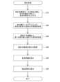
図2は、測定部30が実行する測定処理のフローチャートを示す説明図である。ステップS10では、測定部30は、温度制御部10を制御し、加熱部11による測定対象物TGの上面の加熱と、冷却部13による測定対象物TGの下面の冷却と、を開始する。これにより、測定対象物TGに厚み方向の温度勾配が生じる。 FIG. 2 is an explanatory diagram showing a flowchart of measurement processing executed by the
ステップS20では、測定部30は、赤外線サーモグラフィ25に、測定対象物TGの測定面TSを撮像させる。測定部30の温度演算部31は、赤外線サーモグラフィ25から取得した撮像画像に基づいて測定対象物TGの厚み方向における温度分布を表す温度分布情報を取得する。 In step S20, the
図3は、ステップS20において温度演算部31によって取得される温度分布情報を表すグラフの一例を示す説明図である。温度演算部31によって取得される温度分布情報は、横軸を厚み方向における位置とし、縦軸を赤外線サーモグラフィ25の出力値とするグラフによって表される。「赤外線サーモグラフィ25の出力値」とは、赤外線サーモグラフィ25が出力する撮像画像から取得される温度の測定値を意味する。ここで、一対の試料ブロックBLa,BLbは低放射率の金属によって構成されている。そのため、赤外線サーモグラフィ25によって取得される温度分布情報では、各試料ブロックBLa,BLbの表面温度についての出力値は、実際の温度とは異なった値として得られており、測定対象物TGの温度に比べて著しく低い値が得られる。よって、この温度分布情報を用いれば、測定対象物TGの厚み方向における温度勾配を示す領域と、その両外側にある各試料ブロックBLa,BLbの配置領域とを容易に区別することが可能である。 FIG. 3 is an explanatory diagram showing an example of a graph representing temperature distribution information acquired by the
ステップS30では、測定部30の温度演算部31は、ステップS20で得られた温度分布情報から、第1位置P1での温度と、第2位置P2での温度と、を取得する。本実施形態では、第1位置P1は、測定対象物TGの上面の位置に相当し、第2位置P2は、測定対象物TGの下面の位置に相当する。つまり、本実施形態においては、第1位置P1での温度は、測定対象物TGの温度勾配において最も高い温度である。また、第2位置P2での温度は、測定対象物TGの温度勾配において最も低い温度である。温度演算部31は、温度分布情報を解析して、第1位置P1および第2位置P2を特定する。第1位置P1は、急勾配で温度が上昇する部位と、比較的緩やかな勾配で温度が低下し始める部位との間の頂点の位置である。また、第2位置P2は、温度の低下が比較的緩やかな勾配から急勾配へと変わり始める点の位置である。温度演算部31は、第1位置P1での温度を高温側温度Th[K]として取得する。また、温度演算部31は、第2位置P2での温度を低温側温度Tc[K]として取得する。In step S30, the
ステップS40では、測定部30は、ステップS20で得られた温度分布情報から測定対象物TGの厚みt[m]を取得する。測定部30は、赤外線サーモグラフィ25によって得られた撮像画像におけるステップS30で検出された2つの位置P1,P2の間の画素数と、1画素あたりの既知の寸法と、を用いて、2つの位置P1,P2の間の距離を測定対象物TGの厚みtとして算出する。この方法によれば、固定機構40で荷重がかけられた後の測定対象物TGの厚みtをマイクロスケール等の計測器具を用いることなく、簡易に計測することができる。 In step S40, the
なお、ステップS40では、測定部30は、測定対象物TGの厚みtとして、測定処理の実行前に、マイクロスケール等の計測器具によって計測され、予め入力された値を取得してもよい。測定対象物TGの厚みtは、例えば、以下のように計測することができる。 Note that, in step S40, the
・測定対象物TGの厚みtの計測方法の他の例1:
計測者は、まず、測定対象物TGを挟まない状態で一対の試料ブロックBLa,BLb同士を重ね、両者に予め設けられた目印の間の距離を、マイクロスケール等の計測器具で計測した計測値t0を得る。試料ブロックBLa,BLbの目印は、試料ブロックBLa,BLbの側面に予め設けられた凸部などの構造物でもよいし、試料ブロックBLa,BLbの側面に予めけがきされたマークでもよい。計測器具は、最小読値が0.001mm以下のものであることが望ましい。次に、計測者は、測定対象物TGを固定機構40にセットした状態で、同じ計測器具で、一対の試料ブロックBLa,BLbの目印の間の距離を計測した計測値t1を取得する。こうして得られた2つの計測値t0,t1の差を取ることにより、測定対象物TGの厚みtが算出される(t=t1-t0)。この方法であれば、測定対象物TGが固体でない場合であっても、計測処理の際におけるその厚みtを簡易に計測することができる。・Other example 1 of the method for measuring the thickness t of the measurement target TG:
The measurer first stacks the pair of sample blocks BLa and BLb without sandwiching the object to be measured TG, and then measures the distance between the marks set in advance on both using a measuring instrument such as a microscale. Obtain t0 . The marks for the sample blocks BLa, BLb may be structures such as protrusions provided in advance on the side surfaces of the sample blocks BLa, BLb, or may be marks drawn in advance on the side surfaces of the sample blocks BLa, BLb. It is desirable that the measuring instrument has a minimum reading of 0.001 mm or less. Next, with the object to be measured TG set on the
・測定対象物TGの厚みtの計測方法の他の例2:
測定対象物TGが固体である場合、測定対象物TGの厚みtは、一対の試料ブロックBLa,BLbで挟まれる前に、ノギスやマイクロスケールなどの規則器具により直接的に計測されてもよい。・Other example 2 of the method of measuring the thickness t of the measurement target TG:
When the measurement target TG is solid, the thickness t of the measurement target TG may be directly measured with a regular instrument such as a caliper or a microscale before being sandwiched between the pair of sample blocks BLa and BLb.
ステップS50では、測定部30の熱流演算部33は、一対の熱流センサ21,22のそれぞれの測定結果を用いて、下記の式(1)により、測定対象物TGを厚み方向に流れる通過熱量Q[W]を算出する。 In step S50, the heat

上記の式(1)において、Qh[W]は、第1熱流センサ21による測定熱量であり、Qc[W]は、第2熱流センサ22による測定熱量である。通過熱量Qを、2つの測定熱量Qh,Qcの平均値として求めることにより、各試料ブロックBLa,BLbおよび測定対象物TGの側面からの熱の出入りに起因する誤差が低減される。In the above equation (1), Qh [W] is the amount of heat measured by the first
ステップS60では、測定部30の物性値導出部35は、高温側温度Th[K]、低温側温度Tc[K]、測定対象物TGの厚みt[m]、通過熱量Q[W]、測定対象物TGの上面および下面の面積S[m2]を用いて、下記の式(2)により、熱伝導率λ[W/mK]を算出する。なお、面積Sは、測定処理の開始前に予め計測された既知の値である。In step S60, the physical property

上記の式(2)に示されているように、物性値導出部35は、2つの位置P1,P2のそれぞれの温度Th,Tcの温度差を求め、その温度差と、通過熱量Qと、を用いて熱伝導率λを算出している。ここで、図3に示すように、測定対象物TGの厚み方向における温度勾配を示す領域の両側には、急勾配で変化する2つの過渡領域TAがある。これら2つの過渡領域TAでの温度変化は、温度ギャップとも呼ばれ、各試料ブロックBLa,BLbと測定対象物TGとの間における接触熱抵抗に起因するものである。本実施形態の測定処理であれば、上記のように、そうした温度ギャップを含む過渡領域TAに挟まれた内側の領域で計測された2つの温度Th,Tcを用いて、熱伝導率λが算出されている。そのため、熱伝導率λを、各試料ブロックBLa,BLbと測定対象物TGとの間における接触熱抵抗の影響が抑制された値として得ることができ、測定対象物TGの測定精度が高められている。また、本実施形態の測定処理では、赤外線サーモグラフィ25の撮像画像の解析によって得られる温度分布情報を用いているため、それら2つの温度Th,Tcを精度よく簡易に検出することが容易である。As shown in the above equation (2), the physical property
以上のように、第1実施形態における測定システム100および測定方法によれば、赤外線サーモグラフィ25を用いた簡易な方法により、測定対象物TGの熱伝導率の測定精度が高められている。また、上記のように、第1実施形態における測定システム100およびその測定方法によれば、少なくとも1度の測定処理により、熱伝導率λを、各試料ブロックBLa,BLbと測定対象物TGとの間における接触熱抵抗の影響が抑制された値として得ることができる。そのため、接触熱抵抗に起因する誤差を低減するために、厚みの異なる測定対象物TGの測定を行うなどの誤差対策の手間やコストを低減することが可能である。また、厚みの異なる測定対象物TGごとの測定を行わなくてもよくなることにより、厚みの異なる測定対象物TGごとの測定結果のばらつきに起因して生じる測定誤差の拡大を抑制することもできる。 As described above, according to the
2.第2実施形態:
図4は、第2実施形態における測定処理のフローチャートを示す説明図である。第2実施形態の測定処理は、第1実施形態で説明した図1に示す測定システム100において実行される。第2実施形態の測定処理は、ステップS30の処理の代わりにステップS35の処理が実行される点と、ステップS40が省略されている点と、ステップS60において使用される数式が異なる点以外は、第1実施形態の測定処理とほぼ同じである。2. Second embodiment:
FIG. 4 is an explanatory diagram showing a flowchart of measurement processing in the second embodiment. The measurement process of the second embodiment is executed in the
以下では、まず、測定対象物TGが固体の均質材料であり、厚み方向における熱伝導率が一定である場合について説明する。ステップS10~S20では、第1実施形態で説明したのと同様の処理が実行される。 In the following, first, a case will be described where the measurement target TG is a solid homogeneous material and the thermal conductivity in the thickness direction is constant. In steps S10 to S20, processing similar to that described in the first embodiment is executed.
図5は、ステップS35において実行される処理を説明するための説明図である。図5には、測定部30の温度演算部31によって取得される温度分布情報を表すグラフの一例が図示されている。ステップS35では、温度演算部31は、赤外線サーモグラフィ25の撮像画像から得られた温度分布情報を用いて、測定対象物TGの厚み方向における温度勾配を取得する。温度演算部31は、測定対象物TGの厚み方向における予め定められた基準位置CPを中心とする予め定められた範囲内における複数の測定点での温度の計測値を用いて、最小二乗法により、その範囲内での温度勾配aを算出する。温度勾配aは、位置に対する温度の変化率を意味する。基準位置CPは、測定対象物TGの厚み方向における中央付近の位置であることが望ましい。また、温度勾配aの算出には、30点以上の測定点での温度の計測値が用いられることが望ましい。 FIG. 5 is an explanatory diagram for explaining the process executed in step S35. FIG. 5 shows an example of a graph representing temperature distribution information acquired by the
ステップS50では、測定部30は、第1実施形態で説明したのと同様に、測定対象物TGにおける通過熱量Qを取得する。ステップS60では、物性値導出部35は、下記の式(3)に、ステップS35で取得した温度勾配aと、通過熱量Qと、測定対象物TGの上面および下面の面積Sと、を代入して、熱伝導率λを算出する。なお、式(3)は、その過程の式に示されているように、(Th-Tc)/tを温度勾配aとみなすことにより、式(2)から導出される。In step S50, the

図6を参照して、測定対象物TGの熱伝導率に温度依存性がある場合について説明する。図6には、測定対象物TGの温度分布情報を表すグラフの一例が図示されている。測定対象物TGの熱伝導率に温度依存性がある場合には、温度勾配aは、測定対象物TGの厚み方向における位置ごとに変化する。この場合には、各位置P1,P2,P3,・・・における温度勾配a1,a2,a3,・・・を取得することにより、上記の式(3)を用いて、測定対象物TGの温度ごとの熱伝導率λを求めることができる。With reference to FIG. 6, a case will be described in which the thermal conductivity of the measurement target TG has temperature dependence. FIG. 6 shows an example of a graph representing temperature distribution information of the measurement target TG. When the thermal conductivity of the measurement target TG has temperature dependence, the temperature gradient a changes for each position in the thickness direction of the measurement target TG. In this case, by obtaining the temperature gradientsa 1, a2 , a3 , . . . at each position P 1 , P2 , P3 , . . . using the above equation (3), The thermal conductivity λ for each temperature of the measurement target TG can be determined.
以上のように、第2実施形態の測定システム100および測定方法によれば、赤外線サーモグラフィ25によって取得した温度分布情報から温度勾配を求めることにより、測定対象物TGの熱伝導率を、簡易に、精度よく測定することができる。 As described above, according to the
3.第3実施形態:
図7は、第3実施形態における測定システム100Aの構成を示す概略図である。第3実施形態の測定システム100Aは、各試料ブロックBLa,BLbに複数の温度センサ27が取り付けられている点以外は、第1実施形態で説明した測定システム100の構成とほぼ同じである。3. Third embodiment:
FIG. 7 is a schematic diagram showing the configuration of a
温度センサ27は、各試料ブロックBLa,BLbに、例えば3つずつ取り付けられる。なお、温度センサ27の個数は3つでなくともよく、1つでもよいし、2つもしくは4つ以上であってもよい。各温度センサ27は、例えば熱電対によって構成される。熱電対としては、測定精度として±1.5℃以内の許容差のものが望ましく、JIS C 1602-1995の規格におけるK型クラス1の性能、もしくはそれ以上の性能を有するものが望ましい。各温度センサ27は、各試料ブロックBLa,BLbにおいて、測定対象物TGとの界面からの距離tcの位置に設けられた孔の中に挿入される。孔の位置は、各試料ブロックBLa,BLbの形状に応じて適宜定められればよい。For example, three
第3実施形態の測定システム100Aでは、測定部30は、第1実施形態で説明した図2の測定処理によって熱伝導率λを算出した後に、測定対象物TGの熱伝導に関する物性値である熱接触抵抗Rを、温度センサ27の計測値を用いて測定する。なお、測定システム100Aは、第1実施形態の測定処理に代えて、第2実施形態で説明した図4に示す測定処理によって測定対象物TGの熱伝導率λを算出してもよい。 In the
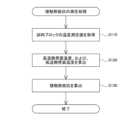
図8は、測定システム100Aで実行される接触熱抵抗の測定処理のフローチャートを示す説明図である。ステップS110では、測定部30の温度演算部31が、各試料ブロックBLa,BLbに設けられている温度センサ27によって計測される温度の計測値を取得する。 FIG. 8 is an explanatory diagram showing a flowchart of a contact thermal resistance measurement process executed by the
ステップS120では、温度演算部31は、各計測値を用いて、下記の式(4)および(5)により、高温側界面温度Thb[K]および低温側界面温度Tcb[K]を算出する。高温側界面温度Thbは、第1試料ブロックBLaと測定対象物TGとの間の界面における温度に相当する。低温側界面温度Tcbは、第2試料ブロックBLbと測定対象物TGとの間の界面における温度に相当する。In step S120, the


上記の式(4)において、Th1[K],Th2[K],Th3[K]はそれぞれ、第1試料ブロックBLaに設けられた3つの温度センサ27による計測値である。上記の式(5)において、Tc1[K],Tc2[K],Tc3[K]はそれぞれ、第2試料ブロックBLbに設けられた3つの温度センサ27による計測値である。また、上記の式(4),(5)において、tc[m]は、各試料ブロックBLa,BLbと測定対象物TGの界面から温度センサ27までの距離である。S[m2]は測定対象物TGの上面および下面の面積、つまり、各試料ブロックBLa,BLbの底面または上面の面積である。λc[W/mK]は、各試料ブロックBLa,BLbの構成材料の熱伝導率である。λcは、公称値でもよいし、文献値、あるいは、実測値であってもよい。Qh[W]は、第1熱流センサ21による計測値であり、Qc[W]は、第2熱流センサ22の計測値である。In the above equation (4), Th1 [K], Th2 [K], and Th3 [K] are values measured by the three
ステップS130では、測定部30の物性値導出部35が、ステップS120で取得された高温側界面温度Thbおよび低温側界面温度Tcbと、先に算出された測定対象物TGの熱伝導率λ[W/mK]と、を用いて、接触熱抵抗R[Km2/W]を算出する。物性値導出部35は、下記の式(6)を用いて、接触熱抵抗Rを算出する。In step S130, the physical property

上記の式(6)におけるQ[W]は、第1実施形態で説明した、一対の熱流センサ21,22の計測値から求められた通過熱量Qと同じである。S[m2]は測定対象物TGの面積である。tm[m]は、測定対象物TGの厚みであるが、第1実施形態で説明した赤外線サーモグラフィ25の撮像画像に基づいて算出された値ではなく、計測器具を用いた計測により得られる実測値である。Q[W] in the above equation (6) is the same as the amount of passed heat Q determined from the measured values of the pair of
第3実施形態の測定システム100Aおよび測定方法によれば、赤外線サーモグラフィ25を用いることにより、測定対象物TGの熱伝導に関する物性値として、熱伝導率のみだけではなく、接触熱抵抗を、簡易な方法で、精度よく測定することができる。測定対象物TGの接触熱抵抗が精度よく測定できれば、測定対象物TGの放熱性についての評価の精度をより高めることができる。 According to the
4.他の実施形態:
本開示の技術は、上述の実施形態に限られるものではなく、その趣旨を逸脱しない範囲において種々の構成で実現することができる。例えば、上述の課題の一部又は全部を解決するために、あるいは、上述の効果の一部又は全部を達成するために、適宜、差し替えや、組み合わせを行うことが可能である。また、上記実施形態で説明した種々の構成は、例えば、以下のように改変することが可能である。以下に説明する構成はいずれも、上記実施形態と同様に、本開示の技術を実施するための実施形態の一例として位置づけられる。
・上記の第1実施形態において、測定対象物TGの熱伝導率λが温度依存性を有しておらず、厚み方向に均一である場合、高温側温度Thと低温側温度Tcは、測定対象物TGの厚み方向における上面および下面の温度でなくてもよい。高温側温度Thと低温側温度Tcとは、測定対象物TGにおいて厚み方向に並ぶ予め定められた任意の2つの位置P1,P2での温度であってもよい。ただし、その任意の2つの位置P1,P2間の距離は大きいほど望ましい。なお、この構成によれば、温度分布情報において、一対の試料ブロックBLa,BLbの領域と測定対象物TGの領域との境界を求めなくともよいため、一対の試料ブロックBLa,BLbを省略することも可能である。
・一対の試料ブロックBLa,BLbは、Cu以外の他の金属で構成されてもよい。また、一対の試料ブロックBLa,BLbは矩形形状以外の形状を有していてもよい。一対の試料ブロックBLa,BLbは多角柱形状を有していてもよい。この場合には、測定対象物TGの形状も試料ブロックBLa,BLbに合わせて成形されることが望ましい。上記の第2実施形態では、一対の試料ブロックBLa,BLbは、省略されてもよい。
・上記の実施形態において、加熱部11や冷却部13は、上記実施形態で説明した以外の方法で測定対象物TGの加熱や冷却を実行してもよい。加熱部11や冷却部13は、例えば、ペルチェ素子によって構成されてもよい。
・上記の実施形態において、測定システム100,100Aは、測定結果である物性値を出力する出力部を備えていてもよい。また、測定システム100,100Aの測定部30は、測定に関する演算のみを実行し、測定システム100,100Aの制御は実行しないものとしてもよい。4. Other embodiments:
The technology of the present disclosure is not limited to the above-described embodiments, and can be implemented in various configurations without departing from the spirit thereof. For example, in order to solve some or all of the above-mentioned problems or to achieve some or all of the above-mentioned effects, it is possible to perform appropriate replacements or combinations. Further, the various configurations described in the above embodiments can be modified as follows, for example. All of the configurations described below are positioned as examples of embodiments for implementing the technology of the present disclosure, similarly to the above embodiments.
- In the first embodiment described above, if the thermal conductivity λ of the measurement target TG has no temperature dependence and is uniform in the thickness direction, the high temperature side temperature Th and the low temperature side temperature Tc are It does not have to be the temperature of the upper surface and lower surface in the thickness direction of the measurement target TG. The high temperature Th and the low temperature Tc may be temperatures at any two predetermined positions P1 and P2 arranged in the thickness direction of the measurement target TG. However, it is desirable that the distance between the two arbitrary positions P1 and P2 be as large as possible. Note that according to this configuration, in the temperature distribution information, there is no need to determine the boundary between the area of the pair of sample blocks BLa, BLb and the area of the measurement target TG, so the pair of sample blocks BLa, BLb can be omitted. is also possible.
- The pair of sample blocks BLa and BLb may be made of metal other than Cu. Further, the pair of sample blocks BLa and BLb may have a shape other than a rectangular shape. The pair of sample blocks BLa and BLb may have a polygonal column shape. In this case, it is desirable that the shape of the object to be measured TG is also molded to match the sample blocks BLa, BLb. In the second embodiment described above, the pair of sample blocks BLa and BLb may be omitted.
- In the above embodiment, the heating unit 11 and the cooling unit 13 may heat or cool the measurement target TG using methods other than those described in the above embodiment. The heating unit 11 and the cooling unit 13 may be configured by, for example, a Peltier element.
- In the embodiments described above, the
100,100A…測定システム、10…温度制御部、11…加熱部、12…高温側温度制御部、13…冷却部、14…低温側温度制御部、21…第1熱流センサ、22…第2熱流センサ、25…赤外線サーモグラフィ、27…温度センサ、30…測定部、31…温度演算部、33…熱流演算部、35…物性値導出部、40…固定機構、41…天板、42…押圧板、43…底板、45…荷重機構、46…ハンドル、47…ネジ部、BLa…第1試料ブロック、BLb…第2試料ブロック、TA…過渡領域、TG…測定対象物、TS…測定面100, 100A...Measurement system, 10...Temperature control section, 11...Heating section, 12...High temperature side temperature control section, 13...Cooling section, 14...Low temperature side temperature control section, 21...First heat flow sensor, 22...Second Heat flow sensor, 25... Infrared thermography, 27... Temperature sensor, 30... Measurement section, 31... Temperature calculation section, 33... Heat flow calculation section, 35... Physical property value derivation section, 40... Fixing mechanism, 41... Top plate, 42... Pressure Plate, 43...Bottom plate, 45...Loading mechanism, 46...Handle, 47...Screw part, BLa...First sample block, BLb...Second sample block, TA...Transient area, TG...Measurement object, TS...Measurement surface
Claims (8)
Translated fromJapanese前記測定対象物の厚み方向における一方の面を加熱するとともに他方の面を冷却して、前記測定対象物に前記厚み方向の温度勾配を生じさせる工程と、
赤外線サーモグラフィによって前記測定対象物の前記厚み方向における温度分布情報を取得する工程と、
前記測定対象物の前記厚み方向に流れる熱量を測定する工程と、
前記温度分布情報と前記熱量とを用いて、前記物性値としての熱伝導率を算出する工程と、
を備える、方法。A method for measuring physical property values related to thermal conduction of a measurement target, the method comprising:
heating one surface in the thickness direction of the measurement object and cooling the other surface to generate a temperature gradient in the thickness direction of the measurement object;
acquiring temperature distribution information in the thickness direction of the measurement target by infrared thermography;
measuring the amount of heat flowing in the thickness direction of the measurement target;
calculating thermal conductivity as the physical property value using the temperature distribution information and the amount of heat;
A method of providing.
前記温度分布情報から、前記測定対象物において前記厚み方向に並ぶ第1位置と第2位置の間の温度差を求め、前記温度差と前記熱量とを用いて前記熱伝導率を算出する、方法。The method according to claim 1, comprising:
A method of determining a temperature difference between a first position and a second position lined up in the thickness direction of the object to be measured from the temperature distribution information, and calculating the thermal conductivity using the temperature difference and the amount of heat. .
前記温度分布情報から前記測定対象物の前記厚み方向における所定の範囲内における温度の変化率を求め、前記変化率と前記熱量とを用いて前記熱伝導率を算出する、方法。The method according to claim 1, comprising:
A method of determining a rate of change in temperature within a predetermined range in the thickness direction of the object to be measured from the temperature distribution information, and calculating the thermal conductivity using the rate of change and the amount of heat.
前記温度勾配を生じさせる工程は、前記測定対象物の前記一方の面を、第1試料ブロックを介して加熱するとともに、前記測定対象物の前記他方の面を、第2試料ブロックを介して冷却する工程を含み、
前記方法は、さらに、
前記測定対象物と前記第1試料ブロックとの界面における高温側界面温度と、前記測定対象物と前記第2試料ブロックとの界面における低温側界面温度と、を取得する工程と、
前記高温側界面温度と、前記低温側界面温度と、先に算出された前記測定対象物の前記熱伝導率と、を用いて、前記物性値としての接触熱抵抗を算出する工程と、
を備える、方法。The method according to any one of claims 1 to 3,
The step of generating a temperature gradient includes heating the one surface of the object to be measured via a first sample block, and cooling the other surface of the object to be measured via a second sample block. including the process of
The method further includes:
obtaining a high temperature side interface temperature at the interface between the measurement object and the first sample block and a low temperature side interface temperature at the interface between the measurement object and the second sample block;
calculating a contact thermal resistance as the physical property value using the high temperature side interface temperature, the low temperature side interface temperature, and the previously calculated thermal conductivity of the measurement object;
A method of providing.
前記測定対象物の厚み方向における一方の面を加熱する加熱部と、他方の面を冷却する冷却部と、を有し、前記測定対象物に前記厚み方向の温度勾配を生じさせる温度制御部と、
前記測定対象物の前記厚み方向に流れる熱量を測定する熱流センサと、
前記測定対象物の前記厚み方向における温度分布を表す画像を撮影する赤外線サーモグラフィと、
前記赤外線サーモグラフィの撮影結果から前記測定対象物の温度分布情報を取得し、前記温度分布情報と、前記熱流センサによって測定された前記熱量と、を用いて、前記物性値としての熱伝導率を算出する測定部と、
を備える、測定システム。A measurement system for measuring physical property values related to thermal conduction of a measurement target,
a temperature control section that includes a heating section that heats one surface of the measurement object in the thickness direction and a cooling section that cools the other surface of the measurement object, and that generates a temperature gradient in the thickness direction of the measurement object; ,
a heat flow sensor that measures the amount of heat flowing in the thickness direction of the measurement target;
an infrared thermography camera that captures an image representing the temperature distribution in the thickness direction of the measurement target;
Obtaining temperature distribution information of the object to be measured from the photographic results of the infrared thermography, and calculating thermal conductivity as the physical property value using the temperature distribution information and the amount of heat measured by the heat flow sensor. a measuring section to
A measurement system comprising:
前記測定部は、前記温度分布情報から、前記測定対象物において前記厚み方向に並ぶ第1位置と第2位置の間の温度差を求め、前記温度差と前記熱量とを用いて前記熱伝導率を算出する、測定システム。6. The measurement system according to claim 5,
The measurement unit calculates a temperature difference between a first position and a second position arranged in the thickness direction of the object to be measured from the temperature distribution information, and calculates the thermal conductivity using the temperature difference and the amount of heat. A measurement system that calculates.
前記測定部は、前記温度分布情報から前記測定対象物の前記厚み方向における所定の範囲内における温度の変化率を求め、前記変化率と前記熱量とを用いて前記熱伝導率を算出する、測定システム。6. The measurement system according to claim 5,
The measurement unit determines a rate of change in temperature within a predetermined range in the thickness direction of the object to be measured from the temperature distribution information, and calculates the thermal conductivity using the rate of change and the amount of heat. system.
前記加熱部は、前記一方の面に接した状態で配置される第1試料ブロックを介して前記測定対象物を加熱し、
前記冷却部は、前記他方の面に接した状態で配置される第2試料ブロックを介して前記測定対象物を冷却し、
前記測定システムは、さらに、前記第1試料ブロックと前記第2試料ブロックのそれぞれの温度を計測する温度センサを備え、
前記測定部は、前記温度センサを用いて、前記測定対象物と前記第1試料ブロックとの界面における温度を表す高温側界面温度と、前記測定対象物と前記第2試料ブロックとの界面における温度を表す低温側界面温度と、を取得し、
前記高温側界面温度と、前記低温側界面温度と、先に算出した前記測定対象物の前記熱伝導率と、を用いて、前記物性値としての接触熱抵抗を算出する、測定システム。
The measurement system according to any one of claims 5 to 7,
The heating unit heats the measurement target via a first sample block placed in contact with the one surface,
The cooling unit cools the measurement target via a second sample block placed in contact with the other surface,
The measurement system further includes a temperature sensor that measures the temperature of each of the first sample block and the second sample block,
The measurement unit uses the temperature sensor to measure a high-temperature side interface temperature representing the temperature at the interface between the measurement object and the first sample block, and a temperature at the interface between the measurement object and the second sample block. Obtain the cold side interface temperature, which represents
A measurement system that calculates contact thermal resistance as the physical property value using the high-temperature side interface temperature, the low-temperature side interface temperature, and the previously calculated thermal conductivity of the measurement object.
Priority Applications (1)
| Application Number | Priority Date | Filing Date | Title |
|---|---|---|---|
| JP2020089573AJP7376875B2 (en) | 2020-05-22 | 2020-05-22 | Method and system for measuring physical property values related to thermal conduction of a measurement target |
Applications Claiming Priority (1)
| Application Number | Priority Date | Filing Date | Title |
|---|---|---|---|
| JP2020089573AJP7376875B2 (en) | 2020-05-22 | 2020-05-22 | Method and system for measuring physical property values related to thermal conduction of a measurement target |
Publications (2)
| Publication Number | Publication Date |
|---|---|
| JP2021183943A JP2021183943A (en) | 2021-12-02 |
| JP7376875B2true JP7376875B2 (en) | 2023-11-09 |
Family
ID=78767293
Family Applications (1)
| Application Number | Title | Priority Date | Filing Date |
|---|---|---|---|
| JP2020089573AActiveJP7376875B2 (en) | 2020-05-22 | 2020-05-22 | Method and system for measuring physical property values related to thermal conduction of a measurement target |
Country Status (1)
| Country | Link |
|---|---|
| JP (1) | JP7376875B2 (en) |
Families Citing this family (19)
| Publication number | Priority date | Publication date | Assignee | Title |
|---|---|---|---|---|
| KR102494392B1 (en)* | 2021-07-06 | 2023-01-31 | 현대로템 주식회사 | Stator Segment Heat Transfer Characteristics Test Device for Electric Machine |
| CN114384116A (en)* | 2021-12-24 | 2022-04-22 | 大连理工大学 | A high-efficiency testing device and method for interface contact thermal resistance under high temperature conditions |
| PL446179A1 (en)* | 2023-09-19 | 2024-07-29 | Politechnika Śląska | Stand for testing thermal conductivity, especially of non-homogeneous materials |
| PL446182A1 (en)* | 2023-09-19 | 2024-07-29 | Politechnika Śląska | Station for measuring thermal conductivity and contact heat flow resistance using thermography |
| PL446176A1 (en)* | 2023-09-19 | 2024-07-29 | Politechnika Śląska | Method of measuring temperature distribution in tests of contact heat flow resistance and thermal conductivity and a system for implementing this method |
| PL446174A1 (en)* | 2023-09-19 | 2024-07-29 | Politechnika Śląska | Measuring device for determining thermal conductivity, especially of composite materials with a polymer matrix |
| PL446165A1 (en)* | 2023-09-19 | 2024-06-17 | Politechnika Śląska | Device for analysing thermal conductivity, especially of non-homogeneous materials |
| PL446166A1 (en)* | 2023-09-19 | 2024-06-17 | Politechnika Śląska | Device for analysing contact heat flow resistance and thermal conductivity |
| PL446168A1 (en)* | 2023-09-19 | 2024-07-29 | Politechnika Śląska | Sliding thermal insulation assembly and a station for analysing heat flow using the thermographic method, containing a sliding thermal insulation assembly |
| PL446181A1 (en)* | 2023-09-19 | 2024-07-29 | Politechnika Śląska | Station for measuring thermal parameters using the thermographic method |
| PL446164A1 (en)* | 2023-09-19 | 2024-07-29 | Politechnika Śląska | Device for testing thermal conductivity using the thermographic method |
| PL446183A1 (en)* | 2023-09-19 | 2024-07-29 | Politechnika Śląska | Stand for testing contact heat flow resistance and thermal conductivity |
| PL446170A1 (en)* | 2023-09-19 | 2024-07-29 | Politechnika Śląska | Laboratory stand for testing thermal conductivity and contact heat flow resistance |
| PL446167A1 (en)* | 2023-09-19 | 2024-06-17 | Politechnika Śląska | Device for measuring thermal conductivity and contact heat flow resistance using thermography |
| PL446180A1 (en)* | 2023-09-19 | 2024-07-15 | Politechnika Śląska | Stand for testing thermal conductivity using the thermographic method |
| PL446177A1 (en)* | 2023-09-19 | 2024-07-29 | Politechnika Śląska | Laboratory stand for measuring thermal conductivity, especially of non-homogeneous materials |
| PL446173A1 (en)* | 2023-09-19 | 2024-07-29 | Politechnika Śląska | Measuring device for determining thermal conductivity, especially of non-homogeneous materials |
| PL448070A1 (en)* | 2024-03-21 | 2024-10-21 | Politechnika Śląska | Thermal conductivity measurement station |
| CN119199459B (en)* | 2024-11-27 | 2025-03-11 | 深圳市欣博跃电子有限公司 | Method, system, device and storage medium for measuring chip thermal resistance |
Citations (6)
| Publication number | Priority date | Publication date | Assignee | Title |
|---|---|---|---|---|
| US6142662A (en) | 1998-06-16 | 2000-11-07 | New Jersey Institute Of Technology | Apparatus and method for simultaneously determining thermal conductivity and thermal contact resistance |
| JP2003121397A (en) | 2001-10-10 | 2003-04-23 | Hitachi Ltd | Method for measuring thermal resistance of resin and measuring device using the method |
| JP2004325141A (en) | 2003-04-22 | 2004-11-18 | Rikogaku Shinkokai | Thermal analysis method and thermal analysis device |
| JP2011102768A (en) | 2009-11-11 | 2011-05-26 | Canon Inc | Measuring method of heat characteristic |
| JP2012117939A (en) | 2010-12-01 | 2012-06-21 | Espec Corp | Heat conductivity measuring device, heat conductivity calculation device, heat conductivity calculation program, and heat conductivity measuring method |
| CN109001252A (en) | 2018-06-28 | 2018-12-14 | 西南电子技术研究所(中国电子科技集团公司第十研究所) | Test device of thermal conductivity coefficient |
Family Cites Families (1)
| Publication number | Priority date | Publication date | Assignee | Title |
|---|---|---|---|---|
| JPH0718826B2 (en)* | 1990-02-14 | 1995-03-06 | 工業技術院長 | Thermal conductivity measurement method |
- 2020
- 2020-05-22JPJP2020089573Apatent/JP7376875B2/enactiveActive
Patent Citations (6)
| Publication number | Priority date | Publication date | Assignee | Title |
|---|---|---|---|---|
| US6142662A (en) | 1998-06-16 | 2000-11-07 | New Jersey Institute Of Technology | Apparatus and method for simultaneously determining thermal conductivity and thermal contact resistance |
| JP2003121397A (en) | 2001-10-10 | 2003-04-23 | Hitachi Ltd | Method for measuring thermal resistance of resin and measuring device using the method |
| JP2004325141A (en) | 2003-04-22 | 2004-11-18 | Rikogaku Shinkokai | Thermal analysis method and thermal analysis device |
| JP2011102768A (en) | 2009-11-11 | 2011-05-26 | Canon Inc | Measuring method of heat characteristic |
| JP2012117939A (en) | 2010-12-01 | 2012-06-21 | Espec Corp | Heat conductivity measuring device, heat conductivity calculation device, heat conductivity calculation program, and heat conductivity measuring method |
| CN109001252A (en) | 2018-06-28 | 2018-12-14 | 西南电子技术研究所(中国电子科技集团公司第十研究所) | Test device of thermal conductivity coefficient |
Also Published As
| Publication number | Publication date |
|---|---|
| JP2021183943A (en) | 2021-12-02 |
Similar Documents
| Publication | Publication Date | Title |
|---|---|---|
| JP7376875B2 (en) | Method and system for measuring physical property values related to thermal conduction of a measurement target | |
| JP5509195B2 (en) | Thermal conductivity measuring device and thermal conductivity measuring method | |
| JP6682016B2 (en) | Thermal conductivity measuring device and thermal conductivity measuring method | |
| EP3567367B1 (en) | Steady-state test method for heat-conducting property in the direction along plane of sheet material | |
| CN109490355A (en) | A kind of method of test device of thermal conductivity coefficient and heat conducting coefficient measuring | |
| JP2008309729A (en) | Thermal conductivity measuring device and thermal conductivity measuring method | |
| CN101290299A (en) | A measuring device and method for variable thermal conductivity | |
| JPS63179266A (en) | Method for measuring thermal resistance of elements such as components with high-density integrated circuits, and apparatus for carrying out the measuring method | |
| CN108351313A (en) | Heat conductivity measuring device and thermal conductivity measurement method | |
| CN115389551B (en) | System and method for testing heat dissipation characteristics of film material | |
| JP2006145446A (en) | Thermal conductivity measuring device and thermal conductivity measuring method | |
| JP2011102768A (en) | Measuring method of heat characteristic | |
| US20100202488A1 (en) | Apparatus And A Method For Measuring The Body Core Temperature For Elevated Ambient Temperatures | |
| CN114544699B (en) | Method for testing thermal resistance and thermal conductivity coefficient of material | |
| Solbrekken et al. | The development of a tool to predict package level thermal interface material performance | |
| US20220128497A1 (en) | A measurement mechanism | |
| TWI570412B (en) | Thermal needle probe | |
| WO2025111706A1 (en) | Systems and methods for measuring thermal behaviour of materials | |
| KR102257190B1 (en) | Thermal conductivity measurement system and thermal conductivity measurement method thereof | |
| CN103543174B (en) | Testing method and system of junction-loop thermal resistance | |
| JP7217401B2 (en) | Calorific value measuring method and calorific value measuring device | |
| KR101221972B1 (en) | Gauge for measuring heat flux having double row | |
| Yao et al. | Calibration method and uncertainty assessment of a high-temperature GHP apparatus | |
| Lehtiniemi et al. | Applications of infrared thermography in electronics research | |
| SU1073663A1 (en) | Material thermal physical characteristic complex determination method |
Legal Events
| Date | Code | Title | Description |
|---|---|---|---|
| A621 | Written request for application examination | Free format text:JAPANESE INTERMEDIATE CODE: A621 Effective date:20230314 | |
| A977 | Report on retrieval | Free format text:JAPANESE INTERMEDIATE CODE: A971007 Effective date:20230915 | |
| TRDD | Decision of grant or rejection written | ||
| A01 | Written decision to grant a patent or to grant a registration (utility model) | Free format text:JAPANESE INTERMEDIATE CODE: A01 Effective date:20230926 | |
| A61 | First payment of annual fees (during grant procedure) | Free format text:JAPANESE INTERMEDIATE CODE: A61 Effective date:20231018 | |
| R150 | Certificate of patent or registration of utility model | Ref document number:7376875 Country of ref document:JP Free format text:JAPANESE INTERMEDIATE CODE: R150 |