JP7369850B2 - Underfloor space insulation structure and manufacturing method for underfloor space insulation structure - Google Patents
Underfloor space insulation structure and manufacturing method for underfloor space insulation structureDownload PDFInfo
- Publication number
- JP7369850B2 JP7369850B2JP2022196207AJP2022196207AJP7369850B2JP 7369850 B2JP7369850 B2JP 7369850B2JP 2022196207 AJP2022196207 AJP 2022196207AJP 2022196207 AJP2022196207 AJP 2022196207AJP 7369850 B2JP7369850 B2JP 7369850B2
- Authority
- JP
- Japan
- Prior art keywords
- bag
- underfloor space
- heat insulating
- underfloor
- sheet body
- Prior art date
- Legal status (The legal status is an assumption and is not a legal conclusion. Google has not performed a legal analysis and makes no representation as to the accuracy of the status listed.)
- Active
Links
- 238000009413insulationMethods0.000titleclaimsdescription43
- 238000004519manufacturing processMethods0.000titleclaimsdescription19
- 238000009423ventilationMethods0.000claimsdescription95
- 239000011810insulating materialSubstances0.000claimsdescription58
- 238000000034methodMethods0.000claimsdescription52
- 230000000630rising effectEffects0.000claimsdescription42
- 238000003780insertionMethods0.000claimsdescription9
- 230000037431insertionEffects0.000claimsdescription9
- 239000000203mixtureSubstances0.000claimsdescription9
- 239000012530fluidSubstances0.000claimsdescription7
- 238000009434installationMethods0.000claimsdescription7
- 238000007599dischargingMethods0.000claimsdescription4
- 238000007664blowingMethods0.000claimsdescription2
- 238000005096rolling processMethods0.000claims1
- 238000009418renovationMethods0.000description11
- 239000004744fabricSubstances0.000description10
- 239000000463materialSubstances0.000description8
- 238000003466weldingMethods0.000description7
- 238000010276constructionMethods0.000description6
- 230000001143conditioned effectEffects0.000description4
- 229920000742CottonPolymers0.000description3
- 239000004698PolyethyleneSubstances0.000description3
- 239000002390adhesive tapeSubstances0.000description3
- 238000010438heat treatmentMethods0.000description3
- 239000012774insulation materialSubstances0.000description3
- -1polyethylenePolymers0.000description3
- 229920000573polyethylenePolymers0.000description3
- 239000011347resinSubstances0.000description3
- 229920005989resinPolymers0.000description3
- VYPSYNLAJGMNEJ-UHFFFAOYSA-NSilicium dioxideChemical compoundO=[Si]=OVYPSYNLAJGMNEJ-UHFFFAOYSA-N0.000description2
- 230000007423decreaseEffects0.000description2
- 238000009408flooringMethods0.000description2
- 238000007689inspectionMethods0.000description2
- 238000005192partitionMethods0.000description2
- 230000002093peripheral effectEffects0.000description2
- 238000004804windingMethods0.000description2
- 229920003043Cellulose fiberPolymers0.000description1
- 241000256602IsopteraSpecies0.000description1
- 239000005909KieselgurSubstances0.000description1
- 241001465754MetazoaSpecies0.000description1
- 229910000831SteelInorganic materials0.000description1
- 229920002522Wood fibrePolymers0.000description1
- 241000607479Yersinia pestisSpecies0.000description1
- 238000005452bendingMethods0.000description1
- 239000004568cementSubstances0.000description1
- 238000009833condensationMethods0.000description1
- 230000005494condensationEffects0.000description1
- 238000001816coolingMethods0.000description1
- 238000005520cutting processMethods0.000description1
- 238000005516engineering processMethods0.000description1
- 239000000835fiberSubstances0.000description1
- 238000005429filling processMethods0.000description1
- 230000009969flowable effectEffects0.000description1
- 238000007710freezingMethods0.000description1
- 230000008014freezingEffects0.000description1
- 239000011491glass woolSubstances0.000description1
- 239000000077insect repellentSubstances0.000description1
- 239000007788liquidSubstances0.000description1
- 239000011490mineral woolSubstances0.000description1
- 238000012986modificationMethods0.000description1
- 230000004048modificationEffects0.000description1
- 239000000741silica gelSubstances0.000description1
- 229910002027silica gelInorganic materials0.000description1
- 239000010959steelSubstances0.000description1
- 230000032258transportEffects0.000description1
- XLYOFNOQVPJJNP-UHFFFAOYSA-NwaterSubstancesOXLYOFNOQVPJJNP-UHFFFAOYSA-N0.000description1
- 239000002025wood fiberSubstances0.000description1
- 210000002268woolAnatomy0.000description1
Images


Landscapes
- Building Environments (AREA)
- Working Measures On Existing Buildindgs (AREA)
Description
Translated fromJapanese本発明は、建物の床下を断熱するための床下空間の断熱構造および床下空間の断熱構造の製造方法に関するものである。 The present invention relates to an underfloor space insulation structure for insulating the underfloor space of a building, and a method for manufacturing the underfloor space insulation structure.
近年、建物の居住環境の改善とエネルギー効率の改善を目的として、建物の床下の断熱性を向上するための床下断熱構造が知られている(例えば、特許文献1)。この床下断熱構造は、床材の下面と地面(コンクリート面)との間に板状の断熱材を配置して床下の断熱を実現している。 In recent years, an underfloor insulation structure for improving the insulation under the floor of a building has been known for the purpose of improving the living environment and energy efficiency of the building (for example, Patent Document 1). This underfloor insulation structure achieves insulation under the floor by placing a plate-shaped insulation material between the bottom surface of the flooring material and the ground (concrete surface).
床断熱が施工されていない既存建物の断熱性能を向上させるために、床下に断熱材を設置する床断熱リフォームが行われる。特許文献1に記載された技術は、新築の建物に対して床下断熱構造の施工を行うことが想定されており、既存の建物の床断熱リフォームに適用しようとすると、床材を剥がす等の大掛かりな施工が必要となり、工期が長くなると共に、施工費も高くなる可能性がある。 In order to improve the insulation performance of existing buildings that do not have floor insulation installed, floor insulation renovation is carried out by installing insulation material under the floor. The technology described in
そこで、本発明は、上述した事情に考慮してなされたものであり、既存の建物に床からの熱損失を低減して断熱性能を向上させるための床断熱リフォームを簡便に施工することができる、床下空間の断熱構造および床下空間の断熱構造の製造方法を提供することを目的とする。 Therefore, the present invention has been made in consideration of the above-mentioned circumstances, and enables floor insulation renovation to be easily carried out in an existing building to reduce heat loss from the floor and improve insulation performance. An object of the present invention is to provide an insulating structure for an underfloor space and a method for manufacturing the insulating structure for an underfloor space.
上記課題を解決するために、本発明は以下の態様を採用した。
本発明の一態様に係る床下空間の断熱構造は、内部に断熱材が充填された状態で柱状に膨張したチューブ状の袋体と、前記袋体の一辺に取り付けられたガイド棒と、を備える断熱部材により構成され、前記袋体および前記ガイド棒は、床下空間において前記床下空間の外周に沿った基礎の立上り部に並置される。
本発明の一態様に係る床下空間の断熱構造は、前記ガイド棒は、前記袋体の長手方向に沿って前記袋体の一辺に取り付けられている。
本発明の一態様に係る床下空間の断熱構造は、袋状に形成され、内部に気体が充填されることなく巻回された状態と、内部に気体が充填されてマット状に膨張した状態と、に変化可能に形成され、防湿性を有するシート体を更に備え、前記シート体は、マット状に膨張した状態で前記床下空間の地盤面に敷設され、前記断熱部材は、前記シート体に載置される。
本発明の一態様に係る床下空間の断熱構造の製造方法は、流体が充填された際に柱状に膨張する前記袋体を膨張前の状態で、前記基礎の立上り部に設けられた床下換気口から前記床下空間の内部に挿入する挿入工程と、前記袋体を前記床下空間の外周に沿うように配置する配置工程と、前記床下換気口から前記袋体の内部に流動性を有する断熱材を充填して柱状の前記断熱部材を形成する充填工程と、を備える。
本発明の一態様に係る床下空間の断熱構造の製造方法は、前記挿入工程において、膨張前の前記袋体に前記ガイド棒を取り付けた後、前記床下換気口から前記ガイド棒と共に前記袋体を挿入する。
本発明の一態様に係る床下空間の断熱構造の製造方法は、前記配置工程において、前記ガイド棒を前記立上り部の内側に沿わせながら移動し、前記袋体を前記立上り部の内側に並置させる。
本発明の一態様に係る床下空間の断熱構造の製造方法は、前記充填工程において、気体と断熱材とが混合された混合気体を前記袋体の内部に流入させ、前記袋体を膨張させながら前記袋体の内部に前記断熱材を充填する。
本発明の一態様に係る床下空間の断熱構造の製造方法は、前記充填工程において、送風装置に接続されたホースを前記袋体の内部に挿入し、前記ホースの先端を前記袋体の内部の端部領域に配置した後、前記送風装置を稼働させ、前記ホースから前記袋体の内部に前記断熱材と気体との混合気体を送風して前記断熱材を充填しながら前記ホースを引き抜く方向に移動させる。
本発明の一態様に係る床下空間の断熱構造の製造方法は、前記挿入工程の前に、前記床下空間の地盤面に、気体の充填によりマット状に展開する防湿性の前記シート体を敷設する敷設工程を更に備え、前記敷設工程は、前記床下換気口から膨張前の巻回された前記シート体を挿入した後、前記シート体の内部に気体を充填して前記シート体を膨張させると共に、前記シート体を前記床下空間の地盤面上に転がしながら展開させて敷設する。
本発明の一態様に係る床下空間の断熱構造の製造方法は、前記充填工程の後、前記床下換気口に前記床下空間の空気を排出するための換気装置を設置すると共に、外部と連通する前記基礎に設けられた他の床下換気口を蓋で塞ぐ設置工程を更に備える。
本発明の一態様に係る床下空間の断熱構造の製造方法は、前記設置工程の後、前記換気装置を稼働させ、前記床下空間の内部の空気を外部に排出すると共に、室内の空気を床下に導入させる換気工程を更に備える。In order to solve the above problems, the present invention employs the following aspects.
A heat insulating structure for an underfloor space according to one aspect of the present invention includes a tube-shaped bag expanded into a columnar shape with the inside filled with a heat insulating material, and a guide rod attached to one side of the bag. The bag body and the guide rod are made of a heat insulating member, and the bag body and the guide rod are juxtaposed in the underfloor space at a rising portion of a foundation along the outer periphery of the underfloor space.
In the insulation structure for an underfloor space according to one aspect of the present invention, the guide rod is attached to one side of the bag along the longitudinal direction of the bag.
The insulating structure for the underfloor space according to one aspect of the present invention is formed into a bag shape and has two states: a state where the inside is wound without being filled with gas, and a state where the inside is filled with gas and expanded into a mat shape. The sheet further includes a moisture-proof sheet body, which is formed to be changeable in shape and has moisture resistance, and the sheet body is laid on the ground surface of the underfloor space in a mat-like expanded state, and the heat insulating member is placed on the sheet body. placed.
The method for manufacturing a heat insulating structure for an underfloor space according to one aspect of the present invention is such that the bag, which expands into a columnar shape when filled with fluid, is placed in an underfloor ventilation opening provided at a rising portion of the foundation in an uninflated state. an insertion step of inserting the bag into the underfloor space from above, an arrangement step of arranging the bag along the outer periphery of the underfloor space, and a flowable heat insulating material inserted into the bag from the underfloor ventilation opening. and a filling step of filling to form the columnar heat insulating member.
In the method for manufacturing a heat insulating structure for an underfloor space according to one aspect of the present invention, in the insertion step, after attaching the guide rod to the uninflated bag, the bag is inserted from the underfloor ventilation hole together with the guide rod. insert.
In the method for manufacturing a heat insulating structure for an underfloor space according to one aspect of the present invention, in the arranging step, the guide rod is moved along the inside of the rising portion, and the bags are juxtaposed inside the rising portion. .
In the method for manufacturing a heat insulating structure for an underfloor space according to one aspect of the present invention, in the filling step, a gas mixture containing a gas and a heat insulating material is caused to flow into the inside of the bag, while expanding the bag. The inside of the bag is filled with the heat insulating material.
In the method for manufacturing a heat insulating structure for an underfloor space according to one aspect of the present invention, in the filling step, a hose connected to a blower is inserted into the bag, and the tip of the hose is inserted into the bag. After disposing it in the end region, the blower is operated to blow a mixture of the heat insulating material and the gas from the hose into the inside of the bag body to fill the heat insulating material in a direction in which the hose is pulled out. move it.
The method for manufacturing a heat insulating structure for an underfloor space according to one aspect of the present invention includes, before the insertion step, laying the moisture-proof sheet body, which is expanded into a mat shape by filling with gas, on the ground surface of the underfloor space. Further comprising a laying step, the laying step includes inserting the uninflated rolled sheet body from the underfloor ventilation opening, and then filling the inside of the sheet body with gas to inflate the sheet body. The sheet body is rolled and laid out on the ground surface of the underfloor space.
In the method for manufacturing an insulating structure for an underfloor space according to one aspect of the present invention, after the filling process, a ventilation device for discharging air from the underfloor space is installed in the underfloor ventilation opening, and the The method further includes an installation step of closing another underfloor ventilation hole provided in the foundation with a cover.
In the method for manufacturing an insulating structure for an underfloor space according to one aspect of the present invention, after the installation step, the ventilation device is operated to exhaust the air inside the underfloor space to the outside, and at the same time, the indoor air is directed under the floor. The method further includes a ventilation step to introduce the air.
本発明の一態様に係る床下空間の断熱方法は、建物の基礎の立上り部に床下換気口を有する床下空間の断熱方法であって、流体が充填された際に柱状に膨張する袋体を膨張前の状態で前記床下換気口から前記床下空間の内部に挿入する挿入工程と、前記袋体を前記床下空間の外周に沿うように配置する配置工程と、前記床下換気口から前記袋体の内部に流動性を有する断熱材を充填して柱状の断熱部材を形成する充填工程と、を備える。 A method of insulating an underfloor space according to one aspect of the present invention is a method of insulating an underfloor space having an underfloor ventilation opening in a rising part of the foundation of a building, the method includes inflating a bag that expands into a columnar shape when filled with fluid. an insertion step of inserting the bag into the underfloor space from the underfloor ventilation opening in the previous state, an arrangement step of arranging the bag along the outer periphery of the underfloor space, and an inside of the bag from the underfloor ventilation opening. a filling step of filling a fluid heat insulating material into a columnar heat insulating member.
本態様によれば、建物の外部に位置する作業者が膨張前の袋体を床下換気口から挿入した後に、床下空間の中で袋体の内部に断熱材を充填して袋体を膨張させて断熱部材を形成することで、建物の居室内に影響を与えずに床断熱リフォームを施工することができる。また、断熱部材は、外気の影響を受けやすい床下空間の外周部に設置されるため、断熱材の使用量を低減して施工コストを低減することができる。 According to this aspect, after a worker located outside the building inserts the uninflated bag through the underfloor ventilation opening, the worker fills the inside of the bag with insulation material in the underfloor space and inflates the bag. By forming a heat insulating member in the building, floor insulation renovation can be carried out without affecting the interior of the building. In addition, since the heat insulating member is installed at the outer periphery of the underfloor space that is susceptible to the influence of outside air, the amount of heat insulating material used can be reduced and construction costs can be reduced.
本発明の一態様に係る床下空間の断熱方法は、前記挿入工程において、膨張前の前記袋体にガイド棒を取り付けた後、前記床下換気口から前記ガイド棒と共に前記袋体を挿入するように構成されている。 In the method for insulating an underfloor space according to one aspect of the present invention, in the insertion step, a guide rod is attached to the bag before being inflated, and then the bag is inserted together with the guide rod from the underfloor ventilation opening. It is configured.
本態様によれば、ガイド棒を袋体に取り付けることにより、ガイド棒と共に袋体を床下換気口から床下空間に挿入することを簡便にすることができる。 According to this aspect, by attaching the guide rod to the bag body, it is possible to easily insert the bag body together with the guide rod into the underfloor space from the underfloor ventilation opening.
本発明の一態様に係る床下空間の断熱方法は、前記配置工程において、前記ガイド棒を前記立上り部の内側に沿わせながら移動し、前記袋体を前記立上り部の内側に並置させるように構成されている。 In the method for insulating an underfloor space according to one aspect of the present invention, in the arrangement step, the guide rod is moved along the inside of the rising portion, and the bag body is juxtaposed inside the rising portion. has been done.
本態様によれば、袋体が取り付けられたガイド棒を床下換気口の外側から移動させることができ、袋体を立上り部の内側などの設計上の所定位置に並置させることができる。 According to this aspect, the guide rod to which the bag body is attached can be moved from the outside of the underfloor ventilation opening, and the bag body can be juxtaposed at a predetermined designed position such as inside the rising portion.
本発明の一態様に係る床下空間の断熱方法は、前記充填工程において、空気等の気体と断熱材とが混合された混合気体を前記袋体の内部に流入させ、前記袋体を膨張させながら前記袋体の内部に前記断熱材を充填するように構成されている。 In the method for insulating an underfloor space according to one aspect of the present invention, in the filling step, a gas mixture in which a gas such as air and a heat insulating material are mixed is allowed to flow into the inside of the bag, and while the bag is inflated, The bag is configured to be filled with the heat insulating material inside the bag.
本態様によれば、袋体の内部に気体と断熱材とが混合された混合気体を流入させることにより、気体の送風により、袋体を膨張させる共に気体に混合された断熱材が袋体の内部に流入して蓄積されることにより、断熱材を袋体の内部に簡便に充填および圧入することができる。また、本態様によれば、断熱材が袋体の内部に充填されているため、断熱部材を入れ替える際に回収方法を容易とすることができる。 According to this aspect, by flowing a gas mixture of gas and heat insulating material into the inside of the bag, the air blowing of the gas causes the bag to expand and the heat insulating material mixed with the gas expands into the bag. By flowing into the interior and accumulating, the heat insulating material can be easily filled and press-fitted into the interior of the bag. Further, according to this aspect, since the inside of the bag is filled with the heat insulating material, the collection method can be made easy when replacing the heat insulating member.
本発明の一態様に係る床下空間の断熱方法は、前記充填工程において、送風装置に接続されたホースを前記袋体の内部に挿入し、前記ホースの先端を前記袋体の内部の端部領域に配置した後、前記送風装置を稼働させ、前記ホースから前記袋体の内部に前記断熱材と気体との混合気体を送風して前記断熱材を充填しながら前記ホースを引き抜く方向に移動させるように構成されている。 In the method for insulating an underfloor space according to one aspect of the present invention, in the filling step, a hose connected to an air blower is inserted into the inside of the bag, and the tip of the hose is inserted into an end area inside the bag. After the air blower is placed in the bag body, the air blower is operated to blow a mixture of the heat insulating material and gas from the hose into the bag body to fill the bag body with the heat insulating material and move the hose in a direction in which the hose is pulled out. It is composed of
本態様によれば、袋体の内部において端部から断熱材を効率的に充填することができる。 According to this aspect, the inside of the bag can be efficiently filled with the heat insulating material from the end.
本発明の一態様に係る床下空間の断熱方法は、前記挿入工程の前に、前記床下空間の地盤面に、気体の充填によりマット状に展開する防湿性のシート体を敷設する敷設工程を更に備え、前記敷設工程は、前記床下換気口から膨張前の巻回された前記シート体を挿入した後、前記シート体の内部に気体を充填して前記シート体を膨張させると共に、前記シート体を前記地盤面上に転がしながら展開させて敷設するように構成されている。 The method for insulating an underfloor space according to one aspect of the present invention further includes, before the insertion step, a laying step of laying a moisture-proof sheet material that is expanded into a mat shape by being filled with gas on the ground surface of the underfloor space. The laying step includes inserting the uninflated rolled sheet body from the underfloor ventilation opening, filling the inside of the sheet body with gas to inflate the sheet body, and expanding the sheet body. It is configured to be rolled and laid on the ground surface.
本態様によれば、床下空間において地盤面がむき出しの状態である場合に、地盤面に敷設される防湿性のシート体を床下換気口から挿入することができる。また、膨張前のシート体が巻回されていることにより、袋体を床下換気口から床下空間の中に挿入することができる。そして、袋体の内部に気体が充填された際に袋体がマット状に展開されることにより、シート体を地盤面上に敷設することができる。また、巻回されたシート体を気体により膨張させながら展開させることにより、地盤面に凹凸や起伏が存在してもシート体がそれらを乗り越えて自走させることができる。 According to this aspect, when the ground surface is exposed in the underfloor space, the moisture-proof sheet body laid on the ground surface can be inserted through the underfloor ventilation opening. Moreover, since the sheet body before inflation is wound, the bag body can be inserted into the underfloor space through the underfloor ventilation opening. Then, when the inside of the bag is filled with gas, the bag is expanded into a mat shape, so that the sheet body can be laid on the ground surface. Moreover, by expanding the wound sheet body while expanding it with gas, even if there are irregularities or undulations on the ground surface, the sheet body can overcome them and be made to travel by itself.
本発明の一態様に係る床下空間の断熱方法は、前記充填工程の後、前記床下換気口に前記床下空間の空気を排出するための換気装置を設置すると共に、外部と連通する前記基礎に設けられた他の床下換気口を蓋で塞ぐ設置工程を更に備えるよう構成されている。 In the method for insulating an underfloor space according to one aspect of the present invention, after the filling step, a ventilation device for discharging air from the underfloor space is installed in the underfloor ventilation port, and a ventilation device is installed in the foundation communicating with the outside. The present invention is configured to further include an installation step of closing the other underfloor ventilation openings with a cover.
本態様によれば、蓋により外気と床下空間とを遮断して換気装置が床下空間の空気を排出することで、余剰な水分により床下空間が高湿度環境に長時間保持されることを防止することができる。 According to this aspect, the lid blocks the outside air and the underfloor space, and the ventilation device exhausts the air in the underfloor space, thereby preventing the underfloor space from being kept in a high humidity environment for a long time due to excess moisture. be able to.
本発明の一態様に係る床下空間の断熱方法は、前記設置工程の後、前記換気装置を稼働させ、前記床下空間の内部の空気を外部に排出すると共に、室内の空気を床下に導入させる換気工程を更に備えるよう構成されている。 In the underfloor space insulation method according to one aspect of the present invention, after the installation step, the ventilation device is operated to exhaust the air inside the underfloor space to the outside and introduce indoor air into the underfloor space. The method is configured to further include a step.
本態様によれば、換気装置を稼働することで居室内の空調された空気を床下空間に導入して床下の空気の温度を居室内の空気の温度に近づけるこができ、床面を快適な温度に保つことができる。 According to this aspect, by operating the ventilation system, the conditioned air inside the living room can be introduced into the underfloor space, and the temperature of the air under the floor can be brought close to the temperature of the air inside the living room, making the floor surface comfortable. Can be kept at temperature.
本発明の一態様に係る床下空間の断熱構造は、チューブ状の袋体と、前記袋体の内部に充填された断熱材と、を備え、前記袋体は、前記断熱材が充填された状態で柱状に膨張し、床下空間において前記床下空間の外周に沿った基礎の立上り部に並置される、断熱部材である。 A heat insulating structure for an underfloor space according to one aspect of the present invention includes a tube-shaped bag and a heat insulating material filled inside the bag, and the bag is in a state filled with the heat insulating material. This is a heat insulating member that expands into a columnar shape in the underfloor space and is placed in parallel to the rising part of the foundation along the outer periphery of the underfloor space.
本態様によれば、居室内に影響を及ぼすことなく、建物の外部から床下換気口を介して床下空間に熱損失を低減するための断熱部材を設置することができる。 According to this aspect, a heat insulating member for reducing heat loss can be installed from the outside of the building into the underfloor space through the underfloor ventilation opening without affecting the interior of the living room.
本発明の一態様に係る床下空間の断熱構造は、前記断熱部材が載置されるように前記床下空間の地盤面に敷設された防湿性を有するシート体を更に備え、前記シート体は、気体の充填によりマット状に展開するよう構成されている。 The insulating structure for an underfloor space according to one aspect of the present invention further includes a moisture-proof sheet body laid on the ground surface of the underfloor space so that the heat insulating member is placed, and the sheet body has a moisture-proof property. It is structured so that it can be expanded into a mat shape by filling it with.
本態様によれば、床下空間の地盤面が露出している場合、居室内に影響を及ぼすことなく、建物の外部から床下換気口を介して地盤面に防湿性を有するシート体を敷設することができる。 According to this aspect, when the ground surface of the underfloor space is exposed, a moisture-proof sheet body can be laid on the ground surface from the outside of the building through the underfloor ventilation opening without affecting the inside of the living room. I can do it.
本発明の一態様によれば、床下空間の断熱方法および床下空間の断熱構造を適用して既存の建物に床からの熱損失を低減して断熱性能を向上させるための床断熱リフォームを簡便に施工することができる。 According to one aspect of the present invention, an underfloor space insulation method and an underfloor space insulation structure are applied to easily perform floor insulation renovation to reduce heat loss from the floor and improve insulation performance in an existing building. Can be constructed.
以下、図面を参照にしつつ、本発明に係る床下空間の断熱方法および床下空間の断熱構造の実施形態について説明する。 DESCRIPTION OF THE PREFERRED EMBODIMENTS Hereinafter, embodiments of an underfloor space insulation method and an underfloor space insulation structure according to the present invention will be described with reference to the drawings.
図1および図2に示されるように、既設の建物の基礎1には、床断熱が施工されていないものがある。床下空間の断熱方法は、例えば、布基礎2に適用されて床断熱リフォームが行われる。後述の断熱部材は、例えば布基礎2の内側の床下空間Sに設置される。 As shown in FIGS. 1 and 2, some
布基礎2は、地盤面Eから上方に向かって立設された立上り部2aが連続壁状に形成されてなるコンクリート製の基礎である。布基礎2は、断面が逆T字型に形成されている。布基礎2は、鉛直方向に立設する立上り部2aと、断面方向から見て立上り部2aに直交方向に形成され、立上り部2aの底部に沿って延在するフーチング部2bとを備える。フーチング部2bは、地盤面Eより低い地中に埋設されている。 The
立上り部2aは、例えば、建物の床面の形状に応じて設けられている。立上り部2aは、例えば、平面方向から見て矩形の板状の床スラブ10の周囲を支持するように矩形に配置されている。立上り部2aは、例えば、地盤面Eからの高さが400[mm]程度になるように形成されている。床スラブ10は、建物の床面積やレイアウトに応じて複数個配置される。床スラブ10は、例えば、セメントで成形されたALC(Autoclaved Light-weight Concrete)板である。 The rising
床スラブ10の下部には、略矩形の地盤面Eの周囲を囲うように配置された立上り部2aと、略矩形の床スラブ10の底面と、略矩形の地盤面Eとにより囲まれた略直方体形状の床下空間Sが形成される。 At the bottom of the
対向する一対の立上り部2aの中間部には、床スラブを支持する小梁が設けられていてもよい。床スラブ10は、束で支持されていないことが望ましい。特に、建物の外部空間に接する立上り部2aの内側に沿って束が存在しないことが望ましい。 A small beam that supports the floor slab may be provided in the middle of the pair of opposing rising
床下空間Sは、地盤面Eが露出している場合があり、地盤表面から床下に湿気が侵入することが懸念される。そのため、床下空間Sの外周における一辺の立上り部2aには、床下空間Sを換気するために少なくとも一つの床下換気口3が設けられている。一対の立上り部2aの中間部に小梁がある場合には、立上り部2aにおいて小梁で分断された範囲にそれぞれ1つの床下換気口3が設けられている。 In the underfloor space S, the ground surface E may be exposed, and there is a concern that moisture may enter the underfloor from the ground surface. Therefore, at least one
床下換気口3は、例えば、外部と床下空間Sを連通させるように形成された矩形の貫通孔である。床下換気口3は、例えば、高さ100[mm]×幅300[mm]程度の大きさで規格化されている。 The
床下空間Sは、空気が床下換気口3から出入りするため、外気に晒されている。既存の建物によっては、床断熱が施工されていないものがあり、冬場など外気温が室内温度に比して低い場合、床下空間Sに外気が出入りすると、床を通じて室内の熱が逃げ、床の温度が下がり、床表面や足元が冷たく感じる場合がある。そのため、建物の居住性と暖冷房効率を向上させるため、熱損失を低減させる床断熱リフォームが施工される場合がある。 The underfloor space S is exposed to outside air because air enters and exits through the
床下空間Sの断熱方法は、例えば、布基礎2を備える既存の建物の床断熱リフォーム等の断熱改修工事に適用される。既存の建物は、居住者が生活しているため、なるべく居住者の生活に影響を与えずに断熱改修工事が施工されることが望ましい。床下空間の断熱方法では、建物内部で家具等を移動する等の生活への影響がなく、建物外部から断熱改修工事の施工を可能としている。 The method of insulating the underfloor space S is applied, for example, to insulation renovation work such as floor insulation renovation of an existing building equipped with a
床下空間の断熱方法においては、例えば、床下換気口3から断熱部材の資材の搬入を行い、施工作業の終了まで床下換気口3を通じて行う。床下換気口3には、小動物などが床下空間Sに侵入しないように格子3aが取り付けられている。格子3aは、例えば、立上り部2aに形成された床下換気口3に嵌め込まれている。格子3aは、立上り部2aのコンクリートの打設時に予め複数の鋼棒を並置して立上り部2aと一体に設けられている場合があり、また、格子3aの代わりに網が用いられている場合もある。 In the method of insulating the underfloor space, for example, materials for the insulation member are carried in through the
格子3aは、例えば外部空間から床下空間Sへのアクセスを可能とする通路を確保するために、床下換気口3から取り外される。格子3aが床下換気口3と一体に形成されている場合、格子3aは切断により撤去される。格子3aが撤去されると、床下換気口3は、断熱部材の資材の搬入口となると共に、作業用スペースとなる。床下換気口3の縁は、断熱部材の資材等を搬入するためにシート状のもので養生される。 The
次に、床下空間の断熱構造における断熱部材の設置方法について説明する。床下空間Sは、地盤面Eが露出しているので、先ず、地盤面Eを覆うための防湿性かつ、防水性を有するシート体20を敷設する。シート体20は、床下換気口3から搬入されると共に、床下空間Sの地盤面Eに展開されて敷設されるように構成されている。 Next, a method for installing a heat insulating member in an insulating structure for an underfloor space will be described. Since the ground surface E is exposed in the underfloor space S, first, a moisture-proof and
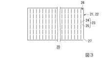
図3に示されるように、シート体20は、例えば、2枚の矩形のポリエチレン製のシート21,22の周囲が溶着されて袋状に形成されている。シート体20は、一枚のポリエチレン製のシートを折り曲げて周囲の三辺を溶着して形成されてもよいし、チューブ状のシートを潰した状態で両側の二辺を溶着して形成されてもよい。シート体20は、例えば、厚さが0.2[mm]程度である。 As shown in FIG. 3, the
周囲が溶着された2枚のシート21,22は、短辺方向に平行に複数の線状の仕切り23が形成されている。仕切り23は、2枚のシート21,22が互いに溶着されて形成された線状の複数の溶着部24と、溶着されていない気道25とを備える。複数の溶着部24の間には、気道25が所定の間隔で配置されている。これにより、シート体20には、軸線が短辺方向に沿った多数のセル26が隣接して形成されている。 The two sheets 21 and 22 whose peripheries are welded have a plurality of
シート体20の2つの短辺の一端側には溶着されていない吸気口27が設けられている。吸気口27から気体を流入させると、例えば、セル26が略円柱状に膨張する。そして、膨張を終えたセル26の各気道25から気体が隣接するセル26に流入し、隣接するセル26も略円柱状に膨張する。全てのセル26が膨張すると、シート体20は、マット状に膨張する。シート体20の長手方向の長さは、例えば、地盤面Eの一辺の長さとなるように形成されている。 An
このような構成の膨張前のシート体20を吸気口27が端部として現れるように長手方向に沿って巻回する。シート体20の巻回方向は、短手方向に沿った方向でもよい。巻回方向は、シート体20の大きさや形状、施工場所の状態に応じて適宜決定され、吸気口27の位置も、それに応じて適宜決定される。そのため、吸気口27は、シート体20の長辺側の任意の位置に設けられていてもよい。 The
図4(1)に示されるように、作業者は、巻回されたシート体20を床下換気口3から、挿入する。次に、作業者は、図4(2)に示されるように、シート体20の吸気口27にホースHの一端を接続し、床下換気口3を通過させてホースHの他端を建物の外部に配置されたブロワBの送風口に接続する。そして、作業者は、ブロワBを稼働させてシート体20の内部に気体(空気)を充填して手前側のセル26から順次、円筒状に膨張させる。気体は、ボンベに充填された圧縮性のガスを用いて体20の内部に充填するようにしてもよいし、もしくは非圧縮性の液体をシート体20の内部に充填するようにしてもよい。 As shown in FIG. 4(1), the operator inserts the
隣接するセル26を順次膨張させ、巻回されたシート体20を膨張したセル26に押し上げさせて、地盤面Eに転がり始めさせる。即ち、作業者は、シート体20の内部に気体を充填してシート体20を膨張させると共に、シート体20を地盤面E上に転がしながら展開させて敷設する。
そして、膨張を終えたセル26の各気道25から気体を隣接するセル26に流入させ、全てのセル26を膨張させ、シート体20を、マット状に展開させる。このように、巻回されたシート体20に空気を充填することにより、シート体20が転回して自走しながら展開する。このように、巻回されたシート体20を気体により膨張させながら展開させることにより、地盤面Eに凹凸や起伏が存在してもシート体20がそれらを乗り越えて自走させることができる。 Then, gas is caused to flow into the
シート体20の長手方向の長さは、例えば、地盤面Eの略一辺の長さとなるように形成されている。作業者は、例えば、展開されたシート体20を床下空間Sの地盤面Eの全体に敷設する。作業者は、展開されたシート体20を少なくとも床下空間Sの周辺側、即ち建物の外部空間に露出している立上り部2aの内側に沿って地盤面Eに敷設する。 The length of the
この時、作業者は、展開されたシート体20の位置が所定位置からずれている場合、床下換気口3から棒等を用いて押し込んだり、手繰り寄せたりしてシート体20を所定位置に敷設する。マット状に展開されたシート体20は、剛性が生じているため、作業者による建物の外部からの位置調整が容易に行われる。 At this time, if the position of the unfolded
作業者は、シート体20の敷設後に吸気口27からホースHを外す。この時、吸気口27は、必ずしも塞がれなくてもよい。即ちシート体20は、吸気口27から空気が抜けてカーペット状になってもよい。地盤面Eに既存の防湿土間コンクリートや、防湿シートが存在する場合には、これらをそのまま防湿手段として用いて、シート体20の敷設を省略してもよい。 After laying the
シート体20の上には、建物の外部空間に接している立上り部2aの内側(床下空間S側の壁)に沿って断熱部材30が設置される。断熱部材30は、後述のように、袋体31の内部に断熱材38を充填および圧入して形成される。 A
図5に示されるように、袋体31は、チューブ状に形成されたポリエチレン製のシートの開口した両端を溶着して形成されている。袋体31は、2枚の帯状のシートの四辺を溶着してチューブ形成されてもよいし、1枚のシートを折り曲げて周囲の三辺を溶着して形成されてもよい。袋体31には、袋体31の内部に気体と後述の断熱材を充填および圧入するための開口部32が形成されている。 As shown in FIG. 5, the
開口部32には、断熱材を充填および圧入するためのホースH1が挿入される。開口部32は、ホースH1の断面積よりも大きく開口するように形成されている。開口部32は、床下換気口3の位置に対応する位置に設けられている。 A hose H1 for filling and press-fitting a heat insulating material is inserted into the
袋体31は、開口部32から内部に気体や断熱材が充填および圧入された場合、円柱状に膨張する。袋体31は、膨張時に例えば、直径が500~600[mm]程度の略円柱状となる。袋体31は、後述のように内部に断熱材が充填および圧入された状態で、立上り部2aの内側に沿って設置される。膨張前の袋体31は、帯状に潰れた状態となっている。袋体31の長手方向の長さは、例えば、地盤面Eの一辺の長さとなるように形成されている。一辺の長さは、複数の袋体31が長手方向に並べられた際に全長が地盤面Eの一辺の長さとなるように決定されていてもよい。 The
膨張前の袋体31の長手方向の一辺には、例えば、長手方向に沿ってガイド棒Cが粘着テープT等を用いて取り付けられる。ガイド棒Cは、例えば、開口部32が設けられた袋体31の一辺側に取り付けられる。作業者は、例えば、床下換気口3の高さに合わせるように袋体31を適宜畳んで、膨張前の袋体31を床下換気口3からガイド棒Cと共に床下空間S内に、例えば矢印方向に沿って挿入する。そして、作業者は、袋体31を床下空間Sの外周に沿うように配置する。 For example, a guide rod C is attached to one longitudinal side of the
図6に示されるように、この配置工程において、作業者は、ガイド棒Cを立上り部2aの内側に沿わせながら移動させ、袋体31を立上り部2aの内側に並置させる。この時、作業者は、適宜異なる方向の床下換気口3から棒等を用いてガイド棒Cを押し込んだり手繰り寄せたりして袋体31の位置を調整する。 As shown in FIG. 6, in this arrangement step, the operator moves the guide rod C along the inside of the rising
袋体31は、直交する立上り部2aの内側に連続的に配置される。袋体31は、一つまたは複数のものを配置してもよいし、小梁が存在する場合は小梁の位置で分割して複数のものを配置してもよい。 The
ガイド棒Cは、袋体31に取り付けられたまま床下空間Sの中に残置される。袋体31が配置された後、作業者は、床下換気口3から開口部32を介して袋体31の内部に送風装置(不図示)に接続されたホースH1を挿入する。その後、作業者は、送風装置を稼働させ、先ず空気のみを袋体31の内部に送風し、袋体31を膨張させる。 The guide rod C remains attached to the
この時、作業者は、ガイド棒Cを保持する等して袋体31が立上り部2aの内側から隔離しないように袋体31の位置を調整する。作業者は、棒の先に取り付けた360度の視界を撮像するカメラ等を用いて床下空間S内を撮影することで、袋体31が適正な位置に配置されているか否かを確認することもできる。 At this time, the operator adjusts the position of the
次に、作業者は、流動性を有する断熱材を袋体の内部に流入させ、袋体を膨張させながら袋体31の内部に断熱材を充填および圧入する。流動性を有する断熱材とは、例えば、空気等の気体と断熱材とが混合された混合気体である。ここで、断熱材は、例えば、ホースH1の内部を流動するような大きさの綿状繊維の小塊が用いられる。綿状繊維には、例えば、セルロースファイバー、ウッドファイバー、綿、羊毛、グラスウール、ロックウール等が用いられる。断熱材には、綿状繊維だけでなく、チップ状、ビーズ状の発泡樹脂等が用いられてもよい。 Next, the operator causes the fluid heat insulating material to flow into the inside of the bag, and fills and press-fits the heat insulating material into the inside of the
袋体31の内部に断熱材を充填する際において、気体に水分が混合する場合がある。従って、断熱材は結露や凍結を防止するために、吸湿性および防湿性を有するものが望ましい。断熱材に吸湿性および防湿性が少ないものが用いられる場合、断熱材にシリカゲルや珪藻土等の吸湿性および調湿性を有する材料を混在させてもよい。 When filling the inside of the
断熱材を充填する行程において、作業者は、ホースH1の先端を袋体31の内部の端部の領域にまで到達するように配置する。その後、作業者は、送風装置を稼働させ、ホースH1の先端から袋体31の内部に断熱材と気体との混合気体を送風して断熱材を袋体31の端部から充填および圧入しながらホースH1を引き抜く方向に移動する。これにより、袋体31の端部から断熱材を充填および圧入することができる。 In the process of filling the heat insulating material, the operator places the tip of the hose H1 so as to reach the inner end region of the
作業者は、断熱材を充填する際に、袋体31の開口部32は、完全に塞がずに隙間を空けて空気を排出させる。空気を排出させるために、袋体31には開口部32の他に、別途に空気の排出口が設けられていてもよい。排出口は、袋体31において開口部32の近傍に設けてもよいし、他の位置に設けられていてもよい。 When filling the bag with the heat insulating material, the operator does not completely close the
袋体31は、断熱材が充填および圧入されるに従って重量が増加する。断熱材の重量の増加と共に、袋体31の下部に位置する膨張したシート体20のうち、袋体31を載置している部分が潰れて空気が排出される。断熱材が充填および圧入された袋体31は、例えば、地盤面Eと床スラブ10の下面との間を塞ぐように突っ張って略円柱状に膨張する。袋体31は、例えば、地盤面Eと床スラブ10の下面との間に挟まれて必ずしも略円柱状に膨張しない場合がある。 The weight of the
作業者は、袋体31の内部に断熱材を充填し終わった後、開口部32からホースH1を引き抜き、開口部32に粘着テープ等を張り付けて塞ぐ。上記工程により、略円柱状の断熱部材30が立上り部2aの内側に形成される。断熱部材30は、弾力性を有するため、地盤面Eに段差が生じていたり、上方に梁等の部材が存在したりしていても形状が馴染む。そして、断熱部材30は、膨張する過程で地盤面Eと床スラブ10の下面に圧着するため、特に固定手段を設けなくてもずれが生じにくくなる。 After the operator finishes filling the inside of the
断熱部材30によれば、断熱部材30と床スラブ10との間に隙間があったり、経時変化により隙間が生じたりしても、隙間の間隔が狭い場合、隙間においては空気が対流しにくくなるため、断熱性の低下が抑制される。このようにして断熱部材30を配置することにより、外部の空気に接している立上り部2aと建物の外周壁との間の隙間からの外気の進入を防止し、建物の気密性を向上させることにより、建物の漏気による熱損失が低減される。断熱部材30は、シート体20の上に設置されるため、地盤面E等の突起等による損傷等から保護される。また、固定手段を設けないことにより、断熱部材30の袋体31に破損が生じにくくなり、内部に充填された断熱材が床下空間Sに吹き出す可能性が低減される。 According to the
図7に示されるように、直交する二辺の立上り部2aの内側に配置された2つの袋体31に順次、断熱材が充填および圧入され、断熱部材30が形成される。この時、後に断熱材が充填および圧入される袋体31は、先に断熱材が充填された方の袋体31の状態にあわせて膨張する。既存の建物の形状によっては、断熱部材30は、床下空間Sの外周辺に沿って完全に連続していない場合や、隙間の生じる場合もある。 As shown in FIG. 7, a heat insulating material is sequentially filled and press-fitted into two
次に、作業者は、床下換気口3に床下空間Sの空気を排出するための換気装置40を設置する。換気装置40は、例えば、建物の外部から床下換気口3に設置される。換気装置40は、例えば、床下換気口3の開口の大きさにあわせて形成されている。換気装置40は、例えば、床下空間Sの空気を建物の外部に強制排気するファン41を備える。床下換気口3は、例えば、立上り部2aや小梁で区切られた1つの単位の床下空間Sに対して少なくとも1つ設置される。 Next, the worker installs a
換気装置40は、例えば、洗面所やトイレ等の非採暖室の下方に設置された床下換気口3に設置されることが好ましい。また、換気装置40は、稼働中の運転音が気にならない場所に設けられることが好ましい。また、換気装置40は、既存の電源(給湯器用の電源等)の近くに設けられることが好ましい。 The
換気装置40は、全ての床下換気口3に設置する必要はなく、換気装置40が設置されない他の床下換気口3には、外部から蓋45が設置されて開口が塞がれる。作業者は、蓋45の気密性を確保するために、例えば、居室内の床下点検口から床下空間Sに入り、蓋45の裏側から発泡樹脂等を用いて床下換気口3を塞いでもよい。また、作業者は、換気装置40もしくは蓋45の周辺の気密性を確保するために、換気装置40もしくは蓋45と床下換気口3との間の隙間に発泡樹脂等を充填してもよい。また、これらの作業は、床下点検口から床下空間Sに入るのが困難な場合は、建物の外部から行われてもよい。 The
蓋45の設置後、換気装置40を稼働させる。換気装置40と床下空間Sとの間が断熱部材30で密閉されている場合、断熱部材30を変形させて気道を確保してもよいし、床スラブ10と断熱部材30との間にパイプなどを挟んで気道を確保してもよい。また、断熱部材30の施工時に床下換気口3の位置で断熱部材30が分割されるように袋体31を設置してもよい。 After installing the
換気装置40を稼働して床下空間Sの空気を建物の外部に排気すると、床下空間Sの気圧が低下すると共に、床スラブ10の隙間から建物の居室内の空気が床下空間Sに供給される。そうすると建物の居室内の気圧は、外部の気圧に比して低下するので、建物の換気口や隙間から外部の空気が居室内に供給される。このようにして換気装置40が稼働することにより、建物内の空気の換気が行われる。 When the
また、換気装置40の稼働により、建物内の空気を換気することの他に、居室内の空調された空気を床下空間に導入して床下の空気の温度を居室内の空気の温度に近づけることができる。 Furthermore, by operating the
即ち、換気装置40が稼働することにより、例えば、冬場においては床下空間Sに空調された居室内の空気が導入され、床下空間S内の空気が暖められる。床下空間S内の空気は、周囲が断熱部材30により断熱されているため、冷えにくくなる。これにより、床下空間S内の温度が上昇し、床スラブ10に床下空間Sの空気の熱が伝導して居室内の床面の温度が断熱部材30や換気装置40を設置していない状態に比して上昇し、床面を快適な温度に保つことができる。 That is, by operating the
特に、上述のように洗面所やトイレ等の非採暖室の下部の床下換気口3に換気装置40が設置されるため、洗面所やトイレの床面の温度が快適に保たれる。また、換気装置40により居室内で空調された空気を床下空間Sに導入するため、湿気が床下空間Sに溜まることで発生する余剰な水分により床下空間が高湿度環境に長時間保持されることが防止される。上述したように、シート体20、断熱部材30、および換気装置40を設置する工程により、既存の建物の基礎の床下空間Sに断熱構造が施工される。 In particular, since the
上述したように、床下空間の断熱方法によれば、建物の外部から布基礎2に設けられた床下換気口3から断熱部材30を床下空間Sに設置するため、居室内に影響を与えずに床下空間の断熱の施工を行うことができる。即ち、床下空間の断熱方法によれば、建物の居住者に負担を与えず、居室内を汚すことが無く、居室内を養生する必要が無く、居住者が不在でも施工することが可能となる。また、断熱部材30は、袋体31の内部に断熱材が充填されているため、断熱材を入れ替える施工を行う際に回収が容易となる。 As described above, according to the underfloor space insulation method, the
本発明の技術範囲は、上述した各実施形態に限定されるものではなく、本発明の趣旨を逸脱しない範囲において、上述した実施形態に種々の変更を加えたものを含む。例えば、床下空間の断熱方法に用いられる断熱材には、シロアリ等の害虫を駆除するための防虫剤を混入させてもよい。また、夏場に換気装置40のファン41を逆回転させることにより、床下空間Sの地盤面Eの地熱により冷やされた空気を居室内に導入するようにしてもよい。また、上記床下空間の断熱方法は、既存の建物に施工する場合を例示したが新築の建物に適用してもよい。 The technical scope of the present invention is not limited to the embodiments described above, and includes various modifications to the embodiments described above without departing from the spirit of the invention. For example, an insect repellent for exterminating pests such as termites may be mixed into the heat insulating material used in the method of insulating the underfloor space. Moreover, by rotating the
1…基礎、2…布基礎、2a…立上り部、2b…フーチング部、3…床下換気口、3a…格子、10…床スラブ、20…シート体、21、22…シート、24…溶着部、25…気道、26…セル、27…吸気口、30…断熱部材、31…袋体、32…開口部、38…断熱材、40…換気装置、41…ファン、45…蓋、B…ブロワ、C…ガイド棒、E…地盤面、H、H1…ホース、S…床下空間、T…粘着テープ1... Foundation, 2... Fabric foundation, 2a... Rising part, 2b... Footing part, 3... Underfloor ventilation opening, 3a... Grid, 10... Floor slab, 20... Sheet body, 21, 22... Sheet, 24... Welded part, 25...Airway, 26...Cell, 27...Intake port, 30...Insulating member, 31...Bag, 32...Opening, 38...Insulating material, 40...Ventilator, 41...Fan, 45...Lid, B...Blower, C...Guide rod, E...Ground surface, H, H1...Hose, S...Underfloor space, T...Adhesive tape
Claims (11)
Translated fromJapanese前記袋体の一辺に取り付けられたガイド棒と、
を備える断熱部材により構成され、
前記袋体および前記ガイド棒は、床下空間において前記床下空間の外周に沿った基礎の立上り部に並置される、
床下空間の断熱構造。A tubular bag expanded into a columnar shape with insulation filled inside;
a guide rod attached to one side of the bag;
Consisting of a heat insulating member,
The bag body and the guide rod are juxtaposed in the underfloor space at a rising portion of a foundation along the outer periphery of the underfloor space.
Insulation structure for underfloor space.
請求項1に記載の床下空間の断熱構造。The guide rod is attached to one side of the bag along the longitudinal direction of the bag.
The insulation structure for an underfloor space according to claim 1.
前記シート体は、マット状に膨張した状態で前記床下空間の地盤面に敷設され、
前記断熱部材は、前記シート体に載置される、
請求項2に記載の床下空間の断熱構造。A moisture-proof sheet body that is formed into a bag shape and can be changed into a rolled state without being filled with gas inside, and a state where the inside is filled with gas and expanded into a mat shape. further comprising;
The sheet body is laid on the ground surface of the underfloor space in an expanded mat-like state,
The heat insulating member is placed on the sheet body,
The insulation structure for an underfloor space according to claim 2.
前記袋体を前記床下空間の外周に沿うように配置する配置工程と、
前記床下換気口から前記袋体の内部に流動性を有する断熱材を充填して柱状の前記断熱部材を形成する充填工程と、を備える、
請求項3に記載の床下空間の断熱構造の製造方法。an insertion step of inserting the bag, which expands into a columnar shape when filled with fluid, into the underfloor space from an underfloor ventilation opening provided in a rising portion of the foundation in a state before expansion;
arranging the bag along the outer periphery of the underfloor space;
a filling step of filling the interior of the bag with a fluid heat insulating material from the underfloor ventilation opening to form the columnar heat insulating member;
The method for manufacturing a heat insulating structure for an underfloor space according to claim 3.
請求項4に記載の床下空間の断熱構造の製造方法。In the insertion step, after attaching the guide rod to the uninflated bag, inserting the bag together with the guide rod from the underfloor ventilation opening.
The method for manufacturing a heat insulating structure for an underfloor space according to claim 4.
請求項5に記載の床下空間の断熱構造の製造方法。In the arrangement step, the guide rod is moved along the inside of the rising portion, and the bag body is juxtaposed inside the rising portion.
The method for manufacturing a heat insulating structure for an underfloor space according to claim 5.
請求項4から6のうちいずれか1項に記載の床下空間の断熱構造の製造方法。In the filling step, a gas mixture containing a gas and a heat insulating material is caused to flow into the inside of the bag, and the heat insulating material is filled into the inside of the bag while expanding the bag.
The method for manufacturing a heat insulating structure for an underfloor space according to any one of claims 4 to 6.
請求項4から7のうちいずれか1項に記載の床下空間の断熱構造の製造方法。In the filling step, a hose connected to a blower is inserted into the bag, and the tip of the hose is placed in an end region inside the bag, and then the blower is operated and the hose is blowing a mixture of the heat insulating material and gas into the inside of the bag to fill the heat insulating material while moving the hose in a direction to pull out the hose;
The method for manufacturing a heat insulating structure for an underfloor space according to any one of claims 4 to 7.
前記敷設工程は、前記床下換気口から膨張前の巻回された前記シート体を挿入した後、前記シート体の内部に気体を充填して前記シート体を膨張させると共に、前記シート体を前記床下空間の地盤面上に転がしながら展開させて敷設する、
請求項4から8のうちいずれか1項に記載の床下空間の断熱構造の製造方法。Before the insertion step, the method further comprises a laying step of laying the moisture-proof sheet body, which is expanded into a mat shape by filling with gas, on the ground surface of the underfloor space,
In the laying step, after inserting the uninflated rolled sheet body from the underfloor ventilation hole, gas is filled inside the sheet body to inflate the sheet body, and the sheet body is placed under the floor. It is laid out by rolling it on the ground surface of the space.
The method for manufacturing a heat insulating structure for an underfloor space according to any one of claims 4 to 8.
請求項4から9のうちいずれか1項に記載の床下空間の断熱構造の製造方法。After the filling step, an installation step is performed in which a ventilation device for discharging air from the underfloor space is installed in the underfloor ventilation hole, and another underfloor ventilation hole provided in the foundation that communicates with the outside is closed with a lid. Further prepare,
The method for manufacturing a heat insulating structure for an underfloor space according to any one of claims 4 to 9.
請求項10に記載の床下空間の断熱構造の製造方法。After the installation step, the method further includes a ventilation step of operating the ventilation device to exhaust the air inside the underfloor space to the outside and introduce indoor air into the underfloor space.
The method for manufacturing a heat insulating structure for an underfloor space according to claim 10.
Priority Applications (1)
| Application Number | Priority Date | Filing Date | Title |
|---|---|---|---|
| JP2022196207AJP7369850B2 (en) | 2018-08-31 | 2022-12-08 | Underfloor space insulation structure and manufacturing method for underfloor space insulation structure |
Applications Claiming Priority (2)
| Application Number | Priority Date | Filing Date | Title |
|---|---|---|---|
| JP2018163102AJP7193955B2 (en) | 2018-08-31 | 2018-08-31 | Heat insulation method for underfloor space and heat insulation structure for underfloor space |
| JP2022196207AJP7369850B2 (en) | 2018-08-31 | 2022-12-08 | Underfloor space insulation structure and manufacturing method for underfloor space insulation structure |
Related Parent Applications (1)
| Application Number | Title | Priority Date | Filing Date |
|---|---|---|---|
| JP2018163102ADivisionJP7193955B2 (en) | 2018-08-31 | 2018-08-31 | Heat insulation method for underfloor space and heat insulation structure for underfloor space |
Publications (2)
| Publication Number | Publication Date |
|---|---|
| JP2023022299A JP2023022299A (en) | 2023-02-14 |
| JP7369850B2true JP7369850B2 (en) | 2023-10-26 |
Family
ID=69667402
Family Applications (2)
| Application Number | Title | Priority Date | Filing Date |
|---|---|---|---|
| JP2018163102AActiveJP7193955B2 (en) | 2018-08-31 | 2018-08-31 | Heat insulation method for underfloor space and heat insulation structure for underfloor space |
| JP2022196207AActiveJP7369850B2 (en) | 2018-08-31 | 2022-12-08 | Underfloor space insulation structure and manufacturing method for underfloor space insulation structure |
Family Applications Before (1)
| Application Number | Title | Priority Date | Filing Date |
|---|---|---|---|
| JP2018163102AActiveJP7193955B2 (en) | 2018-08-31 | 2018-08-31 | Heat insulation method for underfloor space and heat insulation structure for underfloor space |
Country Status (1)
| Country | Link |
|---|---|
| JP (2) | JP7193955B2 (en) |
Citations (5)
| Publication number | Priority date | Publication date | Assignee | Title |
|---|---|---|---|---|
| JP2002250088A (en) | 2001-02-26 | 2002-09-06 | Sunrise Kogyo Kk | Thermal insulating building material and thermal insulating construction method for house using the same |
| JP2009046801A (en) | 2007-08-13 | 2009-03-05 | Sekisui Chem Co Ltd | Building basic insulation structure and construction method |
| JP2015083760A (en) | 2013-10-25 | 2015-04-30 | 旭化成ホームズ株式会社 | Method for ventilating inside building foundation and ventilation structure |
| JP2015121033A (en) | 2013-12-24 | 2015-07-02 | 大和ハウス工業株式会社 | Building ventilation structure |
| US20160052696A1 (en) | 2014-08-22 | 2016-02-25 | Owens Corning Intellectual Capital, Llc | General purpose insulation bag |
Family Cites Families (3)
| Publication number | Priority date | Publication date | Assignee | Title |
|---|---|---|---|---|
| JPS54117114A (en)* | 1978-03-01 | 1979-09-11 | Paramount Glass Mfg Co Ltd | Heat insulating execution method to under surface of ceiling |
| JPS55129533A (en)* | 1979-03-30 | 1980-10-07 | Koodo Kk | Method of filling heat and sound insulating material in building |
| JPS5865842A (en)* | 1981-10-16 | 1983-04-19 | 株式会社大仙 | Double coated curtain apparatus of building |
- 2018
- 2018-08-31JPJP2018163102Apatent/JP7193955B2/enactiveActive
- 2022
- 2022-12-08JPJP2022196207Apatent/JP7369850B2/enactiveActive
Patent Citations (5)
| Publication number | Priority date | Publication date | Assignee | Title |
|---|---|---|---|---|
| JP2002250088A (en) | 2001-02-26 | 2002-09-06 | Sunrise Kogyo Kk | Thermal insulating building material and thermal insulating construction method for house using the same |
| JP2009046801A (en) | 2007-08-13 | 2009-03-05 | Sekisui Chem Co Ltd | Building basic insulation structure and construction method |
| JP2015083760A (en) | 2013-10-25 | 2015-04-30 | 旭化成ホームズ株式会社 | Method for ventilating inside building foundation and ventilation structure |
| JP2015121033A (en) | 2013-12-24 | 2015-07-02 | 大和ハウス工業株式会社 | Building ventilation structure |
| US20160052696A1 (en) | 2014-08-22 | 2016-02-25 | Owens Corning Intellectual Capital, Llc | General purpose insulation bag |
Also Published As
| Publication number | Publication date |
|---|---|
| JP2020033809A (en) | 2020-03-05 |
| JP2023022299A (en) | 2023-02-14 |
| JP7193955B2 (en) | 2022-12-21 |
Similar Documents
| Publication | Publication Date | Title |
|---|---|---|
| KR101672353B1 (en) | Assembling air house | |
| US4696138A (en) | Insulation configurations and method of increasing insulation efficiency | |
| JP2001116292A (en) | Air-conditioning system utilizing geothermy | |
| JP2008502827A (en) | Prefabricated shelter | |
| JP7369850B2 (en) | Underfloor space insulation structure and manufacturing method for underfloor space insulation structure | |
| US20090019802A1 (en) | Adjustable insulation containment apparatus | |
| JP2001289518A (en) | Outside-air inlet device for building | |
| JP4223467B2 (en) | Temperature control structure and temperature control method for buildings | |
| US20070084139A1 (en) | Exterior wall assembly | |
| JP2009084936A (en) | Thermal insulation dwelling house and ventilation system | |
| JP2007191935A (en) | Wall structure having moisture permeability and high heat insulation properties, and method of constructing wall | |
| JP3122022B2 (en) | Air circulation building | |
| CN105220906B (en) | A kind of packaged type tent hotel based on geothermal heat pump air-conditioning system | |
| JP5805810B2 (en) | Building ventilation structure | |
| JP2005042958A (en) | Heating system | |
| JP4118976B2 (en) | Wooden building | |
| JP5866532B2 (en) | Air purification type building and air purification method for building | |
| JPS6022281Y2 (en) | Underfloor heat storage device | |
| US20220316645A1 (en) | Insulated portable spa and processes for insulating | |
| JP3029335U (en) | Wooden house with central heating and ventilation system utilizing underfloor space | |
| JP2004271122A (en) | Floor heating apparatus and thermal storage body used for the same and its manufacturing method | |
| JP2873564B2 (en) | Building | |
| JP3075469U (en) | Wooden house adopting centralized heating and ventilation system utilizing underfloor space | |
| JPH07293909A (en) | Hot air floor heating device and its working method | |
| JP2003056068A (en) | Building unit and building and method for executing unit building |
Legal Events
| Date | Code | Title | Description |
|---|---|---|---|
| A621 | Written request for application examination | Free format text:JAPANESE INTERMEDIATE CODE: A621 Effective date:20221208 | |
| TRDD | Decision of grant or rejection written | ||
| A01 | Written decision to grant a patent or to grant a registration (utility model) | Free format text:JAPANESE INTERMEDIATE CODE: A01 Effective date:20231003 | |
| A61 | First payment of annual fees (during grant procedure) | Free format text:JAPANESE INTERMEDIATE CODE: A61 Effective date:20231016 | |
| R150 | Certificate of patent or registration of utility model | Ref document number:7369850 Country of ref document:JP Free format text:JAPANESE INTERMEDIATE CODE: R150 |