JP7369792B2 - tracheostomy dilator - Google Patents
tracheostomy dilatorDownload PDFInfo
- Publication number
- JP7369792B2 JP7369792B2JP2021568262AJP2021568262AJP7369792B2JP 7369792 B2JP7369792 B2JP 7369792B2JP 2021568262 AJP2021568262 AJP 2021568262AJP 2021568262 AJP2021568262 AJP 2021568262AJP 7369792 B2JP7369792 B2JP 7369792B2
- Authority
- JP
- Japan
- Prior art keywords
- proximal
- tracheostomy
- handle portion
- distal
- tracheostomy dilator
- Prior art date
- Legal status (The legal status is an assumption and is not a legal conclusion. Google has not performed a legal analysis and makes no representation as to the accuracy of the status listed.)
- Active
Links
- 230000007423decreaseEffects0.000claimsdescription2
- 238000003780insertionMethods0.000description24
- 230000037431insertionEffects0.000description24
- 210000003437tracheaAnatomy0.000description8
- 239000011248coating agentSubstances0.000description5
- 238000000576coating methodMethods0.000description5
- 230000003247decreasing effectEffects0.000description5
- 238000004049embossingMethods0.000description5
- 235000015110jelliesNutrition0.000description5
- 239000008274jellySubstances0.000description5
- 230000001050lubricating effectEffects0.000description5
- 238000012986modificationMethods0.000description2
- 230000004048modificationEffects0.000description2
- 230000002093peripheral effectEffects0.000description2
- 229940124630bronchodilatorDrugs0.000description1
Images


Classifications
- A—HUMAN NECESSITIES
- A61—MEDICAL OR VETERINARY SCIENCE; HYGIENE
- A61M—DEVICES FOR INTRODUCING MEDIA INTO, OR ONTO, THE BODY; DEVICES FOR TRANSDUCING BODY MEDIA OR FOR TAKING MEDIA FROM THE BODY; DEVICES FOR PRODUCING OR ENDING SLEEP OR STUPOR
- A61M16/00—Devices for influencing the respiratory system of patients by gas treatment, e.g. ventilators; Tracheal tubes
- A61M16/04—Tracheal tubes
- A61M16/0465—Tracheostomy tubes; Devices for performing a tracheostomy; Accessories therefor, e.g. masks, filters
- A61M16/0472—Devices for performing a tracheostomy
- A—HUMAN NECESSITIES
- A61—MEDICAL OR VETERINARY SCIENCE; HYGIENE
- A61M—DEVICES FOR INTRODUCING MEDIA INTO, OR ONTO, THE BODY; DEVICES FOR TRANSDUCING BODY MEDIA OR FOR TAKING MEDIA FROM THE BODY; DEVICES FOR PRODUCING OR ENDING SLEEP OR STUPOR
- A61M16/00—Devices for influencing the respiratory system of patients by gas treatment, e.g. ventilators; Tracheal tubes
- A61M16/04—Tracheal tubes
- A61M16/0475—Tracheal tubes having openings in the tube
Landscapes
- Health & Medical Sciences (AREA)
- Pulmonology (AREA)
- Emergency Medicine (AREA)
- Engineering & Computer Science (AREA)
- Anesthesiology (AREA)
- Biomedical Technology (AREA)
- Heart & Thoracic Surgery (AREA)
- Hematology (AREA)
- Life Sciences & Earth Sciences (AREA)
- Animal Behavior & Ethology (AREA)
- General Health & Medical Sciences (AREA)
- Public Health (AREA)
- Veterinary Medicine (AREA)
- Surgical Instruments (AREA)
- Media Introduction/Drainage Providing Device (AREA)
Description
Translated fromJapanese (優先権)
本特許出願は、2019年5月15日に出願された米国仮特許出願第62/848,310号に対する優先権を主張するものであり、その開示内容全体は、引用により本明細書に組み込まれる。(priority)
This patent application claims priority to U.S. Provisional Patent Application No. 62/848,310, filed May 15, 2019, the entire disclosure of which is incorporated herein by reference. .
(技術分野)
本開示は、一般に、拡張器に関し、より詳細には、ガイドワイヤの挟み込みを低減又は防止するように構成された経皮的気管切開用拡張器に関する。(Technical field)
TECHNICAL FIELD This disclosure relates generally to dilators and, more particularly, to percutaneous tracheostomy dilators configured to reduce or prevent guidewire entrapment.
経皮的気管切開術は、中空の針を皮膚に通して気管に挿入し、開口部内でガイドワイヤを針に沿って挿入することによって形成することができる。次いで、針を引き抜き、ガイドワイヤを介して気管切開用拡張器を通して、気管切開チューブを挿入するための開口部を拡張する。本発明は、従来技術の気管切開拡張器に関する1又は2以上の問題点を解決する。 A percutaneous tracheostomy can be created by inserting a hollow needle through the skin into the trachea and inserting a guidewire along the needle within the opening. The needle is then withdrawn and passed through the tracheostomy dilator over the guide wire to dilate the opening for insertion of the tracheostomy tube. The present invention solves one or more problems associated with prior art tracheostomy dilators.
本発明の一態様は、遠位部分、ハンドル部分、内腔、及び近位部分を含む気管切開用拡張器に向けられる。遠位部分は、遠位開口部まで延びる曲線を有し、気管切開部を拡張するように構成することができる。ハンドル部分は、遠位部分の近位にあり、ユーザによって把持されるように構成することができる。内腔は、ガイドワイヤを受け入れるように構成することができる。近位部分は、ハンドル部分の近位にあり、内腔と連通する近位開口部を有することができる。近位部分は、ハンドル部分の長手方向軸から少なくとも30度の角度でガイドワイヤを偏位させるように構成することができる。 One aspect of the invention is directed to a tracheostomy dilator that includes a distal portion, a handle portion, a lumen, and a proximal portion. The distal portion may have a curve extending to the distal opening and may be configured to dilate the tracheostomy. A handle portion is proximal to the distal portion and can be configured to be grasped by a user. The lumen can be configured to receive a guidewire. The proximal portion is proximal to the handle portion and can have a proximal opening in communication with the lumen. The proximal portion can be configured to offset the guidewire at an angle of at least 30 degrees from the longitudinal axis of the handle portion.
幾つかの実施形態では、角度は、ハンドル部分の長手方向軸から少なくとも45度とすることができる。幾つかの実施形態では、ハンドル部分は、実質的に直線状とすることができる。幾つかの実施形態では、ハンドル部分は、テクスチャ化することができる。幾つかの実施形態では、ハンドル部分は、テクスチャ化されたスリーブを含むことができる。幾つかの実施形態では、遠位部分は、遠位部分の長さに沿って減少する壁厚を有することができる。幾つかの実施形態では、気管切開拡張器は更に、遠位部分上に気管切開拡張器のサイズの指標を含むことができる。幾つかの実施形態では、近位開口部は、長手方向軸からの角度にて配置することができる。幾つかの実施形態では、近位部分は、長手方向軸から角度まで延びる屈曲部を有することができる。幾つかの実施形態では、近位部分は、ハンドル部分の長手方向軸と長手方向に位置合わせすることができる。幾つかの実施形態では、近位部分は、近位開口部にて周壁にベベルを有することができ、周壁が下側部分よりも上側部分で近位方向に更に延びるようになる。幾つかの実施形態では、ベベルは湾曲することができる。幾つかの実施形態では、近位部分は、近位開口部の遠位で近位開口部と連通する孔を有することができ、孔は、ガイドワイヤを受け入れるように構成されている。幾つかの実施形態では、近位部分は、近位開口部と孔とを接続するスロットを有することができ、スロットは、近位開口部及び孔よりも小さい幅を有することができる。幾つかの実施形態では、近位部分は、ハンドル部分に対して長手方向軸の周りに回転可能とすることができる。幾つかの実施形態では、近位部分は、ハンドル部分から取り外し可能とすることができる。幾つかの実施形態では、近位部分は、近位部分をハンドル部分に着脱可能に固定するためにハンドル部分内に受け入れられた管状セグメントを有するインサートを含むことができる。 In some embodiments, the angle can be at least 45 degrees from the longitudinal axis of the handle portion. In some embodiments, the handle portion can be substantially straight. In some embodiments, the handle portion can be textured. In some embodiments, the handle portion can include a textured sleeve. In some embodiments, the distal portion can have a wall thickness that decreases along the length of the distal portion. In some embodiments, the tracheostomy dilator can further include tracheostomy dilator size indicia on the distal portion. In some embodiments, the proximal opening can be positioned at an angle from the longitudinal axis. In some embodiments, the proximal portion can have a bend extending at an angle from the longitudinal axis. In some embodiments, the proximal portion can be longitudinally aligned with the longitudinal axis of the handle portion. In some embodiments, the proximal portion can have a bevel in the circumferential wall at the proximal opening such that the circumferential wall extends further in the proximal direction at the upper portion than at the lower portion. In some embodiments, the bevel can be curved. In some embodiments, the proximal portion can have a hole in communication with the proximal opening distal to the proximal opening, the hole being configured to receive a guidewire. In some embodiments, the proximal portion can have a slot connecting the proximal opening and the hole, and the slot can have a width that is less than the proximal opening and the hole. In some embodiments, the proximal portion can be rotatable about a longitudinal axis relative to the handle portion. In some embodiments, the proximal portion can be removable from the handle portion. In some embodiments, the proximal portion can include an insert having a tubular segment received within the handle portion to removably secure the proximal portion to the handle portion.
本発明の別の態様は、遠位部分、ハンドル部分、内腔、及び近位部分を含む気管切開拡張器に向けられる。遠位部分は、遠位開口部まで延びる曲線を有し、気管切開部を拡張するように構成することができる。ハンドル部分は、遠位部分の近位にあり、ユーザによって把持されるように構成することができる。内腔は、ガイドワイヤを受け入れるように構成することができる。近位部分は、ハンドル部分の近位にあり、内腔と連通する近位開口部を有することができる。近位部分は、ベベルを有することができる。 Another aspect of the invention is directed to a tracheostomy dilator that includes a distal portion, a handle portion, a lumen, and a proximal portion. The distal portion may have a curve extending to the distal opening and may be configured to dilate the tracheostomy. A handle portion is proximal to the distal portion and can be configured to be grasped by a user. The lumen can be configured to receive a guidewire. The proximal portion is proximal to the handle portion and can have a proximal opening in communication with the lumen. The proximal portion can have a bevel.
幾つかの実施形態では、ベベルは、近位開口部にて円周壁にあることができ、円周壁が下側部分よりも上側部分で近位方向に更に延びるようになっている。幾つかの実施形態では、近位部分は、ハンドル部分の長手方向軸と長手方向に位置合わせすることができる。幾つかの実施形態では、近位部分は、近位開口部の遠位で且つ近位開口部と連通する孔を更に含むことができ、孔は、ガイドワイヤを受け入れるように構成されている。幾つかの実施形態では、近位部分は、近位開口部と孔とを接続するスロットを含むことができ、スロットは、近位開口部及び孔よりも小さい幅を有することができる。 In some embodiments, the bevel can be on the circumferential wall at the proximal opening, such that the circumferential wall extends further proximally in the upper portion than in the lower portion. In some embodiments, the proximal portion can be longitudinally aligned with the longitudinal axis of the handle portion. In some embodiments, the proximal portion can further include a hole distal to and in communication with the proximal opening, the hole configured to receive a guidewire. In some embodiments, the proximal portion can include a slot connecting the proximal opening and the hole, and the slot can have a width that is less than the proximal opening and the hole.
本発明が容易に理解されるようにするために、本発明の態様は、添付図面において例示として示されている。 In order that the invention may be easily understood, aspects of the invention are shown by way of example in the accompanying drawings.
図面及び以下の詳細な説明において、同一又は類似の要素を指すのに同じ参照番号を使用する場合がある。 The same reference numbers may be used in the drawings and the following detailed description to refer to the same or similar elements.
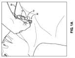
図1A~1Bは、ガイドワイヤ20を介して気管切開部30に挿入された気管切開部拡張器10を示している。気管切開拡張器10の遠位端(図示せず)は、気管切開チューブ(図示せず)の挿入のために気管切開部30を拡張するように構成される。気管切開拡張器10がガイドワイヤ20を介して気管切開部30に挿入されるときに、気管切開拡張器10のハンドル部分12は、ユーザによって把持される。気管切開拡張器10がガイドワイヤ20上を進むと、ガイドワイヤ20は、ハンドル部分12の近位端部にて近位開口部14を通って出る。近位開口部14は、ハンドル部分12の長手方向軸に沿って配置されており、ユーザが気管切開拡張器10を気管切開部30に押し込むときに、ユーザの手のひらが近位開口部14を覆う及び/又はハンドル部分12の近位端部にガイドワイヤ20を挟み込む傾向があるようになる。このガイドワイヤ20の偶発的挟み込みは、気管切開用拡張器10を進めるときに更に気管内へのガイドワイヤ20の望ましくない押し込みをすること、及び/又は気管切開用拡張器10を取り外すときにガイドワイヤ20を気管から引き抜くことを含む、多くの複雑な問題を引き起こす可能性がある。本開示は、これらの問題のうちの1又は2以上、及び/又は気管切開用拡張器及び/又は拡張器全般に関連する他の問題を軽減及び/又は克服することを目的とする。 1A-1B
本開示は、ユーザの手からの干渉を低減又は防止するために、ハンドル部分の長手方向軸から離れてガイドワイヤをシールド及び/又は偏位するように構成された気管切開用拡張器に向けられている。幾つかの実施形態では、気管切開用拡張器は、ガイドワイヤをハンドル部分の長手方向軸から少なくとも30度偏位させることができ、ハンドル部分は、把持を容易にするために実質的に直線状である。幾つかの実施形態では、気管支拡張器は、ガイドワイヤをハンドル部分の長手方向軸から少なくとも45度偏位させることができる。ガイドワイヤの偏位は、ハンドル部分と近位開口部との間の気管切開用拡張器の近位部分での屈曲部によって引き起こすことができる。屈曲部は、鋭いベベル及び/又は湾曲部を含むことができる。幾つかの実施形態では、近位部分は、近位開口部の面にて面取りすることができ、これにより、近位部分の周壁が、下部よりも上部にて近位方向に更に延び、上方から把持したときにガイドワイヤを効果的にシールドする。幾つかの実施形態では、近位部分は、追加的又は代替的に、底部の底面を貫通して近位開口部と連通する孔を含むことができる。この孔は、狭いスロット付きの近位開口部に接続することができ、ユーザがハンドルを上方から把持したときに挟み込みの可能性を低減又は防止するために、ガイドワイヤが孔に受け入ることができるようになる。幾つかの実施形態では、近位部分は、ハンドル部分の長手方向軸の周りで回転可能及び/又はハンドル部分から着脱可能とすることができる。このように、気管切開拡張器の様々な実施形態は、気管切開拡張器の近位端部に対するユーザの手によるガイドワイヤの挟み込みを低減又は防止するために、ガイドワイヤをシールド及び/又は偏位することができる。 The present disclosure is directed to a tracheostomy dilator configured to shield and/or deflect a guidewire away from a longitudinal axis of a handle portion to reduce or prevent interference from a user's hand. ing. In some embodiments, the tracheostomy dilator can offset the guidewire at least 30 degrees from the longitudinal axis of the handle portion, the handle portion being substantially straight to facilitate grasping. It is. In some embodiments, the bronchodilator can offset the guidewire at least 45 degrees from the longitudinal axis of the handle portion. Guidewire deflection can be caused by a bend in the proximal portion of the tracheostomy dilator between the handle portion and the proximal opening. The bends can include sharp bevels and/or curves. In some embodiments, the proximal portion can be chamfered at the plane of the proximal opening, such that the peripheral wall of the proximal portion extends further in the proximal direction at the top than at the bottom and extends upwardly. Effectively shields the guide wire when grasped from the ground. In some embodiments, the proximal portion may additionally or alternatively include a hole through the bottom surface of the base and communicating with the proximal opening. This hole can be connected to a narrow slotted proximal opening into which a guidewire can be received to reduce or prevent the possibility of entrapment when a user grasps the handle from above. become able to. In some embodiments, the proximal portion can be rotatable about the longitudinal axis of the handle portion and/or removable from the handle portion. As such, various embodiments of the tracheostomy dilator shield and/or deflect the guidewire to reduce or prevent pinching of the guidewire by a user's hand against the proximal end of the tracheostomy dilator. can do.
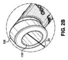
図2A~2Cは、気管切開拡張器100の第1の例示的な実施形態を示す。気管切開拡張器100は、遠位部分102、ハンドル部分104、近位部分106、及び貫通して延びる内腔を含むことができる。 2A-2C illustrate a first exemplary embodiment of a
遠位部分102は、ハンドル部分104から内腔の遠位開口部を有する遠位先端110まで延びる連続的曲線を含むことができる。連続的曲線は、気管切開拡張器100が挿入中に気管を通過し、遠位先端110が気管後壁をクリアすることを可能にする。遠位部分102は、挿入を容易にするために、連続的曲線に沿って遠位先端110までテーパーを付けることができる。例えば、遠位部分102は、遠位先端110への連続曲線に沿って徐々に減少する壁厚を介してテーパーを付けることができる。遠位部分102は、気管切開部への挿入の際の摩擦を低減し、潤滑ゼリーの必要性を排除するために親水性コーティングを有することができる。また、遠位部分102は、遠位部分102の断面サイズ及び深さの指標112を含むことができる。例えば、図2Cに示されているように、指標112は、直径(例えば、38フレンチ)と、気管切開部を拡張するための遠位部分102の挿入の適切な深さを示す少なくとも部分的に円周廻りの線と、を含むことができる。
ハンドル部分104は、実質的に直線状であり、遠位部分102と一体的に形成された細長い直線状シャフトを含むことができる。ハンドル部分104は、遠位部分102の近位にあって、ユーザによって把持されるように構成することができる。ハンドル部分104は、ユーザのグリップ及び操作性を向上させるためにテクスチャ化することができる。例えば、ハンドル部分104は、シャフト上にテクスチャ付きゴムスリーブ114を含むことができる。テクスチャ化された表面上のグリップは、ハンドル部分104及び/又はスリーブ114の長さに沿って、複数の隆起した単語及び/又はロゴ(LOGO)(例えば、製造者及び/又は販売者の)をエンボス加工することによって強化することができる。スリーブ114は、相対的な滑りを防止するために、シャフトの外面上の細長い凹部に受け入れることができる。
近位部分106は、ハンドル部分104の長手方向軸から少なくとも30~45度の角度でガイドワイヤ20を偏位させるように構成することができる。近位部分106は、ハンドル部分104及び/又は遠位部分102の細長い直線状シャフトに一体化することができる。近位部分106は、ハンドル部分104の長手方向軸から少なくとも30~45度の角度で近位部分106の近位開口部118の長手方向軸を配置するベベル116を含むことができる。偏位したガイドワイヤ20は、前進したときに気管切開拡張器100の近位開口部118から外に通過することができる。近位部分106は、外面と、ハンドル部分104の長手方向軸から少なくとも30~45度の角度で配置された長手方向軸を有する内腔とを備えて、円形断面を有することができる。近位部分106と近位開口部118との相対角度により、ユーザがハンドル部分104を把持するときに、指及び/又は手のひらによるガイドワイヤ20の挟み込みが低減又は防止される。
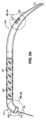
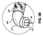
図3A~3Cは、気管切開拡張器200の第2の例示的な実施形態を示す。気管切開拡張器200は、遠位部分202、ハンドル部分204、近位部分206、及び貫通して延びる内腔を含むことができる。 3A-3C illustrate a second exemplary embodiment of a
遠位部分202は、ハンドル部分204から、内腔の遠位開口部を有する遠位先端210まで延びる連続的曲線を含むことができる。連続的曲線は、気管切開拡張器200が挿入中に気管を通過すること、及び遠位先端210が気管後壁をクリアすることを可能にすることができる。遠位部分202は、挿入を容易にするために、連続的曲線に沿って遠位先端210までテーパーを付けることができる。例えば、遠位部分202は、遠位先端210まで連続曲線に沿って徐々に減少する壁厚を介してテーパーを付けることができる。遠位部分202は、気管切開への挿入の際の摩擦を低減し、潤滑ゼリーの必要性を排除するために親水性コーティングを有することができる。また、遠位部分202は、遠位部分202の断面サイズ及び深さの指標212を含むことができる。例えば、図3Cに示されているように、指標212は、直径(例えば、38フレンチ)と、気管切開を拡張するための遠位部分202の挿入の適切な深さを示す少なくとも部分的に円周廻りの線と、を含むことができる。
ハンドル部分204は、実質的に直線であり、遠位部分202と一体的に形成された細長い直線状シャフトを含むことができる。ハンドル部分204は、遠位部分202の近位にあって、ユーザによって把持されるように構成することができる。ハンドル部分204は、ユーザのグリップ及び操作性を向上させるためにテクスチャ化することができる。例えば、ハンドル部分204は、シャフト上にテクスチャ付きゴムスリーブ214を含むことができる。テクスチャ化された表面上のグリップは、ハンドル部分204及び/又はスリーブ214の長さに沿って、複数の隆起した単語及び/又はロゴ(LOGO)(例えば、製造者及び/又は販売者の)をエンボス加工することによって強化することができる。スリーブ214は、相対的な滑りを防止するために、シャフトの外面上の細長い凹部に受け入れることができる。
近位部分206は、ハンドル部分204の長手方向軸から少なくとも30~45度の角度でガイドワイヤ20を偏位させるように構成することができる。近位部分206は、ハンドル部分204及び/又は遠位部分202の細長い直線状シャフトに一体化することができる。近位部分206は、ハンドル部分204の長手方向軸から少なくとも30~45度の角度で近位開口部218の長手方向軸を配置する曲線217を含むことができる。偏位したガイドワイヤ20は、前進したときに気管切開拡張器200の近位開口部218から外に通過することができる。近位部分206は、ハンドル部分204の長手方向軸から少なくとも30~45度の角度に湾曲する外面を有する円形断面を有することができる。近位部分206と近位開口部218の相対角度に起因して、ユーザがハンドル部分204を把持するときに、指及び/又は手のひらによるガイドワイヤ20の挟み込みが低減又は防止される。
図4A~4Cは、気管切開拡張器300の第3の例示的な実施形態を示す。気管切開拡張器300は、遠位部分302、ハンドル部分304、近位部分306、及び貫通して延びる内腔を含むことができる。 4A-4C illustrate a third exemplary embodiment of a
遠位部分302は、ハンドル部分304から、内腔の遠位開口部を有する遠位先端310まで延びる連続的曲線を含むことができる。連続的曲線は、気管切開拡張器300が挿入中に気管を通過すること、及び遠位先端310が気管後壁をクリアすることを可能にすることができる。遠位部分302は、挿入を容易にするために、連続的曲線に沿って遠位先端310までテーパーを付けることができる。例えば、遠位部分302は、遠位先端310まで連続曲線に沿って徐々に減少する壁厚を介してテーパーを付けることができる。遠位部分302は、気管切開への挿入の際の摩擦を低減し、潤滑ゼリーの必要性を排除するために、親水性コーティングを有することができる。また、遠位部分302は、遠位部分302の断面サイズ及び深さの指標312を含むことができる。例えば、図4Cに示されているように、指標312は、直径(例えば、38フレンチ)と、気管切開を拡張するための遠位部分302の挿入の適切な深さを示す少なくとも部分的に円周廻りの線と、を含むことができる。
ハンドル部分304は、実質的に直線であり、遠位部分302と一体的に形成された細長い直線状シャフトを含むことができる。ハンドル部分304は、遠位部分302の近位にあって、ユーザによって把持されるように構成することができる。ハンドル部分304は、ユーザのグリップ及び操作性を向上させるためにテクスチャ化することができる。例えば、ハンドル部分304は、シャフト上にテクスチャ付きゴムスリーブ314を含むことができる。テクスチャ化された表面上のグリップは、ハンドル部分304及び/又はスリーブ314の長さに沿って、複数の隆起した単語及び/又はロゴ(LOGO)(例えば、製造者及び/又は販売者の)をエンボス加工することによって強化することができる。スリーブ314は、相対的な滑りを防止するために、シャフトの外面上の細長い凹部に受け入れることができる。
近位部分306は、ハンドル部分304の長手方向軸から少なくとも30~45度の角度でガイドワイヤ20を偏位させるように構成することができる。近位部分306は、ハンドル部分304及び/又は遠位部分302の細長い直線状シャフトに一体化することができる。近位部分306は、内腔の近位開口部318を含むことができ、この内腔を介して、偏位したガイドワイヤ20は、前進したときに気管切開拡張器300から外に通過することができる。近位開口部318は、ベベル320を含むことができ、近位部分306の周壁が下側部分324よりも上側部分322にて近位方向に更に延びるようにし、上方から把持したときにガイドワイヤ20を効果的にシールドすることができる。近位部分306は、ハンドル部分304の長手方向軸と長手方向に位置合わせすることができ、ベベル320は、長手方向軸から約45度に配置することができる。下側部分324は、近位開口部318の遠位で且つ近位開口部318及び内腔と両方とも連通する、スロット326及び孔328を有することができる。スロット326は、近位開口部318及び/又は孔328よりも狭くすることができる。ガイドワイヤ20は、近位開口部318から孔328を通ってスロット326内に下方に偏位して、ハンドル部分304を上方から把持したときに挟み込みを低減又は防止することができる。
図5A~5Cは、気管切開拡張器400の第4の例示的な実施形態を示す。気管切開拡張器400は、遠位部分402、ハンドル部分404、近位部分406、及び貫通して延びる内腔を含むことができる。 5A-5C illustrate a fourth exemplary embodiment of a
遠位部分402は、ハンドル部分404から、内腔の遠位開口部を有する遠位先端410まで延びる連続的曲線を含むことができる。連続的曲線は、気管切開拡張器400が挿入中に気管を通過すること、及び遠位先端410が気管後壁をクリアすることを可能にすることができる。遠位部分402は、挿入を容易にするために、連続的曲線に沿って遠位先端410までテーパーを付けることができる。例えば、遠位部分402は、遠位先端410まで連続曲線に沿って徐々に減少する壁厚を介してテーパーを付けることができる。遠位部分402は、気管切開への挿入の際の摩擦を低減し、潤滑ゼリーの必要性を排除するために親水性コーティングを有することができる。また、遠位部分402は、遠位部分402の断面サイズ及び深さの指標412を含むことができる。例えば、図5Cに示されているように、指標412は、直径(例えば、38フレンチ)と、気管切開を拡張するための遠位部分402の挿入の適切な深さを示す少なくとも部分的に円周廻りの線と、を含むことができる。
ハンドル部分404は、実質的に直線であり、遠位部分402と一体的に形成された細長い直線状のシャフトを含むことができる。ハンドル部分404は、遠位部分402の近位にあって、ユーザによって把持されるように構成することができる。ハンドル部分404は、ユーザのグリップ及び操作性を向上させるためにテクスチャ化することができる。例えば、ハンドル部分404は、シャフト上にテクスチャ付きゴムスリーブ414を含むことができる。テクスチャ化された表面上のグリップは、ハンドル部分404及び/又はスリーブ414の長さに沿って、複数の隆起した単語及び/又はロゴ(LOGO)(例えば、製造者及び/又は販売者の)をエンボス加工することによって強化することができる。スリーブ414は、相対的な滑りを防止するために、シャフトの外面上の細長い凹部に受け入れることができる。
近位部分406は、ハンドル部分404及び/又は遠位部分402の細長い線形シャフトに一体化することができる。近位部分406は、ハンドル部分404の長手方向軸と長手方向に位置合わせすることができる。近位部分406は、内腔の近位開口部418を含むことができ、この内腔を介してガイドワイヤ20は、前進したときに気管切開拡張器400から外に通過することができる。近位開口部418は、ベベル420を含むことができ、近位部分406の周壁が下側部分424よりも上側部分422で近位方向に更に延びるようにし、上方から把持したときにガイドワイヤ20を効果的にシールドすることができる。ベベル420は、湾曲することができる。
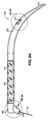
図6A~6Dは、気管切開拡張器500の第5の例示的な実施形態を示す。気管切開拡張器500は、遠位部分502、ハンドル部分504、近位部分506、及び貫通して延びる内腔を含むことができる。 6A-6D illustrate a fifth exemplary embodiment of a
遠位部分502は、ハンドル部分504から、内腔の遠位開口部を有する遠位先端510まで延びる連続的曲線を含むことができる。連続的曲線は、気管切開拡張器500が挿入中に気管を通過すること、及び遠位先端510が後気管壁をクリアすることを可能にすることができる。遠位部分502は、挿入を容易にするために、連続的曲線に沿って遠位先端510までテーパーを付けることができる。例えば、遠位部分502は、遠位先端510まで連続曲線に沿って徐々に減少する壁厚を介してテーパーを付けることができる。遠位部分502は、気管切開への挿入の際の摩擦を低減し、潤滑ゼリーの必要性を排除するために親水性コーティングを有することができる。また、遠位部分502は、遠位部分502の断面サイズ及び深さの指標512を含むことができる。例えば、図6Dに示されているように、指標512は、直径(例えば、38フレンチ)と、気管切開を拡張するための遠位部分502の挿入の適切な深さを示す少なくとも部分的に円周廻りの線と、を含むことができる。
ハンドル部分504は、実質的に直線であり、遠位部分502と一体的に形成された細長い直線状のシャフトを含むことができる。ハンドル部分504は、遠位部分502の近位にあって、ユーザによって把持されるように構成することができる。ハンドル部分504は、ユーザのグリップ及び操作性を向上させるためにテクスチャ化することができる。例えば、ハンドル部分504は、シャフト上にテクスチャ付きゴムスリーブ514を含むことができる。テクスチャ化された表面上のグリップは、ハンドル部分504及び/又はスリーブ514の長さに沿って、複数の隆起した単語及び/又はロゴ(LOGO)(例えば、製造者及び/又は販売者の)をエンボス加工することによって強化することができる。スリーブ514は、相対的な滑りを防止するために、シャフトの外面上の細長い凹部に受け入れることができる。
近位部分506は、ハンドル部分504の長手方向軸から少なくとも30~45度の角度でガイドワイヤ20を偏位させるように構成することができる。近位部分506は、ハンドル部分504の細長い直線状シャフトから着脱可能とすることができる。例えば、近位部分506は、ハンドル部分504のシャフト内に摩擦を有して受け入れられる遠位管状延長部530(図6Cに示すように)を含むことができる。遠位管状延長部530は、ハンドル部分504から一様に延びる管状部分532よりも小さい直径を有することができる。近位部分506は、ハンドル部分504の長手方向軸に対して少なくとも30~45度の角度で管状部分532から延びる角度付き軸外延長部534を更に含むことができる。角度付き延長部534は、内腔の近位開口部518を含むことができ、これを介して偏位されたガイドワイヤ20は、前進したときに気管切開拡張器500から外に通過する。図6Bに示されているように、近位部分506は、近位部分506の長手方向軸の廻りに回転して、角度付き延長部534及び近位開口部518を何れかの半径方向に配置することができる。近位部分506の回転により、例えば、ユーザの所望の把持及び/又はユーザが右利きであるか又は左利きであるかに応じて、ガイドワイヤ20の再配向が可能になる。従って、近位部分506は、ハンドル部分504を把持したときにガイドワイヤ20の挟み込みを低減又は防止することができる。
本発明の多くの特徴及び利点は、詳細な説明から明らかであり、従って、添付の特許請求の範囲は、本発明の真の精神及び範囲内にあるこのような本発明の特徴及び利点を全て包含するものとする。更に、数多くの変更形態及び変形形態が当業者には容易に想起されることになるので、本発明を図示し説明した正確な構造及び動作に限定することは望ましくなく、従って、全ての適切な変更形態及び等価物は、本発明に用いることができ、本発明の範囲内にある。 The many features and advantages of the invention are apparent from the detailed description, and it is therefore intended that the appended claims reflect all such features and advantages of the invention as fall within the true spirit and scope of the invention. shall be included. Furthermore, since numerous modifications and variations will readily occur to those skilled in the art, it is not desired to limit the invention to the precise structure and operation shown and described, and therefore all suitable Modifications and equivalents may be used with the invention and are within the scope of the invention.
20 ガイドワイヤ
100 気管切開拡張器
102 遠位部分
104 ハンドル部分
106 近位部分
110 遠位先端
112 指標
114 スリーブ
116 ベベル
118 近位開口部20
Claims (13)
Translated fromJapanese直線状であり且つユーザーによって把持されるように構成されたハンドル部分と、
このハンドル部分から前記気管切開用拡張器の遠位開口部まで延びて且つ気管切開部を拡張するように構成された湾曲する遠位部分と、を備え、
前記ハンドル部分及び前記湾曲する遠位部分は、ガイドワイヤを受け入れるように構成された内腔を形成しており、
前記気管切開用拡張器は、さらに、前記ハンドル部分の近位にあり、前記内腔と連通する近位開口部を有する近位部分を備え、
前記近位部分で且つ前記近位開口部ではない部分は、前記ハンドル部分の長手方向軸から少なくとも30度の角度で前記ガイドワイヤを偏位させるように構成されている、気管切開用拡張器。A tracheostomy dilator, comprising:
a handle portion that is linear and configured to be grasped by a user;
a curved distal portionextendingfrom the handle portion to a distal opening of the tracheostomy dilator and configured to dilatea tracheostomy;
the handle portion and the curved distal portiondefine a lumen configured to receive a guidewire;
The tracheostomy dilator further includes a proximal portion proximal to the handle portion and having a proximal opening communicating with the lumen;
The tracheostomy dilator, wherein the proximal portion and the portion that is not the proximal opening is configured to deflect the guidewire at an angle of at least 30 degrees from the longitudinal axis of the handle portion.
Applications Claiming Priority (3)
| Application Number | Priority Date | Filing Date | Title |
|---|---|---|---|
| US201962848310P | 2019-05-15 | 2019-05-15 | |
| US62/848,310 | 2019-05-15 | ||
| PCT/IB2020/054638WO2020230103A1 (en) | 2019-05-15 | 2020-05-15 | Tracheostomy dilator |
Publications (2)
| Publication Number | Publication Date |
|---|---|
| JP2022533960A JP2022533960A (en) | 2022-07-27 |
| JP7369792B2true JP7369792B2 (en) | 2023-10-26 |
Family
ID=70775454
Family Applications (1)
| Application Number | Title | Priority Date | Filing Date |
|---|---|---|---|
| JP2021568262AActiveJP7369792B2 (en) | 2019-05-15 | 2020-05-15 | tracheostomy dilator |
Country Status (6)
| Country | Link |
|---|---|
| US (2) | US12121658B2 (en) |
| EP (1) | EP3969088B1 (en) |
| JP (1) | JP7369792B2 (en) |
| CN (2) | CN118903632A (en) |
| ES (1) | ES2960928T3 (en) |
| WO (1) | WO2020230103A1 (en) |
Citations (5)
| Publication number | Priority date | Publication date | Assignee | Title |
|---|---|---|---|---|
| US20040087991A1 (en) | 2002-10-31 | 2004-05-06 | Louis Woo | Dilators |
| WO2008009943A1 (en) | 2006-07-21 | 2008-01-24 | Smiths Group Plc | Dilators |
| WO2011103629A1 (en) | 2010-02-25 | 2011-09-01 | Mondo Medical Devices Pty Ltd | Device and method for providing an airway |
| WO2016207583A1 (en) | 2015-06-24 | 2016-12-29 | Smiths Medical International Limited | Tube introducers. assemblies and methods |
| JP2017164423A (en) | 2016-03-18 | 2017-09-21 | テルモ株式会社 | Catheter assembly |
Family Cites Families (199)
| Publication number | Priority date | Publication date | Assignee | Title |
|---|---|---|---|---|
| US672377A (en) | 1900-03-27 | 1901-04-16 | William D Kearns | Dilator. |
| US2564118A (en) | 1949-07-15 | 1951-08-14 | Aloe Company As | Thyroidectomy retractor |
| US3443564A (en) | 1965-06-22 | 1969-05-13 | Drager Otto H | Tracheal tube |
| US3511243A (en) | 1967-07-18 | 1970-05-12 | Frederic J Toy | Apparatus for providing a breathing conduit communicating with the trachea at the base of the neck |
| US3754554A (en) | 1972-02-22 | 1973-08-28 | H Felbarg | Endotracheal tube means |
| US3916903A (en) | 1973-07-20 | 1975-11-04 | Reta M H Pozzi | Cricothyroid puncture apparatus |
| SE375908B (en) | 1973-12-04 | 1975-05-05 | Stille Werner Ab | |
| US3908637A (en) | 1974-04-22 | 1975-09-30 | Louis W Doroshow | Rigid urethral instrument |
| US3908665A (en) | 1974-05-20 | 1975-09-30 | John A Moses | Oro-pharyngeal airway |
| US3957055A (en) | 1974-09-23 | 1976-05-18 | Linder Gerald S | Catheter guide |
| US4100246A (en) | 1976-06-21 | 1978-07-11 | Dow Corning Corporation | Method of forming a gastrointestinal tube |
| US4067331A (en) | 1976-07-23 | 1978-01-10 | Berman Robert A | Intubating pharyngeal airway |
| US4054135A (en) | 1976-07-23 | 1977-10-18 | Berman Robert A | Intubating pharyngeal airway |
| US4211234A (en) | 1978-08-24 | 1980-07-08 | Joseph Fisher | Endotracheal tube introducer |
| US4338930A (en) | 1980-09-08 | 1982-07-13 | Tudor Williams R | Airway intubator |
| US4364391A (en) | 1980-11-14 | 1982-12-21 | Toye Frederic J | Tracheostomy apparatus and method |
| DE3115192C2 (en) | 1981-04-15 | 1983-05-19 | Christian Prof. Dr.med. 2400 Lübeck Krüger | Medical instrument |
| DE3119854A1 (en) | 1981-05-19 | 1982-12-16 | Drägerwerk AG, 2400 Lübeck | DEVICE FOR POSITIONING A TRACHEAL TUBE |
| US4405314A (en) | 1982-04-19 | 1983-09-20 | Cook Incorporated | Apparatus and method for catheterization permitting use of a smaller gage needle |
| JPS59502134A (en) | 1982-10-08 | 1984-12-27 | ハ−ドキャッスル、ディビッド | Opening device to body cavity |
| US4531933A (en) | 1982-12-07 | 1985-07-30 | C. R. Bard, Inc. | Helical ureteral stent |
| US4512765A (en) | 1983-06-09 | 1985-04-23 | Rudolph Muto | Selective tracheal bronchial catheter |
| US5186168A (en) | 1984-11-21 | 1993-02-16 | Spofford Bryan T | Transtracheal catheter system and method |
| US5090408A (en) | 1985-10-18 | 1992-02-25 | Bryan T. Spofford | Transtracheal catheter system and method |
| US4762128A (en) | 1986-12-09 | 1988-08-09 | Advanced Surgical Intervention, Inc. | Method and apparatus for treating hypertrophy of the prostate gland |
| US4893623A (en) | 1986-12-09 | 1990-01-16 | Advanced Surgical Intervention, Inc. | Method and apparatus for treating hypertrophy of the prostate gland |
| US4771776A (en) | 1987-01-06 | 1988-09-20 | Advanced Cardiovascular Systems, Inc. | Dilatation catheter with angled balloon and method |
| US4832020A (en) | 1987-03-24 | 1989-05-23 | Augustine Scott D | Tracheal intubation guide |
| US5042469A (en) | 1987-03-24 | 1991-08-27 | Augustine Medical, Inc. | Tracheal intubation guide |
| US5058580A (en) | 1988-05-11 | 1991-10-22 | Hazard Patrick B | Percutaneous tracheostomy tube |
| US4978334A (en) | 1988-09-08 | 1990-12-18 | Toye Frederic J | Apparatus and method for providing passage into body viscus |
| US5042475A (en) | 1988-09-30 | 1991-08-27 | Portex, Inc. | Hinged tracheostomy tube obturator |
| US5209735A (en) | 1988-11-07 | 1993-05-11 | Lazarus Harrison M | External guide wire and enlargement means |
| US4966583A (en) | 1989-02-03 | 1990-10-30 | Elie Debbas | Apparatus for locating a breast mass |
| US5183463A (en) | 1989-02-03 | 1993-02-02 | Elie Debbas | Apparatus for locating a breast mass |
| US4898163A (en) | 1989-02-27 | 1990-02-06 | George Gordon P | Transtracheal airway and placement device |
| USRE34086E (en) | 1989-02-27 | 1992-10-06 | Medical placement device | |
| US6299628B1 (en) | 1989-08-25 | 2001-10-09 | Scimed Life Systems, Inc. | Method and apparatus for catheter exchange |
| US5484409A (en) | 1989-08-25 | 1996-01-16 | Scimed Life Systems, Inc. | Intravascular catheter and method for use thereof |
| EP0415332B1 (en) | 1989-08-25 | 1995-01-11 | SciMed Life Systems, Inc. | Apparatus for catheter exchange by guide wire captivation |
| US5169386A (en) | 1989-09-11 | 1992-12-08 | Bruce B. Becker | Method and catheter for dilatation of the lacrimal system |
| US5021043A (en) | 1989-09-11 | 1991-06-04 | C. R. Bard, Inc. | Method and catheter for dilatation of the lacrimal system |
| US5515844A (en) | 1989-11-02 | 1996-05-14 | Christopher; Kent L. | Method and apparatus for weaning ventilator-dependent patients |
| WO1991008709A1 (en) | 1989-12-11 | 1991-06-27 | William Middleton Griggs | Tracheostomy method and apparatus |
| US5263931A (en) | 1990-02-14 | 1993-11-23 | Advanced Cardiovascular Systems, Inc. | Balloon catheter for dilating a prostatic urethra |
| US5034005A (en) | 1990-07-09 | 1991-07-23 | Appling William M | Radiopaque marker |
| US5143093A (en) | 1990-10-05 | 1992-09-01 | Harvinder Sahota | Methods of angioplasty treatment of stenotic regions |
| DE69123982T2 (en) | 1990-11-20 | 1997-12-04 | Innerdyne Medical Inc | STRETCH MAINTENANCE GUIDE ELEMENT AND DILATATOR |
| US5209725A (en) | 1991-04-11 | 1993-05-11 | Roth Robert A | Prostatic urethra dilatation catheter system and method |
| US5217007A (en) | 1991-04-26 | 1993-06-08 | Cook Incorporated | Speculum for forming an ostomy in a trachea |
| US5183464A (en) | 1991-05-17 | 1993-02-02 | Interventional Thermodynamics, Inc. | Radially expandable dilator |
| US5395335A (en) | 1991-05-24 | 1995-03-07 | Jang; G. David | Universal mode vascular catheter system |
| US5188100A (en) | 1991-09-09 | 1993-02-23 | New York University | Apparatus for facilitating tracheostomy tube replacement |
| EP0539084A1 (en) | 1991-10-18 | 1993-04-28 | Imagyn Medical, Inc. | Apparatus and method for independent movement of an instrument within a linear eversion catheter |
| US5364345A (en) | 1991-10-18 | 1994-11-15 | Imagyn Medical, Inc. | Method of tubal recanalization and catheter system therefor |
| US5217005A (en) | 1991-11-01 | 1993-06-08 | Weinstein James D | Apparatus for performing percutaneous tracheostomies and cricothyroidectomies |
| US5197465A (en) | 1991-12-17 | 1993-03-30 | Boston Medical Products, Inc. | Gauge for measuring tracheotomy stoma |
| US5246421A (en) | 1992-02-12 | 1993-09-21 | Saab Mark A | Method of treating obstructed regions of bodily passages |
| US5259371A (en) | 1992-08-13 | 1993-11-09 | Tonrey Francis G | Endotracheal tube and method of intubation |
| US5338296A (en) | 1993-01-06 | 1994-08-16 | Ethicon, Inc. | Catheter and sheath assembly |
| US5752932A (en) | 1993-04-29 | 1998-05-19 | Scimed Life Systems, Inc. | Intravascular catheter with a recoverable guide wire lumen and method of use |
| US5549553A (en) | 1993-04-29 | 1996-08-27 | Scimed Life Systems, Inc. | Dilation ballon for a single operator exchange intravascular catheter or similar device |
| US5382238A (en) | 1993-05-20 | 1995-01-17 | Quinton Instrument Company | Catheter stiffeners |
| US5389074A (en) | 1993-10-27 | 1995-02-14 | The Regents Of The University Of California | Body insertion tube with anesthetic jacket |
| US5749357A (en) | 1995-05-19 | 1998-05-12 | Linder; Gerald S. | Malleable introducer |
| US5891057A (en) | 1995-10-04 | 1999-04-06 | Chaisson; Gary A. | Carotid artery angioplasty guiding system |
| US5697365A (en) | 1996-01-18 | 1997-12-16 | Pell; Donald M. | Endotracheal tube construction and method for intubating a patient |
| US5653230A (en) | 1996-01-19 | 1997-08-05 | Cook Incorporated | Percutaneous balloon dilational tracheostomy tube |
| US5623924A (en) | 1996-03-29 | 1997-04-29 | Lindenman; Tammy S. | Apparatus and method for retaining an endotracheal tube |
| US5669380A (en) | 1996-04-26 | 1997-09-23 | New England Medical Center Hospitals, Inc. | Laryngeal bypass |
| US5904648A (en) | 1996-06-18 | 1999-05-18 | Cook Incorporated | Guided endobronchial blocker catheter |
| US6520951B1 (en) | 1996-09-13 | 2003-02-18 | Scimed Life Systems, Inc. | Rapid exchange catheter with detachable hood |
| US6096009A (en) | 1996-09-13 | 2000-08-01 | Boston Scientific Corporation | Guidewire and catheter locking device and method |
| US6007522A (en) | 1996-09-13 | 1999-12-28 | Boston Scientific Corporation | Single operator exchange biliary catheter |
| US6346093B1 (en) | 1996-09-13 | 2002-02-12 | Scimed Life Systems, Inc. | Single operator exchange biliary catheter with common distal lumen |
| US5921971A (en) | 1996-09-13 | 1999-07-13 | Boston Scientific Corporation | Single operator exchange biliary catheter |
| US6606515B1 (en) | 1996-09-13 | 2003-08-12 | Scimed Life Systems, Inc. | Guide wire insertion and re-insertion tools and methods of use |
| US6582401B1 (en) | 1996-09-13 | 2003-06-24 | Scimed Life Sytems, Inc. | Multi-size convertible catheter |
| US6010520A (en) | 1998-05-01 | 2000-01-04 | Pattison; C. Phillip | Double tapered esophageal dilator |
| AUPQ362199A0 (en) | 1999-10-22 | 1999-11-18 | Kaladelfos, George | Intra-vaginal sling placement device |
| GB9926570D0 (en) | 1999-11-11 | 2000-01-12 | Smiths Industries Plc | Tracheostomy tube assemblies and obturators |
| US6637435B2 (en) | 1999-12-07 | 2003-10-28 | Cook Incorporated | Percutaneous dilational device |
| US6530898B1 (en) | 2000-04-20 | 2003-03-11 | Tyco Healthcare Group Lp | Visual inflation pressure indicator and surgical tube including the indicator |
| DE10025314A1 (en) | 2000-05-22 | 2001-12-06 | Ruesch Willy Ag | Tracheotomy procedure and instrument |
| US6820614B2 (en) | 2000-12-02 | 2004-11-23 | The Bonutti 2003 Trust -A | Tracheal intubination |
| TWI304076B (en) | 2001-07-13 | 2008-12-11 | Nippon Catalytic Chem Ind | |
| US6638253B2 (en) | 2001-07-17 | 2003-10-28 | Eugene Michael Breznock | Method and apparatus for chest drainage |
| GB0130156D0 (en) | 2001-12-18 | 2002-02-06 | Smiths Group Plc | Medico-surgical apparatus |
| GB0201436D0 (en) | 2002-01-23 | 2002-03-13 | Smiths Group Plc | Medico-surgical apparatus |
| ES2259406T3 (en) | 2002-08-24 | 2006-10-01 | Smiths Group Plc | MEDICAL-SURGICAL INSTRUMENTS. |
| USD485358S1 (en) | 2002-10-31 | 2004-01-13 | Smiths Group Plc | Dilator |
| US7316708B2 (en) | 2002-12-05 | 2008-01-08 | Cardiac Dimensions, Inc. | Medical device delivery system |
| US6705320B1 (en) | 2002-12-23 | 2004-03-16 | Scott M. Anderson | Methods for performing tracheal intubation on an animal and endotracheal tubes therefore |
| US6792948B2 (en) | 2003-01-22 | 2004-09-21 | Archibald I. J. Brain | Laryngeal mask airway device with airway tube having flattened outer circumference and elliptical inner airway passage |
| WO2004069316A2 (en) | 2003-02-03 | 2004-08-19 | Cook Critical Care | Tracheostomy tube dilator |
| US20040255951A1 (en) | 2003-02-07 | 2004-12-23 | Christopher Grey | Endotrachael tube with suction catheter and system |
| US20040167439A1 (en)* | 2003-02-26 | 2004-08-26 | Sharrow James S. | Guidewire having textured proximal portion |
| DE602004016310D1 (en) | 2003-04-25 | 2008-10-16 | Cook Inc | SUPPLY CATHETER |
| US7036510B2 (en) | 2003-04-28 | 2006-05-02 | Cook Critical Care Incorporated | Percutaneous tracheostomy balloon apparatus |
| US7811303B2 (en) | 2003-08-26 | 2010-10-12 | Medicine Lodge Inc | Bodily tissue dilation systems and methods |
| JP2005095401A (en)* | 2003-09-25 | 2005-04-14 | Nippon Sherwood Medical Industries Ltd | Tracheal dilator |
| EP1570878B1 (en) | 2004-03-01 | 2008-06-11 | Terumo Kabushiki Kaisha | Device for introduction of long medical item |
| US7650886B1 (en) | 2004-03-04 | 2010-01-26 | Christian Keller | Esophageal airway management device guides |
| WO2005096940A1 (en) | 2004-04-08 | 2005-10-20 | Philip Stuart Esnouf | A hearing testing device |
| US20060004398A1 (en) | 2004-07-02 | 2006-01-05 | Binder Lawrence J Jr | Sequential dilator system |
| EP1796768A2 (en) | 2004-07-12 | 2007-06-20 | Bioservice S.p.A. | Tracheostomy apparatus |
| US7341061B2 (en) | 2004-12-15 | 2008-03-11 | Scott Douglas Wood | Tracheostomy system |
| GB0503082D0 (en) | 2005-02-15 | 2005-03-23 | Smiths Group Plc | Medico-surgical apparatus |
| EP1853339A1 (en) | 2005-02-15 | 2007-11-14 | Patents Exploitation Company B.V. | Dilatative percutaneous tracheotomy device |
| EP1898981B1 (en) | 2005-06-27 | 2014-04-16 | Cook Medical Technologies LLC | A dilator for performing a percutaneous medical procedure |
| US7921847B2 (en) | 2005-07-25 | 2011-04-12 | Intubix, Llc | Device and method for placing within a patient an enteral tube after endotracheal intubation |
| US7647929B2 (en) | 2005-09-28 | 2010-01-19 | Nellcor Puritan Bennett Llc | Medical device tube having a flange with opposing support ears for improved alignment and retention of an inner cannula in an outer cannula |
| US7600515B2 (en) | 2005-09-28 | 2009-10-13 | Nellcor Puritan Bennett Llc | Tracheostomy tube combination radial snap and bayonet cannula connector |
| US7267124B1 (en) | 2006-02-07 | 2007-09-11 | Roberson Jr Travis Hubert | Emergency tracheostomy kit |
| US7373939B1 (en) | 2006-03-03 | 2008-05-20 | Cardica, Inc. | Tracheotomy procedure with integrated tool |
| JP5191005B2 (en) | 2006-05-18 | 2013-04-24 | ブリーズ テクノロジーズ, インコーポレイテッド | Method and device for tracheostomy |
| DE102006029599A1 (en) | 2006-06-26 | 2007-12-27 | Tracoe Medical Gmbh | Device for introducing a tracheostomy tube into a tracheostoma |
| DE102006035887A1 (en) | 2006-07-31 | 2008-02-07 | Tracoe Medical Gmbh | Tracheostomy cannula with inner cannula |
| ES2638430T3 (en) | 2006-09-22 | 2017-10-20 | Romano Guerra | Tracheostomy device and device |
| US20090306472A1 (en) | 2007-01-18 | 2009-12-10 | Filipi Charles J | Systems and techniques for endoscopic dilation |
| GB0705271D0 (en)* | 2007-03-20 | 2007-04-25 | Smiths Group Plc | Tracheostomy devices |
| EP2134398A4 (en) | 2007-04-11 | 2014-06-25 | John J Davis | Atraumatic introducer for nasal endotracheal tubes and its method of use |
| US20090024089A1 (en) | 2007-04-25 | 2009-01-22 | Levine Jonathan A | Long tapered dilator |
| US8424534B2 (en) | 2007-05-01 | 2013-04-23 | Cook Medical Technologies Llc | Loading dilator with transition balloon |
| WO2008144589A1 (en) | 2007-05-18 | 2008-11-27 | Breathe Technologies, Inc. | Methods and devices for sensing respiration and providing ventilation therapy |
| WO2009010070A1 (en) | 2007-07-13 | 2009-01-22 | Coloplast A/S | A tip for an insertion device |
| EP3199094B1 (en) | 2007-08-28 | 2020-10-21 | Aircraft Medical Limited | Laryngoscope insertion section |
| GB0716672D0 (en) | 2007-08-28 | 2007-10-03 | Aircraft Medical Ltd | Laryngoscope |
| US8313687B2 (en) | 2007-09-20 | 2012-11-20 | Kimberly-Clark Worldwide, Inc. | Method of making an improved balloon cuff tracheostomy tube |
| US20090209908A1 (en) | 2007-09-20 | 2009-08-20 | Cuevas Brian J | Tubular workpiece for producing an improved balloon cuff tracheostomy tube |
| US8607795B2 (en) | 2007-09-20 | 2013-12-17 | Kimberly-Clark Worldwide, Inc. | Balloon cuff tracheostomy tube |
| US20090090365A1 (en) | 2007-09-20 | 2009-04-09 | Cuevas Brian J | Balloon cuff tracheostomy tube with greater ease of insertion |
| US8820319B2 (en) | 2007-10-04 | 2014-09-02 | Ai Medical Devices, Inc. | Guide device for tracheal intubation |
| BRPI0818608A2 (en) | 2007-10-05 | 2015-04-22 | Synthes Gmbh | Sequential directional dilatation system for dilating from a nerve of a patient's anatomy, and method for forming an access opening through a psoas muscle to a patient's spine using a dilatation system |
| EP2072074A1 (en) | 2007-12-19 | 2009-06-24 | Roger Isla | Tracheostomy device |
| US20090163942A1 (en) | 2007-12-20 | 2009-06-25 | Cuevas Brian J | Tracheostomy punch dilator |
| TW200932296A (en) | 2008-01-31 | 2009-08-01 | Tien-Sheng Chen | Clip device and laryngeal mask airway |
| US8186353B1 (en) | 2008-02-11 | 2012-05-29 | Lejeune Francis E | Emergency tracheotomy tube and package |
| US20120095432A1 (en) | 2010-10-15 | 2012-04-19 | Nath Iyunni Venkata Sesha Sayi | Catheter and method of insertion |
| US7975696B2 (en) | 2008-04-14 | 2011-07-12 | Helix Medical, Llc | Voice prosthesis dilator/sizer |
| US20090320854A1 (en) | 2008-06-27 | 2009-12-31 | Cuevas Brian J | Easy Grip Tapered Dilator |
| US8307824B2 (en) | 2008-06-27 | 2012-11-13 | Kimberly-Clark Worldwide, Inc. | Method of performing a tracheostomy |
| USD605759S1 (en) | 2008-06-27 | 2009-12-08 | Kimberly-Clark Worldwide, Inc. | Dilator handle |
| US20090320834A1 (en)* | 2008-06-27 | 2009-12-31 | Cuevas Brian J | Dilator Loading Catheter |
| US20100065062A1 (en) | 2008-09-17 | 2010-03-18 | Wolfe Tory Medical, Inc. | Temporary pharyngeal airway |
| US20100114147A1 (en) | 2008-10-30 | 2010-05-06 | The University Of Toledo | Directional soft tissue dilator and docking pin with integrated light source for optimization of retractor placement in minimally invasive spine surgery |
| GB2492000B (en)* | 2008-10-31 | 2013-05-08 | Daniela Andrich | Dilatation device |
| US9265907B2 (en) | 2008-12-30 | 2016-02-23 | Cook Medical Technologies Llc | Self-centering tracheostomy tube |
| GB0903611D0 (en) | 2009-03-03 | 2009-04-08 | Aircraft Medical Ltd | Laryngoscope insertion section with tube guide for guiding endotracheal tubes having a range of external diameters |
| US20100224187A1 (en) | 2009-03-04 | 2010-09-09 | Thomas Maxwell Dalton | Apparatus and methods facilitating atraumatic intubation |
| US8151791B2 (en) | 2009-04-29 | 2012-04-10 | Lifeserve Innovations, Llc | Methods and devices for performing an emergency or non-emergency tracheotomy |
| US20100300449A1 (en) | 2009-05-28 | 2010-12-02 | Chan Sam C | Position Indicator for Tracheostomy Tube |
| US20100300448A1 (en) | 2009-05-28 | 2010-12-02 | Kenowski Michael A | Tracheostomy Tube |
| US20100300451A1 (en) | 2009-06-01 | 2010-12-02 | Griffith Nathan C | Punch Dilator |
| CN102458308B (en) | 2009-06-16 | 2015-06-03 | 阿托斯医疗公司 | Dilator for inserting a voice prozhesis |
| DE102009028083A1 (en) | 2009-07-29 | 2011-02-10 | Schönhage, Kai, Dr., Tucson | intubation |
| EP2281594B1 (en) | 2009-07-31 | 2012-04-18 | SafeTrach AB | A dilator assembly and device for facilitating tracheostomy |
| HRP20090463A2 (en) | 2009-08-31 | 2011-03-31 | Golf Vizija D.O.O. | Curved dilator for targer thoracic drainage |
| US8887717B2 (en) | 2009-10-15 | 2014-11-18 | Airway Cam Technologies, Inc. | Introducer for surgical airway catheters |
| WO2011047232A1 (en) | 2009-10-15 | 2011-04-21 | Airway Cam Technologies, Inc. | Introducer for surgical airway catheters |
| US8474450B2 (en) | 2009-11-12 | 2013-07-02 | Jose Pablo Diaz Jimenez | Enhancements introduced into prolonged tracheal cannulation processes |
| DE102009054573A1 (en) | 2009-11-13 | 2011-05-19 | Tracoe Medical Gmbh | Tracheostomy tube with window |
| US20110265797A1 (en) | 2010-04-30 | 2011-11-03 | Nellcor Puritan Bennett Llc | Extendable tracheal tube |
| US20110290245A1 (en) | 2010-05-27 | 2011-12-01 | Cuevas Brian J | Internally Braced Radial Balloon Dilator |
| US20120017913A1 (en) | 2010-07-26 | 2012-01-26 | Schumacher James F | Tracheostomy Tube Loading Catheter |
| US20120017916A1 (en)* | 2010-07-26 | 2012-01-26 | Schumacher James F | Dilator With Integrated Guiding Catheter |
| EP2627387B1 (en) | 2010-10-15 | 2018-08-15 | Teleflex Life Sciences Unlimited Company | Artificial airway device |
| GB2485762B (en) | 2010-11-12 | 2012-12-05 | Cook Medical Technologies Llc | Introducer assembly and dilator tip therefor |
| EP2465563B1 (en) | 2010-12-14 | 2013-03-06 | Gimac di Maccagnan Giorgio | Tracheotomy device |
| US8899225B2 (en) | 2011-01-19 | 2014-12-02 | Cook Medical Technologies Llc | Percutaneous dilational device having balloon retention mechanism |
| ITRM20110258A1 (en) | 2011-05-25 | 2012-11-26 | Servillo Giuseppe | TRANSLARINGEA TRACHEOTOMY EQUIPMENT. |
| US20130025588A1 (en) | 2011-07-26 | 2013-01-31 | Cook Medical Technologies Llc | Loading dilator |
| US20130255694A1 (en) | 2012-03-28 | 2013-10-03 | Lifeserve Innovations Llc | Percutaneous dilatational device |
| US20130269705A1 (en) | 2012-04-16 | 2013-10-17 | Thomas C. Kochem | Variable stiffness flexure |
| US20130317439A1 (en) | 2012-05-25 | 2013-11-28 | Arstasis, Inc. | Vascular access configuration |
| US8876848B2 (en) | 2012-06-06 | 2014-11-04 | Stewart And Stien Enterprises, Llc | Dilator and elongate guide wire and method of using same |
| GB201210027D0 (en) | 2012-06-07 | 2012-07-18 | Cambridge University Hospitals Nhs Foundation Trust | Stoma-creating device |
| US9089663B2 (en) | 2012-06-28 | 2015-07-28 | Cook Medical Technologies Llc | Percutaneous access device |
| US9572623B2 (en) | 2012-08-02 | 2017-02-21 | Ethicon Endo-Surgery, Inc. | Reusable electrode and disposable sheath |
| AU2013299322A1 (en)* | 2012-08-03 | 2014-09-25 | Mondo Medical Devices Pty Ltd | Airway opening apparatus and method |
| US10166353B2 (en) | 2012-10-14 | 2019-01-01 | Evgeny Pecherer | Tool and method for inserting an endotracheal tube |
| US9393374B2 (en) | 2013-03-25 | 2016-07-19 | Richard M. Levitan | Introducer for surgical airway catheters |
| US9555206B1 (en)* | 2013-05-22 | 2017-01-31 | Mark Edward Tellam | Dilator device |
| CA2923628C (en) | 2013-09-23 | 2019-12-03 | Event Horizon Limited | Emergency tracheotomy device |
| CA3014125C (en) | 2013-09-26 | 2021-01-26 | Innovital Llc | Assist device for medical procedures |
| US9770194B2 (en) | 2013-11-05 | 2017-09-26 | Ciel Medical, Inc. | Devices and methods for airway measurement |
| CN103735297B (en) | 2013-11-29 | 2016-06-01 | 冯清亮 | A kind of classification expansion through skin trachea incising apparatus |
| US9700312B2 (en) | 2014-01-28 | 2017-07-11 | Covidien Lp | Surgical apparatus |
| US10569060B2 (en)* | 2014-07-09 | 2020-02-25 | Acclarent, Inc. | Guide catheters with guidewire deflection features |
| US11633093B2 (en)* | 2014-08-08 | 2023-04-25 | Wm & Dg, Inc. | Medical devices and methods of placement |
| US20160106940A1 (en) | 2014-10-15 | 2016-04-21 | Cook Medical Technologies Llc | Tube tip bevel to aid wire guide insertion |
| DE102014117368A1 (en)* | 2014-11-26 | 2016-06-02 | Tracoe Medical Gmbh | Dilator for percutaneous dilatation tracheostomy |
| JP6727757B2 (en) | 2015-03-30 | 2020-07-22 | 株式会社グッドマン | catheter |
| EP3376937B1 (en) | 2015-11-19 | 2021-10-13 | Sainath Intellectual Properties, LLC | Dilator with slit and slidable sleeve |
| DE102015122810A1 (en)* | 2015-12-23 | 2017-06-29 | Tracoe Medical Gmbh | insertion |
| CA3008028A1 (en) | 2016-01-07 | 2017-07-13 | Glenn P. Gardner | Endotracheal tube insertion device |
| US10286171B2 (en) | 2016-01-07 | 2019-05-14 | Glenn P. Gardner | Endotracheal tube insertion device |
| GB201607675D0 (en) | 2016-04-30 | 2016-06-15 | Smiths Medical Int Ltd | Tracheostomy procedure kits and guiding catheters |
| DE202017002009U1 (en)* | 2017-04-15 | 2017-06-02 | Primed Halberstadt Medizintechnik Gmbh | System for inserting a tracheostomy tube into a tracheostoma |
- 2020
- 2020-05-15JPJP2021568262Apatent/JP7369792B2/enactiveActive
- 2020-05-15EPEP20726963.0Apatent/EP3969088B1/enactiveActive
- 2020-05-15WOPCT/IB2020/054638patent/WO2020230103A1/ennot_activeCeased
- 2020-05-15ESES20726963Tpatent/ES2960928T3/enactiveActive
- 2020-05-15CNCN202411068912.2Apatent/CN118903632A/enactivePending
- 2020-05-15CNCN202080048423.4Apatent/CN114502226B/enactiveActive
- 2021
- 2021-11-14USUS17/525,940patent/US12121658B2/enactiveActive
- 2024
- 2024-10-21USUS18/922,236patent/US20250152882A1/enactivePending
Patent Citations (8)
| Publication number | Priority date | Publication date | Assignee | Title |
|---|---|---|---|---|
| US20040087991A1 (en) | 2002-10-31 | 2004-05-06 | Louis Woo | Dilators |
| JP2004148122A (en) | 2002-10-31 | 2004-05-27 | Smiths Group Plc | Dilator |
| WO2008009943A1 (en) | 2006-07-21 | 2008-01-24 | Smiths Group Plc | Dilators |
| JP2009544344A (en) | 2006-07-21 | 2009-12-17 | スミスズ グループ ピーエルシー | Dilator |
| WO2011103629A1 (en) | 2010-02-25 | 2011-09-01 | Mondo Medical Devices Pty Ltd | Device and method for providing an airway |
| WO2016207583A1 (en) | 2015-06-24 | 2016-12-29 | Smiths Medical International Limited | Tube introducers. assemblies and methods |
| JP2018518316A (en) | 2015-06-24 | 2018-07-12 | スミスズ メディカル インターナショナル リミテッド | Tube introducer, assembly and method |
| JP2017164423A (en) | 2016-03-18 | 2017-09-21 | テルモ株式会社 | Catheter assembly |
Also Published As
| Publication number | Publication date |
|---|---|
| WO2020230103A1 (en) | 2020-11-19 |
| EP3969088A1 (en) | 2022-03-23 |
| US12121658B2 (en) | 2024-10-22 |
| ES2960928T3 (en) | 2024-03-07 |
| CN118903632A (en) | 2024-11-08 |
| EP3969088B1 (en) | 2023-07-05 |
| US20250152882A1 (en) | 2025-05-15 |
| JP2022533960A (en) | 2022-07-27 |
| CN114502226B (en) | 2024-08-27 |
| CN114502226A (en) | 2022-05-13 |
| US20220088335A1 (en) | 2022-03-24 |
Similar Documents
| Publication | Publication Date | Title |
|---|---|---|
| JP4907945B2 (en) | Medical guidewire | |
| US20030036712A1 (en) | Roller wheel assisted guidewire advancer | |
| CA2285055C (en) | Guide wire dispenser apparatus | |
| US8652106B2 (en) | Locking guidewire straightener | |
| US5843002A (en) | Guide wire dispenser apparatus and method | |
| US5634475A (en) | Guidewire delivery assist device and system | |
| JP5140076B2 (en) | Dilator | |
| US5454787A (en) | Torquable tubular assembly and torquable catheter utilizing the same | |
| JP4447888B2 (en) | Dilator | |
| US9295813B2 (en) | Guidewire | |
| JP2004136121A5 (en) | ||
| US9474887B2 (en) | Surgical implement guide assembly and methods | |
| US9566673B2 (en) | Snare introducer | |
| JP7369792B2 (en) | tracheostomy dilator | |
| JP2022536908A (en) | microintroducer system | |
| KR101860906B1 (en) | The guide wire and the flexible catheter having that | |
| JP4827301B2 (en) | Endoscopic catheter | |
| CN220213665U (en) | A kind of guiding device for urinary catheter | |
| JP2012011247A (en) | Medical guide wire |
Legal Events
| Date | Code | Title | Description |
|---|---|---|---|
| A621 | Written request for application examination | Free format text:JAPANESE INTERMEDIATE CODE: A621 Effective date:20211217 | |
| A131 | Notification of reasons for refusal | Free format text:JAPANESE INTERMEDIATE CODE: A131 Effective date:20221214 | |
| A977 | Report on retrieval | Free format text:JAPANESE INTERMEDIATE CODE: A971007 Effective date:20221216 | |
| A601 | Written request for extension of time | Free format text:JAPANESE INTERMEDIATE CODE: A601 Effective date:20230306 | |
| A521 | Request for written amendment filed | Free format text:JAPANESE INTERMEDIATE CODE: A523 Effective date:20230613 | |
| TRDD | Decision of grant or rejection written | ||
| A01 | Written decision to grant a patent or to grant a registration (utility model) | Free format text:JAPANESE INTERMEDIATE CODE: A01 Effective date:20230914 | |
| A61 | First payment of annual fees (during grant procedure) | Free format text:JAPANESE INTERMEDIATE CODE: A61 Effective date:20231016 | |
| R150 | Certificate of patent or registration of utility model | Ref document number:7369792 Country of ref document:JP Free format text:JAPANESE INTERMEDIATE CODE: R150 |