JP7368840B2 - Environmental information analysis method - Google Patents
Environmental information analysis methodDownload PDFInfo
- Publication number
- JP7368840B2 JP7368840B2JP2019547527AJP2019547527AJP7368840B2JP 7368840 B2JP7368840 B2JP 7368840B2JP 2019547527 AJP2019547527 AJP 2019547527AJP 2019547527 AJP2019547527 AJP 2019547527AJP 7368840 B2JP7368840 B2JP 7368840B2
- Authority
- JP
- Japan
- Prior art keywords
- information
- environmental information
- aircraft
- flying object
- environmental
- Prior art date
- Legal status (The legal status is an assumption and is not a legal conclusion. Google has not performed a legal analysis and makes no representation as to the accuracy of the status listed.)
- Active
Links
- 230000007613environmental effectEffects0.000titleclaimsdescription81
- 238000004458analytical methodMethods0.000titleclaimsdescription54
- 238000000034methodMethods0.000claimsdescription6
- 238000001228spectrumMethods0.000claimsdescription5
- 230000010365information processingEffects0.000claims3
- 230000006870functionEffects0.000description7
- 230000009471actionEffects0.000description4
- 238000010586diagramMethods0.000description4
- 230000007246mechanismEffects0.000description4
- 230000007704transitionEffects0.000description4
- 238000001514detection methodMethods0.000description3
- 238000007664blowingMethods0.000description2
- 238000002474experimental methodMethods0.000description2
- 230000005484gravityEffects0.000description2
- 238000010295mobile communicationMethods0.000description2
- 238000012545processingMethods0.000description2
- OKTJSMMVPCPJKN-UHFFFAOYSA-NCarbonChemical compound[C]OKTJSMMVPCPJKN-UHFFFAOYSA-N0.000description1
- FYYHWMGAXLPEAU-UHFFFAOYSA-NMagnesiumChemical compound[Mg]FYYHWMGAXLPEAU-UHFFFAOYSA-N0.000description1
- 230000001133accelerationEffects0.000description1
- 229910045601alloyInorganic materials0.000description1
- 239000000956alloySubstances0.000description1
- XAGFODPZIPBFFR-UHFFFAOYSA-NaluminiumChemical compound[Al]XAGFODPZIPBFFR-UHFFFAOYSA-N0.000description1
- 229910052782aluminiumInorganic materials0.000description1
- 230000005540biological transmissionEffects0.000description1
- 229910052799carbonInorganic materials0.000description1
- 238000006243chemical reactionMethods0.000description1
- 238000004891communicationMethods0.000description1
- 230000010006flightEffects0.000description1
- 238000009434installationMethods0.000description1
- 229910052749magnesiumInorganic materials0.000description1
- 239000011777magnesiumSubstances0.000description1
- 238000007726management methodMethods0.000description1
- 239000000463materialSubstances0.000description1
- 230000004048modificationEffects0.000description1
- 238000012986modificationMethods0.000description1
- 238000007781pre-processingMethods0.000description1
- 230000000630rising effectEffects0.000description1
- 238000010845search algorithmMethods0.000description1
- 239000010935stainless steelSubstances0.000description1
- 229910001220stainless steelInorganic materials0.000description1
- 239000000126substanceSubstances0.000description1
Images


Classifications
- B—PERFORMING OPERATIONS; TRANSPORTING
- B64—AIRCRAFT; AVIATION; COSMONAUTICS
- B64D—EQUIPMENT FOR FITTING IN OR TO AIRCRAFT; FLIGHT SUITS; PARACHUTES; ARRANGEMENT OR MOUNTING OF POWER PLANTS OR PROPULSION TRANSMISSIONS IN AIRCRAFT
- B64D47/00—Equipment not otherwise provided for
- B—PERFORMING OPERATIONS; TRANSPORTING
- B64—AIRCRAFT; AVIATION; COSMONAUTICS
- B64U—UNMANNED AERIAL VEHICLES [UAV]; EQUIPMENT THEREFOR
- B64U10/00—Type of UAV
- B64U10/10—Rotorcrafts
- B64U10/13—Flying platforms
- B—PERFORMING OPERATIONS; TRANSPORTING
- B64—AIRCRAFT; AVIATION; COSMONAUTICS
- B64U—UNMANNED AERIAL VEHICLES [UAV]; EQUIPMENT THEREFOR
- B64U20/00—Constructional aspects of UAVs
- B64U20/70—Constructional aspects of the UAV body
- B—PERFORMING OPERATIONS; TRANSPORTING
- B64—AIRCRAFT; AVIATION; COSMONAUTICS
- B64U—UNMANNED AERIAL VEHICLES [UAV]; EQUIPMENT THEREFOR
- B64U2101/00—UAVs specially adapted for particular uses or applications
- B64U2101/30—UAVs specially adapted for particular uses or applications for imaging, photography or videography
- B—PERFORMING OPERATIONS; TRANSPORTING
- B64—AIRCRAFT; AVIATION; COSMONAUTICS
- B64U—UNMANNED AERIAL VEHICLES [UAV]; EQUIPMENT THEREFOR
- B64U30/00—Means for producing lift; Empennages; Arrangements thereof
- B64U30/20—Rotors; Rotor supports
Landscapes
- Engineering & Computer Science (AREA)
- Aviation & Aerospace Engineering (AREA)
- Mechanical Engineering (AREA)
- Remote Sensing (AREA)
- Control Of Multiple Motors (AREA)
- Traffic Control Systems (AREA)
Description
Translated fromJapanese本発明は、飛行体の周囲における環境情報を生成可能な環境情報分析方法に関する。 The present invention relates to an environmental information analysis method capable of generating environmental information around an aircraft.
近年、ドローン(Drone)や無人航空機(UAV:Unmanned Aerial Vehicle)などの飛行体(以下、「飛行体」と総称する)を利用して荷物Lの配達を行う試みがなされている。特許文献1には、飛行体による配達システムが開示されている(例えば、特許文献1参照)。 In recent years, attempts have been made to deliver luggage L using flying vehicles (hereinafter collectively referred to as "flying vehicles") such as drones and unmanned aerial vehicles (UAVs).
一般に、飛行体の飛行に対しては、安定した飛行のために飛行体の周囲における情報を得る必要がある。ところが、現状、天気予報のようなマクロな情報では、地上空域の詳細な状態はわからない。 Generally, when flying an aircraft, it is necessary to obtain information about the surroundings of the aircraft for stable flight. However, currently, macro information such as weather forecasts does not provide detailed information about the state of the ground airspace.
一方、地上にセンサ等を設置するのはコストや設置スペース確保の観点から現実的でない。On the other hand, installing sensors and the like on the ground is not realistic from the viewpoint of cost and securing installation space.
そこで、本発明は、簡易な構成で、飛行体の周囲の環境情報を取得することを目的とする。Therefore, an object of the present invention is to acquire environmental information around a flying object with a simple configuration.
本発明によれば、センサ部を備えた飛行体からセンサ情報を取得するセンサ情報取得ステップと、
前記センサ情報に基づいて前記飛行体の周囲の状態に関する状態情報を分析する状態分析ステップと、
前記分析結果に基づいて、前記飛行体の周囲における環境情報を生成する環境情報生成ステップと、
を備える環境情報分析方法が得られる。According to the present invention, a sensor information acquisition step of acquiring sensor information from an aircraft equipped with a sensor unit;
a state analysis step of analyzing state information regarding a state around the flying object based on the sensor information;
an environmental information generation step of generating environmental information around the flying object based on the analysis result;
An environmental information analysis method is obtained.
本発明によれば、制御部を備える飛行体を利用して当該飛行体の環境情報を分析する環境情報分析方法であって、
前記制御部は、前記飛行体に対して第1の状態から第2の状態に遷移する作用が働いた場合に、前記第2の状態から前記第1の状態に復帰させるように当該飛行体を復帰制御する機能を有しており、
前記復帰制御に関する復帰情報を取得するステップと、
前記復帰情報に基づいて前記飛行体の周囲の環境情報を分析するステップとを含む、
環境情報分析方法が得られる。According to the present invention, there is provided an environmental information analysis method for analyzing environmental information of an aircraft using an aircraft equipped with a control unit,
The control unit is configured to cause the flying object to return from the second state to the first state when an action that causes the flying object to transition from the first state to the second state is activated. It has a return control function,
acquiring return information regarding the return control;
analyzing environmental information around the flying object based on the return information;
An environmental information analysis method is obtained.
本発明によれば、簡易な構成で、飛行体の周囲の環境情報を取得することのできる環境情報分析方法を提供し得る。 According to the present invention, it is possible to provide an environmental information analysis method that can acquire environmental information around a flying object with a simple configuration.
本発明の実施形態の内容を列記して説明する。本発明の実施の形態による環境情報分析方法は、以下のような構成を備える。
[項目1]
センサ部を備えた飛行体からセンサ情報を取得するセンサ情報取得ステップと、
前記センサ情報に基づいて前記飛行体の周囲の状態に関する状態情報を分析する状態分析ステップと、
前記分析結果に基づいて、前記飛行体の周囲における環境情報を生成する環境情報生成ステップと、
を備える環境情報分析方法。
[項目2]
項目1に記載の環境情報分析方法であって、
前記飛行体は、複数のプロペラと、 前記複数のプロペラを回転させるモータとを有し、
前記センサ情報には、少なくとも前記モータの回転数が含まれる、
環境情報分析方法。
[項目3]
項目2に記載の環境情報分析方法であって、
前記飛行体は、独立した複数個のモータを有し、
前記センサ情報には、各モータの回転数が含まれる、
環境情報分析方法。
[項目4]
項目1乃至項目3の何れか一項に記載の環境情報分析方法であって、
前記飛行体は、複数のプロペラと、前記複数のプロペラを回転させるモータと、前記モータの負荷を検出するモータ負荷検出部を有し、
前記状態情報には、前記モータの負荷が含まれる、
環境情報分析方法。
[項目5]
項目1乃至項目4の何れか一項に記載の環境情報分析方法であって、
前記飛行体は、機体の傾きを検出する傾き情報検出部を有し、
前記状態情報には、前記機体の傾きが含まれる、
環境情報分析方法。
[項目6]
項目1乃至項目5の何れか一項に記載の環境情報分析方法であって、
前記飛行体は、前記飛行体の飛行高度を検出する飛行高度検出部を有し、
前記状態情報には、前記飛行体の飛行高度が含まれる、
環境情報分析方法。
[項目7]
項目1乃至項目6の何れか一項に記載の環境情報分析方法であって、
前記環境情報には、少なくとも風速及び風向が含まれる、
環境情報分析方法。
[項目8]
項目1乃至項目7の何れか一項に記載の環境情報分析方法であって、
センサ情報取得ステップでは、複数の飛行体からのセンサ情報が取得される、
環境情報分析方法。
[項目9]
制御部を備える飛行体を利用して当該飛行体の環境情報を分析する環境情報分析方法であって、
前記制御部は、前記飛行体に対して第1の状態から第2の状態に遷移する作用が働いた場合に、前記第2の状態から前記第1の状態に復帰させるように当該飛行体を復帰制御する機能を有しており、
前記復帰制御に関する復帰情報を取得するステップと、
前記復帰情報に基づいて前記飛行体の周囲の環境情報を分析するステップとを含む、
環境情報分析方法。The contents of the embodiments of the present invention will be listed and explained. The environmental information analysis method according to the embodiment of the present invention has the following configuration.
[Item 1]
a sensor information acquisition step of acquiring sensor information from an aircraft equipped with a sensor unit;
a state analysis step of analyzing state information regarding a state around the flying object based on the sensor information;
an environmental information generation step of generating environmental information around the flying object based on the analysis result;
An environmental information analysis method comprising:
[Item 2]
The environmental information analysis method described in
The flying object has a plurality of propellers and a motor that rotates the plurality of propellers,
The sensor information includes at least the rotation speed of the motor.
Environmental information analysis method.
[Item 3]
The environmental information analysis method described in item 2,
The flying object has a plurality of independent motors,
The sensor information includes the number of rotations of each motor.
Environmental information analysis method.
[Item 4]
The environmental information analysis method described in any one of
The flying object has a plurality of propellers, a motor that rotates the plurality of propellers, and a motor load detection section that detects a load on the motor,
The state information includes a load of the motor.
Environmental information analysis method.
[Item 5]
The environmental information analysis method according to any one of
The aircraft has a tilt information detection unit that detects the tilt of the aircraft,
The state information includes a tilt of the aircraft,
Environmental information analysis method.
[Item 6]
The environmental information analysis method according to any one of
The flying object has a flight altitude detection unit that detects a flight altitude of the flying object,
The state information includes a flight altitude of the aircraft,
Environmental information analysis method.
[Item 7]
The environmental information analysis method according to any one of
The environmental information includes at least wind speed and wind direction.
Environmental information analysis method.
[Item 8]
The environmental information analysis method according to any one of
In the sensor information acquisition step, sensor information from a plurality of flying objects is acquired.
Environmental information analysis method.
[Item 9]
An environmental information analysis method for analyzing environmental information of an aircraft using an aircraft equipped with a control unit, the method comprising:
The control unit is configured to cause the flying object to return from the second state to the first state when an action that causes the flying object to transition from the first state to the second state is activated. It has a return control function,
acquiring return information regarding the return control;
analyzing environmental information around the flying object based on the return information;
Environmental information analysis method.
<実施の形態の詳細>
(第1の実施の形態)
以下、本発明の第1の実施の形態による環境情報分析方法について、図面を参照しながら説明する。<Details of embodiment>
(First embodiment)
An environmental information analysis method according to a first embodiment of the present invention will be described below with reference to the drawings.
なお、以下の説明において、以下の定義に従って用語を使い分けることがある。
前後方向:+Y方向及び-Y方向
上下方向(または鉛直方向):+Z方向及び-Z方向
左右方向(または水平方向):+X方向及び-X方向
進行方向(前方):-Y方向
後退方向(後方):+YX方向
上昇方向(上方):+Z方向
下降方向(下方):-Z方向Note that in the following description, terms may be used differently according to the following definitions.
Forward and backward direction: +Y direction and -Y direction Vertical direction (or vertical direction): +Z direction and -Z direction Lateral direction (or horizontal direction): +X direction and -X direction Traveling direction (front): -Y direction Backward direction (backward) ): +YX direction Rising direction (upward): +Z direction Downward direction (downward): -Z direction
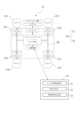
図1は、本実施形態における環境情報分析システム100のシステム構成を示す図である。図2は、飛行体10の構成を示す斜視図である。以下では、環境情報分析システム100を物流に適用する場合について説明する。環境情報分析システム100は、図1に示すように、荷物Lを搭載可能な自立飛行型の飛行体10及びサーバ30がネットワークや無線LAN(移動体通信網を含む)を介して通信接続可能に接続されている。 FIG. 1 is a diagram showing the system configuration of an environmental
<飛行体の構成>
図1及び図2を参照して、上述した飛行体10は、一般に以下のような構成を有している。飛行体10は、フライトコントローラ11、プロペラ12A~12D、モータ13A~13D、アーム14A~14Dなどで構成される。<Configuration of the aircraft>
Referring to FIGS. 1 and 2, the above-described flying
フライトコントローラ11は、プログラマブルプロセッサ(例えば、中央演算処理装置(CPU))などを有することができ、またフライトコントローラ11が実行可能であるロジック・コード・およびプログラム命令を記憶するためのメモリを有しても良い。
メモリは、例えば、SDカードなどの分離可能な媒体または外部の記憶装置を含んでいてもよい。カメラやセンサ類から取得したデータは、メモリに直接に伝達されかつ記憶されてもよい。例えば、カメラ等で撮影した静止画・動画データが内蔵の記憶装置又は外部の記憶装置に記録される。 The memory may include, for example, a separable medium such as an SD card or an external storage device. Data acquired from cameras and sensors may be communicated directly to and stored in memory. For example, still image/video data taken with a camera or the like is recorded in a built-in storage device or an external storage device.
フライトコントローラ11にあるセンサ類は、慣性センサ(加速度センサ、ジャイロセンサ等)、GPSセンサ、地磁気センサ、近接センサ(例えば、LIDAR)、高度センサ、またはビジョンセンサ(例えば、カメラ)を含み得る。 Sensors in
モータ13A~13D・ESC(Electronic Speed Controller)・プロペラ12A~12Dなどの推力発生装置および推力制御装置は、フライトコントローラ11および送受信機からの信号を受けて所望の飛行を実現する。推力発生装置は、電気モータの他にガソリンエンジンなどを用いてもよい。Thrust generators and thrust control devices such as
本発明のプロペラ12A~12Dは、羽根は細長い形状を有している。任意の羽根(回転子)の数(例えば、1、2、3、4、またはそれ以上の羽根)でよい。また、羽根の形状は、平らな形状、曲がった形状、よじれた形状、テーパ形状、またはそれらの組み合わせ等の任意の形状が可能である。 The blades of the
モータ13A~13Dは、プロペラ12A~12Dの回転を生じさせるものである。羽根は、モータ13A~13Dによって駆動可能であり、時計方向に及び/または反時計方向に、モータ13A~13Dの回転軸(例えば、長軸)の周りに回転する。 The
飛行体10は、対応するモータ13A~13D及びプロペラ12A~12Dを支持するアーム14A~14Dを有している。アーム14A~14Dには、飛行体10の飛行状態、飛行方向等を示すためにLED等の発色体を設けることとしてもよい。本実施の形態によるアーム14A~14Dは、カーボン、ステンレス、アルミニウム、マグネシウム等またはこれらの合金又は組合わせ等から適宜選択される素材で形成することが可能である。 The
飛行体10は、必要に応じて搭載部を備えていてもよい。搭載部は、搭載対象物(カメラ、荷物保持部、作業ツール等)を搭載・保持するための機構である。搭載部は、搭載対象物位置及び向きを維持することができるように、常に所定の方向(例えば、水平方向(鉛直下向き))に、その状態を保持する構成としてもよい。 The flying
飛行体10は、バッテリーなどのエネルギー源を備える。電気エネルギーに限らず、ガソリン等の化学エネルギーおよびエネルギー変換モジュールを備えても良い。また、例えば、無線送電のような非接触給電による蓄電モジュールを備えてもよい。The flying
飛行体10は、空中撮影や電波中継など、飛行を実現することに直接には関与しない目的にて備えられたセンサおよび動作機構を有することがある。例えば、カメラセンサ、温度センサ、ジンバル機構、物件の投下機構などがあげられ、飛行体10の任務によってはこれらには限らない。The flying
<サーバの構成>
図1を参照して、上述したサーバ30は、一般に以下のような構成を有している。<Server configuration>
Referring to FIG. 1, the
サーバ30は、センサ情報取得部31、状態分析部32、環境情報生成部33を有する。 The
センサ情報取得部31は、例えば、飛行体10のセンサ類が計測した信号や、モータ13A~13Dの回転数を示す信号を、センサ情報として取得する処理部である。 The sensor
状態分析部32は、センサ情報取得部31が取得したセンサ情報に基づいて、飛行体10の周囲の状態に関する状態情報を分析する。状態情報は、例えば、モータ13A~13Dの回転数に基づいて得られるモータ13A~13Dの負荷であってもよいし、飛行体10のセンサ類が計測した機体の傾きであってもよいし、飛行体10の飛行高度であってもよい。 The
環境情報生成部33は、状態分析部32による状態情報の分析結果に基づいて、飛行体10の周囲における環境情報を生成する。環境情報には、気流の風速・風向が含まれ得る。状態情報と環境情報の関係は、実験等から得られるテーブル情報としてサーバ30に予め格納されている。 The environmental
サーバ30は、荷物Lの配送先の場所に関する場所情報に基づいて、飛行体10に配送先への移動を指示する。配送指示には、場所情報及び配送日時情報が含まれ得る。飛行体10は、配送指示に含まれる各情報をメモリに記録し、場所情報に向けて飛行を開始する。配送対象の荷物Lは、予め配送業者等により飛行体10の搭載部に載せておけばよい。 The
なお、飛行体10が指定された場所に飛行する方法自体は、公知の自動操縦方法で行われるようにすればよい。例えば、飛行体10は、GPSセンサから得られた緯度経度情報を現在地とし、場所情報が示す緯度経度情報を配送先に設定して、予め定められた空域(地上に近い比較的低い高度の上空)を自動飛行してもよい。そして、飛行体10は、現在地から配送先に向けた方向が進行方向となるように、プロペラ12A~12Dの制御を行ってもよい。進行方向は、例えば、センサ類の地磁気センサから得られた方角を利用して決定される。Note that the method for the flying
また、サーバ30から飛行体10に対して、配送先への飛行ルートに関する飛行ルート情報が指示されるようにしてもよい。飛行ルート情報は、配送先に到達するまでの飛行ルートを示す情報であり、例えば、飛行ルートを示すように配送先までの緯度経度情報を順番に繋いだ情報であってよい。サーバ30は、所定の経路検索アルゴリズムに基づいて飛行ルート情報を生成すればよい。なお、飛行ルート情報は、配送指示に含まれていてもよい。飛行体10は、サーバ30から受信した飛行ルート情報に基づいて、配送先への自動操縦制御を実行することになる。Further, the flight route information regarding the flight route to the delivery destination may be instructed from the
飛行ルート情報に基づいて、飛行体10を上昇させる操作が行われると、この操作に応じた制御装置の制御によって、プロペラ12A~12Dの回転数も増加する。これにより、プロペラ12A~12Dは飛行体10の上昇に必要な揚力を徐々に生じさせる。揚力が飛行体10にかかる重力を超えると、飛行体10は空中に浮き始め、矢印A方向に浮上する(図3(A)参照)。When an operation is performed to raise the flying
そして、飛行体10が所望の高度に到着すると、飛行体10が空中停止(ホバリング)するように、プロペラ12A~12Dの回転数が調整される(図3(B)参照)。つまり、このときの回転数は、各プロペラ12A~12Dの回転による揚力と飛行体10にかかる重力とが釣り合う程度の回転数である。 Then, when the flying
次に、自動操縦制御によって飛行体10を水平方向に移動させる場合には、進行方向に向かって後方にあるプロペラ12B、12Cの回転数を、進行方向に向かって前方にあるプロペラ12A、12Dの回転数よりも多くする制御が行われる。これにより、後方にあるプロペラ12B、12Cによる揚力が前方にあるプロペラ12A 、12Dによる揚力に比べて大きくなり、プロペラ12B、12Cの位置がプロペラ12A、12Dの位置よりも高くなる(図3(C)参照)。このような姿勢になると直ちに、各プロペラ12A~12Dの回転数は、所望の速度で水平方向に移動するような回転数に調整される。 Next, when the
飛行体10は、風の影響でバランスが崩れたり墜落したりしないように飛行制御されていればよい。例えば、飛行体10が風に耐え得るように、飛行ルート情報が定義されていてもよい。飛行体10が風に耐え得るとは、例えば、風上側を向くような姿勢を取ること、風上側に向けて飛行体10が移動すること、又は、風上側のプロペラの回転数を風下側のプロペラの回転数よりも少なくすることなどである。 The flight of the flying
例えば、飛行体10の進行方向Bに対して左から右に風が吹いている場合(図4参照)、飛行体10が風に流されることなく所定の位置に留まるように、プロペラ12A~12Dの回転数が調整される。このとき、風上側のプロペラ12B、12Cの回転数が風下側のプロペラ12A、12Dの回転数よりも少なくなるように調整される。環境情報生成部33は、サーバ30に予め格納されているテーブル情報を参照して、モータ13A~13Dの負荷を風向・風速に換算することで、飛行体10の周囲の風向・風速を計測する。 For example, when the wind is blowing from left to right with respect to the traveling direction B of the aircraft 10 (see FIG. 4), the
このような手法により、環境情報生成部33において風向・風速の計測が行われることによって、飛行体1に風速計を配備する必要がない。つまり、既存の飛行体10を利用して風向・風速の計測を行うことができる。従って、簡易な構成で、飛行体10の周囲の環境情報を取得することができる。 By such a method, the wind direction and wind speed are measured in the environmental
(第2の実施の形態)
以下、本発明の第2の実施の形態による環境情報分析方法について、図面を参照しながら説明する。なお、第1の実施の形態に係る環境情報分析方法が適用される飛行体10と、本実施形態に係る環境情報分析方法が適用される飛行体10とは同様のものであるので、説明を省略することがある。(Second embodiment)
An environmental information analysis method according to a second embodiment of the present invention will be described below with reference to the drawings. Note that the
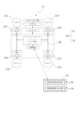
環境情報分析システム200は、図5に示すように、飛行体10及びサーバ30がネットワークや無線LAN(移動体通信網を含む)を介して通信接続可能に接続されている。 In the environmental information analysis system 200, as shown in FIG. 5, the
<飛行体の構成>
飛行体10の制御部は、飛行体10に対して第1の状態から第2の状態に遷移する作用が働いた場合に、第2の状態から第1の状態に復帰させるように飛行体10を復帰制御する機能を有している。第1の状態を示す情報や、第2の情報を示す情報は、飛行体10の空間的配置についての情報、例えば、経度、緯度、高度などのロケーションまたは位置情報や、ロール、ピッチおよび/またはヨーなど向きまたは姿勢情報を含み得る。<Configuration of the aircraft>
The control unit of the
<サーバの構成>
サーバ30は、復帰情報取得部34と、環境情報分析部35とを有する。復帰情報取得部34は、飛行体10の上述した復帰制御に関する復帰情報を飛行体10から取得する。ここでの復帰情報は、例えば、モータ13A~13Dの回転数に基づいて得られるモータ13A~13Dの負荷であってもよいし、飛行体10のセンサ類が計測した機体の傾き・飛行高度であってもよい。環境情報分析部35は、復帰情報取得部34が取得した復帰情報に基づいて、飛行体10の周囲の環境情報を分析する。環境情報には、気流の風速・風向が含まれ得る。復帰情報と環境情報の関係は、実験等から得られるテーブル情報としてサーバ30に予め格納されている。<Server configuration>
The
図6は、飛行体10の状態が遷移する様子の一例を示す平面図である。飛行体10は、図6に示すように、無風状態にある第1時点tにおいて、実線で示す第1の状態aにある。そして、風が吹き始めた第2時点t+1において、飛行体10は、図6に示すように、破線で示す第2の状態bにある。すなわち、第1時点から第2時点に至るまでの間に、飛行体10は、風に耐え得るように、風上側を向くような姿勢を保つべく風上側に向けて移動する。このとき、風上側のプロペラ12A、12Bの回転数が風下側のプロペラ12C、12Dの回転数よりも少なくなるように調整される。 FIG. 6 is a plan view showing an example of how the state of the
そして、環境情報分析部35は、サーバ30に予め格納されているテーブル情報を参照して、モータ13A~13Dの負荷を風向・風速に換算することで、飛行体10の周囲の風向・風速を計測する。Then, the environmental
このような手法により、環境情報分析部35において風向・風速の計測が行われることによって、飛行体1に風速計を配備する必要がない。従って、簡易な構成で、飛行体10の周囲の環境情報を取得することができる。By such a method, wind direction and wind speed are measured in the environmental
以上、飛行体10の姿勢制御機能を利用した風速計は、図7に示されるように、以下の機能としてまとめることができる。即ち、飛行中(進行中又はホバリング中)における飛行体10からは、上述した様々なセンサデバイスによって、飛行体10に加わる負荷(風等)の情報を付加情報として取得することができる。当該付加情報は、風速や気圧などの飛行体10に加わる生の情報(ロウデータ)であってもいいし、分析可能に処理を行うための何らかの前処理が行われるていてもよい。当該付加情報は、制御部に入力される。制御部は、当該付加情報に基づいて、飛行体10が安全に飛行可能となるように、制御情報を生成する(姿勢制御を行うためのあらゆる情報等)制御情報は、飛行体10の飛行を可能にするための各部位(モータ等)の制御に用いられる。
かかる構成を前提とすると、本実施の形態による風速計は、付加情報を利用して環境情報(風速情報等)を生成(推定)する場合と、制御部によって生成され制御情報を利用して環境情報を生成(推定)する場合と、これらを両方利用する場合との3タイプに分けることが可能である。上述した実施の形態は、いずれも、この3パターンを利用した場合について採用することが可能である。As described above, the anemometer that utilizes the attitude control function of the
Assuming such a configuration, the anemometer according to the present embodiment can generate (estimate) environmental information (wind speed information, etc.) using additional information, and can generate (estimate) environmental information (wind speed information, etc.) using control information generated by the control unit. It can be divided into three types: a case where information is generated (estimated) and a case where both of these are used. Any of the embodiments described above can be adopted in cases where these three patterns are used.
本発明は、次のような把握の仕方をすることもできる。即ち、本発明は、制御部を備える飛行体を利用して当該飛行体の周囲における環境情報を分析する環境情報分析方法である。制御部は、飛行体に対して第1の状態(初期状態)から第2の状態(風などの外力を受けた場合に当該外力に従って変位する位置/変位したであろう位置)に遷移する作用が働いた場合に、第2の状態から前記第1の状態に復帰させるように当該飛行体を復帰制御する機能を有している。管理サーバは、飛行体を経由して復帰制御に関する復帰情報を取得し、当該復帰情報に基づいて飛行体の周囲の環境情報を分析する。 The present invention can also be understood in the following way. That is, the present invention is an environmental information analysis method for analyzing environmental information around an aircraft using an aircraft equipped with a control unit. The control unit has an action that causes the aircraft to transition from a first state (initial state) to a second state (position to which it would be displaced/position to which it would have been displaced if it received an external force such as wind). It has a function of returning the aircraft from the second state to the first state when the aircraft is activated. The management server acquires return information related to return control via the aircraft, and analyzes environmental information around the aircraft based on the return information.
上述した実施の形態は、本発明の理解を容易にするための例示に過ぎず、本発明を限定して解釈するためのものではない。本発明は、その趣旨を逸脱することなく、変更、改良することができると共に、本発明にはその均等物が含まれることは言うまでもない。 The embodiments described above are merely illustrative to facilitate understanding of the present invention, and are not intended to be interpreted as limiting the present invention. It goes without saying that the present invention can be modified and improved without departing from its spirit, and that the present invention includes equivalents thereof.
[変形例] 上記の実施形態を次のように変形してもよい。
環境情報生成部33又は環境情報分析部35は、駆動モータ13A~13Dの回転数を示す信号に対して高速フーリエ変換(FFT)を行い、信号の周波数スペクトラムから、飛行体10の周囲の風向・風速の情報を生成してもよい。これにより、時々刻々と変化する飛行体10の周囲の環境について、各環境において適切な周波数スペクトラムを得ることができ、飛行体10の周囲の環境を正確に分析することができる。[Modification] The above embodiment may be modified as follows.
The environmental
また、複数の飛行体10を用いることにより、相互のデータを比較してもよい。さらに、複数の飛行体10を用いることにより、同じ飛行ルートを同じ高度で複数回の情報収集飛行が可能となり、時々刻々と変化する状況について、より高い精度の情報収集が可能となる。 Further, by using a plurality of flying
10 飛行体
12A~12D プロペラ
13A~13D モータ
30 サーバ
31 センサ情報取得部
32 状態分析部
33 環境情報生成部
34 復帰情報取得部
35 環境情報分析部
100、200 環境情報分析システム
10
Claims (3)
Translated fromJapanese前記各モータの相対的な負荷情報に基づいて、前記飛行体の周囲における風速及び風向の少なくともいずれかを含む環境情報を生成する環境情報生成ステップと、
を情報処理装置により実行する環境情報分析方法であって、
前記負荷情報は、各モータの回転数に関する情報に基づいて得られ、
前記環境情報生成ステップは、前記回転数に関する情報に対して高速フーリエ変換を行い、当該高速フーリエ変換により得られた周波数スペクトラムに基づき、前記環境情報を生成する、環境情報分析方法。an information acquisition step of acquiringload information regarding each of the motors from an aircraft having a plurality of motors each having a propeller;
an environmental information generation step of generating environmental information including at least one of wind speed and wind direction around the flying object based on relativeload information ofeach motor;
An environmental information analysis method performed by an information processing device, the method comprising:
The load information is obtained based on information regarding the rotation speed of each motor,
In the environmental information analysis method, the environmental information generating step performs fast Fourier transform on the information regarding the rotation speed, and generates the environmental information based on the frequency spectrum obtained by the fast Fourier transform.
前記各モータの相対的な負荷情報に基づいて、前記飛行体の周囲における風速及び風向の少なくともいずれかを含む環境情報を生成する環境情報生成ステップと、
を情報処理装置に実行させるプログラムであって、
前記負荷情報は、各モータの回転数に関する情報に基づいて得られ、
前記環境情報生成ステップは、前記回転数に関する情報に対して高速フーリエ変換を行い、当該高速フーリエ変換により得られた周波数スペクトラムに基づき、前記環境情報を生成する、プログラム。an information acquisition step of acquiringload information regarding each of the motors from an aircraft having a plurality of motors each having a propeller;
an environmental information generation step of generating environmental information including at least one of wind speed and wind direction around the flying object based on relativeload information ofeach motor;
A programthat causes an information processing device to execute,
The load information is obtained based on information regarding the rotation speed of each motor,
The environmental information generating step is a program that performs fast Fourier transform on the information regarding the rotation speed and generates the environmental information based on the frequency spectrum obtained by the fast Fourier transform.
前記各モータの相対的な負荷情報に基づいて、前記飛行体の周囲における風速及び風向の少なくともいずれかを含む環境情報を生成する環境情報生成部と、
を備え、
前記負荷情報は、各モータの回転数に関する情報に基づいて得られ、
前記環境情報生成部は、前記回転数に関する情報に対して高速フーリエ変換を行い、当該高速フーリエ変換により得られた周波数スペクトラムに基づき、前記環境情報を生成する、情報処理装置。
an information acquisition unit that acquiresload information regarding each of the motors from an aircraft having a plurality of motors each having a propeller;
an environmental information generation unit that generates environmental information including at least one of wind speed and wind direction around the flying object based on relativeload information ofeach motor;
Equipped with
The load information is obtained based on information regarding the rotation speed of each motor,
The environment information generation unit is an information processing device that performs fast Fourier transform on the information regarding the rotation speed and generates the environment information based on a frequency spectrum obtained by the fast Fourier transform.
Applications Claiming Priority (1)
| Application Number | Priority Date | Filing Date | Title |
|---|---|---|---|
| PCT/JP2019/027843WO2021009826A1 (en) | 2019-07-16 | 2019-07-16 | Environment information analysis method |
Publications (3)
| Publication Number | Publication Date |
|---|---|
| JPWO2021009826A1 JPWO2021009826A1 (en) | 2021-01-21 |
| JPWO2021009826A5 JPWO2021009826A5 (en) | 2022-07-21 |
| JP7368840B2true JP7368840B2 (en) | 2023-10-25 |
Family
ID=74210346
Family Applications (1)
| Application Number | Title | Priority Date | Filing Date |
|---|---|---|---|
| JP2019547527AActiveJP7368840B2 (en) | 2019-07-16 | 2019-07-16 | Environmental information analysis method |
Country Status (2)
| Country | Link |
|---|---|
| JP (1) | JP7368840B2 (en) |
| WO (1) | WO2021009826A1 (en) |
Families Citing this family (1)
| Publication number | Priority date | Publication date | Assignee | Title |
|---|---|---|---|---|
| JP2023068391A (en)* | 2021-11-02 | 2023-05-17 | 株式会社ロボデックス | Unmanned Aircraft Control Device, Unmanned Aircraft Control Method, Unmanned Aircraft Control Program, and Unmanned Aircraft |
Citations (6)
| Publication number | Priority date | Publication date | Assignee | Title |
|---|---|---|---|---|
| JP2012083318A (en) | 2010-10-14 | 2012-04-26 | Institute Of National Colleges Of Technology Japan | Weather observation device |
| US20160018822A1 (en) | 2014-07-18 | 2016-01-21 | Helico Aerospace Industries Sia | Autonomous vehicle operation |
| JP2017501475A (en) | 2014-09-05 | 2017-01-12 | エスゼット ディージェイアイ テクノロジー カンパニー リミテッドSz Dji Technology Co.,Ltd | Flight mode selection based on situation |
| CN107860940A (en) | 2017-11-02 | 2018-03-30 | 四川联众防务科技有限责任公司 | A kind of wind speed forecasting method based on unmanned plane big data |
| KR101844727B1 (en) | 2017-12-11 | 2018-04-02 | 세종대학교산학협력단 | System for estimating wind information using rotor type unmanned areial vehicle |
| WO2018065096A1 (en) | 2016-10-07 | 2018-04-12 | Cavos Bagatelle Verwaltungs Gmbh & Co. Kg | Wind measurement by means of a multicopter |
Family Cites Families (1)
| Publication number | Priority date | Publication date | Assignee | Title |
|---|---|---|---|---|
| JPH04262997A (en)* | 1991-02-18 | 1992-09-18 | Mitsubishi Heavy Ind Ltd | Simplified airspeed detector |
- 2019
- 2019-07-16JPJP2019547527Apatent/JP7368840B2/enactiveActive
- 2019-07-16WOPCT/JP2019/027843patent/WO2021009826A1/ennot_activeCeased
Patent Citations (6)
| Publication number | Priority date | Publication date | Assignee | Title |
|---|---|---|---|---|
| JP2012083318A (en) | 2010-10-14 | 2012-04-26 | Institute Of National Colleges Of Technology Japan | Weather observation device |
| US20160018822A1 (en) | 2014-07-18 | 2016-01-21 | Helico Aerospace Industries Sia | Autonomous vehicle operation |
| JP2017501475A (en) | 2014-09-05 | 2017-01-12 | エスゼット ディージェイアイ テクノロジー カンパニー リミテッドSz Dji Technology Co.,Ltd | Flight mode selection based on situation |
| WO2018065096A1 (en) | 2016-10-07 | 2018-04-12 | Cavos Bagatelle Verwaltungs Gmbh & Co. Kg | Wind measurement by means of a multicopter |
| CN107860940A (en) | 2017-11-02 | 2018-03-30 | 四川联众防务科技有限责任公司 | A kind of wind speed forecasting method based on unmanned plane big data |
| KR101844727B1 (en) | 2017-12-11 | 2018-04-02 | 세종대학교산학협력단 | System for estimating wind information using rotor type unmanned areial vehicle |
Also Published As
| Publication number | Publication date |
|---|---|
| JPWO2021009826A1 (en) | 2021-01-21 |
| WO2021009826A1 (en) | 2021-01-21 |
Similar Documents
| Publication | Publication Date | Title |
|---|---|---|
| US12351296B2 (en) | Adaptive thrust vector unmanned aerial vehicle | |
| JP6585673B2 (en) | Aircraft attitude control method | |
| JP6308642B1 (en) | Flying object | |
| JP6207746B2 (en) | Aircraft attitude control method and apparatus | |
| CN107434034A (en) | With vertical takeoff and landing(VTOL)The unmanned vehicle of function(UAV) | |
| JP6384013B1 (en) | Flying object | |
| US11639221B2 (en) | Flying vehicle and flying method therefor | |
| JP2018203226A (en) | Flight vehicle | |
| CN112638770A (en) | Safe unmanned aerial vehicle | |
| US12377977B2 (en) | Manned aircraft | |
| JP6664820B1 (en) | Flying object | |
| CN118239026A (en) | Rotor unit, stacked rotor blade and manufacturing method | |
| US20200354047A1 (en) | Rotorcraft | |
| WO2021059322A1 (en) | Aerial vehicle | |
| JP7368840B2 (en) | Environmental information analysis method | |
| US20230013275A1 (en) | Takeoff and landing system | |
| JP2019182390A (en) | Flight body | |
| JP6993711B2 (en) | Flying objects and flying methods of flying objects | |
| JP7006930B2 (en) | Rotorcraft | |
| JP6664821B2 (en) | Flying object | |
| JP6671705B2 (en) | Flying object | |
| WO2021053829A1 (en) | Flying body | |
| JP7711909B2 (en) | Aircraft | |
| JP7539683B2 (en) | Aircraft | |
| JP6767070B2 (en) | Aircraft |
Legal Events
| Date | Code | Title | Description |
|---|---|---|---|
| A521 | Request for written amendment filed | Free format text:JAPANESE INTERMEDIATE CODE: A523 Effective date:20220712 | |
| A621 | Written request for application examination | Free format text:JAPANESE INTERMEDIATE CODE: A621 Effective date:20220712 | |
| A131 | Notification of reasons for refusal | Free format text:JAPANESE INTERMEDIATE CODE: A131 Effective date:20230202 | |
| A521 | Request for written amendment filed | Free format text:JAPANESE INTERMEDIATE CODE: A523 Effective date:20230329 | |
| A131 | Notification of reasons for refusal | Free format text:JAPANESE INTERMEDIATE CODE: A131 Effective date:20230525 | |
| A521 | Request for written amendment filed | Free format text:JAPANESE INTERMEDIATE CODE: A523 Effective date:20230724 | |
| TRDD | Decision of grant or rejection written | ||
| A01 | Written decision to grant a patent or to grant a registration (utility model) | Free format text:JAPANESE INTERMEDIATE CODE: A01 Effective date:20230914 | |
| A61 | First payment of annual fees (during grant procedure) | Free format text:JAPANESE INTERMEDIATE CODE: A61 Effective date:20231005 | |
| R150 | Certificate of patent or registration of utility model | Ref document number:7368840 Country of ref document:JP Free format text:JAPANESE INTERMEDIATE CODE: R150 |