JP7366360B2 - Blood vessel identification device and blood vessel identification method - Google Patents
Blood vessel identification device and blood vessel identification methodDownload PDFInfo
- Publication number
- JP7366360B2 JP7366360B2JP2019091843AJP2019091843AJP7366360B2JP 7366360 B2JP7366360 B2JP 7366360B2JP 2019091843 AJP2019091843 AJP 2019091843AJP 2019091843 AJP2019091843 AJP 2019091843AJP 7366360 B2JP7366360 B2JP 7366360B2
- Authority
- JP
- Japan
- Prior art keywords
- blood vessel
- matching
- blood
- target region
- parameters
- Prior art date
- Legal status (The legal status is an assumption and is not a legal conclusion. Google has not performed a legal analysis and makes no representation as to the accuracy of the status listed.)
- Active
Links
Images


Classifications
- A—HUMAN NECESSITIES
- A61—MEDICAL OR VETERINARY SCIENCE; HYGIENE
- A61M—DEVICES FOR INTRODUCING MEDIA INTO, OR ONTO, THE BODY; DEVICES FOR TRANSDUCING BODY MEDIA OR FOR TAKING MEDIA FROM THE BODY; DEVICES FOR PRODUCING OR ENDING SLEEP OR STUPOR
- A61M5/00—Devices for bringing media into the body in a subcutaneous, intra-vascular or intramuscular way; Accessories therefor, e.g. filling or cleaning devices, arm-rests
- A61M5/42—Devices for bringing media into the body in a subcutaneous, intra-vascular or intramuscular way; Accessories therefor, e.g. filling or cleaning devices, arm-rests having means for desensitising skin, for protruding skin to facilitate piercing, or for locating point where body is to be pierced
- A61M5/427—Locating point where body is to be pierced, e.g. vein location means using ultrasonic waves, injection site templates
- G—PHYSICS
- G06—COMPUTING OR CALCULATING; COUNTING
- G06T—IMAGE DATA PROCESSING OR GENERATION, IN GENERAL
- G06T7/00—Image analysis
- G06T7/0002—Inspection of images, e.g. flaw detection
- G06T7/0012—Biomedical image inspection
- A—HUMAN NECESSITIES
- A61—MEDICAL OR VETERINARY SCIENCE; HYGIENE
- A61B—DIAGNOSIS; SURGERY; IDENTIFICATION
- A61B10/00—Instruments for taking body samples for diagnostic purposes; Other methods or instruments for diagnosis, e.g. for vaccination diagnosis, sex determination or ovulation-period determination; Throat striking implements
- A—HUMAN NECESSITIES
- A61—MEDICAL OR VETERINARY SCIENCE; HYGIENE
- A61B—DIAGNOSIS; SURGERY; IDENTIFICATION
- A61B5/00—Measuring for diagnostic purposes; Identification of persons
- A61B5/103—Measuring devices for testing the shape, pattern, colour, size or movement of the body or parts thereof, for diagnostic purposes
- A61B5/107—Measuring physical dimensions, e.g. size of the entire body or parts thereof
- A—HUMAN NECESSITIES
- A61—MEDICAL OR VETERINARY SCIENCE; HYGIENE
- A61M—DEVICES FOR INTRODUCING MEDIA INTO, OR ONTO, THE BODY; DEVICES FOR TRANSDUCING BODY MEDIA OR FOR TAKING MEDIA FROM THE BODY; DEVICES FOR PRODUCING OR ENDING SLEEP OR STUPOR
- A61M2205/00—General characteristics of the apparatus
- A61M2205/33—Controlling, regulating or measuring
- A61M2205/3306—Optical measuring means
- A61M2205/3313—Optical measuring means used specific wavelengths
- A—HUMAN NECESSITIES
- A61—MEDICAL OR VETERINARY SCIENCE; HYGIENE
- A61M—DEVICES FOR INTRODUCING MEDIA INTO, OR ONTO, THE BODY; DEVICES FOR TRANSDUCING BODY MEDIA OR FOR TAKING MEDIA FROM THE BODY; DEVICES FOR PRODUCING OR ENDING SLEEP OR STUPOR
- A61M2205/00—General characteristics of the apparatus
- A61M2205/50—General characteristics of the apparatus with microprocessors or computers
- A61M2205/502—User interfaces, e.g. screens or keyboards
- G—PHYSICS
- G06—COMPUTING OR CALCULATING; COUNTING
- G06T—IMAGE DATA PROCESSING OR GENERATION, IN GENERAL
- G06T2207/00—Indexing scheme for image analysis or image enhancement
- G06T2207/10—Image acquisition modality
- G06T2207/10048—Infrared image
- G—PHYSICS
- G06—COMPUTING OR CALCULATING; COUNTING
- G06T—IMAGE DATA PROCESSING OR GENERATION, IN GENERAL
- G06T2207/00—Indexing scheme for image analysis or image enhancement
- G06T2207/30—Subject of image; Context of image processing
- G06T2207/30004—Biomedical image processing
- G06T2207/30101—Blood vessel; Artery; Vein; Vascular
Landscapes
- Health & Medical Sciences (AREA)
- Engineering & Computer Science (AREA)
- Life Sciences & Earth Sciences (AREA)
- General Health & Medical Sciences (AREA)
- Medical Informatics (AREA)
- Physics & Mathematics (AREA)
- Animal Behavior & Ethology (AREA)
- Veterinary Medicine (AREA)
- Biomedical Technology (AREA)
- Heart & Thoracic Surgery (AREA)
- Public Health (AREA)
- Vascular Medicine (AREA)
- Quality & Reliability (AREA)
- Computer Vision & Pattern Recognition (AREA)
- General Physics & Mathematics (AREA)
- Theoretical Computer Science (AREA)
- Radiology & Medical Imaging (AREA)
- Nuclear Medicine, Radiotherapy & Molecular Imaging (AREA)
- Pathology (AREA)
- Surgery (AREA)
- Molecular Biology (AREA)
- Dermatology (AREA)
- Anesthesiology (AREA)
- Hematology (AREA)
- Oral & Maxillofacial Surgery (AREA)
- Biophysics (AREA)
- Dentistry (AREA)
- Apparatus For Radiation Diagnosis (AREA)
- Measurement Of The Respiration, Hearing Ability, Form, And Blood Characteristics Of Living Organisms (AREA)
- Image Analysis (AREA)
- Infusion, Injection, And Reservoir Apparatuses (AREA)
- Ultra Sonic Daignosis Equipment (AREA)
- Investigating Or Analysing Biological Materials (AREA)
- Prostheses (AREA)
Description
Translated fromJapanese本発明は、血管を特定する血管特定装置及び血管特定方法に関する。 The present invention relates to a blood vessel identification device and a blood vessel identification method for identifying blood vessels.
人体などの一部を撮影した画像から得られた血管の位置を表示するシステムが開発されている(特許文献1、2参照。)。例えば、近赤外線を吸収するヘモグロビンの性質を利用して、近赤外線を照射した部分を赤外線カメラで撮影して血管を可視化する方法が用いられている。 A system has been developed that displays the position of a blood vessel obtained from an image of a part of a human body or the like (see
しかしながら、血管を可視化するだけでなく特定の目的に適合する血管を特定する有効な技術が開発されていない。例えば、採血するために針の穿刺に適した血管を表示する方法などが望まれている。 However, an effective technique that not only visualizes blood vessels but also identifies blood vessels suitable for a specific purpose has not been developed. For example, a method of displaying blood vessels suitable for puncturing with a needle to collect blood is desired.
上記問題点に鑑み、本発明は、特定の目的に適合する血管を特定することができる血管特定装置及び血管特定方法を提供することを目的とする。 In view of the above problems, an object of the present invention is to provide a blood vessel identification device and a blood vessel identification method that can identify blood vessels suitable for a specific purpose.
本発明の一態様によれば、対象部位の解析用画像を画像処理して、対象部位に含まれる複数の血管の位置及び形状を含む血管情報を取得する画像処理装置と、血管情報を用いて、解析用画像に含まれる複数の血管それぞれに関して血管に針の穿刺しやすさという目的に対する適合性を示す複数のパラメータについて、適合の程度に応じて点数化する評価装置と、複数のパラメータの合計点数に基づき、対象部位に含まれる複数の血管の中から目的に適合する適合血管を特定する特定装置とを備え、評価装置が、血管の延伸方向および解析用画像の特定地点からの距離の少なくともいずれかをパラメータの1つとして点数化する血管特定装置が提供される。According to one aspect of the present invention, an image processing device that performs image processing on an analysis image of a target region to obtain blood vessel information including the positions and shapes ofa plurality of blood vessels included in the target region; , an evaluation device that scoresa plurality of parameters according to the degree of suitability foreach ofa plurality of blood vessels included in an analysis image to indicate suitability for the purposeof ease of puncturing the blood vessel with a needle , and atotalof the plurality of parameters. an identification device that identifies a suitable blood vessel suitable for the purpose from amonga plurality of blood vessels included in the targetregion based on the score; A blood vessel identifying device is providedthat scores any of the parameters as one of the parameters .
本発明の他の態様によれば、対象部位の解析用画像を画像処理して、対象部位に含まれる複数の血管の位置及び形状を含む血管情報を取得するステップと、血管情報を用いて、解析用画像に含まれる複数の血管それぞれに関して血管に針の穿刺しやすさという目的に対する適合性を示す複数のパラメータについて、適合の程度に応じて点数化するステップと、複数のパラメータの合計点数に基づき、対象部位に含まれる複数の血管の中から目的に適合する適合血管を特定するステップとを含み、血管の延伸方向および解析用画像の特定地点からの距離の少なくともいずれかをパラメータの1つとして点数化する血管特定方法が提供される。According to another aspect of the present invention, a step of performing image processing on an analysis image of a target region to obtain blood vessel information including the positions and shapes ofa plurality of blood vessels included in the target region, and using the blood vessel information, A step of scoringa plurality of parameters according to the degree of conformity foreach ofthe plurality of blood vessels included in the analysis image, which indicates suitability for the objectiveof making it easier to puncture the blood vessel with a needle , and calculating atotal score ofthe plurality of parameters. and identifying a blood vessel suitable for the purpose from amonga plurality of blood vessels included in the target region based on the target region, and at least one of the extending direction of the blood vessel and the distance from the specific point of the analysis image is set as one of the parameters. A blood vessel identification method is providedthat scores the blood vessel as one point .
本発明によれば、特定の目的に適合する血管を特定することができる血管特定装置及び血管特定方法を提供できる。 According to the present invention, it is possible to provide a blood vessel identification device and a blood vessel identification method that can identify a blood vessel suitable for a specific purpose.
図面を参照して、本発明の実施形態を説明する。以下の図面の記載において、同一又は類似の部分には同一又は類似の符号を付している。ただし、図面は模式的なものであることに留意すべきである。また、以下に示す実施形態は、この発明の技術的思想を具体化するための装置や方法を例示するものであって、この発明の実施形態は、構成部品の構造、配置などを下記のものに特定するものでない。この発明の実施形態は、特許請求の範囲において、種々の変更を加えることができる。 Embodiments of the present invention will be described with reference to the drawings. In the description of the drawings below, the same or similar parts are designated by the same or similar symbols. However, it should be noted that the drawings are schematic. In addition, the embodiments shown below exemplify devices and methods for embodying the technical idea of this invention, and the embodiments of this invention have the structure, arrangement, etc. of component parts as follows. It is not specific to The embodiments of this invention can be modified in various ways within the scope of the claims.
(第1の実施形態)
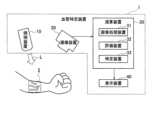
本発明の第1の実施形態に係る血管特定装置は、被検体の対象部位に含まれる血管の中から、所定の目的に適合する血管を特定する。以下では、図1に示すように、人体の前腕の一部が対象部位2である場合について例示的に説明する。図1に示す血管特定装置1は、照明装置10、撮像装置20、演算装置30及び表示装置40を備える。演算装置30は、画像処理装置31、評価装置32及び特定装置33を有する。(First embodiment)
The blood vessel identifying device according to the first embodiment of the present invention identifies blood vessels that are suitable for a predetermined purpose from among blood vessels included in a target region of a subject. Below, as shown in FIG. 1, a case where a part of the forearm of a human body is the
照明装置10は、対象部位2に特定の波長の照射光Lを照射する。撮像装置20は、血管周辺の領域を含む対象部位2を撮影して、対象部位2の解析用画像を取得する。演算装置30は、解析用画像に基づき、対象部位2に含まれる血管の中から目的に適合する血管を特定する。特定された血管の情報は、表示装置40に表示される。以下に、血管特定装置1の詳細について説明する。 The
照明装置10から照射される照射光Lの波長は、照射光Lが対象部位2に照射されることにより、照射光Lが照射されない場合よりも血管と他の領域との境界が明確である解析用画像が撮像装置20によって取得されるように選択される。例えば、近赤外線を吸収するヘモグロビンの性質を利用して、照射光Lとして波長が800nm~900nm程度の近赤外線を使用してもよい。近赤外線を照射光Lに使用した場合、撮像装置20には赤外線カメラが好適に使用される。その結果、血管が黒く写り、皮膚などのその他の部分が白く写った解析用画像が得られる。 The wavelength of the irradiation light L emitted from the
ただし、照射光Lが照射されていない場合でも血管と他の領域との境界が明確である解析用画像を取得できる場合には、解析用画像を取得する際に対象部位2に照射光Lを照射することは必ずしも必要でない。 However, if it is possible to obtain an analysis image in which the boundary between blood vessels and other areas is clear even when the irradiation light L is not irradiated, the irradiation light L is applied to the
撮像装置20によって取得された対象部位2の解析用画像は、画像処理装置31に送信される。画像処理装置31は、解析用画像を画像処理して、対象部位2に含まれる血管の位置及び形状を含む血管情報を取得する。 The image for analysis of the
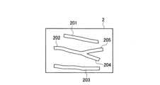
図2に、対象部位2に含まれる血管の例を示す。図2に示した例では、血管201~205の血管情報が取得される。なお、血管に分岐がある場合には、画像処理装置31は、分岐する位置から解析用画像で確認できる端部までを一つの血管として、血管情報を取得する。つまり、分岐する位置から個々の端部までを一つの血管とし、それぞれの血管の血管情報が取得される。 FIG. 2 shows an example of blood vessels included in the
画像処理装置31は、例えば、皮膚などの血管以外の部位と血管との輝度の差に基づいて解析用画像の二値化を行って血管をその他の領域と区別し、血管情報を取得する。このとき、解析用画像について、血管と血管以外の部位とでコントラストをつける画像処理をしてから、解析用画像の二値化を行ってもよい。 The
評価装置32は、画像処理装置31により得られた血管情報を用いて、解析用画像に含まれる血管に関して特定の目的に対する適合性を示すパラメータについて、適合の程度に応じて点数化する。例えば、適合する程度が高いほどパラメータの点数を高くする。特定装置33は、パラメータの点数に基づき、対象部位2に含まれる血管の中から目的に適合する血管を特定する。 The
点数化するパラメータは、血管を特定する目的に応じて選択される。例えば、針を穿刺しやすい血管を特定する目的の場合には、針の穿刺しやすさを示すパラメータが選択される。この場合に選択されるパラメータは、例えば、血管の直進性、血管の延伸方向、血管の長さ、血管の太さなどである。これは、以下の理由による。 The parameters to be scored are selected depending on the purpose of identifying blood vessels. For example, if the purpose is to identify a blood vessel that is easy to puncture with a needle, a parameter indicating ease of puncturing with a needle is selected. The parameters selected in this case include, for example, the straightness of the blood vessel, the direction in which the blood vessel extends, the length of the blood vessel, and the thickness of the blood vessel. This is due to the following reasons.
即ち、血管の直進性が低いほど、針を血管に穿刺することが難しい。したがって、血管の直進性が高いほど好ましい。また、血管の部位によっては、特定の方向からの方が、他の方向からよりも針を穿刺しやすい場合がある。例えば、前腕に穿刺する場合には、手首から肘に向けた方向が穿刺しやすい方向であることが多い。このように、血管の延伸方向について好ましい特定の方向(以下において「適合方向」という。)が存在する場合がある。また、血管が短いほど穿刺が難しい。一方、血管が太いほど穿刺することが容易である。 That is, the lower the straightness of the blood vessel, the more difficult it is to puncture the blood vessel with a needle. Therefore, the higher the straightness of the blood vessel, the more preferable it is. Furthermore, depending on the location of the blood vessel, it may be easier to puncture the needle from a specific direction than from other directions. For example, when puncturing the forearm, the direction from the wrist toward the elbow is often the easiest direction to puncture. In this way, there may be a specific direction (hereinafter referred to as a "compatible direction") that is preferable for the direction in which the blood vessel extends. Also, the shorter the blood vessel, the more difficult it is to puncture. On the other hand, the thicker the blood vessel, the easier it is to puncture it.
また、対象部位2の特定地点から離れた箇所に針を穿刺したい場合に、解析用画像の特定地点からの距離を、点数化するパラメータの1つに使用してもよい。これにより、穿刺が困難な位置や穿刺を回避したい位置から離れた血管を特定することができる。 Furthermore, when it is desired to puncture the
評価装置32は、目的に適合しやすいと評価される血管ほど、パラメータの点数を高くする。例えば、針の穿刺しやすさを示すパラメータに関して、血管の直進性のパラメータの点数を高くする。また、血管の延伸方向が適合方向に近い血管ほど、血管の延伸方向のパラメータの点数を高くしてもよい。そして、血管が長いほど血管の長さのパラメータの点数を高くし、血管が太いほど血管の太さのパラメータの点数を高くする。更に、解析用画像の特定地点からの距離が遠い血管ほど、特定地点からの距離のパラメータの点数を高くする。 The
なお、パラメータの点数化には種々の方法が採用可能である。例えば、それぞれのパラメータについて、最も目的に適合する血管の点数を最高点とし、その他の血管の点数を、その最高点よりも低くするようにしてもよい。例えば、血管の太さのパラメータの点数化において、最も太い血管の点数をN点とし、次に太い血管の点数をN-1点とする(N:2以上の整数)。 Note that various methods can be adopted for scoring the parameters. For example, for each parameter, the score of the blood vessel that best suits the purpose may be set as the highest score, and the scores of other blood vessels may be set lower than the highest score. For example, in scoring the parameter of blood vessel thickness, the score of the thickest blood vessel is set to N points, and the score of the next thickest blood vessel is set to N-1 points (N: an integer of 2 or more).
また、他の点数化法としては、最も太い血管の点数をN点とし、他の血管の太さを最も太い血管の太さとの比r(0<r≦1)を用いて、Nr点とする方法を用いてもよい。例えば、血管の太さの比が1:0.98:0.97:0.95である場合に、それぞれの血管の太さのパラメータの点数を1点、0.98点、0.97点、0.95点とする。これにより、単に血管の太さの順序だけで点数化するのではなく、血管の相対的な差として点数化できる。 In addition, another scoring method is to take the point of the thickest blood vessel as N point, and use the ratio r (0<r≦1) of the thickness of the other blood vessels to the thickness of the largest blood vessel to obtain Nr point. You may also use the method of For example, if the ratio of blood vessel thickness is 1:0.98:0.97:0.95, the points for each blood vessel thickness parameter are 1 point, 0.98 point, and 0.97 point. , 0.95 points. As a result, it is possible to score not only the order of the blood vessel thickness, but also the relative difference between the blood vessels.
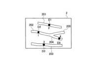
血管の直進性の評価については、評価装置32は、図3に示すように血管201~205のそれぞれについて近似線C1~C5を作成する。例えば、評価装置32は、二値化した解析用画像の血管201~205を細線化により幅を1ピクセルにして、最小二乗法などを用いて近似線C1~C5を作成する。そして、評価装置32は、近似線C1~C5のそれぞれについて得られる決定係数(R2)が1に近い血管ほど直進性が高いと評価して、血管の直進性のパラメータの点数を高くする。For evaluating the straightness of blood vessels, the
血管の延伸方向は、上記の近似線を用いて特定することができる。評価装置32は、近似線の延伸方向と適合方向とのなす角度が小さい血管ほど、血管の延伸方向のパラメータの点数を高くする。なお、適合方向と解析用画像の水平方向が平行になるように解析用画像を撮像し、血管の延伸方向を特定してもよい。 The extending direction of the blood vessel can be specified using the above approximate line. The
血管の長さは、血管の解析用画像に表れる一方の端部から他方の端部までの距離とする。例えば、血管について幅が1ピクセルの近似線を作成し、近似線のピクセル数を血管の長さとしてもよい。血管の太さは、例えば、血管について作成した近似線を利用して算出してもよい。即ち、近似線から周囲に垂線を引き、この垂線と血管の重なった部分の長さを血管の太さとする。血管の太さが変化する場合は、例えば、最も太い部分をその血管の太さとする。 The length of a blood vessel is defined as the distance from one end to the other end that appears in the analysis image of the blood vessel. For example, an approximation line with a width of 1 pixel may be created for the blood vessel, and the number of pixels of the approximation line may be set as the length of the blood vessel. The thickness of the blood vessel may be calculated using, for example, an approximation line created for the blood vessel. That is, a perpendicular line is drawn around the approximation line, and the length of the portion where this perpendicular line overlaps the blood vessel is defined as the thickness of the blood vessel. When the thickness of a blood vessel changes, for example, the thickest part is determined as the thickness of the blood vessel.
解析用画像の特定地点からの距離をパラメータに使用する場合には、図3に示すように、解析用画像に特定地点Tを定義する。そして、特定地点Tから血管までの最短距離が長いほど、特定地点からの距離のパラメータの点数を高くする。 When using the distance from a specific point in the analysis image as a parameter, as shown in FIG. 3, a specific point T is defined in the analysis image. The longer the shortest distance from the specific point T to the blood vessel, the higher the score of the distance parameter from the specific point.
以下に、図2に示した血管201~205から針を穿刺しやすい血管を特定するために、評価装置32が血管に針の穿刺しやすさを示すパラメータについて点数化する例を説明する。ここで、血管の直進性を第1パラメータP1、血管の延伸方向を第2パラメータP2、血管の長さを第3パラメータP3、血管の太さを第4パラメータP4、解析用画像の特定地点からの距離を第5パラメータP5とする。 Below, an example will be described in which the
特定装置33は、評価装置32により点数化されたパラメータを用いて、例えば以下の式(1)を用いて血管を点数化する:
S=P1+P2+P3+P4+P5 ・・・(1)
式(1)から、第1パラメータP1が3点、第2パラメータP2が5点、第3パラメータP3が4点、第4パラメータP4が1点、第5パラメータP5が2点の場合、その血管の合計点Sは15点である。The
S=P1+P2+P3+P4+P5...(1)
From equation (1), if the first parameter P1 is 3 points, the second parameter P2 is 5 points, the third parameter P3 is 4 points, the fourth parameter P4 is 1 point, and the fifth parameter P5 is 2 points, the blood vessel The total score S is 15 points.
なお、血管を特定する目的に応じて、パラメータに重み付けをおこなってもよい。つまり、特定装置33が、目的に適合する血管の特定において影響の大きいパラメータの点数を重要視した合計点Sを算出するようにしてもよい。例えば、以下の式(2)を用いて合計点Sが算出される:
S=a1×P1+a2×P2+a3×P3+a4×P4+a5×P5 ・・・(2)
式(2)で、第1重み付け値a1~第5重み付け値a5は、第1パラメータP1~第5パラメータP5のそれぞれの重要度に応じて設定される。Note that the parameters may be weighted depending on the purpose of identifying blood vessels. In other words, the
S=a1×P1+a2×P2+a3×P3+a4×P4+a5×P5...(2)
In equation (2), the first weighting value a1 to the fifth weighting value a5 are set according to the importance of the first parameter P1 to the fifth parameter P5, respectively.
例えば、血管の延伸方向の第2パラメータP2を重要視し、特定地点からの距離の第5パラメータP5を重要視しない場合には、式(2)において、他の重み付け値よりも第2重み付け値a2を大きくし、第5重み付け値a5を小さくする。例えば、以下の式(3)を用いて合計点Sが算出される:
S=P1+2×P2+P3+P4+0.5×P5 ・・・(3)
パラメータに重み付けすることにより、特定する血管の目的に応じて、適合する血管の条件を可変することができる。For example, when placing importance on the second parameter P2 in the extending direction of the blood vessel and not placing importance on the fifth parameter P5 representing the distance from a specific point, in equation (2), the second weighting value Increase a2 and decrease the fifth weighting value a5. For example, the total score S is calculated using the following equation (3):
S=P1+2×P2+P3+P4+0.5×P5...(3)
By weighting the parameters, suitable blood vessel conditions can be varied depending on the purpose of the specified blood vessel.
なお、上記のように第1パラメータP1~第5パラメータP5のすべてについて点数化してもよいし、第1パラメータP1~第5パラメータP5のいずれかを選択して点数化してもよい。血管に針の穿刺しやすさを示すパラメータについて点数化する場合は、血管の直進性、血管の長さ、血管の太さ、血管の延伸方向、及び特定地点からの距離の少なくともいずれかを点数化するパラメータとして選択することが好ましい。 Note that, as described above, all of the first parameter P1 to the fifth parameter P5 may be scored, or any one of the first parameter P1 to the fifth parameter P5 may be selected and scored. When scoring parameters that indicate the ease of puncturing a blood vessel with a needle, score at least one of the straightness of the blood vessel, the length of the blood vessel, the thickness of the blood vessel, the direction in which the blood vessel extends, and the distance from a specific point. It is preferable to select it as a parameter to be changed.
上記のように、評価装置32により点数化されたパラメータを用いて、特定装置33が、対象部位2に含まれる複数の血管のそれぞれの合計点Sを算出する。このとき、特定装置33が、対象部位に含まれる複数の血管に関して、合計点Sの比較により目的に適合する順に血管を順位付けてもよい。血管の近似線の位置や形状、パラメータの点数、合計点S、順位などの情報は、血管それぞれの血管情報の一部として管理される。 As described above, using the parameters scored by the
特定装置33は、評価装置32により算出されたパラメータの点数に基づき算出した合計点Sを用いて、対象部位2に含まれる血管の中から目的に適合する血管(以下において、「適合血管」という。)を特定する。例えば、合計点Sが最も高い血管を、適合血管として特定する。或いは、合計点Sが所定の点数よりも高い血管のすべてを適合血管として特定してもよい。また、合計点Sの比較により順位付けされた血管について、一定の順位までの上位の血管を適合血管として特定してもよい。特定装置33は、適合血管の情報を表示装置40に送信する。 The
表示装置40は、特定装置33から送信された適合血管の情報を表示する。例えば、図4に示すように、対象部位2に含まれる血管の画像と共に、合計点Sの比較により順位付けされたそれぞれの血管の順位が、表示装置40に数字で表示される。順位に代えて、あるいは順位と共にそれぞれの血管の合計点を表示することも有効である。図4では、1位から4位までに順位付けされた血管について順位を表示する例を示した。即ち、血管202が1位、血管201が2位、血管203が3位、血管204が4位である。一方、血管205は適合血管ではなく、順位が表示されていない。例えばパラメータの点数が一定の基準を満たさない血管は、適合血管から除外してもよい。 The
表示装置40が、適合血管のそれぞれについて、血管全体の中でも特に目的に適合する適合箇所を表示するようにしてもよい。即ち、針を穿刺しやすい血管を特定する目的の場合に、適合血管で針を穿刺しやすい位置を適合箇所として表示してもよい。図4では、血管201~204それぞれの適合箇所D1~D4を黒丸で示している。例えば、最も血管の太い部分などが適合血管の適合箇所として表示される。適合箇所を表示することにより、血管の穿刺しやすい位置を特定することが可能であり、容易に穿刺することができる。 The
図4に示した例では、血管202が最も目的に適合する血管である。上記のように血管を順位付けすることにより、目的に適合する血管の絞り込みが可能であり、特定の目的に適合する血管を特定することができる。更に、表示装置40によって血管の順位を表示することにより、最も目的に適合する血管以外の他の候補の血管の位置を確認することが可能である。 In the example shown in FIG. 4,
このように、表示装置40が、適合血管の適合箇所及び順位を適合血管の形状に重ねて表示することにより、適合血管の情報を視覚的に把握することができる。 In this manner, the
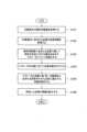
図5に、血管特定装置1を用いた血管特定方法における一連の処理を説明するフローチャートを示す。 FIG. 5 shows a flowchart illustrating a series of processes in a blood vessel identification method using the blood
図5のフローチャートのステップS101において、撮像装置20によって対象部位2の解析用画像を取得する。このとき、照明装置10によって対象部位に特定の波長の照射光Lを照射してもよい。 In step S101 of the flowchart in FIG. 5, an image for analysis of the
ステップS102において、画像処理装置31が解析用画像を画像処理して、対象部位2に含まれる血管の位置及び形状を含む血管情報を取得する。そして、ステップS103において、評価装置32が、血管情報を用いて、解析用画像に含まれる血管に関して特定の目的に対する適合性を示すパラメータについて点数化する。ステップS104において、対象部位2に含まれる複数の血管に関してパラメータをそれぞれ点数化し、パラメータの点数に応じて目的に適合する順に血管を順位付けしてもよい。その後、ステップS105において、特定装置33が、パラメータの点数に基づき、対象部位2に含まれる血管の中から目的に適合する適合血管を特定する。 In step S102, the
そして、ステップS106において、表示装置40が適合血管の情報を表示する。このとき、適合血管それぞれの適合箇所を、血管の順位と共に表示してもよい。 Then, in step S106, the
以上に説明したように、第1の実施形態に係る血管特定装置1では、対象部位2の解析用画像から、特定の目的に対する適合性を示すパラメータを点数化し、パラメータの点数に基づいて適合血管を特定する。血管特定装置1によれば、血管を可視化するだけでなく特定の目的に適合する血管を特定することができる。また、血管を順位付けして表示することにより、目的に適合する血管についてより的確な判定を行える。例えば最もパラメータの点数が高い血管を使用できない場合でも、他の血管を選択することが容易である。 As described above, in the blood
なお、上記に説明したパラメータの点数化では、各パラメータの点数がゼロ点になることはない。しかし、採血などの目的において許容し得ないパラメータがある血管が、合計点方式では順位が高くなってしまうこともあり得る。このリスクを回避するため、各パラメータについて、所定の許容範囲を超えた場合の点数をゼロ点にするようにしてもよい。更に、ゼロ点のパラメータが1つでもあれば、その血管を適合血管から排除するようにしてもよい。このようにすることで、特定のパラメータについては許容できない血管が適合血管として選択されるリスクの低減あるいは排除が可能である。 Note that in the parameter scoring described above, the score of each parameter does not become zero. However, a blood vessel with unacceptable parameters for purposes such as blood sampling may be ranked high in the total score system. In order to avoid this risk, each parameter may be given a score of zero if it exceeds a predetermined allowable range. Furthermore, if even one parameter has a zero point, that blood vessel may be excluded from the matching blood vessels. By doing so, it is possible to reduce or eliminate the risk that a blood vessel that is unacceptable for a particular parameter will be selected as a compatible blood vessel.
(第2の実施形態)
第1の実施形態では、適合血管の情報を表示装置40に表示する場合を説明した。一方、表示装置40に適合血管の情報を表示する代わりに、若しくは、表示装置40に適合血管の情報を表示すると共に、対象部位2に適合血管の情報を投影してもよい。図6に、対象部位2に適合血管の情報を投影する第2の実施形態に係る血管特定装置1の構成を示す。(Second embodiment)
In the first embodiment, a case has been described in which information on compatible blood vessels is displayed on the
図6に示す血管特定装置1は、表示装置40の代わりに、対象部位2に適合血管の情報を投影する投影装置50を備えることが図1と異なる点である。その他の構成については、図1に示す第1の実施形態と同様である。ただし、第2の実施形態に係る血管特定装置1が、表示装置40と共に投影装置50を備える構成であってもよい。 The blood
投影装置50は、例えば図7に示すように、解析用画像における適合血管の位置に対応させて、適合血管の適合箇所と順位を対象部位2に投影する。図7は、血管201~204が適合血管として特定され、血管201~204の適合箇所D1~D4を、血管201~204の順位と共に対象部位2に投影した例である。これにより、例えば針の穿刺しやすい部分を明確にできる。 For example, as shown in FIG. 7, the
また、図8に示すように、投影装置50が、適合血管の形状を近似した近似線を、適合血管の適合箇所や順位と共に対象部位2に投影してもよい。近似線は、解析用画像における適合血管の位置に対応させて対象部位2に投影される。投影される近似線は、例えば、第1の実施形態で説明した血管の直進性の評価のために作成された近似線であってもよい。図8は、血管201~204が適合血管として特定され、血管201~204の形状に近似した近似線C1~C4が表示された例である。これにより、適合血管の位置が明確に把握される。図8に示した例では、投影装置50が、適合血管の近似線C1~C4に適合箇所D1~D4を重ねて表示している。 Further, as shown in FIG. 8, the
なお、図9に示すように、適合箇所と共に特定の目的に適した方向を矢印などで投影してもよい。これにより、例えば針の穿刺が容易になる。血管の穿刺しやすい方向は、例えば血管の延伸方向である。 Note that, as shown in FIG. 9, a direction suitable for a specific purpose may be projected with an arrow or the like together with a suitable location. This facilitates needle puncture, for example. The direction in which the blood vessel is easily punctured is, for example, the direction in which the blood vessel extends.
図10に、第2の実施形態に係る血管特定装置1を用いた血管特定方法における一連の処理を説明するフローチャートを示す。 FIG. 10 shows a flowchart illustrating a series of processes in a blood vessel identification method using the blood
図10のフローチャートのステップS101~S105の処理は、図5に示したフローチャートのステップS101~S105の処理と同様である。そして、図10に示したフローチャートのステップS105の後、ステップS107において、投影装置50が適合血管の情報を対象部位2に投影する。即ち、適合血管の特定箇所や順位、近似線などが、適合血管の位置に対応させて対象部位2に投影される。 The processing in steps S101 to S105 in the flowchart in FIG. 10 is similar to the processing in steps S101 to S105 in the flowchart shown in FIG. After step S105 in the flowchart shown in FIG. 10, the
第2の実施形態に係る血管特定装置1によれば、対象部位2を目視しながら、特定の目的に適合した血管を絞り込むことができる。例えば、針を穿刺しやすい血管及びその血管の適合箇所の確認が容易である。他は、第1の実施形態と実質的に同様であり、重複した記載を省略する。 According to the blood
(その他の実施形態)
上記のように、本発明は実施形態によって記載したが、この開示の一部をなす論述及び図面はこの発明を限定するものであると理解すべきではない。この開示から当業者には様々な代替実施形態、実施例及び運用技術が明らかとなろう。(Other embodiments)
As described above, the present invention has been described by way of embodiments, but the statements and drawings that form part of this disclosure should not be understood as limiting the present invention. Various alternative embodiments, implementations, and operational techniques will be apparent to those skilled in the art from this disclosure.
例えば、血管特定装置1の演算装置30が、対象部位2の撮影場所から離れた場所に設置されていてもよい。 For example, the
このように、本発明はここでは記載していない様々な実施形態などを含むことはもちろんである。 Thus, it goes without saying that the present invention includes various embodiments not described here.
1…血管特定装置
2…対象部位
10…照明装置
20…撮像装置
30…演算装置
31…画像処理装置
32…評価装置
33…特定装置
40…表示装置
50…投影装置
201~205…血管1... Blood
Claims (22)
Translated fromJapanese前記血管情報を用いて、前記解析用画像に含まれる複数の血管それぞれに関して血管に針の穿刺しやすさという目的に対する適合性を示す複数のパラメータについて、適合の程度に応じて点数化する評価装置と、
複数の前記パラメータの合計点数に基づき、前記対象部位に含まれる複数の血管の中から前記目的に適合する適合血管を特定する特定装置と
を備え、
前記評価装置が、血管の延伸方向および前記解析用画像の特定地点からの距離の少なくともいずれかを前記パラメータの1つとして点数化することを特徴とする血管特定装置。an image processing device that processes an analysis image of a target region to obtain blood vessel information including the positions and shapes ofa plurality of blood vessels included in the target region;
An evaluation device that uses the blood vessel information to scorea plurality of parameters indicative of suitability for a purposeof ease of puncturing a blood vessel with a needle foreach ofa plurality of blood vessels included in the analysis image according to the degree of suitability. and,
a specifying device that identifies a blood vessel suitable for the purpose from amonga plurality of blood vessels included in the target region based onthe total score of theplurality of parameters;
A blood vessel specifying device, wherein the evaluation device scores at least one of the extending direction of the blood vessel and the distance from the specific point of the analysis image as one of the parameters.
前記適合血管の前記目的に適合する適合箇所が、前記適合血管それぞれの順位又は前記パラメータの合計点のいずれか一方と共に表示されることを特徴とする請求項1又は2に記載の血管特定装置。the evaluation device scores each of the parameters for a plurality of blood vessels included in the target region, and ranks the blood vessels in an order that is compatible with the purpose;
3. The blood vessel specifying device according to claim1 , wherein the matching location of the matching blood vessel that meets the purpose is displayed together with either a ranking of each of the matching blood vessels or a total score of the parameters.
ゼロ点の前記パラメータが1つでもある前記血管を前記適合血管から排除することを特徴とする請求項3に記載の血管特定装置。the evaluation devicezeroes the score of the parameter that exceeds a predetermined tolerance;
The blood vessel identifying device according to claim3, wherein the blood vessel in which at least one of the parameters has a zero point is excluded from the matching blood vessels .
前記対象部位を撮影して前記解析用画像を取得する撮像装置と
を更に備え、
前記特定の波長が、前記照射光が前記対象部位に照射されることにより、前記照射光が照射されない場合よりも血管と他の領域との境界が明確である前記解析用画像が前記撮像装置によって取得されるように選択されていることを特徴とする請求項1乃至8のいずれか1項に記載の血管特定装置。an illumination device that irradiates the target region with irradiation light of a specific wavelength;
further comprising: an imaging device that photographs the target region to obtain the analysis image;
When the target region is irradiated with the irradiation light using the specific wavelength, the analysis image in which the boundary between blood vessels and other regions is clearer than when the irradiation light is not irradiated is obtained by the imaging device. The blood vessel identifying device according to any one of claims 1 to8 , wherein the blood vessel identifying device is selected to be acquired.
前記血管情報を用いて、前記解析用画像に含まれる複数の血管それぞれに関して血管に針の穿刺しやすさという目的に対する適合性を示す複数のパラメータについて、適合の程度に応じて点数化するステップと、
複数の前記パラメータの合計点数に基づき、前記対象部位に含まれる複数の血管の中から前記目的に適合する適合血管を特定するステップと
を含み、
血管の延伸方向および前記解析用画像の特定地点からの距離の少なくともいずれかを前記パラメータの1つとして点数化することを特徴とする血管特定方法。performing image processing on an analysis image of the target region to obtain blood vessel information including the positions and shapes ofa plurality of blood vessels included in the target region;
using the blood vessel information to scorea plurality of parameters indicative of suitability for the purposeof ease of puncturing a blood vessel with a needle foreach ofthe plurality of blood vessels included in the analysis image according to the degree of suitability; ,
identifying a blood vessel suitable for the purpose from amonga plurality of blood vessels included in the target region, based on thetotal score of theplurality of parameters;
A blood vessel specifying method, characterizedin that at least one of the extending direction of the blood vessel and the distance from the specific point of the analysis image is scored as one of the parameters.
前記適合血管の前記目的に適合する適合箇所を、前記適合血管それぞれの順位又は前記パラメータの合計点のいずれか一方と共に表示する
ことを特徴とする請求項12又は13に記載の血管特定方法。scoring each of the parameters with respect to the plurality of blood vessels included in the target region, and ranking the blood vessels in the order that meets the purpose;
The blood vessel specifying method according to claim 12or 13 , characterized in that the matching portion of the matching blood vessel that meets the purpose is displayed together with either the ranking of each of the matching blood vessels or the total score of the parameters.
ゼロ点の前記パラメータが1つでもある前記血管を前記適合血管から排除することを特徴とする請求項14に記載の血管特定方法。The score of the parameter exceeding a predetermined toleranceis set to zero,
15. The blood vessel identification method according to claim14, wherein the blood vessel having at least one of the parameters having a zero point is excluded from the matching blood vessels .
前記特定の波長が、前記照射光が前記対象部位に照射されることにより、前記照射光が照射されない場合よりも血管と他の領域との境界が明確である前記解析用画像が取得されように選択されていることを特徴とする請求項12乃至19のいずれか1項に記載の血管特定方法。further comprising the step of photographing the target region while irradiating the target region with irradiation light of a specific wavelength to obtain the analysis image;
The specific wavelength is such that when the target region is irradiated with the irradiation light, the analysis image in which the boundary between blood vessels and other regions is clearer than when the irradiation light is not irradiated is obtained. The blood vessel identifying method according to any one of claims 12 to19 , wherein the blood vessel is selected.
Priority Applications (5)
| Application Number | Priority Date | Filing Date | Title |
|---|---|---|---|
| JP2019091843AJP7366360B2 (en) | 2019-05-15 | 2019-05-15 | Blood vessel identification device and blood vessel identification method |
| CN202080035768.6ACN113840567B (en) | 2019-05-15 | 2020-02-28 | Blood vessel identification device and blood vessel identification method |
| PCT/JP2020/008320WO2020230408A1 (en) | 2019-05-15 | 2020-02-28 | Blood vessel specification device and blood vessel specification method |
| US17/611,078US12357771B2 (en) | 2019-05-15 | 2020-02-28 | Blood vessel specifying device and blood vessel specifying method |
| TW109108600ATWI775057B (en) | 2019-05-15 | 2020-03-16 | Blood vessel specifying device and blood vessel specifying method |
Applications Claiming Priority (1)
| Application Number | Priority Date | Filing Date | Title |
|---|---|---|---|
| JP2019091843AJP7366360B2 (en) | 2019-05-15 | 2019-05-15 | Blood vessel identification device and blood vessel identification method |
Publications (2)
| Publication Number | Publication Date |
|---|---|
| JP2020185199A JP2020185199A (en) | 2020-11-19 |
| JP7366360B2true JP7366360B2 (en) | 2023-10-23 |
Family
ID=73220870
Family Applications (1)
| Application Number | Title | Priority Date | Filing Date |
|---|---|---|---|
| JP2019091843AActiveJP7366360B2 (en) | 2019-05-15 | 2019-05-15 | Blood vessel identification device and blood vessel identification method |
Country Status (5)
| Country | Link |
|---|---|
| US (1) | US12357771B2 (en) |
| JP (1) | JP7366360B2 (en) |
| CN (1) | CN113840567B (en) |
| TW (1) | TWI775057B (en) |
| WO (1) | WO2020230408A1 (en) |
Families Citing this family (5)
| Publication number | Priority date | Publication date | Assignee | Title |
|---|---|---|---|---|
| WO2023121860A2 (en)* | 2021-12-23 | 2023-06-29 | Rutgers, The State University Of New Jersey. | Systems and methods for automated peripheral vessel catheterization |
| CN114469008A (en)* | 2022-03-09 | 2022-05-13 | 浙江大学 | An intelligent grading device for vascular puncture difficulty based on near-infrared imaging of blood vessels |
| CN116036421B (en)* | 2023-01-19 | 2023-12-22 | 成都市凯瑞医疗科技有限公司 | Intelligent wearable automatic puncture equipment |
| CN116328081B (en)* | 2023-04-07 | 2025-04-11 | 北京艺升控股有限公司 | An injection system |
| JP2024151254A (en)* | 2023-04-11 | 2024-10-24 | 株式会社日立ハイテク | Blood collection device and method |
Citations (6)
| Publication number | Priority date | Publication date | Assignee | Title |
|---|---|---|---|---|
| JP2006102110A (en) | 2004-10-05 | 2006-04-20 | Matsushita Electric Ind Co Ltd | Blood vessel position presentation device |
| JP2008539932A (en) | 2005-05-10 | 2008-11-20 | コーニンクレッカ フィリップス エレクトロニクス エヌ ヴィ | Cannula insertion system |
| JP2014161672A (en) | 2013-02-27 | 2014-09-08 | Olympus Corp | Image processing apparatus, image processing method and image processing program |
| US20150065916A1 (en) | 2013-08-29 | 2015-03-05 | Vasculogic, Llc | Fully automated vascular imaging and access system |
| JP2017164046A (en) | 2016-03-14 | 2017-09-21 | 株式会社東芝 | Vein visualization device and vein visualization method |
| US20190126008A1 (en) | 2017-10-27 | 2019-05-02 | Siemens Healthcare Gmbh | Determining a vessel puncture position |
Family Cites Families (12)
| Publication number | Priority date | Publication date | Assignee | Title |
|---|---|---|---|---|
| US6556858B1 (en) | 2000-01-19 | 2003-04-29 | Herbert D. Zeman | Diffuse infrared light imaging system |
| ATE424872T1 (en)* | 2005-04-22 | 2009-03-15 | Koninkl Philips Electronics Nv | CANNULA INSERTION SYSTEM WITH TISSUE ANALYZING AGENTS |
| US8473030B2 (en)* | 2007-01-12 | 2013-06-25 | Medtronic Vascular, Inc. | Vessel position and configuration imaging apparatus and methods |
| JP2009172077A (en)* | 2008-01-23 | 2009-08-06 | Panasonic Corp | Blood vessel position acquisition device and blood vessel position acquisition method |
| JP5690556B2 (en)* | 2010-11-12 | 2015-03-25 | 株式会社 日立産業制御ソリューションズ | Personal authentication device |
| JP5818458B2 (en)* | 2011-02-25 | 2015-11-18 | キヤノン株式会社 | Image processing apparatus, photographing system, image processing method, and program |
| CN103987324B (en)* | 2012-11-09 | 2017-03-01 | 东芝医疗系统株式会社 | Puncture auxiliary device |
| JP6127207B2 (en) | 2013-05-13 | 2017-05-10 | 執鼎医療科技(杭州)有限公司 | Blood vessel image positioning system |
| JP6063357B2 (en)* | 2013-07-08 | 2017-01-18 | 国立大学法人大阪大学 | Blood collection support system using schema |
| TWM473188U (en)* | 2013-10-25 | 2014-03-01 | Nat Univ Chung Hsing | Cardiovascular sclerosis recognition system with ECG-assisted and oximetry pulse measurement |
| GB201414496D0 (en)* | 2014-08-15 | 2014-10-01 | Isis Innovation | Method |
| CN109247910B (en)* | 2017-07-12 | 2020-12-15 | 京东方科技集团股份有限公司 | Blood vessel display device and blood vessel display method |
- 2019
- 2019-05-15JPJP2019091843Apatent/JP7366360B2/enactiveActive
- 2020
- 2020-02-28USUS17/611,078patent/US12357771B2/enactiveActive
- 2020-02-28CNCN202080035768.6Apatent/CN113840567B/enactiveActive
- 2020-02-28WOPCT/JP2020/008320patent/WO2020230408A1/ennot_activeCeased
- 2020-03-16TWTW109108600Apatent/TWI775057B/enactive
Patent Citations (6)
| Publication number | Priority date | Publication date | Assignee | Title |
|---|---|---|---|---|
| JP2006102110A (en) | 2004-10-05 | 2006-04-20 | Matsushita Electric Ind Co Ltd | Blood vessel position presentation device |
| JP2008539932A (en) | 2005-05-10 | 2008-11-20 | コーニンクレッカ フィリップス エレクトロニクス エヌ ヴィ | Cannula insertion system |
| JP2014161672A (en) | 2013-02-27 | 2014-09-08 | Olympus Corp | Image processing apparatus, image processing method and image processing program |
| US20150065916A1 (en) | 2013-08-29 | 2015-03-05 | Vasculogic, Llc | Fully automated vascular imaging and access system |
| JP2017164046A (en) | 2016-03-14 | 2017-09-21 | 株式会社東芝 | Vein visualization device and vein visualization method |
| US20190126008A1 (en) | 2017-10-27 | 2019-05-02 | Siemens Healthcare Gmbh | Determining a vessel puncture position |
Also Published As
| Publication number | Publication date |
|---|---|
| US20220257874A1 (en) | 2022-08-18 |
| TW202042752A (en) | 2020-12-01 |
| US12357771B2 (en) | 2025-07-15 |
| CN113840567A (en) | 2021-12-24 |
| TWI775057B (en) | 2022-08-21 |
| WO2020230408A1 (en) | 2020-11-19 |
| JP2020185199A (en) | 2020-11-19 |
| CN113840567B (en) | 2024-06-25 |
Similar Documents
| Publication | Publication Date | Title |
|---|---|---|
| JP7366360B2 (en) | Blood vessel identification device and blood vessel identification method | |
| US10244991B2 (en) | Method and system for providing recommendation for optimal execution of surgical procedures | |
| JP2022543643A (en) | Longitudinal display of coronary artery calcium load | |
| US20160239959A1 (en) | Automatic Focused Assessment with Sonography for Trauma Exams | |
| JP5007420B2 (en) | Image analysis system and image analysis program | |
| JP2004057804A (en) | Method and apparatus for evaluating joint and program therefor | |
| US7873196B2 (en) | Medical imaging visibility index system and method for cancer lesions | |
| JP6644075B2 (en) | Image processing apparatus, image processing method, and image processing program | |
| US9014452B2 (en) | Orientation-aware average intensity histogram to indicate object boundary depth in ultrasound images | |
| JP3842171B2 (en) | Tomographic image processing device | |
| JP2009100943A (en) | Bone measuring apparatus and bone image processing method | |
| CN110598652A (en) | Fundus data prediction method and device | |
| JP2007152105A (en) | Method and apparatus for calculating volume of cerebral hemorrhage site | |
| JP6647703B2 (en) | Surgery training program | |
| Opolski et al. | A computed tomography algorithm for crossing coronary chronic total occlusions: riding on the wave of the proximal cap and distal vessel segment | |
| WO2020230407A1 (en) | Blood vessel position display device and blood vessel position display method | |
| KR102122767B1 (en) | Apparatus and method for ultrasonography | |
| JP2015150369A (en) | Stent detector, stent image display device, stent detecting program, and stent detecting method | |
| Gordon et al. | Automated measurement of radiographic hip joint‐space width | |
| US20170319107A1 (en) | Image-based detection and diagnosis of diastasis recti | |
| Wong et al. | Applying machine learning and point-set registration to automatically measure the severity of spinal curvature on radiographs | |
| Smith et al. | Detection of fracture and quantitative assessment of displacement measures in pelvic X-RAY images | |
| WO2008035425A1 (en) | Eyeground image analysis and program | |
| Nam et al. | Automated measurement of retinal vessel diameters on digital fundus photographs | |
| KR20200121550A (en) | Method for evaluating foot type and device evaluating foot type using the same |
Legal Events
| Date | Code | Title | Description |
|---|---|---|---|
| A621 | Written request for application examination | Free format text:JAPANESE INTERMEDIATE CODE: A621 Effective date:20220404 | |
| A131 | Notification of reasons for refusal | Free format text:JAPANESE INTERMEDIATE CODE: A131 Effective date:20230516 | |
| A521 | Request for written amendment filed | Free format text:JAPANESE INTERMEDIATE CODE: A523 Effective date:20230613 | |
| TRDD | Decision of grant or rejection written | ||
| A01 | Written decision to grant a patent or to grant a registration (utility model) | Free format text:JAPANESE INTERMEDIATE CODE: A01 Effective date:20230912 | |
| A61 | First payment of annual fees (during grant procedure) | Free format text:JAPANESE INTERMEDIATE CODE: A61 Effective date:20231002 | |
| R150 | Certificate of patent or registration of utility model | Ref document number:7366360 Country of ref document:JP Free format text:JAPANESE INTERMEDIATE CODE: R150 |