JP7361690B2 - New Radio (NR) Remaining Minimum System Information (RMSI) multiplexing and periodic considerations - Google Patents
New Radio (NR) Remaining Minimum System Information (RMSI) multiplexing and periodic considerationsDownload PDFInfo
- Publication number
- JP7361690B2 JP7361690B2JP2020527962AJP2020527962AJP7361690B2JP 7361690 B2JP7361690 B2JP 7361690B2JP 2020527962 AJP2020527962 AJP 2020527962AJP 2020527962 AJP2020527962 AJP 2020527962AJP 7361690 B2JP7361690 B2JP 7361690B2
- Authority
- JP
- Japan
- Prior art keywords
- multiplexing
- period
- rmsi
- type
- processor
- Prior art date
- Legal status (The legal status is an assumption and is not a legal conclusion. Google has not performed a legal analysis and makes no representation as to the accuracy of the status listed.)
- Active
Links
Images


Classifications
- H—ELECTRICITY
- H04—ELECTRIC COMMUNICATION TECHNIQUE
- H04L—TRANSMISSION OF DIGITAL INFORMATION, e.g. TELEGRAPHIC COMMUNICATION
- H04L27/00—Modulated-carrier systems
- H04L27/26—Systems using multi-frequency codes
- H04L27/2601—Multicarrier modulation systems
- H04L27/2647—Arrangements specific to the receiver only
- H04L27/2655—Synchronisation arrangements
- H04L27/2668—Details of algorithms
- H04L27/2673—Details of algorithms characterised by synchronisation parameters
- H04L27/2676—Blind, i.e. without using known symbols
- H—ELECTRICITY
- H04—ELECTRIC COMMUNICATION TECHNIQUE
- H04L—TRANSMISSION OF DIGITAL INFORMATION, e.g. TELEGRAPHIC COMMUNICATION
- H04L5/00—Arrangements affording multiple use of the transmission path
- H04L5/003—Arrangements for allocating sub-channels of the transmission path
- H04L5/0048—Allocation of pilot signals, i.e. of signals known to the receiver
- H—ELECTRICITY
- H04—ELECTRIC COMMUNICATION TECHNIQUE
- H04J—MULTIPLEX COMMUNICATION
- H04J11/00—Orthogonal multiplex systems, e.g. using WALSH codes
- H04J11/0069—Cell search, i.e. determining cell identity [cell-ID]
- H—ELECTRICITY
- H04—ELECTRIC COMMUNICATION TECHNIQUE
- H04J—MULTIPLEX COMMUNICATION
- H04J3/00—Time-division multiplex systems
- H04J3/02—Details
- H04J3/06—Synchronising arrangements
- H—ELECTRICITY
- H04—ELECTRIC COMMUNICATION TECHNIQUE
- H04L—TRANSMISSION OF DIGITAL INFORMATION, e.g. TELEGRAPHIC COMMUNICATION
- H04L27/00—Modulated-carrier systems
- H04L27/26—Systems using multi-frequency codes
- H04L27/2601—Multicarrier modulation systems
- H04L27/2647—Arrangements specific to the receiver only
- H04L27/2655—Synchronisation arrangements
- H04L27/2666—Acquisition of further OFDM parameters, e.g. bandwidth, subcarrier spacing, or guard interval length
- H—ELECTRICITY
- H04—ELECTRIC COMMUNICATION TECHNIQUE
- H04L—TRANSMISSION OF DIGITAL INFORMATION, e.g. TELEGRAPHIC COMMUNICATION
- H04L5/00—Arrangements affording multiple use of the transmission path
- H04L5/003—Arrangements for allocating sub-channels of the transmission path
- H04L5/0053—Allocation of signalling, i.e. of overhead other than pilot signals
- H—ELECTRICITY
- H04—ELECTRIC COMMUNICATION TECHNIQUE
- H04L—TRANSMISSION OF DIGITAL INFORMATION, e.g. TELEGRAPHIC COMMUNICATION
- H04L5/00—Arrangements affording multiple use of the transmission path
- H04L5/0091—Signalling for the administration of the divided path, e.g. signalling of configuration information
- H04L5/0094—Indication of how sub-channels of the path are allocated
- H—ELECTRICITY
- H04—ELECTRIC COMMUNICATION TECHNIQUE
- H04W—WIRELESS COMMUNICATION NETWORKS
- H04W48/00—Access restriction; Network selection; Access point selection
- H04W48/08—Access restriction or access information delivery, e.g. discovery data delivery
- H04W48/12—Access restriction or access information delivery, e.g. discovery data delivery using downlink control channel
- H—ELECTRICITY
- H04—ELECTRIC COMMUNICATION TECHNIQUE
- H04W—WIRELESS COMMUNICATION NETWORKS
- H04W48/00—Access restriction; Network selection; Access point selection
- H04W48/16—Discovering, processing access restriction or access information
- H—ELECTRICITY
- H04—ELECTRIC COMMUNICATION TECHNIQUE
- H04W—WIRELESS COMMUNICATION NETWORKS
- H04W72/00—Local resource management
- H04W72/04—Wireless resource allocation
- H04W72/044—Wireless resource allocation based on the type of the allocated resource
- H04W72/0446—Resources in time domain, e.g. slots or frames
Landscapes
- Engineering & Computer Science (AREA)
- Signal Processing (AREA)
- Computer Networks & Wireless Communication (AREA)
- Computer Security & Cryptography (AREA)
- Databases & Information Systems (AREA)
- Mobile Radio Communication Systems (AREA)
Description
Translated fromJapanese関連出願の相互参照
本出願は、2017年11月22日に出願した米国仮特許出願第62/590,018号、および2018年11月20日に出願した「NEW RADIO (NR) REMAINING MINIMUM SYSTEM INFORMATION (RMSI) MULTIPLEXING AND PERIODICITY CONSIDERATIONS」という名称の米国非仮特許出願第16/197,085号の優先権および利益を主張し、両方の開示が、以下に完全に記載されるかのように、かつすべての適用可能な目的のために、それらの全体が参照により本明細書に組み込まれる。Cross-References to Related Applications This application is based on U.S. Provisional Patent Application No. 62/590,018, filed on November 22, 2017, and “NEW RADIO (NR) REMAINING MINIMUM SYSTEM INFORMATION (RMSI)” filed on November 20, 2018. ) MULTIPLEXING AND PERIODICITY CONSIDERATIONS'' claims priority to and benefits from U.S. Non-Provisional Patent Application No. 16/197,085, both disclosures of which are incorporated herein by reference, as if fully set forth below, and all applicable For this purpose, the entirety of these documents is incorporated herein by reference.
以下で論じられる技術の態様は全般に、ワイヤレス通信システムに関し、より詳細には、残存最小システム情報(RMSI:remaining minimum system information)の多重化のタイプおよび周期のシグナリングに関する。実施形態は、多重化モード(たとえば、PBCHでの制御シグナリングインジケータが、同期ブロック/信号内のRMSI制御リソースセット(coreset)多重化モードを示すことができる)、モニタリングウィンドウを設定すること、および周期をシグナリングするために構成された、様々なワイヤレス通信コンテキスト(たとえば、ミリ波(mmWave)およびサブ6GHz(Sub-6 GHz)配備)において使用するための通信デバイス、方法、およびシステムを可能にし、提供することができる。そのような機能は、ユーザエクスペリエンス改善に役立つようにモビリティおよびネットワークカバレージを改善し、向上させることを目標とする。 Aspects of the technology discussed below relate generally to wireless communication systems, and more particularly to signaling of remaining minimum system information (RMSI) multiplexing type and period. Embodiments include setting a multiplexing mode (e.g., a control signaling indicator on a PBCH can indicate an RMSI control resource set (coreset) multiplexing mode within a synchronization block/signal), a monitoring window, and a periodicity. enables and provides communication devices, methods, and systems for use in a variety of wireless communication contexts (e.g., millimeter wave (mmWave) and sub-6 GHz (Sub-6 GHz) deployments) configured to signal can do. Such features aim to improve and increase mobility and network coverage to help improve user experience.
ワイヤレス通信ネットワークは、音声、ビデオ、パケットデータ、メッセージング、ブロードキャストなどの様々な通信サービスを提供するために広く展開されている。これらのワイヤレスネットワークは、利用可能なネットワークリソースを共有することによって複数のユーザをサポートすることのできる多元接続ネットワークであり得る。通常は多元接続ネットワークであるそのようなネットワークは、利用可能なネットワークリソースを共有することによって、複数のユーザのための通信をサポートする。 Wireless communication networks are widely deployed to provide various communication services such as voice, video, packet data, messaging, broadcast, etc. These wireless networks may be multiple-access networks that can support multiple users by sharing available network resources. Such networks, typically multiple-access networks, support communication for multiple users by sharing available network resources.
ワイヤレス通信ネットワークは、いくつかのユーザ機器(UE)のための通信をサポートすることができる、いくつかの基地局またはノードBを含み得る。UEは、ダウンリンクおよびアップリンクを介して基地局と通信し得る。ダウンリンク(または順方向リンク)は基地局からUEへの通信リンクを指し、アップリンク(または逆方向リンク)はUEから基地局への通信リンクを指す。 A wireless communication network may include a number of base stations or Node Bs that can support communication for a number of user equipment (UE). A UE may communicate with a base station via the downlink and uplink. The downlink (or forward link) refers to the communication link from the base station to the UE, and the uplink (or reverse link) refers to the communication link from the UE to the base station.
基地局は、ダウンリンク上でUEにデータおよび制御情報を送信してもよく、かつ/またはアップリンク上でUEからデータおよび制御情報を受信してもよい。ダウンリンク上で、基地局からの送信は、ネイバー基地局からの、または他のワイヤレス無線周波数(RF)送信機からの送信に起因する干渉を受ける場合がある。アップリンク上で、UEからの送信は、ネイバー基地局と通信する他のUEのアップリンク送信からの、または他のワイヤレスRF送信機からの干渉を受ける場合がある。この干渉は、ダウンリンクとアップリンクの両方に関する性能を低下させる場合がある。 A base station may transmit data and control information to the UE on the downlink and/or receive data and control information from the UE on the uplink. On the downlink, transmissions from a base station may be subject to interference due to transmissions from neighboring base stations or from other wireless radio frequency (RF) transmitters. On the uplink, transmissions from a UE may be subject to interference from uplink transmissions of other UEs communicating with neighbor base stations or from other wireless RF transmitters. This interference may degrade performance on both the downlink and uplink.
モバイルブロードバンドアクセスに対する需要が増加し続けるにつれて、より多くのUEが長距離ワイヤレス通信ネットワークにアクセスし、より多くの短距離ワイヤレスシステムがコミュニティにおいて展開されて、干渉および輻輳ネットワークの可能性が増大する。モバイルブロードバンドアクセスへの増大する需要を満たすためだけではなく、モバイル通信のユーザエクスペリエンスを進化および向上させるために、研究開発がワイヤレス通信技術を進化させ続けている。 As the demand for mobile broadband access continues to increase, more UEs access long-range wireless communication networks and more short-range wireless systems are deployed in communities, increasing the potential for interference and congestion networks. Research and development continues to advance wireless communication technologies, not only to meet the increasing demand for mobile broadband access, but also to evolve and improve the user experience of mobile communications.
以下では、説明する技術の基本的理解を与えるために本開示のいくつかの態様を要約する。この要約は、本開示のすべての企図された特徴の広範な概観ではなく、本開示のすべての態様の主要または重要な要素を識別するものでもなく、本開示のいずれかまたはすべての態様の範囲を定めるものでもない。その唯一の目的は、後で提示するより詳細な説明の前置きとして、本開示の1つまたは複数の態様のいくつかの概念を概要の形で提示することである。 The following summarizes some aspects of the disclosure in order to provide a basic understanding of the described technology. This summary is not an extensive overview of all contemplated features of the disclosure, does not identify key or critical elements of all aspects of the disclosure, and does not identify the scope of any or all aspects of the disclosure. It is not intended to determine. Its sole purpose is to present some concepts of one or more aspects of the disclosure in a summary form as a prelude to the more detailed description that is presented later.
ニューラジオ(NR)では、システム情報(SI)を搬送するために残存最小システム情報(RMSI)を使用することができる。物理ブロードキャストチャネル(PBCH)マスタ情報ブロック(MIB)は、ユーザ機器(UE)がネットワークにアクセスするために必要とするシステム情報の第1の部分を搬送することができる。RMSIは、UEがネットワークにアクセスするのに必要であるすべての残存システム情報を搬送することができる。このように、RMSIは、ロングタームエボリューション(LTE)におけるシステム情報ブロック(SIB)SIB1およびSIB2と同様であってもよい。しかしNRでは、RMSIを送信、受信、および識別するための機能または機構は、まだ完全に定義も配備もされていない。実施形態は、以下でより詳細に説明するようにこれらおよび他の機能を提供する。 New Radio (NR) may use Minimum Remaining System Information (RMSI) to convey system information (SI). A physical broadcast channel (PBCH) master information block (MIB) may carry a first portion of system information needed by user equipment (UE) to access the network. The RMSI may carry all residual system information necessary for the UE to access the network. In this way, RMSI may be similar to system information blocks (SIBs) SIB1 and SIB2 in Long Term Evolution (LTE). However, in NR, the functionality or mechanism for transmitting, receiving, and identifying RMSI is not yet fully defined or deployed. Embodiments provide these and other features as described in more detail below.
本開示の一態様では、ワイヤレス通信の方法が提供される。たとえば、方法は、残存最小システム情報(RMSI)の送信に対して多重化のタイプおよび周期を基地局によって決定するステップを含むことができ、多重化のタイプは、RMSIを同期信号(SS)ブロックと多重化するためのものである。この方法はまた、多重化のタイプおよび周期をシグナリングするインジケータを基地局によって生成するステップを含むことができる。 In one aspect of the disclosure, a method of wireless communication is provided. For example, the method can include determining, by a base station, a multiplexing type and periodicity for transmission of minimum remaining system information (RMSI), and the multiplexing type includes the RMSI as a synchronization signal (SS) block. This is for multiplexing. The method may also include generating an indicator by the base station that signals the type and period of multiplexing.
別の態様では、基地局が提供される。たとえば、基地局は、残存最小システム情報(RMSI)の送信に対して多重化のタイプおよび周期を基地局によって決定するための手段を有することができ、多重化のタイプは、RMSIを同期信号(SS)ブロックと多重化するためのものである。基地局はまた、多重化のタイプおよび周期をシグナリングするインジケータを基地局によって生成するための手段を含むことができる。 In another aspect, a base station is provided. For example, the base station may have means for determining by the base station a multiplexing type and periodicity for the transmission of minimum remaining system information (RMSI), where the multiplexing type determines the RMSI as a synchronization signal ( This is for multiplexing with SS) blocks. The base station may also include means for generating an indicator by the base station to signal the type and period of multiplexing.
別の態様では、基地局が提供される。たとえば、基地局は、少なくとも1つのプロセッサと、少なくとも1つのプロセッサに結合された少なくとも1つのメモリとを含むことができる。少なくとも1つのプロセッサは、残存最小システム情報(RMSI)の送信に対して多重化のタイプおよび周期を基地局によって決定するように構成され、多重化のタイプは、RMSIを同期信号(SS)ブロックと多重化するためのものである。少なくとも1つのプロセッサはまた、多重化のタイプおよび周期をシグナリングするインジケータを基地局によって生成するように構成される。 In another aspect, a base station is provided. For example, a base station can include at least one processor and at least one memory coupled to the at least one processor. The at least one processor is configured to determine by the base station a multiplexing type and periodicity for transmission of minimum remaining system information (RMSI), the multiplexing type including the RMSI with a synchronization signal (SS) block; It is for multiplexing. The at least one processor is also configured to generate an indicator signaling the type and period of multiplexing by the base station.
別の態様では、その上に命令を記録したコンピュータ可読媒体が提供される。1つまたは複数のコンピュータプロセッサによって実行されるとき、命令は、1つまたは複数のコンピュータプロセッサに、残存最小システム情報(RMSI)の送信に対して多重化のタイプおよび周期を基地局によって決定させ、多重化のタイプは、RMSIを同期信号(SS)ブロックと多重化するためのものである。命令はまた、1つまたは複数のコンピュータプロセッサに、多重化のタイプおよび周期をシグナリングするインジケータを基地局によって生成させる。 In another aspect, a computer readable medium having instructions recorded thereon is provided. When executed by the one or more computer processors, the instructions cause the one or more computer processors to determine a multiplexing type and periodicity for transmission of minimum residual system information (RMSI) by the base station; The type of multiplexing is for multiplexing RMSI with synchronization signal (SS) blocks. The instructions also cause the one or more computer processors to generate indicators signaling the type and period of multiplexing by the base station.
別の態様では、ワイヤレス通信の方法が提供される。たとえば、方法は、基地局による残存最小システム情報(RMSI)の送信に対して多重化のタイプおよび周期をシグナリングするインジケータをユーザ機器(UE)によって識別するステップを含んでもよく、多重化のタイプは、RMSIを同期信号SSブロックと多重化するためのものである。方法はまた、インジケータに基づいて多重化のタイプおよび周期をUEによって決定するステップを含んでもよい。方法はさらに、多重化のタイプおよび周期に基づいてRMSIの送信をUEによって処理するステップを含んでもよい。 In another aspect, a method of wireless communication is provided. For example, the method may include identifying by the user equipment (UE) an indicator that signals the type and periodicity of the multiplexing for transmission of minimum remaining system information (RMSI) by the base station, where the type of multiplexing is , RMSI and the synchronization signal SS block. The method may also include determining by the UE a type and periodicity of multiplexing based on the indicator. The method may further include processing the RMSI transmission by the UE based on the multiplexing type and period.
別の態様では、ユーザ機器(UE)が提供される。たとえば、装置は、基地局による残存最小システム情報(RMSI)の送信に対して多重化のタイプおよび周期をシグナリングするインジケータをUEによって識別するための手段を含んでもよく、多重化のタイプは、RMSIを同期信号SSブロックと多重化するためのものである。UEはまた、インジケータに基づいて多重化のタイプおよび周期をUEによって決定するための手段を含む。UEはさらに、多重化のタイプおよび周期に基づいてRMSIの送信をUEによって処理するための手段を含む。 In another aspect, a user equipment (UE) is provided. For example, the apparatus may include means for identifying by the UE an indicator signaling a type and periodicity of multiplexing for transmission of minimum remaining system information (RMSI) by a base station, where the type of multiplexing is This is for multiplexing the synchronization signal SS block with the synchronization signal SS block. The UE also includes means for determining by the UE a type and periodicity of multiplexing based on the indicator. The UE further includes means for processing the RMSI transmission by the UE based on the multiplexing type and period.
別の態様では、ユーザ機器(UE)が提供される。たとえば、UEは、通信インターフェースと電気通信している少なくとも1つのプロセッサと、少なくとも1つのプロセッサに結合された少なくとも1つのメモリとを含んでもよい。少なくとも1つのプロセッサは、基地局による残存最小システム情報(RMSI)の送信に対して多重化のタイプおよび周期をシグナリングするインジケータを、通信インターフェースによって識別するように構成され、多重化のタイプは、RMSIを同期信号SSブロックと多重化するためのものである。少なくとも1つのプロセッサはまた、インジケータに基づいて多重化のタイプおよび周期をUEによって決定するように構成される。少なくとも1つのプロセッサはさらに、多重化のタイプおよび周期に基づいてRMSIの送信をUEによって処理するように構成される。 In another aspect, a user equipment (UE) is provided. For example, a UE may include at least one processor in electrical communication with a communication interface and at least one memory coupled to the at least one processor. The at least one processor is configured to identify, through the communication interface, an indicator that signals a multiplexing type and periodicity for transmission of minimum remaining system information (RMSI) by the base station, wherein the multiplexing type is RMSI This is for multiplexing the synchronization signal SS block with the synchronization signal SS block. The at least one processor is also configured to determine the type and periodicity of multiplexing by the UE based on the indicator. The at least one processor is further configured to process the transmission of the RMSI by the UE based on the multiplexing type and period.
別の態様では、コンピュータ可読媒体が提供される。たとえば、コンピュータ可読媒体は、1つまたは複数のコンピュータプロセッサによって実行されるとき、1つまたは複数のコンピュータプロセッサが、基地局による残存最小システム情報(RMSI)の送信に対して多重化のタイプおよび周期をシグナリングするインジケータをユーザ機器(UE)によって識別するようにする命令をその上に記録され、多重化のタイプは、RMSIを同期信号SSブロックと多重化するためのものである。命令はまた、1つまたは複数のコンピュータプロセッサが、インジケータに基づいて多重化のタイプおよび周期をUEによって決定するようにする。命令はさらに、1つまたは複数のコンピュータプロセッサが、多重化のタイプおよび周期に基づいてRMSIの送信をUEによって処理するようにする。 In another aspect, a computer readable medium is provided. For example, when the computer-readable medium is executed by one or more computer processors, the one or more computer processors may transmit multiplexing types and periods for transmission of minimum remaining system information (RMSI) by a base station. The type of multiplexing is for multiplexing the RMSI with the synchronization signal SS block. The instructions also cause the one or more computer processors to determine the type and period of multiplexing by the UE based on the indicator. The instructions further cause the one or more computer processors to process transmissions of RMSI by the UE based on the multiplexing type and periodicity.
別の態様では、ワイヤレス通信装置が、少なくとも1つのプロセッサと、少なくとも1つのプロセッサに結合された少なくとも1つのメモリとを有する。少なくとも1つのプロセッサは、基地局による残存最小システム情報(RMSI)の送信に対して多重化のタイプおよび周期をシグナリングするインジケータを、ユーザ機器(UE)によって識別するように構成され、多重化のタイプは、RMSIを同期信号SSブロックと多重化するためのものである。少なくとも1つのプロセッサはその上、インジケータに基づいて多重化のタイプおよび周期をUEによって決定するように構成される。少なくとも1つのプロセッサはまた、多重化のタイプおよび周期に基づいてRMSIの次の送信をUEによって処理するように構成される。 In another aspect, a wireless communication device has at least one processor and at least one memory coupled to the at least one processor. The at least one processor is configured to identify, by the user equipment (UE), an indicator that signals a type of multiplexing and a periodicity for transmission of minimum remaining system information (RMSI) by the base station; is for multiplexing RMSI with the synchronization signal SS block. The at least one processor is further configured to determine the type and periodicity of multiplexing by the UE based on the indicator. The at least one processor is also configured to process subsequent transmissions of the RMSI by the UE based on the multiplexing type and period.
添付の図とともに特定の例示的な実施形態の以下の説明を検討すれば、他の態様、特徴、および実施形態が当業者に明らかとなろう。特徴について、以下のいくつかの実施形態および図に対して説明する場合があるが、すべての実施形態は、本明細書で説明する有利な特徴のうちの1つまたは複数を含むことができる。言い換えれば、1つまたは複数の実施形態がいくつかの有利な特徴を有するものとして説明されることがあるが、そのような特徴のうちの1つまたは複数はまた、本明細書で説明する様々な実施形態に従って使用され得る。同様に、例示的な実施形態がデバイス実施形態、システム実施形態、または方法実施形態として以下で説明されることがあるが、そのような例示的な実施形態が、様々なデバイス、システム、および方法で実装され得ることを理解されたい。 Other aspects, features, and embodiments will be apparent to those skilled in the art upon consideration of the following description of certain exemplary embodiments in conjunction with the accompanying figures. Although features may be described with respect to some embodiments and figures below, all embodiments can include one or more of the advantageous features described herein. In other words, although one or more embodiments may be described as having several advantageous features, one or more of such features may also be may be used in accordance with other embodiments. Similarly, although example embodiments may be described below as device embodiments, system embodiments, or method embodiments, such example embodiments may be incorporated into various devices, systems, and methods. It should be understood that it can be implemented with
以下の図面を参照することによって、本開示の本質および利点のより一層の理解が実現され得る。添付の図面では、同様の構成要素または特徴は、同じ参照ラベルを有することがある。さらに、同じタイプの様々な構成要素が、参照ラベルの後に、ダッシュおよび類似の構成要素を区別する第2のラベルを続けることによって区別されることがある。第1の参照ラベルのみが本明細書において使用される場合、説明は、第2の参照ラベルにかかわらず、同じ第1の参照ラベルを有する類似の構成要素のうちのいずれにも適用可能である。 A further understanding of the nature and advantages of the present disclosure may be realized by reference to the following drawings. In the accompanying drawings, similar components or features may have the same reference label. Additionally, various components of the same type may be distinguished by following the reference label with a dash and a second label that distinguishes similar components. If only a first reference label is used herein, the description is applicable to any of the similar components having the same first reference label, regardless of the second reference label. .
添付の図面に関して以下に記載する発明を実施するための形態は、様々な可能な構成を説明するものであり、本開示の範囲を限定するものではない。むしろ、発明を実施するための形態は、本発明の主題の完全な理解を与えるための具体的な詳細を含む。これらの具体的な詳細がすべての場合に必要であるとは限らないこと、および場合によっては、提示を明快にするために、よく知られている構造および構成要素がブロック図の形態で示されることは当業者には明らかであろう。 The detailed description set forth below with respect to the accompanying drawings is illustrative of various possible configurations and is not intended to limit the scope of the disclosure. Rather, the detailed description includes specific details to provide a thorough understanding of the subject matter. It should be noted that these specific details may not be necessary in all cases, and in some cases, well-known structures and components are shown in block diagram form for clarity of presentation. This will be clear to those skilled in the art.
本開示は、一般に、ワイヤレス通信ネットワークとも呼ばれる、1つまたは複数のワイヤレス通信システムにおける2つ以上のワイヤレスデバイスの間の通信を実現すること、またはそれに参加することに関する。様々な実施形態では、技法および装置は、符号分割多元接続(CDMA)ネットワーク、時分割多元接続(TDMA)ネットワーク、周波数分割多元接続(FDMA)ネットワーク、直交FDMA(OFDMA)ネットワーク、シングルキャリアFDMA(SC-FDMA)ネットワーク、ロングタームエボリューション(LTE)ネットワーク、モバイル通信用グローバルシステム(GSM)ネットワーク、ならびに他の通信ネットワークなどのワイヤレス通信ネットワークに使用され得る。本明細書で説明する「ネットワーク」および「システム」という用語は、特定の文脈に従って互換的に使用され得る。 TECHNICAL FIELD This disclosure generally relates to implementing or participating in communications between two or more wireless devices in one or more wireless communication systems, also referred to as wireless communication networks. In various embodiments, the techniques and apparatus can be applied to code division multiple access (CDMA) networks, time division multiple access (TDMA) networks, frequency division multiple access (FDMA) networks, orthogonal FDMA (OFDMA) networks, single carrier FDMA (SC -FDMA) networks, Long Term Evolution (LTE) networks, Global System for Mobile Communications (GSM) networks, as well as other communication networks. The terms "network" and "system" described herein may be used interchangeably according to the particular context.
たとえば、CDMAネットワークは、ユニバーサル地上波無線アクセス(UTRA)、cdma2000などの無線技術を実装し得る。UTRAは、ワイドバンドCDMA(W-CDMA)および低チップレート(LCR)を含む。CDMA2000は、IS-2000規格、IS-95規格、およびIS-856規格を対象とする。 For example, a CDMA network may implement a radio technology such as Universal Terrestrial Radio Access (UTRA), cdma2000, or the like. UTRA includes Wideband CDMA (W-CDMA) and Low Chip Rate (LCR). CDMA2000 covers the IS-2000, IS-95, and IS-856 standards.
TDMAネットワークは、たとえば、GSMのような無線技術を実装し得る。3GPPは、GERANとしても示される、GSM EDGE(GSM進化型高速データレート)無線アクセスネットワーク(RAN)のための規格を定義する。GERANは、基地局(たとえば、AterインターフェースおよびAbisインターフェース)と基地局コントローラ(Aインターフェースなど)とを結合するネットワークとともに、GSM/EDGEの無線構成要素である。無線アクセスネットワークは、GSMネットワークの構成要素を表し、GSMネットワークを通じて、電話呼およびパケットデータが、公衆交換電話網(PSTN)およびインターネットと、ユーザ端末またはユーザ機器(UE)としても知られる加入者ハンドセットとの間でルーティングされる。モバイルフォン事業者のネットワークは、UMTS/GSMネットワークの場合にユニバーサル地上波無線アクセスネットワーク(UTRAN)と結合され得る、1つまたは複数のGERANを含む場合がある。事業者ネットワークは、1つもしくは複数のLTEネットワークおよび/または1つもしくは複数の他のネットワークを含む場合もある。様々な異なるネットワークタイプは、異なる無線アクセス技術(RAT)および無線アクセスネットワーク(RAN)を使用する場合がある。 A TDMA network may implement a wireless technology such as GSM, for example. 3GPP defines standards for the GSM EDGE (GSM Evolved High Data Rate) Radio Access Network (RAN), also referred to as GERAN. GERAN is the radio component of GSM/EDGE, along with the network coupling base stations (eg, Ater interface and Abis interface) and base station controllers (eg, A interface). A radio access network represents a component of a GSM network, through which telephone calls and packet data are transferred between the public switched telephone network (PSTN) and the Internet and subscriber handsets, also known as user terminals or user equipment (UE). routed between. A mobile phone operator's network may include one or more GERANs, which may be combined with a Universal Terrestrial Radio Access Network (UTRAN) in the case of a UMTS/GSM network. An operator network may also include one or more LTE networks and/or one or more other networks. Various different network types may use different radio access technologies (RATs) and radio access networks (RANs).
OFDMAネットワークは、たとえば、発展型UTRA(E-UTRA)、IEEE802.11、IEEE802.16、IEEE802.20、フラッシュOFDMなどの無線技術を実装し得る。UTRA、E-UTRA、およびGSMは、ユニバーサルモバイルテレコミュニケーションシステム(UMTS)の一部である。詳細には、LTEは、E-UTRAを使用するUMTSのリリースである。UTRA、E-UTRA、GSM、UMTSおよびLTEは、「第3世代パートナーシッププロジェクト」(3GPP)という名称の組織から提供された文書に記載されており、cdma2000は、「第3世代パートナーシッププロジェクト2」(3GPP2)という名称の組織からの文書に記載されている。これらの様々な無線技術および規格は、知られているか、または開発中である。たとえば、第3世代パートナーシッププロジェクト(3GPP)は、世界的に適用可能な第3世代(3G)モバイルフォン仕様を定義することを目的とする電気通信協会のグループ間の共同作業である。3GPPロングタームエボリューション(LTE)は、ユニバーサルモバイルテレコミュニケーションシステム(UMTS)モバイルフォン規格を改善することを目的とする3GPPプロジェクトである。3GPPは、次世代のモバイルネットワーク、モバイルシステム、およびモバイルデバイスのための仕様を定義し得る。 OFDMA networks may implement radio technologies such as, for example, Evolved UTRA (E-UTRA), IEEE 802.11, IEEE 802.16, IEEE 802.20, Flash OFDM, and the like. UTRA, E-UTRA, and GSM are part of the Universal Mobile Telecommunication System (UMTS). In detail, LTE is a release of UMTS that uses E-UTRA. UTRA, E-UTRA, GSM, UMTS and LTE are described in documents provided by an organization named "3rd Generation Partnership Project" (3GPP), and cdma2000 is described in documents provided by an organization named "3rd
明快のために、装置および技法のいくつかの態様について、NR(ニューラジオ)と例示的なLTE実装形態の両方を参照しながら以下で説明することができる。これらの説明は、本質的に例にすぎない。したがって、いくつかの説明は、LTE中心に行われる場合があり、以下の記述の部分において説明のための例としてLTE用語が使用される場合があるが、説明は、LTE適用例に限定されるものではない。またNRまたは5G用語を用いて行われる説明にも同じことが言える。結果として、本開示は、異なる無線アクセス技術または無線エアインターフェースを使用するネットワーク間のワイヤレススペクトルへの共有アクセスに関係する。さらに配備は、ライセンスおよびアンライセンススペクトルのシナリオの一方または両方を、周波数の範囲(たとえば、サブ6GHzからミリ波)にわたって、利用することができる。 For clarity, some aspects of apparatus and techniques may be described below with reference to both NR (New Radio) and example LTE implementations. These descriptions are merely exemplary in nature. Therefore, although some explanations may be centered around LTE, and LTE terminology may be used as examples for explanation in the following portion of the description, the explanation is limited to LTE application examples. It's not a thing. The same also applies to explanations made using NR or 5G terminology. As a result, the present disclosure relates to shared access to the wireless spectrum between networks using different radio access technologies or wireless air interfaces. Additionally, deployments may utilize one or both licensed and unlicensed spectrum scenarios across a range of frequencies (eg, sub-6 GHz to mmWave).
さらに、動作時、本明細書の概念に従って適合されたワイヤレス通信ネットワークは、負荷および利用可能度に応じてライセンスまたはアンライセンススペクトルの任意の組合せで動作する場合があることを理解されたい。したがって、本明細書で説明するシステム、装置、および方法が、示される特定の例以外の他の通信システムおよび適用例に適用され得ることが、当業者には明らかであろう。 Furthermore, it is to be understood that, in operation, a wireless communication network adapted according to the concepts herein may operate on any combination of licensed or unlicensed spectrum depending on load and availability. Accordingly, it will be apparent to those skilled in the art that the systems, apparatus, and methods described herein may be applied to other communication systems and applications other than the specific examples shown.
本出願ではいくつかの例への説明によって態様および実施形態を記述するが、さらなる実装形態および使用事例が多くの異なる構成およびシナリオにおいて発生する場合があることを当業者には理解されよう。本明細書で説明する新機軸は、多くの異なるプラットフォーム型、デバイス、システム、形状、サイズ、パッケージング構成にわたって実装されてもよい。たとえば、実施形態および/または用途は、集積チップ実施形態および/または他の非モジュールコンポーネントベースのデバイス(たとえば、エンドユーザのデバイス、車両、通信デバイス、コンピューティングデバイス、産業機器、小売り/購買デバイス、医療デバイス、AI対応デバイスなど)によって発生し得る。いくつかの例は、詳細には使用事例または適用例を対象とする、または対象としない場合があるが、説明する新機軸の幅広い種類の適用可能性が生じ得る。実装形態は、チップレベルまたはモジュール式のコンポーネントから、非モジュール式、非チップレベルの実装形態まで、さらに1つまたは複数の説明する態様を組み込んだ集約型、分散型、またはOEMデバイスまたはシステムまで多岐にわたり得る。いくつかの実際の設定では、説明する態様および特徴を組み込んだデバイスは、請求および説明する実施形態を実装および実践するための追加の構成要素および特徴もまた、必然的に含み得る。本明細書で説明する新機軸は、様々なサイズ、形状、および構造の、大規模/小規模デバイスの両方、チップレベルコンポーネント、マルチコンポーネントシステム(たとえば、RFチェーン、通信インターフェース、プロセッサ)、分散型構成、エンドユーザのデバイスなど、多種多様な実装形態において実践され得るものとする。 Although this application describes aspects and embodiments by way of illustration to several examples, those skilled in the art will appreciate that further implementations and use cases may occur in many different configurations and scenarios. The innovations described herein may be implemented across many different platform types, devices, systems, shapes, sizes, and packaging configurations. For example, embodiments and/or applications may include integrated chip embodiments and/or other non-modular component-based devices (e.g., end-user devices, vehicles, communication devices, computing devices, industrial equipment, retail/purchasing devices, medical devices, AI-enabled devices, etc.). Although some examples may or may not specifically target use cases or applications, a wide variety of possible applications of the described innovations may arise. Implementations range from chip-level or modular components to non-modular, non-chip-level implementations, to centralized, distributed, or OEM devices or systems incorporating one or more of the described aspects. can be extended. In some actual settings, devices incorporating the described aspects and features may necessarily also include additional components and features for implementing and practicing the claimed and described embodiments. The innovations described herein can be applied to devices of various sizes, shapes, and structures, both large and small, chip-level components, multi-component systems (e.g., RF chains, communication interfaces, processors), distributed It may be practiced in a wide variety of implementations, including configurations, end-user devices, and so on.
図1は、いくつかの実施形態による通信のためのワイヤレスネットワーク100を示す。本開示の技術の説明は、(図1に示す)LTE-Aネットワークに対して行われるが、これは例示のためである。開示される技術の原理は、第5世代(5G)またはニューラジオ(NR)ネットワークを含む、他のネットワーク展開において使用されてよい。当業者に諒解されるように、図1に表示する構成要素は、他のネットワーク構成、たとえば、セルラー型ネットワーク構成および非セルラー型ネットワーク構成(たとえば、デバイスツーデバイスまたはピアツーピアまたはアドホックネットワーク構成など)を含む関係する対応部分を有する可能性がある。 FIG. 1 illustrates a
図1に戻ると、ワイヤレスネットワーク100は、いくつかの基地局を含むことができる。これらは、発展型ノードB(eNB)またはGノードB(gNB)を含むことができる。これらは、gNB105と呼ばれることがある。gNBは、UEと通信する局であってよく、基地局、ノードB、アクセスポイントなどと呼ばれることもある。各gNB105は、特定の地理的エリアに通信カバレージを提供することがある。3GPPでは、「セル」という用語は、この用語が使用される文脈に応じて、カバレージエリアにサービスするgNBおよび/またはgNBサブシステムのこの特定の地理的カバレージエリアを指すことがある。本明細書におけるワイヤレスネットワーク100の実装形態では、gNB105は、同じ事業者または異なる事業者に関連している場合があり(たとえば、ワイヤレスネットワーク100は、複数の事業者のワイヤレスネットワークを含む場合がある)、隣接セルと、同じ周波数の1つまたは複数(たとえば、ライセンススペクトル、アンライセンススペクトル、またはそれらの組合せの1つまたは複数の同じ周波数帯)を使用してワイヤレス通信を提供する場合がある。 Returning to FIG. 1,
gNBは、マクロセル、またはピコセルもしくはフェムトセルなどのスモールセル、および/または他のタイプのセルに通信カバレージを提供することができる。マクロセルは一般に、比較的大きい地理的エリア(たとえば、半径数キロメートル)をカバーし、ネットワークプロバイダのサービスに加入しているUEによる無制限アクセスを可能にし得る。ピコセルなどのスモールセルは、一般に、比較的小さい地理的エリアをカバーし、ネットワークプロバイダのサービスに加入しているUEによる無制限アクセスを可能にすることができる。フェムトセルなどのスモールセルも、一般に、比較的小さい地理的エリア(たとえば、自宅)をカバーし、無制限アクセスに加えて、フェムトセルとの関連付けを有するUE(たとえば、限定加入者グループ(CSG)内のUE、自宅内のユーザのためのUEなど)による制限付きアクセスも提供することができる。マクロセルのためのgNBは、マクロgNBと呼ばれることがある。スモールセルのためのgNBは、スモールセルgNB、ピコgNB、フェムトgNB、またはホームgNBと呼ばれることがある。図1に示す例では、gNB105a、105b、および105cは、それぞれ、マクロセル110a、110b、および110cのためのマクロgNBである。gNB105x、105y、および105zは、それぞれ、スモールセル110x、110y、および110zにサービスを提供するピコgNBまたはフェムトgNBを含み得る、スモールセルgNBである。gNBは、1つまたは複数(たとえば、2つ、3つ、4つなど)のセルをサポートしてもよい。 A gNB may provide communication coverage to macro cells or small cells such as pico cells or femto cells, and/or other types of cells. A macro cell typically covers a relatively large geographic area (eg, several kilometers radius) and may allow unrestricted access by UEs subscribing to the network provider's services. Small cells, such as picocells, generally cover a relatively small geographic area and can allow unrestricted access by UEs subscribing to a network provider's services. Small cells, such as femtocells, also typically cover a relatively small geographic area (e.g., your home) and, in addition to unrestricted access, allow UEs with an association with the femtocell (e.g., within a limited subscriber group (CSG) limited access by the UE, UE for users within the home, etc.) may also be provided. A gNB for a macro cell is sometimes referred to as a macro gNB. A gNB for a small cell may be referred to as a small cell gNB, pico gNB, femto gNB, or home gNB. In the example shown in FIG. 1,
ワイヤレスネットワーク100は、同期動作または非同期動作をサポートし得る。同期動作の場合、gNBは、同様のフレームタイミングを有することができ、異なるgNBからの送信は、時間的にほぼ整合し得る。非同期動作の場合、gNBは、異なるフレームタイミングを有することがあり、異なるgNBからの送信は、時間的に整合していないことがある。いくつかのシナリオでは、ネットワークが、同期または非同期動作間で動的切替えを処理することを可能にされる、またはそのように構成されることがある。
UE115は、一般的にワイヤレスネットワーク100全体にわたって分散され、各UEは固定またはモバイルであり得る。モバイル装置は、第3世代パートナーシッププロジェクト(3GPP)によって公表された規格および仕様では、一般にユーザ機器(UE)と呼ばれるが、そのような装置は、当業者によって、移動局(MS)、加入者局、モバイルユニット、加入者ユニット、ワイヤレスユニット、リモートユニット、モバイルデバイス、ワイヤレスデバイス、ワイヤレス通信デバイス、リモートデバイス、モバイル加入者局、アクセス端末(AT)、モバイル端末、ワイヤレス端末、リモート端末、ハンドセット、端末、ユーザエージェント、モバイルクライアント、クライアント、または何らかの他の適切な用語で呼ばれることもあることを諒解されたい。本書内では、「モバイル」装置またはUEは、必ずしも移動するための能力を有する必要があるとは限らず、固定されていてもよい。UE115のうちの1つまたは複数の実施形態を含み得るようなモバイル装置のいくつかの非限定的な例には、モバイル、セルラー(セル)フォン、スマートフォン、セッション開始プロトコル(SIP)フォン、ラップトップ、パーソナルコンピュータ(PC)、ノートブック、ネットブック、スマートブック、タブレット、および携帯情報端末(PDA)が含まれる。
モバイル装置は、加えて、「モノのインターネット」(IoT)デバイスであり得る。IoTカテゴリに属するデバイスは、自動車または他の輸送車両、衛星無線、全地球測位システム(GPS)デバイス、物流コントローラ、ドローン、マルチコプター、クアッドコプター、スマートエネルギーまたはセキュリティデバイス、ソーラーパネルまたはソーラーアレイ、都市の電灯、水、または他のインフラストラクチャ、工業オートメーションおよびエンタープライズデバイス、アイウェア、ウェアラブルカメラ、スマートウォッチ、ヘルスまたはフィットネストラッカー、哺乳類埋込み可能デバイス、ジェスチャー追跡デバイス、医療デバイス、デジタルオーディオプレーヤ(たとえば、MP3プレーヤ)、カメラ、ゲームコンソールなどのコンシューマおよびウェアラブルデバイス、ならびに、ホームオーディオ、ビデオおよびマルチメディアデバイス、アプライアンス、センサー、自動販売機、インテリジェント照明、ホームセキュリティシステム、スマートメーターなどのデジタルホームまたはスマートホームデバイスなどの構成要素またはデバイスを含むことができる。 The mobile device may additionally be an "Internet of Things" (IoT) device. Devices that fall under the IoT category include automobiles or other transportation vehicles, satellite radios, Global Positioning System (GPS) devices, logistics controllers, drones, multicopters, quadcopters, smart energy or security devices, solar panels or solar arrays, urban lighting, water, or other infrastructure, industrial automation and enterprise devices, eyewear, wearable cameras, smart watches, health or fitness trackers, mammalian implantable devices, gesture tracking devices, medical devices, digital audio players (e.g., MP3 digital home or smart home devices such as home audio, video and multimedia devices, appliances, sensors, vending machines, intelligent lighting, home security systems, smart meters, etc. It may include components or devices such as.
UE115などのモバイル装置は、マクロgNB、ピコgNB、フェムトgNB、リレーなどと通信することが可能であり得る。図1では、稲妻(たとえば、通信リンク125)は、UEとサービングgNBとの間のワイヤレス送信、またはeNB間の所望の送信を示し、サービングgNBは、ダウンリンクおよび/またはアップリンク上でUEにサービスするように指定されたeNBである。バックホール通信134は、gNB間で発生し得るワイヤードバックホール通信として示されているが、バックホール通信が追加または代替としてワイヤレス通信によって実現されてもよいことを諒解されたい。 A mobile device such as
図2は、基地局/gNB105およびUE115の設計のブロック図を示す。これらは、図1の基地局/gNBのうちの1つおよびUEのうちの1つとすることができる。(上述のように)制限付き関連付けシナリオの場合、gNB105は図1のスモールセルgNB105zであってもよく、UE115はUE115zであってもよく、UE115zは、スモールセルgNB105zにアクセスするために、スモールセルgNB105zに対するアクセス可能UEのリストに含まれることになろう。gNB105はまた、何らかの他のタイプの基地局であり得る。gNB105は、アンテナ234a~234tを備えてもよく、UE115は、アンテナ252a~252rを備えてもよい。 FIG. 2 shows a block diagram of the design of base station/
gNB105において、送信プロセッサ220は、データソース212からデータを受信し、コントローラ/プロセッサ240から制御情報を受信することができる。制御情報は、物理ブロードキャストチャネル(PBCH)、物理制御フォーマットインジケータチャネル(PCFICH)、物理ハイブリッドARQインジケータチャネル(PHICH)、物理ダウンリンク制御チャネル(PDCCH)などに対するものであり得る。データは、物理ダウンリンク共有チャネル(PDSCH)に関するデータなどであってもよい。送信プロセッサ220は、データおよび制御情報を処理(たとえば、符号化およびシンボルマッピング)して、それぞれ、データシンボルおよび制御シンボルを取得することができる。送信プロセッサ220はまた、たとえば、1次同期信号(PSS)、2次同期信号(SSS)、およびセル固有基準信号(CRS)のための基準シンボルを生成し得る。送信(TX)多入力多出力(MIMO)プロセッサ230は、該当する場合、データシンボル、制御シンボル、および/または基準シンボルに対して空間処理(たとえば、プリコーディング)を行ってもよく、出力シンボルストリームを変調器(MOD)232a~232tを供給してもよい。各変調器232は、(たとえば、OFDM用などに)それぞれの出力シンボルストリームを処理して出力サンプルストリームを取得し得る。各変調器232は、追加または代替として、出力サンプルストリームを処理(たとえば、アナログに変換、増幅、フィルタ処理、およびアップコンバート)して、ダウンリンク信号を取得し得る。変調器232a~232tからのダウンリンク信号は、それぞれ、アンテナ234a~234tを介して送信され得る。 At
UE115において、アンテナ252a~252rは、gNB105からダウンリンク信号を受信することができ、受信信号を、それぞれ復調器(DEMOD)254a~254rに供給することができる。各復調器254は、それぞれの受信信号を調整(たとえば、フィルタリング、増幅、ダウンコンバート、およびデジタル化)して、入力サンプルを取得することができる。各復調器254は、(たとえば、OFDMなどのために)入力サンプルをさらに処理して、受信シンボルを取得することができる。MIMO検出器256は、すべての復調器254a~254rから受信シンボルを取得し、適用可能な場合、受信シンボルに対してMIMO検出を実行し、検出されたシンボルを提供することができる。受信プロセッサ258は、検出されたシンボルを処理(たとえば、復調、デインターリーブ、および復号)し、UE115のための復号されたデータをデータシンク260に供給し、復号された制御情報をコントローラ/プロセッサ280に供給することができる。 At
アップリンク上で、UE115において、送信プロセッサ264は、データソース262から(たとえば、PUSCH用の)データを受信および処理し、コントローラ/プロセッサ280から(たとえば、PUCCH用の)制御情報を受信および処理することができる。送信プロセッサ264はまた、基準信号のための基準シンボルを生成することができる。送信プロセッサ264からのシンボルは、該当する場合はTX MIMOプロセッサ266によってプリコーディングされ、(たとえば、SC-FDMなどのために)変調器254a~254rによってさらに処理され、gNB105に送信され得る。gNB105において、UE115からのアップリンク信号は、アンテナ234によって受信され、復調器232によって処理され、該当する場合はMIMO検出器236によって検出され、受信プロセッサ238によってさらに処理されて、UE115によって送られた復号されたデータおよび制御情報を取得することができる。プロセッサ238は、復号されたデータをデータシンク239に、復号された制御情報をコントローラ/プロセッサ240に提供し得る。 On the uplink, at
コントローラ/プロセッサ240および280は、それぞれ、gNB105およびUE115における動作を指示することができる。gNB105におけるコントローラ/プロセッサ240および/もしくは他のプロセッサおよびモジュールならびに/またはUE115におけるコントローラ/プロセッサ280および/もしくは他のプロセッサおよびモジュールは、図4A、図4B、図5Aおよび図5Cに示す実行および/または本明細書で説明する技法のための他のプロセスを行う、または指示するためなどに、本明細書で説明する技法のための様々なプロセスの実行を行う、または指示することができる。メモリ242および282は、それぞれ、gNB105およびUE115のためのデータおよびプログラムコードを記憶し得る。スケジューラ244は、ダウンリンクおよび/またはアップリンク上でのデータ送信のためにUEをスケジュールし得る。 Controllers/
上述のように、ニューラジオ(NR)では、システム情報(SI)を搬送するために残存最小システム情報(RMSI)が使用される。物理ブロードキャストチャネル(PBCH)マスタ情報ブロック(MIB)は、ユーザ機器(UE)がシステムにアクセスするために必要とするシステム情報の第1の部分を搬送する。RMSIは、システムにアクセスするためにUEによって必要とされる残存システム情報のすべてを搬送する。このように、RMSIは、ロングタームエボリューション(LTE)におけるシステム情報ブロック(SIB)SIB1およびSIB2と同様である。 As mentioned above, New Radio (NR) uses Minimum Remaining System Information (RMSI) to convey system information (SI). A Physical Broadcast Channel (PBCH) Master Information Block (MIB) carries the first part of system information needed by a User Equipment (UE) to access the system. The RMSI carries all of the remaining system information needed by the UE to access the system. In this way, RMSI is similar to system information blocks (SIBs) SIB1 and SIB2 in Long Term Evolution (LTE).
しかしNRにおけるRMSI方法のいくつかの設計態様は、LTE SIB送信の態様と比べて異なり、新しい機能を含む。たとえば、LTEでは、SIB1は固定周期および時間位置を有するのに対して、SIB2は、(固定時間位置にマップされた)SIB1においてシグナリングされる設定可能な周期を有するが、モニタリングウィンドウはない。その上、SIB3および他のSIBは、設定可能な周期、および設定可能なモニタリングウィンドウ(たとえば、10ミリ秒)を有する。SIB3、4は、モニタリングウィンドウにおいて任意のサブフレームで送信することができ、UEはこの送信を監視しなければならない。NRでは、RMSIは、RMSIが各同期信号(SS)ブロックに対応して同様の態様を有し、時間的に固定位置にマップされるか、モニタリングウィンドウ内のスロットのサブセットにマップされると定義され得る。 However, some design aspects of the RMSI method in NR are different compared to those of LTE SIB transmission and include new features. For example, in LTE, SIB1 has a fixed period and time position, whereas SIB2 has a configurable period signaled in SIB1 (mapped to a fixed time position) but no monitoring window. Additionally, SIB3 and other SIBs have a configurable period and a configurable monitoring window (eg, 10 milliseconds). SIB3, 4 can be transmitted in any subframe in the monitoring window and the UE must monitor this transmission. In NR, RMSI is defined as RMSI having similar aspects corresponding to each synchronization signal (SS) block and mapped to a fixed position in time or to a subset of slots within the monitoring window. can be done.
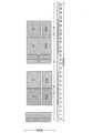
様々な実施形態およびモードが、RMSIをSSブロックと多重化するために利用され得る。たとえば、図3Aを参照すると、RMSI CORESET C0~C3およびRMSIデータD0~D3が、周波数分割多重(FDM)を使用して、1つまたは複数のSSブロックSSB0~SSB3と多重化されてもよい。図3Aの例では、特定のRMSIに対するRMSI coresetとRMSIデータの各ペアが、それぞれ特定のSSブロックと周波数領域において多重化されてもよい。このように、RMSI CORESETとデータのペアは、それの対応するSSブロックに対して固定位置を有し、SSブロックの周期に対応するデフォルト周期を有することができる。 Various embodiments and modes may be utilized to multiplex RMSI with SS blocks. For example, referring to FIG. 3A, RMSI CORESETs C0-C3 and RMSI data D0-D3 may be multiplexed with one or more SS blocks SSB0-SSB3 using frequency division multiplexing (FDM). In the example of FIG. 3A, each pair of RMSI coreset and RMSI data for a specific RMSI may be multiplexed with a respective specific SS block in the frequency domain. In this way, an RMSI CORESET and data pair can have a fixed position with respect to its corresponding SS block and a default period that corresponds to the period of the SS block.
図3Bを参照すると、別の例が、RMSI CORESETC0~C3がSSブロックSSB0~SSB3と時分割多重化(TDM化)されるが、同じスロット内にあるIntraSlotTDMモードを示している。図のように、RMSIデータD0~D3の多重化は、PBCHによりシグナリングされないが、代わりにRMSI CORESET C0~C3においてPDCCHグラントによりシグナリングされる。この例では、RMSIデータD0~D3は、SSブロックSSB0~SSB3とFDM化される。RMSI CORESET C0~C3は、SSブロックSSB0~SSB3とRMSIデータD0~D3のいずれかまたは両方の周波数帯域に対応する周波数帯域にあってもよい。図3Bは、RMSI CORESET C0~C3がSSブロックSSB0~SSB3とRMSIデータD0~D3の両方の周波数帯域に対応する周波数帯域にある例を示す。 Referring to FIG. 3B, another example shows an IntraSlot TDM mode in which RMSI CORESETC0-C3 are time division multiplexed (TDMed) with SS blocks SSB0-SSB3, but within the same slot. As shown, the multiplexing of RMSI data D0-D3 is not signaled by PBCH, but instead by PDCCH grants in RMSI CORESET C0-C3. In this example, RMSI data D0 to D3 are FDMed into SS blocks SSB0 to SSB3. RMSI CORESET C0 to C3 may be in a frequency band corresponding to one or both of the frequency bands of SS blocks SSB0 to SSB3 and RMSI data D0 to D3. FIG. 3B shows an example in which RMSI CORESET C0-C3 is in a frequency band corresponding to the frequency band of both SS blocks SSB0-SSB3 and RMSI data D0-D3.
図3Cを参照すると、また別の例が、RMSI CORESET C0~C3がSSブロックとTDM化されるが、異なる1つまたは複数のスロットにあるTDMモードを示している。たとえば、基地局がSSブロックに対して現在便利な位置にRMSIを配置できるようにするために、設定可能なモニタリングウィンドウが使用されてもよい。その上、そのようなTDMモードまたは同様のタイプのTDMモードでは、周期および/またはモニタリングウィンドウ継続時間は設定可能であってもよい。また、このタイプのTDMモードまたは同様のタイプのTDMモードは、100MHzなど、所与のしきい値を下回る帯域幅を有するシステムにおいて有利であり得る。 Referring to FIG. 3C, yet another example illustrates a TDM mode in which RMSI CORESETs C0-C3 are TDMed with SS blocks, but in different slots or slots. For example, a configurable monitoring window may be used to allow the base station to place the RMSI in a currently convenient location relative to the SS block. Moreover, in such a TDM mode or a similar type of TDM mode, the periodicity and/or monitoring window duration may be configurable. Also, this type of TDM mode or a similar type of TDM mode may be advantageous in systems with bandwidth below a given threshold, such as 100MHz.
上述のように、利用可能な帯域幅または所望の動作特性など、様々な要因に応じて、異なる多重化モードが、より有利であるまたはあまり有利ではない場合がある。したがって、基地局が、必要なときに多重化モードを構成する能力を必要とし得る。これに関連して生じる問題は、UEがどのようにして多重化モードを決定し、したがって通信ネットワーク(システムと呼ばれることがある)にアクセスするために必要であるRMSIを正常に検出し、処理し得るかということである。 As discussed above, different multiplexing modes may be more or less advantageous depending on various factors, such as available bandwidth or desired operating characteristics. Therefore, a base station may require the ability to configure multiplexing modes when needed. The question that arises in this regard is how the UE determines the multiplexing mode and therefore successfully detects and processes the RMSI required to access the communication network (sometimes referred to as the system). It's about whether you get it.
本明細書で説明する実施形態は、そのような課題に様々な方法で対処することができる。たとえば、例示的な解決策は、様々な多重化シナリオに対するアカウントへのシグナリングおよび/または制御のために構成された通信構成要素を提供することを含むことができる。特定の例として、基地局が、インジケータを使用することによってUEにモードおよび周期をシグナリングすることができる。インジケータは、PBCHのMIBにおいて提供されるフィールドであってもよい。MIBリソースの消費を減少させるために、インジケータは、ジョイントコーディングされたNビットインジケータ(たとえば、N=2または3)であってもよい。ジョイントコーディングのシナリオは、各2また3ビット値で、多重化モードおよび周期を含む能力を含んでもよい。別の例として、周期は、FDMの場合はデフォルト値、TDMの場合はいくつかの設定可能な周期のうちの1つであってもよい。他の例では、周期はそれぞれ、20ミリ秒など、複数の基地局周期であってもよい。2ビットフィールドの場合のジョイントコーディングの一例を、以下の表1に示す。追加または代替の周期および/またはモニタリングウィンドウ継続時間が、Nビットインジケータを使用してジョイントコーディングによってシグナリングされてもよい。 Embodiments described herein may address such issues in a variety of ways. For example, example solutions may include providing communication components configured for signaling and/or control to account for various multiplexing scenarios. As a particular example, a base station can signal the mode and period to the UE by using indicators. The indicator may be a field provided in the MIB of the PBCH. To reduce MIB resource consumption, the indicator may be a jointly coded N-bit indicator (eg, N=2 or 3). Joint coding scenarios may include the ability to include multiplexing modes and periods in each 2 or 3 bit value. As another example, the period may be a default value for FDM or one of several configurable periods for TDM. In other examples, the periods may be multiple base station periods, such as 20 milliseconds each. An example of joint coding for a 2-bit field is shown in Table 1 below. Additional or alternative periods and/or monitoring window durations may be signaled by joint coding using N-bit indicators.

次に図4Aを参照すると、ベースバンドプロセッサまたはBSコントローラなどの基地局プロセッサのためのワイヤレス通信の方法が、ブロック400Aにおいて始まり得る。ブロック400Aにおいて、基地局は、残存最小システム情報(RMSI)の送信に対して、多重化のタイプおよび周期を決定してもよい。また基地局は、インジケータに基づいて、設定可能なモニタリングウィンドウの継続時間を決定してもよい。上記のように、多重化のタイプは、RMSIを同期信号(SS)ブロックと多重化するためのものである。追加または代替として、基地局は、SSブロックと多重化されたRMSIを送信するための利用可能な帯域幅に基づいて多重化のタイプを決定してもよい。 Referring now to FIG. 4A, a method of wireless communication for a base station processor, such as a baseband processor or BS controller, may begin at
ブロック400Aにおいて基地局によって行われる決定は、いくつかの結果のうちの1つを有し得る。たとえば、基地局は、多重化のタイプがFDMであり、周期がSSブロックの周期に対応するデフォルト周期であると決定し得る。代替または追加として、基地局は、多重化のタイプがTDMであり、周期が設定可能な周期であると決定し得る。さらに、基地局は、周期が2つ以上の所定の周期のうちの1つである、または所定の値のセットの間の設定可能な周期であると決定し得る。基地局は、SSブロックと多重化されたRMSIを送信するための利用可能な帯域幅に基づいて、ブロック400Aにおいて決定を行ってもよい。処理は、ブロック400Aからブロック402Aに進み得る。 The decision made by the base station at
ブロック402Aにおいて、基地局は、多重化のタイプおよび周期をシグナリングするインジケータを生成してもよい。たとえば、基地局は、モニタリングウィンドウの決定された継続時間をシグナリングするためのインジケータを生成してもよい。代替または追加として、基地局は、PBCHのMIBに1つまたは複数のビットを設定することによってインジケータを生成してもよい。代替または追加として、基地局は、ジョイントコーディングされたインジケータとしてインジケータを生成してもよい。 At
図4Bを参照すると、電気通信プロセッサまたはBSコントローラなどの基地局プロセッサのためのワイヤレス通信の別の方法が、ブロック400Bにおいて始まり、ブロック402Bに進んでもよく、基地局は、ブロック400Aおよびブロック402Aに関して上記で説明した動作と同様の動作を行ってもよい。しかしながら、処理はブロック402Bからブロック404Bに進んでもよく、基地局はインジケータをブロードキャストしてもよい。たとえば、基地局は、ブロック400Bにおいて決定された多重化モードおよび周期に従ってPBCHで、ブロック402Bにおいて生成されたインジケータをSSブロックと多重化してもよい。したがって、インジケータは、PBCHのMIBにおいてブロードキャストされ得る。また、ブロック406Bにおいて、基地局は、SSブロックと多重化されたRMSIの送信をブロードキャストしてもよい。 Referring to FIG. 4B, another method of wireless communication for a base station processor, such as a telecommunications processor or a BS controller, may begin at
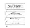
次に図5Aを参照すると、ベースバンドプロセッサまたはUEコントローラなどのUEプロセッサのためのワイヤレス通信の方法が、ブロック502Aにおいて始まり得る。ブロック502Aにおいて、UEは、基地局によるRMSIの送信に対して、多重化のタイプおよび周期をシグナリングするインジケータを識別してもよい。たとえば、UEは、インジケータを含むデータを含んだ送信を受信していてもよい。したがって、UEは、送信のデータをメモリに記憶していてもよい。このようにUEは、メモリに記憶されたデータを分析し、データ内の所定の場所のインジケータを認識することによって、または基準値に対してインジケータを識別してもよい。上述のように、多重化のタイプは、同期信号SSブロックとRMSIを多重化するためのものである。いくつかの態様では、UEは、RMSIのためのモニタリングウィンドウの継続時間をシグナリングするインジケータを識別してもよい。代替または追加として、UEは、PBCHのMIB内の1つまたは複数のビットとしてインジケータを識別してもよい。代替または追加として、UEは、上記のように、ジョイントコーディングされたインジケータとしてインジケータを識別してもよい。処理は、ブロック502Aからブロック504Aに進み得る。 Referring now to FIG. 5A, a method of wireless communication for a UE processor, such as a baseband processor or UE controller, may begin at
ブロック504Aにおいて、UEは、インジケータに基づいて多重化のタイプおよび周期を決定してもよい。たとえば、UEは、多重化のタイプがFDMであり、周期がSSブロックの周期に対応するデフォルト周期であると決定し得る。代替または追加として、UEは、多重化のタイプが時分割多重(TDM)であり、周期が設定可能な周期であると決定し得る。たとえば、UEは、周期が2つ以上の所定の周期のうちの1つである、または所定の値のセットの間の設定可能な周期であると決定し得る。処理は、ブロック504Aからブロック508Aに進み得る。 At
ブロック508Aにおいて、UEは、多重化のタイプおよび周期に基づいてRMSIの次の送信を処理してもよい。サンプルタイプは、デフォルト周期のFDM、20ms周期のTDM、40ms周期のTDM、および80ms周期のTDMを含む。また、UEは、さらに継続時間に基づいてRMSIの次の送信を処理してもよい。 At
図5Bを参照すると、電気通信プロセッサなどのUEプロセッサのためのワイヤレス通信の別の方法が、ブロック502B、504B、および508Bを含んでもよく、基地局は、ブロック502A、504A、および508Aに関して上記で説明した動作と同様の動作を行ってもよい。しかしながら、処理はブロック500Bから始まってもよく、UEはインジケータを受信してもよい。たとえば、UEは、上記のように、インジケータを含んだMIBを有するPBCHを受信してもよい。処理は、ブロック500Bからブロック502Bに進み得る。 Referring to FIG. 5B, another method of wireless communication for a UE processor, such as a telecommunications processor, may include
また処理は、ブロック504Bからブロック506Bに進んでもよく、UEは送信を受信してもよい。たとえば、UEは、インジケータが含まれているMIBを有するPBCHで送信を受信してもよい。処理は、ブロック506Bからブロック508Bに進み得る。 Processing may also proceed from
次に図6を参照すると、NR-SS基地局105(図2参照)などの基地局600が、上記のように、コントローラ/プロセッサ240と、メモリ242と、アンテナ234a~234tとを有してもよい。基地局600はまた、図2に関して上記でも説明した追加の構成要素を備えるワイヤレス無線601a~601tを有してもよい。基地局600のメモリ242は、図4Aおよび図4Bにおいて上記で説明したように手順を行うためにプロセッサ/コントローラ240を設定するアルゴリズムを記憶する。 Referring now to FIG. 6, a
メモリ242によって記憶されたアルゴリズムが、前に説明したように、RMSI多重化タイプおよび周期のインジケータに関係する動作を行うためにプロセッサ/コントローラ240を設定する。たとえば、RMSI多重化モードおよび周期セレクタ602が、前に説明したように多重化モードおよび周期を決定することを含む動作を行うためにコントローラプロセッサ240を設定する。その上、インジケータ生成器603が、前に説明した任意の方法でインジケータを生成することを含む動作を行うためにコントローラプロセッサ240を設定する。さらに、インジケータ送信機604が、前に説明した任意の方法でインジケータを送信することを含む動作を行うためにコントローラプロセッサ240を設定する。また、RMSI送信機605が、前に説明したようにRMSIを送信することを含む動作を行うためにコントローラプロセッサ240を設定する。 An algorithm stored by
次に図7を参照すると、UE115(図2参照)などのUE700が、上記のように、コントローラ/プロセッサ280と、メモリ282と、アンテナ252a~252rとを有してもよい。UE700はまた、図2に関して上記でも説明した追加の構成要素を備えるワイヤレス無線701a~701rを有してもよい。UE700のメモリ282は、図5Aおよび図5Bにおいて上記で説明したように手順を行うためにプロセッサ/コントローラ280を設定するアルゴリズムを記憶する。 Referring now to FIG. 7, a
メモリ282によって記憶されたアルゴリズムが、前に説明したように、UE700によるRMSIインジケータの使用に関係する手順を行うためにプロセッサ/コントローラ280を設定する。たとえば、インジケータ受信機702が、前に説明した任意の方法でインジケータを受信することを含む動作を行うためにコントローラプロセッサ280を設定する。その上、インジケータ識別子703が、前に説明した任意の方法でインジケータを識別することを含む動作を行うためにコントローラプロセッサ280を設定する。また、RMSI多重化モード決定器704が、多重化のタイプおよび周期を決定することを含む動作を行うためにコントローラプロセッサ280を設定する。さらに、RMSI受信機705が、前に説明した任意の方法でRMSIを受信することを含む動作を行うためにコントローラプロセッサ280を設定する。またさらに、RMSIプロセッサ706が、前に説明した任意の方法で次の送信を処理することを含む動作を行うためにコントローラプロセッサ280を設定する。 Algorithms stored by
情報および信号は、多種多様な技術および技法のいずれかを使用して表されてもよいことを、当業者は理解するであろう。たとえば、上記の説明全体にわたって参照される場合があるデータ、命令、コマンド、情報、信号、ビット、シンボル、およびチップは、電圧、電流、電磁波、磁場もしくは粒子、光場もしくは光粒子、またはそれらの任意の組合せによって表されてもよい。 Those of skill in the art would understand that information and signals may be represented using any of a variety of different technologies and techniques. For example, data, instructions, commands, information, signals, bits, symbols, and chips that may be referenced throughout the above description refer to voltages, electrical currents, electromagnetic waves, magnetic fields or particles, light fields or particles, or May be represented by any combination.
本明細書で説明する機能ブロックおよびモジュール(たとえば、図2、図4A、図4B、図5A、図5B、図6および図7の機能ブロックおよびモジュール)は、プロセッサ、電子デバイス、ハードウェアデバイス、電子構成要素、論理回路、メモリ、ソフトウェアコード、ファームウェアコードなど、またはそれらの任意の組合せを備え得る。 The functional blocks and modules described herein (e.g., the functional blocks and modules of FIGS. 2, 4A, 4B, 5A, 5B, 6 and 7) may include processors, electronic devices, hardware devices, It may include electronic components, logic circuits, memory, software code, firmware code, etc., or any combination thereof.
本明細書で本開示に関連して説明した様々な例示的論理ブロック、モジュール、回路、およびアルゴリズムステップが、電子ハードウェア、コンピュータソフトウェア、または両方の組合せとして実装され得ることを当業者ならさらに理解されよう。ハードウェアとソフトウェアとのこの互換性を明確に示すために、様々な例示的な構成要素、ブロック、モジュール、回路、およびステップについて、上記では概してそれらの機能に関して説明した。そのような機能が、ハードウェアとして実現されるか、ソフトウェアとして実現されるかは、特定の適用例と、システム全体に課される設計制約とによって決まる。当業者は説明した機能を特定の適用例ごとに様々な方法で実装してもよいが、そのような実装の決定は、本開示の範囲からの逸脱を引き起こすものと解釈されるべきでない。当業者はまた、本明細書で説明する構成要素、方法、または相互作用の順序または組合せは例にすぎないこと、および、本開示の様々な態様の構成要素、方法、または相互作用は、本明細書で図示および説明する方法とは異なる方法において組み合わされるか、または実行される場合があることを容易に認識されよう。 Those skilled in the art will further understand that the various example logic blocks, modules, circuits, and algorithmic steps described herein in connection with the present disclosure may be implemented as electronic hardware, computer software, or a combination of both. It will be. To clearly illustrate this compatibility between hardware and software, various example components, blocks, modules, circuits, and steps have been described above generally in terms of their functionality. Whether such functionality is implemented as hardware or software depends on the particular application and design constraints imposed on the overall system. Those skilled in the art may implement the described functionality in various ways for each particular application, and such implementation decisions should not be construed as causing a departure from the scope of this disclosure. Those skilled in the art will also appreciate that the orders or combinations of components, methods, or interactions described herein are only examples, and that the components, methods, or interactions of various aspects of this disclosure are It will be readily appreciated that the features may be combined or performed in ways different from those shown and described in the specification.
本明細書の開示と関連して説明する様々な例示的論理ブロック、モジュール、および回路は、汎用プロセッサ、デジタルシグナルプロセッサ(DSP)、特定用途用集積回路(ASIC)、フィールドプログラマブルゲートアレイ(FPGA:field programmable gate array)もしくは他のプログラマブルロジックデバイス(programmable logic device)、個別のゲートもしくはトランジスタロジック、個別のハードウェア構成要素、または、本明細書で説明した機能を行うように設計された、これらの任意の組合せで、実装または実行され得る。汎用プロセッサはマイクロプロセッサであってもよいが、代替として、プロセッサは任意の従来のプロセッサ、コントローラ、マイクロコントローラ、またはステートマシーンであってもよい。プロセッサはまた、コンピューティングデバイスの組合せ、たとえば、DSPおよびマイクロプロセッサの組合せ、複数のマイクロプロセッサ、DSPコアと連携する1つもしくは複数のマイクロプロセッサ、または任意の他のそのような構成、として実装されてもよい。 Various example logic blocks, modules, and circuits described in connection with the disclosure herein include general purpose processors, digital signal processors (DSPs), application specific integrated circuits (ASICs), field programmable gate arrays (FPGAs), field programmable gate array or other programmable logic device, discrete gate or transistor logic, discrete hardware components, or other programmable logic devices designed to perform the functions described herein. Any combination may be implemented or performed. A general purpose processor may be a microprocessor, but in the alternative, the processor may be any conventional processor, controller, microcontroller, or state machine. A processor may also be implemented as a combination of computing devices, such as a combination of a DSP and a microprocessor, multiple microprocessors, one or more microprocessors in conjunction with a DSP core, or any other such configuration. It's okay.
本明細書の開示と関連して記載した方法またはアルゴリズムのステップは、直接ハードウェアで、プロセッサで実行されるソフトウェアモジュールで、またはこの2つの組合せで、具体化され得る。ソフトウェアモジュールは、RAMメモリ、フラッシュメモリ、ROMメモリ、EPROMメモリ、EEPROMメモリ、レジスタ、ハードディスク、リムーバブルディスク、CD-ROM、または当技術分野において知られている任意の他の形態の記憶媒体に存在する場合がある。例示的な記憶媒体は、プロセッサが記憶媒体から情報を読み取ること、および記憶媒体に情報を書き込むことができるように、プロセッサに結合される。代替として、記憶媒体は、プロセッサと一体化してよい。プロセッサおよび記憶媒体は、ASICの中に存在する場合がある。ASICはユーザ端末に存在する場合がある。代替として、プロセッサおよび記憶媒体は、個別の構成要素としてユーザ端末に存在する場合がある。 The steps of the methods or algorithms described in connection with the disclosure herein may be embodied directly in hardware, in a software module running on a processor, or in a combination of the two. A software module resides in RAM memory, flash memory, ROM memory, EPROM memory, EEPROM memory, registers, hard disk, removable disk, CD-ROM, or any other form of storage medium known in the art. There are cases. An exemplary storage medium is coupled to the processor such that the processor can read information from, and write information to, the storage medium. In the alternative, the storage medium may be integral to the processor. The processor and storage medium may reside within an ASIC. ASICs may reside in user terminals. In the alternative, the processor and the storage medium may reside as separate components in a user terminal.
1つまたは複数の例示的設計では、記載した機能は、ハードウェア、ソフトウェア、ファームウェア、またはこれらの任意の組合せで実装され得る。ソフトウェアで実装される場合、機能は、1つまたは複数の命令またはコードとしてコンピュータ可読媒体上に記憶され得るか、またはコンピュータ可読媒体を介して送信され得る。コンピュータ可読媒体は、コンピュータ記憶媒体と、ある場所から別の場所へのコンピュータプログラムの転送を容易にする任意の媒体を含む通信媒体の両方を含む。コンピュータ可読記憶媒体は、汎用または専用コンピュータによってアクセスされ得る任意の利用可能な媒体であり得る。限定ではなく例として、そのようなコンピュータ可読媒体は、RAM、ROM、EEPROM、CD-ROMもしくは他の光ディスクストレージ、磁気ディスクストレージもしくは他の磁気ストレージデバイス、あるいは命令もしくはデータ構造の形態の所望のプログラムコード手段を搬送もしくは記憶するために使用され得、汎用もしくは専用コンピュータ、または汎用もしくは専用プロセッサによってアクセスされ得る任意の他の媒体を備えることができる。また、接続は、コンピュータ可読媒体と適切に呼ばれる場合がある。たとえば、ソフトウェアが、同軸ケーブル、光ファイバケーブル、ツイストペア、またはデジタル加入者回線(DSL)を使用して、ウェブサイト、サーバ、または他のリモートソースから送信される場合、同軸ケーブル、光ファイバケーブル、ツイストペア、またはDSLは、媒体の定義に含まれる。本明細書で使用するディスク(disk)およびディスク(disc)は、コンパクトディスク(disc)(CD)、レーザーディスク(登録商標)(disc)、光ディスク(disc)、デジタル多用途ディスク(disc)(DVD)、ハードディスク(disk)、ソリッドステートディスク(disk)、およびBlu-ray(登録商標)ディスク(disc)を含み、ディスク(disk)は通常、データを磁気的に再生し、ディスク(disc)は、レーザーを用いてデータを光学的に再生する。上記の組合せもまた、コンピュータ可読媒体の範囲内に含まれるべきである。 In one or more example designs, the described functionality may be implemented in hardware, software, firmware, or any combination thereof. If implemented in software, the functions may be stored on or transmitted over as one or more instructions or code on a computer-readable medium. Computer-readable media includes both computer storage media and communication media including any medium that facilitates transfer of a computer program from one place to another. Computer-readable storage media can be any available media that can be accessed by a general purpose or special purpose computer. By way of example and not limitation, such computer readable medium may include RAM, ROM, EEPROM, CD-ROM or other optical disk storage, magnetic disk storage or other magnetic storage device, or the desired program in the form of instructions or data structures. It may comprise any other medium that can be used to carry or store code means and that can be accessed by a general purpose or special purpose computer or processor. A connection may also be properly referred to as a computer-readable medium. For example, if the software is transmitted from a website, server, or other remote source using coaxial cable, fiber optic cable, twisted pair, or digital subscriber line (DSL), coaxial cable, fiber optic cable, Twisted pair, or DSL, is included in the definition of media. As used herein, "disk" and "disc" refer to compact disc (disc) (CD), Laserdisc (registered trademark) (disc), optical disc (disc), digital versatile disc (disc) (DVD). ), hard disks (disks), solid-state disks (disks), and Blu-ray (registered trademark) disks (discs); disks typically reproduce data magnetically; Data is optically reproduced using a laser. Combinations of the above should also be included within the scope of computer-readable media.
特許請求の範囲内を含めて、本明細書で使用する場合、「および/または」という用語は、2つ以上の項目のリストにおいて使用されるとき、列挙される項目のうちのいずれか1つが単独で用いられ得ること、または列挙される項目のうちの2つ以上の任意の組合せが用いられ得ることを意味する。たとえば、組成物が構成要素A、B、および/またはCを含むものとして説明される場合、組成物は、Aのみ、Bのみ、Cのみ、AとBの組合せ、AとCの組合せ、BとCの組合せ、またはAとBとCの組合せを含むことができる。また、特許請求の範囲内を含む本明細書で使用する「のうちの少なくとも1つ」で終わる項目の列挙において使用される「または」は、たとえば、「A、B、またはCのうちの少なくとも1つ」という列挙が、AまたはBまたはCまたはABまたはACまたはBCまたはABC(すなわち、AおよびBおよびC)、あるいはそれらの任意の組合せにおけるこれらのいずれかを意味するような、選言的な列挙を示す。
本開示の以上の説明は、いかなる当業者も本開示を作成または使用することが可能となるように提供される。本開示の様々な変更が当業者に容易に明らかになり、本明細書で定義する一般原理は、本開示の趣旨または範囲から逸脱することなく他の変形形態に適用されてもよい。したがって、本開示は、本明細書で説明した例および設計に限定されるものでなく、本明細書で開示した原理および新規の特徴と一致する最も広い範囲を与えられるべきである。As used herein, including in the claims, the term "and/or" when used in a list of two or more items means that any one of the listed items Means that it can be used alone or in any combination of two or more of the listed items. For example, if a composition is described as including components A, B, and/or C, the composition may include A only, B only, C only, a combination of A and B, a combination of A and C, B and C, or A, B, and C. Also, as used herein, including in the claims, "or" used in the enumeration of items ending with "at least one of" means, for example, "at least one of A, B, or C." disjunctive, such that the enumeration "one" means A or B or C or AB or AC or BC or ABC (i.e. A and B and C), or any of these in any combination thereof; Shows a list of enumerations.
The previous description of the disclosure is provided to enable any person skilled in the art to make or use the disclosure. Various modifications of this disclosure will be readily apparent to those skilled in the art, and the general principles defined herein may be applied to other variations without departing from the spirit or scope of this disclosure. Therefore, this disclosure is not limited to the examples and designs described herein, but is to be accorded the widest scope consistent with the principles and novel features disclosed herein.
100 ワイヤレスネットワーク
105 gNB、基地局
110a~c マクロセル
110x~z スモールセル
115 ユーザ機器(UE)
125 通信リンク
134 バックホール通信
212 データソース
220 送信プロセッサ
230 送信(TX)多入力多出力(MIMO)プロセッサ
232 変調器(MOD)
234 アンテナ
236 MIMO検出器
238 受信プロセッサ
239 データシンク
240 コントローラ/プロセッサ
242 メモリ
244 スケジューラ
252 アンテナ
254 復調器(DEMOD)
256 MIMO検出器
258 受信プロセッサ
260 データシンク
262 データソース
264 送信プロセッサ
266 TX MIMOプロセッサ
280 コントローラ/プロセッサ
282 メモリ
600 基地局
601 ワイヤレス無線
602 RMSI多重化モードおよび周期セレクタ
603 インジケータ生成器
604 インジケータ送信機
605 RMSI送信機
700 UE
701 ワイヤレス無線
702 インジケータ受信機
703 インジケータ識別子
704 RMSI多重化モード決定器
705 RMSI受信機
706 RMSIプロセッサ100 wireless networks
105 gNB, base station
110a-c macrocell
110x~z small cell
115 User Equipment (UE)
125 Communication Link
134 Backhaul communication
212 Data Source
220 transmit processor
230 Transmission (TX) Multiple Input Multiple Output (MIMO) Processor
232 Modulator (MOD)
234 Antenna
236 MIMO detector
238 Receive Processor
239 Data Sink
240 controller/processor
242 memory
244 Scheduler
252 Antenna
254 Demodulator (DEMOD)
256 MIMO detector
258 Receive Processor
260 data sink
262 data sources
264 Transmit Processor
266TX MIMO processor
280 controller/processor
282 Memory
600 base stations
601 wireless radio
602 RMSI Multiplexing Mode and Period Selector
603 indicator generator
604 indicator transmitter
605 RMSI transmitter
700 U.E.
701 wireless radio
702 indicator receiver
703 indicator identifier
704 RMSI Multiplexing Mode Determiner
705 RMSI receiver
706 RMSI processor
Claims (16)
Translated fromJapanese残存最小システム情報(RMSI)の送信に対して多重化のタイプおよび周期をシグナリングする、受信されたインジケータを、ユーザ機器(UE)によって識別するステップであって、
多重化の前記タイプが、前記RMSIを同期信号(SS)ブロックと多重化するためのものであり、
前記インジケータは、マスタ情報ブロック(MIB)内の1つまたは複数のビットとして識別され、
ジョイントエンコーディングされた1つまたは複数のビットが前記RMSIの前記送信の多重化の前記タイプおよび前記周期の両方を直接示すように、前記RMSIの前記送信の多重化の前記タイプおよび前記周期は、前記MIB内の前記1つまたは複数のビットでジョイントコーディングされる、ステップと、
前記インジケータに基づいて多重化の前記タイプおよび前記周期を前記UEによって決定するステップと、
多重化の前記タイプに基づいて前記RMSIの前記送信を前記UEによって処理するステップと
を含む、方法。A method of wireless communication, the method comprising:
identifying, by user equipment (UE), areceived indicator that signals the type and periodicity of multiplexing for transmission ofminimum remaining system information (RMSI);
the type of multiplexing is for multiplexing the RMSI with a synchronization signal (SS) block;
the indicator isidentified asone or more bits withina master information block (MIB);
The type and the period of multiplexing of the transmission of the RMSI are such that the joint encoded bit or bits directly indicate both the type of multiplexing and the period of the transmission of the RMSI. jointly coded with the one or more bits in the MIB ;
determining by the UE the type of multiplexing and the periodicity based on the indicator;
processing the transmission of theRMSI by the UE based onthe type of multiplexing.
多重化の前記タイプが時分割多重(TDM)であって、前記周期が設定可能な周期であると決定するステップ
を含む、請求項1に記載の方法。determining that said type of multiplexing is Frequency Division Multiplexing (FDM) and said period is a default period corresponding to the period of said SS block; and/or said type of multiplexing is Time Division Multiplexing (TDM); 2. The method of claim 1, comprising: ) determining that the period is a configurable period.
前記UEによって、さらに前記継続時間に基づいてRMSIの次の送信を処理するステップをさらに含む、請求項1に記載の方法。identifying the indicator that signals a duration of a monitoring window for the RMSI;
2. The method of claim 1, further comprising processing a subsequent transmission of an RMSI by the UE further based on the duration.
少なくとも1つのプロセッサと、
前記少なくとも1つのプロセッサに結合された少なくとも1つのメモリと
を備え、前記少なくとも1つのプロセッサが、
残存最小システム情報(RMSI)の送信に対して多重化のタイプおよび周期をシグナリングする、受信されたインジケータを、前記UEによって識別することであって、
多重化の前記タイプが、前記RMSIを同期信号(SS)ブロックと多重化するためのものであり、
前記インジケータは、マスタ情報ブロック(MIB)内の1つまたは複数のビットとして識別され、
ジョイントエンコーディングされた1つまたは複数のビットが前記RMSIの前記送信の多重化の前記タイプおよび前記周期の両方を直接示すように、前記RMSIの前記送信の多重化の前記タイプおよび前記周期は、前記MIB内の前記1つまたは複数のビットでジョイントコーディングされる、識別することと、
前記インジケータに基づいて多重化の前記タイプおよび前記周期を前記UEによって決定することと、
多重化の前記タイプに基づいて前記RMSIの前記送信を前記UEによって処理することと
を行うように構成される、UE。User equipment (UE),
at least one processor;
at least one memory coupled to the at least one processor, the at least one processor comprising:
identifying, by the UE, a received indicator signaling a type and periodicity of multiplexing for transmission ofminimum remaining system information (RMSI);
the type of multiplexing is for multiplexing the RMSI with a synchronization signal (SS) block;
the indicator isidentified asone or more bits withina master information block (MIB);
The type and the period of multiplexing of the transmission of the RMSI are such that the joint encoded bit or bits directly indicate both the type of multiplexing and the period of the transmission of the RMSI. jointly coded with the one or more bits in the MIB ;
determining by the UE the type of multiplexing and theperiodicity based on the indicator;
and processing by the UE thetransmissionof theRMSI based onthe type of multiplexing.
多重化の前記タイプが周波数分割多重(FDM)であって、前記周期が前記SSブロックの周期に対応するデフォルト周期である、または
多重化の前記タイプが時分割多重(TDM)であって、前記周期が設定可能な周期である
のうちの少なくとも一方であると決定するように構成される、請求項5に記載のUE。the at least one processor,
said type of multiplexing is frequency division multiplexing (FDM) and said period is a default period corresponding to the period of said SS block; or said type of multiplexing is time division multiplexing (TDM) and said period is a default period corresponding to the period of said SS block; 6. The UE of claim 5, configured to determine that the period is at least one of a configurable period.
前記RMSIのためのモニタリングウィンドウの継続時間をシグナリングする前記インジケータを識別するように構成され、
前記少なくとも1つのプロセッサが、
前記UEによって、さらに前記継続時間に基づいてRMSIの次の送信を処理するようにさらに構成される、請求項5に記載のUE。the at least one processor,
configured to identify the indicator that signals a duration of a monitoring window for the RMSI;
the at least one processor,
6. The UE of claim 5, further configured by the UE to processa next transmission of an RMSI further based on the duration.
基地局によって、残存最小システム情報(RMSI)の送信に対して、多重化のタイプおよび周期を決定するステップであって、
多重化の前記タイプが、前記RMSIを同期信号(SS)ブロックと多重化するためのものである、ステップと、
前記基地局によって、前記RMSIの前記送信のための多重化の前記タイプおよび前記周期をシグナリングするインジケータを生成するステップであって、
前記インジケータは、物理ブロードキャストチャネル(PBCH)のマスタ情報ブロック(MIB)内の1つまたは複数のビットを設定することによって生成され、
ジョイントエンコーディングされた1つまたは複数のビットが前記RMSIの前記送信の多重化の前記タイプおよび前記周期の両方を直接示すように、前記RMSIの前記送信の多重化の前記タイプおよび前記周期は、前記1つまたは複数のビットでジョイントコーディングされる、ステップと
を含む、方法。A method of wireless communication, the method comprising:
determining, by the base station, a multiplexing type and periodicity for transmission of minimum remaining system information (RMSI), the step of:
the type of multiplexing is for multiplexing the RMSI with a synchronization signal (SS) block;
generating, by the base station, an indicator signaling the type of multiplexing and the periodicityfor the transmission of the RMSI ;
the indicator isgenerated by settingone or more bits in a master information block (MIB) of a physical broadcast channel (PBCH);
The type and the period of multiplexing of the transmission of the RMSI are such that the joint encoded bit or bits directly indicate both the type of multiplexing and the period of the transmission of the RMSI. A method comprisingjointly coding one or more bits .
多重化の前記タイプが時分割多重(TDM)であって、前記周期が設定可能な周期であると決定するステップ
を含む、請求項9に記載の方法。determining that said type of multiplexing is Frequency Division Multiplexing (FDM) and said period is a default period corresponding to the period of said SS block; and/or said type of multiplexing is Time Division Multiplexing (TDM); 10. The method of claim 9, comprising determining that the period is a configurable period.
前記継続時間をシグナリングするために前記インジケータを生成するステップと
をさらに含む、請求項9に記載の方法。determining a duration of a monitoring window for said RMSI;
10. The method of claim 9, further comprising: generating the indicator to signal the duration.
少なくとも1つのプロセッサと、
前記少なくとも1つのプロセッサに結合された少なくとも1つのメモリと
を備え、前記少なくとも1つのプロセッサが、
前記基地局によって、残存最小システム情報(RMSI)の送信に対して、多重化のタイプおよび周期を決定することであって、
多重化の前記タイプが、前記RMSIを同期信号(SS)ブロックと多重化するためのものである、決定することと、
前記基地局によって、前記RMSIの前記送信のための多重化の前記タイプおよび前記周期をシグナリングするインジケータを生成することであって、
前記インジケータは、物理ブロードキャストチャネル(PBCH)のマスタ情報ブロック(MIB)内の1つまたは複数のビットを設定することによって生成され、
ジョイントエンコーディングされた1つまたは複数のビットが前記RMSIの前記送信の多重化の前記タイプおよび前記周期の両方を直接示すように、前記RMSIの前記送信の多重化の前記タイプおよび前記周期は、前記1つまたは複数のビットでジョイントコーディングされる、生成することと
を行うように構成される、基地局。A base station,
at least one processor;
at least one memory coupled to the at least one processor, the at least one processor comprising:
determining, by the base station, a multiplexing type and periodicity for transmission of minimum remaining system information (RMSI);
determining that the type of multiplexing is for multiplexing the RMSI with a synchronization signal (SS) block;
generating, by the base station, an indicator signaling the type of multiplexing and the periodicityfor the transmission of the RMSI ;
the indicator isgenerated by settingone or more bits in a master information block (MIB) of a physical broadcast channel (PBCH);
The type and the period of multiplexing of the transmission of the RMSI are such that the joint encoded bit or bits directly indicate both the type of multiplexing and the period of the transmission of the RMSI. A base station configured to generateand jointly code one or more bits .
多重化の前記タイプが周波数分割多重(FDM)であって、前記周期が前記SSブロックの周期に対応するデフォルト周期であると決定する、
多重化の前記タイプが時分割多重(TDM)であって、前記周期が設定可能な周期であると決定する、または
多重化の前記タイプを利用可能な帯域幅に基づいて決定する
のうちの少なくとも1つを行うように構成される、請求項13に記載の基地局。the at least one processor,
determining that the type of multiplexing is frequency division multiplexing (FDM) and that the period is a default period corresponding to the period of the SS block;
at least: determining that said type of multiplexing is time division multiplexing (TDM) and said period is a configurable period; or determining said type of multiplexing based on available bandwidth. 14. The base station of claim 13, configured to perform one of the following.
前記RMSIのためのモニタリングウィンドウの継続時間を決定することと、
前記継続時間をシグナリングするために前記インジケータを生成することと
を行うようにさらに構成される、請求項13に記載の基地局。the at least one processor,
determining a duration of a monitoring window for said RMSI;
14. The base station of claim 13, further configured to: generate the indicator to signal the duration.
Applications Claiming Priority (5)
| Application Number | Priority Date | Filing Date | Title |
|---|---|---|---|
| US201762590018P | 2017-11-22 | 2017-11-22 | |
| US62/590,018 | 2017-11-22 | ||
| US16/197,085US11362878B2 (en) | 2017-11-22 | 2018-11-20 | Radio (NR) remaining minimum system information (RMSI) multiplexing and periodicity considerations |
| US16/197,085 | 2018-11-20 | ||
| PCT/US2018/062225WO2019104151A1 (en) | 2017-11-22 | 2018-11-21 | New radio (nr) remaining minimum system information (rmsi) multiplexing and periodicity considerations |
Publications (3)
| Publication Number | Publication Date |
|---|---|
| JP2021505005A JP2021505005A (en) | 2021-02-15 |
| JP2021505005A5 JP2021505005A5 (en) | 2021-12-16 |
| JP7361690B2true JP7361690B2 (en) | 2023-10-16 |
Family
ID=66533440
Family Applications (1)
| Application Number | Title | Priority Date | Filing Date |
|---|---|---|---|
| JP2020527962AActiveJP7361690B2 (en) | 2017-11-22 | 2018-11-21 | New Radio (NR) Remaining Minimum System Information (RMSI) multiplexing and periodic considerations |
Country Status (7)
| Country | Link |
|---|---|
| US (1) | US11362878B2 (en) |
| EP (1) | EP3714571B1 (en) |
| JP (1) | JP7361690B2 (en) |
| KR (1) | KR102737838B1 (en) |
| CN (1) | CN111344986B (en) |
| SG (1) | SG11202003455SA (en) |
| WO (1) | WO2019104151A1 (en) |
Families Citing this family (4)
| Publication number | Priority date | Publication date | Assignee | Title |
|---|---|---|---|---|
| KR102403157B1 (en)* | 2018-01-02 | 2022-05-30 | 텔레호낙티에볼라게트 엘엠 에릭슨(피유비엘) | Method, network device, and terminal device for residual minimum system information |
| US20220256375A1 (en)* | 2019-07-05 | 2022-08-11 | Ntt Docomo, Inc. | Terminal |
| CN114902741B (en)* | 2019-12-31 | 2025-05-06 | 华为技术有限公司 | A method and device for transmitting system information |
| CN114365564A (en)* | 2020-08-12 | 2022-04-15 | 北京小米移动软件有限公司 | Configuration method and device of RMSI, user equipment, network equipment and storage medium |
Citations (1)
| Publication number | Priority date | Publication date | Assignee | Title |
|---|---|---|---|---|
| WO2019097633A1 (en) | 2017-11-16 | 2019-05-23 | 株式会社Nttドコモ | User terminal and wireless communication method |
Family Cites Families (10)
| Publication number | Priority date | Publication date | Assignee | Title |
|---|---|---|---|---|
| AU2002316454A1 (en)* | 2001-07-02 | 2003-01-21 | Gilat Satellite Networks, Ltd. | Method, device, and system for managing communication transmissions |
| US20100271970A1 (en)* | 2009-04-22 | 2010-10-28 | Interdigital Patent Holdings, Inc. | Method and apparatus for transmitting uplink control information for carrier aggregated spectrums |
| CN102158971B (en)* | 2010-02-11 | 2014-11-05 | 华为技术有限公司 | Method and equipment for realizing semi-persistent scheduling service or similar semi-persistent scheduling service |
| US9591644B2 (en) | 2013-08-16 | 2017-03-07 | Qualcomm Incorporated | Downlink procedures for LTE/LTE-A communication systems with unlicensed spectrum |
| JP7018059B2 (en)* | 2016-12-07 | 2022-02-09 | エルジー エレクトロニクス インコーポレイティド | Methods and devices for configuring control channels for NR in wireless communication systems |
| US10492157B2 (en)* | 2017-01-04 | 2019-11-26 | Samsung Electronics Co., Ltd. | Method and apparatus for system information delivery in advanced wireless systems |
| EP4149042B1 (en)* | 2017-05-02 | 2024-09-04 | Samsung Electronics Co., Ltd. | Method and apparatus of initial access in next generation cellular networks |
| US10715371B2 (en)* | 2017-11-01 | 2020-07-14 | Samsung Electronics Co., Ltd. | Method and apparatus of NR RMSI coreset configuration in MIB |
| US10791550B2 (en)* | 2017-11-17 | 2020-09-29 | Lg Electronics Inc. | Method of transmitting and receiving downlink channel and apparatus therefor |
| US10506588B2 (en)* | 2017-11-17 | 2019-12-10 | Lg Electronics Inc. | Method and apparatus for transmitting and receiving system information |
- 2018
- 2018-11-20USUS16/197,085patent/US11362878B2/enactiveActive
- 2018-11-21WOPCT/US2018/062225patent/WO2019104151A1/ennot_activeCeased
- 2018-11-21JPJP2020527962Apatent/JP7361690B2/enactiveActive
- 2018-11-21CNCN201880073308.5Apatent/CN111344986B/enactiveActive
- 2018-11-21EPEP18826850.2Apatent/EP3714571B1/enactiveActive
- 2018-11-21KRKR1020207014089Apatent/KR102737838B1/enactiveActive
- 2018-11-21SGSG11202003455SApatent/SG11202003455SA/enunknown
Patent Citations (1)
| Publication number | Priority date | Publication date | Assignee | Title |
|---|---|---|---|---|
| WO2019097633A1 (en) | 2017-11-16 | 2019-05-23 | 株式会社Nttドコモ | User terminal and wireless communication method |
Non-Patent Citations (4)
| Title |
|---|
| Ericsson,Summary of 7.1.2.1 Remaining details on NR-PBCH[online],TSG-RAN WG1 Meeting #90bis R1-1718789,Internet<URL:http://www.3gpp.org/ftp/tsg_ran/WG1_RL1/TSGR1_90b/Docs/R1-1718789.zip>,2017年10月09日 |
| Qualcomm Incorporated,Remaining system information delivery consideration[online],3GPP TSG RAN WG1 Meeting 90bis R1-1718528,Internet<URL:http://www.3gpp.org/ftp/tsg_ran/WG1_RL1/TSGR1_90b/Docs/R1-1718528.zip>,2017年10月03日 |
| Samsung,Remaining Details on RMSI[online],3GPP TSG RAN WG1 #91 R1-1720274,Internet<URL:http://www.3gpp.org/ftp/tsg_ran/WG1_RL1/TSGR1_91/Docs/R1-1720274.zip>,2017年11月18日 |
| vivo,Discussion on Remaining Minimum System Information[online],3GPP TSG RAN WG1 Meeting #91 R1-1719758,Internet<URL:http://www.3gpp.org/ftp/tsg_ran/WG1_RL1/TSGR1_91/Docs/R1-1719758.zip>,2017年11月18日 |
Also Published As
| Publication number | Publication date |
|---|---|
| BR112020010116A2 (en) | 2020-11-10 |
| US11362878B2 (en) | 2022-06-14 |
| JP2021505005A (en) | 2021-02-15 |
| KR102737838B1 (en) | 2024-12-03 |
| EP3714571A1 (en) | 2020-09-30 |
| CN111344986B (en) | 2022-06-28 |
| SG11202003455SA (en) | 2020-06-29 |
| KR20200086280A (en) | 2020-07-16 |
| EP3714571B1 (en) | 2022-09-07 |
| WO2019104151A1 (en) | 2019-05-31 |
| CN111344986A (en) | 2020-06-26 |
| US20190158336A1 (en) | 2019-05-23 |
Similar Documents
| Publication | Publication Date | Title |
|---|---|---|
| US11032048B2 (en) | Use-cases and constraints on multiple SRS resource sets for antenna switching in NR REL-15 | |
| JP7273900B2 (en) | CSI request procedure in LTE/LTE-A for unlicensed spectrum | |
| TWI752223B (en) | System information block providing cell access information supporting wideband coverage enhancement in wireless communication networks | |
| JP7138648B2 (en) | Controlled resource set group design for improved communication devices, systems and networks | |
| JP7384892B2 (en) | Unified synchronous channel design used in different communication modes | |
| US11088791B2 (en) | Choosing an SRS resource set when multiple sets are configured | |
| JP6692990B2 (en) | UL waveform during RACH procedure and autonomous UL transmission | |
| CN111819890A (en) | Signaling availability during a measurement window | |
| JP7361690B2 (en) | New Radio (NR) Remaining Minimum System Information (RMSI) multiplexing and periodic considerations | |
| KR20200065001A (en) | Uplink beam training | |
| JP7193528B2 (en) | Carrier switching for multi-carrier using same component of component path | |
| CN114270787B (en) | Method and device for complete configuration switching technology | |
| EP3583723B1 (en) | Future-compatible group common downlink control channel | |
| CN112913181A (en) | Supporting broadband Physical Resource Groups (PRG) in Long Term Evolution (LTE) | |
| WO2021168751A1 (en) | Techniques for coexistence of wireless communication devices that use the same frequency resources | |
| BR112020010116B1 (en) | WIRELESS COMMUNICATION METHODS, USER EQUIPMENT AND BASE STATION |
Legal Events
| Date | Code | Title | Description |
|---|---|---|---|
| A521 | Request for written amendment filed | Free format text:JAPANESE INTERMEDIATE CODE: A523 Effective date:20211101 | |
| A621 | Written request for application examination | Free format text:JAPANESE INTERMEDIATE CODE: A621 Effective date:20211101 | |
| A977 | Report on retrieval | Free format text:JAPANESE INTERMEDIATE CODE: A971007 Effective date:20221102 | |
| A131 | Notification of reasons for refusal | Free format text:JAPANESE INTERMEDIATE CODE: A131 Effective date:20221114 | |
| A521 | Request for written amendment filed | Free format text:JAPANESE INTERMEDIATE CODE: A523 Effective date:20230213 | |
| A131 | Notification of reasons for refusal | Free format text:JAPANESE INTERMEDIATE CODE: A131 Effective date:20230522 | |
| TRDD | Decision of grant or rejection written | ||
| A01 | Written decision to grant a patent or to grant a registration (utility model) | Free format text:JAPANESE INTERMEDIATE CODE: A01 Effective date:20230904 | |
| A61 | First payment of annual fees (during grant procedure) | Free format text:JAPANESE INTERMEDIATE CODE: A61 Effective date:20231003 | |
| R150 | Certificate of patent or registration of utility model | Ref document number:7361690 Country of ref document:JP Free format text:JAPANESE INTERMEDIATE CODE: R150 |