JP7361527B2 - Foldable and rotating LED tabletop mirror - Google Patents
Foldable and rotating LED tabletop mirrorDownload PDFInfo
- Publication number
- JP7361527B2 JP7361527B2JP2019145941AJP2019145941AJP7361527B2JP 7361527 B2JP7361527 B2JP 7361527B2JP 2019145941 AJP2019145941 AJP 2019145941AJP 2019145941 AJP2019145941 AJP 2019145941AJP 7361527 B2JP7361527 B2JP 7361527B2
- Authority
- JP
- Japan
- Prior art keywords
- stand
- mirror
- tabletop
- case
- base
- Prior art date
- Legal status (The legal status is an assumption and is not a legal conclusion. Google has not performed a legal analysis and makes no representation as to the accuracy of the status listed.)
- Active
Links
Images


Landscapes
- Mirrors, Picture Frames, Photograph Stands, And Related Fastening Devices (AREA)
Description
Translated fromJapaneseこの発明は折り畳み回転できる卓上三面鏡に関し、特に使用しないときにはコンパクトにして小さなスペースに収納できるようにした三面鏡に関する。 The present invention relates to a tabletop three-way mirror that can be folded and rotated, and particularly to a three-way mirror that can be made compact and stored in a small space when not in use.
例えば、女性が化粧をする場合、卓上型の三面鏡を利用することがある。この卓上三面鏡では主鏡部の両側に副鏡部を折畳み展開可能に枢支して鏡本体を構成し、鏡本体の背面にスタンドの上端部を水平軸回りに回転可能に枢支し、副鏡部を展開するとともに、鏡本体をスタンドに対して所望の角度に傾けることにより、顔や頭髪の広い範囲を鏡に写せるようになっている。 For example, when a woman puts on makeup, she may use a tabletop three-way mirror. In this tabletop three-sided mirror, the secondary mirror part is pivoted on both sides of the primary mirror part so that it can be folded and unfolded to form the mirror body, and the upper end of the stand is rotatably supported around a horizontal axis on the back of the mirror body. By unfolding the secondary mirror part and tilting the mirror main body at a desired angle with respect to the stand, a wide range of the face and hair can be reflected in the mirror.
例えば、主鏡部の背面にベースを鏡面に対して垂直な軸回りに旋回自在に取付け、スタンドの上端部に水平軸の取付けブラケットを形成する一方、ベースに軸受を一体的に形成し、スタンドの取付けブラケットの間にベースの軸受を嵌め込み、水平軸を差し込んで、ベースをスタンドの上端部を水平軸回りに回転自在に取付け、両側の副鏡部を主鏡部に対して展開するとともに、鏡本体を所望の角度に傾け、あるいは鏡本体を横長から縦長に旋回できるようにした卓上三面鏡が提案されている(特許文献1)。 For example, a base may be attached to the back of the primary mirror so that it can rotate around an axis perpendicular to the mirror surface, and a mounting bracket for the horizontal axis may be formed at the upper end of the stand. Fit the bearing of the base between the mounting brackets, insert the horizontal shaft, attach the base so that the upper end of the stand can rotate freely around the horizontal axis, and expand the secondary mirrors on both sides relative to the primary mirror. A tabletop three-sided mirror has been proposed in which the mirror body can be tilted to a desired angle or rotated from horizontal to vertical (Patent Document 1).
また、主鏡部のケースにベース及び軸受を一体的に形成し、軸受をスタンド上端部の取付けブラケットの間に嵌め込み、軸受及び取付けブラケットの軸穴に水平軸を差し込んで抜け止めすることによって、鏡本体をスタンド上端部に傾動自在に設け、旋回機能のない簡易で低コストの卓上三面鏡も提案されている(特許文献2)。 In addition, by integrally forming the base and bearing in the case of the primary mirror, fitting the bearing between the mounting brackets at the upper end of the stand, and inserting the horizontal shaft into the shaft hole of the bearing and mounting bracket to prevent it from coming off. A simple, low-cost three-sided tabletop mirror without a rotating function has also been proposed, in which the mirror body is provided tiltably at the upper end of the stand (Patent Document 2).
しかし、特許文献1、2記載の卓上三面鏡ではスタンドベースにスタンドが固定されているので、三面鏡を使用しないときにも嵩ばって収納に大きなスペースが必要であるという問題があった。 However, in the tabletop three-way mirrors described in Patent Documents 1 and 2, the stand is fixed to the stand base, so there is a problem that the three-way mirror is bulky and requires a large space for storage even when not in use.
本発明はかかる問題点に鑑み、使用しないときにはコンパクトにして小さなスペースに収納できるようにした卓上三面鏡を提供することを課題とする。 SUMMARY OF THE INVENTION In view of these problems, it is an object of the present invention to provide a tabletop three-way mirror that is compact and can be stored in a small space when not in use.
そこで、本発明に係る卓上三面鏡は、鏡本体が両側の副鏡部を主鏡部に対して開閉自在に設けて構成され、上記主鏡部及び副鏡部はケースに鏡板を嵌め込んで構成される一方、床面に置かれるベースにスタンドが立設され、該スタンド上端部にはブラケット部が形成され、該ブラケット部に上記主鏡部の背面が水平軸回りに回転可能に取付けられて上記主鏡部が傾動し得るように設けられた卓上三面鏡において、上記主鏡部のケース背面には取付けベースがケース背面に対して垂直な垂直軸回りに上記主鏡部及び副鏡部の縦姿勢と横姿勢との間で回転し得るように取付けられ、上記スタンド上端部のブラケット部はコ字状をなし、上記主鏡部のケース背面の取付けベースは上記スタンド上端部のコ字状ブラケット部に上記ケース背面の垂直軸に対して直交する水平軸回りに回転し得るように取付けられている一方、上記スタンド下端部にはコ字状ブラケット部が形成され、上記スタンドが立設されるベースには受け部が形成され、該受け部には上記スタンド下端部のコ字状ブラケット部が水平軸回りに回転自在に取付けられて上記スタンドは上記スタンドが立設されるベースに対する起立姿勢と倒伏姿勢との間で傾動し得るように設けられていることを特徴とする。Therefore, the tabletop three-sided mirror according to the present invention is configured such that the mirror main body is provided with secondary mirror parts on both sides that can be opened and closed with respect to the primary mirror part, and the primary mirror part and the secondary mirror part have mirror plates fitted into the case. On the other hand, a stand is set upright on a base placed on the floor, a bracket part is formed at the upper end of the stand, and the back surface of the primary mirror part is attached to the bracket part so as to be rotatable around a horizontal axis. In the table-top three-sided mirror provided so that the primary mirror part can be tilted, a mounting base is attached to the back of the case of the primary mirror part to rotate the primary mirror part and the secondary mirror part around a vertical axis perpendicular to the back surface of the case. The bracketat the top end of the stand has a U-shape, and the mounting baseon the back of the case of the primary mirror has a U-shapeat the top end of the stand. A U-shaped bracket is attached to the stand so that it can rotate around a horizontal axis perpendicular to the vertical axis on the back of the case, while a U-shaped bracket is formed atthe lower end of the stand,allowing the stand to stand upright. A receiving portion is formed on the base on which the standis installed , and a U-shaped bracketportionat the lower end of the stand is attached to the receiving portion so as to be rotatable around a horizontal axis, so that the standis attached to the base on which the stand is installed. It is characterized by being provided so that it can be tilted between a standing position and a lying down position.
本発明の特徴の1つはスタンドをベースに対して起立・倒伏可能に設けるようにした点にある。
これにより、三面鏡を使用するときにはベースに対してスタンドを起立させ、鏡本体を旋回させることによって、顔や頭髪の広い範囲を鏡に写すことができる。
三面鏡を使用しないときには副鏡部を主鏡部に対して折り畳み、スタンドをベースに対して倒すと、全体としてコンパクトになり、小さなスペースに収納することができる。One of the features of the present invention is that the stand is provided so that it can be raised and lowered relative to the base.
Accordingly, when using the three-way mirror, by standing the stand against the base and rotating the mirror body, a wide range of the face and hair can be reflected in the mirror.
When the three-way mirror is not in use, the secondary mirror section can be folded up against the primary mirror section, and the stand can be folded down against the base, making it compact as a whole and can be stored in a small space.
スタンド上側及び下側の水平軸の構造は特に限定されず、例えば通常の回転軸と軸受とによって構成することができるが、相互に対向する円筒部分を組合わせて水平軸を構成することもできる。 The structure of the horizontal shafts on the upper and lower sides of the stand is not particularly limited. For example, they can be constructed from a normal rotating shaft and a bearing, but the horizontal shafts can also be constructed by combining mutually opposing cylindrical parts. .
すなわち、スタンド上端のコ字状ブラケット部には円筒部分を相互に対向して突設し、主鏡部のケース背面の取付けベースには円筒部分を外側方に突設し、スタンド上端のコ字状ブラケット部の円筒部分と主鏡部のケース背面の取付けベースの円筒部分とを相互に回転自在に嵌入させることによって、スタンド上側の水平軸を構成することができる。 In other words, the U-shaped brackets at the top end of the stand have cylindrical parts protruding from each other, facing each other, and the mounting base on the back of the case of the primary mirror has cylindrical parts protruding outward. By fitting the cylindrical portion of the shaped bracket portion and the cylindrical portion of the mounting base on the back of the case of the primary mirror portion into each other so as to be rotatable, the horizontal shaft above the stand can be configured.
また、スタンド下端部のコ字状ブラケット部には円筒部分を相互に対向して突設し、ベース受け部には円筒部分を相互に外側方に突設し、スタンド上端のコ字状ブラケット部の円筒部分とベース受け部の円筒部分とを相互に回転自在に嵌入させることによって、スタンド下側の水平軸を構成することができる。 In addition, the U-shaped brackets at the bottom end of the stand have cylindrical portions that protrude opposite each other, the base receiving portions have cylindrical portions that protrude outward from each other, and the U-shaped bracket portions at the top end of the stand have cylindrical portions protruding from each other. By fitting the cylindrical portion of the stand and the cylindrical portion of the base receiving portion into each other so as to be rotatable, a horizontal shaft on the lower side of the stand can be formed.
すなわち、スタンド下側の水平軸の円筒部分の一方には円弧板部を、他方にはスタンドの縦姿勢及び横姿勢に対応する位置に突起を形成し、突起と円弧板部を競らせることによってスタンドを起立姿勢と倒伏姿勢に制動するようにしてもよい。 That is, by forming an arcuate plate part on one side of the cylindrical part of the horizontal shaft on the lower side of the stand, and forming a protrusion on the other side at a position corresponding to the vertical and horizontal positions of the stand, and making the protrusion and the arcuate plate part compete with each other. The stand may be braked between the standing position and the lying position.
スタンドは直線的な形状であってもよく、把持が容易な側面円弧状としてもよい。 The stand may have a linear shape, or may have an arcuate side surface for easy grip.
また、主鏡部のケース上端部及び下端部の中央には人の指を引っ掛け得る凹部を形成するのがよい。 Further, it is preferable to form a recess in which a person's finger can be caught at the center of the upper and lower ends of the case of the primary mirror.
さらに、主鏡部の裏面には半透光性のシートを貼り付けてケースに嵌め込み、後述のLEDの発光によって主鏡部が透けて見えないようにするとともに、シートによって鏡板破損時の飛散防止機能を付与するのがよい。 Furthermore, a semi-transparent sheet is pasted on the back of the primary mirror and fitted into the case to prevent the primary mirror from being seen through the light emitted by the LED, which will be described later.The sheet also prevents the mirror from scattering if it is damaged. It is better to add functionality.
他方、副鏡部はケースに鏡板を嵌め込み、ケースに嵌合される枠体によって取付け状態に保持するのがよい。この副鏡部については鏡板は3倍~10倍の拡大鏡を採用することもできる。 On the other hand, the secondary mirror part is preferably held in an attached state by fitting an end plate into the case and using a frame fitted into the case. For this sub-mirror section, a 3x to 10x magnifying glass may be used as the end plate.
主鏡部内には照明用LED列を横方向又は縦方向に延びて設けるのがよい。この場合、LED列の前方の鏡背面の塗膜を任意の形状、例えば三角形、四角形、円形、直線状、星形、その他の形状に研磨して鏡の裏面を透明又は半透明とし、任意の形状の光を照射させることもできる。 It is preferable to provide an illumination LED array extending in the horizontal or vertical direction within the primary mirror section. In this case, the paint film on the back of the mirror in front of the LED row is polished into any shape, such as a triangle, square, circle, linear, star, or other shape, to make the back of the mirror transparent or translucent. It is also possible to irradiate shaped light.
また、ベースには重錘を内蔵し、スタンドの起立時における倒れ防止機能を付与するのがよい。 Further, it is preferable that the base has a built-in weight to provide a function to prevent the stand from falling when it is erected.
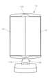
以下、本発明を図面に示す具体例に基づいて詳細に説明する。図1ないし図7は本発明に係る卓上三面鏡の好ましい実施形態を示す。図において、卓上三面鏡は鏡本体10とスタンド20とから構成され、鏡本体10は四角形状の主鏡部11と縦長四角形状の両側の副鏡部12とから構成され、副鏡部12は主鏡部11に折畳・展開し得るように枢支されている。 Hereinafter, the present invention will be explained in detail based on specific examples shown in the drawings. 1 to 7 show a preferred embodiment of a tabletop three-sided mirror according to the present invention. In the figure, the tabletop three-sided mirror is composed of a
主鏡部11及び副鏡部12では合成樹脂製ケース11A、12A内に正面から鏡板11B、12Bを嵌め込んで構成され、主鏡部11は鏡板11Bの裏面に半透光性のシートが貼り付けられて接着剤によって接着され、副鏡部12はケース12Aに枠体12Cが嵌め込まれて接着され、副鏡部12の鏡板12Bは枠体12Cによって取付け状態に保持されている。 The
主鏡部11のケース11Aには上縁及び下縁の中央の指を引っ掛けるための凹部11Dが形成され、又ケース11A背面中央には取付けベース13がケース11A背面に対して垂直な垂直軸回りに回転自在に取付けられ、ロック片13Aとストッパー11Cとが相互に係合されることによって取付けベース13は主鏡部11及び副鏡部12の縦姿勢及び横姿勢に制動されるようになっている。 The
また、取付けベース13はスタンド20上端部のコ字状ブラケット20Aに水平軸回りに回転自在に設けられている。取付けベース13には円筒部分が外側方に突出て形成され、スタンド20上端部のコ字状ブラケット20Aには円筒部分が相互に対向して形成され、取付けベース13の円筒部分とコ字状ブラケット20Aの円筒部分とは相互に回転自在にかつ密接するように嵌合されて上記水平軸が構成され、これによって主鏡部11及び副鏡部12は所望の角度に傾動されるようになっている。 Further, the
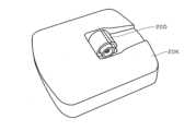
さらに、スタンド20の下端部にはコ字状ブラケット20Bが形成され、コ字状ブラケット20Bはスタンド20のベース20Kの受け部20Dに水平軸回りに回転自在に設けられている。コ字状ブラケット20Bには円筒部分20Eが相互に対向して形成され、受け部20Dには円筒部分20Fが外側方に突出して形成され、コ字状ブラケット20Bの円筒部分20Eと受け部20Dの円筒部分20Fとは相互に回転自在に嵌合されて水平軸が構成されている。 Further, a
また、受け部20Dの円筒部分20Fには半円形状のガイド溝20Gが形成され、コ字状ブラケット20Bの円筒部分20Eには円弧板部20Hが形成され、円弧板部20Hはガイド溝20G内に挿入されて回転角度が規定され、又ガイド溝20G内には突起20Jが形成され、円弧板部20Hは突起20Jと競られ、これによってスタンド20は起立姿勢及び倒伏姿勢に制動されるようになっている。 Further, a
さらに、主鏡部11のケース11A内上縁及び下縁にはLED基板11Eが設けられ、LED基板11EにはLED列が搭載され、スイッチ操作又はタッチセンサーによってケース11A内の電池がLEDに通電してLEDが点灯され、主鏡部11か照明されるようになっている。 Furthermore, an
また、スタンド20のベース20K内には重錘が内蔵され、三面鏡の点灯が防止されている。 Further, a weight is built into the base 20K of the
以上のように、スタンド20をベース20Kに対して起立・倒伏可能に設けたので、三面鏡を使用するときにはベース20Kに対してスタンド20を起立させ、鏡本体10を旋回させることによって、顔や頭髪の広い範囲を鏡に写すことができる。
他方、三面鏡を使用しないときには副鏡部11Bを主鏡部11Aに対して折り畳み、スタンド20をベース20Kに対して倒すと、全体がコンパクトになり、小さなスペースに収納することができる。As described above, since the
On the other hand, when the three-way mirror is not in use, the secondary mirror section 11B is folded up relative to the
11 主鏡部 11A 主鏡部ケース
11B 主鏡部鏡板 12 副鏡部
12A 副鏡部ケース 12B 副鏡部鏡板
20 スタンド 20K ベース
11
Claims (10)
Translated fromJapanese上記主鏡部のケース背面には取付けベースがケース背面に対して垂直な垂直軸回りに上記主鏡部及び副鏡部の縦姿勢と横姿勢との間で回転し得るように取付けられ、上記スタンド上端部のブラケット部はコ字状をなし、上記主鏡部のケース背面の取付けベースは上記スタンド上端部のコ字状ブラケット部に上記ケース背面の垂直軸に対して直交する水平軸回りに回転し得るように取付けられている一方、
上記スタンド下端部にはコ字状ブラケット部が形成され、上記スタンドが立設されるベースには受け部が形成され、該受け部には上記スタンド下端部のコ字状ブラケット部が水平軸回りに回転自在に取付けられて上記スタンドは上記スタンドが立設されるベースに対する起立姿勢と倒伏姿勢との間で傾動し得るように設けられていることを特徴とする卓上三面鏡。The mirror body is constructed with secondary mirror parts on both sides that can be opened and closed with respect to the primary mirror part, and the primary mirror part and the secondary mirror part are constructed by fitting a mirror plate into a case, while a base is placed on the floor. A stand is erected, a bracket is formed at the upper end of the stand, and a back surface of the primary mirror is attached to the bracket so as to be rotatable about a horizontal axis so that the primary mirror can be tilted. In the tabletop three-sided mirror provided,
A mounting base is attached to the back of the case of the primary mirror so that it can rotate between the vertical and horizontal positions of the primary and secondary mirrors around a vertical axis perpendicular to the back of the case. The bracketat the top end of the stand is U-shaped, and the mounting baseon the back of the case for the primary mirror is attached to the U-shaped bracket atthe top end of the stand around a horizontal axis perpendicular to the vertical axis on the back of the case. While it is installed so that it can rotate,
A U-shaped bracket portion is formed atthe lower end of the stand, a receiving portion is formed at the base on whichthe stand is erected , and the U-shaped bracketportion atthe lower end of the stand is attached to the horizontal axis. A tabletop three-way mirror, characterized in that the standis rotatably mounted around the base and is tiltable between an upright position and a collapsed position with respect to a base on which the stand is erected .
Priority Applications (1)
| Application Number | Priority Date | Filing Date | Title |
|---|---|---|---|
| JP2019145941AJP7361527B2 (en) | 2019-08-08 | 2019-08-08 | Foldable and rotating LED tabletop mirror |
Applications Claiming Priority (1)
| Application Number | Priority Date | Filing Date | Title |
|---|---|---|---|
| JP2019145941AJP7361527B2 (en) | 2019-08-08 | 2019-08-08 | Foldable and rotating LED tabletop mirror |
Publications (2)
| Publication Number | Publication Date |
|---|---|
| JP2021023688A JP2021023688A (en) | 2021-02-22 |
| JP7361527B2true JP7361527B2 (en) | 2023-10-16 |
Family
ID=74661912
Family Applications (1)
| Application Number | Title | Priority Date | Filing Date |
|---|---|---|---|
| JP2019145941AActiveJP7361527B2 (en) | 2019-08-08 | 2019-08-08 | Foldable and rotating LED tabletop mirror |
Country Status (1)
| Country | Link |
|---|---|
| JP (1) | JP7361527B2 (en) |
Citations (4)
| Publication number | Priority date | Publication date | Assignee | Title |
|---|---|---|---|---|
| JP2008272333A (en) | 2007-05-02 | 2008-11-13 | Ya Man Ltd | Triple mirror apparatus |
| JP3160837U (en) | 2010-04-28 | 2010-07-08 | 株式会社セイショー | Tabletop mirror |
| JP3179710U (en) | 2012-09-03 | 2012-11-15 | 寧波東誠家居用品製造有限公司 | Tabletop mirror |
| US10016045B1 (en) | 2017-06-16 | 2018-07-10 | E. Mishan & Sons, Inc. | Foldaway mirror |
Family Cites Families (1)
| Publication number | Priority date | Publication date | Assignee | Title |
|---|---|---|---|---|
| JP2001224098A (en)* | 2000-02-14 | 2001-08-17 | Pioneer Electronic Corp | Sound field correction method in audio system |
- 2019
- 2019-08-08JPJP2019145941Apatent/JP7361527B2/enactiveActive
Patent Citations (4)
| Publication number | Priority date | Publication date | Assignee | Title |
|---|---|---|---|---|
| JP2008272333A (en) | 2007-05-02 | 2008-11-13 | Ya Man Ltd | Triple mirror apparatus |
| JP3160837U (en) | 2010-04-28 | 2010-07-08 | 株式会社セイショー | Tabletop mirror |
| JP3179710U (en) | 2012-09-03 | 2012-11-15 | 寧波東誠家居用品製造有限公司 | Tabletop mirror |
| US10016045B1 (en) | 2017-06-16 | 2018-07-10 | E. Mishan & Sons, Inc. | Foldaway mirror |
Also Published As
| Publication number | Publication date |
|---|---|
| JP2021023688A (en) | 2021-02-22 |
Similar Documents
| Publication | Publication Date | Title |
|---|---|---|
| US7347573B1 (en) | Portable, foldable mirror | |
| US7828260B2 (en) | Deployable support unit for reading material | |
| US8567740B2 (en) | Deployable support unit for reading material | |
| US20110180682A1 (en) | Deployable support unit for reading material | |
| JPH10500232A (en) | Storage portable overhead projector | |
| US9606365B2 (en) | Mirror-based reading device | |
| JP7361527B2 (en) | Foldable and rotating LED tabletop mirror | |
| KR101008995B1 (en) | Multifunction reading stand | |
| US4146308A (en) | Foldable mirror construction | |
| KR200437555Y1 (en) | Chair reading table | |
| KR20130093199A (en) | Mirror assembly | |
| KR20210000145A (en) | Potable book stand | |
| CN219088608U (en) | Thick edge induction cosmetic mirror convenient to store | |
| KR20200109865A (en) | Bookstand having storage for base plate | |
| KR200275781Y1 (en) | A desk joined reading stand | |
| KR200318545Y1 (en) | A foldable supporting apparatus | |
| KR20170097394A (en) | Pulpit and simplicity desk having chair | |
| KR20240133266A (en) | Portable book stand | |
| US20220308334A1 (en) | Devices for magnification of objects to assist people with low vision | |
| JP2569882Y2 (en) | Folding stand mirror | |
| KR20190120870A (en) | Notebook computer support | |
| JPH10137032A (en) | Folding mirror | |
| JP3019964U (en) | Reading table | |
| KR200469481Y1 (en) | bookshelf | |
| JP3152944U (en) | Desk calendar stand |
Legal Events
| Date | Code | Title | Description |
|---|---|---|---|
| A621 | Written request for application examination | Free format text:JAPANESE INTERMEDIATE CODE: A621 Effective date:20220315 | |
| A131 | Notification of reasons for refusal | Free format text:JAPANESE INTERMEDIATE CODE: A131 Effective date:20230209 | |
| A977 | Report on retrieval | Free format text:JAPANESE INTERMEDIATE CODE: A971007 Effective date:20230217 | |
| A521 | Request for written amendment filed | Free format text:JAPANESE INTERMEDIATE CODE: A523 Effective date:20230428 | |
| TRDD | Decision of grant or rejection written | ||
| A01 | Written decision to grant a patent or to grant a registration (utility model) | Free format text:JAPANESE INTERMEDIATE CODE: A01 Effective date:20230719 | |
| R155 | Notification before disposition of declining of application | Free format text:JAPANESE INTERMEDIATE CODE: R155 | |
| A61 | First payment of annual fees (during grant procedure) | Free format text:JAPANESE INTERMEDIATE CODE: A61 Effective date:20231003 | |
| R150 | Certificate of patent or registration of utility model | Ref document number:7361527 Country of ref document:JP Free format text:JAPANESE INTERMEDIATE CODE: R150 |