JP7359880B2 - Gas flush vent for patient interface - Google Patents
Gas flush vent for patient interfaceDownload PDFInfo
- Publication number
- JP7359880B2 JP7359880B2JP2022005654AJP2022005654AJP7359880B2JP 7359880 B2JP7359880 B2JP 7359880B2JP 2022005654 AJP2022005654 AJP 2022005654AJP 2022005654 AJP2022005654 AJP 2022005654AJP 7359880 B2JP7359880 B2JP 7359880B2
- Authority
- JP
- Japan
- Prior art keywords
- patient
- air
- vent
- opening
- patient interface
- Prior art date
- Legal status (The legal status is an assumption and is not a legal conclusion. Google has not performed a legal analysis and makes no representation as to the accuracy of the status listed.)
- Active
Links
Images


Classifications
- A—HUMAN NECESSITIES
- A61—MEDICAL OR VETERINARY SCIENCE; HYGIENE
- A61M—DEVICES FOR INTRODUCING MEDIA INTO, OR ONTO, THE BODY; DEVICES FOR TRANSDUCING BODY MEDIA OR FOR TAKING MEDIA FROM THE BODY; DEVICES FOR PRODUCING OR ENDING SLEEP OR STUPOR
- A61M16/00—Devices for influencing the respiratory system of patients by gas treatment, e.g. ventilators; Tracheal tubes
- A61M16/06—Respiratory or anaesthetic masks
- A61M16/0605—Means for improving the adaptation of the mask to the patient
- A61M16/0616—Means for improving the adaptation of the mask to the patient with face sealing means comprising a flap or membrane projecting inwards, such that sealing increases with increasing inhalation gas pressure
- A61M16/0622—Means for improving the adaptation of the mask to the patient with face sealing means comprising a flap or membrane projecting inwards, such that sealing increases with increasing inhalation gas pressure having an underlying cushion
- A—HUMAN NECESSITIES
- A61—MEDICAL OR VETERINARY SCIENCE; HYGIENE
- A61M—DEVICES FOR INTRODUCING MEDIA INTO, OR ONTO, THE BODY; DEVICES FOR TRANSDUCING BODY MEDIA OR FOR TAKING MEDIA FROM THE BODY; DEVICES FOR PRODUCING OR ENDING SLEEP OR STUPOR
- A61M16/00—Devices for influencing the respiratory system of patients by gas treatment, e.g. ventilators; Tracheal tubes
- A61M16/06—Respiratory or anaesthetic masks
- A—HUMAN NECESSITIES
- A61—MEDICAL OR VETERINARY SCIENCE; HYGIENE
- A61B—DIAGNOSIS; SURGERY; IDENTIFICATION
- A61B5/00—Measuring for diagnostic purposes; Identification of persons
- A61B5/48—Other medical applications
- A61B5/4806—Sleep evaluation
- A61B5/4818—Sleep apnoea
- A—HUMAN NECESSITIES
- A61—MEDICAL OR VETERINARY SCIENCE; HYGIENE
- A61M—DEVICES FOR INTRODUCING MEDIA INTO, OR ONTO, THE BODY; DEVICES FOR TRANSDUCING BODY MEDIA OR FOR TAKING MEDIA FROM THE BODY; DEVICES FOR PRODUCING OR ENDING SLEEP OR STUPOR
- A61M16/00—Devices for influencing the respiratory system of patients by gas treatment, e.g. ventilators; Tracheal tubes
- A61M16/0003—Accessories therefor, e.g. sensors, vibrators, negative pressure
- A—HUMAN NECESSITIES
- A61—MEDICAL OR VETERINARY SCIENCE; HYGIENE
- A61M—DEVICES FOR INTRODUCING MEDIA INTO, OR ONTO, THE BODY; DEVICES FOR TRANSDUCING BODY MEDIA OR FOR TAKING MEDIA FROM THE BODY; DEVICES FOR PRODUCING OR ENDING SLEEP OR STUPOR
- A61M16/00—Devices for influencing the respiratory system of patients by gas treatment, e.g. ventilators; Tracheal tubes
- A61M16/0057—Pumps therefor
- A61M16/0066—Blowers or centrifugal pumps
- A—HUMAN NECESSITIES
- A61—MEDICAL OR VETERINARY SCIENCE; HYGIENE
- A61M—DEVICES FOR INTRODUCING MEDIA INTO, OR ONTO, THE BODY; DEVICES FOR TRANSDUCING BODY MEDIA OR FOR TAKING MEDIA FROM THE BODY; DEVICES FOR PRODUCING OR ENDING SLEEP OR STUPOR
- A61M16/00—Devices for influencing the respiratory system of patients by gas treatment, e.g. ventilators; Tracheal tubes
- A61M16/0087—Environmental safety or protection means, e.g. preventing explosion
- A61M16/009—Removing used or expired gases or anaesthetic vapours
- A—HUMAN NECESSITIES
- A61—MEDICAL OR VETERINARY SCIENCE; HYGIENE
- A61M—DEVICES FOR INTRODUCING MEDIA INTO, OR ONTO, THE BODY; DEVICES FOR TRANSDUCING BODY MEDIA OR FOR TAKING MEDIA FROM THE BODY; DEVICES FOR PRODUCING OR ENDING SLEEP OR STUPOR
- A61M16/00—Devices for influencing the respiratory system of patients by gas treatment, e.g. ventilators; Tracheal tubes
- A61M16/06—Respiratory or anaesthetic masks
- A61M16/0605—Means for improving the adaptation of the mask to the patient
- A61M16/0611—Means for improving the adaptation of the mask to the patient with a gusset portion
- A—HUMAN NECESSITIES
- A61—MEDICAL OR VETERINARY SCIENCE; HYGIENE
- A61M—DEVICES FOR INTRODUCING MEDIA INTO, OR ONTO, THE BODY; DEVICES FOR TRANSDUCING BODY MEDIA OR FOR TAKING MEDIA FROM THE BODY; DEVICES FOR PRODUCING OR ENDING SLEEP OR STUPOR
- A61M16/00—Devices for influencing the respiratory system of patients by gas treatment, e.g. ventilators; Tracheal tubes
- A61M16/06—Respiratory or anaesthetic masks
- A61M16/0605—Means for improving the adaptation of the mask to the patient
- A61M16/0627—Means for improving the adaptation of the mask to the patient with sealing means on a part of the body other than the face, e.g. helmets, hoods or domes
- A—HUMAN NECESSITIES
- A61—MEDICAL OR VETERINARY SCIENCE; HYGIENE
- A61M—DEVICES FOR INTRODUCING MEDIA INTO, OR ONTO, THE BODY; DEVICES FOR TRANSDUCING BODY MEDIA OR FOR TAKING MEDIA FROM THE BODY; DEVICES FOR PRODUCING OR ENDING SLEEP OR STUPOR
- A61M16/00—Devices for influencing the respiratory system of patients by gas treatment, e.g. ventilators; Tracheal tubes
- A61M16/06—Respiratory or anaesthetic masks
- A61M16/0605—Means for improving the adaptation of the mask to the patient
- A61M16/0633—Means for improving the adaptation of the mask to the patient with forehead support
- A—HUMAN NECESSITIES
- A61—MEDICAL OR VETERINARY SCIENCE; HYGIENE
- A61M—DEVICES FOR INTRODUCING MEDIA INTO, OR ONTO, THE BODY; DEVICES FOR TRANSDUCING BODY MEDIA OR FOR TAKING MEDIA FROM THE BODY; DEVICES FOR PRODUCING OR ENDING SLEEP OR STUPOR
- A61M16/00—Devices for influencing the respiratory system of patients by gas treatment, e.g. ventilators; Tracheal tubes
- A61M16/06—Respiratory or anaesthetic masks
- A61M16/0683—Holding devices therefor
- A—HUMAN NECESSITIES
- A61—MEDICAL OR VETERINARY SCIENCE; HYGIENE
- A61M—DEVICES FOR INTRODUCING MEDIA INTO, OR ONTO, THE BODY; DEVICES FOR TRANSDUCING BODY MEDIA OR FOR TAKING MEDIA FROM THE BODY; DEVICES FOR PRODUCING OR ENDING SLEEP OR STUPOR
- A61M16/00—Devices for influencing the respiratory system of patients by gas treatment, e.g. ventilators; Tracheal tubes
- A61M16/08—Bellows; Connecting tubes ; Water traps; Patient circuits
- A61M16/0866—Passive resistors therefor
- A—HUMAN NECESSITIES
- A61—MEDICAL OR VETERINARY SCIENCE; HYGIENE
- A61M—DEVICES FOR INTRODUCING MEDIA INTO, OR ONTO, THE BODY; DEVICES FOR TRANSDUCING BODY MEDIA OR FOR TAKING MEDIA FROM THE BODY; DEVICES FOR PRODUCING OR ENDING SLEEP OR STUPOR
- A61M16/00—Devices for influencing the respiratory system of patients by gas treatment, e.g. ventilators; Tracheal tubes
- A61M16/08—Bellows; Connecting tubes ; Water traps; Patient circuits
- A61M16/0875—Connecting tubes
- A—HUMAN NECESSITIES
- A61—MEDICAL OR VETERINARY SCIENCE; HYGIENE
- A61M—DEVICES FOR INTRODUCING MEDIA INTO, OR ONTO, THE BODY; DEVICES FOR TRANSDUCING BODY MEDIA OR FOR TAKING MEDIA FROM THE BODY; DEVICES FOR PRODUCING OR ENDING SLEEP OR STUPOR
- A61M16/00—Devices for influencing the respiratory system of patients by gas treatment, e.g. ventilators; Tracheal tubes
- A61M16/10—Preparation of respiratory gases or vapours
- A61M16/1075—Preparation of respiratory gases or vapours by influencing the temperature
- A—HUMAN NECESSITIES
- A61—MEDICAL OR VETERINARY SCIENCE; HYGIENE
- A61M—DEVICES FOR INTRODUCING MEDIA INTO, OR ONTO, THE BODY; DEVICES FOR TRANSDUCING BODY MEDIA OR FOR TAKING MEDIA FROM THE BODY; DEVICES FOR PRODUCING OR ENDING SLEEP OR STUPOR
- A61M16/00—Devices for influencing the respiratory system of patients by gas treatment, e.g. ventilators; Tracheal tubes
- A61M16/10—Preparation of respiratory gases or vapours
- A61M16/14—Preparation of respiratory gases or vapours by mixing different fluids, one of them being in a liquid phase
- A61M16/16—Devices to humidify the respiration air
- A—HUMAN NECESSITIES
- A61—MEDICAL OR VETERINARY SCIENCE; HYGIENE
- A61M—DEVICES FOR INTRODUCING MEDIA INTO, OR ONTO, THE BODY; DEVICES FOR TRANSDUCING BODY MEDIA OR FOR TAKING MEDIA FROM THE BODY; DEVICES FOR PRODUCING OR ENDING SLEEP OR STUPOR
- A61M16/00—Devices for influencing the respiratory system of patients by gas treatment, e.g. ventilators; Tracheal tubes
- A61M16/20—Valves specially adapted to medical respiratory devices
- A—HUMAN NECESSITIES
- A61—MEDICAL OR VETERINARY SCIENCE; HYGIENE
- A61M—DEVICES FOR INTRODUCING MEDIA INTO, OR ONTO, THE BODY; DEVICES FOR TRANSDUCING BODY MEDIA OR FOR TAKING MEDIA FROM THE BODY; DEVICES FOR PRODUCING OR ENDING SLEEP OR STUPOR
- A61M16/00—Devices for influencing the respiratory system of patients by gas treatment, e.g. ventilators; Tracheal tubes
- A61M16/10—Preparation of respiratory gases or vapours
- A61M16/12—Preparation of respiratory gases or vapours by mixing different gases
- A61M16/122—Preparation of respiratory gases or vapours by mixing different gases with dilution
- A61M16/125—Diluting primary gas with ambient air
- A—HUMAN NECESSITIES
- A61—MEDICAL OR VETERINARY SCIENCE; HYGIENE
- A61M—DEVICES FOR INTRODUCING MEDIA INTO, OR ONTO, THE BODY; DEVICES FOR TRANSDUCING BODY MEDIA OR FOR TAKING MEDIA FROM THE BODY; DEVICES FOR PRODUCING OR ENDING SLEEP OR STUPOR
- A61M2205/00—General characteristics of the apparatus
- A61M2205/42—Reducing noise
- A—HUMAN NECESSITIES
- A61—MEDICAL OR VETERINARY SCIENCE; HYGIENE
- A61M—DEVICES FOR INTRODUCING MEDIA INTO, OR ONTO, THE BODY; DEVICES FOR TRANSDUCING BODY MEDIA OR FOR TAKING MEDIA FROM THE BODY; DEVICES FOR PRODUCING OR ENDING SLEEP OR STUPOR
- A61M2230/00—Measuring parameters of the user
- A61M2230/40—Respiratory characteristics
- A61M2230/42—Rate
Landscapes
- Health & Medical Sciences (AREA)
- Life Sciences & Earth Sciences (AREA)
- Engineering & Computer Science (AREA)
- Veterinary Medicine (AREA)
- Biomedical Technology (AREA)
- Heart & Thoracic Surgery (AREA)
- Animal Behavior & Ethology (AREA)
- General Health & Medical Sciences (AREA)
- Public Health (AREA)
- Anesthesiology (AREA)
- Hematology (AREA)
- Pulmonology (AREA)
- Emergency Medicine (AREA)
- Biophysics (AREA)
- Physics & Mathematics (AREA)
- Pathology (AREA)
- Medical Informatics (AREA)
- Molecular Biology (AREA)
- Surgery (AREA)
- Ecology (AREA)
- Biodiversity & Conservation Biology (AREA)
- Environmental & Geological Engineering (AREA)
- Environmental Sciences (AREA)
- Orthopedics, Nursing, And Contraception (AREA)
- Respiratory Apparatuses And Protective Means (AREA)
- Medicines Containing Antibodies Or Antigens For Use As Internal Diagnostic Agents (AREA)
- Radiation-Therapy Devices (AREA)
Description
Translated fromJapanese本出願は、2016年11月11日に出願された米国仮出願第62/420,678号の恩恵を主張する。本明細書中、同文献全体を参考のため援用する。 This application claims the benefit of U.S. Provisional Application No. 62/420,678, filed on November 11, 2016. The entire document is incorporated herein by reference.
1 技術の背景
1.1 技術の分野
本技術は、呼吸関連疾患の検出、診断、治療、予防および改善のうち1つ以上に関する。本技術はまた、医療デバイスまたは装置と、その使用とに関する。1 Background of the Technology 1.1 Field of the Technology The present technology relates to one or more of the detection, diagnosis, treatment, prevention, and amelioration of respiratory-related diseases. The technology also relates to medical devices or apparatus and uses thereof.
1.2 関連技術の説明
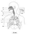
1.2.1 ヒトの呼吸器系およびその疾患
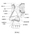
身体の呼吸器系は、ガス交換を促進させる。鼻および口腔は、患者の気道への入口を形成する。1.2 Description of Related Art 1.2.1 Human Respiratory System and Its Diseases The body's respiratory system facilitates gas exchange. The nose and oral cavity form the entrance to the patient's airways.
これらの気道は、一連の分岐する管を含み、これらの管は、肺の奥深くに進むほど狭く、短くかつ多数になる。肺の主要な機能はガス交換であり、空気から酸素を静脈血中へ取り入れさせ、二酸化炭素を退出させる。気管は、右および左の主気管支に分かれ、これらの主気管支はさらに分かれて、最終的に終末細気管支となる。気管支は、伝導のための気道を構成するものであり、ガス交換には関与しない。気道がさらに分割されると呼吸細気管支となり、最終的には肺胞となる。肺の肺胞領域においてガス交換が行われ、この領域を呼吸ゾーンと呼ぶ。以下を参照されたい:「Respiratory Physiology」, by John B. West, Lippincott Williams & Wilkins, 9th edition published 2012。 These airways contain a series of branching tubes that become narrower, shorter, and more numerous the deeper they go into the lungs. The primary function of the lungs is gas exchange, bringing oxygen from the air into the venous blood and expelling carbon dioxide. The trachea divides into right and left main bronchi, which further divide into terminal bronchioles. The bronchi constitute airways for conduction and are not involved in gas exchange. The airways are further divided into respiratory bronchioles and finally into alveoli. Gas exchange takes place in the alveolar region of the lungs, this region is called the respiratory zone. See: "Respiratory Physiology", by John B. West, Lippincott Williams & Wilkins, 9th edition published 2012.
一定範囲の呼吸器疾患が存在している。特定の疾患は、特定の発症(例えば、無呼吸、呼吸低下および過呼吸)によって特徴付けられ得る。 A range of respiratory diseases exist. Certain diseases may be characterized by specific episodes such as apnea, hypopnea and hyperpnea.
呼吸器疾患の例には、閉塞性睡眠時無呼吸(OSA)、チェーン・ストークス呼吸(CSR)、呼吸不全、肥満過換気症候群(OHS)、慢性閉塞性肺疾患(COPD)、神経筋疾患(NMD)および胸壁疾患が含まれる。 Examples of respiratory diseases include obstructive sleep apnea (OSA), Cheyne-Stokes respiration (CSR), respiratory failure, obesity hyperventilation syndrome (OHS), chronic obstructive pulmonary disease (COPD), and neuromuscular diseases ( NMD) and chest wall disease.
閉塞性睡眠時無呼吸(OSA)は、睡眠呼吸障害(SDB)の1つの形態であり、睡眠時の上通気道の閉鎖または閉塞などの発症によって特徴付けられる。睡眠時の異常に小さな上側気道および舌領域における筋緊張の正常欠損、軟口蓋および後中咽頭壁の組み合わせに起因する。このような状態に起因して、罹患患者の呼吸停止が典型的には30~120秒にわたり、ときには一晩に200~300回も呼吸が停止する。その結果、日中の眠気が過度になり、心血管疾患および脳損傷の原因になり得る。この症候は一般的な疾患であり、特に中年の過体重の男性に多いが、患者に自覚症状は無い。米国特許第4,944,310号(Sullivan)を参照されたい。 Obstructive sleep apnea (OSA) is a form of sleep disordered breathing (SDB) characterized by episodes such as closure or obstruction of the upper airway during sleep. Due to a combination of abnormally small upper airway and normal deficits in muscle tone in the tongue region, soft palate and posterior oropharyngeal wall during sleep. These conditions typically cause affected patients to stop breathing for 30 to 120 seconds, sometimes as many as 200 to 300 times a night. The result is excessive daytime sleepiness, which can lead to cardiovascular disease and brain damage. This condition is common, especially among middle-aged, overweight men, but patients have no symptoms. See US Pat. No. 4,944,310 (Sullivan).
チェーン・ストークス呼吸(CSR)は、別の形態の睡眠呼吸障害である。CSRは、患者の呼吸調節器の疾患であり、CSRサイクルとして知られる換気の漸増および漸減が交互に周期的に続く。CSRは、動脈血の脱酸素および再曝気の繰り返しによって特徴付けられる。反復低酸素症のため、CSRは有害であり得る。患者によっては、CCRは、重症不眠、交感神経活動の増加、および後負荷の増加の原因となる、反復性睡眠覚醒を随伴する。米国特許第6,532,959号(Berthon-Jones)を参照されたい。 Cheyne-Stokes respiration (CSR) is another form of sleep breathing disorder. CSR is a disease of a patient's respiratory regulator that involves periodic alternating increases and decreases in ventilation known as CSR cycles. CSR is characterized by repeated deoxygenation and reaeration of arterial blood. CSR can be harmful due to repeated hypoxia. In some patients, CCR is accompanied by recurrent sleep-wakes that cause severe insomnia, increased sympathetic activity, and increased afterload. See US Pat. No. 6,532,959 (Berthon-Jones).
呼吸不全とは、呼吸器障害の総称であり、患者の需要を満たすための充分な酸素吸気または充分なCO2呼気を肺が行うことができていないことを指す。呼吸不全は、以下の疾患のうちいくつかまたは全てを包含し得る。 Respiratory failure is a general term for respiratory disorders and refers to the inability of the lungs to inhale enough oxygen or exhale enough CO2 to meet the patient's needs. Respiratory failure may include some or all of the following diseases.
呼吸不全(一種の呼吸不全)の患者は、運動時に異常な息切れを経験することがある。 Patients with respiratory failure (a type of respiratory failure) may experience unusual shortness of breath when exercising.
肥満低呼吸症候群(OHS)は、低換気の他の既知の原因がない場合、重症の肥満と覚醒時慢性高炭酸ガス血症の組み合わせとして定義される。症状には、呼吸困難、起床時の頭痛と過剰な日中の眠気が含まれる。 Obesity hypoventilation syndrome (OHS) is defined as the combination of severe obesity and chronic waking hypercapnia in the absence of other known causes of hypoventilation. Symptoms include difficulty breathing, headache upon waking and excessive daytime sleepiness.
慢性閉塞性肺疾患(COPD)は、特定の共通する特性を有する下気道疾患のグループのうちのいずれも包含する。これには空気の動きに対する抵抗の増加、呼吸の呼気相の延長および肺における正常な弾性の減少が含まれる。COPDの例として、気腫および慢性気管支炎がある。COPDの原因としては、慢性喫煙(第一危険因子)、職業被ばく、空気汚染および遺伝因子がある。症状を挙げると、労作時の呼吸困難、慢性咳および痰生成がある。 Chronic obstructive pulmonary disease (COPD) encompasses any of a group of lower respiratory tract diseases that have certain common characteristics. This includes increased resistance to air movement, prolongation of the expiratory phase of breathing, and decreased normal elasticity in the lungs. Examples of COPD include emphysema and chronic bronchitis. Causes of COPD include chronic smoking (the primary risk factor), occupational exposure, air pollution, and genetic factors. Symptoms include difficulty breathing on exertion, chronic cough, and sputum production.
神経筋疾患(NMD)は、内在筋病理を直接介してまたは神経病理を間接的に介して筋肉機能を損なう多数の疾病および病気を包含する広範な用語である。NMD患者の中には、進行性の筋肉障害によって特徴付けられる者もあり、結果的に歩行不可能、車椅子への束縛、嚥下困難、呼吸筋力低下に繋がり、最終的には呼吸不全による死亡に繋がる。神経筋肉障害は、以下の急速進行性と緩徐進行性とに区分され得る:(i)急速進行性障害:数ヶ月かけて悪化する筋肉障害によって特徴付けられ、数年内に死亡に繋がる(例えば、ティーンエージャーにおける筋萎縮性側索硬化症(ALS)およびデュシェンヌ筋ジストロフィー(DMD));(ii)可変性または緩徐進行性障害:数年かけて悪化する筋肉障害によって特徴付けられ、平均余命が若干低減するだけである(例えば、肢帯、顔面肩甲上腕型および筋強直性筋ジストロフィー)。NMDにおける呼吸不全症状を以下に挙げる:全身衰弱の増加、嚥下障害、労作および安静時の呼吸困難、疲労、眠気、起床時の頭痛、および集中および気分の変化の困難。 Neuromuscular disease (NMD) is a broad term that encompasses a number of diseases and conditions that impair muscle function, either directly through intrinsic muscle pathology or indirectly through neuropathology. Some NMD patients are characterized by progressive muscle damage, resulting in inability to walk, wheelchair confinement, difficulty swallowing, respiratory muscle weakness, and ultimately death from respiratory failure. Connect. Neuromuscular disorders can be divided into rapidly progressive and slowly progressive disorders: (i) Rapidly progressive disorders: characterized by muscle impairment that worsens over months, leading to death within a few years (e.g. amyotrophic lateral sclerosis (ALS) and Duchenne muscular dystrophy (DMD) in teenagers; (ii) variable or slowly progressive disorder: characterized by muscle impairment that worsens over several years, resulting in a slight reduction in life expectancy; only (e.g. limb girdle, facioscapulohumeral and myotonic muscular dystrophies). Respiratory failure symptoms in NMD include: increased general weakness, difficulty swallowing, difficulty breathing on exertion and at rest, fatigue, drowsiness, headache upon awakening, and difficulty concentrating and mood changes.
胸壁障害は、胸郭変形の1つのグループであり、呼吸筋肉と胸郭との間の連結の無効性の原因となる。これらの障害は、拘束性障害によって主に特徴付けられ、長期の炭酸過剰性呼吸不全の可能性を共有する。脊柱側弯症および/または脊柱後側弯症は、重篤な呼吸不全を発症することがある。呼吸不全の症状を以下に挙げる:労作時の呼吸困難、末梢浮腫、起座呼吸、反復性胸部感染症、起床時の頭痛、疲労、睡眠の質の低下、および食欲不振。 Chest wall disorders are a group of thoracic deformities that cause ineffective connections between the respiratory muscles and the thorax. These disorders are primarily characterized by restrictive deficits and share the potential for long-term hypercapnic respiratory failure. Scoliosis and/or kyphoscoliosis can develop severe respiratory failure. Symptoms of respiratory failure include: dyspnea on exertion, peripheral edema, orthopnea, recurrent chest infections, headache upon awakening, fatigue, poor sleep quality, and loss of appetite.
このような状態を治療または改善するために、一定範囲の治療が用いられている。さらに、その他の点では健常人も、呼吸器疾患の予防治療を有利に利用することができる。しかし、これらにおいては、複数の欠陥がある。 A range of treatments are used to treat or ameliorate such conditions. Additionally, otherwise healthy individuals can also benefit from preventive treatment of respiratory diseases. However, these have several deficiencies.
1.2.2 治療法
多様な療法(例えば、持続的気道陽圧(CPAP)治療法、非侵襲的換気(NIV)および侵襲的換気(IV))が上記の呼吸器疾患の1つ以上の治療のために用いられている。1.2.2 Treatment A variety of therapies (e.g. continuous positive airway pressure (CPAP) therapy, non-invasive ventilation (NIV) and invasive ventilation (IV)) can treat one or more of the respiratory diseases listed above. Used for treatment.
持続的気道陽圧(CPAP)療法が、閉塞性睡眠時無呼吸(OSA)の治療において用いられている。その作用メカニズムとしては、例えば軟口蓋および舌を押して後中咽頭壁へ前進または後退させることにより、経鼻的持続陽圧呼吸療法が空気スプリントとして機能し、これにより上側気道の閉鎖を回避する。CPAP治療によるOSAの治療は自発的なものであり得るため、このような患者が治療の提供に用いられるデバイスについて以下のうち1つ以上に気づいた場合、患者が治療を遵守しないことを選択する可能性がある:不快、使用困難、高価、美観的な魅力の無さ。 Continuous positive airway pressure (CPAP) therapy has been used in the treatment of obstructive sleep apnea (OSA). Its mechanism of action is that nasal continuous positive airway pressure acts as an air splint, e.g. by pushing the soft palate and tongue forward or backward toward the posterior oropharyngeal wall, thereby avoiding closure of the upper airway. Because treatment of OSA with CPAP therapy can be voluntary, such patients choose not to comply with treatment if they notice one or more of the following about the device used to deliver treatment: Can be: uncomfortable, difficult to use, expensive, aesthetically unappealing.
非侵襲的換気(NIV)は、換気補助を上気道を通じて患者へ提供して、呼吸機能の一部または全体を行うことにより患者の呼吸の補助および/または身体中の適切な酸素レベルの維持を提供する。換気補助が、非侵襲的患者インターフェースを介して提供される。NIVは、OHS、COPD、NMD、および胸壁障害などの形態のCSRおよび呼吸不全の治療に用いられている。いくつかの形態において、これらの治療の快適性および有効性が向上し得る。 Non-invasive ventilation (NIV) is the provision of ventilatory assistance to a patient through the upper airway to assist the patient in breathing and/or maintain adequate oxygen levels in the body by performing some or all of the respiratory functions. provide. Ventilatory assistance is provided via a non-invasive patient interface. NIV has been used to treat forms of CSR and respiratory failure such as OHS, COPD, NMD, and chest wall disorders. In some forms, the comfort and effectiveness of these treatments may be improved.
侵襲的換気(IV)は、自身で有効に呼吸することができなくなった患者に対して換気補助を提供し、気管切開管を用いて提供され得る。いくつかの形態において、これらの治療の快適性および有効性が向上し得る。 Invasive ventilation (IV) provides ventilatory assistance to patients who are no longer able to breathe effectively on their own and may be provided using a tracheostomy tube. In some forms, the comfort and effectiveness of these treatments may be improved.
1.2.3 治療システム
これらの治療は、治療システムまたはデバイスによって提供され得る。このようなシステムおよびデバイスは、疾患を治療することなく診断するためにも、用いられ得る。1.2.3 Treatment Systems These treatments may be provided by treatment systems or devices. Such systems and devices can also be used to diagnose disease without treating it.
治療システムは、呼吸圧力治療デバイス(RPTデバイス)、空気回路、加湿器、患者インターフェース、およびデータ管理を含み得る。 The therapy system may include a respiratory pressure therapy device (RPT device), an air circuit, a humidifier, a patient interface, and data management.
別の形態の治療システムとして、下顎再位置決めデバイスがある。 Another form of treatment system is a mandibular repositioning device.
1.2.3.1 患者インターフェース
患者インターフェースは、例えば気道入口への空気流れを提供することにより呼吸装具へのインターフェースを装着者へ提供するために、用いられ得る。空気流れは、鼻および/または口腔へのマスク、口腔への管、または患者気管への気管切開管を介して提供され得る。適用される療法に応じて、患者インターフェースは、例えば患者の顔の領域との密閉部を形成し得、これにより、療法実行のための雰囲気圧力と共に充分な分散の圧力において(例えば、例えば雰囲気圧力に対して約10cmH2Oの陽圧において)ガス送達を促進する。酸素送達などの他の治療形態において、患者インターフェースは、約10cmH2Oの陽圧において気道へのガス供給の送達を促進するのに充分な密閉を含まない場合がある。1.2.3.1 Patient Interface A patient interface may be used to provide an interface to a breathing apparatus to a wearer, for example by providing airflow to the airway entrance. Airflow may be provided via a mask to the nose and/or oral cavity, a tube to the oral cavity, or a tracheostomy tube to the patient's trachea. Depending on the therapy to be applied, the patient interface may, for example, form a seal with the area of the patient's face, so that at a pressure of sufficient dispersion together with ambient pressure for the performance of the therapy (e.g. (at a positive pressure of about 10 cm H2 O) to facilitate gas delivery. In other forms of therapy, such as oxygen delivery, the patient interface may not include a sufficient seal to facilitate delivery of gas supply to the airways at a positive pressure of about 10 cmH2O .
特定の他のマスクシステムは、本分野において機能的に不適切であり得る。例えば、純然たる装飾目的のマスクの場合、適切な圧力を維持することができない場合がある。水中水泳またはダイビングに用いられるマスクシステムは、外部からのより高い圧力からの水侵入から保護することと、周囲よりも高い圧力において内部の空気を維持しないこととを行うように、構成され得る。 Certain other mask systems may be functionally inadequate in the art. For example, masks that are purely decorative may not be able to maintain adequate pressure. Mask systems used for underwater swimming or diving can be configured to protect against water ingress from higher pressures from the outside and to not maintain internal air at a higher pressure than the surroundings.
特定のマスクは、本技術において臨床的に好ましく無い場合があり得る(例えば、マスクが鼻を介して気流を遮断し、口を介した気流のみを通過させる場合)。 Certain masks may not be clinically preferred in this technology (eg, if the mask blocks airflow through the nose and only allows airflow through the mouth).
特定のマスクにおいて、患者がマスク構造の一部を口に挿入し、唇を介して密閉状態を生成および維持しなければならない場合、本技術において不快であるかまたは非実際的である場合がある。 With certain masks, this technique may be uncomfortable or impractical if the patient must insert a portion of the mask structure into the mouth and create and maintain a seal through the lips. .
特定のマスクは、睡眠時(例えば、横向きにベッドに寝て枕の上に頭を置いた状態で睡眠する場合)における使用においては非実際的である場合がある。 Certain masks may be impractical for use during sleep (eg, sleeping on your side in bed with your head on a pillow).
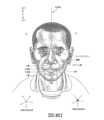
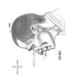
患者インターフェースの設計においては、複数の課題がある。顔は、複雑な三次元形状を有する。鼻および頭のサイズおよび形状は、個人によって大きく異なる。頭部には骨、軟骨および軟組織が含まれるため、顔の異なる領域は、機械的力に対して異なる反応を示す。すなわち、顎部または下顎は、頭蓋骨の他の骨に相対して動き得る。頭部全体は、呼吸治療期間を通じて動き得る。 There are multiple challenges in patient interface design. A face has a complex three-dimensional shape. The size and shape of the nose and head vary widely between individuals. Because the head contains bone, cartilage, and soft tissue, different areas of the face respond differently to mechanical forces. That is, the jaw or mandible can move relative to other bones of the skull. The entire head may move throughout the respiratory treatment period.
これらの課題に起因して、いくつかのマスクの場合、特に装着時間が長い場合または患者がシステムに不慣れである場合、押しつけがましい、美観的に望ましくない、コストが高い、フィット感が悪い、使用が困難、および不快感があるなどの理由のうち1つ以上がある。誤ったサイズのマスクが用いられた場合、コンプライアンスの低下、快適性の低下および患者予後の低下に繋がり得る。飛行士専用のマスク、個人用保護装具(例えば、フィルターマスク)、SCUBAマスクの一部として設計されたマスク、または麻酔投与用マスクは、その元々の用途には耐えられるものの、このようなマスクの場合、長時間(例えば、数時間)にわたって装着するには望ましくないほど不快な場合がある。このような不快感に起因して、治療に対する患者の承諾が低下する可能性がある。これは、マスクを睡眠時に装着する必要がある場合、特に当てはまる。 Due to these challenges, some masks may be intrusive, aesthetically undesirable, costly, have a poor fit, or be difficult to use, especially if the wear time is long or the patient is unfamiliar with the system. For one or more of the following reasons: difficulty and discomfort. If the wrong size mask is used, it can lead to decreased compliance, decreased comfort, and decreased patient outcome. Although aviator-specific masks, personal protective equipment (e.g., filter masks), masks designed as part of a SCUBA mask, or anesthesia administration masks may withstand their original purpose, such masks may In some cases, it may be undesirably uncomfortable to wear for extended periods of time (eg, several hours). Such discomfort may reduce patient compliance with treatment. This is especially true if the mask needs to be worn while sleeping.
CPAP治療は、患者が治療を承諾している場合、特定の呼吸疾患の治療においては極めて効果的である。マスクが不快である場合または使用が難しい場合、患者は、治療を承諾しない場合がある。患者はマスクを定期的に洗浄するよう推奨されることが多いため、マスクの清浄が難しい(例えば、組立または分解が困難である場合)、患者は、マスクを清浄することができず、患者の承諾に影響が出る場合がある。 CPAP therapy is highly effective in treating certain respiratory disorders if the patient consents to treatment. If the mask is uncomfortable or difficult to use, the patient may not consent to treatment. Patients are often encouraged to clean their masks regularly, so if the mask is difficult to clean (e.g., difficult to assemble or disassemble), the patient may not be able to clean the mask and the patient's Consent may be affected.
他の用途(例えば、飛行士)用のマスクの場合、睡眠呼吸障害の治療の使用には不適である場合があるため、睡眠呼吸障害の治療の使用のために設計されたマスクは、他の用途に適している場合がある。 Masks designed for use in the treatment of sleep-disordered breathing may not be suitable for use in the treatment of sleep-disordered breathing, as masks intended for other uses (e.g., aviators) may be unsuitable for use in the treatment of sleep-disordered breathing. It may be suitable for your application.
これらの理由のめ、睡眠時のCPAP送達のための患者インターフェースは、明瞭な分野を形成する。 For these reasons, patient interfaces for CPAP delivery during sleep form a distinct field.
1.2.3.1.1 シール形成構造
患者インターフェースはシール形成構造を含み得る。患者インターフェースは、患者の顔と直接接触するため、シール形成構造の形状および構成は、患者インターフェースの有効性および快適性に直接影響を持ち得る。1.2.3.1.1 Seal-Forming Structure The patient interface may include a seal-forming structure. Because the patient interface is in direct contact with the patient's face, the shape and configuration of the seal-forming structure can have a direct impact on the effectiveness and comfort of the patient interface.
患者インターフェースは、使用時にシール形成構造を顔と係合させる場所の設計意図に従って、部分的に特徴付けられ得る。患者インターフェースの一形態において、シール形成構造は、左鼻孔の周囲にシールを形成するための第1のサブ部分と、右鼻孔の周囲にシールを形成するための第2のサブ部分とを含み得る。患者インターフェースの一形態において、シール形成構造は、使用時において双方の鼻孔を包囲する単一の要素を含み得る。このような単一の要素は、例えば顔の上唇領域および鼻ブリッジ領域上に載置されるように、設計され得る。患者インターフェースの一形態において、シール形成構造は、使用時に例えば顔の下唇領域上にシールを形成することにより口腔領域を包囲する要素を含み得る。患者インターフェースの一形態において、シール形成構造は、使用時に双方の鼻孔および口領域を包囲する単一の要素を含み得る。これらの異なる種類の患者インターフェースは、その製造業者によって鼻マスク、フルフェイスマスク、鼻枕、鼻パフおよび口鼻マスクなどの多様な名称によって公知であり得る。 The patient interface may be characterized in part according to the design intent of where the seal-forming structure engages the face during use. In one form of the patient interface, the seal-forming structure may include a first sub-portion for forming a seal around the left nostril and a second sub-portion for forming a seal around the right nostril. . In one form of patient interface, the seal-forming structure may include a single element that surrounds both nostrils in use. Such a single element may be designed to be placed on the upper lip area and nasal bridge area of the face, for example. In one form of the patient interface, the seal-forming structure may include elements that encircle the oral cavity area, such as by forming a seal over the lower lip area of the face, in use. In one form of patient interface, the seal-forming structure may include a single element that surrounds both nostrils and mouth areas in use. These different types of patient interfaces may be known by various names such as nasal masks, full face masks, nasal pillows, nasal puffs, and oronasal masks depending on their manufacturers.
患者の顔の一領域において有効であり得るシール形成構造は、例えば患者の顔の異なる形状、構造、変化性および感受性領域に起因して、別の領域において不適切であり得る。例えば、患者の前額上に載置される水泳用ゴーグルの密閉部は、患者の鼻上における使用には不適切である場合がある。 A seal-forming structure that may be effective in one area of a patient's face may be inappropriate in another area due to, for example, the different shape, structure, variability, and sensitive areas of the patient's face. For example, a seal on swim goggles that rests on a patient's forehead may be inappropriate for use on the patient's nose.
特定のシール形成構造は、広範囲の異なる顔形状およびサイズに対して1つの設計が適合し、快適でありかつ有効になるように、大量製造用に設計され得る。密閉部を形成するためには、患者の顔の形状と、大量製造された患者インターフェースのシール形成構造との間の不整合がある範囲まで、一方または双方を適合させる必要がある。 A particular seal-forming structure can be designed for mass manufacturing so that one design is suitable, comfortable, and effective for a wide range of different facial shapes and sizes. Forming a seal requires matching one or both to the extent that there is a mismatch between the shape of the patient's face and the seal-forming structure of the mass-manufactured patient interface.
1つの種類のシール形成構造は、患者インターフェースの周囲を包囲して延び、シール形成構造が患者の顔に対向して係合している状態で力が患者インターフェースへ付加された際、患者の顔を密閉することを意図する。このシール形成構造は、空気または流体充填クッションを含み得るか、または、ゴムなどのエラストマーによって構成された弾力性のある密閉要素の成形されたか、または形成された表面を含み得る。この種のシール形成構造により、フィット感が不適切である場合、シール形成構造と顔との間に隙間が発生し、密閉を達成するには、患者インターフェースを顔に押しつけるためにさらなる力が必要になる。 One type of seal-forming structure extends around the circumference of the patient interface, and when a force is applied to the patient interface while the seal-forming structure is in opposing engagement with the patient's face, the seal-forming structure extends around the patient's face. intended to be sealed. The seal-forming structure may include an air- or fluid-filled cushion, or may include a molded or formed surface of a resilient sealing element constructed from an elastomer such as rubber. This type of seal-forming structure creates a gap between the seal-forming structure and the face if the fit is inadequate, requiring additional force to press the patient interface against the face to achieve a seal. become.
別の種類のシール形成構造は、陽圧がマスク内に付加された際に患者の顔に対して自己気密作用を提供するように、マスクの周囲の周辺に配置された薄材のフラップシールを使用する。先述の種類のシール形成部分と同様に、顔とマスクとの間の整合が良くない場合、密閉を達成するために必要なさらなる力が必要になり得るか、またはマスクから漏洩が発生し得る。さらに、シール形成構造の形状が患者の形状と整合しない場合、使用時においてシール形成部分に折り目または座屈が発生し、漏洩の原因になる。 Another type of seal-forming structure includes a thin flap seal placed around the periphery of the mask to provide a self-sealing action against the patient's face when positive pressure is applied within the mask. use. Similar to the types of seal-forming parts previously described, if the alignment between the face and the mask is poor, additional force may be required to achieve a seal, or leakage may occur from the mask. Additionally, if the shape of the seal-forming structure does not match the patient's shape, the seal-forming portion may crease or buckle during use, causing leakage.
別の種類のシール形成構造は、例えば鼻孔中へ挿入される摩擦嵌め要素を含み得るが、これらのシール形成部分を不快であると感じる患者も存在する。 Other types of seal-forming structures may include, for example, friction-fit elements inserted into the nostrils, although some patients find these seal-forming portions uncomfortable.
別の形態のシール形成構造は、密閉を達成するために接着部を用い得る。患者の中には、常に接着部を自身の顔に貼り付けるかまたは取り外すことが不便であると感じる患者もいる。 Another form of seal-forming structure may use adhesives to achieve sealing. Some patients find it inconvenient to constantly apply or remove the adhesive from their face.
一定範囲の患者インターフェースシール形成構造の技術について、(ResMed Limitedへ譲渡された以下の特許出願:WO1998/004,310;WO2006/074,513;WO2010/135,785)に開示がある。 A range of patient interface seal forming structure techniques are disclosed in the following patent applications (assigned to ResMed Limited: WO 1998/004,310; WO 2006/074,513; WO 2010/135,785).
鼻枕の一形態が、Puritan Bennettによって製造されたAdam回路において見受けられる。別の鼻枕または鼻パフが、Puritan-Bennett Corporationへ譲渡された米国特許第4、782、832号(Trimbleら)の主題になっている。 One form of nasal pillow is found in the Adam circuit manufactured by Puritan Bennett. Another nasal pillow or nasal puff is the subject of US Pat. No. 4,782,832 (Trimble et al.), assigned to Puritan-Bennett Corporation.
ResMed Limitedは、鼻枕を用いた以下の製品を製造している:SWIFT(登録商標)鼻枕マスク、SWIFT(登録商標)II鼻枕マスク、SWIFT(登録商標)LT鼻枕マスク、SWIFT(登録商標)FX鼻枕マスクおよびMIRAGELIBERTY(登録商標)フルフェイスマスク。ResMed Limitedへ譲渡された以下の特許出願において、鼻枕マスクの実施例についての記載がある:国際特許出願WO2004/073、778号(特に、ResMed LimitedのSWIFT(登録商標)鼻枕の様相を記載)、米国特許出願第2009/0044808号(特に、ResMed LimitedのSWIFT(登録商標)LT鼻枕の様相を記載);国際特許出願WO2005/063,328号およびWO2006/130,903号(特に、ResMed LimitedのMIRAGE LIBERTY(登録商標)フルフェイスマスクの様相を記載);国際特許出願WO2009/052,560号(特に、ResMed LimitedのSWIFT(登録商標)FX鼻枕の様相を記載)。 ResMed Limited manufactures the following products using nasal pillows: SWIFT® Nasal Pillow Mask, SWIFT® II Nasal Pillow Mask, SWIFT® LT Nasal Pillow Mask, SWIFT® Trademark) FX Nasal Pillow Mask and MIRAGELIBERTY® Full Face Mask. Examples of nasal pillow masks are described in the following patent applications assigned to ResMed Limited: International Patent Application WO 2004/073, 778 (specifically describing aspects of ResMed Limited's SWIFT® nasal pillow) ), U.S. Patent Application No. 2009/0044808 (in particular describing aspects of ResMed Limited's SWIFT® LT nasal pillows); International Patent Application WO 2009/052,560 (describing in particular aspects of ResMed Limited's SWIFT® FX nasal pillow).
1.2.3.1.2 位置決めおよび安定化
陽圧空気治療に用いられる患者インターフェースのシール形成構造は、密閉を妨害する空気圧力の対応する力を受ける。そのため、シール形成構造を位置決めすることと、顔の適切な部分に対して密閉を維持することとを行うために、多様な技術が用いられている。1.2.3.1.2 Positioning and Stabilization The seal-forming structures of patient interfaces used in positive pressure air therapy are subject to corresponding forces of air pressure that disrupt the seal. As such, a variety of techniques are used to position the seal-forming structure and maintain a seal against the appropriate portions of the face.
1つの技術において、接着部が用いられる。例えば、米国特許出願公開US2010/0000534号を参照されたい。しかし、接着部を用いた場合、不快感がある場合がある。 In one technique, adhesives are used. See, for example, US Patent Application Publication No. US2010/0000534. However, when adhesive parts are used, there may be discomfort.
別の技術において、1つ以上のストラップおよび/または安定化ハーネスが用いられる。多数のこのようなハーネスの場合、フィット感が悪い、かさばる、不快および扱いにくいなどの点のうち1つ以上が当てはまる。 In another technique, one or more straps and/or stabilizing harnesses are used. Many such harnesses exhibit one or more of the following characteristics: poor fit, bulk, discomfort, and cumbersome.
1.2.3.2 呼吸圧力治療(RPT)デバイス
呼吸圧力治療(RPT)デバイスは、例えば気道入口への空気送達流れを生成することにより、上記した複数の治療のうち1つ以上の送達に用いられ得る。この空気流れは、加圧され得る。RPTデバイスの例を挙げると、CPAPデバイスおよび人工呼吸器がある。1.2.3.2 Respiratory Pressure Therapy (RPT) Devices Respiratory Pressure Therapy (RPT) devices facilitate the delivery of one or more of the treatments described above, e.g., by generating an air delivery flow to the airway entrance. can be used. This air flow may be pressurized. Examples of RPT devices include CPAP devices and ventilators.
空気圧生成器は、広範な用途(例えば、工業規模換気システム)において公知である。しかし、医療用途のための空気圧生成器は、より一般的な空気圧生成器(例えば、医療機器の信頼性要件、サイズ要件および重量要件)では満足できない特定の要件を有する。加えて、医療治療向けに設計されたデバイスであっても、以下のうち1つ以上に関連して欠陥を免れない場合がある:快適性、ノイズ、使いやすさ、有効性、サイズ、重量、製造可能性、コストおよび信頼性。 Air pressure generators are known in a wide range of applications, such as industrial scale ventilation systems. However, air pressure generators for medical applications have specific requirements that cannot be met by more general air pressure generators (e.g., reliability requirements, size requirements, and weight requirements of medical devices). In addition, even devices designed for medical treatment may be subject to deficiencies related to one or more of the following: comfort, noise, ease of use, effectiveness, size, weight, Manufacturability, cost and reliability.
特定のRPTデバイスの特殊な要件の一例として、音響ノイズがある。 Acoustic noise is an example of the special requirements of a particular RPT device.

睡眠呼吸障害の治療に用いられる1つの公知のRPTデバイスとして、S9睡眠治療システム(製造元:ResMed Limited)がある。RPTデバイスの別の実施例として、人工呼吸器がある。人工呼吸器(例えば、成人および小児用人工呼吸器のResMed Stellar(登録商標)シリーズ)の場合、複数の状態(例を非限定的に挙げると、NMD、OHSおよびCOPD)の治療のための一定範囲のための患者のための侵襲的および非侵襲的な非依存的呼吸のための補助を提供し得る。 One known RPT device used to treat sleep disordered breathing is the S9 Sleep Therapy System (manufacturer: ResMed Limited). Another example of an RPT device is a ventilator. In the case of ventilators (e.g., the ResMed Stellar® series of adult and pediatric ventilators), certain May provide invasive and non-invasive independent breathing assistance for patients for a range of purposes.
ResMed Elis(e´)e(登録商標)150人工呼吸器およびResMedVSIII(登録商標)人工呼吸器は、複数の状態の治療のための成人患者または小児用患者に適した侵襲的および非侵襲的な依存的呼吸の補助を提供し得る。これらの人工呼吸器により、単一または二重の肢回路を用いた容積通気モードおよび気圧通気モードが得られる。RPTデバイスは典型的には、圧力生成器(例えば、電動送風機または圧縮ガスリザーバ)を含み、患者の気道へ空気流れを供給するように構成される。場合によっては、空気流れは、患者の気道へ陽圧で供給され得る。RPTデバイスの出口は、空気回路を介して上記したような患者インターフェースへ接続される。 ResMed Elis(e´)e® 150 ventilator and ResMed VSIII® ventilator are invasive and non-invasive ventilators suitable for adult or pediatric patients for the treatment of multiple conditions. May provide dependent respiratory support. These ventilators provide volumetric and barometric ventilation modes with single or dual limb circuits. RPT devices typically include a pressure generator (eg, an electric blower or a compressed gas reservoir) and are configured to provide airflow to the patient's airway. In some cases, airflow may be provided at positive pressure to the patient's airways. The outlet of the RPT device is connected via a pneumatic circuit to a patient interface as described above.
デバイスの設計者には、無数の選択肢が提示され得る。設計基準同士が対立することが多くあるため、特定の設計選択肢が慣例からほど遠くなるかあるいは避けられないことがある。さらに、特定の態様の快適性および有効性は、1つ以上のパラメータの些細な変更から大きく影響を受ける可能性もある。 Device designers may be presented with a myriad of choices. Because design standards often conflict with each other, certain design choices may be far from conventional or unavoidable. Additionally, the comfort and effectiveness of a particular aspect may be significantly affected by small changes in one or more parameters.
1.2.3.3 加湿器
空気流れの送達を加湿無しで行った場合、気道の乾燥に繋がり得る。加湿器をRPTデバイスおよび患者インターフェースと共に用いた場合、加湿ガスが生成されるため、鼻粘膜の乾燥が最小化され、患者気道の快適性が増加する。加えて、より冷涼な気候においては、概して患者インターフェースの周囲の顔領域へ温風を付加すると、冷風の場合よりも快適性が高まる。1.2.3.3 Humidifiers Delivery of airflow without humidification can lead to dryness of the airways. When a humidifier is used with an RPT device and patient interface, humidified gas is produced, thereby minimizing dryness of the nasal mucosa and increasing patient airway comfort. Additionally, in cooler climates, the addition of warm air to the facial area around the patient interface generally provides greater comfort than cold air.
一定範囲の人工的加湿機器およびシステムが公知であるが、医療加湿器の特殊な要件を満たせていない。 Although a range of artificial humidification devices and systems are known, they fail to meet the special requirements of medical humidifiers.
医療加湿器は、典型的には患者が(例えば病院において)睡眠時または安静時にあるときに、必要な場合に周囲空気に相対して空気流れの湿度および/または温度を増加させるように、用いられる。枕元に置かれる医療加湿器は、小型である場合がある。医療加湿器は、患者へ送達される空気流れの加湿および/または加熱のみを行うように構成され得、患者の周囲の加湿および/または加熱は行わない。例えば、部屋ベースのシステム(例えば、サウナ、エアコン、または蒸発冷却器)は、呼吸により患者体内に取り込まれる空気も加湿し得るものの、これらのシステムの場合、部屋全体も加湿および/または加熱するため、占有者にとって不快感であり得る。さらに、医療加湿器の場合、工業用加湿器よりも安全面での制約がより厳しい場合もある。 Medical humidifiers are typically used when a patient is sleeping or at rest (e.g. in a hospital) to increase the humidity and/or temperature of an air stream relative to ambient air when necessary. It will be done. Medical humidifiers placed next to the bed may be small. Medical humidifiers may be configured to only humidify and/or heat the airflow delivered to the patient, but not the surroundings of the patient. For example, room-based systems (e.g., saunas, air conditioners, or evaporative coolers) may also humidify the air that is breathed into the patient, but these systems also humidify and/or heat the entire room; , which can be unpleasant for the occupants. Additionally, medical humidifiers may have more stringent safety restrictions than industrial humidifiers.
多数の医療加湿器が公知であるものの、このような医療加湿器の場合、1つ以上の欠陥を被り得る。すなわち、このような医療加湿器の場合、加湿が不適切なものもあれば、患者にとって使用が困難または不便であるものもある。 Although many medical humidifiers are known, such medical humidifiers may suffer from one or more deficiencies. That is, some of these medical humidifiers provide inadequate humidification, while others are difficult or inconvenient for patients to use.
1.2.3.4 通気技術
いくつかの形態の治療システムは、吐き出された二酸化炭素を押し出すための通気部を含み得る。この通気部により、患者インターフェースの内部空間(例えば、プレナムチャンバ)から患者インターフェースの外部(例えば、周囲)へのガス流れが可能になり得る。1.2.3.4 Venting Techniques Some forms of treatment systems may include a vent to force out exhaled carbon dioxide. The vent may allow gas flow from an interior space of the patient interface (eg, a plenum chamber) to an exterior of the patient interface (eg, the surroundings).
この通気部は、オリフィスを含み得、マスク使用時において、ガスがオリフィスを通じて流れ得る。多数のこのような通気部の場合、音がうるさい。他の場合、使用時において閉塞し得るため、押し出しが不十分になる。いくつかの通気部の場合、例えば音または気流集中に起因して、患者1000と同床者1100の睡眠を妨げる場合がある。 The vent may include an orifice through which gas may flow during use of the mask. With a large number of such vents, it is noisy. In other cases, it may become occluded during use, resulting in poor extrusion. Some vents may disturb the sleep of the
ResMed Limitedは、複数の向上したマスク通気技術を開発している。下記を参照されたい:国際特許出願公開第WO1998/034、665;国際特許出願公開第WO2000/078、381;米国特許第6、581、594号;米国特許出願公開第US2009/0050156;米国特許出願公開第2009/0044808。 ResMed Limited has developed several improved mask ventilation technologies. See: International Patent Application Publication No. WO 1998/034,665; International Patent Application Publication No. WO 2000/078, 381; US Patent No. 6,581,594; United States Patent Application No. US 2009/0050156; Publication No. 2009/0044808.

多様な対象の音圧値を以下に羅列する Sound pressure values for various objects are listed below.

2 技術の簡単な説明
本技術は、呼吸器疾患の診断、改善、治療または予防において用いられる医療機器の提供に関連し、これらの医療機器は、向上した快適性、コスト、有効性、使い易さおよび製造可能性のうち1つ以上を有する。2 Brief Description of the Technology This technology relates to the provision of medical devices for use in the diagnosis, amelioration, treatment, or prevention of respiratory diseases, which medical devices have improved comfort, cost, effectiveness, and ease of use. and manufacturability.
本技術の第1の態様は、呼吸器疾患の診断、改善、治療または予防に用いられる装置に関連する。 A first aspect of the present technology relates to a device used for diagnosing, ameliorating, treating or preventing respiratory diseases.
本技術の別の態様は、呼吸障害の診断、改善、治療または予防において用いられる方法に関連する。 Another aspect of the present technology relates to methods used in the diagnosis, amelioration, treatment or prevention of breathing disorders.
本技術の特定の形態の一態様は、呼吸治療についての患者のコンプライアンスを向上させる方法および/または装置を提供することである。 One aspect of certain forms of the present technology is to provide methods and/or devices that improve patient compliance with respiratory therapy.
本技術の態様は、患者インターフェースシステムのためのガス洗い流し通気部を含む。ガス洗い流し通気部は、内部を貫通する1つ以上の通路を含む第1の壁部を含むハウジングであって、1つ以上の通路は、治療圧力へ晒されるように構成された患者インターフェースシステムの一部との流体連通を提供するように構成され、ハウジングは、雰囲気と連通する第2の開口部を少なくとも部分的に規定する、ハウジングと、ハウジング内に少なくとも部分的に配置された拡散材とを含む。 Aspects of the present technology include a gas flush vent for a patient interface system. The gas washout vent is a housing that includes a first wall that includes one or more passageways therethrough, the one or more passageways being configured to expose the patient interface system to a treatment pressure. a diffusion material disposed at least partially within the housing, the housing at least partially defining a second opening in communication with an atmosphere; including.
本技術の態様は、以下を含む:呼吸または睡眠障害の呼吸状態の向上のために、患者の睡眠時において患者の呼吸サイクル全体において約4cmH2O~約30cmH2Oの範囲内の治療圧力を使用時の周囲空気圧力よりも高く維持するように構成された患者インターフェースシステムのためのガス洗い流し通気部であって、ガス洗い流し通気部は、内部を貫通する1つ以上の通路を含む第1の壁部を含むハウジングであって、1つ以上の通路は、治療圧力へ晒されるように構成された患者インターフェースシステムの一部との流体連通を提供するように構成され、通路は、第1の壁部の第1の表面上の各第1の開口部を含み、ハウジングは、雰囲気と連通する第2の開口部を少なくとも部分的に規定する、ハウジングと、第1の表面に隣接するハウジング内に少なくとも部分的に配置された拡散材であって、第1の表面に対向する拡散材の表面は、第1の開口部全ての間および第1の開口部の全てと第2の開口部との間に流体連通を提供するように延びる隙間により、第1の表面から離隔して配置される、拡散材とを含む。ハウジングは、第1の開口部それぞれに直接向かい合う全領域においてハウジングから空気流出が無いように構成される。Aspects of the present technology include: applying a therapeutic pressure within the range of about 4 cm H2 O to about 30 cm H2 O throughout the patient's breathing cycle during the patient's sleep for improving the respiratory status of a breathing or sleep disorder; A gas flushing vent for a patient interface system configured to maintain a pressure above ambient air pressure in use, the gas flushing vent comprising one or more passageways therethrough. a housing including a wall, the one or more passageways configured to provide fluid communication with a portion of a patient interface system configured to be exposed to a therapeutic pressure; each first opening on a first surface of the wall, the housing at least partially defining a second opening in communication with the atmosphere; and a first opening in the housing adjacent the first surface. a diffusion material disposed at least partially in the diffusion material, the surface of the diffusion material opposite the first surface being located between all of the first openings and between all of the first openings and the second opening. a diffusion material spaced apart from the first surface by a gap extending therebetween to provide fluid communication therebetween. The housing is configured such that there is no air outflow from the housing in all areas directly opposite each of the first openings.
例において、(a)ハウジングは、雰囲気と連通する第3の開口部をさらに含む。第3の開口部は、各通路の中心軸に沿って突出された通路のいずれかの出口の領域と重複せず、拡散材の少なくとも一部が各第1の開口部と第3の開口部との間に設けられるように配置され、(b)第3の開口部は、第3の開口部を貫通する中心軸が通路のいずれかの中心軸に対して角度付けられるように方向付けられ、(c)第3の開口部は、患者インターフェースの一部が治療圧力に晒されたときに第3の開口部を完全に遮断してもガス洗い流し通気部を通過する空気流れが実質的に低下しないようなサイズにされ、(d)ガス洗い流し通気部を通過する空気流れは、3パーセントを超えて低下せず、(e)第3の開口部は、複数の第3の開口部のうちの1つであり、(f)第3の開口部は、水分除去のために構成され、(g)第2の開口部は、複数の第2の開口部を含み、(h)1つ以上の通路のうち少なくとも1つは、患者インターフェースの一部が治療圧力に晒されたときに各第1の開口部から退出する空気の少なくとも一部が拡散材中に貫通するようなサイズにされ、(i)ガス洗い流し通気部は、拡散材を貫通する空気の一部が拡散材から退出して隙間に再度出射した後に第2の開口部から流出するような構成にされ、(j)ガス洗い流し通気部は、各第1の開口部から退出する空気の一部が表面を介して拡散材に貫通および退出するように構成され、(k)前患者インターフェースの一部が治療圧力に晒された結果第2の開口部から空気を退出したときに、28dB(A)を超えないノイズが生成され、(l)拡散材は未圧縮の繊維を含み、(m)拡散材は吸湿材料を含み、(n)吸湿材料は焼結プラスチックであり、(o)拡散材は疎水性材料を含み、(p)拡散材は抗菌性を有し、(q)第1の壁部は、ハウジング内に解放不可能な様態で固定され、(r)隙間は、第1の壁部により第1の開口部から第2の開口部へ少なくとも部分的に境界付けられ、(s)隙間は、表面により第1の開口部に対向する場所から拡散材のうち第2の開口部に最も近い一部へ形成され、(t)隙間は、ラジアル方向においてテーパー状にされ、(u)隙間は、ラジアル方向に外方にテーパーオフされ、(v)拡散材の表面および第1の表面は平行であり、(x)拡散材の表面および第1の表面は、相互に対して傾斜され、(z)ハウジングの一部は、拡散材を交換できるように取り外し可能であり、(aa)第2の開口部および隙間は、通路、隙間および第2の開口部の空気流れ時の圧力降下の大部分が通路の退出前に発生するようなサイズにされ、および/または、(bb)ガス洗い流し通気部は、患者インターフェースまたは空気回路と係合するように配置された別個の装置を含む。 In an example, (a) the housing further includes a third opening in communication with the atmosphere. The third opening does not overlap the area of the exit of any of the protruding passages along the central axis of each passage, and at least a portion of the diffusion material is disposed between each first opening and the third opening. (b) the third opening is oriented such that the central axis passing through the third opening is angled with respect to the central axis of either of the passageways; , (c) the third opening is such that when a portion of the patient interface is exposed to treatment pressures, even if the third opening is completely blocked, airflow through the gas flush vent is substantially limited. (d) the air flow passing through the gas flush vent is not reduced by more than 3 percent; and (e) the third opening is sized such that the third opening is one of the plurality of third openings. (f) the third opening is configured for moisture removal; (g) the second opening includes a plurality of second openings; and (h) one or more at least one of the passageways is sized such that at least a portion of the air exiting from each first opening penetrates into the diffusion material when the portion of the patient interface is exposed to treatment pressure; (i) the gas flushing vent is configured such that a portion of the air that penetrates the diffusing material exits the diffusing material and re-enters the gap before exiting through the second opening; The vents are configured such that a portion of the air exiting from each first opening penetrates and exits the diffusion material through the surface, and (k) a portion of the pre-patient interface is exposed to treatment pressure. As a result, when the air exits the second opening, a noise of not more than 28 dB(A) is generated; (l) the diffusing material comprises uncompressed fibers; (m) the diffusing material comprises a hygroscopic material; (n) the wicking material is a sintered plastic; (o) the diffusing material includes a hydrophobic material; (p) the diffusing material has antimicrobial properties; and (q) the first wall is open within the housing. (r) the gap is at least partially bounded from the first opening to the second opening by the first wall; and (s) the gap is at least partially bounded by the first wall. (t) the gap is tapered in the radial direction, and (u) the gap is tapered outward in the radial direction. (v) the surface of the diffusing material and the first surface are parallel; (x) the surface of the diffusing material and the first surface are inclined with respect to each other; and (z) one surface of the housing the portion is removable to permit replacement of the diffusion material, and (aa) the second opening and gap are such that a majority of the pressure drop during air flow through the passageway, the gap and the second opening occurs upon exit of the passageway; and/or (bb) the gas flush vent includes a separate device positioned to engage the patient interface or air circuit.
本技術の別の態様は、患者中の呼吸疾患の治療のためのシステムを含む。本システムは、呼吸圧力治療デバイスと、加湿器と、空気回路と、患者インターフェースとを含む。空気回路および患者インターフェースのうち少なくとも1つは、任意の上記の態様または例によるガス洗い流し通気部を含む。 Another aspect of the technology includes a system for treatment of respiratory disease in a patient. The system includes a respiratory pressure therapy device, a humidifier, an air circuit, and a patient interface. At least one of the air circuit and the patient interface includes a gas flush vent according to any of the above embodiments or examples.
もちろん、上記態様の一部は、本技術の下位態様を形成し得る。また、下位態様および/または態様のうち多様な1つを多様に組み合わせることができ、本技術のさらなる態様または下位態様も構成し得る。 Of course, some of the above aspects may form sub-aspects of the present technology. Additionally, various one of the subaspects and/or aspects may be combined in various ways to constitute additional aspects or subaspects of the present technology.
本技術の他の特徴は、以下の詳細な説明、要約、図面および特許請求の範囲中に含まれる情報に鑑みれば明らかになる。 Other features of the technology will become apparent from the following detailed description, abstract, drawings, and information contained in the claims.
3 図面の簡単な説明
本技術を、添付図面中に非限定的に一実施例として例示する。図面中、類似の参照符号は、以下の類似の要素を含む:3 BRIEF DESCRIPTION OF THE DRAWINGS The present technology is illustrated by way of non-limiting example in the accompanying drawings. In the drawings, like reference symbols include the following similar elements:
3.1 治療システム
4 本技術の実施例の詳細な説明
本技術についてさらに詳細に説明する前に、本技術は、本明細書中に記載される異なり得る特定の実施例に限定されるのではないことが理解されるべきである。本開示中に用いられる用語は、本明細書中に記載される特定の実施例を説明する目的のためのものであり、限定的なものではないことも理解されるべきである。4 DETAILED DESCRIPTION OF EMBODIMENTS OF THE TECHNOLOGY Before describing the present technology in further detail, it is understood that the present technology is not limited to the particular embodiments described herein, which may vary. Should. It should also be understood that the terminology used in this disclosure is for the purpose of describing the particular embodiments described herein and is not limiting.
以下の記載は、1つ以上の共通の特性および/または特徴を共有し得る多様な実施例に関連して提供される。任意の1つの実施例の1つ以上の特徴は、別の実施例または他の実施例の1つ以上の特徴と組み合わせることが可能であることが理解されるべきである。加えて、これらの実施例のうちのいずれかにおける任意の単一の特徴または特徴の組み合わせは、さらなる実施例を構成し得る。 The following description is provided with reference to various embodiments that may share one or more common characteristics and/or characteristics. It should be understood that one or more features of any one embodiment can be combined with one or more features of another embodiment or other embodiments. Additionally, any single feature or combination of features in any of these embodiments may constitute a further embodiment.
4.1 治療法
一形態において、本技術は、呼吸器疾患の治療方法を含む。本方法は、患者1000の気道の入口へ陽圧を付加するステップを含む。4.1 Methods of Treatment In one form, the technology includes methods of treating respiratory diseases. The method includes applying positive pressure to the entrance of the patient's 1000 airway.
本技術の特定の実施例において、陽圧における空気供給が鼻孔の片方または双方を介して患者の鼻通路へ提供される。 In certain embodiments of the present technology, an air supply at positive pressure is provided to the patient's nasal passages through one or both of the nostrils.
本技術の特定の実施例において、口呼吸が制限されるか、限定されるかまたは妨げられる。 In certain embodiments of the present technology, mouth breathing is restricted, limited, or prevented.
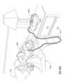
4.2 治療システム
1つの形態において、本技術は、呼吸障害の治療のための装置またはデバイスを含む。装置またはデバイスは、加圧空気を患者インターフェース3000への空気回路4170を介して患者1000へ供給するRPTデバイス4000を含み得る。4.2 Treatment Systems In one form, the present technology includes an apparatus or device for the treatment of breathing disorders. The apparatus or device may include an
4.3 患者インターフェース
本技術の一態様による非侵襲的患者インターフェース3000は、以下の機能様態を含む:シール形成構造3100、プレナムチャンバ3200、位置決めおよび安定化構造3300、通気孔3400、空気回路4170への接続のための一形態の接続ポート3600、および前額支持部3700。いくつかの形態において、機能様態が、1つ以上の物理的コンポーネントによって提供され得る。いくつかの形態において、1つの物理的コンポーネントは、1つ以上の機能様態を提供し得る。使用時において、シール形成構造3100は、気道への陽圧での空気供給を促進するように、患者の気道の入口を包囲するように配置される。4.3 Patient Interface A
患者インターフェースが最低レベルの陽圧を快適に気道へ送達できない場合、患者インターフェースは呼吸圧力治療に不適切であり得る。 A patient interface may be unsuitable for respiratory pressure therapy if the patient interface is unable to comfortably deliver minimal levels of positive pressure to the airways.
本技術の一形態による患者インターフェース3000は、周囲に対して少なくとも6cmH2Oの陽圧で空気供給を提供できるように構築および配置される。A
本技術の一形態による患者インターフェース3000は、周囲に対して少なくとも10cmH2Oの陽圧で空気供給を提供できるように構築および配置される。A
本技術の一形態による患者インターフェース3000は、周囲に対して少なくとも20cmH2Oの陽圧で空気供給を提供できるように構築および配置される。A
4.3.1 シール形成構造
本技術の一形態において、シール形成構造3100は、目標シール形成領域を提供し、クッション機能をさらに提供し得る。目標シール形成領域は、シール形成構造3100において密閉が発生し得る領域である。密閉が実際に発生する領域(すなわち、実際の密閉面)は、一定範囲の要素(例えば、顔面上の患者インターフェースの配置位置、位置決めおよび安定化構造における張力、および患者の顔の形状)に応じて、所与の治療セッションにおいて患者によって日々変化し得る。4.3.1 Seal-Forming Structure In one form of the present technology, the seal-forming
一形態において、目標シール形成領域が、シール形成構造3100の外面上に配置される。 In one form, a target seal-forming region is located on the outer surface of the seal-forming
本技術の特定の形態において、シール形成構造3100は、生体適合性材料(例えば、シリコーンゴム)から構成される。 In certain forms of the present technology, seal-forming
本技術によるシール形成構造3100は、柔らかく、可撓性でありかつ弾力性のある材料(例えば、シリコーン)から構成され得る。 A seal-forming
本技術の特定の形態において、1つよりも多くのシール形成構造3100を含むシステムが提供される。各シール形成構造3100は、異なるサイズおよび/または形状範囲に対応するように構成される。例えば、システムは、小さなサイズの頭ではなく大きなサイズの頭に適したシール形成構造3100の一形態および大きなサイズの頭ではなく小さなサイズの頭に適した別のものを含み得る。 In certain forms of the present technology, systems are provided that include more than one seal-forming
4.3.1.1 密閉機構
一形態において、シール形成構造は、圧力アシスト密閉機構を用いる密閉フランジを含む。使用時において、密閉フランジは、プレナムチャンバ3200内のシステム陽圧に容易に応答してその下側上に作用して、面と緊密な密閉係合を形成させ得る。圧力アシスト機構は、位置決めおよび安定化構造における弾性張力と共に作用し得る。4.3.1.1 Sealing Mechanism In one form, the seal-forming structure includes a sealing flange that uses a pressure assisted sealing mechanism. In use, the sealing flange may readily respond to positive system pressure within the
一形態において、シール形成構造3100は、密閉フランジおよび支持フランジを含む。密閉フランジは、厚さが約1mm未満(例えば、約0.25mm~約0.45mm)の比較的肉薄の部材を含む。この部材は、プレナムチャンバ3200の縁部長さの周囲に延びる。支持フランジは、密閉フランジよりも比較的肉厚であり得る。支持フランジは、密閉フランジと、プレナムチャンバ3200の周縁部との間に配置され、周辺長さの周囲の少なくとも一部に延びる。支持フランジは、バネ様要素であるかまたはバネ様要素を含み、密閉フランジを使用時に座屈しないように支持するよう機能する。 In one form, seal-forming
一形態において、シール形成構造は、圧縮密閉部またはガスケット密閉部を含み得る。使用時において、圧縮密閉部またはガスケット密閉部は、例えば位置決めおよび安定化構造における弾性張力に起因して圧縮状態となるように、構築および配置される。 In one form, the seal-forming structure may include a compression seal or a gasket seal. In use, the compression seal or gasket seal is constructed and arranged so that it is in compression, for example due to elastic tension in the positioning and stabilizing structure.
一形態において、シール形成構造は、張力部を含む。使用時において、張力部は、例えば密閉フランジの隣接領域により、ぴんと張られた状態で保持される。 In one form, the seal-forming structure includes a tension section. In use, the tension section is held taut, for example by the adjacent area of the sealing flange.
一形態において、シール形成構造は、粘着面または接着面を有する領域を含む。 In one form, the seal-forming structure includes a region having an adhesive or bonding surface.
本技術の特定の形態において、シール形成構造は、圧力アシスト密閉フランジ、圧縮密閉部、ガスケット密閉部、張力部、および粘着面または接着面を有する部位のうち1つ以上を含み得る。 In certain forms of the present technology, the seal-forming structure may include one or more of a pressure-assisted sealing flange, a compression seal, a gasket seal, a tension section, and a portion having an adhesive or bonding surface.
4.3.1.2 鼻梁または鼻堤領域
一形態において、非侵襲的患者インターフェース3000は、使用時に患者の顔の鼻梁領域上にまたは鼻堤領域上に密閉を形成するシール形成構造を含む。4.3.1.2 Nasal Bridge or Nasal Ridge Region In one form, the
一形態において、シール形成構造は、使用時において患者の顔の鼻梁領域上または鼻堤領域上にシールを形成するように構築されたサドル状領域を含む。 In one form, the seal-forming structure includes a saddle-like region configured to form a seal on the nasal bridge region or ridge region of a patient's face in use.
4.3.1.3 上唇領域
一形態において、非侵襲的患者インターフェース3000は、患者の顔の上唇領域(すなわち、上唇)上に使用時に密閉を形成するシール形成構造を含む。4.3.1.3 Upper Lip Region In one form, the
一形態において、シール形成構造は、使用時において患者の顔の上唇領域上にシールを形成するように構築されたサドル状領域を含む。 In one form, the seal-forming structure includes a saddle-like region configured to form a seal over the upper lip region of a patient's face in use.
4.3.1.4 顎領域
一形態において、非侵襲的患者インターフェース3000は、使用時に患者の顔の顎領域上に密閉を形成するシール形成構造を含む。4.3.1.4 Jaw Region In one form, the
一形態において、シール形成構造は、使用時において患者の顔の顎領域上にシールを形成するように構築されたサドル状領域を含む。 In one form, the seal-forming structure includes a saddle-like region configured to form a seal over the chin region of a patient's face in use.
4.3.1.5 前額領域
一形態において、シール形成構造は、シール使用時において患者の顔の前額領域上にシールを形成する。このような形態において、プレナムチャンバは、使用時において眼を被覆し得る。4.3.1.5 Forehead Region In one form, the seal-forming structure forms a seal on the forehead region of the patient's face during use of the seal. In such a configuration, the plenum chamber may cover the eye in use.
4.3.1.6 鼻枕
一形態において、非侵襲的患者インターフェース3000のシール形成構造は、一対の鼻パフまたは鼻枕を含む。各鼻パフまたは鼻枕は、患者の鼻の各鼻孔とのシールを形成するように構成および配置される。4.3.1.6 Nasal Pillows In one form, the seal-forming structure of the
本技術の一態様による鼻枕は、円錐台を含む。円錐台のうち少なくとも一部は、患者の鼻の下側、柄部、円錐台の下側上の可撓性領域上に密閉を形成し、円錐台を柄部へ接続させる。加えて、本技術の鼻枕が接続される構造は、柄部のベースに隣接する可撓性領域を含む。可撓性領域は、自在接合構造を促進するように機能し得る。自在接合構造は、円錐台の変位および角度双方と、鼻枕が接続される構造との相互移動に対応する。例えば、円錐台は、柄部が接続された構造に向かって軸方向に変位し得る。 A nasal pillow according to one aspect of the present technology includes a truncated cone. At least a portion of the frustum forms a seal over the underside of the patient's nose, the stem, and a flexible region on the underside of the frustum, connecting the frustum to the stem. Additionally, the structure to which the nasal pillows of the present technology are connected includes a flexible region adjacent the base of the shank. The flexible region may function to facilitate a flexible joint structure. The universal joint structure accommodates both the displacement and angle of the truncated cone and its relative movement with the structure to which the nasal pillows are connected. For example, the truncated cone may be axially displaced toward the structure to which the shank is connected.
4.3.2 プレナムチャンバ
プレナムチャンバ3200は、使用時に密閉が形成される領域において平均的な人の顔の表面外形に対して相補的である形状の周囲を有する。使用時において、プレナムチャンバ3200の周辺縁部は、顔の隣接する表面に近接して位置決めされる。顔との実際の接触は、シール形成構造3100によって提供される。シール形成構造3100は、使用時においてプレナムチャンバ3200の縁部全体の周りに延び得る。いくつかの形態において、プレナムチャンバ3200およびシール形成構造3100は、単一の均質的材料ピースから形成される。4.3.2 Plenum Chamber The
本技術のいくつかの形態において、プレナムチャンバ3200は、使用時において患者の眼を被覆しない。換言すると、眼は、プレナムチャンバによって規定される加圧空間外にある。このような形態の場合、押しつけがさが低減しかつ/またはより着用者の快適性が増すことが多いため、治療コンプライアンスが向上し得る。 In some forms of the present technology,
本技術の特定の形態において、プレナムチャンバ3200は、透明材料(例えば、透明ポリカーボネート)から構築される。透明材料の利用により、患者インターフェースの押しつけがましさが低減され得、治療へのコンプライアンスの向上が補助され得る。透明材料の利用により、臨床医が患者インターフェースの配置様態および機能を確認することが補助され得る。 In certain forms of the present technology,
本技術の特定の形態において、プレナムチャンバ3200は、半透明材料から構成される。半透明材料を用いることにより、患者インターフェースの押しつけがましさを低減することができ、治療へのコンプライアンスの向上を補助することができる。 In certain forms of the present technology,
4.3.3 位置決めおよび安定化構造
本技術の患者インターフェース3000のシール形成構造3100は、使用時において位置決めおよび安定化構造3300によって密閉位置において保持され得る。4.3.3 Positioning and Stabilizing Structure The seal-forming
一形態において、位置決めおよび安定化構造3300により、顔から浮き上がるためのプレナムチャンバ3200中の陽圧の効果に打ち勝つのに少なくとも充分な保持力が得られる。 In one form, the positioning and stabilizing
一形態において、位置決めおよび安定化構造3300により、患者インターフェース3000上への引力に打ち勝つだけの保持力が得られる。 In one form, the positioning and stabilizing
一形態において、位置決めおよび安定化構造3300により、患者インターフェース3000上への破壊的作用の可能性(例えば、管引き摺りまたは患者インターフェースとの不慮の干渉に起因するもの)を解消するための安全マージンとして保持力が得られる。 In one form, the positioning and
本技術の一形態において、患者が睡眠時に装着されるように構成された位置決めおよび安定化構造3300が提供される。一実施例において、位置決めおよび安定化構造3300は、装置の感知される嵩または実際の嵩を低減するように、目立たない外形または断面厚さを有する。一実施例において、位置決めおよび安定化構造3300は、矩形断面を有する少なくとも1つのストラップを含む。一実施例において、位置決めおよび安定化構造3300は、少なくとも1つの平坦ストラップを含む。 In one form of the present technology, a positioning and stabilizing
本技術の一形態において、患者が患者の頭部の後部領域を枕に載せた状態で仰臥位睡眠位置において寝る際の妨げとなるような過度に大きいまたは嵩張るサイズにならないように構成された位置決めおよび安定化構造3300が提供される。 In one form of the present technology, the positioning is configured such that the patient is not of excessively large or bulky size that would interfere with sleeping in a supine sleep position with the posterior region of the patient's head resting on a pillow. and a stabilizing
本技術の一形態において、患者が患者の頭部の側部領域を枕に載せた状態で側臥位睡眠位置において寝る際の妨げとなるような過度に大きいまたは嵩張るサイズにならないように構成された位置決めおよび安定化構造3300が提供される。 In one form of the present technology, the patient is configured to not be of excessively large or bulky size so as to interfere with sleeping in a lateral sleeping position with the lateral areas of the patient's head resting on the pillow. A positioning and stabilizing
本技術の一形態において、位置決めおよび安定化構造3300は、位置決めおよび安定化構造3300の前方部位と位置決めおよび安定化構造3300の後方部位との間に配置された結合解除部を備える。この結合解除部は、圧縮に耐えず、例えば可撓性またはぺらぺらのストラップであり得る。結合解除部位は、患者が頭を枕に載せて横たわったときに結合解除部位の存在により後方部位への力が位置決めおよび安定化構造3300に沿って伝達されてシールが妨害される事態を回避できるように、構築および配置される。 In one form of the present technology, the positioning and stabilizing
本技術の一形態において、位置決めおよび安定化構造3300は、布地患者接触層、発泡材料内側層および布地外側層の積層物から構成されたストラップを含む。一形態において、発泡材料は、湿気(例えば、汗)がストラップを通過できるような多孔性である。一形態において、織物外側層は、フック材料部分と係合するループ材料を含む。 In one form of the present technology, the positioning and stabilizing
本技術の特定の形態において、位置決めおよび安定化構造3300は、伸張可能である(例えば、弾力性と共に伸張可能である)ストラップを含む。例えば、ストラップは、使用時にはピンと張った状態にされて、シール形成構造を患者の顔の一部と密着させる力を方向付けるように、構成され得る。一実施例において、ストラップは、タイとして構成され得る。 In certain forms of the present technology, positioning and stabilizing
本技術の一形態において、位置決めおよび安定化構造は第1のタイを含み、第1のタイは、使用時においてその下縁部の少なくとも一部が上を通過して患者の頭の耳基底上点へ移動し、後頭骨を被覆することなく頭頂骨の一部を被覆するように、構築および配置される。 In one form of the present technology, the positioning and stabilizing structure includes a first tie that, in use, has at least a portion of its lower edge passing over the base of the ear on the patient's head. It is constructed and positioned to move to a point and cover part of the parietal bone without covering the occipital bone.
鼻専用マスクまたはフルフェイスマスクに適した本技術の一形態において、位置決めおよび安定化構造は、第2のタイを含む。第2のタイは、使用時においてその上縁部の少なくとも一部が患者頭部の下側の耳基底下点の下側を通過し、患者頭部の後頭骨を被覆するかまたは患者頭部の後頭骨の下側に載置されるように、構築および配置される。 In one form of the technology suitable for nasal-only or full-face masks, the positioning and stabilizing structure includes a second tie. The second tie, in use, has at least a portion of its upper edge passing under the subauricular point on the underside of the patient's head, and covers or covers the occipital bone of the patient's head. It is constructed and placed so that it rests on the underside of the occipital bone.
鼻専用マスクまたはフルフェイスマスクに適した本技術の一形態において、位置決めおよび安定化構造は、第1のタイおよび第2のタイが相違に離隔方向に移動する傾向を低減させるように第1のタイおよび第2のタイを相互接続させるように構築および配置された第3のタイを含む。 In one form of the present technology, suitable for a nasal-only mask or a full-face mask, the positioning and stabilizing structure is configured to reduce the tendency of the first tie and the second tie to move apart in different directions. A third tie is constructed and arranged to interconnect the tie and the second tie.
本技術の特定の形態において、位置決めおよび安定化構造3300は、屈曲可能であり例えば非剛性であるストラップを含む。本態様の利点として、患者が睡眠時に体を横たえたときにストラップがより快適になっている点がある。 In certain forms of the present technology, positioning and stabilizing
本技術の特定の形態において、位置決めおよび安定化構造3300は、内部を水蒸気が通過できるように呼吸可能なように構成されたストラップを含む。 In certain forms of the present technology, positioning and stabilizing
本技術の特定の形態において、1つよりも多くの位置決めおよび安定化構造3300を含むシステムが提供される。各位置決めおよび安定化構造3300は、異なるサイズおよび/または形状範囲に対応するための保持力を提供するように構成される。例えば、システムは、小さなサイズの頭ではなく大きなサイズの頭に適しかつ大きなサイズの頭ではなく小さなサイズの別の頭に適した位置決めおよび安定化構造3300の一形態を含み得る。 In certain forms of the present technology, systems are provided that include more than one positioning and stabilizing
4.3.4 通気
一形態において、患者インターフェース3000は、吐き出されたガス(例えば、二酸化炭素)の押し出しを可能にするように構成および配置された通気部3400を含む。4.3.4 Ventilation
In one form,
特定の形態において、通気3400は、プレナムチャンバ内の圧力が雰囲気に対して正であるときにプレナムチャンバ3200の内部から雰囲気への連続的通気流れを可能にするように構成される。通気部3400は、使用時においてプレナムチャンバ内の治療圧力を維持しつつ、通気流量の大きさが呼気されたCO2の患者による再呼吸を低減できるだけの充分な大きさになるように、構成される。In certain forms,
通気部3400は様々な形をとることができる。一形態おいて、本技術による通気部3400は、複数の穴(例えば、約20個~約80個の穴、または約40個~約60個の穴、または約45個~約55個の穴)を含む。各穴部のサイズは0.5~1mmであり得、好適には0.6~0.9mmであり得、より好適には0.7~0.8mmであり得る。穴部は通常は円形の開口部と共に形成されるが、他の形状も可能である。複数のより小さな穴部を、1つ以上のより大きな穴部と交換してもよい。より大きな穴部のうちいくつかは、スリットの形態を有し得る。
通気部3400は、プレナムチャンバ3200内に、あるいはエルボー3600内に配置されかつ一体化され得る。あるいは、通気部3400は、結合解除構造(例えば、スイベル)として別個に形成され得、空気回路4170の一部として配置してもよいし、あるいは、空気回路4170とプレナムチャンバ3200との間に設けてもよい。
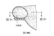
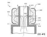
図4Aは、通気部3400(例えば、ガス洗い流し通気部)の実装例を示す。図4Aは、通路3402、壁部3404、拡散材3406およびハウジング3408を通じた断面図である。これらはそれぞれ、中央空気通路3410の周囲に設けられる。空気通路3410は、プレナムチャンバ3200への入口(例えば、結合解除構造の一部)であってもよいし、あるいは空気回路4170の一部であってもよい。図示の断面は、中央空気通路3410の周囲において一定量の対称性を含むが、対称性は不要である。 FIG. 4A shows an example implementation of a vent 3400 (eg, a gas flush vent). FIG. 4A is a cross-sectional view through
拡散材3406は、隙間3412によって壁部3404から離隔して配置されるため、通路3402と開口部3416との間に途切れない流体連通を提供する通路が得られる。これは、(拡散材3406の表面3414が開口部3420の表面に対向するように)ハウジング内に拡散材を少なくとも部分的に配置することにより、可能になる。拡散材の表面3414は、実質的に平面状の表面であり、隙間3412により開口部3420の表面から離隔して配置される。この構成は、開口部3420全ての間と、開口部3420および開口部3416全ての間とに流体連通が可能なように隙間が延びるような構成である。
開口部3416により、雰囲気との連通が可能になる。隙間のサイズについては、隙間中に蓄積された粉塵全てを清浄にしかつ蓄積された水分全てを乾燥させることができるようなサイズにすべきである。よって、隙間3412の深さは1~3mmであり得、好適には1.5~2.5mmであり得、より好適には約2mmであり得る。本記載中に後述するように、配置構成は、患者インターフェースの標準的動作時において、通路3402から退出する少なくとも一定の加圧空気(例えば、ジェットまたは圧力波)が隙間3412を埋めて拡散材3406に進入するような配置構成にされる。気流が拡散材に進入すると、材料の特性により、気流は蛇行経路上に強制移動する。隙間3412を介してより低い抵抗の経路が存在する場合も、拡散材3406内に空気は進入し得るが、音速または音速に近い速度であり得るジェット空気を付与すると、空気上に充分なモメンタムが付与されて、少なくとも一定の分子が拡散材に進入する。
拡散材3406の特性(例えば、厚さまたは密度)および開口部3424のサイズは、気流全体に対する開口部3424の影響が無視できるくらいの大きさになるように、選択される。また、第2の壁部3428は、拡散材3406について通路3402に直接対向する。ハウジング3408は、この対向側上の気流に対して本質的に閉鎖される。そのため、拡散材3406に進入した気流は、最終的に隙間3412中へと強制的に返送され、開口部3416を介して周囲空気へ退出する。通気部の上記構成上により気流上に実質的に強制移動される蛇行路により、ジェット効果および/または通気部と関連付けられたジェット効果によって発生するノイズが低下する。代替的にまたは追加的に、拡散材3406により隙間3412の少なくとも片側が規定されるため、隙間を伝播する音波は全て、拡散材3406中に拡張することができ、拡散材3406そのものを通過する実質的気流がほとんど無い場合でも、音レベルが低下する。 The properties of the diffusion material 3406 (eg, thickness or density) and the size of the
図示のように、隙間3412は全て、拡散材3406の表面3414に沿って開口部3416へ延びるが、隙間3412を長さ全体に沿って延ばす必要が無い。例えば、部位3418においては隙間は発生し得ない(例えば、空気通路3410に最も近い通路3402の内部は、図示の実装例においてラジアル方向に内方に設けられる)。通路3402から開口部3416への途切れない経路を提供する隙間3412の他の構成を設けてもよい。 As shown, all of the
隙間3412の存在により、隙間の無い通気部を比較して、通気部3400の性能特性を向上させることが可能になる。例えば、拡散材3406に適したいくつかの材料の場合、一貫した密度および通気性と共に製造することが困難なことがある。その結果、異なる患者インターフェースの通気部を通過する洗い流し気流の不要な変動に繋がり得る。隙間を設けることにより、恒久的な逃げ経路が得られ、その結果、洗い流し流れをより一貫させかつ/または予測可能にすることが可能になる。この隙間により、拡散材3406を通過する気流が任意の理由(例えば、材料3406が湿潤した場合)において低減または回避されるというさらなる利点が得られる。この場合、隙間3412により、空気を雰囲気へ移動させるための逃げ経路が得られる。 The presence of the
壁部3404により、拡散材3406は、使用時に治療圧力に晒される患者インターフェース3000の内部から分離される。通路3402は、壁部3404を貫通し、拡散材3406に隣接しかつ対向する各開口部3420を含むものとして図示される。通路3402は任意の数でよく、通気部3400の所望の流れ特性を可能にする任意の幾何学的構成のいずれかでよい。例えば、通路は、通気部3400の所望の性能特性を可能にする形状であれば、円筒型通路、円錐台状通路および/または他の任意の三次元形状(例えば、スロット)でよい。図4Aにおいて、通路は、下方にテーパー状にされた開口部が拡散材へ方向付けられた円錐台形状であるが、必ずしもそうでなくてよく、円錐台形状の下方にテーパー状にされた開口部を反対方向に方向付けてもよい。これらの構成のうちいずれかまたは全てはにより、治療圧力へ晒されるように構成された患者インターフェース3000の内部との流体連通が可能になり得る。単一の通路3402を設けてもよいし、あるいは、複数を設けてもよい。しかし、複数を設けた場合、任意の生成された可聴音が低減し得る。通路3402は、受動的なものであってもよいし、あるいは、弁システム(図示せず)の一部として、治療圧力などの条件に基づいて通路を通過する流れを調整してもよい。開口部3420および/または通路3402のサイズと、開口部3420および拡散材3406の方向付けとについては、(患者インターフェース3000の内部が治療圧力に晒されたときに)開口部3420から退出する空気が表面3414において拡散材3406に衝突するようなサイズおよび方向付けにされる。開口部3420から退出した空気は、内部が治療圧力よりも低い圧力に晒されたときにも衝突し得る。この構成により、患者インターフェース3000の内部が治療圧力に晒されたとき、開口部3420から退出する空気のうち少なくとも一部が拡散材3406を貫通し得、表面3414から退出した後、開口部3416を介して通気部から退出する。拡散材3406を貫通するが表面3414から退出しない空気の任意の部分は、ハウジング3408中の漏洩に起因して、拡散材3406から退出し得る。この流れ構成により、通気部3400から退出するガスの流路全体がより断面図構成より蛇行状(tortious)になり得るため、発生したノイズが減衰するかまたは排除される可能性が高まる。速度が充分に低くかつ表面3414の多孔性に起因して表面効果により空気の貫通が妨げられる場合、空気は衝突はするが貫通はし得ない。このシナリオにおいて、拡散材3406を用いると、音波を拡散材3406中に伝搬および拡散させることが可能になるため、ジェット効果の低減およびノイズ低減が可能になり得る。
拡散材3406により、空気が材料を通過する際に空気が拡散するため、エネルギーの吸収および/または空気速度の低下が可能になり得る。流れ速度が低下すると、(乱流または空気ジェットが硬質の表面に衝突することに起因することが多い)関連ノイズも低減する。拡散材3406は、フィルタ媒体(例えば、未圧縮の繊維(例えば、ポリエステル繊維))または連続気泡フォームにおいて用いられるものと同様の繊維材料であり得る。空気流れの少なくとも部分的貫通と、材料内を流れる空気のための蛇行状経路とを可能にする任意の材料が、拡散材3406のために用いられ得る。拡散材は、焼結プラスチックなどの吸湿材料であり得る。拡散材は疎水性であってもよく、抗菌性を有するように処理され得る。これらの構成のうち1つ以上により、水分除去が支援され得、クリーニング時において有用であり得る。
ハウジング3408は、(通気部3400の所望の流れ特性も可能にしつつ)拡散材3406を所定位置に保持することを支援する任意の形状を有し得る。ハウジング3408は、開口部3420それぞれに直接対向する全領域においてハウジングから流出する流れを回避する壁部構成を含むものとして図示される。ハウジング3408は、拡散材3406を包囲する構造的コンポーネント(例えば、記壁部3404および壁部3428)全てを含み得る。中心線3430は、通路3402それぞれの中心軸に沿って図示され、第2の壁部3428へ延びる。これらの通路が入口流れ条件に相対して充分に長い場合、充分に発達した流れが発生し、矢印3422は、通路3402から退出する流れベクトルの近似である。流体流れの無秩序性に起因して、流れが通路3402から離隔方向に移動する際に実際の流れが分岐および放散し得る。しかし、所与のポイントにおける流れの特徴付けのために、ベクトル(例えば、大きさおよび方向)が用いられ得る。これらのベクトルが伸長すると、最終的には、開口部を含まないハウジングの一部3408と交差する。しかし、流れ方向に延びた場合に固形壁部に遭遇するのは、各開口部の中心軸に沿って概して延びる流れベクトルだけではない。開口部3420それぞれの断面領域は、各中心線3430に沿って突出され、領域の画像が、壁部3428中の開口部の代わりに壁部3428の固形部位上に突出される。そのため、ハウジング3408または通気部3400内の開口部(例えば、第2の開口部3416)が出口ベクトルと一列になるかまたは通路3402のいずれかからの突出領域と重複することは無いため、通路3402から退出する空気は、通路3402に直接対向する第2の壁部3428の一部から通気部3400を退出することはできない。その代わりに、出口開口部3416は、通路3402の流れベクトルに対して角度を以て設けられた方向に延びる。この角度は鋭角であり得るが、いくつかの例において、直線状(例えば、出口ベクトルに対して直角である)かまたはさらには鈍角である。このような構成により、通路3402から退出する空気が拡散材3406を通じて蛇行状経路に追随して、開口部3416を通じて通気部3400から退出する可能性が高くなる。上記したように、出口開口部3416は、以下のうち1つ以上によって規定され得る:ハウジング3408の壁部、拡散材の表面または別のコンポーネントの表面。出口開口部3416は、空気が拡散材3406を通過しない経路に沿って周囲環境中に解放される限り、任意の方向に方向付けられ得る。1つの別の例において、出口開口部3416からの流れは、矢印3422に対して平行であってもよいし、あるいは矢印3422からオフセットしてもよい。
図示のように、ハウジング3408は開口部3416を部分的に境界付け、壁部3404も開口部3416を部分的に境界付けるが、開口部3416は、ハウジング3408によって完全に境界付けてもよいし、あるいはハウジング3408によって全く境界付けられていなくてもよい。後者の場合、開口部3416は、例えばハウジング3408ではなくコンポーネントによって規定され得る。適切な流路(例えば、隙間3412)を提供する開口部3416の任意の構成および場所が用いられ得る。図示のように、開口部3416は、通気部3400の周囲全体を包囲する環状の隙間であるが、開口部3416は、任意の数の開口部であってもよい。例えば、その結果得られる開口部の安定性を増加させるために、開口部3416を複数の開口部に分割することが望ましい場合がある。図示のように、開口部3416は、周囲への直接的出口として記載され得るが、開口部3416は、より間接的なまたはより蛇行状経路として周囲へ延び得る。例えば、さらなる構造的要素を設けることにより、周囲への退出前に1つ以上の旋回部を含む流路が設けられ得る。また、開口部3416は、隙間3412または壁部3404に対して図示以外の方向に設けられ得る。図示のように、開口部3416を貫通する流路は、通路3402および/または矢印3422に対して実質的に直角であるが、開口部は、別の角度または方向付けをとり得る。例えば、開口部を貫通する流路は、通路3402に対して鈍角または鋭角をとってもよいし、あるいは、通路3402に対して平行であるかまたは通路3402からオフセットしてもよい。 As shown, the
ハウジング3408は、通路3402と一列になっていない開口部3424も含み得る。開口部3424の方向付けを視覚的に明確にするために、開口部3424は、開口部3424の中心軸上の中心線3432と共に図示される。通路3402の中心線3430は、開口部3424の中心線3432と整合されない。通気部3400のクリーニング後に水分除去が可能になるように、開口部3424が任意選択的に設けられ得る(ゼロ、1つ以上が設けられ得る)。開口部3424により、水が通気部3400から振り落とされることおよび/または水が蒸発して通気部3400から退出する可能性が高まることが可能になり得、振り落としおよび蒸発はどちらとも、通気部3400の乾燥に貢献する。開口部3424が設けられる場合、開口部3424は好適には、拡散材3406、開口部3416および隙間3412と関連して、(患者インターフェース3000へ治療圧力が付加されたときに)開口部3424から退出する空気が実質的に無くなるような配置およびサイズにされる。開口部3424からの流れを決定するために、圧力が患者インターフェース3000へ付加され得、通気部3400を通じた流量が測定される。次に、開口部3424は完全に遮断され得、流量が再度測定され得る。流量低下量が所定のパーセンテージ未満である場合、通気部3400を通過する空気流れに実質的低下は無い。好適には、流量低下量は5%を超えず、より好適には流量低下量は3%を超えない。実際、開口部3424を遮断しても、通気部3400を通過する流量に変化は無い。開口部3424を完全に遮断すると通気部3400を通過する流れが実質的に無くなるように通気部3400を設計することにより、拡散材3406が完全に詰まった場合(これは、水または粘液の蓄積に起因して発生し得る)でも、通気部3400により充分なガス洗い流しが得られるはずである。
開口部3424は、(開口部3420に対向する側と反対側の)拡散材3406に隣接する領域内に形成され得る。しかし、開口部3424のサイズおよび場所は変化し得る。開口部3424は、少なくとも2つの目的(すなわち、通気部の洗浄および乾燥)を有し得る。第1に、開口部3424により、ユーザが通気部3400全体を水栓からの水の下に配置することにより、拡散材3406を洗い流すことが可能になり得る。洗い流しを有効にするために、開口部3424は好適には、液体の水(例えば、液滴)がハウジングに進入できるような充分な大きさであるとよい。第3の、開口部3424により、洗浄後または通気部の使用時に液体(例えば、粘液、水)が意図せず蓄積した後に、蓄積した液体を除去することが可能になり得る。各単一の開口部3424のサイズは、液体(例えば、水)のイベントにおける流入および流出を可能にする能力に関連する。開口部全てのサイズの組み合わせにより、通気部の洗浄および乾燥の効率が決定され得る。20mm2~80mm2の組み合わされた領域を用いると、適切な洗浄および乾燥が可能になると考えられる。いくつかの例において、開口部領域全体は好適には30~60mm2であり、さらに好適には約50mm2である。開口部の場所も重要であり得る。開口部3424は、拡散材3406について(少なくとも一定範囲において)開口部3416と反対側に間隔を空けて配置されると好適である。その結果、開口部3416および3424間に水または液体の流路が得られるため、拡散材3406を洗浄および乾燥する能力が向上する。少なくとも図4Aに示す実施形態を用いれば、振り落としまたは通気部3400への求心力付加により、少なくとも第2の開口部3424を通じて水を除去することができる。The
ハウジング3408は、任意の適切な方法により拡散材3406を所定位置に保持し得る。例えば、ハウジング3408および拡散材3406は、共に接合(例えば、共に接着または溶解させてもよいし)あるいは機械的に締結(例えば、摩擦、干渉、戻り止め)してもよい。
ハウジング3408は、単一の一体ピースまたは複数のピースであってもよいし、あるいは、複数のピースを共に接合して単一のピースとしてもよい。壁部3404は、ハウジング3408に恒久的に接合してもよいし、あるいはハウジング3408と一体形成してもよい。ハウジングは、解放不可能な様態で通気部3400へ取り付けられ得る。これは、破壊無しに取り外されることを意図していない取付けである。解放不可能な取付けを挙げると、接着剤、超音波溶接、焼き鏝による溶解、例えばもともとはワンピースとして形成されたワンタイムスナップ嵌め(例えば、分離されたときに破壊されるように設計されたスナップ嵌め)がある。ハウジング3408および/または拡散材3406を取り外しできないようにハウジング3408が形成されている場合、いくつかの恩恵が達成され得る。例えば、ハウジング3408および/または拡散材3406を取り外しできない場合、通気部をユーザが不正確または意図せず取り外す事態を回避することができる。
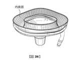
図4Bは、通気部3400の別の構成を示す。図4Aの参照符号に関連する記載はここでも適用可能であるため、説明を控える。通気部3400のこの構成は、空気通路3410が省略されている点を除いて図4Aに示すものに類似する。そのため、隙間3412は、通気部3400の片側から他方側へ延びる。 FIG. 4B shows another configuration of the
図4Cは、通気部3400の別の構成を示す。図4Aの参照符号に関連する記載はここでも適用可能であるため、説明を控える。ここで、空気通路3410を省略している代わりに部材3426が図示される。部材3426は、拡散材3406および/またはハウジング3408を固定し得る。 FIG. 4C shows another configuration of the
図4Dは、通気部3400の別の構成を示す。図4Aの参照符号に関連する記載はここでも適用可能であるため、説明を控える。本図が図4Aと異なる点として、開口部3424の場所が異なる点がある。本図は、開口部3416が通気部3400の周囲全体において連続する連続する開口部であり得ることも示す。しかし、開口部3424も連続してもよいが、好適には相互にかつ/または開口部3416から不連続出会って方がよい。 FIG. 4D shows another configuration of the
図4Eは、通気部3400の別の構成を示す。図4Aの参照符号に関連する記載はここでも適用可能であるため、説明を控える。この構成において、通路3402は、空気通路3410と連通しかつ空気通路3410の周囲に整列されるため、図4A~図4Dの平面状構成と比較して全体的に環状の構成を有する通気部3400が得られる。換言すると、図4A~図4D中の通路3402は、1つの平面状のまたはほぼ平面状の壁部3404内に有る一方、図4E中の壁部3404は円筒型であり、通気部3400から退出するガスは、連続線によって示す円筒軸に沿って退出する。 FIG. 4E shows another configuration of the
図4Fは、通気部3400の別の構成を示す。図4Aの参照符号に関連する記載はここでも適用可能であるため、説明を控える。図4Fは、開口部3416が図4F中の拡散材3406の2つの端部に設けられておりかつ図4E中の一端のみに設けられている点を除いて、図4Eに類似する。 FIG. 4F shows another configuration of the
図4A~図4Fそれぞれにおいて、拡散材3406を通じて図示される矢印は、拡散材3406を通過する空気流れの概念図であり、拡散材3406を流れる実際の空気流れを示していない場合がある。一般的に、これらの矢印はそれぞれ、空気が通路3402から退出して表面3414を介して拡散材3406に進入し、表面3414を介して拡散材から退出し、隙間3412を通じて流れた後に開口部3416を介して周囲へ流出する概念を示す。 In each of FIGS. 4A-4F, the arrows illustrated through the diffusing
図4G~図4Iは、通気部3400の別の構成を示す。図4Aの参照符号に関連する記載はここでも適用可能であるため、注記を除いて説明を控える。図4Gは、通気部3400の例の斜視図である。通気部3400は、挿入可能かつ/または取り外し可能なアセンブリである。図4Hは、内部構造が見えるように上カバー3440が省略された平面図である。図4Iは、図4Hの横断面図ではあるが上部カバーが含まれたままである。通気部3400のこの構成は、空気通路3410が省略されている点において、図4Bに示すものに類似する(しかし、所望であれば設けてもよい)。図4I中に最良に示すように、支持部3434は、拡散材3406を支持するように、表面3414と接触する。図4Hおよび図4Iに示すように、支持部3434は、隙間3412を二等分する隣接する壁部として図示され、隣接して途切れずに延びる。しかし、支持部3434は、隣接する必要は無く、1つ以上の隣接しない支持部によって形成され得る(1つ以上の隙間が支持部3434内に設けられ得る)。 4G-4I illustrate another configuration of the
別の差として、開口部3416の位置がある。開口部3416は、実質的に隙間3412と一列に設けられる代わりに、開口部3420を含む表面から離隔方向にオフセットされ、その結果、隙間3412の第2の部位3412Aが拡散材3406の周囲を包囲する。この配置構成により、空気が表面3414中に流入し、拡散材3406の横表面3436から流出した後、開口部3416から流出することが可能になる。空気を拡散材3406を通過させること無く隙間3412および第2の部位3412Aを通過させることも可能である。個々の分子の流れは無秩序かつ予測不可能であるため、実際の空気流れは、双方の流路の組み合わせであり得る。しかし、双方の流路を提供することにより、通気部3400は、拡散材3406が詰まったときでも適切な流れを提供し得る。 Another difference is the location of opening 3416.
図4Gおよび図4Iは、溝部3438を通気部3400の周囲に示す。このような溝部により、通気部3400を噛み合い穴部内に(好適には交換可能な様態で)保持することが可能になり得る。例えば、穴部が比較的可撓性の材料(例えば、シリコーン)によって構成される場合、通気部3400を容易に取り外しすることができるため、クリーニングまたは交換などの作業を1回で行うことが可能になる。 4G and 4I show a
図4Jおよび図4Kは、図4Iに類似する態様を示すが、偏向器3442が追加されている点において異なる。図4Jにおいて、偏向器3442は、固形の平坦な障害物として図示されており、これにより、空気が拡散材3406を通じて壁部3428へ直接流れること(例えば、表面3414から反対側へ流出すること)が回避される。図4Kにおいて、偏向器3442は曲線状になっているため、図4Jに示す平坦な偏向器の場合よりも拡散材3406の側部からより円滑な移行を生成し得る。偏向器3442の複数のピースを図4K中に示しているが、所望の流れ特性の達成に必要な任意の数のピース(例えば、単一のピース)が用いられ得る。双方のバージョンの偏向器3442において、偏向器3442を拡散材3406内に生成するための任意の適切な方法が用いられ得る。例えば、適切な形状の切り込みを拡散材3406の側部に設ければ、偏向器3442の挿入が可能になり得る。あるいは、拡散材3406を複数のピースから構成して、拡散材3406の周囲に接合してもよい。 4J and 4K show aspects similar to FIG. 4I, except that a
一態様において、拡散材3406は、取り外し可能であり得る。例えば、カバー3440を解放可能な様態で取り付けた場合、カバー3440を介した機械的保持を通じて拡散材3406を保持することができる。カバー3440が取り外されると、拡散材3406も取り外し可能となる。しかし、別の態様において、拡散材3406は取り外し不可能であり得る。例えば、通気部3400を損壊しないとカバー3440を取り外せないようにカバー3440が通気部3400へ取り付けられている場合、拡散材3406は取り外し不可能とみなされ得る。あるいは、拡散材3406を通気部3400内に恒久的に(例えば接着剤により)取り付けてもよく、その場合、拡散材3406は取り外し時に損壊される。カバー3440が損壊無しに取り外し可能であっても、拡散材3406を拡散材3406を損壊または破壊する様態で固定することができるため、拡散材3406は取り外し不可能となる。 In one aspect, diffusing
拡散材3406の境界を表面3414として記述したが、これは、固形本体の表面と異なり得る。拡散材3406は、蛇行状の流れが拡散材を通過できるように、多数の開口部または隙間を有し得る。よって、表面3414は、拡散材3406の境界としてもみなされ得る。 Although the boundary of the
通気部3400は、比較的少量のノイズを生成し得るかまたはノイズを抑制し得、その後音波がユーザへ伝搬する。好適には、発生した音は、28dB(A)未満である。例えば、音は、20~28dB(A)、22~26dB(A)または約24dB(A)であり得る。これらの音レベルは、ユーザにも寝室パートナーにも妨害にならないような充分な低いレベルであり得る。 The
4.3.5 結合解除構造(複数)
一形態において、患者インターフェース3000は、少なくとも1つの結合解除構造(例えば、回り継ぎ手または球窩)を含む。4.3.5 Uncoupling structures (multiple)
In one form,
4.3.6 接続ポート
接続ポート3600は、空気回路4170への接続を可能にする。4.3.6 Connection port
4.3.7 前額支持部
一形態において、患者インターフェース3000は、前額支持部3700を含む。4.3.7 Forehead support
In one form,
4.3.8 窒息防止弁
一形態において、患者インターフェース3000は、窒息防止弁を含む。4.3.8 Anti-choking valve
In one form,
4.3.9 ポート
本技術の一形態において、患者インターフェース3000は、プレナムチャンバ3200内の量へのアクセスを可能にする1つ以上のポートを含む。一形態において、これにより、臨床医が補充酸素を供給することが可能になる。一形態において、これにより、プレナムチャンバ3200内のガス(例えば、圧力)の特性を直接測定することが可能になる。4.3.9 Port
In one form of the present technology,
4.4 用語集
本技術の開示目的のため、本技術の特定の形態において、以下の定義のうち1つ以上が適用され得る。本技術の他の形態において、別の定義も適用され得る。4.4 Glossary For purposes of disclosing the present technology, one or more of the following definitions may apply in certain forms of the present technology. In other forms of the technology, other definitions may also apply.
4.4.1 一般
空気:本技術の特定の形態において、空気は大気を意味し得、本技術の他の形態において、空気は、他の呼吸可能なガスの組み合わせ(例えば、酸素を豊富に含む大気)を意味し得る。4.4.1 General Air: In certain forms of the present technology, air may mean the atmosphere; in other forms of the technology, air may be a combination of other breathable gases (e.g. oxygen-enriched). atmosphere).
雰囲気:本技術の特定の形態において、「雰囲気」という用語は、(i)治療システムまたは患者の外部、および(ii)治療システムまたは患者を直接包囲するものを意味するものとしてとられるべきである。 Atmosphere: In certain forms of the present technology, the term "atmosphere" shall be taken to mean (i) external to the treatment system or patient, and (ii) directly surrounding the treatment system or patient. .
例えば、加湿器に対する雰囲気湿度とは、加湿器を直接包囲する空気の湿度であり得る(例えば、患者が睡眠をとっている部屋の内部の湿度)。このような雰囲気湿度は、患者が睡眠をとっている部屋の外部の湿度と異なる場合がある。 For example, the ambient humidity for a humidifier may be the humidity of the air directly surrounding the humidifier (eg, the humidity inside the room in which the patient is sleeping). Such ambient humidity may differ from the humidity outside the room in which the patient is sleeping.
別の実施例において、雰囲気圧力は、身体の直接周囲または外部の圧力であり得る。 In another example, the ambient pressure can be pressure directly surrounding or external to the body.
特定の形態において、雰囲気(例えば、音響)ノイズは、例えばRPTデバイスから発生するかまたはマスクまたは患者インターフェースから発生するノイズ以外の、患者の居る部屋の中の背景ノイズレベルとみなすことができる。雰囲気ノイズは、部屋の外の発生源から発生し得る。 In certain forms, atmospheric (eg, acoustic) noise may be considered the background noise level within the room in which the patient resides, other than noise generated from, for example, an RPT device or from a mask or patient interface. Ambient noise can originate from sources outside the room.
自動的な気道陽圧(APAP)療法:SDB発症の兆候の存在または不在に応じて、例えば、呼吸間に最小限界と最大限界との間で治療圧力を自動的に調節することが可能なCPAP療法。 Automatic positive airway pressure (APAP) therapy: CPAP that is able to automatically adjust the therapeutic pressure between minimum and maximum limits, e.g. between breaths, depending on the presence or absence of signs of developing SDB. Therapy.
持続的気道陽圧(CPAP)療法:治療圧力が患者の呼吸サイクルを通じてほぼ一定である呼吸圧療法。いくつかの形態において、気道への入口における圧力は、呼息時において若干上昇し、吸息時において若干低下する。いくつかの形態において、圧力は、患者の異なる呼吸サイクル間において変動する(例えば、部分的な上気道閉塞の兆候の検出に応答して増加され、部分的な上気道閉塞の通知の不在時において低減される)。 Continuous Positive Airway Pressure (CPAP) Therapy: Respiratory pressure therapy in which the therapeutic pressure remains approximately constant throughout the patient's breathing cycle. In some configurations, the pressure at the entrance to the airway increases slightly during exhalation and decreases slightly during inspiration. In some forms, the pressure varies between different breathing cycles of the patient (e.g., is increased in response to detection of signs of partial upper airway obstruction, and in the absence of notification of partial upper airway obstruction). ).
流量:単位時間あたりに送出される空気の瞬時の量(または質量)。流量とは、瞬間の量を指し得る。場合によっては、流量について言及した場合、スカラー量(すなわち、大きさのみを有する量)を指す。他の場合において、流量について言及した場合、ベクトル量(すなわち、大きさおよび方向両方を持つ量)を指す。流量には、符号Qが付与され得る。「流量」を簡略的に「流れ」もしくは「気流」と呼ぶ場合もある。 Flow rate: The instantaneous amount (or mass) of air delivered per unit time. Flow rate may refer to an instantaneous amount. In some cases, references to flow rate refer to scalar quantities (ie, quantities that have only magnitude). In other cases, references to flow rate refer to vector quantities (ie, quantities that have both magnitude and direction). The flow rate may be given the symbol Q. "Flow rate" may be simply referred to as "flow" or "airflow."
患者の呼吸の実施例において、流量は、患者の呼吸サイクルの吸気部分に対してノミナルに陽圧であり得るため、患者の呼吸サイクルの呼気部分に対して負であり得る。合計流量Qtは、RPTデバイスから退出する空気の流量である。通気流量Qvは、吐き出されたガスの流出を可能にするために通気孔から退出する空気の流量である。漏洩流量Qlは、患者インターフェースシステムまたは他の場所からの漏洩の流量である。呼吸流量Qrは、患者の呼吸器系中に受容される空気の流量である。 In the patient breathing example, the flow rate may be nominally positive for the inspiratory portion of the patient's breathing cycle and therefore negative for the expiratory portion of the patient's breathing cycle. Total flow rate Qt is the flow rate of air exiting the RPT device. Vent flow rate Qv is the flow rate of air exiting the vent to allow exit of exhaled gas. Leakage flow rate Ql is the flow rate of leakage from the patient interface system or elsewhere. Respiratory flow rate Qr is the flow rate of air received into the patient's respiratory system.
加湿器:「加湿器」という単語は、患者の医療呼吸状態を改善するために治療上有益な量の水(H2O)蒸気を空気流れへ提供することが可能な物理的構造を備えて構築、配置または構成された加湿装置を意味するものとして解釈される。Humidifier: The word "humidifier" refers to a physical structure capable of providing a therapeutically beneficial amount of water (H2 O) vapor to an air stream to improve the medical respiratory conditions of a patient. shall be taken to mean a humidification device constructed, arranged or arranged.
漏洩:「漏洩」という用語は、意図しない空気流れとしてとられる。一実施例において、漏洩は、マスクと患者の顔との間のシールが不完全であることに起因して発生し得る。別の実施例において、漏洩は、周囲に対する回りエルボーにおいて発生し得る。 Leakage: The term "leakage" is taken as an unintentional flow of air. In one example, leakage may occur due to an imperfect seal between the mask and the patient's face. In another example, leakage may occur at the swivel elbow relative to the surroundings.
ノイズ伝導(音響):本文書において、伝導ノイズとは、空気圧式経路(例えば、空気回路および患者インターフェースおよびその内部の空気)によって患者へ搬送されるノイズを指す。一形態において、伝導ノイズは、空気回路の端部における音圧レベルを測定することにより、定量化され得る。 Conducted noise (acoustic): In this document, conducted noise refers to noise that is transported to the patient by pneumatic pathways (eg, air circuits and patient interfaces and the air within them). In one form, conducted noise may be quantified by measuring the sound pressure level at the end of the air circuit.
ノイズ放射(音響):本文書において、放射ノイズとは、周囲空気によって患者へ搬送されるノイズを指す。一形態において、放射ノイズは、当該対象の音響パワー/圧力レベルをISO3744に従って測定することにより、定量化され得る。 Noise Radiation (Acoustics): In this document, radiated noise refers to noise that is transported to the patient by the ambient air. In one form, radiated noise may be quantified by measuring the acoustic power/pressure level of the object according to ISO 3744.
ノイズ通気(音響):本文書において、通気ノイズとは、任意の通気(例えば、患者インターフェース中の通気穴)を通じた空気流れにより生成されるノイズを指す。 Noise Vent (Acoustics): In this document, vent noise refers to the noise generated by airflow through any vents (eg, vent holes in the patient interface).
患者:呼吸器疾患に罹患しているかまたはしていない人。 Patient: A person with or without a respiratory disease.
圧力:単位面積あたりの力。圧力は、多様な単位で表現測定され得る(例えば、cmH2O、g-f/cm2、及びヘクトパスカル)。1cmH2Oは、1g-f/cm2に等しく、およそ0.98ヘクトパスカルである。本明細書において、他に明記無き限り、圧力はcmH2Oの単位で付与される。Pressure: Force per unit area. Pressure can be expressed and measured in a variety of units (eg, cmH2 O, gf/cm2 , and hectopascals). 1 cm H2 O is equal to 1 g-f/cm2 , which is approximately 0.98 hectopascals. In this specification, pressure is given in cmH2 O unless otherwise specified.
患者インターフェース中の圧力には記号Pmが付与され、現時点においてマスク圧力Pmが達成すべき目標値を表す治療圧力には記号Ptが付与される。 The pressure in the patient interface is given the symbol Pm, and the treatment pressure, which represents the target value that the mask pressure Pm is currently supposed to achieve, is given the symbol Pt.
呼吸圧力治療(RPT):雰囲気に対して典型的には陽圧である治療圧力における空気供給の気道入口への付加。 Respiratory Pressure Therapy (RPT): The addition of an air supply to the airway entrance at a therapeutic pressure that is typically positive relative to the atmosphere.
人工呼吸器:患者が呼吸動作の一部または全てを行い際に圧力補助を提供する機械的デバイス。 Ventilator: A mechanical device that provides pressure assistance to a patient during some or all of his or her breathing movements.
4.4.1.1 材料
シリコーンまたはシリコーンエラストマー:合成ゴム。本明細書において、シリコーンについて言及される場合、液体シリコーンゴム(LSR)または圧縮成形シリコーンゴム(CMSR)を指す。市販のLSRの一形態として、Dow Corningによって製造されるSILASTIC(この登録商標下において販売される製品群に含まれる)がある。別のLSR製造業者として、Wackerがある。他に逆の明記無き限り、例示的形態のLSRのASTMD2240によって測定した場合のショアA(またはタイプA)押込み硬さは、約35~約45である。4.4.1.1 Materials Silicone or silicone elastomer: synthetic rubber. References herein to silicone refer to liquid silicone rubber (LSR) or compression molded silicone rubber (CMSR). One form of commercially available LSR is SILASTIC, manufactured by Dow Corning (included in the family of products sold under this trademark). Another LSR manufacturer is Wacker. Unless otherwise specified to the contrary, exemplary forms of LSR have a Shore A (or Type A) indentation hardness of about 35 to about 45, as measured by ASTM D2240.
ポリカーボネート:ビスフェノールAカーボネートの熱可塑性ポリマーである。
4.4.1.2 機械的特性Polycarbonate: A thermoplastic polymer of bisphenol A carbonate.
4.4.1.2 Mechanical properties
弾性:弾性変形時にエネルギーを吸収することおよび除荷時にエネルギーを解放することが可能な材料の能力。 Elasticity: The ability of a material to absorb energy upon elastic deformation and to release energy upon unloading.
弾性のある:除荷時に実質的に全てのエネルギーを解放する。例えば特定のシリコーンおよび熱可塑性エラストマーを含む。 Elastic: Releases virtually all energy upon unloading. Examples include certain silicones and thermoplastic elastomers.
硬度:材料自体の変形に抵抗する能力(例えば、ヤング係数または規格化されたサンプルサイズ上において測定された押込硬さスケールによって記述されたもの)。
‐ 「軟性」材料は、シリコーンまたは熱可塑性エラストマー(TPE)を含み得、例えば指圧力下において容易に変形し得る。
‐ 「硬質」材料は、ポリカーボネート、ポリプロピレン、鋼またはアルミニウムを含み得、例えば指圧力下において容易に変形し得ない。Hardness: The ability of a material to resist its own deformation (e.g., as described by Young's modulus or indentation hardness scale measured on a standardized sample size).
- "Soft" materials may include silicones or thermoplastic elastomers (TPE) and can be easily deformed, for example under finger pressure.
- "Hard" materials may include polycarbonate, polypropylene, steel or aluminum and cannot be easily deformed, for example under finger pressure.
構造または構成要素の剛度(または剛性):構造または構成要素が負荷を受けたときに変形に抵抗する能力。負荷は、力またはモーメントであり得る(例えば、圧縮、伸張、屈曲またはねじれ)。構造または構成要素は、異なる方向において異なる抵抗を提供し得る。 Stiffness (or stiffness) of a structure or component: The ability of a structure or component to resist deformation when subjected to a load. The load can be a force or moment (eg, compression, extension, bending or torsion). A structure or component may provide different resistance in different directions.
フロッピー構造または構成要素:自重を支持させられた際に比較的短期間(例えば、1秒)以内に形状を変化させる(例えば、屈曲する)構造または構成要素。 Floppy Structure or Component: A structure or component that changes shape (e.g., flexes) within a relatively short period of time (e.g., 1 second) when forced to support its own weight.
剛性の構造または構成要素:使用時において典型的に遭遇する負荷を受けた際に実質的に形状変化の無い構造または構成要素。このような用途の実施例として、患者インターフェースを例えばおよそ20~30cmH2Oの圧力の負荷において患者気道入口に対して密閉した様態でセットアップおよび維持することがあり得る。 Rigid Structure or Component: A structure or component that does not substantially change shape when subjected to loads typically encountered in use. An example of such an application may be to set up and maintain a patient interface in a sealed manner with respect to the patient airway entrance under a pressure load of approximately 20-30 cmH2O, for example.
一実施例として、I形ばりは、第2の直交方向と比較した第1の方向において、異なる曲げ剛性(曲げ負荷に対する抵抗)を含み得る。別の実施例において、構造または構成要素は、第1の方向においてはフロッピーであり得、第2の方向においては剛性であり得る。 As one example, the I-beam may include a different bending stiffness (resistance to bending loads) in a first direction compared to a second orthogonal direction. In another example, the structure or component may be floppy in a first direction and rigid in a second direction.
4.4.2 呼吸サイクル
無呼吸:いくつかの定義によれば、無呼吸とは、所定の閾値を下回った流れが例えば10秒間の継続期間にわたって継続した場合に発生したと言われる。閉塞性無呼吸とは、患者の労作にもかかわらず、何らかの気道閉塞により空気の流れが許されないときに発生すると言われる。中枢性無呼吸とは、気道が開通しているにも関わらず呼吸努力の低下または呼吸努力の不在に起因して無呼吸が検出された状態を指すと言われる。混合無呼吸とは、呼吸努力の低下または不在が気道閉塞と同時発生した状態を指すと言われる。4.4.2 Breathing Cycle Apnea: According to some definitions, an apnea is said to have occurred when flow below a predetermined threshold continues for a duration of, for example, 10 seconds. Obstructive apnea is said to occur when airflow is not allowed due to some kind of airway obstruction despite the patient's exertion. Central apnea is said to refer to a state in which apnea is detected due to a decrease in respiratory effort or the absence of respiratory effort even though the airway is open. Mixed apnea is said to refer to a condition in which decreased or absent respiratory effort occurs simultaneously with airway obstruction.
呼吸速度:患者の自発呼吸速度であり、通常は毎分あたりの呼吸回数で測定される。 Respiratory rate: The patient's spontaneous breathing rate, usually measured in breaths per minute.
負荷サイクル:吸息時間Tiの合計呼吸時間Ttotに対する比。 Duty cycle: ratio of inspiration time Ti to total breathing time Ttot.
労作(呼吸):呼吸努力は、呼吸しようとしている人の自発呼吸によって行われる動きを指すと言われる。 Exertion (breathing): Respiratory effort is said to refer to the movement made by a person who is trying to breathe by spontaneous breathing.
呼吸サイクルの呼気部分:呼気流れの開始から吸気流れの開始までの期間。 Expiratory portion of the breathing cycle: the period from the beginning of expiratory flow to the beginning of inspiratory flow.
流量制限:流量制限は、患者による労作の増大が流量の対応する増大を引き起こさない患者の呼吸における状況であると解釈される。呼吸サイクルの吸気部分において流量制限が発生した場合、当該流量制限は吸気流量制限と称することができる。呼吸サイクルの呼気部分において流量制限が発生した場合、当該流量制限は呼気流量制限と称することができる。 Flow restriction: Flow restriction is interpreted as a situation in a patient's breathing where an increase in exertion by the patient does not cause a corresponding increase in flow. When a flow restriction occurs during the inspiratory portion of the breathing cycle, the flow restriction can be referred to as an inspiratory flow restriction. When a flow restriction occurs during the exhalation portion of the breathing cycle, the flow restriction may be referred to as an expiratory flow restriction.
流れ制限吸気の波形の種類:
(i)平坦化:上昇の後に比較的平坦な部位が続いた後、下降が発生すること。
(ii)M字型:立ち上がりにおいて1つおよび立ち下がりにおいて1つの2つの局所的ピークを持ち、これら2つのピークの間に比較的平坦な部位がある。
(iii)椅子状:単一の局所的ピークを持ち、このピークが立ち上がり部分に発生した後、比較的平坦な部位が続く。
(iv)逆椅子状:比較的平坦な部位の後に単一の局所的ピークが続き、このピークが立ち下がり部分に発生する。Flow-limited inspiration waveform types:
(i) Flattening: The occurrence of a rise followed by a relatively flat area followed by a fall.
(ii) M-shaped: has two local peaks, one at the rising edge and one at the falling edge, with a relatively flat region between these two peaks.
(iii) Chair-like: has a single local peak, which occurs at a rising portion followed by a relatively flat region.
(iv) Inverted chair-like: A relatively flat region is followed by a single local peak, which occurs at the trailing edge.
呼吸低下:一部の定義によれば、呼吸低下は、流れの中断ではなく、流れの低下を意味する。一形態において、閾値速度を下回った流れ低下が継続期間にわたって続いた場合、呼吸低下が発生したと言われる。呼吸努力の低下に起因して呼吸低下が検出された場合、中枢性呼吸低下が発生したと言われる。成人の一形態において以下のうちいずれかが発生した場合、呼吸低下と見なされ得る:
(i)患者呼吸の30%の低下が少なくとも10秒+関連する4%の脱飽和、または、 (ii)患者呼吸の(50%未満の)低下が少なくとも10秒間継続し、関連して脱飽和が少なくとも3%であるかまたは覚醒が発生する。Hypopnea: By some definitions, hypopnea refers to a reduction in flow rather than an interruption of flow. In one form, hypopnea is said to have occurred if the flow decrease below a threshold velocity continues for a sustained period of time. Central hypopnea is said to have occurred when hypopnea is detected due to a decrease in respiratory effort. In one form of adulthood, hypopnea may be considered if any of the following occurs:
(i) a 30% decrease in patient respiration for at least 10 seconds + associated 4% desaturation, or (ii) a decrease (less than 50%) in patient respiration for at least 10 seconds with associated desaturation. is at least 3% or arousal occurs.
過呼吸:流れが通常の流量よりも高いレベルまで増加すること。 Hyperventilation: An increase in flow to a level higher than normal flow.
呼吸サイクルの吸気部分:吸気流れの開始から呼気流れの開始までの期間が、呼吸サイクルの吸気部分としてとられる。 Inspiratory part of the breathing cycle: The period from the start of the inspiratory flow to the start of the expiratory flow is taken as the inspiratory part of the breathing cycle.
開通性(気道):気道が開いている度合いまたは気道が開いている範囲。気道開通性とは、開口である。気道開通性の定量化は、例えば、開通性を示す値(1)と、閉鎖(閉塞)を示す値(0)で行われ得る。 Patency (airway): The degree to which the airway is open or the extent to which the airway is open. Airway patency is the opening. Quantification of airway patency can be performed, for example, with a value (1) indicating patency and a value (0) indicating closure (occlusion).
呼気終末陽圧(PEEP):肺中の大気を越える圧力であり、呼気終了時に存在する。 Positive end-expiratory pressure (PEEP): The pressure in the lungs above atmospheric pressure that exists at the end of exhalation.
ピーク流量(Qpeak):呼吸流れ波形の吸気部分における流量最大値。 Peak flow rate (Qpeak): Maximum flow rate in the inspiratory portion of the respiratory flow waveform.
呼吸気流量、空気流量、患者の空気流量、呼吸気空気流量(Qr):これらの用語は、RPTデバイスの呼吸流量の推定を指すものとして理解され得、通常リットル/分で表される患者の実際の呼吸流量である「真の呼吸流量」または「真の呼吸流量」と対照的に用いられる。 Respiratory airflow, airflow, patient airflow, respiratory airflow (Qr): These terms can be understood as referring to an estimate of the respiratory flow rate of an RPT device, usually expressed in liters/min. Used in contrast to "true respiratory flow" or "true respiratory flow," which is the actual respiratory flow rate.
1回換気量(Vt):余分な努力をせずに通常の呼吸時に吸い込まれたかまたは吐き出された空気の量である。 Tidal Volume (Vt): The amount of air inhaled or exhaled during normal breathing without extra effort.
(吸息)時間(Ti):呼吸流量波形の吸気部分の継続期間。 (Inspiratory) time (Ti): Duration of the inspiratory portion of the respiratory flow waveform.
(呼息)時間(Te):呼吸流量波形の呼気部分の継続期間。 (Exhalation) time (Te): The duration of the exhalation portion of the respiratory flow waveform.
(合計)時間(Ttot):呼吸流量波形の一つの吸気部分の開始と呼吸流量波形の次の吸気部分の開始との間の合計継続期間。 (Total) Time (Ttot): The total duration between the beginning of one inspiratory portion of the respiratory flow waveform and the beginning of the next inspiratory portion of the respiratory flow waveform.
典型的な最近の換気:所定の時間スケールにわたる換気Ventの直近値が密集する傾向となる換気値(すなわち、換気の直近値の中心の傾向の度合い)。 Typical Recent Ventilation: The ventilation value at which the most recent values of ventilation Vent over a given time scale tend to be clustered together (i.e., the degree of central tendency of the most recent values of ventilation).
上気道閉塞(UAO):部分的な上気道閉塞および合計上気道閉塞両方を含む。上気道上の圧力差の増加(スターリングレジスタ挙動)と共に流量がわずかに増加するかまたは低下し得る流量制限の状態と関連し得る。 Upper airway obstruction (UAO): Includes both partial and total upper airway obstruction. It may be associated with a condition of flow restriction where the flow rate may increase or decrease slightly with increasing pressure difference over the upper airway (Starling register behavior).
換気(Vent):患者の呼吸器系によって行われるガス交換率の測定。換気の測定は、単位時間あたりの吸気および呼気流のうち片方または双方を含み得る。1分あたりの体積として表される場合、この量は、「分換気」と呼ばれることが多い。分換気は、単に体積として付与されることもあり、1分あたりの体積として理解される。 Ventilation (Vent): Measurement of the rate of gas exchange performed by a patient's respiratory system. Measurements of ventilation may include one or both of inspiratory and expiratory flows per unit time. When expressed as volumes per minute, this amount is often referred to as "minute ventilation." Minute ventilation is sometimes simply given as volume and is understood as volume per minute.
4.4.3 換気
適応サーボ人工呼吸器(ASV):一定の目標換気を持つのではなく変更が可能なサーボ人工呼吸器。変更可能な目標換気は、患者の何らかの特性(例えば、患者の呼吸特性)から学習され得る。4.4.3 Ventilation Adaptive Servo Ventilator (ASV): A servo ventilator that does not have a fixed target ventilation but can be changed. The modifiable target ventilation may be learned from some characteristic of the patient (eg, patient respiratory characteristics).
バックアップレート:人工呼吸器のパラメータであり、(自発呼吸努力によってトリガされない場合に)人工呼吸器から患者へ送達される最小呼吸速度(典型的には、1分あたりの呼吸数)を確立させる。 Backup Rate: A ventilator parameter that establishes the minimum breathing rate (typically breaths per minute) that will be delivered to the patient from the ventilator (when not triggered by spontaneous respiratory efforts).
サイクル:人工呼吸器の吸気フェーズの終了。自発呼吸をしている患者へ人工呼吸器から呼吸を送達する場合、呼吸サイクルの吸気部分の終了時において、当該人工呼吸器は、呼吸送達を停止するようサイクルされると言われる。 Cycle: The end of the inspiration phase of a ventilator. When a ventilator delivers breaths to a spontaneously breathing patient, at the end of the inspiratory portion of the breathing cycle, the ventilator is said to be cycled to stop delivering breaths.
呼気の気道陽圧(EPAP):人工呼吸器が所与の時期に達成しようとする所望のマスク圧力の生成のために、呼吸内において変化する圧力が付加される基本圧力。 Expiratory Positive Airway Pressure (EPAP): The base pressure to which varying pressures are applied within a breath to produce the desired mask pressure that the ventilator seeks to achieve at a given time.
終了時呼気圧力(EEP):呼吸の呼気部分の終了時において人工呼吸器が達成しようとする所望のマスク圧力。圧力波形テンプレートΠ(Φ)が呼気終了時にゼロの値である(すなわち、Φ=1のときにΠ(Φ)=0である場合)、EEPはEPAPに等しい。 End Expiratory Pressure (EEP): The desired mask pressure that the ventilator attempts to achieve at the end of the exhalation portion of the breath. If the pressure waveform template Π(Φ) has a value of zero at the end of expiration (ie, Π(Φ)=0 when Φ=1), EEP is equal to EPAP.
吸息の気道陽圧(IPAP):呼吸の吸気部分時に人工呼吸器が達成しようとする最大の所望のマスク圧力。 Inspiratory Positive Airway Pressure (IPAP): The maximum desired mask pressure that a ventilator attempts to achieve during the inspiratory portion of a breath.
圧力補助:人工呼吸器吸気時における当該人工呼吸器呼気時における圧力増加を示す数であり、吸気時の最大値と、基本圧力との間の圧力差を主に意味する(例えば、PS=IPAP-EPAP)。いくつかの文脈において、圧力補助とは、(人工呼吸器が実際に達成する差ではなく)人工呼吸器が達成しようとする差を意味する。 Pressure support: A number that indicates the increase in pressure during inspiration and expiration of the ventilator, and mainly refers to the pressure difference between the maximum value during inspiration and the basic pressure (for example, PS = IPAP - EPAP). In some contexts, pressure support means the difference that the ventilator attempts to achieve (rather than the difference that the ventilator actually achieves).
サーボ人工呼吸器:患者換気を有しかつ目標換気を有する人工呼吸器であり、患者換気を目標換気に近づけるために圧力補助レベルを調節する。 Servo ventilator: A ventilator that has patient ventilation and target ventilation that adjusts the pressure support level to bring patient ventilation closer to target ventilation.
自発/タイミング(S/T):自発呼吸している患者の呼吸の開始を検出しようとする、人工呼吸器または他のデバイスのモード。しかし、デバイスが所定期間の間に呼吸を検出できない場合、デバイスは、呼吸送達を自動的に開始する。 Spontaneous/Timing (S/T): A mode of a ventilator or other device that attempts to detect the onset of breathing in a spontaneously breathing patient. However, if the device cannot detect a breath for a predetermined period of time, the device automatically begins breathing delivery.
スイング:圧力補助に相当する用語。 Swing: A term equivalent to pressure assistance.
トリガ:人工呼吸器が自発呼吸する患者へ空気の呼吸を送達する場合、患者自身が呼吸サイクルの呼吸部分を開始したとき、当該人工呼吸器が呼吸送達を行うようトリガされたと言う。 Trigger: When a ventilator delivers a breath of air to a spontaneously breathing patient, the ventilator is said to be triggered to deliver a breath when the patient himself begins the breathing portion of the breathing cycle.
典型的な最近の換気:典型的な最近の換気Vtypは、一定の所定の時間スケールにわたって最近の換気測定が密集する傾向となる一定範囲の値である。例えば、最近の履歴にわたる換気測定の中心的傾向の測定は、典型的な最近の換気の適切な値であり得る。 Typical Recent Ventilation: Typical Recent Ventilation Vtyp is a range of values at which recent ventilation measurements tend to cluster together over a given time scale. For example, a measure of the central tendency of ventilation measurements over recent history may be an appropriate value for typical recent ventilation.
4.4.4 解剖学的構造
4.4.4.1 顔の解剖学的構造
翼(Ala):外部の外壁または各鼻穴の「翼」(複数形:alar)4.4.4 Anatomy 4.4.4.1 Facial Anatomy Alar (Ala): External wall or “wing” of each nostril (plural: alar)
翼角度: Wing angle:
Alare:鼻翼上の最外側の点。 Alare: outermost point on the nasal alar.
翼曲率(または鼻翼頂上)点:各翼の曲線状基準線における最後方点であり、翼および頬の結合によって形成される折り目において見受けられる。 Wing curvature (or alar crest) point: The most posterior point on the curved baseline of each wing, found at the crease formed by the join of the wing and cheek.
耳介:耳の視認できる部分全体。 Pinna: The entire visible part of the ear.
(鼻)骨格:鼻の骨格は、鼻骨、上顎骨の前頭突起および前頭骨の鼻部分を含む。 (Nasal) Skeleton: The nasal skeleton includes the nasal bones, the frontal process of the maxilla, and the nasal portion of the frontal bone.
(鼻)軟骨格:鼻の軟骨格は、中隔軟骨、外側軟骨、大軟骨および小軟骨を含む。 (Nasal) Soft Skeleton: The soft skeleton of the nose includes septal cartilage, lateral cartilage, large cartilage and small cartilage.
鼻柱:鼻孔を分離する皮膚片であり、鼻尖点から上唇へ延びる。 Columella: The strip of skin that separates the nostrils and extends from the nasal tip to the upper lip.
鼻柱角度:鼻穴の中点を通じて引かれる線と、鼻下点と交差しつつフランクフルト水平に対して垂直に引かれる線との間の角度。 Columellar angle: The angle between a line drawn through the midpoint of the nostril and a line drawn perpendicular to the Frankfurt horizontal while intersecting the infranasal point.
フランクフォート水平面:眼窩縁の最下側点から左耳点へ延びる線。耳点は、ノッチ上側から耳介の耳珠への最も深い点である。 Frankfort horizontal plane: A line extending from the lowest point of the orbital rim to the left temporal point. The ear point is the deepest point from the upper side of the notch to the tragus of the auricle.
眉間:軟組織中に配置され、前額部の正中矢状において最も顕著な点。 Glabella: Located in the soft tissues, the most prominent point in the midsagittal region of the forehead.
外側鼻軟骨:軟骨の概して三角形の板。その上側周縁は鼻骨および上顎骨の前頭突起へ取り付けられ、その下側周縁は大鼻翼軟骨へ接続される。 Lateral nasal cartilage: A generally triangular plate of cartilage. Its upper periphery is attached to the nasal bone and the frontal process of the maxilla, and its lower periphery is connected to the alar cartilage.
大鼻翼軟骨:軟骨の板であり、外側鼻軟骨の下側に配置される。これは、鼻孔の前方部分の周囲において曲線状になる。その後端は、3つまたは4つの翼の小軟骨を含む強靱な線維膜により、上顎骨の前頭突起へ接続される。 Greater alar cartilage: A plate of cartilage located on the underside of the lateral nasal cartilage. It is curved around the anterior part of the nostril. The posterior end is connected to the frontal process of the maxilla by a tough fibrous membrane containing three or four wing cartilages.
鼻孔(鼻穴):概して楕円体の翼穴であり、鼻腔への入口を形成する。鼻孔(nares)の単数形は鼻孔(naris)(鼻穴)である。これらの鼻孔は、鼻中隔によって分離される。 Nostril: A generally ellipsoidal wing opening that forms the entrance to the nasal cavity. The singular form of nares is naris (nostril). These nostrils are separated by the nasal septum.
鼻唇溝または鼻唇折り目:皮膚の折り目または溝であり、鼻の各側から口腔の角部へ延びて、頬を上唇から分離させる。 Nasolabial fold or nasolabial fold: A fold or groove in the skin that extends from each side of the nose to the corners of the oral cavity and separates the cheek from the upper lip.
鼻唇角:鼻柱と上唇との間の角度であり、鼻下点と交差する。 Nasolabial angle: The angle between the columella of the nose and the upper lip, which intersects the infranasal point.
耳基底下点:耳介の顔の皮膚への取り付けの最低点。 Subauricular point: the lowest point of attachment of the auricle to the facial skin.
耳基底上点:耳介の顔の皮膚への取り付けの最高点。 Suprabasal point: the highest point of attachment of the auricle to the facial skin.
鼻尖点:鼻の最も突出した点または先端であり、頭部の部分の残り部分の側面図中に確認され得る。 Nasal tip: The most prominent point or tip of the nose, which can be seen in a side view of the rest of the head section.
人中:鼻中隔の下側境界から上唇領域中の唇の上部へ延びる正中線溝。 Philtrum: The midline groove that extends from the lower border of the nasal septum to the top of the lip in the upper lip region.
ポゴニオン:軟組織上に配置された、顎の最前方中点。 Pogonion: The anterior-most midpoint of the jaw, located on the soft tissue.
(鼻)堤:鼻堤は、鼻の正中線隆起であり、セリオンから鼻尖点へ延びる。 (Nasal) Ridge: The nasal ridge is the midline ridge of the nose, extending from the serion to the nasal tip.
矢状面:前方(前)から後方(後)へ続く垂直面であり、本体を右半分および左半分に分割する。 Sagittal Plane: A vertical plane that runs from anterior (anterior) to posterior (posterior) and divides the body into right and left halves.
セリオン:軟組織上に配置された、前頭鼻骨縫合の領域上の最も凹状の点である。 Serion: The most concave point on the area of the frontonasal suture, located on the soft tissue.
中隔軟骨(鼻):鼻中隔軟骨は、隔膜の一部であり、鼻腔の前部分を分割する。 Septal cartilage (nasal): The nasal septal cartilage is part of the septum and divides the anterior part of the nasal cavity.
鼻翼最下点:翼ベースの下側周縁における点であり、翼ベースは上(上)唇の皮膚と接合する。 Nasal alar lowest point: The point on the lower periphery of the alar base where it joins the skin of the upper (upper) lip.
鼻下点:軟組織上に配置され、鼻柱が正中矢状における上唇と合体する点。 Infranasal point: Placed on the soft tissue, the point where the columella of the nose joins the upper lip in the midsagittal direction.
スプラメントン:下唇中点と軟組織ポゴニオンとの間の下唇の正中線中の最も凹状の点。 Spramenton: The most concave point in the midline of the lower lip between the lower lip midpoint and the soft tissue pogonion.
4.4.4.2 頭蓋骨の解剖学的構造
前頭骨:前頭骨は、前額部として知られる領域に対応する大型垂直部分である前頭鱗を含む。4.4.4.2 Skull Anatomy Frontal Bone: The frontal bone contains the frontal scales, which are large vertical parts that correspond to the area known as the frontal region.
下顎骨:下顎骨は、下側顎部を形成する。オトガイ隆起は、顎部の骨隆起であり、顎を形成する。 Mandible: The mandible forms the lower jaw. The mental protuberance is a bony protuberance in the jaw area that forms the jaw.
上顎骨:上顎骨は、上側顎部を形成し、下顎の下側および眼窩の下側に配置される。上顎骨の前頭突起は、鼻の側部によって上方に突出し、その外側境界の部分を形成する。 Maxilla: The maxilla forms the upper jaw and is located below the mandible and below the orbit. The frontal process of the maxilla projects upwards by the sides of the nose and forms part of its lateral border.
鼻骨:鼻骨は、2つの小さな長方形骨であり、個人によってサイズおよび形態が異なる。鼻骨は、顔の中間部分および上部分に並んで配置され、その接合により鼻の「ブリッジ」を形成する。 Nasal Bones: The nasal bones are two small rectangular bones that vary in size and shape from person to person. The nasal bones are arranged side by side in the middle and upper parts of the face, and their joints form the "bridge" of the nose.
鼻根点:前頭骨および2本の鼻骨の交差であり、眼と鼻のブリッジの上側との間に直接設けられた凹領域である。 Nasal Root Point: The intersection of the frontal bone and the two nasal bones, a concave area located directly between the eye and the upper side of the bridge of the nose.
後頭骨:後頭骨は、頭蓋の裏および下側部分に配置される。後頭骨は、楕円穴である大後頭孔を含み、この穴を通じて、頭蓋内腔が椎管と連痛する。大後頭孔の後側の曲面板は、後頭鱗である。 Occipital bone: The occipital bone is located at the back and lower part of the skull. The occipital bone contains an oval hole, the foramen magnum, through which the intracranial cavity communicates with the vertebral canal. The curved plate behind the foramen magnum is the occipital scale.
眼窩:頭蓋骨中の骨空洞であり、眼球を含む。 Orbital socket: A bony cavity in the skull that contains the eyeball.
頭頂骨:頭頂骨は、相互に接合されると頭蓋の頂部および側部を形成する骨である。 Parietal bones: The parietal bones are the bones that, when joined together, form the top and sides of the skull.
側頭骨:側頭骨は、頭蓋骨のベースおよび側部上に配置され、こめかみとして知られる顔の部分を支持する。 Temporal bone: The temporal bone is located on the base and sides of the skull and supports the part of the face known as the temple.
頬骨:顔に含まれる2つの頬骨は、顔の上側部分および外側部分中に配置され、頬の隆起を形成する。 Cheekbones: The two cheekbones included in the face are located in the upper and outer parts of the face and form the cheekbones.
4.4.4.3 呼吸器系の解剖学的構造
横隔膜:シート状の筋肉であり、胸郭下部上に延びる。横隔膜は、心臓、肺および肋骨を含む胸腔を腹腔から分離させる。横隔膜が収縮すると、胸腔の容量が増加し、肺中に空気が引き込まれる。4.4.4.3 Anatomy of the Respiratory System Diaphragm: A sheet-like muscle that extends over the lower rib cage. The diaphragm separates the thoracic cavity, which contains the heart, lungs, and ribs, from the abdominal cavity. When the diaphragm contracts, the volume of the thoracic cavity increases, drawing air into the lungs.
喉頭:声帯ひだを収容する喉頭または発声器であり、咽頭の下部(下咽頭)を気管へ接続させる。 Larynx: The larynx or voice box that houses the vocal cord folds and connects the lower part of the pharynx (hypopharynx) to the trachea.
肺:ヒトにおける呼吸臓器。肺の伝導性ゾーンは、気管、気管支、気管支、および終末細気管支を含む。呼吸ゾーンは、呼吸気管支、肺胞管および肺胞を含む。 Lung: respiratory organ in humans. The conductive zones of the lung include the trachea, bronchi, bronchi, and terminal bronchioles. The respiratory zone includes the respiratory bronchi, alveolar ducts and alveoli.
鼻腔:鼻腔(または鼻窩)は、顔の中央の鼻の上方および後方の空気が充填された大きな空間である。鼻腔は、鼻中隔と呼ばれる垂直フィンによって2つに分割される。鼻腔の側部には、鼻甲介または鼻介骨と呼ばれる3つの水平伸長物がある。鼻腔の前方には鼻があり、後方は後鼻孔を介して鼻咽頭内に繋がる。 Nasal cavity: The nasal cavity (or nasal fossa) is a large air-filled space above and behind the nose in the middle of the face. The nasal cavity is divided into two by a vertical fin called the nasal septum. On the sides of the nasal cavity are three horizontal extensions called the nasal turbinates or turbinates. There is a nose at the front of the nasal cavity, which connects to the nasopharynx at the back through the posterior nares.
咽頭:鼻腔の直接下側(下方)に配置されかつ食道および喉頭の上方に配置された咽喉の部分。咽頭は、従来から以下の3つの部分へ区分される:鼻咽頭(上咽頭)(咽頭の鼻部分)、口咽頭(中咽頭)(咽頭の口部分)、および咽喉(下咽頭)。 Pharynx: The part of the throat located directly below (below) the nasal cavity and above the esophagus and larynx. The pharynx is traditionally divided into three parts: the nasopharynx (nasal part of the pharynx), the oropharynx (mouth part of the pharynx), and the pharynx (hypopharynx).
4.4.5 患者インターフェース
窒息防止弁(AAV):マスクシステムの構成要素またはサブアセンブリであり、フェールセーフ様態での雰囲気中への開口により、患者による過度のCO2の再呼吸の危険性を低減させる。4.4.5 Patient Interface Anti-asphyxia Valve (AAV): A component or subassembly of a mask system that opens to the atmosphere in a fail-safe manner to reduce the risk of excessive CO2 rebreathing by the patient. let
エルボー:エルボーは、内部を移動する空気の流れの軸を方向付けて、角度を通じて方向を変化させる構造の実施例である。一形態において、角度はおよそ90度であり得る。別の形態において、角度は、90度超過または未満であり得る。エルボーは、ほぼ円形の断面を持ち得る。別の形態において、エルボーは、楕円または矩形の断面を持ち得る。特定の形態において、エルボーは、噛み合い構成要素に対して例えば約360度で回転可能であり得る。特定の形態において、エルボーは、噛み合い構成要素から例えばスナップ接続を介して取り外すことが可能であり得る。特定の形態において、エルボーは、製造時にワンタイムスナップを介して噛み合い構成要素へ組み付けることが可能である一方、患者が取り外すことはできない。 Elbow: An elbow is an example of a structure that directs the axis of air flow moving therethrough to change direction through an angle. In one form, the angle may be approximately 90 degrees. In another form, the angle can be more than or less than 90 degrees. The elbow may have a generally circular cross section. In another form, the elbow may have an oval or rectangular cross section. In certain configurations, the elbow may be rotatable relative to the mating component, for example, about 360 degrees. In certain forms, the elbow may be removable from the mating component, such as via a snap connection. In certain configurations, the elbow can be assembled to the mating component via a one-time snap during manufacturing, while not being removable by the patient.
フレーム:フレームは、ヘッドギアを接続する2つ以上の点間の引張荷重を支持するマスク構造を意味するものとしてとられる。マスクフレームは、マスク中の非気密負荷支持構造であり得る。しかし、いくつかの形態のマスクフレームは、気密であってもよい。 Frame: Frame is taken to mean the mask structure that supports tensile loads between two or more points connecting the headgear. The mask frame can be a non-hermetic load supporting structure in the mask. However, some forms of mask frames may be airtight.
ヘッドギア:ヘッドギアは、頭部上において使用されるように設計された、一形態の位置決めおよび安定化構造を意味するものとしてとられる。例えば、ヘッドギアは、患者インターフェースを呼吸治療の送達のために患者の顔上の所定位置に配置および保持するように構成された1つ以上の支柱、タイおよび補剛材の集合を含み得る。いくつかのタイは、柔らかい可撓性の弾性材料(例えば、発泡材料および布地の層状複合材)によって形成される。 Headgear: Headgear is taken to mean a form of positioning and stabilizing structure designed for use on the head. For example, the headgear may include an assembly of one or more struts, ties, and stiffeners configured to position and hold the patient interface in place on the patient's face for delivery of respiratory therapy. Some ties are formed from soft, flexible, elastic materials, such as layered composites of foam and fabric.
膜:膜は、典型的には肉薄の要素を意味するものとしてとられ、好適には屈曲に対して実質的に抵抗せずかつ伸縮に対しては抵抗する。 Membrane: Membrane is typically taken to mean a thin-walled element, preferably offering substantially no resistance to bending and resistance to stretching.
プレナムチャンバ:マスクプレナムチャンバは、空間の容積を少なくとも部分的に封入する壁を有する患者インターフェースの一部を意味するものとしてとられ、容積中の空気は、加圧されて使用時において気圧を超える。シェルは、マスクプレナムチャンバの壁の一部を形成し得る。 Plenum Chamber: A mask plenum chamber is taken to mean that part of the patient interface having walls that at least partially enclose a volume of space, the air in the volume being pressurized to exceed atmospheric pressure in use. . The shell may form part of the wall of the mask plenum chamber.
シール:名詞(「シール」)として用いられる場合は構造を指し得、動詞(「密閉(する)」)として用いられる場合はその効果を指し得る。2つの要素は、別個の「シール」要素自体を必要とすることなく両者間において「シール」するかまたは「密閉」効果を得るように、構築および/または配置され得る。 Seal: When used as a noun ("seal"), it can refer to the structure; when used as a verb ("seal"), it can refer to its effect. The two elements may be constructed and/or arranged to "seal" or obtain a "hermetic" effect between them without the need for a separate "sealing" element itself.
シェル:シェルは、屈曲、引っ張りおよび圧縮剛性を有する曲線状の比較的肉薄構造を意味するものとしてとられる。例えば、マスクの曲線状構造壁は、シェルであり得る。いくつかの形態において、シェルはファセットされ得る。いくつかの形態において、シェルは気密であり得る。いくつかの形態において、シェルは気密でない場合もある。 Shell: Shell is taken to mean a curved, relatively thin-walled structure with flexural, tensile and compressive stiffness. For example, the curved structured wall of the mask can be a shell. In some forms, the shell may be faceted. In some forms, the shell can be airtight. In some forms, the shell may not be airtight.
補剛材:補剛材は、別の構成要素の剛軟度を少なくとも1つの方向において増加させるように設計された構造構成要素を意味するものとしてとられる。 Stiffener: Stiffener is taken to mean a structural component designed to increase the stiffness of another component in at least one direction.
支柱:支柱は、別の構成要素の圧縮抵抗を少なくとも1つの方向において増加させるように設計された構造構成要素を意味するものとしてとられる。 Strut: Strut is taken to mean a structural component designed to increase the compressive resistance of another component in at least one direction.
スイベル(名詞):構成要素のサブアセンブリであり、共通軸の周囲において好適には独立して好適には低トルク下において回転するように構成される。一形態において、スイベルは、少なくとも360度の角度で回転するように構成され得る。別の形態において、スイベルは、360度未満の角度で回転するように構成され得る。空気送達導管の文脈において用いられる場合、構成要素のサブアセンブリは好適には、一対組み合わせの円筒導管を含む。使用時において、スイベルからの空気流れの漏れはほとんど無い。 Swivel (noun): A subassembly of components configured to rotate, preferably independently, about a common axis, preferably under low torque. In one form, the swivel may be configured to rotate through at least 360 degrees. In another form, the swivel may be configured to rotate through less than 360 degrees. When used in the context of an air delivery conduit, the subassembly of components preferably includes a pairwise combination of cylindrical conduits. When in use, there is almost no airflow leakage from the swivel.
タイ(名詞):張力に抵抗するように設計された構造。 Tie (noun): A structure designed to resist tension.
通気:(名詞):マスクまたは導管の内部の周囲空気への空気流れを可能にする構造であり、吐き出されたガスの臨床的に有効な洗い流しを可能にする。例えば、臨床的に有効な洗い流しにおいては、約10リットル/分~約100リットル/分の流量がマスク設計および治療圧力に応じて用いられ得る。 Vent: (noun): A structure that allows air flow into the ambient air inside a mask or conduit, allowing clinically effective flushing of exhaled gases. For example, for clinically effective flushing, a flow rate of about 10 liters/minute to about 100 liters/minute can be used depending on mask design and treatment pressure.
4.4.6 構造の形状
本技術による製品は、1つ以上の三次元機械構造(例えば、マスククッションまたはインペラ)を含み得る。三次元構造は、二次元表面によって制限され得る。これらの表面は、関連付けられた表面の方向、位置、機能または他の何らかの特性を記述するためのラベルを用いて区別され得る。例えば、構造は、前表面、後表面、内面および外面のうち1つ以上を含み得る。別の実施例において、シール形成構造は、顔接触(例えば、外側の)表面と、別個の非顔接触(例えば、下側または内側の)表面を含み得る。別の実施例において、構造は、第1の表面および第2の表面を含み得る。4.4.6 Structure Shape Products according to the present technology may include one or more three-dimensional mechanical structures (eg, mask cushions or impellers). Three-dimensional structures can be limited by two-dimensional surfaces. These surfaces may be distinguished using labels to describe the orientation, location, function, or some other characteristic of the associated surface. For example, the structure may include one or more of an anterior surface, a posterior surface, an interior surface, and an exterior surface. In another example, the seal-forming structure may include a face-contacting (eg, outer) surface and a separate non-face-contacting (eg, lower or inner) surface. In another example, the structure can include a first surface and a second surface.
三次元構造の形状および表面の説明を容易にするために、構造の表面を通じた点pにおける断面について先ず検討する。図3B~図3Fを参照されたい。図3B~図3Fは、表面上における点pにおける断面例と、その結果得られる平面曲線の例とを示す。図3B~図3Fは、pにおける外向き法線ベクトルも示す。pにおける外向き法線ベクトルは、表面から離隔方向に延びる。いくつかの実施例において、架空の小さな人が表面上に直立している観点から、この表面について説明する。 To facilitate the description of the shape and surface of the three-dimensional structure, first consider a cross section at point p through the surface of the structure. See FIGS. 3B-3F. 3B-3F show example cross-sections at point p on the surface and examples of the resulting planar curves. 3B-3F also show the outward normal vector at p. The outward normal vector at p extends away from the surface. In some examples, the surface is described in terms of a hypothetical small person standing upright on the surface.
4.4.6.1 一次元における曲率
pにおける平面曲線の曲率は、符号(例えば、正、負)および大きさ(例えば、pにおいて曲線に接する円形の1/半径)を持つものとして記述され得る。4.4.6.1 Curvature in one dimension The curvature of a plane curve at p is described as having a sign (e.g., positive, negative) and a magnitude (e.g., 1/radius of the circle tangent to the curve at p). obtain.
正の曲率:pにおける曲線が外向き法線に向かって曲がる場合、その点における曲率は、正の値を持つものとしてとられる(この架空の小さな人が点pから立ち去る場合、上り坂を歩行する必要がある)。図3B(図3Cと比較して比較的大きな正の曲率)および図3C(図3Bと比較して比較的小さな正の曲率)を参照されたい。このような曲線を、凹状と呼ぶことが多い。 Positive curvature: If the curve at p bends towards the outward normal, then the curvature at that point is taken to have a positive value (if this hypothetical little person leaves point p, it will walk uphill). There is a need to). See FIG. 3B (relatively large positive curvature compared to FIG. 3C) and FIG. 3C (relatively small positive curvature compared to FIG. 3B). Such a curve is often called concave.
ゼロ曲率:pにおける曲線が直線である場合、曲率はゼロとしてとられる(この架空の小さな人が点pから立ち去る場合、上向きでも下向きでもない水平面を歩行することができる)。図3Dを参照されたい。 Zero curvature: If the curve at p is a straight line, then the curvature is taken as zero (if this hypothetical little person walks away from point p, he can walk on a horizontal plane that is neither upward nor downward). See Figure 3D.
負の曲率:pにおける曲線が外向き法線から離隔方向に曲がる場合、その点およびその方向における曲率は、負の値を持つものとしてとられる(この架空の小さな人が点pから立ち去る場合、下り坂を歩行する必要がある)。図3E(図3Fと比較して比較的小さな負の曲率)および図3F(図3Eと比較して比較的大きな負の曲率)を参照されたい。このような曲線は、凸状と呼ばれることが多い。 Negative curvature: If the curve at p bends away from the outward normal, then the curvature at that point and in that direction is taken to have a negative value (if this hypothetical little person leaves point p, (need to walk downhill). See FIG. 3E (relatively small negative curvature compared to FIG. 3F) and FIG. 3F (relatively large negative curvature compared to FIG. 3E). Such curves are often called convex.
4.4.6.2 二次元表面の曲率
本技術による二次元表面上の所与の点における形状の記述は、複数の垂直断面を含み得る。複数の断面は、外向き法線(「法平面」)を含む面において表面を切断し得、各断面は、異なる方向においてとられ得る。各断面の結果、対応する曲率を有する平面曲線が得られる。その点における異なる曲率は、同一符号または異なる符号を持ち得る。その点における曲率はそれぞれ、(例えば、比較的小さな)大きさを有する。図3B~図3F中の平面曲線は、特定の点におけるこのような複数の断面の例であり得る。4.4.6.2 Curvature of a Two-Dimensional Surface A description of a shape at a given point on a two-dimensional surface according to the present technique may include multiple vertical cross-sections. Multiple cross-sections may cut the surface in a plane that includes the outward normal ("normal plane"), and each cross-section may be taken in a different direction. Each cross section results in a planar curve with a corresponding curvature. Different curvatures at that point may have the same sign or different signs. The curvatures at the points each have a (eg, relatively small) magnitude. The planar curves in FIGS. 3B-3F may be examples of such multiple cross-sections at particular points.
主要な曲率および方向:曲線の曲率が最大値および最小値をとる法平面の方向を主要な方向と呼ぶ。図3B~図3Fの実施例において、最大曲率は図3Bにおいて発生し、最小は図3Fにおいて発生するため、図3Bおよび図3Fは、主要な方向における断面である。pにおける主要な曲率は、主要な方向における曲率である。 Principal curvature and direction: The direction of the normal plane in which the curvature of a curve takes its maximum and minimum values is called the principal direction. In the example of FIGS. 3B-3F, the maximum curvature occurs in FIG. 3B and the minimum occurs in FIG. 3F, so that FIGS. 3B and 3F are cross-sections in the principal directions. The principal curvature in p is the curvature in the principal direction.
表面の領域:表面上の連結された点の集合。領域内のこの1組の点は、類似の特性(例えば、曲率または符号)を持ち得る。 Area of a surface: A set of connected points on a surface. This set of points within the region may have similar properties (eg, curvature or sign).
サドル領域:(上り坂または下り坂を歩行し得る架空の人が向く方向に応じて)各点において主要な曲率が反対の符号(すなわち、片方が正の符号および他方が負の符号)を有する領域。 Saddle region: at each point the principal curvature has an opposite sign (i.e. one positive sign and the other negative sign) (depending on the direction in which a hypothetical person who may walk uphill or downhill faces) region.
ドーム領域:各点において主要な曲率が同一符号(双方とも正(「凹状ドーム」)または双方とも負(「凸状ドーム」))を持つ領域。 Dome region: A region in which the principal curvatures at each point have the same sign: both positive (a "concave dome") or both negative (a "convex dome").
円筒型領域:1つの主要な曲率がゼロ(または、例えば製造公差内のゼロ)をとり、他方の主要な曲率が非ゼロである領域。 Cylindrical region: A region in which one major curvature is zero (or zero, e.g. within manufacturing tolerances) and the other major curvature is non-zero.
平面領域:主要な曲率双方がゼロであるか(または例えば製造交差内のゼロである)表面の領域。 Planar region: A region of a surface where both principal curvatures are zero (or are zero, for example within the manufacturing intersection).
表面の縁部:表面または領域の境界または限界。 Edge of a surface: the boundary or limit of a surface or area.
経路:本技術の特定の形態において、「経路」は、数学的-トポロジー的意味合いにおける経路(例えば、表面上におけるf(0)からf(1)への連続空間曲線)を意味するものとしてとられる。本技術の特定の形態において、「経路」は、例えば表面上の1組の点を含むルートまたはコースとして記述され得る。(架空の人の経路は、表面上において歩行する場所であり、庭の経路に類似する)。 Path: In certain forms of the present technology, “path” is taken to mean a path in the mathematical-topological sense (e.g., a continuous spatial curve from f(0) to f(1) on a surface). It will be done. In certain forms of the present technology, a "path" may be described as a route or course that includes, for example, a set of points on a surface. (A hypothetical person's path is where they walk on the surface, similar to a garden path).
経路長さ:本技術の特定の形態において、「経路長さ」とは、表面に沿ったf(0)からf(1)への距離(すなわち、表面上の経路に沿った距離)を指すものとしてとられる。表面上の2つの点間において1つよりも多くの経路があり得、このような経路は、異なる経路長さを持ち得る。(架空の人の経路長さは、表面上を経路に沿って歩行する距離である)。 Path length: In certain forms of the present technology, "path length" refers to the distance from f(0) to f(1) along the surface (i.e., the distance along the path on the surface) taken as a thing. There may be more than one path between two points on the surface, and such paths may have different path lengths. (The hypothetical person's path length is the distance he walks along the path on the surface).
直線距離:直線距離は、表面上の2つの点間の距離であるが、表面は考慮しない。平面領域上において、表面上の2つの点間の直線距離と同一の経路長さを有する表縁上の距離がある。非平面表面上において、2つの点間の直線距離と同一の経路長さを有する経路は存在し得ない。(架空の人にとって、直線距離は、「カラスが飛ぶ」距離に対応する)。 Straight line distance: Straight line distance is the distance between two points on a surface, but does not take the surface into account. On a planar region, there is a distance on the surface edge that has the same path length as the straight-line distance between two points on the surface. On a non-planar surface, there cannot be a path with the same path length as the straight-line distance between two points. (For a hypothetical person, straight-line distance corresponds to the distance "as the crow flies").
4.4.6.3 空間曲線
空間曲線:平面曲線と異なり、空間曲線は、任意の特定の平面内に必ずしも存在しない
。空間曲線は閉鎖され得る。すなわち、終点を有さない。空間曲線は、三次元空間の一次元ピースとみなされ得る。DNA螺旋の鎖上を歩行している架空の人物は、空間曲線に沿って歩行する。典型的なヒトの左耳は、左手螺旋を含む(図3Qを参照)。典型的なヒトの右耳は、右手螺旋を含む(図3Rを参照)。図3Sは、右手螺旋を示す。構造の縁部(例えば、膜または羽根車の縁部)は、空間曲線をたどり得る。一般的に、空間曲線は、空間曲線上の各点における曲率およびねじれによって記述され得る。ねじれとは、平面から発生する曲線の様態の尺度である。ねじれは、符号および大きさを有する。空間曲線上の点におけるねじれは、当該点における接線ベクトル、法線ベクトルおよび従法線ベクトルに対して特徴付けられ得る。4.4.6.3 Space Curves Space Curves: Unlike planar curves, space curves do not necessarily lie within any particular plane. Space curves can be closed. That is, it has no end point. A space curve can be thought of as a one-dimensional piece of three-dimensional space. A hypothetical person walking on a chain of DNA spirals walks along a spatial curve. The typical human left ear contains a left hand spiral (see Figure 3Q). A typical human right ear contains a right-handed helix (see Figure 3R). Figure 3S shows a right-handed spiral. The edges of the structure (eg, the edges of a membrane or impeller) may follow a spatial curve. Generally, a space curve can be described by the curvature and twist at each point on the space curve. Torsion is a measure of the manner in which a curve emanates from a plane. Twist has a sign and magnitude. Twisting at a point on a space curve can be characterized with respect to the tangential, normal, and binormal vectors at that point.
接線単位ベクトル(または単位接線ベクトル):曲線上の各点について、当該点におけるベクトルは、当該点からの方向および大きさを指定する。接線単位ベクトルとは、当該点における曲線と同じ方向を向く単位ベクトルである。架空の人物が曲線に沿って飛行しており、特定の点において自身の車両から落ちた場合、接線ベクトルの方向は、その人物が移動しているはずの方向である。 Tangent unit vector (or unit tangent vector): For each point on a curve, the vector at that point specifies the direction and magnitude from that point. A tangential unit vector is a unit vector pointing in the same direction as the curve at the point. If a hypothetical person were flying along a curve and fell off his vehicle at a particular point, the direction of the tangent vector would be the direction the person would have been moving.
単位法線ベクトル:架空の人物が曲線に沿って移動している場合、この接線ベクトルそのものが変化する。接線ベクトルが変化している方向と同じ方向を向く単位ベクトルは、単位主法線ベクトルと呼ばれる。これは、接線ベクトルに対して垂直である。 Unit normal vector: When a fictional character is moving along a curve, this tangent vector itself changes. A unit vector pointing in the same direction as the direction in which the tangent vector is changing is called a unit principal normal vector. This is perpendicular to the tangent vector.
従法線単位ベクトル:従法線単位ベクトルは、接線ベクトルおよび主法線ベクトル双方に対して垂直である。その方向は、右手の法則(例えば図3Pを参照)または表すあるいは左手の法則(図3O)によって決定され得る。 Binormal unit vector: A binormal unit vector is perpendicular to both the tangent vector and the principal normal vector. The direction may be determined by the right-hand rule (see, eg, FIG. 3P) or the left-hand rule (FIG. 3O).
接触平面:単位接線ベクトルおよび単位主法線ベクトルを含む平面。図3Oおよび図3Pを参照されたい。 Contact plane: A plane containing a unit tangent vector and a unit principal normal vector. See Figures 3O and 3P.
空間曲線のねじれ:空間曲線の点におけるねじれとは、当該点における従法線単位ベクトルの変化速度の大きさである。これは、曲線の接触平面からの逸脱の程度を測定する。平面内にある空間曲線のねじれはゼロである。空間曲線の接触平面からの逸脱が比較的少量である場合、その空間曲線のねじれの大きさは比較的小さい(例えば、緩やかに傾斜する螺旋状経路)。空間曲線の接触平面からの逸脱が比較的大量である場合、その空間曲線のねじれの大きさは比較的大きい(例えば、急勾配に傾斜する螺旋状経路)。図3Sを参照して、T2>T1であるため、図3Sの螺旋の最上部コイルの近隣のねじれの大きさは、図3Sの螺旋の最下部コイルのねじれの大きさよりも大きい。 Torsion of a space curve: The twist at a point of a space curve is the magnitude of the rate of change of the binormal unit vector at that point. This measures the degree of deviation of the curve from the plane of contact. The torsion of a space curve in the plane is zero. If the space curve deviates by a relatively small amount from the plane of contact, then the amount of twist in the space curve is relatively small (eg, a gently sloping helical path). If the deviation of a space curve from the plane of contact is relatively large, the amount of twist in the space curve is relatively large (eg, a steeply sloping helical path). Referring to FIG. 3S, since T2>T1, the magnitude of the twist in the vicinity of the top coil of the spiral in FIG. 3S is greater than the magnitude of twist in the bottom coil of the spiral in FIG. 3S.
図3Pの右手の法則を参照して、右手従法線の方向に向かって曲がる空間曲線は、右手方向に正のねじれとしてみなされ得る(例えば、図3Sに示すような右手螺旋)。右手従法線方向から離隔方向を向く空間曲線は、右手の負のねじれを持つものとしてみなされ得る(例えば、左手螺旋)。 With reference to the right-hand rule of FIG. 3P, a spatial curve that bends toward the direction of the right-hand binormal can be viewed as a positive twist in the right-hand direction (eg, a right-handed spiral as shown in FIG. 3S). A spatial curve pointing away from the right-handed binormal direction may be viewed as having a right-handed negative twist (eg, a left-handed spiral).
同様に、左手の法則(図3Oを参照)を参照して、左手従法線方向を向く空間曲線は、左手の正のねじれ(例えば、左手螺旋)を持つものとしてみなされ得る。よって、左手の正の方向は、右手の負の方向に相当する。図3Tを参照されたい。 Similarly, with reference to the left-hand rule (see FIG. 3O), a space curve oriented in the left-hand binormal direction can be viewed as having a positive left-handed twist (eg, a left-handed helix). Therefore, the positive direction of the left hand corresponds to the negative direction of the right hand. See Figure 3T.
4.4.6.4 穴
表面は、一次元穴を持ち得る(例えば、平面曲線または空間曲線によって境界付けられた穴)。穴を含む肉薄構造(例えば、膜)の場合、この構造は、一次元穴を有するものとして記述され得る。例えば、図3Iに示す構造の表面中の一次元穴が平面曲線によって境界付けられる様子を参照されたい。4.4.6.4 Holes A surface may have one-dimensional holes (eg, holes bounded by planar or spatial curves). In the case of a thin-walled structure (eg, a membrane) containing holes, the structure can be described as having one-dimensional holes. See, for example, how a one-dimensional hole in the surface of the structure shown in FIG. 3I is bounded by a planar curve.
構造は、二次元穴(例えば、表面によって境界付けられた穴)を持ち得る。例えば、可膨張性タイヤは、タイヤ内面によって境界付けられた二次元穴を有する。別の実施例において、空気またはゲルのための空洞を備えたブラダーは、二次元穴を持ち得る。例えば図3Lのクッション、および二次元穴を境界付ける内面が示される図3Mおよび図3Nにおける図3Lの例示的断面を参照されたい。さらに別の実施例において、導管は、(例えばその入口またはその出口において)一次元穴を含み得、導管の内面によって境界付けられた二次元穴を含み得る。図3Kに示す構造を通じておりかつ図示のように表面によって境界付けられた二次元穴も参照されたい。 The structure may have two-dimensional holes (eg, holes bounded by a surface). For example, an inflatable tire has a two-dimensional hole bounded by the inner surface of the tire. In another example, a bladder with a cavity for air or gel may have a two-dimensional hole. See, for example, the cushion of FIG. 3L and the exemplary cross-sections of FIG. 3L in FIGS. 3M and 3N in which the inner surface bounding the two-dimensional hole is shown. In yet another example, the conduit may include a one-dimensional hole (eg, at its inlet or its outlet) and may include a two-dimensional hole bounded by the inner surface of the conduit. See also the two-dimensional hole extending through the structure shown in FIG. 3K and bounded by surfaces as shown.
4.5 他の注意事項
本特許文書の開示の一部は、著作権保護が与えられる内容を含む。著作権所有者は、何者かが本特許文書または本特許開示をファックスにより再生しても、特許庁の特許ファイルまたは記録に記載されるものであれば目的のものであれば異論は無いが、その他の目的については全ての著作権を保持する。4.5 Other Notes A portion of the disclosure of this patent document contains material that is subject to copyright protection. The copyright owner has no objection if someone reproduces this patent document or this patent disclosure by fax, provided that it is for the purpose as long as it is included in the Patent Office's patent files or records. All rights reserved for other purposes.
他に文脈から明確に分かる場合および一定の範囲の値が提供されていない限り、下限の単位の1/10、当該範囲の上限と下限の間、および記載の範囲の他の任意の記載の値または介入値に対する各介入値は本技術に包含されることが理解される。介入範囲中に独立的に含まれるこれらの介入範囲の上限および下限が記載の範囲における制限を特に超えた場合も、本技術に包含される。記載の範囲がこれらの制限のうち1つまたは双方を含む場合、これらの記載の制限のいずれかまたは双方を超える範囲も、本技術に包含される。 1/10th of a unit in the lower limit, between the upper and lower limits of that range, and any other stated value in the stated range, unless the context clearly indicates otherwise and a range of values is provided. It is understood that each intervening value for or intervening value is encompassed by the present technology. It is also encompassed by the present technology that the upper and lower limits of these intervention ranges, which are independently included in the intervention range, specifically exceed the limits in the stated ranges. Where the stated range includes one or both of these stated limits, ranges exceeding either or both of these stated limits are also encompassed by the technology.
さらに、本明細書中に値(単数または複数)が本技術の一部として具現される場合、他に明記無き限り、このような値が近似され得、実際的な技術的実行が許容または要求する範囲まで任意の適切な有効桁までこのような値を用いることが可能であると理解される。 Further, where value(s) herein are embodied as part of the technology, such values may be approximated and unless otherwise specified, such values may be approximated as practical technical practice permits or requires. It is understood that such values can be used to any suitable significant digits up to the extent that they are.
他に明記しない限り、本明細書中の全ての技術用語および科学用語は、本技術が属する分野の当業者が一般的に理解するような意味と同じ意味を持つ。本明細書中に記載の方法および材料に類似するかまたは等しい任意の方法および材料を本技術の実践または試験において用いることが可能であるが、限られた数の例示的方法および材料が本明細書中に記載される。 Unless defined otherwise, all technical and scientific terms used herein have the same meaning as commonly understood by one of ordinary skill in the art to which this technology belongs. Although any methods and materials similar or equivalent to those described herein can be used in the practice or testing of the present technology, a limited number of exemplary methods and materials are described herein. It is written in the book.
特定の材料が構成要素の構築に好適に用いられるものとして記載されているが、特性が類似する明白な代替的材料が代替物として用いられる。さらに、それとは反対に記載無き限り、本明細書中に記載される任意および全ての構成要素は、製造可能なものとして理解されるため、集合的にまたは別個に製造され得る。 Although particular materials are described as being preferred for construction of components, obvious alternative materials with similar properties may be substituted. Furthermore, unless stated to the contrary, any and all components described herein are understood to be manufacturable and thus may be manufactured collectively or separately.
本明細書中及び添付の特許請求の範囲において用いられるように、単数形である「a」、「an」および「the」は、文脈から明らかにそうでないことが示されない限り、その複数の均等物を含む点に留意されたい。 As used herein and in the appended claims, the singular forms "a," "an," and "the" refer to their plural equivalents unless the context clearly dictates otherwise. Please note that this includes objects.
本明細書中に記載される公開文献は全て、これらの公開文献の対象である方法および/または材料の開示および記載、参考のために援用される。本明細書中に記載の公開文献は、本出願の出願日前のその開示内容のみのために提供するものである。本明細書中のいずれの内容も、本技術が先行特許のためにこのような公開文献に先行していない、認めるものと解釈されるべきではない。さらに、記載の公開文献の日付は、実際の公開文献の日付と異なる場合があり、個別に確認が必要であり得る。 All publications mentioned herein are incorporated by reference to disclose and describe the methods and/or materials that are the subject of these publications. The publications discussed herein are provided solely for their disclosure prior to the filing date of the present application. Nothing herein is to be construed as an admission that the present technology is not antedated by such publication by virtue of prior patent. Additionally, publication dates listed may differ from actual publication dates and may require independent verification.
「comprises」および「comprising」という用語は、要素、構成要素またはステップを非排他的な意味合いで指すものとして解釈されるべきであり、記載の要素、構成要素たはステップが明記されていない他の要素、構成要素またはステップと共に存在、利用または結合され得ることを示す。 The terms "comprises" and "comprising" should be construed as referring to an element, component or step in a non-exclusive sense, and the described element, component or step may be used in any other manner not specified. Indicates that it can be present, utilized or combined with an element, component or step.
詳細な説明において用いられる見出しは、読者の便宜のためのものであり、本開示または特許請求の範囲全体において見受けられる内容を制限するために用いられるべきではない。これらの見出しは、特許請求の範囲または特許請求の範囲の制限の範囲の解釈において用いられるべきではない。 The headings used in the detailed description are for the convenience of the reader and should not be used to limit the content found in the disclosure or claims as a whole. These headings should not be used in interpreting the scope of the claims or claim limitations.
本明細書中の技術について、特定の実施例を参照して述べてきたが、これらの実施例は本技術の原理および用途を例示したものに過ぎないことが理解されるべきである。いくつかの場合において、用語および記号は、本技術の実施に不要な特定の詳細を示し得る。例えば、「first(第1の)」および「second(第2の)」(など)という用語が用いられるが、他に明記無き限り、これらの用語は任意の順序を示すことを意図しておらず、別個の要素を区別するために用いられる。さらに、本方法におけるプロセスステップについての記載または例示を順序付けて述べる場合があるが、このような順序は不要である。当業者であれば、このような順序が変更可能でありかつ/またはその様態を同時にまたはさらに同期的に行うことが可能であることを認識する。 Although the technology herein has been described with reference to specific embodiments, it is to be understood that these embodiments are merely illustrative of the principles and applications of the technology. In some cases, terms and symbols may indicate specific details that are unnecessary to the practice of the present technology. For example, the terms "first" and "second" (and so on) are used, but unless specified otherwise, these terms are not intended to indicate any order. First, it is used to distinguish between separate elements. Additionally, although the process steps in the method may be described or illustrated in an ordered manner, such ordering is not necessary. Those skilled in the art will recognize that such order may vary and/or aspects may occur simultaneously or even synchronously.
よって、本技術の意図および範囲から逸脱することなく、例示的な実施例において多数の変更例が可能であり、また、他の配置構成が考案され得ることが理解されるべきである。 Accordingly, it should be understood that many modifications may be made to the exemplary embodiments and other arrangements may be devised without departing from the spirit and scope of the present technology.
4.6 参照符号のリスト
1000 患者
1100 同床者
3000 患者インターフェース
3100 シール形成構造
3200 プレナムチャンバ
3300 構造
3400 通気
3402 通路
3404 壁
3406 拡散材
3408 ハウジング
3410 空気通路
3412 隙間
3412A 第2の部位
3414 表面
3416 開口部
3418 部位
3420 開口部
3422 矢印
3424 開口部
3426 部材
3428 壁
3430 中央線
3432 中央線
3434 支持部
3436 横表面
3438 溝
3440 カバー
3442 偏向器
3600 接続ポート
3700 前額支持部
4000 RPTデバイス
4170 空気回路
5000 加湿器4.6 List of
3432
Claims (6)
Translated fromJapanese自身を貫通する1つ以上の通路を含む第1の壁部を含むハウジングであって、前記1つ以上の通路は、前記治療圧力へ晒されるように構成された前記患者インターフェースシステムの一部との流体連通を提供するように構成され、前記1つ以上の通路の各々は、前記第1の壁部の第1の表面上の各々の第1の開口部を含み、前記ハウジングは、雰囲気と連通する第2の開口部を少なくとも部分的に形成した、ハウジングと、
前記第1の表面に隣接して、前記ハウジング内に少なくとも部分的に配置された拡散材であって、前記拡散材は、前記第1の開口部の全ての間ならびに前記第1の開口部および前記第2の開口部の全ての間に流体連通を提供するように延びた隙間により前記ハウジングから離隔して配置される、拡散材と、
を含み、
前記ハウジングは、前記第1の開口部それぞれに直接向かい合う全領域において前記ハウジングから空気が流出することを防止するように構成されており、
前記第2の開口部は、前記第1の表面に対して垂直な方向において前記第1の表面から離隔して設けられ、
前記拡散材と前記第1の壁部の材料とは異なった材料であり、
前記第1の表面に面した前記拡散材の表面は、前記隙間の第1の部位により前記第1の表面から離隔されており、
前記第2の開口部に面した前記拡散材の横表面は、前記隙間の第2の部位により前記第2の開口部から離隔されており、
偏向器が前記拡散材の厚さ内に配置され、前記偏向器は、前記第1の表面に面した前記拡散材の表面に入った空気が、前記拡散材の厚さを直接通じて、前記拡散材の反対側から流出するように流れることを防止するように構成されており、
前記偏向器は、前記拡散材の厚さ内へと流れる空気の少なくとも一部が、前記偏向器により前記拡散材の前記横表面から流出するように向けられるように、構成されかつ配置されている、ガス洗い流し通気部。During use, a therapeutic pressure in the range of4 cm H2 Oto 30 cm H2 O above ambient air pressure is maintained throughout the patient's breathing cycle during the patient's sleep to improve respiratory disease or sleep disordered breathing disease. A gas wash-out vent for a patient interface system, the gas wash-out vent configured to:
a first wall including one or more passageways therethrough, the one or more passageways being part of the patient interface system configured to be exposed to the treatment pressure; wherein each of the one or more passageways includes a respective first opening on a first surface of the first wall, and the housing is configured to provide fluid communication with an atmosphere. a housing at least partially forming a communicating second opening;
a diffusive material disposed at least partially within the housing adjacent the first surface, the diffusingmaterial disposed between all of the first openings as well as between the first openings; and a diffusion material spaced apart fromthe housing by a gap extending to provide fluid communication between all of the second openings;
including;
the housing is configured to prevent air from exiting the housing in all areas directly opposite each of the first openings;
the second opening is spaced apart from the first surface in a direction perpendicular to the first surface;
The diffusion material and the first wallare made of different materials,
a surface of the diffusion material facing the first surface is separated from the first surface by a first portion of the gap;
a lateral surface of the diffusion material facing the second opening is spaced apart from the second opening by a second portion of the gap;
A deflector is disposed within the thickness of the diffusing material, the deflecting device ensuring that air entering the surface of the diffusing material facing the first surface passes directly through the thickness of the diffusing material to the It is configured to prevent the diffusion material from flowing out from the opposite side,
The deflector is constructed and arranged such that at least a portion of the air flowing into the thickness of the diffusing material is directed by the deflector out of the lateral surface of the diffusing material. , gas flush vent.
呼吸圧治療装置と、
加湿器と、
空気回路と、
患者インターフェースと、
を含み、
前記空気回路および前記患者インターフェースの少なくとも1つは、請求項1から5のいずれか一項に記載のガス洗い流し通気部を含む、システム。A system for the treatment of respiratory disorders in a patient, the system comprising:
a respiratory pressure therapy device;
humidifier and
air circuit,
a patient interface;
including;
6. A system, wherein at least one of the air circuit and the patient interface includes a gas flush vent according to any one of claims 1 to 5.
Priority Applications (1)
| Application Number | Priority Date | Filing Date | Title |
|---|---|---|---|
| JP2023127150AJP2023155257A (en) | 2016-11-11 | 2023-08-03 | Gas washout vent for patient interface |
Applications Claiming Priority (4)
| Application Number | Priority Date | Filing Date | Title |
|---|---|---|---|
| US201662420678P | 2016-11-11 | 2016-11-11 | |
| US62/420,678 | 2016-11-11 | ||
| PCT/AU2017/051231WO2018085889A1 (en) | 2016-11-11 | 2017-11-09 | Gas washout vent for patient interface |
| JP2019524364AJP7013460B2 (en) | 2016-11-11 | 2017-11-09 | Gas flush vent for patient interface |
Related Parent Applications (1)
| Application Number | Title | Priority Date | Filing Date |
|---|---|---|---|
| JP2019524364ADivisionJP7013460B2 (en) | 2016-11-11 | 2017-11-09 | Gas flush vent for patient interface |
Related Child Applications (1)
| Application Number | Title | Priority Date | Filing Date |
|---|---|---|---|
| JP2023127150ADivisionJP2023155257A (en) | 2016-11-11 | 2023-08-03 | Gas washout vent for patient interface |
Publications (2)
| Publication Number | Publication Date |
|---|---|
| JP2022062722A JP2022062722A (en) | 2022-04-20 |
| JP7359880B2true JP7359880B2 (en) | 2023-10-11 |
Family
ID=62108991
Family Applications (3)
| Application Number | Title | Priority Date | Filing Date |
|---|---|---|---|
| JP2019524364AActiveJP7013460B2 (en) | 2016-11-11 | 2017-11-09 | Gas flush vent for patient interface |
| JP2022005654AActiveJP7359880B2 (en) | 2016-11-11 | 2022-01-18 | Gas flush vent for patient interface |
| JP2023127150APendingJP2023155257A (en) | 2016-11-11 | 2023-08-03 | Gas washout vent for patient interface |
Family Applications Before (1)
| Application Number | Title | Priority Date | Filing Date |
|---|---|---|---|
| JP2019524364AActiveJP7013460B2 (en) | 2016-11-11 | 2017-11-09 | Gas flush vent for patient interface |
Family Applications After (1)
| Application Number | Title | Priority Date | Filing Date |
|---|---|---|---|
| JP2023127150APendingJP2023155257A (en) | 2016-11-11 | 2023-08-03 | Gas washout vent for patient interface |
Country Status (6)
| Country | Link |
|---|---|
| US (3) | US11160944B2 (en) |
| EP (3) | EP4316560B1 (en) |
| JP (3) | JP7013460B2 (en) |
| CN (2) | CN114632241A (en) |
| AU (2) | AU2017358062B2 (en) |
| WO (1) | WO2018085889A1 (en) |
Families Citing this family (15)
| Publication number | Priority date | Publication date | Assignee | Title |
|---|---|---|---|---|
| CN114632241A (en) | 2016-11-11 | 2022-06-17 | 瑞思迈私人有限公司 | Gas washout vent for patient interface |
| WO2020111951A1 (en)* | 2018-11-26 | 2020-06-04 | Fisher & Paykel Healthcare Limited | Diffuser for a component of a respiratory therapy system |
| EP3927406B1 (en) | 2019-02-22 | 2023-12-27 | ResMed Pty Ltd | Textile vent assembly |
| US20220160992A1 (en)* | 2019-03-29 | 2022-05-26 | Fisher & Paykel Healthcare Limited | Muffler |
| CN112274748B (en)* | 2019-07-22 | 2025-06-24 | 瑞思迈私人有限公司 | Patient Interface |
| EP4082082A4 (en)* | 2019-12-24 | 2024-01-03 | ResMed Pty Ltd | RESPIRATORY THERAPY DEVICE WITH REMOVABLE CONNECTION MODULE AND COMPONENTS THEREOF |
| EP4221798A1 (en)* | 2020-09-30 | 2023-08-09 | Koninklijke Philips N.V. | Exhaust arrangement for patient interface device and patient interface including same |
| US20240157077A1 (en)* | 2021-03-31 | 2024-05-16 | ResMed Pty Ltd | Vent for a respiratory system |
| US11471634B1 (en) | 2021-12-14 | 2022-10-18 | ResMed Pty Ltd | Oro-pillow cushion assembly |
| JP2023153446A (en)* | 2022-04-05 | 2023-10-18 | 株式会社三洋物産 | Game machine |
| JP2023158410A (en)* | 2022-04-18 | 2023-10-30 | 株式会社三洋物産 | gaming machine |
| JP2023158411A (en)* | 2022-04-18 | 2023-10-30 | 株式会社三洋物産 | gaming machine |
| JP2023158401A (en)* | 2022-04-18 | 2023-10-30 | 株式会社三洋物産 | gaming machine |
| JP2023158412A (en)* | 2022-04-18 | 2023-10-30 | 株式会社三洋物産 | gaming machine |
| EP4536329A1 (en)* | 2022-06-10 | 2025-04-16 | Koninklijke Philips N.V. | Exhaust diffuser arrangement and cpap mask including same |
Citations (5)
| Publication number | Priority date | Publication date | Assignee | Title |
|---|---|---|---|---|
| JP2013540032A (en) | 2010-10-22 | 2013-10-31 | コーニンクレッカ フィリップス エヌ ヴェ | Exhaust gas assembly for patient interface devices cross-referenced with related applications |
| JP2014526319A (en) | 2011-09-13 | 2014-10-06 | レスメド・リミテッド | Respirator vent device |
| US20160008558A1 (en) | 2013-02-21 | 2016-01-14 | Fisher & Paykel Healthcare Limited | Patient interface with venting |
| WO2016041019A1 (en) | 2014-09-18 | 2016-03-24 | Resmed Limited | Gas washout vent for patient interface |
| JP2017527365A (en) | 2014-08-25 | 2017-09-21 | フィッシャー アンド ペイケル ヘルスケア リミテッド | Respirator and related parts, components or subassemblies |
Family Cites Families (36)
| Publication number | Priority date | Publication date | Assignee | Title |
|---|---|---|---|---|
| DE3276924D1 (en) | 1981-04-24 | 1987-09-17 | Somed Pty Ltd | Device for treating snoring sickness |
| US4612926A (en) | 1982-07-23 | 1986-09-23 | Battelle Development Corporation | Dual-range aspirator device |
| US4782832A (en) | 1987-07-30 | 1988-11-08 | Puritan-Bennett Corporation | Nasal puff with adjustable sealing means |
| AUPO126596A0 (en) | 1996-07-26 | 1996-08-22 | Resmed Limited | A nasal mask and mask cushion therefor |
| AUPO504597A0 (en) | 1997-02-10 | 1997-03-06 | Resmed Limited | A mask and a vent assembly therefor |
| AUPP366398A0 (en) | 1998-05-22 | 1998-06-18 | Resmed Limited | Ventilatory assistance for treatment of cardiac failure and cheyne-stokes breathing |
| AUPQ102999A0 (en) | 1999-06-18 | 1999-07-08 | Resmed Limited | A connector for a respiratory mask and a respiratory mask |
| US6276523B2 (en) | 1998-12-17 | 2001-08-21 | Jacaranda A. Sanders | Compact disc container |
| US6581594B1 (en) | 2000-05-15 | 2003-06-24 | Resmed Limited | Respiratory mask having gas washout vent and gas washout vent for respiratory mask |
| ES2250263T3 (en) | 2000-06-14 | 2006-04-16 | FISHER & PAYKEL HEALTHCARE LIMITED | NASAL MASK. |
| US7318437B2 (en) | 2003-02-21 | 2008-01-15 | Resmed Limited | Nasal assembly |
| US8714157B2 (en)* | 2003-09-03 | 2014-05-06 | Fisher & Paykel Healthcare Limited | Mask |
| EP2510968B1 (en) | 2003-12-31 | 2017-02-08 | ResMed Limited | Compact oronasal patient interface |
| US8967146B2 (en) | 2004-07-23 | 2015-03-03 | Resmed Limited | Respiratory mask having gas washout vent and method for making the mask |
| EP2471566B1 (en) | 2005-01-12 | 2016-04-27 | ResMed Limited | Cushion for patient interface |
| US20060266365A1 (en) | 2005-05-31 | 2006-11-30 | Resmed Limited | Vent cover for a mask assembly |
| NZ563608A (en) | 2005-06-06 | 2011-03-31 | Resmed Ltd | A mask with upper and lower stabilization parts contoured to the shape of a human face as part of the straps |
| WO2006133480A1 (en) | 2005-06-16 | 2006-12-21 | Resmed Limited | Swivel elbow for mask assembly |
| WO2007012140A1 (en) | 2005-07-29 | 2007-02-01 | Resmed Limited | Method and apparatus for managing moisture buildup in pressurised breathing systems |
| EP3667093B1 (en) | 2006-05-24 | 2025-08-13 | ResMed Motor Technologies Inc | Compact low noise efficient blower for cpap devices |
| WO2008051534A2 (en) | 2006-10-24 | 2008-05-02 | Resmed Motor Technologies Inc. | Brushless dc motor with bearings |
| CN103418070B (en) | 2006-12-15 | 2017-03-01 | 瑞思迈有限公司 | Delivery Systems for Respiratory Therapy |
| AU2008202487B2 (en) | 2007-06-05 | 2013-07-04 | Resmed Motor Technologies Inc. | Blower with Bearing Tube |
| EP2452716B1 (en) | 2007-07-30 | 2017-06-21 | ResMed Ltd. | Patient interface |
| EP2420281B1 (en)* | 2007-08-24 | 2020-12-09 | ResMed Pty Ltd | Mask vent |
| US8573201B2 (en) | 2007-10-22 | 2013-11-05 | Resmed Limited | Patient interface systems |
| US8291906B2 (en) | 2008-06-04 | 2012-10-23 | Resmed Limited | Patient interface systems |
| US9149593B2 (en) | 2009-05-29 | 2015-10-06 | Resmed Limited | Nasal mask system |
| AU2010206053B2 (en) | 2009-07-31 | 2014-08-07 | ResMed Pty Ltd | Wire Heated Tube with Temperature Control System, Tube Type Detection, and Active Over Temperature Protection for Humidifier for Respiratory Apparatus |
| US9155857B2 (en)* | 2009-10-20 | 2015-10-13 | Human Design Medical, Inc. | CPAP system with heat moisture exchange (HME) and multiple channel hose |
| JP6054382B2 (en) | 2011-06-16 | 2016-12-27 | レスメド・リミテッドResMed Limited | Humidifier and layered heating element |
| NZ711507A (en) | 2011-08-05 | 2017-03-31 | Resmed Motor Technologies Inc | Blower |
| WO2014035261A1 (en) | 2012-08-29 | 2014-03-06 | Fisher & Paykel Healthcare Limited | Nasal interfaces for respiratory therapy |
| KR101359321B1 (en) | 2013-10-17 | 2014-03-13 | 주식회사 인텍 | Universal synthetic resine mask with velcro inserting type and filter exchange mode, injection molding apparatus and manufacturing method for the same |
| US10765824B2 (en) | 2015-01-30 | 2020-09-08 | ResMed Pty Ltd | Patient interface comprising a gas washout vent |
| CN114632241A (en) | 2016-11-11 | 2022-06-17 | 瑞思迈私人有限公司 | Gas washout vent for patient interface |
- 2017
- 2017-11-09CNCN202210128752.0Apatent/CN114632241A/enactivePending
- 2017-11-09JPJP2019524364Apatent/JP7013460B2/enactiveActive
- 2017-11-09AUAU2017358062Apatent/AU2017358062B2/enactiveActive
- 2017-11-09EPEP23195047.8Apatent/EP4316560B1/enactiveActive
- 2017-11-09CNCN201780079694.4Apatent/CN110191736B/enactiveActive
- 2017-11-09WOPCT/AU2017/051231patent/WO2018085889A1/ennot_activeCeased
- 2017-11-09EPEP17870371.6Apatent/EP3538190B1/enactiveActive
- 2017-11-09USUS16/348,895patent/US11160944B2/enactiveActive
- 2017-11-09EPEP25175659.9Apatent/EP4623978A2/enactivePending
- 2021
- 2021-10-22USUS17/508,067patent/US11844902B2/enactiveActive
- 2022
- 2022-01-18JPJP2022005654Apatent/JP7359880B2/enactiveActive
- 2023
- 2023-03-31AUAU2023202001Apatent/AU2023202001B2/enactiveActive
- 2023-08-03JPJP2023127150Apatent/JP2023155257A/enactivePending
- 2023-11-03USUS18/386,812patent/US12296099B2/enactiveActive
Patent Citations (5)
| Publication number | Priority date | Publication date | Assignee | Title |
|---|---|---|---|---|
| JP2013540032A (en) | 2010-10-22 | 2013-10-31 | コーニンクレッカ フィリップス エヌ ヴェ | Exhaust gas assembly for patient interface devices cross-referenced with related applications |
| JP2014526319A (en) | 2011-09-13 | 2014-10-06 | レスメド・リミテッド | Respirator vent device |
| US20160008558A1 (en) | 2013-02-21 | 2016-01-14 | Fisher & Paykel Healthcare Limited | Patient interface with venting |
| JP2017527365A (en) | 2014-08-25 | 2017-09-21 | フィッシャー アンド ペイケル ヘルスケア リミテッド | Respirator and related parts, components or subassemblies |
| WO2016041019A1 (en) | 2014-09-18 | 2016-03-24 | Resmed Limited | Gas washout vent for patient interface |
Also Published As
| Publication number | Publication date |
|---|---|
| AU2023202001A1 (en) | 2023-05-04 |
| JP7013460B2 (en) | 2022-02-15 |
| EP3538190B1 (en) | 2023-09-06 |
| EP3538190A1 (en) | 2019-09-18 |
| AU2017358062A1 (en) | 2019-05-30 |
| EP4316560A2 (en) | 2024-02-07 |
| US20220040431A1 (en) | 2022-02-10 |
| WO2018085889A1 (en) | 2018-05-17 |
| US12296099B2 (en) | 2025-05-13 |
| US11160944B2 (en) | 2021-11-02 |
| CN110191736A (en) | 2019-08-30 |
| JP2022062722A (en) | 2022-04-20 |
| AU2023202001B2 (en) | 2025-05-22 |
| EP4623978A2 (en) | 2025-10-01 |
| JP2023155257A (en) | 2023-10-20 |
| EP4316560B1 (en) | 2025-05-14 |
| US20190262568A1 (en) | 2019-08-29 |
| EP3538190A4 (en) | 2020-06-24 |
| AU2017358062B2 (en) | 2023-03-30 |
| US11844902B2 (en) | 2023-12-19 |
| JP2019535387A (en) | 2019-12-12 |
| CN114632241A (en) | 2022-06-17 |
| US20240066247A1 (en) | 2024-02-29 |
| EP4316560A3 (en) | 2024-04-03 |
| CN110191736B (en) | 2022-03-01 |
Similar Documents
| Publication | Publication Date | Title |
|---|---|---|
| JP7359880B2 (en) | Gas flush vent for patient interface | |
| JP7353316B2 (en) | elbow assembly | |
| JP7359881B2 (en) | Oronasal patient interface | |
| JP7443447B2 (en) | patient interface | |
| JP7233494B2 (en) | patient interface system | |
| JP7350131B2 (en) | Venting and ventilation adapters for patient interfaces | |
| JP7490711B2 (en) | Woven Vent Assembly | |
| US11980716B2 (en) | Patient interface comprising a gas washout vent | |
| US20230277797A1 (en) | Vent for a respiratory system | |
| JP2025092523A (en) | Patient Interface | |
| JP2024144422A (en) | Patient interface with foam cushion | |
| JP2024524844A (en) | Patient interface with heat and moisture exchanger |
Legal Events
| Date | Code | Title | Description |
|---|---|---|---|
| A621 | Written request for application examination | Free format text:JAPANESE INTERMEDIATE CODE: A621 Effective date:20220216 | |
| A131 | Notification of reasons for refusal | Free format text:JAPANESE INTERMEDIATE CODE: A131 Effective date:20220829 | |
| A521 | Request for written amendment filed | Free format text:JAPANESE INTERMEDIATE CODE: A523 Effective date:20221128 | |
| A02 | Decision of refusal | Free format text:JAPANESE INTERMEDIATE CODE: A02 Effective date:20230403 | |
| A521 | Request for written amendment filed | Free format text:JAPANESE INTERMEDIATE CODE: A523 Effective date:20230803 | |
| A911 | Transfer to examiner for re-examination before appeal (zenchi) | Free format text:JAPANESE INTERMEDIATE CODE: A911 Effective date:20230810 | |
| TRDD | Decision of grant or rejection written | ||
| A01 | Written decision to grant a patent or to grant a registration (utility model) | Free format text:JAPANESE INTERMEDIATE CODE: A01 Effective date:20230904 | |
| A61 | First payment of annual fees (during grant procedure) | Free format text:JAPANESE INTERMEDIATE CODE: A61 Effective date:20230928 | |
| R150 | Certificate of patent or registration of utility model | Ref document number:7359880 Country of ref document:JP Free format text:JAPANESE INTERMEDIATE CODE: R150 |