JP7359549B2 - Safety monitoring device and safety monitoring method - Google Patents
Safety monitoring device and safety monitoring methodDownload PDFInfo
- Publication number
- JP7359549B2 JP7359549B2JP2019026529AJP2019026529AJP7359549B2JP 7359549 B2JP7359549 B2JP 7359549B2JP 2019026529 AJP2019026529 AJP 2019026529AJP 2019026529 AJP2019026529 AJP 2019026529AJP 7359549 B2JP7359549 B2JP 7359549B2
- Authority
- JP
- Japan
- Prior art keywords
- vehicle
- driving
- angular velocity
- luggage
- steering angular
- Prior art date
- Legal status (The legal status is an assumption and is not a legal conclusion. Google has not performed a legal analysis and makes no representation as to the accuracy of the status listed.)
- Active
Links
- 238000012544monitoring processMethods0.000titleclaimsdescription39
- 238000012806monitoring deviceMethods0.000titleclaimsdescription32
- 238000000034methodMethods0.000titleclaimsdescription26
- 230000005484gravityEffects0.000claimsdescription61
- 238000011156evaluationMethods0.000claimsdescription58
- 238000001514detection methodMethods0.000claimsdescription42
- 238000005259measurementMethods0.000claimsdescription8
- 230000001133accelerationEffects0.000description11
- 238000004891communicationMethods0.000description10
- 238000010586diagramMethods0.000description7
- 238000006243chemical reactionMethods0.000description5
- 230000006870functionEffects0.000description5
- 238000004364calculation methodMethods0.000description4
- 230000005856abnormalityEffects0.000description3
- 238000004458analytical methodMethods0.000description3
- 239000000446fuelSubstances0.000description3
- 238000012545processingMethods0.000description3
- 230000033001locomotionEffects0.000description2
- 230000005540biological transmissionEffects0.000description1
- 230000037237body shapeEffects0.000description1
- 239000003086colorantSubstances0.000description1
- 230000007423decreaseEffects0.000description1
- 230000000694effectsEffects0.000description1
- 238000005516engineering processMethods0.000description1
- 239000000725suspensionSubstances0.000description1
Images


Landscapes
- Auxiliary Drives, Propulsion Controls, And Safety Devices (AREA)
- Time Recorders, Dirve Recorders, Access Control (AREA)
Description
Translated fromJapanese本発明は、荷物を積載した車両の安全監視装置および安全監視方法に関する。 The present invention relates to a safety monitoring device and a safety monitoring method for a vehicle loaded with luggage.
例えばトラックなどの業務用車両は、乗務員の労務管理や安全運転管理などに利用可能な運行データを自動的に記録するための車載器として、デジタルタコグラフやドライブレコーダを搭載している場合が多い。また、このような車載器は、近年では乗務員の運転状況を評価するための機能を有する場合もある。 For example, commercial vehicles such as trucks are often equipped with digital tachographs and drive recorders as onboard devices that automatically record operational data that can be used for crew labor management, safe driving management, etc. Furthermore, in recent years, such on-vehicle devices sometimes have a function for evaluating the driving status of the crew member.
例えば、特許文献1の運転解析装置は、車速、アクセル開度、エンジン回転数、ブレーキ操作、瞬時燃費などの運行データを記録し、これらのデータを解析して燃費の低減を図ることを目的とする。また、このような運転解析装置は、一般には急発進、急加速、急減速、速度オーバー、連続走行時間などのイベントも記録できるので、記録されたイベントに基づいて運転者の指導や管理に役立てることも可能である。 For example, the driving analysis device of
ところで、このような業務用車両においては、積載される荷物の量や重さ、位置によって車両の走行状態が異なってくる。例えば、重量の大きい荷物を運搬する際には、車両の制動距離が増加するとともに、遠心力の増加により曲線道路における車線からの逸脱の危険性が高まる。また、走行中の加速度などの影響で荷物の位置が横方向に移動すると車両全体の重心位置が片寄って通常よりも車両が横転しやすい状況になる。また、多数積み上げた荷物が荷崩れしたり、各荷物の位置が移動すると、荷物同士が衝突したり床面等に落下して荷物に損傷が発生しやすい状況になる。しかしながら、特許文献1に記載の運転解析装置は、積荷の重さを燃費と関連付けるようにはなっているものの、積荷の状態を監視し積荷の重さや重心などと安全運転評価とを関連付けるようなものではない。 Incidentally, in such a business vehicle, the running state of the vehicle varies depending on the amount, weight, and position of loaded luggage. For example, when transporting heavy loads, the braking distance of the vehicle increases, and the risk of deviating from the lane on a curved road increases due to an increase in centrifugal force. In addition, if the position of the luggage moves laterally due to acceleration while driving, the center of gravity of the entire vehicle shifts to one side, making the vehicle more likely to overturn than usual. Furthermore, if a large number of stacked items collapses or the position of each item moves, the items may collide with each other or fall onto the floor, causing damage to the items. However, although the driving analysis device described in
また、特許文献2の荷崩れ監視システムにおいては、ドライバー及び管理センターが運送車両の荷崩れを容易に知ることができ、荷崩れの処置に対し迅速に対応でき、荷崩れの損害を最小限にするための技術を示している。具体的には、車載端末は、運送車両の荷台内に取り付けられた複数のセンサにより積荷の荷崩れを監視し、積荷の荷崩れが検出されたとき、積荷の荷崩れが発生した旨を示す警告をドライバーに発する。 In addition, in the cargo collapse monitoring system of
しかしながら、特許文献2の技術は、荷崩れを監視するために赤外線の受発信機により荷物を監視しているので、実際に荷崩れのような大きな変化が発生しない限り異常を検知するのは困難である。つまり、荷崩れの事後対応しかできないため、荷崩れが発生していない状況では、取得したデータを運送車両の走行に役立てることができない。 However, since the technology of
また、走行中に積荷の状態が変化したとしても、車両走行中における積荷の状態を把握するようなものではないため、運転手が実際の積荷の状態に応じた適切な運転操作を行っているかを正しく評価することはできなかった。 Furthermore, even if the condition of the load changes while the vehicle is running, it is not possible to grasp the condition of the load while the vehicle is in motion, so whether the driver is performing appropriate driving operations according to the actual condition of the load. could not be evaluated correctly.
本発明は、上述した事情に鑑みてなされたものであり、その目的は、車両走行開始後の積荷の状態を運転評価に反映し、評価精度を高めることができる安全監視装置および安全監視方法を提供することにある。 The present invention has been made in view of the above-mentioned circumstances, and its purpose is to provide a safety monitoring device and a safety monitoring method that can improve the accuracy of evaluation by reflecting the condition of the load after the vehicle starts running in driving evaluation. It is about providing.
前述した目的を達成するために、本発明に係る安全監視装置および安全監視方法は、下記(1)~(5)を特徴としている。
(1) 車両の走行状態を検知する走行状態検知部と、
少なくとも前記車両の走行開始後に荷物の積載状況を計測し、当該積載状況を反映した荷物監視情報を生成する自動計測部と、
前記走行状態を規定値と比較することにより運転評価を実行する運転評価部と、を備え、
前記運転評価部は、前記荷物監視情報に基づいて前記車両の操舵角速度の前記規定値を設定し、
前記走行状態検知部は、前記走行状態として、前記車両の操舵角速度を検知し、
前記運転評価部は、前記検知された操舵角速度を前記操舵角速度の前記規定値と比較することにより運転評価を実行する、
ことを特徴とする安全監視装置。In order to achieve the above-mentioned object, a safety monitoring device and a safety monitoring method according to the present invention are characterized by the following (1) to (5).
(1) A running state detection unit that detects the running state of the vehicle;
an automatic measurement unit that measures the loading status of luggage at least after the vehicle starts traveling, and generates luggage monitoring information that reflects the loading status;
a driving evaluation unit that performs driving evaluation by comparing the driving state with a specified value,
The driving evaluation unit sets the specified valueof the steering angular velocity of the vehicle based on the luggage monitoring information,
The running state detection unitdetects a steering angular velocity of the vehicle as the running state,
The driving evaluation unit executes driving evaluation by comparing the detected steering angular velocity with the specified value of the steering angular velocity.
A safety monitoring device characterized by:
(2) 前記走行状態検知部は、前記走行状態として、前記車両の車速を検知する、
ことを特徴とする上記(1)に記載の安全監視装置。(2) The driving state detection unitdetects a vehicle speed of the vehicle as the driving state.
The safety monitoring device according to (1) above, characterized in that:
(3) 前記車両の停車状態を検知する停車検知部を更に備え、
前記自動計測部は、前記車両が走行を開始した後で、前記停車状態の検知に基づいて、前記積載状況を計測し前記荷物監視情報を生成する、
ことを特徴とする上記(1)又は(2)に記載の安全監視装置。(3) further comprising a stop detection unit that detects a stop state of the vehicle;
The automatic measurement unit measures the loading status and generates the luggage monitoring information based on the detection of the stopped state after the vehicle starts traveling.
The safety monitoring device according to (1) or (2) above, characterized in that:
(4) 前記荷物監視情報は、前記荷物の重量および前記車両の上下方向及び左右方向の重心位置の情報を含む、
ことを特徴とする上記(1)乃至(3)のいずれかに記載の安全監視装置。(4)The luggage monitoring information includes information on the weight of the luggage and the position of the center of gravity of the vehicle in the vertical and horizontal directions;
The safety monitoring deviceaccording to any one of (1) to (3) above .
(5) 車両の走行状態を検知し、
少なくとも前記車両の走行開始後に荷物の積載状況を反映した荷物監視情報の生成を繰り返し実行し、
前記走行状態を、前記荷物監視情報に基づいて設定された規定値と比較することにより運転評価を実行し、
前記走行状態として、前記車両の操舵角速度を検知し、
前記検知された操舵角速度を前記車両の操舵角速度の前記規定値と比較することにより運転評価を実行する、
ことを特徴とする安全監視方法。(5) Detect the running condition of the vehicle,
Repeatedly generating luggage monitoring information that reflects the loading status of luggage at least after the vehicle starts traveling;
Performing a driving evaluation by comparing the driving state with a specified value set based on the baggage monitoring information;
detecting a steering angular velocity of the vehicle as the running state;
performing a driving evaluation by comparing the detected steering angular velocity with the specified value of the steering angular velocity of the vehicle;
A safety monitoring method characterized by:
上記(1)の構成の安全監視装置によれば、積荷の状態を運転評価の規定値に反映させることができるので、高精度な安全評価が可能になる。すなわち、車両が走行を開始した後で、自動計測部が積載状況を計測し荷物監視情報を生成し、この荷物監視情報に基づいて運転評価を実行するので、積荷の状態に応じた適正な安全運転が実行されているかを監視することが可能となる。
更に、上記(1)の構成の安全監視装置によれば、車両の安定走行のために、積荷の状態に応じて運転の際に最も注意すべき操舵角速度に対する評価を適切に行うことにより、運転操作に対する評価の信頼性を高めることができる。According to the safety monitoring device configured as described in (1) above, the condition of the cargo can be reflected in the specified value for driving evaluation, so that highly accurate safety evaluation is possible. In other words, after the vehicle starts traveling, the automatic measurement unit measures the loading status and generates cargo monitoring information, and performs driving evaluation based on this cargo monitoring information, so it can ensure proper safety according to the condition of the cargo. It becomes possible to monitor whether the operation is being executed.
Furthermore, according to the safety monitoring device having the configuration described in (1) above, in order to ensure stable running of the vehicle, the steering angular velocity that should be paid the most attention to when driving is evaluated in accordance with the state of the cargo, thereby improving driving stability. The reliability of evaluation of operations can be increased.
上記(2)の構成の安全監視装置によれば、車両の安定走行のために、積荷の状態に応じて運転の際に最も注意すべき車速に対する評価を適切に行うことにより、運転操作に対する評価の信頼性を高めることができる。According to the safety monitoring device configured as described in (2) above, in order to ensure stable running of the vehicle, the vehicle speed that requires the most attention when drivingis appropriately evaluated according to the load condition, and the The reliability of evaluation can be increased.
上記(3)の構成の安全監視装置によれば、車両の停止中に荷物監視情報を生成するので、車両走行に起因する振動や加速度の影響を受けない状態で荷物監視情報を取得できる。したがって、現在の積荷の状態に応じた適切な評価用の規定値を設定でき、この規定値を用いて精度の高い安全運転評価を実行することができる。 According to the safety monitoring device having the configuration (3) above, since the cargo monitoring information is generated while the vehicle is stopped, the cargo monitoring information can be obtained without being affected by vibrations and acceleration caused by the vehicle running. Therefore, it is possible to set an appropriate specified value for evaluation according to the current state of the cargo, and to use this specified value, it is possible to perform a highly accurate safe driving evaluation.
上記(4)の構成の安全監視装置によれば、積荷の積載状況のうち、車両の走行状態に最も影響を与える積荷の重さおよび車両の重心位置を安全運転評価に反映することができる。 According to the safety monitoring device having the configuration (4) above, among the loading conditions of the cargo, the weight of the cargo and the position of the center of gravity of the vehicle, which have the greatest influence on the running condition of the vehicle, can be reflected in the safe driving evaluation.
上記(5)の構成の安全監視方法によれば、積荷の状態を運転評価に規定値に反映させることができるので、高精度な安全評価が可能になる。すなわち、車両が走行を開始した後で荷物の積載状況を計測し、荷物監視情報を生成するので、積荷の状態に応じて変化する車両の走行状態に応じた安全運転が実行されているかを監視することが可能となる。 According to the safety monitoring method having the configuration (5) above, the condition of the cargo can be reflected in the specified value in the driving evaluation, so that highly accurate safety evaluation is possible. In other words, the loading status of the vehicle is measured after the vehicle starts traveling, and luggage monitoring information is generated, so it is possible to monitor whether safe driving is being carried out according to the vehicle's driving condition, which changes depending on the loading condition. It becomes possible to do so.
本発明の安全監視装置および安全監視方法によれば、車両走行開始後の積荷の状態を運転評価に反映させるので、安全運転評価の精度を高めることができる。 According to the safety monitoring device and the safety monitoring method of the present invention, since the condition of the cargo after the vehicle starts traveling is reflected in the driving evaluation, it is possible to improve the accuracy of the safe driving evaluation.
以上、本発明について簡潔に説明した。更に、以下に説明される発明を実施するための形態(以下、「実施形態」という。)を添付の図面を参照して通読することにより、本発明の詳細は更に明確化されるであろう。 The present invention has been briefly described above. Furthermore, the details of the present invention will be further clarified by reading the mode for carrying out the invention (hereinafter referred to as "embodiment") described below with reference to the accompanying drawings. .
本発明に関する具体的な実施形態について、各図を参照しながら以下に説明する。 Specific embodiments of the present invention will be described below with reference to each figure.
<安全監視装置の構成例>
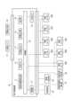
安全監視装置の構成例を図1に示す。なお、以下の説明では、安全監視装置が車載器により構成される場合を例に説明する。
図1に示した安全監視装置は、車載器の本体として車両に搭載される電子制御装置10を備えている。また、この電子制御装置10に記録カード21、警報出力部22、車両電源23、車速検出部24、4つの荷重センサ25A~25D、3つの傾斜センサ26A~26C、操舵角速度検出部27、および車両位置検出部28が接続されている。<Example of configuration of safety monitoring device>
Figure 1 shows an example of the configuration of a safety monitoring device. In addition, in the following description, a case where the safety monitoring device is configured by an on-vehicle device will be explained as an example.
The safety monitoring device shown in FIG. 1 includes an
また、電子制御装置10は、旋回加速度検出部11、本体メモリ12、外部出力I/F(インタフェース)13、警報出力部14、表示部15、制御部16、電源部17、および入出力I/F18を備えている。 The
記録カード21は、電子制御装置10に対して着脱自在な不揮発性のメモリカードであり、運転者毎に個別に用意される。この記録カード21は、荷物の輸送品質に関連する情報を含む運行記録情報を記録するために利用できる。 The recording card 21 is a nonvolatile memory card that is removably attached to the
警報出力部22は、制御部16が後述する運転手の安全評価を行うための動作を実行し、安全運転から逸脱したと判断した場合に、その旨を表す警報を、表示、警報音、文字情報などの形態で自車両の運転手や管理者などに報知するために利用される。また、荷物の異常に関連する警報を報知するためにも利用される。
車両電源23は、車両に搭載されているバッテリーなどの電源であり、電子制御装置10等の車載器に対して所定の直流電力を供給することができる。When the
The
車速検出部24は、変速機の出力軸、あるいは各車輪の回転に連動して発生する車速パルス信号を生成する。電子制御装置10は、車速検出部24が出力する車速パルス信号に基づいて、各時点の車速(km/h)を算出できる。なお、電子制御装置10が車速パルス信号以外の情報に基づいて車速を把握することも可能である。例えば、GPS(Global Positioning System)受信機を搭載する場合には、この受信信号から車速の情報を算出できる。 The vehicle
荷重センサ25A、25B、25C、および25Dは、それぞれ、前方左側(FL)、前方右側(FR)、後方左側(RL)、および後方右側(RR)の各位置の車輪を支持するサスペンションに加わる荷重の大きさを計測できるように設置されている。
傾斜センサ26Aは、前方左側の車輪回転軸と、前方右側の車輪回転軸との間を結ぶ軸(前輪側車軸)の水平方向に対する傾斜角度の大きさを検出できる位置に設置されている。また、傾斜センサ26Bは、後方左側の車輪回転軸と、後方右側の車輪回転軸との間を結ぶ軸(後輪側車軸)の水平方向に対する傾斜角度の大きさを検出できる位置に設置されている。また、傾斜センサ26Cは、前輪側車軸と後輪側車軸とを結ぶ軸(前後方向車軸)の水平方向に対する傾斜角度の大きさを検出できる位置に設置されている。 The
操舵角速度検出部27は、ステアリングシャフトの近傍に取り付けられた図示しない操舵角センサから単位時間ごとにステアリングシャフトの回転角を示す信号を取得し、操舵角速度を算出する。制御部16は、操舵角速度検出部27から操舵角速度を表す信号を取得する。
車両位置検出部28は、図示しないGPS受信機により構成されており、現在位置情報を生成する。GPS受信機は複数のGPS(Global Positioning System)衛星からの電波を受信して、受信地点である車両の現在位置を算出できる。The steering angular
The vehicle
旋回加速度検出部11は、自車両の旋回時に荷物等に加わる水平面内の加速度の方向および大きさを表す電気信号を出力できる。
本体メモリ12は、事前に定めた各種定数データや電子制御装置10の動作に必要なプログラムが書き込まれた不揮発性メモリ(EEPROMなど)と、一時データを保持するためのメモリ(RAM)とを備えている。The turning
The
外部出力I/F13は、制御部16が記録カード21のデータにアクセスするための信号処理と、警報出力部22への信号出力のための制御を実施する。
警報出力部14は、電子制御装置10に内蔵された警報ランプやブザーなどを用いて安全運転から逸脱したと判断した場合や異常の発生を運転手に報知するために利用される。The external output I/
The
表示部15は、自車両の運転手の位置から視認が容易な状態で配置された平面ディスプレイを備えている。この平面ディスプレイの二次元画面に、カラー画像や文字情報などを必要に応じて表示できる。 The
制御部16は、マイクロコンピュータを主体とする電子回路により構成され、事前に用意されたプログラムを実行することにより、電子制御装置10に必要とされる各種の制御機能を実現する。 The
電源部17は、車両電源23から供給される電力に基づいて、安定した直流電力を生成し、この直流電力は電子制御装置10内部の各回路と、荷重センサ25A~25Dおよび傾斜センサ26A~26Cへ電源として供給する。
入出力I/F18は、車速検出部24、荷重センサ25A~25D、傾斜センサ26A~26C、操舵角速度検出部27、車両位置検出部28等の各信号を制御部16に入力するための信号処理を実施する。The
The input/output I/F 18 performs signal processing for inputting signals from the vehicle
<荷重センサの構成例>
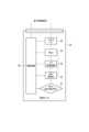
荷重センサ25の構成例を図2に示す。図1中に示した荷重センサ25A~25Dのそれぞれが図2の荷重センサ25に相当する。<Example of configuration of load sensor>
An example of the configuration of the
図2に示すように、この荷重センサ25は歪み検出素子31、専用IC(ASIC)32、V/F変換回路33、MCU(マイクロコントローラ)34、入出力I/F35、および電源回路36を内蔵している。 As shown in FIG. 2, this
歪み検出素子31は、これが設置されている箇所に加わる荷重により生じる歪み量を検出する。専用IC32は、歪み検出素子31が検出した歪み量、すなわち荷重に相当する電圧(V)の電気信号を生成する。V/F変換回路33は、専用IC32が出力する信号の電圧変化を周波数(F)の変化に変換する。具体的には、V/F変換回路33が出力するパルス信号の周波数が、歪み検出素子31に加わった荷重に相当する。 The
MCU34は、V/F変換回路33が出力するパルス信号の周波数に基づいて、検出された荷重の大きさを表すデータを生成する。MCU34が生成した荷重の検出データは、入出力I/F35を経由して電子制御装置10に入力される。 The
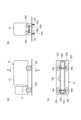
<監視対象のトラック車両の構成例>
監視対象のトラック車両41の構成例を図3(a)~図3(c)に示す。図3(a)、図3(b)、および図3(c)は、それぞれトラック車両41の正面図、右側面図、および底面図である。<Example of configuration of monitored truck vehicle>
Examples of the configuration of the
図3(a)に示した例では、トラック車両41の運転席の近傍に電子制御装置10が設置されている。電子制御装置10に接続された4つの荷重センサ25A、25B、25C、および25Dは、それぞれ、左前方の車輪44A、右前方の車輪44B、左後方の車輪44C、および右後方の車輪44Dの近傍に設置されている。 In the example shown in FIG. 3(a), the
また、傾斜センサ26Aは前方側の車軸43A近傍に設置され、傾斜センサ26Bは後方側の車軸43B近傍に設置されている。傾斜センサ26Cは、車軸43A、43Bの中間位置に設置されている。つまり、傾斜センサ26Aは横方向の前方車軸43Aの傾斜角度を検出し、傾斜センサ26Bは横方向の後方車軸43Bの傾斜角度を検出し、傾斜センサ26Cは前後方向の車軸の傾斜角度を検出する。 Further, the
トラック車両41の荷台42の内部空間には、様々な荷物が積載される。荷物の積載状況に応じて、各位置の荷重W1、W2等が変動する。また、各位置の荷重W1、W2のバランスに応じて、車軸43Aの傾斜角度、車軸43Bの傾斜角度、および前後方向の車軸の傾斜角度が変動する。 Various cargoes are loaded into the interior space of the
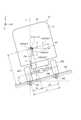
<車体と重心位置との関係>
トラック車両41を後方から視た場合の車体と重心位置との関係の例を図4に示す。
なお、図4において、x軸がトラック車両41の車幅方向、z軸がその高さ方向をそれぞれ示している。y軸は前後方向を表している。そして、x軸をトラック車両41の前方側及び後方側の各々の車軸43A、43Bと設定したときに、x軸とz軸とを通るようにトラック車両41の断面Pを設定している。これは、トラック車両41の前方側及び後方側の車軸43A、43Bの各々は傾斜角θが異なるためである。<Relationship between vehicle body and center of gravity position>
FIG. 4 shows an example of the relationship between the vehicle body and the position of the center of gravity when the
In FIG. 4, the x-axis indicates the width direction of the
トラック車両41は、半径rの一対の車輪(タイヤ)44A-44B間を車輪距離bとして表してある。そして、車両重量m(荷物等を含む)はトラック車両41の重量を示している。
各断面Pの重心位置Cは、トラック車両41に加わる荷重に応じて変化する前記車両の重心の断面Pにおける位置を示し、二次元の重心座標(x1,z1)で示すことができる。そして、重心位置Cは、荷物等を積載していない空荷状態が初期位置となり、荷物等が積載されて重量が増加することで、重心は高さ方向の上方に向かって重量の増加量に応じた分だけ移動することになる。重心高さhは、地面100から重心位置Cまでの高さを示している。The
The center of gravity position C of each cross section P indicates the position of the center of gravity of the vehicle in the cross section P that changes depending on the load applied to the
重力加速度gは、トラック車両41に働く重力をそのトラック車両41の質量で割った値を示している。遠心加速度aは、トラック車両41が左折や右折に応じて生じるみかけ上の力を示している。傾斜角θは、トラック車両41が所望の方向(図4では左方向)に傾斜したときの角度を示し、本実施形態では左側の車輪の中心線が地面100と交わった支点Aの傾斜角を示している。そして、トラック車両41の右側の車輪の中心線と地面100と交わった点を支点Bとしている。 The gravitational acceleration g indicates a value obtained by dividing the gravity acting on the
車幅bのトラック車両41が図3(b)に示すように水平面上にある場合、左側の車輪44A、44Cに重力W1、右側の車輪44B、44Dに重力W2がそれぞれ加わり、且つ、トラック車両41が図4に示すように傾斜角θの傾斜面上にある場合、左側の車輪44A、44Cに重量W1’、右側の車輪44B、44Dに重量W2’がそれぞれ加わっていることを荷重検出部が検出した場合、前方側及び後方側の各重心位置Cの二次元重心座標(x1,z1)は以下の式1、式2で算出することができる。
x1=(W2/(W1+W2))×b ・・・(式1)
z1=(x1-(W2’/(W1+W2)×b))/tanθ ・・・(式2)When a
x1=(W2/(W1+W2))×b...(Formula 1)
z1=(x1-(W2'/(W1+W2)×b))/tanθ...(Formula 2)
図4において、横転限界線Lが、トラック車両41の横転する基準線となっており、重心座標(x1,z1)が横転限界線Lを左側へ超えると横転することになる。すなわち、横転限界線Lの右側が安全走行可能な領域となる。これは、支点Bに対しても同様に設定されるものである。 In FIG. 4, the rollover limit line L is a reference line for the
このような場合に、支点Aを中心にトラック車両41を左側に傾斜角θだけ傾けると、重心位置Cから地面100に対する垂線によって車輪距離bは第1距離b1と第2距離b2(b-b1)とに分割される。そして、モーメントのつり合いより、以下の式3の条件を満たした場合に自重により左に横転することになる。すなわち、式3の左辺が車軸43A、43Bに平行な力によるモーメントを示し、右辺が車軸43A、43Bに垂直な力によるモーメントを示している。
((mg・sinθ)+(-ma・cosθ))h > ((mg・cosθ)+(ma・sinθ))b1
・・・(式3)In such a case, when the
((mg・sinθ)+(−ma・cosθ))h > ((mg・cosθ)+(ma・sinθ))b1
...(Formula 3)
また、図1に示した安全監視装置においては、傾斜センサ26Cが前後方向の車軸の傾斜角度を検出するので、図4の場合と同様に前後方向の車軸の傾斜角度を考慮して、前後方向(y軸方向)の重心位置も算出できる。つまり、重心位置Cの三次元座標(x,y,z)を特定できる。 In addition, in the safety monitoring device shown in FIG. 1, since the
<安全評価動作の説明>
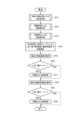
安全監視装置における安全評価動作を図5に示す。すなわち、トラック車両41における運転手の安全評価を行うための動作を電子制御装置10の制御部16が実行する。<Explanation of safety evaluation operation>
Figure 5 shows the safety evaluation operation in the safety monitoring device. That is, the
制御部16は、時刻及び車両位置による注意度判定値をS11で設定する。時刻及び車両位置による注意度判定値の具体的な設定手順は、後述するように、図6に示す判定値設定動作に従って行われる。 The
次に、制御部16は、積載重量による危険度判定値をS12で設定する。積載重量による危険度判定値の具体的な設定手順は、後述するように、図7に示す判定値設定動作に従って行われる。次に、制御部16は、車両重心による危険度判定値をS13で設定する。車両重心による危険度判定値の具体的な設定手順は、後述するように、図8に示す判定値設定動作に従って行われる。 Next, the
そして、制御部16は、S11~S13で設定された判定値を、後述する設定テーブル(図12)に適用して、現在のトラック車両41の走行状態に対して安全評価を行うためのしきい値(規定値)を設定する(S14)。なお、本実施形態では、車速及び操舵角速度に対するしきい値が設定される場合を例に説明する。 Then, the
次に、制御部16は、車速検出部24からの車速パルス信号に基づいて、現在のトラック車両41の車速(km/h)を算出する(S15)。そして、現在の車速がS14で設定された車速のしきい値を超えているかを識別し(S16)、超えているならば安全運転から逸脱したと判断したことを表す警報を、表示、警報音、文字情報などの形態で警報出力部22に報知させる(S17)。また、車速がしきい値を超えたことを示すイベントを運行データとして記録する。一方、現在の車速がS14で設定された車速のしきい値を超えていないならばS18に進む。 Next, the
制御部16は、操舵角速度検出部27から現在の操舵角速度を表す信号を取得する(S18)。そして、現在の操舵角速度がS14で設定された操舵角速度のしきい値を超えているかを識別し(S19)、超えているならば安全運転から逸脱したと判断したことを表す警報を、表示、警報音、文字情報などの形態で警報出力部22に報知させる(S20)。また、操舵角速度がしきい値を超えたことを示すイベントを運行データとして記録する。一方、現在の車速がS14で設定された操舵角速度のしきい値を超えていないならば処理を終了する。制御部16は、トラック車両41の運行中に、この安全評価動作を所定の時間間隔で繰り返し実行する。 The
<時刻及び車両位置に基づく判定値設定動作>
制御部16は、上記安全評価動作のS11における時刻及び車両位置による注意度判定を、図6に示す判定値設定動作に従って実行する。<Judgment value setting operation based on time and vehicle position>
The
制御部16は、まずS31で注意度判定値を初期値として0に設定するとともに、S32で現在時刻を取得する。現在時刻は、電子制御装置10の内部時計あるいはGPS受信機により受信したGPS衛星からの電波によって求められる。 The
制御部16は、取得した現在時刻が注意時間帯に含まれているかをS33で識別する。注意時間帯は予め設定されており、例えば通勤・通学時間帯、夕方や夜間の時間帯が含まれる。この注意時間帯は、例えばトラック車両41の運行管理を行う企業ごとや、その企業の事業所ごとに設定することができる。制御部16は、現在時刻が注意時間帯に含まれているならばS34に進み、含まれていないならばS31に戻る。 The
制御部16は、車両位置検出部28から現在位置情報をS34で取得すると、トラック車両41が注意エリアを走行中であるかを識別する(S35)。注意エリアは予め設定されており、例えば通学路や事故多発地帯、急カーブが連続する地点などが含まれている。この注意エリアも企業ごとや事業所ごとなどによって自由に設定される。制御部16は、トラック車両41が注意エリアを走行中と識別したならばS36に進み注意度判定値を1に設定し処理を終了する。一方、制御部16は、トラック車両41が注意エリア外であると識別したならば、注意度判定値が0に設定されたままの状態で処理を終了する。
なお、図6に従った上記の注意度判定値設定動作は一例であり、例えば注意時間帯又は注意エリアのいずれか一方が該当していれば注意度判定値を1に設定してもよい。また、注意時間帯及び注意エリアの双方に該当している場合には注意度判定値を2に設定するようにしてもよい。When the
Note that the above caution level determination value setting operation according to FIG. 6 is just an example, and for example, if either the caution time period or the caution area is applicable, the caution level determination value may be set to 1. Furthermore, if the situation falls under both the caution period and the caution area, the caution level determination value may be set to 2.
<積載重量に基づく判定値設定動作>
制御部16は、上記安全評価動作のS12における積載重量による危険度判定を、図7に示す判定値設定動作に従って実行する。すなわち、制御部16は、トラック車両41の積載重量に応じた危険度の判定値を設定する。<Judgment value setting operation based on loaded weight>
The
制御部16は、まずS41で荷重センサ25A~25Dから入力される信号に基づき、トラック車両41に積載されている荷物の積載重量を算出する。すなわち、制御部16は、荷物等を積載していない空荷状態において予め記憶されている荷重センサ25A~25Dの値と、これらの荷重センサ25A~25Dから現在入力される値を比較することにより積載重量を算出する。 First, in S41, the
制御部16は、S42に進むと、積載重量が5t以上であるか否かを識別する。5t未満と識別した場合には、積載重量による危険度の判定値を1に設定し(S43)、処理を終了する。制御部16は、積載重量が5t以上と識別するとS44に進み、積載重量が10t以上であるか識別する。10t未満と識別した場合には、積載重量による危険度の判定値を2に設定し(S45)、10t以上と識別した場合には、積載重量による危険度の判定値を3に設定する(S46)。 Proceeding to S42, the
<車両重心に基づく判定値設定動作>
制御部16は、上記安全評価動作のS13における車両重心による危険度判定を、図8に示す判定値設定動作に従って実行する。すなわち、制御部16は、トラック車両41の車両重心に応じた危険度の判定値を設定する。<Judgment value setting operation based on vehicle center of gravity>
The
制御部16は、トラック車両41の車両重心位置を算出する(S51)。車両重心位置は、例えば図9に示す重心位置算出動作に従って算出される。この重心位置算出動作は、トラック車両41への荷積み作業が完了し運行が開始されると、電子制御装置10の制御部16によって繰り返し実行される。 The
制御部16は、例えば車速検出部24が出力する信号に基づいて現在のトラック車両41の走行速度(車速:km/h)をS61で検出し、検出した車速を事前に定めた車速閾値とS62で比較することにより、自車両が停車状態か否かを識別する。停車状態を検知すると、S63以降の処理に進む。 For example, the
つまり、制御部16は、トラック車両41の走行に起因して発生する振動や加速度の影響を受けない状態で、S63以降の処理に進み正しい重心位置を算出することができる。なお、「停車状態」以外の条件をS62の処理に更に追加しても良い。例えば、停車状態で且つ路面がほぼ水平状態である場合にS63に進むようにすれば、計算誤差の発生をさらに抑制できる。 In other words, the
制御部16は、S63で荷重センサ25A~25Dの出力をそれぞれ読み取って各車輪位置の荷重を計測する。
制御部16は、S64で傾斜センサ26A、26Bの出力をそれぞれ読み取って前後の各車軸43A、43Bの傾斜角度θを計測する。In S63, the
In S64, the
制御部16は、前記式1、式2と、S63、S64で得られた荷重および傾斜角度の計測値を利用して、S65で重心位置Cの二次元座標(x,z)を車軸毎に算出する。
制御部16は、S66で傾斜センサ26Cの出力を読み取って前後方向の車軸における傾斜角度θを計測する。そして、S63、S66で得られた荷重および傾斜角度の計測値を利用して、S67で重心位置Cの前後方向の二次元座標(y,z)を算出する。In S65, the
In S66, the
制御部16は、S65で得られた車軸毎の重心位置の二次元座標(x,z)と、S67で得られた前後方向の重心位置の二次元座標(y,z)とを合成することにより、重心位置Cの三次元座標(x,y,z)を算出する(S68)。 The
制御部16は、S68で算出した最新の重心位置Cの三次元座標(x,y,z)のデータに基づいて、S69で重心位置Cのブロック割り当てを実行する。重心位置のブロック割り当ては、例えば図10に示すように行われる。
図10は、トラック車両41の三次元形状を、トラック車両41の後方斜め右上から見下ろした状態を模擬している。The
FIG. 10 simulates the three-dimensional shape of the
図10の例では、立体的な多数のブロックにより区画されており、x軸方向に4個、y軸方向に4個、z軸方向に4個、すなわち合計で64個のブロックにより構成されている。これら64個のブロックそれぞれには、3次元のアドレスが割り当てられている。このアドレスは、x軸方向にはトラック車両41の左側から右側へ1,2,3,4の数字がそれぞれ割り当てられ、y軸方向にはトラック車両41の後方から前方へA,B,C,Dがそれぞれ割り当てられ、z軸方向にはトラック車両41の下方から前方へa,b,c,dがそれぞれ割り当てられている。したがって、制御部16は、S68で算出した重心位置Cの3次元座標(x,y,z)が、いずれのブロックの領域に該当するかを識別し、そのブロックのアドレスを取得する。本実施形態においては、ブロックのx軸方向のアドレス(1~4)及びz軸方向のアドレス(a~d)の2つを用いる場合を例示している。以上により、図8に示す判定値設定動作のS51における車両重心位置の算出が完了する。 In the example of FIG. 10, the area is partitioned into a large number of three-dimensional blocks, and consists of 4 blocks in the x-axis direction, 4 blocks in the y-axis direction, and 4 blocks in the z-axis direction, that is, 64 blocks in total. There is. A three-dimensional address is assigned to each of these 64 blocks. These addresses are assigned
次に、制御部16は、S52に進み車両重心位置に対応した危険度判定値を設定する。トラック車両41の重心位置に応じた判定値の設定は、図11に示す判定値テーブルを用いて行われる。
判定値テーブルは、各ブロックに対し、最も安全性が高い危険度1から、最も危険性が高い危険度5までのいずれかの危険度を割り当てている。例えば、x軸方向においては、トラック車両41の側面寄りとなるアドレス1又は4のブロックの危険度が、トラック車両41の中央寄りとなるアドレス2又は3のブロックの危険度よりも高く設定されている。また、z軸方向においては、トラック車両41の上方寄りとなるアドレスdのブロックの危険度が最も高く設定されており、アドレスがc、b、aとなるにつれて危険度が低くなるように設定されている。一例として、x軸方向とz軸方向のアドレスが1又は4とdの組み合わせとなるブロックには、危険度として最も高い5が割り当てられ、2又は3とaの組み合わせとなるブロックには、危険度として最も低い1が割り当てられている。Next, the
The determination value table assigns each block a risk level from
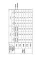
図12は、現在のトラック車両41の走行状態に対して安全評価を行うためのしきい値を設定する設定テーブルである。制御部16は、上記のように時刻・車両位置による注意度判定値、積載重量による危険度判定値、車両重心による危険度判定値をそれぞれ設定すると、図12に示す設定テーブルを参照して、車速及び操舵角速度に対するしきい値を設定する。 FIG. 12 is a setting table for setting a threshold value for performing a safety evaluation on the current running state of the
このように安全評価を行うためのしきい値が設定されると、制御部16は、上記安全評価動作のS16やS19のように、現在の車速や操舵角速度と、設定テーブルにより設定されているしきい値とを比較し、しきい値を超えているならば安全運転から逸脱したと判断したことを表す警報を、表示、警報音、文字情報などの形態で警報出力部22に報知させ、車速あるいは操舵角速度がしきい値を超えたことを示すイベントを運行データとして記録する。そして、制御部16は、トラック車両41の走行中に所定の時間間隔で安全評価動作を繰り返しており、1回の動作ごとにS11~S13において、時刻・車両位置による注意度判定値、積載重量による危険度判定値、車両重心による危険度判定値を新たに取得し、S14においてしきい値を最新の値に更新するので、実際の走行状況に応じた精度の高い安全評価を実施することができる。 When the threshold value for performing safety evaluation is set in this way, the
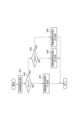
<車載器を含む通信システムの構成例>
車載器を含む通信システムの構成例を図13に示す。
図13に示した通信システムにおいては、車載器としてトラック車両41に搭載された電子制御装置10に、無線通信モジュール51が接続されている状況を想定している。したがって、図13に示した電子制御装置10は車両外部の装置との間で無線通信することができる。<Example of configuration of communication system including onboard equipment>
FIG. 13 shows an example of the configuration of a communication system including an on-vehicle device.
In the communication system shown in FIG. 13, it is assumed that a
図13の例では、データセンタ52および事務所PC53がインターネット54を介して互いに接続されている。また、無線基地局55がインターネット54に接続されている。トラック車両41上の無線通信モジュール51は、無線基地局55を介してデータセンタ52内のサーバとの間で、または事務所PC53との間で通信することができる。 In the example of FIG. 13, a
したがって、図13に示した通信システムにおいては、トラック車両41における安全運転評価を、電子制御装置10、データセンタ52、事務所PC53のいずれでも行うことができる。すなわち、図5~図9に示した各処理に相当する機能は、電子制御装置10、データセンタ52、事務所PC53のいずれでも行うことができる。 Therefore, in the communication system shown in FIG. 13, safe driving evaluation of the
なお、事務所PC53は、トラック車両41の運行を管理する企業等の事務所内に設置され、トラック車両41の運行管理や各運転手の労務管理、安全管理などの用途で使用される。 Note that the
事務所PC53は、例えば電子制御装置10から取り外した記録カード21から、または無線通信により無線基地局55、データセンタ52を経由して電子制御装置10から運行情報のデータを取り込む。そして、事務所PC53は運行中に計測された重心位置Cの三次元座標を含む運行情報を、電子データとして保存したり、紙の媒体に印刷して出力することができる。また、荷主などの顧客に対して、輸送品質の証拠文書として、電子制御装置10が記録カード21に記録した重心位置Cの三次元座標のデータを提出することも可能である。 The
企業等の管理者は、事務所PC53により運転手毎に積載した荷物に応じた適切な運転を行っているか把握できるので、各運転手の運転状態を公正に評価することが容易になる。また、事務所PC53は、この評価結果を日報として出力してもよい。 Since the manager of a company or the like can use the
<安全監視装置および安全監視方法の利点>
例えば図1に示した電子制御装置10が図5~図9に示した処理を実行する場合には、現在の積荷の状態を運転評価のしきい値(規定値)に反映させることができるので、高精度な安全評価が可能になる。すなわち、車両が走行を開始した後で、自動計測部が積載状況を計測し荷物監視情報を生成し、この荷物監視情報に基づいて運転評価を実行するので、積荷の状態に応じた適正な安全運転が実行されているかを監視することが可能となる。また、車両の安定走行のために、積荷の状態に応じて運転の際に最も注意すべき車速と操舵角速度に対する評価を適切に行うことにより、運転操作に対する評価の信頼性を高めることができる。<Advantages of safety monitoring devices and safety monitoring methods>
For example, when the
また、車両の走行開始後に停止した際に荷物監視情報を生成する場合には、車両走行に起因する振動や加速度の影響を受けない状態で荷物監視情報を取得できるので、現在の積荷の状態に応じた適切な評価用のしきい値を設定でき、このしきい値を用いて精度の高い安全運転評価を実行することができる。また、積荷の積載状況のうち、車両の走行状態に最も影響を与える積荷の重さおよび車両の重心位置を安全運転評価に反映することができる。
そのため、荷物の輸送品質を改善するための運転手の教育と、そのための公正な評価のために利用できる。また、評価の結果を事務所PCに入力し、事務所PCにおいて日報を作成することもできる。あるいは事務所PCの代わりにデータセンタが必要なデータを取得し、安全評価あるいは日報の作成を代行してもよい。In addition, when generating cargo monitoring information when the vehicle stops after starting running, the cargo monitoring information can be obtained without being affected by vibrations or acceleration caused by the vehicle running, so the current cargo status can be An appropriate threshold value for evaluation can be set according to the situation, and a highly accurate safe driving evaluation can be performed using this threshold value. Moreover, among the loading conditions of the cargo, the weight of the cargo and the position of the center of gravity of the vehicle, which have the greatest influence on the running state of the vehicle, can be reflected in the safe driving evaluation.
Therefore, it can be used for driver education and fair evaluation to improve the quality of cargo transportation. It is also possible to input the evaluation results into the office PC and create a daily report on the office PC. Alternatively, instead of the office PC, a data center may acquire the necessary data and perform safety evaluations or create daily reports.
なお、制御部16は、図10に示したトラック車両41の車体形状を模擬した三次元画像を立体的に画面に表示し、算出した最新の重心位置Cの三次元座標(x,y,z)の位置が運転手により視覚的に特定できるように色の違いや濃淡を用いて表現するようにしてもよい。これにより、運転者は、例えば重心位置Cがトラック車両41の側面寄りであったり上方寄りであることを画像により視認すると、慎重な運転を心掛けるようになるので、設定テーブルにより車速や操舵角速度に対し厳しいしきい値が設定されたとしても、安全運転から逸脱した旨を表す警報が発せられる前に事前にしきい値以下となる運転を実施することが可能になる。また、音声出力機能を搭載している場合には、重心位置Cの三次元座標を音声により出力してもよい。また、無線通信機能を搭載している場合には、重心位置Cの三次元座標のデータを、事前に定めた送信先に向けて送信してもよい。 The
また、制御部16は、トラック車両41への荷積み作業が完了し、走行を開始する前の時点で、予め重心位置Cの三次元座標(x,y,z)を算出し、保存するようにしてもよい。この場合、制御部16は、走行開始前と走行開始後における重心位置Cの変化量を安全運転評価の判断基準に加えるようにしてもよい。また、重心位置Cの変化量が所定値を超えた場合には、運転手に対し警報出力部22を用いて警告するようにしてもよい。 Further, the
ここで、上述した本発明の実施形態に係る安全監視装置および安全監視方法の特徴をそれぞれ以下[1]~[5]に簡潔に纏めて列記する。
[1] 車両(トラック車両41)の走行状態を検知する走行状態検知部(制御部16、S15、S18)と、
少なくとも前記車両の走行開始後に荷物の積載状況を計測し、当該積載状況を反映した荷物監視情報を生成する自動計測部(制御部16、S63~S69)と、
前記走行状態を規定値と比較することにより運転評価を実行する運転評価部(制御部16、S16、S19)と、を備え、
前記運転評価部は、前記荷物監視情報に基づいて前記規定値を設定する(制御部16、S14)、
ことを特徴とする安全監視装置(電子制御装置10)。Here, the features of the safety monitoring device and the safety monitoring method according to the embodiments of the present invention described above are briefly summarized and listed below in [1] to [5].
[1] A running state detection unit (control
an automatic measurement unit (control
A driving evaluation unit (control
The driving evaluation unit sets the specified value based on the baggage monitoring information (control
A safety monitoring device (electronic control device 10) characterized by:
[2] 前記走行状態検知部は、前記走行状態として、前記車両の車速および操舵角速度の少なくともいずれか一方を検知する、
ことを特徴とする上記[1]に記載の安全監視装置。[2] The running state detection unit detects at least one of a vehicle speed and a steering angular velocity of the vehicle as the running state.
The safety monitoring device according to item [1] above.
[3] 前記車両の停車状態を検知する停車検知部(制御部16、S61~S62)を更に備え、
前記自動計測部は、前記車両が走行を開始した後で、前記停車状態の検知に基づいて、前記積載状況を計測し前記荷物監視情報を生成する、
ことを特徴とする上記[1]又は[2]に記載の安全監視装置。[3] Further comprising a stop detection unit (control
The automatic measurement unit measures the loading status and generates the luggage monitoring information based on the detection of the stopped state after the vehicle starts traveling.
The safety monitoring device according to [1] or [2] above, characterized in that:
[4] 前記荷物監視情報は、前記荷物の重量および前記車両の重心位置に関する情報を含む、
ことを特徴とする上記[1]乃至[3]のいずれかに記載の安全監視装置。[4] The luggage monitoring information includes information regarding the weight of the luggage and the position of the center of gravity of the vehicle,
The safety monitoring device according to any one of [1] to [3] above.
[5] 車両の走行状態を検知し(S15、S18)、
少なくとも前記車両の走行開始後に荷物の積載状況を反映した荷物監視情報の生成を繰り返し実行し(S63~S69)、
前記走行状態を、前記荷物監視情報に基づいて設定された規定値と比較することにより運転評価を実行する(S14、S16、S19)、
ことを特徴とする安全監視方法。[5] Detect the running state of the vehicle (S15, S18),
At least after the vehicle starts traveling, repeatedly generates baggage monitoring information that reflects the loading status of the baggage (S63 to S69);
Performing a driving evaluation by comparing the driving state with a specified value set based on the baggage monitoring information (S14, S16, S19);
A safety monitoring method characterized by:
10 電子制御装置
11 旋回加速度検出部
12 本体メモリ
13 外部出力I/F
14 警報出力部
15 表示部
16 制御部
17 電源部
18 入出力I/F
21 記録カード
22 警報出力部
23 車両電源
24 車速検出部
25,25A,25B,25C,25D 荷重センサ
26A,26B,26C 傾斜センサ
27 操舵角速度検出部
28 車両位置検出部
31 歪み検出素子
32 専用IC
33 V/F変換回路
34 MCU
35 入出力I/F
36 電源回路
41 トラック車両
42 荷台
43A,43B 車軸
44A,44B,44C,44D 車輪
51 無線通信モジュール
52 データセンタ
53 事務所PC
54 インターネット
55 無線基地局10
14
21
33 V/
35 Input/output I/F
36
54
Claims (5)
Translated fromJapanese少なくとも前記車両の走行開始後に荷物の積載状況を計測し、当該積載状況を反映した荷物監視情報を生成する自動計測部と、
前記走行状態を規定値と比較することにより運転評価を実行する運転評価部と、を備え、
前記運転評価部は、前記荷物監視情報に基づいて前記車両の操舵角速度の前記規定値を設定し、
前記走行状態検知部は、前記走行状態として、前記車両の操舵角速度を検知し、
前記運転評価部は、前記検知された操舵角速度を前記操舵角速度の前記規定値と比較することにより運転評価を実行する、
ことを特徴とする安全監視装置。a driving state detection unit that detects the driving state of the vehicle;
an automatic measurement unit that measures the loading status of luggage at least after the vehicle starts traveling, and generates luggage monitoring information that reflects the loading status;
a driving evaluation unit that performs driving evaluation by comparing the driving state with a specified value,
The driving evaluation unit sets the specified valueof the steering angular velocity of the vehicle based on the luggage monitoring information,
The running state detection unitdetects a steering angular velocity of the vehicle as the running state,
The driving evaluation unit executes driving evaluation by comparing the detected steering angular velocity with the specified value of the steering angular velocity.
A safety monitoring device characterized by:
ことを特徴とする請求項1に記載の安全監視装置。The driving state detection unit detects a vehicle speed of the vehicle as the driving state.
The safety monitoring device according to claim 1, characterized in that:
前記自動計測部は、前記車両が走行を開始した後で、前記停車状態の検知に基づいて、前記積載状況を計測し前記荷物監視情報を生成する、
ことを特徴とする請求項1又は2に記載の安全監視装置。Further comprising a stop detection unit that detects a stop state of the vehicle,
The automatic measurement unit measures the loading status and generates the luggage monitoring information based on the detection of the stopped state after the vehicle starts traveling.
The safety monitoring device according to claim 1 or 2, characterized in that:
ことを特徴とする請求項1乃至3のいずれか1項に記載の安全監視装置。The luggage monitoring information includes information on the weight of the luggage and the position of the center of gravity of the vehicle in the vertical direction and the horizontal direction.
The safety monitoring deviceaccording to any one of claims 1 to 3, characterized in that:
少なくとも前記車両の走行開始後に荷物の積載状況を反映した荷物監視情報の生成を繰り返し実行し、
前記走行状態を、前記荷物監視情報に基づいて設定された規定値と比較することにより運転評価を実行し、
前記走行状態として、前記車両の操舵角速度を検知し、
前記検知された操舵角速度を前記車両の操舵角速度の前記規定値と比較することにより運転評価を実行する、
ことを特徴とする安全監視方法。Detects the driving condition of the vehicle,
Repeatedly generating luggage monitoring information that reflects the loading status of luggage at least after the vehicle starts traveling;
Performing a driving evaluation by comparing the driving state with a specified value set based on the baggage monitoring information;
detecting a steering angular velocity of the vehicle as the running state;
performing a driving evaluation by comparing the detected steering angular velocity with the specified value of the steering angular velocity of the vehicle;
A safety monitoring method characterized by:
Priority Applications (1)
| Application Number | Priority Date | Filing Date | Title |
|---|---|---|---|
| JP2019026529AJP7359549B2 (en) | 2019-02-18 | 2019-02-18 | Safety monitoring device and safety monitoring method |
Applications Claiming Priority (1)
| Application Number | Priority Date | Filing Date | Title |
|---|---|---|---|
| JP2019026529AJP7359549B2 (en) | 2019-02-18 | 2019-02-18 | Safety monitoring device and safety monitoring method |
Publications (2)
| Publication Number | Publication Date |
|---|---|
| JP2020131865A JP2020131865A (en) | 2020-08-31 |
| JP7359549B2true JP7359549B2 (en) | 2023-10-11 |
Family
ID=72262018
Family Applications (1)
| Application Number | Title | Priority Date | Filing Date |
|---|---|---|---|
| JP2019026529AActiveJP7359549B2 (en) | 2019-02-18 | 2019-02-18 | Safety monitoring device and safety monitoring method |
Country Status (1)
| Country | Link |
|---|---|
| JP (1) | JP7359549B2 (en) |
Families Citing this family (4)
| Publication number | Priority date | Publication date | Assignee | Title |
|---|---|---|---|---|
| JP7635818B2 (en)* | 2021-02-18 | 2025-02-26 | 日本電気株式会社 | Improvement item detection device, improvement item detection method, and program |
| KR20230169314A (en)* | 2021-05-14 | 2023-12-15 | 가부시키가이샤 아이에이치아이 | Method and device for detecting vehicle loading abnormalities |
| CN115965604B (en)* | 2022-12-30 | 2023-07-07 | 平湖市凯鑫塑业股份有限公司 | Case and bag safety monitoring method and system based on case and bag fittings |
| CN118189882B (en)* | 2024-05-14 | 2024-08-27 | 北京易控智驾科技有限公司 | A method and device for detecting the angle of cargo box of an unmanned vehicle |
Citations (7)
| Publication number | Priority date | Publication date | Assignee | Title |
|---|---|---|---|---|
| JP2004209998A (en) | 2002-12-26 | 2004-07-29 | Mitsubishi Fuso Truck & Bus Corp | Integrated control device of vehicle |
| JP2009156746A (en) | 2007-12-27 | 2009-07-16 | Isuzu Motors Ltd | Load center-of-gravity height estimation device of vehicle |
| JP2012171430A (en) | 2011-02-18 | 2012-09-10 | Advics Co Ltd | One-sided load determination apparatus |
| JP2012224270A (en) | 2011-04-21 | 2012-11-15 | Yazaki Corp | Cargo collapse prediction device |
| JP2014000896A (en) | 2012-06-19 | 2014-01-09 | Hino Motors Ltd | Centroid position estimation device, vehicle, centroid position estimation method, and program |
| JP2015169453A (en) | 2014-03-05 | 2015-09-28 | 国立大学法人東京海洋大学 | Rollover warning device |
| JP2017033080A (en) | 2015-07-29 | 2017-02-09 | いすゞ自動車株式会社 | Direction indicator control device |
Family Cites Families (1)
| Publication number | Priority date | Publication date | Assignee | Title |
|---|---|---|---|---|
| JP3299125B2 (en)* | 1996-09-30 | 2002-07-08 | 日野自動車株式会社 | Load collapse alarm |
- 2019
- 2019-02-18JPJP2019026529Apatent/JP7359549B2/enactiveActive
Patent Citations (7)
| Publication number | Priority date | Publication date | Assignee | Title |
|---|---|---|---|---|
| JP2004209998A (en) | 2002-12-26 | 2004-07-29 | Mitsubishi Fuso Truck & Bus Corp | Integrated control device of vehicle |
| JP2009156746A (en) | 2007-12-27 | 2009-07-16 | Isuzu Motors Ltd | Load center-of-gravity height estimation device of vehicle |
| JP2012171430A (en) | 2011-02-18 | 2012-09-10 | Advics Co Ltd | One-sided load determination apparatus |
| JP2012224270A (en) | 2011-04-21 | 2012-11-15 | Yazaki Corp | Cargo collapse prediction device |
| JP2014000896A (en) | 2012-06-19 | 2014-01-09 | Hino Motors Ltd | Centroid position estimation device, vehicle, centroid position estimation method, and program |
| JP2015169453A (en) | 2014-03-05 | 2015-09-28 | 国立大学法人東京海洋大学 | Rollover warning device |
| JP2017033080A (en) | 2015-07-29 | 2017-02-09 | いすゞ自動車株式会社 | Direction indicator control device |
Also Published As
| Publication number | Publication date |
|---|---|
| JP2020131865A (en) | 2020-08-31 |
Similar Documents
| Publication | Publication Date | Title |
|---|---|---|
| JP7359549B2 (en) | Safety monitoring device and safety monitoring method | |
| JP7280056B2 (en) | LOADING STATUS MONITORING DEVICE AND LOADING STATUS MONITORING METHOD | |
| CN103959033B (en) | Roll limit detecting system | |
| JP5660634B2 (en) | Inclination angle calculation device and gravity center position detection device | |
| CN104169697B (en) | Method and system for determining wading depth of a vehicle | |
| EP2573536B1 (en) | Center-of-gravity detecting system | |
| KR100602389B1 (en) | Method and apparatus for determining vibration characteristic and vehicle characteristic of vehicle during driving | |
| CN103661366B (en) | Vehicle curve overturn prevention system and method thereof | |
| EP3690392A1 (en) | Method and system for providing information on road surface conditions | |
| US20060267750A1 (en) | Tire abnormal state monitoring system for an automotive vehicle | |
| US20100211249A1 (en) | System and method for detecting vehicle maintenance requirements | |
| JP5970623B1 (en) | Connected vehicle fall prediction device and connected vehicle | |
| JP7364367B2 (en) | Route presentation device and route presentation system | |
| CN113022416B (en) | A method and system for monitoring the safe transportation of refrigerated vehicles | |
| WO2003021190A1 (en) | Tilt warning system for vehicles | |
| US6405109B1 (en) | Axle misalignment method for a vehicle | |
| CN112270828A (en) | Vehicle early warning method and device, electronic equipment and vehicle | |
| JP5762703B2 (en) | Vehicle weighing system | |
| KR100537981B1 (en) | System for warning possibility of overturn of vehicles and method thereof | |
| JP5517871B2 (en) | Toll road vehicle weighing system | |
| CN110901629B (en) | Rollover early warning method and rollover early warning device for heavy vehicle | |
| JP7372096B2 (en) | Air pressure management device and management system | |
| CN115432634B (en) | Fork truck digital twin construction method based on flight control system | |
| CN113661109A (en) | Control unit and method for determining a value indicative of the load-bearing capacity of a ground segment supporting a vehicle | |
| CN119037404A (en) | A native stone side transportation management system for inside city |
Legal Events
| Date | Code | Title | Description |
|---|---|---|---|
| A621 | Written request for application examination | Free format text:JAPANESE INTERMEDIATE CODE: A621 Effective date:20220118 | |
| A977 | Report on retrieval | Free format text:JAPANESE INTERMEDIATE CODE: A971007 Effective date:20220914 | |
| A131 | Notification of reasons for refusal | Free format text:JAPANESE INTERMEDIATE CODE: A131 Effective date:20221101 | |
| A521 | Request for written amendment filed | Free format text:JAPANESE INTERMEDIATE CODE: A523 Effective date:20221207 | |
| A131 | Notification of reasons for refusal | Free format text:JAPANESE INTERMEDIATE CODE: A131 Effective date:20230411 | |
| A521 | Request for written amendment filed | Free format text:JAPANESE INTERMEDIATE CODE: A523 Effective date:20230524 | |
| TRDD | Decision of grant or rejection written | ||
| A01 | Written decision to grant a patent or to grant a registration (utility model) | Free format text:JAPANESE INTERMEDIATE CODE: A01 Effective date:20230926 | |
| A61 | First payment of annual fees (during grant procedure) | Free format text:JAPANESE INTERMEDIATE CODE: A61 Effective date:20230928 | |
| R150 | Certificate of patent or registration of utility model | Ref document number:7359549 Country of ref document:JP Free format text:JAPANESE INTERMEDIATE CODE: R150 |