JP7358164B2 - Control system, work vehicle control method, and work vehicle - Google Patents
Control system, work vehicle control method, and work vehicleDownload PDFInfo
- Publication number
- JP7358164B2 JP7358164B2JP2019179568AJP2019179568AJP7358164B2JP 7358164 B2JP7358164 B2JP 7358164B2JP 2019179568 AJP2019179568 AJP 2019179568AJP 2019179568 AJP2019179568 AJP 2019179568AJP 7358164 B2JP7358164 B2JP 7358164B2
- Authority
- JP
- Japan
- Prior art keywords
- steering
- work vehicle
- steering mechanism
- control
- unit
- Prior art date
- Legal status (The legal status is an assumption and is not a legal conclusion. Google has not performed a legal analysis and makes no representation as to the accuracy of the status listed.)
- Active
Links
Images


Classifications
- E—FIXED CONSTRUCTIONS
- E02—HYDRAULIC ENGINEERING; FOUNDATIONS; SOIL SHIFTING
- E02F—DREDGING; SOIL-SHIFTING
- E02F9/00—Component parts of dredgers or soil-shifting machines, not restricted to one of the kinds covered by groups E02F3/00 - E02F7/00
- E02F9/20—Drives; Control devices
- E02F9/2058—Electric or electro-mechanical or mechanical control devices of vehicle sub-units
- E02F9/2087—Control of vehicle steering
- B—PERFORMING OPERATIONS; TRANSPORTING
- B62—LAND VEHICLES FOR TRAVELLING OTHERWISE THAN ON RAILS
- B62D—MOTOR VEHICLES; TRAILERS
- B62D6/00—Arrangements for automatically controlling steering depending on driving conditions sensed and responded to, e.g. control circuits
- B62D6/007—Arrangements for automatically controlling steering depending on driving conditions sensed and responded to, e.g. control circuits adjustable by the driver, e.g. sport mode
- E—FIXED CONSTRUCTIONS
- E02—HYDRAULIC ENGINEERING; FOUNDATIONS; SOIL SHIFTING
- E02F—DREDGING; SOIL-SHIFTING
- E02F9/00—Component parts of dredgers or soil-shifting machines, not restricted to one of the kinds covered by groups E02F3/00 - E02F7/00
- E02F9/20—Drives; Control devices
- A—HUMAN NECESSITIES
- A01—AGRICULTURE; FORESTRY; ANIMAL HUSBANDRY; HUNTING; TRAPPING; FISHING
- A01B—SOIL WORKING IN AGRICULTURE OR FORESTRY; PARTS, DETAILS, OR ACCESSORIES OF AGRICULTURAL MACHINES OR IMPLEMENTS, IN GENERAL
- A01B69/00—Steering of agricultural machines or implements; Guiding agricultural machines or implements on a desired track
- B—PERFORMING OPERATIONS; TRANSPORTING
- B62—LAND VEHICLES FOR TRAVELLING OTHERWISE THAN ON RAILS
- B62D—MOTOR VEHICLES; TRAILERS
- B62D11/00—Steering non-deflectable wheels; Steering endless tracks or the like
- B62D11/02—Steering non-deflectable wheels; Steering endless tracks or the like by differentially driving ground-engaging elements on opposite vehicle sides
- B62D11/06—Steering non-deflectable wheels; Steering endless tracks or the like by differentially driving ground-engaging elements on opposite vehicle sides by means of a single main power source
- B—PERFORMING OPERATIONS; TRANSPORTING
- B62—LAND VEHICLES FOR TRAVELLING OTHERWISE THAN ON RAILS
- B62D—MOTOR VEHICLES; TRAILERS
- B62D12/00—Steering specially adapted for vehicles operating in tandem or having pivotally connected frames
- B—PERFORMING OPERATIONS; TRANSPORTING
- B62—LAND VEHICLES FOR TRAVELLING OTHERWISE THAN ON RAILS
- B62D—MOTOR VEHICLES; TRAILERS
- B62D5/00—Power-assisted or power-driven steering
- B62D5/06—Power-assisted or power-driven steering fluid, i.e. using a pressurised fluid for most or all the force required for steering a vehicle
- B62D5/061—Power-assisted or power-driven steering fluid, i.e. using a pressurised fluid for most or all the force required for steering a vehicle provided with effort, steering lock, or end-of-stroke limiters
- B—PERFORMING OPERATIONS; TRANSPORTING
- B62—LAND VEHICLES FOR TRAVELLING OTHERWISE THAN ON RAILS
- B62D—MOTOR VEHICLES; TRAILERS
- B62D5/00—Power-assisted or power-driven steering
- B62D5/06—Power-assisted or power-driven steering fluid, i.e. using a pressurised fluid for most or all the force required for steering a vehicle
- B62D5/065—Power-assisted or power-driven steering fluid, i.e. using a pressurised fluid for most or all the force required for steering a vehicle characterised by specially adapted means for varying pressurised fluid supply based on need, e.g. on-demand, variable assist
- B—PERFORMING OPERATIONS; TRANSPORTING
- B62—LAND VEHICLES FOR TRAVELLING OTHERWISE THAN ON RAILS
- B62D—MOTOR VEHICLES; TRAILERS
- B62D5/00—Power-assisted or power-driven steering
- B62D5/06—Power-assisted or power-driven steering fluid, i.e. using a pressurised fluid for most or all the force required for steering a vehicle
- B62D5/10—Power-assisted or power-driven steering fluid, i.e. using a pressurised fluid for most or all the force required for steering a vehicle characterised by type of power unit
- B62D5/12—Piston and cylinder
- B—PERFORMING OPERATIONS; TRANSPORTING
- B62—LAND VEHICLES FOR TRAVELLING OTHERWISE THAN ON RAILS
- B62D—MOTOR VEHICLES; TRAILERS
- B62D6/00—Arrangements for automatically controlling steering depending on driving conditions sensed and responded to, e.g. control circuits
- B—PERFORMING OPERATIONS; TRANSPORTING
- B62—LAND VEHICLES FOR TRAVELLING OTHERWISE THAN ON RAILS
- B62D—MOTOR VEHICLES; TRAILERS
- B62D6/00—Arrangements for automatically controlling steering depending on driving conditions sensed and responded to, e.g. control circuits
- B62D6/04—Arrangements for automatically controlling steering depending on driving conditions sensed and responded to, e.g. control circuits responsive only to forces disturbing the intended course of the vehicle, e.g. forces acting transversely to the direction of vehicle travel
- E—FIXED CONSTRUCTIONS
- E02—HYDRAULIC ENGINEERING; FOUNDATIONS; SOIL SHIFTING
- E02F—DREDGING; SOIL-SHIFTING
- E02F3/00—Dredgers; Soil-shifting machines
- E02F3/04—Dredgers; Soil-shifting machines mechanically-driven
- E02F3/76—Graders, bulldozers, or the like with scraper plates or ploughshare-like elements; Levelling scarifying devices
- E02F3/80—Component parts
- E02F3/84—Drives or control devices therefor, e.g. hydraulic drive systems
- E02F3/841—Devices for controlling and guiding the whole machine, e.g. by feeler elements and reference lines placed exteriorly of the machine
- E02F3/842—Devices for controlling and guiding the whole machine, e.g. by feeler elements and reference lines placed exteriorly of the machine using electromagnetic, optical or photoelectric beams, e.g. laser beams
- E—FIXED CONSTRUCTIONS
- E02—HYDRAULIC ENGINEERING; FOUNDATIONS; SOIL SHIFTING
- E02F—DREDGING; SOIL-SHIFTING
- E02F9/00—Component parts of dredgers or soil-shifting machines, not restricted to one of the kinds covered by groups E02F3/00 - E02F7/00
- E02F9/20—Drives; Control devices
- E02F9/2025—Particular purposes of control systems not otherwise provided for
- E02F9/2045—Guiding machines along a predetermined path
- E—FIXED CONSTRUCTIONS
- E02—HYDRAULIC ENGINEERING; FOUNDATIONS; SOIL SHIFTING
- E02F—DREDGING; SOIL-SHIFTING
- E02F9/00—Component parts of dredgers or soil-shifting machines, not restricted to one of the kinds covered by groups E02F3/00 - E02F7/00
- E02F9/20—Drives; Control devices
- E02F9/22—Hydraulic or pneumatic drives
- E—FIXED CONSTRUCTIONS
- E02—HYDRAULIC ENGINEERING; FOUNDATIONS; SOIL SHIFTING
- E02F—DREDGING; SOIL-SHIFTING
- E02F9/00—Component parts of dredgers or soil-shifting machines, not restricted to one of the kinds covered by groups E02F3/00 - E02F7/00
- E02F9/26—Indicating devices
- E—FIXED CONSTRUCTIONS
- E02—HYDRAULIC ENGINEERING; FOUNDATIONS; SOIL SHIFTING
- E02F—DREDGING; SOIL-SHIFTING
- E02F3/00—Dredgers; Soil-shifting machines
- E02F3/04—Dredgers; Soil-shifting machines mechanically-driven
- E02F3/76—Graders, bulldozers, or the like with scraper plates or ploughshare-like elements; Levelling scarifying devices
- E02F3/7636—Graders with the scraper blade mounted under the tractor chassis
Landscapes
- Engineering & Computer Science (AREA)
- Mechanical Engineering (AREA)
- Combustion & Propulsion (AREA)
- Transportation (AREA)
- Chemical & Material Sciences (AREA)
- General Engineering & Computer Science (AREA)
- Structural Engineering (AREA)
- Mining & Mineral Resources (AREA)
- Civil Engineering (AREA)
- Life Sciences & Earth Sciences (AREA)
- Physics & Mathematics (AREA)
- Optics & Photonics (AREA)
- Electromagnetism (AREA)
- Soil Sciences (AREA)
- Environmental Sciences (AREA)
- Operation Control Of Excavators (AREA)
- Steering Control In Accordance With Driving Conditions (AREA)
- Component Parts Of Construction Machinery (AREA)
- Non-Deflectable Wheels, Steering Of Trailers, Or Other Steering (AREA)
- Power Steering Mechanism (AREA)
Description
Translated fromJapanese本開示は、制御システム、作業車両の制御方法、および、作業車両に関する。 The present disclosure relates to a control system, a method of controlling a work vehicle, and a work vehicle.
たとえば、米国特許出願公報第2008/0208461号明細書(特許文献1)には、自動操向システムを備えたモータグレーダが開示されている。自動操向システムは、車両の位置データ、作業現場の地図、または、車両の移動条件を示すパラメータなどに基づいて、車両の移動経路を生成する経路生成装置と、経路成形装置によって生成された経路に沿って車両を案内する経路追跡装置とを有する。 For example, US Patent Application Publication No. 2008/0208461 (Patent Document 1) discloses a motor grader equipped with an automatic steering system. An automatic steering system includes a route generation device that generates a vehicle travel route based on vehicle position data, a map of the work site, or parameters indicating vehicle movement conditions, and a route generation device that generates a route generated by a route shaping device. and a route tracking device that guides the vehicle along the route.
特許文献1に開示されるモータグレーダでは、自動操向システムによって、ステアリングを操作するオペレータの負担を軽減しようとしている。しかしながら、オペレータは、予め車両の移動経路の生成に必要な各種情報を経路生成装置に入力しなければならないため、オペレータの負担が十分に軽減されているとはいえない。 The motor grader disclosed in
そこで本開示の目的は、オペレータの負担が十分に軽減される運転アシストシステムを実現する制御システム、作業車両の制御方法、および、作業車両を提供することである。 Therefore, an object of the present disclosure is to provide a control system, a control method for a work vehicle, and a work vehicle that realize a driving assist system that sufficiently reduces the burden on the operator.
本開示に従った制御システムは、作業車両の操向機構を制御する制御システムである。制御システムは、制御部を備える。制御部は、作業車両の単位走行距離当たりの進行方向の変化率が一定に保たれるように、作業車両の操向機構を制御する。 A control system according to the present disclosure is a control system that controls a steering mechanism of a work vehicle. The control system includes a control section. The control unit controls the steering mechanism of the work vehicle so that a rate of change in the traveling direction of the work vehicle per unit traveling distance is kept constant.
本開示に従った作業車両の制御方法は、操向機構を含む作業車両の制御方法である。作業車両の制御方法は、作業車両の単位走行距離当たりの進行方向の変化率を算出するステップと、算出された作業車両の単位走行距離当たりの進行方向の変化率が一定に保たれるように、操向機構を制御するステップとを備える。 A method for controlling a work vehicle according to the present disclosure is a method for controlling a work vehicle including a steering mechanism. The control method for a work vehicle includes the steps of calculating the rate of change in the traveling direction of the work vehicle per unit traveling distance, and the steps of calculating the rate of change in the traveling direction per unit traveling distance of the work vehicle so that the calculated rate of change in the traveling direction per unit traveling distance of the work vehicle is kept constant. , and a step of controlling the steering mechanism.
本開示に従った作業車両は、操向機構と、制御部とを備える。制御部は、作業車両の単位走行距離当たりの進行方向の変化率が一定に保たれるように、操向機構を制御する。 A work vehicle according to the present disclosure includes a steering mechanism and a control section. The control unit controls the steering mechanism so that the rate of change in the traveling direction of the work vehicle per unit traveling distance is kept constant.
本開示に従えば、オペレータの負担が十分に軽減される運転アシストシステムを実現する制御システム、作業車両の制御方法、および、作業車両を提供することができる。 According to the present disclosure, it is possible to provide a control system, a work vehicle control method, and a work vehicle that realize a driving assist system that sufficiently reduces the burden on an operator.
本開示の実施の形態について、図面を参照して説明する。なお、以下で参照する図面では、同一またはそれに相当する部材には、同じ番号が付されている。 Embodiments of the present disclosure will be described with reference to the drawings. In addition, in the drawings referred to below, the same numbers are attached to the same or corresponding members.
(実施の形態1)
図1は、モータグレーダを示す斜視図である。図2は、図1中のモータグレーダを示す側面図である。(Embodiment 1)
FIG. 1 is a perspective view of a motor grader. FIG. 2 is a side view showing the motor grader in FIG. 1.
図1および図2に示されるように、モータグレーダ100は、走行しながら、整地作業を行なったり、除雪作業を行なったりする作業機械である。モータグレーダ100は、フロントフレーム14と、リアフレーム15と、一対のアーティキュレートシリンダ28と、運転席が設けられるキャブ11と、エンジン室13と、前輪16および後輪17と、作業機12とを有する。 As shown in FIGS. 1 and 2, the
以下の説明において、前後方向とは、キャブ11内の運転席に着座したオペレータの前後方向である。運転席に着座したオペレータの正面方向が、前方であり、運転席に着座したオペレータの背後方向が、後方である。左右方向とは、運転席に着座したオペレータの左右方向である。運転席に着座したオペレータが正面を向いたときの右側が、右方であり、運転席に着座したオペレータが正面を向いたときの左側が、左方である。上下方向とは、前後方向および左右方向を含む平面に直交する方向である。地面のある側が、下方であり、空のある側が、上方である。 In the following description, the front-rear direction refers to the front-rear direction of the operator seated in the driver's seat in the
フロントフレーム14およびリアフレーム15は、モータグレーダ100の車体フレーム18を構成している。フロントフレーム14は、リアフレーム15の前方に設けられている。 The
フロントフレーム14は、回動中心121を中心としてリアフレーム15に回動可能に連結されている。フロントフレーム14は、回動中心121の軸上に設けられたセンターピン(不図示)により、リアフレーム15に回動可能に連結されている。回動中心121は、上下方向に沿って延びる軸である。回動中心121は、左右方向におけるモータグレーダ100の中央に位置している。 The
フロントフレーム14は、回動中心121から前方に向けて延びている。フロントフレーム14は、リアフレーム15に回動可能に連結される基端部14pと、基端部14pとは反対側に設けられる先端部14qとを有する。リアフレーム15は、回動中心121から後方に向けて延びている。 The
一対のアーティキュレートシリンダ28は、フロントフレーム14を挟んで左右両側に設けられている。アーティキュレートシリンダ28は、油圧により伸縮駆動する油圧シリンダである。アーティキュレートシリンダ28は、伸縮方向における一方端において、フロントフレーム14に回動可能に連結され、伸縮方向における他方端において、リアフレーム15に回動可能に連結されている。アーティキュレートシリンダ28の伸縮駆動により、フロントフレーム14は、リアフレーム15に対して回動中心121を中心に回動する。 The pair of
キャブ11は、リアフレーム15に載置されている。キャブ11は、オペレータが搭乗するための室内空間を形成している。キャブ11には、運転席に加えて、ステアリング操作のためのステアリングハンドル41およびステアリングレバー42(後出の図3を参照)、作業機12を操作するための複数のレバー、ならびに、各種の表示装置などが設けられている。なお、キャブ11は、フロントフレーム14に載置されてもよい。 The
エンジン室13は、キャブ11の後方に設けられている。エンジン室13は、リアフレーム15により支持されている。エンジン室13には、エンジンが収納されている。 The
前輪16および後輪17は、走行輪である。前輪16は、フロントフレーム14に回転可能に取り付けられている。前輪16は、フロントフレーム14に対して操向可能に取り付けられている。前輪16は、前後方向に対してなす角度が変化するように左右に動作する。前輪16は、操向輪である。後輪17は、リアフレーム15に回転可能に取り付けられている。後輪17には、エンジンからの駆動力が伝達される。なお、図1中には、片側1輪ずつの2つの前輪16と、片側2輪ずつの4つの後輪17とからなる全6輪の走行輪が示されているが、前輪および後輪の数および配置は、これに限られない。 The
作業機12は、前後方向において、前輪16および後輪17の間に設けられている。作業機12は、フロントフレーム14により支持されている。作業機12は、ブレード21と、ドローバ22と、旋回サークル23と、一対のリフトシリンダ25とを有する。 The working
ドローバ22は、フロントフレーム14の下方に設けられている。ドローバ22の前端部は、フロントフレーム14の先端部14qに揺動可能に連結されている。一対のリフトシリンダ25は、フロントフレーム14を挟んだ左右両側に設けられている。ドローバ22の後端部は、一対のリフトシリンダ25を介して、フロントフレーム14により支持されている。 The
一対のリフトシリンダ25の伸縮によって、ドローバ22の後端部がフロントフレーム14に対して上下に昇降可能である。一対のリフトシリンダ25がともに短縮駆動することにより、フロントフレーム14および前輪16に対するブレード21の高さは上方に調整される。一対のリフトシリンダ25がともに伸長駆動することにより、フロントフレーム14および前輪16に対するブレード21の高さは下方に調整される。 By expanding and contracting the pair of
ドローバ22は、一対のリフトシリンダ25の互いに異なる伸縮によって、前後方向に沿った軸を中心に上下に揺動可能である。 The
旋回サークル23は、ドローバ22の下方に設けられている。旋回サークル23は、ドローバ22に旋回可能に連結されている。旋回サークル23は、上下方向に沿った軸を中心に、時計回りおよび反時計回りに旋回可能である。 The turning
ブレード21は、旋回サークル23の下方に設けられている。ブレード21は、地面と対向して設けられている。ブレード21は、旋回サークル23により支持されている。ブレード21は、旋回サークル23の旋回運動に伴って、上面視において前後方向に対してブレード21がなす角度(ブレード推進角)が変化するように旋回する。ブレード21の旋回軸は、上下方向に沿って延びる軸である。 The
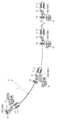
図3は、図1中のモータグレーダの操向に関わる構成を示すシステム図である。図3に示されるように、モータグレーダ100は、操向機構66と、制御部51と、操作部67とをさらに有する。 FIG. 3 is a system diagram showing a configuration related to steering of the motor grader in FIG. 1. As shown in FIG. 3,
操向機構66は、モータグレーダ100の進行方向を操作する機構である。制御部51は、モータグレーダ100の操向を制御する。制御部51は、操向機構66の動作を制御する。操作部67は、キャブ11内に設けられている。操作部67は、操向機構66を動作させるためにオペレータによって操作される。 The
操作部67は、ステアリングハンドル41と、ステアリングレバー42とを有する。ステアリングハンドル41は、キャブ11内の運転席の前方に設けられている。ステアリングハンドル41は、たとえば、ホイール形状のハンドルであり、オペレータによって回転操作される。ステアリングレバー42は、ステアリングハンドル41から離れた位置に設けられている。ステアリングレバー42は、たとえば、キャブ11内の運転席の側方に設けられている。ステアリングレバー42は、オペレータによって傾倒操作される。 The operating
モータグレーダ100は、電気流体圧制御弁73をさらに有する。操作部67は、軌道バルブ71をさらに有する。操向機構66は、ステアリングバルブ72と、ステアリングシリンダ36とを有する。
電気流体圧制御弁73は、圧油をステアリングバルブ72に供給する。制御部51は、ステアリングレバー42からの操作信号に基づいて、電気流体圧制御弁73を制御する。軌道バルブ71は、ステアリングハンドル41における回転操作に応じて、圧油をステアリングバルブ72に供給する。 The
ステアリングバルブ72は、ステアリングシリンダ36に圧油を供給する。ステアリングバルブ72は、電気流体圧制御弁73および軌道バルブ71から供給される圧油により制御される。ステアリングシリンダ36は、ステアリングバルブ72からの圧油により、前輪16の前後方向に対してなす角度を変化させるように前輪16を左右に動作させる。前輪16が左側に傾くと、モータグレーダ100は、左前方に向けて円弧を描きながら旋回する。前輪16が右側に傾くと、モータグレーダ100は、右前方に向けて円弧を描きながら旋回する。 The steering
このような構成により、オペレータがステアリングハンドル41またはステアリングレバー42を操作することによって、ステアリングシリンダ36が伸縮し、前輪16が左右に動作する。 With this configuration, when the operator operates the steering handle 41 or the steering
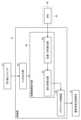
図4は、図1中のモータグレーダの運転アシストシステムに関わる構成を示すブロック図である。図2から図4に示されるように、制御部51は、以下に説明するモータグレーダ100の運転アシストシステムの動作を制御する。 FIG. 4 is a block diagram showing a configuration related to the driving assist system of the motor grader shown in FIG. As shown in FIGS. 2 to 4, the
モータグレーダ100は、ハンドルセンサ31と、レバーセンサ32とをさらに有する。ハンドルセンサ31は、ステアリングハンドル41の操作を検知する。レバーセンサ32は、ステアリングレバー42の操作を検知する。
ハンドルセンサ31は、オペレータによるステアリングハンドル41の操作を検知した場合に操作信号を発生し、操作信号を制御部51に出力する。ハンドルセンサ31は、たとえば、ステアリングハンドル41の回転によって発生するステアリングハンドル軸の角度変位を検出する軸変位センサである。レバーセンサ32は、オペレータによるステアリングレバー42の操作を検知した場合に操作信号を発生し、操作信号を制御部51に出力する。レバーセンサ32は、たとえば、ステアリングレバー42の角度位置を検出する位置センサである。 The
なお、ハンドルセンサ31は、ステアリングハンドル41の回転操作量が微小である場合には、操作信号を発生しないように不感帯を有してもよい。同様に、レバーセンサ32は、ステアリングレバー42の傾倒操作量が微小である場合には、操作信号を発生しないように不感帯を有してもよい。一例として、後述する前輪16のステアリング角度が±0.5°以内で変化する時のステアリングハンドル41またはステアリングレバー42の操作量は、微小であると判断される。 Note that the
モータグレーダ100は、検知部63を有する。検知部63は、モータグレーダ100の位置および向きの少なくともいずれか一方に関する情報を検知する。
検知部63は、慣性計測装置(IMU:Inertial Measurement Unit)38を有する。IMU38は、モータグレーダ100の加速度および角速度を計測するセンサである。IMU38は、モータグレーダ100の加速度および角速度の信号を制御部51に出力する。 The
図4に示されるように、制御部51は、操向機構66の自動制御を開始するためのトリガが入力された場合に、モータグレーダ100の単位走行距離当たりの進行方向の変化率が一定に保たれるように、操向機構66を制御する。 As shown in FIG. 4, when a trigger for starting automatic control of the
制御部51は、操作部67の操作が停止された場合に操向機構66の制御を開始する。制御部51は、操作部67の操作が再開された場合に操向機構66の制御を停止する。 The
制御部51は、トリガ出力部52と、自動制御指令部58と、ステアリング制御部54とを有する。 The
トリガ出力部52は、ハンドルセンサ31からのステアリングハンドル41の操作信号、および/または、レバーセンサ32からのステアリングレバー42の操作信号に基づいて、操向機構66の制御(後述するステアリング自動制御)を開始または停止するためのトリガを出力する。 The
トリガ出力部52は、ハンドルセンサ31からのステアリングハンドル41の操作信号、または、レバーセンサ32からのステアリングレバー42の操作信号が入力された場合に、ステアリング自動制御を停止するためのトリガ(後述する停止トリガ)を出力する。 The
トリガ出力部52は、ハンドルセンサ31からのステアリングハンドル41の操作信号、および、レバーセンサ32からのステアリングレバー42の操作信号が入力されなかった場合に、ステアリング自動制御を開始するためのトリガ(後述する開始トリガ)を出力する。 The
自動制御指令部58は、位置および方向算出部59と、進行方向の変化率算出部57とを有する。 The automatic
位置および方向算出部59には、IMU38により検知されたモータグレーダ100の加速度および角速度の信号が入力される。位置および方向算出部59は、IMU38により計測されたモータグレーダ100の加速度および角速度に基づいて、モータグレーダ100の位置および向きを算出し、算出したモータグレーダ100の位置および向きの信号を変化率算出部57に出力する。 The acceleration and angular velocity signals of the
変化率算出部57には、位置および方向算出部59により算出されたモータグレーダ100の位置および向きの信号が入力される。変化率算出部57は、位置および方向算出部59により算出されたモータグレーダ100の位置および向きに基づいて、モータグレーダ100の単位走行距離当たりの進行方向の変化率を算出する。 The change
ステアリング制御部54は、変化率算出部57により算出されたモータグレーダ100の単位走行距離当たりの進行方向の変化率が一定に保たれるように、操向機構66を制御する。具体的には、ステアリング制御部54は、変化率算出部57により算出されたモータグレーダ100の単位走行距離当たりの進行方向の変化率が一定に保たれるように、電気流体圧制御弁73に制御信号を出力する。電気流体圧制御弁73は、ステアリング制御部54からの信号に基づいて、ステアリングバルブ72に圧油を供給し、ステアリングシリンダ36を制御する(ステアリング自動制御の開始)。 The
オペレータによる操作部67の操作が再開されると、トリガ出力部52には、ハンドルセンサ31からのステアリングハンドル41の操作信号、または、レバーセンサ32からのステアリングレバー42の操作信号が入力される。これにより、トリガ出力部52は、停止トリガを出力する。この場合に、自動制御指令部58は、トリガ出力部52からの停止トリガを受信し、ステアリング自動制御を停止させる。 When the operator resumes operation of the
続いて、制御部51で実行されるステアリング自動制御についてより具体的に説明する。図5は、旋回時にステアリング自動制御が開始されるモータグレーダを模式的に示す上面図である。 Next, automatic steering control executed by the
なお、説明を簡単にするために、図5および後出の図6中には、前輪16を動作させるための操作部67としてステアリングハンドル41のみが用いられる場合が示されている。 In order to simplify the explanation, FIG. 5 and FIG. 6, which will be described later, show a case where only the steering handle 41 is used as the operating
図4および図5に示されるように、モータグレーダ100が、モータグレーダ100A、モータグレーダ100B、モータグレーダ100Cおよびモータグレーダ100Dに示される位置(以下、「位置100A」、「位置100B」、「位置100C」および「位置100D」とそれぞれいう)を順に移動するように走行する。 As shown in FIGS. 4 and 5, the
モータグレーダ100が位置100Aから位置100Bまで移動する間、オペレータは、ステアリングハンドル41を操作することによってモータグレーダ100を走行させている。この間、トリガ出力部52には、ハンドルセンサ31からのステアリングハンドル41の操作信号が入力される。トリガ出力部52は、停止トリガを出力する。自動制御指令部58は、トリガ出力部52からの停止トリガを受信し、ステアリング自動制御は開始されない。 While the
モータグレーダ100が位置100Bから位置100Cまで移動する間、オペレータは、ステアリングハンドル41を操作することによって、モータグレーダ100を右前方に向けて旋回させる。この間、トリガ出力部52には、ハンドルセンサ31からのステアリングハンドル41の操作信号が入力される。トリガ出力部52は、停止トリガを出力する。自動制御指令部58は、トリガ出力部52からの停止トリガを受信し、ステアリング自動制御は開始されない。 While the
モータグレーダ100が位置100Cから位置100Dまで移動する間、オペレータは、ステアリングハンドル41を操作していない。この間、トリガ出力部52には、ハンドルセンサ31からのステアリングハンドル41の操作信号が入力されない。トリガ出力部52は、開始トリガを出力する。自動制御指令部58は、トリガ出力部52からの開始トリガを受信し、ステアリング自動制御が開始される。 The operator is not operating the steering handle 41 while the
トリガ出力部52にハンドルセンサ31からのステアリングハンドル41の操作信号が入力されない場合、トリガ出力部52は開始トリガを出力する。位置および方向算出部59は、IMU38により計測されたモータグレーダ100の加速度および角速度に基づいて、モータグレーダ100の位置および向きを算出し、変化率算出部57に出力する。変化率算出部57は、位置および方向算出部59により算出されたモータグレーダ100の位置および向きに基づいて、モータグレーダ100の単位走行距離当たりの進行方向の変化率を算出する。モータグレーダ100の単位走行距離当たりの進行方向の変化率とは、モータグレーダ100が単位走行距離(たとえば、1m)を走行する毎のモータグレーダ100の向き(たとえば、モータグレーダ100の前方に対応する方向)の変化量(角度)である。 When the
位置100Cから位置100Dまでのステアリング自動制御が実行される間、ステアリング制御部54は、モータグレーダ100が単位走行距離を走行する毎のモータグレーダ100の向きの変化量が、一定の角度となるように、ステアリングシリンダ36を制御する。モータグレーダ100は、ステアリング制御部54によるステアリング自動制御によって、一定の曲率半径rを維持しながら旋回移動する。 While the automatic steering control from
このあと、ステアリング制御部54は、トリガ出力部52にハンドルセンサ31からのステアリングハンドル41の操作信号が入力された場合には、ステアリング自動制御を停止し、トリガ出力部52にハンドルセンサ31からのステアリングハンドル41の操作信号が入力されない場合には、ステアリング自動制御を再開する。 After that, when the
図6は、直進時にステアリング自動制御が開始されるモータグレーダを模式的に示す上面図である。 FIG. 6 is a top view schematically showing a motor grader in which automatic steering control is started when traveling straight.
図6に示されるように、モータグレーダ100が、モータグレーダ100S、モータグレーダ100Tおよびモータグレーダ100Uに示される位置(以下、「位置100S」、「位置100T」および「位置100U」とそれぞれいう)を順に移動するように走行する。 As shown in FIG. 6, the
モータグレーダ100が位置100Sから位置100Tまで移動する間、オペレータは、ステアリングハンドル41を操作することによってモータグレーダ100を走行させている。この間、トリガ出力部52には、ハンドルセンサ31からのステアリングハンドル41の操作信号が入力される。トリガ出力部52は、停止トリガを出力する。自動制御指令部58は、トリガ出力部52からの停止トリガを受信し、ステアリング自動制御は開始されない。 While the
モータグレーダ100が位置100Tから位置100Uまで移動する間、オペレータは、ステアリングハンドル41を操作していない。この間、トリガ出力部52には、ハンドルセンサ31からのステアリングハンドル41の操作信号が入力されない。トリガ出力部52は、開始トリガを出力する。自動制御指令部58は、トリガ出力部52からの開始トリガを受信し、ステアリング自動制御が開始される。 The operator is not operating the steering handle 41 while the
位置100Tから位置100Uまでのステアリング自動制御が実行される間、ステアリング制御部54は、モータグレーダ100が単位走行距離を走行する毎のモータグレーダ100の向きの変化量がゼロとなるように、ステアリングシリンダ36を制御する。モータグレーダ100は、ステアリング制御部54によるステアリング自動制御によって、一直線に移動する。 While automatic steering control from
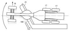
図7は、ブレードに負荷を受けた場合のモータグレーダの挙動を示す上面図である。図7に示されるように、土砂または雪などの堆積物160をモータグレーダ100の側方に寄せるため、ブレード21が左右方向に対して斜めに傾けて使用される。この場合、ブレード21が堆積物160から負荷を受けることによって、モータグレーダ100の進行方向が側方にずれたり、堆積物160からの負荷が変化することによって、モータグレーダ100の進行方向が左右にぶれたりする。また、モータグレーダ100に限られず、作業車両は、一般的に凹凸形状を有した地面上を走行するため、作業車両の進行方向がずれやすい。 FIG. 7 is a top view showing the behavior of the motor grader when a load is applied to the blade. As shown in FIG. 7, in order to move
このため、オペレータは、モータグレーダ100の進行方向を調整するために、ステアリングハンドル41またはステアリングレバー42を操作したり、リーニング操作をしたりしながら、作業機12の操作レバーも操作しなければならない。このような作業は、高い技術と集中力とを必要とするため、オペレータに過度な負担を強いる。 Therefore, in order to adjust the traveling direction of the
これに対して、モータグレーダ100では、自動制御指令部58にステアリング自動制御を開始するためのトリガが入力された場合、ステアリング制御部54がモータグレーダ100の単位走行距離当たりの進行方向の変化率が一定に保たれるようにステアリング自動制御を行なう。 On the other hand, in the
このような構成によれば、オペレータは、ステアリング自動制御が実行される間、モータグレーダ100の進行方向を調整するための操作に行なうことなく、作業機12の操作に集中することができる。また、ステアリング自動制御は、モータグレーダ100の単位走行距離当たりの進行方向の変化率の算出を通じて自動的に実行されるため、オペレータが、事前に作業現場の地図を入力したり、走行経路に関する各種パラメータを入力したりする必要がない。したがって、オペレータの負担が十分に軽減される運転アシストシステムを実現することができる。 According to such a configuration, the operator can concentrate on operating the working
また、制御部51は、ステアリングハンドル41およびステアリングレバー42の操作が停止された場合にステアリング自動制御を開始する。このような構成により、オペレータは、ステアリング自動制御を開始するために特別の操作を行なう必要がないため、オペレータの負担をさらに軽減することができる。 Further, the
さらに、制御部51は、ステアリングハンドル41またはステアリングレバー42の操作が再開された場合にステアリング自動制御を停止する。このような構成により、オペレータは、ステアリングハンドル41またはステアリングレバー42の操作を通じて、モータグレーダ100を意図した方向に走行させることができる。 Further, the
図8は、ハンドル操作と、ステアリング自動制御との相互のタイミングの関係を示すタイミングチャートである。 FIG. 8 is a timing chart showing the mutual timing relationship between steering wheel operation and automatic steering control.
図4および図8に示されるように、制御部51は、ステアリングハンドル41およびステアリングレバー42の操作が停止された状態が所定期間継続された後に、ステアリング自動制御を開始してもよい。 As shown in FIGS. 4 and 8, the
図8に示されるタイミングチャートでは、時間t1において、オペレータがステアリングハンドル41を操作しないことによって、トリガ出力部52にハンドルセンサ31からのステアリングハンドル41の操作信号が入力されない。次に、時間t2において、ステアリング制御部54が、ステアリング自動制御を開始する。 In the timing chart shown in FIG. 8, the operator does not operate the
時間t1から時間t2までの長さは、たとえば、1s以上2s以下の範囲である(1s≦(t2-t1)≦2s)。 The length from time t1 to time t2 is, for example, in a range of 1 s or more and 2 s or less (1 s≦(t2−t1)≦2 s).
このような構成によれば、ステアリングハンドル41およびステアリングレバー42の操作が停止された状態が所定期間継続された後に、ステアリング自動制御が開始されるため、制御部51が、ステアリングハンドル41およびステアリングレバー42の操作の停止に過剰に反応してステアリング自動制御を開始することを防止できる。 According to such a configuration, automatic steering control is started after the operation of the steering handle 41 and the steering
図9は、モータグレーダの制御方法を示すフローチャートである。図4および図9に示されるように、まず、制御部51が、運転アシストモードに設定される(S201)。運転アシストモードの設定は、たとえば、オペレータが、キャブ11内に設けられたモード設定スイッチをオンすることによって行なわれる。 FIG. 9 is a flowchart showing a method of controlling a motor grader. As shown in FIGS. 4 and 9, first, the
次に、ハンドルセンサ31が、オペレータによるステアリングハンドル41の操作の有無を検知し、レバーセンサ32が、オペレータによるステアリングレバー42の操作の有無を検知する(S202)。 Next, the
本ステップにおいて、ハンドルセンサ31がステアリングハンドル41の操作を検知した場合、ステアリングハンドル41の操作信号がトリガ出力部52に入力され、ハンドルセンサ31がステアリングハンドル41の操作を検知しなかった場合、ステアリングハンドル41の操作信号がトリガ出力部52に入力されない。レバーセンサ32がステアリングレバー42の操作を検知した場合、ステアリングレバー42の操作信号がトリガ出力部52に入力され、レバーセンサ32がステアリングレバー42の操作を検知しなかった場合、ステアリングレバー42の操作信号がトリガ出力部52に入力されない。 In this step, when the
次に、自動制御指令部58が、ステアリング自動制御を開始するか否かを判断する(S203)。 Next, the automatic
S202のステップにおいて、ハンドルセンサ31からのステアリングハンドル41の操作信号、または、レバーセンサ32からのステアリングレバー42の操作信号がトリガ出力部52に入力された場合、トリガ出力部52が自動制御指令部58に停止トリガを出力する。この場合、自動制御指令部58は、ステアリング自動制御を開始しないと判断する。次に、S202のステップに戻る。 In step S202, when the
S202のステップにおいて、ハンドルセンサ31からのステアリングハンドル41の操作信号、および、レバーセンサ32からのステアリングレバー42の操作信号がトリガ出力部52に入力されない場合、トリガ出力部52が自動制御指令部58に開始トリガを出力する。この場合、自動制御指令部58は、ステアリング自動制御を開始すると判断する(S203)。次に、S204のステップに進む。 In step S202, if the operation signal for the
位置および方向算出部59は、IMU38により計測されたモータグレーダの加速度および角速度に基づいて、モータグレーダの位置および向きを算出する。変化率算出部57は、位置および方向算出部59により算出されたモータグレーダの位置および向きに基づいて、モータグレーダの単位走行距離当たりの進行方向の変化率を算出する(S204)。ステアリング制御部54は、変化率算出部57により算出されたモータグレーダの単位走行距離当たりの進行方向の変化率が一定に保たれるように、ステアリングシリンダ36を制御する(S205)。 The position and
S205のステップを開始した後、ハンドルセンサ31が、オペレータによるステアリングハンドル41の操作の有無を検知し、レバーセンサ32が、オペレータによるステアリングレバー42の操作の有無を検知するS206のステップと、自動制御指令部58が、ステアリング自動制御を停止するか否かを判断するS207のステップとを継続して実行する。S207のステップにおいて、ステアリング自動制御を停止すると判断された場合、ステアリング制御部54は、ステアリング自動制御を停止する(S208)。そのあと、S202のステップに戻る。 After starting step S205, the
図10は、図4中の運転アシストシステムに関わる構成の変形例を示すブロック図である。図10に示されるように、本変形例では、モータグレーダ100は、切り替えスイッチ37を有する。切り替えスイッチ37は、ステアリング自動制御の開始(オン)と、ステアリング自動制御の停止(オフ)とを切り替えるためのスイッチである。 FIG. 10 is a block diagram showing a modification of the configuration related to the driving assist system in FIG. 4. In FIG. As shown in FIG. 10, in this modification, the
切り替えスイッチ37は、キャブ11内に設けられている。切り替えスイッチ37の形態は、特に限定されず、たとえば、押しボタンであってもよいし、レバーであってもよい。切り替えスイッチ37は、モニタにおけるタッチパネル内に設けられてもよい。 The
本変形例においては、オペレータによって切り替えスイッチ37がオン操作されると、自動制御指令部58にステアリング自動制御を開始するためのトリガ(開始トリガ)が入力される。続いて、モータグレーダの単位走行距離当たりの進行方向の変化率の算出と、ステアリング自動制御とが実行される。オペレータによって切り替えスイッチ37がオフ操作されると、自動制御指令部58に停止トリガが入力され、ステアリング自動制御が停止される。 In this modification, when the operator turns on the
このような構成によれば、オペレータは、より自らが意図したタイミングでステアリング自動制御を開始させることができる。 According to such a configuration, the operator can start the automatic steering control at a timing that the operator intends.
以上に説明した、本実施の形態におけるモータグレーダ100およびその制御方法の構成および効果についてまとめて説明する。 The configuration and effects of the
作業車両としてのモータグレーダ100は、操向機構66と、制御部51とを備える。制御部51は、モータグレーダ100の単位走行距離当たりの進行方向の変化率が一定に保たれるように、操向機構66を制御する。 The
このような構成によれば、制御部51は、モータグレーダ100の単位走行距離当たりの進行方向の変化率が一定に保たれるように操向機構66を制御するため、オペレータに煩雑な作業が求められない。このため、オペレータの負担が十分に軽減される運転アシストシステムを実現することができる。 According to such a configuration, the
また、制御部51は、操向機構66の制御を開始するためのトリガが入力された場合に、モータグレーダ100の単位走行距離当たりの進行方向の変化率が一定に保たれるように、操向機構66を制御する。 Furthermore, when a trigger for starting control of the
このような構成によれば、制御部51は、予め定められたトリガに基づいて、操向機構66の制御を開始するか否かを判断することができる。 According to such a configuration, the
また、モータグレーダ100は、操作部67をさらに備える。操作部67は、操向機構66を動作させるために操作される。制御部51は、操作部67の操作が停止された場合に操向機構66の制御を開始する。 Further, the
このような構成によれば、操向機構66の制御を開始するためのオペレータの操作が不要であるため、オペレータの負担をさらに軽減することができる。 According to such a configuration, the operator's operation for starting control of the
また、制御部51は、操作部67の操作が停止された状態が所定期間継続された後に、操向機構66の制御を開始してもよい。 Further, the
このような構成によれば、制御部51が操作部67の操作の停止に過剰に反応して操向機構66の制御を開始することを防止できる。 According to such a configuration, it is possible to prevent the
また、制御部51は、操作部67の操作が再開された場合に操向機構66の制御を停止する。 Further, the
このような構成によれば、操作部67の操作が再開された場合にはその操作によって操向機構66を動作させることにより、オペレータは、モータグレーダ100を自らの意図した方向に走行させることができる。 According to such a configuration, when the operation of the
また、モータグレーダ100は、制御部51による操向機構66の制御の開始および停止を切り替えるためのスイッチとしての切り替えスイッチ37を備えてもよい。 Further, the
このような構成によれば、オペレータは、より自らが意図したタイミングで、制御部51による操向機構66の制御を開始させることができる。 According to such a configuration, the operator can start controlling the
また、モータグレーダ100は、検知部63をさらに備える。検知部63は、モータグレーダ100の位置および向きの少なくともいずれか一方に関する情報を検知する。制御部51は、検知部63により検知されたモータグレーダ100の位置および向きの少なくともいずれか一方に関する情報に基づいて、モータグレーダ100の単位走行距離当たりの進行方向の変化率を特定する。 Furthermore, the
このような構成によれば、制御部51は、検知部63において検知されたモータグレーダ100の位置および向きの少なくともいずれか一方に関する情報を用いて、モータグレーダ100の進行方向の変化率を特定することができる。 According to such a configuration, the
モータグレーダ100の制御方法は、モータグレーダ100の単位走行距離当たりの進行方向の変化率を算出するステップ(S204)と、算出されたモータグレーダ100の単位走行距離当たりの進行方向の変化率が一定に保たれるように、操向機構66を制御するステップ(S205)とを備える。 The control method for the
算出するステップ(S204)は、操向機構66の制御を開始するためのトリガが入力された場合に、モータグレーダ100の単位走行距離当たりの進行方向の変化率を算出するステップを含む。 The calculating step (S204) includes calculating the rate of change in the traveling direction of the
このような構成によれば、オペレータの負担が十分に軽減される運転アシストシステムを実現することができる。 According to such a configuration, it is possible to realize a driving assist system in which the burden on the operator is sufficiently reduced.
なお、本開示における検知部としては、上記のIMUに限られず、ジャイロセンサ、地磁気センサまたはカメラなどを用いることも可能である。本開示における検知部としてカメラを用いた場合、カメラにより撮影されるモータグレーダの周囲の画像を解析することによって、モータグレーダの位置および向きを検知することができる。 Note that the detection unit in the present disclosure is not limited to the above-mentioned IMU, but may also be a gyro sensor, a geomagnetic sensor, a camera, or the like. When a camera is used as the detection unit in the present disclosure, the position and orientation of the motor grader can be detected by analyzing an image around the motor grader taken by the camera.
モータグレーダ100は、モータグレーダ100の進行方向を操作する操向機構66として、前輪16を左右に傾倒させるリーニング機構と、フロントフレーム14とリアフレーム15とを屈曲させるアーティキュレート機構とをさらに有する。制御部51によって実行される操向機構66の制御は、ステアリング自動制御に限られず、リーニング機構の自動制御であってもよいし、アーティキュレート機構の自動制御であってもよいし、ステアリング機構、リーニング機構およびアーティキュレート機構のうちの複数の機構の自動制御であってもよい。 The
本開示における作業車両およびその制御方法は、モータグレーダに限られず、たとえば、ホイールローダ、ダンプトラックまたはブルドーザなどの各種の作業車両に適用されてもよい。ホイールローダへの適用の場合、制御部による制御の対象は、回動可能に接続されたフロントフレームとリアフレームとのアーティキュレート角度であってもよい。 The work vehicle and its control method in the present disclosure are not limited to motor graders, and may be applied to various work vehicles such as wheel loaders, dump trucks, or bulldozers. In the case of application to a wheel loader, the object to be controlled by the control unit may be the articulation angle of a rotatably connected front frame and rear frame.
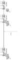
図11は、モータグレーダの操向機構の制御システムの概念を示す図である。上記の実施の形態では、作業車両であるモータグレーダ100が制御部51を備える場合を説明したが、図3および図11に示されるように、モータグレーダの操向機構66が、モータグレーダから離れた位置に設けられた制御部および操作部によって制御される構成であってもよい。 FIG. 11 is a diagram showing the concept of a control system for a steering mechanism of a motor grader. In the above embodiment, a case has been described in which the
モータグレーダの操向機構66を制御する制御システムは、モータグレーダの単位走行距離当たりの進行方向の変化率が一定に保たれるように、モータグレーダの操向機構66を制御する制御部251を備える。 The control system that controls the
(実施の形態2)
本実施の形態では、実施の形態1において説明した運転アシストシステムがブルドーザに適用された場合の構成を説明する。以下、実施の形態1における構成と重複する構成については、その説明を繰り返さない。(Embodiment 2)
In this embodiment, a configuration in which the driving assist system described in
図12は、ブルドーザを示す斜視図である。図13は、図12中のブルドーザの操向に関わる構成を示すシステム図である。 FIG. 12 is a perspective view of the bulldozer. FIG. 13 is a system diagram showing a configuration related to steering of the bulldozer in FIG. 12.
図12に示されるように、ブルドーザ300は、車体311と、作業機313と、左右一対の牽引装置316(316R,316L)とを有する。車体311は、左右一対の牽引装置316(316R,316L)上に設けられている。車体311は、キャブ341と、エンジン室342とを有する。作業機313は、車体311の前方に設けられている。作業機313は、土砂の掘削および整地などの作業を行なうためのブレード318を有する。 As shown in FIG. 12, the
左右一対の牽引装置316(316R,316L)は、ブルドーザ300を走行させるための装置である。左右一対の牽引装置316(316R,316L)は、たとえば、履帯と、終減速装置とを有する。左右一対の牽引装置316(316R,316L)が回転駆動されることによって、ブルドーザ300が走行する。 A pair of left and right traction devices 316 (316R, 316L) are devices for driving the
図12および図13に示されるように、ブルドーザ300は、操向機構66と、制御部51と、操作部67と、電気流体圧制御弁73とを有する。 As shown in FIGS. 12 and 13, the
操向機構66は、駆動装置331を有する。駆動装置331は、油圧により作動する油圧モータである。駆動装置331は、右側の牽引装置(第1牽引装置)316Rと、左側の牽引装置(第2牽引装置)316Lとを互いに独立して駆動させることが可能である。 The
操作部67は、ステアリングレバー42を有する。電気流体圧制御弁73は、圧油を駆動装置331に供給する。制御部51は、ステアリングレバー42からの操作信号に基づいて、電気流体圧制御弁73を制御する。駆動装置331は、電気流体圧制御弁73からの圧油により、右側の牽引装置316Rと、左側の牽引装置316Lとを回転させる。右側の牽引装置316Rの回転速度と、左側の牽引装置316Lの回転速度とが同じである場合、ブルドーザ300が直進する。右側の牽引装置316Rの回転速度が、左側の牽引装置316Lの回転速度よりも大きい場合、ブルドーザ300が左前方に向けて旋回する。左側の牽引装置316Lの回転速度が、右側の牽引装置316Rの回転速度よりも大きい場合、ブルドーザ300が右前方に向けて旋回する。 The operating
図14は、図12中のブルドーザの運転アシストシステムに関わる構成を示すブロック図である。図13および図14に示されるように、ブルドーザ300は、レバーセンサ32を有する。レバーセンサ32は、ステアリングレバー42の操作を検知する。 FIG. 14 is a block diagram showing a configuration related to the driving assist system of the bulldozer shown in FIG. 12. As shown in FIGS. 13 and 14,
ブルドーザ300は、検知部63をさらに有する。検知部63は、ブルドーザ300の位置および向きの少なくともいずれか一方に関する情報を検知する。検知部63は、IMU38を有する。IMU38は、ブルドーザ300の加速度および角速度を計測するセンサである。IMU38は、ブルドーザ300の加速度および角速度の信号を制御部51に出力する。
図14に示されるように、制御部51は、トリガ出力部52と、自動制御指令部58と、ステアリング制御部54とを有する。 As shown in FIG. 14, the
トリガ出力部52は、レバーセンサ32からのステアリングレバー42の操作信号に基づいて、操向機構66の制御を開始または停止するためのトリガを出力する。 The
自動制御指令部58は、位置および方向算出部59と、進行方向の変化率算出部57とを有する。 The automatic
位置および方向算出部59には、IMU38により検知されたブルドーザ300の加速度および角速度の信号が入力される。位置および方向算出部59は、IMU38により計測されたブルドーザ300の加速度および角速度に基づいて、ブルドーザ300の位置および向きを算出し、算出したブルドーザ300の位置および向きの信号を変化率算出部57に出力する。 The acceleration and angular velocity signals of the
変化率算出部57には、位置および方向算出部59により算出されたブルドーザ300の位置および向きの信号が入力される。変化率算出部57は、位置および方向算出部59により算出されたブルドーザ300の位置および向きに基づいて、ブルドーザ300の単位走行距離当たりの進行方向の変化率を算出する。 A signal indicating the position and orientation of the
ステアリング制御部54は、変化率算出部57により算出されたブルドーザ300の単位走行距離当たりの進行方向の変化率が一定に保たれるように、操向機構66を制御する。具体的には、ステアリング制御部54は、変化率算出部57により算出されたブルドーザ300の単位走行距離当たりの進行方向の変化率が一定に保たれるように、電気流体圧制御弁73に制御信号を出力する。電気流体圧制御弁73は、ステアリング制御部54から信号に基づいて、駆動装置331に圧油を供給し、右側の牽引装置316Rの回転速度と、左側の牽引装置316Lの回転速度とを制御する。 The
このように構成されたブルドーザ300によれば、実施の形態1に記載の効果を同様に奏することができる。 According to
今回開示された実施の形態はすべての点で例示であって制限的なものではないと考えられるべきである。本発明の範囲は上記した説明ではなくて特許請求の範囲によって示され、特許請求の範囲と均等の意味および範囲内でのすべての変更が含まれることが意図される。 The embodiments disclosed this time should be considered to be illustrative in all respects and not restrictive. The scope of the present invention is indicated by the claims rather than the above description, and it is intended that all changes within the meaning and range equivalent to the claims are included.
11,341 キャブ、12,313 作業機、13,342 エンジン室、14 フロントフレーム、14p 基端部、14q 先端部、15 リアフレーム、16 前輪、17 後輪、18 車体フレーム、21,318 ブレード、22 ドローバ、23 旋回サークル、25 リフトシリンダ、28 アーティキュレートシリンダ、31 ハンドルセンサ、32 レバーセンサ、36 ステアリングシリンダ、37 切り替えスイッチ、41 ステアリングハンドル、42 ステアリングレバー、51,251 制御部、52 トリガ出力部、54 ステアリング制御部、57 変化率算出部、58 自動制御指令部、59 方向算出部、63 検知部、66 操向機構、67 操作部、71 軌道バルブ、72 ステアリングバルブ、73 電気流体圧制御弁、100 モータグレーダ、121 回動中心、160 堆積物、300 ブルドーザ、311 車体、316,316L,316R 牽引装置、331 駆動装置。 11,341 Cab, 12,313 Work equipment, 13,342 Engine room, 14 Front frame, 14p Base end, 14q Tip end, 15 Rear frame, 16 Front wheel, 17 Rear wheel, 18 Body frame, 21,318 Blade, 22 drawbar, 23 turning circle, 25 lift cylinder, 28 articulate cylinder, 31 handle sensor, 32 lever sensor, 36 steering cylinder, 37 changeover switch, 41 steering handle, 42 steering lever, 51, 251 control section, 52 trigger output section , 54 steering control section, 57 rate of change calculation section, 58 automatic control command section, 59 direction calculation section, 63 detection section, 66 steering mechanism, 67 operation section, 71 orbital valve, 72 steering valve, 73 electric fluid pressure control valve , 100 motor grader, 121 rotation center, 160 deposit, 300 bulldozer, 311 vehicle body, 316, 316L, 316R traction device, 331 drive device.
Claims (16)
Translated fromJapanese前記制御システムは、制御部を有し、
前記制御部は、オペレータにより前記作業車両の操向機構の制御を開始するためのトリガが入力された場合に、前記作業車両の単位走行距離当たりの進行方向の変化率を算出するとともに、算出した前記作業車両の単位走行距離当たりの進行方向の変化率が一定に保たれるように、前記作業車両の操向機構を制御する、制御システム。A controlsystem for controlling a steering mechanism of a work vehicle, including a steering mechanism and an operation section operated by an operator to operate the steering mechanism, the control system comprising:
The control system includes a control unit,
The control unit calculates a rate of change in the traveling direction of the work vehicle per unit traveling distance when an operator inputs a trigger to start controlling a steering mechanism of the work vehicle, and A control system thatcontrols a steering mechanism of the work vehicle so that a rate of change in the traveling direction of the work vehicle per unit traveling distance is kept constant.
オペレータにより前記作業車両の操向機構の制御を開始するためのトリガが入力された場合に、前記作業車両の単位走行距離当たりの進行方向の変化率を算出するステップと、
算出された前記作業車両の単位走行距離当たりの進行方向の変化率が一定に保たれるように、前記操向機構を制御するステップとを備える、作業車両の制御方法。A method for controlling a work vehicle, the method comprising: a steering mechanism; and an operation section operated by an operator to operate the steering mechanism, the method comprising:
calculating a rate of change in the travelingdirection of the work vehicle per unit traveling distance when a trigger for starting control of the steering mechanism of the work vehicle is input by an operator;
A method for controlling a work vehicle, comprising the step of controlling the steering mechanism so that the calculated rate of change in the traveling direction per unit traveling distance of the work vehicle is kept constant.
前記ステアリングシリンダは、前記ステアリングバルブからの圧油により、前後方向に対して操向輪がなす角度が変化するように前記操向輪を動作させる、請求項6に記載の作業車両の制御方法。The steering mechanism includes a steering cylinder and a steering valve that controls the steering cylinder,
7. The method of controlling a work vehicle according to claim6 , wherein the steering cylinder operates the steering wheel so that the angle formed by the steering wheel with respect to the front-rear direction changes using pressure oil from the steering valve.
前記駆動装置は、前記第1牽引装置の回転速度と、前記第2牽引装置の回転速度とを互いに独立して制御する、請求項6に記載の作業車両の制御方法。The steering mechanism includes a drive device that rotationally drives a pair of left and right first traction devices and a second traction device,
7. The method for controlling a work vehicle according to claim6 , wherein the drive device controls the rotational speed of the first traction device and the rotational speed of the second traction device independently of each other.
操向機構と、
前記操向機構を動作させるためにオペレータによって操作される操作部と、
制御部とを備え、
前記制御部は、オペレータにより前記操向機構の制御を開始するためのトリガが入力された場合に、前記作業車両の単位走行距離当たりの進行方向の変化率を算出するとともに、算出した前記作業車両の単位走行距離当たりの進行方向の変化率が一定に保たれるように、前記操向機構を制御する、作業車両。A work vehicle,
a steering mechanism;
an operating section operated by an operator to operate the steering mechanism;
It is equipped with a control section,
The control unit calculates a rate of change in the traveling direction of the work vehicle per unit traveling distance when a trigger for starting control of the steering mechanism is input by an operator, and the control unit calculates a rate of change in the traveling direction of the work vehicle per unit traveling distance. A work vehicle, wherein the steering mechanismis controlled so that a rate of change in a traveling direction per unit traveling distance of the work vehicle is maintained constant.
前記制御部は、前記検知部により検知された前記作業車両の位置および向きの少なくともいずれか一方に関する情報に基づいて、前記作業車両の単位走行距離当たりの進行方向の変化率を特定する、請求項9から13のいずれか1項に記載の作業車両。further comprising a detection unit that detects information regarding at least one of the position and orientation of the work vehicle,
The control unit specifies a rate of change in the traveling direction of the work vehicle per unit traveling distance based on information regarding at least one of the position and orientation of the work vehicle detected by the detection unit. The work vehicle according to any one of Items9 to 13 .
前記ステアリングシリンダは、前記ステアリングバルブからの圧油により、前後方向に対して操向輪がなす角度が変化するように前記操向輪を動作させる、請求項9から14のいずれか1項に記載の作業車両。The steering mechanism includes a steering cylinder and a steering valve that controls the steering cylinder,
15. The steering cylinder operates the steering wheel so that the angle formed by the steering wheel with respect to the front-rear direction changes using pressure oil from the steering valve. work vehicle.
前記駆動装置は、前記第1牽引装置の回転速度と、前記第2牽引装置の回転速度とを互いに独立して制御する、請求項9から14のいずれか1項に記載の作業車両。The steering mechanism includes a drive device that rotationally drives a pair of left and right first traction devices and a second traction device,
The work vehicle according to any one of claims9 to 14 , wherein the drive device controls the rotation speed of the first traction device and the rotation speed of the second traction device independently of each other.
Priority Applications (4)
| Application Number | Priority Date | Filing Date | Title |
|---|---|---|---|
| JP2019179568AJP7358164B2 (en) | 2019-09-30 | 2019-09-30 | Control system, work vehicle control method, and work vehicle |
| CN202080056877.6ACN114207223A (en) | 2019-09-30 | 2020-07-07 | Control system, control method for work vehicle, and work vehicle |
| US17/638,236US12188205B2 (en) | 2019-09-30 | 2020-07-07 | Control system, method of controlling work vehicle, and work vehicle |
| PCT/JP2020/026508WO2021065135A1 (en) | 2019-09-30 | 2020-07-07 | Control system, work vehicle control method, and work vehicle |
Applications Claiming Priority (1)
| Application Number | Priority Date | Filing Date | Title |
|---|---|---|---|
| JP2019179568AJP7358164B2 (en) | 2019-09-30 | 2019-09-30 | Control system, work vehicle control method, and work vehicle |
Publications (2)
| Publication Number | Publication Date |
|---|---|
| JP2021054270A JP2021054270A (en) | 2021-04-08 |
| JP7358164B2true JP7358164B2 (en) | 2023-10-10 |
Family
ID=75269589
Family Applications (1)
| Application Number | Title | Priority Date | Filing Date |
|---|---|---|---|
| JP2019179568AActiveJP7358164B2 (en) | 2019-09-30 | 2019-09-30 | Control system, work vehicle control method, and work vehicle |
Country Status (4)
| Country | Link |
|---|---|
| US (1) | US12188205B2 (en) |
| JP (1) | JP7358164B2 (en) |
| CN (1) | CN114207223A (en) |
| WO (1) | WO2021065135A1 (en) |
Families Citing this family (4)
| Publication number | Priority date | Publication date | Assignee | Title |
|---|---|---|---|---|
| JP7705291B2 (en)* | 2021-07-16 | 2025-07-09 | 株式会社小松製作所 | Work machine and method for controlling a work machine |
| JP7609727B2 (en)* | 2021-07-16 | 2025-01-07 | 株式会社小松製作所 | Work machine and method for controlling a work machine |
| JP2023090395A (en)* | 2021-12-17 | 2023-06-29 | 株式会社小松製作所 | WORK MACHINE, METHOD AND SYSTEM FOR CONTROLLING WORK MACHINE |
| WO2025187259A1 (en)* | 2024-03-04 | 2025-09-12 | 株式会社小松製作所 | Motor grader and method for calculating drawbar attitude of motor grader |
Citations (3)
| Publication number | Priority date | Publication date | Assignee | Title |
|---|---|---|---|---|
| JP2007060982A (en) | 2005-08-31 | 2007-03-15 | Iseki & Co Ltd | Automatic control device for work vehicle |
| JP2013201958A (en) | 2012-03-28 | 2013-10-07 | National Agriculture & Food Research Organization | Travel control apparatus |
| JP2018069753A (en) | 2016-10-24 | 2018-05-10 | アイシン・エィ・ダブリュ株式会社 | Driving condition display system and driving condition display program |
Family Cites Families (19)
| Publication number | Priority date | Publication date | Assignee | Title |
|---|---|---|---|---|
| JPS5251633A (en)* | 1975-10-24 | 1977-04-25 | Komatsu Forklift Kk | Steering device for industrial vehicle |
| JPS5853927Y2 (en)* | 1977-02-23 | 1983-12-08 | ヤンマー農機株式会社 | Combine automatic steering device |
| JPS6454513A (en)* | 1987-08-25 | 1989-03-02 | Iseki Agricult Mach | Steering controller |
| JP2602065B2 (en)* | 1988-06-21 | 1997-04-23 | 本田技研工業株式会社 | Travel position control device for self-propelled vehicles |
| JPH07172334A (en)* | 1993-12-21 | 1995-07-11 | Kubota Corp | Steering control device |
| US6539303B2 (en)* | 2000-12-08 | 2003-03-25 | Mcclure John A. | GPS derived swathing guidance system |
| US6434462B1 (en)* | 2001-06-28 | 2002-08-13 | Deere & Company | GPS control of a tractor-towed implement |
| US7142956B2 (en)* | 2004-03-19 | 2006-11-28 | Hemisphere Gps Llc | Automatic steering system and method |
| CN100425494C (en)* | 2004-03-26 | 2008-10-15 | 株式会社小松制作所 | Traveling control device and traveling control program for work vehicle or control device and control program for work vehicle |
| US8060299B2 (en) | 2007-02-28 | 2011-11-15 | Caterpillar Inc. | Machine with automated steering system |
| EP1972486A1 (en)* | 2007-03-19 | 2008-09-24 | Invacare International Sàrl | Motorized wheelchair |
| JP5390749B2 (en) | 2007-03-29 | 2014-01-15 | 株式会社小松製作所 | Motor grader and clutch control method for motor grader |
| JP6371137B2 (en)* | 2014-06-27 | 2018-08-08 | 株式会社クボタ | Planting field work machine |
| JP6473091B2 (en)* | 2016-02-09 | 2019-02-20 | ヤンマー株式会社 | Work vehicle |
| JP6932655B2 (en)* | 2017-02-08 | 2021-09-08 | ヤンマーパワーテクノロジー株式会社 | Work vehicle |
| CN108297877B (en) | 2017-10-10 | 2019-08-13 | 腾讯科技(深圳)有限公司 | Control method for vehicle, system and device |
| US12000702B2 (en)* | 2018-12-19 | 2024-06-04 | Honeywell International Inc. | Dynamic gyroscope bias offset compensation |
| US20210010240A1 (en)* | 2019-07-09 | 2021-01-14 | Cnh Industrial America Llc | System and method for controlling the operation of a work vehicle based on a desired turning radius |
| US11673619B2 (en)* | 2019-09-04 | 2023-06-13 | Deere & Company | Articulated work vehicle with steering selection |
- 2019
- 2019-09-30JPJP2019179568Apatent/JP7358164B2/enactiveActive
- 2020
- 2020-07-07CNCN202080056877.6Apatent/CN114207223A/enactivePending
- 2020-07-07USUS17/638,236patent/US12188205B2/enactiveActive
- 2020-07-07WOPCT/JP2020/026508patent/WO2021065135A1/ennot_activeCeased
Patent Citations (3)
| Publication number | Priority date | Publication date | Assignee | Title |
|---|---|---|---|---|
| JP2007060982A (en) | 2005-08-31 | 2007-03-15 | Iseki & Co Ltd | Automatic control device for work vehicle |
| JP2013201958A (en) | 2012-03-28 | 2013-10-07 | National Agriculture & Food Research Organization | Travel control apparatus |
| JP2018069753A (en) | 2016-10-24 | 2018-05-10 | アイシン・エィ・ダブリュ株式会社 | Driving condition display system and driving condition display program |
Also Published As
| Publication number | Publication date |
|---|---|
| US20220298749A1 (en) | 2022-09-22 |
| US12188205B2 (en) | 2025-01-07 |
| JP2021054270A (en) | 2021-04-08 |
| WO2021065135A1 (en) | 2021-04-08 |
| CN114207223A (en) | 2022-03-18 |
Similar Documents
| Publication | Publication Date | Title |
|---|---|---|
| JP7358164B2 (en) | Control system, work vehicle control method, and work vehicle | |
| JP7358163B2 (en) | Control system, work vehicle control method, and work vehicle | |
| CA2994407C (en) | Joystick controller for power machine | |
| JP7544645B2 (en) | Traveling system for working machine and control method for working machine | |
| JP7490127B2 (en) | MOTOR GRADER AND DISPLAY CONTROL METHOD | |
| WO2017164056A1 (en) | Control method for motor graders and motor grader | |
| JP7096388B1 (en) | Construction machinery | |
| US20240337089A1 (en) | Work machine and method for controlling work machine | |
| JP7197342B2 (en) | WORKING MACHINE, SYSTEM INCLUDING WORKING MACHINE, AND CONTROL METHOD FOR WORKING MACHINE | |
| US20230129397A1 (en) | Work vehicle implement joint orientation system and method | |
| CN115003884B (en) | Work vehicle and control method | |
| JP6689639B2 (en) | Control method in motor grader and motor grader | |
| US20240295096A1 (en) | System and method for controlling work machine | |
| JP7609727B2 (en) | Work machine and method for controlling a work machine | |
| EP4520873A1 (en) | Systems and methods for grade control window activation | |
| US20250305238A1 (en) | Work machine and method for controlling work machine | |
| WO2024084791A1 (en) | Work machine and method for controlling work machine | |
| WO2023067886A1 (en) | Control device for work machine | |
| CN117980565A (en) | Work machine, method and system for controlling work machine |
Legal Events
| Date | Code | Title | Description |
|---|---|---|---|
| A621 | Written request for application examination | Free format text:JAPANESE INTERMEDIATE CODE: A621 Effective date:20220808 | |
| A131 | Notification of reasons for refusal | Free format text:JAPANESE INTERMEDIATE CODE: A131 Effective date:20230418 | |
| A521 | Request for written amendment filed | Free format text:JAPANESE INTERMEDIATE CODE: A523 Effective date:20230614 | |
| TRDD | Decision of grant or rejection written | ||
| A01 | Written decision to grant a patent or to grant a registration (utility model) | Free format text:JAPANESE INTERMEDIATE CODE: A01 Effective date:20230919 | |
| A61 | First payment of annual fees (during grant procedure) | Free format text:JAPANESE INTERMEDIATE CODE: A61 Effective date:20230927 | |
| R151 | Written notification of patent or utility model registration | Ref document number:7358164 Country of ref document:JP Free format text:JAPANESE INTERMEDIATE CODE: R151 |