JP7357523B2 - Dispenser - Google Patents
DispenserDownload PDFInfo
- Publication number
- JP7357523B2 JP7357523B2JP2019216959AJP2019216959AJP7357523B2JP 7357523 B2JP7357523 B2JP 7357523B2JP 2019216959 AJP2019216959 AJP 2019216959AJP 2019216959 AJP2019216959 AJP 2019216959AJP 7357523 B2JP7357523 B2JP 7357523B2
- Authority
- JP
- Japan
- Prior art keywords
- stem
- head
- cylinder
- ejection head
- biasing member
- Prior art date
- Legal status (The legal status is an assumption and is not a legal conclusion. Google has not performed a legal analysis and makes no representation as to the accuracy of the status listed.)
- Active
Links
Images


Classifications
- B—PERFORMING OPERATIONS; TRANSPORTING
- B05—SPRAYING OR ATOMISING IN GENERAL; APPLYING FLUENT MATERIALS TO SURFACES, IN GENERAL
- B05B—SPRAYING APPARATUS; ATOMISING APPARATUS; NOZZLES
- B05B11/00—Single-unit hand-held apparatus in which flow of contents is produced by the muscular force of the operator at the moment of use
- B05B11/01—Single-unit hand-held apparatus in which flow of contents is produced by the muscular force of the operator at the moment of use characterised by the means producing the flow
- B05B11/10—Pump arrangements for transferring the contents from the container to a pump chamber by a sucking effect and forcing the contents out through the dispensing nozzle
- B05B11/1042—Components or details
- B05B11/1043—Sealing or attachment arrangements between pump and container
- B05B11/1046—Sealing or attachment arrangements between pump and container the pump chamber being arranged substantially coaxially to the neck of the container
- B05B11/1047—Sealing or attachment arrangements between pump and container the pump chamber being arranged substantially coaxially to the neck of the container the pump being preassembled as an independent unit before being mounted on the container
- B—PERFORMING OPERATIONS; TRANSPORTING
- B05—SPRAYING OR ATOMISING IN GENERAL; APPLYING FLUENT MATERIALS TO SURFACES, IN GENERAL
- B05B—SPRAYING APPARATUS; ATOMISING APPARATUS; NOZZLES
- B05B11/00—Single-unit hand-held apparatus in which flow of contents is produced by the muscular force of the operator at the moment of use
- B05B11/0005—Components or details
- B05B11/0037—Containers
- B05B11/0039—Containers associated with means for compensating the pressure difference between the ambient pressure and the pressure inside the container, e.g. pressure relief means
- B05B11/0044—Containers associated with means for compensating the pressure difference between the ambient pressure and the pressure inside the container, e.g. pressure relief means compensating underpressure by ingress of atmospheric air into the container, i.e. with venting means
- B—PERFORMING OPERATIONS; TRANSPORTING
- B05—SPRAYING OR ATOMISING IN GENERAL; APPLYING FLUENT MATERIALS TO SURFACES, IN GENERAL
- B05B—SPRAYING APPARATUS; ATOMISING APPARATUS; NOZZLES
- B05B11/00—Single-unit hand-held apparatus in which flow of contents is produced by the muscular force of the operator at the moment of use
- B05B11/01—Single-unit hand-held apparatus in which flow of contents is produced by the muscular force of the operator at the moment of use characterised by the means producing the flow
- B05B11/10—Pump arrangements for transferring the contents from the container to a pump chamber by a sucking effect and forcing the contents out through the dispensing nozzle
- B05B11/1001—Piston pumps
- B05B11/1023—Piston pumps having an outlet valve opened by deformation or displacement of the piston relative to its actuating stem
- B—PERFORMING OPERATIONS; TRANSPORTING
- B05—SPRAYING OR ATOMISING IN GENERAL; APPLYING FLUENT MATERIALS TO SURFACES, IN GENERAL
- B05B—SPRAYING APPARATUS; ATOMISING APPARATUS; NOZZLES
- B05B11/00—Single-unit hand-held apparatus in which flow of contents is produced by the muscular force of the operator at the moment of use
- B05B11/01—Single-unit hand-held apparatus in which flow of contents is produced by the muscular force of the operator at the moment of use characterised by the means producing the flow
- B05B11/10—Pump arrangements for transferring the contents from the container to a pump chamber by a sucking effect and forcing the contents out through the dispensing nozzle
- B05B11/1042—Components or details
- B05B11/1059—Means for locking a pump or its actuation means in a fixed position
- B05B11/106—Means for locking a pump or its actuation means in a fixed position in a retracted position, e.g. in an end-of-dispensing-stroke position
- B—PERFORMING OPERATIONS; TRANSPORTING
- B05—SPRAYING OR ATOMISING IN GENERAL; APPLYING FLUENT MATERIALS TO SURFACES, IN GENERAL
- B05B—SPRAYING APPARATUS; ATOMISING APPARATUS; NOZZLES
- B05B11/00—Single-unit hand-held apparatus in which flow of contents is produced by the muscular force of the operator at the moment of use
- B05B11/01—Single-unit hand-held apparatus in which flow of contents is produced by the muscular force of the operator at the moment of use characterised by the means producing the flow
- B05B11/10—Pump arrangements for transferring the contents from the container to a pump chamber by a sucking effect and forcing the contents out through the dispensing nozzle
- B05B11/1042—Components or details
- B05B11/1073—Springs
- B05B11/1074—Springs located outside pump chambers
Landscapes
- Closures For Containers (AREA)
- Reciprocating Pumps (AREA)
Description
Translated fromJapanese本発明は、吐出器に関する。 The present invention relates to a dispensing device.
吐出容器は、容器本体の口部に吐出器が装着されて構成されている。吐出器は、口部に支持されるシリンダと、ステム及び吐出ヘッドを有し、コイルスプリングによって上方付勢状態で下方移動可能にシリンダに組み合わされる上下動部材と、を備えている(例えば、下記特許文献1参照)。
この構成によれば、上下動部材の押し下げ操作により、吐出ヘッドを介してシリンダ内の内容物を吐出することができるとともに、コイルスプリングによる上下動部材の上方への復元移動に伴ってシリンダ内に内容物を吸い上げることが可能とされている。The discharge container includes a discharge device attached to the mouth of the container body. The discharger includes a cylinder supported at the mouth, and a vertically moving member that has a stem and a discharge head and is combined with the cylinder so that it can move downwardly while being biased upwardly by a coil spring (for example, as described below). (See Patent Document 1).
According to this configuration, by pressing down the vertically movable member, the contents in the cylinder can be discharged through the discharge head, and as the vertically movable member is restored upward by the coil spring, the contents in the cylinder can be discharged. It is said that it is possible to suck up the contents.
ところで、廃棄物を廃棄する際には、例えば環境負荷の低減化、廃棄物の処理効率の向上化等に対応するために、一般的に廃棄物の種類に応じて分別を行った後に廃棄を行っている。この点、使い終わった吐出器を廃棄する際、金属製のコイルスプリングを具備したままの状態では、コイルスプリング以外の構成部品が合成樹脂製であったとしても、いわゆる不燃ごみに該当してしまう。そのため、金属製のコイルスプリングと、それ以外の合成樹脂製の構成部品と、を分別して廃棄することが望まれている。 By the way, when disposing of waste, it is generally done after sorting it according to the type of waste, in order to reduce the environmental impact and improve waste processing efficiency. Is going. In this regard, when disposing of a used discharge device, if it still has a metal coil spring, it will fall under so-called non-burnable waste, even if the components other than the coil spring are made of synthetic resin. . Therefore, it is desired to separate and dispose of metal coil springs and other synthetic resin components.
しかしながら、上述した従来の吐出器では、廃棄時にコイルスプリングを取り外すことが難しく、上述したニーズに対応することができなかった。 However, in the conventional ejector described above, it is difficult to remove the coil spring at the time of disposal, and it has not been possible to meet the above-mentioned needs.
本発明は、付勢部材を廃棄時に簡単に取り外すことができる吐出器を提供することを目的とする。 SUMMARY OF THE INVENTION An object of the present invention is to provide a dispensing device whose biasing member can be easily removed at the time of disposal.
上記課題を解決するために、本発明は以下の手段を提案している。
本発明に係る態様の吐出器は、容器本体における口部の内側に、上方付勢状態で下方移動可能に配設されるステムと、前記ステムが挿入された筒状のシリンダと、前記シリンダの内側で前記ステムの上下動に連係するとともに、前記シリンダの内周面に上下摺動可能に嵌合されたピストンと、前記ステムの上端部に着脱可能に取り付けられ、内容物を吐出する吐出口を有する吐出ヘッドと、前記ステムの周囲に配置されるとともに、前記吐出ヘッドを介して前記ステムを上方付勢する付勢部材と、前記容器本体に取り付けられるとともに、前記付勢部材の周囲に配置され、前記吐出ヘッドの上下動を案内するガイド筒と、を備え、前記吐出ヘッドは、前記付勢部材の上端部を支持する上ばね支持部と、前記吐出ヘッドが上昇端位置にあるとき、前記ガイド筒に形成された被係合部に下方から係合して前記ガイド筒に対する前記吐出ヘッドの上方移動を規制する係合部と、を備え、前記上ばね支持部は、前記ガイド筒及び前記ステムに対する前記ガイド筒の軸線回りの一方への回転操作のみにより、前記ガイド筒及び前記ステムから離脱可能に構成されている。In order to solve the above problems, the present invention proposes the following means.
A discharge device according to an aspect of the present invention includes a stem disposed inside a mouth of a container body so as to be movable downward in an upwardly biased state, a cylindrical cylinder into which the stem is inserted, and a cylindrical cylinder in which the stem is inserted. a piston connected to the vertical movement of the stem on the inside and fitted to the inner peripheral surface of the cylinder so as to be slidable up and down; and a discharge port detachably attached to the upper end of the stem for discharging the contents. a dispensing head having: a biasing member disposed around the stem and biasing the stem upward via the dispensing head; a biasing member attached to the container body and disposed around the biasing member; and a guide tube that guides vertical movement of the ejection head, the ejection head includes an upper spring support portion that supports an upper end portion of the biasing member, and when the ejection head is at a rising end position, an engaging portion that engages with an engaged portion formed on the guide tube from below to restrict upward movement of the ejection head with respect to the guide tube; The guide tube is configured to be detachable from the guide tube and the stemonly by rotating the guide tube in one direction around the axis of the stem.
本態様によれば、上ばね支持部をガイド筒及びステムから取り外すことで、上ばね支持部による付勢部材の上端部の支持が解除される。これにより、吐出器の構成部材の中から、付勢部材を取り出すことができる。そのため、付勢部材を廃棄時に簡単に取り外すことができ、付勢部材と、その他の構成部材と、を分別することができる。その結果、環境負荷の低減化、廃棄物の処理効率の向上化等に対応することができる。 According to this aspect, by removing the upper spring supporter from the guide cylinder and the stem, the support of the upper end portion of the biasing member by the upper spring supporter is released. Thereby, the biasing member can be taken out from the constituent members of the ejector. Therefore, the biasing member can be easily removed when discarded, and the biasing member and other components can be separated. As a result, it is possible to reduce environmental load, improve waste processing efficiency, etc.
本発明に係る態様の吐出器は、容器本体における口部の内側に、上方付勢状態で下方移動可能に配設されるステムと、前記ステムが挿入された筒状のシリンダと、前記シリンダの内側で前記ステムの上下動に連係するとともに、前記シリンダの内周面に上下摺動可能に嵌合されたピストンと、前記ステムの上端部に着脱可能に取り付けられ、内容物を吐出する吐出口を有する吐出ヘッドと、前記ステムの周囲に配置されるとともに、前記吐出ヘッドを介して前記ステムを上方付勢する付勢部材と、前記容器本体に取り付けられるとともに、前記付勢部材の周囲に配置され、前記吐出ヘッドの上下動を案内するガイド筒と、を備え、前記吐出ヘッドは、前記付勢部材の上端部を支持する上ばね支持部と、前記吐出ヘッドが上昇端位置にあるとき、前記ガイド筒に形成された被係合部に下方から係合して前記ガイド筒に対する前記吐出ヘッドの上方移動を規制する係合部と、前記係合部を有し、前記ガイド筒に上下動可能に支持された下ヘッドと、前記上ばね支持部を有し、前記下ヘッドに取り付けられる上ヘッドと、を備え、前記下ヘッドと前記ガイド筒との間には、前記ガイド筒に対する前記下ヘッドの軸線回りの回転を規制する回り止め部が配設され、前記上ヘッドは、前記下ヘッドに対する軸線回りの一方への回転操作に伴い前記下ヘッドから離脱可能に構成されている。
本態様によれば、上ヘッドのみを離脱可能とすることで、下ヘッドとガイド筒との間に回り止め部を配設でき、吐出操作の際に吐出ヘッドの上下動をスムーズに行うことができる。
また、分解される構成部品を小さくすることができるので、廃棄時に嵩張ること等を抑制できる。A discharge deviceaccording to an aspect of the present invention includesa stem disposed inside a mouth of a container body so as to be movable downward in an upwardly biased state, a cylindrical cylinder into which the stem is inserted, and a cylindrical cylinder in which the stem is inserted. a piston connected to the vertical movement of the stem on the inside and fitted to the inner peripheral surface of the cylinder so as to be slidable up and down; and a discharge port detachably attached to the upper end of the stem for discharging the contents. a dispensing head having: a biasing member disposed around the stem and biasing the stem upward via the dispensing head; a biasing member attached to the container body and disposed around the biasing member; and a guide tube that guides vertical movement of the ejection head, the ejection head includes an upper spring support portion that supports an upper end portion of the biasing member, and when the ejection head is at a rising end position, an engaging portion that engages with an engaged portion formed on the guide tube from below to restrict upward movement of the ejection head with respect to the guide tube; a lower head that can be supported, and an upper head that has the upper spring support and is attached to the lower head, and between the lower head and the guide tube, the lower A rotation stopper is provided to restrict rotation of the head around the axis, and the upper head is configured to be detachable from the lower head when the lowerhead is rotated in one direction around the axis. .
According to this aspect, by making only the upper head removable, a rotation stopper can be provided between the lower head and the guide cylinder, and the vertical movement of the ejection head can be performed smoothly during the ejection operation. can.
Furthermore, since the component parts to be disassembled can be made smaller, it is possible to suppress bulkiness when discarding the product.
上記態様に係る吐出器において、前記上ばね支持部及び前記係合部は、一体に形成され、前記吐出ヘッドは、前記ガイド筒及び前記ステムに対する前記ガイド筒の軸線回りの一方への回転操作により、前記係合部と前記被係合部との係合が解除されることで、前記ガイド筒及び前記ステムから離脱可能に構成されていてもよい。
本態様によれば、上ばね支持部及び係合部が一体に形成されているので、部品点数の削減を図ることができる。In the ejector according to the above aspect, the upper spring support part and the engagement part are integrally formed, and the ejection head is rotated in one direction around the axis of the guide cylinder with respect to the guide cylinder and the stem. The guide tube may be configured to be detachable from the guide tube and the stem by releasing the engagement between the engaging portion and the engaged portion.
According to this aspect, since the upper spring support part and the engagement part are integrally formed, it is possible to reduce the number of parts.
上記態様に係る吐出器において、前記口部に対して前記ガイド筒の軸線回りの一方への回転操作によって前記口部に装着される装着キャップを備えていてもよい。
本態様によれば、上ばね支持部の取り外し方向と、装着キャップの締め付け方向と、が同一方向となる。そのため、上ばね支持部の回転につられて装着キャップが回転したとしても、上ばね支持部と装着キャップとが共に緩んだり、締め付けられたりするのを抑制できる。これにより、上ばね支持部や装着キャップの双方が予期せず緩んだり、締め付けられたりするのを抑制できる。この場合、例えば容器本体に吐出器を装着した状態で、容器本体を把持して上ばね支持部を取り外し方向に回転させることで、容器本体と装着キャップとは締め付け方向へ回転する。そのため、装着キャップを容器本体から離脱させないまま、上ばね支持部を取り外すことができる。The discharger according to the above aspect may include a mounting cap that is attached to the mouth by rotating the guide cylinder in one direction around the axis of the guide tube.
According to this aspect, the direction in which the upper spring supporter is removed and the direction in which the mounting cap is tightened are the same. Therefore, even if the mounting cap rotates as the upper spring supporter rotates, it is possible to prevent both the upper spring supporter and the mounting cap from loosening or tightening. Thereby, it is possible to prevent both the upper spring support portion and the mounting cap from being unexpectedly loosened or tightened. In this case, for example, with the dispenser attached to the container body, the container body and the attached cap are rotated in the tightening direction by gripping the container body and rotating the upper spring support in the removal direction. Therefore, the upper spring support portion can be removed without removing the mounting cap from the container body.
本発明によれば、付勢部材を廃棄時に簡単に取り外すことができる。 According to the present invention, the biasing member can be easily removed at the time of disposal.
以下、本発明に係る実施形態について図面を参照して説明する。なお、以下の説明では、本発明に係る吐出器が容器本体に取り付けられてなる吐出容器について説明する。以下の説明では、各実施形態や変形例において、対応する構成には同一の符号を付して説明を適宜省略する場合がある。 Embodiments according to the present invention will be described below with reference to the drawings. In the following description, a discharge container in which a discharge device according to the present invention is attached to a container body will be described. In the following description, corresponding components in each embodiment and modification may be given the same reference numerals and the description thereof may be omitted as appropriate.
(第1実施形態)
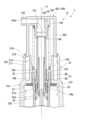
図1に示す吐出容器1は、有底筒状の容器本体11と、容器本体11の口部11aに着脱可能に装着された吐出器12と、を備えている。
容器本体11は、内容物が収容可能に構成されている。なお、内容物は、例えばシャンプーやボディソープ、化粧料等の液体である。(First embodiment)
The
The
吐出器12は、ポンプ機構14と、装着キャップ15と、吐出ヘッド16と、を備えている。ポンプ機構14は、ステム21やピストン22、シリンダ23、弁体24等を備えている。なお、ポンプ機構14のうち、少なくともステム21やピストン22、シリンダ23は、共通軸上に同軸に配設された筒状に形成されている。以下、共通軸を軸線Oといい、軸線Oに沿う方向を上下方向という。上下方向のうち、容器本体11の底部から吐出器12に向かう方向を上方とし、吐出器12から容器本体11の底部に向かう方向を下方とする。また、上下方向から見た平面視において、軸線Oに交差する方向を径方向といい、軸線O回りに周回する方向を周方向という。 The
シリンダ23は、上方に位置するものほど外径が拡大する多段筒状に形成されている。具体的に、シリンダ23は、取付筒31、弁座部32、収容筒33、摺動筒34及び突出筒35が下方から上方に連なっている。
取付筒31には、吸上筒40が嵌合されている。吸上筒40は、下端開口が容器本体11の底部に近接する位置まで延在している。
弁座部32は、取付筒31の上端開口縁から上方に向かうに従い漸次拡径するテーパ状に形成されている。
収容筒33は、弁座部32の上端開口縁から上方に延在している。
摺動筒34は、収容筒33の上端開口縁から上方に延在している。摺動筒34の上部には、摺動筒34を径方向に貫通する導入孔34aが形成されている。The
A
The
The
The
弁体24は、シリンダ23内を上下動可能に構成されている。具体的に、弁体24は、弁部41と、連結棒42と、を備えている。 The
弁部41は、シリンダ23内のうち、弁座部32から収容筒33に至る部分に収容されている。弁部41の下端は、弁体24の上下動に伴い、弁座部32の内面に接離可能に構成されている。すなわち、弁部41は、シリンダ23内の加圧時に弁座部32の下端開口を閉塞して、シリンダ23内と容器本体11内との連通を遮断する。一方、弁部41は、シリンダ23内の減圧時に弁座部32の内面から離間して、シリンダ23内と容器本体11内とを連通させる。なお、弁部41の外周面とシリンダ23の内周面とには、シリンダ23に対する弁体24の軸線O回りの回転を規制する回り止め部が形成されている。また、収容筒33内において、弁部41の周囲に位置する部分には、弁体24の上方移動を規制する弁押さえ部材43が嵌合されている。 The
連結棒42は、弁部41から上方に延在している。連結棒42は、摺動筒34内において軸線Oと同軸に配置されている。 The connecting
ステム21は、シリンダ23の摺動筒34内にシリンダ23の上方から挿入されている。ステム21は、吐出器12が容器本体11に装着された状態において、口部11aの内側に配設される。ステム21は、シリンダ23内において、後述する付勢部材150により上方付勢状態で下方移動可能に構成されている。本実施形態のステム21は、下ステム45と、上ステム46と、を備えている。 The
下ステム45は、嵌合筒51と、スカート部52と、を備えている。
嵌合筒51は、軸線Oと同軸に配置されている。嵌合筒51内には、上述した連結棒42が上下方向に摺動可能に嵌合されている。嵌合筒51には、嵌合筒51の内外を径方向に連通させる連通孔51aが形成されている。
スカート部52は、嵌合筒51の下端部から径方向の外側に張り出している。スカート部52は、下方に向かうに従い漸次拡径するテーパ状に形成されている。スカート部52の下端縁は、シリンダ23の内周面に当接している。スカート部52には、スカート部52を径方向に貫通する進入孔52aが形成されている。The
The
The
上ステム46は、内径が下ステム45の外径よりも大きい筒状に形成されている。上ステム46内には、上ステム46の下方から嵌合筒51が嵌合されている。 The
ピストン22は、外筒及び内筒が径方向に連結された構成である。
外筒は、上下方向の中央部から両側に向かうに従い外径が拡大している。外筒は、上下方向の両端部が摺動筒34の内周面上を上下方向に摺動可能に構成されている。
内筒は、下ステム45の外周面上を上下方向に摺動可能に構成されている。The
The outer diameter of the outer cylinder increases from the center in the vertical direction toward both sides. The outer tube is configured such that both ends thereof in the vertical direction can slide on the inner peripheral surface of the sliding
The inner cylinder is configured to be slidable in the vertical direction on the outer peripheral surface of the
ピストン22は、ステム21の上昇端位置において、外筒によって上述した導入孔34aを閉塞する。具体的に、外筒の上下方向の両端部が、摺動筒34の内周面のうち導入孔34aに対して上下方向の両側に位置する部分に密接することで、導入孔34aが閉塞される。 At the ascending end position of the
装着キャップ15は、ポンプ機構14が固定された状態で、容器本体11の口部11aに着脱可能に装着される。装着キャップ15は、容器取付部101と、ヘッドガイド102と、下ばね支持部103と、ポンプ保持部104と、を備えている。
容器取付部101は、有頂筒状に形成されている。容器取付部101の周壁部105は、口部11aに着脱可能に螺着される。但し、容器取付部101は、例えばアンダーカット嵌合等、螺着以外の方法によって口部11aに装着されていてもよい。The mounting
The
容器取付部101の頂壁部106は、周壁部105の上端縁から径方向の内側に張り出す環状に形成されている。頂壁部106は、容器取付部101が口部11aに装着された状態において、パッキン107を間に挟んで口部11aの上端縁上に配置される。 The
ヘッドガイド102は、内ガイド筒(ガイド筒)110及び外ガイド筒(ガイド筒)111を備える二重筒状に形成されている。但し、ヘッドガイド102は、内ガイド筒110及び外ガイド筒111の何れかのみを有する構成であってもよい。
内ガイド筒110は、頂壁部106の内周縁から上方に延在している。The
The
外ガイド筒111は、頂壁部106の外周縁から上方に延在している。外ガイド筒111は、内ガイド筒110の周囲を取り囲んでいる。外ガイド筒111は、内ガイド筒110よりも上方に突出している。外ガイド筒111には、径方向の外側に窪むとともに、上下方向に延びる規制溝(回り止め部)115が形成されている。規制溝115は、外ガイド筒111において、上下方向の全体に亘って形成されている。但し、規制溝115は、少なくとも外ガイド筒111の上端縁で開口していればよい。本実施形態において、規制溝115は、周方向で間隔をあけて複数(例えば、2つ)形成されている。 The
外ガイド筒111の上端部において、規制溝115以外の部分には、被係合部116が形成されている。被係合部116は、外ガイド筒111の内周面から径方向の内側に突出するとともに、周方向に延在している。なお、被係合部116の形状や周方向の形成範囲等は、適宜変更が可能である。 At the upper end of the
下ばね支持部103は、内ガイド筒110における上下方向の中間部から径方向の内側に突出する環状に形成されている。上述した内ガイド筒110のうち、下ばね支持部103よりも上方に位置する部分は、上方に向かうに従い内径が漸次拡大している。なお、下ばね支持部103は、周方向に間欠的に設けられていてもよい。 The lower
ポンプ保持部104は、下ばね支持部103の内周縁から下方に延在する筒状に形成されている。ポンプ保持部104は、上述した突出筒35内に嵌合されている。これにより、シリンダ23は、ポンプ保持部104と内ガイド筒110との間に突出筒35が保持された状態で、装着キャップ15から下方に延在している。 The
吐出ヘッド16は、下ヘッド120と、上ヘッド121と、を備えている。
下ヘッド120は、上方に位置するものほど縮径された多段筒状に形成されている。具体的に、下ヘッド120は、下筒部124と、接続フランジ125と、上筒部126と、を備えている。The
The
下筒部124は、軸線Oと同軸に配置されている。下筒部124は、内ガイド筒110及び外ガイド筒111の間に挿入され、内ガイド筒110及び外ガイド筒111の少なくとも一方に上下動可能に支持されている。ステム21が上昇端位置にあるとき、下筒部124の下部は、外ガイド筒111に取り囲まれている。 The
下筒部124の下端部には、径方向の外側に突出する係合部130が形成されている。本実施形態において、係合部130は、下筒部124の全周に亘って形成されている。係合部130は、上述した被係合部116に対して被係合部116の下方から係合可能に構成されている。吐出ヘッド16は、ステム21が上昇端位置にあるとき、装着キャップ15に対する上方移動が規制される。 An engaging
係合部130のうち、上述した規制溝115に径方向で対向する部分には、規制突起(回り止め部)131が形成されている。規制突起131は、上述した規制溝115内に収容されている。これにより、吐出ヘッド16は、装着キャップ15に対する軸線O回りの回転が規制されている。なお、下ヘッド120に規制溝を設け、装着キャップ15に規制突起を設ける構成であってもよい。また、規制溝や規制突起は必須の構成ではない。 A regulating protrusion (rotation stopper) 131 is formed in a portion of the engaging
接続フランジ125は、下筒部124の上端縁から径方向の内側に突出している。
上筒部126は、接続フランジ125の内周縁から上方に突出している。上筒部126の外周面には、雄ねじ部が形成されている。The
The
上ヘッド121は、ステム21(上ステム46)及び下ヘッド120に着脱可能に構成されている。上ヘッド121は、操作部140と、連結筒141と、上ばね支持部142と、吐出筒143と、を備えている。
操作部140は、有頂筒状に形成されている。操作部140において、周壁部144の下部内周面には、雌ねじ部が形成されている。周壁部144は、上述した上筒部126に螺着されている。周壁部144の雌ねじ部と、上筒部126の雄ねじ部と、は下ヘッド120に対して上ヘッド121が離脱可能に取り付けられる接続機構を構成している。本実施形態において、下ヘッド120及び上ヘッド121間の締結方向と、装着キャップ15及び容器本体11間の締結方向と、は逆ねじの関係になっていることが好ましい。但し、周壁部144は、例えばアンダーカット嵌合や爪による係止等、螺着以外の方法によって上筒部126に装着されていてもよい。The
The operating
連結筒141は、操作部140の天板部145から下方に延在している。連結筒141は、軸線Oと同軸に配置されている。連結筒141の上部には、径方向の内側に突出するリブ146が形成されている。リブ146は、連結筒141の上端縁から中間部分に至る範囲を上下方向に延在している。連結筒141内の下部には、上ステム46の上端部が着脱可能に嵌合されている。連結筒141の下部内周面には、嵌合突部147が形成されている。嵌合突部147は、連結筒141の内周面から径方向の内側に突出している。嵌合突部147は、上ステム46の外周面に密接している。なお、嵌合突部147は、必須の構成ではない。 The connecting
上ばね支持部142は、連結筒141のうち、ステム21よりも上方に位置する部分から径方向の外側に突出するとともに、上下方向に沿って延在している。上ばね支持部142の上端は、操作部140の天板部145に連なっている。上ばね支持部142の下端部は、上ヘッド121が下ヘッド120に取り付けられた状態において、上筒部126内に進入している。本実施形態において、上ばね支持部142は、周方向に間隔をあけて形成されている。但し、上ばね支持部142は、付勢部材150の上端部を支持できる構成であればよい。この場合、上ばね支持部142は、例えば連結筒141の全周に亘って延在していてもよく、天板部145から離間していてもよい。 The upper
吐出筒143は、操作部140の周壁部144を貫いて、連結筒141に達するように径方向に延在している。吐出筒143における径方向の内側開口部は、連結筒141内に連通している。吐出筒143における径方向の外側開口部は、連結筒141及び吐出筒143を通じてステム21内に連通する吐出口143aを構成している。 The
ここで、本実施形態のポンプ機構14は、ステム21を上方に付勢する付勢部材150を備えている。付勢部材150は、例えばコイルスプリングである。付勢部材150は、廃棄の際に吐出器12における他の構成部材とは分別が必要な材料(例えば、金属材料)により構成されている。本実施形態において、他の構成部材は、樹脂材料により形成されている。なお、付勢部材150は、コイルスプリングに限られない。 Here, the
付勢部材150は、下ヘッド120の内側において、ステム21の周囲を取り囲んでいる。したがって、付勢部材150は、下ヘッド120によって視認不能に構成されている。付勢部材150の下端部は、上述した下ばね支持部103に支持されている。付勢部材150の上端部は、上ばね支持部142に支持されている。すなわち、付勢部材150は、装着キャップ15と吐出ヘッド16との間に介在して、吐出ヘッド16を介してステム21を上方に向けて付勢している。なお、本実施形態において、上述した上昇端位置とは、付勢部材150の付勢によって吐出ヘッド16が上昇した状態であって、係合部130が被係合部116に下方から近接又は当接した状態である。なお、本実施形態では、吐出ヘッド16が上昇端位置にあるときに、連結筒141及び上ステム46間の嵌合と、周壁部144及び上筒部126間の締結と、が解除されないように付勢部材150の付勢力が設定されている。 The biasing
次に、上述した吐出容器1による内容物の吐出方法について説明する。以下の説明では、シリンダ23内に内容物が収容された状態を初期状態として説明する。
初期状態の吐出容器1から内容物を吐出するには、吐出ヘッド16を押下して、ステム21及び弁体24をシリンダ23に対して下方移動させる。すると、まず弁体24の弁部41が弁座部32の内面に当接し、弁座部32の下端開口が閉塞される。吐出ヘッド16をさらに下方に押し込むと、嵌合筒51の下端開口縁が連結棒42の外周面上を摺動することで、ステム21が弁体24に対して下方移動する。
一方、ステム21の下方移動に伴い、嵌合筒51の外周面上をピストン22が摺動することで、連通孔51aが開放されるとともに、上ステム46の下端縁がピストン22に当接する。Next, a method for discharging the contents using the discharging
To discharge the contents from the
On the other hand, as the
この状態において、吐出ヘッド16をさらに下方に押し込むと、ステム21とピストン22が一体となってシリンダ23内を下方移動する。これにより、シリンダ23内がピストン22によって加圧され、シリンダ23内の内容物が進入孔52a及び連通孔51aを通じてステム21内に流入する。その結果、ステム21内の内容物が吐出筒143内を通って、吐出口143aから吐出される。 In this state, when the
次に、吐出ヘッド16の押下を解除すると、付勢部材150の上方付勢力によって、吐出ヘッド16が押し上げられる。これにより、ステム21がピストン22及び弁体24に対して上昇することで、ピストン22によって連通孔51aが閉塞される。その後、ステム21、ピストン22及び弁体24が一体となって上昇することで、シリンダ23内が減圧される。これにより、シリンダ23(収容筒33)の下端開口が開放され、容器本体11内の内容物が、吸上筒40を通してシリンダ23内に流入する。 Next, when the depression of the
次に、吐出器12の廃棄方法(分解方法)について説明する。なお、吐出器12の分解作業は、容器本体11に装着された状態で行っても、容器本体11から取り外した状態で行ってもよい。
吐出器12を廃棄するにあたっては、図2に示すように、上ヘッド121を上ステム46及び下ヘッド120から取り外す。具体的には、下ヘッド120に対して上ヘッド121を軸線O回りの締結解除方向(軸線O回りの一方)に回転させる。この際、下ヘッド120は、装着キャップ15に対する回転が規制されているため、装着キャップ15又は下ヘッド120を把持した状態で、上ヘッド121を下ヘッド120に対して回転させることができる。これにより、下ヘッド120と上ヘッド121との螺着が解除される。なお、下ヘッド120と上ヘッド121との螺着が解除されると、下ヘッド120は規制突起131が規制溝115内に案内されながら、装着キャップ15に対して下方移動する。Next, a method of disposing (disassembling) the
When discarding the
下ヘッド120と上ヘッド121との螺着が解除される過程において、上ヘッド121は締結解除方向に回転しながら上昇する。この際、上ヘッド121が上ステム46に対して上昇することで、上ヘッド121と上ステム46との嵌合も解除される。
その結果、上ヘッド121が上ステム46及び下ヘッド120から取り外される。すなわち、上ヘッド121は、ステム21及びヘッドガイド102から離脱する。In the process of releasing the screw connection between the
As a result, the
上ヘッド121が上ステム46及び下ヘッド120に対して取り外されることで、下ヘッド120の上端開口が開放されるとともに、上ばね支持部142による付勢部材150の上端部の支持が解除される。なお、付勢部材150は、自然長の状態で、下ヘッド120よりも上方に突出する長さに設定されている。 By removing the
続いて、付勢部材150を上方に引き上げることで、付勢部材150がステム21の周囲から取り外される。これにより、吐出器12の構成部材の中から、分別が必要な付勢部材150を取り外すことができる。その後、付勢部材150と、他の構成部材と、を分別して廃棄する。 Subsequently, the biasing
このように、本実施形態では、上ばね支持部142が、ヘッドガイド102及びステム21に対する締結解除方向への回転により、ヘッドガイド102及びステム21から離脱可能な構成とした。
この構成によれば、上ばね支持部142をヘッドガイド102及びステム21から取り外すことで、上ばね支持部112による付勢部材150の上端部の支持が解除される。これにより、吐出器12の構成部材の中から、付勢部材150を取り出すことができる。そのため、付勢部材150を廃棄時に簡単に取り外すことができ、付勢部材150と、その他の構成部材と、を分別することができる。その結果、環境負荷の低減化、廃棄物の処理効率の向上化等に対応することができる。
特に、本実施形態では、付勢部材150が装着キャップ15と吐出ヘッド16との間に介在しているので、吐出器12の使用時や分解時等において、付勢部材150が内容物に浸漬等するのを抑制できる。これにより、分解時に内容物が手に付着したり、付勢部材150を分解後に洗浄したりする等の手間が軽減される。As described above, in this embodiment, the upper
According to this configuration, by removing the
In particular, in this embodiment, since the biasing
本実施形態では、吐出ヘッド16が、下ヘッド120と、下ヘッド120に対して離脱可能な上ヘッド121と、を備え、下ヘッド120と外ガイド筒111との間には、外ガイド筒111に対する下ヘッド120の回転を規制する回り止め部(規制溝115及び規制突起131)が配設される構成とした。
この構成によれば、上ヘッド121のみを離脱可能とすることで、下ヘッド120と外ガイド筒111との間に回り止め部を配設でき、吐出操作の際に吐出ヘッド16の上下動をスムーズに行うことができる。
また、分解される構成部品を小さくすることができるので、廃棄時に嵩張ること等を抑制できる。In this embodiment, the
According to this configuration, by making only the
Furthermore, since the component parts to be disassembled can be made smaller, it is possible to suppress bulkiness when discarding the product.
本実施形態において、下ヘッド120及び上ヘッド121間の締結方向と、装着キャップ15及び容器本体11間の締結方向と、は逆ねじの関係になっている構成とした。
この構成によれば、上ヘッド121の回転につられて装着キャップ15が回転したとしても、上ヘッド121と装着キャップ15とが共に緩んだり、締め付けられたりするのを抑制できる。これにより、上ヘッド121や装着キャップ15の双方が予期せず緩んだり、締め付けられたりするのを抑制できる。この場合、例えば容器本体11に吐出器12を装着した状態で、容器本体11を把持して上ヘッド121を取り外し方向に回転させることで、容器本体11と装着キャップ15とは締め付け方向へ回転する。そのため、装着キャップ15を容器本体11から離脱させないまま、上ヘッド121を取り外すことができる。In this embodiment, the fastening direction between the
According to this configuration, even if the mounting
(第2実施形態)
本実施形態では、装着キャップ15やステム21に対して吐出ヘッド201全体が離脱可能な点で上述した実施形態と相違している。
図3に示すように、吐出ヘッド201は、有頂筒状に形成されている。吐出ヘッド201において、周壁部202の下端部には、係合部210が形成されている。係合部210は、周壁部202から径方向の外側に向けて突出している。係合部210は、周方向に間隔をあけて複数形成されている。(Second embodiment)
This embodiment differs from the above-described embodiments in that the
As shown in FIG. 3, the
外ガイド筒111の上端部には、被係合部215が形成されている。被係合部215の下端縁には、吐出ヘッド201が上昇端位置にあるとき、係合部210が被係合部215の下方から近接又は当接する。これにより、ステム21が上昇端位置にあるとき、装着キャップ15に対する吐出ヘッド201の上方移動が規制される。本実施形態において、被係合部215は二条ねじである。但し、被係合部215は、二条ねじ以外の多条ねじであってもよく、一条ねじであってもよい。本実施形態においても、係合部210及び被係合部215間と、装着キャップ15及び容器本体11間と、は逆ねじの関係になっていることが好ましい。 An engaged
本実施形態において、付勢部材150を取り外すには、ステム21及び装着キャップ15から吐出ヘッド201全体を取り外す。具体的には、装着キャップ15に対して吐出ヘッド201を締結解除方向に回転させる。すると、図4に示すように、吐出ヘッド201は、締結解除方向への回転に伴い上昇することで、ステム21及び装着キャップ15から取り外される。これにより、上ばね支持部142による付勢部材150の上端部の支持が解除される。すなわち、本実施形態では、係合部210及び被係合部215自体が接続機構を構成している。その後、付勢部材150を取り除くことで、付勢部材150と、他の構成部材と、を分別して廃棄することができる。 In this embodiment, in order to remove the biasing
本実施形態によれば、吐出ヘッド201が一体に形成されているので、部品点数の削減を図ることができる。
しかも、本実施形態では、被係合部215が二条ねじにより形成されているため、一条ねじである構成と比較して、ねじのリードが大きくなる。このため、吐出ヘッド201の回転量に対する上下方向の変位量を大きくすることができる。これにより、吐出ヘッド201を速やかに上昇させ、吐出ヘッド201を装着キャップ15から速やかに離脱させることができる。According to this embodiment, since the
Furthermore, in this embodiment, since the engaged
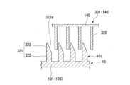
(第3実施形態)
本実施形態では、吐出ヘッド301と装着キャップ15との接続機構が、上述した第2実施形態と相違している。
図5に示すように、吐出ヘッド301は、有頂筒状に形成されている。吐出ヘッド301において、周壁部302の下端部には、係合部310が形成されている。係合部310は、径方向の外側に向けて突出している。係合部310は、例えば周壁部302の全周に亘って延在している。係合部310は、外ガイド筒111の上端部に形成された被係合部311に被係合部311の下方から近接又は当接している。これにより、ステム21が上昇端位置にあるとき、装着キャップ15に対する吐出ヘッド301の上方移動が規制される。(Third embodiment)
In this embodiment, the connection mechanism between the
As shown in FIG. 5, the
図5、図6に示すように、吐出ヘッド301の周壁部302には、径方向の内側に突出する摺動片320が形成されている。摺動片320は、上下方向において、周壁部の全長に亘って延在している。すなわち、摺動片320の上端縁は、吐出ヘッド301の天板部303に接続されている。一方、摺動片320の下端縁は、周壁部302の下端縁と面一に配置されている。摺動片320の下端縁は、上下方向に直交する平坦面に形成されている。本実施形態において、摺動片320は、周方向に間隔をあけて複数形成されている。なお、摺動片320の長さや数等は、適宜変更が可能である。 As shown in FIGS. 5 and 6, a sliding
内ガイド筒110には、径方向の外側に突出するガイド壁321が形成されている。ガイド壁321は、上下方向において、内ガイド筒110の全長に亘って延在している。ガイド壁321は、周方向に間隔をあけて複数形成されている。周方向で隣り合うガイド壁321同士の間には、上述した摺動片320が各別に配置されている。ガイド壁321は、内ガイド筒110の下部に位置する直線部322と、内ガイド筒110の上部に位置するテーパ部323と、を備えている。 The
直線部322は、内ガイド筒110の下端から中間部分に至る範囲を上下方向に沿って直線状に延在している。
テーパ部323は、直線部322から上方に連なっている。テーパ部323のうち、周方向の一方を向く面は、直線部322と面一に配置されている。テーパ部323のうち、周方向の他方を向く面は、上方に向かうに従い周方向の一方に向けて延びる傾斜面323aになっている。The
The tapered
本実施形態の吐出器12は、吐出ヘッド301が上昇端位置にあるとき、摺動片320の下部がテーパ部323と周方向で対向している。この状態で、付勢部材150を取り外すには、装着キャップ15に対して吐出ヘッド301を周方向の一方に向けて回転させる。すると、図7、図8に示すように、摺動片320の下端縁が傾斜面323aに接触する。この状態で、吐出ヘッド301をさらに周方向の一方に回転させると、摺動片320の下端縁が傾斜面323a上を摺動する。これにより、吐出ヘッド301は、周方向の一方への回転に伴い、上方へ案内される。その結果、係合部310が被係合部311を上方に乗り越え、吐出ヘッド301が装着キャップ15(ヘッドガイド102)から取り外される。また、吐出ヘッド301の上昇に伴い、吐出ヘッド301と上ステム46との嵌合も解除される。すなわち、本実施形態では、摺動片320及びガイド壁321が、係合部310及び被係合部311とは別体の接続機構を構成している。その後、付勢部材150を取り外すことで、付勢部材150と、他の構成部材と、を分別して廃棄することができる。本実施形態においても、摺動片320及びテーパ部323間と、装着キャップ15及び容器本体11間と、は逆ねじの関係になっていることが好ましい。すなわち、装着キャップ15に対する吐出ヘッド301の回転方向のうち、摺動片320がテーパ部323の傾斜面323上を上方に向けて摺動する方向が、装着キャップ15が容器本体11に締め付けられる方向に一致している。 In the
本実施形態によれば、係合部310と摺動片320とを別々に設けることで、設計自由度の向上を図ることができる。 According to this embodiment, by providing the engaging
以上、本発明の好ましい実施形態を説明したが、本発明はこれら実施形態に限定されることはない。本発明の趣旨を逸脱しない範囲で、構成の付加、省略、置換及びその他の変更が可能である。本発明は上述した説明によって限定されることはなく、添付の特許請求の範囲によってのみ限定される。
例えば、上述した実施形態では、付勢部材150の上端部が天板部145から延びる上ばね支持部142に支持された構成について説明したが、この構成に限られない。上ばね支持部は、例えば天板部145自体や連結筒141等、吐出ヘッド16の任意の位置に設定することが可能である。
上述した実施形態では、下ばね支持部103が装着キャップ15に一体に設けられた構成について説明したが、この構成に限られない。下ばね支持部103は、シリンダ23や装着キャップ15に別体で設けられていてもよく、シリンダ23と一体で設けられていてもよい。Although preferred embodiments of the present invention have been described above, the present invention is not limited to these embodiments. Additions, omissions, substitutions, and other changes to the structure are possible without departing from the spirit of the present invention. The invention is not limited by the above description, but only by the scope of the claims appended hereto.
For example, in the embodiment described above, the upper end of the biasing
In the embodiment described above, a configuration in which the lower
上述した実施形態では、ヘッドガイド102が装着キャップ15に一体で形成された構成について説明したが、この構成に限られない。ヘッドガイド102は、容器本体11に取り付けられる構成であれば、装着キャップ15と別体であってもよい。 In the embodiment described above, the configuration in which the
その他、本発明の趣旨を逸脱しない範囲で、上記した実施の形態における構成要素を周知の構成要素に置き換えることは適宜可能であり、また、上記した変形例を適宜組み合わせてもよい。 In addition, without departing from the spirit of the present invention, the components in the embodiments described above can be replaced with well-known components as appropriate, and the modifications described above may be combined as appropriate.
11…容器本体
11a…口部
12…吐出器
15…装着キャップ
16…吐出ヘッド
21…ステム
22…ピストン
23…シリンダ
110…内ガイド筒(ガイド筒)
111…外ガイド筒(ガイド筒)
115…規制溝(回り止め部)
116…被係合部
120…下ヘッド
121…上ヘッド
130…係合部
131…規制突起(回り止め部)
150…付勢部材
201…吐出ヘッド
210…係合部
215…被係合部
301…吐出ヘッド
310…係合部
311…被係合部11...
111...Outer guide tube (guide tube)
115...Regulation groove (rotation prevention part)
116...
150...
Claims (4)
Translated fromJapanese前記ステムが挿入された筒状のシリンダと、
前記シリンダの内側で前記ステムの上下動に連係するとともに、前記シリンダの内周面に上下摺動可能に嵌合されたピストンと、
前記ステムの上端部に着脱可能に取り付けられ、内容物を吐出する吐出口を有する吐出ヘッドと、
前記ステムの周囲に配置されるとともに、前記吐出ヘッドを介して前記ステムを上方付勢する付勢部材と、
前記容器本体に取り付けられるとともに、前記付勢部材の周囲に配置され、前記吐出ヘッドの上下動を案内するガイド筒と、を備え、
前記吐出ヘッドは、
前記付勢部材の上端部を支持する上ばね支持部と、
前記吐出ヘッドが上昇端位置にあるとき、前記ガイド筒に形成された被係合部に下方から係合して前記ガイド筒に対する前記吐出ヘッドの上方移動を規制する係合部と、を備え、
前記上ばね支持部は、前記ガイド筒及び前記ステムに対する前記ガイド筒の軸線回りの一方への回転操作のみにより、前記ガイド筒及び前記ステムから離脱可能に構成されている吐出器。a stem disposed inside the mouth of the container body so as to be movable downward in an upwardly biased state;
a cylindrical cylinder into which the stem is inserted;
a piston that is connected to the vertical movement of the stem inside the cylinder and is fitted to the inner circumferential surface of the cylinder so as to be vertically slidable;
a discharge head that is detachably attached to the upper end of the stem and has a discharge port for discharging the contents;
a biasing member disposed around the stem and biasing the stem upward via the ejection head;
a guide cylinder that is attached to the container main body, is arranged around the biasing member, and guides vertical movement of the ejection head;
The ejection head is
an upper spring supporter that supports the upper end of the biasing member;
an engaging portion that engages from below with an engaged portion formed on the guide cylinder to restrict upward movement of the ejection head with respect to the guide cylinder when the ejection head is at a rising end position;
The upper spring support portion is configured to be detachable from the guide tube and the stemonly by rotating the guide tube and the stem in one direction around the axis of the guide tube.
前記ステムが挿入された筒状のシリンダと、
前記シリンダの内側で前記ステムの上下動に連係するとともに、前記シリンダの内周面に上下摺動可能に嵌合されたピストンと、
前記ステムの上端部に着脱可能に取り付けられ、内容物を吐出する吐出口を有する吐出ヘッドと、
前記ステムの周囲に配置されるとともに、前記吐出ヘッドを介して前記ステムを上方付勢する付勢部材と、
前記容器本体に取り付けられるとともに、前記付勢部材の周囲に配置され、前記吐出ヘッドの上下動を案内するガイド筒と、を備え、
前記吐出ヘッドは、
前記付勢部材の上端部を支持する上ばね支持部と、
前記吐出ヘッドが上昇端位置にあるとき、前記ガイド筒に形成された被係合部に下方から係合して前記ガイド筒に対する前記吐出ヘッドの上方移動を規制する係合部と、
前記係合部を有し、前記ガイド筒に上下動可能に支持された下ヘッドと、
前記上ばね支持部を有し、前記下ヘッドに取り付けられる上ヘッドと、を備え、
前記下ヘッドと前記ガイド筒との間には、前記ガイド筒に対する前記下ヘッドの軸線回りの回転を規制する回り止め部が配設され、
前記上ヘッドは、前記下ヘッドに対する軸線回りの一方への回転操作に伴い前記下ヘッドから離脱可能に構成されている記載の吐出器。a stem disposed inside the mouth of the container body so as to be movable downward in an upwardly biased state;
a cylindrical cylinder into which the stem is inserted;
a piston that is connected to the vertical movement of the stem inside the cylinder and is fitted to the inner circumferential surface of the cylinder so as to be vertically slidable;
a discharge head that is detachably attached to the upper end of the stem and has a discharge port for discharging the contents;
a biasing member disposed around the stem and biasing the stem upward via the ejection head;
a guide cylinder that is attached to the container main body, is arranged around the biasing member, and guides vertical movement of the ejection head;
The ejection head is
an upper spring supporter that supports the upper end of the biasing member;
an engaging portion that engages from below with an engaged portion formed on the guide cylinder to restrict upward movement of the ejection head with respect to the guide cylinder when the ejection head is at a rising end position;
a lower head having the engaging portion and supported by the guide cylinder so as to be movable up and down;
an upper head having the upper spring support part and attached to the lower head;
A rotation stopper is disposed between the lower head and the guide cylinder, and the rotation stopper restricts rotation of the lower head about the axis with respect to the guide cylinder,
The ejector according to claim 1, wherein the upper head is configured to be detachable from the lower head when the lower head is rotated in one direction aroundan axis .
前記吐出ヘッドは、前記ガイド筒及び前記ステムに対する前記ガイド筒の軸線回りの一方への回転操作により、前記係合部と前記被係合部との係合が解除されることで、前記ガイド筒及び前記ステムから離脱可能に構成されている請求項1に記載の吐出器。The upper spring support part and the engagement part are integrally formed,
The ejection head is configured to rotate the guide tube and the stem by rotating the guide tube in one direction around the axis of the guide tube to disengage the engaging portion and the engaged portion. The ejector according to claim 1, wherein the ejector is configured to be detachable from the stem.
Priority Applications (1)
| Application Number | Priority Date | Filing Date | Title |
|---|---|---|---|
| JP2019216959AJP7357523B2 (en) | 2019-11-29 | 2019-11-29 | Dispenser |
Applications Claiming Priority (1)
| Application Number | Priority Date | Filing Date | Title |
|---|---|---|---|
| JP2019216959AJP7357523B2 (en) | 2019-11-29 | 2019-11-29 | Dispenser |
Publications (2)
| Publication Number | Publication Date |
|---|---|
| JP2021084691A JP2021084691A (en) | 2021-06-03 |
| JP7357523B2true JP7357523B2 (en) | 2023-10-06 |
Family
ID=76086992
Family Applications (1)
| Application Number | Title | Priority Date | Filing Date |
|---|---|---|---|
| JP2019216959AActiveJP7357523B2 (en) | 2019-11-29 | 2019-11-29 | Dispenser |
Country Status (1)
| Country | Link |
|---|---|
| JP (1) | JP7357523B2 (en) |
Citations (2)
| Publication number | Priority date | Publication date | Assignee | Title |
|---|---|---|---|---|
| JP2002224602A (en) | 2001-01-31 | 2002-08-13 | Yoshino Kogyosho Co Ltd | Liquid discharge vessel |
| JP2003033686A (en) | 2001-07-25 | 2003-02-04 | Yoshino Kogyosho Co Ltd | Accumulator spray vessel |
Family Cites Families (2)
| Publication number | Priority date | Publication date | Assignee | Title |
|---|---|---|---|---|
| US5105988A (en)* | 1990-06-15 | 1992-04-21 | Calmar Inc. | Protector cap and wiper for dispenser discharge orifice |
| JP2509241Y2 (en)* | 1990-07-26 | 1996-08-28 | 株式会社吉野工業所 | Creamy object discharge container |
- 2019
- 2019-11-29JPJP2019216959Apatent/JP7357523B2/enactiveActive
Patent Citations (2)
| Publication number | Priority date | Publication date | Assignee | Title |
|---|---|---|---|---|
| JP2002224602A (en) | 2001-01-31 | 2002-08-13 | Yoshino Kogyosho Co Ltd | Liquid discharge vessel |
| JP2003033686A (en) | 2001-07-25 | 2003-02-04 | Yoshino Kogyosho Co Ltd | Accumulator spray vessel |
Also Published As
| Publication number | Publication date |
|---|---|
| JP2021084691A (en) | 2021-06-03 |
Similar Documents
| Publication | Publication Date | Title |
|---|---|---|
| EP3735323B1 (en) | Dispensing pump with locking structures and methods of using the same | |
| EP3209428B1 (en) | Pump dispensers | |
| CN1067958C (en) | push dispenser | |
| EP3656695B1 (en) | Lotion pump | |
| KR20040014298A (en) | Pump dispenser having an improved discharge valve | |
| JP4829319B2 (en) | Aircraft filter apparatus having cartridge locking and driving member | |
| JP7357523B2 (en) | Dispenser | |
| KR102385651B1 (en) | Cosmetic container for easy replacement | |
| JP7378319B2 (en) | Dispenser | |
| JP7308735B2 (en) | ejector | |
| JP7218063B2 (en) | discharge container | |
| JP7292199B2 (en) | ejector | |
| JP7462405B2 (en) | Discharger | |
| JP2021008283A (en) | Pump mechanism | |
| JP7365965B2 (en) | Discharge container | |
| JP2023125551A (en) | Discharger | |
| JP6634355B2 (en) | Discharge container | |
| JP7386721B2 (en) | Dispenser | |
| JP2021160766A (en) | Discharge tool | |
| JP6101612B2 (en) | Discharge container | |
| JP2020147326A (en) | Discharger | |
| JP7357589B2 (en) | Dispenser | |
| JP2011213390A (en) | Dispensing pump | |
| JP6910265B2 (en) | Metering dispenser | |
| KR102686477B1 (en) | Refill Type Cosmetic Container |
Legal Events
| Date | Code | Title | Description |
|---|---|---|---|
| A621 | Written request for application examination | Free format text:JAPANESE INTERMEDIATE CODE: A621 Effective date:20220602 | |
| A977 | Report on retrieval | Free format text:JAPANESE INTERMEDIATE CODE: A971007 Effective date:20230308 | |
| A131 | Notification of reasons for refusal | Free format text:JAPANESE INTERMEDIATE CODE: A131 Effective date:20230314 | |
| A521 | Request for written amendment filed | Free format text:JAPANESE INTERMEDIATE CODE: A523 Effective date:20230501 | |
| TRDD | Decision of grant or rejection written | ||
| A01 | Written decision to grant a patent or to grant a registration (utility model) | Free format text:JAPANESE INTERMEDIATE CODE: A01 Effective date:20230829 | |
| A61 | First payment of annual fees (during grant procedure) | Free format text:JAPANESE INTERMEDIATE CODE: A61 Effective date:20230926 | |
| R150 | Certificate of patent or registration of utility model | Ref document number:7357523 Country of ref document:JP Free format text:JAPANESE INTERMEDIATE CODE: R150 |