JP7354601B2 - In-vehicle network system - Google Patents
In-vehicle network systemDownload PDFInfo
- Publication number
- JP7354601B2 JP7354601B2JP2019108202AJP2019108202AJP7354601B2JP 7354601 B2JP7354601 B2JP 7354601B2JP 2019108202 AJP2019108202 AJP 2019108202AJP 2019108202 AJP2019108202 AJP 2019108202AJP 7354601 B2JP7354601 B2JP 7354601B2
- Authority
- JP
- Japan
- Prior art keywords
- communication
- vehicle
- sub
- processing unit
- main processing
- Prior art date
- Legal status (The legal status is an assumption and is not a legal conclusion. Google has not performed a legal analysis and makes no representation as to the accuracy of the status listed.)
- Active
Links
- 238000004891communicationMethods0.000claimsdescription225
- 238000004364calculation methodMethods0.000claimsdescription13
- 238000000034methodMethods0.000claimsdescription4
- 230000033001locomotionEffects0.000description16
- 238000012806monitoring deviceMethods0.000description16
- 230000006870functionEffects0.000description15
- 230000006399behaviorEffects0.000description13
- 238000010586diagramMethods0.000description8
- 238000005516engineering processMethods0.000description6
- 230000001133accelerationEffects0.000description3
- 238000013528artificial neural networkMethods0.000description3
- 238000003384imaging methodMethods0.000description3
- 230000005540biological transmissionEffects0.000description2
- 238000013527convolutional neural networkMethods0.000description2
- 238000013135deep learningMethods0.000description2
- 238000001514detection methodMethods0.000description2
- 230000008451emotionEffects0.000description2
- 230000036541healthEffects0.000description2
- 238000009434installationMethods0.000description2
- 230000002093peripheral effectEffects0.000description2
- 206010048909BoredomDiseases0.000description1
- 230000005856abnormalityEffects0.000description1
- 230000017531blood circulationEffects0.000description1
- 230000003247decreasing effectEffects0.000description1
- 239000000446fuelSubstances0.000description1
- 230000036449good healthEffects0.000description1
- 238000002347injectionMethods0.000description1
- 239000007924injectionSubstances0.000description1
- 230000007794irritationEffects0.000description1
- 238000011084recoveryMethods0.000description1
- 238000005096rolling processMethods0.000description1
- 238000009987spinningMethods0.000description1
- 210000004243sweatAnatomy0.000description1
Images


Classifications
- B—PERFORMING OPERATIONS; TRANSPORTING
- B60—VEHICLES IN GENERAL
- B60W—CONJOINT CONTROL OF VEHICLE SUB-UNITS OF DIFFERENT TYPE OR DIFFERENT FUNCTION; CONTROL SYSTEMS SPECIALLY ADAPTED FOR HYBRID VEHICLES; ROAD VEHICLE DRIVE CONTROL SYSTEMS FOR PURPOSES NOT RELATED TO THE CONTROL OF A PARTICULAR SUB-UNIT
- B60W50/00—Details of control systems for road vehicle drive control not related to the control of a particular sub-unit, e.g. process diagnostic or vehicle driver interfaces
- B60W50/02—Ensuring safety in case of control system failures, e.g. by diagnosing, circumventing or fixing failures
- B60W50/035—Bringing the control units into a predefined state, e.g. giving priority to particular actuators
- H—ELECTRICITY
- H04—ELECTRIC COMMUNICATION TECHNIQUE
- H04L—TRANSMISSION OF DIGITAL INFORMATION, e.g. TELEGRAPHIC COMMUNICATION
- H04L12/00—Data switching networks
- H04L12/28—Data switching networks characterised by path configuration, e.g. LAN [Local Area Networks] or WAN [Wide Area Networks]
- H04L12/40—Bus networks
- H04L12/40143—Bus networks involving priority mechanisms
- H04L12/40163—Bus networks involving priority mechanisms by assigning priority to messages according to a message field
- B—PERFORMING OPERATIONS; TRANSPORTING
- B60—VEHICLES IN GENERAL
- B60W—CONJOINT CONTROL OF VEHICLE SUB-UNITS OF DIFFERENT TYPE OR DIFFERENT FUNCTION; CONTROL SYSTEMS SPECIALLY ADAPTED FOR HYBRID VEHICLES; ROAD VEHICLE DRIVE CONTROL SYSTEMS FOR PURPOSES NOT RELATED TO THE CONTROL OF A PARTICULAR SUB-UNIT
- B60W10/00—Conjoint control of vehicle sub-units of different type or different function
- B60W10/04—Conjoint control of vehicle sub-units of different type or different function including control of propulsion units
- B—PERFORMING OPERATIONS; TRANSPORTING
- B60—VEHICLES IN GENERAL
- B60W—CONJOINT CONTROL OF VEHICLE SUB-UNITS OF DIFFERENT TYPE OR DIFFERENT FUNCTION; CONTROL SYSTEMS SPECIALLY ADAPTED FOR HYBRID VEHICLES; ROAD VEHICLE DRIVE CONTROL SYSTEMS FOR PURPOSES NOT RELATED TO THE CONTROL OF A PARTICULAR SUB-UNIT
- B60W10/00—Conjoint control of vehicle sub-units of different type or different function
- B60W10/18—Conjoint control of vehicle sub-units of different type or different function including control of braking systems
- B—PERFORMING OPERATIONS; TRANSPORTING
- B60—VEHICLES IN GENERAL
- B60W—CONJOINT CONTROL OF VEHICLE SUB-UNITS OF DIFFERENT TYPE OR DIFFERENT FUNCTION; CONTROL SYSTEMS SPECIALLY ADAPTED FOR HYBRID VEHICLES; ROAD VEHICLE DRIVE CONTROL SYSTEMS FOR PURPOSES NOT RELATED TO THE CONTROL OF A PARTICULAR SUB-UNIT
- B60W10/00—Conjoint control of vehicle sub-units of different type or different function
- B60W10/20—Conjoint control of vehicle sub-units of different type or different function including control of steering systems
- B—PERFORMING OPERATIONS; TRANSPORTING
- B60—VEHICLES IN GENERAL
- B60W—CONJOINT CONTROL OF VEHICLE SUB-UNITS OF DIFFERENT TYPE OR DIFFERENT FUNCTION; CONTROL SYSTEMS SPECIALLY ADAPTED FOR HYBRID VEHICLES; ROAD VEHICLE DRIVE CONTROL SYSTEMS FOR PURPOSES NOT RELATED TO THE CONTROL OF A PARTICULAR SUB-UNIT
- B60W30/00—Purposes of road vehicle drive control systems not related to the control of a particular sub-unit, e.g. of systems using conjoint control of vehicle sub-units
- B60W30/14—Adaptive cruise control
- H—ELECTRICITY
- H04—ELECTRIC COMMUNICATION TECHNIQUE
- H04L—TRANSMISSION OF DIGITAL INFORMATION, e.g. TELEGRAPHIC COMMUNICATION
- H04L12/00—Data switching networks
- H04L12/28—Data switching networks characterised by path configuration, e.g. LAN [Local Area Networks] or WAN [Wide Area Networks]
- H04L12/40—Bus networks
- H04L12/40169—Flexible bus arrangements
- H04L12/40176—Flexible bus arrangements involving redundancy
- H04L12/40182—Flexible bus arrangements involving redundancy by using a plurality of communication lines
- B—PERFORMING OPERATIONS; TRANSPORTING
- B60—VEHICLES IN GENERAL
- B60R—VEHICLES, VEHICLE FITTINGS, OR VEHICLE PARTS, NOT OTHERWISE PROVIDED FOR
- B60R16/00—Electric or fluid circuits specially adapted for vehicles and not otherwise provided for; Arrangement of elements of electric or fluid circuits specially adapted for vehicles and not otherwise provided for
- B60R16/02—Electric or fluid circuits specially adapted for vehicles and not otherwise provided for; Arrangement of elements of electric or fluid circuits specially adapted for vehicles and not otherwise provided for electric constitutive elements
- B60R16/023—Electric or fluid circuits specially adapted for vehicles and not otherwise provided for; Arrangement of elements of electric or fluid circuits specially adapted for vehicles and not otherwise provided for electric constitutive elements for transmission of signals between vehicle parts or subsystems
- H—ELECTRICITY
- H04—ELECTRIC COMMUNICATION TECHNIQUE
- H04L—TRANSMISSION OF DIGITAL INFORMATION, e.g. TELEGRAPHIC COMMUNICATION
- H04L12/00—Data switching networks
- H04L12/28—Data switching networks characterised by path configuration, e.g. LAN [Local Area Networks] or WAN [Wide Area Networks]
- H04L12/40—Bus networks
- H04L2012/40267—Bus for use in transportation systems
- H04L2012/40273—Bus for use in transportation systems the transportation system being a vehicle
Landscapes
- Engineering & Computer Science (AREA)
- Transportation (AREA)
- Mechanical Engineering (AREA)
- Combustion & Propulsion (AREA)
- Chemical & Material Sciences (AREA)
- Automation & Control Theory (AREA)
- Computer Networks & Wireless Communication (AREA)
- Signal Processing (AREA)
- Human Computer Interaction (AREA)
- Steering Control In Accordance With Driving Conditions (AREA)
- Control Of Driving Devices And Active Controlling Of Vehicle (AREA)
- Small-Scale Networks (AREA)
- Regulating Braking Force (AREA)
Description
Translated fromJapaneseここに開示された技術は、車載用のネットワークシステムに関する技術分野に属する。 The technology disclosed herein belongs to the technical field related to in-vehicle network systems.
特許文献1には、車載機器の機能に応じて複数のドメインに区分けし、ドメイン毎にドメイン制御部を設け、複数のドメイン制御部を統合制御部で制御する技術が開示されている。特許文献1では、例えば、各機器制御部が、単一または複数のECUで実現されており、それらのECUが階層型のネットワークにより接続されている。 Patent Document 1 discloses a technology in which in-vehicle equipment is divided into a plurality of domains according to the functions, a domain control unit is provided for each domain, and the plurality of domain control units are controlled by an integrated control unit. In Patent Document 1, for example, each device control unit is realized by a single or multiple ECUs, and these ECUs are connected by a hierarchical network.
一般的に、ネットワークシステムの一部に障害や異常が発生し、通信経路の一部が途絶する可能性があることが知られている。その場合に、特許文献1のような構成にした場合、統合制御部やドメイン制御部から車載機器を制御するECUへの通信が阻害される恐れがある。 It is generally known that a failure or abnormality may occur in a part of a network system, leading to the disruption of part of the communication path. In that case, if the configuration is as in Patent Document 1, there is a risk that communication from the integrated control unit or the domain control unit to the ECU that controls the on-vehicle equipment may be obstructed.
ここに開示された技術は、斯かる点に鑑みてなされたものであり、その目的とするとこは、車載ネットワークの一部が途絶した場合に主要機能が喪失されるのを防ぐことにある。 The technology disclosed herein has been developed in view of this point, and its purpose is to prevent loss of major functions when a portion of the in-vehicle network is interrupted.
前記課題を解決するために、ここに開示された技術では、車載ネットワークシステムを対象とし、当該車載ネットワークシステムは、主演算装置と、前記主演算装置から放射状に延びる複数の通信経路と、いずれかの前記通信経路を介して主演算装置に接続された複数の副演算装置とを備え、前記複数の副演算装置は、前記複数の通信経路を介して前記主演算装置に接続された少なくとも1つの第1副演算装置を含み、前記各通信経路では、通信種別に応じた優先順位があらかじめ設定され、前記主演算装置は、前記第1副演算装置と通信する前記通信経路の一部に途絶が確認された場合に、前記通信経路の残部において、前記優先順位が所定の基準よりも低い通信を減らし、当該減らした領域に前記途絶された通信経路での通信のうち前記優先順位が所定の基準よりも高い通信を割り当てる、という構成とした。 In order to solve the above problems, the technology disclosed herein targets an in-vehicle network system, and the in-vehicle network system includes either a main processing unit or a plurality of communication paths extending radially from the main processing unit. a plurality of sub-processing devices connected to the main processing device via the communication paths, and the plurality of sub-processing devices are connected to at least one main processing device via the plurality of communication paths. The main processing device includes a first sub-processing device, and each of the communication paths has a priority set in advance according to the type of communication, and the main processing device includes a first sub-processing device when a part of the communication path communicating with the first sub-processing device is interrupted. If confirmed, in the remaining part of the communication path, reduce the communication whose priority is lower than the predetermined standard, and in the reduced area, among the communications on the interrupted communication path, the communication whose priority is lower than the predetermined standard. The configuration was such that a higher communication rate was allocated.
この構成によると、主演算装置と第1副演算装置との間を、複数の通信経路を介して接続している。これにより、主演算装置と第1副演算装置とは、1つの通信経路が途絶した場合においても、他の通信経路を介して通信を継続することができる。また、一部の通信経路で途絶された場合に、途絶されていない通信経路(通信経路の残部)において、優先順位が所定の基準よりも低い通信を減らし、減らした領域に主演算装置と第1副演算装置との間で途絶された通信のうち優先順位が所定の基準よりも高い通信を割り当てている。これにより、優先順位が相対的に高い機能、いわゆる「主要機能」が喪失されるのを防ぐことができる。 According to this configuration, the main processing device and the first sub-processing device are connected via a plurality of communication paths. Thereby, even if one communication path is interrupted, the main processing device and the first sub-processing device can continue communicating via another communication path. In addition, if some communication routes are disrupted, communications with lower priorities than a predetermined standard are reduced from the undisrupted communication routes (remaining communication routes), and the main processing unit and Among the communications that have been interrupted with one sub-processing device, communications whose priority level is higher than a predetermined standard are assigned. This can prevent loss of functions with relatively high priority, so-called "main functions."
以上説明したように、ここに開示された技術によると、複数の通信経路を設けるとともに、通信に途絶が発生した場合に通信種別に応じた優先順位に基づいた通信の割り当てをおこなうので、車載ネットワークの一部が途絶した場合に主要機能が喪失されるのを防ぐことができる。 As explained above, according to the technology disclosed herein, multiple communication paths are provided and communication is allocated based on the priority order according to the communication type in the event of communication interruption, so that the in-vehicle network It is possible to prevent loss of major functions in the event that a part of the system is interrupted.
以下、例示的な実施形態について、図面を参照しながら詳細に説明する。 Hereinafter, exemplary embodiments will be described in detail with reference to the drawings.
図1は、本実施形態に係る車両10の制御系の構成を概略的に示すブロック図である。車両10は、アシスト運転及び自動運転ができるように構成されている。 FIG. 1 is a block diagram schematically showing the configuration of a control system of a
本実施形態において、車両10は、アシスト運転及び自動運転を可能にするために、センサデバイス20からの出力や、車外のネットワークから受けた情報に基づいて、車両10が走行すべき経路を算出するとともに、該経路を追従するための車両10の運動を決定する主演算装置100を有する。主演算装置100は、1つ又は複数のチップで構成されたマイクロプロセッサであって、CPUやメモリ等を有している。なお、図1においては、本実施形態に係る経路生成機能を発揮するための構成を中心に示しており、主演算装置100が有する全ての機能を示しているわけではない。 In this embodiment, the
主演算装置100に情報を出力するセンサデバイス20は、例えば、(1)車両10のボディ等に設けられかつ車外環境を撮影する複数のカメラ21、(2)車両10のボディ等に設けられかつ車外の物標等を検知する複数のレーダ22、(3)全地球測位システム(Global Positioning System:GPS)を利用して、車両10の位置(車両位置情報)を検出する位置センサ23、(4)車速センサ、加速度センサ、ヨーレートセンサ等の車両の挙動を検出するセンサ類の出力から構成され車両10の状態を取得する車両状態センサ24、(5)車内カメラ等により構成され、車両10の乗員の状態を取得する乗員状態センサ25、(6)運転者の運転操作を検出するための運転操作情報取得部26、を含む。また、主演算装置100には、車外のネットワークと接続された車外通信部30を介して自車両10の周囲に位置する他車両からの通信情報やナビゲーションシステムからの交通情報が入力される。 The
各カメラ21は、車両10の周囲を水平方向に360°撮影できるようにそれぞれ配置されている。各カメラ21は、生成した画像データを主演算装置100に出力する。各カメラ21が取得した画像データは、主演算装置100以外にも、HMI(Human Machine Interface)ユニット70に入力される。HMIユニット70は、取得した画像データに基づく情報を車内のディスプレイ装置等に表示する。 Each
各レーダ22は、カメラ21と同様に、検出範囲が車両10の周囲を水平方向に360°広がるようにそれぞれ配置されている。なお、レーダ22の種類は、特に限定されず、例えば、ミリ波レーダや赤外線レーダを採用することができる。 Like the
主演算装置100は、センサデバイス20(カメラ21やレーダ22等)からの出力や、車外のネットワークから受けた情報に基づいて、車両10の目標運動を決定し、決定された目標運動を実現するための駆動力、制動力、操舵量を算出し、算出結果をエンジンやブレーキ等を制御するコントロールユニット80に出力するように構成されている。 The
主演算装置100は、車外環境認識部120と、候補経路生成部151と、車両挙動推定部152と、乗員挙動推定部153と、経路決定部154と、車両運動決定部155と、物理量算出部160とを有する。 The
車外環境認識部120は、車両10の目標運動を設定するために、カメラ21等のセンサデバイス20からの出力や車外通信部30からの入力情報を基に車外環境を認識する。例えば、車外環境認識部120は、カメラ21から受信した撮像データや、レーダ22から受信した反射波のピークリスト等を基に、車外の物体が何であるかを認識する。具体的には、車外環境認識部120は、上記の撮像データやピークリスト等によって車外の物体を検知し、主演算装置100に格納されているデータベース等にある識別情報等を用いて、車外の物体が何であるかを識別する。 The vehicle exterior
さらに、車外環境認識部120は、認識された車外の物体情報を基にして、車両10の周囲の3次元情報と車外環境モデルとを対照することにより、道路および障害物を含む車外環境を認識し、それをマップにする処理を行う。車外環境認識部120は、車両周囲の3次元情報に対して、道路や障害物等を認識し、認識された車外の物体情報を基にして、フリースペースすなわち物体が存在しない領域を特定する。ここでの処理には、例えば深層学習によって生成された学習済みモデルである車外環境モデルが利用される。そして、車外環境認識部120は、フリースペースを表す2次元のマップを生成するとともに、生成された2次元のマップと物標の測位情報とを結合させて、車両10の周囲を表す3次元マップを生成する。ここでは、カメラ21の設置位置および撮像方向の情報、レーダ22の設置位置および送信方向の情報が用いられる。そして、車外環境認識部120は、生成された3次元マップと、車外環境モデルとを対比することによって、道路及び障害物を含む車外環境を認識し、認識結果を候補経路生成部151に出力する。なお、深層学習では、例えば、多層ニューラルネットワーク(DNN:Deep Neural Network)が用いられる。多層ニューラルネットワークとして、例えば、CNN(Convolutional Neural Network)がある。 Further, the vehicle exterior
候補経路生成部151は、車外環境認識部120で認識された車外環境に応じて車両10が走行可能な1つ又は複数の候補経路を算出する。具体的に、候補経路生成部151では、車外環境認識部120の出力、位置センサ23の出力、及び車外通信部30を介して外部ネットワーク等から受信された情報等を基にして、車両10が走行可能な候補経路が生成される。 The candidate
車両挙動推定部152は、車両状態センサ24からの出力を基にして車両10の挙動を推定する。具体的に、車両挙動推定部152は、車両状態センサ24からの出力を基に、車両の挙動を示す車両6軸モデルを生成する。車両状態センサ24は、車両10の状態を計測するものであり、例えば、車速センサ、加速度センサ、ヨーレートセンサ等の車両10の挙動を検出するセンサを含む。 Vehicle
乗員挙動推定部153は、乗員状態センサ25からの出力を基にして車両10の乗員の挙動を推定する。乗員挙動推定部153は、乗員状態センサ25の検出結果から、運転者の健康状態や感情を推定する。乗員状態センサ25は、例えば、生体情報センサであり、皮膚温センサ、心拍センサ、血流量センサ、発汗センサ等を含む。運転者の健康状態としては、例えば、健康、軽い疲労、体調不良、意識低下等がある。感情としては、例えば、楽しい、普通、退屈、イライラ、不快等がある。 The occupant
経路決定部154は、乗員挙動推定部153の出力に基づいて、車両10が走行すべき経路を決定する。候補経路生成部151が生成した経路が1つである場合には、経路決定部154は当該経路を車両10が走行すべき経路とする。候補経路生成部151が生成した経路が複数ある場合には、乗員挙動推定部153の出力を考慮して、例えば、複数の候補経路のうち乗員(特に運転者)が最も快適と感じる経路、すなわち、障害物を回避するに当たって慎重過ぎるなどの冗長さを運転者に感じさせない経路を選択する。 The
車両運動決定部155は、経路決定部154が決定した走行経路に追従して走行するための車両10の目標運動を決定する。目標運動とは、例えば、走行経路に追従して走行させるための操舵および加減速のことをいう。また、車両運動決定部155は、車両6軸モデルを参照して、経路決定部154が選択した走行経路について、車体の動きを演算する。 The vehicle
物理量算出部160は、目標運動を達成するための駆動力、制動力、操舵量を算出するものであり、駆動力算出部161、制動力算出部162、及び操舵量算出部163で構成されている。駆動力算出部161は、目標運動を達成するために、エンジン及びトランスミッション等のパワートレイン装置(図示省略)が生成すべき目標駆動力を算出する。制動力算出部162は、目標運動を達成するために、ブレーキ装置(図示省略)が生成すべき目標制動力を算出する。操舵量算出部163は、目標運動を達成するために、ステアリング装置(図示省略)が生成すべき目標操舵量を算出する。 The physical
さらに、主演算装置100は、車両運動決定部155の出力に基づいて、ランプやドアなどの車両10のボディ関係のデバイスの動作を設定する周辺機器動作設定部170を備える。 Furthermore, the
主演算装置100での演算結果は、コントロールユニット80及びボディ系制御ユニット60に出力される。 The calculation results in the
コントロールユニット80は、パワートレインECU81、ブレーキマイコン82、EPASマイコン83で構成される。具体的に、パワートレインECU81には、駆動力算出部161が算出した目標駆動力に関する情報が入力される。ブレーキマイコン82には、制動力算出部162が算出した目標制動力に関する情報が入力される。EPASマイコン83には、操舵量算出部163が算出した目標操舵量に関する情報が入力される。ボディ系制御ユニット60には、周辺機器動作設定部170が設定したボディ関係の各デバイスの動作に関する情報が入力される。パワートレインECU81、ブレーキマイコン82及びEPASマイコン83は、副演算装置の一例である。 The
具体的な図示は省略するが、パワートレインECU81は、基本的には、目標駆動力を達成するように、インジェクタの燃料噴射時期や点火プラグ点火時期を算出して、これらの走行用デバイスに制御信号を出力する。ブレーキマイコン82は、基本的には、目標駆動力を達成するように、ブレーキアクチュエータの制御量を算出して、ブレーキアクチュエータに制御信号を出力する。EPASマイコン83は、基本的には、目標操舵量を達成するように、EPAS装置に供給する電流量を算出して、EPAS装置に制御信号を出力する。 Although specific illustrations are omitted, the
ボディ系制御ユニット60には、ボディ関係の各デバイスを制御するために、各デバイスにそれぞれ対応するように設けられた、マイコンやマイコンを含む演算装置(以下、総称して演算装置ともいう)が含まれる。本実施形態では、ボディ系制御ユニット60に含まれる演算装置として、ライトを制御するためのライト制御マイコン61、フロントガラス用のワイパーを制御するためのワイパー制御マイコン62、左ドアを制御するための左ドア制御マイコン63、右ドアを制御するための右ドア制御マイコン64、車両左側を監視する左監視装置65、及び、車両右側を監視する右監視装置66を例示している。ただし、ボディ系制御ユニット60は、これらに限定されない。ライト制御マイコン61、ワイパー制御マイコン62、左ドア制御マイコン63、右ドア制御マイコン64、左監視装置65及び右監視装置66は、副演算装置の一例である。 The body
図2は、主演算装置100と、ボディ系制御ユニット60及びコントロールユニット80の各演算装置61~64,81~83との接続例を示している。換言すると、図2は、主演算装置100、ボディ系制御ユニット60、及びコントロールユニット80で構成される車載ネットワークシステムの構成例を示している。 FIG. 2 shows an example of connections between the
図2に示すように、車載ネットワークシステムでは、主演算装置100から複数の通信経路R1~R4が放射状に延びている。具体的に、図2には、主演算装置100の端子P1に通信経路R1が接続され、端子P2に通信経路R2が接続され、端子P3に通信経路R3が接続され、端子P4に通信経路R4が接続されている例を示している。通信経路R1~R4には、例えば、ワイヤーハーネス等が用いられる。なお、ネットワークを構成するためのハブについて、図2での図示及び本実施形態内での説明を省略している。 As shown in FIG. 2, in the in-vehicle network system, a plurality of communication paths R1 to R4 extend radially from the
通信経路R1には、ブレーキマイコン82、パワートレインECU81、EPASマイコン83及びライト制御マイコン61が接続されている。通信経路R1は、主演算装置100とブレーキマイコン82とを接続する経路R11、経路R11と分岐点DP1との間を接続する経路R12、分岐点DP1とライト制御マイコン61とを接続する経路R13、並びに、分岐点DP1とパワートレインECU81及びEPASマイコン83とを接続する経路R14で構成されている。 A
通信経路R2には、ブレーキマイコン82、EPASマイコン83、パワートレインECU81及びワイパー制御マイコン62が接続されている。通信経路R2は、主演算装置100と分岐点DP2との間を接続する経路R21、分岐点DP2とブレーキマイコン82とを接続する経路R22、分岐点DP2とEPASマイコン83とを接続する経路R23、経路R23とパワートレインECU81とを接続する経路R24、並びに、経路R24とワイパー制御マイコン62とを接続する経路R25で構成されている。 A
すなわち、パワートレインECU81、ブレーキマイコン82及びEPASマイコン83は、通信経路R1と通信経路R2の2つの通信経路を介して主演算装置100に接続されている。パワートレインECU81、ブレーキマイコン82及びEPASマイコン83は、第1副演算装置の一例である。なお、第1副演算装置(パワートレインECU81、ブレーキマイコン82、EPASマイコン83)が、3つ以上の通信経路を介して主演算装置100に接続されていてもよい。 That is, the
通信経路R3には、右ドア制御マイコン64、右監視装置66及び左監視装置65が接続されている。通信経路R3は、主演算装置100と右ドア制御マイコン64とを接続する経路R31、経路R31と右監視装置66との間を接続する経路R32、及び、経路R32と左監視装置65を接続する経路R33で構成されている。 A right
通信経路R4には、左ドア制御マイコン63、左監視装置65及び右監視装置66が接続されている。通信経路R4は、主演算装置100と左ドア制御マイコン63とを接続する経路R41、経路R41と左監視装置65との間を接続する経路R42、及び、経路R42と右監視装置66を接続する経路R43で構成されている。左監視装置65及び右監視装置66は、第1副演算装置の一例である。 A left
パワートレインECU81、ブレーキマイコン82及びEPASマイコン83は、主演算装置100を介さない通信経路により相互間が接続され、各走行用デバイスの各制御量に関する情報を互いに共有して、これらを協調させる制御を実行可能に構成されている。 The
例えば、路面が滑りやすい状態にあるときなどには、車輪が空転しないように、車輪の回転を落とすことが求められる(いわゆるトラクションコントロール)。車輪の空転の抑制には、パワートレインの出力を落としたり、ブレーキ装置の制動力を利用したりする方法があるが、パワートレインECU81とブレーキマイコン82とが通信可能になっていることにより、パワートレインとブレーキ装置との両方を利用した最適な対応を取ることができる。 For example, when the road surface is slippery, it is necessary to slow down the rotation of the wheels to prevent them from spinning (so-called traction control). There are methods to suppress wheel slippage, such as reducing the output of the power train or using the braking force of the brake system, but by enabling communication between the
また、例えば、車両10のコーナリングなどは、目標操舵量に応じて、パワートレイン及びブレーキ装置(DSC装置を含む)の制御量を微調整することで、ローリングと車両10の前部が沈み込むピッチングとを同期して発生させてダイアゴナルロール姿勢を生じさせることができる。ダイアゴナルロール姿勢を生じさせることにより、外側の前輪にかかる荷重が増大して、小さな舵角で旋回でき、車両10にかかる転がり抵抗を小さくすることができる。 Furthermore, for example, cornering of the
なお、前述のとおり、図2の例では、通信経路R1,R2の一部を用いて、ブレーキマイコン82及びEPASマイコン83の相互間を接続するようにしている。このように、使用する通信経路を共用化することで、配線数及び配線領域を削減することができる。ただし、図2のような構成に限定されるものではなく、パワートレインECU81、ブレーキマイコン82及びEPASマイコン83の相互間の接続を、それぞれを専用通信線で接続するようにしてもよい。これにより、パワートレインECU81、ブレーキマイコン82及びEPASマイコン83の相互間通信について、他の通信からの影響を受けないようにすることができる。 In addition, as mentioned above, in the example of FIG. 2, the
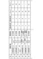
図3に示すように、ネットワークシステムでは、主演算装置100と各演算装置61~66,81~83との間の通信、及び各演算装置61~66,81~83同士の間の通信において、通信種別に応じた優先順位があらかじめ設定されている。優先順位は、例えば、通信内容の重要度、例えば、間引きした場合の影響度、安全性への寄与度、情報がなくてもリカバリー可能か否か等の基準に基づいて設定されている。より具体的に、例えば、制御種別による優先順位は、高いものから順に、走行制御、ADAS(Advanced driver-assistance systems:走行支援機能)関連の制御、ワイパーやライト等のボディ関連の制御、オーディオ等のエンターテイメント機器制御が設定される。走行制御の中では、制動制御(車両の停止動作)の優先順位が最も高く、次に、操舵制御(車両が曲がる動作)や駆動制御(車両の走行動作)の優先順位が高く設定される。ADAS関連の制御の中では、自動ブレーキ等の制動に関する制御の優先順位が最も高く、次に、操舵に関する制御や駆動に関する制御の優先順位が高く設定される。また、センサデバイス20の優先順位に関し、車両10の制御性能に影響が高い方のセンサデバイス20の通信の優先順位が高く設定される。例えば、ADAS関連の制御が、カメラ21とレーダ22の両方をコラボレーションさせて性能が発揮できるように構成され、一方の通信が停止しても性能が得られるようになっている場合に、カメラ21とレーダ22のうち、性能低下の度合いが高いセンサとの通信の優先順位が高く設定される。 As shown in FIG. 3, in the network system, in communication between the
なお、図3では、優先度が高い方から順に、「A」、「B」、「C」の符号が付されているものとする。以下の説明において、説明の便宜上、各演算装置61~66,81~83を総称して、単に「副演算装置」と呼ぶ場合がある。また、2つの通信経路R1,R2を介して主演算装置100に接続されているパワートレインECU81、ブレーキマイコン82及びEPASマイコン83の総称として、「副演算装置」と区別して「第1副演算装置」と呼ぶ場合がある。すなわち、副演算装置には、第1副演算装置のように複数の通信経路を介して主演算装置100に接続されている演算装置と、単一の通信経路に接続される演算装置との両方が含まれていてもよい。 Note that in FIG. 3, the symbols "A", "B", and "C" are assigned in descending order of priority. In the following description, for convenience of explanation, each of the
例えば、図3において、W1の行には、主演算装置100とパワートレインECU81との間の通信のうち、通信種別が「走行制御」についての優先順位が記載されている。「走行制御」とは、例えば、駆動力、制動力、操舵量のように、車両10の走行に関わる制御である。「走行制御」は、車両10の「主要機能」であり、制御の中でも優先度が非常に高いため、優先順位が「A」に設定されている。 For example, in the row W1 in FIG. 3, the priority order for the communication type "driving control" among the communications between the
同様にして、主演算装置100とブレーキマイコン82との間の「走行制御」の通信(W2の行参照)、パワートレインECU81とブレーキマイコン82との間の「走行制御」の通信(W3の行参照)、及び主演算装置100とEPASマイコン83との間の「走行制御」の通信(W6の行参照)について、通信の重要度を示す優先順位が「A」に設定されている。 Similarly, "driving control" communication between the
一方で、ボディ系の制御、例えば、主演算装置100とワイパー制御マイコン62との間の「ワイパー制御」の通信は、「走行制御」と比較すると、優先順位が低いため、優先順位が「C」に設定されている(W5の行参照)。同様に、ボディ系の制御である、主演算装置100とライト制御マイコン61との間の「ライト制御」の通信は、「走行制御」と比較すると、優先順位が低く設定されている(W4の行参照)。ただし、夜間の走行時における「ライト制御」は、「ワイパー制御」と比較すると、安全性の観点から優先順位が高い。そこで、「ライト制御」のうち、夜間の優先順位が「ワイパー制御」の「C」よりも高い「B」に設定され、昼間の優先順位が「ワイパー制御」と同じ「C」に設定されている。このように、同一の通信種別に対して、走行シーンや走行条件等に応じて複数の優先順位が設定されていてもよい。 On the other hand, body system control, for example, communication for "wiper control" between the
また、前述のとおり、主演算装置100と第1副演算装置との間は、2つの通信経路R1,R2を介して互いに接続されている。そこで、図3に示すように、第1副演算装置については、2つの通信経路R1,R2のうち、どの通信経路をメインの通信経路として使用するかをあらかじめ定めるようにしてもよい。図3では、主として使用する通信経路を「メインルート」と記載し、どこかの通信経路で途絶が生じた場合等に使用するサブの通信経路を「サブルート」と記載している。 Further, as described above, the
優先順位は、例えば、演算装置100の記憶部(図示省略)に格納されている。優先順位の格納形態は、特に限定されないが、例えば、図3のようなテーブルとして格納されている。なお、優先順位(例えば、テーブル)の格納場所は、演算装置100の記憶部に限定されない、例えば、ネットワークを構成するために設けられているハブ(図示省略)が参照できるようにするために、演算装置100に加えてまたは代えて、各ハブに優先順位が記憶されていてもよい。 The priority order is stored, for example, in a storage unit (not shown) of the
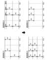
(通信量の制御1)
次に、図4を参照しつつ、ネットワークシステムの通信量の制御について説明する。図4の上段は、図2に示す放射状のネットワークシステムにおいて、通信の途絶が発生していない状態における通信量の一例を示す図であり、下段は、通信経路R21で通信の途絶が発生した場合(図2の「×印」参照)における通信量の一例を示す図である。なお、図4では、矢印の長さが通信量に対応しているものとする。また、パワートレインECU81、ブレーキマイコン82及びEPASマイコン83の相互間通信は、停止されているものとする。すなわち、図3のW3の行の通信は、行われていないものとする。また、図4及び後述する図5において、W1~W6は、図3のW1~W6の行の通信内容に対応しているものとし、説明の便宜上、通信データにも図3の行を示す符号と同じ符号を付すものとする。(Communication amount control 1)
Next, control of the communication amount of the network system will be explained with reference to FIG. 4. The upper part of FIG. 4 is a diagram showing an example of communication volume in a state where no communication interruption occurs in the radial network system shown in FIG. (See "X" in FIG. 2) is a diagram illustrating an example of communication volume. Note that in FIG. 4, the length of the arrow corresponds to the amount of communication. Further, it is assumed that communication between the
図4上段に示すように、通信量の途絶がない場合、通信経路R1には、主演算装置100とブレーキマイコン82との間の通信データW2、及び主演算装置100とライト制御マイコン61との間の通信データW4が伝送されている。通信経路R2では、主演算装置100とEPASマイコン83との間の通信データW6、主演算装置100とパワートレインECU81との間の通信データW1、及び主演算装置100とワイパー制御マイコン62との間の通信データW5が伝送されている。 As shown in the upper part of FIG. 4, when there is no interruption in the amount of communication, communication data W2 between the
図4下段に示すように、通信経路R21で通信の途絶が発生した場合、主演算装置100は、通信経路R1において、優先順位に基づいて、ライト制御マイコン61との間の通信(通信データW4)を停止する。さらに、主演算装置100は、通信経路R1において、ブレーキマイコン82との間の通信量(通信データW2)を減少させて、空いている通信帯域を広げている。さらに、主演算装置100は、途絶された通信経路R2を介して通信されていた、主演算装置100とパワートレインECU81との間の通信データW1、及び主演算装置100とEPASマイコン83との間の通信データW6を、別の通信経路である、通信経路R1を介して伝送している。また、主演算装置100とワイパー制御マイコン62との間の通信データW5は、優先順位に基づいて停止させている。 As shown in the lower part of FIG. 4, when a communication interruption occurs in the communication path R21, the
これにより、車載ネットワークの一部が途絶した場合に主要機能である、「走行制御」の機能が喪失されるのを防ぐことができる。なお、通信の途絶が発生した場合(図4下段の場合)に、優先順位等に応じて、通信データW1や通信データW6の通信量を減少させるようにしてもよい。 This can prevent loss of the main function, ``driving control,'' even if part of the in-vehicle network is interrupted. Note that when a communication interruption occurs (the case shown in the lower part of FIG. 4), the communication amount of the communication data W1 and the communication data W6 may be reduced depending on the priority order or the like.
(通信量の制御2)
次に、図5を参照しつつ、ネットワークシステムの通信量の他の制御について説明する。図5では、図4と同様に、上段に通信の途絶がない状態における通信量の一例を示し、下段に通信経路R21で通信の途絶が発生した場合(図2の「×印」参照)における通信量の一例を示している。また、図4の場合とは異なり、図面上段において、主演算装置100とライト制御マイコン61との間の通信(図3のW4に相当)が停止され、パワートレインECU81とブレーキマイコン82との間の通信(図3のW3に相当)が行われているものとする。(Communication amount control 2)
Next, with reference to FIG. 5, another control of the communication amount of the network system will be explained. In FIG. 5, similarly to FIG. 4, the upper row shows an example of the communication amount in a state where there is no communication interruption, and the lower row shows an example of the communication amount when a communication interruption occurs on the communication route R21 (see "X" in FIG. 2). An example of communication volume is shown. Also, unlike the case in FIG. 4, in the upper part of the drawing, communication between the
図5上段に示すように、通信量の途絶がない場合に、通信経路R1において、通信経路R11には、主演算装置100とブレーキマイコン82との間の通信データW2が伝送されている。また、通信経路R12及びR14には、パワートレインECU81とブレーキマイコン82との間の通信データW3が伝送されている。 As shown in the upper part of FIG. 5, when there is no interruption in the amount of communication, communication data W2 between the
同様に、通信量の途絶がない場合に、通信経路R2において、通信経路R21及びR23には、主演算装置100とEPASマイコン83との間の通信データW6、主演算装置100とパワートレインECU81との間の通信データW1、及び主演算装置100とワイパー制御マイコン62との間の通信データW5が伝送されている。また、通信経路R24には、通信データW1及び通信データW5が伝送され、通信経路R25には、通信データW5が伝送されている。 Similarly, in the communication path R2, when there is no interruption in the amount of communication, communication data W6 between the
図5下段に示すように、通信経路R21で通信の途絶が発生した場合に、主演算装置100は、パワートレインECU81とブレーキマイコン82との間の通信を停止させる。さらに、主演算装置100は、主演算装置100とブレーキマイコン82との間の通信量を減少させて、空いている通信帯域を広げている。さらに、主演算装置100は、途絶された通信経路R21を介して通信されていた、主演算装置100とパワートレインECU81との間の通信データW1、及び主演算装置100とEPASマイコン83との間の通信データW6を、別の通信経路である、通信経路R1を介して伝送している。これにより、車載ネットワークの一部が途絶した場合に主要機能である、「走行制御」の機能が喪失されるのを防ぐことができる。また、主演算装置100とワイパー制御マイコン62との間の通信データW5は、優先順位に基づいて停止させている。 As shown in the lower part of FIG. 5, when a communication interruption occurs in the communication path R21, the
さらに、主演算装置100は、通信経路R2のうち、途絶されていない通信経路である通信経路R22,R23,R24を用いて、パワートレインECU81及びブレーキマイコン82に、通信経路R12及びR14を介して行っていた両者間の通信を行わせている。これにより、車載ネットワークの一部が途絶した場合に主要機能である、「走行制御」の機能が喪失されるのを防ぐことができる。さらに、通信経路R2の中で、通信経路R1の通信を代替できる通信経路がある場合に、そちらの通信経路を活用することにより、通信量の低減を抑制することができる。 Furthermore, the
以上をまとめると、本実施形態に係る車載ネットワークシステムは、主演算装置100と、主演算装置100から放射状に延びる複数の通信経路R1~R4と、いずれかの通信経路を介して主演算装置100に接続された複数の副演算装置61~66,81~83とを備える。複数の副演算装置61~66,81~83は、複数の通信経路R1~R4を介して主演算装置100に接続された第1副演算装置65,66,81~83を含む。各通信経路R1~R4では、通信種別に応じた優先順位があらかじめ設定されている。主演算装置100は、第1副演算装置65,66,81~83と通信する通信経路R1~R4の一部に途絶が確認された場合に、通信経路R1~R4の残部において、優先順位が所定の基準よりも低い通信を減らし、減らした領域に第1副演算装置との通信のうち優先順位が所定の基準よりも高い通信を割り当てるように構成されている。 To summarize the above, the in-vehicle network system according to the present embodiment connects the
このように、主演算装置100と、第1副演算装置65,66,81~83との間を、少なくとも2つの通信経路R1~R4を介して互いに接続するようにしているので、1つの通信経路が途絶した場合においても、他の通信経路を介して通信することができる。また、一部の通信経路で途絶が確認された場合に、途絶されていない通信経路(通信経路の残部)において、通信種別に応じた優先順位にしたがって通信量を調整するようにしている、すなわち、優先順位が所定の基準よりも低い通信を減らし、減らした領域に主演算装置と第1副演算装置との通信のうち優先順位が所定の基準よりも高い通信を割り当てている。これにより、主要機能(上記実施形態では「走行制御」の機能)が喪失されるのを防ぐことができる。 In this way, since the
なお、「所定の基準」をどのように設定するかは特に限定されないが、例えば、「所定の基準」として、安全な走行を継続する上で必要な要素か否か、というように、安全性、走行性能等の必要機能を実現するのに必要な情報か否かを所定の基準としてもよい。特に、例えば、所定の基準として、走行制御の中でも、走行中の車両10が止まるのに必要な機能か否かが主要な基準となる。 There are no particular limitations on how the "predetermined standard" is set, but for example, whether or not the "predetermined standard" is a necessary element for continuing safe driving may be considered. , the predetermined criterion may be whether the information is necessary to realize a necessary function such as driving performance. Particularly, for example, as a predetermined criterion, the main criterion in travel control is whether or not the function is necessary for the
また、所定の基準よりも低い通信を減らす方法は、特に限定されないが、例えば、所定の基準や優先順位に応じて、通信周期を遅くしたり、1単位通信あたりの通信量を減らしたり、通信の間引きを行ったり、間引き率を従前よりも高める等を行うことで、通信量を減らすことができる。 There are no particular limitations on how to reduce communications that are lower than a predetermined standard, but examples include slowing down the communication cycle, reducing the amount of communication per unit of communication, etc. The amount of communication can be reduced by thinning out data or increasing the thinning rate compared to before.
なお、上記の実施形態において、互いに異なる通信経路R1~R4同士を接続する接続経路を設けるようにしてもよい。図示は省略するが、例えば、図2において、通信経路R1の経路R13と、通信経路R2の経路R25とを接続する接続経路を設けるようにしてもよい。また、例えば、図2において、通信経路R33の経路R33と、通信経路R4の経路R43とを接続する接続経路を設けるようにしてもよい。このような接続経路を設けることで、副演算装置のうちの第1副演算装置の数を増やすことができる。また、主演算装置と第1副演算装置との間を接続する互いに異なる通信経路の数を増やすことができる。 Note that in the above embodiment, a connection path may be provided that connects the different communication paths R1 to R4. Although not shown, for example, in FIG. 2, a connection path may be provided that connects the path R13 of the communication path R1 and the path R25 of the communication path R2. Further, for example, in FIG. 2, a connection path may be provided that connects the communication path R33 and the communication path R43. By providing such a connection path, the number of first sub-processing devices among the sub-processing devices can be increased. Furthermore, the number of different communication paths connecting the main processing device and the first sub-processing device can be increased.
ここに開示された技術は、車載用のネットワークシステムとして有用である。 The technology disclosed herein is useful as an in-vehicle network system.
100 主演算装置
61 ライト制御マイコン(副演算装置)
62 ワイパー制御マイコン(副演算装置)
63 左ドア制御マイコン(副演算装置)
64 右ドア制御マイコン(制御装置)
65 左監視装置(第1副演算装置)
66 右監視装置(第1副演算装置)
81 パワートレインECU(第1副演算装置)
82 ブレーキマイコン(第1副演算装置)
83 EPASマイコン(第1副演算装置)
R1,R2,R3,R4 通信経路100
62 Wiper control microcomputer (sub-processing unit)
63 Left door control microcomputer (sub-processing unit)
64 Right door control microcomputer (control device)
65 Left monitoring device (first sub-processing device)
66 Right monitoring device (first sub-processing device)
81 Powertrain ECU (first sub-processing unit)
82 Brake microcomputer (first sub-processing unit)
83 EPAS microcomputer (first sub-processing unit)
R1, R2, R3, R4 Communication path
Claims (3)
Translated fromJapanese前記主演算装置から車体の各所に向けて別々に延びる複数の通信経路と、
前記通信経路上に設けられ、それぞれに制御対象となる車載機器を制御する複数の副演算装置と、を含んでなる車載ネットワークシステムであって、
前記通信経路を伝送される通信データの種類に応じて通信の優先順位が記憶された記憶デバイスを有し、
少なくとも一の前記副演算装置は、前記複数の通信経路のうちの互いに異なる通信経路の両方を介して前記主演算装置に接続され、
前記主演算装置は、前記一の副演算装置に接続された一の通信経路が途絶した場合に、他の通信経路における通信を継続するにあたり、前記優先順位が所定の基準よりも低い通信データの通信量を減らし、当該減らした領域に前記途絶された通信経路で通信される通信データのうち前記優先順位が所定の基準よりも高い通信を割り当てるように構成され、
前記主演算装置から離れた位置において、前記一の副演算装置に接続された前記互いに異なる通信経路同士を接続する接続経路をさらに備える
ことを特徴とする車載ネットワークシステム。a main processing unitthat performs calculations related to vehicle running ;
a plurality of communication paths extendingseparately from the main processing unit to various parts of the vehicle body ;
An in-vehicle network system comprising a plurality of sub-processing devices provided on the communication path and each controlling an in-vehicle device to be controlled,
a storage device that stores communication priorities according to types of communication data transmitted through the communication path;
At least one of the sub-processing devices is connected to the main processing device via both different communication paths among the plurality of communication paths,
In the event that one communication path connected to the one sub-processing device is interrupted, the main processing unit may process communicationdata whose priority level is lower than a predetermined standard in order to continue communication on another communication path.configured to reducethe amount of communication and allocate to the reduced area communication whose priority is higher than a predetermined standard amongthe communication data communicated on the interrupted communication route,
Further comprising a connection path that connects the mutually different communication paths connected to the one sub-processing device at a position away from the main processing device.
An in-vehicle network system characterized by:
前記一の副演算装置は、パワートレイン装置、ブレーキ装置及び電動パワーステアリング装置を含む走行制御に係る車載機器のうち少なくとも1つを制御する副演算装置であるThe first sub-processing device is a sub-processing device that controls at least one of in-vehicle devices related to driving control including a power train device, a brake device, and an electric power steering device.
ことを特徴とする車載ネットワークシステム。An in-vehicle network system characterized by:
前記複数の副演算装置は、単一の前記通信経路を介して前記主演算装置に接続され、ボディ関係のデバイスを制御する、前記一の副演算装置と異なる他の副演算装置を含むThe plurality of sub-processing units include another sub-processing unit different from the one sub-processing unit, which is connected to the main processing unit via the single communication path and controls a body-related device.
ことを特徴とする車載ネットワークシステム。An in-vehicle network system characterized by:
Priority Applications (5)
| Application Number | Priority Date | Filing Date | Title |
|---|---|---|---|
| JP2019108202AJP7354601B2 (en) | 2019-06-10 | 2019-06-10 | In-vehicle network system |
| US17/616,676US20220332333A1 (en) | 2019-06-10 | 2020-03-17 | On-board network system |
| EP20823283.5AEP3944563A4 (en) | 2019-06-10 | 2020-03-17 | Onboard network system |
| PCT/JP2020/011616WO2020250529A1 (en) | 2019-06-10 | 2020-03-17 | Onboard network system |
| CN202080029808.6ACN113711543B (en) | 2019-06-10 | 2020-03-17 | Vehicle-mounted network system |
Applications Claiming Priority (1)
| Application Number | Priority Date | Filing Date | Title |
|---|---|---|---|
| JP2019108202AJP7354601B2 (en) | 2019-06-10 | 2019-06-10 | In-vehicle network system |
Publications (2)
| Publication Number | Publication Date |
|---|---|
| JP2020199880A JP2020199880A (en) | 2020-12-17 |
| JP7354601B2true JP7354601B2 (en) | 2023-10-03 |
Family
ID=73741813
Family Applications (1)
| Application Number | Title | Priority Date | Filing Date |
|---|---|---|---|
| JP2019108202AActiveJP7354601B2 (en) | 2019-06-10 | 2019-06-10 | In-vehicle network system |
Country Status (5)
| Country | Link |
|---|---|
| US (1) | US20220332333A1 (en) |
| EP (1) | EP3944563A4 (en) |
| JP (1) | JP7354601B2 (en) |
| CN (1) | CN113711543B (en) |
| WO (1) | WO2020250529A1 (en) |
Families Citing this family (1)
| Publication number | Priority date | Publication date | Assignee | Title |
|---|---|---|---|---|
| CN120034460A (en)* | 2023-11-22 | 2025-05-23 | 比亚迪股份有限公司 | A communication method and related device |
Citations (3)
| Publication number | Priority date | Publication date | Assignee | Title |
|---|---|---|---|---|
| JP2007228232A (en) | 2006-02-23 | 2007-09-06 | Auto Network Gijutsu Kenkyusho:Kk | In-vehicle LAN system, electronic control unit and relay connection unit |
| JP2008271040A (en) | 2007-04-18 | 2008-11-06 | Toyota Motor Corp | Communication device, communication system |
| JP2014034373A (en) | 2012-08-10 | 2014-02-24 | Mazda Motor Corp | Vehicle control system |
Family Cites Families (16)
| Publication number | Priority date | Publication date | Assignee | Title |
|---|---|---|---|---|
| WO2006002695A1 (en)* | 2004-07-06 | 2006-01-12 | Daimlerchrysler Ag | Redundant data bus system |
| JP2011020523A (en)* | 2009-07-14 | 2011-02-03 | Autonetworks Technologies Ltd | Method of supplying electric power to vehicle and power supply equipment for vehicle |
| JP2011240816A (en)* | 2010-05-18 | 2011-12-01 | Denso Corp | Autonomous running control system |
| US20120173905A1 (en)* | 2010-11-03 | 2012-07-05 | Broadcom Corporation | Providing power over ethernet within a vehicular communication network |
| US20140310075A1 (en)* | 2013-04-15 | 2014-10-16 | Flextronics Ap, Llc | Automatic Payment of Fees Based on Vehicle Location and User Detection |
| JP5769885B2 (en)* | 2012-07-17 | 2015-08-26 | 三菱電機株式会社 | Control apparatus and control method |
| JP6094439B2 (en)* | 2013-09-30 | 2017-03-15 | 株式会社デンソー | Vehicle control system |
| KR101481133B1 (en)* | 2013-12-12 | 2015-01-26 | 현대오트론 주식회사 | Vehicle communication system for transmitting data based on ethernet and method thereof |
| JP6485306B2 (en) | 2015-09-25 | 2019-03-20 | 株式会社デンソー | Control system |
| WO2017056688A1 (en)* | 2015-09-29 | 2017-04-06 | 日立オートモティブシステムズ株式会社 | Monitoring system and vehicle control device |
| JP6675487B2 (en)* | 2016-08-10 | 2020-04-01 | 日立オートモティブシステムズ株式会社 | Vehicle control device |
| CN106302064B (en)* | 2016-08-16 | 2019-03-08 | 新誉集团有限公司 | The data transfer optimization method and system of binary-channel redundancy CAN bus for electric vehicle |
| KR20190016294A (en)* | 2017-08-08 | 2019-02-18 | 삼성전자주식회사 | Electronic device and method for processing information associated with driving |
| JP7004534B2 (en)* | 2017-09-28 | 2022-02-10 | 株式会社Subaru | Vehicle control device and vehicle control method |
| JP6822386B2 (en)* | 2017-11-30 | 2021-01-27 | トヨタ自動車株式会社 | Formation running system |
| US10671067B2 (en)* | 2018-01-15 | 2020-06-02 | Qualcomm Incorporated | Managing limited safe mode operations of a robotic vehicle |
- 2019
- 2019-06-10JPJP2019108202Apatent/JP7354601B2/enactiveActive
- 2020
- 2020-03-17USUS17/616,676patent/US20220332333A1/ennot_activeAbandoned
- 2020-03-17EPEP20823283.5Apatent/EP3944563A4/ennot_activeCeased
- 2020-03-17CNCN202080029808.6Apatent/CN113711543B/enactiveActive
- 2020-03-17WOPCT/JP2020/011616patent/WO2020250529A1/ennot_activeCeased
Patent Citations (3)
| Publication number | Priority date | Publication date | Assignee | Title |
|---|---|---|---|---|
| JP2007228232A (en) | 2006-02-23 | 2007-09-06 | Auto Network Gijutsu Kenkyusho:Kk | In-vehicle LAN system, electronic control unit and relay connection unit |
| JP2008271040A (en) | 2007-04-18 | 2008-11-06 | Toyota Motor Corp | Communication device, communication system |
| JP2014034373A (en) | 2012-08-10 | 2014-02-24 | Mazda Motor Corp | Vehicle control system |
Also Published As
| Publication number | Publication date |
|---|---|
| JP2020199880A (en) | 2020-12-17 |
| EP3944563A4 (en) | 2022-06-15 |
| CN113711543A (en) | 2021-11-26 |
| CN113711543B (en) | 2023-01-31 |
| WO2020250529A1 (en) | 2020-12-17 |
| EP3944563A1 (en) | 2022-01-26 |
| US20220332333A1 (en) | 2022-10-20 |
Similar Documents
| Publication | Publication Date | Title |
|---|---|---|
| EP3936403B1 (en) | Travel control system for vehicle | |
| US12077184B2 (en) | Vehicle control system | |
| JP2019152896A (en) | Traveling control device, traveling control method, and program | |
| US11952000B2 (en) | Vehicle failure diagnostic device | |
| JP7243392B2 (en) | Vehicle running control device | |
| EP3907116A1 (en) | Vehicle travel control apparatus | |
| JP7354601B2 (en) | In-vehicle network system | |
| EP3925842B1 (en) | Travel control system | |
| CN113597389A (en) | Vehicle travel control device | |
| JP7354600B2 (en) | In-vehicle network system | |
| US20220321656A1 (en) | In-vehicle network system | |
| JP7372784B2 (en) | central processing unit |
Legal Events
| Date | Code | Title | Description |
|---|---|---|---|
| A621 | Written request for application examination | Free format text:JAPANESE INTERMEDIATE CODE: A621 Effective date:20220517 | |
| A131 | Notification of reasons for refusal | Free format text:JAPANESE INTERMEDIATE CODE: A131 Effective date:20230404 | |
| A521 | Request for written amendment filed | Free format text:JAPANESE INTERMEDIATE CODE: A523 Effective date:20230605 | |
| TRDD | Decision of grant or rejection written | ||
| A01 | Written decision to grant a patent or to grant a registration (utility model) | Free format text:JAPANESE INTERMEDIATE CODE: A01 Effective date:20230822 | |
| A61 | First payment of annual fees (during grant procedure) | Free format text:JAPANESE INTERMEDIATE CODE: A61 Effective date:20230904 | |
| R150 | Certificate of patent or registration of utility model | Ref document number:7354601 Country of ref document:JP Free format text:JAPANESE INTERMEDIATE CODE: R150 |