JP7352911B2 - System and method for controlling transport vehicles - Google Patents
System and method for controlling transport vehiclesDownload PDFInfo
- Publication number
- JP7352911B2 JP7352911B2JP2020040660AJP2020040660AJP7352911B2JP 7352911 B2JP7352911 B2JP 7352911B2JP 2020040660 AJP2020040660 AJP 2020040660AJP 2020040660 AJP2020040660 AJP 2020040660AJP 7352911 B2JP7352911 B2JP 7352911B2
- Authority
- JP
- Japan
- Prior art keywords
- transport vehicle
- target
- target position
- path
- controller
- Prior art date
- Legal status (The legal status is an assumption and is not a legal conclusion. Google has not performed a legal analysis and makes no representation as to the accuracy of the status listed.)
- Active
Links
Images


Classifications
- E—FIXED CONSTRUCTIONS
- E02—HYDRAULIC ENGINEERING; FOUNDATIONS; SOIL SHIFTING
- E02F—DREDGING; SOIL-SHIFTING
- E02F9/00—Component parts of dredgers or soil-shifting machines, not restricted to one of the kinds covered by groups E02F3/00 - E02F7/00
- E02F9/20—Drives; Control devices
- E02F9/2025—Particular purposes of control systems not otherwise provided for
- E02F9/2054—Fleet management
- E—FIXED CONSTRUCTIONS
- E02—HYDRAULIC ENGINEERING; FOUNDATIONS; SOIL SHIFTING
- E02F—DREDGING; SOIL-SHIFTING
- E02F9/00—Component parts of dredgers or soil-shifting machines, not restricted to one of the kinds covered by groups E02F3/00 - E02F7/00
- E02F9/20—Drives; Control devices
- E02F9/2025—Particular purposes of control systems not otherwise provided for
- E02F9/2045—Guiding machines along a predetermined path
- E—FIXED CONSTRUCTIONS
- E02—HYDRAULIC ENGINEERING; FOUNDATIONS; SOIL SHIFTING
- E02F—DREDGING; SOIL-SHIFTING
- E02F9/00—Component parts of dredgers or soil-shifting machines, not restricted to one of the kinds covered by groups E02F3/00 - E02F7/00
- E02F9/20—Drives; Control devices
- E02F9/2025—Particular purposes of control systems not otherwise provided for
- E02F9/205—Remotely operated machines, e.g. unmanned vehicles
- E—FIXED CONSTRUCTIONS
- E02—HYDRAULIC ENGINEERING; FOUNDATIONS; SOIL SHIFTING
- E02F—DREDGING; SOIL-SHIFTING
- E02F9/00—Component parts of dredgers or soil-shifting machines, not restricted to one of the kinds covered by groups E02F3/00 - E02F7/00
- E02F9/26—Indicating devices
- E02F9/261—Surveying the work-site to be treated
- E02F9/262—Surveying the work-site to be treated with follow-up actions to control the work tool, e.g. controller
- G—PHYSICS
- G05—CONTROLLING; REGULATING
- G05D—SYSTEMS FOR CONTROLLING OR REGULATING NON-ELECTRIC VARIABLES
- G05D1/00—Control of position, course, altitude or attitude of land, water, air or space vehicles, e.g. using automatic pilots
- G05D1/02—Control of position or course in two dimensions
- G05D1/021—Control of position or course in two dimensions specially adapted to land vehicles
- G05D1/0212—Control of position or course in two dimensions specially adapted to land vehicles with means for defining a desired trajectory
- E—FIXED CONSTRUCTIONS
- E02—HYDRAULIC ENGINEERING; FOUNDATIONS; SOIL SHIFTING
- E02F—DREDGING; SOIL-SHIFTING
- E02F3/00—Dredgers; Soil-shifting machines
- E02F3/04—Dredgers; Soil-shifting machines mechanically-driven
- E02F3/28—Dredgers; Soil-shifting machines mechanically-driven with digging tools mounted on a dipper- or bucket-arm, i.e. there is either one arm or a pair of arms, e.g. dippers, buckets
- E02F3/36—Component parts
- E02F3/42—Drives for dippers, buckets, dipper-arms or bucket-arms
- E02F3/43—Control of dipper or bucket position; Control of sequence of drive operations
- E02F3/435—Control of dipper or bucket position; Control of sequence of drive operations for dipper-arms, backhoes or the like
- E—FIXED CONSTRUCTIONS
- E02—HYDRAULIC ENGINEERING; FOUNDATIONS; SOIL SHIFTING
- E02F—DREDGING; SOIL-SHIFTING
- E02F3/00—Dredgers; Soil-shifting machines
- E02F3/04—Dredgers; Soil-shifting machines mechanically-driven
- E02F3/76—Graders, bulldozers, or the like with scraper plates or ploughshare-like elements; Levelling scarifying devices
- E02F3/80—Component parts
- E02F3/84—Drives or control devices therefor, e.g. hydraulic drive systems
- E02F3/841—Devices for controlling and guiding the whole machine, e.g. by feeler elements and reference lines placed exteriorly of the machine
Landscapes
- Engineering & Computer Science (AREA)
- Mining & Mineral Resources (AREA)
- Civil Engineering (AREA)
- General Engineering & Computer Science (AREA)
- Structural Engineering (AREA)
- Aviation & Aerospace Engineering (AREA)
- Radar, Positioning & Navigation (AREA)
- Remote Sensing (AREA)
- Physics & Mathematics (AREA)
- General Physics & Mathematics (AREA)
- Automation & Control Theory (AREA)
- Control Of Position, Course, Altitude, Or Attitude Of Moving Bodies (AREA)
Description
Translated fromJapanese本発明は、第1作業機械と第2作業機械との間で素材を運ぶ運搬車両を制御するためのシステム及び方法に関する。 The present invention relates to a system and method for controlling a transport vehicle that transports material between a first work machine and a second work machine.
油圧ショベルなどの作業機械によって土砂などの素材を掘削して、ダンプトラックなどの運搬車両に積み込む作業がある。運搬車両は、所定の積込位置で素材を積み込まれる。運搬車両は、所定のダンプ位置まで走行して、ダンプ位置で素材をダンプする。ダンプされた素材は、ブルドーザなどの作業機械によって敷きならされる。運搬車両はダンプ位置から積込位置へ戻り、作業機械によって再び素材が運搬車両に積み込まれる。従来、特許文献1に示されているように、上記のような運搬車両による運搬を自動制御によって行う技術が知られている。特許文献1では、処理装置などのコントローラが、運搬車両の目標経路を決定している。 There is work that involves excavating materials such as earth and sand using working machines such as hydraulic excavators and loading them onto transport vehicles such as dump trucks. The transport vehicle is loaded with material at a predetermined loading location. The transport vehicle travels to a predetermined dumping position and dumps the material at the dumping position. The dumped material is leveled by a working machine such as a bulldozer. The transport vehicle returns from the dump position to the loading position, and the work machine loads the material onto the transport vehicle again. Conventionally, as shown in
油圧ショベルは、掘削を行いながら移動する。また、ブルドーザも素材を敷きならしながら移動する。従って、運搬車両の目標経路は、これらの作業機械の作業状況に応じて変化する。そのため、最適な目標経路を決定することは容易ではない。また、最適な目標経路を決定するためには、コントローラへの負荷が大きくなる。本開示は、運搬車両の最適な目標経路を決定することを目的とする。 A hydraulic excavator moves while excavating. Bulldozers also move while leveling the material. Therefore, the target route of the transport vehicle changes depending on the working conditions of these working machines. Therefore, it is not easy to determine the optimal target route. Furthermore, determining the optimal target route increases the load on the controller. The present disclosure aims to determine an optimal target route for a transport vehicle.
本開示の一態様に係るシステムは、第1作業機械と第2作業機械との間で素材を運ぶ運搬車両を制御するためのシステムである。当該システムは、記憶装置とコントローラとを備える。コントローラは、記憶装置に接続されている。コントローラは、運搬車両の目標経路を示す静的パスを取得する。静的パスは、第1端点と第2端点とを含む。静的パスは、第1作業機械と第2作業機械との間に設定される。 A system according to one aspect of the present disclosure is a system for controlling a transport vehicle that transports materials between a first work machine and a second work machine. The system includes a storage device and a controller. The controller is connected to the storage device. The controller obtains a static path indicating a target route for the transport vehicle. The static path includes a first endpoint and a second endpoint. A static path is established between the first work machine and the second work machine.
コントローラは、第1作業機械の作業のための第1目標位置を取得する。コントローラは、第1端点と第1目標位置とを接続する第1動的パスを決定する。コントローラは、第2作業機械による作業のための第2目標位置を取得する。コントローラは、第2端点と第2目標位置とを接続する第2動的パスを決定する。コントローラは、静的パスと第1動的パスと第2動的パスとに従って運搬車両を走行させるように運搬車両を制御する。 The controller obtains a first target position for operation of the first work machine. The controller determines a first dynamic path connecting the first endpoint and the first target position. The controller obtains a second target position for work by the second work machine. The controller determines a second dynamic path connecting the second endpoint and the second target position. The controller controls the transport vehicle to travel according to the static path, the first dynamic path, and the second dynamic path.
本開示の他の態様に係る方法は、第1作業機械と第2作業機械との間で素材を運ぶ運搬車両を制御するためにコントローラによって実行される方法である。当該方法は、以下の処理を含む。第1の処理は、運搬車両の目標経路を示す静的パスを取得することである。静的パスは、第1端点と第2端点とを含む。静的パスは、第1作業機械と第2作業機械との間に設定される。 A method according to another aspect of the present disclosure is a method performed by a controller to control a transportation vehicle that transports material between a first work machine and a second work machine. The method includes the following processing. The first process is to obtain a static path indicating the target route of the transport vehicle. The static path includes a first endpoint and a second endpoint. A static path is established between the first work machine and the second work machine.
第2の処理は、第1作業機械の作業のための第1目標位置を取得することである。第3の処理は、第1端点と第1目標位置とを接続する第1動的パスを決定することである。第4の処理は、第2作業機械による作業のための第2目標位置を取得することである。第5の処理は、第2端点と第2目標位置とを接続する第2動的パスを決定することである。第6の処理は、静的パスと第1動的パスと第2動的パスとに従って運搬車両を走行させるように運搬車両を制御することである。なお、各処理の実行の順番は、上記の順番に関わらず変更されてもよい。 The second process is to obtain a first target position for the operation of the first work machine. The third process is to determine a first dynamic path connecting the first end point and the first target position. The fourth process is to obtain a second target position for work by the second work machine. The fifth process is to determine a second dynamic path connecting the second end point and the second target position. The sixth process is to control the transport vehicle to travel according to the static path, the first dynamic path, and the second dynamic path. Note that the order of execution of each process may be changed regardless of the above order.
本開示によれば、第1作業機械の作業のための第1目標位置に応じて第1動的パスが決定される。第2作業機械の作業のための第2目標位置に応じて第2動的パスが決定される。それにより、運搬車両の最適な走行経路を決定することができる。 According to the present disclosure, a first dynamic path is determined depending on a first target position for the operation of the first work machine. A second dynamic path is determined in response to a second target position for the operation of the second work machine. Thereby, the optimal travel route for the transport vehicle can be determined.
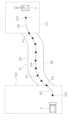
以下、実施形態に係る運搬車両の制御システムについて、図面を参照しながら説明する。図1は、運搬車両1が用いられる作業現場の一例を示す平面図である。作業現場には、運搬車両1と、第1作業機械2と、第2作業機械3とが配置されている。本実施形態において、第1作業機械2は、油圧ショベルである。運搬車両1は、ダンプトラックである。第2作業機械3は、ブルドーザである。 Hereinafter, a control system for a transport vehicle according to an embodiment will be described with reference to the drawings. FIG. 1 is a plan view showing an example of a work site where a
第1作業機械2は、作業現場内の第1作業領域101に配置されている。第2作業機械3は、作業現場内の第2作業領域102に配置されている。第1作業機械2は、第1作業領域101において掘削を行い、掘削された土などの素材を運搬車両1に積み込む。運搬車両1は、第1作業領域101から第2作業領域102への移動し、第2作業領域102において素材をダンプする。第2作業機械3は、第2作業領域102において、ダンプされた素材を敷きならす。運搬車両1は、素材をダンプした後、第2作業領域102から第1作業領域101へと戻る。運搬車両1は、作業現場内において、第1作業領域101と第2作業領域102との間を走行して往復する。このような作業が繰り返されることで、第1作業領域101内の素材が第2作業領域102に移送される。 The
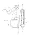
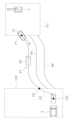
図2は、運搬車両1の側面図である。図2に示すように、運搬車両1は、車体10と、走行体11と、荷台12とを含む。車体10は、走行体11に支持されている。車体10は、走行体11に対して、旋回軸A1回りに、旋回可能である。車体10は、運転室13を含む。走行体11は、履帯14を含む。履帯14が駆動されることで、運搬車両1は走行する。走行体11は、第1走行体部15と第2走行体部16とを含む。第1走行体部15と第2走行体部16とは、運搬車両1の進行方向において互いに反対に位置する。第1走行体部15は、走行体11の前後方向における一方の端部であり、第2走行体部16は、走行体11の前後方向における他方の端部である。 FIG. 2 is a side view of the
荷台12は、車体10に支持されている。荷台12は、ダンプ姿勢と運搬姿勢とに動作可能に設けられている。図3において、実線で示す荷台12は、運搬姿勢の荷台12の位置を示している。二点鎖線で示す荷台12’は、ダンプ姿勢の荷台12の位置を示している。運搬姿勢では、荷台12は、概ね水平に配置される。ダンプ姿勢では、荷台12は、運搬姿勢に対して傾斜した状態となる。 The
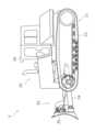
図3は、第1作業機械2の側面図である。図3に示すように、第1作業機械2は、車体21と作業機22とを含む。車体21は、旋回体23と走行体24とを含む。旋回体23は、走行体24に対して旋回可能に取り付けられている。旋回体23には運転室25が配置されている。走行体24は、履帯26を含む。履帯26が駆動されることで、第1作業機械2は走行する。 FIG. 3 is a side view of the first working
作業機22は、車体21の前部に取り付けられている。作業機22は、ブーム27とアーム28とバケット29とを含む。ブーム27は、旋回体23に対して上下方向に動作可能に取り付けられている。アーム28は、ブーム27に対して動作可能に取り付けられている。バケット29は、アーム28に対して動作可能に取り付けられている。ブーム27とアーム28とバケット29とには、それぞれ油圧シリンダが取り付けられている。油圧シリンダが伸縮することで、作業機22が動作する。 The
図4は、第2作業機械3の側面図である。図4に示すように、第2作業機械3は、車体30と、走行体31と、作業機32と、を備えている。車体30は、運転室36を含む。車体30は、走行体31に支持されている。走行体31は、履帯33を含む。履帯33が駆動されることで、第2作業機械3は走行する。 FIG. 4 is a side view of the second working
作業機32は、車体30に取り付けられている。作業機32は、リフトフレーム34とブレード35とを含む。リフトフレーム34は、上下に動作可能に車体30に取り付けられている。リフトフレーム34は、ブレード35を支持している。ブレード35は、リフトフレーム34の上下動に伴って上下に動作する。リフトフレーム34には、油圧シリンダが取り付けられている。油圧シリンダが伸縮することによって、作業機32は、上下に動作する。 The
図5は、運搬車両1の制御システムの構成を示すブロック図である。運搬車両1は、エンジン41と、油圧ポンプ42と、動力伝達装置43と、リフトシリンダ44と、旋回モータ45と、制御弁46とを含む。 FIG. 5 is a block diagram showing the configuration of the control system of the
油圧ポンプ42は、エンジン41によって駆動され、作動油を吐出する。なお、図5では、1つの油圧ポンプ42が図示されているが、複数の油圧ポンプが設けられてもよい。制御弁46は、リフトシリンダ44と油圧ポンプ42との間、及び、旋回モータ45と油圧ポンプ42との間に配置されている。制御弁46は、油圧ポンプ42からリフトシリンダ44に供給される作動油の流量を制御する。なお、制御弁46は、圧力比例制御弁であってもよい。或いは、制御弁46は、電磁比例制御弁であってもよい。 The
動力伝達装置43は、エンジン41の駆動力を走行体11に伝達する。動力伝達装置43は、例えば、HST(Hydro Static Transmission)である。 The
リフトシリンダ44は、油圧シリンダである。旋回モータ45は、油圧モータである。油圧ポンプ42から吐出された作動油は、リフトシリンダ44と旋回モータ45とに供給される。リフトシリンダ44と旋回モータ45とは、油圧ポンプ42からの作動油によって駆動される。リフトシリンダ44は、荷台12を昇降する。それにより、荷台12の姿勢が、運搬姿勢とダンプ姿勢とに切り換えられる。旋回モータ45は、走行体11に対して車体10を旋回させる。コントローラ48は、制御弁46によってリフトシリンダ44を制御することで、荷台12の動作を制御する。また、コントローラ48は、制御弁46によって旋回モータ45を制御することで、車体10の旋回を制御する。
運搬車両1は、位置センサ47を含む。位置センサ47は、例えばGNSS(Global Navigation Satellite System)レシーバとIMU(慣性計測装置:Inertial Measurement Unit)とを含む。位置センサ47は、運搬車両1の位置と、車体10の向きを検出し、位置データを出力する。位置データは、運搬車両1の位置を示すデータと、車体10の向きを示すデータとを含む。
運搬車両1は、コントローラ48と記憶装置49とを含む。コントローラ48はCPU或いはGPU等のプロセッサ50を含む。プロセッサ50は、運搬車両1の自動制御のための処理を行う。記憶装置49は、RAM或いはROMなどのメモリ、及び、HDD(Hard Disk Drive)或いはSSD(Solid State Drive)などの補助記憶装置を含む。記憶装置49は、運搬車両1の自動制御のためのデータ及びプログラムを記憶している。
コントローラ48は、位置センサ47及び記憶装置49と、有線、或いは無線によって通信可能に接続されている。コントローラ48は、位置センサ47から位置データを受信する。コントローラ48は、取得したデータに基づいて運搬車両1を制御するようにプログラムされている。コントローラ48は、エンジン41と走行体11と動力伝達装置43とを制御することで、運搬車両1を走行させる。コントローラ48は、エンジン41と油圧ポンプ42と制御弁46とを制御することで、荷台12を動作させる。コントローラ48は、エンジン41と油圧ポンプ42と制御弁46とを制御することで、走行体11に対して車体10を旋回させる。 The
図5に示すように、第1作業機械2は、コントローラ51と位置センサ52とを含む。第2作業機械3は、コントローラ53と位置センサ54とを含む。コントローラ51,53と位置センサ52,54とは、それぞれ運搬車両1のコントローラ48と位置センサ47と同様の構成を有している。第1作業機械2の位置センサ52は、第1作業機械2の位置と向きとを示すデータを出力する。第2作業機械3の位置センサ54は、第2作業機械3の位置と向きとを示すデータを出力する。 As shown in FIG. 5, the first working
運搬車両1は、通信装置55を含む。第1作業機械2は、通信装置56を含む。第2作業機械3は、通信装置57を含む。通信装置55-57は、例えば、無線LAN、或いはモバイル通信網などの通信ネットワークを介して、互いにデータ通信を行う。運搬車両1のコントローラ48は、通信装置55を介して、第1作業機械2のコントローラ51とデータ通信を行う。運搬車両1のコントローラ48は、通信装置55を介して、第2作業機械3のコントローラ53とデータ通信を行う。
運搬車両1のコントローラ48は、通信装置55を介して、入力装置58とデータ通信を行う。入力装置58は、マウスなどのポインティングデバイス、及びキーボードを含む。或いは、入力装置58は、タッチパネルを含んでもよい。入力装置58は、オペレータによって操作可能である。入力装置58は、オペレータによる入力操作を示す信号を、コントローラ48に送信する。入力装置58は、運搬車両1の外部に配置されてもよい。或いは、入力装置58は、運搬車両1内に配置されてもよい。 The
次に、運搬車両1のコントローラ48によって実行される自動制御の処理について説明する。コントローラ48は、図1に示すように運搬車両1の目標経路を示す走行パス60を決定する。コントローラ48は、図1に示す走行パス60に従って、運搬車両1を自動的に走行させる。走行パス60は、静的パス61と、第1動的パス62と、第2動的パス63とを含む。 Next, automatic control processing executed by the
静的パス61は、第1作業領域101と第2作業領域102との間に位置する。静的パス61は、第1作業機械2と第2作業機械3との作業に関わらずに規定される。第1動的パス62は、第1作業領域101内での運搬車両1の目標経路を示す。第1動的パス62は、第1作業機械2の作業に応じて変更される。第2動的パス63は、第2作業領域102内での運搬車両1の目標経路を示す。第2動的パス63は、第2作業機械3の作業に応じて変更される。
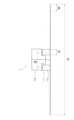
図6は、コントローラ48によって実行される自動制御の処理を示すフローチャートである。ステップS101では、コントローラ48は、静的パスデータを取得する。静的パスデータは、静的パス61の位置を示す。図7に示すように、静的パスデータは、第1端点P1と、第2端点P2と、第1端点P1と第2端点P2との間の複数点Pn(n=3,4,5,...)との座標を含む。なお、図7では、複数点Pnの一部のみに符号Pnが付されており、他の複数点Pnの符号は省略されている。 FIG. 6 is a flowchart showing automatic control processing executed by the
第1端点P1は、第1作業領域101側の静的パス61の端点である。第2端点P2は、第2作業領域102側の静的パス61の端点である。運搬車両1が第1作業領域101から第2作業領域102に向かって移動する場合(以下、「往路」と呼ぶ)、第1端点P1が静的パス61の始点であり、第2端点P2は静的パス61の終点である。運搬車両1が第2作業領域102から第1作業領域101に向かって移動する場合(以下、「復路」と呼ぶ)、第2端点P2が静的パス61の始点であり、第1端点P1は静的パス61の終点である。 The first end point P1 is the end point of the
静的パスデータは、予め設定されて、記憶装置49に保存されている。なお、コントローラ48は、通信ネットワークを介して外部のコンピュータから静的パスデータを取得してもよい。或いは、コントローラ48は、記録媒体を介して静的パスデータを取得してもよい。或いは、オペレータが、入力装置58を用いて、静的パス61を指定することで、コントローラ48が静的パスデータを生成してもよい。 The static path data is set in advance and stored in the
ステップS102では、コントローラ48は、静的パス61を決定する。図8に示すように、コントローラ48は、静的パスデータが示す経路を第1経路64として決定する。コントローラ48は、運搬車両1の左右方向に、第1経路64を所定距離L1だけオフセットさせた第2経路65を決定する。また、コントローラ48は、第2経路65と反対方向に、第1経路64を所定距離L1だけオフセットさせた第3経路66を決定する。コントローラ48は、例えば以下の式(1)から所定距離L1を算出する。
L1 = (H-B-D)/2 - M (1)In step S102, the
L1 = (HBD)/2 - M (1)
図9は、運搬車両1および運搬車両1の走行エリアの正面図である。図9に示すように、Hは、運搬車両1の走行エリアの幅を示し、作業現場に応じて規定されている。Bは、運搬車両1のゲージ幅である。Dは、履帯の幅である。Mは、マージンである。 FIG. 9 is a front view of the
コントローラ48は、第1経路64と第2経路65と第3経路66とを順次、切り替えて、静的パス61を決定する。例えば、コントローラ48は、往路では第1経路64を静的パス61として決定し、復路では第2経路65を静的パス61として決定してもよい。コントローラ48は、次の往路では第3経路66を静的パス61として決定し、次の復路では第1経路64を静的パス61として決定してもよい。或いは、コントローラ48は、1往復ごとに、第1経路64と第2経路65と第3経路66とに静的パス61を切り替えてもよい。或いは、コントローラ48は、オペレータによる入力装置58の操作に応じて、静的パス61を、第1経路64と第2経路65と第3経路66とのいずれかに切り替えてもよい。 The
ステップS103では、コントローラ48は、第1目標データを取得する。コントローラ48は、通信により、第1作業機械2のコントローラ51から第1目標データを取得する。図10に示すように、第1目標データは、第1作業領域101内での第1目標位置103の座標と、第1目標位置103での運搬車両1の第1目標方位104を含む。第1目標位置103は、第1作業領域101における運搬車両1の目標停車位置である。第1作業機械2は、第1目標位置103において運搬車両1に素材を積み込む。第1目標データは、第1作業機械2の作業に応じて変更される。第1作業機械2のコントローラ51は、第1作業機械2の位置及び向きに応じて、第1目標データを決定する。例えば、第1作業機械2のコントローラ51は、第1作業機械2の車体21の正面、或いは側面に対して、運搬車両1が正対するように、第1目標データを決定する。 In step S103, the
ステップS104では、コントローラ48は、第1動的パス62を決定する。図11に示すように、コントローラ48は、第1端点P1と第1目標位置103とを接続する経路を、第1動的パス62として決定する。コントローラ48は、運搬車両1の第1目標方位104に応じて、第1動的パス62を決定する。 In step S104, the
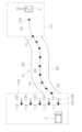
ステップS105では、コントローラ48は、第2目標データを取得する。コントローラ48は、通信により、第2作業機械3のコントローラ53から第2目標データを取得する。第2目標データは、第2目標位置105の座標と、第2目標位置105での運搬車両1の第2目標方位106とを含む。第2目標位置105は、第2作業領域102における運搬車両1の目標停車位置である。第2作業機械3は、第2目標位置105にダンプされた素材を敷きならす。第2目標データは、第2作業機械3の作業に応じて変更される。図12に示すように、第2目標データは、プリセットされた複数の目標点111-115の座標と、各目標点111-115での第2目標方位121-125とを含む。複数の目標点111-115は、第2作業領域102において、互いに所定間隔をおいて離れている。コントローラ48は、複数の目標点111-115のうち、第2作業機械3のコントローラ53から指定されたものを第2目標位置105として決定する。或いは、コントローラ48は、複数の目標点111-115を順に第2目標位置105として決定してもよい。 In step S105, the
ステップS106では、コントローラ48は、第2動的パス63を決定する。図13に示すように、コントローラ48は、第2端点P2と第2目標位置105とを接続する経路を、第2動的パス63として決定する。コントローラ48は、運搬車両1の第2目標方位106に応じて、第2動的パス63を決定する。 In step S106, the
ステップS107では、コントローラ48は、運搬車両1を制御する。コントローラ48は、運搬車両1が上述した第1動的パス62、静的パス61、第2動的パス63に従って走行するように、運搬車両1を制御する。なお、静的パス61の決定後であれば、第1動的パス62、或いは第2動的パス63の決定前であっても、コントローラ48は、運搬車両1が走行を開始するように制御してもよい。図14は、第1作業領域101から第2作業領域102に移動するときの運搬車両1を示している。図14に示すように、運搬車両1は、第1目標位置103において素材を積み込まれた後、第1目標位置103から第1動的パス62及び静的パス61を通って第2端点P2まで移動する。この間、運搬車両1は、第2走行体部16を前にして、静的パス61を第2作業領域102に向かって走行している。 In step S107, the
コントローラ48は、第2端点P2において、第2動的パス63への侵入の可否を決定する。例えば、コントローラ48は、第2作業機械3から第2目標データを適切に取得したときに、第2動的パス63への侵入を可能と決定する。コントローラ48は、第2作業機械3から第2目標データを適切に取得できなかったときに、第2動的パス63への侵入を不可と決定する。コントローラ48は、第2動的パス63への侵入を不可と決定したときには、第2作業機械3から第2目標データを適切に取得するまで、第2端点P2において運搬車両1を待機させる。 The
なお、コントローラ48は、第2端点P2以外の位置において、第2動的パス63への侵入の可否を決定してもよい。例えば、コントローラ48は、第1目標位置103において、第2動的パス63への侵入の可否を決定してもよい。或いは、コントローラ48は、第1動的パス62、或いは静的パス61での走行中に、第2動的パス63への侵入の可否を決定してもよい。 Note that the
コントローラ48は、第2作業機械3から第2目標データを適切に取得したときには、図15に示すように、運搬車両1を第2動的パス63に従って走行させ、第2目標位置105に停車させる。このとき、コントローラ48は、第2走行体部16を前にして第2目標位置105に運搬車両1を到着させる。コントローラ48は、走行体11に対して車体10を旋回させて、車体10の前後を入れ替える。そして、コントローラ48は、荷台12をダンプ姿勢に切り替えて、荷台12から素材をダンプする。 When the
図16は、第2作業領域102から第1作業領域101に移動するときの運搬車両1を示している。図16に示すように、運搬車両1が第2目標位置105から離れるときには、第1走行体部15を前にして運搬車両1を走行させる。図16に示すように、運搬車両1は、第2目標位置105において素材をダンプした後、第2目標位置105から第2動的パス63及び静的パス61を通って第1端点P1まで移動する。この間、運搬車両1は、第1走行体部15を前にして、静的パス61を第1作業領域101に向かって走行している。 FIG. 16 shows the
なお、図16に示す例では、コントローラ48は、復路では、往路と異なる静的パス61を決定している。例えば、コントローラ48は、第2経路65を復路での静的パス61として決定する。この場合、コントローラ48は、第2経路65の第2端点P2と第2目標位置105とを接続する経路を、第2動的パス63として決定する。 Note that in the example shown in FIG. 16, the
コントローラ48は、第1端点P1において、第1動的パス62への侵入の可否を決定する。例えば、コントローラ48は、第1作業機械2から第1目標データを適切に取得したときに、第1作業領域101への侵入を可能と決定する。コントローラ48は、第1作業機械2から第1目標データを適切に取得できなかったときに、第1作業領域101への侵入を不可と決定する。コントローラ48は、第1作業領域101への侵入を不可と決定したときには、第1作業機械2から第1目標データを適切に取得するまで、第1端点P1において運搬車両1を待機させる。 The
なお、コントローラ48は、第1端点P1以外の位置において、第1動的パス62への侵入の可否を決定してもよい。例えば、コントローラ48は、第2目標位置105において、第1動的パス62への侵入の可否を決定してもよい。或いは、コントローラ48は、第2動的パス63、或いは静的パス61での走行中に、第1動的パス62への侵入の可否を決定してもよい。 Note that the
コントローラ48は、第1作業機械2から第1目標データを適切に取得したときには、図17に示すように、第1端点P1と第1目標位置103とを接続する経路を、第1動的パス62として決定する。このとき、第1目標位置103が変更されている場合、コントローラ48は、変更された第1目標位置103と第1端点P1とを接続する経路を、第1動的パス62として決定する。コントローラ48は、運搬車両1を第1動的パス62に従って走行させ、第1目標位置103に停車させる。このとき、コントローラ48は、第1走行体部15を前にして第1目標位置103に運搬車両1を到着させる。コントローラ48は、走行体11に対して車体10を旋回させて、車体10の前後を入れ替える。そして、第1作業機械2が、運搬車両1の荷台12に素材を積み込む。コントローラ48は、上記の処理を繰り返し実行する。 When the
以上説明した本実施形態に係る運搬車両1の制御システムでは、第1作業機械2の作業のための第1目標位置103に応じて第1動的パス62が決定される。第2作業機械3の作業のための第2目標位置105に応じて第2動的パス63が決定される。それにより、運搬車両1の最適な走行パス60を決定することができる。 In the control system for the
以上、本発明の一実施形態について説明したが、本発明は上記実施形態に限定されるものではなく、発明の要旨を逸脱しない範囲で種々の変更が可能である。 Although one embodiment of the present invention has been described above, the present invention is not limited to the above embodiment, and various changes can be made without departing from the gist of the invention.
第1作業機械2は、油圧ショベルに限らず、ホイールローダ等の他の機械であってもよい。第2作業機械3は、ブルドーザに限らず、モータグレーダ等の他の機械であってもよい。第1作業機械2、及び/又は、第2作業機械3の構成は、上記の実施形態のものに限らず、変更されてもよい。例えば、第1作業機械2、及び/又は、第2作業機械3は、電動モータで駆動される車両であってもよい。第1作業機械2、及び/又は、第2作業機械3の運転室25,36は省略されてもよい。作業機22,32の構成は、上記の実施形態のものに限らず、変更されてもよい。第1作業機械2、及び/又は、第2作業機械3は、自動制御ではなく、オペレータによって手動で運転されてもよい。 The first working
運搬車両1は、ダンプトラック以外の車両であってもよい。運搬車両1の構成は、上記の実施形態のものに限らず、変更されてもよい。例えば、運搬車両1は、電動モータで駆動される車両であってもよい。走行体11及び/又は荷台12は、電動モータで駆動されてもよい。運搬車両1の荷台12は旋回不能であってもよい。運搬車両1の走行体11は、履帯14ではなく、タイヤを備えてもよい。動力伝達装置43は、HSTに限らず、トルクコンバーター、或いは複数の変速ギアを有するトランスミッションなどの他の方式の動力伝達装置であってもよい。運搬車両1の運転室13は省略されてもよい。 The
コントローラ48は、一体に限らず、複数のコントローラに分かれていてもよい。コントローラ48によって実行される処理は、複数のコントローラに分散して実行されてもよい。その場合、複数のコントローラ48の一部は、運搬車両1の外部に配置されてもよい。 The
第1作業機械2のコントローラ51と運搬車両1のコントローラ48とは、互いに直接的に通信するのではなく、他のコントローラを介して通信してもよい。第2作業機械3のコントローラ53と運搬車両1のコントローラ48とは、互いに直接的に通信するのではなく、他のコントローラを介して通信してもよい。 The
コントローラ48によって実行される自動制御モードの処理は、上述した実施形態のものに限らず、変更されてもよい。例えば、第1端点P1、或いは第2端点P2において運搬車両1を待機させる処理は省略されてもよい。第1端点P1、或いは第2端点P2において運搬車両1を待機させる制御のオン/オフが切り替え可能であってもよい。コントローラ48は、入力装置58からの信号に応じて、第1作業領域101、或いは第2作業領域102への侵入の可否を決定してもよい。 The automatic control mode processing executed by the
静的パス61の経路の数は3つに限らず、3つより少なくてもよく、或いは3つより多くてもよい。第1目標位置103を決定する処理が変更されてもよい。第2目標位置105を決定する処理が変更されてもよい。例えば、第1目標位置103を決定する処理と同様に、第2作業機械3のコントローラ53が、第2作業機械3の位置及び向きに応じて、第2目標位置105を決定してもよい。第2目標位置の複数の目標点の数は、5つに限らず、5つより少なくてもよく、5つより多くてもよい。 The number of
本開示によれば、最適な目標経路を決定することができる。 According to the present disclosure, an optimal target route can be determined.
1 運搬車両
2 第1作業機械
3 第2作業機械
15 第1走行体部
16 第2走行体部
49 記憶装置
48 コントローラ
61 静的パス
62 第1動的パス
63 第2動的パス
64 第1経路
65 第2経路
103 第1目標位置
105 第2目標位置
P1 第1端点
P2 第2端点1
Claims (18)
Translated fromJapanese記憶装置と、
前記記憶装置に接続されたコントローラと、
を備え、
前記コントローラは、
前記第1作業機械と前記第2作業機械との間に設定され、第1端点と第2端点とを含む前記運搬車両の目標経路を示す静的パスを取得し、
前記第1作業機械の作業のための第1目標位置を取得し、
前記第1端点と前記第1目標位置とを接続する第1動的パスを決定し、
プリセットされた複数の目標点と各目標点での第2目標方位とを取得し、
前記複数の目標点から選択されたものを前記第2作業機械による作業のための第2目標位置として決定し、
前記第2目標位置に対応する前記第2目標方位に応じて、前記第2端点と前記第2目標位置とを接続する第2動的パスを決定し、
前記静的パスと前記第1動的パスと前記第2動的パスとに従って前記運搬車両を走行させるように前記運搬車両を制御する、
システム。A system for controlling a transport vehicle that transports materials between a first working machine and a second working machine, the system comprising:
a storage device;
a controller connected to the storage device;
Equipped with
The controller includes:
obtaining a static path that is set between the first working machine and the second working machine and indicating a target route of the transport vehicle that includes a first end point and a second end point;
obtaining a first target position for work of the first work machine;
determining a first dynamic path connecting the first end point and the first target position;
Obtaining a plurality of preset target points and a second target direction at each target point,
determiningone selected from the plurality of target pointsas a second target position for work by the second working machine;
determininga second dynamic path connecting the second end point and the second target position according to the second target orientation corresponding to the second target position;
controlling the transport vehicle to run the transport vehicle according to the static path, the first dynamic path, and the second dynamic path;
system.
請求項1に記載のシステム。the first target position is changed according to the work of the first working machine;
The system of claim 1.
前記第1作業機械から前記第1目標位置を取得する、
請求項2に記載のシステム。The controller includes:
obtaining the first target position from the first work machine;
The system according to claim 2.
前記第1目標位置での前記運搬車両の目標方位を取得し、
前記目標方位に応じて、前記第1動的パスを決定する、
請求項2又は3に記載のシステム。The controller includes:
obtaining a target orientation of the transport vehicle at the first target position;
determining the first dynamic path according to the target orientation;
The system according to claim 2 or 3.
前記第1動的パスへの侵入の可否を決定し、
前記第1動的パスへの侵入を不可と決定したときには、前記第1端点において前記運搬車両を待機させる、
請求項2から4のいずれかに記載のシステム。The controller includes:
determining whether or not the first dynamic path can be invaded;
When it is determined that entry into the first dynamic path is not possible, causing the transport vehicle to wait at the first end point;
A system according to any one of claims 2 to 4.
請求項1から5のいずれかに記載のシステム。the second target position is changed according to the work of the second working machine;
A system according to any one of claims 1 to 5.
前記第2動的パスへの侵入の可否を決定し、
前記第2動的パスへの侵入を不可と決定したときには、前記第2端点において前記運搬車両を待機させる、
請求項1から6のいずれかに記載のシステム。The controller includes:
determining whether or not the second dynamic path can be invaded;
When it is determined that entry into the second dynamic path is not possible, causing the transport vehicle to wait at the second end point;
A system according toany one of claims 1 to 6 .
前記第1作業機械と前記第2作業機械との作業に関わらずに規定される第1経路を取得し、
前記第1経路を前記第1経路の幅方向に、所定距離だけオフセットさせた第2経路を取得し、
前記第1経路と前記第2経路とを切り替えて前記静的パスを決定する、
請求項1から7のいずれかに記載のシステム。The controller includes:
obtaining a first route defined regardless of work between the first working machine and the second working machine;
obtaining a second route by offsetting the first route by a predetermined distance in the width direction of the first route;
determining the static path by switching between the first route and the second route;
A system according to any one of claims 1 to7 .
前記コントローラは、
前記運搬車両が、前記第1走行体部を前にして、前記静的パスを前記第1動的パスに向かって走行しているときには、前記第1走行体部を前にして前記第1目標位置に前記運搬車両を到着させ、
前記第1目標位置から離れるときには、前記第2走行体部を前にして前記運搬車両を走行させる、
請求項1から8のいずれかに記載のシステム。The transportation vehicle includes a first traveling body portion and a second traveling body portion located opposite to each other in the traveling direction of the transportation vehicle,
The controller includes:
When the transport vehicle is traveling along the static path toward the first dynamic path with the first traveling body section in front, the transport vehicle is traveling toward the first target with the first traveling body section in front of it. Arriving the transport vehicle at a location;
When leaving the first target position, the transport vehicle is run with the second traveling body section in front;
A system according to any one of claims1 to 8 .
前記コントローラは、
前記運搬車両が、前記第2走行体部を前にして、前記静的パスを前記第2動的パスに向かって走行しているときには、前記第2走行体部を前にして前記第2目標位置に前記運搬車両を到着させ、
前記第2目標位置から離れるときには、前記第1走行体部を前にして前記運搬車両を走行させる、
請求項1から9のいずれかに記載のシステム。The transportation vehicle includes a first traveling body portion and a second traveling body portion located opposite to each other in the traveling direction of the transportation vehicle,
The controller includes:
When the transport vehicle is traveling along the static path toward the second dynamic path with the second traveling body section in front, the transport vehicle is traveling toward the second target with the second traveling body section in front of it. Arriving the transport vehicle at a location;
When leaving the second target position, the transport vehicle is driven with the first traveling body section in front;
A system according to any one of claims1 to 9 .
前記第1作業機械と前記第2作業機械との間に設定され、第1端点と第2端点とを含む前記運搬車両の目標経路を示す静的パスを取得することと、
前記第1作業機械の作業のための第1目標位置を取得することと、
前記第1端点と前記第1目標位置とを接続する第1動的パスを決定することと、
プリセットされた複数の目標点と各目標点での第2目標方位とを取得することと、
前記複数の目標点から選択されたものを前記第2作業機械による作業のための第2目標位置として決定することと、
前記第2目標位置に対応する前記第2目標方位に応じて、前記第2端点と前記第2目標位置とを接続する第2動的パスを決定することと、
前記静的パスと前記第1動的パスと前記第2動的パスとに従って前記運搬車両を走行させるように前記運搬車両を制御すること、
を備える方法。A method performed by a controller for controlling a transport vehicle transporting material between a first work machine and a second work machine, the method comprising:
obtaining a static path that is set between the first working machine and the second working machine and that indicates a target route of the transport vehicle that includes a first end point and a second end point;
obtaining a first target position for the operation of the first work machine;
determining a first dynamic path connecting the first endpoint and the first target position;
obtaining a plurality of preset target points and a second target direction at each target point;
determiningone selected from the plurality of target pointsas a second target position for work by the second work machine;
determininga second dynamic path connecting the second end point and the second target position according to the second target orientation corresponding to the second target position;
controlling the transport vehicle to travel according to the static path, the first dynamic path, and the second dynamic path;
How to prepare.
請求項11に記載の方法。the first target position is changed according to the work of the first working machine;
The method according to claim11 .
請求項12に記載の方法。the first target position is obtained from the first work machine;
13. The method according to claim12 .
前記目標方位に応じて、前記第1動的パスを決定すること、
をさらに備える請求項12又は13に記載の方法。obtaining a target orientation of the transport vehicle at the first target position;
determining the first dynamic path according to the target orientation;
14. The method according to claim12 or 13 , further comprising:
前記第1動的パスへの侵入を不可と決定したときには、前記第1端点において前記運搬車両を待機させること、
をさらに備える請求項12から14のいずれかに記載の方法。determining whether to invade the first dynamic path;
When it is determined that entry into the first dynamic path is not possible, causing the transport vehicle to wait at the first end point;
15. The method according to any one of claims12 to 14, further comprising:
請求項11から15のいずれかに記載の方法。the second target position is changed according to the work of the second working machine;
A method according to any one of claims11 to 15 .
前記第2動的パスへの侵入を不可と決定したときには、前記第2端点において前記運搬車両を待機させること、
をさらに備える請求項11から16のいずれかに記載の方法。determining whether to invade the second dynamic path;
When it is determined that entry into the second dynamic path is not possible, causing the transport vehicle to wait at the second end point;
17. The method according toany one of claims 11 to 16, further comprising:
前記第1経路を前記第1経路の幅方向に、所定距離だけオフセットさせた第2経路を取得することと、
前記第1経路と前記第2経路とを切り替えて前記静的パスを決定すること、
をさらに備える請求項11から17のいずれかに記載の方法。obtaining a first route defined regardless of work between the first working machine and the second working machine;
obtaining a second route by offsetting the first route by a predetermined distance in the width direction of the first route;
determining the static path by switching between the first route and the second route;
18. The method according to any one of claims11 to 17, further comprising:
Priority Applications (5)
| Application Number | Priority Date | Filing Date | Title |
|---|---|---|---|
| JP2020040660AJP7352911B2 (en) | 2020-03-10 | 2020-03-10 | System and method for controlling transport vehicles |
| CA3163110ACA3163110A1 (en) | 2020-03-10 | 2021-03-04 | System and method for controlling transport vehicle |
| US17/781,071US20230003003A1 (en) | 2020-03-10 | 2021-03-04 | System and method for controlling transport vehicle |
| PCT/JP2021/008450WO2021182297A1 (en) | 2020-03-10 | 2021-03-04 | System and method for controlling transport vehicle |
| AU2021235367AAU2021235367B2 (en) | 2020-03-10 | 2021-03-04 | System and method for controlling transport vehicle |
Applications Claiming Priority (1)
| Application Number | Priority Date | Filing Date | Title |
|---|---|---|---|
| JP2020040660AJP7352911B2 (en) | 2020-03-10 | 2020-03-10 | System and method for controlling transport vehicles |
Publications (2)
| Publication Number | Publication Date |
|---|---|
| JP2021144274A JP2021144274A (en) | 2021-09-24 |
| JP7352911B2true JP7352911B2 (en) | 2023-09-29 |
Family
ID=77670867
Family Applications (1)
| Application Number | Title | Priority Date | Filing Date |
|---|---|---|---|
| JP2020040660AActiveJP7352911B2 (en) | 2020-03-10 | 2020-03-10 | System and method for controlling transport vehicles |
Country Status (5)
| Country | Link |
|---|---|
| US (1) | US20230003003A1 (en) |
| JP (1) | JP7352911B2 (en) |
| AU (1) | AU2021235367B2 (en) |
| CA (1) | CA3163110A1 (en) |
| WO (1) | WO2021182297A1 (en) |
Families Citing this family (1)
| Publication number | Priority date | Publication date | Assignee | Title |
|---|---|---|---|---|
| US12071746B2 (en)* | 2021-05-12 | 2024-08-27 | Deere & Company | System and method for assisted positioning of transport vehicles relative to a work machine during material loading |
Citations (3)
| Publication number | Priority date | Publication date | Assignee | Title |
|---|---|---|---|---|
| WO2000026735A1 (en) | 1998-11-04 | 2000-05-11 | Komatsu Ltd. | Device for guiding vehicle |
| WO2016167375A1 (en) | 2016-04-28 | 2016-10-20 | 株式会社小松製作所 | Management device for construction machinery |
| WO2017104329A1 (en) | 2015-12-18 | 2017-06-22 | 株式会社小松製作所 | Work machine management system, work machine control system, and work machine |
Family Cites Families (8)
| Publication number | Priority date | Publication date | Assignee | Title |
|---|---|---|---|---|
| US5931875A (en)* | 1996-12-19 | 1999-08-03 | Caterpillar Inc. | System and method for managing a fleet of mobile machines for dumping at a plurality of dump points |
| JP5140887B2 (en)* | 2006-11-07 | 2013-02-13 | 株式会社小松製作所 | Unmanned vehicle guided traveling control method and control device |
| JP6498542B2 (en)* | 2015-06-17 | 2019-04-10 | 日立建機株式会社 | Control control system and in-vehicle terminal device |
| AU2016248872A1 (en)* | 2016-04-28 | 2017-11-16 | Komatsu Ltd. | Work machine management apparatus |
| CA2992244C (en)* | 2017-03-31 | 2020-06-30 | Komatsu Ltd. | Control system for work vehicle, work vehicle, and control method for work vehicle |
| US10640121B2 (en)* | 2017-04-28 | 2020-05-05 | International Business Machines Corporation | Vehicle control for reducing road wear |
| US20200150656A1 (en)* | 2018-11-12 | 2020-05-14 | Alberto Daniel Lacaze | Autonomous Trucks with Specialized Behaviors for Mining and Construction Applications |
| US11401690B2 (en)* | 2019-11-15 | 2022-08-02 | Built Robotics Inc. | Filling earth into a vehicle using a cooperative fleet of vehicles |
- 2020
- 2020-03-10JPJP2020040660Apatent/JP7352911B2/enactiveActive
- 2021
- 2021-03-04WOPCT/JP2021/008450patent/WO2021182297A1/ennot_activeCeased
- 2021-03-04AUAU2021235367Apatent/AU2021235367B2/enactiveActive
- 2021-03-04CACA3163110Apatent/CA3163110A1/enactivePending
- 2021-03-04USUS17/781,071patent/US20230003003A1/ennot_activeAbandoned
Patent Citations (3)
| Publication number | Priority date | Publication date | Assignee | Title |
|---|---|---|---|---|
| WO2000026735A1 (en) | 1998-11-04 | 2000-05-11 | Komatsu Ltd. | Device for guiding vehicle |
| WO2017104329A1 (en) | 2015-12-18 | 2017-06-22 | 株式会社小松製作所 | Work machine management system, work machine control system, and work machine |
| WO2016167375A1 (en) | 2016-04-28 | 2016-10-20 | 株式会社小松製作所 | Management device for construction machinery |
Also Published As
| Publication number | Publication date |
|---|---|
| JP2021144274A (en) | 2021-09-24 |
| AU2021235367B2 (en) | 2023-09-28 |
| WO2021182297A1 (en) | 2021-09-16 |
| US20230003003A1 (en) | 2023-01-05 |
| AU2021235367A1 (en) | 2022-06-09 |
| CA3163110A1 (en) | 2021-09-16 |
Similar Documents
| Publication | Publication Date | Title |
|---|---|---|
| JP6159031B2 (en) | Work machine management device | |
| JP6243538B2 (en) | Transport machine management device and transport machine management method | |
| JP7261111B2 (en) | WORKING MACHINE AND METHOD OF CONTROLLING WORKING MACHINE | |
| WO2020075458A1 (en) | System and method including transport vehicle and work machine for loading raw materials into transport vehicle, and work machine | |
| KR20110069942A (en) | Position control device and position control method for construction equipment | |
| JP7245581B2 (en) | Systems and methods for controlling work machines that load materials onto haul vehicles | |
| US12421694B2 (en) | Work machine, method for controlling work machine, and execution management device | |
| CN111684136A (en) | Control device for working machine and control method for working machine | |
| CN114174598A (en) | Construction machine | |
| JP7352911B2 (en) | System and method for controlling transport vehicles | |
| JP7352463B2 (en) | System and method for controlling work machines | |
| WO2022080334A1 (en) | Work vehicle control system, work vehicle control method, and work vehicle | |
| JP6701125B2 (en) | Work machine management method | |
| JP7382908B2 (en) | System and method for controlling work machines | |
| JP7519870B2 (en) | Method and system for controlling a work machine, and work machine | |
| JP7416769B2 (en) | Work vehicle, work vehicle control device, and work vehicle direction identification method | |
| JP2019139809A (en) | Management device for work machine and method for managing work machine | |
| JP7558030B2 (en) | Method and system for controlling a bulldozer and a haul vehicle - Patents.com | |
| JP2024144799A (en) | Control device, control method and working machine | |
| JP2024144798A (en) | Control device, control method and working machine | |
| JP2024144797A (en) | Control device, control method and working machine | |
| JP2024144800A (en) | Control device, control method and working machine | |
| WO2022113602A1 (en) | Control system for loading equipment, method, and loading equipment | |
| JP2025005596A (en) | System for controlling a work machine | |
| JP2025146136A (en) | Work machinery |
Legal Events
| Date | Code | Title | Description |
|---|---|---|---|
| A621 | Written request for application examination | Free format text:JAPANESE INTERMEDIATE CODE: A621 Effective date:20230214 | |
| A131 | Notification of reasons for refusal | Free format text:JAPANESE INTERMEDIATE CODE: A131 Effective date:20230530 | |
| A521 | Request for written amendment filed | Free format text:JAPANESE INTERMEDIATE CODE: A523 Effective date:20230727 | |
| TRDD | Decision of grant or rejection written | ||
| A01 | Written decision to grant a patent or to grant a registration (utility model) | Free format text:JAPANESE INTERMEDIATE CODE: A01 Effective date:20230829 | |
| A61 | First payment of annual fees (during grant procedure) | Free format text:JAPANESE INTERMEDIATE CODE: A61 Effective date:20230908 | |
| R150 | Certificate of patent or registration of utility model | Ref document number:7352911 Country of ref document:JP Free format text:JAPANESE INTERMEDIATE CODE: R150 | |
| S531 | Written request for registration of change of domicile | Free format text:JAPANESE INTERMEDIATE CODE: R313531 | |
| S533 | Written request for registration of change of name | Free format text:JAPANESE INTERMEDIATE CODE: R313533 | |
| R350 | Written notification of registration of transfer | Free format text:JAPANESE INTERMEDIATE CODE: R350 |