JP7352790B2 - Motors for power tools and power tools - Google Patents
Motors for power tools and power toolsDownload PDFInfo
- Publication number
- JP7352790B2 JP7352790B2JP2019068211AJP2019068211AJP7352790B2JP 7352790 B2JP7352790 B2JP 7352790B2JP 2019068211 AJP2019068211 AJP 2019068211AJP 2019068211 AJP2019068211 AJP 2019068211AJP 7352790 B2JP7352790 B2JP 7352790B2
- Authority
- JP
- Japan
- Prior art keywords
- substrate
- motor
- power tool
- insulator
- board
- Prior art date
- Legal status (The legal status is an assumption and is not a legal conclusion. Google has not performed a legal analysis and makes no representation as to the accuracy of the status listed.)
- Active
Links
Images


Classifications
- H—ELECTRICITY
- H02—GENERATION; CONVERSION OR DISTRIBUTION OF ELECTRIC POWER
- H02K—DYNAMO-ELECTRIC MACHINES
- H02K7/00—Arrangements for handling mechanical energy structurally associated with dynamo-electric machines, e.g. structural association with mechanical driving motors or auxiliary dynamo-electric machines
- H02K7/14—Structural association with mechanical loads, e.g. with hand-held machine tools or fans
- H02K7/145—Hand-held machine tool
- H—ELECTRICITY
- H02—GENERATION; CONVERSION OR DISTRIBUTION OF ELECTRIC POWER
- H02K—DYNAMO-ELECTRIC MACHINES
- H02K11/00—Structural association of dynamo-electric machines with electric components or with devices for shielding, monitoring or protection
- H02K11/20—Structural association of dynamo-electric machines with electric components or with devices for shielding, monitoring or protection for measuring, monitoring, testing, protecting or switching
- H02K11/21—Devices for sensing speed or position, or actuated thereby
- H—ELECTRICITY
- H02—GENERATION; CONVERSION OR DISTRIBUTION OF ELECTRIC POWER
- H02K—DYNAMO-ELECTRIC MACHINES
- H02K11/00—Structural association of dynamo-electric machines with electric components or with devices for shielding, monitoring or protection
- H02K11/30—Structural association with control circuits or drive circuits
- H02K11/33—Drive circuits, e.g. power electronics
- H—ELECTRICITY
- H02—GENERATION; CONVERSION OR DISTRIBUTION OF ELECTRIC POWER
- H02K—DYNAMO-ELECTRIC MACHINES
- H02K29/00—Motors or generators having non-mechanical commutating devices, e.g. discharge tubes or semiconductor devices
- H02K29/06—Motors or generators having non-mechanical commutating devices, e.g. discharge tubes or semiconductor devices with position sensing devices
- H—ELECTRICITY
- H02—GENERATION; CONVERSION OR DISTRIBUTION OF ELECTRIC POWER
- H02K—DYNAMO-ELECTRIC MACHINES
- H02K5/00—Casings; Enclosures; Supports
- H02K5/04—Casings or enclosures characterised by the shape, form or construction thereof
- H02K5/15—Mounting arrangements for bearing-shields or end plates
- H—ELECTRICITY
- H02—GENERATION; CONVERSION OR DISTRIBUTION OF ELECTRIC POWER
- H02K—DYNAMO-ELECTRIC MACHINES
- H02K2211/00—Specific aspects not provided for in the other groups of this subclass relating to measuring or protective devices or electric components
- H02K2211/03—Machines characterised by circuit boards, e.g. pcb
- H—ELECTRICITY
- H02—GENERATION; CONVERSION OR DISTRIBUTION OF ELECTRIC POWER
- H02K—DYNAMO-ELECTRIC MACHINES
- H02K5/00—Casings; Enclosures; Supports
- H02K5/04—Casings or enclosures characterised by the shape, form or construction thereof
- H02K5/22—Auxiliary parts of casings not covered by groups H02K5/06-H02K5/20, e.g. shaped to form connection boxes or terminal boxes
- H02K5/225—Terminal boxes or connection arrangements
Landscapes
- Engineering & Computer Science (AREA)
- Power Engineering (AREA)
- Microelectronics & Electronic Packaging (AREA)
- Portable Power Tools In General (AREA)
- Connection Of Motors, Electrical Generators, Mechanical Devices, And The Like (AREA)
Description
Translated fromJapanese本開示は、一般に電動工具用モータ及び電動工具に関し、より詳細にはセンサ素子を有する電動工具用モータ及び電動工具に関する。 The present disclosure generally relates to a power tool motor and a power tool, and more particularly to a power tool motor and a power tool having a sensor element.
特許文献1には、電動工具が開示されている。この電動工具は、ステータコイルを有するモータと、回路基板とを備えている。ステータコイルは、コイル本体部と、コイル本体部から引き出されて回路基板に電気的に接続された引出し部とを有する。
特許文献1には、インバータ回路基板上にスイッチング素子、及び位置検出素子等が搭載されている。そして、インバータ回路基板よりも後端側にベアリングが設けられている。このような構成を有するモータでは、回転軸が長くなってたわみやすくなり、騒音及び振動の一因となり得る。 In
本開示の目的は、低騒音、低振動、及び高効率が可能である電動工具用モータ及び電動工具を提供することにある。 An object of the present disclosure is to provide a motor for a power tool and a power tool that are capable of low noise, low vibration, and high efficiency.
本開示の一態様に係る電動工具用モータは、回転軸を有するロータと、前記ロータを回転させるコイルを有するステータと、前記ロータの回転位置を検出するセンサ素子が実装された基板と、前記回転軸を回転可能に支持するベアリングと、前記ステータ、前記基板、及び前記ベアリングを固定するインシュレータと、を備える。 A motor for a power tool according to an aspect of the present disclosure includes a rotor having a rotating shaft, a stator having a coil for rotating the rotor, a substrate mounted with a sensor element that detects a rotational position of the rotor, and a rotor that rotates the rotor. The apparatus includes a bearing that rotatably supports a shaft, and an insulator that fixes the stator, the substrate, and the bearing.
本開示の一態様に係る電動工具は、前記電動工具用モータと、前記電動工具用モータが収容された電動工具本体と、を備える。 A power tool according to one aspect of the present disclosure includes the power tool motor and a power tool main body in which the power tool motor is housed.
本開示によれば、低騒音、低振動、及び高効率が可能である。 According to the present disclosure, low noise, low vibration, and high efficiency are possible.
1.概要
本実施形態に係る電動工具用モータ1は、ブラシレスモータである。電動工具用モータ1は、例えばドリルドライバ及びインパクトドライバ等の電動工具10の駆動源として用いられる。1. Overview The
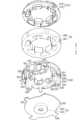
図1に示すように、電動工具用モータ1は、ロータ2と、ステータ3と、基板41(第1基板41)と、ベアリング7(第2ベアリング72)と、インシュレータ5と、を備える。ロータ2は、回転軸21を有する。ステータ3は、コイル31を有する。コイル31は、ロータ2を回転させる。第1基板41には、センサ素子410が実装されている(図4参照)。センサ素子410は、ロータ2の回転位置を検出する素子である。第2ベアリング72は、回転軸21を回転可能に支持する。 As shown in FIG. 1, the
本実施形態では、インシュレータ5は、ステータ3、第1基板41、及び第2ベアリング72を固定するので、低騒音、低振動、及び高効率が可能である。 In this embodiment, since the
2.詳細
<電動工具用モータ>
図1に示すように、本実施形態に係る電動工具用モータ1は、ロータ2と、ステータ3と、第1基板41と、第2基板42と、インシュレータ5と、ヒートシンク6と、2つのベアリング7(第1ベアリング71及び第2ベアリング72)と、端子部材8(図2参照)と、を備える。2. Details <Motor for power tools>
As shown in FIG. 1, the
以下、特に断りがない限り、回転軸21の方向を「上下方向」とし、回転軸21の一端側を「上方」、他端側を「下方」として説明する。つまり、図1において、「上」及び「下」の矢印で示す通りに上及び下の各方向を規定する。ただし、これらの方向は電動工具用モータ1の使用方向を規定する趣旨ではない。図面中の各方向を示す矢印は説明のために表記しているに過ぎず、実体を伴わない。 Hereinafter, unless otherwise specified, the direction of the
≪ロータ≫
ロータ2は、回転する部材である。ロータ2は、回転軸21と、ロータ本体20と、複数の永久磁石22(本実施形態では4つ)と、冷却ファン23と、を有する。≪Rotor≫
The
回転軸21は、ロータ本体20に貫通して固定されている。 The rotating
ロータ本体20は、回転軸21を中心として、回転軸21の方向に延びる円柱状をなしている。ロータ本体20の上面及び下面は、回転軸21の方向に対して垂直である。 The
永久磁石22は、ロータ本体20内に埋め込まれている。複数の永久磁石22は、回転軸21の周方向に均等に配置されている。
冷却ファン23は、ロータ本体20の上面においてロータ本体20及び回転軸21に固定されている。冷却ファン23は、上面視において円形であり、全体的にハット状をなしている。冷却ファン23は、窪み部230を有する。窪み部230は、第1ベアリング71が収容される空間部分である。窪み部230は、冷却ファン23の中央部において、下方に窪んでいる部分である。ロータ2は、回転軸21の周方向に回転可能である。 The
≪ステータ≫
ステータ3は、ロータ2の外周に配置されている。ステータ3は、鉄心30と、コイル31と、を有する。≪Stator≫
The
図3に示すように、鉄心30は、筒部300と、複数の歯部301(本実施形態では6つ)と、を有する。筒部300は、回転軸21の方向に延びる円筒状をなしている。6つの歯部301は、筒部300の周方向において内周面に等間隔で設けられている。6つの歯部301の各々は、上面視において略T字状をなしている。 As shown in FIG. 3, the
コイル31は、ロータ2を回転させる部材である。コイル31は、6つの歯部301に配線310が巻回されて形成されている(図1参照)。コイル31は、電動工具用モータ1の使用時において、冷却ファン23によって冷却される。 The
≪第1基板≫
第1基板41は、いわゆるセンサ基板である。すなわち、第1基板41は、ロータ2の回転位置を検出するための回路基板である。≪First board≫
The
第1基板41は、ロータ本体20の下方において、ロータ本体20の下面と平行に配置されている。第1基板41には、センサ素子410が実装されている。センサ素子410は、例えばホール素子等である。センサ素子410は、ロータ2の回転位置を検出する素子である。 The
図4に示すように、第1基板41は、上面視において略C字状をなしている。第1基板41は、回転軸21の外周の略半周を囲んでいる。つまり、第1基板41は、回転軸21の周方向の一部に配置されている。このように、第1基板41は、回転軸21の周囲全体に配置する必要がないので、第1基板41の使用量を減らすことが可能となる。 As shown in FIG. 4, the
第1基板41は、接続部43(第1接続部431)と、複数の取付孔411(本実施形態では2つ)と、複数の位置決め孔412(本実施形態では2つ)と、を有する。 The
第1接続部431は、外部機器(不図示)と電気的に接続するための部材である。第1接続部431は、例えばコネクタ及びパッド等である。センサ素子410による位置検出信号は、第1接続部431を通って外部機器に送信される。第1接続部431は、第1基板41の外周縁部に設けられている。第1接続部431の外部機器との接続方向は、回転軸21の径方向外向きである(図4中、矢印431Dで示す)。接続方向は、リード線(不図示)の引出方向等である。なお、外部機器は、例えば制御回路等を含むマイコン等である。 The first connecting
取付孔411は、第1基板41をインシュレータ5に固定するのに用いられる孔である。取付孔411は、第1基板41の外周縁部に設けられている。取付孔411は、第1基板41を上下方向に貫通している。 The
位置決め孔412は、第1基板41をインシュレータ5に固定する際の位置決めに用いられる孔である。位置決め孔412は、第1基板41の外周縁部に設けられている。位置決め孔412は、第1基板41を上下方向に貫通している。 The
≪第2基板≫
第2基板42は、いわゆるスイッチング基板である。すなわち、第2基板42は、ステータ3のコイル31への通電方向を切り替えるための回路基板である。第2基板42は、インバータ回路を含む。≪Second board≫
The
第2基板42は、第1基板41の下方において、第1基板41と平行に配置されている。第2基板42には、スイッチング素子(不図示)が実装されている。スイッチング素子は、例えば電界効果トランジスタ(FET)等である。スイッチング素子は、センサ素子410の検出結果に応じてコイル31への通電方向を切り替える素子である。 The
図4に示すように、第2基板42は、円形部420と、張出部423と、を有する。 As shown in FIG. 4, the
円形部420は、上面視において略円形状をなしている。円形部420の外径は、ステータ3の外径と略同一である。円形部420は、複数の第1切欠き421(本実施形態では5つ)と、複数の第2切欠き422(本実施形態では3つ)と、を有する。 The
第1切欠き421は、第2基板41をヒートシンク6に固定するのに用いられる切欠きである。第1切欠き421は、円形部420の外周縁部に設けられている。第1切欠き421は、上面視において略半円状をなしている。第1切欠き421は、回転軸21の径方向外側に開口している。 The
第2切欠き422は、ヒートシンク6をインシュレータ5に固定するのに用いられる切欠きである。第2切欠き422は、円形部420の外周縁部に設けられている。第2切欠き422は、上面視において略半円状をなしている。第2切欠き422は、回転軸21の径方向外側に開口している。 The
張出部423は、上面視において略矩形状をなしている。張出部423は、円形部420の外周の一部から、回転軸21の径方向外側に張り出した部分である。上方から第1基板41及び第2基板42を重ねて見ると、第2基板42の張出部423は、第1基板41の外周縁からはみ出している。このように、回転軸21の径方向において、第1基板41及び第2基板42の長さが異なっている。つまり、張出部423は、第1基板41及び第2基板42の長さの差に相当する部分といえる。この部分には、各種の部品が実装可能である。特に、第1基板41と第2基板42との間隔よりも大きい部品の実装に有効である。すなわち、第2基板42の張出部423の上面に大きな部品を実装しても、第1基板41は邪魔にならない。むしろ第1基板41と第2基板42との間隔を狭めることが可能となる。このように、第1基板41と第2基板42との長さが異なることで、各種部品の実装スペースを確保することができる。 The projecting
張出部423は、接続部43(第2接続部432)を有する。第2接続部432は、外部機器(不図示)と電気的に接続するための部材である。第2接続部432は、例えばコネクタ及びパッド等である。外部機器からの駆動信号は、第2接続部432を通って第2基板42に送信される。受信した駆動信号に基づいて、コイル31への通電方向が切り替えられて、ロータ2が回転する。第2接続部432は、張出部423の上面に配置されている。 The projecting
第2接続部432は、第1接続部431と同様に、回転軸21と直交する一方向の一方側に配置されている。つまり、第1接続部431と第2接続部432とは、同じ側に配置されている。言い換えると、第1接続部431と第2接続部432とは、回転軸21と直交する一方向の一方側と、他方側とに分かれて配置されていない。第1接続部431と第2接続部432とが別々の側に配置されていると、各々の側でリード線(不図示)との接続等のための空間を確保する必要があるが、第1接続部431と第2接続部432とが同じ側に配置されていると、リード線との接続等のための空間を一つにまとめることができる。したがって、電動工具用モータ1の小型化が可能となる。 The second connecting
第2接続部432の外部機器との接続方向は、回転軸21の軸方向上向きである(図1中、矢印432Dで示す)。このように、第1接続部431及び第2接続部432の外部機器との接続方向が異なっている。接続方向が同じであれば、接続方向と異なる方向にデッドスペースが生じるおそれがある。上記のように接続方向を異ならせることで、デッドスペースを少なくすることができる。 The connection direction of the
≪第1基板及び第2基板の位置関係≫
図1に示すように、第1基板41及び第2基板42は、回転軸21の方向に沿って並んでいる。つまり、第1基板41と第2基板42とは、上下にそれぞれ配置されている。第1基板41及び第2基板42は、回転軸21に対して直交している。具体的には、第1基板41のセンサ素子410が実装された面と、第2基板42のスイッチング素子が実装された面とは、回転軸21に対して垂直である。≪Positional relationship between the first substrate and the second substrate≫
As shown in FIG. 1, the
第1基板41は、回転軸21の方向において、ステータ3と第2基板42との間に配置されている。すなわち、ステータ3、第1基板41、及び第2基板42は、上段、中段、及び下段にそれぞれ位置している。 The
本実施形態では、センサ素子410及びスイッチング素子は、単一の基板に実装されずに、第1基板41及び第2基板42にそれぞれ分けて実装されている。これにより、ロータ2と第1基板41との距離、及びステータ3と第2基板42との距離を、各々独立して調整することができる。すなわち、センサ素子410は、ロータ2に近いほど、ロータ2の回転位置を精度よく検出することができる。これにより、電動工具用モータ1の高トルク出力が可能となる。一方、スイッチング素子は、ステータ3のコイル31から遠いほど、コイル31の発熱の影響を受けにくくなる。これにより、電動工具用モータ1の連続使用時間を長くすることができる。 In this embodiment, the
≪インシュレータ≫
インシュレータ5は、電気絶縁性を有する部材である。インシュレータ5は、例えばナイロン等の樹脂製である。≪Insulator≫
The
インシュレータ5は、ステータ3、第1基板41、及び第2基板42を固定している。図3に示すように、インシュレータ5は、第1インシュレータ51、第2インシュレータ52、及び第3インシュレータ53を含む。第1インシュレータ51及び第2インシュレータ52は、インサート成形により、ステータ3の鉄心30と一体化している。 The
第1インシュレータ51は、鉄心30の上部を被覆している。具体的には、第1インシュレータ51は、円環部510と、複数の歯部被覆部514(本実施形態では歯部301と同数の6つ)と、を有する。 The
円環部510の外径は、鉄心30の筒部300の外径と略同一である。円環部510は、筒部300の上面を被覆している。 The outer diameter of the
6つの歯部被覆部514は、円環部510の周方向において内周面に等間隔で設けられている。6つの歯部被覆部514の各々は、6つの歯部301の各々の上面を被覆している。 The six
第2インシュレータ52は、鉄心30の下部を被覆している。具体的には、第2インシュレータ52は、円環部520と、複数の歯部被覆部524(本実施形態では歯部301と同数の6つ)と、第1取付部521(本実施形態では2つ)と、位置決め部525(本実施形態では2つ)と、第2取付部522(本実施形態では3つ)と、端子保護部523と、を有する。なお、第2インシュレータ52の第2取付部522の一部は、回転軸21の方向において、ステータ3と第2基板42との間に配置されている。 The
円環部520の外径は、鉄心30の筒部300の外径と略同一である。円環部520は、筒部300の下面を被覆している。 The outer diameter of the
6つの歯部被覆部524は、円環部520の周方向において内周面に等間隔で設けられている。6つの歯部被覆部524の各々は、6つの歯部301の各々の下面を被覆している。なお、図2に示すように、具体的には、コイル31は、上下の歯部被覆部514,524で被覆された歯部301に配線310が巻回されて形成されている。 The six
第1取付部521は、第1基板41を取り付けるための部分である。第1取付部521は、円環部520の下面から下方に突出している。2つの第1取付部521の突出長さは等しい。第1取付部521は、ねじ孔526を有する。ねじ孔526は、第1取付部521の先端面(下端面)に設けられている。 The
位置決め部525は、第1基板41を第2インシュレータ52に固定する際の位置決めに用いられる部分である。位置決め部525は、円環部520の下面から下方に突出している。2つの位置決め部525の突出長さは、第1取付部521の突出長さに等しい。位置決め部525は、突起527を有する。突起527は、位置決め部525の先端面(下端面)から突出している。突起527を第1基板41の上から位置決め孔412に通すことにより、第1基板41の位置決めを行うことができる。 The
第2取付部522は、第2基板42を取り付けるための部分である。第2取付部522は、円環部520の下面から下方に突出している。3つの第2取付部522の突出長さは等しい。第2取付部522は、ねじ孔528を有する。ねじ孔528は、第2取付部522の先端面(下端面)に設けられている。 The
第2取付部522の突出長さは、第1取付部521の突出長さよりも長い。このように、第1取付部521と第2取付部522とは、回転軸21の方向においてずれて配置されている。 The protrusion length of the
端子保護部523は、円環部520の下面から下方に突出している。端子保護部523の突出長さは、第2取付部522の突出長さと略同一である。図2に示すように、端子保護部523は、第2基板42と接触している。 The
第3インシュレータ53は、回転軸21の方向において、ステータ3と第2基板42との間に配置されている。これにより、ステータ3、及び第2基板42を電気的に絶縁することができる。さらに第3インシュレータ53は、第1基板41と第2基板42との間に配置されている。第3インシュレータ53は、円筒部531と、フランジ部532と、取付孔533と、支持部534と、を有する。 The
円筒部531は、第2ベアリング72が収容される部分である(図1参照)。円筒部531は、回転軸21の方向に延びる円筒状をなしている。円筒部531は、上方に開口している。回転軸21の方向において、円筒部531の長さは、第1基板41と第2基板42との間隔に略等しい。 The
フランジ部532は、第1基板41を支持する部分である。フランジ部532は、円筒部531の上端縁から、回転軸21の径方向外向きに張り出し、上面視において略円形状をなしている。フランジ部532の外径は、ステータ3の外径と略同一である。 The
取付孔533は、第1基板41と一緒に第3インシュレータ53を第2インシュレータ52に固定するのに用いられる孔である。取付孔533は、第3インシュレータ53の外周縁部に設けられている。取付孔533は、第3インシュレータ53を上下方向に貫通している。図2に示すように、ねじ541を第3インシュレータ53の下から取付孔533、及び第1基板41の取付孔411に通し、第1取付部521のねじ孔526に締め付けることにより、第1基板41と一緒に第3インシュレータ53を第2インシュレータ52に固定することができる。 The
支持部534は、第1基板41と一緒に第3インシュレータ53を第2インシュレータ52に固定する際に、第1基板41の位置決め孔412の周辺部分を、第2インシュレータ52の位置決め部525と挟み込んで支持する部分である。 When fixing the
≪ヒートシンク≫
ヒートシンク6は、放熱性を有する部材である。ヒートシンク6は、例えばアルミニウム等の金属製である。≪Heat sink≫
The
ヒートシンク6は、上面視において、ステータ3の外径と略同一の外径を有する円の外周の一部が欠けた形状をなしている。ヒートシンク6は、第2基板42の下方に配置されている。ヒートシンク6は、ねじ穴600(本実施形態では5つ)と、取付部601(本実施形態では3つ)と、を有する。 The
ねじ穴600は、第2基板42をヒートシンク6に取り付けるための穴である。ねじ穴600は、ヒートシンク6の外周縁部に設けられている。図1に示すように、ねじ424を第2基板42の上から第1切欠き421に通し、ヒートシンク6のねじ穴600に締め付けることにより、第2基板42をヒートシンク6に固定することができる。 The
取付部601は、ヒートシンク6を第2インシュレータ52に取り付けるための部分である。図1に示すように、取付部601は、ヒートシンク6の上面から上方に突出している。取付部601の外径は、第2基板42の第2切欠き422の内径に略等しい。取付部601は、取付孔602を有する。取付孔602は、取付部601を上下方向に貫通している。取付部601を第2基板42の下から第2切欠き422に通し、さらにねじ542をヒートシンク6の下から取付孔602に通し、第2インシュレータ52の第2取付部522のねじ孔528に締め付ける。これにより、ヒートシンク6を第2インシュレータ52に固定することができる。このように、ヒートシンク6を介して第2基板42がインシュレータ5に固定されている。これにより、電動工具用モータ1の放熱性を向上させることができる。特に第2基板42がヒートシンク6に取り付けられていることで、第2基板42の放熱性を向上させることができる。なお、第2基板42とヒートシンク6との間には、両者を電気的に絶縁しつつ熱的に接触させるために、絶縁シート603が介在している。 The
≪ベアリング≫
2つのベアリング7(第1ベアリング71及び第2ベアリング72)は、回転軸21を回転可能に支持する。≪Bearing≫
The two bearings 7 (
第1ベアリング71は、回転軸21の方向において冷却ファン23よりも上方に位置している。第1ベアリング71は、冷却ファン23の窪み部230に収容されている。第1ベアリング71の厚さ(回転軸21の方向における長さ)は、窪み部230の深さ(回転軸21の方向における長さ)よりも短い。 The
第2ベアリング72は、回転軸21の方向においてステータ3よりも下方に位置している。第2ベアリング72は、第2基板42よりも上方に位置している。第2ベアリング72は、第3インシュレータ53の円筒部531に収容されている。そのため、回転軸21の方向において、第2ベアリング72の最外面721(下面)よりも内側(上側)に、第1基板41が配置されている。これにより、電動工具用モータ1の長さ(回転軸21の方向における長さ)をより短くすることができるので、電動工具用モータ1の小型化が可能となる。第2ベアリング72の厚さ(回転軸21の方向における長さ)は、円筒部531の深さ(回転軸21の方向における長さ)よりも長い。そのため、第2ベアリング72の一部は、第3インシュレータ53のフランジ部532の上面から突出している。この突出している分だけ、第1基板41と第2ベアリング72とは、回転軸21の径方向から見たときに重なっている。この重なっている部分を図2中、OLで示す。重なっている部分OLが長いほど電動工具用モータ1の長さをより短くすることができるので、電動工具用モータ1の小型化が可能となる。 The
本実施形態では、第2ベアリング72が、ステータ3と第2基板42との間に配置されていることで、回転軸21を短くすることができる。回転軸21が短くなることで、ロータ2の回転時にたわみにくくなるので、騒音、及び振動を低減することができる。 In this embodiment, the
また、第2ベアリング72が、ステータ3と第2基板42との間に配置されていることで、第2基板42に、回転軸21を挿通させるための貫通孔を設ける必要がなくなる。貫通孔を設けなければ、その分、回路の形成箇所を確保することができる。つまり、回路設計の自由度を高めることができる。したがって、電動工具用モータ1の高効率が可能である。 Furthermore, since the
さらに電動工具用モータ1は、第2ベアリング72による片持ち構造を採用していることで、ロータ2とステータ3との間隔をより狭くすることができる。間隔が狭くなることで、電動工具用モータ1の効率を上げることができる。 Furthermore, since the
≪端子部材≫
端子部材8は、コイル31と第2基板42とを電気的に接続するための部材である。図2に示すように、端子部材8は、インシュレータ5に固定されている。具体的には、端子部材8の少なくとも一部は、インサート成形により、第2インシュレータ52の端子保護部523内に埋め込まれている。このように、端子部材8は、端子保護部523によって保護されている。端子部材8は、導電性を有する。端子部材8は、例えば金属板で形成されている。端子部材8の断面積は、コイル31の配線310の断面積よりも大きい。端子部材8の一端(上端)にコイル31の配線310が電気的に接続されている。端子部材8の他端(下端)に第2基板42が電気的に接続されている。このように、第2基板42は、端子部材8を介してコイル31に電気的に接続されている。コイル31の配線310を引き延ばして直接、第2基板42に電気的に接続することも可能であるが、配線310と第2基板42との間に端子部材8を介在させることで、配線310の断線を抑制することができる。≪Terminal member≫
The
<電動工具>
本実施形態に係る電動工具10は、例えばドリルドライバ及びインパクトドライバ等である。<Power tools>
The
図6に示すように、電動工具10は、電動工具用モータ1と、電動工具本体9と、装着部91と、保持部92と、トリガ93と、台座部94と、を備える。 As shown in FIG. 6, the
電動工具本体9は、略円筒状をなす部材である。電動工具本体9は、電動工具用モータ1を収容する。 The power tool
装着部91は、電動工具本体9の先端に接続されている。装着部91は、電動工具10の使用用途に応じた形状のビットを、電動工具本体9に対して回転自在な状態で装着するための部分である。装着部2では、回転伝達機構を通じて伝達された回転力をビットに加えることで、ビットを電動工具本体9に対して回転させることができる。 The mounting
保持部92は、使用時に電動工具10を保持するための部材である。保持部92は、電動工具本体9の側方に接続されている。 The holding
トリガ93は、電動工具用モータ1を駆動又は停止させるスイッチである。トリガ93は、保持部92に配置されている。トリガ93は、保持部92側に押し込むことが可能となっている。トリガ93が保持部92側に押し込まれると、電動工具用モータ1に電力が供給され、回転軸21が回転する。外部から力が加えられていない場合には、トリガ93は、保持部92内に配置されたばね等(不図示)により、保持部92から突出した状態を維持する。したがって、回転軸21が回転している状態で、トリガ93を保持部92側へ押し込む力を取り除いた場合には、トリガ93が保持部92から突出し、電動工具用モータ1への電力供給が中止され、回転軸21の回転が停止する。 The
台座部94は、電動工具10を床等の平坦面に置いて直立させることができるようにするための部材である。台座部94は、保持部92の先端に接続され、平坦な底面を有する。 The
なお、図示省略しているが、電動工具10は、電動工具用モータ1の回転軸21の回転力を装着部91に伝達するための回転伝達機構、充電池、及びトリガ93の状態に応じて充電池からの電力を電動工具用モータ1に供給するための回路等も備える。 Although not shown, the
3.まとめ
上記実施形態から明らかなように、本開示は、下記の態様を含む。なお、以下では、実施形態との対応関係を明示するためだけに、符号を括弧付きで付している。3. Summary As is clear from the above embodiments, the present disclosure includes the following aspects. In addition, in the following, the reference numerals are given in parentheses only to clearly indicate the correspondence with the embodiments.
第1の態様に係る電動工具用モータ(1)は、回転軸(21)を有するロータ(2)と、前記ロータ(2)を回転させるコイル(31)を有するステータ(3)と、前記ロータ(2)の回転位置を検出するセンサ素子(410)が実装された基板(41)と、前記回転軸(21)を回転可能に支持するベアリング(7;72)と、前記ステータ(3)、前記基板(41)、及び前記ベアリング(7;72)を固定するインシュレータ(5;52)と、を備える。 A power tool motor (1) according to a first aspect includes a rotor (2) having a rotating shaft (21), a stator (3) having a coil (31) for rotating the rotor (2), and a stator (3) having a coil (31) for rotating the rotor (2). (2) a substrate (41) mounted with a sensor element (410) for detecting the rotational position of the rotary shaft (21), a bearing (7; 72) that rotatably supports the rotation shaft (21), and the stator (3); It includes an insulator (5; 52) that fixes the substrate (41) and the bearing (7; 72).
この態様によれば、低騒音、低振動、及び高効率が可能である。 According to this aspect, low noise, low vibration, and high efficiency are possible.
第2の態様に係る電動工具用モータ(1)では、第1の態様において、前記基板(41)は、前記回転軸(21)の方向において、前記ベアリング(7;72)の最外面(721)よりも内側に配置されている。 In the electric tool motor (1) according to the second aspect, in the first aspect, the substrate (41) is arranged on the outermost surface (721) of the bearing (7; 72) in the direction of the rotation axis (21). ) is placed inside.
この態様によれば、電動工具用モータ(1)の小型化が可能となる。 According to this aspect, it is possible to downsize the electric tool motor (1).
第3の態様に係る電動工具用モータ(1)では、第2の態様において、前記基板(41)と前記ベアリング(7;72)とは、径方向から見たときに重なっている。 In the electric tool motor (1) according to the third aspect, in the second aspect, the substrate (41) and the bearing (7; 72) overlap when viewed from the radial direction.
この態様によれば、電動工具用モータ(1)の小型化が可能となる。 According to this aspect, it is possible to downsize the electric tool motor (1).
第4の態様に係る電動工具用モータ(1)では、第1~3のいずれかの態様において、前記基板(41)は、第1基板(41)である。前記センサ素子(410)の検出結果に応じて前記コイル(31)への通電方向を切り替えるスイッチング素子が実装された第2基板(42)を更に備える。前記第1基板(41)及び前記第2基板(42)が、前記回転軸(21)の方向に沿って並び、かつ、前記回転軸(21)に対して直交している。 In the electric tool motor (1) according to the fourth aspect, in any one of the first to third aspects, the substrate (41) is the first substrate (41). The device further includes a second substrate (42) on which a switching element is mounted to switch the direction of energization to the coil (31) according to the detection result of the sensor element (410). The first substrate (41) and the second substrate (42) are arranged along the direction of the rotation axis (21) and are perpendicular to the rotation axis (21).
この態様によれば、高トルク出力が可能であり、連続使用時間を長くすることができる。 According to this aspect, high torque output is possible and continuous use time can be extended.
第5の態様に係る電動工具用モータ(1)では、第1~4のいずれかの態様において、前記インシュレータ(5;53)は、前記回転軸(21)の方向において、前記ステータ(3)と前記第2基板(42)との間に配置されている。 In the electric tool motor (1) according to the fifth aspect, in any one of the first to fourth aspects, the insulator (5; 53) is arranged so that the stator (3) and the second substrate (42).
この態様によれば、ステータ(3)、及び第2基板(42)を電気的に絶縁することができる。 According to this aspect, the stator (3) and the second substrate (42) can be electrically insulated.
第6の態様に係る電動工具用モータ(1)は、第1~5のいずれかの態様において、ヒートシンク(6)を更に備える。前記第2基板(42)は、前記ヒートシンク(6)を介して前記インシュレータ(5)に固定されている。 The electric tool motor (1) according to the sixth aspect further includes a heat sink (6) in any one of the first to fifth aspects. The second substrate (42) is fixed to the insulator (5) via the heat sink (6).
この態様によれば、電動工具用モータ(1)の放熱性を向上させることができる。 According to this aspect, the heat dissipation of the electric tool motor (1) can be improved.
第7の態様に係る電動工具用モータ(1)では、第4~6のいずれかの態様において、前記第1基板(41)及び前記第2基板(42)の各々は、外部機器と電気的に接続するための接続部(43)を有する。前記接続部(43)は、前記回転軸(21)と直交する一方向の一方側に配置されている。 In the electric tool motor (1) according to the seventh aspect, in any one of the fourth to sixth aspects, each of the first board (41) and the second board (42) is electrically connected to an external device. It has a connecting part (43) for connecting to. The connecting portion (43) is arranged on one side in one direction perpendicular to the rotating shaft (21).
この態様によれば、電動工具用モータ(1)の小型化が可能となる。 According to this aspect, it is possible to downsize the electric tool motor (1).
第8の態様に係る電動工具用モータ(1)では、第1~7のいずれかの態様において、前記第1基板(41)は、前記回転軸(21)の周方向の一部に配置されている。 In the electric tool motor (1) according to an eighth aspect, in any one of the first to seventh aspects, the first substrate (41) is arranged in a part of the rotation shaft (21) in the circumferential direction. ing.
この態様によれば、第1基板(41)の使用量を減らすことが可能となる。 According to this aspect, it is possible to reduce the usage amount of the first substrate (41).
第9の態様に係る電動工具用モータ(1)では、第4~8のいずれかの態様において、前記回転軸(21)の径方向において、前記第1基板(41)及び前記第2基板(42)の長さが異なる。 In the electric tool motor (1) according to the ninth aspect, in any one of the fourth to eighth aspects, the first substrate (41) and the second substrate ( 42) have different lengths.
この態様によれば、各種部品の実装スペースを確保することができる。 According to this aspect, mounting space for various components can be secured.
第10の態様に係る電動工具用モータ(1)では、第7~9のいずれかの態様において、前記第1基板(41)の接続部(431)及び前記第2基板(42)の接続部(432)の前記外部機器との接続方向が異なる。 In the electric tool motor (1) according to the tenth aspect, in any one of the seventh to ninth aspects, the connecting portion (431) of the first substrate (41) and the connecting portion of the second substrate (42) (432) has a different connection direction with the external device.
この態様によれば、デッドスペースを少なくすることができる。 According to this aspect, dead space can be reduced.
第11の態様に係る電動工具用モータ(1)は、第4~10のいずれかの態様において、前記インシュレータ(5)に固定された端子部材(8)を更に備える。前記第2基板(42)は、前記端子部材(8)を介して前記コイル(31)に電気的に接続されている。 The electric tool motor (1) according to the eleventh aspect, in any one of the fourth to tenth aspects, further includes a terminal member (8) fixed to the insulator (5). The second substrate (42) is electrically connected to the coil (31) via the terminal member (8).
この態様によれば、コイル(31)の配線(310)の断線を抑制することができる。 According to this aspect, disconnection of the wiring (310) of the coil (31) can be suppressed.
第12の態様に係る電動工具(10)は、第1~11のいずれかの態様に係る電動工具用モータ(1)と、前記電動工具用モータ(1)が収容された電動工具本体(9)と、を備える。 A power tool (10) according to a twelfth aspect includes the power tool motor (1) according to any one of the first to eleventh aspects, and a power tool body (9) in which the power tool motor (1) is housed. ) and.
この態様によれば、低騒音、低振動、及び高効率が可能である。 According to this aspect, low noise, low vibration, and high efficiency are possible.
1 電動工具用モータ
10 電動工具
2 ロータ
21 回転軸
3 ステータ
31 コイル
41 基板(第1基板)
42 第2基板
43 接続部
5 インシュレータ
521 第1取付部
522 第2取付部
6 ヒートシンク
7 ベアリング
721 最外面
8 端子部材
9 電動工具本体1 Motor for
42
Claims (12)
Translated fromJapanese前記回転軸の方向において、前記ステータ、前記第1基板、前記インシュレータの一部、及び前記第2基板がこの順に並んでいる、
電動工具用モータ。a rotor having a rotating shaft; a stator having a coil for rotating the rotor; a first substrate on which a sensor element for detecting the rotational position of the rotor is mounted; a bearing rotatably supporting the rotating shaft; comprising: an insulator that fixes the stator, the first substrate, and the bearing; and a second substrate mounted with a switching element that switches the direction of energization to the coil according to the detection result of the sensor element;
In the direction ofthe rotation axis, the stator, the first substrate, a part of the insulator, and the second substrateare arranged in this order .
Motor for power tools.
前記接続部は、前記回転軸と直交する一方向の一方側に配置されている、 The connecting portion is disposed on one side in one direction perpendicular to the rotation axis,
請求項1に記載の電動工具用モータ。 The motor for a power tool according to claim 1.
請求項2に記載の電動工具用モータ。 The electric tool motor according to claim 2.
前記インシュレータは、前記回転軸の方向において、前記ステータと前記第2基板との間に配置されており、 The insulator is disposed between the stator and the second substrate in the direction of the rotation axis,
前記第1基板及び前記第2基板の各々は、外部機器と電気的に接続するための接続部を有し、 Each of the first board and the second board has a connection part for electrically connecting to an external device,
前記接続部は、前記回転軸と直交する一方向の一方側に配置されており、 The connecting portion is disposed on one side in one direction perpendicular to the rotation axis,
前記第1基板の接続部及び前記第2基板の接続部の前記外部機器との接続方向が異なる、 The connection direction of the connection part of the first board and the connection part of the second board to the external device are different;
電動工具用モータ。 Motor for power tools.
請求項1~4のいずれか1項に記載の電動工具用モータ。The first substrate is disposed inside the outermost surface of the bearing in the direction of the rotation axis.
The motor for a power tool according toany one of claims 1 to 4 .
請求項1~5のいずれか1項に記載の電動工具用モータ。the first substrate and the bearing overlap when viewed from a radial direction;
The motor for a power tool according toany one of claims 1 to 5 .
請求項1~6のいずれか1項に記載の電動工具用モータ。The first substrate and the second substrate are arranged along the direction of the rotation axis and are perpendicular to the rotation axis.
The motor for a power tool according to any one of claims 1 to6 .
前記第2基板は、前記ヒートシンクを介して前記インシュレータに固定されている、
請求項1~7のいずれか1項に記載の電動工具用モータ。Also equipped with a heat sink,
the second substrate is fixed to the insulator via the heat sink;
The motor for a power tool according to any one of claims 1 to7 .
請求項1~8のいずれか1項に記載の電動工具用モータ。The first substrate is disposed in a part of the rotation shaft in a circumferential direction,
The motor for a power tool according to any one of claims 1 to8 .
請求項1~9のいずれか1項に記載の電動工具用モータ。In the radial direction of the rotating shaft, the first substrate and the second substrate have different lengths;
The motor for a power tool according to any one of claims 1 to9 .
前記第2基板は、前記端子部材を介して前記コイルに電気的に接続されている、
請求項1~10のいずれか1項に記載の電動工具用モータ。further comprising a terminal member fixed to the insulator,
the second board is electrically connected to the coil via the terminal member;
The motor for a power tool according to any one of claims 1 to10 .
電動工具。The power tool motor includes the power tool motor according to any one of claims 1 to11 , and a power tool body in which the power tool motor is housed.
Electric tool.
Priority Applications (2)
| Application Number | Priority Date | Filing Date | Title |
|---|---|---|---|
| JP2019068211AJP7352790B2 (en) | 2019-03-29 | 2019-03-29 | Motors for power tools and power tools |
| EP20164015.8AEP3716449A1 (en) | 2019-03-29 | 2020-03-18 | Motor for electric power tools and electric power tool |
Applications Claiming Priority (1)
| Application Number | Priority Date | Filing Date | Title |
|---|---|---|---|
| JP2019068211AJP7352790B2 (en) | 2019-03-29 | 2019-03-29 | Motors for power tools and power tools |
Publications (2)
| Publication Number | Publication Date |
|---|---|
| JP2020167872A JP2020167872A (en) | 2020-10-08 |
| JP7352790B2true JP7352790B2 (en) | 2023-09-29 |
Family
ID=69845997
Family Applications (1)
| Application Number | Title | Priority Date | Filing Date |
|---|---|---|---|
| JP2019068211AActiveJP7352790B2 (en) | 2019-03-29 | 2019-03-29 | Motors for power tools and power tools |
Country Status (2)
| Country | Link |
|---|---|
| EP (1) | EP3716449A1 (en) |
| JP (1) | JP7352790B2 (en) |
Citations (7)
| Publication number | Priority date | Publication date | Assignee | Title |
|---|---|---|---|---|
| JP2008228380A (en) | 2007-03-09 | 2008-09-25 | Matsushita Electric Ind Co Ltd | Brushless motor |
| JP2013107201A (en) | 2013-02-21 | 2013-06-06 | Makita Corp | Power tool with dc brushless motor |
| WO2013094086A1 (en) | 2011-12-22 | 2013-06-27 | パナソニック株式会社 | Motor control unit and brushless motor |
| JP2014168361A (en) | 2013-02-28 | 2014-09-11 | Fujitsu General Ltd | Motor |
| JP2016093133A (en) | 2014-11-14 | 2016-05-26 | 株式会社マキタ | Electric working machine |
| JP2016100972A (en) | 2014-11-20 | 2016-05-30 | 日本電産株式会社 | motor |
| JP2016127654A (en) | 2014-12-26 | 2016-07-11 | パナソニックIpマネジメント株式会社 | Motor and electric tool provided with the same |
Family Cites Families (5)
| Publication number | Priority date | Publication date | Assignee | Title |
|---|---|---|---|---|
| GB2422965B (en)* | 2002-02-04 | 2006-11-08 | Milwaukee Electric Tool Corp | Electrical devices including a switched reluctance motor |
| US7676880B2 (en)* | 2002-05-15 | 2010-03-16 | Trico Products Corporation | Direct drive windshield wiper assembly |
| JP5743085B2 (en) | 2011-06-15 | 2015-07-01 | 日立工機株式会社 | Electric tool |
| JP2016103929A (en)* | 2014-11-28 | 2016-06-02 | パナソニックIpマネジメント株式会社 | Inner rotor type motor and electric power tool having the same |
| EP3580832A4 (en)* | 2017-02-13 | 2021-03-03 | Milwaukee Electric Tool Corporation | Brushless direct current motor for power tools |
- 2019
- 2019-03-29JPJP2019068211Apatent/JP7352790B2/enactiveActive
- 2020
- 2020-03-18EPEP20164015.8Apatent/EP3716449A1/enactivePending
Patent Citations (7)
| Publication number | Priority date | Publication date | Assignee | Title |
|---|---|---|---|---|
| JP2008228380A (en) | 2007-03-09 | 2008-09-25 | Matsushita Electric Ind Co Ltd | Brushless motor |
| WO2013094086A1 (en) | 2011-12-22 | 2013-06-27 | パナソニック株式会社 | Motor control unit and brushless motor |
| JP2013107201A (en) | 2013-02-21 | 2013-06-06 | Makita Corp | Power tool with dc brushless motor |
| JP2014168361A (en) | 2013-02-28 | 2014-09-11 | Fujitsu General Ltd | Motor |
| JP2016093133A (en) | 2014-11-14 | 2016-05-26 | 株式会社マキタ | Electric working machine |
| JP2016100972A (en) | 2014-11-20 | 2016-05-30 | 日本電産株式会社 | motor |
| JP2016127654A (en) | 2014-12-26 | 2016-07-11 | パナソニックIpマネジメント株式会社 | Motor and electric tool provided with the same |
Also Published As
| Publication number | Publication date |
|---|---|
| JP2020167872A (en) | 2020-10-08 |
| EP3716449A1 (en) | 2020-09-30 |
Similar Documents
| Publication | Publication Date | Title |
|---|---|---|
| CN107112865B (en) | Electric motor and power tool equipped with the same | |
| JP5934879B2 (en) | Brushless motor | |
| JP5609289B2 (en) | Inverter integrated motor | |
| JP2011239542A (en) | Vehicular controller built-in rotating electrical machine | |
| WO2017033917A1 (en) | Motor | |
| JP2014138489A (en) | Motor with inverter | |
| JP7249590B2 (en) | Electric tool motors and electric tools | |
| JP7352790B2 (en) | Motors for power tools and power tools | |
| JP6229331B2 (en) | motor | |
| JP2023060669A (en) | Electrically-driven work machine | |
| JP7395924B2 (en) | motor device | |
| JPWO2019064765A1 (en) | Motor and electric power steering device | |
| JP5708432B2 (en) | Rotating electric machine and air conditioner using the same | |
| JP5701346B2 (en) | Rotating electric machine | |
| JP2005341780A (en) | Brushless electric motor and method for manufacturing the brushless electric motor | |
| JP7357201B2 (en) | Motors, power tool motors and power tools | |
| JP7357215B2 (en) | Motors, power tool motors and power tools | |
| JP5120600B2 (en) | Electric tool | |
| JP7630370B2 (en) | Motor device | |
| JP7336662B2 (en) | Motors, motors for power tools and power tools | |
| JP7672296B2 (en) | Motor device | |
| US9660508B2 (en) | Rotary electric machine for vehicle | |
| JP7600488B2 (en) | Motor | |
| JP7719692B2 (en) | Motor | |
| JP2023019431A (en) | Electric motor |
Legal Events
| Date | Code | Title | Description |
|---|---|---|---|
| A621 | Written request for application examination | Free format text:JAPANESE INTERMEDIATE CODE: A621 Effective date:20211011 | |
| A977 | Report on retrieval | Free format text:JAPANESE INTERMEDIATE CODE: A971007 Effective date:20220729 | |
| A131 | Notification of reasons for refusal | Free format text:JAPANESE INTERMEDIATE CODE: A131 Effective date:20220802 | |
| A521 | Request for written amendment filed | Free format text:JAPANESE INTERMEDIATE CODE: A523 Effective date:20221003 | |
| A131 | Notification of reasons for refusal | Free format text:JAPANESE INTERMEDIATE CODE: A131 Effective date:20230214 | |
| A521 | Request for written amendment filed | Free format text:JAPANESE INTERMEDIATE CODE: A523 Effective date:20230417 | |
| TRDD | Decision of grant or rejection written | ||
| A01 | Written decision to grant a patent or to grant a registration (utility model) | Free format text:JAPANESE INTERMEDIATE CODE: A01 Effective date:20230801 | |
| A61 | First payment of annual fees (during grant procedure) | Free format text:JAPANESE INTERMEDIATE CODE: A61 Effective date:20230825 | |
| R151 | Written notification of patent or utility model registration | Ref document number:7352790 Country of ref document:JP Free format text:JAPANESE INTERMEDIATE CODE: R151 |