JP7352295B2 - Prism lenses, optical deflection devices and lidar equipment - Google Patents
Prism lenses, optical deflection devices and lidar equipmentDownload PDFInfo
- Publication number
- JP7352295B2 JP7352295B2JP2020553770AJP2020553770AJP7352295B2JP 7352295 B2JP7352295 B2JP 7352295B2JP 2020553770 AJP2020553770 AJP 2020553770AJP 2020553770 AJP2020553770 AJP 2020553770AJP 7352295 B2JP7352295 B2JP 7352295B2
- Authority
- JP
- Japan
- Prior art keywords
- light
- prism lens
- lens
- prism
- waveguide
- Prior art date
- Legal status (The legal status is an assumption and is not a legal conclusion. Google has not performed a legal analysis and makes no representation as to the accuracy of the status listed.)
- Active
Links
Images


Classifications
- G—PHYSICS
- G02—OPTICS
- G02B—OPTICAL ELEMENTS, SYSTEMS OR APPARATUS
- G02B3/00—Simple or compound lenses
- G02B3/0006—Arrays
- G02B3/0037—Arrays characterized by the distribution or form of lenses
- G02B3/0056—Arrays characterized by the distribution or form of lenses arranged along two different directions in a plane, e.g. honeycomb arrangement of lenses
- G—PHYSICS
- G02—OPTICS
- G02B—OPTICAL ELEMENTS, SYSTEMS OR APPARATUS
- G02B6/00—Light guides; Structural details of arrangements comprising light guides and other optical elements, e.g. couplings
- G02B6/10—Light guides; Structural details of arrangements comprising light guides and other optical elements, e.g. couplings of the optical waveguide type
- G02B6/12—Light guides; Structural details of arrangements comprising light guides and other optical elements, e.g. couplings of the optical waveguide type of the integrated circuit kind
- G02B6/122—Basic optical elements, e.g. light-guiding paths
- G02B6/1225—Basic optical elements, e.g. light-guiding paths comprising photonic band-gap structures or photonic lattices
- G—PHYSICS
- G01—MEASURING; TESTING
- G01S—RADIO DIRECTION-FINDING; RADIO NAVIGATION; DETERMINING DISTANCE OR VELOCITY BY USE OF RADIO WAVES; LOCATING OR PRESENCE-DETECTING BY USE OF THE REFLECTION OR RERADIATION OF RADIO WAVES; ANALOGOUS ARRANGEMENTS USING OTHER WAVES
- G01S17/00—Systems using the reflection or reradiation of electromagnetic waves other than radio waves, e.g. lidar systems
- G01S17/02—Systems using the reflection of electromagnetic waves other than radio waves
- G01S17/06—Systems determining position data of a target
- G01S17/42—Simultaneous measurement of distance and other co-ordinates
- G—PHYSICS
- G01—MEASURING; TESTING
- G01S—RADIO DIRECTION-FINDING; RADIO NAVIGATION; DETERMINING DISTANCE OR VELOCITY BY USE OF RADIO WAVES; LOCATING OR PRESENCE-DETECTING BY USE OF THE REFLECTION OR RERADIATION OF RADIO WAVES; ANALOGOUS ARRANGEMENTS USING OTHER WAVES
- G01S7/00—Details of systems according to groups G01S13/00, G01S15/00, G01S17/00
- G01S7/48—Details of systems according to groups G01S13/00, G01S15/00, G01S17/00 of systems according to group G01S17/00
- G01S7/481—Constructional features, e.g. arrangements of optical elements
- G01S7/4817—Constructional features, e.g. arrangements of optical elements relating to scanning
- G—PHYSICS
- G02—OPTICS
- G02B—OPTICAL ELEMENTS, SYSTEMS OR APPARATUS
- G02B27/00—Optical systems or apparatus not provided for by any of the groups G02B1/00 - G02B26/00, G02B30/00
- G02B27/0087—Phased arrays
- G—PHYSICS
- G02—OPTICS
- G02B—OPTICAL ELEMENTS, SYSTEMS OR APPARATUS
- G02B27/00—Optical systems or apparatus not provided for by any of the groups G02B1/00 - G02B26/00, G02B30/00
- G02B27/30—Collimators
- G—PHYSICS
- G02—OPTICS
- G02B—OPTICAL ELEMENTS, SYSTEMS OR APPARATUS
- G02B6/00—Light guides; Structural details of arrangements comprising light guides and other optical elements, e.g. couplings
- G02B6/10—Light guides; Structural details of arrangements comprising light guides and other optical elements, e.g. couplings of the optical waveguide type
- G02B6/12—Light guides; Structural details of arrangements comprising light guides and other optical elements, e.g. couplings of the optical waveguide type of the integrated circuit kind
- G02B6/122—Basic optical elements, e.g. light-guiding paths
- G02B6/124—Geodesic lenses or integrated gratings
- G—PHYSICS
- G02—OPTICS
- G02B—OPTICAL ELEMENTS, SYSTEMS OR APPARATUS
- G02B3/00—Simple or compound lenses
- G02B3/02—Simple or compound lenses with non-spherical faces
- G02B3/06—Simple or compound lenses with non-spherical faces with cylindrical or toric faces
- G—PHYSICS
- G02—OPTICS
- G02B—OPTICAL ELEMENTS, SYSTEMS OR APPARATUS
- G02B5/00—Optical elements other than lenses
- G02B5/04—Prisms
- G—PHYSICS
- G02—OPTICS
- G02B—OPTICAL ELEMENTS, SYSTEMS OR APPARATUS
- G02B6/00—Light guides; Structural details of arrangements comprising light guides and other optical elements, e.g. couplings
- G02B6/24—Coupling light guides
- G02B6/26—Optical coupling means
- G02B6/32—Optical coupling means having lens focusing means positioned between opposed fibre ends
Landscapes
- Physics & Mathematics (AREA)
- General Physics & Mathematics (AREA)
- Engineering & Computer Science (AREA)
- Optics & Photonics (AREA)
- Radar, Positioning & Navigation (AREA)
- Computer Networks & Wireless Communication (AREA)
- Microelectronics & Electronic Packaging (AREA)
- Remote Sensing (AREA)
- Electromagnetism (AREA)
- Optical Radar Systems And Details Thereof (AREA)
- Optical Couplings Of Light Guides (AREA)
- Optical Elements Other Than Lenses (AREA)
- Optical Integrated Circuits (AREA)
Description
Translated fromJapanese本発明はプリズムレンズ、光偏向デバイス及びライダ装置に関する。 The present invention relates to a prism lens, a light deflection device, and a lidar device.
周囲を3次元イメージングして周囲の物体までの距離を2次元画像として取得するレーザ計測を用いたレーザレーダもしくはライダ装置(LiDAR;Light Detection and Ranging、Laser Imaging Detection and Ranging)が開発されている。この技術分野は、車の自動運転や3次元地図作製等に利用されており、その基盤技術はレーザプリンタ、レーザディスプレイ、レーザ加工機等にも適用可能である。 BACKGROUND ART A laser radar or lidar device (LiDAR; Light Detection and Ranging, Laser Imaging Detection and Ranging) that uses laser measurement to three-dimensionally image the surroundings and obtain distances to surrounding objects as a two-dimensional image has been developed. This technical field is used for self-driving cars, three-dimensional map creation, etc., and its basic technology can also be applied to laser printers, laser displays, laser processing machines, etc.
この技術分野では、光ビームを物体に当て、物体で反射して戻ってくる反射光を検出し、その時間差や周波数差から距離の情報を取得すると共に、光ビームを2次元的に走査することによって広角の3次元情報を取得する。 This technical field involves shining a light beam onto an object, detecting the reflected light that is reflected back from the object, obtaining distance information from the time difference and frequency difference, and scanning the light beam two-dimensionally. to obtain wide-angle three-dimensional information.
光ビーム走査には光偏向デバイスが用いられる。従来は、機器全体の回転、多角形ミラー(ポリゴンミラー)、ガルバノミラーといった機械式ミラー、マイクロマシン技術(MEMS(Micro Electro Mechanical Systems)技術)による小型集積ミラーなどといった、機械式の機構が用いられている。しかしながら、このような機械式の機構には、大型、高価、振動する移動体での不安定性などの問題があるので、近年、非機械式の光偏向デバイスの研究が盛んとなっている。 A light deflection device is used for scanning the light beam. Conventionally, mechanical mechanisms have been used, such as rotation of the entire device, mechanical mirrors such as polygon mirrors and galvano mirrors, and small integrated mirrors using microelectro mechanical systems (MEMS) technology. There is. However, such mechanical mechanisms have problems such as large size, high cost, and instability in vibrating moving objects, so research into non-mechanical optical deflection devices has been active in recent years.
非機械式の光偏向デバイスとして、光の波長やデバイスの屈折率を変えることで光偏向を実現する、フェーズドアレイ型及び回折格子型が提案されている。ここで、フェーズドアレイ型の光偏向デバイスは、アレイ状に並べられた多数の光放射器の位相調整が非常に難しく、高品質な鋭い光ビームを形成することが困難であるという課題を有している。一方、回折格子型の光偏向デバイスは、鋭いビームの形成を容易に行うことができるが、光偏向角が小さいという課題を有している。 As non-mechanical optical deflection devices, phased array type and diffraction grating type have been proposed, which realize optical deflection by changing the wavelength of light or the refractive index of the device. Here, phased array type optical deflection devices have the problem that it is extremely difficult to adjust the phase of a large number of light emitters arranged in an array, making it difficult to form a high-quality sharp light beam. ing. On the other hand, a diffraction grating type optical deflection device can easily form a sharp beam, but has the problem of a small optical deflection angle.
小さな光偏向角の課題に対して、本発明の発明者は、スローライト導波路を回折格子等の回折機構に結合させることによって光偏向角を増大させる技術を提案している(特許文献1)。スローライト光は、フォトニック結晶導波路のようなフォトニックナノ構造の中で発生し、低群速度を持ち、波長や導波路の屈折率のわずかな変化により、伝搬定数を大きく変化させるという特徴を持つ。このスローライト導波路の内部、もしくは直近に回折機構を設置すると、スローライト導波路が回折機構に結合して漏れ導波路となり、自由空間に光を放射する。このとき伝搬定数の大きな変化は放射光の偏向角に反映され、結果として大きな偏向角が実現される。そして、シリンドリカルレンズを用いて、フォトニック結晶導波路から放射された光の、導波路に沿った方向に対する左右方向の広がりを抑制している。 To address the problem of small optical deflection angles, the inventor of the present invention has proposed a technique for increasing the optical deflection angle by coupling a slow light waveguide to a diffraction mechanism such as a diffraction grating (Patent Document 1). . Slow light light is generated in photonic nanostructures such as photonic crystal waveguides, has a low group velocity, and has the characteristic that the propagation constant changes significantly with slight changes in wavelength or waveguide refractive index. have. When a diffraction mechanism is installed inside or close to this slow light waveguide, the slow light waveguide is coupled to the diffraction mechanism, becomes a leaky waveguide, and emits light into free space. At this time, a large change in the propagation constant is reflected in the deflection angle of the emitted light, resulting in a large deflection angle. The cylindrical lens is used to suppress the spread of light emitted from the photonic crystal waveguide in the left-right direction with respect to the direction along the waveguide.
上述した特許文献1にかかる光偏向デバイスは、光を真上方向(放射角度θ=0°)に放射することができない。回折機構付きフォトニック結晶導波路は、ブラッグ回折によって伝搬光を斜め上方に放射させる。ここで、導波路に対して垂直なθ=0°の波は、伝搬光が前後に進行を往復させる定在波を形成するときに回折条件を満たす。このような定在波では、伝搬光の電界のプラスの位相とマイナスの位相とが同様に存在するため、放射させる光ビームの遠方界は原理的に打ち消されてしまう。実際には、放射角度θが0°に近づくと、放射ビームの強度が急激に弱くなる。したがって、このような角度で放射される光を利用することができない。そして、特許文献1にかかるシリンドリカルレンズは、フォトニック結晶導波路から放射された光の、導波路に沿った方向に対する左右方向の広がりを抑制するのみであって、導波路から放射された斜め方向の光を真上方向に偏向することは困難である。
また、特許文献1にかかるシリンドリカルレンズは、放射角度が変化すると、放射光から見たシリンドリカルレンズの曲率半径が変化するため、焦点距離が変化して、コリメート条件がずれてしまうという問題点もある。The optical deflection device according to
In addition, the cylindrical lens according to
本発明は、このような課題を解決するためになされたものであり、導波路から放射された斜め方向の光を真上方向の近傍の方向に偏向することが可能なプリズムレンズ、光偏向デバイス及びライダ装置を提供することを目的とする。
また、本発明の他の目的は、放射角度が変化しても、コリメート条件がずれにくいプリズムレンズ、光偏向デバイス及びライダ装置を提供することにある。The present invention was made to solve such problems, and provides a prism lens and an optical deflection device that can deflect oblique light emitted from a waveguide in a direction directly above and in the vicinity. and a lidar device.
Another object of the present invention is to provide a prism lens, a light deflection device, and a lidar device in which collimation conditions are unlikely to shift even if the radiation angle changes.
本発明にかかるプリズムレンズは、一端から他端に向かって互いの間隔が短く又は長くなる、対向する1組の面を有するプリズムレンズ本体と、前記1組の面の少なくとも一方の面に一体に形成された少なくとも1つのシリンドリカルレンズと、を有し、前記シリンドリカルレンズは、当該シリンドリカルレンズが形成された前記プリズムレンズ本体の面の、前記1組の面の他方の面に対する傾き方向に対して垂直な平面における断面形状が、前記シリンドリカルレンズが形成された面に対して凸となるような一定の曲線形状を有するように、形成されている。 The prism lens according to the present invention includes a prism lens body having a pair of opposing surfaces, the distance between which becomes shorter or longer from one end to the other, and a prism lens body that is integrally formed on at least one surface of the pair of surfaces. at least one cylindrical lens formed, the cylindrical lens being perpendicular to the direction in which the surface of the prism lens body on which the cylindrical lens is formed is inclined with respect to the other surface of the set of surfaces. The cylindrical lens is formed so that its cross-sectional shape in a plane has a constant curved shape that is convex with respect to the surface on which the cylindrical lens is formed.
好ましくは、前記プリズムレンズ本体の前記1組の面の傾き方向がそれぞれ対称となるように、前記シリンドリカルレンズが形成された2つの前記プリズムレンズ本体が結合するように形成されている。 Preferably, the two prism lens bodies on which the cylindrical lenses are formed are connected so that the inclination directions of the pair of surfaces of the prism lens bodies are symmetrical.
好ましくは、前記シリンドリカルレンズは、前記1組の面の両方の面に形成されている。 Preferably, the cylindrical lenses are formed on both surfaces of the set of surfaces.
好ましくは、高屈折率部材に低屈折率部位を周期的に配列されて形成された回折格子を有する導波路から放射される光が前記1組の面の一方の側から入射し、前記1組の面の他方の面の側から出射するように構成されている。 Preferably, light emitted from a waveguide having a diffraction grating formed by periodically arranging low refractive index portions on a high refractive index member is incident from one side of the set of surfaces, and The light is emitted from the other side of the plane.
また、本発明にかかる光偏向デバイスは、プリズムレンズと、高屈折率部材に低屈折率部位を周期的に配列されて形成された回折格子を有する導波路と、を有する。 Further, the optical deflection device according to the present invention includes a prism lens and a waveguide having a diffraction grating formed by periodically arranging low refractive index portions on a high refractive index member.
また、本発明にかかるライダ装置は、光偏向デバイスと、前記光偏向デバイスに光を入射させる光源と、前記光偏向デバイスで受光された光を検出する光検出部と、を有する。 Further, the lidar device according to the present invention includes an optical deflection device, a light source that makes light enter the optical deflection device, and a photodetector that detects the light received by the optical deflection device.
本発明によれば、導波路から放射された斜め方向の光を真上方向の近傍の方向に偏向することが可能なプリズムレンズ、光偏向デバイス及びライダ装置を提供できる。 According to the present invention, it is possible to provide a prism lens, an optical deflection device, and a lidar device that can deflect oblique light emitted from a waveguide in a direction directly above and in the vicinity.
(本実施の形態の概要)
以下、図面を参照して本発明の実施の形態の概要について説明する。
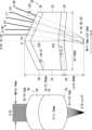
図1は、比較例にかかる光偏向デバイス1Aを示す図である。また、図2は、比較例にかかる光偏向デバイス1Aを側面方向から見た側面図である。また、図3は、比較例にかかる光偏向デバイス1Aを正面方向から見た正面図である。(Summary of this embodiment)
DESCRIPTION OF THE PREFERRED EMBODIMENTS An overview of embodiments of the present invention will be described below with reference to the drawings.
FIG. 1 is a diagram showing an
光偏向デバイス1Aは、フォトニック結晶導波路2と、シリンドリカルレンズ10とを有する。シリンドリカルレンズ10は、フォトニック結晶導波路2の上方(フォトニック結晶導波路2から光が放射される側)に設けられている。フォトニック結晶導波路2の構成は、上述した特許文献1にかかるフォトニック結晶導波路の構成と実質的に同様であるので、概要のみ説明する。フォトニック結晶導波路2は、回折格子4と導波路6とを有する。回折格子4は、Si等の半導体からなる高屈折率部材に低屈折率部位を周期的に配することで形成されている。導波路6は、光が入射方向(正面方向)から入射されることで光を伝搬する。 The
ここで、光の導波路6への入射方向をX軸方向とし、鉛直上方(真上方向)をZ軸方向とする。また、ZX平面に垂直な方向をY軸方向(側面方向)とする。また、正面方向から見て左右方向に振れる角度をΦ(Φ方向)とする。つまり、Φ方向は、YZ平面上の方向である。また、側面方向から見て左右方向に振れる角度をθ(θ方向)とする。つまり、θ方向は、ZX平面上の方向である。フォトニック結晶導波路2は、θ方向には、光の波長やフォトニック結晶導波路2(回折格子4)の屈折率を変えることで光を偏向し、Φ方向には、導波路6を切り替えてシリンドリカルレンズ10との相対位置を変えることで光を偏向する。 Here, the direction of incidence of light into the
導波路6は、回折格子4が設けられていない部分により、X軸方向(正面方向から見て奥行方向)に沿って形成されている。導波路6に入射された光は、導波路6をX軸方向に伝搬しながら、導波路6の上方(Z軸方向)に放射される。このとき、図2に示すように、導波路6の上方に放射される光(放射光Lr)は、Z軸方向に対して、伝搬方向(X軸方向)に角度θだけ傾いて放射される。また、図3に示すように、導波路6の幅が狭いため、導波路6から放射される放射光Lrは、光伝搬方向(X軸方向)から見たときに、横方向(Y軸方向)に扇状に角度±Φaで広がるビームとなる。 The
シリンドリカルレンズ10は、図2に示すように、導波路6に沿った方向(伝搬方向つまりX軸方向)には一様の形状に形成されている。言い換えると、シリンドリカルレンズ10は、側面方向から見たZX断面において略長方形となるように形成されている。さらに言い換えると、シリンドリカルレンズ10をY軸に垂直な平面で切断したとき、上面10aは曲線とならない。一方、シリンドリカルレンズ10は、図3に示すように、導波路6に沿った方向(伝搬方向つまりX軸方向)に直交する方向(Y軸方向)には上面10aが上方に湾曲するように形成されている。言い換えると、シリンドリカルレンズ10は、正面方向から見たZY断面において上面10aが上に凸となるように形成されている。さらに言い換えると、シリンドリカルレンズ10をX軸に垂直な平面で切断したとき、上面10aは上に凸の曲線となる。なお、シリンドリカルレンズ10の形状は、上面10aが上に凸である必要はなく、下に凸又は両側に凸となるように形成されてもよい。 As shown in FIG. 2, the
シリンドリカルレンズ10がこのように形成されていることによって、放射光LrのΦ方向の広がりが抑制される。言い換えると、シリンドリカルレンズ10によって、放射光Lrがコリメートされ、平行光(コリメートビーム)に変換される。これにより、Z軸方向の遠方に平行光である放射光Lrが照射される。ここで、導波路6からの放射光Lrの放射角度θについて、ある特定のθ方向の放射角度(θa)の放射(図2参照)に対して放射光Lrがコリメートされるように、シリンドリカルレンズ10の位置が調整されているとする。なお、本明細書において、用語「コリメート」は、放射光を厳密に平行にすることに限定されない。出射光の広がりが許容範囲内の角度(例えば0.01°~0.1°程度)に抑制されていれば、光が「コリメート」されているといえる。 By forming the
次に、図1に示した光偏向デバイス1Aの問題点について説明する。
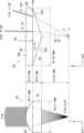
図4~図6は、図1に示した光偏向デバイス1Aの第1の問題点を説明するための図である。上述したように、角度θaの放射に対して放射光Lrがコリメートされるようにシリンドリカルレンズ10の位置が調整されているとする。この場合において、放射角度θを図2における放射角度θaよりも大きいθbに変更したとする。このとき、導波路6からシリンドリカルレンズ10までの距離(光路長)が、LaからLbに長くなる。Next, problems with the
4 to 6 are diagrams for explaining the first problem of the
一方、放射角度θを大きくすると、放射光Lrは、シリンドリカルレンズ10の上面10aに対して、斜めとなった方向で交差するので、放射光Lrの進行方向に対する上面10aの曲率半径が小さくなる。なお、このことは、円柱をある平面で切断するときの切断面について、円柱の中心軸に垂直な平面で切断した切断面の曲率半径は底面の円の半径と等しいが、円柱の中心軸に垂直な平面から傾いた平面で切断した切断面の曲率半径は、底面の円の半径よりも小さくなることからも明らかである。 On the other hand, when the radiation angle θ is increased, the radiation light Lr intersects the
このように、曲率半径が小さくなると、焦点距離が短くなり、焦点がずれる。つまり、放射光Lrをコリメートできる条件がずれてしまうので、図5に示すように、シリンドリカルレンズ10を通過しても、放射光Lrはコリメートされなくなる。さらに、焦点距離が短くなるにも関わらず、上述したように放射角度θaが大きくなると導波路6からシリンドリカルレンズ10までの距離が長くなるので、焦点がさらにずれ、放射光Lrをコリメートする条件はさらに悪化する。これにより、図5に示すように、鉛直上方(Z軸方向)に対する、シリンドリカルレンズ10から出射した放射光Lrの広がり角度Φ’は、0°から離れてしまう。 In this way, when the radius of curvature becomes smaller, the focal length becomes shorter and the focus shifts. In other words, the conditions under which the radiation light Lr can be collimated are shifted, so that the radiation light Lr is no longer collimated even if it passes through the
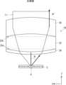
図6は、導波路6からの光の放射角度θを偏向したときのΦ方向のコリメート状況を示す遠視野像を例示する図である。図6に示す例では、θ=23°のときにコリメートされるように条件を設定している。この場合、θが23°から離れるに従って、広がり角度Φ’が0°から離れる。このように、図1に示した光偏向デバイス1Aは、放射角度θを変更するとシリンドリカルレンズ10の焦点がずれてしまうので、幅広い放射角度θに対して放射光Lrをコリメートさせることが困難である。 FIG. 6 is a diagram illustrating a far-field image showing the state of collimation in the Φ direction when the light from the
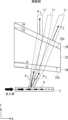
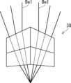
図7~図8は、図1に示した光偏向デバイス1Aの第2の問題点を説明するための図である。図7に示すように、フォトニック結晶導波路2に対する光の入射方向を切り替えると、±θ方向に光が偏向される。具体的には、X軸の正方向へ光を入射すると、+θ方向へ光が偏向される。一方、X軸の負方向へ光を入射すると、-θ方向へ光が偏向される。これにより、光の波長やフォトニック結晶導波路2の屈折率を変えてθを偏向させることに加え、光の入射方向を左右で切り替えれば,θ方向の光の偏向範囲を2倍に拡大できる。ここで、上述したように、フォトニック結晶導波路2は、光を真上方向(出射角度θ’=0°)に放射することができない。 7 to 8 are diagrams for explaining the second problem of the
図8は、左右切り替えスイッチと熱光学効果によってθ方向に、導波路6の切り替えによってΦ方向に光偏向を行ったときのビームの遠視野像を例示する図である。ただし各スポットに対してレンズの焦点距離を微調整しているので、上述した第1の問題点は露わには見えない。ここで、図8で明らかなように、θ=0°近傍のビームの遠視野像が観測されない。図8では、-5°<θ<5°の範囲のビームが観測されないが、実際に有効に使用できるのは、-10°<θ<10°の範囲を除くビームとなる。また、シリンドリカルレンズ10は、フォトニック結晶導波路2から放射された光の、導波路6に沿った方向に対する左右方向(Φ方向)の広がりを抑制するのみであって、導波路6から放射された斜め方向の光を真上方向(θ’=0°)に偏向することは困難である。このように、図1に示した光偏向デバイス1Aは、導波路6から放射された斜め方向の光を真上方向(出射角度θ’=0°)の近傍の方向の光に偏向することが困難である。 FIG. 8 is a diagram illustrating a far-field image of a beam when light is deflected in the θ direction by the left/right switch and the thermo-optic effect, and in the Φ direction by switching the
これに対し、本実施の形態にかかる光偏向デバイスは、以下に説明するように、上述した第1の問題点及び第2の問題点を解決することができる。具体的には、シリンドリカルレンズ10の代わりに、互いに平行でない対向する1組の面の少なくとも一方に一体に形成されたシリンドリカルレンズを有するプリズムレンズを採用することで、上記の問題を解決できる。ここで、「互いに平行でない対向する1組の面」とは、一端から他端に向かって互いの間隔が短く又は長くなる、対向する1組の面である。 In contrast, the optical deflection device according to the present embodiment can solve the first problem and the second problem described above, as described below. Specifically, the above problem can be solved by employing a prism lens having a cylindrical lens integrally formed on at least one of a pair of opposing surfaces that are not parallel to each other, instead of the
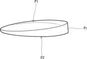
図9は、一般的なプリズムレンズPrの例を示す図である。プリズムレンズは、厚みが傾斜するように形成されている。したがって、プリズムレンズは、互いに平行でない対向する1組の面P1,P2を有する。つまり、面P1及び面P2は、これらの一端から他端に向かって互いの間隔が短く又は長くなる、対向する1組の面である。例えば、図9において、左端から右端に向かって、面P1と面P2との間隔は長くなる。逆に、図9において、右端から左端に向かって、面P1と面P2との間隔は短くなる。光がプリズムレンズPrを通過することにより、光の進行方向が屈折する。本実施の形態では、プリズムレンズのこの性質が利用されている。 FIG. 9 is a diagram showing an example of a general prism lens Pr. The prism lens is formed to have a sloped thickness. Therefore, the prism lens has a pair of opposing surfaces P1, P2 that are not parallel to each other. In other words, the surfaces P1 and P2 are a pair of opposing surfaces in which the distance between them becomes shorter or longer from one end to the other end. For example, in FIG. 9, the distance between the planes P1 and P2 increases from the left end to the right end. Conversely, in FIG. 9, the distance between the planes P1 and P2 becomes shorter from the right end to the left end. When the light passes through the prism lens Pr, the traveling direction of the light is refracted. In this embodiment, this property of the prism lens is utilized.
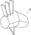
(実施の形態1)
図10は、実施の形態1にかかる光偏向デバイス1を示す斜視図である。また、図11は、実施の形態1にかかる光偏向デバイス1を示す側面図である。実施の形態1にかかる光偏向デバイス1は、フォトニック結晶導波路2と、プリズムレンズ20とを有する。フォトニック結晶導波路2は、高屈折率部材に低屈折率部位を周期的に配列されて形成された回折格子付きの導波路であって、図1に示したものと実質的に同様である。(Embodiment 1)
FIG. 10 is a perspective view showing the
プリズムレンズ20は、プリズムレンズ本体22と、シリンドリカルレンズ24,26とを有する。プリズムレンズ本体22は、互いに平行でない対向する1組の面22a,22b(第1の面)を有する。ここで、プリズムレンズ本体22の下方(フォトニック結晶導波路2の側)の面が面22aであり、上方(フォトニック結晶導波路2の反対側)の面が面22bである。したがって、面22a,22bは、これらの一端から他端に向かって互いの間隔が短く又は長くなる、対向する1組の面である。例えば、図11において、左端から右端(X軸の正方向)に向かって、面22aと面22bとの間隔は短くなる。逆に、図9において、右端から左端(X軸の負方向)に向かって、面22aと面22bとの間隔は長くなる。プリズムレンズ20は、光の伝搬方向であるX軸方向について、面22a,面22bのX軸の正方向の側(光の入射方向の下流側)がフォトニック結晶導波路2に近づくように傾くように、設置されている。ここで、面22a及び面22bは、ZX平面に垂直であるとする。したがって、プリズムレンズ本体22は、側面方向(Y軸方向)から見た面(図10の矢印Aで示す)を底面とする四角柱であるといえる。しかしながら、プリズムレンズ本体22の形状は、四角柱であることに限定されない。また、プリズムレンズ本体22は、面22aと面22bとの距離が、X軸の正方向の側(光の入射方向の下流側)の方がX軸の負方向の側(光の入射方向の上流側)よりも近くなるように形成されている。 The
シリンドリカルレンズ24は、面22a(第1の面)に一体に形成されている。シリンドリカルレンズ26は、面22b(第1の面)に一体に形成されている。したがって、プリズムレンズ20は、互いに平行でない対向する1組の面22a,22bにシリンドリカルレンズ24,26が形成されるように構成されている。なお、シリンドリカルレンズ24は面22aに一体に形成されているので、プリズムレンズ本体22とシリンドリカルレンズ24との境界は、プリズムレンズ20の切断等により視覚的に確認できる必要はない。同様に、シリンドリカルレンズ26は面22bに一体に形成されているので、プリズムレンズ本体22とシリンドリカルレンズ26との境界は、プリズムレンズ20の切断等により視覚的に確認できる必要はない。 The
ここで、シリンドリカルレンズ24は、面22aの面22b(プリズムレンズ本体22の1組の面のうちの他方の面)に対する傾き方向(図11の矢印Aで示す)に対して垂直な平面Paにおける断面形状が、面22aに対して凸となるような一定の曲線形状を有するように、形成されている。つまり、シリンドリカルレンズ24は、矢印Aで示す傾き方向に、一様の形状に形成されている。したがって、シリンドリカルレンズ24の稜線24aは、面22aと平行である。なお、矢印Aで示す傾き方向は、ZX平面に略平行である。また、矢印Aで示す傾き方向は、面22aを含む平面と面22bを含む平面とが交差して得られた交線に略垂直である。 Here, the
また、シリンドリカルレンズ26は、面22bの面22a(プリズムレンズ本体22の1組の面のうちの他方の面)に対する傾き方向(図11の矢印Bで示す)に対して垂直な平面Pbにおける断面形状が、面22bに対して凸となるような一定の曲線形状を有するように、形成されている。つまり、シリンドリカルレンズ26は、矢印Bで示す傾き方向に、一様の形状に形成されている。したがって、シリンドリカルレンズ26の稜線26aは、面22bと平行である。なお、矢印Bで示す傾き方向は、ZX平面に略平行である。また、矢印Bで示す傾き方向は、面22aを含む平面と面22bを含む平面とが交差して得られた交線に略垂直である。 Further, the
プリズムレンズ20は、上述のように形成されていることによって、側面方向から見ると、光を屈折させるプリズムとして機能し、正面方向から見ると、2つのシリンドリカルレンズ24,26を組み合わせたレンズとして機能する。したがって、上述のように形成されたプリズムレンズ20を用いることによって、放射角度θが変更されても放射光Lrをコリメートさせる(放射光Lrの広がりを抑制させる)ことが可能となる(第1の問題点の解決)。さらに、上述のように形成されたプリズムレンズ20を用いることによって、導波路6から放射された斜め方向の光を真上方向(出射角度θ’=0°)の近傍の方向の光に偏向することが可能となる(第2の問題点の解決)。 By being formed as described above, the
図12~図14は、実施の形態1にかかるプリズムレンズ20の作用を説明するための図である。図12は、放射角度θが変更されても放射光Lrをコリメートさせることができる原理を説明するための図である。図12は、図11に示したプリズムレンズ20の右側を上側に回転させた図であり、説明の明確化のため、プリズムレンズ20(プリズムレンズ本体22)が左右対称となるような角度となるように描画されている。 12 to 14 are diagrams for explaining the action of the
図12において、紙面の左方向から水平よりやや上向きに光線をプリズムレンズ20に入射したとき、プリズムレンズ20内で光線の方向が真横になり、右側から、左側の光線の方向と対称となるようなやや下向きの光線が出射する状況を考える。ここで、入射角をθ0とすると、出射角は-θ0となる。また、シリンドリカルレンズ24の曲率をR1-1(曲率半径R1)とし、シリンドリカルレンズ26の曲率をR2-1(曲率半径R2)とし、これらが等しいとする(R1-1=R2-1)。また、光源からレンズまでの長さ(光路長に対応する長さ)をL1とし、レンズ中の長さ(光路長に対応する長さ)をL2とする。この場合、2つのレンズを組み合わせてΦ方向(紙面奥行き方向)に広がる光をコリメートする系が成立し得ることが理解される。つまり、入射角の絶対値と出射角の絶対値とが等しく、シリンドリカルレンズ24の曲率とシリンドリカルレンズ26の曲率とが等しいので、光線の入射した方向における曲率半径は、光線が出射した方向における曲率半径と等しい(この曲率半径をR’とする)。したがって、このときの光源の位置がプリズムレンズ20のシリンドリカルレンズ24の側の焦点に一致するように長さL1を設定することで、シリンドリカルレンズ26から出射する光線はコリメートされ得る。In FIG. 12, when a light ray enters the
次に、入射角がθ0+Δθとなる条件を考える。このとき、光源からレンズまでの長さL1は、θ0の場合と比較してやや長くなり、レンズ中の長さL2は、θ0の場合と比較してやや短くなるので、両者が相殺する方向に働く。また、シリンドリカルレンズ24に入射する角度がやや大きくなるので、このシリンドリカルレンズ24に入射する方向に対する曲率は、θ0の場合と比較して大きくなる(曲率半径がR’よりも小さくなる)。逆に、シリンドリカルレンズ26に入る角度はやや小さくなるので、シリンドリカルレンズ26に入射する方向に対する曲率は小さくなる(曲率半径がR’よりも大きくなる)。したがって、曲率(曲率半径)についても両者が相殺する方向に働く。したがって、焦点のずれが抑制されるので、結果的に、θ0のときのコリメート条件が維持される。同様のことはθ0-Δθの場合にも当てはまるので、いずれの方向に入射角を変更したとしても、焦点のずれが抑制されるので、θ0のときのコリメート条件が維持される。つまり、θ0の場合の光源の位置を焦点と一致させておくと、θ0±Δθの場合でも、光源の位置が焦点と略一致する。Next, consider the conditions under which the incident angle is θ0 +Δθ. At this time, the length L1 from the light source to the lens is slightly longer than when θis 0 , and the length L2 inside the lens is slightly shorter than when θis 0 , so the two cancel each other out. Work in the direction. Furthermore, since the angle of incidence on the
ただし、このコリメート条件を満たすΔθには範囲がある。図12でθ0+Δθのとき、シリンドリカルレンズ26に入る光の角度は垂直に近くなる。この角度が垂直を超えると、再び曲率は大きくなり始めるので、上記の相殺が起こらなくなる。一方、θ0-Δθでは、シリンドリカルレンズ24に入る光の角度が垂直より下向きになると、相殺が起こらなくなる。よって、2Δθは、プリズムレンズ本体22の二つの面22a,22bが成す角度よりも小さい必要がある。However, there is a range of Δθ that satisfies this collimation condition. In FIG. 12, when θ0 +Δθ, the angle of light entering the
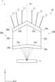
図13は、導波路6から光を放射する際の放射角度θが変更された場合の放射光Lrを示す側面図である。また、図14は、導波路6から光を放射する際の放射角度θが変更された場合の放射光Lrを示す正面図である。図13に示すように、θがθ1~θ2に変化するとする。そして、導波路6からの光の放射角度がθ1の際の、プリズムレンズ20からの光の出射角度をθ1’とする。また、導波路6からの光の放射角度がθ2の際の、プリズムレンズ20からの光の出射角度をθ2’とする。ここで、図13に示すように、面22aがXY平面(導波路6)と成す傾斜角をΘとし、面22bがXY平面(導波路6)と成す傾斜角をΘ’とする。このとき、傾斜角Θ及び傾斜角Θ’を調整することで、プリズムの作用により、放射角度θ1の際に、θ1’=0とすることができる。したがって、実施の形態1にかかるプリズムレンズ20は、上述した第2の問題点を解決することが可能となる。つまり、実施の形態1にかかるプリズムレンズ20は、導波路6から放射された斜め方向の放射光を真上方向(出射角度θ’=0°)の光に偏向することが可能となる。FIG. 13 is a side view showing the emitted light Lr when the radiation angle θ when emitting light from the
また、図14に示すように、導波路6からの放射角度θがθ1~θ2に変更されたとしても、図12を用いて上述したように、焦点のずれが抑制されるので、放射光Lrをコリメートすることが可能となる。具体的には、図13から分かるように、放射角度θが小さいと放射光Lrはシリンドリカルレンズ24に略垂直に入射し、放射角度θが大きくなるにつれて、放射光Lrがシリンドリカルレンズ24に入射する角度は小さく(90°から遠く)なっていく。したがって、放射角度θが大きくなるにつれて、シリンドリカルレンズ24の放射光Lrの入射方向に対する曲率半径は小さくなる。これに対し、放射角度θが大きいと放射光Lrはシリンドリカルレンズ26に略垂直に入射し、放射角度θが小さくなるにつれて、放射光Lrがシリンドリカルレンズ26に入射する角度は小さく(90°から遠く)なっていく。したがって、放射角度θが大きくなるにつれて、シリンドリカルレンズ26の放射光Lrの入射方向に対する曲率半径は大きくなる。また、図13から分かるように、放射角度θが大きくなるにつれて、導波路6からシリンドリカルレンズ24までの光路長L1は長くなるが、プリズムレンズ20内における光路長L2は短くなる。これにより、放射角度θが変更されても、焦点のずれが抑制される。Furthermore, as shown in FIG. 14, even if the radiation angle θ from the
つまり、図12を用いて上述した条件が成り立つので、正面方向から見た横方向の、放射光Lr(出射ビーム)の広がり角度Φ’を0°近傍に抑制することが可能となる。したがって、実施の形態1にかかるプリズムレンズ20は、上述した第1の問題点を解決することが可能となる。言い換えると、実施の形態1にかかるプリズムレンズ20は、幅広い放射角度θに対して放射光Lrの広がり角度Φ’の増大を抑制することが可能となる。 In other words, since the conditions described above with reference to FIG. 12 hold, it is possible to suppress the spread angle Φ' of the emitted light Lr (outgoing beam) in the lateral direction when viewed from the front direction to around 0°. Therefore, the
ここで、焦点のずれが抑制されることについて、数式を用いて概略的に説明する。ある放射角度θ0で出射ビームがコリメートされるように設定されているとする。また、ある放射角度θで光が放射されたときの、シリンドリカルレンズ24に入射する方向に対するシリンドリカルレンズ24における曲率半径をr1(≦R1)とし、シリンドリカルレンズ26に入射する方向に対する曲率半径をr2(≦R2)とする。また、このときの光源からレンズまでの長さをL1とし、レンズ中の長さをL2とする。このとき、レンズメーカーの式は、以下の式(1)のように表される。但し、fは焦点距離であり、nはプリズムレンズ20の屈折率である。

式(1)及び式(2)から、r1=r2=r0としたとき、L1は、以下の式(3),(4)のように表される。

式(3)、(4)を満たせば、光はコリメートされ得る。From equations (1) and (2), when r1 =r2 =r0 , L1 is expressed as in equations (3) and (4) below.
Light can be collimated if equations (3) and (4) are satisfied.
放射角度θが大きくなると(図13のθ1→θ2)、光源からプリズムレンズ20までの長さL1は長くなり、シリンドリカルレンズ24におけるr1は小さくなり、レンズ中を光が伝搬する長さL2は短くなり、シリンドリカルレンズ26におけるr2は大きくなる。この状況を、r1、r2、L1、L2がそれぞれr1-Δr1、r2+Δr2、L1+ΔL1、L2-ΔL2に変化したと考える。ここで、Δが付いたパラメータが微小であると仮定する。また、ここでもr1=r2=r0とおき、r1≒r0-Δr、r2≒r0+Δrと近似する。以上のパラメータの変化を式(1)、(2)に代入し、さらにΔが付いたパラメータの二乗以上の高次の項は十分に小さいとして削除すると、最終的に以下の式(5)で示される近似式が得られる。

ここでL1、ΔL1、L2、ΔL2、Δr、Aは、いずれも図13における光の放射角度θ、プリズムレンズ20の上下の角度Θ、Θ’、プリズムレンズ20の屈折率n、プリズムレンズ20のZ軸方向の厚さ、光源からプリズムレンズ20までの距離で表現することができる。したがって、それらを式(6)に代入すれば、これらの構造パラメータに対する条件を導くことができる。ここで、屈折率n、ならびにフォトニック結晶導波路2からの光の放射角の範囲θ1~θ2を固定値とし、θ1~θ2の中の代表的な角度を図12のような対称的な光線軌跡を示すθ0と定めると、これに対して、第2の問題点を解決するためのΘとΘ’が定まる。これを上記の構造パラメータに対する条件に適用すれば、プリズムレンズ20のZ軸方向の厚さ、および光源からプリズムレンズ20までの距離を、r0の定数倍として与えることができる。Here, L1 , ΔL1 , L2 , ΔL2 , Δr, and A are all the radiation angle θ of light in FIG. It can be expressed by the thickness of the
(実施の形態2)
次に、実施の形態2について説明する。
図15は、実施の形態2にかかる光偏向デバイス1を示す斜視図である。また、図16は、実施の形態2にかかる光偏向デバイス1を示す側面図である。実施の形態1にかかる光偏向デバイス1は、フォトニック結晶導波路2と、プリズムレンズ30とを有する。実施の形態2にかかるプリズムレンズ30は、実施の形態1にかかるプリズムレンズ20を2つ組み合わせた(結合させた)ように形成されている。(Embodiment 2)
Next, a second embodiment will be described.
FIG. 15 is a perspective view showing the
具体的には、プリズムレンズ30は、プリズムレンズ20のYZ平面に略平行な2つの面のうち面積の広い方(面22aと面22bとの間の距離が長い方)の面を互いに結合したように形成されている。これにより、プリズムレンズ30は、X軸方向の中央近傍で屈曲したような形状を有している。つまり、実施の形態2にかかるプリズムレンズ30は、プリズムレンズ本体22の面22a,22bの傾斜方向がそれぞれ対称となるように、シリンドリカルレンズ24,26が形成されたプリズムレンズ本体22が組み合わされるように形成されている。 Specifically, the
プリズムレンズ30は、プリズムレンズ20Aとプリズムレンズ20Bとで形成されている。プリズムレンズ20A及びプリズムレンズ20Bは、実施の形態1にかかるプリズムレンズ20と実質的に同様の形状を有している。したがって、プリズムレンズ20Aは、プリズムレンズ本体22Aと、シリンドリカルレンズ24Aと、シリンドリカルレンズ26Aとを有する。プリズムレンズ20Bは、プリズムレンズ本体22Bと、シリンドリカルレンズ24Bと、シリンドリカルレンズ26Bとを有する。プリズムレンズ本体22A,22Bは、プリズムレンズ本体22に対応する。シリンドリカルレンズ24A,24Bは、シリンドリカルレンズ24に対応する。シリンドリカルレンズ26A,26Bは、シリンドリカルレンズ26に対応する。 The
シリンドリカルレンズ24Aは、プリズムレンズ本体22Aの面22aに一体に形成されている。シリンドリカルレンズ26Aは、プリズムレンズ本体22Aの面22bに一体に形成されている。シリンドリカルレンズ24Bは、プリズムレンズ本体22Bの面22aに一体に形成されている。シリンドリカルレンズ26Bは、プリズムレンズ本体22Bの面22bに一体に形成されている。ここで、プリズムレンズ本体22Aの面22aの傾斜方向とプリズムレンズ本体22Bの面22aの傾斜方向とが、プリズムレンズ20Aとプリズムレンズ20Bとの境界面Pcについて対称となっている。同様に、プリズムレンズ本体22Aの面22bの傾斜方向とプリズムレンズ本体22Bの面22bの傾斜方向とが、プリズムレンズ20Aとプリズムレンズ20Bとの境界面Pcについて対称となっている。 The
図17は、実施の形態2にかかるプリズムレンズ30により放射光Lrが偏向された状態を示す図である。矢印Aで示す方向から光を入射すると、導波路6から+θ方向に光が放射される。そして、上述したように、放射光Lrは、ある放射角度θのときに、出射角度θ’=0で出射される。そして、矢印Aとは逆方向の矢印Bで示す方向から光を入射すると、導波路6から、+θ方向とは逆方向(負方向)の-θ方向に光が放射される。そして、上述したように、放射光Lrは、ある放射角度θのときに、出射角度θ’=0で出射される。したがって、放射角度θを-θ2~+θ2とした場合(図13参照)に、放射光Lrを、-θ2~0°~+θ2に連続的に偏向することができる。つまり、実施の形態2にかかるプリズムレンズ30を採用することにより、出射角度θ’が0°近傍の正負方向となるように、放射光Lrを偏向することが可能となる。FIG. 17 is a diagram showing a state in which the radiation light Lr is deflected by the
図18は、実施の形態2にかかるプリズムレンズ30により放射光Lrがコリメートされた状態を示す正面図である。上述したように、実施の形態2にかかるプリズムレンズ30は、実施の形態1にかかるプリズムレンズ20を組み合わせたものであるので、実施の形態1にかかるプリズムレンズ20と同様に、放射光Lrをコリメートすることが可能となる。つまり、正面方向から見た横方向の、放射光Lr(出射ビーム)の広がり角度Φ’を0°近傍に抑制することが可能となる。そして、実施の形態2にかかるプリズムレンズ30は、放射角度θが正方向(+θ)及び負方向(-θ)のいずれの場合であっても、放射光Lrをコリメートすることが可能となる。 FIG. 18 is a front view showing a state in which the emitted light Lr is collimated by the
図19は、実施の形態2にかかるプリズムレンズ30の第1の設計例を示す図である。図19の左図はプリズムレンズ30の正面図であり、図19の右図はプリズムレンズ30の側面図である。なお、図19においては、プリズムレンズ本体22Aとプリズムレンズ本体22Bとを区別しない。したがって、プリズムレンズ30のプリズムレンズ本体22A,22Bをプリズムレンズ本体22と表記し、シリンドリカルレンズ24A,24Bをシリンドリカルレンズ24と表記し、シリンドリカルレンズ26A,26Bをシリンドリカルレンズ26と表記する。 FIG. 19 is a diagram showing a first design example of the
プリズムレンズ30の屈折率をn=1.5とする。また、面22aの傾斜角をΘ=5.5°とし、面22bの傾斜角をΘ’=24.6°とする。また、シリンドリカルレンズ24の曲率半径をR1=10.2mmとし、シリンドリカルレンズ26の曲率半径をR2=10.2mmとする。また、プリズムレンズ30の焦点距離をf=11.38mmとする。また、プリズムレンズ30の全体の長さ(X軸方向の長さ)をD1=16mmとし、中央における高さをH1=12.88mmとする。また、導波路6からプリズムレンズ30の中央までの距離をL0=6.86mmとする。また、導波路6の放射開口幅をW0=1.0mmとし、X=0を中心として±0.5mmとする。また、放射角度θを10,20,30°とする。また、放射広がり角をδΦ=±15°(=30°)とする。上記の条件において、シミュレーションを行った。It is assumed that the refractive index of the
このとき、出射光のビーム幅はWb=6.1mmとなる。θ=10°の場合の放射開口幅の負側端部における出射角度θ’は0°となる。また、θ=30°の場合の放射開口幅の正側端部における出射角度θ’は20°となる。また、広がり角Φの分布の半値全幅(半値幅)をδΦ’とすると、θ=10,20,30°の場合の放射開口幅の負側端部における半値全幅は、それぞれ、δΦ’=0.10,0.01,0.10°となる。同様に、θ=10,20,30°の場合の放射開口幅の正側端部における半値全幅は、それぞれ、δΦ’=0.04,0.11,0.04°となる。ここで、図1に示したシリンドリカルレンズ10を用いた場合、δΦ’=0.8°程度となるので、本実施の形態にかかるプリズムレンズを用いることで、出射ビームが良好にコリメートされていることが分かる。 At this time, the beam width of the emitted light is Wb=6.1 mm. When θ=10°, the emission angle θ' at the negative end of the radiation aperture width is 0°. Furthermore, when θ=30°, the emission angle θ' at the positive end of the radiation aperture width is 20°. Furthermore, if the full width at half maximum (half width) of the distribution of the spread angle Φ is δΦ', the full width at half maximum at the negative end of the radiation aperture width when θ = 10, 20, and 30° is δΦ' = 0, respectively. .10, 0.01, 0.10°. Similarly, the full width at half maximum at the positive end of the radiation aperture width when θ=10, 20, and 30° is δΦ′=0.04, 0.11, and 0.04°, respectively. Here, when the
なお、本実施の形態におけるプリズムレンズは、光の伝搬方向(X軸方向)に沿った方向で形状が変化するように形成されている。一方、図19に示すように、導波路6の放射開口幅(導波路長)が1.0mm程度であるとすると、光源の位置がこの放射開口幅の範囲のいずれかとなる。したがって、光源の位置によっては、コリメート条件が満たされない可能性はある(上述したように、図19において、放射開口幅の正側端部からの放射光と負側端部からの放射光とで、出射ビームの広がり角度Φ’(半値全幅δΦ’)が異なることからも明らかである)。このことは、プリズムレンズのサイズが導波路長に近い場合に顕著となり得る。一方、導波路長と比較してプリズムレンズのサイズを十分大きくし、光源とプリズムレンズとの距離を長くすることで、光源を1点と近似することができる。これにより、放射角度θによらないでコリメート条件が満たされる可能性はより高くなる。 Note that the prism lens in this embodiment is formed so that its shape changes in the direction along the light propagation direction (X-axis direction). On the other hand, as shown in FIG. 19, if the radiation aperture width (waveguide length) of the
図20は、実施の形態2にかかるプリズムレンズ30の第2の設計例を示す図である。図20の左図はプリズムレンズ30の正面図であり、図20の右図はプリズムレンズ30の側面図である。なお、図19の例と同様に、図20においては、プリズムレンズ本体22Aとプリズムレンズ本体22Bとを区別しない。さらに、図20においては、プリズムレンズ本体22の面22a,22bは明示されていない。 FIG. 20 is a diagram showing a second design example of the
プリズムレンズ30の屈折率をn=1.5とする。また、面22aの傾斜角(シリンドリカルレンズ24の稜線の傾斜角)をΘ=5.5°とし、面22bの傾斜角(シリンドリカルレンズ26の稜線の傾斜角)をΘ’=24.6°とする。また、シリンドリカルレンズ24の曲率半径をR1=12.75mmとし、シリンドリカルレンズ26の曲率半径をR2=12.75mmとする。また、プリズムレンズ30の焦点距離をf=12.93mmとする。また、プリズムレンズ30の全体の長さ(X軸方向の長さ)をD1=23mmとし、中央における高さをH1=17.63mmとする。また、プリズムレンズ30の幅方向の長さ(Y軸方向の長さ)をD2=24mmとする。また、プリズムレンズ30の最底部と導波路6との高低差をH0=7.72mmとする。また、プリズムレンズ30の最高部と最底部との高低差をH2=18.73mmとする。また、導波路6からプリズムレンズ30の中央までの距離をL0=8.82mmとする。また、導波路6の放射開口幅をW0=1.0mmとし、X=0を中心として±0.5mmとする。また、放射角度θを10,20,30°とする。また、放射広がり角をδΦ=±15°(=30°)とする。上記の条件において、シミュレーションを行った。この場合、図20に示すように、放射角度がθ=10°のときに、出射角度θ’=0を実現できていることが分かる。It is assumed that the refractive index of the
図21~図24は、図20に示したプリズムレンズ30の第2の設計例において、様々な角度で光を放射した場合のシミュレーション結果を示す図である。図21及び図22は、導波路6の単一の放射位置から、様々な角度で、両方向(放射角度θの正方向(+θ)及び負方向(-θ))へ光を放射した場合のシミュレーション結果を示す。図21はプリズムレンズ30の斜視図であり、図22はプリズムレンズ30の側面図である。図21に示すように、様々な角度で光を放射した場合であっても、第2の設計例にかかるプリズムレンズ30を用いることで、出射ビームがコリメートされていることが分かる。また、図22で示すように、第2の設計例にかかるプリズムレンズ30を用いることで、矢印Be1で示す出射ビームが、真上方向(θ’=0)に出射されていることが分かる。 21 to 24 are diagrams showing simulation results when light is emitted at various angles in the second design example of the
図23及び図24は、導波路6の複数の放射位置から、様々な角度で、片方向(放射角度θの負方向(-θ))へ光を放射した場合のシミュレーション結果を示す。図23はプリズムレンズ30の斜視図であり、図24はプリズムレンズ30の側面図である。図23に示すように、様々な角度で光を放射した場合であっても、第2の設計例にかかるプリズムレンズ30を用いることで、出射ビームがコリメートされていることが分かる。また、図24で示すように、第2の設計例にかかるプリズムレンズ30を用いることで、矢印Be2で示す出射ビームが、真上方向(θ’=0)に出射されていることが分かる。 23 and 24 show simulation results when light is emitted from a plurality of emission positions of the
図25は、図20に示したプリズムレンズ30の第2の設計例における、出射ビームの広がり角度Φ’の計算例を示す図である。図25は、放射位置X=-0.5,0,+0.5mmから、放射角度θ=10,16,24,30°で光を放射した場合の、出射ビームの広がり角度Φ’を示す。いずれの図においても、広がり角度Φ’の分布の中心を0°として描かれているが、半値全幅は±0.01~0.08°の範囲である。したがって、図20に示したプリズムレンズ30の第2の設計例では、放射角度θ=10,16,24,30°で光を放射した場合に、良好に出射ビームがコリメートされていることが分かる。 FIG. 25 is a diagram showing an example of calculating the spread angle Φ' of the emitted beam in the second design example of the
(実施の形態3)
次に、実施の形態3について説明する。上述した実施の形態1等では、プリズムレンズ本体の互いに平行でない対向する1組の面の両側の面に、シリンドリカルレンズが形成されている。これに対し、実施の形態3においては、プリズムレンズ本体の互いに平行でない対向する1組の面の片方の面にシリンドリカルレンズが形成されている点で、実施の形態1等とは異なる。(Embodiment 3)
Next, Embodiment 3 will be described. In the first embodiment and the like described above, cylindrical lenses are formed on both sides of a pair of opposing surfaces that are not parallel to each other of the prism lens body. In contrast, the third embodiment differs from the first embodiment in that a cylindrical lens is formed on one of a pair of opposing surfaces that are not parallel to each other of the prism lens body.
図26は、実施の形態3にかかるプリズムレンズ50を示す図である。図26の左図はプリズムレンズ50の正面図であり、図26の右図はプリズムレンズ50の側面図である。実施の形態3にかかるプリズムレンズ50は、プリズムレンズ本体52と、シリンドリカルレンズ56とを有する。プリズムレンズ本体52は、互いに平行でない対向する1組の面52a,52b(第1の面)を有する。ここで、プリズムレンズ本体52の下方(フォトニック結晶導波路2の側)の面が面52aであり、上方(フォトニック結晶導波路2の反対側)の面が面52bである。したがって、面52a,52bは、これらの一端から他端に向かって互いの間隔が短く又は長くなる、対向する1組の面である。例えば、図26の右図において、左端から右端(X軸の正方向)に向かって、面52aと面52bとの間隔は、一旦長くなった後、短くなる。プリズムレンズ50は、光の伝搬方向であるX軸方向について、面52aが中央から離れるにつれてフォトニック結晶導波路2から離れるように傾くように、設置されている。ここで、面52a及び面52bは、ZX平面に略垂直であるとする。したがって、プリズムレンズ本体52は、側面方向から見た面を底面とする三角柱であるといえる。 FIG. 26 is a diagram showing a
シリンドリカルレンズ56は、面52b(第1の面)に一体に形成されている。したがって、プリズムレンズ50は、互いに平行でない対向する1組の面の片方(面52b)に、シリンドリカルレンズ56が形成されている。なお、シリンドリカルレンズ56は面52bに一体に形成されているので、プリズムレンズ本体52とシリンドリカルレンズ56との境界は、プリズムレンズ50の切断等により視覚的に確認できる必要はない。 The
ここで、シリンドリカルレンズ56は、面52bの面52a(プリズムレンズ本体22の1組の面のうちの他方の面)に対する傾き方向(図26の矢印Cで示す)に対して垂直な平面Pdにおける断面形状が、面52bに対して凸となるような一定の曲線形状を有するように、形成されている。つまり、シリンドリカルレンズ56は、矢印Cで示す傾き方向に、一様の形状に形成されている。したがって、シリンドリカルレンズ56の稜線56aは、面52bと平行である。なお、矢印Cで示す傾き方向は、ZX平面に略平行である。また、矢印Cで示す傾き方向は、面52aと面52bとが交差して得られた交線に略垂直である。 Here, the
プリズムレンズ50は、上述のように形成されていることによって、側面方向から見ると、光を屈折させるプリズムとして機能する。したがって、上述のように形成されたプリズムレンズ50を用いることによって、導波路6から放射された斜め方向の光を真上方向(出射角度θ’=0°)の近傍の方向に偏向することが可能となる(第2の問題点の解決)。また、プリズムレンズ50は、正面方向から見ると、シリンドリカルレンズ56を有するレンズとして機能する。したがって、図1に示したシリンドリカルレンズ10と同様に、ある放射角度θにおいて、出射光をコリメートすることができる。 By being formed as described above, the
図26に示したプリズムレンズ50の設計条件を以下に示す。プリズムレンズ30の屈折率をn=1.5とする。シリンドリカルレンズ56の曲率半径をR2=7.4mmとする。また、プリズムレンズ50の全体の長さ(X軸方向の長さ)をD1=19.2mmとする。また、中央におけるプリズムレンズ本体52の高さをH3=3.2mmとし、シリンドリカルレンズ56の高さをH4=2.5mmとする。プリズムレンズ50の幅方向の長さをD2=11.0mmとする。また、導波路6からプリズムレンズ50の中央までの距離をL0=14.3mmとする。また、放射角度θを10,30°とする。また、放射広がり角をδΦ=±15°(=30°)とする。上記の条件において、シミュレーションを行った。この場合、図26に示すように、放射角度θ=10°のときに、出射角度θ’=0°を実現できていることが分かる。なお、広がり角度Φ’について、放射角度θ=10°のときに半値全幅δΦ’=0.38°であり、放射角度θ=30°のときに半値全幅δΦ’=1.04°である。したがって、上述した実施の形態1及び実施の形態2にかかるプリズムレンズを採用した方が、放射角度θによらないで出射ビームを良好にコリメートすることができる。The design conditions for the
(実施の形態4)
次に、実施の形態4について説明する。実施の形態4では、実施の形態1~4にかかるプリズムレンズを有する光偏向デバイス1を用いた装置の例について説明する。以下の説明では、光偏向デバイス1をライダ装置に適用した例について述べる。しかしながら、実施の形態1~4にかかるプリズムレンズは、ライダ装置以外にも適用可能である。(Embodiment 4)
Next,
図27は、実施の形態4にかかるライダ装置100を示す図である。ライダ装置100は、レーザ光源110と、光偏向デバイス1と、光検出部120とを有する。レーザ光源110は、測距に用いられるパルス光や周波数チャープ連続光を光偏向デバイス1に入射させる。光偏向デバイス1は、入射された光パルスによる出射ビームを、測距対象物90に対して放射する。 FIG. 27 is a diagram showing a
出射ビームが測距対象物90で反射して戻ってきた光が光偏向デバイス1で受光されると、受光された反射光は、光検出部120に入力される。これにより、光検出部120は、反射光を検出する。そして、ライダ装置100は、出射ビームが出射された時間と反射光が受光された時間との時間差や、周波数チャープ光の時間経過に伴う周波数ずれから、測距対象物90までの距離を算出する。 When the emitted beam is reflected by the
なお、光検出部120は、レーザ光源110と光偏向デバイス1との間の入射導波路を分岐した分岐路の一旦に設けられてもよい。また、光偏向デバイス1と光検出部120との間に光フィルタを設けてもよい。この場合、光偏向デバイス1によって受光された反射光は、光フィルタを通過した後で、光検出部120に伝搬されてもよい。また、レーザ光源110が、光検出部120の機能を有してもよい。その場合、光検出部120を別個に設けることは不要となる。 Note that the
(変形例)
なお、本発明は上記実施の形態に限られたものではなく、趣旨を逸脱しない範囲で適宜変更することが可能である。例えば、上述した実施の形態においては、シリンドリカルレンズは、その断面の曲線形状が円弧であるような形状であるとした。しかしながら、シリンドリカルレンズは、このような形状に限られない。シリンドリカルレンズがレンズの機能を有していれば、その断面の曲線形状は円弧である必要はない。言い換えると、シリンドリカルレンズの曲面形状は、円柱の側面の一部のような形状である必要はない。(Modified example)
Note that the present invention is not limited to the above embodiments, and can be modified as appropriate without departing from the spirit. For example, in the embodiments described above, the cylindrical lens has a cross-sectional curved shape that is an arc. However, the cylindrical lens is not limited to such a shape. As long as the cylindrical lens has the function of a lens, the curved shape of its cross section does not need to be a circular arc. In other words, the curved shape of the cylindrical lens does not need to be a part of the side surface of a cylinder.
また、実施の形態1,2では、プリズムレンズ本体22の下側の面22aの傾斜角Θが上側の面22bの傾斜角Θ’よりも小さいとしたが、このような構成に限られない。Θ>Θ’であってもよい。また、プリズムレンズは、図10に示したプリズムレンズ20を上下逆とした形状であってもよい。同様に、プリズムレンズは、図15に示したプリズムレンズ30を上下逆にした形状であってもよい。また、実施の形態3では、図26に示すように、シリンドリカルレンズがプリズムレンズ本体52の上側の面52bに形成されているが、このよう構成に限られない。実施の形態3のようにシリンドリカルレンズがプリズムレンズ本体の互いに平行でない対向する1組の面の片側に形成される場合、シリンドリカルレンズは、プリズムレンズ本体52の下側の面52aに形成されてもよい。 Further, in the first and second embodiments, the inclination angle Θ of the
この出願は、2018年10月30日に出願された日本出願特願2018-203714を基礎とする優先権を主張し、その開示の全てをここに取り込む。 This application claims priority based on Japanese Patent Application No. 2018-203714 filed on October 30, 2018, and the entire disclosure thereof is incorporated herein.
1 光偏向デバイス
2 フォトニック結晶導波路
4 回折格子
6 導波路
20 プリズムレンズ
22 プリズムレンズ本体
22a,22b 面
24 シリンドリカルレンズ
26 シリンドリカルレンズ
30 プリズムレンズ
50 プリズムレンズ
52 プリズムレンズ本体
52a,52b 面
56 シリンドリカルレンズ
100 ライダ装置
110 レーザ光源
120 光検出部1
Claims (5)
Translated fromJapanese前記1組の面の両方の面に一体に形成された2つのシリンドリカルレンズと、
を有し、
高屈折率部材に低屈折率部位を周期的に配列されて形成された回折格子を有する導波路から放射される光が前記1組の面の一方の面の側から入射し、前記1組の面の他方の面の側から出射するように構成されており、
前記プリズムレンズ本体は、前記1組の面の間隔が、前記導波路への光の入射方向の下流側に向かうにつれて短くなるように、形成されており、
前記シリンドリカルレンズは、当該シリンドリカルレンズが形成された前記プリズムレンズ本体の面の、前記1組の面の他方の面に対する傾き方向に対して垂直な平面における断面形状が、前記シリンドリカルレンズ全体にわたって、前記シリンドリカルレンズが形成された面に対して凸となるような円弧形状となっており、前記シリンドリカルレンズの稜線が、当該シリンドリカルレンズが形成された面と平行となるように、形成されている、
プリズムレンズ。a prism lens body having a pair of opposing surfaces, the distance between which becomes shorter or longer from one end to the other;
two cylindrical lenses integrally formed on both surfaces of the set of surfaces;
has
Light emitted from a waveguide having a diffraction grating formed by periodically arranging low refractive index portions on a high refractive index member is incident from the side of one of the sets of surfaces, and It is configured to emit from the side of the other surface,
The prism lens body is formed such that the distance between the pair of surfaces becomes shorter toward the downstream side in the direction of incidence of light into the waveguide,
In the cylindrical lens, the cross-sectional shape of the surface of the prism lens body on which the cylindrical lens is formed in a plane perpendicular to the inclination direction of the pair of surfaces with respect to the othersurface is such that the cylindrical lens The cylindrical lenshas an arcuate shape that is convex with respect to the surface on which the cylindrical lens is formed, and the ridgeline of the cylindrical lens is formed to be parallel to the surface on which the cylindrical lens is formed.
prism lens.
請求項1に記載のプリズムレンズ。The two prism lens bodies on which the cylindrical lenses are formed are integrally formed so that the inclination directions of the pair of surfaces of the prism lens bodies are symmetrical.
The prism lens according to claim 1.
請求項1又は2に記載のプリズムレンズ。The prism lens body is formed such that an inclination angle of the one surface with respect to the waveguide is smaller than an inclination angle of the other surface with respect to the waveguide.
The prism lens according to claim 1 or 2.
高屈折率部材に低屈折率部位を周期的に配列されて形成された回折格子を有する導波路と、
を有する光偏向デバイス。The prism lens according to claim 1,
a waveguide having a diffraction grating formed by periodically arranging low refractive index portions on a high refractive index member;
An optical deflection device having a
前記光偏向デバイスに光を入射させる光源と、
前記光偏向デバイスで受光された光を検出する光検出部と、
を有するライダ装置。A light deflection device according to claim 4;
a light source that makes light incident on the optical deflection device;
a light detection unit that detects the light received by the light deflection device;
A lidar device having a
Applications Claiming Priority (3)
| Application Number | Priority Date | Filing Date | Title |
|---|---|---|---|
| JP2018203714 | 2018-10-30 | ||
| JP2018203714 | 2018-10-30 | ||
| PCT/JP2019/040829WO2020090487A1 (en) | 2018-10-30 | 2019-10-17 | Prism lens, light deflection device, and lidar apparatus |
Publications (2)
| Publication Number | Publication Date |
|---|---|
| JPWO2020090487A1 JPWO2020090487A1 (en) | 2021-10-07 |
| JP7352295B2true JP7352295B2 (en) | 2023-09-28 |
Family
ID=70464082
Family Applications (1)
| Application Number | Title | Priority Date | Filing Date |
|---|---|---|---|
| JP2020553770AActiveJP7352295B2 (en) | 2018-10-30 | 2019-10-17 | Prism lenses, optical deflection devices and lidar equipment |
Country Status (5)
| Country | Link |
|---|---|
| US (1) | US12222523B2 (en) |
| EP (1) | EP3875998B1 (en) |
| JP (1) | JP7352295B2 (en) |
| CN (1) | CN113039462B (en) |
| WO (1) | WO2020090487A1 (en) |
Families Citing this family (3)
| Publication number | Priority date | Publication date | Assignee | Title |
|---|---|---|---|---|
| DE112021006089T5 (en)* | 2021-02-01 | 2023-09-28 | Ngk Insulators, Ltd. | Optical scanning element |
| JP2024167454A (en)* | 2021-10-13 | 2024-12-04 | ソニーセミコンダクタソリューションズ株式会社 | Light deflection device and distance measuring device |
| KR20230056457A (en)* | 2021-10-20 | 2023-04-27 | 삼성전자주식회사 | Lidar apparatus |
Citations (6)
| Publication number | Priority date | Publication date | Assignee | Title |
|---|---|---|---|---|
| JP2007048775A (en) | 2005-08-05 | 2007-02-22 | Koito Mfg Co Ltd | Light emitting diode and vehicle lamp |
| JP2009206018A (en) | 2008-02-29 | 2009-09-10 | Kuraray Co Ltd | Lighting fixture and optical control board |
| JP2010039037A (en) | 2008-08-01 | 2010-02-18 | Tohoku Univ | Micro optical system screen |
| US20110051252A1 (en) | 2003-11-18 | 2011-03-03 | Peter Poulsen | Projection-receiving surface |
| WO2017126386A1 (en) | 2016-01-22 | 2017-07-27 | 国立大学法人横浜国立大学 | Light-deflecting device and lidar apparatus |
| US20180372923A1 (en) | 2017-06-27 | 2018-12-27 | Panasonic Intellectual Property Management Co., Ltd. | Lens sheet, method of forming lens sheet, augmented reality device and system |
Family Cites Families (40)
| Publication number | Priority date | Publication date | Assignee | Title |
|---|---|---|---|---|
| US4206965A (en)* | 1976-08-23 | 1980-06-10 | Mcgrew Stephen P | System for synthesizing strip-multiplexed holograms |
| JPS59228221A (en)* | 1983-06-08 | 1984-12-21 | Sumitomo Electric Ind Ltd | hybrid lens |
| JP2723949B2 (en)* | 1988-01-27 | 1998-03-09 | 株式会社日立製作所 | Optical information reader |
| JP2743176B2 (en) | 1988-02-29 | 1998-04-22 | 京セラ株式会社 | Optical scanning device |
| US5159491A (en)* | 1990-02-20 | 1992-10-27 | Eastman Kodak Company | Combination collimating lens and correcting prism |
| JPH0485515A (en)* | 1990-07-30 | 1992-03-18 | Mitsubishi Rayon Co Ltd | Image forming element |
| JPH0619125U (en)* | 1992-07-25 | 1994-03-11 | 株式会社三協精機製作所 | Optical pickup device |
| JPH0772311A (en)* | 1993-09-06 | 1995-03-17 | Kansei Corp | Light transmitting lens of laser hrad |
| US5706140A (en)* | 1993-09-06 | 1998-01-06 | Kansei Corp. | Optical distance measuring equipment |
| JP3456809B2 (en)* | 1995-10-30 | 2003-10-14 | シャープ株式会社 | Optical waveguide device, method of coupling to optical waveguide device, and optical pickup device |
| TW594093B (en)* | 1999-10-19 | 2004-06-21 | Terashima Kentaro | Optical transmission and reception system, and optical transmission and reception module and optical cable for the system |
| DE10063977A1 (en)* | 2000-12-14 | 2002-07-25 | Eckhard Zanger | Optical resonant frequency converter |
| US6970615B1 (en)* | 2004-03-16 | 2005-11-29 | Optiworks, Inc. | Compact high-stability optical switches |
| DE102007016555B4 (en)* | 2006-04-13 | 2017-12-21 | Denso Corporation | Optical device and method for its production |
| JP4735513B2 (en)* | 2006-11-06 | 2011-07-27 | 株式会社デンソー | Optical element |
| WO2008065189A2 (en)* | 2006-11-30 | 2008-06-05 | Upstream Engineering Oy | Beam shaping component and method |
| US8599489B2 (en)* | 2007-02-26 | 2013-12-03 | Purdue Research Foundation | Near field raman imaging |
| US20080225257A1 (en)* | 2007-03-13 | 2008-09-18 | Nikon Corporation | Optical integrator system, illumination optical apparatus, exposure apparatus, and device manufacturing method |
| JP2008225339A (en)* | 2007-03-15 | 2008-09-25 | Hitachi Cable Ltd | Optical system connection structure, optical member, and optical transmission module |
| KR100825904B1 (en)* | 2007-05-25 | 2008-04-28 | 제일모직주식회사 | Prism sheet with excellent water discharge and liquid crystal display device using the same |
| JP2010251588A (en)* | 2009-04-17 | 2010-11-04 | Renesas Electronics Corp | Optical transmitter and manufacturing method thereof |
| CN102483484A (en)* | 2009-06-24 | 2012-05-30 | 罗切斯特大学 | Dimpled light collection and concentration system, components thereof, and methods |
| CN102667565B (en)* | 2009-12-22 | 2015-05-13 | 恩普乐股份有限公司 | Lens array and optical module provided therewith |
| JP5489827B2 (en)* | 2010-04-06 | 2014-05-14 | オリンパス株式会社 | Optical device |
| JP5777353B2 (en)* | 2010-06-11 | 2015-09-09 | キヤノン株式会社 | Diffractive optical element, optical system, and optical instrument |
| US9715067B1 (en)* | 2011-09-30 | 2017-07-25 | Rockwell Collins, Inc. | Ultra-compact HUD utilizing waveguide pupil expander with surface relief gratings in high refractive index materials |
| US8634139B1 (en)* | 2011-09-30 | 2014-01-21 | Rockwell Collins, Inc. | System for and method of catadioptric collimation in a compact head up display (HUD) |
| CN202339419U (en)* | 2011-11-24 | 2012-07-18 | 泉州师范学院 | Optical element producing non-diffracting ray structured light |
| TWI553367B (en)* | 2011-12-21 | 2016-10-11 | 鴻海精密工業股份有限公司 | Photoelectric converter |
| JP2013164497A (en)* | 2012-02-10 | 2013-08-22 | Enplas Corp | Lens array and optical module provided with the same |
| US9435963B2 (en)* | 2012-03-30 | 2016-09-06 | Corning Cable Systems Llc | Misalignment-tolerant total-internal-reflection fiber optic interface modules and assemblies with high coupling efficiency |
| US9052478B2 (en)* | 2012-03-30 | 2015-06-09 | Corning Cable Systems Llc | Total-internal-reflection fiber optic interface modules with different optical paths and assemblies using same |
| TW201409105A (en)* | 2012-08-31 | 2014-03-01 | Hon Hai Prec Ind Co Ltd | Optical fiber coupling lens and optical communication module |
| TWI544245B (en)* | 2012-12-04 | 2016-08-01 | 鴻海精密工業股份有限公司 | Optical fiber coupled connecter |
| TWI565993B (en)* | 2013-01-17 | 2017-01-11 | 鴻海精密工業股份有限公司 | Optical communication module |
| JP6186868B2 (en)* | 2013-05-10 | 2017-08-30 | 住友電気工業株式会社 | Lens parts |
| IL313875A (en)* | 2013-11-27 | 2024-08-01 | Magic Leap Inc | Virtual and augmented reality systems and methods |
| US9588307B2 (en)* | 2014-06-21 | 2017-03-07 | Avago Technologies General Ip (Singapore) Pte. Ltd. | Parallel optical transceiver with top and bottom lenses |
| TW201610499A (en)* | 2014-09-09 | 2016-03-16 | 鴻海精密工業股份有限公司 | Optical coupling lens and optical fiber coupling connector |
| JP2018203714A (en) | 2017-06-05 | 2018-12-27 | ライオン株式会社 | Oral composition |
- 2019
- 2019-10-17JPJP2020553770Apatent/JP7352295B2/enactiveActive
- 2019-10-17CNCN201980071731.6Apatent/CN113039462B/enactiveActive
- 2019-10-17USUS17/290,220patent/US12222523B2/enactiveActive
- 2019-10-17EPEP19880777.8Apatent/EP3875998B1/enactiveActive
- 2019-10-17WOPCT/JP2019/040829patent/WO2020090487A1/ennot_activeCeased
Patent Citations (6)
| Publication number | Priority date | Publication date | Assignee | Title |
|---|---|---|---|---|
| US20110051252A1 (en) | 2003-11-18 | 2011-03-03 | Peter Poulsen | Projection-receiving surface |
| JP2007048775A (en) | 2005-08-05 | 2007-02-22 | Koito Mfg Co Ltd | Light emitting diode and vehicle lamp |
| JP2009206018A (en) | 2008-02-29 | 2009-09-10 | Kuraray Co Ltd | Lighting fixture and optical control board |
| JP2010039037A (en) | 2008-08-01 | 2010-02-18 | Tohoku Univ | Micro optical system screen |
| WO2017126386A1 (en) | 2016-01-22 | 2017-07-27 | 国立大学法人横浜国立大学 | Light-deflecting device and lidar apparatus |
| US20180372923A1 (en) | 2017-06-27 | 2018-12-27 | Panasonic Intellectual Property Management Co., Ltd. | Lens sheet, method of forming lens sheet, augmented reality device and system |
Also Published As
| Publication number | Publication date |
|---|---|
| US12222523B2 (en) | 2025-02-11 |
| US20220171101A1 (en) | 2022-06-02 |
| JPWO2020090487A1 (en) | 2021-10-07 |
| WO2020090487A1 (en) | 2020-05-07 |
| EP3875998B1 (en) | 2023-10-04 |
| EP3875998A4 (en) | 2022-07-27 |
| CN113039462B (en) | 2023-06-09 |
| CN113039462A (en) | 2021-06-25 |
| EP3875998A1 (en) | 2021-09-08 |
Similar Documents
| Publication | Publication Date | Title |
|---|---|---|
| JP7437068B2 (en) | display device | |
| JP7352295B2 (en) | Prism lenses, optical deflection devices and lidar equipment | |
| US9304228B2 (en) | Object detection apparatus with detection based on reflected light or scattered light via an imaging unit | |
| KR20190022522A (en) | Folding camera prism design to prevent stray light | |
| CN109804296B (en) | Image projection apparatus | |
| ES2732423T3 (en) | Method for scanning along a continuous scanning path with a scanner system | |
| EP3936907B1 (en) | Mems micromirror device comprising a package having a transparent surface and comprising a tiltable platform | |
| KR102603393B1 (en) | Laser processing apparatus | |
| JP2018180116A (en) | Light deflection device and rider apparatus | |
| KR101399985B1 (en) | Apparatus adjusting focal spot size of laser beam by using cylindrical optic system | |
| JP2024026881A (en) | optical device | |
| JP2011515706A (en) | Transducer with multifaceted output surface and laser projection system incorporating the same | |
| JP7630088B2 (en) | Optical Devices and Optical Detection Systems | |
| JP2011085916A (en) | Multibeam deflector, two dimensional scanner, and multibeam deflector module | |
| JP2019152707A (en) | Beam scanning system and distance measurement system | |
| CN108663757B (en) | Light-emitting angle control device | |
| JP7052359B2 (en) | Light emission device and image display system | |
| US20240027762A1 (en) | Light guide plate and display device | |
| WO2017056802A1 (en) | Image projection device | |
| KR20190039453A (en) | image display devices | |
| WO2019124280A1 (en) | Mirror unit | |
| JP2023064273A (en) | sensor device | |
| WO2022153849A1 (en) | Line beam scanning optical system and laser radar | |
| JP2024149778A (en) | Light emitting device and distance measuring device | |
| CN104718486B (en) | Method and apparatus for focusing laser light |
Legal Events
| Date | Code | Title | Description |
|---|---|---|---|
| A521 | Request for written amendment filed | Free format text:JAPANESE INTERMEDIATE CODE: A523 Effective date:20210412 | |
| A621 | Written request for application examination | Free format text:JAPANESE INTERMEDIATE CODE: A621 Effective date:20220426 | |
| A131 | Notification of reasons for refusal | Free format text:JAPANESE INTERMEDIATE CODE: A131 Effective date:20230530 | |
| A521 | Request for written amendment filed | Free format text:JAPANESE INTERMEDIATE CODE: A523 Effective date:20230725 | |
| TRDD | Decision of grant or rejection written | ||
| A01 | Written decision to grant a patent or to grant a registration (utility model) | Free format text:JAPANESE INTERMEDIATE CODE: A01 Effective date:20230905 | |
| A61 | First payment of annual fees (during grant procedure) | Free format text:JAPANESE INTERMEDIATE CODE: A61 Effective date:20230908 | |
| R150 | Certificate of patent or registration of utility model | Ref document number:7352295 Country of ref document:JP Free format text:JAPANESE INTERMEDIATE CODE: R150 |