JP7351915B2 - Motion programming of robot equipment - Google Patents
Motion programming of robot equipmentDownload PDFInfo
- Publication number
- JP7351915B2 JP7351915B2JP2021541237AJP2021541237AJP7351915B2JP 7351915 B2JP7351915 B2JP 7351915B2JP 2021541237 AJP2021541237 AJP 2021541237AJP 2021541237 AJP2021541237 AJP 2021541237AJP 7351915 B2JP7351915 B2JP 7351915B2
- Authority
- JP
- Japan
- Prior art keywords
- motion path
- image
- instructions
- robotic device
- instrument
- Prior art date
- Legal status (The legal status is an assumption and is not a legal conclusion. Google has not performed a legal analysis and makes no representation as to the accuracy of the status listed.)
- Active
Links
Images


Classifications
- A—HUMAN NECESSITIES
- A61—MEDICAL OR VETERINARY SCIENCE; HYGIENE
- A61B—DIAGNOSIS; SURGERY; IDENTIFICATION
- A61B34/00—Computer-aided surgery; Manipulators or robots specially adapted for use in surgery
- A61B34/30—Surgical robots
- A—HUMAN NECESSITIES
- A61—MEDICAL OR VETERINARY SCIENCE; HYGIENE
- A61B—DIAGNOSIS; SURGERY; IDENTIFICATION
- A61B34/00—Computer-aided surgery; Manipulators or robots specially adapted for use in surgery
- A61B34/20—Surgical navigation systems; Devices for tracking or guiding surgical instruments, e.g. for frameless stereotaxis
- A—HUMAN NECESSITIES
- A61—MEDICAL OR VETERINARY SCIENCE; HYGIENE
- A61B—DIAGNOSIS; SURGERY; IDENTIFICATION
- A61B34/00—Computer-aided surgery; Manipulators or robots specially adapted for use in surgery
- A61B34/10—Computer-aided planning, simulation or modelling of surgical operations
- A—HUMAN NECESSITIES
- A61—MEDICAL OR VETERINARY SCIENCE; HYGIENE
- A61B—DIAGNOSIS; SURGERY; IDENTIFICATION
- A61B34/00—Computer-aided surgery; Manipulators or robots specially adapted for use in surgery
- A61B34/10—Computer-aided planning, simulation or modelling of surgical operations
- A61B2034/107—Visualisation of planned trajectories or target regions
- A—HUMAN NECESSITIES
- A61—MEDICAL OR VETERINARY SCIENCE; HYGIENE
- A61B—DIAGNOSIS; SURGERY; IDENTIFICATION
- A61B34/00—Computer-aided surgery; Manipulators or robots specially adapted for use in surgery
- A61B34/20—Surgical navigation systems; Devices for tracking or guiding surgical instruments, e.g. for frameless stereotaxis
- A61B2034/2046—Tracking techniques
- A61B2034/2055—Optical tracking systems
- A—HUMAN NECESSITIES
- A61—MEDICAL OR VETERINARY SCIENCE; HYGIENE
- A61B—DIAGNOSIS; SURGERY; IDENTIFICATION
- A61B34/00—Computer-aided surgery; Manipulators or robots specially adapted for use in surgery
- A61B34/20—Surgical navigation systems; Devices for tracking or guiding surgical instruments, e.g. for frameless stereotaxis
- A61B2034/2046—Tracking techniques
- A61B2034/2065—Tracking using image or pattern recognition
- A—HUMAN NECESSITIES
- A61—MEDICAL OR VETERINARY SCIENCE; HYGIENE
- A61B—DIAGNOSIS; SURGERY; IDENTIFICATION
- A61B90/00—Instruments, implements or accessories specially adapted for surgery or diagnosis and not covered by any of the groups A61B1/00 - A61B50/00, e.g. for luxation treatment or for protecting wound edges
- A61B90/36—Image-producing devices or illumination devices not otherwise provided for
- A61B90/37—Surgical systems with images on a monitor during operation
- A61B2090/376—Surgical systems with images on a monitor during operation using X-rays, e.g. fluoroscopy
Landscapes
- Health & Medical Sciences (AREA)
- Surgery (AREA)
- Engineering & Computer Science (AREA)
- Life Sciences & Earth Sciences (AREA)
- Biomedical Technology (AREA)
- Robotics (AREA)
- Nuclear Medicine, Radiotherapy & Molecular Imaging (AREA)
- Heart & Thoracic Surgery (AREA)
- Medical Informatics (AREA)
- Molecular Biology (AREA)
- Animal Behavior & Ethology (AREA)
- General Health & Medical Sciences (AREA)
- Public Health (AREA)
- Veterinary Medicine (AREA)
- Manipulator (AREA)
Description
Translated fromJapanese(関連出願の相互参照)
本出願は、2019年1月18日に出願された米国仮出願第62/794,545号の利益及び優先権を主張し、その全開示は、参照により本明細書に明示的に組み込まれる。(Cross reference to related applications)
This application claims the benefit and priority of U.S. Provisional Application No. 62/794,545, filed January 18, 2019, the entire disclosure of which is expressly incorporated herein by reference.
本開示は、追跡される(tracked)手術器具に基づくロボット装置のモーションプログラミング(motion programming)を記載する。 The present disclosure describes motion programming of a robotic device based on tracked surgical instruments.
低侵襲手術は、典型的には、人体への切開部のサイズを制限し、その結果、手術処置からの回復が迅速であり、感染の確率が低下する。しかしながら、低侵襲手術中に同じ外科医が同時に使用できるツールはわずかである。時には、手術スイートで適切なツールを配置するために、ツール交換が発生することがある。ツール交換は、低侵襲手術処置の時間を延長することがある。さらに、低侵襲手術は、特に長時間手術制御部を手動で操作する場合、外科医に負担をかける可能性がある。 Minimally invasive surgery typically limits the size of incisions into the human body, resulting in faster recovery from surgical procedures and reduced chances of infection. However, only a few tools can be used simultaneously by the same surgeon during minimally invasive surgery. At times, tool exchanges may occur to ensure proper tool placement in the surgical suite. Tool exchanges can extend the time of minimally invasive surgical procedures. Additionally, minimally invasive surgery can be taxing on the surgeon, especially when manually operating surgical controls for long periods of time.
一実施態様では、方法は、患者の手術部位の画像を取得することを含む。本方法はまた、手術部位へのユーザ定義パスに基づいて、器具のモーションデータ(motion data)を取り込むこと(capturing)を含む。また、この方法は、取り込まれたモーションデータに基づいてモーションパス(motion path)を決定することを含む。モーションパスは、ロボット装置の1つ又は複数のコンポーネントの作動に対応する。また、この方法は、モーションパスの一部を画像上に表示することを含む。また、本方法は、決定されたモーションパスに沿って1つ又は複数のコンポーネントを作動させるための1つ又は複数の命令を決定することを含む。本方法はまた、1つ又は複数の命令をロボット装置に提供することを含む。 In one embodiment, the method includes acquiring an image of the patient's surgical site. The method also includes capturing motion data of the instrument based on the user-defined path to the surgical site. The method also includes determining a motion path based on the captured motion data. A motion path corresponds to actuation of one or more components of a robotic device. The method also includes displaying a portion of the motion path on the image. The method also includes determining one or more instructions for operating the one or more components along the determined motion path. The method also includes providing one or more instructions to the robotic device.
他の実施態様に於いて、方法は、患者の手術部位の画像を取得することを含む。本方法はまた、患者の手術部位における器具のユーザ定義配置に基づいて器具の姿勢を取り込むことを含む。また、本方法は、器具の取り込まれた姿勢に対応するモーションパスを決定することを含む。モーションパスは、ロボット装置の1つ又は複数のコンポーネントの作動に関連付けられる。また、この方法は、マージされた画像上にモーションパスの一部を表示することを含む。また、本方法は、決定されたモーションパスに沿って1つ又は複数のコンポーネントを作動させるための1つ又は複数の命令を決定することを含む。本方法はまた、1つ又は複数の命令をロボット装置に提供することを含む。 In other embodiments, the method includes acquiring an image of the patient's surgical site. The method also includes capturing a posture of the instrument based on a user-defined placement of the instrument at the patient's surgical site. The method also includes determining a motion path corresponding to the captured pose of the instrument. A motion path is associated with actuation of one or more components of a robotic device. The method also includes displaying a portion of the motion path on the merged image. The method also includes determining one or more instructions for operating the one or more components along the determined motion path. The method also includes providing one or more instructions to the robotic device.
別の実施形態では、システムは、追跡装置、ロボット装置、及び処理装置を含む。処理装置は、プロセッサと、非一時的コンピュータ可読媒体とを含む。非一時的コンピュータ可読媒体は、プロセッサによって実行されると、システムに患者の手術部位の画像を取得させる記憶された命令を含む。また、記憶された命令は、システムに、追跡装置を介して、患者の手術部位における器具のユーザ定義配置に基づいて器具の姿勢を取り込ませる。また、記憶された命令は、システムに、プロセッサによって、器具の取り込まれた姿勢に対応するモーションパスを決定させる。モーションパスは、ロボット装置の1つ又は複数のコンポーネントの作動に関連付けられる。また、記憶された命令は、システムに、モーションパスの一部を画像上に表示する命令を提供させる。また、記憶された命令は、システムに、プロセッサによって、決定されたモーションパスに沿って1つ又は複数のコンポーネントを作動させるための1つ又は複数の命令を決定させる。また、記憶された命令は、システムに、1つ又は複数の命令をロボット装置に提供させる。 In another embodiment, a system includes a tracking device, a robotic device, and a processing device. The processing device includes a processor and a non-transitory computer-readable medium. The non-transitory computer-readable medium includes stored instructions that, when executed by the processor, cause the system to obtain images of a patient's surgical site. The stored instructions also cause the system, via the tracking device, to capture the posture of the instrument based on the user-defined placement of the instrument at the patient's surgical site. The stored instructions also cause the system, by the processor, to determine a motion path corresponding to the captured pose of the instrument. A motion path is associated with actuation of one or more components of a robotic device. The stored instructions also cause the system to provide instructions for displaying a portion of the motion path on the image. The stored instructions also cause the system to determine, by the processor, one or more instructions for operating the one or more components along the determined motion path. The stored instructions also cause the system to provide one or more instructions to the robotic device.
本発明の多くの利点は、添付の図面と共に本明細書を読むことにより、当業者には明らかであり、ここで、同様の参照番号は、同様の要素に適用される: Many advantages of the present invention will be apparent to those skilled in the art from reading this specification in conjunction with the accompanying drawings, in which like reference numerals apply to like elements:
本発明の例示的な実施形態を以下に記載する。明確にするために、実際の実装のすべての特徴がこの明細書に記述されているわけではない。当然のことながら、このような実際の実施形態の開発においては、システム関連及びビジネス関連の制約へのコンプライアンスのような、実装ごとに異なる開発者の特定の目標を有効にするために、実装特有の多数の決定が行われなければならない。さらに、そのような開発努力は、複雑かつ時間がかかるが、それにもかかわらず、本開示の利益を有する当業者のための日常的な取り組みであることが認められる。さらに、主として脊椎手術の文脈の中で以下に議論されているが、本発明のシステム及び方法は、全身にわたる任意の数の異なる手術標的部位へのアクセスを提供するために、任意の数の解剖学的設定において使用され得ることは、容易に理解されるべきである。 Exemplary embodiments of the invention are described below. In the interest of clarity, not all features of an actual implementation are described in this specification. Naturally, in the development of such an actual embodiment, implementation-specific A number of decisions must be made. Furthermore, it is recognized that such development efforts, while complex and time consuming, are nevertheless routine endeavors for those skilled in the art who have the benefit of this disclosure. Additionally, although discussed below primarily in the context of spine surgery, the systems and methods of the present invention can be used in any number of anatomical locations to provide access to any number of different surgical target sites throughout the body. It should be readily understood that it can be used in a scientific setting.
本明細書に記載される例は、手術処置を実行するためのシステム及び方法を含む。一例では、方法は、患者の手術部位の画像を取得することを含む。別の例では、方法は、患者の手術部位の高解像度ベースライン画像を取得することを含む。一例では、高解像度ベースライン画像は、モバイル蛍光透視装置によって取り込まれるX線画像である。この例を続けると、処理装置は、高解像度ベースライン画像の1つ又は複数のアスペクト(aspects)を調整することに基づいてベースライン画像セットを生成するために高解像度ベースライン画像をデジタル的に操作するように構成される。本方法はまた、高解像度ベースライン画像よりも低い解像度で手術部位の新しい画像を取得することを含む。 Examples described herein include systems and methods for performing surgical procedures. In one example, the method includes acquiring an image of a surgical site of a patient. In another example, the method includes obtaining a high resolution baseline image of the patient's surgical site. In one example, the high resolution baseline image is an x-ray image captured by a mobile fluoroscope. Continuing with this example, a processing device digitally processes a high resolution baseline image to generate a baseline image set based on adjusting one or more aspects of the high resolution baseline image. configured to operate. The method also includes acquiring a new image of the surgical site at a lower resolution than the high resolution baseline image.
一例では、低解像度画像は、高解像度ベースライン画像に関連する放射線レベルよりも低い放射線レベルで取り込まれるX線画像である。低解像度画像の画質のために、処理装置は、低解像度画像をベースライン画像セットの1つ又は複数の画像と比較することによって、低解像度画像と高解像度ベースライン画像セットからの画像との間の一致を見つけるように構成される。処理装置は、低解像度画像との許容可能な相関度(acceptable degree of correlation)を有するベースライン画像セットの代表画像を選択するように構成される。また、処理装置は、選択された代表画像を低解像度画像とマージして(merge)、マージされた画像を生成するように構成される。一実施形態では、マージされた画像は、手術処置の1つ又は複数の側面(aspects)を評価するために、ユーザ(例えば、外科医)のためのディスプレイ上に表示される。 In one example, a low resolution image is an x-ray image captured at a lower radiation level than the radiation level associated with the high resolution baseline image. For the quality of the low-resolution images, the processing device determines between the low-resolution images and the images from the high-resolution baseline image set by comparing the low-resolution images with one or more images of the baseline image set. is configured to find a match. The processing device is configured to select a representative image of the baseline image set that has an acceptable degree of correlation with the low resolution image. The processing device is also configured to merge the selected representative image with the low resolution image to generate a merged image. In one embodiment, the merged images are displayed on a display for a user (eg, a surgeon) to evaluate one or more aspects of a surgical procedure.
本方法はまた、外科医によって使用される器具のモーションデータを、手術部位へのユーザ定義パスに基づいて取り込むステップを含む。処理装置は、取り込まれたモーションデータに基づいてモーションパスを決定するように構成される。モーションパスは、外科医が手術処置を完了するのを補助するロボット装置の1つ又は複数のコンポーネントの作動に対応する。また、この方法は、外科医がレビューするために、マージされた画像上にモーションパスの一部を表示することを含む。 The method also includes capturing motion data of an instrument used by the surgeon based on a user-defined path to the surgical site. The processing device is configured to determine a motion path based on the captured motion data. A motion path corresponds to actuation of one or more components of a robotic device that assists a surgeon in completing a surgical procedure. The method also includes displaying a portion of the motion path on the merged image for review by the surgeon.
例えば、1つ又は複数の椎弓根スクリューの使用を含む手術処置において、外科医は、椎弓根標的部位に器具を位置決めし、器具の取り込まれたモーションデータに基づいて椎弓根スクリューの挿入に対応するモーションパスを見得る。この例では、外科医は、椎弓根標的部位上の点を選択し、マージされた画像上に重ねられた1つ又は複数の異なる軌道を見るために器具を旋回させ(pivot)得る。器具が点の周りに旋回されることに基づいて、1つ又は複数の追跡装置が、器具の動きに関連付けられるモーションデータを取り込むように構成される。次いで、このモーションデータは、本明細書に記載されるように、それに応じて処理され、モーションパスの少なくとも一部が、マージされた画像上に重ねられる。外科医は、モーションパスが術前計画と整合している(in alignment with)かどうかについての入力(例えば、音声コマンド、インタフェースへのアクセスなど)を処理装置に提供し得る。モーションパスの承認に基づいて、本方法は、決定されたモーションパスに沿ってロボット装置の1つ又は複数のコンポーネントを作動させるための1つ又は複数の命令を決定することを含む。本方法はまた、1つ又は複数の命令をロボット装置に提供することを含む。 For example, in a surgical procedure involving the use of one or more pedicle screws, a surgeon positions an instrument at a pedicle target site and guides insertion of the pedicle screw based on captured motion data of the instrument. You can see the corresponding motion path. In this example, the surgeon may select a point on the pedicle target site and pivot the instrument to view one or more different trajectories superimposed on the merged image. Based on the instrument being pivoted about a point, one or more tracking devices are configured to capture motion data associated with the movement of the instrument. This motion data is then processed accordingly, and at least a portion of the motion path is superimposed on the merged image, as described herein. The surgeon may provide input (eg, voice commands, access to an interface, etc.) to the processor as to whether the motion path is in alignment with the preoperative plan. Based on the approval of the motion path, the method includes determining one or more instructions for operating one or more components of the robotic device along the determined motion path. The method also includes providing one or more instructions to the robotic device.
図面を参照すると、図1は、手術処置を実行するための例示的なシステム100の図である。例示的なシステム100は、Cアームイメージング装置103を支持するベースユニット102を含む。Cアーム103は、患者Pの下に配置され、放射線ビームを上方に受信機105に向ける放射線源104を含む。Cアーム103の受信機105は、画像データを処理装置122に送信する。処理装置122は、手術処置の間に使用される様々な器具T及びHの位置及び向き情報を得るために追跡装置130と通信し得る。追跡装置130は、マーカ150のような種々の追跡要素の位置情報を提供するためにロボット装置140と通信し得る。ロボット装置140及び処理装置122は、1つ又は複数の通信チャネルを介して通信し得る。 Referring to the drawings, FIG. 1 is a diagram of an
ベースユニット102は、制御パネル110を含み、これを通して、ユーザは、Cアーム103の位置及び放射線曝露を制御することができる。従って、制御パネル110は、放射線技師が、外科医の指示で手術部位の画像を取得し、放射線線量を制御し、放射線パルス画像を開始することを可能にする。
Cアーム103は、手術部位の異なる観察角度(viewing angles)のために矢印108の方向に患者Pの周りを回転され得る。場合によっては、インプラント又は器具T及びHが手術部位に位置することがあり、そのため、その部位の妨げられない眺めのために観察角度を変化させる必要がある。従って、患者Pに対する、より具体的には、関心のある手術部位に対する受信機の位置は、外科医又は放射線科医によって必要とされるとき処置の間に変化し得る。従って、受信機105は、追跡装置130を用いてCアーム103の位置の追跡を可能にする、そこに取り付けられたトラッキングターゲット106を含み得る。単なる例として、トラッキングターゲット106は、ターゲットの周囲に間隔を置かれた複数の赤外線(IR)反射器又はエミッタを含み得、一方、追跡装置130は、トラッキングターゲット106によって反射又は放射されたIR信号から受信機105の位置を三角測量するように構成される。 C-
処理装置122は、それに関連付けられたデジタルメモリと、デジタル及びソフトウェア命令を実行するためのプロセッサとを含むことができる。処理装置122はまた、表示装置126上のディスプレイ123及び124としての投影のためのデジタル画像を生成するために、フレームグラバ(frame grabber)技術を使用するフレームグラバを組み込み得る。ディスプレイ123及び124は、処置中に外科医がインタラクティブに見るために配置される。2つのディスプレイ123及び124は、横方向及びA/Pなどの2つのビューからの画像を示すために使用され得る、又は、手術部位のベースラインスキャン及び現在のスキャン、若しくは、本明細書に記載されているように、現在のスキャン及び以前のベースラインスキャンと低放射線の現在のスキャンとに基づく「マージされた」スキャンを示し得る。キーボード又はタッチスクリーンのような入力装置125が、外科医が画面上の画像を選択及び操作することを可能にする。入力装置は、処理装置122によって実装される種々のタスク及び機能に対応するキー又はタッチスクリーンアイコンのアレイを組み込み得ることが理解される。処理装置122は、受信機105から得られた画像データをデジタルフォーマットに変換するプロセッサを含む。場合によっては、Cアーム103は、映像露光モードで動作し、毎秒多数の画像を生成し得る。これらの場合には、複数の画像を短時間にわたって1つの画像に平均化して、動きのアーチファクト及びノイズを低減することができる。
追跡装置130は、手術処置において使用される種々の要素(例えば、赤外線反射器又はエミッタ)に関連付けられる位置データを決定するためのセンサ131及び132を含む。一例において、センサ131及び132は、電荷結合素子(CCD)イメージセンサであり得る。別の例では、センサ131及び132は、相補型金属酸化物半導体(COMS)イメージセンサであり得る。また、記載される機能を達成するために、異なる数の他のイメージセンサを使用してもよいことも想定される。
本発明の一態様では、ロボット装置140は、手術処置中に、患者Pに対して器具Tを保持することを支援し得る。1つのシナリオでは、ロボット装置140は、患者Pが手術処置中に(例えば、呼吸のために)動く又は(例えば、患者の身体の操作のために)動かされる際に、器具Tを患者Pに対してある相対的な位置に維持するように構成され得る。 In one aspect of the invention,
ロボット装置140は、ロボットアーム141、ペダル142、及びモバイルハウジング143を含み得る。ロボット装置140はまた、ディスプレイ126のようなディスプレイと通信し得る。ロボット装置140はまた、手術台にロボット装置140を固定する固定装置を含み得る。
一例では、第1のトラッキングモードでは、追跡装置130は、患者の手術ターゲット部位におけるユーザ定義パスに基づいて、ハンドヘルド器具のモーションデータを取り込むように構成される。この例では、処理装置122は、取り込まれたモーションデータに対応するモーションパスを決定する。さらに、処理装置122は、決定されたモーションパスに沿ってロボット装置140の1つ又は複数のコンポーネントを作動させるための1つ又は複数の命令を決定し、1つ又は複数の命令をロボット装置140に提供する。第2のトラッキングモードでは、追跡装置130は、患者の手術部位における器具のユーザ定義配置に基づいて、ハンドヘルド器具の姿勢(すなわち、向き及び位置)を取り込むように構成される。この例では、処理装置122は、器具の取り込まれた姿勢に対応するモーションパスを決定する。第1のトラッキングモードで説明したように、処理装置122は、決定された動き(motion)に沿ってロボット装置140の1つ又は複数のコンポーネントを作動させるための1つ又は複数の命令を決定し、1つ又は複数の命令をロボット装置140に提供する。 In one example, in the first tracking mode, the
一例では、ユーザは、ロボットペダル142を使用によって、ロボットアーム141の作動を制御し得る。一実施形態では、ユーザは、ロボット装置140の1つ又は複数のモードを作動させるために、ロボットペダル142を押し得る。一つのシナリオでは、ユーザは、ユーザが所望の位置に従ってロボットアーム141を手動で位置決めすることを可能にするために、ロボットペダル142を押し得る。別のシナリオでは、ユーザは、ロボットアーム141が、上述したように、決定されたモーションパスに従って、器具Tをある位置に配置することを可能にするモードを作動させるために、ロボットペダル142を押し得る。別のシナリオでは、ユーザは、ロボットアーム141がそれ以上の動きを進めるのを止めるために、ロボットペダル142を押し得る。 In one example, a user may control actuation of
ロボットアーム141は、手術処置及び関連するジョイントの数に応じて、1つ又は複数のエンドエフェクタを受け入れるように構成され得る。一例では、ロボットアーム141は6つのジョイントアームであり得る。この例では、各ジョイントは、その角度値を測定するエンコーダを含む。1つ又は複数のエンコーダによって提供されるモーションデータは、6つのジョイントの既知の幾何学的形状と組み合わされて、ロボットアーム141の位置及びロボットアーム141に結合された器具Tの位置の決定を可能にし得る。また、本明細書に記載の機能性を達成するために、異なる数のジョイントが使用され得ることが考えられる。
モバイルハウジング143は、ホイール又はハンドル又はその両方を使用することによって、ロボット装置140の容易な取扱いを確実にする。一実施形態では、モバイルハウジング143は、固定パッド又は同等の装置を含み得る。モバイルハウジング143はまた、ロボットアーム141に1つ又は複数のコマンドを提供し、外科医が、タッチスクリーン、マウス、ジョイスティック、キーボード、又は同様の装置のようなインタフェースの使用を通じて手動でデータを入力することを可能にする制御ユニットを含み得る。
一例では、処理装置122は、追跡装置130を介して器具H(例えば、ポータブル器具)の姿勢を取り込むように構成される。器具の取り込まれた姿勢は、位置及び向き情報の組み合わせを含む。この例では、器具Hの姿勢は、患者Pの手術部位におけるユーザ定義配置に基づいている。ユーザ定義配置は、外科医による器具Hの動きに基づく。1つのシナリオでは、ポータブル器具は、1つ又は複数の赤外線反射器又はエミッタを有する。この例を続けると、処理装置122は、器具Hの取り込まれた姿勢に対応するモーションパスを決定するように構成される。このモーションパスは、ロボット装置140の1つ又は複数のコンポーネント(例えば、1つ又は複数のリンク及びジョイント)の作動に関連付けられる。処理装置122は、決定されたモーションパスに沿ってロボット装置140の1つ又は複数のコンポーネントを作動させるための1つ又は複数の命令を決定するように構成される。さらに、処理装置122は、1つ又は複数の命令をロボット装置140に提供するように構成される。 In one example,
別の例では、処理装置122は、ポータブル器具の1つ又は複数の赤外線反射器の位置を、患者に結合された1つ又は複数の赤外線反射器の位置と比較するように構成される。比較に基づいて、処理装置122は、ポータブル器具の1つ又は複数の赤外線反射器と患者に結合された1つ又は複数の赤外線反射器との間の距離が安全閾値内にあるかどうかを決定するように構成される。ポータブル器具と患者との間の距離の決定に基づいて、処理装置122は、ロボット装置の1つ又は複数のコンポーネントの作動に対する1つ又は複数の調整を決定するように構成される。 In another example, processing
別の例では、処理装置122は、表示装置126上に表示するための手術部位の画像を提供するように構成される。この例では、処理装置122は、決定されたモーションパスの少なくとも一部を手術部位の画像上に重ねるように構成される。決定されたパスの少なくとも一部を重ねることは、外科医がパスをレビューし、それが手術計画と整合することを確実にすることを可能にする。一例では、処理装置122は、決定されたモーションパスの重ね合わされた一部が手術計画と整合することを確認する外科医からの入力を受信するようにさらに構成され得る。一例では、入力は、入力装置125を介して受信される。 In another example,
別の例では、処理装置122は、術前軌道と、モーションパスの一部に対応する軌道との間の角度を決定するように構成される。決定された角度に基づいて、処理装置122は、モーションパスの一部に対応する軌道と術前軌道とを位置合わせ(整合)するために、器具Hの取り込まれた位置に基づいて器具を旋回させるための1つ又は複数の動きを決定するように構成される。この例では、処理装置122は、ロボット装置140に器具を旋回させるための1つ又は複数の動きを提供するように構成される。ロボット装置140は、本明細書に記載されているように、決定された軌道に沿ったロボット装置140の動きを可能にするために、旋回させるための1つ又は複数の動きを命令に変換するように構成される。 In another example, processing
別の例では、術前軌道とモーションパスの一部に対応する軌道との間の決定された角度は、1つ又は複数のスコアに関連付けられる1つ又は複数の範囲と比較され得る。スコアに基づいて、変化する視覚効果(例えば、点滅する色)が、モーションパスの一部に対応する軌道とともに表示され得る。例えば、角度が椎弓根の周囲を破る可能性の高い範囲内にある場合、モーションパスの一部に対応する軌道は、点滅する赤色で表示される。別の例では、角度が術前軌道に対する高い相関度に対応する範囲内にある場合、モーションパスの一部に対応する軌道が緑色で表示される。 In another example, the determined angle between the preoperative trajectory and the trajectory corresponding to the portion of the motion path may be compared to one or more ranges associated with one or more scores. Based on the score, a changing visual effect (eg, flashing color) may be displayed with a trajectory corresponding to a portion of the motion path. For example, if the angle is within a range that is likely to break around the pedicle, the trajectory corresponding to the portion of the motion path will be displayed in flashing red. In another example, a trajectory corresponding to a portion of the motion path is displayed in green if the angle is within a range corresponding to a high degree of correlation to the preoperative trajectory.
別の例では、処理装置122は、決定されたモーションパスの重ね合わされた一部が、手術部位内の1つ又は複数の所定の境界と交差することを決定するように構成される。この例では、処理装置122は、表示装置126を介して、決定されたモーションパスの重ね合わされた少なくとも一部の変化する視覚効果を表示することを提供するように構成される。 In another example, processing
図2は、手術処置中に使用され得る例示的なロボット装置200を示す。ロボット装置200は、プロセッサ、メモリ又は記憶装置のようなハードウェア、及びロボット装置200が手術処置において使用することを可能にするセンサを含み得る。ロボット装置200は、電気モータ、空気圧モータ、油圧モータなどの種々の手段によって動力を供給され得る。ロボット装置200は、ベース202、リンク206、210、214、218、222、及び226、ジョイント204、208、212、216、220、224、及び230、並びにマニピュレータ228を含む。 FIG. 2 depicts an exemplary
ベース202は、ロボット装置200のための支持を提供するためのプラットフォームを提供し得る。ベース202は、静止し得る、又は、ロボット装置200の動きを提供するために、ホイールに結合され得る。ベース202は、アルミニウム、鋼、ステンレス鋼など、ロボット装置200に関連する所与の環境に適した任意の数の材料を含み得る。
リンク206、210、214、218、222、226は、プログラム可能な命令セットに従って動かされるように構成され得る。例えば、リンクは、ユーザの監視下でタスクを達成するために、所定の動きのセット(例えば、取り込まれた器具の姿勢に対応するモーションパス)に従うように構成され得る。例として、リンク206、210、214、218、222、及び226は、ジョイント204、208、212、216、220、224、及び230の所与のジョイントにおける所与のリンク206、210、214、218、222、及び226の所与のリンクの相対運動を定める運動学的チェーン(kinematic chain)を形成し得る。
ジョイント204、208、212、216、220、224、及び230は、機械的歯車システムの使用を介して回転するように構成され得る。一例では、機械歯車システムは、波動歯車装置、サイクロイド駆動装置等によって駆動される。選択される機械歯車システムは、リンク206、210、214、218、222、226の所与のリンクの長さ、回転速度、所望の歯車減速等のような、ロボット装置200の動作に関連するいくつかのファクタに依存し得る。ジョイント204、208、212、216、220、224、及び230に動力を供給することは、マニピュレータ228が環境と相互作用する(interact with)ことを可能にする方法でリンク206、210、214、218、222、及び226が動かされることを可能にする。
一例では、マニピュレータ228は、ロボット装置200が1つ又は複数の制約に従って環境と相互作用することを可能にするように構成される。一例では、マニピュレータ228は、手術器具を把持することなどの様々な操作を通じて、要素の適切な配置を実行する。例として、マニピュレータ228は、ロボット装置200に異なる機能を提供する別のエンドエフェクタと交換され得る。 In one example,
一例では、ロボット装置200は、ロボットオペレーティングシステム(例えば、ロボットの特定の機能のために設計されたオペレーティングシステム)に従って動作するように構成される。ロボットオペレーティングシステムは、ロボットアプリケーションを可能にするために、ライブラリ及びツール(例えば、ハードウェア抽象化、デバイスドライバ、ビジュアライザ、メッセージパッシング、パッケージ管理など)を提供し得る。 In one example,
図3は、例示的実施形態による、コンピューティングデバイス300のブロック図である。いくつかの例では、図3に示されるいくつかのコンポーネントは、複数のコンピューティングデバイス(例えば、デスクトップコンピュータ、サーバ、ハンドヘルドデバイスなど)にわたって分散され得る。しかしながら、例のために、コンポーネントは、1つの例示のデバイスの一部として示され、説明される。コンピューティングデバイス300は、インタフェース302、動作ユニット(movement unit)304、制御ユニット306、通信システム308、データ記憶装置310、及びプロセッサ314を含み得る。図3に示されるコンポーネントは、通信リンク316によって互いにリンクされ得る。いくつかの例では、コンピューティングデバイス300は、コンピューティングデバイス300及び別のコンピューティングデバイス(図示せず)内の通信を可能にするためのハードウェアを含み得る。一実施形態では、ロボット装置140又はロボット装置200は、コンピューティングデバイス300を含み得る。 FIG. 3 is a block diagram of a
インタフェース302は、コンピューティングデバイス300が別のコンピューティングデバイス(図示せず)と通信することを可能にするように構成され得る。したがって、インタフェース302は、1つ又は複数のデバイスから入力データを受信するように構成され得る。いくつかの例では、インタフェース302はまた、コンピューティングデバイス300によって受信及び送信されたデータの記録を維持及び管理し得る。他の例では、データの記録は、コンピューティングデバイス300の他のコンポーネントによって維持及び管理され得る。インタフェース302はまた、データを受信及び送信するための受信機及び送信機を含み得る。いくつかの例では、インタフェース302は、同様に入力を受信するために、キーボード、マイクロホン、タッチスクリーン等のようなユーザインタフェースを含み得る。さらに、いくつかの例では、インタフェース302はまた、ディスプレイ、スピーカなどの出力装置とインタフェースし得る。
一例では、インタフェース302は、ロボット装置(例えば、ロボット装置140、ロボット装置200)が存在する環境の1つ又は複数の要素に対応する位置情報を示す入力を受信し得る。この例では、環境は、手術処置中に機能するように構成されたロボット装置を備える病院の手術室であり得る。また、インタフェース302はまた、ロボット装置に関連付けられた情報を受信するように構成され得る。例えば、ロボット装置に関連付けられる情報は、ロボット装置の動作特性と、ロボット装置(例えば、ロボット装置140、ロボット装置200)の1つ又は複数のコンポーネント(例えば、ジョイント204、208、212、216、220、224、及び230)による可動範囲とを含み得る。 In one example,
コンピューティングデバイス300の制御ユニット306は、ロボット装置(例えば、ロボット装置140、ロボット装置200)のコンポーネント(例えば、ロボットアーム141、ロボットペダル142、ジョイント204、208、212、216、220、224、及び230、マニピュレータ228など)及び1つ又は複数の他の装置(例えば、処理装置122、追跡装置130など)とデータを交換する制御ソフトウェアを実行するように構成され得る。制御ソフトウェアは、ロボット装置と通信するユーザインタフェース及びディスプレイモニタ(例えば、ディスプレイ126)を介してユーザと通信し得る。制御ソフトウェアはまた、有線通信インタフェース(例えば、パラレルポート、USBなど)及び/又は無線通信インタフェース(例えば、アンテナ、トランシーバなど)を介して、追跡装置130及び処理装置122と通信し得る。制御ソフトウェアは、1つ又は複数のセンサと通信して、ロボットアーム(例えば、ロボットアーム141、リンク226)に取り付けられた器具Tにおいてユーザによって与えられた力(efforts)を測定し得る。制御ソフトウェアは、ロボットアームと通信して、マーカ150に対するロボットアームの位置を制御し得る。 The
上述のように、制御ソフトウェアは、追跡装置130と通信し得る。1つのシナリオでは、追跡装置130は、患者Pに取り付けられたマーカ150を追跡するように構成され得る。例えば、マーカ150は、患者Pの椎骨の棘突起に取り付けられ得る。この例では、マーカ150は、マーカ150の位置を決定するために、追跡装置130に可視である1つ又は複数の赤外線反射器を含み得る。別の例では、複数のマーカが1つ又は複数の椎骨に付けられ得、器具Tの位置を決定するために使用され得る。 As discussed above, control software may communicate with
一例では、追跡装置130は、マーカ150の位置情報のほぼリアルタイムの更新をロボット装置140の制御ソフトウェアに提供し得る。ロボット装置140は、有線及び/又は無線インタフェースを介して追跡装置130からのマーカ150の位置情報に対する更新を受信するように構成され得る。マーカ150の位置情報に対する受信された更新に基づいて、ロボット装置140は、患者Pに対する器具Tの所望の位置を維持するために器具Tの第1の位置に対する1つ又は複数の調整を決定するように構成され得る。 In one example,
一実施形態では、制御ソフトウェアは、独立したモジュールを含み得る。例示的な実施形態では、これらの独立したモジュールは、リアルタイム環境下で同時に動作し、共用メモリを使用して、制御ソフトウェアの種々のタスクの管理を確実にする。モジュールは、例えば、最も高い優先度を有する安全モジュールのように、異なる優先度を有し得る。安全モジュールは、ロボット装置140の状態を監視し得る。1つのシナリオでは、安全モジュールは、例えば、非常停止、ソフトウェア故障、又は障害物との衝突のような危機的状況が検出されたときに、ロボットアーム141を停止するように制御ユニット306に命令を送り得る。 In one embodiment, the control software may include independent modules. In an exemplary embodiment, these independent modules operate simultaneously in a real-time environment and use shared memory to ensure management of the various tasks of the control software. Modules may have different priorities, such as the safety module having the highest priority. A safety module may monitor the status of
一実施形態では、インタフェース302は、ロボット装置140が他の装置(例えば、処理装置122、追跡装置130)と通信することを可能にするように構成される。したがって、インタフェース302は、1つ又は複数のデバイスから入力データを受信するように構成される。いくつかの例では、インタフェース302は、他の装置によって受信又は送信されるデータの記録を維持及び管理し得る。他の例では、インタフェース302は、データを受信又は送信するために受信機及び送信機を使用し得る。 In one embodiment,
インタフェース302は、ユーザインタフェース及び表示画面を介して(例えば、ディスプレイ123及び124を介して)、ユーザと制御ソフトウェアとの間の通信を管理するように構成され得る。表示スクリーンは、ロボット装置140に関連付けられる異なるモードを通してユーザをガイドするグラフィカルインタフェースを表示し得る。ユーザインタフェースは、ユーザが、例えば、手術処置の開始に関連付けられるロボットアーム141の動きを制御し、手術処置中に使用されるトラッキングモードを起動し、必要に応じてロボットアーム141を停止させることを可能にし得る。
動作ユニット304は、所与の処置を実行するためにロボットアーム141の1つ又は複数のコンポーネントに関連付けられる動きを決定するように構成され得る。一実施形態では、動作ユニット304は、順運動学及び逆運動学を用いてロボットアーム141の軌道を決定するように構成され得る。1つのシナリオでは、動作ユニット304は、ロボットアーム141の軌道を決定するために、1つ又は複数のソフトウェアライブラリにアクセスし得る。別の例では、動作ユニット304は、ユーザ定義パスに基づく器具の取り込まれたモーションデータに従って、処理装置122からロボット装置140の1つ又は複数のコンポーネントを作動させるための1つ又は複数の命令を受信するように構成される。
動作ユニット304は、所与のパスに沿って器具Tを動かすロボット装置140の動作をシミュレートするように構成され得る。一例では、シミュレートされた動作に基づいて、動作ユニット304は、器具Tに関連付けられたメトリック(metric)を決定し得る。さらに、動作ユニット304は、シミュレートされた操作に基づいてメトリックに関連付けられた力を決定するように構成され得る。一例では、動作ユニット304は、オープンな運動学的チェーン(open kinematic chain)に基づいて力を決定する命令を含み得る。 The
動作ユニット304は、ロボットアーム141に結合された1つ又は複数のセンサによって測定された力及びトルクを監視するための力モジュールを含み得る。1つのシナリオでは、力モジュールは、障害物との衝突を検出し、安全モジュールに警告し得る。
制御ユニット306は、ロボット装置140の様々なコンポーネント(例えば、ロボットアーム141、ペダル142など)に関連付けられる機能を管理するように構成され得る。例えば、制御ユニット306は、マーカ150に対するロボットアーム141の所望の位置を維持するために、1つ又は複数のコマンドを送信し得る。制御ユニット306は、動作ユニット304から動作データを受信するように構成され得る。
1つのシナリオでは、制御ユニット306は、ロボットアーム141に協調モードに従って機能するように指示することができる。協調モードでは、ユーザは、ロボットアーム141に結合されたツールTを保持し、器具Tを所望の位置に移動させることによって、ロボットアーム141を手動で動かすことができる。一例では、ロボット装置140は、ロボットアーム141のエンドエフェクタに結合された1つ又は複数の力センサを含み得る。例として、ユーザが器具Tをつかみ、それをある方向に動かし始めると、制御ユニット306は、力センサによって測定された力を受信し、ユーザが望む動きを生成するためにそれらをロボットアーム141の位置と組み合わせる。 In one scenario,
1つのシナリオでは、制御ユニット306は、ロボット装置140に所与のIR反射器又はエミッタ(例えば、マーカ150)に対する器具Tの相対位置を維持させる所与のモードに従って機能するようロボットアーム141に指示することができる。一例では、ロボット装置140は、追跡装置130からマーカ150の更新された位置情報を受信し、必要に応じて調整し得る。この例では、動作ユニット304は、マーカ150の受信された更新された位置情報に基づいて、マーカ150と器具Tの相対位置を維持するために、ロボットアーム141のどのジョイント(複数可)が動く必要があるかを決定し得る。 In one scenario,
別のシナリオでは、ロボット装置140の動作を制限するために、ユーザによって制限協調モードが定義され得る。例えば、制御ユニット306は、ユーザの好みに応じて、ロボットアーム141の動きを平面又は軸に制限し得る。別の例では、ロボット装置140は、決定されたモーションパスの一部と交差すべきではない、手術部位内の1つ又は複数の所定の境界に関する情報を受信し得る。 In another scenario, a limited cooperation mode may be defined by the user to limit the movement of the
一実施形態では、ロボット装置140は、処理装置122と通信し得る。一例では、ロボット装置140は、器具Tの位置及び向きデータを処理装置122に提供し得る。この例では、処理装置122は、さらなる処理のために、器具Tの位置及び向きデータを格納するように構成され得る。1つのシナリオでは、画像処理装置122は、器具Tの受信された位置及び向きデータを使用して、器具Tの仮想表現をディスプレイ126上に重ね得る。 In one embodiment,
一実施形態では、圧力又は力を検出するように構成されたセンサが、ロボットアームの最後のジョイント(例えば、リンク226)に結合され得る。ロボットアームの所与の動きに基づいて、センサは、ロボットアームの最後の関節に加えられた圧力の読み値をコンピューティングデバイス(例えば、ロボット装置の制御ユニット)に提供し得る。1つの例では、ロボット装置は、力又は圧力データをコンピューティングデバイス(例えば、処理装置122)に通信するように構成され得る。他の実施形態では、センサは、開創器(retractor)のような器具に結合され得る。この実施形態では、開創器に加えられ、センサによって検出される力又は圧力は、さらなる分析のために、ロボット装置(例えば、ロボット装置140、ロボット装置200)又はコンピューティングデバイス(例えば、処理装置122)又はその両方に提供され得る。 In one embodiment, a sensor configured to detect pressure or force may be coupled to the last joint (eg, link 226) of the robot arm. Based on a given movement of the robotic arm, the sensor may provide a reading of the pressure applied to the last joint of the robotic arm to a computing device (eg, a control unit of the robotic apparatus). In one example, the robotic device may be configured to communicate force or pressure data to a computing device (eg, processing unit 122). In other embodiments, the sensor may be coupled to an instrument such as a retractor. In this embodiment, the force or pressure applied to the retractor and detected by the sensor is transmitted to a robotic device (e.g.,
1つのシナリオでは、ロボット装置は、決定されたモーションパスに沿った動きをたどる(retrace)ために、ロボット装置のメモリに記憶された移動データにアクセスし得る。一例では、ロボット装置は、手術部位に到達するために、又は手術部位から離れるために、決定されたモーションパスに沿って手術ツールを動かすように構成され得る。 In one scenario, a robotic device may access movement data stored in its memory to retrace movement along a determined motion path. In one example, the robotic device may be configured to move the surgical tool along the determined motion path to reach or leave the surgical site.
別の態様では、ロボット装置(例えば、ロボット装置140、ロボット装置200)は、決定されたモーションパスに沿った器具の動きを支援し得る。1つのシナリオでは、外科医は、皮膚の外側の位置にポータブル器具(例えば、器具H)を保持し、決定されたモーションパスの少なくとも一部を手術部位の画像上に重ねることによって、どのようにして軌道が関心のある解剖学的構造と交差するかを見ることによって、手術中に椎弓根スクリューの軌道を計画し得る。一例では、ロボット装置は、ツールがポータブル器具によって取り込まれた椎弓根スクリュー軌道と交差するまで、異なる軌道に沿って動くように構成され得る。この例では、ロボット装置は、理想的な椎弓根スクリューの軌道に到達したことを外科医に可聴又は視覚的な警告を介して知らせることができるコンピューティングデバイス(例えば、処理装置122、コンピューティングデバイス300)への信号を提供し得る。 In another aspect, a robotic device (eg,
別のシナリオでは、ロボット装置のロボットアーム(例えば、ロボットアーム141、リンク206、210、214、218、222、226)に結合された器具が所望の椎弓根スクリュー軌道に到達すると、ロボット装置は、外科医からの入力を受けて所望の椎弓根スクリュー軌道に沿って移動するように構成され得る。一例では、外科医は、ロボット装置が所望の椎弓根スクリュー軌道に沿って移動することを可能にするという外科医の決定を確認するために、ロボット装置に入力を提供し得る(例えば、ペダル142を押す)。別の例では、ユーザは、決定されたモーションパスに沿った器具の動きを支援するために、ロボット装置又はコンピューティングデバイスのいずれかに別の形式の入力を提供し得る。 In another scenario, when an instrument coupled to a robotic arm of a robotic device (e.g.,
一つのシナリオでは、ロボット装置が所望の椎弓根スクリュー軌道に沿って移動することの確認を受信すると、ロボット装置は、現在の軌道から所望の椎弓根スクリュー軌道に旋回するように動作ユニット304から指示を受信し得る。動作ユニット304は、ロボット装置が所望の椎弓根スクリュー軌道に沿って移動することを可能にするために必要な動作データを制御ユニット306に提供し得る。 In one scenario, upon receiving confirmation that the robotic device will move along the desired pedicle screw trajectory, the robotic device moves the
本発明の別の態様では、ロボット装置(例えば、ロボット装置140、ロボット装置200)は、ポータブル器具(例えば、器具H)の取り込まれた姿勢に基づいて、重要領域のまわりを旋回するように構成され得る。例えば、ロボット装置は、軟組織のレトラクション(retraction)に関連する全てのステップを反復する必要がないように、開創器の先端周りに開創器を旋回させるように構成され得る。一例では、動作ユニット304は、開創器を旋回させるのに必要な軌道を決定し得る。 In another aspect of the invention, the robotic device (e.g.,
一例では、ロボット装置は、軟組織を手術部位から離して保持している開創器に結合され得る。この例では、外科医は、患者の動きのために、開創器をわずかに再配置する必要があることがある。そうするために、外科医は、ロボットアーム(例えば、ロボットアーム141、リンク206、210、214、218、222、及び226)を動作ユニット304によって決定される軌道に従って動かすことによって、開創器を旋回させるロボット装置のモードを作動させ得る。一例では、ユーザは、コンピューティングデバイス(例えば、処理装置122、コンピューティングデバイス300)を介して所望の移動の方向及び量を入力し得る。移動の方向及び量が入力された後、ユーザ(例えば、外科医)は、ロボットアームに結合された器具の移動を開始するために、ロボット装置とインタフェースし得る(例えば、ペダル142を押す)。一例では、ロボット装置は、ドッキングポイントから係合解除することなく、ユーザが解剖学的構造の異なる側面を見ることを可能にする。 In one example, a robotic device may be coupled to a retractor that holds soft tissue away from a surgical site. In this example, the surgeon may need to reposition the retractor slightly due to patient movement. To do so, the surgeon pivots the retractor by moving the robotic arm (e.g.,
別の例では、動作ユニット304は、ポータブル器具(例えば、機器H)の取り込まれた姿勢に基づく1つ又は複数の軌道を、ディスプレイ126上に表示するためにコンピューティングデバイス(例えば、処理装置122)に提供し得る。この例では、ユーザは、所与の処置に関連付けられる1つ又は複数の所定の動きから選択され得る。例えば、所与の所定の動きは、ロボット装置140のペダル142を押すことの使用を通して実行される特定の動きの方向及び量に関連付けられ得る。 In another example, the
本発明の別の態様では、1つ又は複数の赤外線(IR)反射器又はエミッタが、ロボット装置(例えば、ロボット装置140、ロボット装置200)のロボットアーム(例えば、ロボットアーム141、ロボットアーム206、210、214、218、222、及び226)に結合され得る。1つのシナリオでは、追跡装置130は、ロボット装置の動作を開始する前に、1つ又は複数のIR反射器又はエミッタの位置を決定するように構成され得る。このシナリオでは、追跡装置130は、さらなる処理のために、1つ又は複数のIR反射器又はエミッタの位置情報をコンピューティングデバイス(例えば、処理装置122、コンピューティングデバイス300)に提供し得る。 In another aspect of the present invention, one or more infrared (IR) reflectors or emitters are configured to include one or more infrared (IR) reflectors or emitters on a robotic arm (e.g.,
一例では、処理装置122又はコンピューティングデバイス300は、ロボットアームに結合された1つ又は複数のIR反射器又はエミッタの位置情報を、ロボットアームの場所又は位置の決定を支援するために、ロボット装置に関する情報(例えば、ロボット装置の幾何学モデル)を含むローカル又はリモートデータベースに記憶されたデータと比較するように構成され得る。一例では、処理装置122は、追跡装置130によって提供される情報からロボットアームの第1の位置を決定し得る。この例では、処理装置122は、ロボットアームの決定された第1の位置をロボット装置又はコンピューティングデバイス(例えば、コンピューティングデバイス300)に提供し得る。一例では、ロボット装置は、受信された第1の位置データを使用して、ロボットアームの1つ又は複数のジョイントに関連する1つ又は複数の要素(例えば、エンコーダ、アクチュエータ)の較正を実行し得る。 In one example, the
1つのシナリオでは、ロボット装置のロボットアームに結合された器具を使用して、器具の予想される先端位置と器具の実際の先端位置との間の差を決定し得る。このシナリオでは、ロボット装置は、ツールの先端が既知の位置と接触するように、追跡装置130によって器具を既知の位置に移動させるように進行し得る。追跡装置130は、ロボットアームに結合された1つ又は複数のIR反射器又はエミッタに対応する位置情報を取り込み、その情報をロボット装置又はコンピューティングデバイス(例えば、処理装置122、コンピューティングデバイス300)に提供し得る。さらに、ロボット装置又はコンピューティングデバイスのいずれかは、ツールの予想される先端位置及びツールの実際の先端位置に基づいて、ロボット装置と追跡装置130との間の座標系オフセットを調整するように構成され得る。 In one scenario, an instrument coupled to a robotic arm of a robotic device may be used to determine the difference between an expected tip position of the instrument and an actual tip position of the instrument. In this scenario, the robotic device may advance to move the instrument to a known position with the
別の態様では、力又は圧力センサが、ロボットアーム(例えば、ロボットアーム141、リンク206、210、214、218、222、及び226)のロボット装置(例えば、ロボット装置140、ロボット装置200)に結合され得る。一例では、力センサ又は圧力センサは、ロボットアームのエンドエフェクタ上に配置され得る。別の例では、力センサ又は圧力センサは、ロボットアームの所与のジョイントに結合され得る。力又は圧力センサは、いつ力又は圧力の読み値が静止しきい値を上回るかを決定するように構成され得る。静止しきい値は、エンドエフェクタが、(例えば、ユーザが器具を移動しようと試みる)器具に追加の力又は圧力を加えることなく、器具を保持しているときにセンサで受ける力又は圧力に基づき得る。一例では、力又は圧力の読み値が静止閾値以下である場合、ロボットアームは動きを停止し得る。 In another aspect, a force or pressure sensor is coupled to a robotic device (e.g.,
一例では、ロボットアーム141の動きは、ペダル142の押し下げによって制御され得る。例えば、ペダル142が押し下げられている間、制御ユニット306及び動作ユニット304は、1つ又は複数の力センサからの力又は圧力の任意の測定値を受信するように構成され、受信された情報を使用してロボットアーム141の軌跡を決定し得る。 In one example, movement of
別の例では、ロボットアーム141の動きは、ペダル142がどれだけ押し下げられているかによって調節され得る。例えば、ユーザがペダル142を全量に押し下げる場合、ロボットアーム141は、ペダル142が半分の量で押し下げられるときよりも速い速度で動き得る。別の例では、ロボットアーム141の動きは、ロボット装置上に配置されたユーザインタフェースによって制御され得る。 In another example, movement of
一例では、ロボット装置(例えば、ロボット装置140、ロボット装置200)は、ローカル又はリモートメモリに、ポータブル器具の移動に基づくユーザ定義モーションパスに対応する移動データを記憶するように構成され得る。この例では、ロボット装置は、記憶された移動データに対応する軌道に沿って1つ又は複数の方向に移動するように構成され得る。例えば、外科医は、ロボット装置に、記憶された移動データに対応する軌道に沿って逆戻りする(reverse)ように指示し得る。 In one example, a robotic device (eg,
本発明の別の態様では、ロボット装置(例えば、ロボット装置140、ロボット装置200)を使用して、1つ又は複数の手術器具をナビゲートし、ナビゲーション情報をさらなる処理のためのコンピューティングデバイス(例えば、処理装置122、コンピューティングデバイス300)に提供し得る。一例では、コンピューティングデバイスは、外科器具の仮想表現を決定するように構成され得る。さらに、コンピューティングデバイスは、手術部位の二次元又は三次元画像上に手術器具の仮想表現を重ね合わせるように構成され得る。 In another aspect of the invention, a robotic device (e.g.,
一例では、ロボット装置は、ロボット装置と追跡装置130との間の視線が遮断された場合に位置情報に対する追跡装置130への依存性を除去するために、追跡装置130間で較正手順を実行し得る。一例では、本明細書に記載されるように、ナビゲーションシステムに登録されたロボット装置、及び手術部位に対応する患者の三次元画像を使用することは、ロボット装置が、追跡装置130に関連する距離による精度の低下とは無関係になることを可能にし得る。 In one example, the robotic device performs a calibration procedure between the
通信システム308は、有線通信インタフェース(例えば、パラレルポート、USBなど)及び/又は無線通信インタフェース(例えば、アンテナ、トランシーバなど)を含み、外部装置から/又は外部装置に信号を受信及び/又は提供し得る。いくつかの例では、通信システム308は、処理装置122の動作のための命令を受信し得る。追加的又は代替的に、いくつかの例では、通信システム308は出力データを提供し得る。
データ記憶装置310は、プロセッサ(複数可)314によってアクセスされ実行されることができるプログラムロジック312を記憶し得る。プログラムロジック312は、処理装置122、ロボット装置140、ロボット装置200等の1つ又は複数のコンポーネントに制御を提供する命令を含み得る。例えば、プログラムロジック312は、ポータブル器具に関連付けられる1つ又は複数のユーザ定義軌道に基づいてロボット装置200の動作を調整する命令を提供し得る。データ記憶装置310は、光学、磁気、及び/又は有機記憶装置(organic storage)のような、1つ又は複数の揮発性及び/又は1つ又は複数の不揮発性記憶コンポーネントを含み得、データ記憶装置は、全体的に又は部分的にプロセッサ(複数可)314と一体化され得る。
プロセッサ(複数可)314は、1つ又は複数の汎用プロセッサ及び/又は1つ又は複数の特殊目的プロセッサを含み得る。プロセッサ314が1より多いプロセッサを含む範囲において、このようなプロセッサは、別々に、又は組み合わせて動作し得る。例えば、第1プロセッサは、動作ユニット304を動作させるように構成され得、プロセッサ314の第2プロセッサは、制御ユニット306を動作させ得る。 Processor(s) 314 may include one or more general purpose processors and/or one or more special purpose processors. To the extent that
さらに、コンポーネントの各々は、処理装置122、ロボット装置140、又はロボット装置200に統合されるように示されているが、いくつかの実施形態では、1つ又は複数のコンポーネントが、有線又は無線接続を使用して、別の方法で処理装置122、ロボット装置140、又はロボット装置200に(例えば、機械的又は電気的に)接続されるように取り外し可能に取り付けられ得る。 Additionally, although each of the components is shown as being integrated into
図4は、例示的な実施形態に従って構成された例示的なコンピュータ可読媒体を示す。例示的な実施形態では、例示的なシステムは、1つ又は複数のプロセッサ、1つ又は複数の形式のメモリ、1つ又は複数の入力デバイス/インタフェース、1つ又は複数の出力デバイス/インタフェース、及び1つ又は複数のプロセッサによって実行されるときにシステムに上述の様々な機能タスク、機能などを実行させる機械可読命令を含み得る。 FIG. 4 illustrates an example computer-readable medium configured in accordance with an example embodiment. In an exemplary embodiment, an exemplary system includes one or more processors, one or more forms of memory, one or more input devices/interfaces, one or more output devices/interfaces, and It may include machine-readable instructions that, when executed by one or more processors, cause the system to perform the various functional tasks, functions, etc. described above.
上述のように、いくつかの実施形態では、開示された技術(例えば、ロボット装置140、ロボット装置200、処理装置122、コンピューティングデバイス300などの機能)は、コンピュータ可読記憶媒体上に機械可読フォーマットで符号化されたコンピュータプログラム命令によって、又は他の媒体又は製品上に実装され得る。図4は、本明細書に開示される少なくともいくつかの実施形態に従って構成される、コンピュータプロセスをコンピューティングデバイス上で実行するためのコンピュータプログラムを含む、例示的なコンピュータプログラム製品の概念的部分図を示す概念図である。 As mentioned above, in some embodiments, the disclosed technology (e.g., the functionality of
一実施形態では、例示的なコンピュータプログラム製品400は、信号伝送媒体(signal bearing medium)402を用いて提供される。信号伝送媒体402は、1つ又は複数のプロセッサによって実行される場合、図1~3に関して上述した機能又は機能の一部を提供し得る1つ又は複数のプログラミング命令404を含み得る。いくつかの例では、信号伝送媒体402は、ハードディスクドライブ、コンパクトディスク(CD)、デジタルビデオディスク(DVD)、デジタルテープ、メモリ等のようなコンピュータ可読媒体406であり得るが、これらに限定されない。いくつかの実装では、信号伝送媒体402は、メモリ、読取り/書込み(R/W)CD、R/W DVD等のようなコンピュータ記録可能媒体408であり得るが、これらに限定されない。いくつかの実装では、信号伝送媒体402は、通信媒体410(例えば、光ファイバケーブル、導波路、有線通信リンク等)であり得る。したがって、例えば、信号伝送媒体402は、無線形態の通信媒体410によって伝達されてもよい。 In one embodiment, the example
1つ又は複数のプログラミング命令404は、例えば、コンピュータ実行可能命令及び/又は論理実装命令であり得る。いくつかの例では、コンピューティングデバイスは、コンピュータ可読媒体406、コンピュータ記録可能媒体408、及び/又は通信媒体410のうちの1つ又は複数によってコンピューティングデバイスに伝達されるプログラミング命令404に応答して、種々の操作、機能、又は動作を提供するように構成され得る。 One or
コンピュータ可読媒体406はまた、互いに離れて配置され得る複数のデータ記憶素子の間に分散され得る。記憶された命令の一部又は全部を実行するコンピューティングデバイスは、外部コンピュータ、又はスマートフォン、タブレットデバイス、パーソナルコンピュータ、ウェアラブルデバイスなどのようなモバイルコンピューティングプラットフォームであり得る。代替的には、記憶された命令の一部又は全部を実行するコンピューティングデバイスは、サーバのようなリモートに配置されたコンピュータシステムであってもよい。 Computer-readable medium 406 may also be distributed among multiple data storage elements, which may be located remotely from each other. The computing device that executes some or all of the stored instructions may be an external computer or a mobile computing platform such as a smartphone, tablet device, personal computer, wearable device, etc. Alternatively, the computing device that executes some or all of the stored instructions may be a remotely located computer system, such as a server.
図5、6、9、及び10は、本明細書に記載される少なくとも1つ又は複数の実施形態による、手術処置中の例示的方法のフロー図である。各図のブロックは、順番に示されているが、ブロックは、いくつかの例では、並列に、及び/又はそこに記載されているものとは異なる順序で実行されてもよい。また、種々のブロックは、所望の実装に基づいて、より少ないブロックに結合され、追加のブロックに分割され、及び/又は除去されてもよい。 5, 6, 9, and 10 are flow diagrams of exemplary methods during a surgical procedure in accordance with at least one or more embodiments described herein. Although the blocks in each figure are shown in order, the blocks may, in some examples, be executed in parallel and/or in a different order than described therein. Also, various blocks may be combined into fewer blocks, divided into additional blocks, and/or removed based on the desired implementation.
加えて、図5、6、9、10のフロー図は、本実施形態の可能な実装の機能及び動作を示す。この点に関し、各ブロックは、特定の論理機能又はプロセス内のステップを実装するためにプロセッサによって実行可能な1つ又は複数の命令を含む、モジュール、セグメント、又はプログラムコードの一部を表し得る。プログラムコードは、例えばディスク又はハードドライブを含む記憶装置のような任意のタイプのコンピュータ可読媒体に記憶され得る。コンピュータ可読媒体は、レジスタメモリ、プロセッサキャッシュ、又はランダムアクセスメモリ(RAM)のような短時間データを記憶する非一時的コンピュータ読取可能媒体、及び/又は、例えば、読み出し専用メモリ(ROM)、光学又は磁気ディスク、又はコンパクトディスク読み出し専用メモリ(CD-ROM)のような永続的長期記憶装置を含み得る。コンピュータ可読媒体は、任意の他の揮発性又は不揮発性記憶システムを含み得る。コンピュータ可読媒体は、例えば、コンピュータ可読記憶媒体、有形記憶装置、又は他の製品と考えられ得る。 Additionally, the flow diagrams of FIGS. 5, 6, 9, and 10 illustrate the functionality and operation of possible implementations of the present embodiments. In this regard, each block may represent a module, segment, or portion of program code that includes one or more instructions executable by a processor to implement a particular logical function or step within a process. The program code may be stored on any type of computer readable medium, such as a storage device including, for example, a disk or a hard drive. The computer-readable medium may be a non-transitory computer-readable medium for storing short-term data, such as register memory, processor cache, or random access memory (RAM), and/or, for example, read-only memory (ROM), optical or It may include permanent long-term storage such as a magnetic disk or a compact disk read only memory (CD-ROM). Computer-readable media may include any other volatile or non-volatile storage system. A computer-readable medium may be considered, for example, a computer-readable storage medium, a tangible storage device, or other article of manufacture.
代替的には、図5、6、9、及び10の各ブロックは、プロセス内の特定の論理機能を実行するように配線された回路を表し得る。図5、6、9、及び10に示されるような例示的な方法は、全体として、又は部分的に、図1のクラウド及び/又はシステム100内の1つ又は複数のコンポーネントによって実行され得る。しかし、例示的な方法は、本発明の範囲から逸脱することなく、他のエンティティ又はエンティティの組み合わせ(すなわち、他のコンピューティングデバイス及び/又はコンピュータ装置の組み合わせ)によって代わりに実行され得ることを理解されたい。例えば、図5、6、9、及び10の方法の機能は、コンピューティングデバイス(又は1つ又は複数のプロセッサのようなコンピューティングデバイスのコンポーネント)によって完全に実行されてもよく、又は、コンピューティングデバイスの複数のコンポーネントにわたって、複数のコンピューティングデバイス(例えば、図1の制御ユニット118及び画像処理装置122)にわたって、及び/又はサーバを通じて、分散されてもよい。 Alternatively, each block in FIGS. 5, 6, 9, and 10 may represent circuitry wired to perform a particular logical function within a process. The example methods as shown in FIGS. 5, 6, 9, and 10 may be performed, in whole or in part, by one or more components within the cloud and/or
図5を参照すると、手術処置中の例示的方法500は、ブロック502~516によって示されるように、1つ又は複数の操作、機能、又は動作を含み得る。一実施形態では、方法500は、全体的に又は部分的に、図1のシステム100によって実装される。 Referring to FIG. 5, an
ブロック502によって示されるように、方法500は、患者の手術部位の高解像度ベースライン画像を取得し、ベースライン画像セットを生成するために高解像度ベースライン画像をデジタル的に操作することを含む。 As indicated by
一例では、画像処理装置122は、低線量の放射線を用いて得られた低詳細画像から導出される高品質のリアルタイム画像をディスプレイ123、124に提供するように構成される。低線量画像はあまりにも「ノイズ」が多く、正確な画像ガイド下手術を行うには局所解剖学的構造に関する十分な情報を提供しない。全線量(full dose)画像は、手術部位の鮮明な画像を提供するが、高線量の放射線は、手術中に複数の全線量画像を撮影することを非常に問題にする。 In one example, the
一例では、ベースラインの高解像度全線量画像が手術部位から取得され、画像処理装置122に関連付けられたメモリに記憶される。処置中にCアームを移動させる場合には、手術部位の異なる位置で複数の高解像度画像を得ることができ、次いで、これらの複数の画像は合成ベース画像を形成するように「縫合」されることがある。Cアームの動き、より具体的には、これらの動きの間に取得された画像を「追跡」することは、本明細書でより詳細に説明される他のステップで説明される。本議論では、イメージングシステムは相対的に固定されていると仮定され、これは、硬膜外疼痛処置、脊髄Kワイヤー留置又は結石摘出において生じる可能性があるような、Cアーム及び/又は患者の非常に限定された動きのみが考慮されることを意味する。一つのシナリオでは、ベースライン画像は、手術部位が画像内で適切に中心に置かれている(centered)ことの確認のためにディスプレイ123に投影される。 In one example, a baseline high resolution total dose image is acquired from the surgical site and stored in memory associated with
場合によっては、適切なベースライン画像が得られるまで、新しい全線量画像が得られ得る。Cアームが移動される手順では、後述するように、新しいベースライン画像がイメージング装置の新しい位置で得られる。表示された画像がベースライン画像として許容される場合、ボタンは、ディスプレイ装置126又はインタフェース125のようなユーザインタフェース上で押され得る。生理的プロセス(呼吸など)によるかなりの量の動きが予想される解剖学的領域で実施される手順では、サイクルの複数の位相にわたって同一領域について複数のベースライン画像が取得され得る。これらの画像は、ECG又はパルスオキシメータのような他の医療器具からの時間的データにタグ付けされ得る。 In some cases, new full dose images may be acquired until a suitable baseline image is obtained. In procedures where the C-arm is moved, a new baseline image is acquired at the new position of the imaging device, as described below. If the displayed image is acceptable as a baseline image, a button may be pressed on a user interface, such as
ベースライン画像が取得されると、ベースライン画像セットが生成され、その中で、オリジナルのベースライン画像がデジタル的に回転され、並進され、サイズ変更されて、オリジナルのベースライン画像の何千もの順列を生成する。例えば、128×128ピクセルの典型的な二次元(2D)画像は、1ピクセル間隔でx及びy方向に±15ピクセルを並進させ、3度間隔で±9度回転させ、2.5%間隔で92.5%から107.5%に拡大することができ(4自由度、4D)、ベースライン画像セットにおいて47,089画像を得ることができる。三次元(3D)画像は、x軸とy軸に直交する2つの追加回転の追加による6D解空間(6D solution space)を意味する。オリジナルのコンピュータ断層撮影(CT)画像データセットを用いて、同様の方法で数千のデジタル再構成X線写真(DRR)を形成することができる。従って、このステップでは、オリジナルのベースライン画像は、あたかもオリジナルのベースライン画像が異なる移動順列の各々において取得されたかのように、何千もの新しい画像表現を発生する。この「解空間」は、解空間内の画像の数及びグラフィックス処理ユニット(GPU)がそれらの画像を生成することができる速度に依存して、画像処理装置122のGPUのようなグラフィックスカードメモリに記憶され得る、又は、その後GPUに送られる新しい画像として形成され得る。現在の計算能力では、独立した医療グレードのコンピュータでは、GPUの複数のプロセッサが画像を各々同時に処理できるので、ほぼ85万枚の画像を含むベースライン画像セットの生成は、GPUにおいて1秒未満で発生することができる。 Once the baseline images are acquired, a baseline image set is generated in which the original baseline image is digitally rotated, translated, and resized to create thousands of images of the original baseline image. Generate permutations. For example, a typical two-dimensional (2D) image of 128 x 128 pixels is translated ±15 pixels in the x and y directions in 1 pixel increments, rotated ±9 degrees in 3 degree increments, and rotated in 2.5% increments. It can be scaled up from 92.5% to 107.5% (4 degrees of freedom, 4D), yielding 47,089 images in the baseline image set. A three-dimensional (3D) image refers to a 6D solution space with the addition of two additional rotations orthogonal to the x and y axes. Thousands of digitally reconstructed radiographs (DRRs) can be generated in a similar manner using the original computed tomography (CT) image dataset. Thus, in this step, the original baseline image generates thousands of new image representations as if the original baseline image had been acquired at each of the different movement permutations. This "solution space" depends on the number of images in the solution space and the speed at which the graphics processing unit (GPU) can generate those images in the memory of a graphics card, such as the GPU of the
ブロック504に示されるように、方法500は、より低い解像度で手術部位の新しい画像を取得し、新しい画像をベースライン画像セットの1つ又は複数の画像と比較することを含む。一例では、低線量画像がCアーム103を介して取得され、画像処理装置122に関連付けられたメモリに記憶され、ディスプレイ123に投影される。新しい画像は、より低い線量の放射線で得られるので、非常にノイズが多い。従って、新しい画像は、ベースライン画像セットからの画像とマージされて、より有用な情報を外科医に伝えるより明確な画像を第2のディスプレイ124に生成し得る。一例では、画像をマージすることは、新しい画像が、統計的に意味のある一致を見つけるためにベースライン画像セット内の画像と比較される画像認識又はレジストレーション(registration)ステップを介して達成され得る。この例を続けると、新しい「マージされた」画像が生成され、オリジナルの新しい画像のビューに隣接するディスプレイ124に表示され得る。手術処置を通して様々な時間で、新しいベースライン画像セットを生成するために使用される新しいベースライン画像が得られ得る。 As shown at
ブロック506に示されるように、方法500は、新しい画像との許容可能な相関度を有するベースライン画像セットの代表画像を選択し、選択された代表画像を新しい画像とマージして、マージされた画像を生成することを含む。一例では、ベースライン画像セットの代表画像を選択することは、現在の新しい画像をベースライン画像セット内の画像と比較することを含む。このステップは手術処置の間に起こるので、時間と正確さが重要である。好ましくは、ステップは、画像がCアームによって撮影されるときと、マージされた画像が装置126に表示されるときとの間に意味のある遅延がないように、1秒未満で画像レジストレーションを得ることができる。ベースライン画像セット内の画像の数、アルゴリズム計算を実行するコンピュータプロセッサ又はグラフィックスプロセッサのサイズ及び速度、計算を実行するために割り当てられた時間、及び比較される画像のサイズ(例えば、128×128ピクセル、1024×1024ピクセルなど)などの種々の要因に依存し得る種々のアルゴリズムが使用され得る。1つのアプローチでは、4D空間全体にわたってグリッドパターンで上述の所定の位置におけるピクセル間の比較が行われる。別のヒューリスティックアプローチでは、ピクセル比較は、関連する一致のより大きい可能性を提供すると考えられる画像の領域に集中させることができる。これらの領域は、グリッド又はPCAサーチ(以下に定義される)からの知識、トラッキングシステム(光学手術ナビゲーション装置など)からのデータ、又はDICOMファイル又は均等物からの位置データに基づいて「事前にシード」され得る。代替的には、ユーザは、ベースライン画像上に、処置に関連すると考えられる解剖学的特徴をマーキングすることによって、比較のために画像の1つ又は複数の領域を指定することができる。この入力を用いて、領域内の各ピクセルに、新しい画像がベースライン画像と比較されるときに、画像類似度関数(image similarity function)に対するピクセルの寄与をスケーリングする0と1の間の関連性スコアを割り当てることができる。関連性スコアは、集中すべき領域(複数可)又は無視すべき領域(複数可)を特定するために較正され得る。 As shown in
別のアプローチでは、主成分分析(PCA)が実行され、これは、完全解像度グリッドアプローチで許容されるよりも、割り当てられた時間内のより多くの数のより大きな画像との比較を可能にする。PCAアプローチでは、画像セットの各ピクセルがどのように相互に変化するかを決定する。共分散行列が、全解集合のごく一部(例えば、ベースライン画像セットのランダムに選択された10%)を用いて生成され得る。ベースライン画像セットからの各画像は列ベクトルに変換される。 In another approach, principal component analysis (PCA) is performed, which allows comparison with a greater number of larger images in the allotted time than is allowed by the full resolution grid approach. . The PCA approach determines how each pixel in a set of images varies from one another. A covariance matrix may be generated using a small portion of the total solution set (eg, a randomly selected 10% of the baseline image set). Each image from the baseline image set is converted to a column vector.
一例では、70×40ピクセル画像は2800×1ベクトルになる。これらの列ベクトルは平均0と分散1に正規化され、より大きい行列に結合される。共分散行列は、この大きい行列から決定され、最大の固有ベクトルが選択される。この特定の例に関して、30のPCAベクトルが、それぞれの画像の分散の約80%を説明できることが分かった。従って、各2800×1画像ベクトルに2800×30PCAベクトルを乗算して1×30ベクトルを得ることができる。同じステップが新しい画像にも適用される--新しい画像は2800×1画像ベクトルに変換され、2800×30PCAベクトルでの乗算は、新しい画像に対応する1×30ベクトルを生成する。解集合(solution set)(ベースライン画像)ベクトルと新しい画像ベクトルを正規化し、解空間内の各ベクトルに対する新しい画像ベクトルの内積を計算する。最大の内積(すなわち、1に最も近い)を生じる解空間ベースライン画像ベクトルは、新しい画像に最も近い画像であると決定される。本例は、分析に使用される異なる画像サイズ及び/又は異なる主成分によって変更され得ることが理解される。さらに、例えば、固有ベクトル、特異値決定、平均二乗誤差、平均絶対誤差、及びエッジ検出を利用し得る他の既知の技術が実装され得ることが理解される。さらに、種々の画像認識アプローチを画像の選択された領域に適用することができる、又は種々の統計的測度を適用して、適切な信頼閾値内に入る一致を見つけ得ることが考えられる。新しい画像と選択されたベースライン画像、又はベースライン画像セットの選択されたものとの間の相関の程度を定量化する信頼値又は相関値が割り当てられ得、この信頼値が外科医のレビューのために表示され得る。外科医は、信頼値が特定のディスプレイに対して許容可能かどうか、及び別の画像を取得すべきかどうかを決定することができる。 In one example, a 70x40 pixel image becomes a 2800x1 vector. These column vectors are normalized to mean 0 and variance 1 and combined into a larger matrix. A covariance matrix is determined from this large matrix and the largest eigenvector is selected. For this particular example, we found that 30 PCA vectors could explain approximately 80% of the variance in each image. Therefore, each 2800×1 image vector can be multiplied by a 2800×30 PCA vector to obtain a 1×30 vector. The same steps are applied to the new image - the new image is converted to a 2800x1 image vector, and multiplication with the 2800x30 PCA vector produces a 1x30 vector corresponding to the new image. Normalize the solution set (baseline image) vector and the new image vector and compute the dot product of the new image vector for each vector in the solution space. The solution space baseline image vector that yields the largest dot product (ie, closest to 1) is determined to be the closest image to the new image. It is understood that this example may be modified with different image sizes and/or different principal components used in the analysis. Additionally, it is understood that other known techniques may be implemented that may utilize, for example, eigenvectors, singular value determination, mean squared error, mean absolute error, and edge detection. Additionally, it is contemplated that different image recognition approaches may be applied to selected regions of the image, or that different statistical measures may be applied to find matches that fall within appropriate confidence thresholds. A confidence or correlation value may be assigned that quantifies the degree of correlation between the new image and the selected baseline image or selected one of the baseline image sets, and this confidence value is used for surgeon review. may be displayed. The surgeon can decide whether the confidence value is acceptable for a particular display and whether another image should be acquired.
画像ガイド手術処置では、ツール、インプラント及び器具が必然的に画像フィールドに現れる。これらの物体は、典型的には、放射線不透過性であり、従って、視野から関連する患者の解剖学的構造をブロックする。従って、得られた新しい低線量画像は、ベースライン画像セットのいずれとも相関しないツールTのアーチファクトを含む。従って、画像中のツールの存在は、上述の比較技術が、新しい画像とベースライン画像セットのいずれかとの間に高度のレジストレーションを生じないことを確実にする。それにもかかわらず、上記の各手順の最終結果が、統計的に関連する又はある閾値を超える、最も高い相関度を探索することである場合、画像レジストレーションは、新しい低線量画像全体、ツールアーチファクト、及びすべてを伴って実行され得る。 In image-guided surgical procedures, tools, implants and instruments necessarily appear in the image field. These objects are typically radiopaque and thus block the relevant patient anatomy from view. Therefore, the new low-dose image obtained contains tool T artifacts that are uncorrelated with any of the baseline image set. Therefore, the presence of the tool in the image ensures that the comparison techniques described above do not result in a high degree of registration between the new image and any of the baseline image sets. Nevertheless, if the final result of each of the above steps is to search for the highest degree of correlation that is statistically related or above a certain threshold, then image registration can be applied to the entire new low-dose image, the tool artifacts , and all.
代替的には、画像レジストレーションステップは、新しい画像上のツールアーチファクトを考慮するように修正され得る。一つのアプローチでは、新しい低線量画像が、ツールによって「ブロックされる」画像ピクセルの数を決定するために評価され得る。この評価は、各ピクセルのグレースケール値をしきい値と比較し、そのしきい値を外れたピクセルを除外することを含むことができる。例えば、ピクセルのグレースケール値が0(完全にブロックされた)から10(完全に透明)まで変化する場合、特定のピクセルを評価から除外するために閾値3が適用され得る。さらに、種々の追跡されるツールに対して位置データが利用可能である場合、アルゴリズム的にブロックされる領域を数学的に回避することができる。 Alternatively, the image registration step may be modified to account for tool artifacts on the new images. In one approach, a new low-dose image may be evaluated to determine the number of image pixels that are "blocked" by the tool. This evaluation may include comparing each pixel's grayscale value to a threshold and excluding pixels that fall outside the threshold. For example, if a pixel's grayscale value varies from 0 (fully blocked) to 10 (fully transparent), a threshold of 3 may be applied to exclude a particular pixel from evaluation. Furthermore, if position data is available for the various tracked tools, areas that are algorithmically blocked can be mathematically avoided.
別のアプローチでは、画像認識又はレジストレーションステップは、ベースライン画像(すなわち、Cアームの動きを考慮して変換されたベースライン画像)又は患者の変換されたバージョンに対する低線量画像の類似性を測定するステップを含み得る。画像ガイド手術処置では、Cアームシステムは同じ解剖学的構造の複数のX線画像を取得する。この一連の画像の過程において、たとえ解剖学的特徴が比較的安定したままであっても、システムは少しずつ移動し得、手術ツールは視野から追加又は除去され得る。以下に説明するアプローチは、ある画像に存在する解剖学的特徴を用いて、別の後の画像の欠落した詳細を埋めることによって、解剖学的特徴のこの一貫性を利用する。このアプローチは、さらに、後続の低線量画像への全線量画像の高品質の転送を可能にする。 In another approach, the image recognition or registration step measures the similarity of the low-dose image to a baseline image (i.e., a baseline image transformed to account for C-arm motion) or a transformed version of the patient. The method may include the steps of: In image-guided surgical procedures, the C-arm system acquires multiple x-ray images of the same anatomical structure. Over the course of this series of images, the system may move incrementally and surgical tools may be added or removed from the field of view, even though the anatomical features remain relatively stable. The approach described below takes advantage of this consistency in anatomical features by using anatomical features present in one image to fill in missing details in another, subsequent image. This approach further enables high-quality transfer of full-dose images to subsequent low-dose images.
一実施形態では、画像のスカラー関数の形態の類似度関数が、現在の低線量画像とベースライン画像との間のレジストレーションを決定するために使用される。このレジストレーションを決定するために、まず画像間で発生した増分動作を決定する必要がある。この動作は4自由度-スケール、回転、並びに垂直及び水平並進に対応する4つの数字で表すことができる。比較されることになる所与の画像のペアに対して、これらの4つの数字の知識は、同じ解剖学的特徴が両方の画像の間で同じ位置に現れるように1つの画像が操作されることを可能にする。スカラー関数は、このレジストレーションの尺度であり、相関係数、内積又は平均二乗誤差を使用して得られ得る。例として、内積スカラー関数は、2つの画像の各ピクセル対における強度値の積の和に対応する。例えば、低線量及びベースライン画像の各々において、1234、1234に位置するピクセルの強度値が乗算される。他のすべてのピクセル位置に対して同様の計算を行い、それらの乗算値のすべてをスカラー関数のために加算する。2つの画像が正確にレジストレーションされている場合、この内積は、可能な最大の大きさを有することが理解され得る。言い換えれば、最良の組み合わせが見つかった場合、対応する内積は、典型的には、Zスコア(すなわち、平均を上回る標準偏差の数)として報告され得る、他のものよりも高い。7.5より大きいZスコアは、レジストレーションが偶然発見されなかったことの99.9999999%の確実性を表す。この内積を用いて求められているレジストレーションは、患者の解剖学的構造のベースライン画像と、視野及びイメージング装置が移動した又は非解剖学的物体が視野に導入された後、後で撮影された同じ解剖学的構造のリアルタイム低線量画像との間にあることに留意されたい。 In one embodiment, a similarity function in the form of a scalar function of the images is used to determine the registration between the current low-dose image and the baseline image. To determine this registration, it is first necessary to determine the incremental motion that has occurred between images. This motion can be represented by four numbers corresponding to the four degrees of freedom - scale, rotation, and vertical and horizontal translation. For a given pair of images to be compared, knowledge of these four numbers allows one image to be manipulated so that the same anatomical feature appears in the same position between both images. make it possible. A scalar function is a measure of this registration and can be obtained using correlation coefficients, dot products or mean squared errors. As an example, an inner product scalar function corresponds to the sum of the products of intensity values at each pixel pair of two images. For example, in each of the low dose and baseline images, the intensity values of the pixels located at 1234, 1234 are multiplied. Do similar calculations for all other pixel locations and add all of their multiplication values for the scalar function. It can be seen that if the two images are accurately registered, this dot product has the largest possible size. In other words, if the best combination is found, the corresponding dot product is typically higher than the others, which can be reported as a Z-score (i.e., the number of standard deviations above the mean). A Z-score greater than 7.5 represents 99.9999999% certainty that the registration was not discovered by chance. The registration being determined using this dot product is based on a baseline image of the patient's anatomy and a later image taken after the field of view and the imaging device has moved or a non-anatomical object has been introduced into the field of view. Note that between real-time low-dose images of the same anatomical structure.
このアプローチは、同じ計算を並列に実行することができる複数のプロセッサからなるGPUのような並列コンピューティングアーキテクチャを使用する実行に特に適している。従って、GPUの各プロセッサは、低線量画像及びベースライン画像の1つの変換されたバージョンの類似度関数を計算するために使用され得る。このようにして、ベースライン画像の複数の変換されたバージョンは低線量画像と同時に比較されることができる。変換されたベースライン画像は、ベースラインが取得され、次いでGPUメモリに格納されるときに、予め生成することができる。代替的には、テクスチャ取得(texture fetching)を用いて変換された座標から読み取ることによって、比較の間に、単一のベースライン画像をその場で記憶し変換することができる。GPUのプロセッサの数が考慮すべき変換の数を大きく超える状況では、ベースライン画像と低線量画像を異なるセクションに分割し、各セクションの類似度関数を異なるプロセッサ上で計算し、次いでマージすることができる。 This approach is particularly suited for implementation using parallel computing architectures such as GPUs, which consist of multiple processors that can perform the same computation in parallel. Therefore, each processor of the GPU may be used to calculate the similarity function of one transformed version of the low-dose image and the baseline image. In this way, multiple transformed versions of the baseline image can be compared simultaneously with the low-dose image. The transformed baseline image can be generated in advance when the baseline is acquired and then stored in GPU memory. Alternatively, a single baseline image can be stored and transformed on the fly during comparison by reading from the transformed coordinates using texture fetching. In situations where the number of processors on the GPU greatly exceeds the number of transformations to consider, it is recommended to split the baseline and low-dose images into different sections, calculate the similarity function for each section on a different processor, and then merge them. Can be done.
2つの画像を位置合わせするための最良の変換の決定をさらに加速するために、類似度関数は、より少ないピクセルを含むダウンサンプリング画像を用いて、最初に計算することができる。このダウンサンプリングは、隣接するピクセルのグループを一緒に平均化することによって、予め実行することができる。広範囲の起こり得る動きにわたる多くの変換に対する類似度関数は、最初にダウンサンプリング画像に対して計算することができる。いったん、このセットからの最良の変換が決定されると、この変換は、より多くのピクセルを有する画像に適用される可能性のある変換のより細かいグリッドのための中心として使用することができる。このように、短時間で可能な広範囲の変換を考慮しながら、高精度で最良の変換を決定するために、複数のステップが使用される。 To further speed up the determination of the best transformation to align two images, a similarity function can be computed first using a downsampled image containing fewer pixels. This downsampling can be performed beforehand by averaging groups of adjacent pixels together. Similarity functions for many transformations over a wide range of possible motions can be first computed on the downsampled image. Once the best transform from this set is determined, this transform can be used as a center for a finer grid of transforms that may be applied to images with more pixels. In this way, multiple steps are used to determine the best transformation with high accuracy while considering a wide range of possible transformations in a short time.
異なる画像における全体的な強度レベルの差によって生じる類似度関数へのバイアスを低減し、ユーザが関心のある画像における解剖学的特徴を優先的に位置合わせするために、類似度関数が計算される前に画像をフィルタリングすることができる。このようなフィルタは、理想的には、低線量画像に関連する非常に高い空間周波数ノイズを抑制し、また、重要な解剖学的詳細を欠く大きい平坦領域に関連する低空間周波数情報を抑制する。この画像フィルタリングは、例えば、畳み込み、フーリエドメインでの乗算、又はバターワースフィルタを用いて達成することができる。従って、低線量画像及びベースライン画像(複数可)の両方が、相応に、類似度関数を生成する前にフィルタリングされることが企図される。 A similarity function is calculated to reduce biases to the similarity function caused by differences in overall intensity levels in different images and to preferentially align anatomical features in images of interest to the user. Images can be filtered before. Such a filter ideally suppresses very high spatial frequency noise associated with low-dose images, and also suppresses low spatial frequency information associated with large flat regions lacking important anatomical details. . This image filtering can be achieved using, for example, convolution, multiplication in the Fourier domain, or a Butterworth filter. It is therefore contemplated that both the low-dose image and the baseline image(s) are filtered accordingly before generating the similarity function.
先に説明したように、手術ツールのような非解剖学的特徴は、画像中に存在してもよく、その場合、類似度関数計算プロセスの修正は、低線量画像とベースライン画像との間のアライメント(位置合わせ)(alignment)を決定するために解剖学的特徴のみが使用されることを確実にするために必要である。ピクセルが解剖学的特徴の一部であるかどうかを識別するマスク画像を生成することができる。一態様では、解剖学的ピクセルは1の値を割り当てられ得、一方、非解剖学的ピクセルは0の値を割り当てられる。この値の割り当ては、ベースライン画像と低線量画像の両方が、類似度関数が上述のように計算される前に対応するマスク画像によって乗算されることを可能にする。言い換えると、マスク画像は、非解剖学的ピクセルを除去して、類似度関数計算への影響を回避することができる。 As explained earlier, non-anatomical features such as surgical tools may be present in the images, in which case a modification of the similarity function calculation process is required to improve the relationship between the low-dose and baseline images. This is necessary to ensure that only anatomical features are used to determine the alignment of the A mask image can be generated that identifies whether a pixel is part of an anatomical feature. In one aspect, anatomical pixels may be assigned a value of 1, while non-anatomical pixels are assigned a value of 0. This value assignment allows both the baseline image and the low-dose image to be multiplied by the corresponding mask image before the similarity function is calculated as described above. In other words, the mask image can remove non-anatomical pixels to avoid affecting the similarity function calculation.
ピクセルが解剖学的であるか否かを決定するために、各ピクセルの周囲の近傍で様々な関数を計算することができる。近傍のこれらの関数は、標準偏差、勾配の大きさ、及び/又は元のグレースケール画像及びフィルタリングされた画像の中のピクセルの対応する値を含み得る。ピクセルの周囲の「近傍」には、5×5や3×3グリッドのような所定の数の隣接するピクセルが含まれる。さらに、これらの関数は、例えば、標準偏差の近傍の標準偏差を求めることによって、又は標準偏差と勾配の大きさの二次関数を計算することによって、合成することができる。近傍の適切な関数の一例は、骨と金属器具を区別するためのエッジ検出技術の使用である。金属は、骨よりも「シャープな」エッジを提示し、この差は、「エッジ」ピクセルの近傍の標準偏差又は勾配計算を用いて決定することができる。従って、近傍関数は、このエッジ検出アプローチに基づいてピクセルが解剖学的であるか非解剖学的であるかを決定し得、ピクセルに適切な値として1又は0を割り当て得る。 To determine whether a pixel is anatomical or not, various functions can be calculated in the neighborhood around each pixel. These functions of the neighborhood may include standard deviations, gradient magnitudes, and/or corresponding values of pixels in the original grayscale image and the filtered image. A "neighborhood" around a pixel includes a predetermined number of adjacent pixels, such as a 5x5 or 3x3 grid. Furthermore, these functions can be synthesized, for example, by determining the standard deviation of the neighborhood of the standard deviation or by calculating a quadratic function of the standard deviation and the magnitude of the slope. An example of a suitable function of the neighborhood is the use of edge detection techniques to distinguish between bone and metal instruments. Metal presents a "sharper" edge than bone, and this difference can be determined using a standard deviation or slope calculation of the neighborhood of "edge" pixels. Accordingly, the neighborhood function may determine whether a pixel is anatomical or non-anatomical based on this edge detection approach and may assign the pixel an appropriate value of 1 or 0.
特定のピクセルに対して値のセットが計算されると、値は、以前に取得された画像の測定から決定された閾値と比較されることができ、バイナリ値が、超過された閾値の数に基づいてピクセルに割り当てられることができる。代替的には、解剖学的又は非解剖学的特徴の一部としてのピクセルの同一性についての確実性の程度を反映して、0と1との間の小数値がピクセルに割り当てられ得る。これらのステップは、画像内の1つのピクセルにおける計算をGPU上の1つのプロセッサに割り当てることによってGPUで加速することができ、それによって複数のピクセルに対する値を同時に計算することができる。マスクは、侵食及び拡張のような形態学的画像操作の組み合わせを使用して、非解剖学的特徴に対応する領域を充填及び拡張するように操作することができる。 Once a set of values has been calculated for a particular pixel, the values can be compared to thresholds determined from measurements of previously acquired images, and a binary value is assigned to the number of thresholds exceeded. can be assigned to pixels based on Alternatively, pixels may be assigned a decimal value between 0 and 1, reflecting a degree of certainty about the pixel's identity as part of an anatomical or non-anatomical feature. These steps can be accelerated on the GPU by assigning the computation on one pixel in the image to one processor on the GPU, thereby allowing values for multiple pixels to be calculated simultaneously. The mask can be manipulated to fill and expand regions corresponding to non-anatomical features using a combination of morphological image operations such as erosion and expansion.
画像のレジストレーションが完了すると、新しい画像が、ベースライン画像セットからの選択された画像を用いて異なる方法で表示され得る。1つのアプローチでは、2つの画像がマージされる。2つの画像は、2つの画像のピクセルデータを加算又は平均化することによってなど、従来の方法で画像のデジタル表現を組み合わせることによってマージされ得る。一実施形態では、外科医は、ユーザインタフェース125を介してなど、表示された画像内の1つ又は複数の特定の関心領域を識別し得、マージ操作は、関心領域外の表示に対してベースライン画像データを利用し、関心領域内の表示に対してマージ操作を行うように構成することができる。ユーザインタフェース125は、ベースライン画像対マージされた画像内に表示される新しい画像の量を制御する「スライダ」を備え得る。別のアプローチでは、外科医は、相関ベースライン画像と、新しい画像又はマージされた画像との間を交互に入れ替え得る。外科医は、下にある解剖学的構造のより明確なビュー及び器具Tを伴う現在の視野のビューを得るためにこれらのビューを交互に入れ替え得、これは、実際には、画像を交互にすることによって、視野から器具をデジタル的に除去し、器具によってブロックされた解剖学的構造に対する器具の位置を明確にする。 Once the image registration is complete, a new image may be displayed in a different manner using the selected image from the baseline image set. In one approach, two images are merged. Two images may be merged by combining the digital representations of the images in a conventional manner, such as by adding or averaging the pixel data of the two images. In one embodiment, the surgeon may identify one or more specific regions of interest within the displayed image, such as via the
ブロック508によって示されるように、方法500は、手術部位へのユーザ定義パスに基づいて器具のモーションデータを取り込むことを含む。一例では、追跡装置130は、器具Hが手術処置において使用されるときに器具Hの1つ又は複数の画像を取り込むように構成され得る。取り込まれた1つ又は複数の画像は、器具Hに結合された1つ又は複数のIRマーカに関連付けられる向き及び位置データを決定するように処理される。次いで、1つ又は複数のIRマーカに関連付けられる決定された向き及び位置データは、所与の期間にわたる器具Hの三次元姿勢データを決定するために使用される。一例では、器具Hは、手術室内の既知の位置に配置されて、モーションデータを取り込むトリガを示し得る。この例を続けると、処理装置122は、器具Hが所定の時間内に移動しなかった場合に、モーションデータの取り込み終了するためのインジケータとして決定するように構成され得る。別の例では、表示装置126又はインタフェース125のようなユーザインタフェース上でボタンを押して、器具Hに関連付けられるモーションデータの取り込み開始と停止との間を切り替え得る。 As indicated by
ブロック510によって示されるように、方法500はまた、取り込まれたモーションデータに対応するモーションパスを決定するステップを含み、モーションパスは、ロボット装置の1つ又は複数のコンポーネントの作動に関連付けられる。一例では、モーションパスは、ロボット装置のエンドエフェクタを取り込まれたモーションデータに従って器具Hの位置に対応する特定の時点の空間内の特定の位置に配置するロボット運動を含み得る。一例では、モーションパスは、時間の経過に伴う器具Hの位置を示す一連の(a sequence of)デカルト座標及び回転角を含み得る。 As indicated by
ブロック510は、また、或いは代わりに、ポータブル器具の1つ又は複数の赤外線反射器の位置を、患者に結合された1つ又は複数の赤外線反射器の位置と比較することを含み得る。ブロック510は、比較に基づいて、ポータブル器具の1つ又は複数の赤外線反射器と、患者に結合された1つ又は複数の赤外線反射器との間の距離が安全閾値内にあることを決定することをさらに含み得る。この決定に基づいて、ブロック510は、ロボット装置の1つ又は複数のコンポーネントの作動に対する1つ又は複数の調整を決定することをさらに含み得る。
ブロック512に示すように、方法500はまた、マージされた画像上にモーションパスの一部を表示することを含む。一例では、ロボット装置140の助けを借りて椎弓根に椎弓根スクリューを配置するためのパイロットホール(pilot hole)を形成するために、器具Hは、パイロットホールが形成されることになるところの椎弓根標的部位に外科医によって前進される。この例では、追跡装置130は、器具Hの位置及び向きを取り込み、位置及び向き情報を処理装置122に提供するように構成される。この例を続けると、処理装置122は、表示のために手術部位の画像を提供し、手術部位の画像上にモーションパスの少なくとも一部を重ね合わせるように構成される。 As shown at
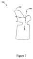
図7を参照すると、図7は、椎体702及びモーションパス704の一部を含む手術部位の例示的な二次元のマージされた画像700を示す。一例では、外科医は、器具Hを上述のように椎弓根標的部位に位置決めし、マージされた画像700を見て、モーションパス704の一部の軌道が手術計画と整合しているかどうかを決定し得る。この例では、外科医が、図示されているようにモーションパス704の一部を観察し、パイロットホールを形成するための対応する軌道を受け入れることに基づいて、外科医は、処理装置122を介して入力を提供し、決定されたモーションパスに沿ってロボット装置の1つ又は複数のコンポーネントを作動させる1つ又は複数の命令を決定するために画像700に関連するモーションパスを使用し得る。次いで、処理装置122は、ロボット装置140がモーションパス704の決定された一部に沿って必要な動作を実行できるようにするために、ロボット装置140に器具Hの向き及び位置情報を処理又は提供し得る。 Referring to FIG. 7, FIG. 7 shows an exemplary two-dimensional
代替的には、方法500は、モーションパスの一部を三次元画像上に表示することを含み得る。一例では、処理装置122は、セグメンテーションステップを実行するように構成されるコンピュータ実行可能命令を含み得る。本明細書で使用するとき、「セグメンテーション」は、椎骨を互いに区別して分離され、治療され、操作され、表示されることができるように三次元画像データ内で個々の椎骨を識別するプロセスを記載する。セグメンテーションステップは、イメージング処理及び画像認識ソフトウェアを使用して、脊椎レベルのセグメンテーション処理を自動化するセグメンテーションアルゴリズムを用い得る。一実施形態では、コンピュータ実行可能命令は、それらが互いにセグメント化されるまで、脊柱曲線を自動的に識別し、抽出し、各個々の椎骨を検出し、識別する。1つ又は複数の適応メッシュを適用して、脊椎のセグメント化三次元モデルを生成してもよい。各椎骨又は他の解剖学的特徴は、骨-軟組織境界面を視覚的に強める(enhance)ために別々に着色されることができる、又は縁(margin)だけが着色されることができる。 Alternatively,
図8を参照すると、図8は、他の椎骨からセグメント化された椎体802と、モーションパス804の一部とを含む、例示的な三次元画像800を示す。一例では、外科医は、本明細書に記載されるように、器具Hを椎弓根標的部位に位置決めし、三次元画像800を観察して、モーションパス804の一部の起動が手術計画と整合しているかどうかを判断し得る。この例では、外科医が、図示されているようにモーションパス804の一部を観察し、パイロットホールを形成するための対応する軌道を受け入れることに基づいて、外科医は、処理装置122を介して入力を提供し、決定されたモーションパスに沿ってロボット装置の1つ又は複数のコンポーネントを作動させる1つ又は複数の命令を決定するために、画像800に関連するモーションパスを使用し得る。次いで、処理装置122は、ロボット装置140がモーションパス804の決定された一部に沿って必要な動作を実行できるようにするために、ロボット装置140に器具Hの向き及び位置情報を処理又は提供し得る。 Referring to FIG. 8, FIG. 8 shows an example three-
再び図5を参照すると、ブロック514によって示されるように、方法500はまた、決定されたモーションパスに沿って1つ又は複数のコンポーネントを作動させるための1つ又は複数の命令を決定することを含む。一例では、ロボットツールを空間内に位置決めするために、ロボットのエンドエフェクタの位置及び向きを経時的に特定するロボットについて、ジョイント角度、速度、及び/又は加速度を含む一連のロボットジョイントパラメータが決定され得る。一例では、ロボットのジョイントパラメータと特定のタイムスタンプにおけるロボットツールの位置との間の直接的なマッピングが決定され得る。一例では、直接マッピングではなく、ロボットツールの位置を近似するためにロボットジョイントパラメータが決定され得る。一実施形態では、ロボットがロボットツールを動かしている間に、けいれん的(jerking)又は切れ切れの(disconnected)動きを回避するために、ロボット及び/又はロボットツールの動き曲線を滑らかにするためにロボットの動きは修正され得る。一例では、ロボットエンドエフェクタのモーションパス内の位置は、器具Hとロボットエンドエフェクタとの間のサイズの差を考慮するためにスケーリングされ(scaled)得る。 Referring again to FIG. 5, as indicated by
一例では、決定されたモーションパスに沿って1つ又は複数のコンポーネントを作動させるための1つ又は複数の命令は、ロボットに1つ又は複数の命令が提供される前に精緻化され(refined)得る。例えば、ロボットのモーションパスは、器具Hの決定されたモーションパスに対して、サイズを拡大又は縮小され得る。 In one example, the one or more instructions for actuating the one or more components along the determined motion path are refined before the one or more instructions are provided to the robot. obtain. For example, the motion path of the robot may be scaled up or down in size relative to the determined motion path of instrument H.
ブロック516によって示されるように、方法500はまた、1つ又は複数の命令をロボット装置に提供することを含む。一例では、1つ又は複数の命令は、処理装置122とロボット装置140との間の無線又は有線通信インタフェースを介して提供され得る。 As indicated by
図6を参照すると、手術処置中の例示的方法600は、ブロック602~616によって示されるように、1つ又は複数の操作、機能、又は動作を含み得る。一実施形態では、方法600は、全体的に又は部分的に、図1のシステム100によって実装される。 Referring to FIG. 6, an
ブロック602によって示されるように、方法600は、患者の手術部位の高解像度ベースライン画像を取得し、ベースライン画像セットを生成するために高解像度ベースライン画像をデジタル的に操作することを含む。ブロック602は、方法500のブロック502と機能的に類似し得る。 As indicated by
ブロック604によって示されるように、方法600はまた、より低い解像度で手術部位の新しい画像を取得し、新しい画像をベースライン画像セットの1つ又は複数の画像と比較することを含む。ブロック604は、方法500のブロック504と機能的に類似し得る。 As indicated by
ブロック606に示されるように、方法600はまた、新しい画像との許容可能な相関度を有するベースライン画像セットの代表画像を選択し、選択された代表画像を新しい画像とマージして、マージされた画像を生成することを含む。ブロック606は、方法500のブロック506と機能的に類似し得る。 As shown at
ブロック608によって示されるように、方法600はまた、患者の手術部位における器具のユーザ定義配置に基づいて器具の姿勢を取り込むことを含む。ブロック608は、方法500のブロック508と機能的に類似し得る。 As indicated by
ブロック610によって示されるように、方法600はまた、器具の取り込まれた姿勢に対応するモーションパスを決定することを含み、モーションパスは、ロボット装置の1つ又は複数のコンポーネントの作動に関連付けられる。ブロック610は、方法500のブロック510と機能的に類似し得る。 As indicated by
ブロック610はまた、或いは代わりに、ポータブル器具の1つ又は複数の赤外線反射器の位置を、患者に結合された1つ又は複数の赤外線反射器の位置と比較することを含み得る。ブロック610は、比較に基づいて、ポータブル器具の1つ又は複数の赤外線反射器と、患者に結合された1つ又は複数の赤外線反射器との間の距離が安全閾値内であることを決定することをさらに含み得る。この決定に基づいて、ブロック610は、ロボット装置の1つ又は複数のコンポーネントの作動に対する1つ又は複数の調整を決定することをさらに含み得る。
ブロック612によって示されるように、方法600はまた、マージされた画像上にモーションパスの一部を表示することを含む。ブロック612は、方法500のブロック512と機能的に類似し得る。代替的には、モーションパスの一部を椎骨の三次元画像上に表示することができる。 As indicated by
ブロック614によって示されるように、方法600はまた、決定されたモーションパスに沿って1つ又は複数のコンポーネントを作動させるための1つ又は複数の命令を決定することを含む。ブロック614は、方法500のブロック514と機能的に類似し得る。 As indicated by
ブロック616によって示されるように、方法600はまた、1つ又は複数の命令をロボット装置に提供することを含む。ブロック616は、方法500のブロック516と機能的に類似し得る。 As indicated by
図9を参照すると、手術処置中の例示的方法900は、ブロック902~912によって示されるように、1つ又は複数の操作、機能、又は動作を含み得る。一実施形態では、方法900は、全体的に又は部分的に、図1のシステム100によって実装される。 Referring to FIG. 9, an
ブロック902によって示されるように、方法900は、患者の手術部位の画像を取得することを含む。一例では、手術部位の画像は二次元画像であり得る。別の例では、患者の解剖学的構造の三次元画像データセットが、手術処置の前にシステムにロードされる。この画像データセットは、術前CTスキャン、術前MRI、又は術中イメージャーから取得された術中三次元画像データセットであり得る。1つのシナリオでは、三次元画像データセットは、画像処理装置122にアップロードされ、一連のDRRに変換されて、取得可能なすべての可能な二次元Cアーム画像を近似し、したがって、術中二次元画像を比較しマッチングするためのベースラインとして機能する。 As indicated by
ブロック904によって示されるように、方法900はまた、手術部位へのユーザ定義パスに基づいて器具のモーションデータを取り込むことを含む。ブロック904は、方法500のブロック508と機能的に類似し得る。 As indicated by
ブロック906によって示されるように、方法900はまた、取り込まれたモーションデータに対応するモーションパスを決定することを含み、モーションパスは、ロボット装置の1つ又は複数のコンポーネントの作動に関連付けられる。ブロック906は、方法500のブロック510と機能的に類似し得る。 As indicated by
ブロック908によって示されるように、方法900はまた、マージされた画像上にモーションパスの一部を表示することを含む。ブロック908は、方法500のブロック512と機能的に類似し得る。 As indicated by
ブロック910によって示されるように、方法900はまた、決定されたモーションパスに沿って1つ又は複数のコンポーネントを作動させるための1つ又は複数の命令を決定することを含む。ブロック910は、方法500のブロック514と機能的に類似し得る。 As indicated by
ブロック912によって示されるように、方法900はまた、1つ又は複数の命令をロボット装置に提供することを含む。ブロック912は、方法500のブロック516と機能的に類似し得る。 As indicated by
図10を参照すると、手術処置中の例示的方法1000は、ブロック1002~1012によって示されるように、1つ又は複数の操作、機能、又は動作を含み得る。一実施形態では、方法900は、全体的に又は部分的に、図1のシステム100によって実装される。 Referring to FIG. 10, an
ブロック1002によって示されるように、方法1000は、患者の手術部位の画像を取得することを含む。ブロック1002は、方法900のブロック902と機能的に類似し得る。 As indicated by
ブロック1004によって示されるように、方法1000はまた、患者の手術部位における器具のユーザ定義配置に基づいて器具の姿勢を取り込むことを含む。ブロック1004は、方法500のブロック508と的に類似し得る。 As indicated by
ブロック1006によって示されるように、方法1000はまた、器具の取り込まれた姿勢に対応するモーションパスを決定することを含み、モーションパスは、ロボット装置の1つ又は複数のコンポーネントの作動に関連付けられる。ブロック1006は、方法500のブロック510と機能的に類似し得る。 As indicated by
ブロック1008によって示されるように、方法1000はまた、マージされた画像上にモーションパスの一部を表示することを含む。ブロック1008は、方法500のブロック512と機能的に類似し得る。 As indicated by
ブロック1010によって示されるように、方法1000はまた、決定されたモーションパスに沿って1つ又は複数のコンポーネントを作動させるための1つ又は複数の命令を決定することを含む。ブロック1010は、方法500のブロック514と機能的に類似し得る。 As indicated by
ブロック1012によって示されるように、方法1000はまた、1つ又は複数の命令をロボット装置に提供することを含む。ブロック1012は、方法500のブロック516と機能的に類似し得る。 As indicated by
本明細書に記載される構成は、単に例示の目的のためのものであることが理解されるべきである。したがって、当業者であれば、他の構成及び他の要素(例えば、マシン、インタフェース、機能、命令、及び機能のグループ化など)を代わりに使用することができ、所望の結果に従って一部の要素が完全に省略され得ることを理解するであろう。さらに、記載される要素の多くは、任意の適切な組み合わせ及び位置において、別個の若しくは分散コンポーネントとして、又は他のコンポーネントと共に実装され得る機能的エンティティであり、又は独立した構造として記載される他の構造要素が組み合わされ得る。 It should be understood that the configurations described herein are for illustrative purposes only. Accordingly, those skilled in the art will recognize that other configurations and other elements (e.g., machines, interfaces, functions, instructions, and groupings of functions, etc.) may be used instead, and some elements may be modified according to the desired result. It will be appreciated that the can be omitted entirely. Additionally, many of the elements described are functional entities that can be implemented as separate or distributed components or in conjunction with other components, in any suitable combination and position, or other components described as independent structures. Structural elements may be combined.
Claims (9)
Translated fromJapanese前記システムが、患者の手術部位の画像を取得することと;
前記追跡装置が、前記手術部位へのユーザ定義パスに基づいて、器具のモーションデータを取り込むことと;
前記処理装置が、取り込まれた前記モーションデータに基づいてモーションパスを決定することであって、前記モーションパスは、前記ロボット装置の1つ又は複数のコンポーネントの作動に対応する、決定することと;
前記システムが、前記モーションパスの一部を前記画像上に表示することと;
前記処理装置が、決定された前記モーションパスに沿って前記1つ又は複数のコンポーネントを作動させるための1つ又は複数の命令を決定することと;
前記処理装置が、前記モーションパスと交差すべきではない前記手術部位内の1つ又は複数の所定の境界と前記モーションパスが交差することを決定することと;
前記処理装置が、前記決定されたモーションパスの変化する視覚効果の表示を提供することと;
前記処理装置が、前記1つ又は複数の命令を前記ロボット装置に提供することと;を含み、
前記ユーザ定義パスは、外科医によって保持されるポータブル器具の動きに基づき、
前記ポータブル器具は、1つ又は複数の赤外線反射器を有し、
前記取り込まれたモーションデータに対応するモーションパスを決定することは:
前記処理装置が、前記ポータブル器具の前記1つ又は複数の赤外線反射器の位置を、前記患者に結合された1つ又は複数の赤外線反射器の位置と比較することと;
前記処理装置が、前記比較に基づいて、前記ポータブル器具の前記1つ又は複数の赤外線反射器と前記患者に結合された前記1つ又は複数の赤外線反射器との間の距離が安全閾値内にあることを決定することと;
前記処理装置が、前記決定に基づいて、前記ロボット装置の前記1つ又は複数のコンポーネントの作動に対する1つ又は複数の調整を決定することと;をさらに含む、
作動方法。A method of operating a system having a tracking device, a robotic device, and a processing device, the method comprising:
the system acquiring an image of a surgical site of a patient;
the tracking device captures instrument motion data based on a user-defined path to the surgical site;
the processing device determining a motion path based on the captured motion data, the motion path corresponding to actuation of one or more components of the robotic device;
the system displaying a portion of the motion path on the image;
the processing unit determining one or more instructions for operating the one or more components along the determined motion path;
the processing unit determining that the motion path intersects one or more predetermined boundaries within the surgical site that the motion path should not intersect;
the processing device provides a display of a changing visual effect of the determined motion path;
the processing device providing the one or more instructions to the robotic device;
the user-defined path is based on movement of a portable instrument held by the surgeon;
the portable appliance has one or more infrared reflectors;
Determining a motion path corresponding to the captured motion data includes:
the processing device comparing the position of the one or more infrared reflectors of the portable device to the position of one or more infrared reflectors coupled to the patient;
The processing device determines, based on the comparison, that a distance between the one or more infrared reflectors of the portable device and the one or more infrared reflectors coupled to the patient is within a safety threshold. to decide something;
the processing device determining one or more adjustments to the operation of the one or more components of the robotic device based on the determination;
How it works.
請求項1に記載の作動方法。The image of the surgical site is a three-dimensional image.
An actuation method according to claim 1.
前記処理装置が、前記決定されたモーションパスの前記一部が手術計画と整合することを確認する入力を受信することをさらに含む、
請求項2に記載の作動方法。Providing the one or more instructions to the robotic device includes:
further comprising: the processing unit receiving input confirming that the portion of the determined motion path is consistent with a surgical plan;
The actuation method according to claim2 .
前記システムが、患者の手術部位の三次元画像を取得することと;
前記追跡装置が、患者の手術部位における器具のユーザ定義配置に基づいて前記器具の姿勢を取り込むことと;
前記処理装置が、前記器具の取り込まれた前記姿勢に対応するモーションパスを決定することであって、前記モーションパスは、前記ロボット装置の1つ又は複数のコンポーネントの作動に関連付けられる、決定することと;
前記処理装置が、前記三次元画像上に前記モーションパスの一部を表示することと;
前記処理装置が、前記決定されたモーションパスに沿って前記1つ又は複数のコンポーネントを作動させるための1つ又は複数の命令を決定することと;
前記処理装置が、前記モーションパスと交差すべきではない前記手術部位内の1つ又は複数の所定の境界と前記モーションパスが交差することを決定することと;
前記処理装置が、前記決定されたモーションパスの変化する視覚効果の表示を提供することと;
前記処理装置が、前記1つ又は複数の命令を前記ロボット装置に提供することと;を含み、
前記ユーザ定義配置は、外科医によって保持されるポータブル器具の動きに基づき、
前記ポータブル器具は、1つ又は複数の赤外線反射器を有し、
前記取り込まれたモーションデータに対応するモーションパスを決定することは:
前記処理装置が、前記ポータブル器具の前記1つ又は複数の赤外線反射器の位置を、前記患者に結合された1つ又は複数の赤外線反射器の位置と比較することと;
前記処理装置が、前記比較に基づいて、前記ポータブル器具の前記1つ又は複数の赤外線反射器と前記患者に結合された前記1つ又は複数の赤外線反射器との間の距離が安全閾値内にあることを決定することと;
前記処理装置が、前記決定に基づいて、前記ロボット装置の前記1つ又は複数のコンポーネントの作動に対する1つ又は複数の調整を決定することと;をさらに含む、
作動方法。A method of operating a system having a tracking device, a robotic device, and a processing device, the method comprising:
the system acquiring a three-dimensional image of the patient's surgical site;
the tracking device captures a posture of the instrument based on a user-defined placement of the instrument at a patient's surgical site;
the processing device determining a motion path corresponding to the captured pose of the instrument, the motion path being associated with actuation of one or more components of the robotic device; and;
the processing device displays a portion of the motion path on the three-dimensional image;
the processing unit determining one or more instructions for operating the one or more components along the determined motion path;
the processing unit determining that the motion path intersects one or more predetermined boundaries within the surgical site that the motion path should not intersect;
the processing device provides a display of a changing visual effect of the determined motion path;
the processing device providing the one or more instructions to the robotic device;
the user-defined placement is based on movement of a portable instrument held by the surgeon;
the portable appliance has one or more infrared reflectors;
Determining a motion path corresponding to the captured motion data includes:
the processing device comparing the position of the one or more infrared reflectors of the portable device to the position of one or more infrared reflectors coupled to the patient;
The processing device determines, based on the comparison, that a distance between the one or more infrared reflectors of the portable device and the one or more infrared reflectors coupled to the patient is within a safety threshold. to decide something;
the processing device determining one or more adjustments to the operation of the one or more components of the robotic device based on the determination;
How it works.
請求項4に記載の作動方法。The image of the surgical site is a three-dimensional image.
The actuation method according to claim4 .
前記処理装置が、前記決定されたモーションパスの前記一部が手術計画と整合することを確認する入力を受信することをさらに含む、
請求項5に記載の作動方法。Providing the one or more instructions to the robotic device includes:
further comprising: the processing unit receiving input confirming that the portion of the determined motion path is consistent with a surgical plan;
The actuation method according to claim5 .
追跡装置と;
ロボット装置と;
処理装置であって:
プロセッサ、及び
命令を記憶した非一時的コンピュータ可読媒体であって、前記命令は、前記プロセッサによって実行されるとき、前記システムに:
患者の手術部位の画像を受信させ;
患者の手術部位における器具のユーザ定義配置に基づいて前記追跡装置により前記器具の姿勢を取り込ませ;
前記プロセッサによって、前記器具の取り込まれた前記姿勢に対応するモーションパスを決定させ、前記モーションパスは、前記ロボット装置の1つ又は複数のコンポーネントの作動に関連付けられ;
前記モーションパスの一部を前記画像上に表示する命令を提供させ;
前記プロセッサによって、決定された前記モーションパスに沿って前記1つ又は複数のコンポーネントを作動させるための1つ又は複数の命令を決定させ;
前記モーションパスと交差すべきではない前記手術部位内の1つ又は複数の所定の境界と前記モーションパスが交差することを決定させ;
ディスプレイにより前記決定されたモーションパスの変化する視覚効果の表示を提供させ;
前記1つ又は複数の命令を前記ロボット装置に提供させる;
非一時的コンピュータ可読媒体を有する、
処理装置と;を有し、
前記ユーザ定義配置は、外科医によって保持されるポータブル器具の動きに基づき、
前記ポータブル器具は、1つ又は複数の赤外線反射器を有し、
前記プロセッサによって実行されるとき、前記システムに、前記取り込まれたモーションデータに対応するモーションパスを決定させる命令を記憶した前記非一時的コンピュータ可読媒体は:
前記ポータブル器具の前記1つ又は複数の赤外線反射器の位置を、前記患者に結合された1つ又は複数の赤外線反射器の位置と比較し;
前記比較に基づいて、前記ポータブル器具の前記1つ又は複数の赤外線反射器と前記患者に結合された前記1つ又は複数の赤外線反射器との間の距離が安全閾値内にあることを決定し;
前記決定に基づいて、前記ロボット装置の前記1つ又は複数のコンポーネントの作動に対する1つ又は複数の調整を決定する;
命令をさらに含む、
システム。The system is:
tracking device;
robotic equipment;
A processing device:
a processor; and a non-transitory computer-readable medium having instructions stored thereon, the instructions, when executed by the processor, causing the system to:
receiving images of the patient's surgical site;
causing the tracking device to capture the posture of the instrument based on a user-defined placement of the instrument at the patient's surgical site;
causing the processor to determine a motion path corresponding to the captured pose of the instrument, the motion path being associated with actuation of one or more components of the robotic device;
providing instructions for displaying a portion of the motion path on the image;
causing the processor to determine one or more instructions for operating the one or more components along the determined motion path;
determining that the motion path intersects one or more predetermined boundaries within the surgical site that should not be intersected by the motion path;
causing a display to provide a display of a changing visual effect of the determined motion path;
causing the robotic device to provide the one or more instructions;
having a non-transitory computer-readable medium;
a processing device;
the user-defined placement is based on movement of a portable instrument held by the surgeon;
the portable appliance has one or more infrared reflectors;
The non-transitory computer-readable medium stores instructions that, when executed by the processor, cause the system to determine a motion path corresponding to the captured motion data:
comparing the position of the one or more infrared reflectors of the portable device to the position of one or more infrared reflectors coupled to the patient;
based on the comparison, determining that a distance between the one or more infrared reflectors of the portable device and the one or more infrared reflectors coupled to the patient is within a safety threshold; ;
determining one or more adjustments to the operation of the one or more components of the robotic device based on the determination;
further including instructions,
system.
請求項7に記載のシステム。The image of the surgical site is a three-dimensional image.
The system according to claim7 .
前記決定されたモーションパスの前記一部が手術計画と整合することを確認する入力を受信する命令をさらに含む、
請求項8に記載のシステム。The non-transitory computer-readable medium stores instructions that, when executed by the processor, cause the system to provide the one or more instructions to the robotic device:
further comprising instructions for receiving input confirming that the portion of the determined motion path is consistent with a surgical plan;
The system according to claim8 .
Applications Claiming Priority (5)
| Application Number | Priority Date | Filing Date | Title |
|---|---|---|---|
| US201962794545P | 2019-01-18 | 2019-01-18 | |
| US62/794,545 | 2019-01-18 | ||
| US16/544,915US11229493B2 (en) | 2019-01-18 | 2019-08-20 | Motion programming of a robotic device |
| US16/544,915 | 2019-08-20 | ||
| PCT/US2020/014131WO2020150629A1 (en) | 2019-01-18 | 2020-01-17 | Motion programming of a robotic device |
Publications (2)
| Publication Number | Publication Date |
|---|---|
| JP2022518020A JP2022518020A (en) | 2022-03-11 |
| JP7351915B2true JP7351915B2 (en) | 2023-09-27 |
Family
ID=71610488
Family Applications (1)
| Application Number | Title | Priority Date | Filing Date |
|---|---|---|---|
| JP2021541237AActiveJP7351915B2 (en) | 2019-01-18 | 2020-01-17 | Motion programming of robot equipment |
Country Status (6)
| Country | Link |
|---|---|
| US (2) | US11229493B2 (en) |
| EP (1) | EP3911263A1 (en) |
| JP (1) | JP7351915B2 (en) |
| CN (1) | CN113316430B (en) |
| AU (1) | AU2020208635A1 (en) |
| WO (1) | WO2020150629A1 (en) |
Families Citing this family (8)
| Publication number | Priority date | Publication date | Assignee | Title |
|---|---|---|---|---|
| US9968408B1 (en) | 2013-03-15 | 2018-05-15 | Nuvasive, Inc. | Spinal balance assessment |
| US10695099B2 (en) | 2015-02-13 | 2020-06-30 | Nuvasive, Inc. | Systems and methods for planning, performing, and assessing spinal correction during surgery |
| WO2017151949A1 (en)* | 2016-03-02 | 2017-09-08 | Nuvasive, Inc. | Systems and methods for spinal correction surgical planning |
| US20210361357A1 (en)* | 2017-07-21 | 2021-11-25 | Globus Medical, Inc. | Robot surgical platform |
| US11229493B2 (en)* | 2019-01-18 | 2022-01-25 | Nuvasive, Inc. | Motion programming of a robotic device |
| CN111035454B (en)* | 2019-12-26 | 2021-09-10 | 苏州微创畅行机器人有限公司 | Readable storage medium and surgical robot |
| US11432892B1 (en)* | 2021-03-02 | 2022-09-06 | Mazor Robotics Ltd. | Systems and methods for cutting an anatomical element |
| WO2023276238A1 (en)* | 2021-07-02 | 2023-01-05 | ソニーグループ株式会社 | Robot control device and robot control method |
Citations (5)
| Publication number | Priority date | Publication date | Assignee | Title |
|---|---|---|---|---|
| US20120029387A1 (en) | 2010-07-09 | 2012-02-02 | Edda Technology, Inc. | Methods and systems for real-time surgical procedure assistance using an electronic organ map |
| JP2012518453A (en) | 2009-02-25 | 2012-08-16 | フィリップス エレクトロニクス リミテッド | Method, system and apparatus for transjugular intrahepatic portal generalization shunting |
| JP2012533333A (en) | 2009-07-15 | 2012-12-27 | コーニンクレッカ フィリップス エレクトロニクス エヌ ヴィ | Visualization of surgical trajectory |
| JP2014147455A (en) | 2013-01-31 | 2014-08-21 | Toshiba Corp | Medical image diagnostic apparatus and paracentesis support device |
| US20150366624A1 (en) | 2014-06-19 | 2015-12-24 | KB Medical SA | Systems and methods for performing minimally invasive surgery |
Family Cites Families (18)
| Publication number | Priority date | Publication date | Assignee | Title |
|---|---|---|---|---|
| US8526700B2 (en)* | 2010-10-06 | 2013-09-03 | Robert E. Isaacs | Imaging system and method for surgical and interventional medical procedures |
| US9308050B2 (en) | 2011-04-01 | 2016-04-12 | Ecole Polytechnique Federale De Lausanne (Epfl) | Robotic system and method for spinal and other surgeries |
| US10874466B2 (en) | 2012-06-21 | 2020-12-29 | Globus Medical, Inc. | System and method for surgical tool insertion using multiaxis force and moment feedback |
| US10624710B2 (en) | 2012-06-21 | 2020-04-21 | Globus Medical, Inc. | System and method for measuring depth of instrumentation |
| US9056396B1 (en)* | 2013-03-05 | 2015-06-16 | Autofuss | Programming of a robotic arm using a motion capture system |
| WO2015135055A1 (en)* | 2014-03-14 | 2015-09-17 | Synaptive Medical (Barbados) Inc. | System and method for projected tool trajectories for surgical navigation systems |
| US20160074123A1 (en) | 2013-05-31 | 2016-03-17 | Randall Bly | Surgery Pathway Guidance And Boundary System |
| US9283048B2 (en) | 2013-10-04 | 2016-03-15 | KB Medical SA | Apparatus and systems for precise guidance of surgical tools |
| US10058394B2 (en) | 2015-07-31 | 2018-08-28 | Globus Medical, Inc. | Robot arm and methods of use |
| US10646298B2 (en) | 2015-07-31 | 2020-05-12 | Globus Medical, Inc. | Robot arm and methods of use |
| US10034716B2 (en) | 2015-09-14 | 2018-07-31 | Globus Medical, Inc. | Surgical robotic systems and methods thereof |
| CN105852970B (en)* | 2016-04-29 | 2019-06-14 | 北京柏惠维康科技有限公司 | Neurosurgical Robot navigation positioning system and method |
| CN107708594B (en) | 2016-06-03 | 2021-03-05 | 柯惠Lp公司 | Control arm assembly for robotic surgical system |
| US11039893B2 (en) | 2016-10-21 | 2021-06-22 | Globus Medical, Inc. | Robotic surgical systems |
| US11135015B2 (en) | 2017-07-21 | 2021-10-05 | Globus Medical, Inc. | Robot surgical platform |
| CN112672710A (en)* | 2018-09-05 | 2021-04-16 | 纽文思公司 | Systems and methods for spinal surgery |
| US11229493B2 (en)* | 2019-01-18 | 2022-01-25 | Nuvasive, Inc. | Motion programming of a robotic device |
| US11065065B2 (en) | 2019-02-22 | 2021-07-20 | Warsaw Orthopedic, Inc. | Spinal implant system and methods of use |
- 2019
- 2019-08-20USUS16/544,915patent/US11229493B2/enactiveActive
- 2020
- 2020-01-17WOPCT/US2020/014131patent/WO2020150629A1/ennot_activeCeased
- 2020-01-17AUAU2020208635Apatent/AU2020208635A1/ennot_activeAbandoned
- 2020-01-17JPJP2021541237Apatent/JP7351915B2/enactiveActive
- 2020-01-17EPEP20707889.0Apatent/EP3911263A1/enactivePending
- 2020-01-17CNCN202080009616.9Apatent/CN113316430B/enactiveActive
- 2021
- 2021-12-14USUS17/550,318patent/US12059221B2/enactiveActive
Patent Citations (5)
| Publication number | Priority date | Publication date | Assignee | Title |
|---|---|---|---|---|
| JP2012518453A (en) | 2009-02-25 | 2012-08-16 | フィリップス エレクトロニクス リミテッド | Method, system and apparatus for transjugular intrahepatic portal generalization shunting |
| JP2012533333A (en) | 2009-07-15 | 2012-12-27 | コーニンクレッカ フィリップス エレクトロニクス エヌ ヴィ | Visualization of surgical trajectory |
| US20120029387A1 (en) | 2010-07-09 | 2012-02-02 | Edda Technology, Inc. | Methods and systems for real-time surgical procedure assistance using an electronic organ map |
| JP2014147455A (en) | 2013-01-31 | 2014-08-21 | Toshiba Corp | Medical image diagnostic apparatus and paracentesis support device |
| US20150366624A1 (en) | 2014-06-19 | 2015-12-24 | KB Medical SA | Systems and methods for performing minimally invasive surgery |
Also Published As
| Publication number | Publication date |
|---|---|
| CN113316430B (en) | 2025-01-07 |
| US12059221B2 (en) | 2024-08-13 |
| US20220096180A1 (en) | 2022-03-31 |
| CN113316430A (en) | 2021-08-27 |
| AU2020208635A1 (en) | 2021-08-05 |
| EP3911263A1 (en) | 2021-11-24 |
| WO2020150629A1 (en) | 2020-07-23 |
| JP2022518020A (en) | 2022-03-11 |
| US20200229878A1 (en) | 2020-07-23 |
| US11229493B2 (en) | 2022-01-25 |
Similar Documents
| Publication | Publication Date | Title |
|---|---|---|
| JP7399982B2 (en) | 3D visualization during surgery | |
| JP7351915B2 (en) | Motion programming of robot equipment | |
| JP7679602B2 (en) | Systems and methods for spinal surgery - Patents.com | |
| US12272080B2 (en) | Systems and methods for anatomical segmentation | |
| CN115426967B (en) | Spinal surgery planning device and method based on two-dimensional medical images | |
| JP6083103B2 (en) | Image complementation system for image occlusion area, image processing apparatus and program thereof | |
| US20220330986A1 (en) | Robot assisted rod bending | |
| EP3944254A1 (en) | System for displaying an augmented reality and method for generating an augmented reality | |
| US20230270507A1 (en) | Surgical Imaging And Display System, And Related Methods |
Legal Events
| Date | Code | Title | Description |
|---|---|---|---|
| A621 | Written request for application examination | Free format text:JAPANESE INTERMEDIATE CODE: A621 Effective date:20210921 | |
| A131 | Notification of reasons for refusal | Free format text:JAPANESE INTERMEDIATE CODE: A131 Effective date:20220823 | |
| A977 | Report on retrieval | Free format text:JAPANESE INTERMEDIATE CODE: A971007 Effective date:20220826 | |
| A521 | Request for written amendment filed | Free format text:JAPANESE INTERMEDIATE CODE: A523 Effective date:20221122 | |
| A131 | Notification of reasons for refusal | Free format text:JAPANESE INTERMEDIATE CODE: A131 Effective date:20230322 | |
| A521 | Request for written amendment filed | Free format text:JAPANESE INTERMEDIATE CODE: A523 Effective date:20230619 | |
| TRDD | Decision of grant or rejection written | ||
| A01 | Written decision to grant a patent or to grant a registration (utility model) | Free format text:JAPANESE INTERMEDIATE CODE: A01 Effective date:20230905 | |
| A61 | First payment of annual fees (during grant procedure) | Free format text:JAPANESE INTERMEDIATE CODE: A61 Effective date:20230914 | |
| R150 | Certificate of patent or registration of utility model | Ref document number:7351915 Country of ref document:JP Free format text:JAPANESE INTERMEDIATE CODE: R150 |